rear band adjustment - ck performance - street band adjustment.pdf · rear band adjustment...
TRANSCRIPT

Rear Band Adjustment
Understanding Rear Band Adjustment
The objective of the rear band adjustment is to maintain adequate clearance between the
rear band and reaction carrier drum surface when the servo is released, and to ensure full
apply of the rear band when the servo is applied. There are specific demands that must be
met during both the applied and released phases of rear servo operation in order to obtain
maximum operating efficiency and component performance. Insufficient clearance during
release will result in a partial apply of the rear band, causing the rear band to drag on the
reaction carrier, reducing operating efficiency. Over time this will result in erosion of the
band lining and reaction carrier drum surface. Excessive clearance during apply will result
in a partial apply of the rear band, causing slipping between the band and reaction carrier.
This can result in slipping or no movement in Reverse Range and no engine braking in
Manual Low Range. If the vehicle is equipt with a transmission brake, poor performance of
the device will result. Figure 15-30 shows the “as installed” position of the rear servo piston
relative to the transmission case with the aid of a sectioned rear servo cover. When the servo
piston is released, the face of its minor diameter rests against the inside of the rear servo
cover and the face of its major diameter is approximately .025” below the servo cover
mounting face of the transmission case at the location called out in Figure 15-33. When the
servo is applied, pressurized oil pushes or ‘strokes” the servo assembly, applying the rear
band. The amount of servo piston travel, from the released position to the applied position is
measured and adjusted to obtain proper rear band adjustment. The specification for this
travel is .125” to .150”. Travel is adjusted thru the use of selective band apply pins or
modification of the original pin.
FIGURE 15-30
Rear Band Adjustment

Install the rear servo piston into the rear servo bore in the transmission case. See Figure
15-31. Do not fit the rear servo piston seal, accumulator piston, or accumulator spring at this
time. Reach into the transmission case and firmly grasp the sun gear shaft and main shaft.
Simultaneously rotate them in a clockwise direction as viewed from the front of the
transmission. See Figure 15-32. The rotation of these two items should result in a direct drive
of the complete geartrain assembly. Pay attention to the amount of force required to rotate
the assembly.
FIGURE 15-31 FIGURE 15-32
Continue rotating the assembly while applying downward force on the servo piston until
the mass will no longer rotate. When the mass will no longer rotate, the distance from the
servo cover mounting flange to the servo piston major diameter should be between .150” to
.175”. Because the mounting flange is not perpendicular to the pin bore, it is imperative the
distance be checked only within the center of the arc between the two mounting bolt holes.
See Figure 15-33. Measure distance with a caliper.
FIGURE 15-33
If the servo piston does not travel down in the bore far enough you will grind off the end
of the servo pin until the specifications are met. Servo piston pins are selective to allow

adjustment of the rear band clearance. If the servo piston travels further down in the bore
than specified, you will need to install a longer servo pin so that the specifications can be met.
Identify the appropriate selective pin necessary from Figure 15-39. If access to selective pins
is not available it is acceptable to weld up the pin tip to extend pin length.
A simple tool for checking rear band clearance can be fashioned from a spare rear servo
cover and a 5/16-18 x 1.5” bolt. The center of the cover is drilled and tapped to accept the
bolt. The cover is cut or “sectioned” to gain access to the measurement area. See Figures 15-
34 and 15-35. Fit the tool to transmission case, carefully snugging the bolts with a speed
handle. Tighten the bolt to 55 inch pounds to preload the servo assembly. Take measurement
and make adjustments as necessary.
FIGURE 15-34
FIGURE 15-35
Checking and Adjusting Rear Band with Early OEM Tooling
Install the small diameter end of the gage pin (J-21370-5) into the rear servo bore and
attach the rear band apply pin selection gage (J-21370-6) to the transmission case with the
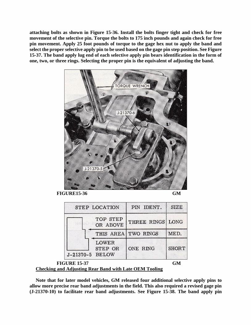
attaching bolts as shown in Figure 15-36. Install the bolts finger tight and check for free
movement of the selective pin. Torque the bolts to 175 inch pounds and again check for free
pin movement. Apply 25 foot pounds of torque to the gage hex nut to apply the band and
select the proper selective apply pin to be used based on the gage pin step position. See Figure
15-37. The band apply lug end of each selective apply pin bears identification in the form of
one, two, or three rings. Selecting the proper pin is the equivalent of adjusting the band.
FIGURE15-36 GM
FIGURE 15-37 GM
Checking and Adjusting Rear Band with Late OEM Tooling
Note that for later model vehicles, GM released four additional selective apply pins to
allow more precise rear band adjustments in the field. This also required a revised gage pin
(J-21370-10) to facilitate rear band adjustments. See Figure 15-38. The band apply pin

selection gage and measurement methods are the same as previously mentioned. Select the
proper selective apply pin to be used based on the gage pin step position. The band apply lug
end of each selective apply pin bears identification relative to the pins overall length. Select
the correct pin from the chart that coincides with the gage pin step position. See Figures 15-
38 and 15-39. Selecting the proper pin is the equivalent of adjusting the band.
FIGURE 15-38 GM FIGURE 15-39 GM