zenoss core configuration guide - zenoss help center · zenoss core configuration guide 8 5...
TRANSCRIPT
Zenoss Core Configuration GuideRelease 6.1.2
Zenoss, Inc.
www.zenoss.com
2
Zenoss Core Configuration Guide
Copyright © 2018 Zenoss, Inc. All rights reserved.
Zenoss, Own IT, and the Zenoss logo are trademarks or registered trademarks of Zenoss, Inc., in the United States and other countries. All othertrademarks, logos, and service marks are the property of Zenoss or other third parties. Use of these marks is prohibited without the express writtenconsent of Zenoss, Inc., or the third-party owner.
Amazon Web Services, AWS, and EC2 are trademarks of Amazon.com, Inc. or its affiliates in the United States and/or other countries.
Flash is a registered trademark of Adobe Systems Incorporated.
Oracle, the Oracle logo, Java, and MySQL are registered trademarks of the Oracle Corporation and/or its affiliates.
Linux is a registered trademark of Linus Torvalds.
RabbitMQ is a trademark of Pivotal Software, Inc.
SNMP Informant is a trademark of Garth K. Williams (Informant Systems, Inc.).
Sybase is a registered trademark of Sybase, Inc.
Tomcat is a trademark of the Apache Software Foundation.
VMware is a registered trademark or trademark of VMware, Inc. in the United States and/or other jurisdictions.
Windows is a registered trademark of Microsoft Corporation in the United States and other countries.
All other companies and products mentioned are trademarks and property of their respective owners.
Part Number: 1641.18.082.22
Zenoss, Inc.11305 Four Points DriveBldg 1 - Suite 300Austin, Texas 78726
3
Contents
About this guide.......................................................................................................................4
Chapter 1: Enabling access to browser interfaces..........................................5Creating and changing public endpoints.....................................................................................................5Configuring name resolution for virtual hosts.......................................................................................... 12
Chapter 2: Configuring Zenoss Core.............................................................14Starting Zenoss Core................................................................................................................................. 14Default server passwords...........................................................................................................................15Deleting the RabbitMQ guest user account.............................................................................................. 18MariaDB database utilities........................................................................................................................ 18Optional: Assigning a virtual IP address to a resource pool.................................................................... 20Optional: Replacing the default digital certificate.................................................................................... 20Optional: Enabling monitoring on IPv6 networks.................................................................................... 21Optional: Customization management...................................................................................................... 22Optional: Configuring OpenTSDB compaction........................................................................................24
Chapter 3: Preparing for monitoring............................................................ 25Extending monitoring with ZenPacks....................................................................................................... 25Preparing network devices.........................................................................................................................26Preparing storage devices.......................................................................................................................... 27Preparing server devices............................................................................................................................29Preparing hypervisor devices.....................................................................................................................30Validating configuration using Inspector tool...........................................................................................31Optional: Enabling monitoring on IPv6 networks.................................................................................... 31
Chapter 4: Modeling devices...........................................................................33Configuring Windows devices to provide data through SNMP............................................................... 33Configuring Linux devices to provide data through SNMP..................................................................... 34Modeling devices using SSH/COMMAND.............................................................................................. 34Using device class to monitor devices using SSH....................................................................................35Using the /Server/Scan device class to monitor with port scan................................................................35Modeling devices using port scan.............................................................................................................35About modeler plugins.............................................................................................................................. 36Debugging the modeling process.............................................................................................................. 37Next steps...................................................................................................................................................37
Appendix A: External HBase configuration..................................................38Configuring OpenTSDB for an external HBase cluster........................................................................... 38Configuring the OpenTSDB service startup command............................................................................ 39Disabling the Zenoss Core HBase cluster.................................................................................................39
Zenoss Core Configuration Guide
4
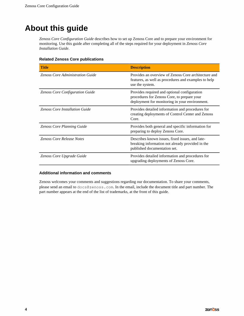
About this guideZenoss Core Configuration Guide describes how to set up Zenoss Core and to prepare your environment formonitoring. Use this guide after completing all of the steps required for your deployment in Zenoss CoreInstallation Guide.
Related Zenoss Core publications
Title Description
Zenoss Core Administration Guide Provides an overview of Zenoss Core architecture andfeatures, as well as procedures and examples to helpuse the system.
Zenoss Core Configuration Guide Provides required and optional configurationprocedures for Zenoss Core, to prepare yourdeployment for monitoring in your environment.
Zenoss Core Installation Guide Provides detailed information and procedures forcreating deployments of Control Center and ZenossCore.
Zenoss Core Planning Guide Provides both general and specific information forpreparing to deploy Zenoss Core.
Zenoss Core Release Notes Describes known issues, fixed issues, and late-breaking information not already provided in thepublished documentation set.
Zenoss Core Upgrade Guide Provides detailed information and procedures forupgrading deployments of Zenoss Core.
Additional information and comments
Zenoss welcomes your comments and suggestions regarding our documentation. To share your comments,please send an email to [email protected]. In the email, include the document title and part number. Thepart number appears at the end of the list of trademarks, at the front of this guide.
Enabling access to browser interfaces
5
Enabling access to browser interfaces 1Control Center and Zenoss Core have independent browser interfaces that are served by independent webservers. Both web servers are configured to use SSL/TLS communications.
The Control Center web server listens at the hostname of the Control Center master host and port 443. For aControl Center master host with the fully qualified domain name (FQDN) cc-master.example.com, thehostname URL is https://cc-master. You can substitute an IP address for the hostname portion of theURL.
The Zenoss Core web server can listen at port public endpoints and virtual host public endpoints.
■ A port public endpoint is a combination of the IP address or hostname of the Control Center master hostand a port number. The default configuration of Zenoss Core does not include any port public endpoints. Ifthe Control Center master host has more than one interface, you can configure port public endpoints withdifferent hostnames. Also, you can disable TLS communications for a port public endpoint.
To use a port public endpoint to gain access to the Zenoss Core browser interface, no additional networkname resolution entries are required. The default entries for the network interfaces of the Control Centermaster host are sufficient.
■ The default virtual host public endpoint is the text zenoss5 prefixed to the hostname of the Control Centermaster host and port 443. For the FQDN cc-master.example.com, the URL of the default virtualhost public endpoint is https://zenoss5.cc-master:443. You can change the name of the defaultvirtual host and configure additional virtual host public endpoints.
To use a virtual host public endpoint to gain access to the Zenoss Core browser interface, you must addname resolution entries for the virtual host to the DNS servers in your environment or to the hosts files ofindividual client systems.
The following sections provide additional information about public endpoints, and instructions for creatingpublic endpoints and configuring virtual hostname resolution.
Creating and changing public endpoints
This section provides instructions for creating and changing port public endpoints and virtual host publicendpoints.
Zenoss Core Configuration Guide
6
Creating public endpoints overview
The following table lists communication requirements and outlines the process for creating public endpoints.Step-by-step instructions follow this overview.
Port public endpoint Virtual host public endpoint
Port public endpoints can communicatewith or without SSL/TLS.
1 Create the endpoint.2 Configure the Zope service.
Virtual host public endpoints must use SSL/TLScommunications.
1 Create the endpoint.2 Configure the Zope service.3 Configure virtual hostname resolution.
Changing public endpoints
To change an existing public endpoint, create a new endpoint and then delete the existing endpoint.
Creating a port public endpoint
Use this procedure to create a new port public endpoint. Port public endpoints can communicate with or withoutSSL/TLS.
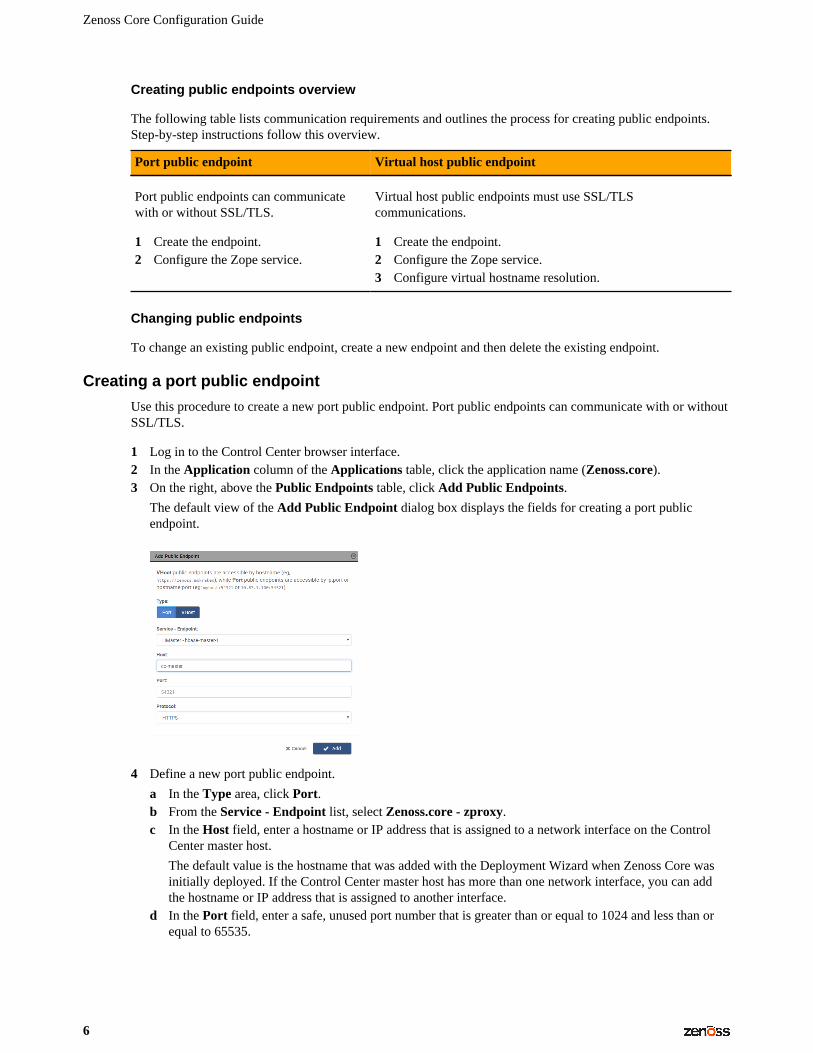
1 Log in to the Control Center browser interface.2 In the Application column of the Applications table, click the application name (Zenoss.core).3 On the right, above the Public Endpoints table, click Add Public Endpoints.
The default view of the Add Public Endpoint dialog box displays the fields for creating a port publicendpoint.
4 Define a new port public endpoint.
a In the Type area, click Port.b From the Service - Endpoint list, select Zenoss.core - zproxy.c In the Host field, enter a hostname or IP address that is assigned to a network interface on the Control
Center master host.
The default value is the hostname that was added with the Deployment Wizard when Zenoss Core wasinitially deployed. If the Control Center master host has more than one network interface, you can addthe hostname or IP address that is assigned to another interface.
d In the Port field, enter a safe, unused port number that is greater than or equal to 1024 and less than orequal to 65535.
Enabling access to browser interfaces
7
For a list of ports that are considered unsafe, see Unsafe ports on Chrome. For the list of ports that theControl Center master host uses, refer to the Zenoss Core Planning Guide.
e In the Protocol field, select HTTPS or HTTP.
Optionally, you can set up a secure proxy server to handle HTTP requests that are sent to a port publicendpoint.
f Click Add.
Next step: Configure the Zope service to use the new port public endpoint. Choose one of the configurationoptions in the following table.
Zope configuration Procedure
HTTPS and the default secure proxy server Configuring Zope for HTTPS and the default secureproxy server on page 7
HTTP and no proxy server
Note that when you configure Zope for HTTPprotocol and no proxy server, you can only gainaccess to the Zenoss Core browser interface throughport public endpoints that are configured for HTTP.Because virtual host public endpoints must useHTTPS protocol, any existing virtual host publicendpoints stop working.
Configuring Zope for HTTP and no proxy server onpage 8
HTTP and a secure proxy server other than the default Configuring Zope for HTTP and a secure proxy serveron page 9
Configuring Zope for HTTPS and the default secure proxy server
Before performing this procedure, create a port public endpoint or a virtual host public endpoint to use theHTTPS protocol.
Use this procedure to configure the Zope service for SSL/TLS communications and the secure proxy server thatis included in Zenoss Core.
1 Log in to the Control Center browser interface.2 In the Application column of the Applications table, click the application name (Zenoss.core).3 In the Services table, expand Zenoss > User Interface, and then click Zope.
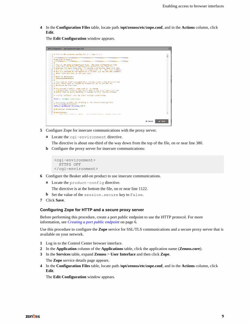
The Zope service details page appears.4 In the Configuration Files table, locate path /opt/zenoss/etc/zope.conf, and in the Actions column, click
Edit.
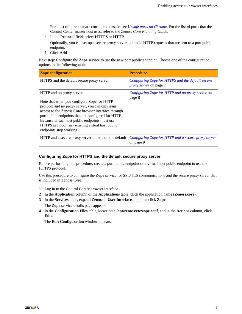
The Edit Configuration window appears.
Zenoss Core Configuration Guide
8
5 Configure Zope for secure communications with the proxy server.
a Locate the cgi-environment directive.
The directive is about one-third of the way down from the top of the file, on or near line 380.b Configure the proxy server for SSL/TLS communications:
<cgi-environment> HTTPS ON</cgi-environment>
6 Configure the Beaker add-on product to use secure communications.
a Locate the product-config directive.
The directive is at the bottom the file, on or near line 1122.b Set the value of the session.secure key to True.
7 Click Save.
Next steps:
■ If you created a port public endpoint before performing this procedure, the endpoint is ready to use.■ If you created a virtual host public endpoint before performing this procedure, proceed to Configuring name
resolution for virtual hosts on page 12.
Configuring Zope for HTTP and no proxy server
Before performing this procedure, create a port public endpoint to use the HTTP protocol. For moreinformation, see Creating a port public endpoint on page 6.
Use this procedure to configure the Zope service for insecure communications with Zenoss Core browserinterface clients.
Note When you configure Zope for insecure communications, existing virtual host public endpoints stopworking.
1 Log in to the Control Center browser interface.2 In the Application column of the Applications table, click the application name (Zenoss.core).3 In the Services table, expand Zenoss > User Interface, and then click Zope.
The Zope service details page appears.
Enabling access to browser interfaces
9
4 In the Configuration Files table, locate path /opt/zenoss/etc/zope.conf, and in the Actions column, clickEdit.
The Edit Configuration window appears.
5 Configure Zope for insecure communications with the proxy server.
a Locate the cgi-environment directive.
The directive is about one-third of the way down from the top of the file, on or near line 380.b Configure the proxy server for insecure communications:
<cgi-environment> HTTPS OFF</cgi-environment>
6 Configure the Beaker add-on product to use insecure communications.
a Locate the product-config directive.
The directive is at the bottom the file, on or near line 1122.b Set the value of the session.secure key to False.
7 Click Save.
Configuring Zope for HTTP and a secure proxy server
Before performing this procedure, create a port public endpoint to use the HTTP protocol. For moreinformation, see Creating a port public endpoint on page 6.
Use this procedure to configure the Zope service for SSL/TLS communications and a secure proxy server that isavailable on your network.
1 Log in to the Control Center browser interface.2 In the Application column of the Applications table, click the application name (Zenoss.core).3 In the Services table, expand Zenoss > User Interface and then click Zope.
The Zope service details page appears.4 In the Configuration Files table, locate path /opt/zenoss/etc/zope.conf, and in the Actions column, click
Edit.
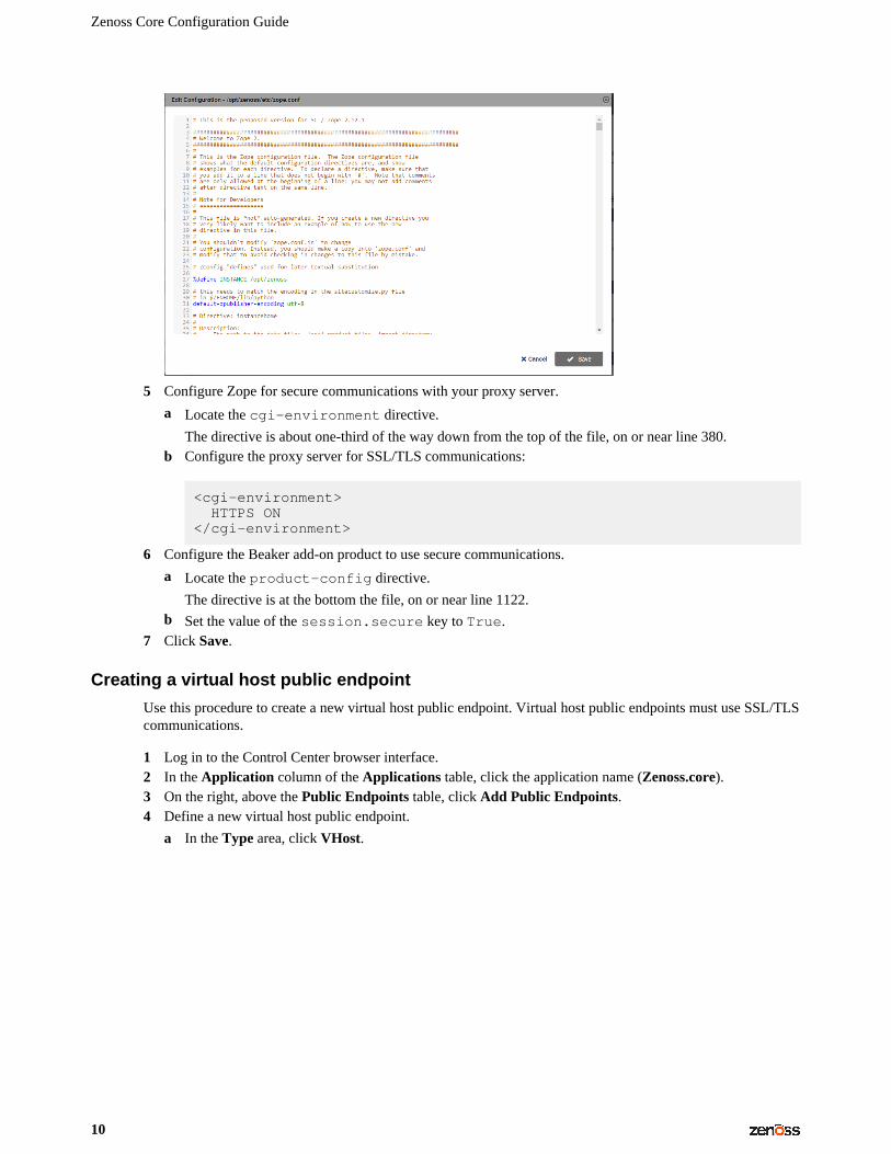
The Edit Configuration window appears.
Zenoss Core Configuration Guide
10
5 Configure Zope for secure communications with your proxy server.
a Locate the cgi-environment directive.
The directive is about one-third of the way down from the top of the file, on or near line 380.b Configure the proxy server for SSL/TLS communications:
<cgi-environment> HTTPS ON</cgi-environment>
6 Configure the Beaker add-on product to use secure communications.
a Locate the product-config directive.
The directive is at the bottom the file, on or near line 1122.b Set the value of the session.secure key to True.
7 Click Save.
Creating a virtual host public endpoint
Use this procedure to create a new virtual host public endpoint. Virtual host public endpoints must use SSL/TLScommunications.
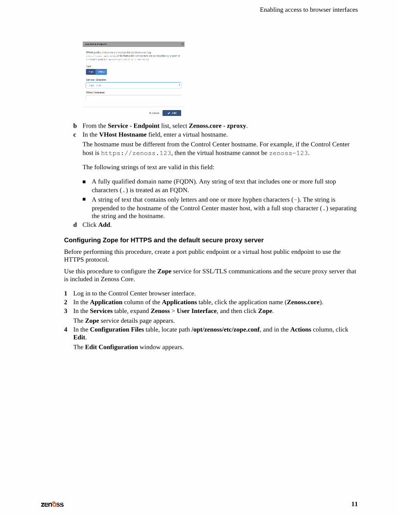
1 Log in to the Control Center browser interface.2 In the Application column of the Applications table, click the application name (Zenoss.core).3 On the right, above the Public Endpoints table, click Add Public Endpoints.4 Define a new virtual host public endpoint.
a In the Type area, click VHost.
Enabling access to browser interfaces
11
b From the Service - Endpoint list, select Zenoss.core - zproxy.c In the VHost Hostname field, enter a virtual hostname.
The hostname must be different from the Control Center hostname. For example, if the Control Centerhost is https://zenoss.123, then the virtual hostname cannot be zenoss-123.
The following strings of text are valid in this field:
■ A fully qualified domain name (FQDN). Any string of text that includes one or more full stopcharacters (.) is treated as an FQDN.
■ A string of text that contains only letters and one or more hyphen characters (-). The string isprepended to the hostname of the Control Center master host, with a full stop character (.) separatingthe string and the hostname.
d Click Add.
Configuring Zope for HTTPS and the default secure proxy server
Before performing this procedure, create a port public endpoint or a virtual host public endpoint to use theHTTPS protocol.
Use this procedure to configure the Zope service for SSL/TLS communications and the secure proxy server thatis included in Zenoss Core.
1 Log in to the Control Center browser interface.2 In the Application column of the Applications table, click the application name (Zenoss.core).3 In the Services table, expand Zenoss > User Interface, and then click Zope.
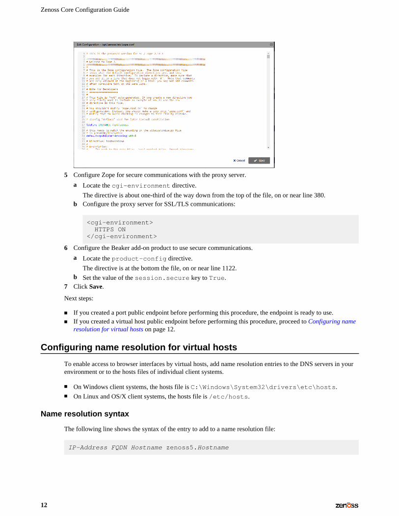
The Zope service details page appears.4 In the Configuration Files table, locate path /opt/zenoss/etc/zope.conf, and in the Actions column, click
Edit.
The Edit Configuration window appears.
Zenoss Core Configuration Guide
12
5 Configure Zope for secure communications with the proxy server.
a Locate the cgi-environment directive.
The directive is about one-third of the way down from the top of the file, on or near line 380.b Configure the proxy server for SSL/TLS communications:
<cgi-environment> HTTPS ON</cgi-environment>
6 Configure the Beaker add-on product to use secure communications.
a Locate the product-config directive.
The directive is at the bottom the file, on or near line 1122.b Set the value of the session.secure key to True.
7 Click Save.
Next steps:
■ If you created a port public endpoint before performing this procedure, the endpoint is ready to use.■ If you created a virtual host public endpoint before performing this procedure, proceed to Configuring name
resolution for virtual hosts on page 12.
Configuring name resolution for virtual hosts
To enable access to browser interfaces by virtual hosts, add name resolution entries to the DNS servers in yourenvironment or to the hosts files of individual client systems.
■ On Windows client systems, the hosts file is C:\Windows\System32\drivers\etc\hosts.■ On Linux and OS/X client systems, the hosts file is /etc/hosts.
Name resolution syntax
The following line shows the syntax of the entry to add to a name resolution file:
IP-Address FQDN Hostname zenoss5.Hostname

Enabling access to browser interfaces
13
For example, the following entry identifies a Control Center master host at IP address 192.0.2.12, hostnamecc-master, in the example.com domain.
192.0.2.12 cc-master.example.com cc-master zenoss5.cc-master
Configuring name resolution on a Windows 7 system
To perform this procedure, you need Windows Administrator privileges.
1 Log in to the Windows 7 system as a user with Administrator privileges.2 Click Start > All Programs > Accessories > Notepad.3 Right click Notepad and then select Run as administrator.4 Click File > Open, and then enter the following file path:
C:\Windows\System32\drivers\etc\hosts
5 At the end of the file, add a name resolution entry.
For more information, see Name resolution syntax on page 12.6 Save the file, and then exit Notepad.
Configuring name resolution on a Linux or OS/X system
To perform this procedure, you need superuser privileges on the client system.
1 Log in to the client system as root or as a user with sudo privileges.2 In a text editor, Open the /etc/hosts file.3 At the end of the file, add a name resolution entry.
For more information, see Name resolution syntax on page 12.4 Save the file, and then close the editor.
Zenoss Core Configuration Guide
14
Configuring Zenoss Core 2This chapter contains configuration procedures that you perform after Zenoss Core is installed. Some of theprocedures are optional, and indicated as such in the section title. For installation and deployment instructions,refer to the Zenoss Core Installation Guide.
Starting Zenoss Core
You can start Zenoss Core from the Control Center browser interface or from the command-line interface.
Using the Control Center browser interface to start Zenoss Core
To perform this procedure, you need:
■ A tested client system and browser■ A user account on the Control Center master host with access privileges for the Control Center browser
interface
For more information, refer to the Zenoss Core Installation Guide.
1 Log in to the Control Center browser interface.
2 In the Actions column of the Applications table, click Start for Zenoss.core.3 In the Start Service dialog box, click Start Service and x Children.4 Optional: Monitor the startup.
a In the Applications table, click Zenoss.core.b Scroll down to the Services table and review the Health icon for each service.
As services start, the Health icon changes to a check mark.
Using the command line to start Zenoss Core
To perform this procedure, you need serviced CLI privileges. For more information, refer to the Zenoss CoreInstallation Guide.
1 Log in to the Control Center master host as a user with serviced CLI privileges.2 Start Zenoss Core:
serviced service start Zenoss.core
Configuring Zenoss Core
15
3 Optional: Monitor the startup:
serviced service status Zenoss.core
Default server passwords
Zenoss Core adds global configuration parameters to the run-time environments (Docker containers) ofevery service. The parameters include the default passwords of a MariaDB database server and a RabbitMQserver. The default passwords are the same in all Zenoss Core distributions. To avoid security issues, Zenossrecommends changing the default passwords of the preceding servers.
Note Changes to global configuration parameters persist across upgrades.
The following list associates the affected servers, their Zenoss Core services, and their account information.
Note The list includes both account names and passwords. Zenoss recommends changing the passwords ofeach account and strongly discourages changing the account names.
MariaDB server for event and model databases
Administrator account:global.conf.zep-admin-user
Administrator password:global.conf.zep-admin-password
Event database user account:global.conf.zep-user
Event database user password:global.conf.zep-password
Administrator account:global.conf.zodb-admin-user
Administrator password:global.conf.zodb-admin-password
Model database user account:global.conf.zodb-user
Model database user password:global.conf.zodb-password
RabbitMQ server
Service: RabbitMQ
User account: global.conf.amqpuser
User password: global.conf.amqppassword
Changing MariaDB passwords
Use this procedure to change the passwords of the MariaDB databases for event and model data.
To perform this procedure, the MariaDB child service of Zenoss Core must be running.
1 Log in to the Control Center master host as root, or as a user with superuser privileges.2 Log in to the Docker container of the MariaDB service as zenoss.
serviced service attach mariadb su - zenoss
3 Change the passwords.
a Start an interactive session.
export TERM=dumb; mysql -u root
Zenoss Core Configuration Guide
16
b Access the administration database.
USE mysql
c Set the password of the root user.Replace New-Password with a new password:
SET PASSWORD FOR 'root'@'127.0.0.1' = PASSWORD('New-Password');SET PASSWORD FOR 'root'@'localhost' = PASSWORD('New-Password');
Record the password for use in a subsequent step.d Update the password of the zenoss user.
Replace New-Password with a new password:
SET PASSWORD FOR 'zenoss'@'127.0.0.1' = PASSWORD('New-Password');SET PASSWORD FOR 'zenoss'@'%' = PASSWORD('New-Password');
Record the password for use in a subsequent step.e Exit the interactive session.
QUIT
The MariaDB server loads the grant tables into memory immediately when account managementstatements like SET PASSWORD are used, so the FLUSH PRIVILEGES statement is not necessary.
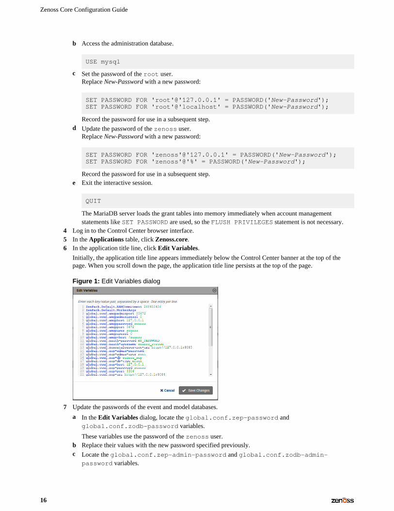
4 Log in to the Control Center browser interface.5 In the Applications table, click Zenoss.core.6 In the application title line, click Edit Variables.
Initially, the application title line appears immediately below the Control Center banner at the top of thepage. When you scroll down the page, the application title line persists at the top of the page.
Figure 1: Edit Variables dialog
7 Update the passwords of the event and model databases.
a In the Edit Variables dialog, locate the global.conf.zep-password andglobal.conf.zodb-password variables.
These variables use the password of the zenoss user.b Replace their values with the new password specified previously.c Locate the global.conf.zep-admin-password and global.conf.zodb-admin-
password variables.
Configuring Zenoss Core
17
These variables use the password of the root user.d Replace their values with the new password specified previously.e At the bottom of the Edit Variables dialog, click Save Changes.
8 Restart Zenoss Core.
a Scroll down to the Services table, and then locate the MariaDB service.b In the application title line, click the Restart control.
Changing the RabbitMQ server password
Use this procedure to change the password of the RabbitMQ server.
To perform this procedure, the mariadb-model child services of Zenoss Core must be running.
1 Log in to the Control Center master host as root, or as a user with superuser privileges.2 Change the password of the zenoss user.
a Log in to the Docker container of the RabbitMQ service as root.
serviced service attach rabbitmq
b Change the password.Replace New-Password with a new password:
rabbitmqctl change_password zenoss New-Password
Record the password for use in a subsequent step.c Log out of the Docker container.
exit
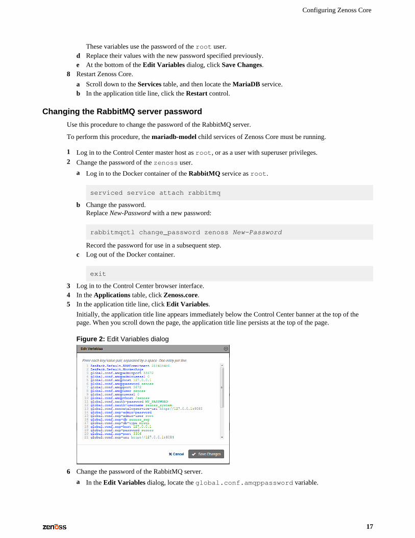
3 Log in to the Control Center browser interface.4 In the Applications table, click Zenoss.core.5 In the application title line, click Edit Variables.
Initially, the application title line appears immediately below the Control Center banner at the top of thepage. When you scroll down the page, the application title line persists at the top of the page.
Figure 2: Edit Variables dialog
6 Change the password of the RabbitMQ server.
a In the Edit Variables dialog, locate the global.conf.amqppassword variable.
Zenoss Core Configuration Guide
18
b Replace its value with the new password specified previously.c At the bottom of the Edit Variables dialog, click Save Changes.
7 Restart the RabbitMQ service.
a Scroll down to the Services table, and then locate the RabbitMQ service.b In the Actions column of the service, click the Restart control.
Deleting the RabbitMQ guest user account
By default, RabbitMQ distributions include the guest user account. To prevent security issues, Zenossrecommends deleting the account.
1 Log in to the Control Center master host as a user with serviced CLI privileges.2 Attach to the RabbitMQ container.
serviced service attach rabbitmq
3 Delete the guest user account.
rabbitmqctl delete_user guest
4 Exit the container session.
exit
5 Restart the RabbitMQ service.
serviced service restart rabbitmq
MariaDB database utilities
The Percona Toolkit is a collection of helpful utilities for MySQL and MariaDB databases. For licensingreasons, Zenoss can not distribute it. Zenoss strongly recommends that all installations of Zenoss Core installthe Percona Toolkit.
Installing the Percona Toolkit with internet access
To perform this procedure, you need one of the following:
■ a login account on the master host that is a member of the docker group■ the password of the root user account
For more information, refer to the Zenoss Core Installation Guide.
1 Log in to the Control Center master host.2 Install the package.
serviced service run zope install-percona
At the end of the installation process, the message Container not commited appears. This is normal.The tools are installed in the distributed file system, not in an image.
Configuring Zenoss Core
19
Installing the Percona Toolkit without internet access
To perform this procedure, you need one of the following:
■ a login account on the master host that is a member of the docker group■ the password of the root user account
In addition, you need the Percona Toolkit package file. This procedure includes steps for downloading it to aclient system, and then copying it to the Control Center master host.
1 On a client system, use a web browser to download the latest version of the Percona Toolkit package.2 Log in to the Control Center master host.3 Prepare the package for installation.
a On the Control Center master host, create a directory for the package, and then change directory.
mkdir /tmp/percona && cd /tmp/percona
b Copy the package to the temporary location.
You may use a file transfer utility such as WinSCP.c Update the access permissions of the file and directory.
chmod -R 777 /tmp/percona
4 Start a shell as the zenoss user in a Zope container.
a Change directory to the location of the Percona Toolkit file.
cd /tmp/percona
b Start an interactive shell in a Zope container and save a snapshot named PerconaToolkit.
mySnap=InstallPerconaToolkitserviced service shell -i -s $mySnap zope bash
c Switch user to zenoss.
su - zenoss
5 Install the package and exit the Zope container.
a Create a directory for the package.
PERCONADIR=/var/zenoss/perconamkdir -p $PERCONADIR
b Extract the package files.
Replace Version with the version number of the package file:
tar --strip-components=1 -C $PERCONADIR -xzvf \ /mnt/pwd/percona-toolkit-Version.tar.gz
c Exit the zenoss shell.
exit
Zenoss Core Configuration Guide
20
d Exit the Zope container.
exit
6 Commit the named snapshot.
serviced snapshot commit $mySnap
7 Restart the zeneventserver service.
serviced service restart zeneventserver
Optional: Assigning a virtual IP address to a resource poolThe zentrap and zensyslog services are designed to receive data from devices in your environment at a specificIP address. Typically, the address is assigned to a specific host. However, if the host fails, then no data isreceived. To avoid this issue, you can assign a virtual IP address to a resource pool, and then Control Center cancreate a virtual IP interface on any host in the pool. Zenoss recommends using a virtual IP with resource poolsthat include Zenoss Core collection services as a best practice.
To perform this procedure, you need an unused IPv4 address in the same subnet as the other hosts in theresource pool to modify. To avoid conflicts, ask your networking specialist to assign or reserve the address. Inaddition, all of the hosts in the resource pool to modify must have the same network interface names.
1 Log in to the Control Center browser interface.2 At the top of the page, click Resource Pools.3 In the Resource Pool column of the Resource Pools table, click the name of the resource pool to modify.4 At the right side of the Virtual IPs table, click Add Virtual IP.5 In the Add Virtual IP dialog, specify the virtual IP.
a In the IP field, enter an IPv4 address.
The address must be in the same subnet as the other hosts in the current resource pool.b In the Netmask field, enter an IPv4 subnet mask.
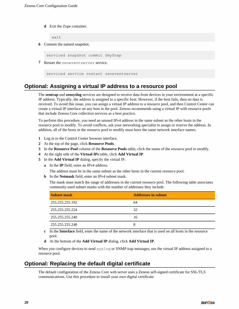
The mask must match the range of addresses in the current resource pool. The following table associatescommonly-used subnet masks with the number of addresses they include.
Subnet mask Addresses in subnet
255.255.255.192 64
255.255.255.224 32
255.255.255.240 16
255.255.255.248 8
c In the Interface field, enter the name of the network interface that is used on all hosts in the resourcepool.
d At the bottom of the Add Virtual IP dialog, click Add Virtual IP.
When you configure devices to send syslog or SNMP trap messages, use the virtual IP address assigned to aresource pool.
Optional: Replacing the default digital certificateThe default configuration of the Zenoss Core web server uses a Zenoss self-signed certificate for SSL/TLScommunications. Use this procedure to install your own digital certificate.
Configuring Zenoss Core
21
To perform this procedure, you need:
■ the certificate and key files of a digital certificate from a certificate authority or from a digital certificatecreated with a utility such as OpenSSL
Note Certificates that require a passphrase are not supported.
■ superuser privileges on the Control Center master host
1 Log in to the Control Center master host.2 Copy the certificate and key files of your digital certificate to /etc on the master host.
You can store the files in any location that remains unchanged during operating system upgrades.3 Configure Control Center to use your digital certificate.
a Open /etc/default/serviced with a text editor.b Locate the SERVICED_CERT_FILE declaration, and then replace its value with the absolute path of your
certificate file.c Remove the number sign character (#) from the beginning of the line.d Locate the SERVICED_KEY_FILE declaration, and then replace its value with the absolute path of your
key file.e Remove the number sign character (#) from the beginning of the line.f Save the file, and then close editor.
4 Reload the Control Center service.
systemctl reload serviced
Optional: Enabling monitoring on IPv6 networksThis procedure describes how to configure Zenoss Core to enable monitoring of devices that are located on anIPv6 network. The network must be reachable from the IPv4 network environment in which Control Center isdeployed.
Use this procedure to route an IPv6 address block to Control Center using Docker's virtual bridge interface,docker0. Zenoss Core can monitor IPv6 devices that have addresses in the routed block.
To perform this procedure, each Control Center host needs a unique IPv6 prefix routed to it by an upstreamrouter, and the Docker service on Control Center host needs to be configured to forward IPv6 packets.
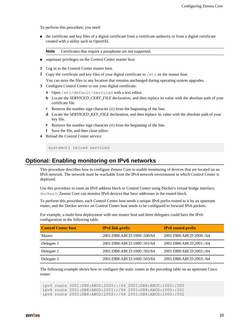
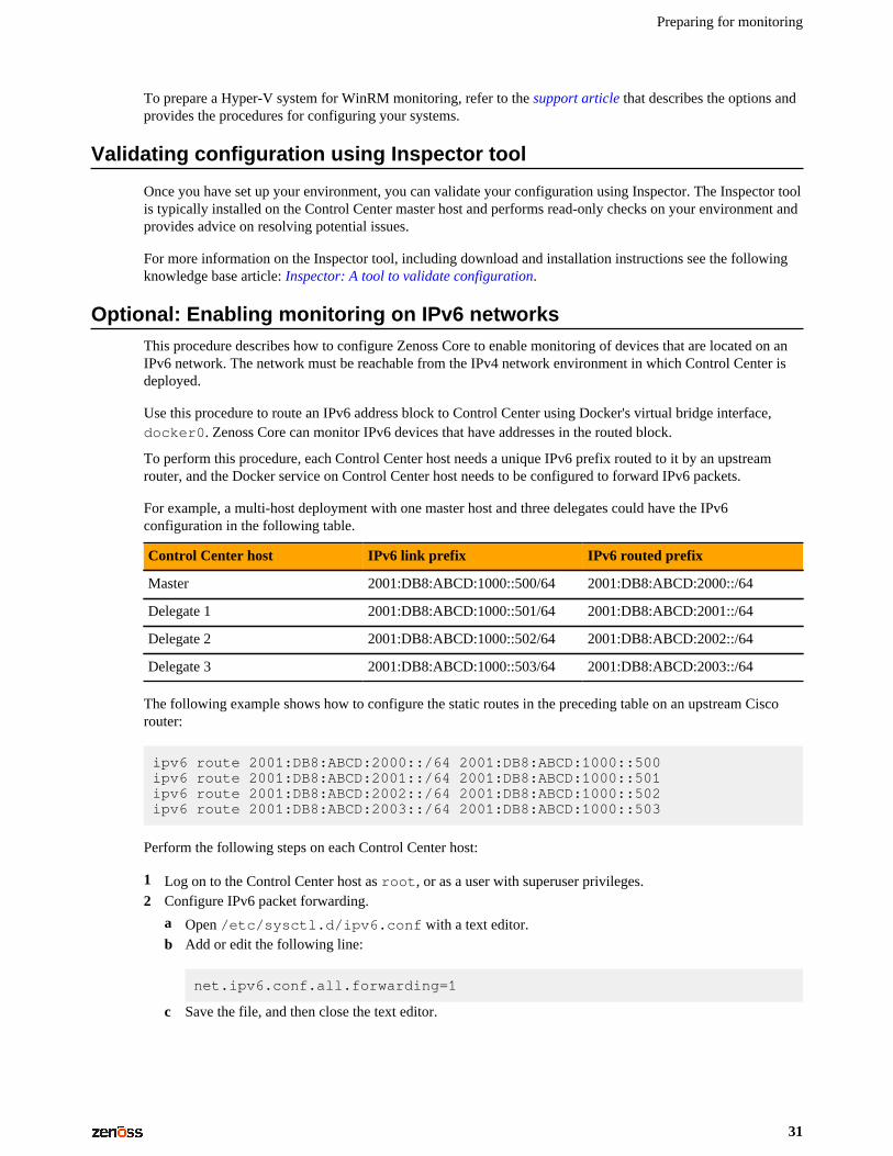
For example, a multi-host deployment with one master host and three delegates could have the IPv6configuration in the following table.
Control Center host IPv6 link prefix IPv6 routed prefix
Master 2001:DB8:ABCD:1000::500/64 2001:DB8:ABCD:2000::/64
Delegate 1 2001:DB8:ABCD:1000::501/64 2001:DB8:ABCD:2001::/64
Delegate 2 2001:DB8:ABCD:1000::502/64 2001:DB8:ABCD:2002::/64
Delegate 3 2001:DB8:ABCD:1000::503/64 2001:DB8:ABCD:2003::/64
The following example shows how to configure the static routes in the preceding table on an upstream Ciscorouter:
ipv6 route 2001:DB8:ABCD:2000::/64 2001:DB8:ABCD:1000::500ipv6 route 2001:DB8:ABCD:2001::/64 2001:DB8:ABCD:1000::501ipv6 route 2001:DB8:ABCD:2002::/64 2001:DB8:ABCD:1000::502
Zenoss Core Configuration Guide
22
ipv6 route 2001:DB8:ABCD:2003::/64 2001:DB8:ABCD:1000::503
Perform the following steps on each Control Center host:
1 Log on to the Control Center host as root, or as a user with superuser privileges.2 Configure IPv6 packet forwarding.
a Open /etc/sysctl.d/ipv6.conf with a text editor.b Add or edit the following line:
net.ipv6.conf.all.forwarding=1
c Save the file, and then close the text editor.3 Enable IPv6 packet forwarding without rebooting the host.
sysctl -w net.ipv6.conf.all.forwarding=1
4 Configure Docker for IPv6 communications.
a Open /etc/sysconfig/docker with a text editor.b Add the following flags to the end of the OPTIONS declaration.
Replace Subnet-Block with the IPv6 subnet to route to Control Center, in CIDR notation:
--ipv6 --fixed-cidr-v6="Subnet-Block"
c Change the delimiter of the OPTIONS declaration to the apostrophe character (').
The default delimiter of the OPTIONS declaration is the quotation mark character ("), which is the samedelimiter used with the --fixed-cidr-ipv6 flag.
d Save the file, and then close the text editor.5 Restart the Docker service.
systemctl restart docker
After all Control Center hosts are configured, test IPv6 by using the Docker container of the zenping service toping a known address:
serviced service attach zenping ping6 -c 1 ipv6.google.com
If the ping is successful, Docker is able to resolve IPv6 addresses and you can monitor devices on the IPv6network.
Optional: Customization management
Zenoss Core software is distributed as Docker images. Upgrades often replace images, so customizations ofZenoss Core services are lost, unless customizations are installed with a change management system.
Quilt is a utility for managing software changes, and Zenoss recommends installing it to managecustomizations.
Installing Quilt with internet access
To perform this procedure, you need superuser privileges on the Control Center master host.
Use this procedure to add the Quilt patch management system to Zenoss Core.
Configuring Zenoss Core
23
1 Log in to the Control Center master host.2 Install the Quilt package.
serviced service run zope install-quilt
Installing Quilt without internet access
To perform this procedure, you need superuser privileges on the Control Center master host and the Quiltpackage file. This procedure includes steps for downloading the package to a client system, and then copying itto the Control Center master host.
Use this procedure to add the Quilt patch management system to Zenoss Core.
1 On a client system, use a web browser to download the latest version of the Quilt package.2 Log in to the Control Center master host.3 Prepare the package for installation.
a On the Control Center master host, create a directory for the package, and then change directory.
mkdir /tmp/quilt && cd /tmp/quilt
b Copy the package to the temporary location.
You may use a file transfer utility such as WinSCP.c Update the access permissions of the file and directory.
chmod -R 777 /tmp/quilt
4 Start a shell as the zenoss user in a Zope container.
a Change directory to the location of the Quilt package file.
cd /tmp/quilt
b Start an interactive shell in a Zope container and save a snapshot named InstallQuilt.
mySnap=InstallQuiltserviced service shell -i -s $mySnap zope bash
c Switch user to zenoss.
su - zenoss
5 Extract the package files, and then compile and install Quilt.
a Extract the package files.
tar xzvf /mnt/pwd/quilt-*.tar.gz -C /tmp
b Compile and install the package.
cd /tmp/quilt-* && ./configure --prefix=/opt/zenoss/var/ext \ && make && make install
6 Exit the container.
a Exit the zenoss shell.
exit
Zenoss Core Configuration Guide
24
b Exit the Zope container.
exit
7 Commit the named snapshot.
serviced snapshot commit $mySnap
Optional: Configuring OpenTSDB compactionZenoss Core uses OpenTSDB to store the monitoring data it collects. When OpenTSDB compaction is enabled,multiple columns in an HBase row are merged into a single column, to reduce disk space. In testing, Zenoss hasobserved that these merges result in duplicate data points, so by default, compaction is disabled. Duplicate datapoints do not affect data integrity.
Note Enabling compaction slows performance and is not recommended.
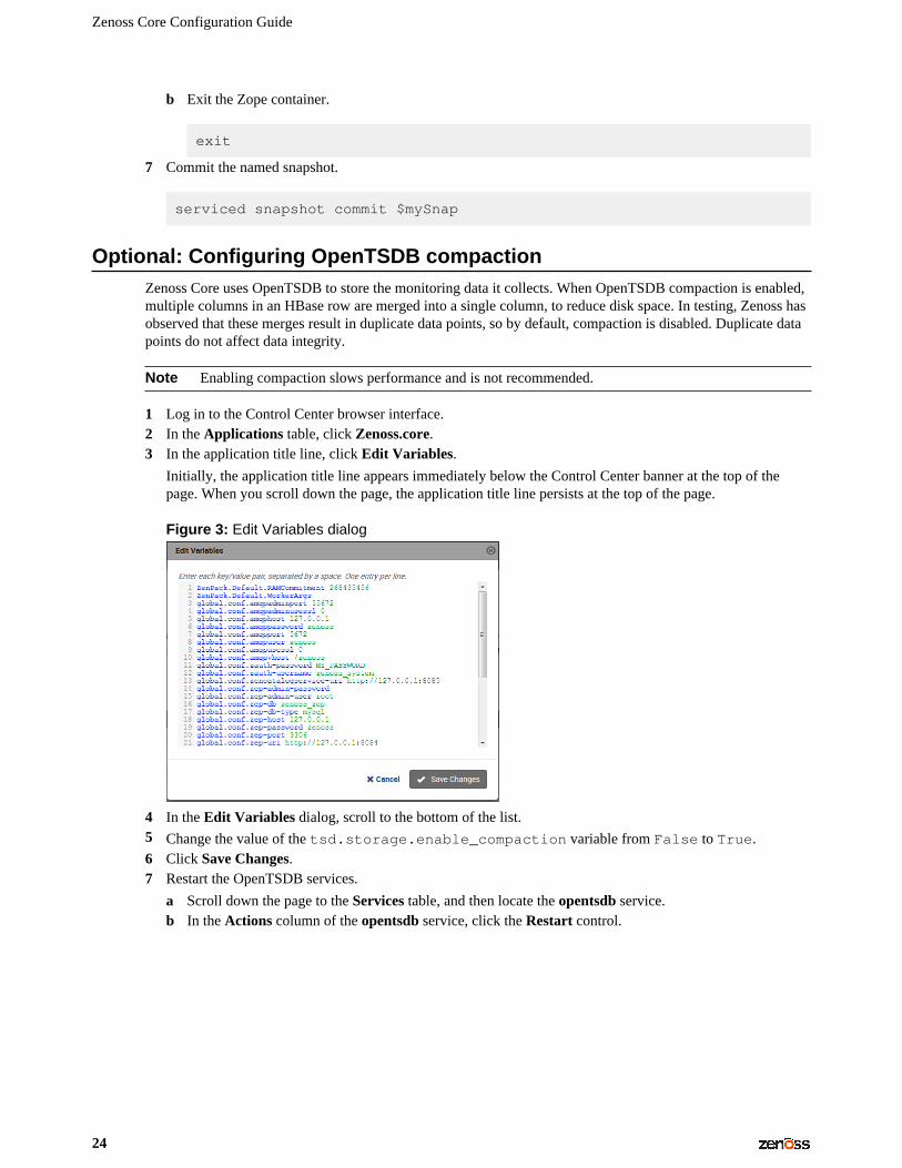
1 Log in to the Control Center browser interface.2 In the Applications table, click Zenoss.core.3 In the application title line, click Edit Variables.
Initially, the application title line appears immediately below the Control Center banner at the top of thepage. When you scroll down the page, the application title line persists at the top of the page.
Figure 3: Edit Variables dialog
4 In the Edit Variables dialog, scroll to the bottom of the list.5 Change the value of the tsd.storage.enable_compaction variable from False to True.6 Click Save Changes.7 Restart the OpenTSDB services.
a Scroll down the page to the Services table, and then locate the opentsdb service.b In the Actions column of the opentsdb service, click the Restart control.
Preparing for monitoring
25
Preparing for monitoring 3Zenoss Core uses standard management APIs to collect performance data, and therefore does not installproprietary agents on your infrastructure devices to collect monitoring data. However, Zenoss recommends thatyou review the information in this chapter to verify that the devices to you want to monitor are ready to respondto requests for data.
Note This chapter describes how to prepare the most common IT infrastructure. If the infrastructure youwant to monitor is not described here, please refer to the corresponding ZenPack documentation in the ZenPackcatalog.
When your infrastructure is ready to monitor, the Zenoss Core Setup Wizard guides you through the process ofdiscovering devices on your network and adding devices by category and type.
Extending monitoring with ZenPacks
Data centers typically contain many different types of hardware, software, and cloud services from a longlist vendors. To keep your company's data secure, all devices, network infrastructure, and services must bemonitored.
Zenoss Core is ready to monitor a large number of common devices and network infrastructure as soon itis installed. However, you can monitor an even larger number of devices in Zenoss Core through the use ofZenPacks. A ZenPack is a plug-in that extends not only monitoring capabilities, but also adds new capabilitiesto the Zenoss Core itself. This can be as simple as adding new device classes or monitoring templates, or ascomplex as extending the data model and providing new collection daemons.
There are hundreds of ZenPacks available, some developed, supported, and maintained by Zenoss, and manyothers that are developed and maintained by the Zenoss user community.
You can use ZenPacks to add:
■ Monitoring templates■ Data sources■ Graphs■ Event classes■ User commands■ Reports■ Model extensions■ Product definitions
Zenoss Core Configuration Guide
26
Simple ZenPacks can be created completely within the Zenoss Core. More complex ZenPacks requiredevelopment of scripts or daemons, using Python or another programming language. ZenPacks can also bedistributed for installation on other Zenoss Core systems. For information on how to create a new ZenPack,refer to Zenoss Core Administration Guide.
ZenPack information resources
Zenoss Core includes a link (the question mark icon) to the documentation for ZenPacks that are includedin your installation of Zenoss Core. It also provides access to the ZenPack catalog, which provides detaileddescriptions of all ZenPacks that Zenoss developes.
You can also create your own ZenPacks, or download and install ZenPacks developed by others. The followinglist identifies ZenPack resources:
■ ZenPack SDK■ Zenoss Community, which includes a ZenPack development forum■ Public Zenoss repositories on GitHub
Displaying installed ZenPacks in Zenoss Core
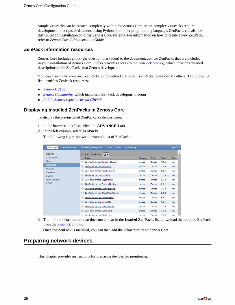
To display the pre-installed ZenPacks on Zenoss Core:
1 In the browser interface, select the ADVANCED tab.2 In the left column, select ZenPacks.
The following figure shows an example list of ZenPacks.
3 To monitor infrastructure that does not appear in the Loaded ZenPacks list, download the required ZenPackfrom the ZenPack catalog.
Once the ZenPack is installed, you can then add the infrastructure to Zenoss Core.
Preparing network devices
This chapter provides instructions for preparing devices for monitoring.
Preparing for monitoring
27
Preparing switches and routers
To prepare a switch or router device for monitoring, verify that an SNMP agent is installed and currentlyrunning on the device.
Note This rest of this section describes how to prepare Zenoss network devices for monitoring. For otherdevice types, refer to the ZenPack catalog documentation.
Preparing Cisco UCS network devices
Zenoss Core uses SNMP to provide customized or generalized support for many Zenoss products.
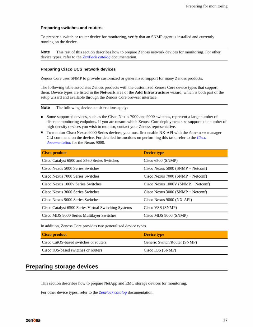
The following table associates Zenoss products with the customized Zenoss Core device types that supportthem. Device types are listed in the Network area of the Add Infrastructure wizard, which is both part of thesetup wizard and available through the Zenoss Core browser interface.
Note The following device considerations apply:
■ Some supported devices, such as the Cisco Nexus 7000 and 9000 switches, represent a large number ofdiscrete monitoring endpoints. If you are unsure which Zenoss Core deployment size supports the number ofhigh-density devices you wish to monitor, contact your Zenoss representative.
■ To monitor Cisco Nexus 9000 Series devices, you must first enable NX-API with the feature managerCLI command on the device. For detailed instructions on performing this task, refer to the Ciscodocumentation for the Nexus 9000.
Cisco product Device type
Cisco Catalyst 6500 and 3560 Series Switches Cisco 6500 (SNMP)
Cisco Nexus 5000 Series Switches Cisco Nexus 5000 (SNMP + Netconf)
Cisco Nexus 7000 Series Switches Cisco Nexus 7000 (SNMP + Netconf)
Cisco Nexus 1000v Series Switches Cisco Nexus 1000V (SNMP + Netconf)
Cisco Nexus 3000 Series Switches Cisco Nexus 3000 (SNMP + Netconf)
Cisco Nexus 9000 Series Switches Cisco Nexus 9000 (NX-API)
Cisco Catalyst 6500 Series Virtual Switching Systems Cisco VSS (SNMP)
Cisco MDS 9000 Series Multilayer Switches Cisco MDS 9000 (SNMP)
In addition, Zenoss Core provides two generalized device types.
Cisco product Device type
Cisco CatOS-based switches or routers Generic Switch/Router (SNMP)
Cisco IOS-based switches or routers Cisco IOS (SNMP)
Preparing storage devices
This section describes how to prepare NetApp and EMC storage devices for monitoring.
For other device types, refer to the ZenPack catalog documentation.
Zenoss Core Configuration Guide
28
Legacy NetApp filers
Zenoss Core uses SNMP to monitor legacy NetApp filers that do not support the Data ONTAP® API (ZAPI).
The data gathered are approximate because the values for many objects (Aggregate, Volume, Plex, and RAIDgroup) are not exposed by the NetApp MIB.
To prepare a legacy NetApp filer for monitoring, verify that SNMPv2 is installed, and then start an SNMPagent.
Recent NetApp filers
Zenoss Core uses HTTP to monitor NetApp filers that support the Data ONTAP® API (ZAPI).
To prepare a recent NetApp filers for monitoring, verify the following conditions:
■ The filer is running in 7-Mode or C-Mode.■ A supported version of ZAPI is installed and enabled. The minimum required version is 8.x.■ The user name and password of your account on the filer is authorized to use ZAPI.
EMC storage arrays
Zenoss Core uses the Web-Based Enterprise Management (WBEM) protocol to send queries to EMC StorageManagement Initiative Specification (SMI-S) providers that are associated with EMC VMAX and VNX storagearrays.
To prepare EMC arrays for monitoring:
■ At least one EMC SMI-S provider must be running for each type of array to monitor. (The VMAX and VNXdata models are different.)
■ Before adding an SMI-S provider to Zenoss Core, Zenoss recommends that you confirm that it is respondingto requests.
■ You need the following information:
■ user name and password for an account that is authorized to collect data on each SMI-S provider■ IP address of each SMI-S provider■ port number at which each SMI-S provider listens for requests■ whether to use SSL
Note When statistics logging is disabled on the EMC device, graphs for component types of EMC arraysdisplay NaN. The logging feature has a low default timeout value and must be set to a higher value or turned onagain periodically.
Verifying an SMI-S provider on EMC devices
To perform this procedure, you need a Linux host that has a network path to the SMI-S providers of the arraysto monitor.
Note Do not perform this procedure on the Zenoss Core host.
Perform this procedure to verify that the SMI-S providers associated with EMC arrays are configured correctly,and are responding to WBEM queries from command line tools.
1 Log in to a Linux host as root, or as a user with superuser privileges.2 Install a WBEM command-line interface package, such as wbemcli.
Preparing for monitoring
29
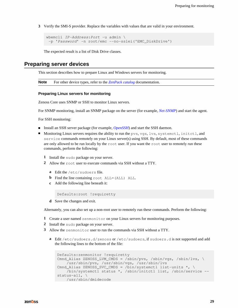
3 Verify the SMI-S provider. Replace the variables with values that are valid in your environment.
wbemcli IP-Address:Port -u admin \ -p 'Password' -n root/emc --no-sslei('EMC_DiskDrive')
The expected result is a list of Disk Drive classes.
Preparing server devicesThis section describes how to prepare Linux and Windows servers for monitoring.
Note For other device types, refer to the ZenPack catalog documentation.
Preparing Linux servers for monitoring
Zenoss Core uses SNMP or SSH to monitor Linux servers.
For SNMP monitoring, install an SNMP package on the server (for example, Net-SNMP) and start the agent.
For SSH monitoring:
■ Install an SSH server package (for example, OpenSSH) and start the SSH daemon.■ Monitoring Linux servers requires the ability to run the pvs, vgs, lvs, systemctl, initctl, and
service commands remotely on your Linux server(s) using SSH. By default, most of these commandsare only allowed to be run locally by the root user. If you want the root user to remotely run thesecommands, perform the following:
1 Install the sudo package on your server.2 Allow the root user to execute commands via SSH without a TTY.
a Edit the /etc/sudoers file.b Find the line containing root ALL=(ALL) ALL.c Add the following line beneath it:
Defaults:root !requiretty
d Save the changes and exit.
Alternately, you can also set up a non-root user to remotely run these commands. Perform the following:
1 Create a user named zenmonitor on your Linux servers for monitoring purposes.2 Install the sudo package on your server.3 Allow the zenmonitor user to run the commands via SSH without a TTY.
a Edit /etc/sudoers.d/zenoss or /etc/sudoers, if sudoers.d is not supported and addthe following lines to the bottom of the file:
Defaults:zenmonitor !requirettyCmnd_Alias ZENOSS_LVM_CMDS = /sbin/pvs, /sbin/vgs, /sbin/lvs, \ /usr/sbin/pvs, /usr/sbin/vgs, /usr/sbin/lvsCmnd_Alias ZENOSS_SVC_CMDS = /bin/systemctl list-units *, \ /bin/systemctl status *, /sbin/initctl list, /sbin/service --status-all, \ /usr/sbin/dmidecode
Zenoss Core Configuration Guide
30
zenmonitor ALL=(ALL) NOPASSWD: ZENOSS_LVM_CMDS, ZENOSS_SVC_CMDS
b Save the changes, ensuring all the paths for these commands are correct.
Preparing Windows servers for monitoring
Zenoss Core uses SNMP or WinRM to monitor Microsoft Windows systems as follows:
■ Microsoft Windows Server 2106 - WinRM only.
SNMP support does not exist for Windows Server 2106.■ Microsoft Windows Server 2012 and 2012 R2 - WinRM only.
SNMP support does not exist for Windows Server 2012 .■ Microsoft Windows Server 2008 R2 - SNMP v1/v2 or WinRM.
SNMP v3 support does not exist for Windows Server 2008 R2.
To prepare a Windows 2008 system for SNMP monitoring, start the SNMP service.
To prepare a Windows system for WinRM monitoring, refer to the support article that describes the options andprovides the procedures for configuring your systems.
To prepare a Windows system for WinRM monitoring, refer to the appendix, "Preparing Windows Systems."
Preparing hypervisor devicesThis section describes how to prepare vSphere and Hyper-V hypervisors for monitoring.
Note For other device types, refer to the ZenPack catalog documentation.
vSphere endPoint
Zenoss Core uses SOAP to monitor VMware vSphere servers running the following versions of vSphere:
■ 4.1■ 5.0■ 5.1■ 5.5■ 6.0
To prepare to monitor a VMware vSphere server:
■ Verify that you are running a supported version of the software.■ Obtain the user name and password of an account on the server that is authorized to use the vSphere API.■ Determine whether to use SSL.
Hyper-V
Zenoss Core uses WinRM to monitor the following Microsoft Hyper-V systems:
■ Microsoft Hyper-V Server 2016■ Microsoft Hyper-V Server 2012 and 2012 R2■ Microsoft Hyper-V Server 2008 and 2008 R2
Preparing for monitoring
31
To prepare a Hyper-V system for WinRM monitoring, refer to the support article that describes the options andprovides the procedures for configuring your systems.
Validating configuration using Inspector tool
Once you have set up your environment, you can validate your configuration using Inspector. The Inspector toolis typically installed on the Control Center master host and performs read-only checks on your environment andprovides advice on resolving potential issues.
For more information on the Inspector tool, including download and installation instructions see the followingknowledge base article: Inspector: A tool to validate configuration.
Optional: Enabling monitoring on IPv6 networksThis procedure describes how to configure Zenoss Core to enable monitoring of devices that are located on anIPv6 network. The network must be reachable from the IPv4 network environment in which Control Center isdeployed.
Use this procedure to route an IPv6 address block to Control Center using Docker's virtual bridge interface,docker0. Zenoss Core can monitor IPv6 devices that have addresses in the routed block.
To perform this procedure, each Control Center host needs a unique IPv6 prefix routed to it by an upstreamrouter, and the Docker service on Control Center host needs to be configured to forward IPv6 packets.
For example, a multi-host deployment with one master host and three delegates could have the IPv6configuration in the following table.
Control Center host IPv6 link prefix IPv6 routed prefix
Master 2001:DB8:ABCD:1000::500/64 2001:DB8:ABCD:2000::/64
Delegate 1 2001:DB8:ABCD:1000::501/64 2001:DB8:ABCD:2001::/64
Delegate 2 2001:DB8:ABCD:1000::502/64 2001:DB8:ABCD:2002::/64
Delegate 3 2001:DB8:ABCD:1000::503/64 2001:DB8:ABCD:2003::/64
The following example shows how to configure the static routes in the preceding table on an upstream Ciscorouter:
ipv6 route 2001:DB8:ABCD:2000::/64 2001:DB8:ABCD:1000::500ipv6 route 2001:DB8:ABCD:2001::/64 2001:DB8:ABCD:1000::501ipv6 route 2001:DB8:ABCD:2002::/64 2001:DB8:ABCD:1000::502ipv6 route 2001:DB8:ABCD:2003::/64 2001:DB8:ABCD:1000::503
Perform the following steps on each Control Center host:
1 Log on to the Control Center host as root, or as a user with superuser privileges.2 Configure IPv6 packet forwarding.
a Open /etc/sysctl.d/ipv6.conf with a text editor.b Add or edit the following line:
net.ipv6.conf.all.forwarding=1
c Save the file, and then close the text editor.
Zenoss Core Configuration Guide
32
3 Enable IPv6 packet forwarding without rebooting the host.
sysctl -w net.ipv6.conf.all.forwarding=1
4 Configure Docker for IPv6 communications.
a Open /etc/sysconfig/docker with a text editor.b Add the following flags to the end of the OPTIONS declaration.
Replace Subnet-Block with the IPv6 subnet to route to Control Center, in CIDR notation:
--ipv6 --fixed-cidr-v6="Subnet-Block"
c Change the delimiter of the OPTIONS declaration to the apostrophe character (').
The default delimiter of the OPTIONS declaration is the quotation mark character ("), which is the samedelimiter used with the --fixed-cidr-ipv6 flag.
d Save the file, and then close the text editor.5 Restart the Docker service.
systemctl restart docker
After all Control Center hosts are configured, test IPv6 by using the Docker container of the zenping service toping a known address:
serviced service attach zenping ping6 -c 1 ipv6.google.com
If the ping is successful, Docker is able to resolve IPv6 addresses and you can monitor devices on the IPv6network.
Modeling devices
33
Modeling devices 4To model devices, the system can use
■ SSH■ WinRM■ SNMP (legacy option)
Note SSH and WinRM are the recommended options.
The modeling method that you select depends on your environment and the types of devices that you want tomodel and monitor.
By default the system remodels each known device every 720 minutes (12 hours).
Note You can change the frequency with which devices are remodeled. Edit the value of the Modeler CycleInterval in the collector's configuration.
For larger deployments, modeling frequency might affect performance. In such environments, set the startatconfiguration setting inside the zenmodeler.conf file to change the scheduling of the daemon. Thestartat value only dictates the initial start time of zenmodeler. Each subsequent run interval is determinedby the zenmodeler cycle time (number of minutes between runs). The cycle time is configured on thedaemon settings page inside the parent's collector folder, which you can access in Control Center. For moreinformation, see KB article How To Edit The Zenmodeler File To Configure Model Scheduling In Zenoss 5.x(also applies to later versions).
Configuring Windows devices to provide data through SNMPTo monitor Microsoft Windows Server 2008 R2 systems, Zenoss Core uses SNMP v1/v2 or WinRM. (There isno SNMP v3 support.) For Windows 2012, there is no SNMP support.
By default, Windows may not have SNMP installed. To install SNMP on your particular version of Windows,please refer to the Microsoft documentation.
After setting up and configuring the SNMP service, you must set the zSnmpCommunity string in Zenoss Core tomatch, to obtain SNMP data.
If you want processor and memory monitoring, install SNMP-Informant on the device.
Zenoss Core Configuration Guide
34
Configuring Linux devices to provide data through SNMP
To configure a Linux machine for monitoring, it must have SNMP installed. A good Linux SNMP application isnet-snmp. Download, install, and configure net-snmp to then use SNMP to monitor Linux devices.
Modeling devices using SSH/COMMAND
You can gather additional information by running commands on the remote device and interpreting the results.This provides a more scalable and flexible way to gather information that may not be available through anyother means.
Each built-in modeling command plugin is differentiated by the platform on which it runs. To determine theplatform for the device you want to model, run the uname command in a shell on the device.
To model a device using command plugins, first add the device by using the protocol "none," and then choosethe plugins you want to apply:
1 From the Navigation menu, select Infrastructure.2 Click the Add Devices icon and select Add a Single Device from the drop-down list. The Add a Single
Device window appears.3 Enter values for Name or IP and Device Class.4 Clear the Model Device option.5 Click Add.6 After adding the device, select the device name in the devices list. The Device Overview page appears.7 In the left panel, select Configuration Properties.8 If necessary, set the values of the zCommandUsername and zCommandPassword configuration properties to
the user name and password of the device (or set up authentication by using RSA/DSA keys.)
Note ~/.ssh/id_rsa
9 In the left panel, select Modeler Plugins. The list of plugins appears. The left column displays availableplugins; the right column shows those currently selected.
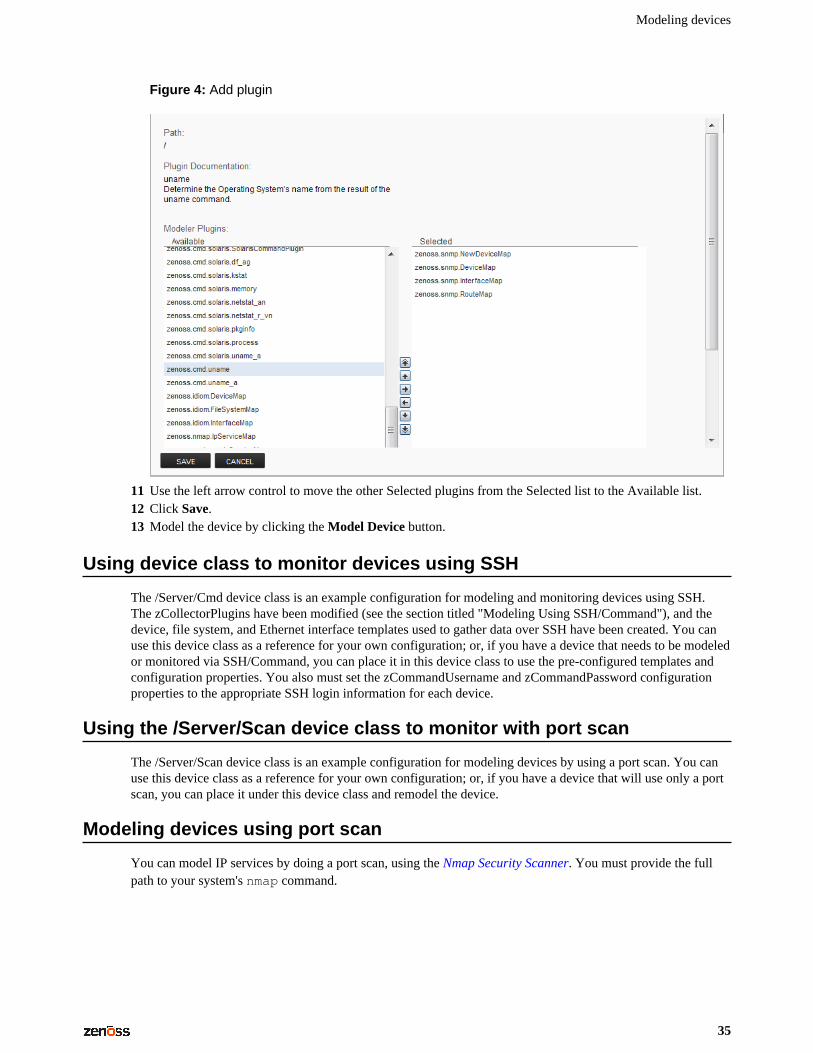
10 Select zenoss.cmd.uname from the Available list, and then use the right arrow control to move it to theSelected list on the right. Use the controls to place it at the top of the list.
Modeling devices
35
Figure 4: Add plugin
11 Use the left arrow control to move the other Selected plugins from the Selected list to the Available list.12 Click Save.13 Model the device by clicking the Model Device button.
Using device class to monitor devices using SSH
The /Server/Cmd device class is an example configuration for modeling and monitoring devices using SSH.The zCollectorPlugins have been modified (see the section titled "Modeling Using SSH/Command"), and thedevice, file system, and Ethernet interface templates used to gather data over SSH have been created. You canuse this device class as a reference for your own configuration; or, if you have a device that needs to be modeledor monitored via SSH/Command, you can place it in this device class to use the pre-configured templates andconfiguration properties. You also must set the zCommandUsername and zCommandPassword configurationproperties to the appropriate SSH login information for each device.
Using the /Server/Scan device class to monitor with port scan
The /Server/Scan device class is an example configuration for modeling devices by using a port scan. You canuse this device class as a reference for your own configuration; or, if you have a device that will use only a portscan, you can place it under this device class and remodel the device.
Modeling devices using port scan
You can model IP services by doing a port scan, using the Nmap Security Scanner. You must provide the fullpath to your system's nmap command.
Zenoss Core Configuration Guide
36
To determine where nmap is installed, at the command line, enter:
which nmap
If your system returns a result similar to:
/usr/bin/which: no nmap in (/opt/zenoss/bin:/usr/kerberos/bin:/usr/local/bin:/bin:/usr/bin:/opt/zenoss/bin)
then nmap is not installed. Install it, and then try again.
After locating the nmap command (including the directory beginning with /), enter the following as thezenoss user on the Zenoss Core server:
cd $ZENHOME/libexec ln -s Full_Path_to_nmap
Note To execute a command using $ZENHOME (/opt/zenoss for the zenoss user), you must be attachedto the container holding the Zenoss Core application. See the Control Center documentation for servicedcommands.
To model a device using a port scan:
1 Select the device in the device list.2 In the left panel, select Modeler Plugins.3 Select the zenoss.nmap.ipServiceMap plugin in the list of Available plugins, and then use the right
arrow control to move it to the list of Selected plugins.4 Click Save.5 Remodel the device by clicking the Model Device button.
About modeler plugins
Zenoss Core uses plug-in maps to map real world information into the standard model. Input to the plug-ins cancome from SNMP, SSH or Telnet. Selection of plug-ins to run against a device is done by matching the plug-inname against the zCollectorPlugins configuration property.
■ DeviceMap– Collects basic information about a device, such as its OS type and hardware model.■ InterfaceMap– Collects the list of network interfaces on a device.■ RouteMap– Collects the network routing table from the device.■ IpServicesMap– Collects the IP services running on the device.■ FileSystemMap– Collects the list of file systems on a device.
Viewing and editing modeler plugins for a device
Plugins are controlled by regular expressions that match their names. To view a list of plugins for any device:
1 Click the device name in the devices list.2 In the Device summary page, select Modeler Plugins.
The Modeler Plugins page appears.
Modeling devices
37
Adding plugins
To add a plugin to a device:
1 Use the right arrow control to move one or more plugins from the Available list (on the left) to the Selectedlist (on the right).
2 Click Save.
Reordering plugins
Plugins run in the order in which they are listed. To re-order plugins, use the up and down arrow controls, andthen click Save.
Deleting plugins from a device
To delete a plugin from a device, use the left arrow control to move the plugin from the Selected list to theAvailable list.
Debugging the modeling process
You can run the modeler from the command line against a single device. This feature is useful when debuggingissues with a plugin.
By passing the --collect command to the modeler, you can control which modeler plugins are used. Forexample, the following command runs only the interface plugin against the build.zenoss.loc device:
1 Log in to the Control Center host as a user with serviced CLI privileges.2 Attach to the zenmodeler service.
serviced service attach zenmodeler
3 Change to the zenoss user.
su - zenoss
4 Run the zenmodeler command.
$ zenmodeler run -v10 --collect=IpInterface -d build.zenoss.loc
If the command returns any stack traces, check the community forums for assistance.
Next steps
Zenoss Core is now configured to monitor your IT infrastructure. Your next steps in the monitoring process mayinclude some of the following items:
■ Customize the Dashboard■ Review events in the Events Console■ Organize devices and infrastructure in to logical groupings on the Infrastructure page■ View data collection graphs from the Infrastructure page■ Generate and review reports on the Reports page■ Refine data collection on the Advanced page
For more information on these and other procedures, refer to the Zenoss Core Administration Guide.
Zenoss Core Configuration Guide
38
External HBase configuration AZenoss Core can be configured to use an external HBase cluster, rather than the cluster that is included in theapplication.
Note If you do not already have an external HBase cluster, there is no need to create one. The procedures inthis section are for customers who wish to use an existing HBase cluster for Zenoss Core data.
The version of HBase installed in your external HBase cluster must be compatible with the version ofOpenTSDB used by the Zenoss Core application. The minimum supported version of HBase is 0.92.
Perform the procedures in the following sections in order.
Configuring OpenTSDB for an external HBase clusterTo perform this procedure, install and start Zenoss Core.
This procedure configures OpenTSDB to use an external HBase cluster, rather than the HBase cluster that isincluded in the Zenoss Core application.
1 Log in to the Control Center browser interface.2 In the Applications table, click Zenoss.core.3 Scroll down to the Services table and locate the OpenTSDB services reader and writer.
If you do not see reader and writer, expand the OpenTSDB service node.4 Click reader or writer.
You will repeat the procedure for the other service.5 On the service details page, scroll down to the Configuration Files table and in the Actions column, click
Edit.6 In the Edit Configuration dialog box, replace the value of the tsd.storage.hbase.zk_quorum key
with the ZooKeeper quorum of the external HBase cluster.
a Delete the existing value.
The default value is a Go language template expression.b Specify the ZooKeeper quorum of the external HBase cluster.
To specify a ZooKeeper quorum, create a comma-separated list of all quorum members. Specify eachmember of the quorum with a hostname or IP address, the colon character (:), and then the port numberon which the ZooKeeper service is listening.
External HBase configuration
39
Note If you use hostnames, the Control Center master host must be able to resolve them to IPv4addresses, either through a nameserver on the network or through entries in /etc/hosts.
The following example shows the correct syntax for a 3-member ZooKeeper quorum:
zk-1.example.com:2181,zk-2.example.com:2181,zk-3.example.com:2181
c Click Save.7 At the top of the page, click Stop, and then click Start.8 For the other OpenTSDB service (reader or writer), repeat the preceding steps.
Configuring the OpenTSDB service startup commandThis procedure configures the OpenTSDB service to use the external HBase cluster on startup.
1 Log in to the Control Center browser interface.2 In the Applications table, click Zenoss.core.3 Scroll down to the Services table and locate the OpenTSDB services reader and writer.
If you do not see reader and writer, expand the OpenTSDB service node.4 Click reader or writer.
You will repeat the procedure for the other service.5 Near the top of the service details page, click Edit Service.6 In the Edit Service dialog box, change the value of the Startup Command field.
a Delete the Go language template expression.
The expression is everything after start-opentsdb.sh.b Specify the ZooKeeper quorum of the external HBase cluster.
To specify a ZooKeeper quorum, create a comma-separated list of all quorum members. Specify eachmember of the quorum with a hostname or IP address, the colon character (:), and then the port numberon which the ZooKeeper service is listening. Between start-opentsdb.sh and the ZooKeeperquorum list, include at least one empty space.
Note If you use hostnames, the Control Center master host must be able to resolve them to IPv4addresses, either through a nameserver on the network or through entries in /etc/hosts.
The following example shows the correct syntax for a 3-member ZooKeeper quorum:
zk-1.example.com:2181,zk-2.example.com:2181,zk-3.example.com:2181
7 Click Save Changes.8 At the top of the page, click Stop, and then click Start.9 For the other OpenTSDB service (reader or writer), repeat the preceding steps.
Disabling the Zenoss Core HBase clusterThis procedure disables the HBase cluster that is included in the Zenoss Core application.
1 Log in to the Control Center master host as root, or as a user with superuser privileges.2 Stop the Zenoss Core HBase cluster.
serviced service stop HBase
3 Disable automatic start of the HBase services.
Zenoss Core Configuration Guide
40
a Change the configuration of each service.
for svc in hmaster regionserver zookeeperdo serviced service list $svc | \ sed -e 's/"Launch": "auto"/"Launch": "manual"/' | \ serviced service edit $svcdone
The serviced command displays the new configuration after each edit.b Verify that each service is set to manual start.
for svc in hmaster regionserver zookeeperdo serviced service list $svc | egrep '"Launch":' done
4 Remove the OpenTSDB prerequisite for the Zenoss Core HBase cluster.
Depending on your version of Control Center, the OpenTSDB service is either opentsdb or two separateservices, reader and writer.
a Edit opentsdb, or one of reader or writer.
serviced service edit reader
The serviced command opens the service's configuration in the default text editor.b Locate the Prereqs section, and then remove everything between the left square bracket ([) and the
right square bracket (]) characters.The following lines show an example Prereqs section:
"Prereqs": [ { "Name": "HBase Regionservers up", "Script": "{{with $rss := (child (child (parent) \"HBase\")).Instances }}" }],
After editing, the section should look like the following example:
"Prereqs": [],
c Save the file, and then exit the text editor.d If your version of Zenoss Core includes two OpenTSDB services (reader and writer) repeat the
preceding substeps for the other service.