well protector dry pellet chlorinator - pure water products · well protector dry pellet...
TRANSCRIPT

Installation, Operation & Maintenance Manual
Well Protector Dry Pellet Chlorinator
2
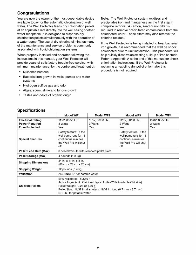
CongratulationsYou are now the owner of the most dependable device available today for the automatic chlorination of well water. The Well Protector feeds dry chlorination pellets at an adjustable rate directly into the well casing or other water receptacle. It is designed to dispense dry chlorination pellets simultaneously with the operation of a water pump. The use of dry chlorine eliminates many of the maintenance and service problems commonly associated with liquid chlorination systems.
When properly installed and operated following the instructions in this manual, your Well Protector will provide years of satisfactory trouble-free service, with minimum maintenance, for the control and treatment of:
• Nuisance bacteria
• Bacterial iron growth in wells, pumps and water systems
• Hydrogen sulfide gas and odor
• Algae, scum, slime and fungus growth
• Tastes and odors of organic origin
Note: The Well Protector system oxidizes and precipitates iron and manganese as the first step in complete removal. A carbon, sand or iron filter is required to remove precipitated contaminants from the chlorinated water. These filters may also remove the chlorine residual.
If the Well Protector is being installed to treat bacterial iron growth, it is recommended that the well be shock chlorinated prior to unit installation. This procedure will help quickly dissolve an existing buildup of iron bacteria. Refer to Appendix A at the end of this manual for shock chlorination instructions. If the Well Protector is replacing an existing dry pellet chlorinator this procedure is not required.
SpecificationsModel WP1 Model WP2 Model WP3 Model WP4
Electrical Rating Power Required Fuse Protected
115V, 60/50 Hz3 WattsYes
115V, 60/50 Hz3 WattsYes
220V, 60/50 Hz2 WattsYes
220V, 60/50 Hz2 WattsYes
Special Features
Safety feature: If the well pump runs for 15 continuous minutes the Well Pro will shut off.
Safety feature: If the well pump runs for 15 continuous minutes the Well Pro will shut off.
Pellet Feed Rate (Max) 3 pellets/minute with standard pellet plate
Pellet Storage (Max) 4 pounds (1.8 kg)
Shipping Dimensions34 in. x 11 in. x 8 in.(86 cm x 28 cm x 20 cm)
Shipping Weight 12 pounds (5.4 kg)
Validation ANSI/NSF 61 for potable water
Chlorine Pellets
EPA registered: 50510-1Active Ingredient: Calcium Hypochlorite (70% Available Chlorine)Pellet Weight: 0.28 oz (.79 g)Pellet Size: 11/32 in. diameter x 11/32 in. long (8.7 mm x 8.7 mm)NSF-60 for potable water

3
Installation
Mounting the Chlorinator (Refer to Figure 1)
Installing the casing mount to the well.
1. Attach the chains (Item 1) to the casing mount bracket (Item 2) using 5/16 - 18 x 3/4" long cap screws (Item 3), 5/16 - 18 nuts (Item 4) and 5/16 flat washer (Item 5).
2. Attach the J-bolt (Item 6) to the casing mount bracket (Item 2) using 5/16 - 18 nuts (Item 4) and 5/16” flat washers (Item 5).
3. Position the casing mounting bracket 1/2" below the bottom of the well cap and attach the chains (Item 1) to the J-bolt (Item 6). Tighten the 5/16 - 18 nuts (Item 4) until the casing mounting bracket is rigid enough to resist movement due to wind, accidental bumps and servicing.
Installing the Well Protector to the casing mount.
1. Attach the U-bolts (Item 7) and U-bolt straps (Item 10) to the casing mounting bracket (Item 2) with the 5/16-inch washers (Item 8) and the 5/16 - 18 nuts (Item 4).
2. Slide the Well Protector support tube (Item 9) thru the U-bolts (Item 7) and hand tighten. The Well Protector support tube may be shortened if necessary.
Figure 1
Well Venting and Pellet Discharge Tube Installation Instructions
Important:Water well construction and well components will vary, influencing proper installation of the Well Protector. Some of the most common installation considerations are described below. Refer to Appendix B for additional installation techniques. If you have any questions regarding proper installation of the Well Protector contact your dealer or Pentair Water Glendale Operations for consultation.
The chlorinator pellets must fall freely from the chlorinator into the water in the well casing without interference from pitless adapters, cable guards, torque stops, excess electrical wire or related pump fittings. Chlorine pellets in contact with metal parts will cause severe corrosion.
Important:The well must be vented.
For the Well Protector to function, the well must be vented to prevent moist air from the well being forced up into the chlorinator pellet container, causing the pellets to soften and jam the pellet plate.
For Wells With Sealed or Unsealed Caps and Pitless Adapters
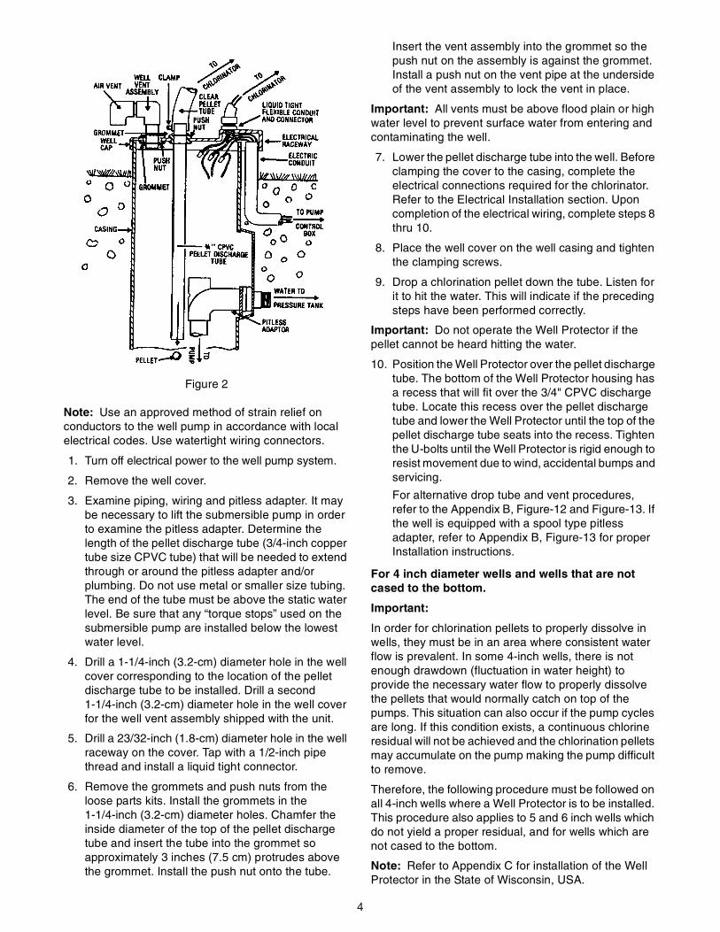
Figure 2 illustrates a typical non-sealed well casing and the modifications required to ensure that a pitless adapter does not prevent the pellets from dropping into the water, and that adequate well venting is provided.
4
Figure 2
Note: Use an approved method of strain relief on conductors to the well pump in accordance with local electrical codes. Use watertight wiring connectors.
1. Turn off electrical power to the well pump system.
2. Remove the well cover.
3. Examine piping, wiring and pitless adapter. It may be necessary to lift the submersible pump in order to examine the pitless adapter. Determine the length of the pellet discharge tube (3/4-inch copper tube size CPVC tube) that will be needed to extend through or around the pitless adapter and/or plumbing. Do not use metal or smaller size tubing. The end of the tube must be above the static water level. Be sure that any “torque stops” used on the submersible pump are installed below the lowest water level.
4. Drill a 1-1/4-inch (3.2-cm) diameter hole in the well cover corresponding to the location of the pellet discharge tube to be installed. Drill a second 1-1/4-inch (3.2-cm) diameter hole in the well cover for the well vent assembly shipped with the unit.
5. Drill a 23/32-inch (1.8-cm) diameter hole in the well raceway on the cover. Tap with a 1/2-inch pipe thread and install a liquid tight connector.
6. Remove the grommets and push nuts from the loose parts kits. Install the grommets in the 1-1/4-inch (3.2-cm) diameter holes. Chamfer the inside diameter of the top of the pellet discharge tube and insert the tube into the grommet so approximately 3 inches (7.5 cm) protrudes above the grommet. Install the push nut onto the tube.
Insert the vent assembly into the grommet so the push nut on the assembly is against the grommet. Install a push nut on the vent pipe at the underside of the vent assembly to lock the vent in place.
Important: All vents must be above flood plain or high water level to prevent surface water from entering and contaminating the well.
7. Lower the pellet discharge tube into the well. Before clamping the cover to the casing, complete the electrical connections required for the chlorinator. Refer to the Electrical Installation section. Upon completion of the electrical wiring, complete steps 8 thru 10.
8. Place the well cover on the well casing and tighten the clamping screws.
9. Drop a chlorination pellet down the tube. Listen for it to hit the water. This will indicate if the preceding steps have been performed correctly.
Important: Do not operate the Well Protector if the pellet cannot be heard hitting the water.
10. Position the Well Protector over the pellet discharge tube. The bottom of the Well Protector housing has a recess that will fit over the 3/4" CPVC discharge tube. Locate this recess over the pellet discharge tube and lower the Well Protector until the top of the pellet discharge tube seats into the recess. Tighten the U-bolts until the Well Protector is rigid enough to resist movement due to wind, accidental bumps and servicing.
For alternative drop tube and vent procedures, refer to the Appendix B, Figure-12 and Figure-13. If the well is equipped with a spool type pitless adapter, refer to Appendix B, Figure-13 for proper Installation instructions.
For 4 inch diameter wells and wells that are not cased to the bottom.
Important:
In order for chlorination pellets to properly dissolve in wells, they must be in an area where consistent water flow is prevalent. In some 4-inch wells, there is not enough drawdown (fluctuation in water height) to provide the necessary water flow to properly dissolve the pellets that would normally catch on top of the pumps. This situation can also occur if the pump cycles are long. If this condition exists, a continuous chlorine residual will not be achieved and the chlorination pellets may accumulate on the pump making the pump difficult to remove.
Therefore, the following procedure must be followed on all 4-inch wells where a Well Protector is to be installed. This procedure also applies to 5 and 6 inch wells which do not yield a proper residual, and for wells which are not cased to the bottom.
Note: Refer to Appendix C for installation of the Well Protector in the State of Wisconsin, USA.
5
Note: Pellet Drop Tube Installation - CPVC pellet drop tube material must conform to ASTM standards D2846 or F441 or F442 or F443 and be suitable for use with potable water.
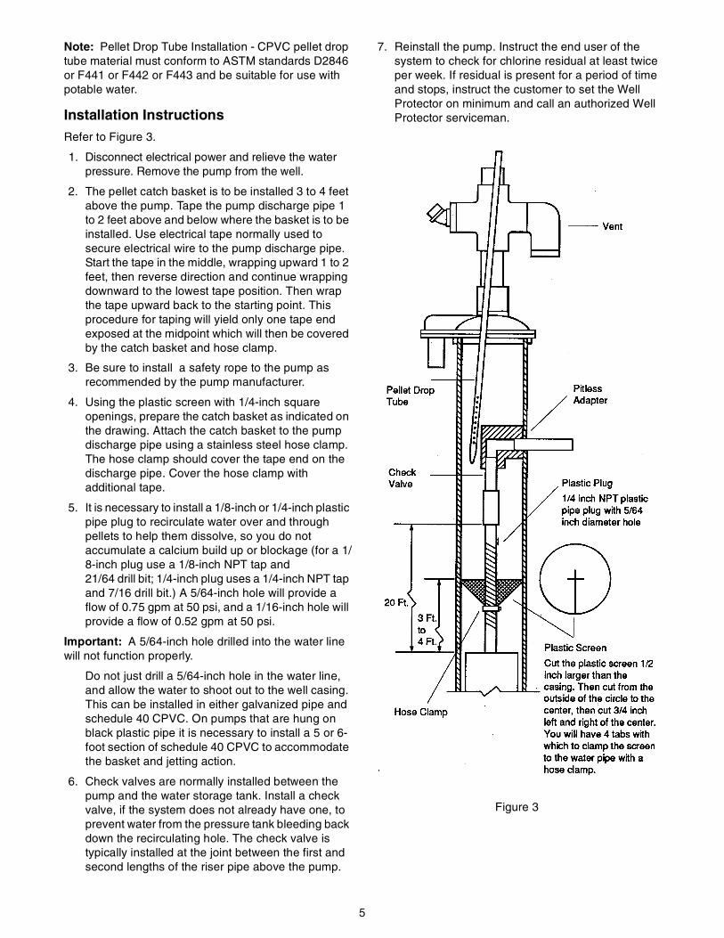
Installation InstructionsRefer to Figure 3.
1. Disconnect electrical power and relieve the water pressure. Remove the pump from the well.
2. The pellet catch basket is to be installed 3 to 4 feet above the pump. Tape the pump discharge pipe 1 to 2 feet above and below where the basket is to be installed. Use electrical tape normally used to secure electrical wire to the pump discharge pipe. Start the tape in the middle, wrapping upward 1 to 2 feet, then reverse direction and continue wrapping downward to the lowest tape position. Then wrap the tape upward back to the starting point. This procedure for taping will yield only one tape end exposed at the midpoint which will then be covered by the catch basket and hose clamp.
3. Be sure to install a safety rope to the pump as recommended by the pump manufacturer.
4. Using the plastic screen with 1/4-inch square openings, prepare the catch basket as indicated on the drawing. Attach the catch basket to the pump discharge pipe using a stainless steel hose clamp. The hose clamp should cover the tape end on the discharge pipe. Cover the hose clamp with additional tape.
5. It is necessary to install a 1/8-inch or 1/4-inch plastic pipe plug to recirculate water over and through pellets to help them dissolve, so you do not accumulate a calcium build up or blockage (for a 1/8-inch plug use a 1/8-inch NPT tap and 21/64 drill bit; 1/4-inch plug uses a 1/4-inch NPT tap and 7/16 drill bit.) A 5/64-inch hole will provide a flow of 0.75 gpm at 50 psi, and a 1/16-inch hole will provide a flow of 0.52 gpm at 50 psi.
Important: A 5/64-inch hole drilled into the water line will not function properly.
Do not just drill a 5/64-inch hole in the water line, and allow the water to shoot out to the well casing. This can be installed in either galvanized pipe and schedule 40 CPVC. On pumps that are hung on black plastic pipe it is necessary to install a 5 or 6-foot section of schedule 40 CPVC to accommodate the basket and jetting action.
6. Check valves are normally installed between the pump and the water storage tank. Install a check valve, if the system does not already have one, to prevent water from the pressure tank bleeding back down the recirculating hole. The check valve is typically installed at the joint between the first and second lengths of the riser pipe above the pump.
7. Reinstall the pump. Instruct the end user of the system to check for chlorine residual at least twice per week. If residual is present for a period of time and stops, instruct the customer to set the Well Protector on minimum and call an authorized Well Protector serviceman.
Figure 3
6
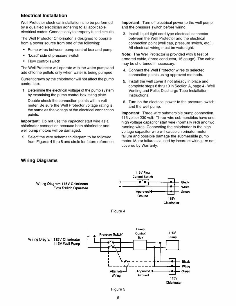
Electrical InstallationWell Protector electrical installation is to be performed by a qualified electrician adhering to all applicable electrical codes. Connect only to properly fused circuits.
The Well Protector Chlorinator is designed to operate from a power source from one of the following:
• Pump wires between pump control box and pump
• “Load” side of pressure switch
• Flow control switch
The Well Protector will operate with the water pump and add chlorine pellets only when water is being pumped.
Current drawn by the chlorinator will not affect the pump control box.
1. Determine the electrical voltage of the pump system by examining the pump control box rating plate.
Double check the connection points with a volt meter. Be sure the Well Protector voltage rating is the same as the voltage at the electrical connection points.
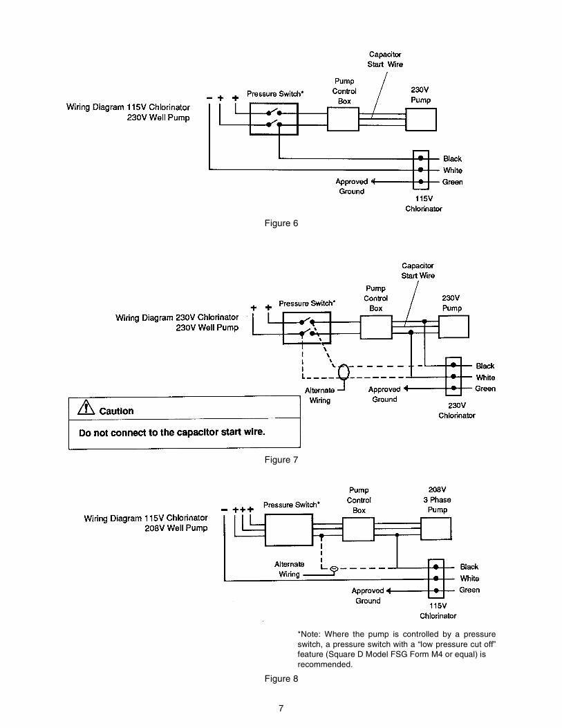
Important: Do not use the capacitor start wire as a chlorinator connection because both chlorinator and well pump motors will be damaged.
2. Select the wire schematic diagram to be followed from Figures 4 thru 8 and circle for future reference.
Important: Turn off electrical power to the well pump and the pressure switch before wiring.
3. Install liquid tight cord type electrical connector between the Well Protector and the electrical connection point (well cap, pressure switch, etc.). All electrical wiring must be watertight.
Note: The Well Protector is provided with 6 feet of armored cable, (three conductor, 16 gauge). The cable may be shortened if necessary.
4. Connect the Well Protector wires to selected connection points using approved methods.
5. Install the well cover if not already in place and complete steps 8 thru 10 in Section A, page 4 - Well Venting and Pellet Discharge Tube Installation Instructions.
6. Turn on the electrical power to the pressure switch and the well pump.
Important: Three-wire submersible pump connection, 115 volt or 230 volt: Three-wire submersibles have one high voltage capacitor start wire (normally red) and two running wires. Connecting the chlorinator to the high voltage capacitor wire will cause chlorinator motor failure and possible damage the submersible pump motor. Motor failures caused by incorrect wiring are not covered by Warranty.
Wiring Diagrams
Figure 4
Figure 5
7
Figure 6
Figure 7
Figure 8
*Note: Where the pump is controlled by a pressureswitch, a pressure switch with a “low pressure cut off”feature (Square D Model FSG Form M4 or equal) is recommended.

8
System Checkout
Before adding pellets, run water until the well pump runs. The Well Protector pellet plate (Figure 9) should rotate with a stop and start motion while the water pump runs.
Figure 9
SizingThe chlorine feed rate required will vary based on two factors:
1. The “chlorine demand” of the well water.
2. The flow rate at which water is pumped from the well.
Estimating the chlorine demand:
The guide on page 12 can be used to estimate the chlorine demand of the water supply. Be aware that this is only a means to estimate usage and will vary depending on your particular application. Add chlorine residual to demand to arrive at total chlorine dosage.
1. Use guide to estimate the dosage rate for the condition you wish to treat.
Note: Feeding 2 ppm of chlorine for each part of H2S will provide taste and odor control. It will take at least 8.4 ppm of chlorine before a residual will be detectable.
Sulfate reducing bacteria can cause H2S in a water supply. Eliminating the bacteria will eliminate the H2S odor and direct treatment of H2S will not be necessary.
High quantities of chlorine are required to react with and eliminate growth of slime in the well caused by bacterial
iron. Once removed, much lower settings can be used to keep the bacteria from re-establishing itself in the water system.
2. Once the required chlorine dosage rate has been estimated, use the Pellet Drop Rate Chart to estimate the total chlorine usage and the setting for the pellet drop rate.
Note: The chlorinator must be adjusted to deliver between 0.4 and 0.8 ppm of chlorine for water for human consumption and up to 3 ppm for livestock water system protection.
The actual setting will need to be adjusted slightly to account for various pumping rates.
The pellet drop rate chart is based on 6-hole pellet plate. In cases where lower chlorine dosages are required to satisfy demand of your installation, a 2-hole pellet plate is available as an option to provide a chlorine dosage 1/3 times that which is indicated in the pellet drop rate chart.
OperationThe Well Protector controls are located on the power module inside the unit for weather protection.
Pellet Feed Index Screw
The Pellet Feed Index Screw adjusts pellet feed rate.
Figure 10
Fuse
All models are fused to prevent damage to the Well Protector if accidentally miswired.
To check the fuse, remove the pellet container and power module from the Well Protector housing. Hold the pellet container upright (so that printing is readable). The fuse is housed in a drawer in the electrical connector. Pull up on the drawer to expose the fuse. The fuse in the lower position is the fuse in use and the fuse in the upper position is a spare. Replace the fuse if necessary. Return the fuse drawer to its original position. Invert the pellet container and approximately align the pellet drop tube with the drop tube in the bottom of the lower housing.
A slight rotating of the power module assembly may be necessary to properly align the pellet drop tube and electrical connector with the mating parts in the lower housing.
9
To add pellets, remove the Well Protector pellet container and power module from the Well Protector housing. To remove the power module, firmly grasp the pellet container and lift the power module assembly straight up until the pellet drop tube clears the lower housing) and unscrew the power module. Remove the power module from the pellet container. Unscrew the child resistant cap on the new pellet container. If any pellets are left in the old pellet container pour them into the new pellet container. Place the power module on top of the new pellet container and tighten.
Important: Do not over tighten pellet container and power module.
Invert the pellet container and approximately align the pellet drop tube with the drop tube in the bottom of the lower housing. A slight rotating of the power module assembly may be necessary to properly align the pellet drop tube and electrical connector with the mating parts in the lower housing.
Note: It is important to keep the Well Protector pellet container cover and pellet shipping container cover
tightly closed. Chlorine absorbs moisture from the air. Damp pellets are not suitable for use in the Well Protector. The limited warranty will not cover damage due to moisture-softened pellets used in the Well Protector.
Important: To prevent children and unauthorized persons from opening the pellet container, a padlock must be installed.
Use the pellet feed index screw (Figure-9), to make adjustments for individual wells. Start systems at the middle setting. Once each day, check water for proper Chlorine residual with the test kit provided. To decrease chlorine content, turn pellet feed index screw counterclockwise. To increase chlorine content, turn pellet feed index screw clockwise.
Unchlorinated water may carry bacteria. Check the chlorine content of the well water every day and adjust the feed rate accordingly.
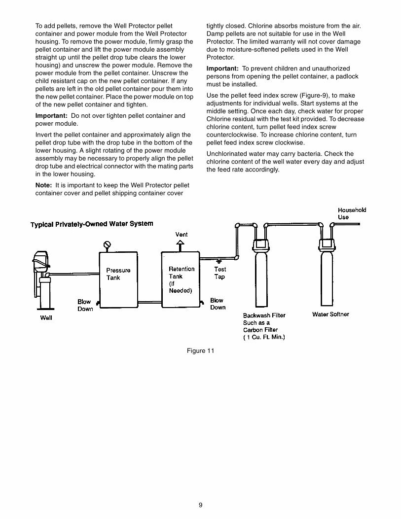
Figure 11
10
Plumbing Requirements
Contact Time
For effective bacteria kill and iron precipitation, prescribed levels of chlorine must be in contact with the water for 20 minutes. By adding chlorine to the well, the Well Protector Dry Pellet Chlorinator has the added benefit of using the well casing, pump and riser, and lateral pipes for added retention time. If the water demand requires nearly continuous running of the pump, a properly sized retention tank must be installed to assure proper retention time. Figure-11 shows proper location of retention tank in system.
Carbon Filters
To provide effective filtration of precipitated iron, manganese and excess chlorine, install a carbon filter in the household water supply line (Figure-11). Chlorine-free drinking water can be obtained by installing point-of-use carbon filters.
Important: Carbon filters remove all chlorine taste and odor. To ensure that the chlorinator system is functioning properly and that proper protection is being maintained, a daily chlorine test must be taken ahead of the carbon filter.
MaintenanceThe Well Protector does not require a regular maintenance routine. However, after long periods of operation, there may be a build up of chlorine dust in the dropping mechanism.
To clean the pellet delivery mechanism, follow these instructions:
1. Remove the power module assembly and unscrew the pellet container.
2. Using a flat blade screwdriver, pry the pellet dam (refer to page 14, item 11) up off the pellet plate (page 14, item 12).
3. Thread a 6-32 machine screw into the brass insert in the center of the pellet plate and pull up on the screw to remove the plate. When the pellet plate is removed, the U-cup seal (page 14, item 13) should be in place around the shaft of the pellet plate.
4. Clean the power module mechanism, the pellet plate and pellet dam with a clean damp cloth. Allow all parts to dry completely before reassembly.
To reassemble the mechanism:
1. Check that the u-cup seal is in position on the stem of the pellet plate, with the lips of the seal facing UP.
2. Align the flats in the stem of the pellet plate with the flats of the drive shaft, and slide the pellet plate into position.
3. Align the flat on the bottom of the pellet dam with the flat in the power module.
4. Press the pellet dam into position.
5. Replace the pellet container and the unit is ready for operation.
Operation RequirementsYour Well Protector Dry Pellet Chlorinator is the most reliable chlorination system available today. However, to realize the continued benefits of chlorinated water, the following procedures must be followed by the owner.
Test water daily for chlorine residual using the test kit provided. Adjust chlorinator feed rate to maintain the residual at 0.4 to 0.8 ppm.
Maintain a supply of chlorination pellets. The Well Protector must be kept supplied with pellets meeting the specifications required for this machine. Use only Pentair Water dry chlorination pellets available from your Well Protector dealer.
Important: Work safely. Chlorine is a strong oxidizer and requires careful handling. Handle chlorination pellets as instructed in this manual. Read the label on the pellet container. Keep children away from chlorinator and the stored pellets.
Keep pellets dry. The chlorinator pellet container must be kept tightly closed, to prevent moisture absorption. Chlorinator damage due to damp pellets is not covered by the limited warranty.
Important: The pellet drop tube on the bottom of the power module may need occasional lubrication to ease insertion into the lower housing. Use only Halocarbon Chlorotrifluoroethylene 25-5S grease to lubricate the tube and the O-ring. Use of any other lubricant could result in a dangerous chemical reaction.
Securely replace cover on opened chlorine pellet container. Well Protector chlorination pellets are shipped in containers designed to be child resistant and air tight.

11
Chlorination Treatment For: Typical Chlorine Dosage Rates:
Algae 3-5 ppm chlorine
Bacteria 3-5 chlorine
Hydrogen Sulfide:Taste and odor controlDestruction
2 times H2S content = ppm chlorine (1)8.4 times H2S content = ppm chlorine (1)
Iron bacteria 1-10 ppm chlorine (2)
Iron precipitation 6.4 times Fe+3 content - ppm chlorine
Manganese precipitation 1.3 times Mn content = pm chlorine
Odor 1-3 ppm chlorine
Pellet Drop Rate Chart
Estimated Chlorine UsageChlorine Dosage Rate PPM
Pellet Drop Rate Setting(Approximate)Gallons Water Treated
per Lb. of PelletsGallons Water Treated
Per/Pellet
28,000 49 3
14,000 25 6
9,333 16 9
7,000 12 12
5,600 10 15
4,666 8 18
4,000 7 21
3,500 6 24
3,100 5.4 27
2,860 5 30
2,333 4 36
1,766 3 48
1,566 2.7 54
1,400 2.5 60
1,133 2 75
923 1.6 90
700 1.2 120
566 1 150
366 .7 225
12
Safety Instructions
Storage and Disposal
Keep this product DRY, in a tightly closed container when not in use. Store in a cool, dry, well-ventilated area, away from heat or open flame.
In case of decomposition, isolate the container (if possible) and flood area with large amounts of water to dissolve all materials before discarding container.
DO NOT REUSE THE EMPTY CONTAINER, BUT PLACE IN TRASH COLLECTION. Do not contaminate food or feed by storage, disposal, or cleaning of equipment.
Triple rinse (or equivalent). Then offer for recycling or reconditioning, or puncture and dispose of in a sanitary landfill, or incineration, or if allowed by state and local authorities, by burning. If this container is burned, stay away from the smoke.
Pesticide wastes are acutely hazardous. Improper disposal of excess pesticides, spray mixture, or rinsate is a violation of Federal Law. If these wastes cannot be disposed of by use according to label instructions, contact your State Pesticide or Environmental Control Agency, or Hazardous Waste representative at the nearest EPA regional office for information or guidance.
Important: Do not mix the chlorine pellets with any other chemical and do not add pellets to any other container which may have contained other chemicals, as a violent reaction may occur.
Caution in Handling Chlorine:
• Chlorine is a strong oxidant.
• Keep pellet containers tightly closed and child resistant locking devices in place.
• May cause eye damage. Do not get in eyes.
• May produce chemical burns. Avoid contact with skin and clothing.
• May be harmful or fatal if swallowed. Keep pellets out of each of children.
• Always rinse empty container with water, then destroy.
• Store pellets in cool, dry place, away from heat, sparks and flame.
• Always keep pellets clean and free from any dirt, grease, or other foreign materials.
• Always use a clean plastic container or scoop to handle pellets. Never bare hands or cloth gloves. Clean rubber gloves may be used. Never inhale dust or fumes when handling chlorine pellets.
Antidotes:
External - Wash with water at least 15 minutes.
For eyes - Get prompt medical attention.
Internal - Drink large quantities of milk, water or egg whites. Call a physician immediately!
Important: Changing water conditions by adding chlorine or removing iron bacteria, hydrogen sulfide, softening, etc. will change the taste of the water. Animals and birds may reduce their normal water consumption until they become accustomed to the new taste of the water. To minimize this effect, start feeding chlorine at a very low rate and increase to the levels over several weeks time.
Chlorine Identification:
Calcium Hypochlorite Mixture#UN1479 EPA No. 50510-1.
Pentair Water reserves the right to make improvements on this product which might not be reflected in this owners manual.
13
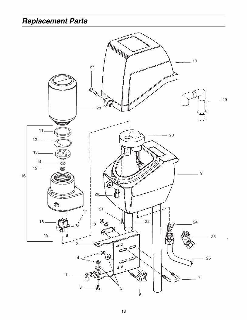
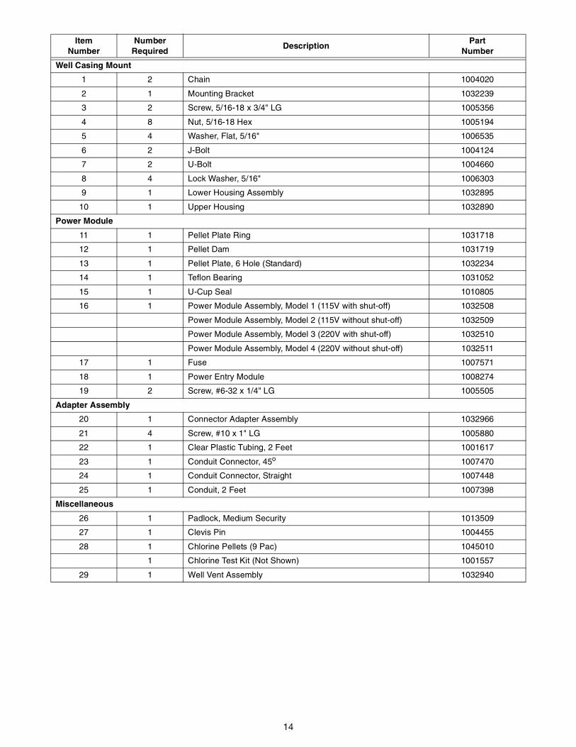
Replacement Parts
1
2
3
4
5
6
7
8
9
10
12
13
14
11
15
16
17
18
19
20
21
22
23
24
25
26
27
28
29
14
ItemNumber
NumberRequired
DescriptionPart
Number
Well Casing Mount
1 2 Chain 1004020
2 1 Mounting Bracket 1032239
3 2 Screw, 5/16-18 x 3/4" LG 1005356
4 8 Nut, 5/16-18 Hex 1005194
5 4 Washer, Flat, 5/16" 1006535
6 2 J-Bolt 1004124
7 2 U-Bolt 1004660
8 4 Lock Washer, 5/16" 1006303
9 1 Lower Housing Assembly 1032895
10 1 Upper Housing 1032890
Power Module
11 1 Pellet Plate Ring 1031718
12 1 Pellet Dam 1031719
13 1 Pellet Plate, 6 Hole (Standard) 1032234
14 1 Teflon Bearing 1031052
15 1 U-Cup Seal 1010805
16 1 Power Module Assembly, Model 1 (115V with shut-off) 1032508
Power Module Assembly, Model 2 (115V without shut-off) 1032509
Power Module Assembly, Model 3 (220V with shut-off) 1032510
Power Module Assembly, Model 4 (220V without shut-off) 1032511
17 1 Fuse 1007571
18 1 Power Entry Module 1008274
19 2 Screw, #6-32 x 1/4" LG 1005505
Adapter Assembly
20 1 Connector Adapter Assembly 1032966
21 4 Screw, #10 x 1" LG 1005880
22 1 Clear Plastic Tubing, 2 Feet 1001617
23 1 Conduit Connector, 45o 1007470
24 1 Conduit Connector, Straight 1007448
25 1 Conduit, 2 Feet 1007398
Miscellaneous
26 1 Padlock, Medium Security 1013509
27 1 Clevis Pin 1004455
28 1 Chlorine Pellets (9 Pac) 1045010
1 Chlorine Test Kit (Not Shown) 1001557
29 1 Well Vent Assembly 1032940
15
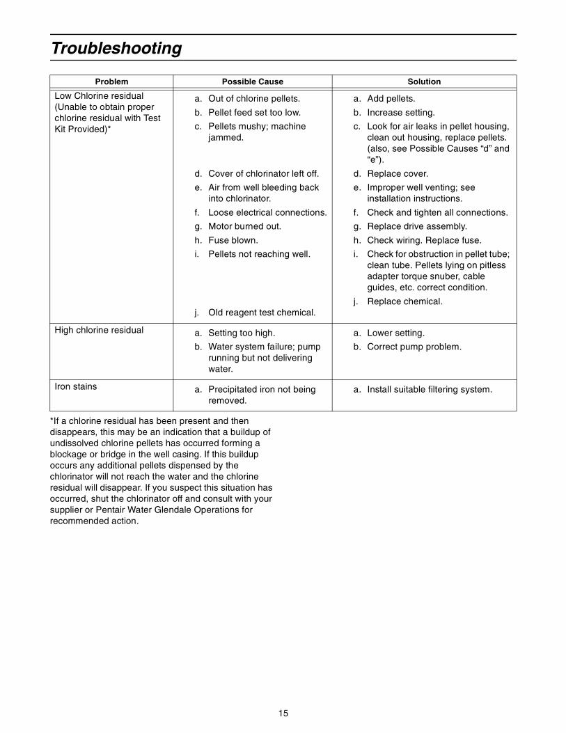
Troubleshooting
*If a chlorine residual has been present and then disappears, this may be an indication that a buildup of undissolved chlorine pellets has occurred forming a blockage or bridge in the well casing. If this buildup occurs any additional pellets dispensed by the chlorinator will not reach the water and the chlorine residual will disappear. If you suspect this situation has occurred, shut the chlorinator off and consult with your supplier or Pentair Water Glendale Operations for recommended action.
Problem Possible Cause Solution
Low Chlorine residual (Unable to obtain proper chlorine residual with Test Kit Provided)*
a. Out of chlorine pellets.
b. Pellet feed set too low.
c. Pellets mushy; machine jammed.
d. Cover of chlorinator left off.
e. Air from well bleeding back into chlorinator.
f. Loose electrical connections.
g. Motor burned out.
h. Fuse blown.
i. Pellets not reaching well.
j. Old reagent test chemical.
a. Add pellets.
b. Increase setting.
c. Look for air leaks in pellet housing, clean out housing, replace pellets. (also, see Possible Causes “d” and “e”).
d. Replace cover.
e. Improper well venting; see installation instructions.
f. Check and tighten all connections.
g. Replace drive assembly.
h. Check wiring. Replace fuse.
i. Check for obstruction in pellet tube; clean tube. Pellets lying on pitless adapter torque snuber, cable guides, etc. correct condition.
j. Replace chemical.
High chlorine residual a. Setting too high.
b. Water system failure; pump running but not delivering water.
a. Lower setting.
b. Correct pump problem.
Iron stains a. Precipitated iron not being removed.
a. Install suitable filtering system.
16
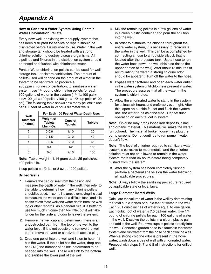
Appendix A
How to Sanitize a Water System Using Pentair Water Chlorination Pellets
Every new well, or existing water supply system that has been disrupted for service or repair, should be disinfected before it is returned to use. Water in the well and storage tank should be treated with a strong chlorine solution to destroy disease organisms. All pipelines and fixtures in the distribution system should be rinsed and flushed with chlorinated water.
Pentair Water chlorination pellets can be used for well, storage tank, or cistern sanitization. The amount of pellets used will depend on the amount of water in the system to be sanitized. To produce a 200 ppm chlorine concentration, to sanitize a water system, use 1/4 pound chlorination pellets for each 100 gallons of water in the system (1/4 lb/100 gal = 4 oz/100 gal = 100 pellets/100 gal = 1/2 cup pellets/100 gal). The following table shows how many pellets to use per 100 feet of water in various diameter wells.
Note: Tablet weight - 1.14 gram each, 25 pellets/oz., 400 pellets lb.
1 cup pellets = 1/2 lb., or 8 oz., or 200 pellets.
Drilled Wells
1. Remove the cap or seal from the casing and measure the depth of water in the well, then refer to the table to determine how many chlorine pellets should be used. In some instances removing the seal to measure the water can be a difficult task, and it is easier to estimate well and water depth from the well log or other records. As a general rule, it is better to use too much chlorine than too little, but it will take longer for the taste and odor to leave the system.
2. Remove the well cap and determine if there is an unobstructed path from the top of the well to the water level, if it is not possible to remove the well cap, remove the vent or sanitization access plug.
3. Drop one pellet into the well and listen to hear if it hits the water. If the pellet hits the water, drop one-half (1/2) the number of pellets determined to be needed into the well. These will sink to the bottom and sanitize the lower part of the well.
4. Mix the remaining pellets in a few gallons of water in a clean plastic container and pour the solution into the well.
5. In order to distribute the chlorine throughout the entire water system, it is necessary to recirculate the water in the well. This can be accomplished by connecting a hose to an outside silcock that is located after the pressure tank. Use a hose to run the water back down the well (this also rinses the upper portion of the well). After about 15 minutes of recirculating the water, a strong chlorine odor should be apparent. Turn off the water to the hose.
6. Bypass water softener and open each water outlet in the water system until chlorine is present in water. The procedure assures that all the water in the system is chlorinated.
7. Allow the chlorinated water to stand in the system for at least six hours, and preferably overnight. After this, open an outside faucet and flush the system until the water runs chlorine-free. Repeat flush operation on each faucet in system.
Note: Chlorine may break loose iron deposits, slime and organic material. This material will make the water run colored. The material broken loose may plug the pump screens. Do not continue to run pump if water doesn’t flow.
Note: The level of chlorine required to sanitize a water system is corrosive to most metals, and the chlorine solution must not be allowed to remain in the water system more than 36 hours before being completely flushed from the system.
8. After the system has been completely flushed, perform a bacterial analysis on the water following all applicable procedures.
Note: Always follow the sanitizing procedure required by applicable state or local laws.
Large Diameter Bored Wells
Calculate the volume of water in the well by determining the total cubic inches or cubic feet of water in the well. Each 231 cubic inches of water is equal to one gallon. Each cubic foot of water is 7.5 gallons water. Use 1/4 pound of chlorine pellets for each 100 gallons of water in the well. Dissolve the pellets in a clean, plastic pail and add to the well. Pour two cups of pellets directly into the well. Connect a garden hose to a faucet in the water system and run water from the hose back down the well. When a strong chlorine odor is present in the hose water, wash down sides of well with chlorinated water. Proceed with steps 6, 7 and 8 of instructions for drilled wells.
Well Diameter(inches)
For Each 100 Feet of Water Depth Use:
Weight of Tablets
Lbs. - Oz.
Cups of Tablets
Tablets
2 0-0.6 1/10 20
3 0-1.5 2/10 40
4 0-2.6 3/10 65
5 0-4 1/2 100
6 0-6 7/10 150
17
Springs and Cisterns
Mix about 1/2 cup of pellets in 5 gallons of water and use this to scrub the walls of the spring box or holding tank. With a constant flow of fresh water from the spring, there is probably no way of detaining the chlorine solution in the reservoir for more than a few minutes. Cisterns can be disinfected in the same way but a source of clean water will be needed to flush the dirty waste out of the system.
Note: This product is intended to sanitize a water supply system that been temporarily contaminated, and is not intended to solve a recurring contamination problem.
18
Appendix B
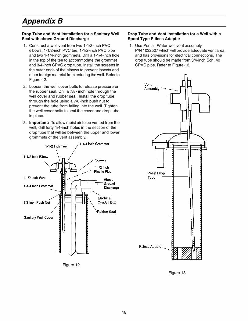
Drop Tube and Vent Installation for a Sanitary Well Seal with above Ground Discharge
1. Construct a well vent from two 1-1/2-inch PVC elbows, 1-1/2-inch PVC tee, 1-1/2-inch PVC pipe and two 1-1/4-inch grommets. Drill a 1-1/4-inch hole in the top of the tee to accommodate the grommet and 3/4-inch CPVC drop tube. Install the screens in the outer ends of the elbows to prevent insects and other foreign material from entering the well. Refer to Figure-12.
2. Loosen the well cover bolts to release pressure on the rubber seal. Drill a 7/8- inch hole through the well cover and rubber seal. Install the drop tube through the hole using a 7/8-inch push nut to prevent the tube from falling into the well. Tighten the well cover bolts to seal the cover and drop tube in place.
3. Important: To allow moist air to be vented from the well, drill forty 1/4-inch holes in the section of the drop tube that will be between the upper and lower grommets of the vent assembly.
Figure 12
Drop Tube and Vent Installation for a Well with a Spool Type Pitless Adapter
1. Use Pentair Water well vent assembly P/N 1032507 which will provide adequate vent area, and has provisions for electrical connections. The drop tube should be made from 3/4-inch Sch. 40 CPVC pipe. Refer to Figure-13.
Figure 13
19
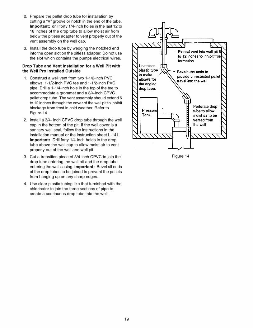
2. Prepare the pellet drop tube for installation by cutting a “V” groove or notch in the end of the tube. Important: drill forty 1/4-inch holes in the last 12 to 18 inches of the drop tube to allow moist air from below the pitless adapter to vent properly out of the vent assembly on the well cap.
3. Install the drop tube by wedging the notched end into the open slot on the pitless adapter. Do not use the slot which contains the pumps electrical wires.
Drop Tube and Vent Installation for a Well Pit with the Well Pro Installed Outside
1. Construct a well vent from two 1-1/2-inch PVC elbows. 1-1/2-inch PVC tee and 1-1/2-inch PVC pipe. Drill a 1-1/4-inch hole in the top of the tee to accommodate a grommet and a 3/4-inch CPVC pellet drop tube. The vent assembly should extend 6 to 12 inches through the cover of the well pit to inhibit blockage from frost in cold weather. Refer to Figure-14.
2. Install a 3/4- inch CPVC drop tube through the well cap in the bottom of the pit. If the well cover is a sanitary well seal, follow the instructions in the installation manual or the instruction sheet L-141. Important: Drill forty 1/4-inch holes in the drop tube above the well cap to allow moist air to vent properly out of the well and well pit.
3. Cut a transition piece of 3/4-inch CPVC to join the drop tube entering the well pit and the drop tube entering the well casing. Important: Bevel all ends of the drop tubes to be joined to prevent the pellets from hanging up on any sharp edges.
4. Use clear plastic tubing like that furnished with the chlorinator to join the three sections of pipe to create a continuous drop tube into the well.
Figure 14
20
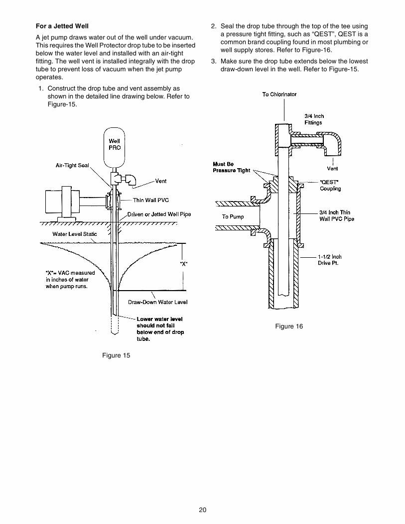
For a Jetted Well
A jet pump draws water out of the well under vacuum. This requires the Well Protector drop tube to be inserted below the water level and installed with an air-tight fitting. The well vent is installed integrally with the drop tube to prevent loss of vacuum when the jet pump operates.
1. Construct the drop tube and vent assembly as shown in the detailed line drawing below. Refer to Figure-15.
Figure 15
2. Seal the drop tube through the top of the tee using a pressure tight fitting, such as “QEST”, QEST is a common brand coupling found in most plumbing or well supply stores. Refer to Figure-16.
3. Make sure the drop tube extends below the lowest draw-down level in the well. Refer to Figure-15.
Figure 16
21
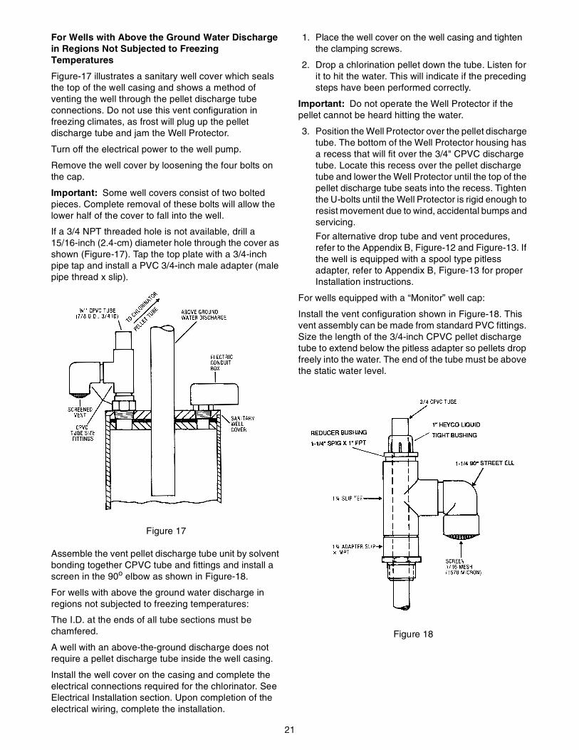
For Wells with Above the Ground Water Discharge in Regions Not Subjected to Freezing Temperatures
Figure-17 illustrates a sanitary well cover which seals the top of the well casing and shows a method of venting the well through the pellet discharge tube connections. Do not use this vent configuration in freezing climates, as frost will plug up the pellet discharge tube and jam the Well Protector.
Turn off the electrical power to the well pump.
Remove the well cover by loosening the four bolts on the cap.
Important: Some well covers consist of two bolted pieces. Complete removal of these bolts will allow the lower half of the cover to fall into the well.
If a 3/4 NPT threaded hole is not available, drill a 15/16-inch (2.4-cm) diameter hole through the cover as shown (Figure-17). Tap the top plate with a 3/4-inch pipe tap and install a PVC 3/4-inch male adapter (male pipe thread x slip).
Figure 17
Assemble the vent pellet discharge tube unit by solvent bonding together CPVC tube and fittings and install a screen in the 90o elbow as shown in Figure-18.
For wells with above the ground water discharge in regions not subjected to freezing temperatures:
The I.D. at the ends of all tube sections must be chamfered.
A well with an above-the-ground discharge does not require a pellet discharge tube inside the well casing.
Install the well cover on the casing and complete the electrical connections required for the chlorinator. See Electrical Installation section. Upon completion of the electrical wiring, complete the installation.
1. Place the well cover on the well casing and tighten the clamping screws.
2. Drop a chlorination pellet down the tube. Listen for it to hit the water. This will indicate if the preceding steps have been performed correctly.
Important: Do not operate the Well Protector if the pellet cannot be heard hitting the water.
3. Position the Well Protector over the pellet discharge tube. The bottom of the Well Protector housing has a recess that will fit over the 3/4" CPVC discharge tube. Locate this recess over the pellet discharge tube and lower the Well Protector until the top of the pellet discharge tube seats into the recess. Tighten the U-bolts until the Well Protector is rigid enough to resist movement due to wind, accidental bumps and servicing.
For alternative drop tube and vent procedures, refer to the Appendix B, Figure-12 and Figure-13. If the well is equipped with a spool type pitless adapter, refer to Appendix B, Figure-13 for proper Installation instructions.
For wells equipped with a “Monitor” well cap:
Install the vent configuration shown in Figure-18. This vent assembly can be made from standard PVC fittings. Size the length of the 3/4-inch CPVC pellet discharge tube to extend below the pitless adapter so pellets drop freely into the water. The end of the tube must be above the static water level.
Figure 18
22
Appendix C
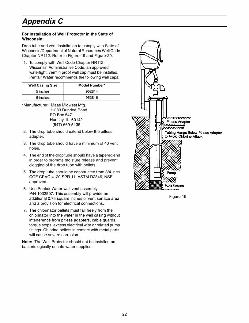
For Installation of Well Protector in the State of Wisconsin:
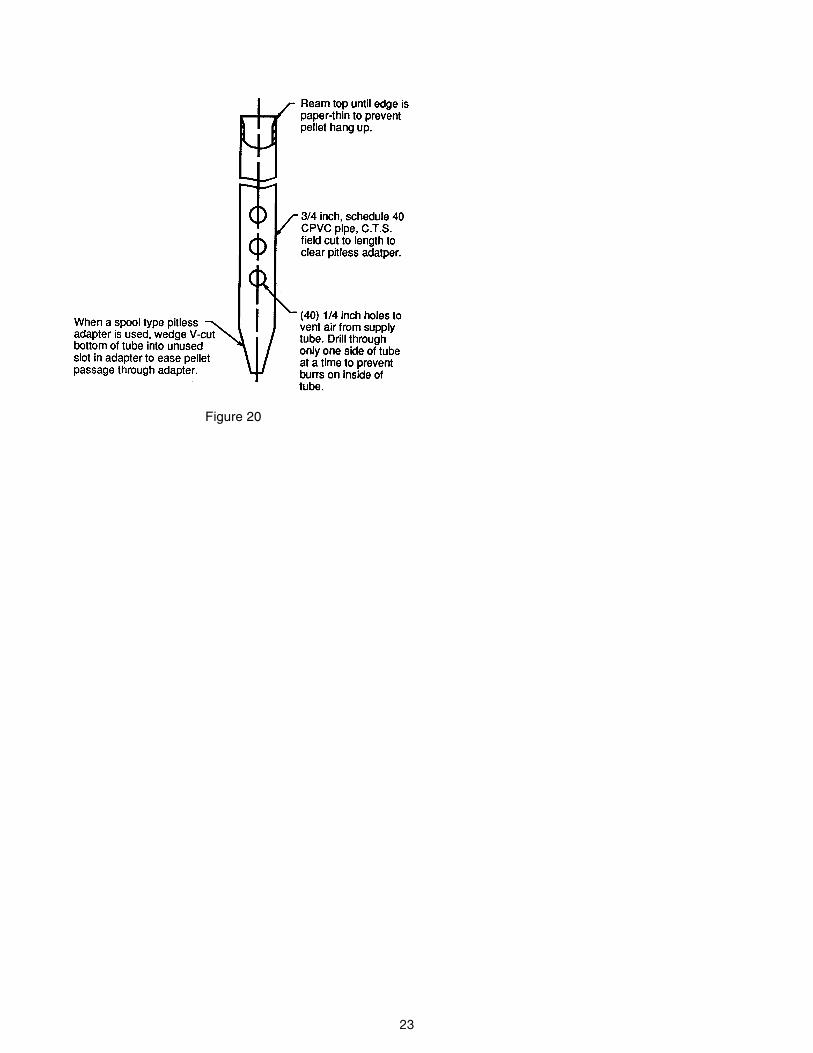
Drop tube and vent installation to comply with State of Wisconsin/Department of Natural Resources Well Code Chapter NR112. Refer to Figure-19 and Figure-20.
1. To comply with Well Code Chapter NR112, Wisconsin Administrative Code, an approved watertight, vermin proof well cap must be installed. Pentair Water recommends the following well caps:
*Manufacturer: Maas Midwest Mfg. 11283 Dundee RoadPO Box 547Huntley, IL 60142
(847) 669-5135
2. The drop tube should extend below the pitless adapter.
3. The drop tube should have a minimum of 40 vent holes.
4. The end of the drop tube should have a tapered end in order to promote moisture release and prevent clogging of the drop tube with pellets.
5. The drop tube should be constructed from 3/4-inch CGF CPVC 4120 SPR 11, ASTM D2846, NSF approved.
6. Use Pentair Water well vent assembly P/N 1032507. This assembly will provide an additional 0.75 square inches of vent surface area and a provision for electrical connections.
7. The chlorinator pellets must fall freely from the chlorinator into the water in the well casing without interference from pitless adapters, cable guards, torque stops, excess electrical wire or related pump fittings. Chlorine pellets in contact with metal parts will cause severe corrosion.
Note: The Well Protector should not be installed on bacteriologically unsafe water supplies.
Figure 19
Well Casing Size Model Number*
5 inches 952814
6 inches 952816
23
Figure 20

© 2008 Pentair Residential Filtration, LLCP/N 1017766 Rev E