wcap-16182-np-a, revision 3, westinghouse bwr control rod … · bwr control rod cr 99 licensing...
TRANSCRIPT
Westinghouse Non-Proprietary Class 3
WCAP-16182-NP-A November 2017 Revision 3
Westinghouse BWR Control Rod CR 99 Licensing Report – Update to Mechanical Design Limits
*** This record was final approved on 11/9/2017 3:13:35 AM. ( This statement was added by the PRIME system upon its validation)
Westinghouse Non-Proprietary Class 3
*Electronically approved records are authenticated in the electronic document management system.
Westinghouse Electric Company LLC 1000 Westinghouse Drive
Cranberry Township, PA 16066, USA
© 2017 Westinghouse Electric Company LLC All Rights Reserved
WCAP-16182-NP-A Revision 3
Westinghouse BWR Control Rod CR 99 Licensing Report – Update to Mechanical Design Limits
Magnus Jinnestrand Flow Design, Loads and Structural Verification
Björn Rebensdorff
Nuclear Fuel, Global Product Management
November 2017
Technical Reviewer: Anghel Enica, Core Engineering *
Licensing Reviewer: Bradley F. Maurer, Product Licensing *
Approved: Sven E. Perzon, Manager * Flow Design, Loads and Structural Verification
Edmond J. Mercier, Manager * Product Licensing
*** This record was final approved on 11/9/2017 3:13:35 AM. ( This statement was added by the PRIME system upon its validation)
Westinghouse Non-Proprietary Class 3 ii
WCAP-16182-NP-A November 2017 Revision 3
TABLE OF CONTENTS
Section Description
A Final Safety Evaluation
Letter from Dennis C. Morey (NRC) to J. A. Gresham (Westinghouse) , “Final Safety Evaluation for Westinghouse Electric Company (Westinghouse) Topical Report WCAP-16182-P/NP, Revision 3, “Westinghouse BWR Control Rod CR 99 Licensing Report – Update To Mechanical Design Limits” (TAC No. ME2630), with attachment “NRC Resolution Of Comments On Draft Safety Evaluation For Topical Report Safety Evaluation WCAP-16182-P/NP, Revision 3, “Westinghouse BWR Control Rod CR 99 Licensing Report – Update To Mechanical Design Limits” Westinghouse Electric Company. Project No. 700,” August 17, 2017.
B Submittal of Topical Report
Westinghouse Letter LTR-NRC-07-59, Revision 1, April 9, 2008, “Submittal of WCAP-16182-P-A Addendum 1 (P) / WCAP-16182-NP-A Addendum 1 (NP), "Westinghouse BWR Control Rod CR 99 Licensing Report- Addendum 1, Updated Design Limits,"
Westinghouse Letter LTR-NRC-09-50, November 10, 2009, “Response to NRC Request for Additional Information Re: Westinghouse Electric Company Topical Report (TR) WCAP-16182-P-A, Addendum 1, Westinghouse BWR Control Rod CR 99 Licensing Report - Addendum 1, Updated Design Limits,” dated November 6, 2008 (TAC NO. MD7989) and Submittal of WCAP-16182-P-A/WCAP-16182-NP-A, Revision 1, “Westinghouse BWR Control Rod CR 99 Licensing Report - Update to Technical Design Limits,” dated October 2009.
Westinghouse Letter LTR-NRC-10-18, March 24, 2010, “Request to withdraw Westinghouse Topical Report WCAP-16182-P-A Addendum 1 / WCAP-16182-NP-A Addendum 1, "Westinghouse BWR Control Rod CR 99 Licensing Report - Addendum 1, Updated Design Limits," (TAC No. MD7989).
Westinghouse Letter LTR-NRC-15-89, November 3, 2015, “Submittal of WCAP-16182-P, Revision 2 and WCAP-16182-NP, Revision 2, "Westinghouse BWR Control Rod CR 99 Licensing Report - Update to Mechanical Design Limits."
Westinghouse Letter LTR-NRC-16-42, June 27, 2016, “Submittal of WCAP-16182-P, Revision 3-Draft, and WCAP-16182-NP, Revision 3-Draft, "Westinghouse BWR Control Rod CR 99 Licensing Report- Update to Mechanical Design Limits."
Westinghouse Letter LTR-NRC-16-60, August 16, 2016, “Submittal of WCAP-16182-P, Revision 3, and WCAP-16182-NP, Revision 3, "Westinghouse BWR Control Rod CR 99 Licensing Report- Update to Mechanical Design Limits."
*** This record was final approved on 11/9/2017 3:13:35 AM. ( This statement was added by the PRIME system upon its validation)
Westinghouse Non-Proprietary Class 3 iii
WCAP-16182-NP-A November 2017 Revision 3
Section Description
C Submittal of Responses to Requests for Additional Information
Westinghouse Letter LTR-NRC-09-50, November 10, 2009, “Response to NRC Request for Additional Information Re: Westinghouse Electric Company Topical Report (TR) WCAP-16182-P-A, Addendum 1, Westinghouse BWR Control Rod CR 99 Licensing Report - Addendum 1, Updated Design Limits,” dated November 6, 2008 (TAC NO. MD7989) and Submittal of WCAP-16182-P-A/ WCAP-16182-NP-A, Revision 1, “Westinghouse BWR Control Rod CR 99 Licensing Report - Update to Technical Design Limits,” dated October 2009.
Westinghouse Letter LTR-NRC-11-15, Revision 1, June 6, 2011, “Response to the NRCs Request for Additional Information RE: Westinghouse Electric Company Topical Report WCAP-16182-P-A, Revision 1, "Westinghouse BWR Control Rod CR 99 Licensing Report- Update to Mechanical Design Limits" (TAC No. ME2630).
` Westinghouse Letter LTR-NRC-12-48, June 21, 2012, “Response to the NRC's Request for Additional Information on WCAP-16182-P-A, Revision 1, "Westinghouse BWR Control Rod CR 99 Licensing Report- Update to Mechanical Design Limits."
D Audits
Westinghouse Letter LTR-NRC-12-67, September 16, 2012, “Resolution of Open Items from NRC Audit on WCAP-16182-P-A, Revision 1, "Westinghouse BWR Control Rod CR 99 Licensing Report- Update to Mechanical Design Limits."
Westinghouse Letter LTR-NRC-12-76, October 17, 2012, Supplemental Information to Open Items from NRC Audit on WCAP-16182-P-A, Revision 1, "Westinghouse BWR Control Rod CR 99 Licensing Report- Update to Mechanical Design Limits."
Westinghouse Letter LTR-NRC-16-40, June 15, 2016, “Meeting Minutes for the NRC Combined Audit of WCAP-16182-P, Rev. 2, "Westinghouse BWR Control Rod CR 99 Licensing Report - Update to Mechanical Design Limits," and WCAP-17769-P, Rev. 0, "Reference Fuel Design SVEA-96 Optima3."
*** This record was final approved on 11/9/2017 3:13:35 AM. ( This statement was added by the PRIME system upon its validation)
Westinghouse Non-Proprietary Class 3
WCAP-16182-NP-A November 2017 Revision 3
Section A
Final Safety Evaluation
*** This record was final approved on 11/9/2017 3:13:35 AM. ( This statement was added by the PRIME system upon its validation)
OFFICIAL USE ONLY- PROPRIETARY INFORMATION
OFFICIAL USE ONLY- PROPRIETARY INFORMATION
August 17, 2017 Mr. James A. Gresham, Manager Regulatory Compliance and Plant Licensing Westinghouse Electric Company 1000 Westinghouse Drive Cranberry Township, PA 16066
SUBJECT: FINAL SAFETY EVALUATION FOR WESTINGHOUSE ELECTRIC
COMPANY (WESTINGHOUSE) TOPICAL REPORT WCAP-16182-P/NP, REVISION 3, “WESTINGHOUSE BWR CONTROL ROD CR 99 LICENSING REPORT – UPDATE TO MECHANICAL DESIGN LIMITS” (TAC NO. ME2630)
Dear Mr. Gresham:
By letter dated November 10, 2009 (Agencywide Documents Access and Management System (ADAMS) Accession No. ML093240365), Westinghouse Electric Company (Westinghouse) submitted for U. S. Nuclear Regulatory Commission (NRC) staff review Topical Report (TR) WCAP-16182-P-A/WCAP-16182-NP-A, Revision 1, “Westinghouse BWR Control Rod CR 99 Licensing Report – Update to Mechanical Design Limits.” As a result of the NRC staff requests for additional information (RAIs) and audits, Westinghouse submitted WCAP-16182-P, Revision 2, and WCAP-16182-NP, Revision 2 of WCAP-16182-P-A/WCAP-16182-NP-A, Revision 1, “Westinghouse BWR Control Rod CR 99 Licensing Report – Update to Mechanical Design Limits,” by letter dated November 3, 2015 (ADAMS Accession No. ML15316A197). As a result of the NRC staff RAIs and audits, Westinghouse submitted Revision 3 of WCAP-16182-P/NP by letter dated August 16, 2016 (ADAMS Accession No. ML16235A107).
The NRC staff has found that WCAP-16182-P/NP, Revision 3, “Westinghouse BWR Control Rod CR 99 Licensing Report – Update to Mechanical Design Limits” is acceptable for referencing in licensing applications provided that the surveillance plan stipulated in the Section 5.0 and applicability defined in Section 6.0 of the enclosed NRC final SE are met.
NOTICE: Enclosure 2 transmitted herewith contains proprietary information. When separated from Enclosure 2, this document is decontrolled.
WCAP-16182-NP-A_____________________________________________________________________________________
November 2017 Revision 3
*** This record was final approved on 11/9/2017 3:13:35 AM. ( This statement was added by the PRIME system upon its validation)
OFFICIAL USE ONLY- PROPRIETARY INFORMATION
OFFICIAL USE ONLY- PROPRIETARY INFORMATION - 2 -
Our acceptance applies only to material provided in the subject TRs. In accordance with the guidance provided on the NRC website, we request that Westinghouse publish accepted proprietary and non-proprietary versions of these TRs within three months of receipt of this letter. The accepted versions shall incorporate this letter and the enclosed final SE after the title page. Also, they must contain historical review information, including NRC requests for additional information (RAIs) and your responses. The accepted versions shall include an "-A" (designating accepted) following the TRs identification symbol.
As an alternative to including the RAIs and RAI responses behind the title page, if changes to the TRs were provided to the NRC staff to support the resolution of RAI responses, and the NRC staff reviewed and approved those changes as described in the RAI responses, there are two ways that the accepted version can capture the RAIs:
1. The RAIs and RAI responses can be included as an Appendix to the accepted version. 2. The RAIs and RAI responses can be captured in the form of a table (inserted after the final SE) which summarizes the changes as shown in the approved version of the TRs. The table should reference the specific RAIs and RAI responses which resulted in any changes, as shown in the accepted version of the TRs.
If future changes to the NRC’s regulatory requirements affect the acceptability of this TR, Westinghouse will be expected to revise the TR appropriately or justify its continued applicability for subsequent referencing. Licensees referencing this TR would be expected to justify its continued applicability or evaluate their plant using the revised TR.
Sincerely,
/RA/
Dennis C. Morey, Chief Licensing Processes Branch Division of Policy Rulemaking Office of Nuclear Reactor Regulation
Project No. 700
Enclosures: 1. Final SE (Non-Proprietary version) 2. Final SE (Proprietary version)
WCAP-16182-NP-A_____________________________________________________________________________________
November 2017 Revision 3
*** This record was final approved on 11/9/2017 3:13:35 AM. ( This statement was added by the PRIME system upon its validation)
OFFICIAL USE ONLY- PROPRIETARY INFORMATION
OFFICIAL USE ONLY- PROPRIETARY INFORMATION - 3 -
SUBJECT: FINAL SAFETY EVALUATION FOR WESTINGHOUSE ELECTRIC COMPANY (WESTINGHOUSE) TOPICAL REPORT WCAP-16182-P/NP, REVISION 3, “WESTINGHOUSE BWR CONTROL ROD CR 99 LICENSING REPORT – UPDATE TO MECHANICAL DESIGN LIMITS” DATED: AUGUST 17, 2017 DISTRIBUTION: PUBLIC (cover ltr and Encl 1 Only) NONPUBLIC (Encl. 2) ELenning RidsNrrDprPlpb RidsNrrLADHarrison RidsOgcMailCenter RidsACRS_MailCTR RidsNrrDss RLukes SHelton RidsNrrDpr RidsNroOd RidsResOd DMorey
ADAMS Accession Nos.: Package: ML17178A208; Letter/Enclosure 1: ML17199F061; Enclosure 2: ML17198A530; Attachment: ML17198A556; *concurrence via e-mail NRR-106
OFFICE NRR/DPR/PLPB NRR/DPR/PLPB* NRR/DSS/SNPB* NRR/DPR/PLPB
NAME ELenning DHarrison RLukes DMorey
DATE 7/18/17 8/4/17 8/14/17 8/17/17
OFFICIAL RECORD COPY
WCAP-16182-NP-A_____________________________________________________________________________________
November 2017 Revision 3
*** This record was final approved on 11/9/2017 3:13:35 AM. ( This statement was added by the PRIME system upon its validation)
U. S. NUCLEAR REGULATORY COMMISSION
OFFICE OF NUCLEAR REACTOR REGULATION
FINAL SAFETY EVALUATION FOR TOPICAL REPORT
WCAP-16182-P/NP, REVISION 3, "WESTINGHOUSE BWR CONTROL ROD CR 99
LICENSING REPORT - UPDATE TO MECHANICAL DESIGN LIMITS"
WESTINGHOUSE ELECTRIC COMPANY
PROJECT No. 700
1.0 INTRODUCTION By letter dated November 10, 2009, Westinghouse Electric Company (Westinghouse) submitted topical report (TR), WCAP- 16182-P-A/WCAP-16182-NP-A, Revision 1, "Westinghouse BWR Control Rod CR 99 Licensing Report - Update to Mechanical Design Limits," dated October 2009 (References 1 and 14). This revision provided updated design requirements for the Westinghouse Generation 3 (Gen 3) control rod blades (CRBs) that increase their service life to the Revision 0 of the TR that was approved by the U.S. Nuclear Regulatory Commission (NRC) (Ref. 2). As a result of the NRC staff requests for additional information (RAIs) and audits Westinghouse submitted Revision 2 of WCAP-16182-P with further enhancement of the design requirements and additions to the analysis options in the methodology by letter dated November 3, 2015, (Ref. 3). As a result of the NRC staff RAIs and audit of Revision 1 and Revision 2 of the WCAP-16812-P TR in May 2016, Westinghouse submitted Revision 3 of WCAP-16182-P (Ref. 4). Supplemental information was submitted by Westinghouse in References 5, 6, and 7 as responses to the NRC staff RAIs. This TR presents a set of design requirements for the Westinghouse boiling water reactor (BWR) control rods based on which a set of measurable criteria is established. These requirements and criteria form a set of design bases for Westinghouse control rods for use in BWRs. The TR also evaluates the CR 99 design against the measurable criteria to ensure that the design meets the design bases for Westinghouse control rods for BWRs. Pacific Northwest National Laboratory (PNNL) was a consultant to the NRC during this review. As a result of the reviews of the TR by NRC staff and PNNL consultants, RAI questions were sent to Westinghouse. Westinghouse responded to the RAI questions in References 5, 6, and 7. PNNL submitted a technical evaluation report to the NRC on the results of its review (Ref. 8).
Enclosure 1
WCAP-16182-NP-A_____________________________________________________________________________________
November 2017 Revision 3
*** This record was final approved on 11/9/2017 3:13:35 AM. ( This statement was added by the PRIME system upon its validation)

- 2 -
The main technical issue of this review was Westinghouse’s need to increase the stress limits above the stress limits established in the approved Revision 0 in order to accommodate the higher design loads associated with a higher mechanical end of life (MEOL). Westinghouse could not use the Revision 0 design bases because the Revision 1 stresses were higher than the Revision 0 design basis stress limits. Westinghouse needed to justify the stresses that they wanted under Revision 1 loading conditions. The NRC allows applicants to define novel stress limits within their design bases, but adequate justification for those limits is required. This issue was resolved by Westinghouse making significant changes to its analysis methodology and to its design bases. Westinghouse moved to sophisticated nonlinear finite element analysis methods that are compliant with American Society of Mechanical Engineers Boiler and Pressure Vessel Code (ASME BPVC) (Ref. 9) rules for plastic analysis. Article NB-3000 of ASME BPVC, Section III, Division 1, Subsection NB covers the rules for designing Class 1 components, and this draft Safety Evaluation (SE) refers to that article as NB-3000. Section 2.0 of the SE describes regulatory evaluation of the TR in terms of the applicable regulations and review criteria. The applicable regulations are appropriate General Design Criteria (GDC) of Appendix A to Title 10 of the Code of Federal Regulations (10 CFR). Regulatory guidance for the review of above is provided in NUREG-0800, “Standard Review Plan for the Review of Safety Analysis Reports for Nuclear Power Plants” (SRP), Section 4.2, “Fuel System Design” (Ref. 10). Section 3.0 of this SE describes the history of this review, which included a number of audits, RAI questions, and significant revisions of the original submittal to address the technical issues that were raised during the review. Key issues and developments are noted as they occurred during this review, to help explain the progression from Revision 1, to Revision 2, and to Revision 3. Section 4.0 of this SE describes the technical review in detail. The two main issues in this review were the design bases, discussed in Section 4.2, and the design evaluation, discussed in Section 4.3. A number of specific technical issues were raised throughout the course of this review, and they are listed and discussed in Section 4.4. Section 5.0 of the SE lists surveillance plans and Section 6.0 provides the conclusions. 2.0 REGULATORY EVALUATION Regulatory framework and guidance for the review of fuel system designs and reactivity control systems are GDC 10, GDC 26, GDC 27, and GDC 35 within Appendix A to 10 CFR Part 50. GDC 10 establishes specified acceptable fuel design limits (SAFDLs) that should not be exceeded during any condition of normal operation, including the effects of anticipated operational occurrences (AOO). GDC 26 requires two independent reactivity control systems of different design principles including control rods capable of reliably controlling reactivity changes to assure that under conditions of normal operations, including AOOs SAFDLs are not exceeded. GDC 27 and GDC 35 establish requirements for combined reactivity control system capability and emergency core cooling capability under postulated accident conditions.
WCAP-16182-NP-A_____________________________________________________________________________________
November 2017 Revision 3
*** This record was final approved on 11/9/2017 3:13:35 AM. ( This statement was added by the PRIME system upon its validation)
- 3 -
Regulatory guidance for the review of fuel system design and adherence to the GDC listed above is provided in NUREG-0800, “Standard Review Plan for the Review of Safety Analysis Reports for Nuclear Power Plants” (SRP), Section 4.2, “Fuel System Design” (Ref. 10). In accordance with SRP Section 4.2, the objectives of fuel system safety review are to provide assurance that:
• The fuel system is not damaged as a result of normal operation and AOOs,
• Fuel system damage is never so severe as to prevent control rod insertion when it is required,
• The number of fuel rod failures is not underestimated for postulated accidents, and
• Coolability is always maintained. Westinghouse has established the following design requirements based on its mechanical, operational, physics, and material acceptance criteria:
• Based on the applicable material and operational acceptance criteria, the control rod will be compatible with control rod drive (CRD) system, coupling device, fuel, fuel channels, and rod handling equipment.
• Mechanical, physics and operational criteria will satisfy the design requirement such that
rod worth and transient operation (e.g., SCRAM and free fall velocity) are consistent with the plant safety analyses.
• Based on material, mechanical and operational criteria, the control rod is expected to have mechanical stability and materials choices such that mechanical function is maintained throughout the life of the control rod.
• Based on the physics criteria, the control rod is designed such that currently used tools can monitor core power distribution and burn-up
• Material criteria satisfy the design requirement that total life cycle dose due to its use (activation product dose, direct dose, and disposal dose) is minimized.
• The design and manufacture of the control rod fulfill applicable codes and standards, including applicable parts of the ASME BPVC.
3.0 BACKGROUND HISTORY AND ISSUE RESOLUTION The initial TR under review was WCAP-16182-P, Revision 1, dated October 2009 (Refs. 1 and 14). The two key issues that came out of the initial review of the TR were a lack of information about the structural analyses and the use of novel stress-based design criteria. The lack of information about structural analysis is a common issue. It has become typical that TRs like this one do not contain sufficient information to determine if finite element analyses have been conducted in a reasonable manner. It is often easiest to schedule audits of internal calculation packages and interactive reviews of finite element analyses than to request applicants or
WCAP-16182-NP-A_____________________________________________________________________________________
November 2017 Revision 3
*** This record was final approved on 11/9/2017 3:13:35 AM. ( This statement was added by the PRIME system upon its validation)
- 4 -
licensees to provide sufficient documentation through RAI questions. Westinghouse’s use of novel design criteria is more unusual, and it was ultimately the one technical issue that proved to be the most challenging to resolve. The first round of RAI questions asked Westinghouse for more details of the finite element analyses (Questions 8-10) and to justify its new novel von Mises based design criteria (Question 15). Westinghouse provided a response to the first round of RAI questions in LTR-NRC-11-15, Revision 1, dated June 6, 2011 (Ref. 5). The RAI responses provided some useful information about the finite element models (FEMs), but Westinghouse indicated that it preferred to host an audit rather than provide input and output files for review. The key issues surrounding the finite element analyses were still not clear at this point because there was not enough information available to the review team. On the issue of the novel von Mises design criteria, the RAI response referenced the German Nuclear Safety Standards Commission code (KTA 3103 (Ref. 11)), but the answer did not provide a sufficient justification for mixing the ASME BPVC with the German KTA code. There was also an issue that the general design requirements of the Revision 1 TR stated that the CR-99 met ASME BPVC design rules. This was seen as a logical contradiction within the TR that needed to be remedied – one section of the TR declared that the design criteria was ASME BPVC, but in a different section the TR defined stress criteria that were more permissive than ASME BPVC. A second round of RAI questions was asked as a follow up to some of the first round of RAI questions. The audit to review finite element analyses had not been performed yet, so the reviewer’s understanding of the FEA was limited, but it appeared that Westinghouse did not perform any structural analyses of the control blade under seismic loading conditions. Westinghouse responded to the follow-up RAI questions in LTR-NRC-12-48 (Ref. 6) with a description of an elastic-plastic fatigue analysis that was associated with operational basis earthquake (OBE) and safe shutdown earthquake (SSE) seismic loads. The analysis was not done according to ASME BPVC, and it was not clear that the evaluation of seismic loads was sufficient to demonstrate safety. The first audit occurred on August 22, 2012, at the Westinghouse Twinbrook Office, Rockville, Maryland. Westinghouse provided access to some finite element analyses of the CR-99 control blade design. However, these analyses were not the correct finite element analyses of record for the TR. Due to some logistics problems, Westinghouse was not able to make the correct model files available for review during this audit. The NRC review team decided to review the available models to best make use of the audit time. The analyses that were made available at the first audit seemed to demonstrate that the CR-99 would meet ASME BPVC design requirements using standard ASME BPVC stress limit definitions (stress intensity). It was not necessary for the NRC staff to accept the proposed novel design criteria because the CR-99 could be approved based ASME BPVC stress limits. This path to resolution was discussed and agreed upon with Westinghouse, and NRC staff provided a list of information needed to complete the review at the first audit.
WCAP-16182-NP-A_____________________________________________________________________________________
November 2017 Revision 3
*** This record was final approved on 11/9/2017 3:13:35 AM. ( This statement was added by the PRIME system upon its validation)
- 5 -
The most important item that the NRC requested was for Westinghouse to provide a formal summary of the correct analyses of record on the docket. Westinghouse was to use both the standard ASME BPVC methodology and Westinghouse’s proposed von Mises design basis to provide a side-by-side comparison of the two design bases. The expectation was that the CR-99 would pass the ASME BPVC stress limits, so it would not be necessary for NRC to decide if the novel von Mises stress limits were acceptable or not. A second important open item topic that came out of the first audit was the need for Westinghouse to explain its intended design basis. Specifically, Westinghouse stated during the audit that failing the pressure boundary of the control blade (through-wall cracking) was permissible under Westinghouse design philosophy. However, this is not consistent with ASME BPVC NB-3000 design rules. NB-3000 provides rules for pressure vessel design, and the rules do not permit any local failure of the pressure boundary under design basis loading. Revision 0 of the TR used NB-3000 design rules. The NRC staff understanding of Westinghouse’s position was that Westinghouse was proposing a novel set of design criteria that was based on NB-3000, but it also permitted gross plastic deformation of the control blade and local failure of the pressure boundary under certain loading conditions. A more detailed and formal explanation of Westinghouse’s position regarding local through-wall failure of the control blade was requested. Westinghouse responded to the open items of the August 2012 audit with LTR-NRC-12-67, dated September 2012 (Ref. 7). This document addressed 9 open items that were composed at the audit. The response was problematic because the structural analyses of record demonstrated that the CR-99 did not meet the basic ASME BPVC NB-3000 stress limits. The worst case analysis exceeded the ASME BPVC limit by 26 percent, and had a design margin on the proposed von Mises limit of just 1 percent. Westinghouse also provided an additional collapse load analysis that showed that the loading state was close to the collapse load. Westinghouse’s response to the open items of the first audit derailed the resolution path that was discussed at the first audit. The formal response made it clear that the stresses in the CR-99 control blade would be much higher under the revised loading limits, much higher than NRC had approved before for the CR-99, and potentially higher than other control blades. A second audit was conducted on December 5, 2013, at the Westinghouse Twinbrook Office, Rockville, Maryland. It was originally planned for two days. The goal was to resolve the key technical issues, particularly the proposed higher stress limits. Due to availability of Westinghouse staff, the audit was discontinued at noon on Day 1 and Day 2 was cancelled. This audit did not resolve any of the outstanding issues. A third audit occurred on September 30 through October 2, 2014 (Ref. 12). One key agreement was that Westinghouse would perform stress analyses fully in accordance with ASME BPVC. The high stresses calculated for the CR-99 exceeded ASME PBVC basic stress limits, but the code has alternate rules that use nonlinear analysis methods that remove some of the conservatism of the basic stress limits. The CR-99 was expected to meet ASME BPVC design rules using the nonlinear methods. This would eliminate the need to use a novel von Mises stress criteria, which was a major sticking point in the review. Westinghouse also agreed that
WCAP-16182-NP-A_____________________________________________________________________________________
November 2017 Revision 3
*** This record was final approved on 11/9/2017 3:13:35 AM. ( This statement was added by the PRIME system upon its validation)
- 6 -
cracking of the control blade was not to be permitted under design basis loading conditions. The rules of ASME BPVC NB-3000 are defined to prevent material failure at the pressure boundary, so demonstrating the control blade meets NB-3000 rules provides an assurance that through-wall failures will not occur as a result of design basis loading. As a result of NRC staff RAI questions and audits, Westinghouse issued Revision 2 of WCAP-16182-P in October 2015. This revision largely met the expectations of the NRC review team as Westinghouse followed the resolution path agreed to at the September-October 2014 (Ref. 12) audit. The structural analyses were performed according to ASME BPVC NB-3000 nonlinear analysis rules, and these new models needed to be reviewed at an audit because the TR did not contain enough information to determine if the analyses were done correctly. One issue that remained open was the seismic analysis of the CR-99, which did not appear to follow the ASME BPVC NB-3000 nonlinear analysis rules. A fourth audit occurred on May 17 through 20, 2016, at Westinghouse’s Rockville, Maryland offices (Ref. 13). The audit plan was written to identify NRC expectations from the previous audit (September 30 through October 2, 2014), and listed questions and discussion topics that were necessary to close out the open items that were not clearly resolved in Revision 2 of the TR. The review team reviewed the nonlinear finite element models and found most of them adhered to ASME BPVC NB-3000 rules and methodology with the exception of the seismic analysis. Westinghouse had attempted an alternate analysis methodology, but agreed to redo the analysis to conform entirely to the ASME BPVC methods. Westinghouse issued Revision 3 of WCAP-16182-P in June 2016. This revision of the TR completely addressed all remaining open items. The seismic analysis was documented sufficiently and no further audits were needed. 4.0 TECHNICAL EVALUATION 4.1 Introduction The objective of WCAP-16182-P, Revision 3, is to define higher loads and higher stress limits for the CR-99 control blade (BWR C, S, and D lattices) in order to define a MEOL that is longer than the one that was approved in Revision 0. Revision 3 incorporates the incremental changes made in Revision 1 and Revision 2. Few changes were made in Revision 3 relative to Revision 0 which was approved by the NRC staff in 2005 (Ref. 2). The major technical improvement is in the increase in loads and stress limits in Revision 3 relative to Revision 0. Revision 0 used ASME BPVC NB-3000 basic stress limits as the design basis. Increasing the loads to the level proposed in the later revisions of the TR leads to stresses in the control blade that exceed ASME BPVC NB-3000 basic stress limits. This prompted Westinghouse to change the design basis in Revision 1 to effectively increase the stress limits above NB-3000. As discussed in Section 2.0, Westinghouse’s von Mises stress limit approach in Revision 1 proved to be difficult to justify. Westinghouse did not have an experimental basis, such as control rod burst test data, to justify its proposed higher limits. Ultimately, Westinghouse chose
WCAP-16182-NP-A_____________________________________________________________________________________
November 2017 Revision 3
*** This record was final approved on 11/9/2017 3:13:35 AM. ( This statement was added by the PRIME system upon its validation)
- 7 -
to implement plastic stress analysis methods to demonstrate that the CR-99 meets the design rules of NB-3000 in Revision 2 and Revision 3. This provides a credible design basis that does not require further justification, per NRC’s SRP Section 4.2 (Ref. 10). The technical review covered issues that can be divided into three broad topics: the design bases, the design evaluation, and specific technical issues. These topics are discussed in more detail in the Sections 4.2, 4.3, and 4.4, of this SE, respectively. 4.2 Design Bases The design bases that were established in Revision 0 of the TR were ASME BPVC NB-3000 basic stress limits. These stress limits are defined on the basis of stress intensity and are calculated using FEMs that assume elastic material behavior. The Section 4.2 of SRP (Ref. 10) states that stress limits that are obtained by methods similar to ASME BPVC are acceptable, while other stress limits must be justified. In this case, Revision 0 used ASME BPVC values so no further justification was required, but Revision 1 proposed novel stress limits that used von Mises stress instead of stress intensity. Per the SRP, this change required justification, but the TR did not contain any justification. The novel von Mises stress limits were difficult to justify for a number of reasons. Ultimately, Westinghouse abandoned the von Mises stress limits proposed in Revision 1, and changed to ASME BPVC plastic evaluation limits starting in Revision 2. The new design bases in Revision 2 and Revision 3 define load limits, which are specified to be some fraction of the load that would cause the structure to collapse. Nonlinear finite element analysis is used to determine the collapse load. Service Level A loads are restricted to 2/3 of the collapse load. [ ] Service Level D loads are permitted to be 90 percent of the collapse load. These load limits and the finite element analysis methodology used to implement these load limits are generally in agreement with NB-3000 rules. [ ] This difference only affects the amount of safety margin that is required of the structure, so is not a significant safety concern. The control blade is not required by NRC to be designed to meet NB-3000 rules, or maintain NB-3000 margins. [ ] A fundamental technical issue is that Westinghouse has used the design rules of NB-3000 to demonstrate safety for the CR-99 which is not Class 1 components and consequently results in a very conservative MEOL assessment when compared to other design rules such as the German KTA code. One reason for this is that ASME BPVC uses the Tresca (Maximum Shear Stress) failure criterion rather than the von Mises failure theory, which is more appropriate for ductile materials, like steel. Another source of conservatism is that the NB-3000 basic stress
WCAP-16182-NP-A_____________________________________________________________________________________
November 2017 Revision 3
*** This record was final approved on 11/9/2017 3:13:35 AM. ( This statement was added by the PRIME system upon its validation)
- 8 -
limits are calculated on an elastic basis, and therefore do not account for the redistribution of stress in a structure undergoing plastic deformation. It was reasonable for Westinghouse to look for an avenue for reducing conservatism to increase the MEOL of the CR-99, but defining new Design Bases (without having specific mechanical test data to support a new design basis) was a significant technical challenge. As an example of the difficulty in defining new Design Bases, Westinghouse stated during the first audit that control blade cracking under mechanical loading was permissible under design basis loading. This was a radical change from the Revision 0 TR design basis, which ensured that the pressure boundary maintained its integrity under all design-basis loading scenarios. Allowing the pressure boundary to fail under design basis loads, such as during seismic loading, opened up the possibility of completely failing the control blade through crack propagation or ductile failure. New evaluation methods needed to be devised to demonstrate safety in a scenario where significant through-wall cracks were present. During this review process, Westinghouse prepared new, sophisticated nonlinear models to demonstrate that cracks would not propagate under seismic loading. The review staff needed to enlist the help of additional material scientists to assist in the review of the crack propagation calculations. In the end, it was easier for Westinghouse to back away from proposing novel design criteria and pursue options within the ASME BPVC to achieve its MEOL goal. This review finds that the new Design Bases defined in Revision 3 of the TR are appropriate for maintaining safety of the CR-99 during its service life. Westinghouse’s interpretation of NB-3000 in regards to Service Level B collapse load limits does not strictly adhere to ASME BPVC design limits, but the difference is only in the amount of margin against collapse. Westinghouse design criteria has a slightly lower safety margin at Service Level B, but this is reasonable because control blades are not Class 1 components and do not need to be designed with margins that are equal to NB-3000 rules. 4.3 Design Evaluation The original (Rev. 0) design evaluation was performed using linear elastic finite element models. Stresses were linearized and compared to NB-3000 stress intensity limits. All analysis methods were in accordance with ASME BPVC. The design evaluation of Revision 0 was a typical, standard approach. The Revision 1 design evaluation used a similar methodology, but changed from stress intensity stress limits to von Mises stress limits. This change is not permissible under ASME BPVC, so the Revision 1 design evaluation was either incorrect or required justification. The early phases of the review process focused on trying to understand Westinghouse’s intent, to determine if the finite element analyses of the design evaluation needed to change to be consistent with the TR, or if the TR needed to be changed to be consistent with the design evaluation. The Revision 2 design evaluation changed from linear elastic FEMs to nonlinear perfectly-plastic finite element models, using an analysis methodology that is defined in ASME BPVC NB-3000. There was no longer any need to linearize stresses with this analysis methodology;
WCAP-16182-NP-A_____________________________________________________________________________________
November 2017 Revision 3
*** This record was final approved on 11/9/2017 3:13:35 AM. ( This statement was added by the PRIME system upon its validation)
- 9 -
the design criteria became loads instead of stresses. The analysis procedure is implemented by defining a structural finite element model with a bilinear material model. The initial behavior of the material is elastic, and that continues until the yield strength is reached. Then the material behaves in a perfectly-plastic manner, meaning the tangent modulus has zero slope, or zero strain-hardening. A perfectly plastic material model allows a structure to support a load beyond its yield limit, as long as the load can be redistributed. As the load increases, this type of structural model reaches a point where it can no longer redistribute the load, and the structure subsequently collapses. Using finite element analysis methods, the collapse load for a structure can be determined by increasing the loads until the numerical model can no longer converge to a solution. The last load step that successfully converges is considered the collapse load. NB-3000 load limits are defined as a fraction of the collapse load. For example, Service Level A loading conditions are limited to 2/3 (or 67%) of the collapse load. In practice, finite element models are used to determine the loads that would cause collapse, in order to demonstrate that the design basis loads are at least a certain margin below the collapse limit. Westinghouse’s Revision 2 models were reviewed during the fourth audit (May 2016) and all models were found to be appropriate, with no errors. Only one design evaluation change was required in Revision 3, which was the seismic loading analysis. The Revision 2 version of the analysis was not performed according to ASME BPVC, and Westinghouse agreed to revise the model to bring it into full compliance. A preliminary version of the Revision 3 seismic analysis was reviewed during the fourth audit. Westinghouse was advised about what to document in the TR to avoid having another audit to review the Revision 3 seismic analyses. Westinghouse included sufficient information in the TR that the reviewers could determine that the new seismic analysis was appropriate, and no further review of the FEMs was necessary. This review finds that the Revision 3 design evaluation is appropriate for demonstrating that the design bases are met. Westinghouse’s design evaluation was performed in accordance with ASME BPVC. The FEMs were reviewed sufficiently to confirm that they are error-free and of appropriate quality. 4.4 Specific Technical Issues and Resolution This review covered many specific technical issues. All of them were adequately addressed through the audit process or as changes to the models of the design evaluation or changes documented in the TR. This section lists the issues and identifies how they were resolved. Design Requirements Section 4.0 (Table 4-1) of the TR defines the design requirements. In Revision 1, it was not clear whether Westinghouse considered it a design requirement to design the CR-99 control blade in accordance with ASME BPVC NB-3000. Revision 3 of the TR clarifies the design requirements by stating “Although the control rod is not classified as a Class 1 component, the structural qualification is based on stress criteria defined in ASME III Subsection NB-3200.”
WCAP-16182-NP-A_____________________________________________________________________________________
November 2017 Revision 3
*** This record was final approved on 11/9/2017 3:13:35 AM. ( This statement was added by the PRIME system upon its validation)
- 10 -
Mechanical Analyses The finite element analyses used to demonstrate compliance with the mechanical design criteria were reviewed during the fourth audit, and were found to be performed according to NB-3000 rules. At the end of the fourth audit, Westinghouse had a preliminary analysis of the seismic load case, and that model was also reviewed. Westinghouse included enough information about the seismic analysis in Revision 3 that no further review of the mechanical analyses was necessary. All of the mechanical analyses were found to be adequate and support the increase in MEOL that Westinghouse is seeking. Maximum Channel Distortion The seismic loading conditions were not documented in Revision 1. The TR was updated starting in Revision 2 to include the maximum channel deflection limit. Residual Stresses Caused by B4C Swelling Loads caused by B4C swelling were not included in all analyses in Revision 1, but by Revision 3 all possible B4C swelling loads were included in the design evaluation. Mechanical Stress/Strain Data for Irradiated Material When Westinghouse moved to nonlinear stress analysis methods, they also began to use irradiated material properties. The irradiated material data was reviewed and references to the data were included in Revision 3 of the TR. Cracking and Local Depletion The NRC staff raised the question about Westinghouse’s use of average depletion values in its swelling calculations. The concern was that local depletion can cause higher local swelling, and thus higher localized swelling loads, than the average depletion values would predict. [ ] This design feature is mentioned in the TR, but Westinghouse presented additional, more detailed material at one of the audits to fully address the reviewer’s concerns. Surveillance Plan The NRC staff requested a surveillance plan for the CR-99 be instated due to the new, higher load limits. Westinghouse included the final version of the plan in Revision 3 of the TR. The surveillance plan will look for material integrity issues including cracking. One point to note is that the rods will be inspected for material integrity issues at 90% depletion, which could take ten or more years of service. NRC staff reviewed the surveillance plan internally and found
WCAP-16182-NP-A_____________________________________________________________________________________
November 2017 Revision 3
*** This record was final approved on 11/9/2017 3:13:35 AM. ( This statement was added by the PRIME system upon its validation)
- 11 -
it to be acceptable. The surveillance plan documented in Revision 3 fully resolves this issue. The surveillance plan is summarized in Section 5.0. 5.0 SURVEILLANCE PLAN Westinghouse has been performing inspection on third generation of CR 99 control rods that were operating in two Swedish BWRs to almost 80% of their nuclear life and found no cracks. Westinghouse is committed to continue to inspect the leading rods at high exposures close to nuclear end-of-life (NEOL). The following inspection plan has been developed for D, C, and S lattice BWRs (Reference 4):
1. A minimum of two third (3rd) generation of CR 99 control rods shall be followed at operation in high duty locations in a D, C, and S-lattice US or international BWR.
2. Additional third (3rd) generation CR 99 control rods are operated in other US BWRs to a
lower depletion than the two lead-depletion 3rd generation CR 99 control rods at the designated BWRs. Should other control rods at a domestic or international BWR become the highest depletion in the BWR fleet, they shall become the control rods inspected per this surveillance program.
3. The two lead-depletion control rods shall be irradiated, achieving as close to NEOL as practical (target minimum 90% of EOL).
4. For refueling outages in which the depletion of the lead 3rd generation CR 99 control rods are greater than 75% of design life, two highest depletion 3rd generation CR 99 control rods shall be visually inspected on all eight (8) faces on each control rod.
5. For the 3rd generation CR 99 rods inserted in the opposite lattice type as the lead depletion units, the two highest depletion control rods shall be visually inspected during outages where the control rods exceed 90% of design NEOL. These visual inspections shall be covering all eight faces of the control rod. For this surveillance program, the D and S lattice applications are considered equivalent, since the geometry of the absorber holes and absorber pins are identical.
6. If a material integrity issue is observed, Westinghouse shall arrange for additional inspection, if necessary, to determine root cause and recommend a revised lifetime limit to the NRC based on the inspections and other applicable information available.
7. Westinghouse shall report the results of the visual inspections of the 3rd generation control rods to the NRC within 12 months of the time when the inspections were performed.
WCAP-16182-NP-A_____________________________________________________________________________________
November 2017 Revision 3
*** This record was final approved on 11/9/2017 3:13:35 AM. ( This statement was added by the PRIME system upon its validation)
- 12 -
6.0 CONCLUSIONS
1. Revision 3 of the TR (Reference 4) demonstrates that request for increased MEOL for the 3rd generation CR 99 control rods is justified and the staff approves the request.
2. The NRC staff has determined that the new design bases as presented in Revision 3 of WCAP-16182-P are appropriate. The design bases are plastic analyses that follow the rules of NB-3000 (Reference 9). The NRC staff has concluded that the new design bases demonstrate that the control blade will maintain its integrity throughout normal conditions of operation and safe shutdown earthquakes.
3. Though control blades are not actually Class 1 components, Westinghouse has applied the rules of NB-3000 to the control blade. NB-3000 is potentially more conservative than necessary for a BWR control blade. However, the NRC staff finds this appropriate.
4. Westinghouse design rules do not permit the control blade to fail its pressure boundary during design basis loading conditions. The NRC staff concludes that design rules do not allow a stress or loading state that would be expected to lead to failure of the pressure boundary.
5. The design bases deviate slightly from ASME BPVC NB-3000 rules for service level B limit load analysis, as described in TR Section 6.5. [ ] The NRC staff has determined that this difference is not a safety concern, as both load limits ensure a safety margin against collapse, and therefore finds this acceptable.
6. The new design evaluation finite element models were reviewed and found to be appropriate. No errors were found. The staff finds that the models had appropriate mesh density and were good implementation of modern nonlinear finite element analyses.
7. The NRC staff finds the surveillance plan listed in Section 5.1 acceptable.
WCAP-16182-NP-A_____________________________________________________________________________________
November 2017 Revision 3
*** This record was final approved on 11/9/2017 3:13:35 AM. ( This statement was added by the PRIME system upon its validation)
- 13 -
7.0 REFERENCES 1. WCAP-16182-P, Revision 1, "Westinghouse BWR Control Rod CR 99 Licensing Report,"
October 2009 (Proprietary).
2. WCAP-16182-P-A, Revision 0, "Westinghouse BWR Control Rod CR 99 Licensing Report," March 2005 (Proprietary).
3. WCAP-16182-P, Revision 2, “Westinghouse BWR Control Rod CR 99 Licensing Report -
Update to Mechanical Design Limits," October 2015 (Proprietary).
4. WCAP-16182-P, Revision 3, “Westinghouse BWR Control Rod CR 99 Licensing Report -Update to Mechanical Design Limits," August 2016 (Proprietary).
5. LTR-NRC-11-15 Rev. 1, “Response to the NRC’s Request for Additional Information RE: Westinghouse Electric Company Topical Report WCAP-16182-P-A, Revision 1, “Westinghouse BWR Control Rod CR 99 Licensing Report - Update to Mechanical Design Limits” (Proprietary),” June 2011.
6. LTR-NRC-12-48, “Response to the NRC’s Second Round Request for Additional Information
RE: Westinghouse Electric Company Topical Report WCAP-16182-P-A, Revision 1, “Westinghouse BWR Control Rod CR 99 Licensing Report - Update to Mechanical Design Limits” (Proprietary),” June 2011.
7. LTR-NRC-12-67, “Resolution of Open Items from NRC Audit on WCAP-16182-P-A,
Revision 1,“Westinghouse BWR Control Rod CR 99 Licensing Report – Update to Mechanical Design Limits” (Proprietary),” September 2012.
8. N. A. Klymyshyn, K. J. Geelhood and C. E. Beyer, “Technical Evaluation Report of the
Topical Report WCAP-16182-P, Revision 3,” Pacific Northwest National Laboratory, January 2017.
9. ASME Boiler and Pressure Vessel Code, Section III, Division 1, Edition 2002 (ASME III).
10. NUREG-0800, “Standard Review Plan for the Review of Safety Analysis Reports for Nuclear
Power Plants: LWR Edition,” Chapter 4: Reactor, Section 4.2 Fuel System Design, March 2007.
11. KTA 3103, “Shutdown Systems for Light Water Reactors,” SAFETY STANDARDS of the Nuclear Safety Standards Commission (KTA), March 1984.
WCAP-16182-NP-A_____________________________________________________________________________________
November 2017 Revision 3
*** This record was final approved on 11/9/2017 3:13:35 AM. ( This statement was added by the PRIME system upon its validation)
- 14 -
12. Memorandum from J.L. Dean to A. J. Mendiola (USNRC), Regulatory Audit report –Review of TRs (1) WCAP-16182 Revision 1 Westinghouse BWR Control Rod CR 99 Licensing Report Update to Mechanical Design Limits Revision 1, October 2009 (ME2630) and (2) WCAP-15492-P-A Supplement 1 Revision 0 Material Changes for SVEA-96 Optime2 Fuel Assemblies, September 2010 (ME4700),” USNRC, December 7, 2014 (ADAMS Accession No. ML14325A846).
13. Memorandum from J.L. Dean to K. P. Hsueh (US NRC), “Regulatory Audit Report Review
Of Topical Reports (1) Westinghouse Commercial Atomic Power -16182 Revision 2 Westinghouse Boiling Water Reactor Control Rod 99 Licensing Report Update To Mechanical Design Limits Revision 2, November 2015 (ME2630) And (2) Westinghouse Commercial Atomic Power -17769-P Revision 0 Reference Fuel Design Svea-96 Optima3 Fuel Assemblies, January 2014 (MF3367),” USNRC, July 26, 2016. (ADAMS Accession No. ML16201A077).
14. Response to NRC Request for Additional Information Re: Westinghouse Electric Company
Topical Report (TR) WCAP-1 6182-P-A, Addendum 1, "Westinghouse BWR Control Rod CR 99 Licensing Report - Addendum 1, Updated Design Limits," dated November 6, 2008 (TAC No. MD7989) and Submittal of WCAP- 16182-P-A/WCAP- 16182-NP-A, Revision 1, "Westinghouse BWR Control Rod CR 99 Licensing Report - Update to Mechanical Design Limits," dated October 2009 (Proprietary/Non-Proprietary) (ADAMS Accession No. ML093240377).
Attachment: Resolution of Comments Principal Contributors: PNNL Staff Mathew Panicker, NRR/DSS/SNPB Date: August 17, 2017
WCAP-16182-NP-A_____________________________________________________________________________________
November 2017 Revision 3
*** This record was final approved on 11/9/2017 3:13:35 AM. ( This statement was added by the PRIME system upon its validation)
Attachment
RESOLUTION OF COMMENTS ON DRAFT SAFETY EVALUATION FOR
TOPICAL REPORT SAFETY EVALUATION
WCAP-16182-P/NP, REVISION 3, “WESTINGHOUSE BWR CONTROL ROD CR 99
LICENSING REPORT – UPDATE TO MECHANICAL DESIGN LIMITS”
WESTINGHOUSE ELECTRIC COMPANY
PROJECT NO. 700
By letter dated June 12, 2017 (Agencywide Documents Access and Management System Accession No. ML17178A186), Westinghouse Electric Company (Westinghouse) provided comments on the draft safety evaluation (SE) for Topical Report (TR) WCAP-16182-P/NP, Revision 3, “Westinghouse BWR Control Rod CR 99 Licensing Report – Update to Mechanical Design Limits.” Some information in the draft SE for this TR was identified as proprietary; therefore, the draft of this SE will not be made publicly available. The following are the U.S. Nuclear Regulatory Commission (NRC) staff’s resolution of these comments: Draft SE comments for TR WCAP-16182-P/NP, Revision 3:
1. Seventh sentence of the Section 5.0 states:
For refueling outages in which the depletion of the lead 3rd generation CR 99 control 17 rods are greater than 75% of design life, two highest depletion 3rd generation CR 99 18 control rods shall be visually inspected on all eight (8) on each control rod.
Westinghouse suggested that “faces” should be added after “(8).”
NRC Resolution for Comment 1 on Draft SE: The NRC staff reviewed Westinghouse proposed change and finds it acceptable. Seventh sentence of the Section 5.0 is changed to read:
For refueling outages in which the depletion of the lead 3rd generation CR 99 control 17 rods are greater than 75% of design life, two highest depletion 3rd generation CR 99 18 control rods shall be visually inspected on all eight (8) faces on each control rod.
2. Westinghouse provided proprietary markings on the draft SE. NRC Resolution for Comment 2 on Draft SE: The NRC staff reviewed the Westinghouse markings and incorporated them into the final SE.
WCAP-16182-NP-A_____________________________________________________________________________________
November 2017 Revision 3
*** This record was final approved on 11/9/2017 3:13:35 AM. ( This statement was added by the PRIME system upon its validation)
Westinghouse Non-Proprietary Class 3
WCAP-16182-NP-A November 2017 Revision 3
Section B
Submittal of Topical Report
*** This record was final approved on 11/9/2017 3:13:35 AM. ( This statement was added by the PRIME system upon its validation)
8 Westinghouse
U.S. Nuclear Regulatory Commission Document Control Desk Washington, DC 20555-0001
Westinghouse Electric Company Nuclear Services P.O. Box355 Pittsburgh, Pennsylvania 15230-0355 USA
Directtel: (412)374-4643 Direct fax: (412) 374-4011
e-mail: [email protected]
Our ref: LTR-NRC-07-59, Rev.1
April 9, 2008
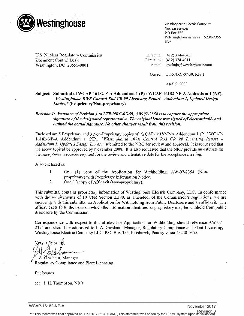
Subject: Submittal ofWCAP-16182-P-A Addendum 1 (P) I WCAP-16182-NP-A Addendum 1 (NP), "Westinghouse BWR Control Rod CR 99 Licensing Report- Addendum 1, Updated Design Limits," (Proprietary/Non-proprietary)
Revision 1: Issuance of Revision 1 to LTR-NRC-07-59, AW-07-2354 is to capture the appropriate signature of the designated representative. The original letter was signed off electronically and omitted the actual signature. No other changes result from this revision.
Enclosed are 5 Proprietary and 3 Non-Proprietary copies of WCAP-16182-P-A Addendum 1 (P) I WCAP-16182-NP-A Addendum 1 (NP), "Westinghouse BWR Control Rod CR 99 Licensing Report -Addendum 1, Updated Design Limits," submitted to the NRC for review and approval. It is requested that the above topical be approved by November 2008. It is also requested that the NRC provide an estimate on the man-power resources required for the review and a tentative date for the acceptance meeting.
Also enclosed is:
1. One (1) copy of the Application for Withholding, A W-07-2354 (Nonproprietary) with Proprietary Information Notice.
2. One (1) copy of Affidavit (Non-proprietary).
This submittal contains proprietary information of Westinghouse Electric Company, LLC. In conformance with the requirements of 10 CPR Section 2.390, as amended, of the Commission's regulations, we are enclosing with this submittal an Application for Withholding from Public Disclosure and an affidavit. The affidavit sets forth the basis on which the information identified as proprietary may be withheld from public disclosure by the Commission.
Correspondence with respect to this affidavit or Application for Withholding should reference AW-07-2354 and should be addressed to J. A. Gresham, Manager, Regulatory Compliance and Plant Licensing, Westinghouse Electric Company LLC, P.O. Box 355, Pittsburgh, Pennsylvania 15230-0355.
Enclosures
cc: J. H. Thompson, NRR
WCAP-16182-NP-A_____________________________________________________________________________________
November 2017 Revision 3
*** This record was final approved on 11/9/2017 3:13:35 AM. ( This statement was added by the PRIME system upon its validation)
WCAP-16182-NP-A_____________________________________________________________________________________
November 2017 Revision 3
*** This record was final approved on 11/9/2017 3:13:35 AM. ( This statement was added by the PRIME system upon its validation)
WCAP-16182-NP-A_____________________________________________________________________________________
November 2017 Revision 3
*** This record was final approved on 11/9/2017 3:13:35 AM. ( This statement was added by the PRIME system upon its validation)
WCAP-16182-NP-A_____________________________________________________________________________________
November 2017 Revision 3
*** This record was final approved on 11/9/2017 3:13:35 AM. ( This statement was added by the PRIME system upon its validation)
WCAP-16182-NP-A_____________________________________________________________________________________
November 2017 Revision 3
*** This record was final approved on 11/9/2017 3:13:35 AM. ( This statement was added by the PRIME system upon its validation)
WCAP-16182-NP-A_____________________________________________________________________________________
November 2017 Revision 3
*** This record was final approved on 11/9/2017 3:13:35 AM. ( This statement was added by the PRIME system upon its validation)
WCAP-16182-NP-A_____________________________________________________________________________________
November 2017 Revision 3
*** This record was final approved on 11/9/2017 3:13:35 AM. ( This statement was added by the PRIME system upon its validation)

Westinghouse Electric Company Nuclear Services P.O. Box 355 Pittsburgh, Pennsylvania 15230-0355 USA
Direct tel: (412) 374-4643 Direct fax: (412) 374-3846
e-mail: [email protected]
U.S. Nuclear Regulatory Commission Document Control Desk Washington, DC 20555-0001
LTR-NRC-09-50
November 10, 2009
Subject: Response to NRC Request for Additional Information Re: Westinghouse Electric Company Topical Report (TR) WCAP-16182-P-A, Addendum 1, “Westinghouse BWR Control Rod CR 99 Licensing Report - Addendum 1, Updated Design Limits,” dated November 6, 2008 (TAC NO. MD7989) and
Submittal of WCAP-16182-P-A/WCAP-16182-NP-A, Revision 1, “Westinghouse BWR Control Rod CR 99 Licensing Report - Update to Mechanical Design Limits,” dated October 2009 (Proprietary/Non-Proprietary).
Enclosed are Proprietary (P) and Non-Proprietary (NP) copies of responses and requested supporting information to the NRC’s Request for Additional Information (RAI), Re: Westinghouse Electric Company Topical Report (TR) WCAP-16182-P-A, Addendum 1, “Westinghouse BWR Control Rod CR 99 Licensing Report - Addendum 1, Updated Design Limits,” dated November 6, 2008. As follow-up to the actions discussed between Westinghouse’s Tom Rodack and NRC Branch Chief Tony Mendiola on March 11-12, 2009, and later with the NRC review staff during a teleconference on March 18, 2009, this response submits a revised and reformatted Revision 1 version of the proposed update to the CR 99 control rod design limits previously submitted as WCAP-16182-P-A, Addendum 1. The enclosed P and NP copies of WCAP-16182-P-A/NP-A, Revision 1, “Westinghouse BWR Control Rod CR 99 Licensing Report - Update to Mechanical Design Limits,” are provided to incorporate overall staff comments and to supersede the previous Addendum 1 version of the proposed update to the CR 99 topical design report in its entirety. Also as requested in the RAI, copies of proprietary references (Refs. 33-37) added by Revision 1, are enclosed for staff information in support of the proposed topical review. Should additional information be needed in regard to the enclosed response, please contact Michael Riggs in Westinghouse Fuel Engineering Licensing at 254-396-6392. Also enclosed is:
1. One (1) copy of the Application for Withholding, AW-09-2700 (Non-Proprietary) with Proprietary Information Notice.
2. One (1) copy of Affidavit (Non-Proprietary). This submittal contains proprietary information of Westinghouse Electric Company, LLC. In conformance with the requirements of 10 CFR Section 2.390, as amended, of the Commission’s regulations, we are enclosing with this submittal an Application for Withholding from Public Disclosure and an affidavit. The affidavit sets forth the basis on which the information identified as proprietary may be withheld from public disclosure by the Commission. Correspondence with respect to the affidavit or Application for Withholding should reference AW-09-2700 and should be addressed to J. A. Gresham, Manager, Regulatory Compliance and Plant Licensing, Westinghouse Electric Company LLC, P.O. Box 355, Pittsburgh, Pennsylvania 15230-0355.
WCAP-16182-NP-A_____________________________________________________________________________________
November 2017 Revision 3
*** This record was final approved on 11/9/2017 3:13:35 AM. ( This statement was added by the PRIME system upon its validation)
WCAP-16182-NP-A_____________________________________________________________________________________
November 2017 Revision 3
*** This record was final approved on 11/9/2017 3:13:35 AM. ( This statement was added by the PRIME system upon its validation)
WCAP-16182-NP-A_____________________________________________________________________________________
November 2017 Revision 3
*** This record was final approved on 11/9/2017 3:13:35 AM. ( This statement was added by the PRIME system upon its validation)

WCAP-16182-NP-A_____________________________________________________________________________________
November 2017 Revision 3
*** This record was final approved on 11/9/2017 3:13:35 AM. ( This statement was added by the PRIME system upon its validation)

AW-09-2700
-2-
(1) I am Manager, Regulatory Compliance and Plant Licensing, in Nuclear Services, Westinghouse Electric
Company LLC (Westinghouse) and as such, I have been specifically delegated the function of reviewing the
proprietary information sought to be withheld from public disclosure in connection with nuclear power plant
licensing and rulemaking proceedings, and am authorized to apply for its withholding on behalf of
Westinghouse.
(2) I am making this Affidavit in conformance with the provisions of 10 CFR Section 2.390 of the Commission's
regulations and in conjunction with the Westinghouse "Application for Withholding" accompanying this
Affidavit.
(3) I have personal knowledge of the criteria and procedures utilized by Westinghouse in designating information
as a trade secret, privileged or as confidential commercial or financial information.
(4) Pursuant to the provisions of paragraph (b)(4) of Section 2.390 of the Commission's regulations, the following
is furnished for consideration by the Commission in determining whether the information sought to be
withheld from public disclosure should be withheld.
(i) The information sought to be withheld from public disclosure is owned and has been held in
confidence by Westinghouse.
(ii) The information is of a type customarily held in confidence by Westinghouse and not customarily
disclosed to the public. Westinghouse has a rational basis for determining the types of information
customarily held in confidence by it and, in that connection, utilizes a system to determine when and
whether to hold certain types of information in confidence. The application of that system and the
substance of that system constitutes Westinghouse policy and provides the rational basis required.
Under that system, information is held in confidence if it falls in one or more of several types, the
release of which might result in the loss of an existing or potential competitive advantage, as follows:
(a) The information reveals the distinguishing aspects of a process (or component, structure,
tool, method, etc.) where prevention of its use by any of Westinghouse's competitors
without license from Westinghouse constitutes a competitive economic advantage over
other companies.
(b) It consists of supporting data, including test data, relative to a process (or component,
structure, tool, method, etc.), the application of which data secures a competitive
economic advantage, e.g., by optimization or improved marketability.
(c) Its use by a competitor would reduce his expenditure of resources or improve his
competitive position in the design, manufacture, shipment, installation, assurance of
quality, or licensing a similar product.
WCAP-16182-NP-A_____________________________________________________________________________________
November 2017 Revision 3
*** This record was final approved on 11/9/2017 3:13:35 AM. ( This statement was added by the PRIME system upon its validation)
AW-09-2700
-3-
(d) It reveals cost or price information, production capacities, budget levels, or commercial
strategies of Westinghouse, its customers or suppliers.
(e) It reveals aspects of past, present, or future Westinghouse or customer funded
development plans and programs of potential commercial value to Westinghouse.
(f) It contains patentable ideas, for which patent protection may be desirable.
There are sound policy reasons behind the Westinghouse system which include the following:
(a) The use of such information by Westinghouse gives Westinghouse a competitive
advantage over its competitors. It is, therefore, withheld from disclosure to protect the
Westinghouse competitive position.
(b) It is information which is marketable in many ways. The extent to which such
information is available to competitors diminishes the Westinghouse ability to sell
products and services involving the use of the information.
(c) Use by our competitor would put Westinghouse at a competitive disadvantage by reducing his expenditure of resources at our expense.
(d) Each component of proprietary information pertinent to a particular competitive
advantage is potentially as valuable as the total competitive advantage. If competitors
acquire components of proprietary information, any one component may be the key to the
entire puzzle, thereby depriving Westinghouse of a competitive advantage.
(e) Unrestricted disclosure would jeopardize the position of prominence of Westinghouse in
the world market, and thereby give a market advantage to the competition of those
countries.
(f) The Westinghouse capacity to invest corporate assets in research and development
depends upon the success in obtaining and maintaining a competitive advantage.
(iii) The information is being transmitted to the Commission in confidence and, under the provisions of
10 CFR Section 2.390, it is to be received in confidence by the Commission.
(iv) The information sought to be protected is not available in public sources or available information has
not been previously employed in the same original manner or method to the best of our knowledge
and belief.
WCAP-16182-NP-A_____________________________________________________________________________________
November 2017 Revision 3
*** This record was final approved on 11/9/2017 3:13:35 AM. ( This statement was added by the PRIME system upon its validation)
AW-09-2700
-4-
(v) The proprietary information sought to be withheld in this submittal is that which is appropriately
marked “Response to NRC Request for Additional Information Re: Westinghouse Electric Company
Topical Report (TR) WCAP-16182-P-A, Addendum 1, ‘Westinghouse BWR Control Rod CR 99
Licensing Report - Addendum 1, Updated Design Limits,’ dated November 6, 2008 (TAC NO.
MD7989) and Submittal of WCAP-16182-P-A/WCAP-16182-NP-A, Revision 1, “Westinghouse
BWR Control Rod CR 99 Licensing Report - Update to Mechanical Design Limits,” dated October
2009 (Proprietary/Non-proprietary),” and information only copies of the following proprietary
references (Revision 1 References 33-37);
(33.) Westinghouse Report, BTK 06-1597, “Mechanical Design Report CR 99 Control Rods for
S-Lattice BWR6,” dated 2007 (Proprietary),
(34.) Westinghouse Report BTM 09-0624, G. Eriksson, “BWR Control Rod CR 99 for BWR/2-4
and BWR/6 Reactors with D- and S-Lattice. Mechanical End of Life prediction and Stress
analysis,” dated 2009 (Proprietary),
(35.) Westinghouse Report BTF 06-1583, “Nuclear Design Characteristics of Westinghouse
Control Rod CR 99 for BWR6 S-Lattice Reactors,” dated 2007 (Proprietary),
(36.) Westinghouse Report BTF 06-1584, “Nuclear Design Characteristics of Westinghouse
Control Rod CR 99 for BWR2/3/4 D-Lattice Reactors,” dated 2007 (Proprietary), and
(37.) Westinghouse Report BTF 06-1623, “Nuclear Design Characteristics of Westinghouse
Control Rod CR 99 for BWR4/5 C-Lattice Reactors,” dated 2007 (Proprietary),
for submittal to the Commission, being transmitted by Westinghouse letter (LTR-NRC-09-50) and
Application for Withholding Proprietary Information from Public Disclosure, to the Document
Control Desk. The proprietary information as submitted by Westinghouse Electric Company is that
associated with the response to NRC Request for Additional Information Re: Westinghouse Electric
Company Topical Report (TR) WCAP-16182-P-A, Addendum 1, dated November 6, 2008.
This information is part of that which will enable Westinghouse to:
(a) Obtain generic NRC licensed approval for revised design criteria which will allow for
extended component life of the Westinghouse CR 99 BWR control rods.
(b) Meet NRC regulatory requirements in support of a Westinghouse product.
Further, this information has substantial commercial value as follows:
(a) Westinghouse can use this topical design report to further enhance their licensing position
over their competitors.
(b) Assist customers to obtain license changes.
Public disclosure of this proprietary information is likely to cause substantial harm to the competitive
position of Westinghouse because it would enhance the ability of competitors to provide similar
WCAP-16182-NP-A_____________________________________________________________________________________
November 2017 Revision 3
*** This record was final approved on 11/9/2017 3:13:35 AM. ( This statement was added by the PRIME system upon its validation)
AW-09-2700
-5-
technical evaluation justifications and licensing defense services for commercial power reactors
without commensurate expenses. Also, public disclosure of the information would enable others to
use the information to meet NRC requirements for licensing documentation without purchasing the
right to use the information.
The development of the technology described in part by the information is the result of applying the
results of many years of experience in an intensive Westinghouse effort and the expenditure of a
considerable sum of money.
In order for competitors of Westinghouse to duplicate this information, similar technical programs
would have to be performed and a significant manpower effort, having the requisite talent and
experience, would have to be expended.
Further the deponent sayeth not.
WCAP-16182-NP-A_____________________________________________________________________________________
November 2017 Revision 3
*** This record was final approved on 11/9/2017 3:13:35 AM. ( This statement was added by the PRIME system upon its validation)

PROPRIETARY INFORMATION NOTICE
Transmitted herewith are proprietary and/or non-proprietary versions of documents furnished to the NRC in
connection with requests for generic and/or plant-specific review and approval.
In order to conform to the requirements of 10 CFR 2.390 of the Commission's regulations concerning the protection
of proprietary information so submitted to the NRC, the information which is proprietary in the proprietary versions
is contained within brackets, and where the proprietary information has been deleted in the non-proprietary versions,
only the brackets remain (the information that was contained within the brackets in the proprietary versions having
been deleted). The justification for claiming the information so designated as proprietary is indicated in both
versions by means of lower case letters (a) through (f) located as a superscript immediately following the brackets
enclosing each item of information being identified as proprietary or in the margin opposite such information.
These lower case letters refer to the types of information Westinghouse customarily holds in confidence identified in
Sections (4)(ii)(a) through (4)(ii)(f) of the affidavit accompanying this transmittal pursuant to 10 CFR 2.390(b)(1).
COPYRIGHT NOTICE
The reports transmitted herewith each bear a Westinghouse copyright notice. The NRC is permitted to make the
number of copies of the information contained in these reports which are necessary for its internal use in connection
with generic and plant-specific reviews and approvals as well as the issuance, denial, amendment, transfer, renewal,
modification, suspension, revocation, or violation of a license, permit, order, or regulation subject to the
requirements of 10 CFR 2.390 regarding restrictions on public disclosure to the extent such information has been
identified as proprietary by Westinghouse, copyright protection notwithstanding. With respect to the
non-proprietary versions of these reports, the NRC is permitted to make the number of copies beyond those
necessary for its internal use which are necessary in order to have one copy available for public viewing in the
appropriate docket files in the public document room in Washington, DC and in local public document rooms as
may be required by NRC regulations if the number of copies submitted is insufficient for this purpose. Copies made
by the NRC must include the copyright notice in all instances and the proprietary notice if the original was identified
as proprietary.
WCAP-16182-NP-A_____________________________________________________________________________________
November 2017 Revision 3
*** This record was final approved on 11/9/2017 3:13:35 AM. ( This statement was added by the PRIME system upon its validation)
. Westinghouse Westinghouse Electric CompanyNuclear ServicesP.O. Box 355Pittsburgh. Pennsylvania 15230-0355USA
u.s. Nuclear Regulatory CommissionDocument Control DeskWashington, DC 20555-0001
Direct tel: (412) 374-4643Direct fax: (412) 374-4011
e-mail: greshaja(?westinghouse.com
LTR-NRC-10-18
March 24, 2010
Subject: Request to withdraw Westinghouse Topical Report WCAP-16182-P-A Addendum 1 /WCAP-16182-NP-A Addendum 1, "Westinghouse BWR Control Rod CR 99 LicensingReport - Addendum 1, Updated Design Limits," (ProprietalNon-Proprieta) (TAC
NO.MD7989)
References: 1) J. A. Gresham, Westinghouse, letter to the USNRC, "Submittl ofWCAP-16182-P-AAddendum 1 (P) / WCAP-16182-NP-A Addendum i (NP), "Westinghouse BWR ControlRod CR 99 Licensing Report - Addendum 1, Updated Design Limits," (ProprietalNon-
Proprieta) LTR-NRC-07-59, Rev. 1, April 9, 2008.
2) S. L. Rosenberg, NRC, letter to J. A. Gresham, Westinghouse, "Acceptance ForReview of Westinghouse Electrc Company Topical Report (TR) WCAP-16182-P,Addendum 1, 'BWR Control Rod CR 99 Licensing Report - Addendum 1, UpdatedDesign Limits,' (TAC NO. MD7989)," April 28, 2008.
3) J. A. Gresham, Westinghouse, letter to the USNRC, "Response to NRC Request forAdditional Information Re: Westinghouse Electric Company Topical Report (TR)WCAP-16182-P-A, Addendum 1, 'Westinghouse BWR Contrl Rod CR 99 LicensingReport - Addendum 1, Updated Design Limits,' dated November 6,2008 (TAC NO.MD7989) and Submitt ofWCAP-16182-P-AlWCAP-16182-NP-A, Revision 1,'Westighouse BWR Control Rod CR 99 Licensing Report - Update to MechanicalDesign Limits,' dated October 2009 (ProprietalNon-Proprieta)," LTR-NRC-09-50,November 10,2009.
4) S. L. Rosenberg, NRC, letter to J. A. Gresham, Westinghouse, "Acceptance ForReview of Westinghouse Electrc Company Topical Report (TR) WCAP-16182-P,Revision 1, 'Westinghouse BWR Control Rod CR 99 Licensing Report - Update toMechanical Design Limits,' (TAC NO. ME2630)," Januar 5, 2010.
Dear Sirs:
Based on the revised submittl (Reference 3) and acceptace for NRC review (Reference 4) ofWCAP-16182-P-A Revision 1 / WCAP-16182-NP-A, Revision 1, "Westinghouse BWR Control Rod CR 99Licensing Report - Update to Mechanical Design Limits," Westinghouse respectflly requests towithdraw the Addendum 1 version of this topicaL. Addendum 1 was originally submitted by Reference 1and accepted for NRC review by Reference 2. The Revision 1 version of the submittl is intended toincorporate sta comments, and supersede the previously submitted Addendum 1.
WCAP-16182-NP-A_____________________________________________________________________________________
November 2017 Revision 3
*** This record was final approved on 11/9/2017 3:13:35 AM. ( This statement was added by the PRIME system upon its validation)
LTR-NRC-IO-18March 24,2010
If you have fuher questions regarding this request, please contact Kris Cummings, Manager, FuelEngineering Licensing or Michael Riggs, Fuel Engineering Licensing.
s...Jnc1;.e eii.y y". I /1.1'g~~-lI J. A. Gresham, Manager
Regulatory Compliance and Plant Licensing
cc: E. Lenning, NRR
WCAP-16182-NP-A_____________________________________________________________________________________
November 2017 Revision 3
*** This record was final approved on 11/9/2017 3:13:35 AM. ( This statement was added by the PRIME system upon its validation)
inghouse
U.S. Nuclear Regulatory Commission Document Control Desk 11555 Rockville Pike Rockville, MD 20852
Westinghouse Electric Company 1000 Westinghouse Drive Cranberry Township, Pennsylvania 16066 USA
Direct tel: (412) 374-4643 Direct fax: (724) 940-8560
e-mail: [email protected]
LTR-NRC-15-89
November 3, 2015
Subject: Submittal ofWCAP-16182-P, Revision 2 and WCAP-16182-NP, Revision 2, "Westinghouse BWR Control Rod CR 99 Licensing Report - Update to Mechanical Design Limits," (Proprietary IN on-Proprietary)
Enclosed are the proprietary and non-proprietary versions of WCAP-16182, Revision 2, "Westinghouse BWR Control Rod CR 99 Licensing Report- Update to Mechanical Design Limits," dated October 2015, submitted for review and approval under the NRC's licensing topical report program for referencing in licensing actions.
By letter dated November 10, 2009 (LTR-NRC-09-50), Westinghouse submitted WCAP-16182-P-A/-NP-A, Revision 1, "Westinghouse BWR Control Rod CR 99 Licensing ReportUpdate to Mechanical Design Limits," for NRC review and approval. To address staff comments from an audit of the topical report conducted October 1-2, 2014 and a subsequent teleconference on April16, 2015, Revision 2 ofWCAP-16182-P/-NP was developed. Revision 2 ofWCAP-16182-P/-NP supersedes the previously submitted Revision 1.
Also enclosed are:
1. An Application for Withholding Proprietary Information from Public Disclosure, A W -15-4307 (NonProprietary) with Proprietary Information Notice and Copyright Notice
2. An Affidavit (Non-Proprietary).
This submittal contains proprietary information of Westinghouse Electric Company LLC. In conformance with the requirements of 10 CFR Section 2.390, as amended, of the Commission's regulations, we are enclosing with this submittal an Application for Withholding Proprietary Information from Public Disclosure and an Affidavit. The Mfidavit sets forth the basis on which the information identified as proprietary may be withheld from public disclosure by the Commission.
WCAP-16182-NP-A_____________________________________________________________________________________
November 2017 Revision 3
*** This record was final approved on 11/9/2017 3:13:35 AM. ( This statement was added by the PRIME system upon its validation)
LTR-NRC-15-89
Page 2 of2
Correspondence with respect to the proprietary aspects of the Application for Withholding or the Westinghouse Affidavit should reference AW-15-4307 and should be addressed to James A. Gresham, Manager, Regulatory Compliance, Westinghouse Electric Company, 1000 Westinghouse Drive, Building 3 Suite 310, Cranberry Township, Pennsylvania 16066.
Enclosures
cc: Ekaterina Lenning (NRR) Kevin Hsueh (NRR)
J~\v-l;ames A. Gresham, Manager
Regulatory Compliance
WCAP-16182-NP-A_____________________________________________________________________________________
November 2017 Revision 3
*** This record was final approved on 11/9/2017 3:13:35 AM. ( This statement was added by the PRIME system upon its validation)
e in house
U.S. Nuclear Regulatory Commission Document Control Desk 11555 Rockville Pike Rockville, MD 20852
Westinghouse Electric Company 1000 Westinghouse Drive Cranberry Township, Pennsylvania 16066 USA
Direct tel: (412) 374-4643 Direct fax: (724) 940-8560
e-mail: [email protected]
AW-15-4307
November 3, 2015
APPLICATION FOR WITHHOLDING PROPRIETARY INFORMATION FROM PUBLIC DISCLOSURE
Subject: WCAP-16182-P, Revision 2, "Westinghouse BWR Control Rod CR 99 Licensing ReportUpdate to Mechanical Design Limits" (Proprietary)
Reference: Letter from James A. Gresham to Document Control Desk, LTR-NRC-15-89, dated November 3, 2015
The Application for Withholding Proprietary Information from Public Disclosure is submitted by Westinghouse Electric Company LLC (Westinghouse), pursuant to the provisions of paragraph (b)(1) of Section 2.390 of the Commission's regulations. It contains commercial strategic information proprietary to Westinghouse and customarily held in confidence.
The proprietary information for which withholding is being requested in the above-referenced report is further identified in Affidavit A W -15-4307 signed by the owner of the proprietary information, Westinghouse Electric Company LLC. The Affidavit, which accompanies this letter, sets forth the basis on which the information may be withheld from public disclosure by the Commission and addresses with specificity the considerations listed in paragraph (b)(4) of 10 CFR Section 2.390 of the Commission's regulations.
Correspondence with respect to the proprietary aspects of this Application for Withholding or the accompanying Affidavit should reference AW-15-4307 and should be addressed to James A. Gresham, Manager, Regulatory Compliance, Westinghouse Electric Company, 1000 Westinghouse Drive, Building 3 Suite 310, Cranberry Township, Pennsylvania 16066.
A~~ /iames A. Gresham, Manager
Regulatory Compliance
WCAP-16182-NP-A_____________________________________________________________________________________
November 2017 Revision 3
*** This record was final approved on 11/9/2017 3:13:35 AM. ( This statement was added by the PRIME system upon its validation)
COMMONWEALTH OF PENNSYLVANIA:
COUNTY OF BUTLER:
AFFIDAVIT
ss
AW-15-4307 November 3, 2015
I, James A. Gresham, am authorized to execute this Affidavit on behalf of Westinghouse Electric
Company LLC (Westinghouse), and I declare under penalty of perjury that the foregoing is true and
correct.
IJ:mes A. Gresham, Manager
Regulatory Compliance
WCAP-16182-NP-A_____________________________________________________________________________________
November 2017 Revision 3
*** This record was final approved on 11/9/2017 3:13:35 AM. ( This statement was added by the PRIME system upon its validation)
2 AW-15-4307
(1) I am Manager, Regulatory Compliance, Westinghouse Electric Company LLC (Westinghouse),
and as such, I have been specifically delegated the function of reviewing the proprietary
information sought to be withheld from public disclosure in connection with nuclear power plant
licensing and rule making proceedings, and am authorized to apply for its withholding on behalf of
Westinghouse.
(2) I am making this Affidavit in conformance with the provisions of 10 CFR Section 2.390 of the
Commission's regulations and in conjunction with the Westinghouse Application for Withholding
Proprietary Information from Public Disclosure accompanying this Affidavit.
(3) I have personal knowledge of the criteria and procedures utilized by Westinghouse in designating
information as a trade secret, privileged or as confidential commercial or financial information.
( 4) Pursuant to the provisions of paragraph (b)( 4) of Section 2.390 of the Commission's regulations,
the following is furnished for consideration by the Commission in determining whether the
information sought to be withheld from public disclosure should be withheld.
(i) The information sought to be withheld from public disclosure is owned and has been held
in confidence by Westinghouse.
(ii) The information is of a type customarily held in confidence by Westinghouse and not
customarily disclosed to the public. Westinghouse has a rational basis for determining the
types of information customarily held in confidence by it and, in that connection, utilizes a
system to determine when and whether to hold certain types of information in confidence.
The application of that system and the substance of that system constitute Westinghouse
policy and provide the rational basis required.
Under that system, information is held in confidence if it falls in one or more of several
types, the release of which might result in the loss of an existing or potential competitive
advantage, as follows:
(a) The information reveals the distinguishing aspects of a process (or component,
structure, tool, method, etc.) where prevention of its use by any of Westinghouse's
WCAP-16182-NP-A_____________________________________________________________________________________
November 2017 Revision 3
*** This record was final approved on 11/9/2017 3:13:35 AM. ( This statement was added by the PRIME system upon its validation)
3 AW-15-4307
competitors without license from Westinghouse constitutes a competitive
economic advantage over other companies.
(b) It consists of supporting data, including test data, relative to a process (or
component, structure, tool, method, etc.), the application of which data secures a
competitive economic advantage, e.g., by optimization or improved _marketability.
(c) Its use by a competitor would reduce his expenditure of resources or improve his
competitive position in the design, manufacture, shipment, installation, assurance
of quality, or licensing a similar product.
(d) It reveals cost or price information, production capacities, budget levels, or
commercial strategies of Westinghouse, its customers or suppliers.
(e) It reveals aspects of past, present, or future Westinghouse or customer funded
development plans and programs of potential commercial value to Westinghouse.
(f) It contains patentable ideas, for which patent protection may be desirable.
(iii) There are sound policy reasons behind the Westinghouse system which include the
following:
(a) The use of such information by Westinghouse gives Westinghouse a competitive
advantage over its competitors. It is, therefore, withheld from disclosure to protect
the Westinghouse competitive position.
(b) It is information that is marketable in many ways. The extent to which such
information is available to competitors diminishes the Westinghouse ability to sell
products and services involving the use of the information.
(c) Use by our competitor would put Westinghouse at a competitive disadvantage by
reducing his expenditure of resources at our expense.
WCAP-16182-NP-A_____________________________________________________________________________________
November 2017 Revision 3
*** This record was final approved on 11/9/2017 3:13:35 AM. ( This statement was added by the PRIME system upon its validation)
4 AW-15-4307
(d) Each component of proprietary information pertinent to a particular competitive
advantage is potentially as valuable as the total competitive advantage. If
competitors acquire components of proprietary information, any one component
may be the key to the entire puzzle, thereby depriving Westinghouse of a
competitive advantage.
(e) Unrestricted disclosure would jeopardize the position of prominence of
Westinghouse in the world market, and thereby give a market advantage to the
competition of those countries.
(f) The Westinghouse capacity to invest corporate assets in research and development
depends upon the success in obtaining and maintaining a competitive advantage.
(iv) The information is being transmitted to the Commission in confidence and, under the
provisions of 10 CFR Section 2.390, it is to be received in confidence by the Commission.
(v) The information sought to be protected is not available in public sources or available
information has not been previously employed in the same original manner or method to
the best of our knowledge and belief.
(vi) The proprietary information sought to be withheld in this submittal is that which is
appropriately marked in WCAP-16182-P, Revision 2, "Westinghouse BWR Control Rod
CR 99 Licensing Report- Update to Mechanical Design Limits" (Proprietary), dated
October 2015, for submittal to the Commission, being transmitted by Westinghouse letter,
LTR-NRC-15-89, and Application for Withholding Proprietary Information from Public
Disclosure, to the Document Control Desk. The proprietary information as submitted by
Westinghouse is that associated with Westinghouse's request for NRC approval of
WCAP-16182-P, Revision 2, and may be used only for that purpose.
(a) This information is part of that which will enable Westinghouse to obtain NRC
approval ofWCAP-16182-P, Revision 2, "Westinghouse BWR Control Rod CR
99 Licensing Report- Update to Mechanical Design Limits."
WCAP-16182-NP-A_____________________________________________________________________________________
November 2017 Revision 3
*** This record was final approved on 11/9/2017 3:13:35 AM. ( This statement was added by the PRIME system upon its validation)
5 AW-15-4307
(b) Further this information has substantial commercial value as follows:
(i) Westinghouse plans to sell the use of similar information to its customers
for the purpose of improving the performance of Westinghouse BWR
control rods.
(ii) Westinghouse can sell support and defense of industry guidelines and
acceptance criteria for plant -specific applications.
(iii) The information requested to be withheld reveals the distinguishing
aspects of a methodology which was developed by Westinghouse.
Public disclosure of this proprietary information is likely to cause substantial harm to the
competitive position of Westinghouse because it would enhance the ability of competitors
to provide similar technical evaluation justifications and licensing defense services for
commercial power reactors without commensurate expenses. Also, public disclosure of the
information would enable others to use the information to meet NRC requirements for
licensing documentation without purchasing the right to use the information.
The development of the technology described in part by the information is the result of
applying the results of many years of experience in an intensive Westinghouse effort and
the expenditure of a considerable sum of money.
In order for competitors of Westinghouse to duplicate this information, similar technical
programs would have to be performed and a significant manpower effort, having the
requisite talent and experience, would have to be expended.
Further the deponent sayeth not.
WCAP-16182-NP-A_____________________________________________________________________________________
November 2017 Revision 3
*** This record was final approved on 11/9/2017 3:13:35 AM. ( This statement was added by the PRIME system upon its validation)
PROPRIETARY INFORMATION NOTICE
Transmitted herewith are proprietary and non-proprietary versions of documents furnished to the NRC in connection with requests for generic and/or plant-specific review and approval.
In order to conform to the requirements of 10 CFR 2.390 of the Commission's regulations concerning the protection of proprietary information so submitted to the NRC, the information which is proprietary in the proprietary versions is contained within brackets, and where the proprietary information has been deleted in the non-proprietary versions, only the brackets remain (the information that was contained within the brackets in the proprietary versions having been deleted). The justification for claiming the information so designated as proprietary is indicated in both versions by means of lower case letters (a) through (f) located as a superscript immediately following the brackets enclosing each item of information being identified as proprietary or in the margin opposite such information. These lower case letters refer to the types of information Westinghouse customarily holds in confidence identified in Sections ( 4)(ii)(a) through ( 4 )(ii)(f) of the Mfidavit accompanying this transmittal pursuant to 10 CFR 2.390(b )(1 ).
COPYRIGHT NOTICE
The reports transmitted herewith each bear a Westinghouse copyright notice. The NRC is permitted to make the number of copies of the information contained in these reports which are necessary for its internal use in connection with generic and plant-specific reviews and approvals as well as the issuance, denial, amendment, transfer, renewal, modification, suspension, revocation, or violation of a license, permit, order, or regulation subject to the requirements of 10 CFR 2.390 regarding restrictions on public disclosure to the extent such information has been identified as proprietary by Westinghouse, copyright protection notwithstanding. With respect to the non-proprietary versions of these reports, the NRC is permitted to make the number of copies beyond those necessary for its internal use which are necessary in order to have one copy available for public viewing in the appropriate docket files in the public document room in Washington, DC and in local public document rooms as may be required by NRC regulations if the number of copies submitted is insufficient for this purpose. Copies made by the NRC must include the copyright notice in all instances and the proprietary notice if the original was identified as proprietary.
WCAP-16182-NP-A_____________________________________________________________________________________
November 2017 Revision 3
*** This record was final approved on 11/9/2017 3:13:35 AM. ( This statement was added by the PRIME system upon its validation)
Westinghouse Non-Proprietary Class 3
in ouse
U.S. Nuclear Regulatory Commission Document Control Desk 11555 Rockville Pike Rockville, MD 20852
Westinghouse Electric Company 1000 Westinghouse Drive Cranberry Township, Pennsylvania 16066 USA
Direct tel: (412) 374-4643 Direct fax: (724) 940-8560
e-mail: [email protected]
LTR-NRC-16-42
June 27, 2016
Subject: Submittal ofWCAP-16182-P, Revision 3-Draft, and WCAP-16182-NP, Revision 3-Draft, "Westinghouse BWR Control Rod CR 99 Licensing Report- Update to Mechanical Design Limits" (Proprietary IN on-Proprietary)
Enclosed are the proprietary and non-proprietary versions ofWCAP-16182-P, Revision 3-Draft, "Westinghouse BWR Control Rod CR 99 Licensing Report- Update to Mechanical Design Limits," dated June 2016. Revision 3-Draft of this topical report incorporates the changes identified during the NRC Audit ofWCAP 16182-P, Revision 2, held on May 17-20,2016. This report is being issued to facilitate the preparation of the NRC's draft Safety Evaluation Report. The changes included in Revision 3-Draft of this report are identified in the Summary of Changes section and are marked with revision bars in the right margin.
Also enclosed are:
1. An Application for Withholding Proprietary Information from Public Disclosure, A W -16-443 7 with Proprietary Information Notice and Copyright Notice
2. An Affidavit (Non-Proprietary).
This submittal contains proprietary information of Westinghouse Electric Company LLC. In conformance with the requirements of 10 CFR Section 2.390, as amended, of the Commission's regulations, we are enclosing with this submittal an Application for Withholding Proprietary Information from Public Disclosure and an Affidavit. The Affidavit sets forth the basis on which the information identified as proprietary may be withheld from public disclosure by the Commission.
Correspondence with respect to the proprietary aspects of the Application for Withholding or the Westinghouse Affidavit should reference AW-16-4437 and should be addressed to James A. Gresham, Manager, Regulatory Compliance, Westinghouse Electric Company, 1000 Westinghouse Drive, Building 3 Suite 310, Cranberry Township, Pennsy~
~ames A. Gresham, Manager Regulatory Compliance
Enclosures
cc: Ekaterina Lenning (NRC) Kevin Hsueh (NRC)
© 2016 Westinghouse Electric Company LLC. All Rights Reserved. WCAP-16182-NP-A_____________________________________________________________________________________
November 2017 Revision 3
*** This record was final approved on 11/9/2017 3:13:35 AM. ( This statement was added by the PRIME system upon its validation)
Westinghouse Non-Proprietary Class 3
in ouse Westinghouse Electric Company 1000 Westinghouse Drive Cranberry Township, Pennsylvania 16066 USA
U.S. Nuclear Regulatory Commission Document Control Desk
Direct tel: ( 412) 374-4643 Direct fax: (724) 940-8560
11555 Rockville Pike Rockville, MD 20852
e-mail: [email protected]
AW-16-4437
June 27, 2016
APPLICATION FOR WITHHOLDING PROPRIETARY INFORMATION FROM PUBLIC DISCLOSURE
Subject: WCAP-16182-P, Revision 3-Draft, "Westinghouse BWR Control Rod CR 99 Licensing Report- Update to Mechanical Design Limits" (Proprietary)
Reference: Letter from James A. Gresham to Document Control Desk, LTR-NRC-16-42, June 27,2016
The Application for Withholding Proprietary Information from Public Disclosure is submitted by Westinghouse Electric Company LLC (Westinghouse), pursuant to the provisions of paragraph (b)(l) of Section 2.390 of the Commission's regulations. It contains commercial strategic information proprietary to Westinghouse and customarily held in confidence.
The proprietary information for which withholding is being requested in the above-referenced report is further identified in Affidavit A W -16-4437 signed by the owner of the proprietary information, Westinghouse Electric Company LLC. The Mfidavit, which accompanies this letter, sets forth the basis on which the information may be withheld from public disclosure by the Commission and addresses with specificity the considerations listed in paragraph (b)( 4) of 10 CFR Section 2.390 of the Commission's regulations.
Correspondence with respect to the proprietary aspects of this Application for Withholding or the accompanying Affidavit should reference AW-16-4437 and should be addressed to James A. Gresham, Manager, Regulatory Compliance, Westinghouse Electric Company, 1000 Westinghouse Drive, Building 3 Suite 310, Cranberry Township, Pennsylvania 16066.
J~~ger Regulatory Compliance
WCAP-16182-NP-A_____________________________________________________________________________________
November 2017 Revision 3
*** This record was final approved on 11/9/2017 3:13:35 AM. ( This statement was added by the PRIME system upon its validation)
COMMONWEALTH OF PENNSYLVANIA:
COUNTY OF BUTLER:
AFFIDAVIT
ss
AW-16-4437
June 27, 2016
I, James A. Gresham, am authorized to execute this Affidavit on behalf of Westinghouse Electric
Company LLC (Westinghouse), and that the averments of fact set forth in this Affidavit are true and
correct to the best of my knowledge, information, and belief.
Regulatory Compliance
WCAP-16182-NP-A_____________________________________________________________________________________
November 2017 Revision 3
*** This record was final approved on 11/9/2017 3:13:35 AM. ( This statement was added by the PRIME system upon its validation)
AW-16-4437
2
(1) I am Manager, Regulatory Compliance, Westinghouse Electric Company LLC (Westinghouse),
and as such, I have been specifically delegated the function of reviewing the proprietary
information sought to be withheld from public disclosure in connection with nuclear power plant
licensing and rule making proceedings, and am authorized to apply for its withholding on behalf
of Westinghouse.
(2) I am making this Affidavit in conformance with the provisions of 10 CFR Section 2.390 of the
Commission’s regulations and in conjunction with the Westinghouse Application for Withholding
Proprietary Information from Public Disclosure accompanying this Affidavit.
(3) I have personal knowledge of the criteria and procedures utilized by Westinghouse in designating
information as a trade secret, privileged or as confidential commercial or financial information.
(4) Pursuant to the provisions of paragraph (b)(4) of Section 2.390 of the Commission’s regulations,
the following is furnished for consideration by the Commission in determining whether the
information sought to be withheld from public disclosure should be withheld.
(i) The information sought to be withheld from public disclosure is owned and has been held
in confidence by Westinghouse.
(ii) The information is of a type customarily held in confidence by Westinghouse and not
customarily disclosed to the public. Westinghouse has a rational basis for determining
the types of information customarily held in confidence by it and, in that connection,
utilizes a system to determine when and whether to hold certain types of information in
confidence. The application of that system and the substance of that system constitute
Westinghouse policy and provide the rational basis required.
Under that system, information is held in confidence if it falls in one or more of several
types, the release of which might result in the loss of an existing or potential competitive
advantage, as follows:
(a) The information reveals the distinguishing aspects of a process (or component,
structure, tool, method, etc.) where prevention of its use by any of
WCAP-16182-NP-A_____________________________________________________________________________________
November 2017 Revision 3
*** This record was final approved on 11/9/2017 3:13:35 AM. ( This statement was added by the PRIME system upon its validation)

AW-16-4437
3
Westinghouse’s competitors without license from Westinghouse constitutes a
competitive economic advantage over other companies.
(b) It consists of supporting data, including test data, relative to a process (or
component, structure, tool, method, etc.), the application of which data secures a
competitive economic advantage, e.g., by optimization or improved
marketability.
(c) Its use by a competitor would reduce his expenditure of resources or improve his
competitive position in the design, manufacture, shipment, installation, assurance
of quality, or licensing a similar product.
(d) It reveals cost or price information, production capacities, budget levels, or
commercial strategies of Westinghouse, its customers or suppliers.
(e) It reveals aspects of past, present, or future Westinghouse or customer funded
development plans and programs of potential commercial value to Westinghouse.
(f) It contains patentable ideas, for which patent protection may be desirable.
(iii) There are sound policy reasons behind the Westinghouse system which include the
following:
(a) The use of such information by Westinghouse gives Westinghouse a competitive
advantage over its competitors. It is, therefore, withheld from disclosure to
protect the Westinghouse competitive position.
(b) It is information that is marketable in many ways. The extent to which such
information is available to competitors diminishes the Westinghouse ability to
sell products and services involving the use of the information.
(c) Use by our competitor would put Westinghouse at a competitive disadvantage by
reducing his expenditure of resources at our expense.
WCAP-16182-NP-A_____________________________________________________________________________________
November 2017 Revision 3
*** This record was final approved on 11/9/2017 3:13:35 AM. ( This statement was added by the PRIME system upon its validation)
AW-16-4437
4
(d) Each component of proprietary information pertinent to a particular competitive
advantage is potentially as valuable as the total competitive advantage. If
competitors acquire components of proprietary information, any one component
may be the key to the entire puzzle, thereby depriving Westinghouse of a
competitive advantage.
(e) Unrestricted disclosure would jeopardize the position of prominence of
Westinghouse in the world market, and thereby give a market advantage to the
competition of those countries.
(f) The Westinghouse capacity to invest corporate assets in research and
development depends upon the success in obtaining and maintaining a
competitive advantage.
(iv) The information is being transmitted to the Commission in confidence and, under the
provisions of 10 CFR Section 2.390, is to be received in confidence by the Commission.
(v) The information sought to be protected is not available in public sources or available
information has not been previously employed in the same original manner or method to
the best of our knowledge and belief.
(vi) The proprietary information sought to be withheld in this submittal is that which is
appropriately marked in WCAP-16182-P, Revision 3-Draft, “Westinghouse BWR
Control Rod CR 99 Licensing Report – Update to Mechanical Design Limits”
(Proprietary), dated June 2016, for submittal to the Commission, being transmitted by
Westinghouse Letter, LTR-NRC-16-42, and Application for Withholding Proprietary
Information from Public Disclosure, to the Document Control Desk. The proprietary
information as submitted by Westinghouse is that associated with NRC approval of
WCAP-16182-P and may be used only for that purpose.
WCAP-16182-NP-A_____________________________________________________________________________________
November 2017 Revision 3
*** This record was final approved on 11/9/2017 3:13:35 AM. ( This statement was added by the PRIME system upon its validation)
AW-16-4437
5
(a) This information is part of that which will enable Westinghouse to obtain NRC
approval of the application of the Westinghouse design and analysis
methodology related to the CR 99 Control Rod Design, as documented in
WCAP-16182-P, Rev. 3-Draft.
(b) Further, this information has substantial commercial value as follows:
(i) Westinghouse plans to sell the use of similar information to its customers
for the purpose of assisting customers in utilizing the improved design
parameters of the CR 99 Control Rods.
(ii) Westinghouse can sell support and defense of the licensing of these
control rods for plant-specific applications.
(iii) The information requested to be withheld reveals the distinguishing
aspects of a methodology which was developed by Westinghouse.
Public disclosure of this proprietary information is likely to cause substantial harm to the
competitive position of Westinghouse because it would enhance the ability of
competitors to provide similar technical evaluation justifications and licensing defense
services for commercial power reactors without commensurate expenses. Also, public
disclosure of the information would enable others to use the information to meet NRC
requirements for licensing documentation without purchasing the right to use the
information.
The development of the technology described in part by the information is the result of
applying the results of many years of experience in an intensive Westinghouse effort and
the expenditure of a considerable sum of money.
In order for competitors of Westinghouse to duplicate this information, similar technical
programs would have to be performed and a significant manpower effort, having the
requisite talent and experience, would have to be expended.
Further the deponent sayeth not.
WCAP-16182-NP-A_____________________________________________________________________________________
November 2017 Revision 3
*** This record was final approved on 11/9/2017 3:13:35 AM. ( This statement was added by the PRIME system upon its validation)
PROPRIETARY INFORMATION NOTICE Transmitted herewith are proprietary and non-proprietary versions of a document, furnished to the NRC in connection with requests for generic and/or plant specific review and approval. In order to conform to the requirements of 10 CFR 2.390 of the Commission’s regulations concerning the protection of proprietary information so submitted to the NRC, the information which is proprietary in the proprietary versions is contained within brackets, and where the proprietary information has been deleted in the non-proprietary versions, only the brackets remain (the information that was contained within the brackets in the proprietary versions having been deleted). The justification for claiming the information so designated as proprietary is indicated in both versions by means of lower case letters (a) through (f) located as a superscript immediately following the brackets enclosing each item of information being identified as proprietary or in the margin opposite such information. These lower case letters refer to the types of information Westinghouse customarily holds in confidence identified in Sections (4)(ii)(a) through (4)(ii)(f) of the Affidavit accompanying this transmittal pursuant to 10 CFR 2.390(b)(1).
COPYRIGHT NOTICE The reports transmitted herewith each bear a Westinghouse copyright notice. The NRC is permitted to make the number of copies of the information contained in these reports which are necessary for its internal use in connection with generic and plant-specific reviews and approvals as well as the issuance, denial, amendment, transfer, renewal, modification, suspension, revocation, or violation of a license, permit, order, or regulation subject to the requirements of 10 CFR 2.390 regarding restrictions on public disclosure to the extent such information has been identified as proprietary by Westinghouse, copyright protection notwithstanding. With respect to the non-proprietary versions of these reports, the NRC is permitted to make the number of copies beyond those necessary for its internal use which are necessary in order to have one copy available for public viewing in the appropriate docket files in the public document room in Washington, DC and in local public document rooms as may be required by NRC regulations if the number of copies submitted is insufficient for this purpose. Copies made by the NRC must include the copyright notice in all instances and the proprietary notice if the original was identified as proprietary.
WCAP-16182-NP-A_____________________________________________________________________________________
November 2017 Revision 3
*** This record was final approved on 11/9/2017 3:13:35 AM. ( This statement was added by the PRIME system upon its validation)
WCAP-16182-NP-A_____________________________________________________________________________________
November 2017 Revision 3
*** This record was final approved on 11/9/2017 3:13:35 AM. ( This statement was added by the PRIME system upon its validation)
WCAP-16182-NP-A_____________________________________________________________________________________
November 2017 Revision 3
*** This record was final approved on 11/9/2017 3:13:35 AM. ( This statement was added by the PRIME system upon its validation)
WCAP-16182-NP-A_____________________________________________________________________________________
November 2017 Revision 3
*** This record was final approved on 11/9/2017 3:13:35 AM. ( This statement was added by the PRIME system upon its validation)
WCAP-16182-NP-A_____________________________________________________________________________________
November 2017 Revision 3
*** This record was final approved on 11/9/2017 3:13:35 AM. ( This statement was added by the PRIME system upon its validation)

WCAP-16182-NP-A_____________________________________________________________________________________
November 2017 Revision 3
*** This record was final approved on 11/9/2017 3:13:35 AM. ( This statement was added by the PRIME system upon its validation)
WCAP-16182-NP-A_____________________________________________________________________________________
November 2017 Revision 3
*** This record was final approved on 11/9/2017 3:13:35 AM. ( This statement was added by the PRIME system upon its validation)

WCAP-16182-NP-A_____________________________________________________________________________________
November 2017 Revision 3
*** This record was final approved on 11/9/2017 3:13:35 AM. ( This statement was added by the PRIME system upon its validation)
WCAP-16182-NP-A_____________________________________________________________________________________
November 2017 Revision 3
*** This record was final approved on 11/9/2017 3:13:35 AM. ( This statement was added by the PRIME system upon its validation)
Westinghouse Non-Proprietary Class 3 ii
WCAP-16182-NP-A November 2017 Revision 3
TABLE OF CONTENTS
LIST OF TABLES ........................................................................................................................................ v
LIST OF FIGURES ..................................................................................................................................... vi
EXECUTIVE SUMMARY ......................................................................................................................... vii
SUMMARY OF CHANGES ..................................................................................................................... viii
1 PURPOSE ..................................................................................................................................... 1-1 2 INTRODUCTION ........................................................................................................................ 2-1
2.1 BASIC WESTINGHOUSE DESIGN .............................................................................. 2-1 2.2 LICENSING BACKGROUND ....................................................................................... 2-1 2.3 CURRENT/FUTURE DEVELOPMENTS ..................................................................... 2-2
3 DEFINITIONS .............................................................................................................................. 3-1 3.1 CR 99 CONTROL ROD .................................................................................................. 3-1 3.2 CONFORMANCE METHODS....................................................................................... 3-1 3.3 CRITERIA ....................................................................................................................... 3-1 3.4 CRITICAL ATTRIBUTES .............................................................................................. 3-1 3.5 DESIGN REQUIREMENTS ........................................................................................... 3-1
4 DESIGN REQUIREMENTS ........................................................................................................ 4-1 4.1 GENERAL ....................................................................................................................... 4-1 4.2 CONFORMANCE METHODS....................................................................................... 4-1
5 MATERIALS EVALUATION ...................................................................................................... 5-1 5.1 CRITICAL ATTRIBUTES .............................................................................................. 5-1 5.2 CRITICAL ATTRIBUTES DISCUSSION ...................................................................... 5-1
5.2.1 Rod Wing and Handle Material ....................................................................... 5-1 5.2.2 Button and Roller Material .............................................................................. 5-1 5.2.3 Absorbing Materials ........................................................................................ 5-1 5.2.4 Velocity Limiter ............................................................................................... 5-2 5.2.5 Coupling Socket .............................................................................................. 5-2
5.3 MATERIALS CRITERIA AND DISCUSSION .............................................................. 5-3 5.3.1 Materials Criterion 1 (MA-1) .......................................................................... 5-3 5.3.2 Materials Criterion 2 (MA-2) .......................................................................... 5-3 5.3.3 Materials Criterion 3 (MA-3) .......................................................................... 5-4
6 MECHANICAL EVALUATION .................................................................................................. 6-1 6.1 CRITICAL ATTRIBUTES .............................................................................................. 6-1 6.2 ATTRIBUTES DISCUSSION ......................................................................................... 6-1
6.2.1 Blade Thickness ............................................................................................... 6-1 6.2.2 Hole Diameter ................................................................................................. 6-1 6.2.3 Hole Pitch ........................................................................................................ 6-2 6.2.4 Hole Depth ....................................................................................................... 6-2 6.2.5 Minimum Outer Wall Thickness ...................................................................... 6-2 6.2.6 Hole Ligament Thickness ................................................................................ 6-2 6.2.7 Moment of Inertia ............................................................................................ 6-2 6.2.8 Mass of the Complete Control Rod ................................................................. 6-2 6.2.9 Mass of the Control Rod Without the Velocity Limiter and Socket ................ 6-3
*** This record was final approved on 11/9/2017 3:13:35 AM. ( This statement was added by the PRIME system upon its validation)
Westinghouse Non-Proprietary Class 3 iii
WCAP-16182-NP-A November 2017 Revision 3
TABLE OF CONTENTS (cont.)
6.2.10 Control Rod Design Temperature .................................................................... 6-3 6.2.11 Control Rod Design Pressure .......................................................................... 6-3 6.2.12 Handle Design ................................................................................................. 6-3 6.2.13 Welds ............................................................................................................... 6-3
6.3 MATERIALS STRENGTH PROPERTIES ..................................................................... 6-3 6.4 LINEAR ELASTIC ANALYSIS ..................................................................................... 6-4
6.4.1 Service Limits .................................................................................................. 6-4 6.5 LIMIT LOAD ANALYSIS .............................................................................................. 6-5
6.5.1 Level A Service Limit ...................................................................................... 6-5 6.5.2 Level B Service Limit...................................................................................... 6-5 6.5.3 Level D Service Limit ..................................................................................... 6-5 6.5.4 Shake Down and Cyclic Response .................................................................. 6-5
6.6 MECHANICAL CRITERIA AND DISCUSSION .......................................................... 6-6 6.6.1 Mechanical Criterion 1 (ME-1) ....................................................................... 6-6 6.6.2 Mechanical Criterion 2 (ME-2) ....................................................................... 6-7 6.6.3 Mechanical Criterion 3 (ME-3) ..................................................................... 6-10 6.6.4 Mechanical Criterion 4 (ME-4) ..................................................................... 6-12 6.6.5 Mechanical Criterion 5 (ME-5) ..................................................................... 6-13
7 PHYSICS EVALUTION ............................................................................................................ 6-31 7.1 CRITICAL ATTRIBUTES .............................................................................................. 7-1 7.2 ATTRIBUTES DISCUSSION ......................................................................................... 7-1
7.2.1 Total Rod Worth .............................................................................................. 7-1 7.2.2 Shutdown Margin (SDM) ................................................................................ 7-2 7.2.3 LPRM Detector Signal Change ....................................................................... 7-3 7.2.4 Nuclear End of Life ......................................................................................... 7-3
7.3 PHYSICS CRITERIA AND DISCUSSION .................................................................... 7-3 7.3.1 Physics Criterion 1 (PH-1) .............................................................................. 7-3 7.3.2 Physics Criterion 2 (PH-2) .............................................................................. 7-4 7.3.3 Physics Criterion 3 (PH-3) .............................................................................. 7-4 7.3.4 Physics Criterion 4 (PH-4) .............................................................................. 7-5
8 OPERATIONAL EVALUATION ................................................................................................. 8-1 8.1 CRITICAL ATTRIBUTES .............................................................................................. 8-1 8.2 ATTRIBUTES DISCUSSION ......................................................................................... 8-1
8.2.1 Nominal Wing Thickness ................................................................................ 8-1 8.2.2 Maximum Button Thickness ........................................................................... 8-1 8.2.3 Maximum Wing Span ...................................................................................... 8-1 8.2.4 Maximum Velocity Limiter Diameter (With Rollers Installed) ....................... 8-1 8.2.5 Total Weight ..................................................................................................... 8-1 8.2.6 Overall Length ................................................................................................. 8-1 8.2.7 Velocity Limiter/Coupling Design ................................................................... 8-2 8.2.8 Handle Design ................................................................................................. 8-2 8.2.9 Envelope .......................................................................................................... 8-2
*** This record was final approved on 11/9/2017 3:13:35 AM. ( This statement was added by the PRIME system upon its validation)
Westinghouse Non-Proprietary Class 3 iv
WCAP-16182-NP-A November 2017 Revision 3
TABLE OF CONTENTS (cont.)
8.3 OPERATIONAL CRITERIA AND DISCUSSION ......................................................... 8-3 8.3.1 Operational Criterion 1 (OP-1) ........................................................................ 8-3 8.3.2 Operational Criterion 2 (OP-2) ........................................................................ 8-3 8.3.3 Operational Criterion 3 (OP-3) ........................................................................ 8-3 8.3.4 Operational Criterion 4 (OP-4) ........................................................................ 8-4 8.3.5 Operational Criterion 5 (OP-5) ........................................................................ 8-4 8.3.6 Operational Criterion 6 (OP-6) ........................................................................ 8-4 8.3.7 Operational Criterion 7 (OP-7) ........................................................................ 8-5 8.3.8 Operational Criterion 8 (OP-8) ........................................................................ 8-5
9 REFERENCES ............................................................................................................................. 9-1
*** This record was final approved on 11/9/2017 3:13:35 AM. ( This statement was added by the PRIME system upon its validation)
Westinghouse Non-Proprietary Class 3 v
WCAP-16182-NP-A November 2017 Revision 3
LIST OF TABLES
Table 4-1 Design Requirements/Criteria Matrix .............................................................................. 4-2
Table 5-1 Materials Related Critical Attributes for the CR 99 Design ............................................ 5-4
Table 5-2 Materials Criteria ............................................................................................................. 5-5
Table 6-1 Mechanical Critical Attributes for CR 99 Designs ........................................................ 6-16
Table 6-2 Mechanical Criteria ........................................................................................................ 6-17
Table 7-1 Physical Critical Attributes for CR 99 Designs ............................................................... 7-6
Table 7-2 Physics Criteria ................................................................................................................ 7-7
Table 8-1 Operational Critical Attributes for CR 99 Designs .......................................................... 8-7
Table 8-2 Operational Criteria ......................................................................................................... 8-8
*** This record was final approved on 11/9/2017 3:13:35 AM. ( This statement was added by the PRIME system upon its validation)
Westinghouse Non-Proprietary Class 3 vi
WCAP-16182-NP-A November 2017 Revision 3
LIST OF FIGURES
Figure 6-1. Sketch Showing Load History (EOL) to be used in Fatigue Assessment ............................ 6-11
Figure 6-2. FEM Model of Handle ......................................................................................................... 6-19
Figure 6-3. Helium Release vs 10B-Depletion ......................................................................................... 6-20
Figure 6-4. Design Pressure Curve ......................................................................................................... 6-21
Figure 6-5. Model of the Blade Wing Structure ...................................................................................... 6-22
Figure 6-6. Not Used ............................................................................................................................... 6-23
Figure 6-7. Seismic Scram Insertion Test, D-Lattice .............................................................................. 6-24
Figure 6-8. Seismic Scram Insertion Test, C-Lattice .............................................................................. 6-25
Figure 6-9. Seismic Scram Insertion Test, S-Lattice ............................................................................... 6-26
Figure 6-10. FE-Model Used to Analyze Seismic Loads on Control Rod .............................................. 6-27
Figure 6-11. Loads Applied in EOL Seismic Analysis of Control Rod. ................................................. 6-28
Figure 6-12. Radial 10B-Depletion Profile to Determine Absorber Pin Swelling Loads......................... 6-29
Figure 6-13. Results Showing No Collapse at BOL ............................................................................... 6-30
Figure 6-14. Results Showing No Collapse at EOL ............................................................................... 6-31
Figure 8-1. Control Rod Tolerance Envelope D-Lattice, Base Design ................................................... 8-10
Figure 8-2. Control Rod Tolerance Envelope C-Lattice, Base Design ................................................... 8-11
Figure 8-3. Control Rod Tolerance Envelope S-Lattice, Base Design .................................................... 8-12
*** This record was final approved on 11/9/2017 3:13:35 AM. ( This statement was added by the PRIME system upon its validation)
Westinghouse Non-Proprietary Class 3 vii
WCAP-16182-NP-A November 2017 Revision 3
EXECUTIVE SUMMARY
Revision 3 of this topical report incorporates the changes identified during the NRC audit of WCAP-16182, Revision 2, held on May 17-20, 2016. The changes included in Revision 3 of this report are identified in the Summary of Changes section. No new or additional information is being transmitted in this report.
Optimization of design dimensions together with updated calculations have shown that Westinghouse CR 99 boiling water reactor (BWR) control rods can be operated to significantly higher Mechanical End of Life (MEOL) and Nuclear End of Life (NEOL) than previously approved, with MEOL exceeding NEOL for all service conditions. This report (Revisions 1 through 3) introduces an update to the set of mechanical design requirements previously reviewed and approved in WCAP-16182-P-A, “Westinghouse BWR Control Rod CR 99 Licensing Report,” Revision 0 (March 2005). Together, the revised design requirements and criteria form a set of design bases consisting of design requirements, criteria, and verification methods which continue to ensure acceptable performance of the Westinghouse CR 99 BWR control rods.
[ ]a,c
Structural capacity of the control rod shall be proven with respect to criteria defined in 2013 ASME Boiler and Pressure Vessel Code (BPVC) Section III Subsection NB-3200. This implies that Westinghouse needs to expand the applicability of analyses that are used for structural verification of the control rod from only linear elastic analysis to linear elastic analysis, limit load analysis, or plastic analysis. All three analyses are defined to be valid for satisfying the structural capacity requirements for a control rod.
The individual changes included in this revision are described and summarized in the following section.
*** This record was final approved on 11/9/2017 3:13:35 AM. ( This statement was added by the PRIME system upon its validation)
Westinghouse Non-Proprietary Class 3 viii
WCAP-16182-NP-A November 2017 Revision 3
SUMMARY OF CHANGES
Revision 2 to WCAP-16182-P incorporates the following list of changes:
Structural capacity of the control rod shall be proven with respect to criteria defined in 2013 ASME BPVC Section III Subsection NB-3200. This implies that Westinghouse needs to expand the applicability of analyses that are used for structural verification of the control rod from only linear elastic analysis to linear elastic analysis, limit load analysis, or plastic analysis. All three analyses are defined to be valid for satisfying the structural capacity requirements for a control rod. [
]a,c
Tables, in general, have been divided and updated to be consistent with the added design options.
Table 6-1 has been revised due to a change in the helium pressure calculation methodology. Control rod design pressure values have been updated to be consistent with the new methodology. [ ]a,c
Figure 6-1 has been added to reflect fatigue assessment.
Figure 6-2 has been revised to reflect a change in software versions, it was formerly Figure 6-1.
Figures 6-3 and 6-4 have been revised to reflect a change in helium pressure calculation methodology, they were formerly Figures 6-2 and 6-3.
Figure 6-5 has been revised to reflect the new finite element model used for calculations of the absorber portion of the control rod, it was formerly 6-4.
Figure 6-6 has been deleted as it pertained to former Equation (6.9), which was also deleted, it was formerly Figure 6-5.
Former Figures 6-6 through 6-8 have been re-numbered from 6-7 through 6-9.
In subsection 7.2.2, changes reflect the new outline of CR 99 absorber zones and associated changes to the shutdown margin calculation involving the weighted sum of the various zones.
*** This record was final approved on 11/9/2017 3:13:35 AM. ( This statement was added by the PRIME system upon its validation)
Westinghouse Non-Proprietary Class 3 ix
WCAP-16182-NP-A November 2017 Revision 3
[ ]a,c
In subsection 7.3.4, changes are provided for clarification and to [ ]a,c
In Table 7-1, Physical Critical Attributes for CR 99 Designs, values have been updated to be consistent with updated calculations.
In subsection 8.3.8, details of the 3rd generation CR 99 surveillance program have been included.
[
]a,c
In Section 9 the References 14, 16-22, 24-25, 28-30, 34 are not used. References 39-43 have been added.
Revision 3 to WCAP-16182-P incorporates the following list of changes:
In the Executive Summary, a paragraph is added to explain the purpose of Revision 3 of this topical report. Also, in the first paragraph, expanded the extent of the update to Revision 1 through Revision 3.
In subsection 4.1, information has been added stating that the control rod is not classified as a Class 1 component (also a related change in Section 6).
Table 4-1 has been updated regarding Applicable Criteria on design and manufacturing of the control rod.
In Section 6, explanatory text is added why the control rod is not classified as a Class 1 component.
In subsection 6.5.2 regarding Level B service limit, explanatory text is added.
In subsection 6.6.4.2 reference to References 40 and 41 has been added.
In subsection 6.6.5, discussion has been added describing the results of seismic analyses of the control rod.
Figures 6-10 through 6-14 have been added to include information on the seismic analyses.
In Section 9, the title for Reference 38 has been corrected. Reference 44 has been added.
*** This record was final approved on 11/9/2017 3:13:35 AM. ( This statement was added by the PRIME system upon its validation)
Westinghouse Non-Proprietary Class 3 1-1
WCAP-16182-NP-A November 2017 Revision 3
1 PURPOSE
The purposes of this report are to:
1. Present a set of design requirements for Westinghouse BWR control rods. Given these design requirements, a set of measurable criteria is established which, if met, ensure that the design requirements are met. These design requirements and criteria together form a set of design bases for Westinghouse control rods for use in BWRs.
2. Evaluate the CR 99 design against the measurable criteria to ensure that the design meets the design bases for Westinghouse control rods for BWRs.
*** This record was final approved on 11/9/2017 3:13:35 AM. ( This statement was added by the PRIME system upon its validation)
Westinghouse Non-Proprietary Class 3 2-1
WCAP-16182-NP-A November 2017 Revision 3
2 INTRODUCTION
2.1 BASIC WESTINGHOUSE DESIGN
The basic Westinghouse control rod design for which the Westinghouse experience base is applicable and for which this Licensing Topical Report is intended consists of a control rod which:
1. Has horizontal absorber holes drilled in solid stainless steel wings,
2. Uses guide pads (buttons) or no guide pads rather than the upper pins and rollers used in the Original Equipment Manufacturers (OEM) control rods,
3. [ ]a,c
4. Has a velocity limiter,
5. Weighs less than the design weight for the control rod drive,
6. Has a handle the same as the one it is replacing, or has a core grid support which allows all four surrounding bundles to be removed without needing a blade guide to hold the control rod in place,
7. Has an initial worth within [ ]a,c of the initial worth of the control rod that it is replacing, and
8. Does not negatively impact the ability of the Core Monitoring System to monitor the core (i.e., [ ]a,c).
2.2 LICENSING BACKGROUND
The initial design Westinghouse control rod, designated as CR 70, is described in Reference 1. This design contained only boron carbide (B4C) as a neutron absorber. Due to the potential for B4C swelling-induced cracking in the rod tip even when a control rod is fully withdrawn, subsequent designs have contained hafnium (which does not swell when irradiated) in the tips of the rods. The CR 70 design is no longer manufactured. Nevertheless, many of these rods have operated well, and are still in operation, in Swedish built Westinghouse reactors.
Reference 2 describes the next Westinghouse design, CR 82, for use in D-Lattice GE BWRs. This design contains hafnium in the top six inches of the rod, with a total rod worth within 5 percent of the original control rods. With the exception of the hafnium tip, it is essentially the same design as the rod described in Reference 1. Use of this rod design has been approved by the NRC in Reference 3.
Reference 4 discusses the use of the CR 82 design in C-Lattice GE BWRs. This design is similar to the D-Lattice rod design in concept, with differences in geometry and envelope dimensions due to differences in lattice designs. Use of this rod design has been approved by the NRC in Reference 5.
*** This record was final approved on 11/9/2017 3:13:35 AM. ( This statement was added by the PRIME system upon its validation)
Westinghouse Non-Proprietary Class 3 2-2
WCAP-16182-NP-A November 2017 Revision 3
Reference 6 discusses: (1) a design (CR 85) that incorporates hafnium along the outer edge of the rod as well as in the top six inches as used in previous designs, and (2) use of Westinghouse control rods in BWR/6 reactors. NRC approval is documented in Reference 7.
WCAP-16182, Rev. 0 (Reference 38) describes the CR 99 design, which has basically the same features as for instance the CR 82 design mentioned above with the following exceptions:
1. The [ ]a,c as absorber material in the CR 99 design instead of B4C powder and hafnium rodlets used in the CR 82 design.
2. The use of AISI 316L stainless steel (SS) material in the blade wings of the CR 99 design instead of the AISI 304L SS used in the CR 82 design. This change of material is discussed in Reference 8.
2.3 CURRENT/FUTURE DEVELOPMENTS
Westinghouse's extensive experience with the basic Westinghouse control rod design encompasses more than 40 years in BWR reactors of all vendors. The basic design discussed in the previous section has proven to be an excellent design, and serves as the basis for future designs. Past improvements, as well as foreseeable future improvements, will involve incremental changes on the basic design such that the large experience base of proven designs can be applied to any new design.
Control rod inspections (References 9 through 12) showed an increased potential for CR 82 control rod cracking for rods used in high duty (e.g., Control Cell Core) positions in the core. “High duty” is defined as a location where the control rod is deeply inserted into the core for a significant fraction of the cycle. Rods used in this manner receive high doses of thermal and fast neutrons in a short time when deeply inserted in the core. The fast neutron dose is not measured by current core monitoring systems since it does not lead directly to control rod 10B depletion, but it is well known that fast neutron irradiation makes stainless steel susceptible to irradiation assisted stress corrosion cracking (IASCC).
Thus, an improved design designated CR 99 has been introduced to counteract the potential life shortening IASCC phenomenon. This design uses [ ]a,c as absorber material instead of B4C powder and hafnium rodlets. AISI 316L SS is the blade wing material. AISI 316L SS has proven to be more resistant to IASCC than AISI 304L SS (Reference 8). This has been shown both in materials experiments and in control rod operation.
*** This record was final approved on 11/9/2017 3:13:35 AM. ( This statement was added by the PRIME system upon its validation)
Westinghouse Non-Proprietary Class 3 3-1
WCAP-16182-NP-A November 2017 Revision 3
3 DEFINITIONS
3.1 CR 99 CONTROL ROD
CR 99 is a control rod design whose critical attributes are presented in Sections 5 through 8 of this report. A large data base of operating experience shows that these rods meet the design requirements, listed in Section 4.1, for Westinghouse control rods in BWRs.
3.2 CONFORMANCE METHODS
These are various methods by which it is possible to verify that the CR 99 design meets specific criteria. These methods include experience, testing, analyses, and inspection.
3.3 CRITERIA
Criteria are a set of quantifiable, measurable standards which, if met, ensure that the design requirements are met.
3.4 CRITICAL ATTRIBUTES
Critical attributes are those attributes (dimensions, materials, design values, etc.) which, if changed, have the potential to affect fit, form, or function of the control rod.
3.5 DESIGN REQUIREMENTS
Design requirements are a set of general guidelines for the design of Westinghouse control rods which, if met, ensure that Westinghouse control rods will operate as required in D-, C-, and S-Lattice BWRs.
*** This record was final approved on 11/9/2017 3:13:35 AM. ( This statement was added by the PRIME system upon its validation)
Westinghouse Non-Proprietary Class 3 4-1
WCAP-16182-NP-A November 2017 Revision 3
4 DESIGN REQUIREMENTS
4.1 GENERAL
The design requirements for Westinghouse BWR control rods to be used in BWRs are:
1. The control rod is compatible with the Control Rod Drive (CRD) system, coupling device, fuel, fuel channels, associated core internals, and rod handling equipment.
2. The control rod is designed such that rod worth and transient operation (e.g., scram and free fall velocity) are consistent with the plant safety analyses.
3. The control rod is designed with mechanical stability and materials such that scram capability is maintained throughout control rod life.
4. The control rod is designed such that currently used tools can monitor core power distribution and burnup.
5. The control rod is designed such that total life cycle dose due to its use (activation product dose, direct dose, and disposal dose) is minimized.
6. The design and manufacture of the control rods are in accordance with applicable codes and standards, including applicable parts of the ASME BPVC. Although the control rod is not classified as a Class 1 component, the structural qualification is based on stress criteria defined in ASME III Subsection NB-3200.
Given the above design requirements, a set of measurable criteria is established which, if met, ensure that the design requirements are met. These criteria are given in Sections 5 through 8. Table 4-1 lists the design requirements along with their related criteria.
These criteria together with the design requirements form a set of design bases for Westinghouse control rods for use in BWRs.
4.2 CONFORMANCE METHODS
Conformance to the acceptance criteria (and ultimately the design requirements) is ensured by at least one of the following methods:
1. Experience with identical or similar design(s) 2. Testing of prototypes, specific features, etc. 3. Analyses 4. Inspection
Of these conformance methods, experience is the preferred approach. The experience approach provides the most applicable, directly comparable method for verification of conformance to criteria. This is why,
*** This record was final approved on 11/9/2017 3:13:35 AM. ( This statement was added by the PRIME system upon its validation)
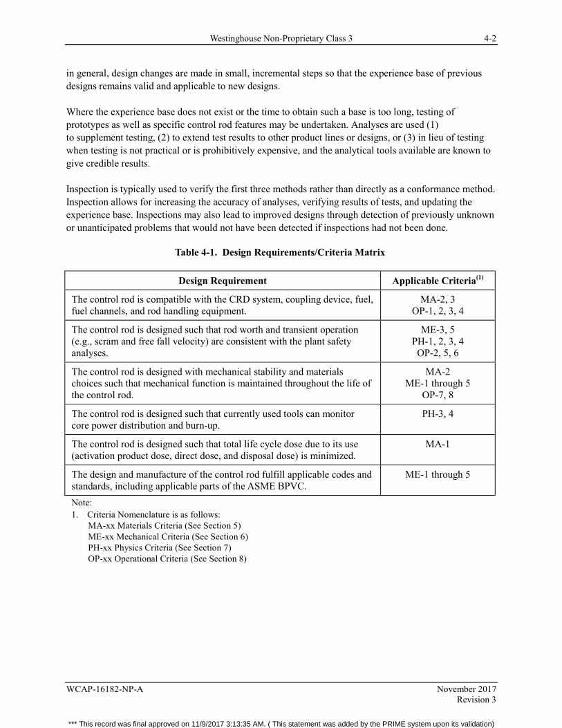
Westinghouse Non-Proprietary Class 3 4-2
WCAP-16182-NP-A November 2017 Revision 3
in general, design changes are made in small, incremental steps so that the experience base of previous designs remains valid and applicable to new designs.
Where the experience base does not exist or the time to obtain such a base is too long, testing of prototypes as well as specific control rod features may be undertaken. Analyses are used (1) to supplement testing, (2) to extend test results to other product lines or designs, or (3) in lieu of testing when testing is not practical or is prohibitively expensive, and the analytical tools available are known to give credible results.
Inspection is typically used to verify the first three methods rather than directly as a conformance method. Inspection allows for increasing the accuracy of analyses, verifying results of tests, and updating the experience base. Inspections may also lead to improved designs through detection of previously unknown or unanticipated problems that would not have been detected if inspections had not been done.
Table 4-1. Design Requirements/Criteria Matrix
Design Requirement Applicable Criteria(1)
The control rod is compatible with the CRD system, coupling device, fuel, fuel channels, and rod handling equipment.
MA-2, 3 OP-1, 2, 3, 4
The control rod is designed such that rod worth and transient operation (e.g., scram and free fall velocity) are consistent with the plant safety analyses.
ME-3, 5 PH-1, 2, 3, 4 OP-2, 5, 6
The control rod is designed with mechanical stability and materials choices such that mechanical function is maintained throughout the life of the control rod.
MA-2 ME-1 through 5
OP-7, 8
The control rod is designed such that currently used tools can monitor core power distribution and burn-up.
PH-3, 4
The control rod is designed such that total life cycle dose due to its use (activation product dose, direct dose, and disposal dose) is minimized.
MA-1
The design and manufacture of the control rod fulfill applicable codes and standards, including applicable parts of the ASME BPVC.
ME-1 through 5
Note: 1. Criteria Nomenclature is as follows:
MA-xx Materials Criteria (See Section 5) ME-xx Mechanical Criteria (See Section 6) PH-xx Physics Criteria (See Section 7) OP-xx Operational Criteria (See Section 8)
*** This record was final approved on 11/9/2017 3:13:35 AM. ( This statement was added by the PRIME system upon its validation)
Westinghouse Non-Proprietary Class 3 5-1
WCAP-16182-NP-A November 2017 Revision 3
5 MATERIALS EVALUATION
5.1 CRITICAL ATTRIBUTES
The critical attributes for materials related items are given in Table 5-1. The materials used in the CR 99 design are also included in the table.
5.2 CRITICAL ATTRIBUTES DISCUSSION
5.2.1 Rod Wing and Handle Material
Use of AISI 316L SS for the rod wing and handle is based on extensive in-reactor experience with the material. Better resistance to IASCC of AISI 316L SS has made it the preferred blade wing material (Reference 8). Since this material is in the reactor and subject to neutron activation, limits on cobalt concentration are set to minimize the release of cobalt to the primary coolant as well as minimize direct doses due to disposal.
5.2.2 Button and Roller Material
These components are subject to contact and are designed to slide or ride against other material. Thus the button and roller material must be wear resistant. Original equipment control rods in GE BWRs were made of material containing high cobalt concentrations (50% to 60%). While acceptable from the wear standpoint, they released unacceptable amounts of cobalt into the reactor coolant. An Electric Power Research Institute (EPRI) project identified a non-cobalt material, Alloy X-750, as an acceptable material for use in fabricating these components. This material has been the material of choice, with the specified limited cobalt content, for the CR 99 control rod. Extensive in-reactor experience, confirmed during post irradiation examinations, has shown this material to perform as required. During the last 20 years, AISI 316L SS has also been used in control rod buttons. Operational experience with this material is also very good.
Operational experience has also demonstrated that the control rods can be operated without a top button. No wear on any component, control rod or fuel channels, has been observed (Reference 13). Additionally, no wear has been observed after Reference 13 was issued.
5.2.3 Absorbing Materials
Extensive in-reactor experience with boron carbide (B4C) powder has been amassed on Westinghouse BWR control rods. In-pile measurements of helium gas pressure have confirmed the validity and conservatism of the helium release model used in the analyses.
With CR 99, Westinghouse has introduced [ ]a,c This can be compared to the highest density of powder, about 70%, or standard sintering density of about 73%.
*** This record was final approved on 11/9/2017 3:13:35 AM. ( This statement was added by the PRIME system upon its validation)
Westinghouse Non-Proprietary Class 3 5-2
WCAP-16182-NP-A November 2017 Revision 3
In a control rod with B4C powder, the powder densifies during operation and also swells due to neutron absorption reactions. Westinghouse experience is that the competing effects of powder densification and swelling can result in the swelling powder contacting the surrounding stainless steel, possibly causing IASCC.
[ ]a,c
Reference 14 is updated and superseded by Reference 33, which describes the outline of the CR 99 control rod for an S-Lattice BWR6 reactor. CR 99 control rods have accumulated significant operating experience in BWRs.
5.2.4 Velocity Limiter
The design of the velocity limiter is very important to the control rod drop accident analysis. The design of this important component is discussed in Section 8 of this report. From a materials standpoint, the velocity limiter must be made from a material which can be readily cast, machined to final dimensions, and attached to the rod wings. Since it is in contact with primary coolant, cobalt content must also be controlled. The velocity limiter for the CR 99 is manufactured from cast American Iron and Steel Institute (AISI) 304L SS.
Extensive in-reactor experience with all Westinghouse control rods has shown the acceptability of this material for the velocity limiter.
5.2.5 Coupling Socket
The design of the coupling socket is important for proper operation of the control rod. The design of this component is discussed in Section 8 of this report. The coupling socket must be made from a material which can be machined to final dimensions and has sufficient strength to keep the control rod coupled to the drive mechanism. The coupling socket is manufactured from Alloy X-750. Extensive in-reactor experience with this material has shown its acceptability for the coupling socket.
*** This record was final approved on 11/9/2017 3:13:35 AM. ( This statement was added by the PRIME system upon its validation)
Westinghouse Non-Proprietary Class 3 5-3
WCAP-16182-NP-A November 2017 Revision 3
5.3 MATERIALS CRITERIA AND DISCUSSION
The following criteria are shown in Table 5-2 along with the conformance method(s) required to confirm that the criteria are met. CR 99 evaluation results are also provided.
5.3.1 Materials Criterion 1 (MA-1)
Criterion
No material shall be used which results in a larger total rod lifetime dose (direct + indirect) than the material which it is to replace. If it does, compensatory measures must be implemented in some other material(s) to reduce total rod dose to meet this criterion.
Discussion
This criterion ensures that all Westinghouse control rod designs will have at least the same (relative to OEM rods) characteristics with respect to cobalt release during operation, dose received during replacement and preparation for disposal, and disposal-related radiological parameters (dose and curie content).
Evaluating the dose impact for a new material only involves a verification that it contains a lower quantity of radioactive components (e.g., cobalt) than the material that it is replacing. For less obvious material changes, the investigation may require the use of the Westinghouse computer model BKM-CRUD (Reference 15) to determine the impact.
5.3.2 Materials Criterion 2 (MA-2)
Criterion
Rod wing material shall be better than or equal to original blade wing material (Type 304L stainless steel) with respect to stress corrosion cracking, particularly susceptibility to fast neutron IASCC.
Discussion
This criterion and its conformance methods ensure that only materials superior to those already in use are used for rod wings. Thus, it is possible to use past in-reactor experience as a conservative experience base for the new material.
As shown in Table 5-2, the conformance method required to confirm that a material is superior is testing and experience. Previous in-reactor experience with the proposed material and/or testing (e.g., in-pile material tests, autoclave tests, lead control rods, etc.) provides confidence that a material is superior, but the ultimate proof is long term use in its final form in control rods in the reactor. For this reason, the lead control rods containing critical components with new material need to be inspected to confirm results of pre-use testing and adequacy of the experience base.
*** This record was final approved on 11/9/2017 3:13:35 AM. ( This statement was added by the PRIME system upon its validation)
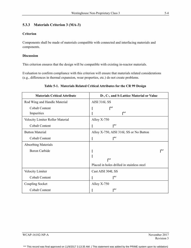
Westinghouse Non-Proprietary Class 3 5-4
WCAP-16182-NP-A November 2017 Revision 3
5.3.3 Materials Criterion 3 (MA-3)
Criterion
Components shall be made of materials compatible with connected and interfacing materials and components.
Discussion
This criterion ensures that the design will be compatible with existing in-reactor materials.
Evaluation to confirm compliance with this criterion will ensure that materials related considerations (e.g., differences in thermal expansion, wear properties, etc.) do not create problems.
Table 5-1. Materials Related Critical Attributes for the CR 99 Design
Materials Critical Attribute D-, C-, and S-Lattice Material or Value
Rod Wing and Handle Material AISI 316L SS
Cobalt Content Impurities
[ ]a,c [ ]a,c
Velocity Limiter Roller Material Alloy X-750
Cobalt Content [ ]a,c
Button Material Alloy X-750, AISI 316L SS or No Button
Cobalt Content [ ]a,c
Absorbing Materials
Boron Carbide [ ]a,c [ ]a,c Placed in holes drilled in stainless steel
Velocity Limiter Cast AISI 304L SS
Cobalt Content [ ]a,c
Coupling Socket Alloy X-750
Cobalt Content [ ]a,c
*** This record was final approved on 11/9/2017 3:13:35 AM. ( This statement was added by the PRIME system upon its validation)
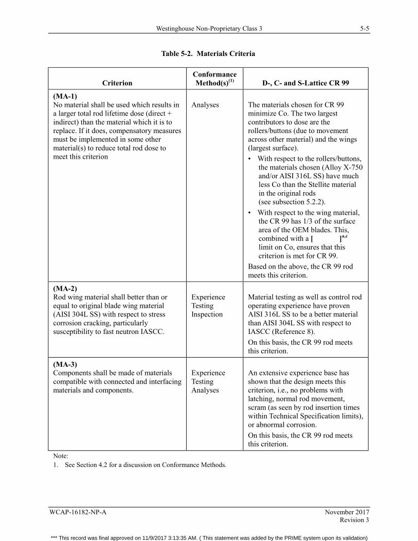
Westinghouse Non-Proprietary Class 3 5-5
WCAP-16182-NP-A November 2017 Revision 3
Table 5-2. Materials Criteria
Criterion Conformance Method(s)(1) D-, C- and S-Lattice CR 99
(MA-1) No material shall be used which results in a larger total rod lifetime dose (direct + indirect) than the material which it is to replace. If it does, compensatory measures must be implemented in some other material(s) to reduce total rod dose to meet this criterion
Analyses
The materials chosen for CR 99 minimize Co. The two largest contributors to dose are the rollers/buttons (due to movement across other material) and the wings (largest surface). • With respect to the rollers/buttons,
the materials chosen (Alloy X-750 and/or AISI 316L SS) have much less Co than the Stellite material in the original rods (see subsection 5.2.2).
• With respect to the wing material, the CR 99 has 1/3 of the surface area of the OEM blades. This, combined with a [ ]a,c limit on Co, ensures that this criterion is met for CR 99.
Based on the above, the CR 99 rod meets this criterion.
(MA-2) Rod wing material shall better than or equal to original blade wing material (AISI 304L SS) with respect to stress corrosion cracking, particularly susceptibility to fast neutron IASCC.
Experience Testing Inspection
Material testing as well as control rod operating experience have proven AISI 316L SS to be a better material than AISI 304L SS with respect to IASCC (Reference 8). On this basis, the CR 99 rod meets this criterion.
(MA-3) Components shall be made of materials compatible with connected and interfacing materials and components.
Experience Testing Analyses
An extensive experience base has shown that the design meets this criterion, i.e., no problems with latching, normal rod movement, scram (as seen by rod insertion times within Technical Specification limits), or abnormal corrosion. On this basis, the CR 99 rod meets this criterion.
Note: 1. See Section 4.2 for a discussion on Conformance Methods.
*** This record was final approved on 11/9/2017 3:13:35 AM. ( This statement was added by the PRIME system upon its validation)
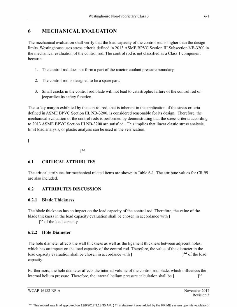
Westinghouse Non-Proprietary Class 3 6-1
WCAP-16182-NP-A November 2017 Revision 3
6 MECHANICAL EVALUATION
The mechanical evaluation shall verify that the load capacity of the control rod is higher than the design limits. Westinghouse uses stress criteria defined in 2013 ASME BPVC Section III Subsection NB-3200 in the mechanical evaluation of the control rod. The control rod is not classified as a Class 1 component because:
1. The control rod does not form a part of the reactor coolant pressure boundary.
2. The control rod is designed to be a spare part.
3. Small cracks in the control rod blade will not lead to catastrophic failure of the control rod or jeopardize its safety function.
The safety margin exhibited by the control rod, that is inherent in the application of the stress criteria defined in ASME BPVC Section III, NB-3200, is considered reasonable for its design. Therefore, the mechanical evaluation of the control rods is performed by demonstrating that the stress criteria according to 2013 ASME BPVC Section III NB-3200 are satisfied. This implies that linear elastic stress analysis, limit load analysis, or plastic analysis can be used in the verification.
[ ]a,c
6.1 CRITICAL ATTRIBUTES
The critical attributes for mechanical related items are shown in Table 6-1. The attribute values for CR 99 are also included.
6.2 ATTRIBUTES DISCUSSION
6.2.1 Blade Thickness
The blade thickness has an impact on the load capacity of the control rod. Therefore, the value of the blade thickness in the load capacity evaluation shall be chosen in accordance with [ ]a,c of the load capacity.
6.2.2 Hole Diameter
The hole diameter affects the wall thickness as well as the ligament thickness between adjacent holes, which has an impact on the load capacity of the control rod. Therefore, the value of the diameter in the load capacity evaluation shall be chosen in accordance with [ ]a,c of the load capacity.
Furthermore, the hole diameter affects the internal volume of the control rod blade, which influences the internal helium pressure. Therefore, the internal helium pressure calculation shall be [ ]a,c
*** This record was final approved on 11/9/2017 3:13:35 AM. ( This statement was added by the PRIME system upon its validation)
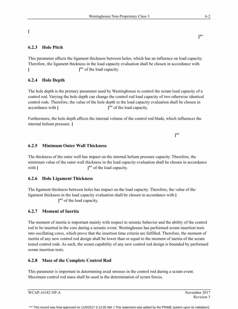
Westinghouse Non-Proprietary Class 3 6-2
WCAP-16182-NP-A November 2017 Revision 3
[ ]a,c
6.2.3 Hole Pitch
This parameter affects the ligament thickness between holes, which has an influence on load capacity. Therefore, the ligament thickness in the load capacity evaluation shall be chosen in accordance with [ ]a,c of the load capacity.
6.2.4 Hole Depth
The hole depth is the primary parameter used by Westinghouse to control the scram load capacity of a control rod. Varying the hole depth can change the control rod load capacity of two otherwise identical control rods. Therefore, the value of the hole depth in the load capacity evaluation shall be chosen in accordance with [ ]a,c of the load capacity.
Furthermore, the hole depth affects the internal volume of the control rod blade, which influences the internal helium pressure. [ ]a,c
6.2.5 Minimum Outer Wall Thickness
The thickness of the outer wall has impact on the internal helium pressure capacity. Therefore, the minimum value of the outer wall thickness in the load capacity evaluation shall be chosen in accordance with [ ]a,c of the load capacity.
6.2.6 Hole Ligament Thickness
The ligament thickness between holes has impact on the load capacity. Therefore, the value of the ligament thickness in the load capacity evaluation shall be chosen in accordance with [ ]a,c of the load capacity.
6.2.7 Moment of Inertia
The moment of inertia is important mainly with respect to seismic behavior and the ability of the control rod to be inserted in the core during a seismic event. Westinghouse has performed scram insertion tests into oscillating cores, which prove that the insertion time criteria are fulfilled. Therefore, the moment of inertia of any new control rod design shall be lower than or equal to the moment of inertia of the scram tested control rods. As such, the scram capability of any new control rod design is bounded by performed scram insertion tests.
6.2.8 Mass of the Complete Control Rod
This parameter is important in determining axial stresses in the control rod during a scram event. Maximum control rod mass shall be used in the determination of scram forces.
*** This record was final approved on 11/9/2017 3:13:35 AM. ( This statement was added by the PRIME system upon its validation)
Westinghouse Non-Proprietary Class 3 6-3
WCAP-16182-NP-A November 2017 Revision 3
6.2.9 Mass of the Control Rod Without the Velocity Limiter and Socket
This parameter is important in determining axial stresses in the control rod during a scram event. Maximum control rod mass, without the velocity limiter and socket, shall be used in the determination of scram forces.
6.2.10 Control Rod Design Temperature
The control rod temperature is set by the design temperature of the plant reactor coolant system. This value is far below any value that could substantially degrade (melt) the material in the control rod.
6.2.11 Control Rod Design Pressure
The control rod design pressure is set by the design of the core (axial depletion profile of the control rod) and plant reactor coolant system. The control rod design pressure is used in the calculation of the stresses across the hole walls due to differential pressure.
6.2.12 Handle Design
Westinghouse has manufactured control rods with both single and double handles. The safety function of the control rods does not depend on the handle design. However, the designs must be: (1) checked for compatibility with the rod handling equipment, and (2) evaluated to ensure that the handle will be able to take the stresses due to normal loading and handling. Note that item (1) is addressed in Section 8, Operational Evaluation.
In general, the original control rods for D-Lattice plants were built with single handles, C-Lattice plants have a mix of single and double handle control rods, and S-Lattice plants have double handle control rods.
6.2.13 Welds
The weld quality factor and fatigue strength reduction factor according to 2013 ASME BPVC Section III Table NG-3352-1 shall apply in the structural verification of welds.
6.3 MATERIALS STRENGTH PROPERTIES
The material strength properties to be used in the stress (load capacity) evaluation shall be at least [ ]a,c If tensile test data allowing the statistical evaluation of material strength properties does not exist, strength data from Westinghouse material specifications or 2013 ASME BPVC Section II Part D shall be used.
Mechanical stress/strain data for material in irradiated conditions is provided in References 40, 41, and 43.
*** This record was final approved on 11/9/2017 3:13:35 AM. ( This statement was added by the PRIME system upon its validation)
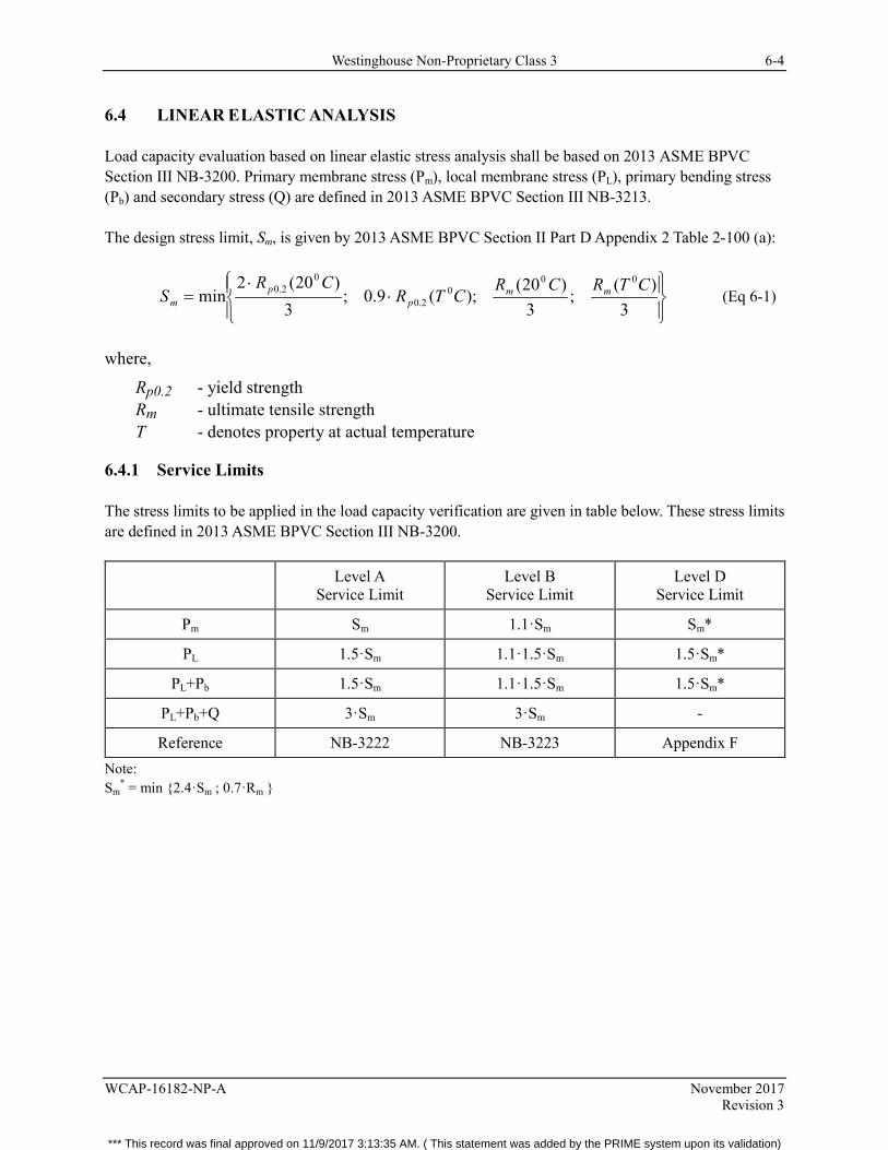
Westinghouse Non-Proprietary Class 3 6-4
WCAP-16182-NP-A November 2017 Revision 3
6.4 LINEAR ELASTIC ANALYSIS
Load capacity evaluation based on linear elastic stress analysis shall be based on 2013 ASME BPVC Section III NB-3200. Primary membrane stress (Pm), local membrane stress (PL), primary bending stress (Pb) and secondary stress (Q) are defined in 2013 ASME BPVC Section III NB-3213.
The design stress limit, Sm, is given by 2013 ASME BPVC Section II Part D Appendix 2 Table 2-100 (a):
⋅⋅
=3
)(;
3)20(
);(9.0;3
)20(2min
000
2.0
02.0 CTRCR
CTRCR
S mmp
pm (Eq 6-1)
where,
Rp0.2 - yield strength Rm - ultimate tensile strength T - denotes property at actual temperature
6.4.1 Service Limits
The stress limits to be applied in the load capacity verification are given in table below. These stress limits are defined in 2013 ASME BPVC Section III NB-3200.
Level A Service Limit
Level B Service Limit
Level D Service Limit
Pm Sm 1.1·Sm Sm*
PL 1.5·Sm 1.1·1.5·Sm 1.5·Sm*
PL+Pb 1.5·Sm 1.1·1.5·Sm 1.5·Sm*
PL+Pb+Q 3·Sm 3·Sm -
Reference NB-3222 NB-3223 Appendix F Note: Sm
* = min {2.4·Sm ; 0.7·Rm }
*** This record was final approved on 11/9/2017 3:13:35 AM. ( This statement was added by the PRIME system upon its validation)
Westinghouse Non-Proprietary Class 3 6-5
WCAP-16182-NP-A November 2017 Revision 3
6.5 LIMIT LOAD ANALYSIS
The limit load analysis is a plastic analysis that uses the definition of an ideal plastic material. According to the lower bound theorem, 2013 ASME BPVC Section III NB-3213.29, a collapse load is defined as any system of stresses that satisfy equilibrium. In practice, this implies that any force converge solution in a plastic finite element analysis that is based on the definition of an ideal plastic material, is a conservative estimation of the lower bound collapse load.
6.5.1 Level A Service Limit
Load capacity for Level A service limit shall be based on a yield strength equal 1.5·Sm , 2013 ASME BPVC Section III NB-3228.1. The allowed load is defined to 2/3 of calculated lower bound collapse load.
6.5.2 Level B Service Limit
Load capacity for Level B service limit shall be based on a yield strength equal 1.5·Sm , 2013 ASME BPVC Section III NB-3228.1. The allowed load shall be calculated as 1.1x2/3 of calculated lower bound collapse load. The use of the 1.1 factor is the Westinghouse interpretation of the increase in allowable stress intensity defined in 2013 ASME BPVC Section III NB-3223, and is applied for the allowable load capacity. 6.5.3 Level D Service Limit
Load capacity for Level D service limit shall be based on yield strength equal;
{ }mp RSmR ⋅⋅= 7.0,3.2min2.0 (Eq 6-2)
Allowed load shall be calculated as 90% of calculated lower bound collapse load, 2013 ASME BPVC Section III Appendix F-1341.3.
6.5.4 Shake Down and Cyclic Response
Shake down analysis shall be performed based on 2013 ASME BPVC Section III NB-3228.4. The design of the control rod shall be considered acceptable if shake down occurs.
The cyclic response to be used in fatigue assessment shall be calculated as the numerically maximum principal total strain range multiplied by one-half of the modulus of elasticity of the material at the mean value of the temperature of the cycle, 2013 ASME BPVC Section III NB-3228.4 (c).
The Westinghouse interpretation of the fatigue assessment is that it shall be based on the cyclic response. If shake down occurs during the initial load cycles, these load cycles shall be neglected in the fatigue assessment and the stable cyclic response of the structure will be used instead. If stable cyclic response does not evolve, each load cycle shall be evaluated and the linear damage summation shall be used to calculate the cumulative damage due to the cyclic response.
*** This record was final approved on 11/9/2017 3:13:35 AM. ( This statement was added by the PRIME system upon its validation)
Westinghouse Non-Proprietary Class 3 6-6
WCAP-16182-NP-A November 2017 Revision 3
6.6 MECHANICAL CRITERIA AND DISCUSSION
Mechanical design criteria to be met are stress limits (load capacity limits) and fatigue limits for conditions under which the control rod will be operating during its lifetime. Criteria to be used in the stress (load capacity) evaluation are defined in Section 6.4 (linear elastic stress analysis) or in Section 6.5 (limit load analysis).
The loads that the control rods will be subjected to during their lifetime originate from transport and handling, pressure differences between the inside and the outside of the control rod blade wing, scram loads, and loads due to interaction with fuel channels during sever core vibrations. Mechanical Criterion 1 in subsection 6.6.1 through Mechanical Criterion 5 in subsection 6.6.5 specify the loads that a control rod shall be able to withstand without exceeding the limits identified in 6.4.1. Subsection 6.6.3.2 specifies the load history to be used in fatigue assessment of the control rods, the methods used to perform the fatigue assessment, and the design criteria to be satisfied.
6.6.1 Mechanical Criterion 1 (ME-1)
Criterion
Stresses (or loads) on the control rod handle due to normal loading and handling shall not exceed the allowable values for Level A Service Condition any time during the life of the control rod.
Discussion
This criterion ensures that a control rod can be safely moved during receipt, initial installation, shuffling, removal, and preparation for disposal.
In the Westinghouse design, the support and the handle have been integrated with the control rod wings, which means that there is only one vertical weld where the two control rod wings are joined in the lifting handle.
During normal handling operations, the lifting handle is loaded with the weight of the control rod in air. In stress analysis (load capacity analysis), this load is conservatively chosen as a concentrated force at the weld location on the horizontal portion of the handle. The force to be applied on the handle is:
gMF CRlift ⋅⋅= 2 (Eq 6-3)
where,
2 – is the dynamic lifting factor MCR – is the mass of the control rod g – is the standard gravity.
*** This record was final approved on 11/9/2017 3:13:35 AM. ( This statement was added by the PRIME system upon its validation)
Westinghouse Non-Proprietary Class 3 6-7
WCAP-16182-NP-A November 2017 Revision 3
6.6.2 Mechanical Criterion 2 (ME-2)
Criterion
Stresses (or loads) in the control rod wings due to pressure differential shall not exceed the allowable values for the Level A Service Condition anytime during the life of the control rod.
Discussion
This criterion ensures that allowable stress limits (load limits) are met with the maximum outside to inside ΔP at the beginning of life and maximum inside to outside ΔP at the end of life, and at all differential pressures in between that a Westinghouse control rod may be subjected to during its lifetime.
6.6.2.1 Pressure Difference Determination
During reactor operation the gas pressure in the control rod blades increases with 10B depletion. From the initial filling gap pressure the differential pressure, ΔP, gradually increases to its maximum design pressure across the wall of the blades at Mechanical End of Life (MEOL). The differential pressure for which the blade stresses must be calculated is also a function of reactor temperature and system pressure.
[
]a,c
*** This record was final approved on 11/9/2017 3:13:35 AM. ( This statement was added by the PRIME system upon its validation)
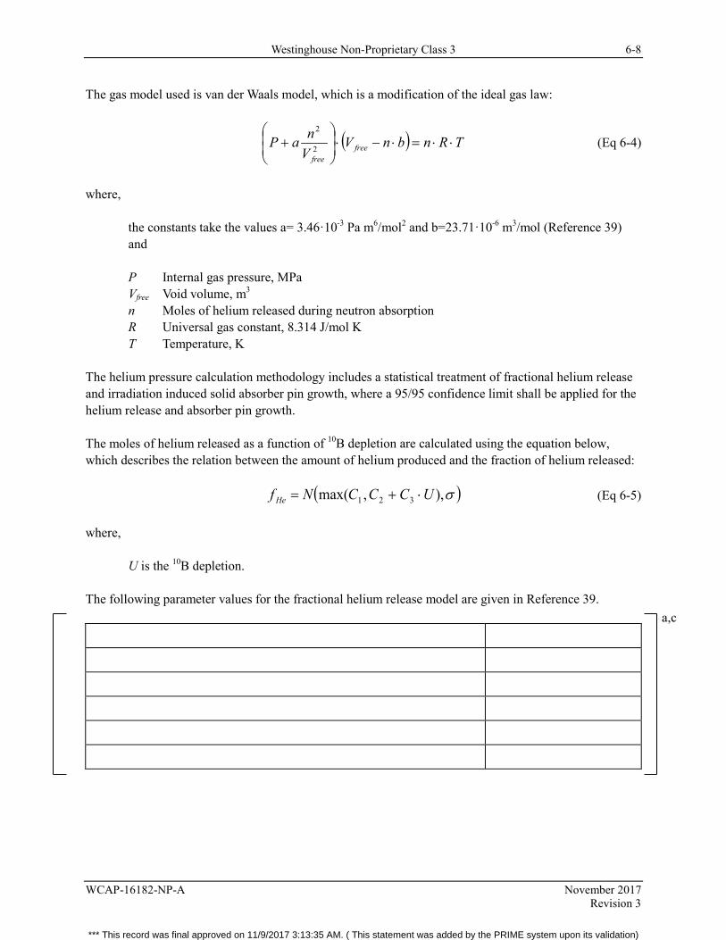
Westinghouse Non-Proprietary Class 3 6-8
WCAP-16182-NP-A November 2017 Revision 3
The gas model used is van der Waals model, which is a modification of the ideal gas law:
( ) TRnbnVVnaP free
free
⋅⋅=⋅−⋅
+ 2
2
(Eq 6-4)
where,
the constants take the values a= 3.46·10-3 Pa m6/mol2 and b=23.71·10-6 m3/mol (Reference 39) and
P Internal gas pressure, MPa Vfree Void volume, m3 n Moles of helium released during neutron absorption R Universal gas constant, 8.314 J/mol K T Temperature, K
The helium pressure calculation methodology includes a statistical treatment of fractional helium release and irradiation induced solid absorber pin growth, where a 95/95 confidence limit shall be applied for the helium release and absorber pin growth.
The moles of helium released as a function of 10B depletion are calculated using the equation below, which describes the relation between the amount of helium produced and the fraction of helium released:
( )σ),,max( 321 UCCCNf He ⋅+= (Eq 6-5)
where,
U is the 10B depletion.
The following parameter values for the fractional helium release model are given in Reference 39.
a,c
*** This record was final approved on 11/9/2017 3:13:35 AM. ( This statement was added by the PRIME system upon its validation)
Westinghouse Non-Proprietary Class 3 6-9
WCAP-16182-NP-A November 2017 Revision 3
[
]a,c
*** This record was final approved on 11/9/2017 3:13:35 AM. ( This statement was added by the PRIME system upon its validation)
Westinghouse Non-Proprietary Class 3 6-10
WCAP-16182-NP-A November 2017 Revision 3
[ ]a,c
6.6.3 Mechanical Criterion 3 (ME-3)
Criterion
Stresses (or loads) in the control rod due to scram loads, assuming normal operation of the scram equipment, shall not exceed allowable values defined in subsection 6.4.1 (or section 6.5.1) for Level A Service Condition anytime in life. Stresses (or loads) in the control rod due to scram loads, assuming a failed buffer, shall not exceed allowable values defined in subsection 6.4.1 (or subsection 6.5.2) for Level B Service Condition anytime in life.
Furthermore, fatigue damage in a control rod shall not evolve during the designed lifetime. The lifetime of a control rod is defined at 200 start/stop cycles of the reactor and each start/stop cycle shall include one scram event at cold conditions assuming a failed buffer, and two scram events at warm conditions assuming normal operation of the buffer.
Discussion
These criteria ensure that allowable stress limits (load limits) are met with any plant specific scram load definition throughout the lifetime of any Westinghouse control rod design.
6.6.3.1 Scram Load Definition
During a reactor scram, the control rods are hydraulically inserted into the reactor core and hydro-dynamically slowed down at the end of the stroke. Therefore, a scram load cycle is defined as a compressive scram force (acceleration) followed by a tensile scram force (deceleration). The maximum axial force in the control rod occurs during the deceleration phase at cold reactor conditions, and assuming a failed buffer. A scram during cold conditions (cold scram) is modeled at a temperature of 85°C and at 300°C in case of a scram during normal reactor operation (warm scram).
a,c
*** This record was final approved on 11/9/2017 3:13:35 AM. ( This statement was added by the PRIME system upon its validation)
Westinghouse Non-Proprietary Class 3 6-11
WCAP-16182-NP-A November 2017 Revision 3
6.6.3.2 Cyclic Load Combination
This criterion ensures that a control rod will not be damaged by fatigue during its lifetime, which is defined by the NEOL. [ ]a,c
Figure 6-1. Sketch Showing Load History (EOL) to be used in Fatigue Assessment
Fatigue assessment shall be based on fresh material fatigue data according to 2013 ASME BPVC Section II Part D. Linear summation of the calculated damage shall be used to prove that the sum, in the equation below, is always less than 1.0:
∑ <=i if
i
NN
D 1,
(Eq 6-11)
where,
Ni is the number of cycles and Nf,i is the corresponding number of cycles causing fatigue damage according to 2013 ASME BPVC Section II Part D.
a,c
*** This record was final approved on 11/9/2017 3:13:35 AM. ( This statement was added by the PRIME system upon its validation)
Westinghouse Non-Proprietary Class 3 6-12
WCAP-16182-NP-A November 2017 Revision 3
6.6.4 Mechanical Criterion 4 (ME-4)
Criterion
Swelling of the B4C pins should not cause cracking in the blades.
Discussion
This criterion is set as a design goal.
A consequence of neutron absorption is that the absorber pins swell due to the reaction:
10B + n 7Li + 4He + 2.8 MeV
[
]a,c
6.6.4.1 Pin Swelling Loads
Absorber pins swell as a consequence of the neutron flux, therefore, maximum pin swelling load occurs at the position of maximum fluence and at NEOL.
The load acting on the control rod at the position of maximum fluence originates from a combination of helium pressure, scram load, and absorber pin swelling. Pin swelling shall be included in the finite element model as a volumetric swelling of the absorber pin and its properties shall be based on the models documented in Reference 36.
Primary stresses (or loads) in the control rod blades shall fulfill the criteria for the Level A Service Limit (identified in Section 6.4.1) for a normal scram, including the effects of loads due to pin swelling and helium pressure. The long term behavior of the control rod blade shall be evaluated based on the IASCC prediction model that is under development, as described in section 6.6.4.
*** This record was final approved on 11/9/2017 3:13:35 AM. ( This statement was added by the PRIME system upon its validation)
Westinghouse Non-Proprietary Class 3 6-13
WCAP-16182-NP-A November 2017 Revision 3
[ ]a,c
The structural verification includes the irradiation hardening of the control rod blade material at NEOL.
6.6.4.2 Pin Swelling Load Combined with Scram Force and Helium Pressure
Pin swelling load, combined with scram force, and helium pressure has been analyzed. These analyses show that the CR 99 design has sufficient load capacity to withstand such combined loads, per References 40 and 41. Mechanical properties of the absorber pins have been determined by the theoretical modelling shown in Reference 42.
6.6.5 Mechanical Criterion 5 (ME-5)
Criterion
Insertion of the control rod into an oscillating reactor core during a dynamic event shall not influence the control rod worth nor its future operation. The future operation depends on the frequency classification of the dynamic event (Anticipated Operational Occurrence or Accident).
Insertion time shall be less than minimum specified insertion time for the reactor type of consideration.
Discussion
This criterion ensures that the control rods have the capability to shut down the reactor core within the specified time frame and that the reactor core remains in the shutdown condition. The criterion also means that the neutron absorbing B4C must remain in the design position during control rod insertion and when the control rod is positioned in the core.
The flexibility of the control rod is described by the moment of inertia (MOI). Lower MOI means a more flexible control rod that is easier to insert into the core. Furthermore, a lower MOI also decreases contact forces (frictional forces) between the control rod and its neighboring channels. Westinghouse uses a test rig to simulate control rods being inserted into an oscillating core in order to measure insertion times for specific core designs (lattice type). The insertion time requirement for any control rod design with an equal or lower MOI is verified by tests. Acceptable insertion times for the Westinghouse CR 85 control rod designs for BWR2/3/4, BWR 5, and BWR 6 corresponding to the D-, C-, and S-Lattice [ ]a,c are verified in Toshiba laboratory tests under simulated earthquake conditions. The tests verified the insertion times for the Westinghouse CR 85 for vibration amplitudes up to [ ]a,c Test results are shown in Reference 23. Since the MOI for the CR 99 is equal or less than that for the CR 85, see Table 6-1, the CR 99 design can be considered bound by the tests on the CR 85.
*** This record was final approved on 11/9/2017 3:13:35 AM. ( This statement was added by the PRIME system upon its validation)
Westinghouse Non-Proprietary Class 3 6-14
WCAP-16182-NP-A November 2017 Revision 3
The impact of seismic events up to [ ]a,c fuel channel deflection has been studied for both D-/S-lattice, as well as the C-lattice CR 99. Cyclic plastic analyses and fatigue assessments show that no cracking will be initiated due to seismic events up to this magnitude. However, pin swelling loads have not been included in these analyses for two reasons. Firstly, at BOL the diameter of the B4C pins is smaller than the diameter of the absorber holes and, therefore, no contact forces are expected to evolve during core oscillations. Secondly, by EOL the solid B4C pins would have been transformed into powder, which would compress during the first core oscillation and result in an insignificant swelling force.
In the last few years, channel distortion has been an increasing challenge for BWR plants. The causes of channel distortion include the fast neutron flux gradient across the channel (both axially and radially) and the proximity of a CRBs near the channel. Even with channel distortion, a CRB can be inserted in the core during a scram because the forces driving the blade into the core are significantly higher than the friction forces between the channel and CRB. However, since these friction forces can lengthen the time it takes for the scram to be completed, it can affect the assumptions in the accident analysis. For that reason, the plant closely monitors for the presence of channel distortion. Calculational analyses and periodic scram tests are performed to ensure that no excessive force is needed to insert the CRBs into the core. If the force needed to insert a CRB exceeds a certain conservative level during a scram test, then that blade is completely inserted in the core and declared inoperable for the rest of the cycle.
Stress verification of the control rod when scrammed into an oscillating core has been done by plastic analysis with acceptance criteria according to ASME III Appendix F (Reference 44). Assumptions for the loads applied in the analyses are:
• Constant control rod temperature of 300 oC. • Loads from absorber pin swelling shall be included based on section 6.6.4.1.
o BOL, zero swelling forces o EOL, maximum quarter segment 10B depletion shall be used to determine the loads from
absorber pin swelling • Helium pressure
o BOL, helium pressure ( )( ) fillhelium PP ⋅
++
=27320273300
where Pfill is helium fill pressure after
manufacturing. o EOL, helium pressure EOL shall be applied
• Maximum core oscillation of [ ]a,c shall be assumed in the analysis • Scram force shall be included in the analyses assuming normal operation of buffer.
The forces are linearly ramped up as a function of analysis time until collapse of the structure occurs or until sufficient safety margin can be demonstrated. Zero load is assumed at analysis time zero. Loads increase as illustrated in the figures described below. Figure 6-10 shows the finite element (FE) model used in the analysis of the S- & D-Lattice designs and the deformation caused by the core oscillation. Figures 6-11 and 6-12 shows loads applied in the EOL analysis of the S- & D-Lattice designs.
*** This record was final approved on 11/9/2017 3:13:35 AM. ( This statement was added by the PRIME system upon its validation)
Westinghouse Non-Proprietary Class 3 6-15
WCAP-16182-NP-A November 2017 Revision 3
The model includes a high resolution of details close to the most highly stressed section in the control rod. At other locations the model is simplified with less resolution. BOL analysis is based on fresh material data for the stainless steel and the EOL analysis is based on irradiated material data.
The results presented in Figures 6-13 and 6-14 show that collapse of the CR occurs at loads higher than 1.5 times the loadings specified in Reference 44. The control rod is therefore verified for the specified loads with a margin of at least 50%.
Structural verification of the S- & D-Lattice designs, Reference 40, compared with structural verification of the C-Lattice design shows that the utilization of the C-Lattice design is lower for scram loads, helium pressure loads and absorber pin swelling loads. Furthermore, the geometry of the C-Lattice design is more beneficial with respect to loads originating from absorber pin swelling (smaller diameter of absorber pins and the same wall thickness). Therefore, the seismic analyses of the S- & D-Lattice designs bound the C- Lattice design.
*** This record was final approved on 11/9/2017 3:13:35 AM. ( This statement was added by the PRIME system upon its validation)

Westinghouse Non-Proprietary Class 3 6-16
WCAP-16182-NP-A November 2017 Revision 3
Table 6-1. Mechanical Critical Attributes for CR 99 Designs
Mechanical Critical Attribute
Hole diameter
Hole pitch
Hole depth
Minimum outer wall thickness
Hole ligament thickness
Non-irradiated HIP pin maximum diameter (dp)
Moment of inertia
Mass of complete control rod (m)
Mass of control rod without the velocity limiter and socket (m1)
Control rod design temperature
Control rod design pressure (Py, reactor operation)
Control rod design pressure, Pi (ΔP= Pi-Py for Stress Calculations)
Handle design
a,c
*** This record was final approved on 11/9/2017 3:13:35 AM. ( This statement was added by the PRIME system upon its validation)

Westinghouse Non-Proprietary Class 3 6-17
WCAP-16182-NP-A November 2017 Revision 3
Table 6-2. Mechanical Criteria
Criterion Conformance
Method(s) D-Lattice Reference 40 C-Lattice Reference 41 S-Lattice Reference 40
a,c
*** This record was final approved on 11/9/2017 3:13:35 AM. ( This statement was added by the PRIME system upon its validation)
Westinghouse Non-Proprietary Class 3 6-18
WCAP-16182-NP-A November 2017 Revision 3
Table 6–2. Mechanical Criteria (cont.)
a,c
*** This record was final approved on 11/9/2017 3:13:35 AM. ( This statement was added by the PRIME system upon its validation)
Westinghouse Non-Proprietary Class 3 6-19
WCAP-16182-NP-A November 2017 Revision 3
Figure 6-2. FEM Model of Handle
a,c
*** This record was final approved on 11/9/2017 3:13:35 AM. ( This statement was added by the PRIME system upon its validation)
Westinghouse Non-Proprietary Class 3 6-20
WCAP-16182-NP-A November 2017 Revision 3
Figure 6-3. Helium Release vs 10B-Depletion
a,c
*** This record was final approved on 11/9/2017 3:13:35 AM. ( This statement was added by the PRIME system upon its validation)
Westinghouse Non-Proprietary Class 3 6-21
WCAP-16182-NP-A November 2017 Revision 3
Figure 6-4. Design Pressure Curve
a,c
*** This record was final approved on 11/9/2017 3:13:35 AM. ( This statement was added by the PRIME system upon its validation)

Westinghouse Non-Proprietary Class 3 6-22
WCAP-16182-NP-A November 2017 Revision 3
Figure 6-5. Model of the Blade Wing Structure
a,c
*** This record was final approved on 11/9/2017 3:13:35 AM. ( This statement was added by the PRIME system upon its validation)
Westinghouse Non-Proprietary Class 3 6-23
WCAP-16182-NP-A November 2017 Revision 3
Figure not used
Figure 6-6. Not Used
*** This record was final approved on 11/9/2017 3:13:35 AM. ( This statement was added by the PRIME system upon its validation)
Westinghouse Non-Proprietary Class 3 6-24
WCAP-16182-NP-A November 2017 Revision 3
Figure 6-7. Seismic Scram Insertion Test, D-Lattice
a,b,c
*** This record was final approved on 11/9/2017 3:13:35 AM. ( This statement was added by the PRIME system upon its validation)
Westinghouse Non-Proprietary Class 3 6-25
WCAP-16182-NP-A November 2017 Revision 3
Figure 6-8. Seismic Scram Insertion Test, C-Lattice
a,b,c
*** This record was final approved on 11/9/2017 3:13:35 AM. ( This statement was added by the PRIME system upon its validation)
Westinghouse Non-Proprietary Class 3 6-26
WCAP-16182-NP-A November 2017 Revision 3
Figure 6-9. Seismic Scram Insertion Test, S-Lattice
a,b,c
*** This record was final approved on 11/9/2017 3:13:35 AM. ( This statement was added by the PRIME system upon its validation)
Westinghouse Non-Proprietary Class 3 6-27
WCAP-16182-NP-A November 2017 Revision 3
Figure 6-10. FE-Model Used to Analyze Seismic Loads on Control Rod
a,c
*** This record was final approved on 11/9/2017 3:13:35 AM. ( This statement was added by the PRIME system upon its validation)
Westinghouse Non-Proprietary Class 3 6-28
WCAP-16182-NP-A November 2017 Revision 3
Figure 6-11. Loads Applied in EOL Seismic Analysis of Control Rod.
a,c
*** This record was final approved on 11/9/2017 3:13:35 AM. ( This statement was added by the PRIME system upon its validation)
Westinghouse Non-Proprietary Class 3 6-29
WCAP-16182-NP-A November 2017 Revision 3
Figure 6-12. Radial 10B-Depletion Profile to Determine Absorber Pin Swelling Loads
a,c
*** This record was final approved on 11/9/2017 3:13:35 AM. ( This statement was added by the PRIME system upon its validation)
Westinghouse Non-Proprietary Class 3 6-30
WCAP-16182-NP-A November 2017 Revision 3
Figure 6-13. Results Showing No Collapse at BOL
a,c
*** This record was final approved on 11/9/2017 3:13:35 AM. ( This statement was added by the PRIME system upon its validation)
Westinghouse Non-Proprietary Class 3 6-31
WCAP-16182-NP-A November 2017 Revision 3
Figure 6-14. Results Showing No Collapse at EOL
a,c
*** This record was final approved on 11/9/2017 3:13:35 AM. ( This statement was added by the PRIME system upon its validation)
Westinghouse Non-Proprietary Class 3 7-1
WCAP-16182-NP-A November 2017 Revision 3
7 PHYSICS EVALUTION
7.1 CRITICAL ATTRIBUTES
The critical attributes for physics related items are given in Table 7-1. The values for the CR 99 control rod are also included in the table.
7.2 ATTRIBUTES DISCUSSION
7.2.1 Total Rod Worth
Rod worth calculations have been typically done using the PHOENIX code (Reference 26) to allow comparison of Westinghouse control rod worth to the worth of the rod it is replacing at various conditions simulating a range of reactor conditions. Results of these calculations are then used to confirm nuclear compatibility with the core.
PHOENIX single bundle calculations are made at three different conditions simulating various shutdown conditions:
1. Cold, clean critical – corresponding to the limiting shutdown condition, 2. Hot-Full power, zero void – corresponding to a location near the core inlet, and 3. Hot-Full power, 50% void – corresponding to the top of the core.
[ ]a,c
For multiple absorber control rods, the calculations are done for each different absorber zone separately. The total control rod worth difference between the Westinghouse control rod and the replaced rod is then a weighted sum of the various zones. The weighting factors describe the axial power distributions and depend on the type of control rod and on the shutdown conditions, cold clean or hot.
The differences between Westinghouse control rods and the replaced rod using the above procedure vary only slightly for any lattice type control rod design as a function of fuel burn-up and fuel type.
*** This record was final approved on 11/9/2017 3:13:35 AM. ( This statement was added by the PRIME system upon its validation)

Westinghouse Non-Proprietary Class 3 7-2
WCAP-16182-NP-A November 2017 Revision 3
7.2.2 Shutdown Margin (SDM)
In general, shutdown margin follows rod worth, i.e., higher worth translates to more shutdown margin. Westinghouse experience has shown the following to be a good estimate of the impact rod worth has on shutdown margin at limiting cold conditions:
[ ]a,c (Eq 7-1)
where,
∆ SDM is the change in SDM, relative to an OEM rod ∆ kCOLD is the PHOENIX single bundle cold clean rod worth of the OEM rod
( )%k
kkk CRwithout
CRwithoutCRwith
∞
∞∞ −=∆ (Eq 7-2)
and RWD is the relative rod worth difference between the Westinghouse control rod and the rod it is replacing
(%)100)OEM(k
)OEM(k)West(kRWD ⋅∆
∆−∆= (Eq 7-3)
[ ]a,c
For multiple absorber control rods, total SDM is a weighted sum of the various zones. [ ]a,c For an example of a CR 99 absorber material outline, see Reference 33. The total SDM change would be (Reference 35):
[
]a,c
As with the calculation of total rod worth, there is only a slight ∆SDM dependence on fuel burn-up and fuel type.
*** This record was final approved on 11/9/2017 3:13:35 AM. ( This statement was added by the PRIME system upon its validation)
Westinghouse Non-Proprietary Class 3 7-3
WCAP-16182-NP-A November 2017 Revision 3
7.2.3 LPRM Detector Signal Change
This calculation, which indicates the power distribution effect relative to the replaced rod, is also done using the PHOENIX code. Results of this calculation are used to ensure nuclear compatibility and negligible effect on the core monitoring system.
7.2.4 Nuclear End of Life
Many of the reload analyses performed, and core monitoring codes used in plants, assume that all control rods are new, full strength OEM control rods. For this assumption to remain valid for replacement rods, differences in replacement rod initial worth and allowable depletion relative to the OEM rods must be limited. Replacement rod initial worth of 95% to 105% of OEM initial worth, and allowable control rod depletion of 10% loss in reactivity from initial OEM rod worth, have been the historical limits for GE BWRs. Calculation of Westinghouse BWR control rod worth reduction is done using the PHOENIX/XYBDRY method described in Reference 27.
An important mechanical design characteristic of the CR 99 is [ ]a,c
References 28-30, updated and supplemented by new References 35-37, show calculated NEOLs for Westinghouse BWR CR 99 control rods based on the defined limit of 10% loss in reactivity from initial OEM rods.
7.3 PHYSICS CRITERIA AND DISCUSSION
The following criteria are shown in Table 7-2 along with the conformance method(s) required to confirm that the criteria are met. CR 99 evaluation results are also shown.
7.3.1 Physics Criterion 1 (PH-1)
Criterion
Total Westinghouse control rod initial worth shall be within [ ]a,c of the initial worth of the control rod it is replacing.
*** This record was final approved on 11/9/2017 3:13:35 AM. ( This statement was added by the PRIME system upon its validation)
Westinghouse Non-Proprietary Class 3 7-4
WCAP-16182-NP-A November 2017 Revision 3
Discussion
This criterion helps ensure that any Westinghouse control rod design has nuclear compatibility with other rods in the core as well as helping to ensure that calculations performed by the installed core monitoring system remain valid. In addition, this criterion ensures that in-reactor response of the rod will be indistinguishable from the rod it replaces.
Results of calculations done for a specific lattice type control rod design vary only slightly as a function of burn-up and fuel type. Thus, calculations done at the time of initial design of a Westinghouse control rod for installation in a representative core will remain valid for the life of the rod and are valid for other similar lattice type cores.
7.3.2 Physics Criterion 2 (PH-2)
Criterion
The effect on shutdown margin due to the use of a Westinghouse control rod shall be such that:
SDMWestinghouse ≥ [ ]a,c SDMReplaced (Eq 7-5)
Discussion
This criterion helps ensure that core monitoring and reload related calculations, which are done assuming an OEM control rod is installed, remain valid.
As discussed in subsection 7.2.2, results of calculations done for a specific lattice type control rod design vary only slightly as a function of burn-up and fuel type.
7.3.3 Physics Criterion 3 (PH-3)
Criterion
The difference seen by an LPRM detector due to the use of a Westinghouse control rod relative to the use of the replaced rod in the same location shall be less than or equal to [ ]a,c.
Discussion
This criterion helps ensure that the calculations done by the core monitoring system remain valid as well as ensuring that local power distribution uncertainties are not significantly increased.
*** This record was final approved on 11/9/2017 3:13:35 AM. ( This statement was added by the PRIME system upon its validation)
Westinghouse Non-Proprietary Class 3 7-5
WCAP-16182-NP-A November 2017 Revision 3
7.3.4 Physics Criterion 4 (PH-4)
Criterion
The NEOL for a Westinghouse control rod is reached when its rod worth in any quarter segment decreases to 90% of the initial worth of an OEM control rod in the quarter segment.
Discussion
This criterion helps ensure that core monitoring and reload related calculations which are done assuming a fresh, OEM control rod is installed, remain valid. A value of 90% of initial worth of an OEM rod in any quarter segment has been historically used for this limit in GE BWRs.
Use of a Westinghouse control rod past this historical limit is acceptable as long as the control rod worth is explicitly monitored in appropriate reload and core monitoring codes, mechanical limits for the projected longer life are investigated, and appropriate inspections are carried out after the Westinghouse control rod exceeds the 10% reactivity loss threshold. For such use, end of life for the Westinghouse control rod would occur when either of the following occurs:
• The worth of the rod decreases to the point where fuel costs are negatively impacted (i.e., loading pattern cannot be optimized due to the decreased worth of the rod), or
• A visual inspection detects a crack.
[
]a,c
*** This record was final approved on 11/9/2017 3:13:35 AM. ( This statement was added by the PRIME system upon its validation)
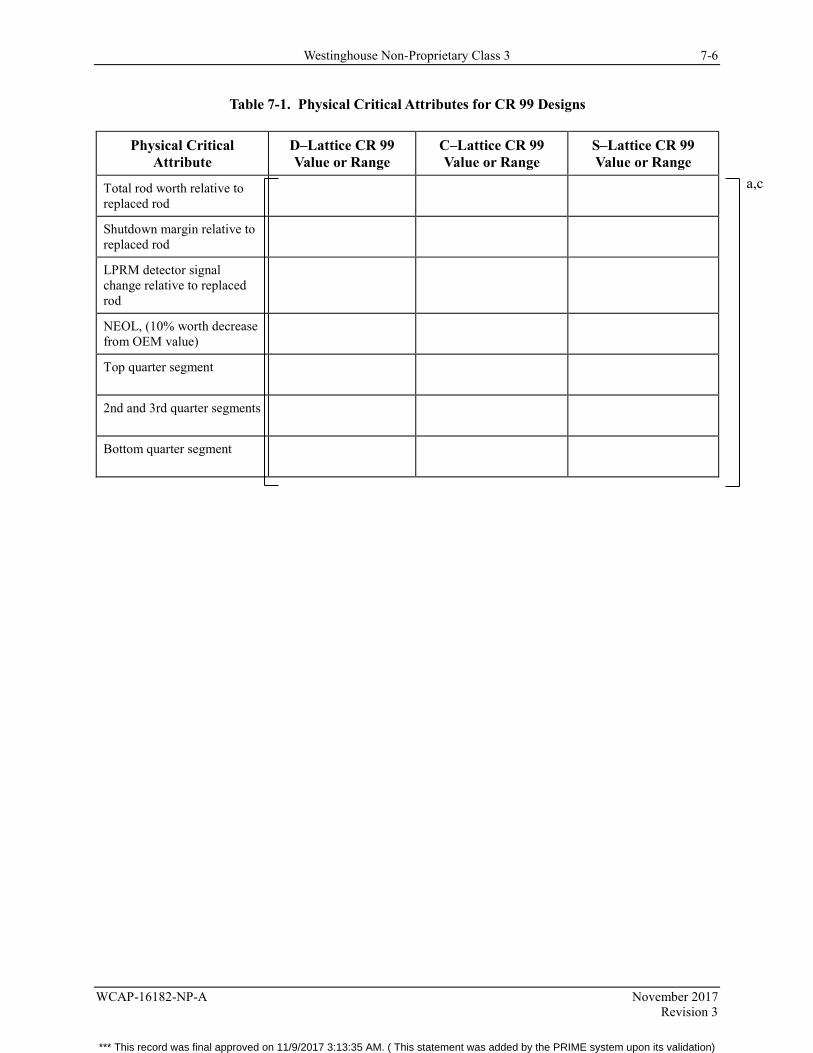
Westinghouse Non-Proprietary Class 3 7-6
WCAP-16182-NP-A November 2017 Revision 3
Table 7-1. Physical Critical Attributes for CR 99 Designs
Physical Critical Attribute
D–Lattice CR 99 Value or Range
C–Lattice CR 99 Value or Range
S–Lattice CR 99 Value or Range
Total rod worth relative to replaced rod
Shutdown margin relative to replaced rod
LPRM detector signal change relative to replaced rod
NEOL, (10% worth decrease from OEM value)
Top quarter segment
2nd and 3rd quarter segments
Bottom quarter segment
a,c
*** This record was final approved on 11/9/2017 3:13:35 AM. ( This statement was added by the PRIME system upon its validation)
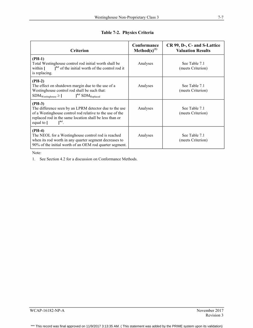
Westinghouse Non-Proprietary Class 3 7-7
WCAP-16182-NP-A November 2017 Revision 3
Table 7-2. Physics Criteria
Criterion Conformance Method(s)(1)
CR 99, D-, C- and S-Lattice Valuation Results
(PH-1) Total Westinghouse control rod initial worth shall be within [ ]a,c of the initial worth of the control rod it is replacing.
Analyses
See Table 7.1
(meets Criterion)
(PH-2) The effect on shutdown margin due to the use of a Westinghouse control rod shall be such that: SDMWestinghouse ≥ [ ]a,c SDMReplaced
Analyses
See Table 7.1
(meets Criterion)
(PH-3) The difference seen by an LPRM detector due to the use of a Westinghouse control rod relative to the use of the replaced rod in the same location shall be less than or equal to [ ]a,c.
Analyses
See Table 7.1
(meets Criterion)
(PH-4) The NEOL for a Westinghouse control rod is reached when its rod worth in any quarter segment decreases to 90% of the initial worth of an OEM rod quarter segment.
Analyses
See Table 7.1
(meets Criterion)
Note: 1. See Section 4.2 for a discussion on Conformance Methods.
*** This record was final approved on 11/9/2017 3:13:35 AM. ( This statement was added by the PRIME system upon its validation)
Westinghouse Non-Proprietary Class 3 8-1
WCAP-16182-NP-A November 2017 Revision 3
8 OPERATIONAL EVALUATION
8.1 CRITICAL ATTRIBUTES
The critical attributes for operational related items are given in Table 8-1. The attribute values used for the CR 99 are also included in the table.
8.2 ATTRIBUTES DISCUSSION
8.2.1 Nominal Wing Thickness
The most important dimensional parameter with respect to compatibility with fuel and fuel channels is the control rod envelope discussed in subsection 8.2.9 below. However, nominal wing thickness is also an important parameter that should be examined for different rod designs.
8.2.2 Maximum Button Thickness
Along with the envelope dimensions, this parameter is important with respect to fuel and channel compatibility. The button is the feature which touches the adjacent fuel channels, helping to keep the control rod centered in the gap between the fuel assemblies.
The CR 99 control rod can also be delivered with no button (Reference 13).
8.2.3 Maximum Wing Span
Maximum wing span is important to compatibility of the rod with core internals and CRD components (e.g., fit through the fuel support piece and fit in the guide tube).
8.2.4 Maximum Velocity Limiter Diameter (With Rollers Installed)
This parameter is important in ensuring compatibility with the CRD system, in particular the guide tube. The rollers on the end of the velocity limiter ride against the inside of the guide tube. The maximum diameter of the velocity limiter with the rollers installed must be such that the rod can travel freely up and down in the guide tube without binding.
8.2.5 Total Weight
Total weight for a control rod must be less than that for which the CRD system was designed.
8.2.6 Overall Length
Overall length is important with respect to interfacing with the CRD system and core internals.
*** This record was final approved on 11/9/2017 3:13:35 AM. ( This statement was added by the PRIME system upon its validation)

Westinghouse Non-Proprietary Class 3 8-2
WCAP-16182-NP-A November 2017 Revision 3
8.2.7 Velocity Limiter/Coupling Design
The design of the velocity limiter is important with respect to the free fall velocity assumed in the Control Rod Drop Accident.
Coupling (socket) design is important since this component provides the control rod interface with the CRD system.
8.2.8 Handle Design
Westinghouse has manufactured control rods with both single and double handles. To ensure compatibility with the rod handling equipment, the handle design of the Westinghouse control rod should be checked against the design of the replaced rod.
In general, the original rods for D-Lattice plants were built with single handles, C-Lattice plants have a mix of single and double handle rods, and S-Lattice plants have double handle rods.The control rods can also be delivered with a core grid support, which allows all four surrounding bundles to be removed without needing a blade guide to hold the control rod in place, provided that the control rod is fully inserted. This means that the handle will be extended up to 2.8 in. (72 mm). When the rod is completely inserted, the support will extend into the core grid. When the rod is completely withdrawn, the handle will experience additional neutron fluence compared with the standard handle. This additional fluence does not limit the use of the rod since the handle is not stressed during operation.
8.2.9 Envelope
The envelope figure for a Westinghouse control rod shows the maximum thickness of the blade as well as the maximum allowed twist and bow along the full length of the control rod.
This envelope is checked for every control rod along its full length in a full length test fixture as part of the manufacturing process.
This envelope is important in determining proper rod interface with fuel, fuel channels, and other core internals.
*** This record was final approved on 11/9/2017 3:13:35 AM. ( This statement was added by the PRIME system upon its validation)
Westinghouse Non-Proprietary Class 3 8-3
WCAP-16182-NP-A November 2017 Revision 3
8.3 OPERATIONAL CRITERIA AND DISCUSSION
The following criteria are shown in Table 8-2 along with the conformance method(s) required to confirm that the criteria are met. CR 99 evaluation results are also shown.
8.3.1 Operational Criterion 1 (OP-1)
Criterion
The Westinghouse control rod socket shall be compatible with the existing CRD coupling device (spud).
Discussion
A good coupling design ensures that (1) the control rod can be coupled to the drive when initially installed, (2) the control rod will remain coupled during operation, and (3) the control rod can be uncoupled when the rod is to be shuffled or removed.
8.3.2 Operational Criterion 2 (OP-2)
Criterion
The Westinghouse control rod weight shall be similar to the nominal weight of the OEM rod.
Discussion
The control rod cannot significantly exceed the nominal weight of the OEM rod due to considerations of scram capability, scram times and free fall (rod drop) characteristics. However the control rod shall not be significantly below the weight of the OEM rod due to settling capability, which depends on the weight of the control rod to cause it to settle into its final position during normal insertion and withdrawal.
8.3.3 Operational Criterion 3 (OP-3)
Criterion
The Westinghouse control rod shall be compatible with existing fuel, fuel channels, and core internals.
Discussion
This criterion is important to ensure that normal operation and scram capability are not impacted, i.e., the control rod will not damage surrounding fuel channels, and will fit in the core.
*** This record was final approved on 11/9/2017 3:13:35 AM. ( This statement was added by the PRIME system upon its validation)
Westinghouse Non-Proprietary Class 3 8-4
WCAP-16182-NP-A November 2017 Revision 3
8.3.4 Operational Criterion 4 (OP-4)
Criterion
The Westinghouse control rod shall be compatible with control rod handling equipment.
Discussion
This criterion would only be of concern in cases where the Westinghouse control rod handle design is different from that which it is replacing. Examples would be providing a double handled rod for a plant originally supplied with single handled rods or supplying rods with extended handles.
Compatibility with rod handling equipment is not a safety issue but, nevertheless, must be investigated to ensure that the handling equipment can move, install, and remove the control rods.
8.3.5 Operational Criterion 5 (OP-5)
Criterion
The Westinghouse control rod free fall velocity shall be consistent with the design basis velocity.
Discussion
This criterion (along with OP-2) ensures that any Westinghouse control rod design is consistent with the control rod free fall assumptions in the plant’s safety analysis for the Control Rod Drop Accident.
The velocity limiter design for the CR 99 is identical to the design of the OEM control rods. This, in combination with control rod weights less than those assumed in the design of the CRD system, ensures that the CR 99 meets Criterion OP-5.
In addition, free fall velocity tests of Westinghouse control rods have been performed (Reference 32) that show that Westinghouse control rods meet this criterion.
8.3.6 Operational Criterion 6 (OP-6)
Criterion
The Westinghouse control rod shall not adversely affect scram times and settling capability in the reactor.
Discussion
In conjunction with OP-2, this criterion ensures that scram times will be consistent with those assumed in the plant’s safety analyses. In addition, it ensures that any Westinghouse control rod design also settles normally when withdrawn or inserted which, while not a direct safety concern, is a necessary operational consideration.
*** This record was final approved on 11/9/2017 3:13:35 AM. ( This statement was added by the PRIME system upon its validation)
Westinghouse Non-Proprietary Class 3 8-5
WCAP-16182-NP-A November 2017 Revision 3
8.3.7 Operational Criterion 7 (OP-7)
Criterion
Flow-induced vibration of the Westinghouse control rods shall not cause detrimental fretting of the rod or fuel channels.
Discussion
The criterion ensures that control rod vibration, which may be induced by coolant flow in guide tubes and/or in the core, does not have any adverse effect on the control rod or on adjacent fuel channels.
The Westinghouse control rod is designed to have similar clearances to guide tubes and fuel channels as the original control rod. As a result, flow velocities and flow patterns, and thus, rod vibrations will not be significantly changed. In addition, interfacing surfaces between the control rod and channel are designed to have sufficiently large contact area to avoid fretting.
8.3.8 Operational Criterion 8 (OP-8)
Criterion
Mechanical End of Life for all new Westinghouse control rod designs should be greater than or equal to the Nuclear End of Life.
Discussion
This criterion is set as a design goal. Nevertheless, historical in-reactor experience has shown that there is a possibility of unexpected cracking due to B4C swelling, material cold work, IASCC, etc. In reality, a crack in a Westinghouse control rod has no impact on the safety function of the rod. Rather, the concern is with eventual wash-out of boron carbide, resulting in unmonitored control rod worth reduction. Hot cell examinations and neutron radiography in reactor pools have shown that the loss of B4C in Westinghouse control rods with B4C powder (e.g., CR 70) through leaching and washout is very limited in adjacent not cracked holes during the course of one or even several operating cycles. [ ]a,c
Westinghouse has a policy to follow lead control rods of each design to high burnups by performing inspections. From these inspections, guidelines for operation and the need for further inspections of the various designs are formulated.
3rd Generation CR 99 Surveillance Program
Inspections have been performed on six leading 3rd generation CR 99 control rods, that were operated in two Swedish BWRs to almost 80% of their nuclear life, with positive results, i.e., no cracking. Following its policy, Westinghouse will continue to inspect the leading rods at higher exposures, close to NEOL, in order to verify the CR 99 design.
*** This record was final approved on 11/9/2017 3:13:35 AM. ( This statement was added by the PRIME system upon its validation)
Westinghouse Non-Proprietary Class 3 8-6
WCAP-16182-NP-A November 2017 Revision 3
An inspection plan has been developed for D, C, and S lattice plants as follows:
• A minimum of two (2) 3rd generation CR 99 control rods will be followed at operation in high duty locations in a D, C, and S-lattice, US or international BWR.
• Additional 3rd generation CR 99 control rods are operated in other US BWRs with the intent that they remain at lower depletion than the two lead-depletion 3rd generation CR 99 control rods at the designated BWRs. Should other control rods at a domestic or international BWRs become the highest depletion in the BWR fleet, they will become the control rods inspected per this surveillance program.
• The two lead-depletion control rods will be irradiated, achieving as close to NEOL as practical (target minimum 90% of end of life).
• For refueling outages in which the depletion of the lead 3rd generation CR 99 control rods are greater than 75% of design life, the two highest depletion 3rd generation CR 99 control rods will be visually inspected on all eight surfaces on each control rod.
• For 3rd generation CR 99 control rods inserted in the opposite lattice type as the lead depletion units, the two (2) highest depletion control rods shall be visually inspected during refueling outages where the control rods exceeds 90% of design NEOL. These visual inspections shall consist of an inspection of all eight faces of the control rod. For the purposes of this surveillance program, D and S lattice applications are considered equivalent, since the geometry of the absorber holes and absorber pins are identical. For example, if the lead depletion control rods are in a D or S lattice plant, inspection of the lead C lattice 3rd generation CR 99 control rods shall be performed during the outages where the depletion exceeds 90% of the design nuclear life. Conversely, if the lead inspection 3rd generation CR 99 control rods are in a C lattice plant, additional inspections of D and S lattice 3rd generation CR 99 control rods shall be performed during outages where the depletion exceeds 90% of the design nuclear life.
• Should a material integrity issue be observed, Westinghouse will arrange for additional inspections, if necessary, to determine root cause and if appropriate, recommend a revised lifetime limit to the NRC based on the inspections and other applicable information available.
• Westinghouse will report the results of the visual inspections of the 3rd generation CR 99 control rods to the NRC within 12 months of when they were performed.
*** This record was final approved on 11/9/2017 3:13:35 AM. ( This statement was added by the PRIME system upon its validation)
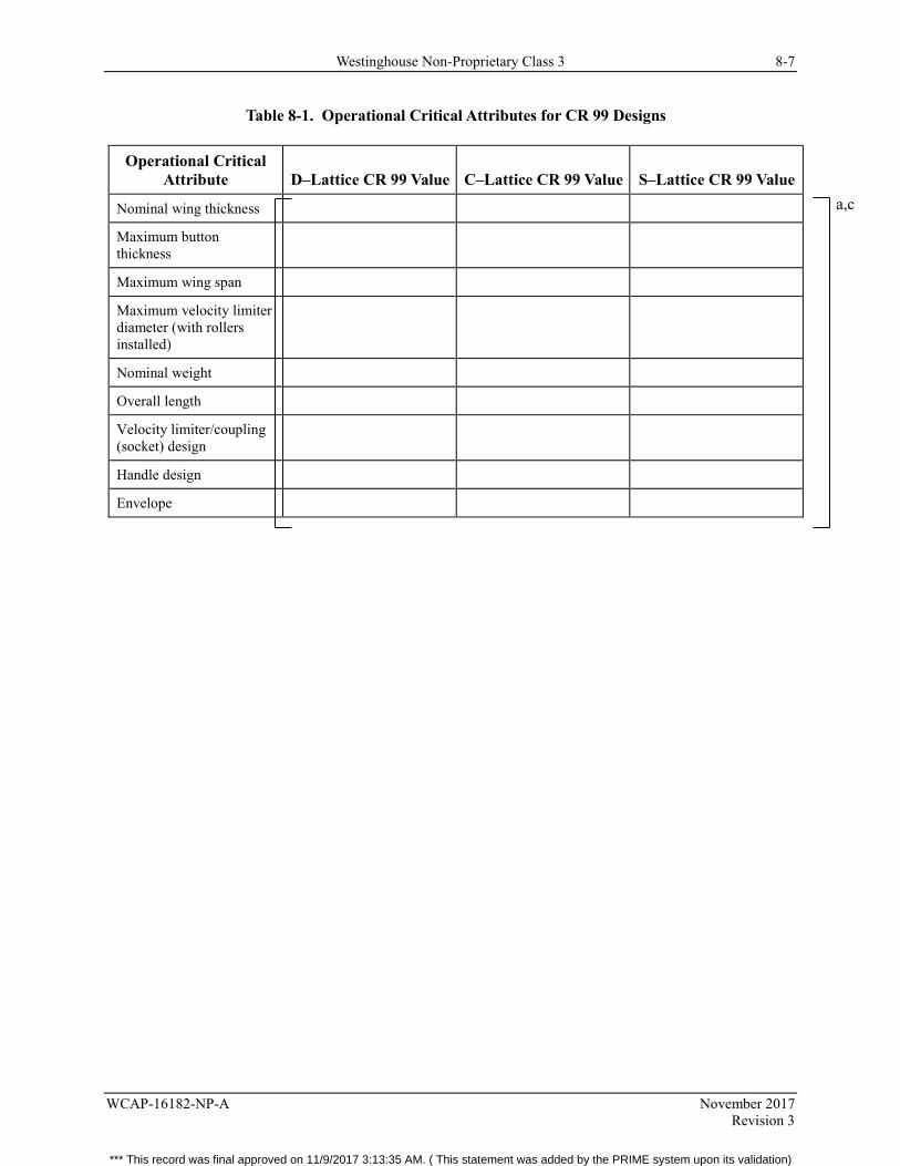
Westinghouse Non-Proprietary Class 3 8-7
WCAP-16182-NP-A November 2017 Revision 3
Table 8-1. Operational Critical Attributes for CR 99 Designs
Operational Critical Attribute D–Lattice CR 99 Value C–Lattice CR 99 Value S–Lattice CR 99 Value
Nominal wing thickness
Maximum button thickness
Maximum wing span
Maximum velocity limiter diameter (with rollers installed)
Nominal weight
Overall length
Velocity limiter/coupling (socket) design
Handle design
Envelope
a,c
*** This record was final approved on 11/9/2017 3:13:35 AM. ( This statement was added by the PRIME system upon its validation)
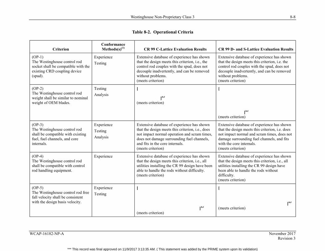
Westinghouse Non-Proprietary Class 3 8-8
WCAP-16182-NP-A November 2017 Revision 3
Table 8-2. Operational Criteria
Criterion Conformance Methods(s)(1) CR 99 C-Lattice Evaluation Results CR 99 D- and S-Lattice Evaluation Results
(OP-1) The Westinghouse control rod socket shall be compatible with the existing CRD coupling device (spud).
Experience Testing
Extensive database of experience has shown that the design meets this criterion, i.e., the control rod couples with the spud, does not decouple inadvertently, and can be removed without problems. (meets criterion)
Extensive database of experience has shown that the design meets this criterion, i.e. the control rod couples with the spud, does not decouple inadvertently, and can be removed without problems. (meets criterion)
(OP-2) The Westinghouse control rod weight shall be similar to nominal weight of OEM blades.
Testing Analysis
[ ]a,c (meets criterion)
[ ]a,c (meets criterion)
(OP-3) The Westinghouse control rod shall be compatible with existing fuel, fuel channels, and core internals.
Experience Testing Analysis
Extensive database of experience has shown that the design meets this criterion, i.e., does not impact normal operation and scram times, does not damage surrounding fuel channels, and fits in the core internals. (meets criterion)
Extensive database of experience has shown that the design meets this criterion, i.e. does not impact normal and scram times, does not damage surrounding fuel channels, and fits with the core internals. (meets criterion)
(OP-4) The Westinghouse control rod shall be compatible with control rod handling equipment.
Experience Extensive database of experience has shown that the design meets this criterion, i.e., all utilities installing the CR 99 design have been able to handle the rods without difficulty. (meets criterion)
Extensive database of experience has shown that the design meets this criterion, i.e., all utilities installing the CR 99 design have been able to handle the rods without difficulty. (meets criterion)
(OP-5) The Westinghouse control rod free fall velocity shall be consistent with the design basis velocity.
Experience Testing
[ ]a,c (meets criterion)
[ ]a,c (meets criterion)
*** This record was final approved on 11/9/2017 3:13:35 AM. ( This statement was added by the PRIME system upon its validation)
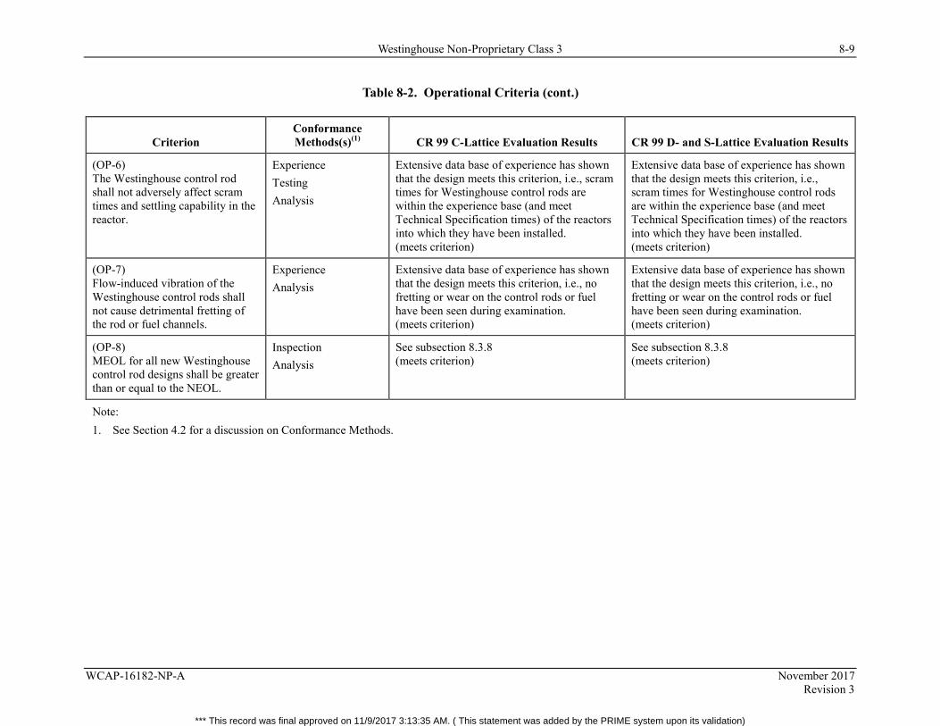
Westinghouse Non-Proprietary Class 3 8-9
WCAP-16182-NP-A November 2017 Revision 3
Table 8-2. Operational Criteria (cont.)
Criterion Conformance Methods(s)(1) CR 99 C-Lattice Evaluation Results CR 99 D- and S-Lattice Evaluation Results
(OP-6) The Westinghouse control rod shall not adversely affect scram times and settling capability in the reactor.
Experience Testing Analysis
Extensive data base of experience has shown that the design meets this criterion, i.e., scram times for Westinghouse control rods are within the experience base (and meet Technical Specification times) of the reactors into which they have been installed. (meets criterion)
Extensive data base of experience has shown that the design meets this criterion, i.e., scram times for Westinghouse control rods are within the experience base (and meet Technical Specification times) of the reactors into which they have been installed. (meets criterion)
(OP-7) Flow-induced vibration of the Westinghouse control rods shall not cause detrimental fretting of the rod or fuel channels.
Experience Analysis
Extensive data base of experience has shown that the design meets this criterion, i.e., no fretting or wear on the control rods or fuel have been seen during examination. (meets criterion)
Extensive data base of experience has shown that the design meets this criterion, i.e., no fretting or wear on the control rods or fuel have been seen during examination. (meets criterion)
(OP-8) MEOL for all new Westinghouse control rod designs shall be greater than or equal to the NEOL.
Inspection Analysis
See subsection 8.3.8 (meets criterion)
See subsection 8.3.8 (meets criterion)
Note: 1. See Section 4.2 for a discussion on Conformance Methods.
*** This record was final approved on 11/9/2017 3:13:35 AM. ( This statement was added by the PRIME system upon its validation)
Westinghouse Non-Proprietary Class 3 8-10
WCAP-16182-NP-A November 2017 Revision 3
Figure 8-1. Control Rod Tolerance Envelope D-Lattice, Base Design
a,c
*** This record was final approved on 11/9/2017 3:13:35 AM. ( This statement was added by the PRIME system upon its validation)
Westinghouse Non-Proprietary Class 3 8-11
WCAP-16182-NP-A November 2017 Revision 3
Figure 8-2. Control Rod Tolerance Envelope C-Lattice, Base Design
a,c
*** This record was final approved on 11/9/2017 3:13:35 AM. ( This statement was added by the PRIME system upon its validation)
Westinghouse Non-Proprietary Class 3 8-12
WCAP-16182-NP-A November 2017 Revision 3
Figure 8-3. Control Rod Tolerance Envelope S-Lattice, Base Design
a,c
*** This record was final approved on 11/9/2017 3:13:35 AM. ( This statement was added by the PRIME system upon its validation)
Westinghouse Non-Proprietary Class 3 9-1
WCAP-16182-NP-A November 2017 Revision 3
9 REFERENCES
1. Topical Report, Performance Verification of an Improved BWR Control Rod Design, TR BR 82-98, Revision 1, May 5, 1983 (proprietary).
2. Topical Report, ASEA-ATOM BWR Control Rods for US BWRs, TR UR 85-225, October 1985 (proprietary).
3. Letter, H. N. Berkow (NRC) to E. Tenerz (ASEA-ATOM), Subject: Acceptance for Referencing of Licensing Topical Report TR UR 85-225, “ASEA-ATOM Control Rods for US BWRs,” February 20, 1986.
4. Supplement 1 to TR UR 85-225A, ASEA-ATOM Control Rods for US BWRs, October 1987 (proprietary).
5. Letter, A. C. Thadani (NRC) to E. Tenerz (ASEA-ATOM), Subject: Acceptance as a Reference Document of Supplement 1 to Topical Report TR UR 85-225, “ASEA-ATOM Control Rods for US BWRs,” May 5, 1988.
6. Supplement 2 to TR UR 85-225A, ASEA-ATOM Control Rods for US BWRs.
7. Letter, A. C. Thadani (NRC) to E. Tenerz (ABB ATOM), Subject: Acceptance of Supplement 2 to Topical Report UR-85-225A, “ASEA-ATOM Control Rods for US BWRs as a Reference Document,” August 8, 1989.
8. ABB Report BKE 95-044, B Rebensdorff, “Data to support the replacement of Type 304L SS with Type 316L SS as blade material in ABB BWR control rods,” March 13, 1995.
9. ABB Report BX 90-37, Meeting with the NRC Regarding Cracks in the Dresden 3 Control Rods, March 27, 1990 (proprietary).
10. Letter, ABB-90-520, J. Lindner (ABB) to R. C. Jones (NRC), Subject: Meeting with NRC Regarding Update on Results of ABB Atom BWR Control Rod Inspections and Summary of Forthcoming Actions, December 14, 1990.
11. Letter, ATOF-91-130, J. Lindner (ABB) to L. Phillips (NRC), Subject: Meeting Between NRC and ABB Atom Regarding Control Rod Inspection Results at Millstone, May 29, 1991.
12. Letter, ATOF-91-273, J. Lindner (ABB) to L. Phillips (NRC), Subject: Meeting Between NRC and ABB Atom Regarding Inspection Results and Service Life Guidelines for CR-82 Rods in US Plants, December 27, 1991 (proprietary).
13. Westinghouse Atom Report, BTK 02-104, A. Lundén, Control Rods without Buttons, Nov. 2002.
14. Not used.
*** This record was final approved on 11/9/2017 3:13:35 AM. ( This statement was added by the PRIME system upon its validation)
Westinghouse Non-Proprietary Class 3 9-2
WCAP-16182-NP-A November 2017 Revision 3
15. ABB Report RM 88-1014, The ABB ATOM Computer Model BKM-CRUD (proprietary).
16. Not used.
17. Not used.
18. Not used.
19. Not used.
20. Not used.
21. Not used.
22. Not used.
23. Westinghouse Report BTA 01-080, L. Plobeck, Test of Westinghouse Atom Control Rods for BWR, Normal and Seismic Scram Insertion, 2001 (proprietary).
24. Not used.
25. Not used.
26. Westinghouse Atom Report BCM 98-031, Validation of PHOENIX-4 against Critical Experiments, March 1998 (proprietary).
27. ABB Report UR 87-052, “XYBDRY – Control Rod Nuclear Lifetime Calculations,” February 26, 1987 (proprietary).
28. Not used.
29. Not used.
30. Not used.
31. ABB Report UR 87-102 Rev. 1, “ASEA-ATOM Control Rods for BWR 2/3/4/5/6 Service Limit Recommendations,” April 15, 1987 (proprietary).
32. Westinghouse Atom Report, BTA 02-154, L Plobeck, Test of Westinghouse atom Control Rods for BWR Dropping Speed, Oct. 2002 (proprietary).
33. Westinghouse Report, BTK 06-1597, Mechanical Design Report CR 99 Control Rods for S-Lattice BWR6, 2006 (proprietary).
34. Not used.
*** This record was final approved on 11/9/2017 3:13:35 AM. ( This statement was added by the PRIME system upon its validation)
Westinghouse Non-Proprietary Class 3 9-3
WCAP-16182-NP-A November 2017 Revision 3
35. Westinghouse Report BTF 06-1583, Nuclear Design Characteristics of Westinghouse Atom Control Rod CR 99 for BWR6 S-Lattice Reactors, 2006 (proprietary).
36. Westinghouse Report BTF 06-1584, Nuclear Design Characteristics of Westinghouse Control Rod CR 99 for BWR2/3/4 D-Lattice Reactors, 2006 (proprietary).
37. Westinghouse Report BTF 06-1623, Nuclear Design Characteristics of Westinghouse Control Rod CR 99 for BWR4/5 C-Lattice Reactors, 2006 (proprietary).
38. WCAP-16182-P-A, Revision 0, “Westinghouse BWR Control Rod CR 99 Licensing Report,” March 2005 (proprietary).
39. Westinghouse Report, SES 12-091 Rev. 1, M. Jinnestrand, Methodology of Helium Pressure
Calculation in Westinghouse CR 99 BWR Control Rods with HIPed Pins by Statistical Models, July 2012 (proprietary).
40. Westinghouse Report, SES 15-005 Rev. 0, M. Jinnestrand, Structural Verification of Control Rod CR 99 Generation 3 for BWR/2-4 and BWR/6 Reactors with S- & D-Lattice, 2015 (proprietary).
41. Westinghouse Report, SES 15-013 Rev. 0, M. Jinnestrand, Structural Verification of Control Rod CR 99 Generation 3 for BWR4/5 Reactors with C-Lattice, 2015 (proprietary).
42. Westinghouse Report, SES 15-011 Rev. 0, M. Jinnestrand, Modelling of CR 99 Control Rod Blade Swelling, March 2015 (proprietary).
43. PRIS-EC Project FIKS-CT-2000-00084, 5th Framework Program, Final Report June 2004.
44. Westinghouse Report SES 16-061 Rev. 0, M. Jinnestrand, Seismic Analysis of Westinghouse Control Rod CR 99 Generation 3, 2016 (proprietary).
*** This record was final approved on 11/9/2017 3:13:35 AM. ( This statement was added by the PRIME system upon its validation)
Westinghouse Non-Proprietary Class 3
WCAP-16182-NP-A November 2017 Revision 3
Section C
Submittal of Responses to Requests for Additional Information
*** This record was final approved on 11/9/2017 3:13:35 AM. ( This statement was added by the PRIME system upon its validation)
Westinghouse Electric Company Nuclear Services P.O. Box 355 Pittsburgh, Pennsylvania 15230-0355 USA
Direct tel: (412) 374-4643 Direct fax: (412) 374-3846
e-mail: [email protected]
U.S. Nuclear Regulatory Commission Document Control Desk Washington, DC 20555-0001
LTR-NRC-09-50
November 10, 2009
Subject: Response to NRC Request for Additional Information Re: Westinghouse Electric Company Topical Report (TR) WCAP-16182-P-A, Addendum 1, “Westinghouse BWR Control Rod CR 99 Licensing Report - Addendum 1, Updated Design Limits,” dated November 6, 2008 (TAC NO. MD7989) and
Submittal of WCAP-16182-P-A/WCAP-16182-NP-A, Revision 1, “Westinghouse BWR Control Rod CR 99 Licensing Report - Update to Mechanical Design Limits,” dated October 2009 (Proprietary/Non-Proprietary).
Enclosed are Proprietary (P) and Non-Proprietary (NP) copies of responses and requested supporting information to the NRC’s Request for Additional Information (RAI), Re: Westinghouse Electric Company Topical Report (TR) WCAP-16182-P-A, Addendum 1, “Westinghouse BWR Control Rod CR 99 Licensing Report - Addendum 1, Updated Design Limits,” dated November 6, 2008. As follow-up to the actions discussed between Westinghouse’s Tom Rodack and NRC Branch Chief Tony Mendiola on March 11-12, 2009, and later with the NRC review staff during a teleconference on March 18, 2009, this response submits a revised and reformatted Revision 1 version of the proposed update to the CR 99 control rod design limits previously submitted as WCAP-16182-P-A, Addendum 1. The enclosed P and NP copies of WCAP-16182-P-A/NP-A, Revision 1, “Westinghouse BWR Control Rod CR 99 Licensing Report - Update to Mechanical Design Limits,” are provided to incorporate overall staff comments and to supersede the previous Addendum 1 version of the proposed update to the CR 99 topical design report in its entirety. Also as requested in the RAI, copies of proprietary references (Refs. 33-37) added by Revision 1, are enclosed for staff information in support of the proposed topical review. Should additional information be needed in regard to the enclosed response, please contact Michael Riggs in Westinghouse Fuel Engineering Licensing at 254-396-6392. Also enclosed is:
1. One (1) copy of the Application for Withholding, AW-09-2700 (Non-Proprietary) with Proprietary Information Notice.
2. One (1) copy of Affidavit (Non-Proprietary). This submittal contains proprietary information of Westinghouse Electric Company, LLC. In conformance with the requirements of 10 CFR Section 2.390, as amended, of the Commission’s regulations, we are enclosing with this submittal an Application for Withholding from Public Disclosure and an affidavit. The affidavit sets forth the basis on which the information identified as proprietary may be withheld from public disclosure by the Commission. Correspondence with respect to the affidavit or Application for Withholding should reference AW-09-2700 and should be addressed to J. A. Gresham, Manager, Regulatory Compliance and Plant Licensing, Westinghouse Electric Company LLC, P.O. Box 355, Pittsburgh, Pennsylvania 15230-0355.
WCAP-16182-NP-A____________________________________________________________________________________
November 2017 Revision 3
*** This record was final approved on 11/9/2017 3:13:35 AM. ( This statement was added by the PRIME system upon its validation)

WCAP-16182-NP-A____________________________________________________________________________________
November 2017 Revision 3
*** This record was final approved on 11/9/2017 3:13:35 AM. ( This statement was added by the PRIME system upon its validation)

WCAP-16182-NP-A____________________________________________________________________________________
November 2017 Revision 3
*** This record was final approved on 11/9/2017 3:13:35 AM. ( This statement was added by the PRIME system upon its validation)
WCAP-16182-NP-A____________________________________________________________________________________
November 2017 Revision 3
*** This record was final approved on 11/9/2017 3:13:35 AM. ( This statement was added by the PRIME system upon its validation)
AW-09-2700
-2-
(1) I am Manager, Regulatory Compliance and Plant Licensing, in Nuclear Services, Westinghouse Electric
Company LLC (Westinghouse) and as such, I have been specifically delegated the function of reviewing the
proprietary information sought to be withheld from public disclosure in connection with nuclear power plant
licensing and rulemaking proceedings, and am authorized to apply for its withholding on behalf of
Westinghouse.
(2) I am making this Affidavit in conformance with the provisions of 10 CFR Section 2.390 of the Commission's
regulations and in conjunction with the Westinghouse "Application for Withholding" accompanying this
Affidavit.
(3) I have personal knowledge of the criteria and procedures utilized by Westinghouse in designating information
as a trade secret, privileged or as confidential commercial or financial information.
(4) Pursuant to the provisions of paragraph (b)(4) of Section 2.390 of the Commission's regulations, the following
is furnished for consideration by the Commission in determining whether the information sought to be
withheld from public disclosure should be withheld.
(i) The information sought to be withheld from public disclosure is owned and has been held in
confidence by Westinghouse.
(ii) The information is of a type customarily held in confidence by Westinghouse and not customarily
disclosed to the public. Westinghouse has a rational basis for determining the types of information
customarily held in confidence by it and, in that connection, utilizes a system to determine when and
whether to hold certain types of information in confidence. The application of that system and the
substance of that system constitutes Westinghouse policy and provides the rational basis required.
Under that system, information is held in confidence if it falls in one or more of several types, the
release of which might result in the loss of an existing or potential competitive advantage, as follows:
(a) The information reveals the distinguishing aspects of a process (or component, structure,
tool, method, etc.) where prevention of its use by any of Westinghouse's competitors
without license from Westinghouse constitutes a competitive economic advantage over
other companies.
(b) It consists of supporting data, including test data, relative to a process (or component,
structure, tool, method, etc.), the application of which data secures a competitive
economic advantage, e.g., by optimization or improved marketability.
(c) Its use by a competitor would reduce his expenditure of resources or improve his
competitive position in the design, manufacture, shipment, installation, assurance of
quality, or licensing a similar product.
WCAP-16182-NP-A____________________________________________________________________________________
November 2017 Revision 3
*** This record was final approved on 11/9/2017 3:13:35 AM. ( This statement was added by the PRIME system upon its validation)

AW-09-2700
-3-
(d) It reveals cost or price information, production capacities, budget levels, or commercial
strategies of Westinghouse, its customers or suppliers.
(e) It reveals aspects of past, present, or future Westinghouse or customer funded
development plans and programs of potential commercial value to Westinghouse.
(f) It contains patentable ideas, for which patent protection may be desirable.
There are sound policy reasons behind the Westinghouse system which include the following:
(a) The use of such information by Westinghouse gives Westinghouse a competitive
advantage over its competitors. It is, therefore, withheld from disclosure to protect the
Westinghouse competitive position.
(b) It is information which is marketable in many ways. The extent to which such
information is available to competitors diminishes the Westinghouse ability to sell
products and services involving the use of the information.
(c) Use by our competitor would put Westinghouse at a competitive disadvantage by reducing his expenditure of resources at our expense.
(d) Each component of proprietary information pertinent to a particular competitive
advantage is potentially as valuable as the total competitive advantage. If competitors
acquire components of proprietary information, any one component may be the key to the
entire puzzle, thereby depriving Westinghouse of a competitive advantage.
(e) Unrestricted disclosure would jeopardize the position of prominence of Westinghouse in
the world market, and thereby give a market advantage to the competition of those
countries.
(f) The Westinghouse capacity to invest corporate assets in research and development
depends upon the success in obtaining and maintaining a competitive advantage.
(iii) The information is being transmitted to the Commission in confidence and, under the provisions of
10 CFR Section 2.390, it is to be received in confidence by the Commission.
(iv) The information sought to be protected is not available in public sources or available information has
not been previously employed in the same original manner or method to the best of our knowledge
and belief.
WCAP-16182-NP-A____________________________________________________________________________________
November 2017 Revision 3
*** This record was final approved on 11/9/2017 3:13:35 AM. ( This statement was added by the PRIME system upon its validation)

AW-09-2700
-4-
(v) The proprietary information sought to be withheld in this submittal is that which is appropriately
marked “Response to NRC Request for Additional Information Re: Westinghouse Electric Company
Topical Report (TR) WCAP-16182-P-A, Addendum 1, ‘Westinghouse BWR Control Rod CR 99
Licensing Report - Addendum 1, Updated Design Limits,’ dated November 6, 2008 (TAC NO.
MD7989) and Submittal of WCAP-16182-P-A/WCAP-16182-NP-A, Revision 1, “Westinghouse
BWR Control Rod CR 99 Licensing Report - Update to Mechanical Design Limits,” dated October
2009 (Proprietary/Non-proprietary),” and information only copies of the following proprietary
references (Revision 1 References 33-37);
(33.) Westinghouse Report, BTK 06-1597, “Mechanical Design Report CR 99 Control Rods for
S-Lattice BWR6,” dated 2007 (Proprietary),
(34.) Westinghouse Report BTM 09-0624, G. Eriksson, “BWR Control Rod CR 99 for BWR/2-4
and BWR/6 Reactors with D- and S-Lattice. Mechanical End of Life prediction and Stress
analysis,” dated 2009 (Proprietary),
(35.) Westinghouse Report BTF 06-1583, “Nuclear Design Characteristics of Westinghouse
Control Rod CR 99 for BWR6 S-Lattice Reactors,” dated 2007 (Proprietary),
(36.) Westinghouse Report BTF 06-1584, “Nuclear Design Characteristics of Westinghouse
Control Rod CR 99 for BWR2/3/4 D-Lattice Reactors,” dated 2007 (Proprietary), and
(37.) Westinghouse Report BTF 06-1623, “Nuclear Design Characteristics of Westinghouse
Control Rod CR 99 for BWR4/5 C-Lattice Reactors,” dated 2007 (Proprietary),
for submittal to the Commission, being transmitted by Westinghouse letter (LTR-NRC-09-50) and
Application for Withholding Proprietary Information from Public Disclosure, to the Document
Control Desk. The proprietary information as submitted by Westinghouse Electric Company is that
associated with the response to NRC Request for Additional Information Re: Westinghouse Electric
Company Topical Report (TR) WCAP-16182-P-A, Addendum 1, dated November 6, 2008.
This information is part of that which will enable Westinghouse to:
(a) Obtain generic NRC licensed approval for revised design criteria which will allow for
extended component life of the Westinghouse CR 99 BWR control rods.
(b) Meet NRC regulatory requirements in support of a Westinghouse product.
Further, this information has substantial commercial value as follows:
(a) Westinghouse can use this topical design report to further enhance their licensing position
over their competitors.
(b) Assist customers to obtain license changes.
Public disclosure of this proprietary information is likely to cause substantial harm to the competitive
position of Westinghouse because it would enhance the ability of competitors to provide similar
WCAP-16182-NP-A____________________________________________________________________________________
November 2017 Revision 3
*** This record was final approved on 11/9/2017 3:13:35 AM. ( This statement was added by the PRIME system upon its validation)

AW-09-2700
-5-
technical evaluation justifications and licensing defense services for commercial power reactors
without commensurate expenses. Also, public disclosure of the information would enable others to
use the information to meet NRC requirements for licensing documentation without purchasing the
right to use the information.
The development of the technology described in part by the information is the result of applying the
results of many years of experience in an intensive Westinghouse effort and the expenditure of a
considerable sum of money.
In order for competitors of Westinghouse to duplicate this information, similar technical programs
would have to be performed and a significant manpower effort, having the requisite talent and
experience, would have to be expended.
Further the deponent sayeth not.
WCAP-16182-NP-A____________________________________________________________________________________
November 2017 Revision 3
*** This record was final approved on 11/9/2017 3:13:35 AM. ( This statement was added by the PRIME system upon its validation)
PROPRIETARY INFORMATION NOTICE
Transmitted herewith are proprietary and/or non-proprietary versions of documents furnished to the NRC in
connection with requests for generic and/or plant-specific review and approval.
In order to conform to the requirements of 10 CFR 2.390 of the Commission's regulations concerning the protection
of proprietary information so submitted to the NRC, the information which is proprietary in the proprietary versions
is contained within brackets, and where the proprietary information has been deleted in the non-proprietary versions,
only the brackets remain (the information that was contained within the brackets in the proprietary versions having
been deleted). The justification for claiming the information so designated as proprietary is indicated in both
versions by means of lower case letters (a) through (f) located as a superscript immediately following the brackets
enclosing each item of information being identified as proprietary or in the margin opposite such information.
These lower case letters refer to the types of information Westinghouse customarily holds in confidence identified in
Sections (4)(ii)(a) through (4)(ii)(f) of the affidavit accompanying this transmittal pursuant to 10 CFR 2.390(b)(1).
COPYRIGHT NOTICE
The reports transmitted herewith each bear a Westinghouse copyright notice. The NRC is permitted to make the
number of copies of the information contained in these reports which are necessary for its internal use in connection
with generic and plant-specific reviews and approvals as well as the issuance, denial, amendment, transfer, renewal,
modification, suspension, revocation, or violation of a license, permit, order, or regulation subject to the
requirements of 10 CFR 2.390 regarding restrictions on public disclosure to the extent such information has been
identified as proprietary by Westinghouse, copyright protection notwithstanding. With respect to the
non-proprietary versions of these reports, the NRC is permitted to make the number of copies beyond those
necessary for its internal use which are necessary in order to have one copy available for public viewing in the
appropriate docket files in the public document room in Washington, DC and in local public document rooms as
may be required by NRC regulations if the number of copies submitted is insufficient for this purpose. Copies made
by the NRC must include the copyright notice in all instances and the proprietary notice if the original was identified
as proprietary.
WCAP-16182-NP-A____________________________________________________________________________________
November 2017 Revision 3
*** This record was final approved on 11/9/2017 3:13:35 AM. ( This statement was added by the PRIME system upon its validation)
Westinghouse Non-Proprietary Class 3 LTR-NRC-09-50 NP-Attachment TAC No. MD7989
Page 1 of 6
Response to NRC Request for Additional Information by the Office of Nuclear Reactor Regulation
for Topical Report WCAP-16182-P-A, Addendum 1, “Westinghouse BWR Control Rod CR 99 Licensing Report -
Addendum 1, Updated Design Limits” (Non-Proprietary)
November 2009
Westinghouse Electric Company
P.O. Box 355 Pittsburgh, Pennsylvania 15230-0355
© 2009 Westinghouse Electric Company LLC
All Rights Reserved
WCAP-16182-NP-A____________________________________________________________________________________
November 2017 Revision 3
*** This record was final approved on 11/9/2017 3:13:35 AM. ( This statement was added by the PRIME system upon its validation)
LTR-NRC-09-50 NP-Attachment TAC No. MD7989
Page 2 of 6
RESPONSE TO REQUEST FOR ADDITIONAL INFORMATION (RAI) FOR WESTINGHOUSE BWR CONTROL ROD CR 99 LICENSING REPORT
(WCAP-16182-P-A, ADDENDUM 1) Overall response to RAI and submittal of enclosed Revision 1 in lieu of Addendum 1 As follow-up to the actions discussed between Westinghouse’s Tom Rodack and NRC Branch Chief Tony Mendiola on March 11-12, 2009, and later with the NRC review staff during a teleconference on March 18, 2009, this response submits a revised and reformatted Revision 1 version of the proposed update to the CR 99 control rod design limits previously submitted as WCAP-16182-P-A, Addendum 1. The enclosed Proprietary (P) and Non-Proprietary (NP) of WCAP-16182-P-A/NP-A, Revision 1, “Westinghouse BWR Control Rod CR 99 Licensing Report - Update to Mechanical Design Limits,” are provided to incorporate overall staff comments and to supersede the previous Addendum 1 version of the proposed update to the CR 99 topical design report in its entirety. Also as requested in the RAI, copies of updated proprietary references (Revision 1 Refs. 33-37) which have been added to the list of references in Revision 1, are enclosed for staff information in support of the proposed topical’s review. Should additional information be needed in regard to the enclosed response, please contact Michael Riggs at Westinghouse Fuel Engineering Licensing. Responses to individual RAI questions 1. Provide the justification of [ ]a,c If
the justification is based on Westinghouse proprietary reports, then the reports have to be submitted for review.
Response to RAI 1
As described above, the enclosed Revision 1 of the proposed update to CR 99 topical report WCAP-16182-P-A is submitted to supersede the previous Addendum 1 version of the CR 99 topical report in its entirety. To address the staff’s comments that; [ ]a,c As such, the enclosed Revision 1 update to the CR 99 topical report [ ]a,c
WCAP-16182-NP-A____________________________________________________________________________________
November 2017 Revision 3
*** This record was final approved on 11/9/2017 3:13:35 AM. ( This statement was added by the PRIME system upon its validation)
LTR-NRC-09-50 NP-Attachment TAC No. MD7989
Page 3 of 6
[ ]a,c
2. Explain [ ]a,c Response to RAI 2
As described above, the enclosed Revision 1 of the proposed update to CR 99 topical report WCAP-16182-P-A is submitted as part of the overall RAI response and to supersede the previous Addendum 1 version of the CR 99 topical report in its entirety. The Revision 1 updated includes that [ ]a,c
WCAP-16182-NP-A____________________________________________________________________________________
November 2017 Revision 3
*** This record was final approved on 11/9/2017 3:13:35 AM. ( This statement was added by the PRIME system upon its validation)
LTR-NRC-09-50 NP-Attachment TAC No. MD7989
Page 4 of 6
3. Provide the basis of Equation 6.5 on page 6-7 and elaborate the results in D, C, and S lattices. If the justification is based on Westinghouse proprietary reports, then the reports have to be submitted for review.
Response to RAI 3 The bases for Equation 6.5, as previously used in Addendum 1, was provided in Reference 20 of Addendum 1. Included in the previous Reference 20 was the [ ]a,c As discussed above and in response to the staff’s comments, Revision 1 of the proposed update to the CR 99 topical report does not include the use of [ ]a,c As such, the corresponding equation has since been renumbered and replaced by Equation 6.6 in the enclosed Revision 1 update. Also, the Revision 1 update no longer includes the previous Reference 20 from Addendum 1. Instead, the corresponding bases discussion has been revised and is described in more detail in Section 6.4.2 of the Revision 1 update. Typical values for D, C, and S Lattices are also provided at the end of this section. [ ]a,c Reference 19 is the same reference as included in the approved CR 99 topical design report, WCAP-16182-P-A, Revision 0 (March 2005). Also, as requested by this RAI, copies of the updated proprietary references (Refs. 33-37) which have been added to the list of references in Revision 1, are enclosed for staff information in support of the proposed CR 99 topical review.
4. In determining [ irradiation transformation of applicable strength limit between BOL and
MEOL, a dose level of 2.7 dpa was chosen for MEOL on page 6-9. ]a,c Please provide the justification of the dose level. If Westinghouse proprietary reports are involved, then the reports have to be submitted for review.
Response to RAI 4 The discussion of [ ]a,c
WCAP-16182-NP-A____________________________________________________________________________________
November 2017 Revision 3
*** This record was final approved on 11/9/2017 3:13:35 AM. ( This statement was added by the PRIME system upon its validation)
LTR-NRC-09-50 NP-Attachment TAC No. MD7989
Page 5 of 6
As requested by this RAI, copies of the updated proprietary references (Refs. 33-37) which have been added to the list of references in Revision 1, are also enclosed for staff information in support of the proposed CR 99 topical review.
5. In Table 6-4 “Mechanical Related Critical Attributes for CR99,” (a) Define [ “NoExceptional,” ]a,c (b) Provide the basis of the criteria for D, C, and S Lattices, and (c) Explain what
analyses were performed to meet the criteria.
Response to RAI 5 The terms [ ]a,c In the enclosed Revision 1 update, the corresponding bases for the Mechanical End of Life (MEOL) and Stress Analysis are further described in new Reference 34. As described above, copies of updated proprietary references (Refs. 33-37) which have been added to the list of references in Revision 1, are enclosed for staff information in support of the proposed CR 99 topical review.
6. In the REFERENCES section, there are un-reviewed Westinghouse proprietary reports. These
reports need to be submitted for the staff review to determine the safety significance. These reports in accordance with the reference number is listed: 14, 15, 18, 19, 20, 21, 23, 24, 25, 26, 27, 28, 29, 30, and 31.
Response to RAI 6 As discussed above, the enclosed Revision 1 of the proposed update to CR 99 topical report WCAP-16182-P-A is provided to supersede the previously submitted Addendum 1 version of the topical report in its entirety. From the list of proprietary references requested by RAI 6, References 14, 20, 21, 27, 28, and 29 were previously referenced by Addendum 1. These references are now shown in Revision 1 as additional new Refs. 33-37 to the existing list of references already included in approved CR 99 topical report WCAP-16182-P-A, Revision 0. As requested by the above RAIs, copies of these new proprietary references 33-37 which were added in Revision 1, are enclosed for staff information in support of the proposed topical review. In Revision 1, the above proprietary references 15, 18, 19, 23, 24, 25, 26, 30, and 31 continue to refer to the same documents and revision numbers as currently included in approved CR 99 topical report
WCAP-16182-NP-A____________________________________________________________________________________
November 2017 Revision 3
*** This record was final approved on 11/9/2017 3:13:35 AM. ( This statement was added by the PRIME system upon its validation)
LTR-NRC-09-50 NP-Attachment TAC No. MD7989
Page 6 of 6
WCAP-16182-P-A, Revision 0. Copies of these proprietary references were previously either submitted as responses to RAIs or otherwise made available in support of the staff’s review of the currently approved CR 99 topical report (Revision 0).
WCAP-16182-NP-A____________________________________________________________________________________
November 2017 Revision 3
*** This record was final approved on 11/9/2017 3:13:35 AM. ( This statement was added by the PRIME system upon its validation)
(8 Westinghouse
U.S. Nuclear Regulatory Commission Document Control Desk 11555 Rockville Pike Rockville, MD 20852
Westinghouse Electric Company Nuclear Services 1 000 Westinghouse Drive Cranberry Township, Pennsylvania 16066 USA
Direct tel: (412) 374-4643 Direct fax: (724) 720-0754
e-mail: [email protected]
LTR-NRC-11-15, Rev.1
June 6, 2011
Subject: Response to the NRCs Request for Additional Information RE: Westinghouse Electric Company Topical Report WCAP-16182-P-A, Revision 1, "Westinghouse BWR Control Rod CR 99 Licensing Report- Update to Mechanical Design Limits" (TAC No. ME2630) (Proprietary/Non-Proprietary)
Enclosed are copies of the proprietary/non-proprietary versions of a report titled "Response to the NRC's Request for Additional Infonnation RE: Westinghouse Electric Company Topical Report WCAP-16182-P-A, Revision 1, 'Westinghouse BWR Control Rod CR 99 Licensing Report- Update to Mechanical Design Limits'" provided for infonnation only.
Also enclosed is:
1. One (1) copy of the Application for Withholding Proprietary lnfonnation from Public Disclosure, A W -11-3145 (Non-Proprietary), with Proprietary Infonnation Notice and Copyright Notice.
2. One (1) copy of Affidavit (Non-Proprietary).
This submittal contains proprietary infonnation of Westinghouse Electric Company LLC. In confonnance with the requirements of 10 CFR Section 2.390, as amended, of the Commission's regulations, we are enclosing with this submittal an Application for Withholding Proprietary Infonnation from Public Disclosure and an affidavit. The affidavit sets forth the basis on which the information identified as proprietary may be withheld from public disclosure by the Commission.
Correspondence with respect to the proprietary aspects of the application for withholding or the Westinghouse affidavit should reference AW-11-3145 and should be addressed to J. A. Gresham, Manager, Regulatory Compliance, Westinghouse Electric Company LLC, Suite 428, 1000 Westinghouse Drive, Cranberry Township, Pennsylvania 16066.
Very truly yours,
~~1:~ Regulatory Compliance
Enclosures cc: E. Lenning
WCAP-16182-NP-A____________________________________________________________________________________
November 2017 Revision 3
*** This record was final approved on 11/9/2017 3:13:35 AM. ( This statement was added by the PRIME system upon its validation)
WCAP-16182-NP-A____________________________________________________________________________________
November 2017 Revision 3
*** This record was final approved on 11/9/2017 3:13:35 AM. ( This statement was added by the PRIME system upon its validation)
WCAP-16182-NP-A____________________________________________________________________________________
November 2017 Revision 3
*** This record was final approved on 11/9/2017 3:13:35 AM. ( This statement was added by the PRIME system upon its validation)
AW-11-3145
2
(1) I am Manager, Regulatory Compliance, in Nuclear Services, Westinghouse Electric
Company LLC (Westinghouse), and as such, I have been specifically delegated the function of
reviewing the proprietary information sought to be withheld from public disclosure in connection
with nuclear power plant licensing and rule making proceedings, and am authorized to apply for
its withholding on behalf of Westinghouse.
(2) I am making this Affidavit in conformance with the provisions of 10 CFR Section 2.390 of the
Commission's regulations and in conjunction with the Westinghouse Application for Withholding
Proprietary Information from Public Disclosure accompanying this Affidavit.
(3) I have personal knowledge of the criteria and procedures utilized by Westinghouse in designating
information as a trade secret, privileged or as confidential commercial or financial information.
(4) Pursuant to the provisions of paragraph (b)(4) of Section 2.390 of the Commission's regulations,
the following is furnished for consideration by the Commission in determining whether the
information sought to be withheld from public disclosure should be withheld.
(i) The information sought to be withheld from public disclosure is owned and has been held
in confidence by Westinghouse.
(ii) The information is of a type customarily held in confidence by Westinghouse and not
customarily disclosed to the public. Westinghouse has a rational basis for determining
the types of information customarily held in confidence by it and, in that connection,
utilizes a system to determine when and whether to hold certain types of information in
confidence. The application of that system and the substance of that system constitutes
Westinghouse policy and provides the rational basis required.
Under that system, information is held in confidence if it falls in one or more of several
types, the release of which might result in the loss of an existing or potential competitive
advantage, as follows:
(a) The information reveals the distinguishing aspects of a process (or component,
structure, tool, method, etc.) where prevention of its use by any of
WCAP-16182-NP-A____________________________________________________________________________________
November 2017 Revision 3
*** This record was final approved on 11/9/2017 3:13:35 AM. ( This statement was added by the PRIME system upon its validation)

AW-11-3145
3
Westinghouse's competitors without license from Westinghouse constitutes a
competitive economic advantage over other companies.
(b) It consists of supporting data, including test data, relative to a process (or
component, structure, tool, method, etc.), the application of which data secures a
competitive economic advantage, e.g., by optimization or improved
marketability.
(c) Its use by a competitor would reduce his expenditure of resources or improve his
competitive position in the design, manufacture, shipment, installation, assurance
of quality, or licensing a similar product.
(d) It reveals cost or price information, production capacities, budget levels, or
commercial strategies of Westinghouse, its customers or suppliers.
(e) It reveals aspects of past, present, or future Westinghouse or customer funded
development plans and programs of potential commercial value to Westinghouse.
(f) It contains patentable ideas, for which patent protection may be desirable.
There are sound policy reasons behind the Westinghouse system which include the
following:
(a) The use of such information by Westinghouse gives Westinghouse a competitive
advantage over its competitors. It is, therefore, withheld from disclosure to
protect the Westinghouse competitive position.
(b) It is information that is marketable in many ways. The extent to which such
information is available to competitors diminishes the Westinghouse ability to
sell products and services involving the use of the information.
(c) Use by our competitor would put Westinghouse at a competitive disadvantage by
reducing his expenditure of resources at our expense.
WCAP-16182-NP-A____________________________________________________________________________________
November 2017 Revision 3
*** This record was final approved on 11/9/2017 3:13:35 AM. ( This statement was added by the PRIME system upon its validation)
AW-11-3145
4
(d) Each component of proprietary information pertinent to a particular competitive
advantage is potentially as valuable as the total competitive advantage. If
competitors acquire components of proprietary information, any one component
may be the key to the entire puzzle, thereby depriving Westinghouse of a
competitive advantage.
(e) Unrestricted disclosure would jeopardize the position of prominence of
Westinghouse in the world market, and thereby give a market advantage to the
competition of those countries.
(f) The Westinghouse capacity to invest corporate assets in research and
development depends upon the success in obtaining and maintaining a
competitive advantage.
(iii) The information is being transmitted to the Commission in confidence and, under the
provisions of 10 CFR Section 2.390; it is to be received in confidence by the
Commission.
(iv) The information sought to be protected is not available in public sources or available
information has not been previously employed in the same original manner or method to
the best of our knowledge and belief.
(v) The proprietary information sought to be withheld in this submittal is that which is
appropriately marked in LTR-NRC-11-15, Rev.1 P-Attachment, “Response to the NRC’s
Request for Additional Information RE: Westinghouse Electric Company Topical Report
WCAP-16182-P-A, Revision 1, ‘Westinghouse BWR Control Rod CR 99 Licensing
Report - Update to Mechanical Design Limits’” (Proprietary), for submittal to the
Commission, being transmitted by Westinghouse letter, LTR-NRC-11-15, Rev.1, and
Application for Withholding Proprietary Information from Public Disclosure, to the
Document Control Desk. The proprietary information as submitted by Westinghouse is
that associated with the response to the NRC’s request for additional information and
may be used only for that purpose.
WCAP-16182-NP-A____________________________________________________________________________________
November 2017 Revision 3
*** This record was final approved on 11/9/2017 3:13:35 AM. ( This statement was added by the PRIME system upon its validation)
AW-11-3145
5
This information is part of that which will enable Westinghouse to:
(a) Obtain NRC approval for revised design criteria which will allow for extended
component life of the Westinghouse CR 99 BWR control rods.
(b) Meet NRC regulatory requirements in support of a Westinghouse product.
Further this information has substantial commercial value as follows:
(a) Westinghouse plans to sell the use of the information to its customers for the
purpose of further enhancing their licensing position over their competitors.
(b) Westinghouse can sell support and assist customers to obtain license changes.
(c) The information requested to be withheld reveals the distinguishing aspects of a
methodology which was developed by Westinghouse.
Public disclosure of this proprietary information is likely to cause substantial harm to the
competitive position of Westinghouse because it would enhance the ability of
competitors to provide similar fuel design and licensing defense services for commercial
power reactors without commensurate expenses. Also, public disclosure of the
information would enable others to use the information to meet NRC requirements for
licensing documentation without purchasing the right to use the information.
The development of the technology described in part by the information is the result of
applying the results of many years of experience in an intensive Westinghouse effort and
the expenditure of a considerable sum of money.
In order for competitors of Westinghouse to duplicate this information, similar technical
programs would have to be performed and a significant manpower effort, having the
requisite talent and experience, would have to be expended.
Further the deponent sayeth not.
WCAP-16182-NP-A____________________________________________________________________________________
November 2017 Revision 3
*** This record was final approved on 11/9/2017 3:13:35 AM. ( This statement was added by the PRIME system upon its validation)
PROPRIETARY INFORMATION NOTICE
Transmitted herewith are proprietary and/or non-proprietary versions of documents furnished to the NRC in connection with requests for generic and/or plant-specific review and approval. In order to conform to the requirements of 10 CFR 2.390 of the Commission's regulations concerning the protection of proprietary information so submitted to the NRC, the information which is proprietary in the proprietary versions is contained within brackets, and where the proprietary information has been deleted in the non-proprietary versions, only the brackets remain (the information that was contained within the brackets in the proprietary versions having been deleted). The justification for claiming the information so designated as proprietary is indicated in both versions by means of lower case letters (a) through (f) located as a superscript immediately following the brackets enclosing each item of information being identified as proprietary or in the margin opposite such information. These lower case letters refer to the types of information Westinghouse customarily holds in confidence identified in Sections (4)(ii)(a) through (4)(ii)(f) of the affidavit accompanying this transmittal pursuant to 10 CFR 2.390(b)(1).
COPYRIGHT NOTICE The reports transmitted herewith each bear a Westinghouse copyright notice. The NRC is permitted to make the number of copies of the information contained in these reports which are necessary for its internal use in connection with generic and plant-specific reviews and approvals as well as the issuance, denial, amendment, transfer, renewal, modification, suspension, revocation, or violation of a license, permit, order, or regulation subject to the requirements of 10 CFR 2.390 regarding restrictions on public disclosure to the extent such information has been identified as proprietary by Westinghouse, copyright protection notwithstanding. With respect to the non-proprietary versions of these reports, the NRC is permitted to make the number of copies beyond those necessary for its internal use which are necessary in order to have one copy available for public viewing in the appropriate docket files in the public document room in Washington, DC and in local public document rooms as may be required by NRC regulations if the number of copies submitted is insufficient for this purpose. Copies made by the NRC must include the copyright notice in all instances and the proprietary notice if the original was identified as proprietary.
WCAP-16182-NP-A____________________________________________________________________________________
November 2017 Revision 3
*** This record was final approved on 11/9/2017 3:13:35 AM. ( This statement was added by the PRIME system upon its validation)
Westinghouse Non-Proprietary Class 3 LTR-NRC-11-15, Rev. 1, NP-Attachment
Response to the NRC’s Request for Additional Information RE: Westinghouse Electric Company Topical Report
WCAP-16182-P-A, Revision 1, “Westinghouse BWR Control Rod CR 99 Licensing Report -
Update to Mechanical Design Limits” (Non-Proprietary)
June 2011
Westinghouse Electric Company
1000 Westinghouse Drive Cranberry Township, Pennsylvania 16066
© 2011 Westinghouse Electric Company LLC
All Rights Reserved
WCAP-16182-NP-A____________________________________________________________________________________
November 2017 Revision 3
*** This record was final approved on 11/9/2017 3:13:35 AM. ( This statement was added by the PRIME system upon its validation)
LTR-NRC-11-15, Rev. 1, NP-Attachment
Page 1 of 24
RE: REQUEST FOR ADDITIONAL INFORMATION (RAI) BY THE OFFICE OF NUCLEAR REACTOR REGULATION FOR
WCAP-16182-P-A, REVISION 1,
"WESTINGHOUSE BOILING WATER REACTOR CONTROL ROD CR 99 LICENSING
REPORT - UPDATE TO MECHANICAL DESIGN LIMITS"
WESTINGHOUSE ELECTRIC COMPANY
PROJECT NO. 700
RAI Question 1. The submittal has not provided helium release or swelling data, nor an adequate description
of the data, the following questions request this data and information about this data. a. Please provide the helium release data for the [ ]a,c B4C both graphically (on Figure 6-2 of submittal) and tabulated
in terms of B4C temperature and 10B depletion (if the B4C is different from natural 10B provide the enrichment level).
b. Provide the swelling data for the [ ]a,c B4C tabulated in terms of B4C
temperature and 10B depletion (if the B4C is different from natural provide the 10B enrichment level). [
]a,c Of primary interest for the swelling data is data with at least [ ]a,c percent depletion of natural 10B and greater.
c. If depletion is calculated for items a and b above define the analysis method. Also, denote if
each of the release and swelling data are from BWR operation or from another reactor type defining the reactor type.
d. It is assumed that [ ]a,c percent depletion is defined as being [ ]a,c percent of the initial
10B atoms have captured a neutron. Is this interpretation correct? Answer 1a. The helium release data on which Equation 6.2 and Figure 6-2 of the Revision 1 topical
are based, is provided in Table 1 below. Please note that Equation 6.2, Figure 6-2, and their associated References 18 and 19 have not been changed from the information previously submitted and approved by licensing topical report, WCAP-16182-P-A , Revision 0.
Helium release data was extracted from pellets irradiated in [ ]a,c. The temperature in the pellets during irradiation was not measured, but a
good estimation of the temperature in the pellets during irradiation is that it is similar to the normal pellet temperature in a CR 99 blade during operation, i.e., [
]a,c The helium gas release and pressure build-up determination are further explained in Reference 19 and additional information is also provided in the response to RAI questions 4 and 5.
WCAP-16182-NP-A____________________________________________________________________________________
November 2017 Revision 3
*** This record was final approved on 11/9/2017 3:13:35 AM. ( This statement was added by the PRIME system upon its validation)
LTR-NRC-11-15, Rev. 1, NP-Attachment
Page 2 of 24
Table 1. 10B depletion and Helium release. Table 1 values are based on Reference 18, BUA 97-023, “Results from Post Irradiation Examination of Absorber Material Containing Boron Carbide”, 1997 (proprietary).
1b. Pellet swelling data is provided in Table 2 below. The data presented is extracted from
pellets irradiated in [ ]a,c. The temperature in the pellets during irradiation was not measured, but a good estimation of the temperature in the pellets during irradiation is that it is similar to normal pellet temperature in a CR 99 blade during operation, i.e., [ ]a,c The presented swelling data is based on density measurements of the pellet after irradiation. Westinghouse uses the name [ ]a,c in the RAI responses to illustrate that the origin of the data is a density measurement. The data is then converted into [ ]a,c, which is representative of the change of the [ ]a,c diameter. The [ ]a,c calculation is based on [ ]a,c 10B depletion which is a very conservative assumption of [ ]a,c compared with measured data.
Figure 1. Helium release as function of average 10B depletion.
a,c
a,c
WCAP-16182-NP-A____________________________________________________________________________________
November 2017 Revision 3
*** This record was final approved on 11/9/2017 3:13:35 AM. ( This statement was added by the PRIME system upon its validation)
LTR-NRC-11-15, Rev. 1, NP-Attachment
Page 3 of 24
Table 2. 10B depletion and [ ]a,c
1c. All test data are extracted from samples irradiated at [ ]a,c. Flux monitoring performed by mass spectrometric analysis of the ratio of 10B
to 11B for four samples confirmed the nominal 10B depletion to be [ ]a,c, Reference 18 (BUA 97-023).
1d. Yes. The equation defining the 10B depletion is: Equation 1
where: is 10B-depletion in %, N0 is the initial number of 10B-atoms, and N is the number of 10B-atoms remaining.
Figure 2. Linear swelling as function of average 10B depletion.
a,c
a,c
a,c
WCAP-16182-NP-A____________________________________________________________________________________
November 2017 Revision 3
*** This record was final approved on 11/9/2017 3:13:35 AM. ( This statement was added by the PRIME system upon its validation)
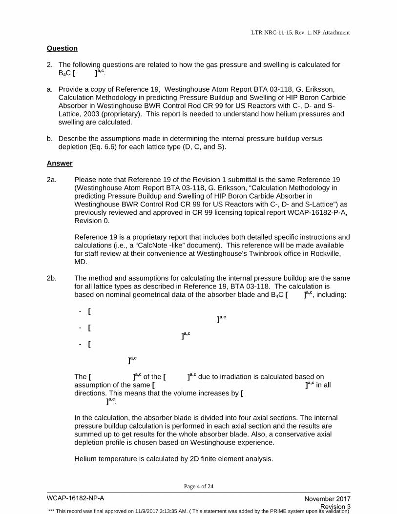
LTR-NRC-11-15, Rev. 1, NP-Attachment
Page 4 of 24
Question 2. The following questions are related to how the gas pressure and swelling is calculated for
B4C [ ]a,c. a. Provide a copy of Reference 19, Westinghouse Atom Report BTA 03-118, G. Eriksson,
Calculation Methodology in predicting Pressure Buildup and Swelling of HIP Boron Carbide Absorber in Westinghouse BWR Control Rod CR 99 for US Reactors with C-, D- and S-Lattice, 2003 (proprietary). This report is needed to understand how helium pressures and swelling are calculated.
b. Describe the assumptions made in determining the internal pressure buildup versus
depletion (Eq. 6.6) for each lattice type (D, C, and S). Answer 2a. Please note that Reference 19 of the Revision 1 submittal is the same Reference 19
(Westinghouse Atom Report BTA 03-118, G. Eriksson, “Calculation Methodology in predicting Pressure Buildup and Swelling of HIP Boron Carbide Absorber in Westinghouse BWR Control Rod CR 99 for US Reactors with C-, D- and S-Lattice”) as previously reviewed and approved in CR 99 licensing topical report WCAP-16182-P-A, Revision 0.
Reference 19 is a proprietary report that includes both detailed specific instructions and
calculations (i.e., a “CalcNote -like” document). This reference will be made available for staff review at their convenience at Westinghouse's Twinbrook office in Rockville, MD.
2b. The method and assumptions for calculating the internal pressure buildup are the same
for all lattice types as described in Reference 19, BTA 03-118. The calculation is based on nominal geometrical data of the absorber blade and B4C [ ]a,c, including:
- [ ]a,c
- [ ]a,c
- [ ]a,c
The [ ]a,c of the [ ]a,c due to irradiation is calculated based on assumption of the same [ ]a,c in all directions. This means that the volume increases by [ ]a,c. In the calculation, the absorber blade is divided into four axial sections. The internal pressure buildup calculation is performed in each axial section and the results are summed up to get results for the whole absorber blade. Also, a conservative axial depletion profile is chosen based on Westinghouse experience. Helium temperature is calculated by 2D finite element analysis.
WCAP-16182-NP-A____________________________________________________________________________________
November 2017 Revision 3
*** This record was final approved on 11/9/2017 3:13:35 AM. ( This statement was added by the PRIME system upon its validation)
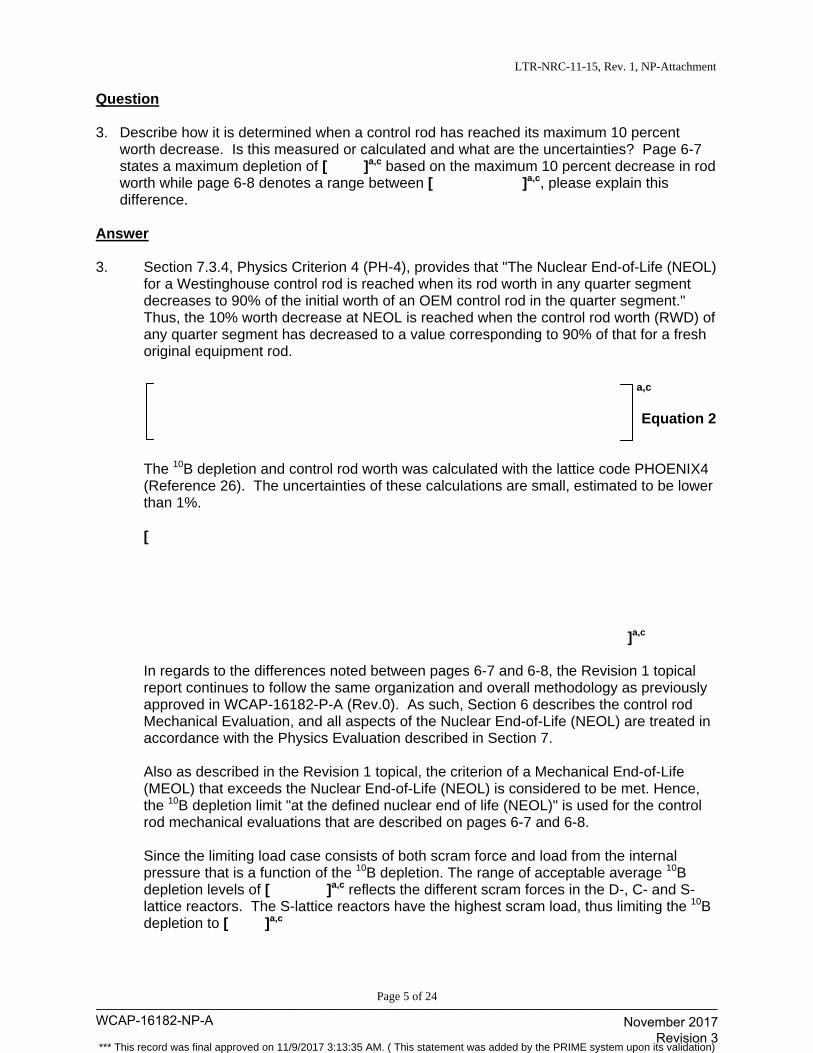
LTR-NRC-11-15, Rev. 1, NP-Attachment
Page 5 of 24
Question 3. Describe how it is determined when a control rod has reached its maximum 10 percent
worth decrease. Is this measured or calculated and what are the uncertainties? Page 6-7 states a maximum depletion of [ ]a,c based on the maximum 10 percent decrease in rod worth while page 6-8 denotes a range between [ ]a,c, please explain this difference.
Answer 3. Section 7.3.4, Physics Criterion 4 (PH-4), provides that "The Nuclear End-of-Life (NEOL)
for a Westinghouse control rod is reached when its rod worth in any quarter segment decreases to 90% of the initial worth of an OEM control rod in the quarter segment." Thus, the 10% worth decrease at NEOL is reached when the control rod worth (RWD) of any quarter segment has decreased to a value corresponding to 90% of that for a fresh original equipment rod.
Equation 2 The 10B depletion and control rod worth was calculated with the lattice code PHOENIX4 (Reference 26). The uncertainties of these calculations are small, estimated to be lower than 1%. [ ]a,c In regards to the differences noted between pages 6-7 and 6-8, the Revision 1 topical report continues to follow the same organization and overall methodology as previously approved in WCAP-16182-P-A (Rev.0). As such, Section 6 describes the control rod Mechanical Evaluation, and all aspects of the Nuclear End-of-Life (NEOL) are treated in accordance with the Physics Evaluation described in Section 7. Also as described in the Revision 1 topical, the criterion of a Mechanical End-of-Life (MEOL) that exceeds the Nuclear End-of-Life (NEOL) is considered to be met. Hence, the 10B depletion limit "at the defined nuclear end of life (NEOL)" is used for the control rod mechanical evaluations that are described on pages 6-7 and 6-8. Since the limiting load case consists of both scram force and load from the internal pressure that is a function of the 10B depletion. The range of acceptable average 10B depletion levels of [ ]a,c reflects the different scram forces in the D-, C- and S-lattice reactors. The S-lattice reactors have the highest scram load, thus limiting the 10B depletion to [ ]a,c
a,c
WCAP-16182-NP-A____________________________________________________________________________________
November 2017 Revision 3
*** This record was final approved on 11/9/2017 3:13:35 AM. ( This statement was added by the PRIME system upon its validation)
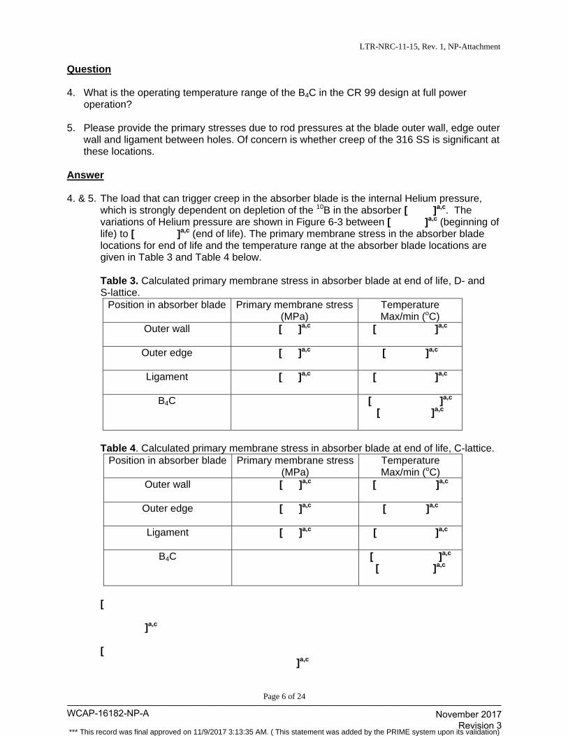
LTR-NRC-11-15, Rev. 1, NP-Attachment
Page 6 of 24
Question 4. What is the operating temperature range of the B4C in the CR 99 design at full power
operation? 5. Please provide the primary stresses due to rod pressures at the blade outer wall, edge outer
wall and ligament between holes. Of concern is whether creep of the 316 SS is significant at these locations.
Answer 4. & 5. The load that can trigger creep in the absorber blade is the internal Helium pressure,
which is strongly dependent on depletion of the 10B in the absorber [ ]a,c. The variations of Helium pressure are shown in Figure 6-3 between [ ]a,c (beginning of life) to [ ]a,c (end of life). The primary membrane stress in the absorber blade locations for end of life and the temperature range at the absorber blade locations are given in Table 3 and Table 4 below.
Table 3. Calculated primary membrane stress in absorber blade at end of life, D- and S-lattice.
Position in absorber blade Primary membrane stress(MPa)
Temperature Max/min (oC)
Outer wall
[ ]a,c [ ]a,c
Outer edge
[ ]a,c [ ]a,c
Ligament
[ ]a,c [ ]a,c
B4C
[ ]a,c [ ]a,c
Table 4. Calculated primary membrane stress in absorber blade at end of life, C-lattice.
Position in absorber blade Primary membrane stress(MPa)
Temperature Max/min (oC)
Outer wall
[ ]a,c [ ]a,c
Outer edge
[ ]a,c [ ]a,c
Ligament
[ ]a,c [ ]a,c
B4C
[ ]a,c [ ]a,c
[ ]a,c
[ ]a,c
WCAP-16182-NP-A____________________________________________________________________________________
November 2017 Revision 3
*** This record was final approved on 11/9/2017 3:13:35 AM. ( This statement was added by the PRIME system upon its validation)
LTR-NRC-11-15, Rev. 1, NP-Attachment
Page 7 of 24
The measured long term steady state creep data for AISI 316L at a temperature of 550oC and higher are given in "Creep of the austenitic steel AISI 316L – Experiments and Models -", M. Rieth et. al. Forschongszentrum Karlsruhe GmbH, Karlsruhe (ISSN 09047-8620, urn:nbn:de:0005-070657). For the calculated stresses in the absorber blade, the creep strain rate is lower than 10-9/hr at temperature 550oC. The creep rate is strongly temperature dependent and is therefore of no concern.
WCAP-16182-NP-A____________________________________________________________________________________
November 2017 Revision 3
*** This record was final approved on 11/9/2017 3:13:35 AM. ( This statement was added by the PRIME system upon its validation)
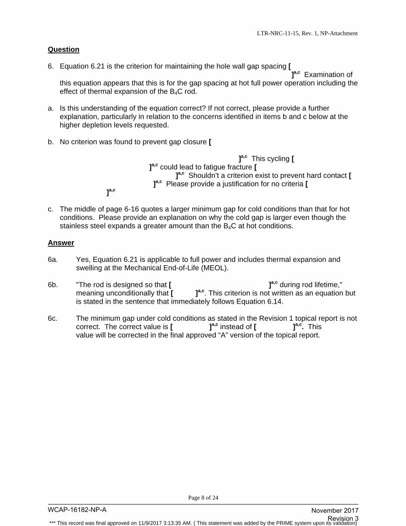
LTR-NRC-11-15, Rev. 1, NP-Attachment
Page 8 of 24
Question 6. Equation 6.21 is the criterion for maintaining the hole wall gap spacing [ ]a,c Examination of
this equation appears that this is for the gap spacing at hot full power operation including the effect of thermal expansion of the B4C rod.
a. Is this understanding of the equation correct? If not correct, please provide a further
explanation, particularly in relation to the concerns identified in items b and c below at the higher depletion levels requested.
b. No criterion was found to prevent gap closure [ ]a,c This cycling [ ]a,c could lead to fatigue fracture [ ]a,c Shouldn’t a criterion exist to prevent hard contact [ ]a,c Please provide a justification for no criteria [ ]a,c
c. The middle of page 6-16 quotes a larger minimum gap for cold conditions than that for hot
conditions. Please provide an explanation on why the cold gap is larger even though the stainless steel expands a greater amount than the B4C at hot conditions.
Answer 6a. Yes, Equation 6.21 is applicable to full power and includes thermal expansion and
swelling at the Mechanical End-of-Life (MEOL). 6b. "The rod is designed so that [ ]a,c during rod lifetime,"
meaning unconditionally that [ ]a,c. This criterion is not written as an equation but is stated in the sentence that immediately follows Equation 6.14.
6c. The minimum gap under cold conditions as stated in the Revision 1 topical report is not
correct. The correct value is [ ]a,c instead of [ ]a,c. This value will be corrected in the final approved “A” version of the topical report.
WCAP-16182-NP-A____________________________________________________________________________________
November 2017 Revision 3
*** This record was final approved on 11/9/2017 3:13:35 AM. ( This statement was added by the PRIME system upon its validation)
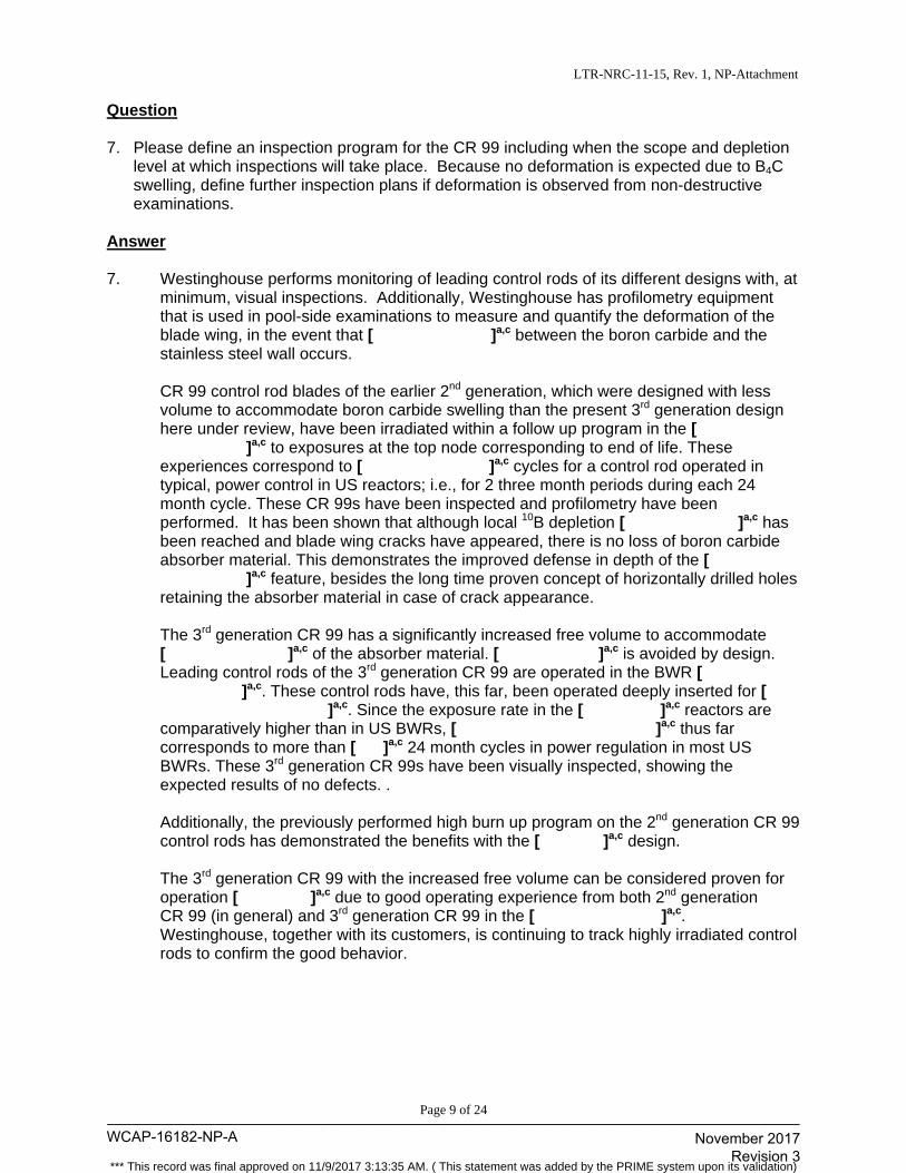
LTR-NRC-11-15, Rev. 1, NP-Attachment
Page 9 of 24
Question 7. Please define an inspection program for the CR 99 including when the scope and depletion
level at which inspections will take place. Because no deformation is expected due to B4C swelling, define further inspection plans if deformation is observed from non-destructive examinations.
Answer 7. Westinghouse performs monitoring of leading control rods of its different designs with, at
minimum, visual inspections. Additionally, Westinghouse has profilometry equipment that is used in pool-side examinations to measure and quantify the deformation of the blade wing, in the event that [ ]a,c between the boron carbide and the stainless steel wall occurs. CR 99 control rod blades of the earlier 2nd generation, which were designed with less volume to accommodate boron carbide swelling than the present 3rd generation design here under review, have been irradiated within a follow up program in the [
]a,c to exposures at the top node corresponding to end of life. These experiences correspond to [ ]a,c cycles for a control rod operated in typical, power control in US reactors; i.e., for 2 three month periods during each 24 month cycle. These CR 99s have been inspected and profilometry have been performed. It has been shown that although local 10B depletion [ ]a,c has been reached and blade wing cracks have appeared, there is no loss of boron carbide absorber material. This demonstrates the improved defense in depth of the [
]a,c feature, besides the long time proven concept of horizontally drilled holes retaining the absorber material in case of crack appearance. The 3rd generation CR 99 has a significantly increased free volume to accommodate
[ ]a,c of the absorber material. [ ]a,c is avoided by design. Leading control rods of the 3rd generation CR 99 are operated in the BWR [
]a,c. These control rods have, this far, been operated deeply inserted for [ ]a,c. Since the exposure rate in the [ ]a,c reactors are
comparatively higher than in US BWRs, [ ]a,c thus far corresponds to more than [ ]a,c 24 month cycles in power regulation in most US BWRs. These 3rd generation CR 99s have been visually inspected, showing the expected results of no defects. . Additionally, the previously performed high burn up program on the 2nd generation CR 99 control rods has demonstrated the benefits with the [ ]a,c design.
The 3rd generation CR 99 with the increased free volume can be considered proven for
operation [ ]a,c due to good operating experience from both 2nd generation CR 99 (in general) and 3rd generation CR 99 in the [ ]a,c. Westinghouse, together with its customers, is continuing to track highly irradiated control rods to confirm the good behavior.
WCAP-16182-NP-A____________________________________________________________________________________
November 2017 Revision 3
*** This record was final approved on 11/9/2017 3:13:35 AM. ( This statement was added by the PRIME system upon its validation)
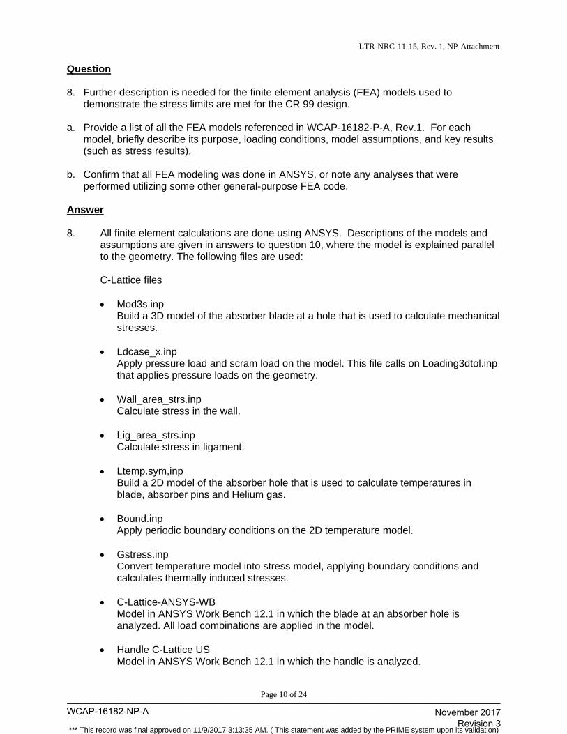
LTR-NRC-11-15, Rev. 1, NP-Attachment
Page 10 of 24
Question 8. Further description is needed for the finite element analysis (FEA) models used to
demonstrate the stress limits are met for the CR 99 design. a. Provide a list of all the FEA models referenced in WCAP-16182-P-A, Rev.1. For each
model, briefly describe its purpose, loading conditions, model assumptions, and key results (such as stress results).
b. Confirm that all FEA modeling was done in ANSYS, or note any analyses that were
performed utilizing some other general-purpose FEA code. Answer 8. All finite element calculations are done using ANSYS. Descriptions of the models and
assumptions are given in answers to question 10, where the model is explained parallel to the geometry. The following files are used: C-Lattice files
Mod3s.inp
Build a 3D model of the absorber blade at a hole that is used to calculate mechanical stresses.
Ldcase_x.inp Apply pressure load and scram load on the model. This file calls on Loading3dtol.inp that applies pressure loads on the geometry.
Wall_area_strs.inp Calculate stress in the wall.
Lig_area_strs.inp Calculate stress in ligament.
Ltemp.sym,inp Build a 2D model of the absorber hole that is used to calculate temperatures in blade, absorber pins and Helium gas.
Bound.inp Apply periodic boundary conditions on the 2D temperature model.
Gstress.inp Convert temperature model into stress model, applying boundary conditions and calculates thermally induced stresses.
C-Lattice-ANSYS-WB Model in ANSYS Work Bench 12.1 in which the blade at an absorber hole is analyzed. All load combinations are applied in the model.
Handle C-Lattice US Model in ANSYS Work Bench 12.1 in which the handle is analyzed.
WCAP-16182-NP-A____________________________________________________________________________________
November 2017 Revision 3
*** This record was final approved on 11/9/2017 3:13:35 AM. ( This statement was added by the PRIME system upon its validation)
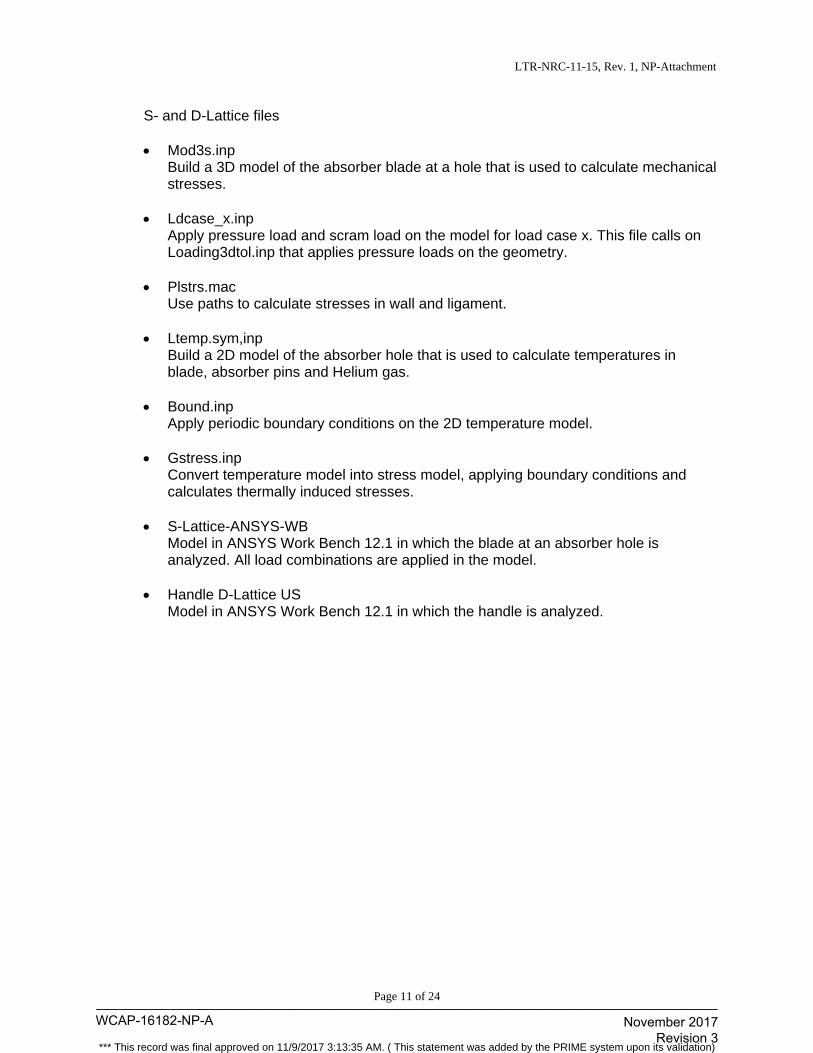
LTR-NRC-11-15, Rev. 1, NP-Attachment
Page 11 of 24
S- and D-Lattice files Mod3s.inp
Build a 3D model of the absorber blade at a hole that is used to calculate mechanical stresses.
Ldcase_x.inp Apply pressure load and scram load on the model for load case x. This file calls on Loading3dtol.inp that applies pressure loads on the geometry.
Plstrs.mac Use paths to calculate stresses in wall and ligament.
Ltemp.sym,inp Build a 2D model of the absorber hole that is used to calculate temperatures in blade, absorber pins and Helium gas.
Bound.inp Apply periodic boundary conditions on the 2D temperature model.
Gstress.inp Convert temperature model into stress model, applying boundary conditions and calculates thermally induced stresses.
S-Lattice-ANSYS-WB Model in ANSYS Work Bench 12.1 in which the blade at an absorber hole is analyzed. All load combinations are applied in the model.
Handle D-Lattice US Model in ANSYS Work Bench 12.1 in which the handle is analyzed.
WCAP-16182-NP-A____________________________________________________________________________________
November 2017 Revision 3
*** This record was final approved on 11/9/2017 3:13:35 AM. ( This statement was added by the PRIME system upon its validation)
LTR-NRC-11-15, Rev. 1, NP-Attachment
Page 12 of 24
Question 9. Provide a complete set of input and output files for each of the FEA models. As an
alternative to providing input and output files for review in a written response, an on-site audit of the FEA calculations with full interactive access to the models and results for the reviewers could also achieve the same objective.
Answer 9. Westinghouse will make input and output files of the FEA analysis available for NRC
staff review as part of an audit.
WCAP-16182-NP-A____________________________________________________________________________________
November 2017 Revision 3
*** This record was final approved on 11/9/2017 3:13:35 AM. ( This statement was added by the PRIME system upon its validation)
LTR-NRC-11-15, Rev. 1, NP-Attachment
Page 13 of 24
Question 10. The geometry of the CR 99 and the FEA modeling are not clear in the submittal. a. Provide detailed drawings or sketches that describe the geometry of the control blade
structure. The reviewers request drawings with enough geometry and annotation to explain the basic shape of the stainless steel components, including the geometry of the control rod blade central axis and control blade wing connection regions. One specific request is a horizontal cross section view through a control blade wing, with major dimensions and radii noted that are important in the stress analysis. Also, provide drawings or sketches that clarify the size, location, and orientation of the B4C absorber relative to the control blade geometry.
b. Explain and justify the symmetry assumptions and the particular geometry used in the FEA
models. Figure 6-4 appears to be a half-symmetry model of a single absorber hole, sectioned horizontally through a control blade wing. However, the original document (WCAP-16182, Rev. 0) indicates that [
]a,c so it is not clear which absorber hole was chosen for analysis or why it was chosen. [
]a,c
Answer 10a. Shown below are examples of CR 99 outline drawings, detailed sketches of a horizontal
cross section, and the corresponding dimensions for CR 99 control rods with 7 mm and 8 mm blade wing thickness.
WCAP-16182-NP-A____________________________________________________________________________________
November 2017 Revision 3
*** This record was final approved on 11/9/2017 3:13:35 AM. ( This statement was added by the PRIME system upon its validation)
LTR-NRC-11-15, Rev. 1, NP-Attachment
Page 14 of 24
Figure 3. Outline drawing 7 mm blade wing thickness
Figure 4. Horizontal cross section 7 mm blade wing thickness
Table 5. Dimensions for 7 mm blade wing thickness
a,c
a,c
a,c
WCAP-16182-NP-A____________________________________________________________________________________
November 2017 Revision 3
*** This record was final approved on 11/9/2017 3:13:35 AM. ( This statement was added by the PRIME system upon its validation)

LTR-NRC-11-15, Rev. 1, NP-Attachment
Page 15 of 24
Figure 5. Outline drawing 8 mm blade wing thickness
Figure 6. Horizontal cross section 8 mm blade wing thickness
Table 6. Dimensions for 8 mm blade wing thickness a,c
a,c
a,c
WCAP-16182-NP-A____________________________________________________________________________________
November 2017 Revision 3
*** This record was final approved on 11/9/2017 3:13:35 AM. ( This statement was added by the PRIME system upon its validation)
LTR-NRC-11-15, Rev. 1, NP-Attachment
Page 16 of 24
10b. Model of absorber blade: The load on the absorber blade consists of two types:
1. Internal Helium pressure, which has the same magnitude in all holes for the absorber [ ]a,c (communicating pressure vessel), and
2. Scram forces, which are assumed to result in constant acceleration in the control rod. This assumption makes it possible to scale the scram force in a cross section of the blade as a function of the total mass above the cross section.
The definition of these loads results in the conclusion that for a constant hole depth, the critical cross section is the one with the largest mass above the cross section. Any contribution to the cross section area by the shoulders at the central axis of the control rod is neglected. If the number of hole depths in the blade layout are X, X number of possible critical cross sections can be identified. Every possible critical cross section is investigated by estimation of the primary membrane stress caused by internal Helium pressure and scram force. This estimation is calculated by:
Equation 3 Where PHe is the internal Helium pressure, D the diameter of the hole, L the hole length and Ai the area of the cross section i. Fscram,i is calculated by:
Equation 4
Where F is the specified scram force at the coupling, M the mass of the control rod and Mi the mass above cross section i. The cross section with largest Pm is identified as the critical cross section. This cross section is modeled and analyzed with the finite element system ANSYS. Conservative geometry assumptions are used in the finite element model. Tolerances are chosen so that a minimum cross sectional area is used, with minimum blade thickness, maximum hole diameter and length, and maximum shoulder height. Minimum specified ligament thickness is used in the finite element model and the cross section through the ligament is constrained to constant axial deformation. The cross section through the absorber hole is constrained to zero axial deformation. These constraints are used because the critical load combination is scram force superimposed to internal Helium pressure. Geometry of the CR 99 S-Lattice control rod: Figure 7 and Figure 8 are shown in order to explain the finite element model used in the calculations of the absorber blade.
a,c
a,c
WCAP-16182-NP-A____________________________________________________________________________________
November 2017 Revision 3
*** This record was final approved on 11/9/2017 3:13:35 AM. ( This statement was added by the PRIME system upon its validation)
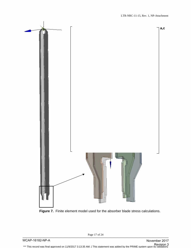
LTR-NRC-11-15, Rev. 1, NP-Attachment
Page 17 of 24
Figure 7. Finite element model used for the absorber blade stress calculations.
a,c
WCAP-16182-NP-A____________________________________________________________________________________
November 2017 Revision 3
*** This record was final approved on 11/9/2017 3:13:35 AM. ( This statement was added by the PRIME system upon its validation)
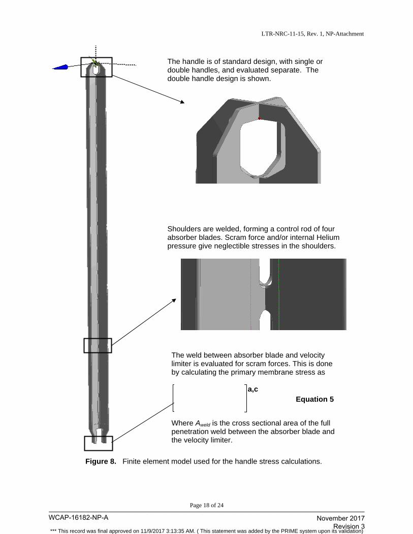
LTR-NRC-11-15, Rev. 1, NP-Attachment
Page 18 of 24
Figure 8. Finite element model used for the handle stress calculations.
Shoulders are welded, forming a control rod of four absorber blades. Scram force and/or internal Helium pressure give neglectible stresses in the shoulders.
The handle is of standard design, with single or double handles, and evaluated separate. The double handle design is shown.
The weld between absorber blade and velocity limiter is evaluated for scram forces. This is done by calculating the primary membrane stress as
Equation 5
Where Aweld is the cross sectional area of the full penetration weld between the absorber blade and the velocity limiter.
a,c
WCAP-16182-NP-A____________________________________________________________________________________
November 2017 Revision 3
*** This record was final approved on 11/9/2017 3:13:35 AM. ( This statement was added by the PRIME system upon its validation)
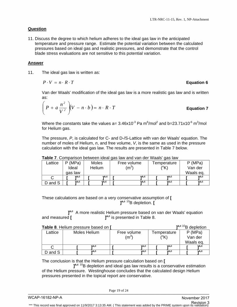
LTR-NRC-11-15, Rev. 1, NP-Attachment
Page 19 of 24
Question 11. Discuss the degree to which helium adheres to the ideal gas law in the anticipated
temperature and pressure range. Estimate the potential variation between the calculated pressures based on ideal gas and realistic pressures, and demonstrate that the control blade stress evaluations are not sensitive to this potential variation.
Answer
11. The ideal gas law is written as:
TRnVP Equation 6 Van der Waals' modification of the ideal gas law is a more realistic gas law and is written
as:
TRnbnVV
naP 2
2
Equation 7
Where the constants take the values a= 3.46x10⁻³ Pa m6/mol2 and b=23.71x10⁻⁶ m3/mol
for Helium gas. The pressure, P, is calculated for C- and D-/S-Lattice with van der Waals' equation. The number of moles of Helium, n, and free volume, V, is the same as used in the pressure calculation with the ideal gas law. The results are presented in Table 7 below. Table 7. Comparison between ideal gas law and van der Waals' gas law
Lattice P (MPa) Ideal
gas law
Moles Helium
Free volume (m3)
Temperature (oK)
P (MPa) Van der
Waals eq. C [ ]a,c [ ]a,c [ ]a,c [ ]a,c [ ]a,c
D and S [ ]a,c [ ]a,c [ ]a,c [ ]a,c [ ]a,c These calculations are based on a very conservative assumption of [ ]a,c 10B depletion. [ ]a,c A more realistic Helium pressure based on van der Waals' equation
and measured [ ]a,c is presented in Table 8. Table 8. Helium pressure based on [ ]a,c 10B depletion
Lattice Moles Helium Free volume (m3)
Temperature (oK)
P (MPa) Van der
Waals eq. C [ ]a,c [ ]a,c [ ]a,c [ ]a,c
D and S [ ]a,c [ ]a,c [ ]a,c [ ]a,c
The conclusion is that the Helium pressure calculation based on [ ]a,c 10B depletion and ideal gas law results is a conservative estimation of the Helium pressure. Westinghouse concludes that the calculated design Helium pressures presented in the topical report are conservative.
WCAP-16182-NP-A____________________________________________________________________________________
November 2017 Revision 3
*** This record was final approved on 11/9/2017 3:13:35 AM. ( This statement was added by the PRIME system upon its validation)
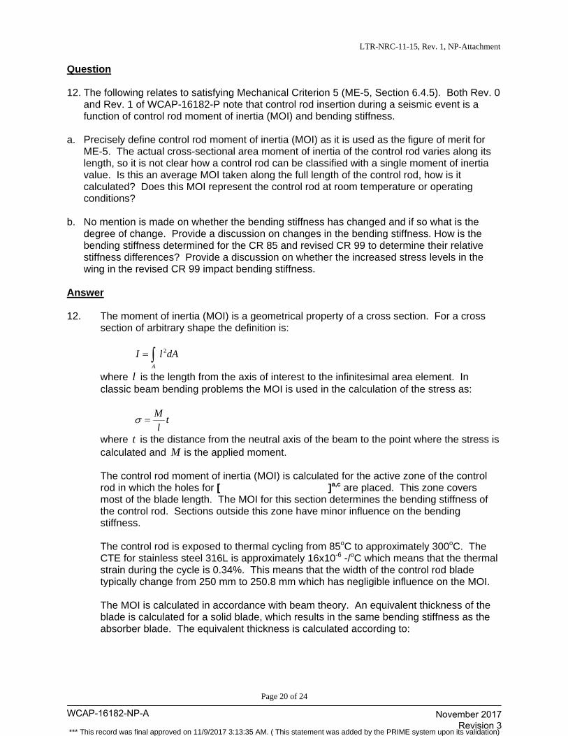
LTR-NRC-11-15, Rev. 1, NP-Attachment
Page 20 of 24
Question
12. The following relates to satisfying Mechanical Criterion 5 (ME-5, Section 6.4.5). Both Rev. 0 and Rev. 1 of WCAP-16182-P note that control rod insertion during a seismic event is a function of control rod moment of inertia (MOI) and bending stiffness.
a. Precisely define control rod moment of inertia (MOI) as it is used as the figure of merit for
ME-5. The actual cross-sectional area moment of inertia of the control rod varies along its length, so it is not clear how a control rod can be classified with a single moment of inertia value. Is this an average MOI taken along the full length of the control rod, how is it calculated? Does this MOI represent the control rod at room temperature or operating conditions?
b. No mention is made on whether the bending stiffness has changed and if so what is the
degree of change. Provide a discussion on changes in the bending stiffness. How is the bending stiffness determined for the CR 85 and revised CR 99 to determine their relative stiffness differences? Provide a discussion on whether the increased stress levels in the wing in the revised CR 99 impact bending stiffness.
Answer
12. The moment of inertia (MOI) is a geometrical property of a cross section. For a cross
section of arbitrary shape the definition is:
dAlIA 2
where l is the length from the axis of interest to the infinitesimal area element. In classic beam bending problems the MOI is used in the calculation of the stress as:
tl
M
where t is the distance from the neutral axis of the beam to the point where the stress is calculated and M is the applied moment.
The control rod moment of inertia (MOI) is calculated for the active zone of the control rod in which the holes for [ ]a,c are placed. This zone covers most of the blade length. The MOI for this section determines the bending stiffness of the control rod. Sections outside this zone have minor influence on the bending stiffness. The control rod is exposed to thermal cycling from 85oC to approximately 300oC. The CTE for stainless steel 316L is approximately 16x10-6 -/oC which means that the thermal strain during the cycle is 0.34%. This means that the width of the control rod blade typically change from 250 mm to 250.8 mm which has negligible influence on the MOI. The MOI is calculated in accordance with beam theory. An equivalent thickness of the blade is calculated for a solid blade, which results in the same bending stiffness as the absorber blade. The equivalent thickness is calculated according to:
WCAP-16182-NP-A____________________________________________________________________________________
November 2017 Revision 3
*** This record was final approved on 11/9/2017 3:13:35 AM. ( This statement was added by the PRIME system upon its validation)
LTR-NRC-11-15, Rev. 1, NP-Attachment
Page 21 of 24
Equation 8
Equation 9
t Absorber blade thickness d diameter of hole p pitch between holes teq equivalent thickness C Parameter that is calibrated against test results A three point bending test of Japanese control rods very similar to C-, D- and S-Lattice is used to calibrate the parameter C. This calculation is performed for the reference control rods CR 85 and the control rods for C-, D- and S-Lattice. The calculated MOI depends on the layout of the control rod, but typical results are given in Table 9 below. Table 9. Typical calculated MOI for CR 99 and comparison with reference control rod CR 85.
Lattice type CR 99 MOI CR 85 MOI C- Lattice [ ]a,c [ ]a,c D-Lattice [ ]a,c [ ]a,c S-Lattice [ ]a,c [ ]a,c
The increased stress level in CR 99 control rods depends mainly on higher allowed Helium pressure. The influence of Helium pressure on bending stiffness is low and therefore negligible.
a,c
a,c
WCAP-16182-NP-A____________________________________________________________________________________
November 2017 Revision 3
*** This record was final approved on 11/9/2017 3:13:35 AM. ( This statement was added by the PRIME system upon its validation)
LTR-NRC-11-15, Rev. 1, NP-Attachment
Page 22 of 24
Question
13. For Operational Criteria 2, describe the range of acceptable deviation from the nominal weight. Also describe the basis for this range.
Answer
13. The weight of Westinghouse Sweden Engineering control rods are limited to the same
maximum level as the OEM (Original Equipment Manufacturer) control rods. Maximum weights are defined for the control rods to the D-, C-, and S-lattice reactors.
The nominal weight is due to the design with blade wings in solid stainless steel close to
the max allowed weight. The nominal weight differs slightly relative to the maximum weight for the different control rods. The highest difference corresponds to 3.5% of the nominal weight. The minimum weight, which is basically defined by the geometrical dimensional requirements, is related to the nominal weight by a maximum difference of 2.5%. Thus the range of acceptable deviation from the nominal weight is +3.5% to
-2.5%.
WCAP-16182-NP-A____________________________________________________________________________________
November 2017 Revision 3
*** This record was final approved on 11/9/2017 3:13:35 AM. ( This statement was added by the PRIME system upon its validation)
LTR-NRC-11-15, Rev. 1, NP-Attachment
Page 23 of 24
Question
14. For Operational Criteria 1, 3, 4, 6, and 7, explain in more detail how the CR 99 control blade
relates to the extensive database of experience. For example, OP-6 states “Extensive database of experience has shown that the design meets this criterion, i.e., scram times for Westinghouse control rods are within the experience base (and meet Technical Specification times) of the reactors into which they have been installed.” It is assumed that this statement is not referring to direct experience with CR 99 C-, D-, and S- lattice blades, but rather the CR 99 blades are comparable to other successful designs that comprise the extensive database. Provide a discussion of the differences in the most relevant past designs with CR 99 along with the number of blades irradiated, their maximum length of time in-reactor, and depletion level.
Answer 14. The first Westinghouse BWR control rods were installed in US BWRs in the mid-1980s.
Many of these control rods are still in operation thus demonstrating the performance and compatibility of these designs for over 25 years.
Since then more than 1500 Westinghouse BWR control rods have been operated in US
reactors of D-, C- and S-lattice types. Furthermore, another 200 Westinghouse BWR control rods have been operated in reactors built by GE outside of the US. All these control rods, irrespective of type CR 99, CR 82M-1, etc., have had the same outer dimensions and geometry within the groups of D-, C- and S-lattice reactors. The difference between the types is mainly defined by the cross sectional outline of the absorber material inside the blade wings. Thus for the reviewed CR 99, compatibility with operation in GE BWR reactors is proven by the large amount of successfully operated control rods.
WCAP-16182-NP-A____________________________________________________________________________________
November 2017 Revision 3
*** This record was final approved on 11/9/2017 3:13:35 AM. ( This statement was added by the PRIME system upon its validation)
LTR-NRC-11-15, Rev. 1, NP-Attachment
Page 24 of 24
Question 15. Justify the new design stress limit defined in Section 6.3.1, considering the change to [ ]a,c
This appears to be a less conservative stress limit than the one based [ ]a,c and previously
approved in WCAP-16182-P-A, Rev. 0. Explain the need for two separate definitions of Sm in this document and explain how the two are implemented.
Answer 15. The [ ]a,c (Section 6.3.2 in WCAP-16182-P-A, Revision 1) is intended to be
used for hand calculation of areas where Westinghouse knows from experience that the margin is large. Hand calculation is less accurate than results from finite element calculation and Westinghouse therefore uses larger margins in those calculations. For consistency with previous design requirements, the limits previously approved in Revision 0 of the CR 99 licensing topical report are also retained as an alternative that may be used with the more conservative maximum shear stress theory (Tresca). The idea being that the current licensing analyses of various control rod handle designs and the standard part of the control rod below the absorber zone should remain valid. The [ ]a,c (Section 6.3.1 in WCAP-16182-P-A, Revision 1) is intended to be used in combination with finite element calculations. This criterion is written based on knowledge of results from collapse analysis of the absorber blade according to [ ]a,c and the [
]a,c. [ ]a,c and defines the allowable stress for primary membrane stress to:
Equation 10
[ ]a,c The proposed definition of [ ]a,c limit in
WCAP-16182-P-A, Revision 1, is more conservative than [ ]a,c. Collapse analyses of the absorber blade based on models similar to the model shown in WCAP-16182-P-A, Revision 1, Figure 6-4 typically show that a load combination of internal pressure and scram loads results in margin similar to that predicted by the proposed [ ]a,c. These collapse analyses are based on
[ ]a,c, which is known to agree well with observed plastic behavior of steels.
a,c
WCAP-16182-NP-A____________________________________________________________________________________
November 2017 Revision 3
*** This record was final approved on 11/9/2017 3:13:35 AM. ( This statement was added by the PRIME system upon its validation)
(fJ) Westinghouse
U.S. Nuclear Regulatory Commission Document Control Desk 11555 Rockville Pike Rockville, MD 20852
Westinghouse Electric Company Nuclear Services 1 000 Westinghouse Drive Cranberry Township, Pennsylvania 16066 USA
Direct tel: (412) 374-4643 Direct fax: (724) 720-0754
e-mail: [email protected]
LTR-NRC-12-48
June 21,2012
Subject: Response to the NRC's Request for Additional Information on WCAP-16182-P-A, Revision 1, "Westinghouse BWR Control Rod CR 99 Licensing Report- Update to Mechanical Design Limits" (Proprietary/Non-Proprietary)
Enclosed are the proprietary and non-proprietary versions of, "Response to the NRC's Request for Additional Information on WCAP-16182-P-A, Revision 1, 'Westinghouse BWR Control Rod CR 99 Licensing Report- Update to Mechanical Design Limits.'"
Also enclosed is:
1. One (1) copy of the Application for Withholding Proprietary Information from Public Disclosure, A W-12-3502 (Non-Proprietary), with Proprietary Infotmation Notice and Copyright Notice.
2. One (1) copy of Affidavit (Non-Proprietary).
This submittal contains proprietary information of Westinghouse Electric Company LLC. In conformance with the requirements of 10 CFR Section 2.390, as amended, of the Commission's regulations, we are enclosing with this submittal an Application for Withholding Proprietary Information from Public Disclosure and an affidavit. The affidavit sets forth the basis on which the information identified as proprietary may be withheld from public disclosure by the Commission.
Conespondence with respect to the proprietary aspects of the application for withholding or the Westinghouse affidavit should reference AW-12-3502, and should be addressed to J. A. Gresham, Manager, Regulatory Compliance, Westinghouse Electric Company, Suite 428, 1000 Westinghouse Drive, Cranberry Township, Pennsylvania 16066.
Enclosures
cc: E. Lenning A. Mendiola
Very truly yours,
~~~ J. A. Gresham, Manager Regulatory Compliance
WCAP-16182-NP-A____________________________________________________________________________________
November 2017 Revision 3
*** This record was final approved on 11/9/2017 3:13:35 AM. ( This statement was added by the PRIME system upon its validation)
WCAP-16182-NP-A____________________________________________________________________________________
November 2017 Revision 3
*** This record was final approved on 11/9/2017 3:13:35 AM. ( This statement was added by the PRIME system upon its validation)
WCAP-16182-NP-A____________________________________________________________________________________
November 2017 Revision 3
*** This record was final approved on 11/9/2017 3:13:35 AM. ( This statement was added by the PRIME system upon its validation)

AW-12-3502
2
(1) I am Manager, ABWR Licensing, in Nuclear Services, Westinghouse Electric Company LLC
(Westinghouse), and as such, I have been specifically delegated the function of reviewing the
proprietary information sought to be withheld from public disclosure in connection with nuclear
power plant licensing and rule making proceedings, and am authorized to apply for its
withholding on behalf of Westinghouse.
(2) I am making this Affidavit in conformance with the provisions of 10 CFR Section 2.390 of the
Commission's regulations and in conjunction with the Westinghouse Application for Withholding
Proprietary Information from Public Disclosure accompanying this Affidavit.
(3) I have personal knowledge of the criteria and procedures utilized by Westinghouse in designating
information as a trade secret, privileged or as confidential commercial or financial information.
(4) Pursuant to the provisions of paragraph (b)(4) of Section 2.390 of the Commission's regulations,
the following is furnished for consideration by the Commission in determining whether the
information sought to be withheld from public disclosure should be withheld.
(i) The information sought to be withheld from public disclosure is owned and has been held
in confidence by Westinghouse.
(ii) The information is of a type customarily held in confidence by Westinghouse and not
customarily disclosed to the public. Westinghouse has a rational basis for determining
the types of information customarily held in confidence by it and, in that connection,
utilizes a system to determine when and whether to hold certain types of information in
confidence. The application of that system and the substance of that system constitutes
Westinghouse policy and provides the rational basis required.
Under that system, information is held in confidence if it falls in one or more of several
types, the release of which might result in the loss of an existing or potential competitive
advantage, as follows:
(a) The information reveals the distinguishing aspects of a process (or component,
structure, tool, method, etc.) where prevention of its use by any of
WCAP-16182-NP-A____________________________________________________________________________________
November 2017 Revision 3
*** This record was final approved on 11/9/2017 3:13:35 AM. ( This statement was added by the PRIME system upon its validation)

AW-12-3502
3
Westinghouse’s competitors without license from Westinghouse constitutes a
competitive economic advantage over other companies.
(b) It consists of supporting data, including test data, relative to a process (or
component, structure, tool, method, etc.), the application of which data secures a
competitive economic advantage, e.g., by optimization or improved
marketability.
(c) Its use by a competitor would reduce his expenditure of resources or improve his
competitive position in the design, manufacture, shipment, installation, assurance
of quality, or licensing a similar product.
(d) It reveals cost or price information, production capacities, budget levels, or
commercial strategies of Westinghouse, its customers or suppliers.
(e) It reveals aspects of past, present, or future Westinghouse or customer funded
development plans and programs of potential commercial value to Westinghouse.
(f) It contains patentable ideas, for which patent protection may be desirable.
There are sound policy reasons behind the Westinghouse system which include the
following:
(a) The use of such information by Westinghouse gives Westinghouse a competitive
advantage over its competitors. It is, therefore, withheld from disclosure to
protect the Westinghouse competitive position.
(b) It is information that is marketable in many ways. The extent to which such
information is available to competitors diminishes the Westinghouse ability to
sell products and services involving the use of the information.
(c) Use by our competitor would put Westinghouse at a competitive disadvantage by
reducing his expenditure of resources at our expense.
WCAP-16182-NP-A____________________________________________________________________________________
November 2017 Revision 3
*** This record was final approved on 11/9/2017 3:13:35 AM. ( This statement was added by the PRIME system upon its validation)

AW-12-3502
4
(d) Each component of proprietary information pertinent to a particular competitive
advantage is potentially as valuable as the total competitive advantage. If
competitors acquire components of proprietary information, any one component
may be the key to the entire puzzle, thereby depriving Westinghouse of a
competitive advantage.
(e) Unrestricted disclosure would jeopardize the position of prominence of
Westinghouse in the world market, and thereby give a market advantage to the
competition of those countries.
(f) The Westinghouse capacity to invest corporate assets in research and
development depends upon the success in obtaining and maintaining a
competitive advantage.
(iii) The information is being transmitted to the Commission in confidence and, under the
provisions of 10 CFR Section 2.390, it is to be received in confidence by the
Commission.
(iv) The information sought to be protected is not available in public sources or available
information has not been previously employed in the same original manner or method to
the best of our knowledge and belief.
(v) The proprietary information sought to be withheld in this submittal is that which is
appropriately marked in LTR-NRC-12-48 P-Attachment, “Response to the NRC’s Request
for Additional Information on WCAP-16182-P-A, Revision 1, ‘Westinghouse BWR
Control Rod CR 99 Licensing Report - Update to Mechanical Design Limits’”
(Proprietary), for submittal to the Commission, being transmitted by Westinghouse letter,
LTR-NRC-12-48, and Application for Withholding Proprietary Information from Public
Disclosure, to the Document Control Desk. The proprietary information as submitted by
Westinghouse is that associated with Westinghouse’s request for NRC approval of
WCAP-16182-P-A, Revision 1, and may be used only for that purpose.
WCAP-16182-NP-A____________________________________________________________________________________
November 2017 Revision 3
*** This record was final approved on 11/9/2017 3:13:35 AM. ( This statement was added by the PRIME system upon its validation)
AW-12-3502
5
This information is part of that which will enable Westinghouse to:
(a) Obtain NRC approval of WCAP-16182-P-A, Revision 1, “Westinghouse BWR
Control Rod CR 99 Licensing Report - Update to Mechanical Design Limits.”
(b) Extend the mechanical life time of Westinghouse BWR control blades.
Further this information has substantial commercial value as follows:
(a) Westinghouse plans to sell the use of this information to its customers for the
purpose of assisting in obtaining license changes.
(b) The information requested to be withheld reveals the distinguishing aspects of a
methodology which was developed by Westinghouse.
Public disclosure of this proprietary information is likely to cause substantial harm to the
competitive position of Westinghouse because it would enhance the ability of
competitors to provide similar fuel design and licensing defense services for commercial
power reactors without commensurate expenses. Also, public disclosure of the
information would enable others to use the information to meet NRC requirements for
licensing documentation without purchasing the right to use the information.
The development of the technology described in part by the information is the result of
applying the results of many years of experience in an intensive Westinghouse effort and
the expenditure of a considerable sum of money.
In order for competitors of Westinghouse to duplicate this information, similar technical
programs would have to be performed and a significant manpower effort, having the
requisite talent and experience, would have to be expended.
Further the deponent sayeth not.
WCAP-16182-NP-A____________________________________________________________________________________
November 2017 Revision 3
*** This record was final approved on 11/9/2017 3:13:35 AM. ( This statement was added by the PRIME system upon its validation)
Proprietary Information Notice
Transmitted herewith are proprietary and/or non-proprietary versions of documents furnished to the NRC in connection with requests for generic and/or plant-specific review and approval. In order to conform to the requirements of 10 CFR 2.390 of the Commission's regulations concerning the protection of proprietary information so submitted to the NRC, the information which is proprietary in the proprietary versions is contained within brackets, and where the proprietary information has been deleted in the non-proprietary versions, only the brackets remain (the information that was contained within the brackets in the proprietary versions having been deleted). The justification for claiming the information so designated as proprietary is indicated in both versions by means of lower case letters (a) through (f) located as a superscript immediately following the brackets enclosing each item of information being identified as proprietary or in the margin opposite such information. These lower case letters refer to the types of information Westinghouse customarily holds in confidence identified in Sections (4)(ii)(a) through (4)(ii)(f) of the affidavit accompanying this transmittal pursuant to 10 CFR 2.390(b)(1).
Copyright Notice The reports transmitted herewith each bear a Westinghouse copyright notice. The NRC is permitted to make the number of copies of the information contained in these reports which are necessary for its internal use in connection with generic and plant-specific reviews and approvals as well as the issuance, denial, amendment, transfer, renewal, modification, suspension, revocation, or violation of a license, permit, order, or regulation subject to the requirements of 10 CFR 2.390 regarding restrictions on public disclosure to the extent such information has been identified as proprietary by Westinghouse, copyright protection notwithstanding. With respect to the non-proprietary versions of these reports, the NRC is permitted to make the number of copies beyond those necessary for its internal use which are necessary in order to have one copy available for public viewing in the appropriate docket files in the public document room in Washington, DC and in local public document rooms as may be required by NRC regulations if the number of copies submitted is insufficient for this purpose. Copies made by the NRC must include the copyright notice in all instances and the proprietary notice if the original was identified as proprietary.
WCAP-16182-NP-A____________________________________________________________________________________
November 2017 Revision 3
*** This record was final approved on 11/9/2017 3:13:35 AM. ( This statement was added by the PRIME system upon its validation)
Westinghouse Non-Proprietary Class 3
Page 1 of 21
LTR-NRC-12-48 NP-Attachment
Response to NRC Request for Additional Information on WCAP-16182-P-A, Revision 1, “Westinghouse BWR Control Rod CR 99 Licensing Report - Update
to Mechanical Design Limits” (Non-Proprietary)
June 2012
Westinghouse Electric Company 1000 Westinghouse Drive
Cranberry Township, PA 16066
© 2012 Westinghouse Electric Company LLC All Rights Reserved
WCAP-16182-NP-A____________________________________________________________________________________
November 2017 Revision 3
*** This record was final approved on 11/9/2017 3:13:35 AM. ( This statement was added by the PRIME system upon its validation)
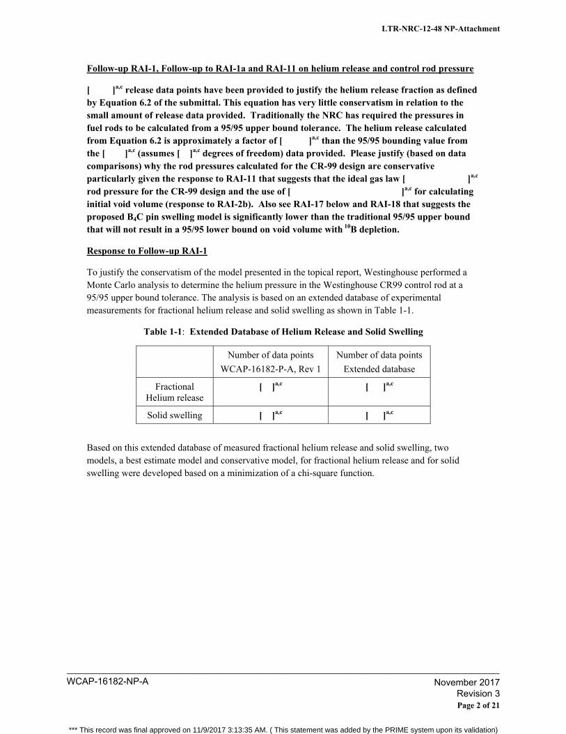
Follow-up RAI-1, Follow-up to RAI-1a and RAI-11 on helium release and control rod pressure
[ ]a,c release data points have been provided to justify the helium release fraction as defined by Equation 6.2 of the submittal. This equation has very little conservatism in relation to the small amount of release data provided. Traditionally the NRC has required the pressures in fuel rods to be calculated from a 95/95 upper bound tolerance. The helium release calculated from Equation 6.2 is approximately a factor of [ ]a,c than the 95/95 bounding value from the [ ]a,c (assumes [ ]a,c degrees of freedom) data provided. Please justify (based on data comparisons) why the rod pressures calculated for the CR-99 design are conservative particularly given the response to RAI-11 that suggests that the ideal gas law [ ]a,c rod pressure for the CR-99 design and the use of [ ]a,c for calculating initial void volume (response to RAI-2b). Also see RAI-17 below and RAI-18 that suggests the proposed B4C pin swelling model is significantly lower than the traditional 95/95 upper bound that will not result in a 95/95 lower bound on void volume with 10B depletion.
Response to Follow-up RAI-1
To justify the conservatism of the model presented in the topical report, Westinghouse performed a Monte Carlo analysis to determine the helium pressure in the Westinghouse CR99 control rod at a 95/95 upper bound tolerance. The analysis is based on an extended database of experimental measurements for fractional helium release and solid swelling as shown in Table 1-1.
Table 1-1: Extended Database of Helium Release and Solid Swelling
Number of data points
WCAP-16182-P-A, Rev 1
Number of data points
Extended database
Fractional Helium release
[ ]a,c [ ]a,c
Solid swelling [ ]a,c [ ]a,c
Based on this extended database of measured fractional helium release and solid swelling, two models, a best estimate model and conservative model, for fractional helium release and for solid swelling were developed based on a minimization of a chi-square function.
LTR-NRC-12-48 NP-Attachment
Page 2 of 21
WCAP-16182-NP-A____________________________________________________________________________________
November 2017 Revision 3
*** This record was final approved on 11/9/2017 3:13:35 AM. ( This statement was added by the PRIME system upon its validation)
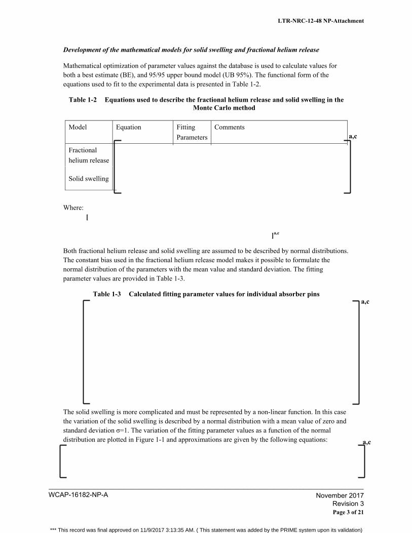
Development of the mathematical models for solid swelling and fractional helium release Mathematical optimization of parameter values against the database is used to calculate values for both a best estimate (BE), and 95/95 upper bound model (UB 95%). The functional form of the equations used to fit to the experimental data is presented in Table 1-2.
Table 1-2 Equations used to describe the fractional helium release and solid swelling in the Monte Carlo method
Model Equation Fitting
Parameters
Comments
Fractional
helium release
Solid swelling
Where: [
]a,c
Both fractional helium release and solid swelling are assumed to be described by normal distributions. The constant bias used in the fractional helium release model makes it possible to formulate the normal distribution of the parameters with the mean value and standard deviation. The fitting parameter values are provided in Table 1-3.
Table 1-3 Calculated fitting parameter values for individual absorber pins
The solid swelling is more complicated and must be represented by a non-linear function. In this case the variation of the solid swelling is described by a normal distribution with a mean value of zero and standard deviation σ=1. The variation of the fitting parameter values as a function of the normal distribution are plotted in Figure 1-1 and approximations are given by the following equations:
a,c
a,c
a,c
LTR-NRC-12-48 NP-Attachment
Page 3 of 21
WCAP-16182-NP-A____________________________________________________________________________________
November 2017 Revision 3
*** This record was final approved on 11/9/2017 3:13:35 AM. ( This statement was added by the PRIME system upon its validation)
The factor [ ]a,c is used to achieve the UB 95% confidence level ( [ ]a,c points in database).
Figure 1-1 Fitting Parameter variation as a function of upper bound level measured as a function of a variation with mean value zero and standard deviation σ=1. Data points from mathematical optimization and the approximation of the variation, solid line. No confidence level bands are provided in the plots.
A comparison between the individual models and the measurement database are presented in Figures 1-2 and 1-3. The sample standard deviation is calculated as:
6449.1
%95__
BEUBdeviationstndardSample
.
a,c
LTR-NRC-12-48 NP-Attachment
Page 4 of 21
WCAP-16182-NP-A____________________________________________________________________________________
November 2017 Revision 3
*** This record was final approved on 11/9/2017 3:13:35 AM. ( This statement was added by the PRIME system upon its validation)
Figure 1-2 Fractional helium release models and database.
Figure 1-3 Models of solid swelling and database.
a,c
a,c
LTR-NRC-12-48 NP-Attachment
Page 5 of 21
WCAP-16182-NP-A____________________________________________________________________________________
November 2017 Revision 3
*** This record was final approved on 11/9/2017 3:13:35 AM. ( This statement was added by the PRIME system upon its validation)
Method for calculation of the helium pressure
The method for calculating the helium pressure is based on the [
]a,c
V is the free volume,
P is the internal gaspressure,
R is the universal gas constant, 8.314 J/mole, K
T is the absolute gas temperature, K
n is the number of released moles of internal gas
The helium pressure calculations are performed for each hole of the Westinghouse CR99 control rod. The equations developed to describe the fractional helium release and solid swelling of the Hot Isostatic Pressed (HIP) B4C pins are described in the subsequent section.
Due to the non-linear relationship between fractional helium release, solid swelling and helium pressure in the [ ]a,c a Monte Carlo simulation was performed to find the upper bound 95% helium pressure. The Monte Carlo simulation calculated the helium pressure 5000 times using a random normal distribution of fractional helium release and solid swelling as described in Table 1-3 and the equations of parameters D1 and D2 for each absorber pin, (95% confidence level).
Definition of two examples
The method for calculating the helium pressure presented in WCAP-16182-P-A, Rev 1 is compared with the Monte Carlo method presented above through the use of two examples of the helium pressure calculation. Critical geometries of the CR 99 blades wings used in the calculations are given Tables 1-4 and 1-5. The control rod geometry in Example 1 and Example 2 describes typical D- and S-Lattice CR99. Example 1 includes 36 empty holes at the top resulting in larger free volume in the control rod and thus lower helium pressure. These two examples show the upper and lower limit of the helium pressure in a D- and S-lattice control rod.
LTR-NRC-12-48 NP-Attachment
Page 6 of 21
WCAP-16182-NP-A____________________________________________________________________________________
November 2017 Revision 3
*** This record was final approved on 11/9/2017 3:13:35 AM. ( This statement was added by the PRIME system upon its validation)
Table 1-4: Geometry definition Example 1
Table 1-5: Geometry definition Example 2
Comparison between the Monte Carlo method and WCAP-16182-P-A, Rev 1 method
The helium pressure is calculated for a control rod 10B average depletion of [ ]a,c. The depletion profile used in the example calculation is a profile known to generate the highest helium pressure for a given control rod average 10B depletion. The average temperature of the helium gas is [ ]a,c.
The results of the comparison between the Monte Carlo method and the WCAP method are shown in Table 1-6. Additionally, Figure 1-4 provides the distribution of results from the Monte Carlo calculations. The method presented in WCAP-16182-P-A, Rev 1 calculates higher helium pressures than the Monte Carlo method. The conclusion of the example calculations is that the method presented in WCAP-16182-P-A, Rev 1 is very conservative when compared to a Monte Carlo method at a 95/95 level.
Table 1-6 Comparison of calculated helium pressure
Method
WCAP-16182-P-A, Rev. 1
Monte Carlo
Method (95/95)
Difference
Example 1
Example 2
a,c
a,c
a,c
LTR-NRC-12-48 NP-Attachment
Page 7 of 21
WCAP-16182-NP-A____________________________________________________________________________________
November 2017 Revision 3
*** This record was final approved on 11/9/2017 3:13:35 AM. ( This statement was added by the PRIME system upon its validation)
Figure 1-4 Helium pressure variation from Monte Carlo simulation. At left Example 1 and at right Example 2.
a,c
LTR-NRC-12-48 NP-Attachment
Page 8 of 21
WCAP-16182-NP-A____________________________________________________________________________________
November 2017 Revision 3
*** This record was final approved on 11/9/2017 3:13:35 AM. ( This statement was added by the PRIME system upon its validation)
Follow-Up RAI-2
The recent paper by G. Ledberger, P. Seltborg and B. Rebensdorft “Mechanical Performance of the Westinghouse BWR CR 99 Control Rod at High Depletion Levels”, presented at the 2011 Water Reactor Fuel Performance Meeting in Changdu, China notes that cracking has been observed in the Generation 2 CR 99 design. The subject topical report states that the Generation 3 CR 99 was a redesign of Generation 2 to provide additional volume to prevent contact between the B4C pins and the blade wall. There are three concerns associated with the analyses presented in the current submittal for the Generation 3 CR 99 design:
1) The analysis of gap size appears to be based on the same upper bound B4C pin swelling model used for Generation 2 design that resulted in gap closure and cracking,
2) See Item 3 below that suggests the upper bound swelling model does not meet the traditional 95/95 upper bound traditionally used for licensing analyses, and
3) The depletion limit for Generation 3 appears to be in terms of average 10B depletion [ ]a,c while the paper notes that peak local 10B depletion can be considerably higher than the average resulting in peak swelling significantly higher than the average depletion level. This paper further notes that cracking first appeared in the locations of peak depletion. Please explain why a limit should not be established for a peak depletion level in the CR 99 Generation 3 control rod in addition to an average depletion. Did the peak depletion locations in Generation 2 [ ]a,c 10B depletion?
Also, from this paper it appears that free (non-constrained) swelling has been measured in the KKL pins but this swelling data has not been discussed in this submittal, please discuss this data in relation to the relevance to this submittal.
Response to Follow-up RAI-2
The solid swelling model is used for CR 99 Generation 2 and 3 when analyzing the pin to blade gap. In WCAP-16182-P-A, Rev 1 a [ ]a,c (Eq. 6.12 and 6.13). The data in Figure 1-3 shows that this is a very conservative assumption. This criterion is used to verify that a 100% density boron carbide pin cannot grow into contact with the blade.
However, as boron is self-shielding, the boron carbide pins have a diametrical depletion profile with the highest depletion at the surfaces and the lowest depletion at the center. This means that the solid pin swelling follows the same profile, i.e., the outer surface of the pins have higher solid swelling compared with the inner parts. This solid swelling profile results in compressive tangential stress at the surface and tensile stress in the inner part of the pins. When critical compressive stress at the surface is reached, a small part of the material near the surface will spall off, leading to porosity in the pin close to the surface. This process will continue inward to the pin center as the 10B depletion increases. Due to the porosity development during the 10B depletion, the outer layer of the pin will grow faster compared with the inner part of the pin. However, the porosity reduces the pin stiffness, so when the pin comes in contact with the blade wing, it is soft contact and the contact force that develops is small. The gap between the absorber pins and the blade wing hole wall is designed so that the soft contact and the resulting blade wing swelling do not lead to any deterioration of the mechanical performance of the control rods.
LTR-NRC-12-48 NP-Attachment
Page 9 of 21
WCAP-16182-NP-A____________________________________________________________________________________
November 2017 Revision 3
*** This record was final approved on 11/9/2017 3:13:35 AM. ( This statement was added by the PRIME system upon its validation)
The design strategy with CR 99 has been to accommodate the local depletion peaks by the optimized design of the absorber pins (e.g. adjusted pin diameter and tapered ends), which is possible with the high-density pins that can be manufactured with a desired geometrical shape (in contrast to standard boron carbide powder). The radial depletion peaks at the blade wing edges (Fig. 8, Ref. 2-1) are managed by the tapered ends. For the top zone, the possible axial depletion peak (Fig. 6, Ref. 2-1) is
managed by the reduced pin diameter in the top [
]a,c for Generation 2 CR 99). This means that the leading swelling will occur in the [ ]a,c (Fig. 10, Ref. 2-1) and, [ ]a,c, (Fig. 9, Ref. 2-1). At these locations, the depletion is very similar to the calculated node average depletion given by the nodal code simulator.
The operating conditions that the CR 99 control rods experienced in the KKL reactor were extraordinarily demanding (e.g. high power density, no low-enriched core bottom section), in particular for the control rod top, which caused the strong axial depletion peak shown in Fig. 6 (Ref.
2-1) (80% for the top hole as an average and 100% at the radial edge of it, Fig 8, Ref. 2-1). The effects of this on the blade swelling can also be seen in Fig. 9, which shows that the swelling of the top hole is actually higher than anywhere else. In US BWRs, under normal operating conditions, this very strong axial depletion peak will not occur and the 100% local depletion will not be reached within the licensed operating range (i.e. Nuclear End of Life (NEOL)). Hence, the local depletion peaks (radial and possibly minor axial peaks) are well accommodated by the CR 99 design and only the node average 10B depletion needs to be tracked.
The Top Fuel paper (Ref. 2-1) addresses and assesses the appearance and the probability of Irradiation Assisted Stress Corrosion Cracking (IASCC). However, the IASCC cracks that were detected on the KKL rods and analyzed were minor and very limited in extent and appearance. There were no open cracks and and no boron leakage from any of the rods, despite the very high depletion levels and the fact that the 7 cycle rod had been operating in regulating mode with IASCC cracks for more than one cycle. These inspection results show that, under normal operating conditions (i.e. without the extreme axial depletion peak achieved in KKL), CR 99 can operate well beyond NEOL without any impact on the nuclear or mechanical performance. Moreover, as explained in Ref. 2-1, the irradiation of the CR 99 rods to the high depletion levels reached in KKL was part of a well-planned and controlled evaluation program. The main objective of the program was to prove the robust behavior of CR 99, i.e. the full resistance to mechanical degradation and boron leakage at very high depletion levels and under operation with IASCC cracks. Hence, a limited number of minor IASCC cracks were expected to occur within the planned evaluation program and were successfully proven to have no impact on the safety function of the control rods.
References: 2-1 G. Ledergerber, P. Seltborg and B. Rebensdorff, “Mechanical Performance of the
Westinghouse BWR CR 99 Control Rod at High Depletion Levels,” 2011 Water Reactor Fuel Performance Meeting, Chengdu, China, September 11-14, 2011.
LTR-NRC-12-48 NP-Attachment
Page 10 of 21
WCAP-16182-NP-A____________________________________________________________________________________
November 2017 Revision 3
*** This record was final approved on 11/9/2017 3:13:35 AM. ( This statement was added by the PRIME system upon its validation)
Follow-up RAI-3, Follow up to RAI-1b:
[ ]a,c swelling data have been provided to justify the B4C swelling as defined by Equation 6.12 of the submittal. A 95/95 upper bound based on the [ ]a,c data points (assuming [ ]a,c degrees of freedom) is over a factor of [ ]a,c than the value applied in Equation 6.12. Therefore, the bounding Equation 6.12 provides a significantly lower bound than the traditional 95/95 bound of the data used in licensing analyses; please discuss why this is acceptable.
Response to Follow-up RAI-3: As discussed in the response to Follow-Up RAI-2, a [
]a,c (Eq. 6.12 and 6.13 in the topical). The data presented in Figure 1-3 show that this is a very conservative assumption. Additionally, this is shown to be conservative for significantly more data in the response to Follow-up RAI-1. Therefore, it is acceptable to use Equation 6.12 to calculate the B4C swelling.
LTR-NRC-12-48 NP-Attachment
Page 11 of 21
WCAP-16182-NP-A____________________________________________________________________________________
November 2017 Revision 3
*** This record was final approved on 11/9/2017 3:13:35 AM. ( This statement was added by the PRIME system upon its validation)
Follow-up RAI-4, Follow up to RAI-7:
In light of the small amount of helium release and swelling data provided and the cracking problems with the Generation 2 CR 99 design, the initial response appears inadequate. Please provide more comprehensive inspection and surveillance program or elaborate the reason otherwise.
Response to Follow-up RAI-4:
As discussed in the response to Follow-up RAI-2, one of the major advantages of Westinghouse control rods is that an IASCC crack in the blade wing is not a problem. An IASCC crack does not lead to loss of boron carbide and thus the nuclear performance is not impacted. This was clearly displayed in the high depletion program of CR 99 in KKL.
Westinghouse has a very extensive and rigorous inspection program for the BWR control rod blades (CRBs). This inspection program has been developed and refined during the last forty years of Westinghouse CRB manufacturing history. The BWR reactor core environment is very similar worldwide: similar thermal neutron flux, similar coolant temperatures, and similar core pressures. Therefore the robustness of the inspection program is dependent primarily on the particular core CRB operating strategies. The inspection programs are mainly performed in Europe because the CRB operating environment is more challenging than in the US. Most of the BWR reactors in Europe operate one year cycles, with the control blades continuously inserted during the cycle, i.e. no periodic control rod swaps like in the US. Some plants are operated with fuel bundles that are not equipped with natural uranium blankets in the bottom of the bundle. The high enrichment at the bottom of the bundle will result in higher neutron flux exposure on the top of the CRB even when the CRB is withdrawn from the core. The more challenging CRB operating mode in European reactors enables Westinghouse to achieve crucial data and experience much faster than an equivalent program in the US.
Thus, with the objective to achieve maximum information and conservatism in data acquired, Westinghouse is always aiming to study lead rods in the most demanding BWRs. The high depletion program of the 2nd generation CR 99 control rods was launched in the Swiss Leibstadt BWR/6 reactor (KKL) since it is the BWR that is operated with the highest core power density in the world, does not contain natural uranium blankets in the fuel, operates with long control rod insertion times and is thus a more challenging environment for control rods than the BWRs operating in the US. Furthermore, as also mentioned in the response to Follow-up RAI-2, the KKL program aimed at showing the IASCC threshold of the 2nd generation CR 99 control rod and the operation to this very high local depletion, was intentional. Thus the appearance of cracks in this aggressive KKL program is not regarded as a generic cracking problem for CRB in normal operation in the US.
The profilometry inspection program at KKL, documented in Reference 4-1, generated about [ ]a,c measurement data points that also have been compared with very detailed Monte Carlo (MCNP) calculations. Profilometry has earlier been performed on four highly irradiated CR 99 from the 1st generation. Today Westinghouse, consequently, has an extensive database on the irradiation induced behavior of HIP boron carbide pins. Through the profilometry programs, Westinghouse has quantified the material behavior as a function of neutron exposure. [
]a,c Thus the material behavior is known and Westinghouse will continue to follow leading rods, in BWRs
LTR-NRC-12-48 NP-Attachment
Page 12 of 21
WCAP-16182-NP-A____________________________________________________________________________________
November 2017 Revision 3
*** This record was final approved on 11/9/2017 3:13:35 AM. ( This statement was added by the PRIME system upon its validation)
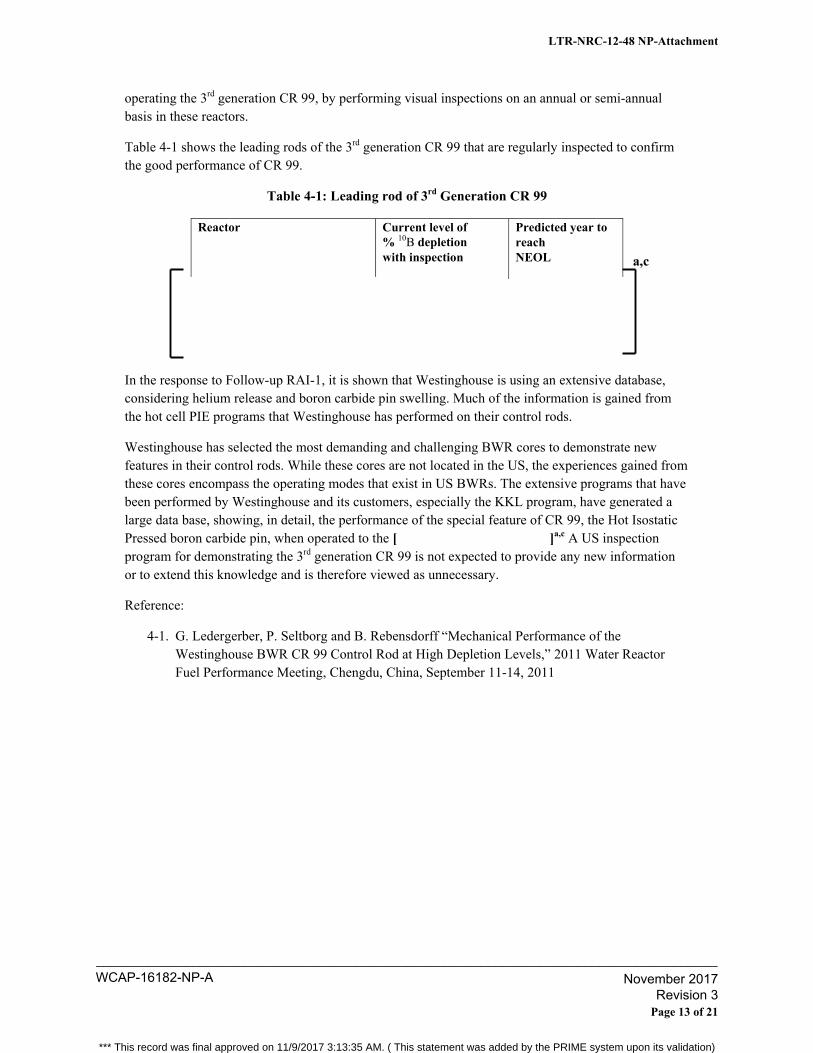
operating the 3rd generation CR 99, by performing visual inspections on an annual or semi-annual basis in these reactors.
Table 4-1 shows the leading rods of the 3rd generation CR 99 that are regularly inspected to confirm the good performance of CR 99.
Table 4-1: Leading rod of 3rd Generation CR 99
Reactor Current level of % 10B depletion with inspection
Predicted year to reach NEOL
In the response to Follow-up RAI-1, it is shown that Westinghouse is using an extensive database, considering helium release and boron carbide pin swelling. Much of the information is gained from the hot cell PIE programs that Westinghouse has performed on their control rods.
Westinghouse has selected the most demanding and challenging BWR cores to demonstrate new features in their control rods. While these cores are not located in the US, the experiences gained from these cores encompass the operating modes that exist in US BWRs. The extensive programs that have been performed by Westinghouse and its customers, especially the KKL program, have generated a large data base, showing, in detail, the performance of the special feature of CR 99, the Hot Isostatic Pressed boron carbide pin, when operated to the [ ]a,c A US inspection program for demonstrating the 3rd generation CR 99 is not expected to provide any new information or to extend this knowledge and is therefore viewed as unnecessary.
Reference:
4-1. G. Ledergerber, P. Seltborg and B. Rebensdorff “Mechanical Performance of the Westinghouse BWR CR 99 Control Rod at High Depletion Levels,” 2011 Water Reactor Fuel Performance Meeting, Chengdu, China, September 11-14, 2011
a,c
LTR-NRC-12-48 NP-Attachment
Page 13 of 21
WCAP-16182-NP-A____________________________________________________________________________________
November 2017 Revision 3
*** This record was final approved on 11/9/2017 3:13:35 AM. ( This statement was added by the PRIME system upon its validation)
Follow-up to RAI-5, Follow up to RAI-8:
Was the control blade evaluated for bending loads, such as a seismic channel bow load case? If evaluated please discuss, if not please provide justification why the bending loads were not considered.
Response to Follow-up RAI-5: No, Westinghouse does not evaluate bending loads.
Mechanical Criterion 5 (ME-5) states that the control rod should be capable of insertion into the core without structural damage in the presence of an oscillatory core. Westinghouse’s intention with this criterion is that the control rod worth should not be affected by an oscillatory core. When the control rod is inserted into the core the boron carbide should geometrically be located at designed positions so that the reactivity of the control rod is as designed and, consequently, safe shut down of the reactor is guaranteed.
The amplitude of the oscillation during Level D Safe Shutdown Earthquake (SSE) is [ ]a,c maximum calculated for Westinghouse SVEA-96 Optima 2 channels.
During a seismic event the core starts to vibrate and channels are designed to withstand the resulting forces. Due to the weight differences between the fuel and the control rod, the deformation in the core is transferred into the control rod when inserted into an oscillating core. Thus, the deformation of the control rod is restricted by the core deformation and is classified as a secondary stress.
[ ]a,c The average bending strain in an absorber blade at [
]a,c in the middle of the control rod was calculated and applied as a linear varying deformation over a representative section of the absorber part of the blade wing, half of a hole and ligament, see Figure 5-2.
Unirradiated material data based on the material specification was used in the calculation. The assumption of fresh material is conservative because neutron fluence will rapidly harden the material leading to less maximum straining of the material in the absorber wing. The elastic-plastic material behavior is modeled based on min specified values of Rp0.2 and Rm in Table 7-1 in Follow-up RAI-7, and [ ]a,c
[
]a,c
a,c
LTR-NRC-12-48 NP-Attachment
Page 14 of 21
WCAP-16182-NP-A____________________________________________________________________________________
November 2017 Revision 3
*** This record was final approved on 11/9/2017 3:13:35 AM. ( This statement was added by the PRIME system upon its validation)
Figure 5-1 Plastic data for fresh material used in the collapse analysis
In the evaluation it was stated that the control rod will meet all design and operating criteria after the combination of an Operational Basis Earthquake (OBE), Level B with amplitude defined as half of the SSE amplitude, followed by a SSE. According to NUREG-0800 Standard Review Plan 3.7.3 5 OBE events with [ ]a,c strain cycles each are assumed to occur during the lifetime of the nuclear power plant. One OBE can therefore be evaluated for [ ]a,c Ten [ ]a,c is also used in the load definition of the SSE. Fatigue data contained in Reference 5-1 was used in the evaluation.
Maximum local total equivalent strain was calculated to [ ]a,c in case of SSE, see Figure 5-3. The result in Figure 5-3 also shows that maximum local strain decreases to low values towards the control rod centre. Fatigue evaluation shows that usage factor [
]a,c The usage factor is less than 1 and therefore no fatigue damage will evolve due to earthquake conditions, ensuring that structural integrity and insertability is maintained.
a,c
LTR-NRC-12-48 NP-Attachment
Page 15 of 21
WCAP-16182-NP-A____________________________________________________________________________________
November 2017 Revision 3
*** This record was final approved on 11/9/2017 3:13:35 AM. ( This statement was added by the PRIME system upon its validation)
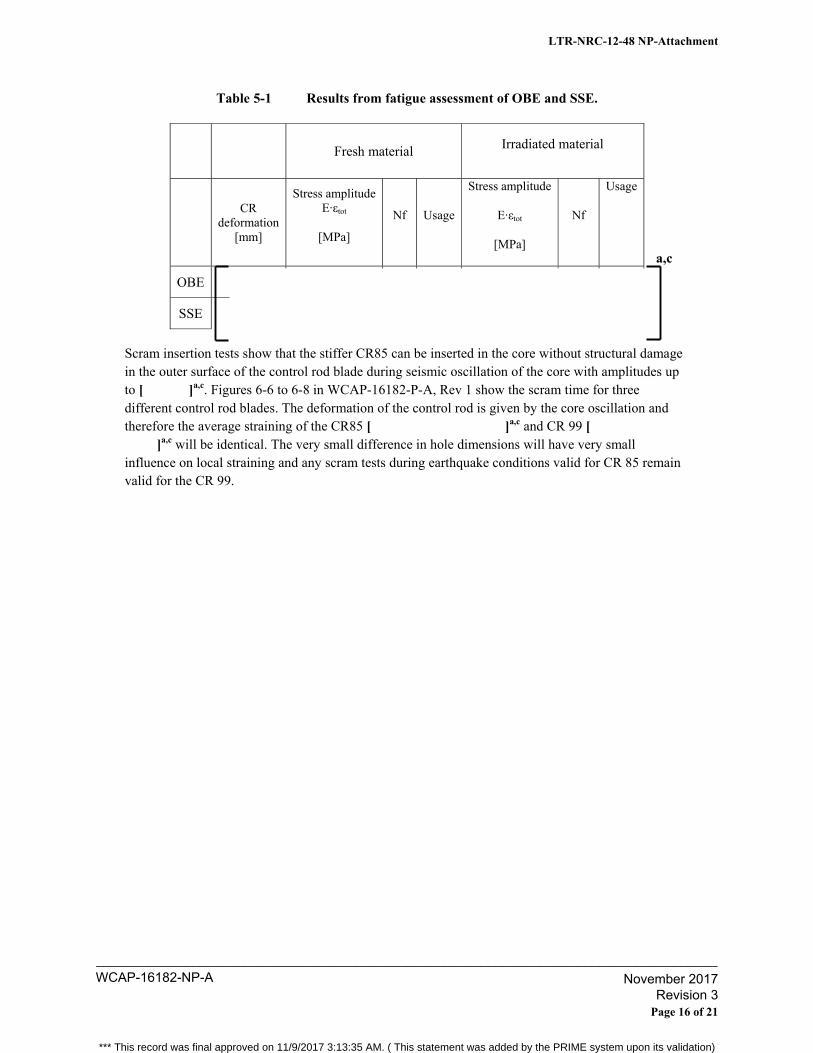
Table 5-1 Results from fatigue assessment of OBE and SSE.
Fresh material Irradiated material
CR deformation
[mm]
Stress amplitude E·εtot
[MPa]
Nf Usage
Stress amplitude
E·εtot
[MPa]
Nf
Usage
OBE
SSE
Scram insertion tests show that the stiffer CR85 can be inserted in the core without structural damage in the outer surface of the control rod blade during seismic oscillation of the core with amplitudes up to [ ]a,c. Figures 6-6 to 6-8 in WCAP-16182-P-A, Rev 1 show the scram time for three different control rod blades. The deformation of the control rod is given by the core oscillation and therefore the average straining of the CR85 [ ]a,c and CR 99 [
]a,c will be identical. The very small difference in hole dimensions will have very small influence on local straining and any scram tests during earthquake conditions valid for CR 85 remain valid for the CR 99.
a,c
LTR-NRC-12-48 NP-Attachment
Page 16 of 21
WCAP-16182-NP-A____________________________________________________________________________________
November 2017 Revision 3
*** This record was final approved on 11/9/2017 3:13:35 AM. ( This statement was added by the PRIME system upon its validation)
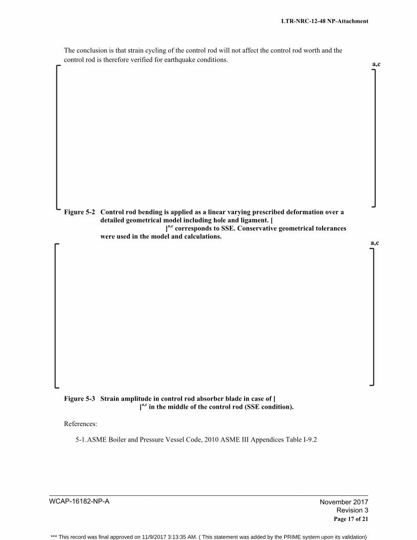
The conclusion is that strain cycling of the control rod will not affect the control rod worth and the control rod is therefore verified for earthquake conditions.
Figure 5-2 Control rod bending is applied as a linear varying prescribed deformation over a detailed geometrical model including hole and ligament. [
]a,c corresponds to SSE. Conservative geometrical tolerances were used in the model and calculations.
Figure 5-3 Strain amplitude in control rod absorber blade in case of [ ]a,c in the middle of the control rod (SSE condition).
References:
5-1. ASME Boiler and Pressure Vessel Code, 2010 ASME III Appendices Table I-9.2
a,c
a,c
LTR-NRC-12-48 NP-Attachment
Page 17 of 21
WCAP-16182-NP-A____________________________________________________________________________________
November 2017 Revision 3
*** This record was final approved on 11/9/2017 3:13:35 AM. ( This statement was added by the PRIME system upon its validation)
Follow-up RAI-6, Follow up to RAI-12:
(1) Mechanical Criterion 5 requires the control rod be insertable into the core without structural damage during a certain specified oscillatory fuel channel deflection. Does this analysis take into account possible creep strains in the control rods that could affect insertion?
(2) The proof of insertion appears to be that the CR-99 rod is more compatible than the CR-85 rod, and the CR-85 rod was found to be acceptably insertable during testing. However, the CR-99 appears to be operating at a higher stress state and insertion stresses could increase with rod compatibility, leading to a more potentially damaging mechanism for the CR-99. How does the requirement of no structural damage address this concern?
Response to Follow-up RAI-6: (1) No, this analysis does not take into account possible creep strains in the control rods. As was
discussed in the original response to RAI-12, the increased stress level in CR99 is due mainly to the higher Helium pressure limit. However, the influence of Helium pressure on creep strains is low and is therefore negligible.
(2) Westinghouse considers the requirement of no structural damage to be met as long as the
control rod can be inserted into the core without loss of boron carbide. The mechanical integrity is viewed to be acceptable provided that there is no loss of rod worth as a result of IASCC. Additional verification of the mechanical integrity for the CR 99 Generation 3 at higher stress states is discussed in the response to RAI-5 of this document.
LTR-NRC-12-48 NP-Attachment
Page 18 of 21
WCAP-16182-NP-A____________________________________________________________________________________
November 2017 Revision 3
*** This record was final approved on 11/9/2017 3:13:35 AM. ( This statement was added by the PRIME system upon its validation)
Follow-up RAI-7, Follow up to RAI-15
What is the allowable design limit (Sm) value for stainless steel used in the CR-99 evaluation? What is the difference in Sm values using [ ]a,c stress criteria? Also justify the reduced stress conversion factor for the fatigue calculation (Equation 6.7) from that provided in Reference 2.
Response to Follow-up RAI-7:
Allowable design limits are based on internal Westinghouse material specifications, which are used when ordering material for use in manufacturing control rods. All of the material lots delivered to Westinghouse are tested in order to verify that the material specification is fulfilled. Min material data are given in Table 7-1.
The [ ]a,c design limits are not identical. The allowable [ ]a,c design limit (finite element calculations) is calculated according to:
This method can be compared with the ASME definition of Sm (analytical calculations):
and with the KTA 3103 (standard for shut down systems) definition:
where RT is room temperature and T is actual temperature. Comparison of [ ]a,c derivation of Sm shows that the [ ]a,c equation is conservative compared with KTA 3103.
a,c
a,c
a,c
LTR-NRC-12-48 NP-Attachment
Page 19 of 21
WCAP-16182-NP-A____________________________________________________________________________________
November 2017 Revision 3
*** This record was final approved on 11/9/2017 3:13:35 AM. ( This statement was added by the PRIME system upon its validation)
Table 7-1 Material data for fresh stainless steel AISI 316L. Bold numbers are taken directly from material specification, other scaled based on these numbers and knowledge of typical dependence of temperature for austenitic stainless steels.
Equation 6.7 in the topical report is used to calculate current stress state for any condition during lifetime. Fatigue assessment is based on stress range as defined in Equation 6.8 of the topical. This stress range is calculated as maximum possible between end of life conditions and beginning of life conditions.
a,c
LTR-NRC-12-48 NP-Attachment
Page 20 of 21
WCAP-16182-NP-A____________________________________________________________________________________
November 2017 Revision 3
*** This record was final approved on 11/9/2017 3:13:35 AM. ( This statement was added by the PRIME system upon its validation)
Follow-up RAI-8, Follow up to RAI-8
Do stresses in the structural finite element models exceed the elastic range? If so, is plastic material behavior modeled? If plastic is modeled please provide a description of the model.
Response to Follow-up RAI-8:
All structural analyses are done based on linear elastic assumption. [ ]a,c Local stress concentration is controlled so that no ratcheting
takes place due to load cycling, Pm+Pb+Q<3*Sm. Controlling the local stress concentration ensures that an initial plastic response leads to a pure elastic cycling.
LTR-NRC-12-48 NP-Attachment
Page 21 of 21
WCAP-16182-NP-A____________________________________________________________________________________
November 2017 Revision 3
*** This record was final approved on 11/9/2017 3:13:35 AM. ( This statement was added by the PRIME system upon its validation)
Westinghouse Non-Proprietary Class 3
WCAP-16182-NP-A November 2017 Revision 3
Section D
Audits
*** This record was final approved on 11/9/2017 3:13:35 AM. ( This statement was added by the PRIME system upon its validation)
8 Westinghouse
U.S. Nuclear Regulatory Commission Document Control Desk 11555 Rockville Pike Rockville, MD 20852
Westinghouse Electric Company Nuclear Services 1000 Westinghouse Drive Cranberry Township, Pennsylvania 16066 USA
Direct tel: (412) 374-4643 Direct fax: (724) 720-0754
e-mail: [email protected]
L TR-NRC-12-67
September 19,2012
Subject: Resolution of Open Items from NRC Audit on WCAP-16182-P-A, Revision 1, "Westinghouse BWR Control Rod CR 99 Licensing Report- Update to Mechanical Design Limits" (Proprietary/Non-Proprietary)
Enclosed are the proprietary and non-proprietary versions of, "Resolution of Open Audit Items from NRC Audit on WCAP-16182-P-A, Revision 1, 'Westinghouse BWR Control Rod CR 99 Licensing ReportUpdate to Mechanical Design Limits."' This audit was held at the Rockville, MD office on August 22, 2012.
Also enclosed is:
1. One (1) copy of the Application for Withholding Proprietary Information from Public Disclosure, AW-12-3543 (Non-Proprietary), with Proprietary Information Notice and Copyright Notice.
2. One (1) copy of Affidavit (Non-Proprietary).
This submittal contains proprietary information of Westinghouse Electric Company LLC. In conformance with the requirements of 10 CFR Section 2.390, as amended, of the Commission's regulations, we are enclosing with this submittal an Application for Withholding Proprietary Information from Public Disclosure and an affidavit. The affidavit sets forth the basis on which the information identified as proprietary may be withheld from public disclosure by the Commission.
Correspondence with respect to the proprietary aspects of the application for withholding or the Westinghouse affidavit should reference A W-12-3543, and should be addressed to J. A. Gresham, Manager, Regulatory Compliance, Westinghouse Electric Company, Suite 428, 1000 Westinghouse Drive, Cranberry Township, Pennsylvania 16066.
J:ry. tq.tcr-y yo· rs, rb OJ ~ A. Gresham, Manager
Regulatory Compliance
Enclosures
WCAP-16182-NP-A____________________________________________________________________________________
November 2017 Revision 3
*** This record was final approved on 11/9/2017 3:13:35 AM. ( This statement was added by the PRIME system upon its validation)
WCAP-16182-NP-A____________________________________________________________________________________
November 2017 Revision 3
*** This record was final approved on 11/9/2017 3:13:35 AM. ( This statement was added by the PRIME system upon its validation)
WCAP-16182-NP-A____________________________________________________________________________________
November 2017 Revision 3
*** This record was final approved on 11/9/2017 3:13:35 AM. ( This statement was added by the PRIME system upon its validation)

AW-12-3543
2
(1) I am Manager, Regulatory Compliance, in Nuclear Services, Westinghouse Electric
Company LLC (Westinghouse), and as such, I have been specifically delegated the function of
reviewing the proprietary information sought to be withheld from public disclosure in connection
with nuclear power plant licensing and rule making proceedings, and am authorized to apply for
its withholding on behalf of Westinghouse.
(2) I am making this Affidavit in conformance with the provisions of 10 CFR Section 2.390 of the
Commission's regulations and in conjunction with the Westinghouse Application for Withholding
Proprietary Information from Public Disclosure accompanying this Affidavit.
(3) I have personal knowledge of the criteria and procedures utilized by Westinghouse in designating
information as a trade secret, privileged or as confidential commercial or financial information.
(4) Pursuant to the provisions of paragraph (b)(4) of Section 2.390 of the Commission's regulations,
the following is furnished for consideration by the Commission in determining whether the
information sought to be withheld from public disclosure should be withheld.
(i) The information sought to be withheld from public disclosure is owned and has been held
in confidence by Westinghouse.
(ii) The information is of a type customarily held in confidence by Westinghouse and not
customarily disclosed to the public. Westinghouse has a rational basis for determining
the types of information customarily held in confidence by it and, in that connection,
utilizes a system to determine when and whether to hold certain types of information in
confidence. The application of that system and the substance of that system constitutes
Westinghouse policy and provides the rational basis required.
Under that system, information is held in confidence if it falls in one or more of several
types, the release of which might result in the loss of an existing or potential competitive
advantage, as follows:
(a) The information reveals the distinguishing aspects of a process (or component,
structure, tool, method, etc.) where prevention of its use by any of
WCAP-16182-NP-A____________________________________________________________________________________
November 2017 Revision 3
*** This record was final approved on 11/9/2017 3:13:35 AM. ( This statement was added by the PRIME system upon its validation)

AW-12-3543
3
Westinghouse’s competitors without license from Westinghouse constitutes a
competitive economic advantage over other companies.
(b) It consists of supporting data, including test data, relative to a process (or
component, structure, tool, method, etc.), the application of which data secures a
competitive economic advantage, e.g., by optimization or improved
marketability.
(c) Its use by a competitor would reduce his expenditure of resources or improve his
competitive position in the design, manufacture, shipment, installation, assurance
of quality, or licensing a similar product.
(d) It reveals cost or price information, production capacities, budget levels, or
commercial strategies of Westinghouse, its customers or suppliers.
(e) It reveals aspects of past, present, or future Westinghouse or customer funded
development plans and programs of potential commercial value to Westinghouse.
(f) It contains patentable ideas, for which patent protection may be desirable.
There are sound policy reasons behind the Westinghouse system which include the
following:
(a) The use of such information by Westinghouse gives Westinghouse a competitive
advantage over its competitors. It is, therefore, withheld from disclosure to
protect the Westinghouse competitive position.
(b) It is information that is marketable in many ways. The extent to which such
information is available to competitors diminishes the Westinghouse ability to
sell products and services involving the use of the information.
(c) Use by our competitor would put Westinghouse at a competitive disadvantage by
reducing his expenditure of resources at our expense.
WCAP-16182-NP-A____________________________________________________________________________________
November 2017 Revision 3
*** This record was final approved on 11/9/2017 3:13:35 AM. ( This statement was added by the PRIME system upon its validation)
AW-12-3543
4
(d) Each component of proprietary information pertinent to a particular competitive
advantage is potentially as valuable as the total competitive advantage. If
competitors acquire components of proprietary information, any one component
may be the key to the entire puzzle, thereby depriving Westinghouse of a
competitive advantage.
(e) Unrestricted disclosure would jeopardize the position of prominence of
Westinghouse in the world market, and thereby give a market advantage to the
competition of those countries.
(f) The Westinghouse capacity to invest corporate assets in research and
development depends upon the success in obtaining and maintaining a
competitive advantage.
(iii) The information is being transmitted to the Commission in confidence and, under the
provisions of 10 CFR Section 2.390, it is to be received in confidence by the
Commission.
(iv) The information sought to be protected is not available in public sources or available
information has not been previously employed in the same original manner or method to
the best of our knowledge and belief.
(v) The proprietary information sought to be withheld in this submittal is that which is
appropriately marked in LTR-NRC-12-67 P-Attachment, “Resolution of Open Items from
NRC Audit on WCAP-16182-P-A, Revision 1, ‘Westinghouse BWR Control Rod CR 99
Licensing Report – Update to Mechanical Design Limits’” (Proprietary), for submittal to
the Commission, being transmitted by Westinghouse letter, LTR-NRC-12-67, and
Application for Withholding Proprietary Information from Public Disclosure, to the
Document Control Desk. The proprietary information as submitted by Westinghouse is
that associated with Westinghouse’s request for NRC approval of WCAP-16182-P-A,
Revision 1, and may be used only for that purpose.
WCAP-16182-NP-A____________________________________________________________________________________
November 2017 Revision 3
*** This record was final approved on 11/9/2017 3:13:35 AM. ( This statement was added by the PRIME system upon its validation)
AW-12-3543
5
This information is part of that which will enable Westinghouse to:
(a) Obtain NRC approval of WCAP-16182-P-A, Revision 1, “Westinghouse BWR
Control Rod CR 99 Licensing Report – Update to Mechanical Design Limits.”
(b) Extend the mechanical lifetime of Westinghouse BWR control blades.
Further this information has substantial commercial value as follows:
(a) Westinghouse plans to sell the use of this information to its customers for the
purpose of assisting customers in obtaining license changes.
(b) The information requested to be withheld reveals the distinguishing aspects of a
methodology which was developed by Westinghouse.
Public disclosure of this proprietary information is likely to cause substantial harm to the
competitive position of Westinghouse because it would enhance the ability of
competitors to provide similar fuel designs and licensing defense services for commercial
power reactors without commensurate expenses. Also, public disclosure of the
information would enable others to use the information to meet NRC requirements for
licensing documentation without purchasing the right to use the information.
The development of the technology described in part by the information is the result of
applying the results of many years of experience in an intensive Westinghouse effort and
the expenditure of a considerable sum of money.
In order for competitors of Westinghouse to duplicate this information, similar technical
programs would have to be performed and a significant manpower effort, having the
requisite talent and experience, would have to be expended.
Further the deponent sayeth not.
WCAP-16182-NP-A____________________________________________________________________________________
November 2017 Revision 3
*** This record was final approved on 11/9/2017 3:13:35 AM. ( This statement was added by the PRIME system upon its validation)

Proprietary Information Notice
Transmitted herewith are proprietary and/or non-proprietary versions of documents furnished to the NRC in connection with requests for generic and/or plant-specific review and approval. In order to conform to the requirements of 10 CFR 2.390 of the Commission's regulations concerning the protection of proprietary information so submitted to the NRC, the information which is proprietary in the proprietary versions is contained within brackets, and where the proprietary information has been deleted in the non-proprietary versions, only the brackets remain (the information that was contained within the brackets in the proprietary versions having been deleted). The justification for claiming the information so designated as proprietary is indicated in both versions by means of lower case letters (a) through (f) located as a superscript immediately following the brackets enclosing each item of information being identified as proprietary or in the margin opposite such information. These lower case letters refer to the types of information Westinghouse customarily holds in confidence identified in Sections (4)(ii)(a) through (4)(ii)(f) of the affidavit accompanying this transmittal pursuant to 10 CFR 2.390(b)(1).
Copyright Notice The reports transmitted herewith each bear a Westinghouse copyright notice. The NRC is permitted to make the number of copies of the information contained in these reports which are necessary for its internal use in connection with generic and plant-specific reviews and approvals as well as the issuance, denial, amendment, transfer, renewal, modification, suspension, revocation, or violation of a license, permit, order, or regulation subject to the requirements of 10 CFR 2.390 regarding restrictions on public disclosure to the extent such information has been identified as proprietary by Westinghouse, copyright protection notwithstanding. With respect to the non-proprietary versions of these reports, the NRC is permitted to make the number of copies beyond those necessary for its internal use which are necessary in order to have one copy available for public viewing in the appropriate docket files in the public document room in Washington, DC and in local public document rooms as may be required by NRC regulations if the number of copies submitted is insufficient for this purpose. Copies made by the NRC must include the copyright notice in all instances and the proprietary notice if the original was identified as proprietary.
WCAP-16182-NP-A____________________________________________________________________________________
November 2017 Revision 3
*** This record was final approved on 11/9/2017 3:13:35 AM. ( This statement was added by the PRIME system upon its validation)
Westinghouse Non-Proprietary Class 3
LTR-NRC-12-67 NP-Attachment TAC No. ME2630
Resolution of Open Items from NRC Audit on WCAP-16182-P-A, Revision 1, “Westinghouse BWR Control Rod CR 99 Licensing Report – Update to Mechanical Design Limits”
(Non-Proprietary)
September 2012
Westinghouse Electric Company 1000 Westinghouse Drive
Cranberry Township, PA 16066
© 2012 Westinghouse Electric Company LLC All Rights Reserved
WCAP-16182-NP-A____________________________________________________________________________________
November 2017 Revision 3
*** This record was final approved on 11/9/2017 3:13:35 AM. ( This statement was added by the PRIME system upon its validation)
Open Item #1 Provide a full table of results based on [ ]a,c with the respective Design Ratios. Include the [ ]a,c intensity and the Design Ratios for all load cases in the topical report using the models of record. [
]a,c and representative plots of the [ ]a,c for the limiting load case. Provide this data for all three lattices.
Answer 1
The models of record used in WCAP-16182-P-A, Rev. 1 are documented in the following two
internal Westinghouse calculation reports:
1. BTM 09-0624, rev 0, “BWR Control Rod CR 99 for BWR/2-4 and BWR/6 Reactors with D- and
S-lattice. Mechanical end of Life prediction and Stress analysis,” 2009
2. BTA 07-0400, rev 0, “Stress Analysis of Control Rod CR 99 for BWR Reactors with C-
lattice,”2007.
Description of finite element models (FEM) Data contained in Table 1 was used as input to the FE-models. Figure 1 shows a representation of
the boundary conditions used in the models. Figure 2 shows where pressure loads were applied
during the analysis. The scram force application is shown in Figure 3.
Table 1 Material data and allowable stress according to WCAP-16182-P-A, Rev 1 and ASME-NB.
Temp, oC 20 85 300 310 350
a,c
LTR-NRC-12-67 NP-Attachment
Page 1 of 28
WCAP-16182-NP-A____________________________________________________________________________________
November 2017 Revision 3
*** This record was final approved on 11/9/2017 3:13:35 AM. ( This statement was added by the PRIME system upon its validation)
Figure 1 ώ ]a,c 1
Figure 2 ώ
]a,c
1 An ANSYS Work Bench model has been used to simplify the visualization of boundary conditions and applied
loads.
a,c
a,c
LTR-NRC-12-67 NP-Attachment
Page 2 of 28
WCAP-16182-NP-A____________________________________________________________________________________
November 2017 Revision 3
*** This record was final approved on 11/9/2017 3:13:35 AM. ( This statement was added by the PRIME system upon its validation)
Figure 3 ώ ]a,c
Two load cases were analyzed using finite element analysis for the stress evaluation consistent with
what is presented in WCAP-16182-P-A, Rev. 1. The first case analyzes a pressure load applied at
operating conditions and end of life (EOL), and the second case analyzes a cold scram load at EOL. Both
analyses were carried out for S, D and C lattice plants. The results of each analysis are presented as
follows:
a,c
LTR-NRC-12-67 NP-Attachment
Page 3 of 28
WCAP-16182-NP-A____________________________________________________________________________________
November 2017 Revision 3
*** This record was final approved on 11/9/2017 3:13:35 AM. ( This statement was added by the PRIME system upon its validation)
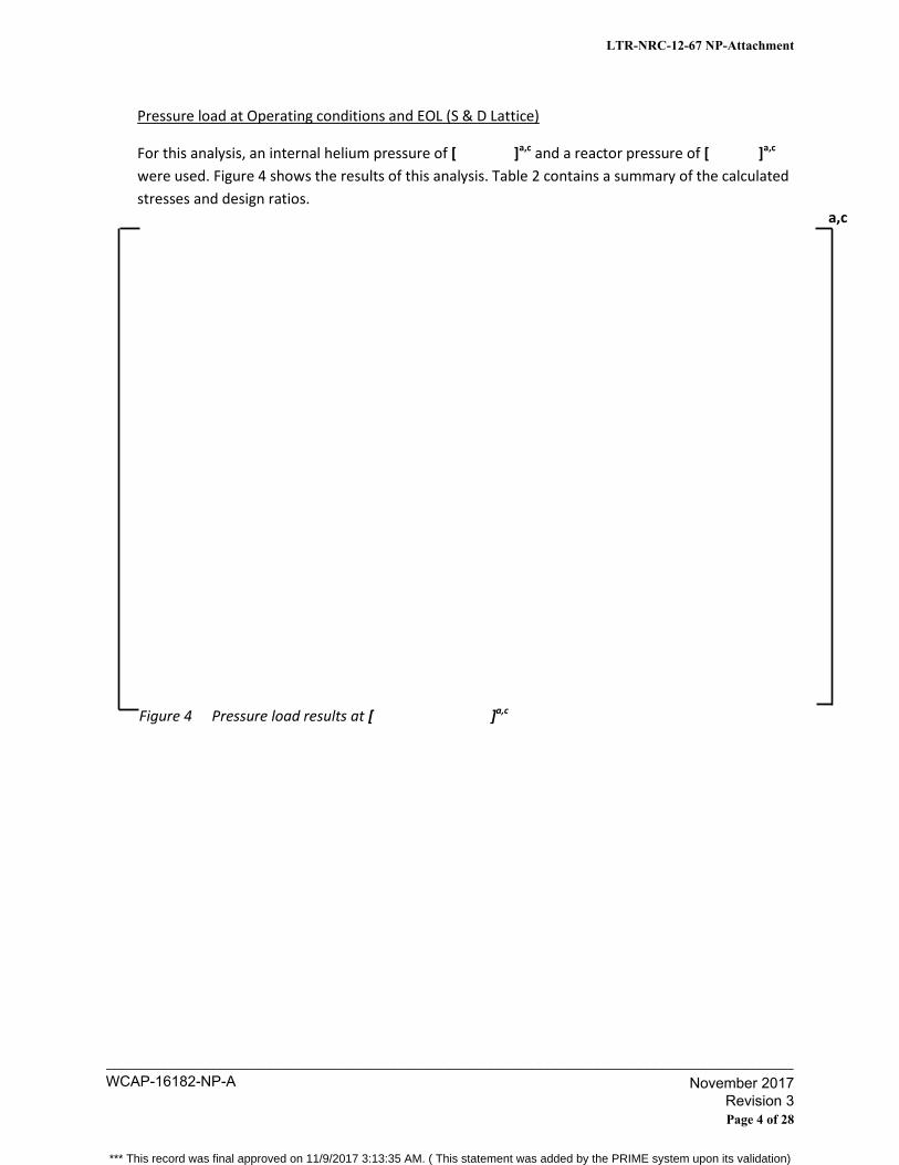
Pressure load at Operating conditions and EOL (S & D Lattice)
For this analysis, an internal helium pressure of [ ]a,c and a reactor pressure of [ ]a,c
were used. Figure 4 shows the results of this analysis. Table 2 contains a summary of the calculated
stresses and design ratios.
Figure 4 Pressure load results at [ ]a,c
a,c
LTR-NRC-12-67 NP-Attachment
Page 4 of 28
WCAP-16182-NP-A____________________________________________________________________________________
November 2017 Revision 3
*** This record was final approved on 11/9/2017 3:13:35 AM. ( This statement was added by the PRIME system upon its validation)
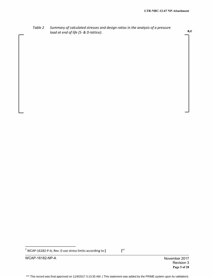
Table 2 Summary of calculated stresses and design ratios in the analysis of a pressure load at end of life (S- & D-lattice).
2 WCAP-16182-P-A, Rev. 0 use stress limits according to [ ]
a,c
a,c
LTR-NRC-12-67 NP-Attachment
Page 5 of 28
WCAP-16182-NP-A____________________________________________________________________________________
November 2017 Revision 3
*** This record was final approved on 11/9/2017 3:13:35 AM. ( This statement was added by the PRIME system upon its validation)

Cold scram load at EOL (S & D Lattice)
For this analysis, an internal helium pressure of [ ]a,c and a reactor pressure of [ ]a,c
were used, consistent with a temperature of [ ]a,c Figure 5 shows the results. Table 3 contains
a summary of the calculated stresses and design ratios for the analysis.
Figure 5 Cold tensile scram results for MEOL [ ]a,c
a,c
LTR-NRC-12-67 NP-Attachment
Page 6 of 28
WCAP-16182-NP-A____________________________________________________________________________________
November 2017 Revision 3
*** This record was final approved on 11/9/2017 3:13:35 AM. ( This statement was added by the PRIME system upon its validation)
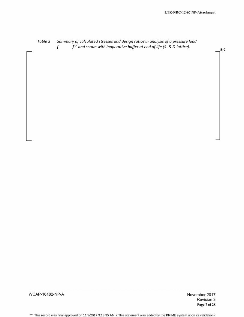
Table 3 Summary of calculated stresses and design ratios in analysis of a pressure load [ ]a,c and scram with inoperative buffer at end of life (S- & D-lattice).
a,c
LTR-NRC-12-67 NP-Attachment
Page 7 of 28
WCAP-16182-NP-A____________________________________________________________________________________
November 2017 Revision 3
*** This record was final approved on 11/9/2017 3:13:35 AM. ( This statement was added by the PRIME system upon its validation)

Pressure load at Operating conditions and EOL (C Lattice)
For this analysis, an internal helium pressure of [ ]a,c and a reactor pressure of [ ]a,c
were used. Figure 6 shows the results. Table 4 contains a summary of the calculated stresses and
design ratios for the analysis.
Figure 6 Pressure load at MEOL [ ]a,c
a,c
LTR-NRC-12-67 NP-Attachment
Page 8 of 28
WCAP-16182-NP-A____________________________________________________________________________________
November 2017 Revision 3
*** This record was final approved on 11/9/2017 3:13:35 AM. ( This statement was added by the PRIME system upon its validation)
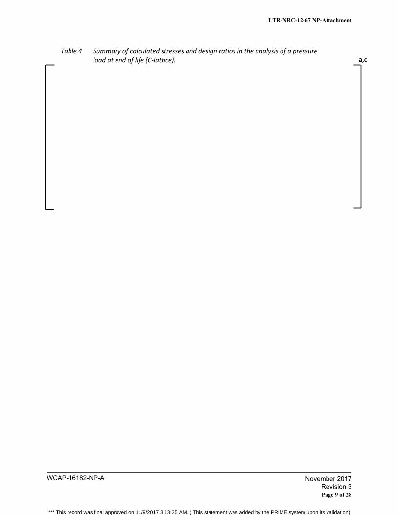
Table 4 Summary of calculated stresses and design ratios in the analysis of a pressure load at end of life (C-lattice).
a,c
LTR-NRC-12-67 NP-Attachment
Page 9 of 28
WCAP-16182-NP-A____________________________________________________________________________________
November 2017 Revision 3
*** This record was final approved on 11/9/2017 3:13:35 AM. ( This statement was added by the PRIME system upon its validation)

Cold scram load at EOL (C Lattice)
For this analysis, an internal helium pressure of [ ]a,c and a reactor pressure of [ ]a,c
were used, consistent with a temperature of [ ]a,c Figure 7 shows the results. Table 5 contains
a summary of the calculated stresses and design ratios for the analysis.
Figure 7 Cold scram load at MEOL [ ]a,c
a,c
LTR-NRC-12-67 NP-Attachment
Page 10 of 28
WCAP-16182-NP-A____________________________________________________________________________________
November 2017 Revision 3
*** This record was final approved on 11/9/2017 3:13:35 AM. ( This statement was added by the PRIME system upon its validation)
Table 5 Summary of calculated stresses and design ratios in analysis of a pressure load [ ]a,c and scram with inoperative buffer at end of life (C-lattice).
a,c
LTR-NRC-12-67 NP-Attachment
Page 11 of 28
WCAP-16182-NP-A____________________________________________________________________________________
November 2017 Revision 3
*** This record was final approved on 11/9/2017 3:13:35 AM. ( This statement was added by the PRIME system upon its validation)
Open Item #2 Provide supporting documentation of the convection surface coefficient and thermal link elements. Provide a summary of the thermal model and thermal link elements as documented in BR 92‐345 and BTA 03‐139. Answer #2
Summary of BR 92‐345 The report presents a study performed to determine the heat transfer coefficients at control rod surfaces in the Swedish BWRs [ ]a,c with the following range of assumptions:
[ ]a,c
[ ]a,c
[ ]a,c
[ ]a,c
[ ]a,c It was determined that the heat transfer coefficient was between [
]a,c
Summary BTA 03‐139 Convection Surface Coefficient Based on the heat transfer data calculated in BR 92‐345, a conservative equation for calculating the convection surface coefficient at the control rod blade wing surface can be expressed as:
]a,c Eq. 1 where q is the surface heat flow in W/(m2 °K). The first term reflects the forced convection (macro convection) and the other term reflects the possible occurrence [
]a,c The heat transfer coefficient is below or in the lower range of what was determined in the study in BR 92‐345 and is therefore conservative. Thermal link element Thermal convection between pin and blade is modeled in the thermal finite element model by link elements. [
]a,c Therefore, the thermal conductance, hint (W/m2 K), across the B4C/stainless‐steel interface can be described as:
LTR-NRC-12-67 NP-Attachment
Page 12 of 28
WCAP-16182-NP-A____________________________________________________________________________________
November 2017 Revision 3
*** This record was final approved on 11/9/2017 3:13:35 AM. ( This statement was added by the PRIME system upon its validation)
[ ]a,c Eq. 2
where [
]a,c The helium gas conductivity, kg (W/m K), may be written as:
bg aTk Eq. 3
The properties of the surfaces and the gap width play a role in the interfacial heat transfer as
well. Since the gap width is assumed to be [ ]a,c the gas conductivity function must be completed to reveal the [
]a,c. It can be written according to:
Eq. 4
where
λ0 = Property of helium (Pa, m) P = gas pressure (Pa) Rm = the mean contact surfaces roughness (m)
G0() = peak to peak gap size where = the circumferential angle around the gap.
[ ]a,c Eq. 5
R1 and R2 are the estimated [ ]a,c for the HIP B4C pin and stainless
steel, respectively, in meters. [ ]a,c
At the contact points (G0 0), where the pin rests in the hole, [ ]a,c
Eq. 6
whereCBk
4 and kss are the thermal conductivity for B4C and stainless steel, respectively. [
]a,c and H is the Mayer hardness of the softer material (stainless steel). It should be noted that the interfacial heat transfer in [
]a,c
The equation describing the convection link element in ANSYS is:
kji TTAhq int Eq. 7
a,c
a,c
LTR-NRC-12-67 NP-Attachment
Page 13 of 28
WCAP-16182-NP-A____________________________________________________________________________________
November 2017 Revision 3
*** This record was final approved on 11/9/2017 3:13:35 AM. ( This statement was added by the PRIME system upon its validation)
where
q = heat flow rate (W).
hf = film coefficient (W/m2 K). Ai = area* for convection link element (m2).
Tj, Tk = link temperatures (K) at end nodes j and k
The areas of the convection link elements used have been calculated with respect to the local area to be simulated by the link in the calculation model. This means that the areas are dependent on nodal distribution and the number of elements used in the model.
LTR-NRC-12-67 NP-Attachment
Page 14 of 28
WCAP-16182-NP-A____________________________________________________________________________________
November 2017 Revision 3
*** This record was final approved on 11/9/2017 3:13:35 AM. ( This statement was added by the PRIME system upon its validation)
Open Item #3 Provide an explanation why cracks in the control rod blade are not a failure of the design. Answer to #3 The task of the BWR control rod is to be able to shutdown the reactor under all circumstances. One requirement for the control rod to be able to fulfill this task is that it contains the calculated amount of absorber material at all times to ensure the calculated reactivity worth is maintained. Another requirement is that the geometrical integrity is maintained in order to be inserted into the core. If an IASCC crack (or other crack) appears in the absorber hole wall in a CR 99 control rod, it still meets the requirements above. It has been shown through testing and operational experience that the absorber material, i.e. hot isostatic pressed boron carbide, is retained within the absorber holes. It has also been shown that the withdrawal or insertion of the control rod, including during a scram, is not affected by such a crack. [ ]a,c (see response to Open Item #5).
Since the CR 99 control rod meets the requirements of retained reactivity worth as well as retained mechanical integrity, free from distortion, an IASCC crack in the blade wing is not regarded as a failure of design.
LTR-NRC-12-67 NP-Attachment
Page 15 of 28
WCAP-16182-NP-A____________________________________________________________________________________
November 2017 Revision 3
*** This record was final approved on 11/9/2017 3:13:35 AM. ( This statement was added by the PRIME system upon its validation)
Open Items #4 and #6 [
]a,c Answers to #4 and #6
[
]a,c
The [ ]a,c, is a code
developed to be used in stress evaluations of control rods and other reactor shut down systems.
Because this code is directly applicable to control rods and shut down systems in LWRs, this is a
more appropriate code to use in control rod stress evaluations. This code [
]a,c as opposed to [ ]a,c, and results
in a [ ]a,c when compared to [ ]a,c. The proposed allowable [
]a,c formulation in WCAP-16182-P-A, Rev. 1 is conservative compared to [
]a,c
LTR-NRC-12-67 NP-Attachment
Page 16 of 28
WCAP-16182-NP-A____________________________________________________________________________________
November 2017 Revision 3
*** This record was final approved on 11/9/2017 3:13:35 AM. ( This statement was added by the PRIME system upon its validation)
Figure 8 Allowable stress as a function of temperature based on definitions in WCAP 16182‐P‐A, Rev. 1, [ ]a,c
The formulation of allowable stress used in WCAP 16182‐P‐A, Rev 1,
3/)();(9.0min 2.0 TRTRS mpm
was developed based on results from plastic analysis following ASME section III Division 1 NB‐
3228.3. The proposed formulation results in comparable allowable loads as plastic analysis
following ASME NB‐3228.3.
Previous Westinghouse experience has shown that the limiting load case for control rod CR 99 is
the cold scram with inoperative buffer at end of life. This load case has been evaluated following
the methodology presented in WCAP 16182‐P‐A, Rev 1 and documented in internal
Westinghouse report BTM 09‐0624 rev 0 (provided for review during the Audit) for S‐ and D‐
lattice control rods. In the following example the same control rod has been evaluated using the
plastic analysis described in ASME NB‐3228.3 with the following assumptions applied:
1. The material behavior of stainless steel 316L can be described by [ ]a,c flow
theory.
2. A [
]a,c are calculated based on material specifications,
that is [ 3]a,c.
3 Westinghouse performs tensile tests on each batch of materials arriving to the factory and can therefore state that every stainless steel sheet used in the manufacturing of control rods fulfills the material specification. That is, the used material definition in the calculation is conservative.
a,c
LTR-NRC-12-67 NP-Attachment
Page 17 of 28
WCAP-16182-NP-A____________________________________________________________________________________
November 2017 Revision 3
*** This record was final approved on 11/9/2017 3:13:35 AM. ( This statement was added by the PRIME system upon its validation)
3. Yield strength is defined as 0.2% permanent deformation.
Figure 9 Plastic material data [ ]a,c methodology
The result from the plastic analysis in the case of cold scram with inoperative buffer at end of
life gives the following results, Figure 10:
[
]a,c A stress evaluation following WCAP‐16182‐P‐A, Rev. 1 of the same load case (BTM 09‐0624 rev
0) results in [ ]a,c, as presented in Table 3.
Comparison of these two calculations shows that the stress evaluation calculated according to
WCAP‐16182‐P‐A, Rev. 1 and ASME NB‐3228.3 results in comparable maximum allowed load on
the control rod.
4 [
]a,c
a,c
a,c
LTR-NRC-12-67 NP-Attachment
Page 18 of 28
WCAP-16182-NP-A____________________________________________________________________________________
November 2017 Revision 3
*** This record was final approved on 11/9/2017 3:13:35 AM. ( This statement was added by the PRIME system upon its validation)
Figure 10 Results from plastic analysis of S- and D-lattice CR 99 (BTM 09-0624 rev 0). The displacement has been calculated at the surface where the scram force is applied.
a,c
LTR-NRC-12-67 NP-Attachment
Page 19 of 28
WCAP-16182-NP-A____________________________________________________________________________________
November 2017 Revision 3
*** This record was final approved on 11/9/2017 3:13:35 AM. ( This statement was added by the PRIME system upon its validation)
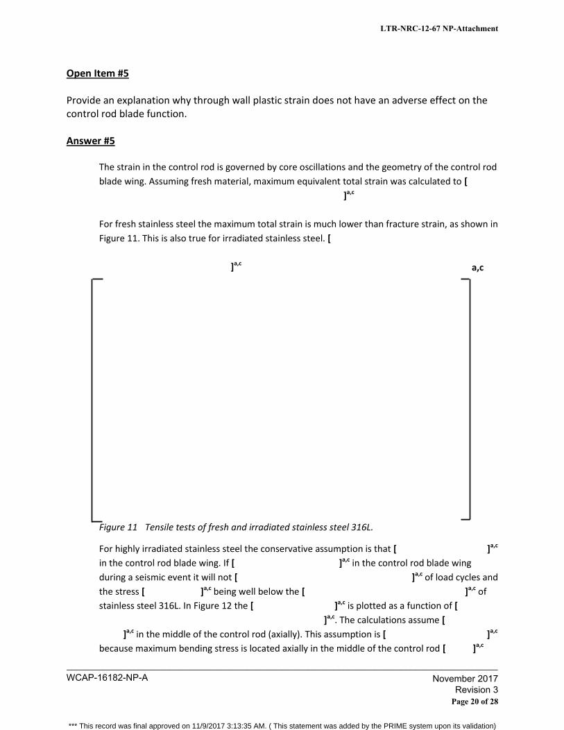
Open Item #5 Provide an explanation why through wall plastic strain does not have an adverse effect on the control rod blade function. Answer #5
The strain in the control rod is governed by core oscillations and the geometry of the control rod
blade wing. Assuming fresh material, maximum equivalent total strain was calculated to [
]a,c
For fresh stainless steel the maximum total strain is much lower than fracture strain, as shown in
Figure 11. This is also true for irradiated stainless steel. [
]a,c
Figure 11 Tensile tests of fresh and irradiated stainless steel 316L.
For highly irradiated stainless steel the conservative assumption is that [ ]a,c
in the control rod blade wing. If [ ]a,c in the control rod blade wing
during a seismic event it will not [ ]a,c of load cycles and
the stress [ ]a,c being well below the [ ]a,c of
stainless steel 316L. In Figure 12 the [ ]a,c is plotted as a function of [
]a,c. The calculations assume [
]a,c in the middle of the control rod (axially). This assumption is [ ]a,c
because maximum bending stress is located axially in the middle of the control rod [ ]a,c
a,c
LTR-NRC-12-67 NP-Attachment
Page 20 of 28
WCAP-16182-NP-A____________________________________________________________________________________
November 2017 Revision 3
*** This record was final approved on 11/9/2017 3:13:35 AM. ( This statement was added by the PRIME system upon its validation)
[
]a,c
The conclusion is that the straining of the wall will not influence the control rod worth. It is
highly unlikely that damage in the stainless steel evolves due to bending stresses [
]a,c
Therefore, there is no risk of boron loss due to bending stresses and as a result, bending stresses
will not have any impact on control rod worth.
LTR-NRC-12-67 NP-Attachment
Page 21 of 28
WCAP-16182-NP-A____________________________________________________________________________________
November 2017 Revision 3
*** This record was final approved on 11/9/2017 3:13:35 AM. ( This statement was added by the PRIME system upon its validation)
Figure 12 [ ]a,c.
5 ώ
]a,c
a,c
LTR-NRC-12-67 NP-Attachment
Page 22 of 28
WCAP-16182-NP-A____________________________________________________________________________________
November 2017 Revision 3
*** This record was final approved on 11/9/2017 3:13:35 AM. ( This statement was added by the PRIME system upon its validation)
Open Items #7 and 8 Explain that bending stresses due to seismic events are covered by the experimental testing and not included in the analysis. Provide the bending stress results comparing CR99 to CR85 to show that the experimental data from the CR85 testing is valid for the CR99. Answers #7 & #8
Bending stress in the control rod develops due to vibrations in the core during a seismic event.
During insertion of the control rod the deformation of the channels is transferred into the
control rod. Thus, bending stress in the control rod is caused by an imposed deformation and
should therefore be treated as a secondary stress.
The bending stress should be evaluated against the 3*Sm criterion if linear elastic analysis is
used. In ASME the 3*Sm criterion is used to prove that the load cycling is elastic after initial
shake down and that no cyclic deformation is built up. [
]a,c
Testing has shown that a Westinghouse control rod CR 85 can be inserted (scramed) several
times into an oscillating core [ ]a,c. The testing was performed with a
cell of 4 channels and the control rod in the center. The channels were forced to oscillate with
amplitude by applying a time varying deformation at the axial center of the channels. When the
channels were oscillating with designed amplitude and frequency the control rod was scramed
into the ‘core’. [
]a,c After
the testing it was concluded that:
1. [ ]a,c
2. [ ]a,c
3. [
]a,c
The similar geometry of CR 85 and CR 99 make the results for CR 85 valid for CR 99: a,c
LTR-NRC-12-67 NP-Attachment
Page 23 of 28
WCAP-16182-NP-A____________________________________________________________________________________
November 2017 Revision 3
*** This record was final approved on 11/9/2017 3:13:35 AM. ( This statement was added by the PRIME system upon its validation)
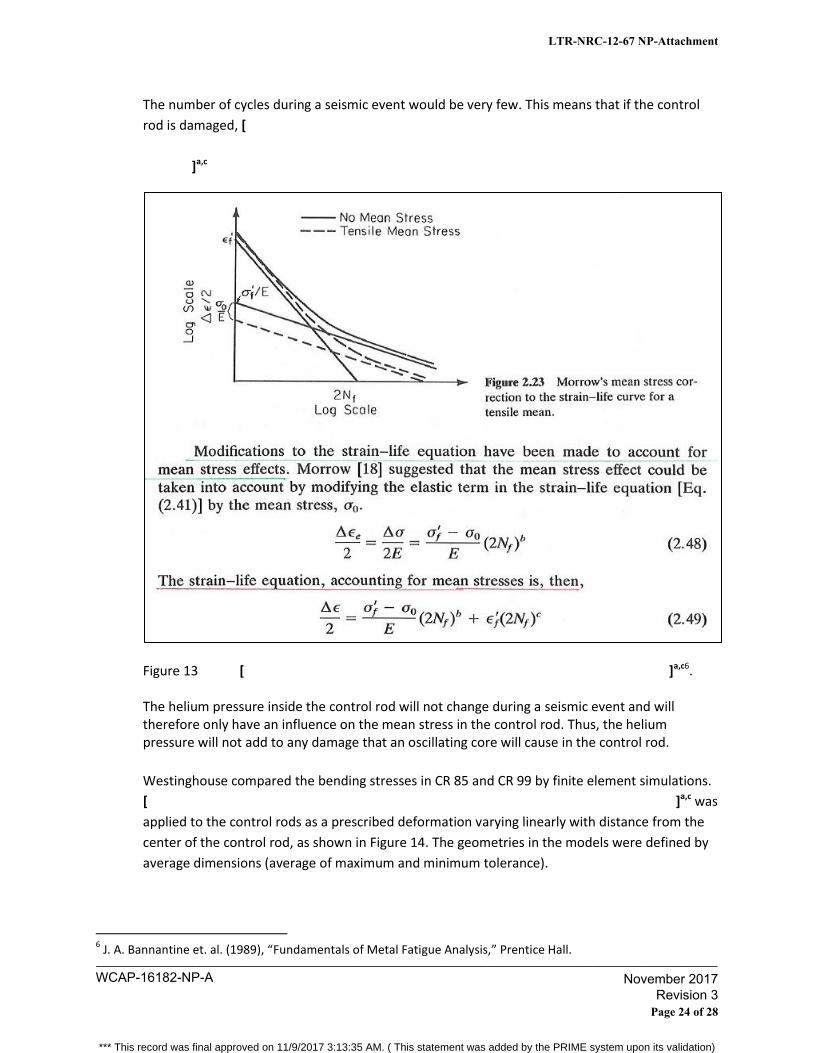
The number of cycles during a seismic event would be very few. This means that if the control
rod is damaged, [
]a,c
Figure 13 [ ]a,c6. The helium pressure inside the control rod will not change during a seismic event and will therefore only have an influence on the mean stress in the control rod. Thus, the helium pressure will not add to any damage that an oscillating core will cause in the control rod.
Westinghouse compared the bending stresses in CR 85 and CR 99 by finite element simulations.
[ ]a,c was
applied to the control rods as a prescribed deformation varying linearly with distance from the
center of the control rod, as shown in Figure 14. The geometries in the models were defined by
average dimensions (average of maximum and minimum tolerance).
6 J. A. Bannantine et. al. (1989), “Fundamentals of Metal Fatigue Analysis,” Prentice Hall.
LTR-NRC-12-67 NP-Attachment
Page 24 of 28
WCAP-16182-NP-A____________________________________________________________________________________
November 2017 Revision 3
*** This record was final approved on 11/9/2017 3:13:35 AM. ( This statement was added by the PRIME system upon its validation)
Table 6 Applied maximum deformation in finite element models.
The result from the finite element simulations show that the bending stress that evolves in the
control rod due to seismic deformation in CR 85 and CR 99 are comparable, as illustrated in
Figure 15 and Figure 16, thus proving, that the scram testing of the CR 85 into an oscillating core
is valid for CR 99.
Figure 14 Prescribed deformation varying linearly with distance to center of control rod.
7 ώ ]
a,c
a,c
a,c
LTR-NRC-12-67 NP-Attachment
Page 25 of 28
WCAP-16182-NP-A____________________________________________________________________________________
November 2017 Revision 3
*** This record was final approved on 11/9/2017 3:13:35 AM. ( This statement was added by the PRIME system upon its validation)
Figure 15 [ ]a,c equivalent stress as a function of Y-coordinate in viewed coordinate
system for both CR 99 and CR 85.
a,c
LTR-NRC-12-67 NP-Attachment
Page 26 of 28
WCAP-16182-NP-A____________________________________________________________________________________
November 2017 Revision 3
*** This record was final approved on 11/9/2017 3:13:35 AM. ( This statement was added by the PRIME system upon its validation)
Figure 16 Contour plots of [ ]a,c equivalent stress in CR 99 and CR 85.
a,c
LTR-NRC-12-67 NP-Attachment
Page 27 of 28
WCAP-16182-NP-A____________________________________________________________________________________
November 2017 Revision 3
*** This record was final approved on 11/9/2017 3:13:35 AM. ( This statement was added by the PRIME system upon its validation)
Open Item #9
Please describe the surveillance and inspection program Westinghouse has in place for its control rod blades. Answer to #9 As shown in References 1, 2 and 3, Westinghouse has been conducting and continues to conduct an
extensive surveillance program for all BWR control rod blade (CRB) designs (CR70, CR82, CR99, etc.). The
surveillance program includes, at a minimum, visual inspections to confirm the integrity of the CRBs. The
surveillance program includes additional inspections as needed, such as detailed blade measurements
(profilometry), neutron radiography and hot cell examinations to determine material behavior and
changes in properties as a function of neutron irradiation. Westinghouse pays special attention to
leading CRBs (rods that reach the highest B-10 depletion). As shown over the last forty years,
Westinghouse is committed to its rigorous surveillance program and will continue to inform the NRC of
these inspections on an ongoing basis as additional information is gathered from this surveillance
program.
References:
1. Ledergerber, G. et al., “Mechanical Performance of the Westinghouse BWR CR 99 Control Rod at
High Depeltion Levels,” 2011 Water Reactor Fuel Performance Meeting; Chengdu, China,
Sept. 11-14, 201.
2. Seltborg, P. and Jinnestrand, M., “Assessment of the Mechanical Performance of the
Westinghouse BWR Control Rod CR 99 at High Depletion Levels,” PHYSOR 2012; Knoxville, TN,
April 15-20, 2012.
3. Seltborg, P. et al., “Westinghouse BWR Control Rod CR 99 – Towards Flawless Operability,”
TopFuel 2012 – Reactor Performance Meeting; Manchester, United Kingdom,
September 2-6, 2012.
LTR-NRC-12-67 NP-Attachment
Page 28 of 28
WCAP-16182-NP-A____________________________________________________________________________________
November 2017 Revision 3
*** This record was final approved on 11/9/2017 3:13:35 AM. ( This statement was added by the PRIME system upon its validation)
(8 Westinghouse
U.S. Nuclear Regulatory Commission Document Control Desk 11555 Rockville Pike Rockville, MD 20852
Westinghouse Electric Company Nuclear Services 1 000 Westinghouse Drive Cranberry Township, Pennsylvania 16066 USA
Direct tel: (412) 374-4419 Direct fax: (724) 720-0857
e-mail: [email protected]
LTR-NRC-12-76
October 17, 2012
Subject: Supplemental Information to Open Items from NRC Audit on WCAP-16182-P-A, Revision 1, "Westinghouse BWR Control Rod CR 99 Licensing Report- Update to Mechanical Design Limits" (Proprietary/Non-Proprietary)
Enclosed are the proprietary and non-proprietary versions of, "Supplemental Information to Open Items from NRC Audit on WCAP-16182-P-A, Revision 1, 'Westinghouse BWR Control Rod CR 99 Licensing Report-Update to Mechanical Design Limits."' This audit was held at the Rockville, Maryland office on August 22, 2012. A follow-up phone call was held on October 2, 2012 to further discuss the remaining open items. The responses to these open items are contained herein.
Also enclosed is:
1. One (1) copy ofthe Application for Withholding Proprietary Information from Public Disclosure, AW-12-3556 (Non-Proprietary), with Proprietary Information Notice and Copyright Notice.
2. One (1) copy of Affidavit (Non-Proprietary).
This submittal contains proprietary information of Westinghouse Electric Company LLC. In conformance with the requirements of 10 CFR Section 2.390, as amended, of the Commission's regulations, we are enclosing with this submittal an Application for Withholding Proprietary Information from Public Disclosure and an affidavit. The affidavit sets forth the basis on which the information identified as proprietary may be withheld from public disclosure by the Commission.
Correspondence with respect to the proprietary aspects of the application for withholding or the Westinghouse affidavit should reference AW-12-3556, and should be addressed to J. A. Gresham, Manager, Regulatory Compliance, Westinghouse Electric Company, Suite 428, 1000 Westinghouse Drive, Cranberry Township, Pennsylvania 16066.
Very truly yours,
~ B. F. Maurer, Manager ABWR Licensing
Enclosures
WCAP-16182-NP-A____________________________________________________________________________________
November 2017 Revision 3
*** This record was final approved on 11/9/2017 3:13:35 AM. ( This statement was added by the PRIME system upon its validation)
WCAP-16182-NP-A____________________________________________________________________________________
November 2017 Revision 3
*** This record was final approved on 11/9/2017 3:13:35 AM. ( This statement was added by the PRIME system upon its validation)
WCAP-16182-NP-A____________________________________________________________________________________
November 2017 Revision 3
*** This record was final approved on 11/9/2017 3:13:35 AM. ( This statement was added by the PRIME system upon its validation)
AW-12-3556
2
(1) I am Manager, ABWR Licensing, in Nuclear Services, Westinghouse Electric Company LLC
(Westinghouse), and as such, I have been specifically delegated the function of reviewing the
proprietary information sought to be withheld from public disclosure in connection with nuclear
power plant licensing and rule making proceedings, and am authorized to apply for its
withholding on behalf of Westinghouse.
(2) I am making this Affidavit in conformance with the provisions of 10 CFR Section 2.390 of the
Commission's regulations and in conjunction with the Westinghouse Application for Withholding
Proprietary Information from Public Disclosure accompanying this Affidavit.
(3) I have personal knowledge of the criteria and procedures utilized by Westinghouse in designating
information as a trade secret, privileged or as confidential commercial or financial information.
(4) Pursuant to the provisions of paragraph (b)(4) of Section 2.390 of the Commission's regulations,
the following is furnished for consideration by the Commission in determining whether the
information sought to be withheld from public disclosure should be withheld.
(i) The information sought to be withheld from public disclosure is owned and has been held
in confidence by Westinghouse.
(ii) The information is of a type customarily held in confidence by Westinghouse and not
customarily disclosed to the public. Westinghouse has a rational basis for determining
the types of information customarily held in confidence by it and, in that connection,
utilizes a system to determine when and whether to hold certain types of information in
confidence. The application of that system and the substance of that system constitutes
Westinghouse policy and provides the rational basis required.
Under that system, information is held in confidence if it falls in one or more of several
types, the release of which might result in the loss of an existing or potential competitive
advantage, as follows:
(a) The information reveals the distinguishing aspects of a process (or component,
structure, tool, method, etc.) where prevention of its use by any of
WCAP-16182-NP-A____________________________________________________________________________________
November 2017 Revision 3
*** This record was final approved on 11/9/2017 3:13:35 AM. ( This statement was added by the PRIME system upon its validation)
AW-12-3556
3
Westinghouse’s competitors without license from Westinghouse constitutes a
competitive economic advantage over other companies.
(b) It consists of supporting data, including test data, relative to a process (or
component, structure, tool, method, etc.), the application of which data secures a
competitive economic advantage, e.g., by optimization or improved
marketability.
(c) Its use by a competitor would reduce his expenditure of resources or improve his
competitive position in the design, manufacture, shipment, installation, assurance
of quality, or licensing a similar product.
(d) It reveals cost or price information, production capacities, budget levels, or
commercial strategies of Westinghouse, its customers or suppliers.
(e) It reveals aspects of past, present, or future Westinghouse or customer funded
development plans and programs of potential commercial value to Westinghouse.
(f) It contains patentable ideas, for which patent protection may be desirable.
There are sound policy reasons behind the Westinghouse system which include the
following:
(a) The use of such information by Westinghouse gives Westinghouse a competitive
advantage over its competitors. It is, therefore, withheld from disclosure to
protect the Westinghouse competitive position.
(b) It is information that is marketable in many ways. The extent to which such
information is available to competitors diminishes the Westinghouse ability to
sell products and services involving the use of the information.
(c) Use by our competitor would put Westinghouse at a competitive disadvantage by
reducing his expenditure of resources at our expense.
WCAP-16182-NP-A____________________________________________________________________________________
November 2017 Revision 3
*** This record was final approved on 11/9/2017 3:13:35 AM. ( This statement was added by the PRIME system upon its validation)
AW-12-3556
4
(d) Each component of proprietary information pertinent to a particular competitive
advantage is potentially as valuable as the total competitive advantage. If
competitors acquire components of proprietary information, any one component
may be the key to the entire puzzle, thereby depriving Westinghouse of a
competitive advantage.
(e) Unrestricted disclosure would jeopardize the position of prominence of
Westinghouse in the world market, and thereby give a market advantage to the
competition of those countries.
(f) The Westinghouse capacity to invest corporate assets in research and
development depends upon the success in obtaining and maintaining a
competitive advantage.
(iii) The information is being transmitted to the Commission in confidence and, under the
provisions of 10 CFR Section 2.390, it is to be received in confidence by the
Commission.
(iv) The information sought to be protected is not available in public sources or available
information has not been previously employed in the same original manner or method to
the best of our knowledge and belief.
(v) The proprietary information sought to be withheld in this submittal is that which is
appropriately marked in LTR-NRC-12-76 P-Attachment, “Supplemental Information on
Open Items from NRC Audit on WCAP-16182-P-A, Revision 1, ‘Westinghouse BWR
Control Rod CR 99 Licensing Report – Update to Mechanical Design Limits’”
(Proprietary), for submittal to the Commission, being transmitted by Westinghouse letter,
LTR-NRC-12-76, and Application for Withholding Proprietary Information from Public
Disclosure, to the Document Control Desk. The proprietary information as submitted by
Westinghouse is that associated with Westinghouse’s request for NRC approval of
WCAP-16182-P-A, Revision 1, and may be used only for that purpose.
WCAP-16182-NP-A____________________________________________________________________________________
November 2017 Revision 3
*** This record was final approved on 11/9/2017 3:13:35 AM. ( This statement was added by the PRIME system upon its validation)

AW-12-3556
5
This information is part of that which will enable Westinghouse to:
(a) Obtain NRC approval of WCAP-16182-P-A, Revision 1, “Westinghouse BWR
Control Rod CR 99 Licensing Report – Update to Mechanical Design Limits.”
(b) Extend the mechanical lifetime of Westinghouse BWR control blades.
Further this information has substantial commercial value as follows:
(a) Westinghouse plans to sell the use of this information to its customers for the
purpose of obtaining license changes.
(b) The information requested to be withheld reveals the distinguishing aspects of a
methodology which was developed by Westinghouse.
Public disclosure of this proprietary information is likely to cause substantial harm to the
competitive position of Westinghouse because it would enhance the ability of
competitors to provide similar fuel designs and licensing defense services for commercial
power reactors without commensurate expenses. Also, public disclosure of the
information would enable others to use the information to meet NRC requirements for
licensing documentation without purchasing the right to use the information.
The development of the technology described in part by the information is the result of
applying the results of many years of experience in an intensive Westinghouse effort and
the expenditure of a considerable sum of money.
In order for competitors of Westinghouse to duplicate this information, similar technical
programs would have to be performed and a significant manpower effort, having the
requisite talent and experience, would have to be expended.
Further the deponent sayeth not.
WCAP-16182-NP-A____________________________________________________________________________________
November 2017 Revision 3
*** This record was final approved on 11/9/2017 3:13:35 AM. ( This statement was added by the PRIME system upon its validation)

Proprietary Information Notice
Transmitted herewith are proprietary and/or non-proprietary versions of documents furnished to the NRC in connection with requests for generic and/or plant-specific review and approval. In order to conform to the requirements of 10 CFR 2.390 of the Commission's regulations concerning the protection of proprietary information so submitted to the NRC, the information which is proprietary in the proprietary versions is contained within brackets, and where the proprietary information has been deleted in the non-proprietary versions, only the brackets remain (the information that was contained within the brackets in the proprietary versions having been deleted). The justification for claiming the information so designated as proprietary is indicated in both versions by means of lower case letters (a) through (f) located as a superscript immediately following the brackets enclosing each item of information being identified as proprietary or in the margin opposite such information. These lower case letters refer to the types of information Westinghouse customarily holds in confidence identified in Sections (4)(ii)(a) through (4)(ii)(f) of the affidavit accompanying this transmittal pursuant to 10 CFR 2.390(b)(1).
Copyright Notice The reports transmitted herewith each bear a Westinghouse copyright notice. The NRC is permitted to make the number of copies of the information contained in these reports which are necessary for its internal use in connection with generic and plant-specific reviews and approvals as well as the issuance, denial, amendment, transfer, renewal, modification, suspension, revocation, or violation of a license, permit, order, or regulation subject to the requirements of 10 CFR 2.390 regarding restrictions on public disclosure to the extent such information has been identified as proprietary by Westinghouse, copyright protection notwithstanding. With respect to the non-proprietary versions of these reports, the NRC is permitted to make the number of copies beyond those necessary for its internal use which are necessary in order to have one copy available for public viewing in the appropriate docket files in the public document room in Washington, DC and in local public document rooms as may be required by NRC regulations if the number of copies submitted is insufficient for this purpose. Copies made by the NRC must include the copyright notice in all instances and the proprietary notice if the original was identified as proprietary.
WCAP-16182-NP-A____________________________________________________________________________________
November 2017 Revision 3
*** This record was final approved on 11/9/2017 3:13:35 AM. ( This statement was added by the PRIME system upon its validation)
Westinghouse Non-Proprietary Class 3
LTR-NRC-12-76 NP-Attachment TAC No. ME2630
Supplemental Information on Open Items from NRC Audit on WCAP-16182-P-A, Revision 1, “Westinghouse BWR Control Rod CR 99 Licensing Report – Update to Mechanical Design Limits”
(Non-Proprietary)
October 2012
Westinghouse Electric Company 1000 Westinghouse Drive
Cranberry Township, PA 16066
© 2012 Westinghouse Electric Company LLC All Rights Reserved
WCAP-16182-NP-A____________________________________________________________________________________
November 2017 Revision 3
*** This record was final approved on 11/9/2017 3:13:35 AM. ( This statement was added by the PRIME system upon its validation)
Item 1
Provide a summary of the number of control rod blades (CRBs) that have been inspected and were found to have cracks. Provide information on the number of these rods that have experienced B4C losses. This should include all Westinghouse designed CRBs.
Item 1 Response
To date, Westinghouse has delivered 6348 control rods and has performed more than [ ]a,c inspections. From the onset of Westinghouse control rod operation, major inspection programs have been performed. The number of delivered and number of inspections of five Westinghouse BWR control rods designs are shown in Figure 1.
The first design, CR 70, was an all-B4C control rod with horizontally drilled absorber holes in stainless steel plates to contain the absorber material; the same basic design as all Westinghouse Control Rod Blades (CRBs). For CR 70, the absorber material was boron carbide powder and the blade wings were made of 304L stainless steel.
Since the performance of the CR 70 has been inspected from the beginning of operation, more than 40 years of experiences and observations exist. In addition to inspections performed during the operating lifetime of a CRB, all CR 70s that have been replaced in the Nordic (Swedish and Finnish) BWRs have been inspected prior to disposal. Thus today there have been [ ]a,c inspections of CR 70. Several of the CR 70 control rods have been inspected multiple times.
During these inspections, cracks were observed in [ ]a,c CR 70s. To determine if the observed cracks resulted in any significant loss of boron carbide powder, [ ]a,c blade wings were examined by neutron radiography. The results of these examinations showed there was no significant boron carbide loss in any case. Therefore, no reduction in reactivity worth resulted from these cracks.
Because of the design of these blades, if a large enough crack existed that leakage did occur, the leakage would be minimal. Each individual horizontal hole acts as a small compartment with limited interaction with the other horizontal holes. A Westinghouse control rod has about [ ]a,c absorber holes. Therefore, in the unlikely event that a crack at a hole propagated to the point where wash-out occurred, the possible loss of the boron carbide would be limited to a single compartment where the crack occurred, which will have a negligible impact on the reactivity worth even if all the boron carbide in a given hole is lost.
However, because of the absorber design in the CR 99, the possibility for wash-out has been eliminated. The CR 99 contains 100% dense hot isostatic pressed (HIP) boron carbide pins as the absorber material in the holes. Additionally, the CR 99 uses the same basic blade design, with horizontally drilled absorber holes in 316L stainless steel1. CR 99 control blades with
1 [
]a,c
LTR-NRC-12-76 NP-Attachment
WCAP-16182-NP-A____________________________________________________________________________________
November 2017 Revision 3
*** This record was final approved on 11/9/2017 3:13:35 AM. ( This statement was added by the PRIME system upon its validation)
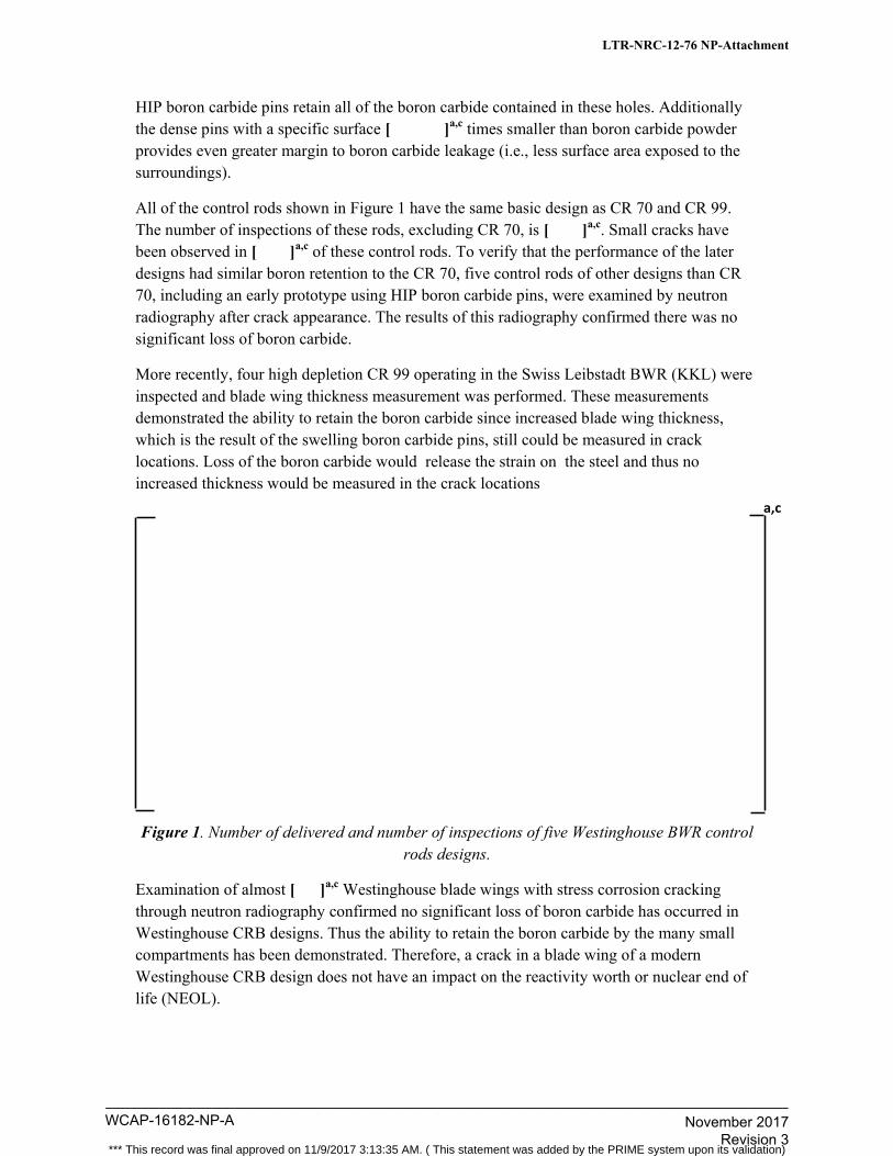
HIP boron carbide pins retain all of the boron carbide contained in these holes. Additionally the dense pins with a specific surface [ ]a,c times smaller than boron carbide powder provides even greater margin to boron carbide leakage (i.e., less surface area exposed to the surroundings).
All of the control rods shown in Figure 1 have the same basic design as CR 70 and CR 99. The number of inspections of these rods, excluding CR 70, is [ ]a,c. Small cracks have been observed in [ ]a,c of these control rods. To verify that the performance of the later designs had similar boron retention to the CR 70, five control rods of other designs than CR 70, including an early prototype using HIP boron carbide pins, were examined by neutron radiography after crack appearance. The results of this radiography confirmed there was no significant loss of boron carbide.
More recently, four high depletion CR 99 operating in the Swiss Leibstadt BWR (KKL) were inspected and blade wing thickness measurement was performed. These measurements demonstrated the ability to retain the boron carbide since increased blade wing thickness, which is the result of the swelling boron carbide pins, still could be measured in crack locations. Loss of the boron carbide would release the strain on the steel and thus no increased thickness would be measured in the crack locations
Figure 1. Number of delivered and number of inspections of five Westinghouse BWR control rods designs.
Examination of almost [ ]a,c Westinghouse blade wings with stress corrosion cracking through neutron radiography confirmed no significant loss of boron carbide has occurred in Westinghouse CRB designs. Thus the ability to retain the boron carbide by the many small compartments has been demonstrated. Therefore, a crack in a blade wing of a modern Westinghouse CRB design does not have an impact on the reactivity worth or nuclear end of life (NEOL).
a,c
LTR-NRC-12-76 NP-Attachment
WCAP-16182-NP-A____________________________________________________________________________________
November 2017 Revision 3
*** This record was final approved on 11/9/2017 3:13:35 AM. ( This statement was added by the PRIME system upon its validation)
Item 2
Provide background information explaining the origins of the data provided in Figure 1-2 and Figure 1-3 in the response to Follow-up RAI-1. Also provide justification as to why this data is applicable to the CR 99.
Item 2 Response
As previously discussed with the NRC staff, the BWR CRBs [ ]a,c The helium release discussion included in WCAP-16182 is to provide a
defense-in-depth analysis to verify the integrity of the CRBs. [
]a,c
In Figure 1-2 of the response to Follow-up RAI-1, additional helium release data was displayed. The applicability of this data is mainly understood from evaluating, irradiation temperature and grain size. Increasing temperature results in a higher diffusion rate of helium atoms in the pellet and smaller grain size causes the helium atoms to reach the grain boundaries faster. When this occurs, the release of helium from grains to free volume is increased.
The irradiation in the study referenced in the response to Follow-up RAI-1 was performed in a fast reactor. It is shown that the irradiation temperature has been well above 500°C (>932°F).
The grain size in the pellets was less than 5 m. In relation to the CR 99 pellets, where the
irradiation temperature is below 500°C and the grain size is below [ ]a,c m, it is evident that a higher irradiation temperature as well as a smaller grain size makes the referenced data conservative relative to the helium release for the boron carbide pellets in the CR 99. The referenced study covers 10B-depletion levels up to 100% in natural boron carbide. Up to and well above an irradiation level corresponding to the nuclear end of life of CR 99, the helium release is linearly increasing at a level covered by the stress analysis calculations.
Furthermore, the neutron spectrum in the fast reactor is harder than the spectrum in a BWR. This harder spectrum is more damaging to the boron carbide structure, promoting the release of helium and thus making the release data of helium more abundant than found in the BWR environment of a thermal reactor.
The swelling data in Figure 1-3 of the response to Follow-up RAI-1 is based on density measurements from irradiated boron carbide pellets.
The swelling of the boron carbide pellets is not dependent on the irradiation conditions. It is instead dependent on the helium retention. [
]a,c
LTR-NRC-12-76 NP-Attachment
WCAP-16182-NP-A____________________________________________________________________________________
November 2017 Revision 3
*** This record was final approved on 11/9/2017 3:13:35 AM. ( This statement was added by the PRIME system upon its validation)
[ ]a,c thus the swelling data is applicable to and supports the CR 99 design.
Blade wing swelling data from Westinghouse control rods is based on the increase in thickness of the control rod blade wings where swelling pellets are straining the stainless steel. This swelling is a combination of solid swelling and the development of porosities in the pellet. The fact that Westinghouse can predict the level of 10B depletion that results in pellet-to-blade contact and blade swelling as a function of 10B depletion makes the equation of solid swelling provided in the response applicable to the dense CR 99 boron carbide pellet.
LTR-NRC-12-76 NP-Attachment
WCAP-16182-NP-A____________________________________________________________________________________
November 2017 Revision 3
*** This record was final approved on 11/9/2017 3:13:35 AM. ( This statement was added by the PRIME system upon its validation)
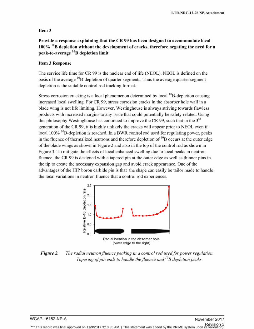
Item 3
Provide a response explaining that the CR 99 has been designed to accommodate local 100% 10B depletion without the development of cracks, therefore negating the need for a peak-to-average 10B depletion limit.
Item 3 Response
The service life time for CR 99 is the nuclear end of life (NEOL). NEOL is defined on the basis of the average 10B-depletion of quarter segments. Thus the average quarter segment depletion is the suitable control rod tracking format.
Stress corrosion cracking is a local phenomenon determined by local 10B-depletion causing increased local swelling. For CR 99, stress corrosion cracks in the absorber hole wall in a blade wing is not life limiting. However, Westinghouse is always striving towards flawless products with increased margins to any issue that could potentially be safety related. Using this philosophy Westinghouse has continued to improve the CR 99, such that in the 3rd generation of the CR 99, it is highly unlikely the cracks will appear prior to NEOL even if local 100% 10B-depletion is reached. In a BWR control rod used for regulating power, peaks in the fluence of thermalized neutrons and therefore depletion of 10B occurs at the outer edge of the blade wings as shown in Figure 2 and also in the top of the control rod as shown in Figure 3. To mitigate the effects of local enhanced swelling due to local peaks in neutron fluence, the CR 99 is designed with a tapered pin at the outer edge as well as thinner pins in the tip to create the necessary expansion gap and avoid crack appearance. One of the advantages of the HIP boron carbide pin is that the shape can easily be tailor made to handle the local variations in neutron fluence that a control rod experiences.
Figure 2. The radial neutron fluence peaking in a control rod used for power regulation. Tapering of pin ends to handle the fluence and 10B depletion peaks.
0.0
0.5
1.0
1.5
2.0
2.5
Rel
ativ
e B
-10
dep
letio
n ra
te
Radial location in the absorber hole(outer edge to the right)
LTR-NRC-12-76 NP-Attachment
WCAP-16182-NP-A____________________________________________________________________________________
November 2017 Revision 3
*** This record was final approved on 11/9/2017 3:13:35 AM. ( This statement was added by the PRIME system upon its validation)
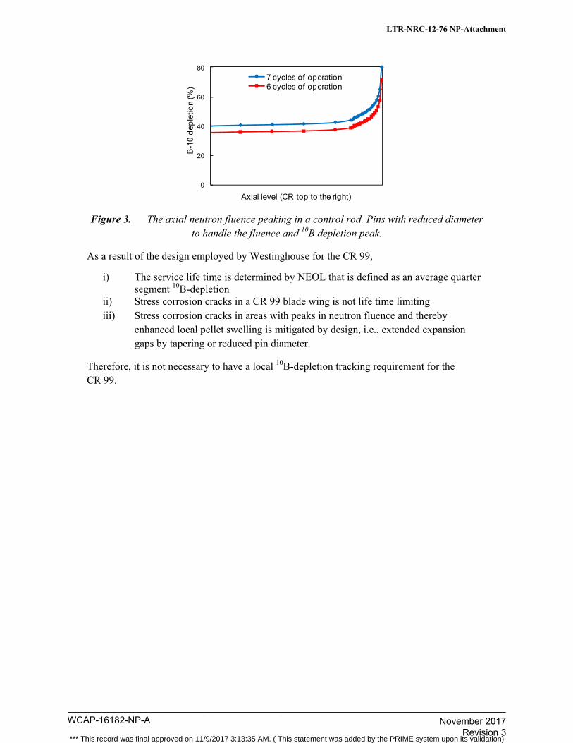
Figure 3. The axial neutron fluence peaking in a control rod. Pins with reduced diameter to handle the fluence and 10B depletion peak.
As a result of the design employed by Westinghouse for the CR 99,
i) The service life time is determined by NEOL that is defined as an average quarter segment 10B-depletion
ii) Stress corrosion cracks in a CR 99 blade wing is not life time limiting iii) Stress corrosion cracks in areas with peaks in neutron fluence and thereby
enhanced local pellet swelling is mitigated by design, i.e., extended expansion gaps by tapering or reduced pin diameter.
Therefore, it is not necessary to have a local 10B-depletion tracking requirement for the CR 99.
0
20
40
60
80
B-1
0 d
eple
tion
(%)
Axial level (CR top to the right)
7 cycles of operation6 cycles of operation
LTR-NRC-12-76 NP-Attachment
WCAP-16182-NP-A____________________________________________________________________________________
November 2017 Revision 3
*** This record was final approved on 11/9/2017 3:13:35 AM. ( This statement was added by the PRIME system upon its validation)
Westinghouse Non-Proprietary Class 3
in ouse
U.S. Nuclear Regulatory Commission Document Control Desk 11555 Rockville Pike Rockville, MD 20852
Westinghouse Electric Company 1 000 Westinghouse Drive Cranberry Township, Pennsylvania 16066 USA
Direct tel: (412) 374-4643 Direct fax: (724) 940-8560
e-mail: [email protected]
LTR-NRC-16-40
June 15, 2016
Subject: Meeting Minutes for the NRC Combined Audit of WCAP-16182-P, Rev. 2, "Westinghouse BWR Control Rod CR 99 Licensing Report - Update to Mechanical Design Limits," and WCAP-17769-P, Rev. 0, "Reference Fuel Design SVEA-96 Optima3" (Non-Proprietary)
'Attached are Westinghouse meeting minutes for the NRC combined audit ofWCAP-16182-P, Rev. 2, "Westinghouse BWR Control Rod CR 99 Licensing Report- Update to Mechanical Design Limits," and WCAP-17769-P, Rev. 0, "Reference Fuel Design SVEA-96 Optima3."
This submittal does not contain proprietary information of Westinghouse Electric Company LLC.
Correspondence should be addressed to James A. Gresham, Manager, Regulatory Compliance, Westinghouse Electric Company, 1000 Westinghouse Drive, Building 3, Suite 310, Cranberry Township, Pennsylvania 16066.
Enclosures cc: Ekaterina Lenning
Kevin Hsueh
Regulatory Compliance
WCAP-16182-NP-A____________________________________________________________________________________
November 2017 Revision 3
*** This record was final approved on 11/9/2017 3:13:35 AM. ( This statement was added by the PRIME system upon its validation)
Westinghouse Non-Proprietary Class 3
Attachment to LTR-NRC-16-40
© 2016 Westinghouse Electric Company LLC. All Rights Reserved
- 1 -
Meeting Minutes for the NRC Combined Audit of WCAP-16182-P, Rev. 2, “Westinghouse BWR Control Rod CR 99 Licensing Report –
Update to Mechanical Design Limits,” and WCAP-17769-P, Rev. 0, “Reference Fuel Design SVEA-96 Optima3”
Purpose To discuss the audit topics identified in the NRC Audit Plan related to the NRC reviews of WCAP-16182-P, Rev. 2, “Westinghouse BWR Control Rod CR 99 Licensing Report – Update to Mechanical Design Limits,” and WCAP-17769-P, Rev. 0, “Reference Fuel Design-n SVEA-96 Optima3.” The desired outcome of the audit was to reach a common understanding regarding the audit topics which will enable completion of a successful review for each of these topical reports going forward. An additional objective was to review draft responses to the draft RAIs received on WCAP-17769-P. Date / Location May 17-20, 2016 Westinghouse Nuclear Regulatory Affairs Office, Rockville, MD Attendees U.S. Nuclear Regulatory Commission (NRC) Westinghouse Kate Lenning All Ed Mercier All Mathew Panicker 5/17, 18, 19 Anghel Enica All Daniel Beacon 5/18 Magnus Jinnestrand All Josh Whitman 5/19, 20 Roger Brändström All Jeremy Dean 5/20 closeout Brad Maurer All Patricia Quaglia 5/20 Pacific Northwest National Laboratory (PNNL) Kaj Thorselius 5/20 Nicholas Klymyshyn All Paul Blair 5/20 Walter Luscher 5/19, 20 Pascal Jourdain 5/20 Tommy Gustafsson 5/20 Eric Frantz 5/20 Stephen Heagy 5/20 Dan Menoher 5/20 WCAP-16182-P (CR 99 Control Rods) Audit Items – May 17, 18 The meeting included a presentation and detailed discussion of the design of the CR 99 Generation 3 control rods, and the differences between the Generation 3 and previously licensed Generation 2 control rods. The Westinghouse responses to the CR 99 audit items were reviewed and discussed. Modeling and results presented in the reports and calculation packages were reviewed and discussed. The documents reviewed were those requested in audit item 3, as well as additional documents requested during the course of the audit.
WCAP-16182-NP-A____________________________________________________________________________________
November 2017 Revision 3
*** This record was final approved on 11/9/2017 3:13:35 AM. ( This statement was added by the PRIME system upon its validation)
Westinghouse Non-Proprietary Class 3
Attachment to LTR-NRC-16-40
- 2 -
Open items Identified Clarification of design requirements with regard to ASME Class 1 rules, including explanation of the
1.1 factor used in nonlinear analysis. Clarification needed regarding the treatment of cracking in the design. Adequacy of the surveillance plan – how is observed cracking addressed with regard to material
integrity Adherence to Appendix F for analysis of SSE loading Treatment of SSE loads in the Level D analysis. Actions resulting from Open Items A number of areas were identified in WCAP-16182 where changes and clarifications will be made to
address various audit items (Action: Westinghouse) Collapse load analysis for SSE to be performed to demonstrate compliance with Appendix F limits.
Modeling, approach, and LTR content were discussed. (Action: Westinghouse) Surveillance plan as presented in WCAP-16182 to be reviewed (Action: NRC) Documents reviewed SES 12-091, Rev. 1, “Methodology of Helium Pressure Calculation in Westinghouse CR 99 BWR
Control Rods with HIPed pins by Statistical Models” SES 15-005, Rev. 0, “Structural Verification of Control Rod CR99 Generation 3 for BWR/2-4 and
BWR/6 Reactors with S- & D- Lattice” SES 15-011, Rev. 0, “Modeling of CR99 Control Rod Blade Swelling” SES 15-013, Rev. 0, “Structural Verification of Control Rod CR99 Generation 3 for BWR4/5
Reactors with C-Lattice” WCAP-17769-P (SVEA-96 Optima3) Audit Items – May 19, and Draft RAIs – May 20 The meeting included a presentation and detailed discussion of the design of the SVEA-96 Optima3 fuel assembly, and the differences between the SVEA-96 Optima3 assembly and previously licensed Optima2. The Westinghouse responses to the SVEA-96 Optima3 audit items were reviewed and discussed. Reports and calculation packages were identified by Westinghouse in response to audit Items 1 and 2. Modeling and analysis results presented in the reports and calculation packages were reviewed and discussed. Additional documents were also reviewed as requested during the course of the audit. Also, Westinghouse draft RAI responses to the NRC’s draft RAIs were reviewed (responses to 11 of the 12 RAIs were reviewed; the response to RAI-09 was not available for the audit). The RAIs are in the concurrence process within NRC. Open items Identified Use of Von Mises criteria. SSE as AOO (no, but OBE is). Source of Table 4.3.3-1 values. Question regarding OBE (Operating Basis Earthquake) analysis. Actions resulting from Open Items A number of areas were identified in WCAP-17769 where changes and clarifications will be made to
address various audit items and RAI responses (Action: Westinghouse) Additional question was identified: per NRC guidance, OBE is an AOO (anticipated operational
occurrence). (Action: Westinghouse) o Identify the grid crush strength at in-reactor BOL and EOL conditions.
WCAP-16182-NP-A____________________________________________________________________________________
November 2017 Revision 3
*** This record was final approved on 11/9/2017 3:13:35 AM. ( This statement was added by the PRIME system upon its validation)
Westinghouse Non-Proprietary Class 3
Attachment to LTR-NRC-16-40
- 3 -
o Identify the lateral load capacity of all SVEA-96 Optima3 components under anticipated OBE loading conditions at BOL and EOL.
o Identify the range of lateral loads that are anticipated for all SVEA-96 Optima3 components under OBE conditions at BOL and EOL.
Documents reviewed SES 12-053, Rev. 1, “Plastic Analysis of SVEA-96 Fuel Channel Subjected to Internal Overpressure” SES 12-274, Rev. 1, “Stress Evaluation of Cladding in Light Water Reactors” SES 13-014, Rev. 2, “Stress Analysis of SVEA-96 Optima3 Fuel Rod” BTA 07-0053, Rev. 1, “SVEA-96 Optima3 Spacer Cell Mounted with a Fuel Rod. Analysis of
Stresses and Displacements” BU 97-091, Rev. 3, “STAV7 Model Description” BK 93-779, Rev. 1, “Channel Fatigue – Evaluation of Low Cycle Fatigue for Fuel Channels” BTK 04-077, Rev 1, “Lateral Load Cycling Test of Optima3 Spacer Verifying Test” Summary All audit items for WCAP-16182, Rev. 2 (CR 99) and WCAP-17769, Rev. 0 (SVEA-96 Optima3) were reviewed. Appropriate follow-on actions were identified to resolve remaining open items. Also, 11 of the 12 draft RAIs for WCAP-17769 were reviewed. Specific changes identified will be addressed in the final RAI responses after the RAIs are formally issued. Changes to both WCAP-16182 and WCAP-17769 were identified to address various audit items and several of the RAIs, as appropriate. Westinghouse will formally provide the audit presentation materials to the NRC. Westinghouse will also provide an audit summary (meeting minutes) to the NRC.
WCAP-16182-NP-A____________________________________________________________________________________
November 2017 Revision 3
*** This record was final approved on 11/9/2017 3:13:35 AM. ( This statement was added by the PRIME system upon its validation)