wave optics chapter ten wave optics - national · pdf filewave optics chapter ten wave optics...
TRANSCRIPT

351
Wave Optics
Chapter Ten
WAVE OPTICS
10.1 INTRODUCTION
In 1637 Descartes gave the corpuscular model of light and derived Snell’slaw. It explained the laws of reflection and refraction of light at an interface.The corpuscular model predicted that if the ray of light (on refraction)bends towards the normal then the speed of light would be greater in thesecond medium. This corpuscular model of light was further developedby Isaac Newton in his famous book entitled OPTICKS and because ofthe tremendous popularity of this book, the corpuscular model is veryoften attributed to Newton.
In 1678, the Dutch physicist Christiaan Huygens put forward thewave theory of light – it is this wave model of light that we will discuss inthis chapter. As we will see, the wave model could satisfactorily explainthe phenomena of reflection and refraction; however, it predicted that onrefraction if the wave bends towards the normal then the speed of lightwould be less in the second medium. This is in contradiction to theprediction made by using the corpuscular model of light. It was muchlater confirmed by experiments where it was shown that the speed oflight in water is less than the speed in air confirming the prediction of thewave model; Foucault carried out this experiment in 1850.
The wave theory was not readily accepted primarily because ofNewton’s authority and also because light could travel through vacuum
© NCERT
not to
be re
publi
shed
Physics
352
and it was felt that a wave would always require a medium to propagatefrom one point to the other. However, when Thomas Young performedhis famous interference experiment in 1801, it was firmly establishedthat light is indeed a wave phenomenon. The wavelength of visiblelight was measured and found to be extremely small; for example, thewavelength of yellow light is about 0.5 µm. Because of the smallnessof the wavelength of visible light (in comparison to the dimensions oftypical mirrors and lenses), light can be assumed to approximatelytravel in straight lines. This is the field of geometrical optics, which wehad discussed in the previous chapter. Indeed, the branch of optics inwhich one completely neglects the finiteness of the wavelength is calledgeometrical optics and a ray is defined as the path of energypropagation in the limit of wavelength tending to zero.
After the interference experiment of Young in 1801, for the next 40years or so, many experiments were carried out involving theinterference and diffraction of lightwaves; these experiments could onlybe satisfactorily explained by assuming a wave model of light. Thus,around the middle of the nineteenth century, the wave theory seemedto be very well established. The only major difficulty was that since itwas thought that a wave required a medium for its propagation, howcould light waves propagate through vacuum. This was explainedwhen Maxwell put forward his famous electromagnetic theory of light.Maxwell had developed a set of equations describing the laws ofelectricity and magnetism and using these equations he derived whatis known as the wave equation from which he predicted the existenceof electromagnetic waves*. From the wave equation, Maxwell couldcalculate the speed of electromagnetic waves in free space and he foundthat the theoretical value was very close to the measured value of speedof l ight. From this, he propounded that l ight must be an
electromagnetic wave. Thus, according to Maxwell, light waves areassociated with changing electric and magnetic fields; changing electricfield produces a time and space varying magnetic field and a changingmagnetic field produces a time and space varying electric field. Thechanging electric and magnetic fields result in the propagation ofelectromagnetic waves (or light waves) even in vacuum.
In this chapter we will first discuss the original formulation of theHuygens principle and derive the laws of reflection and refraction. InSections 10.4 and 10.5, we will discuss the phenomenon of interferencewhich is based on the principle of superposition. In Section 10.6 wewill discuss the phenomenon of diffraction which is based on Huygens-Fresnel principle. Finally in Section 10.7 we will discuss thephenomenon of polarisation which is based on the fact that the lightwaves are transverse electromagnetic waves.
* Maxwell had predicted the existence of electromagnetic waves around 1855; itwas much later (around 1890) that Heinrich Hertz produced radiowaves in thelaboratory. J.C. Bose and G. Marconi made practical applications of the Hertzian
waves
© NCERT
not to
be re
publi
shed
353
Wave Optics
10.2 HUYGENS PRINCIPLE
We would first define a wavefront: when we drop a small stone on a calmpool of water, waves spread out from the point of impact. Every point onthe surface starts oscillating with time. At any instant, a photograph ofthe surface would show circular rings on which the disturbance ismaximum. Clearly, all points on such a circle are oscillating in phasebecause they are at the same distance from the source. Such a locus ofpoints, which oscillate in phase is called a wavefront ; thus a wavefront
is defined as a surface of constant phase. The speed with which thewavefront moves outwards from the source is called the speed of thewave. The energy of the wave travels in a direction perpendicular to thewavefront.
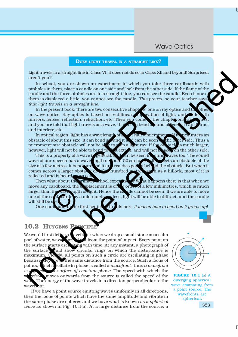
If we have a point source emitting waves uniformly in all directions,then the locus of points which have the same amplitude and vibrate inthe same phase are spheres and we have what is known as a sphericalwave as shown in Fig. 10.1(a). At a large distance from the source, a
DOES LIGHT TRAVEL IN A STRAIGHT LINE?
Light travels in a straight line in Class VI; it does not do so in Class XII and beyond! Surprised,aren’t you?
In school, you are shown an experiment in which you take three cardboards withpinholes in them, place a candle on one side and look from the other side. If the flame of thecandle and the three pinholes are in a straight line, you can see the candle. Even if one ofthem is displaced a little, you cannot see the candle. This proves, so your teacher says,that light travels in a straight line.
In the present book, there are two consecutive chapters, one on ray optics and the otheron wave optics. Ray optics is based on rectilinear propagation of light, and deals withmirrors, lenses, reflection, refraction, etc. Then you come to the chapter on wave optics,and you are told that light travels as a wave, that it can bend around objects, it can diffractand interfere, etc.
In optical region, light has a wavelength of about half a micrometre. If it encounters anobstacle of about this size, it can bend around it and can be seen on the other side. Thus amicrometre size obstacle will not be able to stop a light ray. If the obstacle is much larger,however, light will not be able to bend to that extent, and will not be seen on the other side.
This is a property of a wave in general, and can be seen in sound waves too. The soundwave of our speech has a wavelength of about 50cm to 1 m. If it meets an obstacle of thesize of a few metres, it bends around it and reaches points behind the obstacle. But when itcomes across a larger obstacle of a few hundred metres, such as a hillock, most of it isreflected and is heard as an echo.
Then what about the primary school experiment? What happens there is that when wemove any cardboard, the displacement is of the order of a few millimetres, which is muchlarger than the wavelength of light. Hence the candle cannot be seen. If we are able to moveone of the cardboards by a micrometer or less, light will be able to diffract, and the candlewill still be seen.
One could add to the first sentence in this box: It learns how to bend as it grows up!
FIGURE 10.1 (a) Adiverging spherical
wave emanating froma point source. The
wavefronts arespherical.
© NCERT
not to
be re
publi
shed
Physics
354
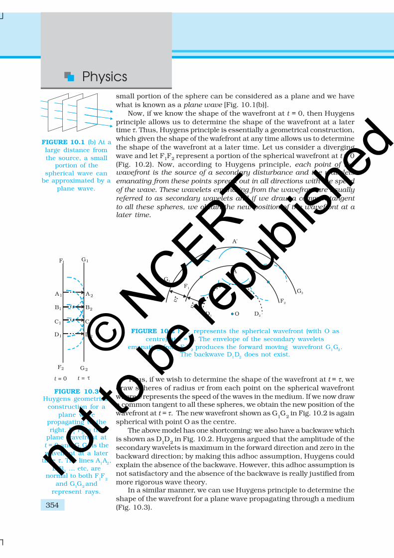
small portion of the sphere can be considered as a plane and we havewhat is known as a plane wave [Fig. 10.1(b)].
Now, if we know the shape of the wavefront at t = 0, then Huygensprinciple allows us to determine the shape of the wavefront at a latertime τ. Thus, Huygens principle is essentially a geometrical construction,which given the shape of the wafefront at any time allows us to determinethe shape of the wavefront at a later time. Let us consider a divergingwave and let F1F2 represent a portion of the spherical wavefront at t = 0(Fig. 10.2). Now, according to Huygens principle, each point of thewavefront is the source of a secondary disturbance and the wavelets
emanating from these points spread out in all directions with the speed
of the wave. These wavelets emanating from the wavefront are usually
referred to as secondary wavelets and if we draw a common tangent
to all these spheres, we obtain the new position of the wavefront at alater time.
FIGURE 10.1 (b) At alarge distance fromthe source, a small
portion of thespherical wave can
be approximated by aplane wave.
FIGURE 10.2 F1F
2 represents the spherical wavefront (with O as
centre) at t = 0. The envelope of the secondary waveletsemanating from F1F2 produces the forward moving wavefront G1G2.
The backwave D1D2 does not exist.
Thus, if we wish to determine the shape of the wavefront at t = τ, wedraw spheres of radius vτ from each point on the spherical wavefrontwhere v represents the speed of the waves in the medium. If we now drawa common tangent to all these spheres, we obtain the new position of thewavefront at t = τ. The new wavefront shown as G
1G
2 in Fig. 10.2 is again
spherical with point O as the centre.The above model has one shortcoming: we also have a backwave which
is shown as D1D
2 in Fig. 10.2. Huygens argued that the amplitude of the
secondary wavelets is maximum in the forward direction and zero in thebackward direction; by making this adhoc assumption, Huygens couldexplain the absence of the backwave. However, this adhoc assumption isnot satisfactory and the absence of the backwave is really justified frommore rigorous wave theory.
In a similar manner, we can use Huygens principle to determine theshape of the wavefront for a plane wave propagating through a medium(Fig. 10.3).
FIGURE 10.3Huygens geometrical
construction for aplane wave
propagating to theright. F1 F2 is the
plane wavefront att = 0 and G1G2 is thewavefront at a later
time τ. The lines A1A2,B1B2 … etc, are
normal to both F1F
2
and G1G2 andrepresent rays.
© NCERT
not to
be re
publi
shed
355
Wave Optics
10.3 REFRACTION AND REFLECTION OF
PLANE WAVES USING HUYGENS
PRINCIPLE
10.3.1 Refraction of a plane wave
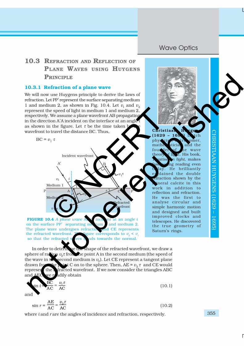
We will now use Huygens principle to derive the laws ofrefraction. Let PP′ represent the surface separating medium1 and medium 2, as shown in Fig. 10.4. Let v1 and v2
represent the speed of light in medium 1 and medium 2,respectively. We assume a plane wavefront AB propagatingin the direction A′A incident on the interface at an angle ias shown in the figure. Let τ be the time taken by thewavefront to travel the distance BC. Thus,
BC = v1 τ
In order to determine the shape of the refracted wavefront, we draw asphere of radius v2τ from the point A in the second medium (the speed ofthe wave in the second medium is v2). Let CE represent a tangent planedrawn from the point C on to the sphere. Then, AE = v2 τ and CE wouldrepresent the refracted wavefront. If we now consider the triangles ABCand AEC, we readily obtain
sin i = 1BCAC AC
v τ= (10.1)
and
sin r = 2AEAC AC
v τ= (10.2)
where i and r are the angles of incidence and refraction, respectively.
FIGURE 10.4 A plane wave AB is incident at an angle i
on the surface PP′ separating medium 1 and medium 2.
The plane wave undergoes refraction and CE representsthe refracted wavefront. The figure corresponds to v2 < v1
so that the refracted waves bends towards the normal.
CH
RIS
TIA
AN
HU
YG
EN
S (1
629 – 1
695)
Christiaan Huygens
(1629 – 1695) Dutchphysicist, astronomer,mathematician and thefounder of the wavetheory of light. His book,Treatise on light, makesfascinating reading eventoday. He brilliantlyexplained the doublerefraction shown by themineral calcite in thiswork in addition toreflection and refraction.He was the first toanalyse circular andsimple harmonic motionand designed and builtimproved clocks andtelescopes. He discoveredthe true geometry ofSaturn’s rings.
© NCERT
not to
be re
publi
shed
Physics
356
Thus we obtain
1
2
sinsin
i v
r v= (10.3)
From the above equation, we get the important result that if r < i (i.e.,if the ray bends toward the normal), the speed of the light wave in thesecond medium (v
2) will be less then the speed of the light wave in the
first medium (v1). This prediction is opposite to the prediction from the
corpuscular model of light and as later experiments showed, the predictionof the wave theory is correct. Now, if c represents the speed of light invacuum, then,
11
cn
v= (10.4)
and
n2 = 2
c
v(10.5)
are known as the refractive indices of medium 1 and medium 2,respectively. In terms of the refractive indices, Eq. (10.3) can bewritten as
n1 sin i = n2 sin r (10.6)
This is the Snell’s law of refraction. Further, if λ1 and λ 2 denote thewavelengths of light in medium 1 and medium 2, respectively and if thedistance BC is equal to λ
1 then the distance AE will be equal to λ
2 (because
if the crest from B has reached C in time τ, then the crest from A shouldhave also reached E in time τ ); thus,
1 1
2 2
BCAE
v
v
λ
λ= =
or
1 2
1 2
v v
λ λ= (10.7)
The above equation implies that when a wave gets refracted into adenser medium (v1 > v2) the wavelength and the speed of propagationdecrease but the frequency ν (= v/λ) remains the same.
10.3.2 Refraction at a rarer medium
We now consider refraction of a plane wave at a rarer medium, i.e.,v
2 > v
1. Proceeding in an exactly similar manner we can construct a
refracted wavefront as shown in Fig. 10.5. The angle of refractionwill now be greater than angle of incidence; however, we will still haven1 sin i = n2 sin r . We define an angle ic by the following equation
2
1
sin c
ni
n= (10.8)
Thus, if i = ic then sin r = 1 and r = 90°. Obviously, for i > ic, there cannot be any refracted wave. The angle i
c is known as the critical angle and
for all angles of incidence greater than the critical angle, we will not have
Dem
on
str
ati
on
o
f in
terf
ere
nce,
dif
fracti
on
, re
fracti
on
, re
so
nan
ce an
d D
op
ple
r eff
ect
http://w
ww
.fal
stad
.com
/rip
ple
/ © NCERT
not to
be re
publi
shed
357
Wave Optics
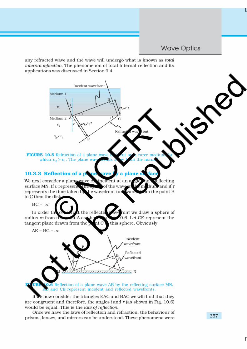
any refracted wave and the wave will undergo what is known as total
internal reflection. The phenomenon of total internal reflection and itsapplications was discussed in Section 9.4.
FIGURE 10.5 Refraction of a plane wave incident on a rarer medium forwhich v
2 > v
1. The plane wave bends away from the normal.
10.3.3 Reflection of a plane wave by a plane surface
We next consider a plane wave AB incident at an angle i on a reflectingsurface MN. If v represents the speed of the wave in the medium and if τrepresents the time taken by the wavefront to advance from the point Bto C then the distance
BC = vτ
In order the construct the reflected wavefront we draw a sphere ofradius vτ from the point A as shown in Fig. 10.6. Let CE represent thetangent plane drawn from the point C to this sphere. Obviously
AE = BC = vτ
FIGURE 10.6 Reflection of a plane wave AB by the reflecting surface MN.AB and CE represent incident and reflected wavefronts.
If we now consider the triangles EAC and BAC we will find that theyare congruent and therefore, the angles i and r (as shown in Fig. 10.6)would be equal. This is the law of reflection.
Once we have the laws of reflection and refraction, the behaviour ofprisms, lenses, and mirrors can be understood. These phenomena were
© NCERT
not to
be re
publi
shed
Physics
358
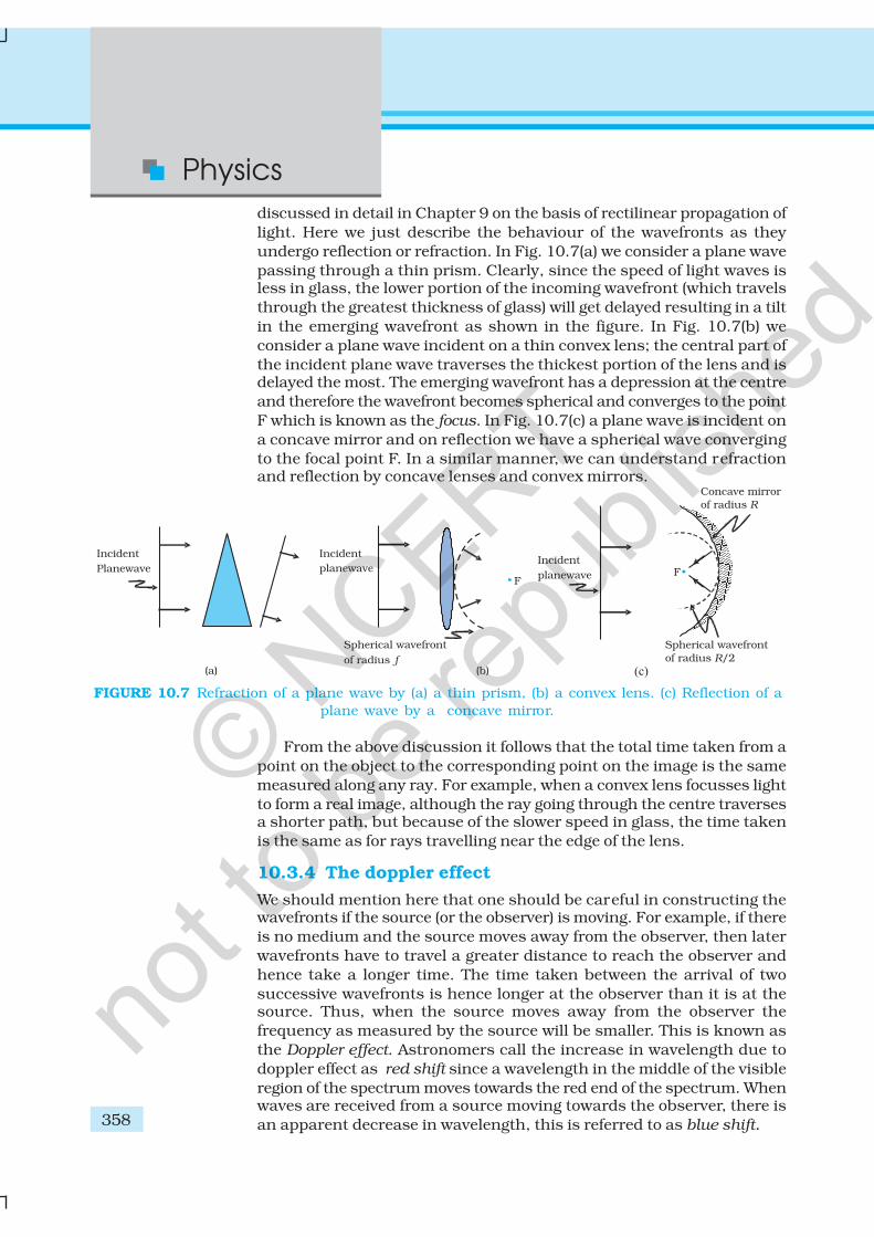
discussed in detail in Chapter 9 on the basis of rectilinear propagation oflight. Here we just describe the behaviour of the wavefronts as theyundergo reflection or refraction. In Fig. 10.7(a) we consider a plane wavepassing through a thin prism. Clearly, since the speed of light waves isless in glass, the lower portion of the incoming wavefront (which travelsthrough the greatest thickness of glass) will get delayed resulting in a tiltin the emerging wavefront as shown in the figure. In Fig. 10.7(b) weconsider a plane wave incident on a thin convex lens; the central part ofthe incident plane wave traverses the thickest portion of the lens and isdelayed the most. The emerging wavefront has a depression at the centreand therefore the wavefront becomes spherical and converges to the pointF which is known as the focus. In Fig. 10.7(c) a plane wave is incident ona concave mirror and on reflection we have a spherical wave convergingto the focal point F. In a similar manner, we can understand refractionand reflection by concave lenses and convex mirrors.
FIGURE 10.7 Refraction of a plane wave by (a) a thin prism, (b) a convex lens. (c) Reflection of aplane wave by a concave mirror.
From the above discussion it follows that the total time taken from apoint on the object to the corresponding point on the image is the samemeasured along any ray. For example, when a convex lens focusses lightto form a real image, although the ray going through the centre traversesa shorter path, but because of the slower speed in glass, the time takenis the same as for rays travelling near the edge of the lens.
10.3.4 The doppler effect
We should mention here that one should be careful in constructing thewavefronts if the source (or the observer) is moving. For example, if thereis no medium and the source moves away from the observer, then laterwavefronts have to travel a greater distance to reach the observer andhence take a longer time. The time taken between the arrival of twosuccessive wavefronts is hence longer at the observer than it is at thesource. Thus, when the source moves away from the observer thefrequency as measured by the source will be smaller. This is known asthe Doppler effect. Astronomers call the increase in wavelength due todoppler effect as red shift since a wavelength in the middle of the visibleregion of the spectrum moves towards the red end of the spectrum. Whenwaves are received from a source moving towards the observer, there isan apparent decrease in wavelength, this is referred to as blue shift.
© NCERT
not to
be re
publi
shed
359
Wave Optics
EX
AM
PLE 1
0.1
You have already encountered Doppler effect for sound waves inChapter 15 of Class XI textbook. For velocities small compared to thespeed of light, we can use the same formulae which we use for soundwaves. The fractional change in frequency ∆ν/ν is given by –vradial/c, wherev
radial is the component of the source velocity along the line joining the
observer to the source relative to the observer; vradial
is considered positivewhen the source moves away from the observer. Thus, the Doppler shiftcan be expressed as:
– radialv
c
ν
ν
∆= (10.9)
The formula given above is valid only when the speed of the source issmall compared to that of light. A more accurate formula for the Dopplereffect which is valid even when the speeds are close to that of light, requiresthe use of Einstein’s special theory of relativity. The Doppler effect forlight is very important in astronomy. It is the basis for the measurementsof the radial velocities of distant galaxies.
Example 10.1 What speed should a galaxy move with respectto us so that the sodium line at 589.0 nm is observedat 589.6 nm?
Solution Since νλ = c, –ν λ
ν λ
∆ ∆= (for small changes in ν and λ). For
∆λ = 589.6 – 589.0 = + 0.6 nm
we get [using Eq. (10.9)]
– – radialv
c
ν λ
ν λ
∆ ∆= =
or, vradial
5 –10.63.06 10 ms
589.0c
≅ + = + ×
= 306 km/s
Therefore, the galaxy is moving away from us.
Example 10.2
(a) When monochromatic light is incident on a surface separatingtwo media, the reflected and refracted light both have the samefrequency as the incident frequency. Explain why?
(b) When light travels from a rarer to a denser medium, the speeddecreases. Does the reduction in speed imply a reduction in theenergy carried by the light wave?
(c) In the wave picture of light, intensity of light is determined by thesquare of the amplitude of the wave. What determines the intensityof light in the photon picture of light.
Solution(a) Reflection and refraction arise through interaction of incident light
with the atomic constituents of matter. Atoms may be viewed as
EX
AM
PLE 1
0.2
© NCERT
not to
be re
publi
shed
Physics
360
EX
AM
PLE 1
0.2
oscillators, which take up the frequency of the external agency (light)causing forced oscillations. The frequency of light emitted by a chargedoscillator equals its frequency of oscillation. Thus, the frequency ofscattered light equals the frequency of incident light.
(b) No. Energy carried by a wave depends on the amplitude of thewave, not on the speed of wave propagation.
(c) For a given frequency, intensity of light in the photon picture isdetermined by the number of photons crossing an unit area perunit time.
10.4 COHERENT AND INCOHERENT ADDITION OF WAVES
In this section we will discuss the interference pattern produced bythe superposition of two waves. You may recall that we had discussedthe superposition principle in Chapter 15 of your Class XI textbook.Indeed the entire field of interference is based on the superposition
principle according to which at a particular point in the medium, the
resultant displacement produced by a number of waves is the vector
sum of the displacements produced by each of the waves.
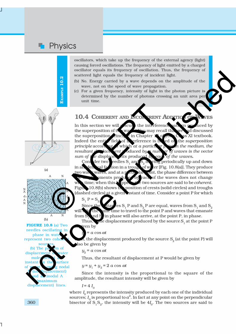
Consider two needles S1 and S
2 moving periodically up and down
in an identical fashion in a trough of water [Fig. 10.8(a)]. They producetwo water waves, and at a particular point, the phase difference betweenthe displacements produced by each of the waves does not changewith time; when this happens the two sources are said to be coherent.Figure 10.8(b) shows the position of crests (solid circles) and troughs(dashed circles) at a given instant of time. Consider a point P for which
S1 P = S
2 P
Since the distances S1 P and S
2 P are equal, waves from S
1 and S
2will take the same time to travel to the point P and waves that emanatefrom S
1 and S
2 in phase will also arrive, at the point P, in phase.
Thus, if the displacement produced by the source S1 at the point P
is given by
y1 = a cos ωt
then, the displacement produced by the source S2 (at the point P) will
also be given by
y2 = a cos ωt
Thus, the resultant of displacement at P would be given by
y = y1 + y
2 = 2 a cos ωt
Since the intensity is the proportional to the square of theamplitude, the resultant intensity will be given by
I = 4 I0
where I0 represents the intensity produced by each one of the individual
sources; I0 is proportional to a2. In fact at any point on the perpendicular
bisector of S1S
2, the intensity will be 4I
0. The two sources are said to
(a)
(b)
FIGURE 10.8 (a) Twoneedles oscillating in
phase in waterrepresent two coherent
sources.(b) The pattern of
displacement of watermolecules at an
instant on the surfaceof water showing nodal
N (no displacement)and antinodal A
(maximumdisplacement) lines.
© NCERT
not to
be re
publi
shed
361
Wave Optics
interfere constructively and we have what is referred to as constructive
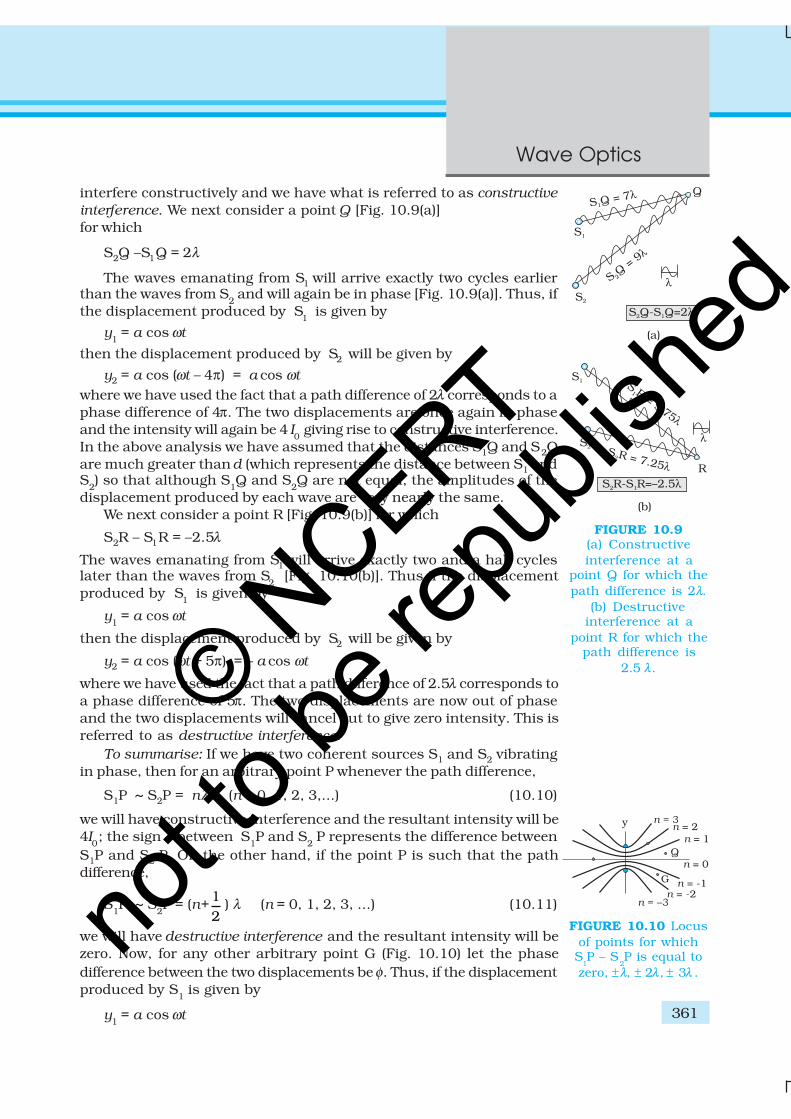
interference. We next consider a point Q [Fig. 10.9(a)]for which
S2Q –S1Q = 2λ
The waves emanating from S1 will arrive exactly two cycles earlierthan the waves from S
2 and will again be in phase [Fig. 10.9(a)]. Thus, if
the displacement produced by S1
is given by
y1 = a cos ωt
then the displacement produced by S2 will be given by
y2 = a cos (ωt – 4π) = a cos ωt
where we have used the fact that a path difference of 2λ corresponds to aphase difference of 4π. The two displacements are once again in phaseand the intensity will again be 4 I
0 giving rise to constructive interference.
In the above analysis we have assumed that the distances S1Q and S2Qare much greater than d (which represents the distance between S1 andS
2) so that although S
1Q and S
2Q are not equal, the amplitudes of the
displacement produced by each wave are very nearly the same.We next consider a point R [Fig. 10.9(b)] for which
S2R – S1R = –2.5λ
The waves emanating from S1 will arrive exactly two and a half cycleslater than the waves from S
2 [Fig. 10.10(b)]. Thus if the displacement
produced by S1
is given by
y1 = a cos ωt
then the displacement produced by S2 will be given by
y2 = a cos (ωt + 5π) = – a cos ωt
where we have used the fact that a path difference of 2.5λ corresponds toa phase difference of 5π. The two displacements are now out of phaseand the two displacements will cancel out to give zero intensity. This isreferred to as destructive interference.
To summarise: If we have two coherent sources S1 and S2 vibratingin phase, then for an arbitrary point P whenever the path difference,
S1P ~ S2P = nλ (n = 0, 1, 2, 3,...) (10.10)
we will have constructive interference and the resultant intensity will be4I
0; the sign ~ between S
1P and S
2 P represents the difference between
S1P and S2 P. On the other hand, if the point P is such that the pathdifference,
S1P ~ S
2P = (n+ 1
2) λ (n = 0, 1, 2, 3, ...) (10.11)
we will have destructive interference and the resultant intensity will bezero. Now, for any other arbitrary point G (Fig. 10.10) let the phasedifference between the two displacements be φ. Thus, if the displacementproduced by S
1 is given by
y1 = a cos ωt
FIGURE 10.9(a) Constructiveinterference at a
point Q for which thepath difference is 2λ.
(b) Destructiveinterference at a
point R for which thepath difference is
2.5 λ.
FIGURE 10.10 Locusof points for whichS
1P – S
2P is equal to
zero, ±λ, ± 2λ, ± 3λ .
© NCERT
not to
be re
publi
shed
Physics
362
then, the displacement produced by S2 would be
y2 = a cos (ωt + φ )
and the resultant displacement will be given by
y = y1 + y2
= a [cos ωt + cos (ωt +φ)]
= 2 a cos (φ/2) cos (ωt + φ/2)
The amplitude of the resultant displacement is 2a cos (φ/2) andtherefore the intensity at that point will be
I = 4 I0 cos2 (φ/2) (10.12)
If φ = 0, ± 2 π, ± 4 π,… which corresponds to the condition given byEq. (10.10) we will have constructive interference leading to maximumintensity. On the other hand, if φ = ± π, ± 3π, ± 5π … [which corresponds tothe condition given by Eq. (10.11)] we will have destructive interferenceleading to zero intensity.
Now if the two sources are coherent (i.e., if the two needles are goingup and down regularly) then the phase difference φ at any point will notchange with time and we will have a stable interference pattern; i.e., thepositions of maxima and minima will not change with time. However, ifthe two needles do not maintain a constant phase difference, then theinterference pattern will also change with time and, if the phase differencechanges very rapidly with time, the positions of maxima and minima willalso vary rapidly with time and we will see a “time-averaged” intensitydistribution. When this happens, we will observe an average intensitythat will be given by
( )2
04 cos /2I I φ< >= < > (10.13)
where angular brackets represent time averaging. Indeed it is shown inSection 7.2 that if φ(t ) varies randomly with time, the time-averagedquantity < cos2 (φ/2) > will be 1/2. This is also intuitively obvious becausethe function cos2 (φ/2) will randomly vary between 0 and 1 and theaverage value will be 1/2. The resultant intensity will be given by
I = 2 I0
(10.14)
at all points.When the phase difference between the two vibrating sources changes
rapidly with time, we say that the two sources are incoherent and whenthis happens the intensities just add up. This is indeed what happenswhen two separate light sources illuminate a wall.
10.5 INTERFERENCE OF LIGHT WAVES AND YOUNG’S
EXPERIMENT
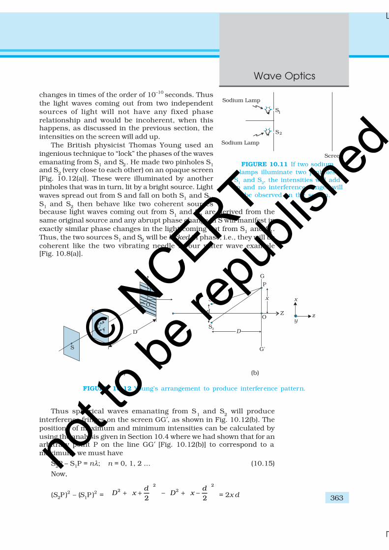
We will now discuss interference using light waves. If we use two sodiumlamps illuminating two pinholes (Fig. 10.11) we will not observe anyinterference fringes. This is because of the fact that the light wave emittedfrom an ordinary source (like a sodium lamp) undergoes abrupt phase
Rip
ple
Tan
k exp
eri
men
ts o
n w
ave in
terf
ere
nce
http://w
ww
.colo
rado.e
du/p
hys
ics/
2000/a
pple
ts/fourier
.htm
l
© NCERT
not to
be re
publi
shed
363
Wave Optics
changes in times of the order of 10–10 seconds. Thusthe light waves coming out from two independentsources of light will not have any fixed phaserelationship and would be incoherent, when thishappens, as discussed in the previous section, theintensities on the screen will add up.
The British physicist Thomas Young used aningenious technique to “lock” the phases of the wavesemanating from S1 and S2. He made two pinholes S1and S
2 (very close to each other) on an opaque screen
[Fig. 10.12(a)]. These were illuminated by anotherpinholes that was in turn, lit by a bright source. Lightwaves spread out from S and fall on both S1 and S2.S1 and S2 then behave like two coherent sourcesbecause light waves coming out from S
1 and S
2 are derived from the
same original source and any abrupt phase change in S will manifest inexactly similar phase changes in the light coming out from S1 and S2.Thus, the two sources S1 and S2 will be locked in phase; i.e., they will becoherent like the two vibrating needle in our water wave example[Fig. 10.8(a)].
FIGURE 10.11 If two sodiumlamps illuminate two pinholes
S1 and S2, the intensities will addup and no interference fringes will
be observed on the screen.
Thus spherical waves emanating from S1 and S
2 will produce
interference fringes on the screen GG′, as shown in Fig. 10.12(b). Thepositions of maximum and minimum intensities can be calculated byusing the analysis given in Section 10.4 where we had shown that for anarbitrary point P on the line GG′ [Fig. 10.12(b)] to correspond to amaximum, we must have
S2P – S1P = nλ; n = 0, 1, 2 ... (10.15)
Now,
(S2P )2 – (S1P )2 =
22 –
2d
D x
+ +
22 –
2d
D x
+
= 2x d
(a) (b)
FIGURE 10.12 Young’s arrangement to produce interference pattern.
© NCERT
not to
be re
publi
shed
Physics
364
where S1S
2 = d and OP = x . Thus
S2P – S
1P =
2 1
2S P+S P
xd(10.16)
If x, d<<D then negligible error will be introduced ifS2P + S1P (in the denominator) is replaced by 2D. Forexample, for d = 0.1 cm, D = 100 cm, OP = 1 cm (whichcorrespond to typical values for an interferenceexperiment using light waves), we have
S2P + S1P = [(100)2 + (1.05)2]½ + [(100)2 + (0.95)2]½
≈200.01 cmThus if we replace S
2P + S
1P by 2 D, the error involved is
about 0.005%. In this approximation, Eq. (10.16)becomes
S2P – S1P ≈ (10.17)
Hence we will have constructive interference resulting ina bright region when
x = xn =
n D
d
λ; n = 0, ± 1, ± 2, ... (10.18)
On the other hand, we will have a dark region near
x = xn = (n+ ) ; 0, 1, 2
Dn
d
λ= ± ± (10.19)
Thus dark and bright bands appear on the screen, as shown inFig. 10.13. Such bands are called fringes. Equations (10.18) and (10.19)show that dark and bright fringes are equally spaced and the distancebetween two consecutive bright and dark fringes is given by
β = xn+1
–xn
or β = D
d
λ(10.20)
which is the expression for the fringe width. Obviously, the central pointO (in Fig. 10.12) will be bright because S1O = S2O and it will correspondto n = 0. If we consider the line perpendicular to the plane of the paperand passing through O [i.e., along the y-axis] then all points on this linewill be equidistant from S1 and S2 and we will have a bright central fringewhich is a straight line as shown in Fig. 10.13. In order to determine theshape of the interference pattern on the screen we note that a particularfringe would correspond to the locus of points with a constant value ofS
2P – S
1P. Whenever this constant is an integral multiple of λ, the fringe
will be bright and whenever it is an odd integral multiple of λ/2 it will bea dark fringe. Now, the locus of the point P lying in the x-y plane suchthat S2P – S1P (= ∆) is a constant, is a hyperbola. Thus the fringe patternwill strictly be a hyperbola; however, if the distance D is very large comparedto the fringe width, the fringes will be very nearly straight lines as shownin Fig. 10.13.
Thomas Young
(1773 – 1829) Englishphysicist, physician andEgyptologist. Young workedon a wide variety ofscientific problems, rangingfrom the structure of the eyeand the mechanism ofvision to the deciphermentof the Rosetta stone. Herevived the wave theory oflight and recognised thatinterference phenomenaprovide proof of the waveproperties of light.
TH
OM
AS
YO
UN
G (1773 –
1829)
© NCERT
not to
be re
publi
shed
365
Wave Optics
In the double-slit experiment shown in Fig. 10.12, we have taken thesource hole S on the perpendicular bisector of the two slits, which isshown as the line SO. What happens if the source S is slightly away fromthe perpendicular bisector. Consider that the source is moved to somenew point S′ and suppose that Q is the mid-point of S1 and S2. If theangle S′QS is φ, then the central bright fringe occurs at an angle –φ, onthe other side. Thus, if the source S is on the perpendicular bisector,then the central fringe occurs at O, also on the perpendicular bisector. IfS is shifted by an angle φ to point S′, then the central fringe appears at apoint O′ at an angle –φ, which means that it is shifted by the same angleon the other side of the bisector. This also means that the source S ′, themid-point Q and the point O′ of the central fringe are in a straight line.
We end this section by quoting from the Nobel lecture of Dennis Gabor*
The wave nature of light was demonstrated convincingly for thefirst time in 1801 by Thomas Young by a wonderfully simpleexperiment. He let a ray of sunlight into a dark room, placed a
dark screen in front of it, pierced with two small pinholes, andbeyond this, at some distance, a white screen. He then saw twodarkish lines at both sides of a bright line, which gave himsufficient encouragement to repeat the experiment, this time withspirit flame as light source, with a little salt in it to produce the
bright yellow sodium light. This time he saw a number of darklines, regularly spaced; the first clear proof that light added tolight can produce darkness. This phenomenon is called
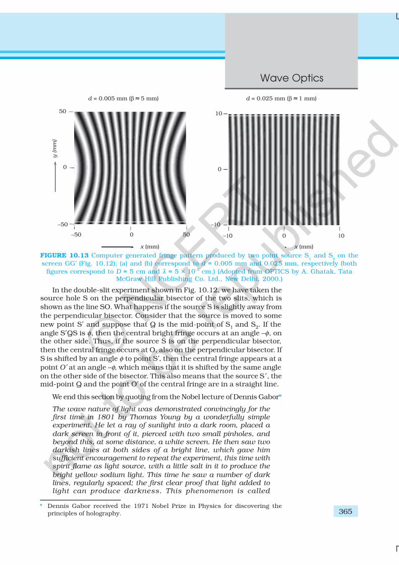
FIGURE 10.13 Computer generated fringe pattern produced by two point source S1 and S
2 on the
screen GG′ (Fig. 10.12); (a) and (b) correspond to d = 0.005 mm and 0.025 mm, respectively (bothfigures correspond to D = 5 cm and λ = 5 × 10⁻⁵ cm.) (Adopted from OPTICS by A. Ghatak, Tata
McGraw Hill Publishing Co. Ltd., New Delhi, 2000.)
* Dennis Gabor received the 1971 Nobel Prize in Physics for discovering theprinciples of holography.
© NCERT
not to
be re
publi
shed
Physics
366
EX
AM
PLE 1
0.3
interference. Thomas Young had expected it because he believedin the wave theory of light.
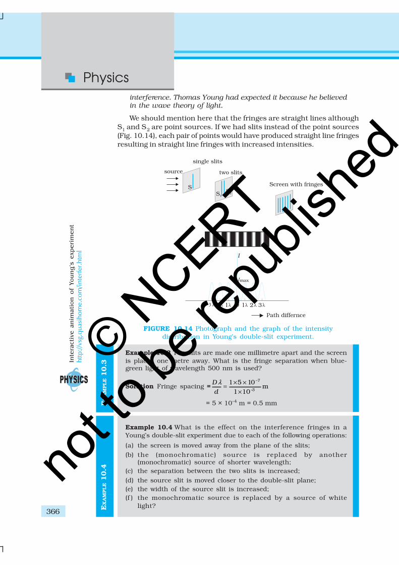
We should mention here that the fringes are straight lines althoughS1 and S2 are point sources. If we had slits instead of the point sources(Fig. 10.14), each pair of points would have produced straight line fringesresulting in straight line fringes with increased intensities.
Example 10.3 Two slits are made one millimetre apart and the screenis placed one metre away. What is the fringe separation when blue-green light of wavelength 500 nm is used?
Solution Fringe spacing =–7
–3
1 5 10m
1 10
D
d
λ × ×=
×
= 5 × 10⁻⁴ m = 0.5 mm
Example 10.4 What is the effect on the interference fringes in aYoung’s double-slit experiment due to each of the following operations:
(a) the screen is moved away from the plane of the slits;
(b) the (monochromatic) source is replaced by another(monochromatic) source of shorter wavelength;
(c) the separation between the two slits is increased;
(d) the source slit is moved closer to the double-slit plane;(e) the width of the source slit is increased;(f ) the monochromatic source is replaced by a source of white
light?
FIGURE 10.14 Photograph and the graph of the intensitydistribution in Young’s double-slit experiment.
EX
AM
PLE 1
0.4
Inte
racti
ve an
imati
on
o
f Yo
un
g’s
exp
eri
men
t
http://v
sg.q
uas
ihom
e.co
m/inte
rfer
.htm
l
© NCERT
not to
be re
publi
shed
367
Wave Optics
EX
AM
PLE 1
0.4
( In each operation, take all parameters, other than the one specified,to remain unchanged.)
Solution
(a) Angular separation of the fringes remains constant(= λ/d ). The actual separation of the fringes increases inproportion to the distance of the screen from the plane of thetwo slits.
(b) The separation of the fringes (and also angular separation)decreases. See, however, the condition mentioned in (d) below.
(c) The separation of the fringes (and also angular separation)decreases. See, however, the condition mentioned in (d) below.
(d) Let s be the size of the source and S its distance from the plane ofthe two slits. For interference fringes to be seen, the conditions/S < λ/d should be satisfied; otherwise, interference patternsproduced by different parts of the source overlap and no fringesare seen. Thus, as S decreases (i.e., the source slit is broughtcloser), the interference pattern gets less and less sharp, andwhen the source is brought too close for this condition to be valid,the fringes disappear. Till this happens, the fringe separationremains fixed.
(e) Same as in (d). As the source slit width increases, fringe patterngets less and less sharp. When the source slit is so wide that thecondition s/S ≤ λ/d is not satisfied, the interference patterndisappears.
(f ) The interference patterns due to different component colours ofwhite light overlap (incoherently). The central bright fringes fordifferent colours are at the same position. Therefore, the centralfringe is white. For a point P for which S
2P –S
1P = λ
b/2, where λ
b
(≈ 4000 Å) represents the wavelength for the blue colour, the bluecomponent will be absent and the fringe will appear red in colour.Slightly farther away where S2Q–S1Q = λ
b = λ
r/2 where λ
r (≈ 8000 Å)
is the wavelength for the red colour, the fringe will be predominantlyblue.
Thus, the fringe closest on either side of the central white fringeis red and the farthest will appear blue. After a few fringes, noclear fringe pattern is seen.
10.6 DIFFRACTION
If we look clearly at the shadow cast by an opaque object, close to theregion of geometrical shadow, there are alternate dark and bright regionsjust like in interference. This happens due to the phenomenon ofdiffraction. Diffraction is a general characteristic exhibited by all types ofwaves, be it sound waves, light waves, water waves or matter waves. Sincethe wavelength of light is much smaller than the dimensions of mostobstacles; we do not encounter diffraction effects of light in everydayobservations. However, the finite resolution of our eye or of optical
© NCERT
not to
be re
publi
shed
Physics
368
instruments such as telescopes or microscopes is limited due to thephenomenon of diffraction. Indeed the colours that you see when a CD isviewed is due to diffraction effects. We will now discuss the phenomenonof diffraction.
10.6.1 The single slit
In the discussion of Young’s experiment, we stated that a single narrowslit acts as a new source from which light spreads out. Even before Young,early experimenters – including Newton – had noticed that light spreadsout from narrow holes and slits. It seems to turn around corners andenter regions where we would expect a shadow. These effects, known asdiffraction, can only be properly understood using wave ideas. After all,you are hardly surprised to hear sound waves from someone talkingaround a corner !
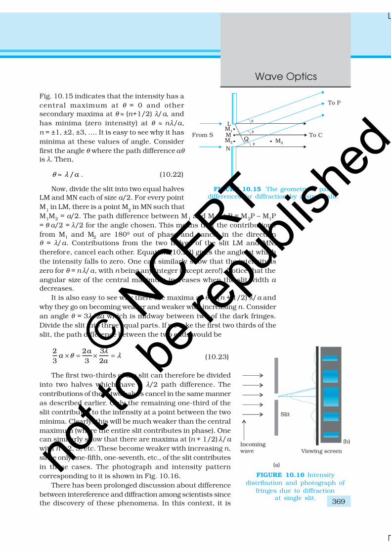
When the double slit in Young’s experiment is replaced by a singlenarrow slit (illuminated by a monochromatic source), a broad patternwith a central bright region is seen. On both sides, there are alternatedark and bright regions, the intensity becoming weaker away from thecentre (Fig. 10.16). To understand this, go to Fig. 10.15, which shows aparallel beam of light falling normally on a single slit LN of width a. Thediffracted light goes on to meet a screen. The midpoint of the slit is M.
A straight line through M perpendicular to the slit plane meets thescreen at C. We want the intensity at any point P on the screen. As before,straight lines joining P to the different points L,M,N, etc., can be treated asparallel, making an angle θ with the normal MC.
The basic idea is to divide the slit into much smaller parts, and addtheir contributions at P with the proper phase differences. We are treatingdifferent parts of the wavefront at the slit as secondary sources. Becausethe incoming wavefront is parallel to the plane of the slit, these sourcesare in phase.
The path difference NP – LP between the two edges of the slit can becalculated exactly as for Young’s experiment. From Fig. 10.15,
NP – LP = NQ
= a sin θ
≈ aθ (10.21)
Similarly, if two points M1 and M2 in the slit plane are separated by y, thepath difference M2P – M1P ≈ yθ. We now have to sum up equal, coherentcontributions from a large number of sources, each with a different phase.This calculation was made by Fresnel using integral calculus, so we omitit here. The main features of the diffraction pattern can be understood bysimple arguments.
At the central point C on the screen, the angle θ is zero. All pathdifferences are zero and hence all the parts of the slit contribute in phase.This gives maximum intensity at C. Experimental observation shown in
© NCERT
not to
be re
publi
shed
369
Wave Optics
Fig. 10.15 indicates that the intensity has acentral maximum at θ = 0 and othersecondary maxima at θ l (n+1/2) λ/a, andhas minima (zero intensity) at θ l nλ/a,n = ±1, ±2, ±3, .... It is easy to see why it hasminima at these values of angle. Considerfirst the angle θ where the path difference aθ
is λ. Then,
/aθ λ≈ . (10.22)
Now, divide the slit into two equal halvesLM and MN each of size a/2. For every pointM
1 in LM, there is a point M
2 in MN such that
M1M2 = a/2. The path difference between M1 and M2 at P = M2P – M1P= θ a/2 = λ/2 for the angle chosen. This means that the contributionsfrom M1 and M2 are 180º out of phase and cancel in the directionθ = λ/a. Contributions from the two halves of the slit LM and MN,therefore, cancel each other. Equation (10.22) gives the angle at whichthe intensity falls to zero. One can similarly show that the intensity iszero for θ = n λ/a, with n being any integer (except zero!). Notice that theangular size of the central maximum increases when the slit width adecreases.
It is also easy to see why there are maxima at θ = (n + 1/2) λ/a andwhy they go on becoming weaker and weaker with increasing n. Consideran angle θ = 3λ/2a which is midway between two of the dark fringes.Divide the slit into three equal parts. If we take the first two thirds of theslit, the path difference between the two ends would be
2 2 33 3 2
aa
a
λθ λ× = × = (10.23)
The first two-thirds of the slit can therefore be dividedinto two halves which have a λ/2 path difference. Thecontributions of these two halves cancel in the same manneras described earlier. Only the remaining one-third of theslit contributes to the intensity at a point between the twominima. Clearly, this will be much weaker than the centralmaximum (where the entire slit contributes in phase). Onecan similarly show that there are maxima at (n + 1/2) λ/a
with n = 2, 3, etc. These become weaker with increasing n,since only one-fifth, one-seventh, etc., of the slit contributesin these cases. The photograph and intensity patterncorresponding to it is shown in Fig. 10.16.
There has been prolonged discussion about differencebetween intereference and diffraction among scientists sincethe discovery of these phenomena. In this context, it is
FIGURE 10.16 Intensitydistribution and photograph of
fringes due to diffractionat single slit.
FIGURE 10.15 The geometry of pathdifferences for diffraction by a single slit.
© NCERT
not to
be re
publi
shed
Physics
370
EX
AM
PLE 1
0.5
interesting to note what Richard Feynman* has said in his famousFeynman Lectures on Physics:
No one has ever been able to define the difference betweeninterference and diffraction satisfactorily. It is just a question
of usage, and there is no specific, important physical difference
between them. The best we can do is, roughly speaking, is to
say that when there are only a few sources, say two interfering
sources, then the result is usually called interference, but if thereis a large number of them, it seems that the word diffraction is
more often used.
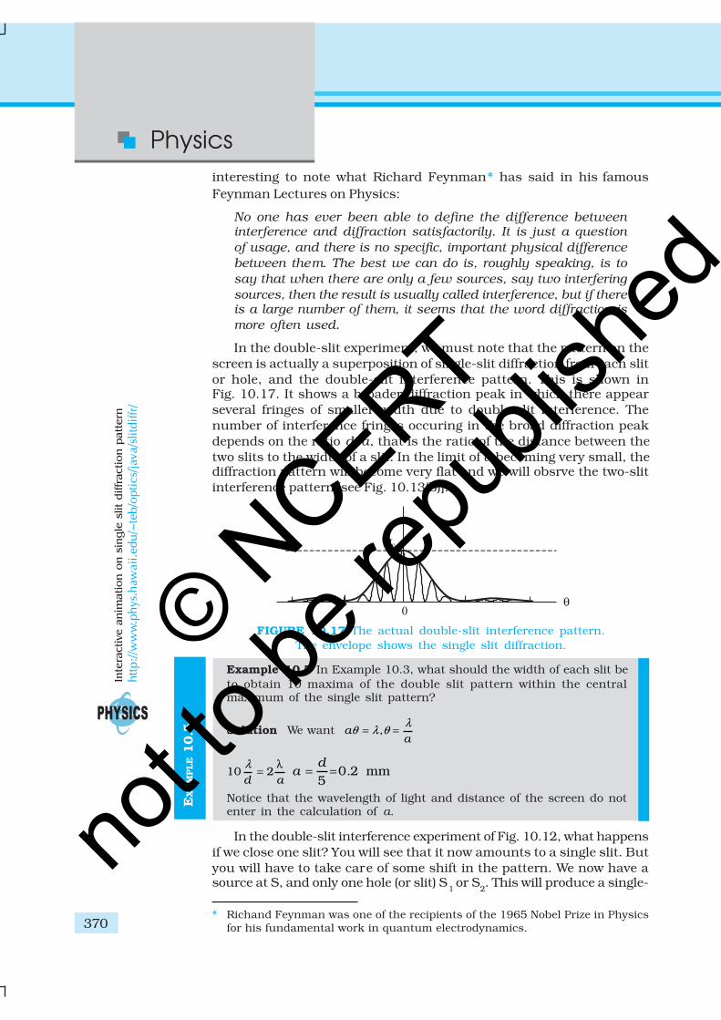
In the double-slit experiment, we must note that the pattern on thescreen is actually a superposition of single-slit diffraction from each slitor hole, and the double-slit interference pattern. This is shown inFig. 10.17. It shows a broader diffraction peak in which there appearseveral fringes of smaller width due to double-slit interference. Thenumber of interference fringes occuring in the broad diffraction peakdepends on the ratio d/a, that is the ratio of the distance between thetwo slits to the width of a slit. In the limit of a becoming very small, thediffraction pattern will become very flat and we will obsrve the two-slitinterference pattern [see Fig. 10.13(b)].
* Richand Feynman was one of the recipients of the 1965 Nobel Prize in Physicsfor his fundamental work in quantum electrodynamics.
Example 10.5 In Example 10.3, what should the width of each slit beto obtain 10 maxima of the double slit pattern within the centralmaximum of the single slit pattern?
Solution We want ,aa
λθ λ θ= =
10 2d a
λ λ= 0 2 mm
5d
a = = .
Notice that the wavelength of light and distance of the screen do notenter in the calculation of a.
In the double-slit interference experiment of Fig. 10.12, what happensif we close one slit? You will see that it now amounts to a single slit. Butyou will have to take care of some shift in the pattern. We now have asource at S, and only one hole (or slit) S
1 or S
2. This will produce a single-
FIGURE 10.17 The actual double-slit interference pattern.The envelope shows the single slit diffraction.
Inte
ractive a
nim
atio
n o
n s
ing
le s
lit
diffr
actio
n p
att
ern
http://w
ww
.phys
.haw
aii.ed
u/~
teb/o
ptics
/jav
a/sl
itdiffr/
© NCERT
not to
be re
publi
shed
371
Wave Optics
slit diffraction pattern on the screen. The centre of the central bright fringewill appear at a point which lies on the straight line SS
1 or SS
2, as the
case may be.We now compare and contrast the interference pattern with that seen
for a coherently illuminated single slit (usually called the single slitdiffraction pattern).(i) The interference pattern has a number of equally spaced bright and
dark bands. The diffraction pattern has a central bright maximumwhich is twice as wide as the other maxima. The intensity falls as wego to successive maxima away from the centre, on either side.
(ii) We calculate the interference pattern by superposing two wavesoriginating from the two narrow slits. The diffraction pattern is asuperposition of a continuous family of waves originating from eachpoint on a single slit.
(iii) For a single slit of width a, the first null of the interference patternoccurs at an angle of λ/a. At the same angle of λ/a, we get a maximum(not a null) for two narrow slits separated by a distance a.
One must understand that both d and a have to be quite small, to beable to observe good interference and diffraction patterns. For example,the separation d between the two slits must be of the order of a milimetreor so. The width a of each slit must be even smaller, of the order of 0.1 or0.2 mm.
In our discussion of Young’s experiment and the single-slit diffraction,we have assumed that the screen on which the fringes are formed is at alarge distance. The two or more paths from the slits to the screen weretreated as parallel. This situation also occurs when we place a converginglens after the slits and place the screen at the focus. Parallel paths fromthe slit are combined at a single point on the screen. Note that the lens
does not introduce any extra path differences in a parallel beam. Thisarrangement is often used since it gives more intensity than placing thescreen far away. If f is the focal length of the lens, then we can easily workout the size of the central bright maximum. In terms of angles, theseparation of the central maximum from the first null of the diffractionpattern is λ/a . Hence, the size on the screen will be f λ/a.
10.6.2 Seeing the single slit diffraction pattern
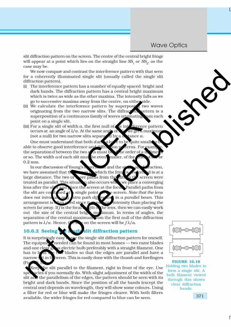
It is surprisingly easy to see the single-slit diffraction pattern for oneself.The equipment needed can be found in most homes –– two razor bladesand one clear glass electric bulb preferably with a straight filament. Onehas to hold the two blades so that the edges are parallel and have anarrow slit in between. This is easily done with the thumb and forefingers(Fig. 10.18).
Keep the slit parallel to the filament, right in front of the eye. Usespectacles if you normally do. With slight adjustment of the width of theslit and the parallelism of the edges, the pattern should be seen with itsbright and dark bands. Since the position of all the bands (except thecentral one) depends on wavelength, they will show some colours. Usinga filter for red or blue will make the fringes clearer. With both filtersavailable, the wider fringes for red compared to blue can be seen.
FIGURE 10.18Holding two blades toform a single slit. Abulb filament viewedthrough this shows
clear diffractionbands.
© NCERT
not to
be re
publi
shed

Physics
372
In this experiment, the filament plays the role of the first slit S inFig. 10.16. The lens of the eye focuses the pattern on the screen (theretina of the eye).
With some effort, one can cut a double slit in an aluminium foil witha blade. The bulb filament can be viewed as before to repeat Young’sexperiment. In daytime, there is another suitable bright source subtendinga small angle at the eye. This is the reflection of the Sun in any shinyconvex surface (e.g., a cycle bell). Do not try direct sunlight – it can damagethe eye and will not give fringes anyway as the Sun subtends an angleof (1/2)º.
In interference and diffraction, light energy is redistributed. If it
reduces in one region, producing a dark fringe, it increases in another
region, producing a bright fringe. There is no gain or loss of energy,
which is consistent with the principle of conservation of energy.
10.6.3 Resolving power of optical instruments
In Chapter 9 we had discussed about telescopes. The angular resolutionof the telescope is determined by the objective of the telescope. The starswhich are not resolved in the image produced by the objective cannot beresolved by any further magnification produced by the eyepiece. Theprimary purpose of the eyepiece is to provide magnification of the imageproduced by the objective.
Consider a parallel beam of light falling on a convex lens. If the lens iswell corrected for aberrations, then geometrical optics tells us that thebeam will get focused to a point. However, because of diffraction, thebeam instead of getting focused to a point gets focused to a spot of finitearea. In this case the effects due to diffraction can be taken into accountby considering a plane wave incident on a circular aperture followed bya convex lens (Fig. 10.19). The analysis of the corresponding diffractionpattern is quite involved; however, in principle, it is similar to the analysiscarried out to obtain the single-slit diffraction pattern. Taking into accountthe effects due to diffraction, the pattern on the focal plane would consistof a central bright region surrounded by concentric dark and bright rings(Fig. 10.19). A detailed analysis shows that the radius of the central brightregion is approximately given by
0
1.22 0.612
f fr
a a
λ λ≈ = (10.24)
FIGURE 10.19 A parallel beam of light is incident on a convex lens.Because of diffraction effects, the beam gets focused to a
spot of radius ≈ 0.61 λf/a .
© NCERT
not to
be re
publi
shed
373
Wave Optics
where f is the focal length of the lens and 2a is the diameter of the circularaperture or the diameter of the lens, whichever is smaller. Typically if
λ ≈ 0.5 µm, f ≈ 20 cm and a ≈ 5 cm
we have
r0 ≈ 1.2 µmAlthough the size of the spot is very small, it plays an important role
in determining the limit of resolution of optical instruments like a telescopeor a microscope. For the two stars to be just resolved
0
0.61 ff r
a
λθ∆ ≈ ≈
implying
0.61a
λθ∆ ≈ (10.25)
Thus ∆θ will be small if the diameter of the objective is large. Thisimplies that the telescope will have better resolving power if a is large. Itis for this reason that for better resolution, a telescope must have a largediameter objective.
Example 10.6 Assume that light of wavelength 6000Å is coming froma star. What is the limit of resolution of a telescope whose objectivehas a diameter of 100 inch?
Solution A 100 inch telescope implies that 2a = 100 inch= 254 cm. Thus if,
λ ≈ 6000Å = 6×10⁻⁵ cmthen
–5–70.61 6 10
2.9 10127
θ× ×
∆ ≈ ≈ × radians
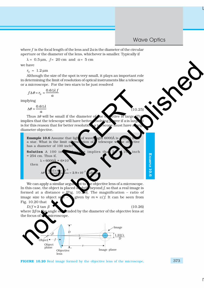
We can apply a similar argument to the objective lens of a microscope.In this case, the object is placed slightly beyond f, so that a real image isformed at a distance v [Fig. 10.20]. The magnification – ratio ofimage size to object size – is given by m l v/f. It can be seen fromFig. 10.20 that
D/f l 2 tan β (10.26)where 2β is the angle subtended by the diameter of the objective lens atthe focus of the microscope.
EX
AM
PLE 1
0.6
FIGURE 10.20 Real image formed by the objective lens of the microscope.
© NCERT
not to
be re
publi
shed
Physics
374
When the separation between two points in a microscopic specimenis comparable to the wavelength λ of the light, the diffraction effectsbecome important. The image of a point object will again be a diffractionpattern whose size in the image plane will be
1.22v v
D
λθ
=
(10.27)
Two objects whose images are closer than this distance will not beresolved, they will be seen as one. The corresponding minimumseparation, dmin, in the object plane is given by
dmin = 1 22
v mD
λ.
= 1 22
.v
D m
. λ
= 1 22 f
D
. λ(10.28)
Now, combining Eqs. (10.26) and (10.28), we get
min
1.222tan
dλ
β=
DETERMINE THE RESOLVING POWER OF YOUR EYE
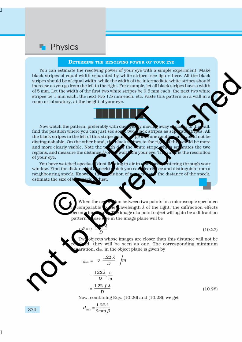
You can estimate the resolving power of your eye with a simple experiment. Makeblack stripes of equal width separated by white stripes; see figure here. All the blackstripes should be of equal width, while the width of the intermediate white stripes shouldincrease as you go from the left to the right. For example, let all black stripes have a widthof 5 mm. Let the width of the first two white stripes be 0.5 mm each, the next two whitestripes be 1 mm each, the next two 1.5 mm each, etc. Paste this pattern on a wall in aroom or laboratory, at the height of your eye.
Now watch the pattern, preferably with one eye. By moving away or closer to the wall,find the position where you can just see some two black stripes as separate stripes. Allthe black stripes to the left of this stripe would merge into one another and would not bedistinguishable. On the other hand, the black stripes to the right of this would be moreand more clearly visible. Note the width d of the white stripe which separates the tworegions, and measure the distance D of the wall from your eye. Then d/D is the resolutionof your eye.
You have watched specks of dust floating in air in a sunbeam entering through yourwindow. Find the distance (of a speck) which you can clearly see and distinguish from aneighbouring speck. Knowing the resolution of your eye and the distance of the speck,estimate the size of the speck of dust.
© NCERT
not to
be re
publi
shed
375
Wave Optics
1.222sin
λ
β� (10.29)
If the medium between the object and the objective lens is not air buta medium of refractive index n, Eq. (10.29) gets modified to
min
1.222 sin
dn
λ
β= (10.30)
The product n sinβ is called the numerical aperture and is sometimesmarked on the objective.
The resolving power of the microscope is given by the reciprocal ofthe minimum separation of two points seen as distinct. It can be seenfrom Eq. (10.30) that the resolving power can be increased by choosing amedium of higher refractive index. Usually an oil having a refractive indexclose to that of the objective glass is used. Such an arrangement is calledan ‘oil immersion objective’. Notice that it is not possible to make sinβ
larger than unity. Thus, we see that the resolving power of a microscopeis basically determined by the wavelength of the light used.
There is a likelihood of confusion between resolution andmagnification, and similarly between the role of a telescope and amicroscope to deal with these parameters. A telescope produces imagesof far objects nearer to our eye. Therefore objects which are not resolvedat far distance, can be resolved by looking at them through a telescope.A microscope, on the other hand, magnifies objects (which are near tous) and produces their larger image. We may be looking at two stars ortwo satellites of a far-away planet, or we may be looking at differentregions of a living cell. In this context, it is good to remember that atelescope resolves whereas a microscope magnifies.
10.6.4 The validity of ray optics
An aperture (i.e., slit or hole) of size a illuminated by a parallel beamsends diffracted light into an angle of approximately ≈ λ/a . This is theangular size of the bright central maximum. In travelling a distance z,the diffracted beam therefore acquires a width zλ/a due to diffraction. Itis interesting to ask at what value of z the spreading due to diffractionbecomes comparable to the size a of the aperture. We thus approximatelyequate zλ/a with a. This gives the distance beyond which divergence ofthe beam of width a becomes significant. Therefore,
2az
λ� (10.31)
We define a quantity zF
called the Fresnel distance by the followingequation
2 /Fz a λ�
Equation (10.31) shows that for distances much smaller than zF
, thespreading due to diffraction is smaller compared to the size of the beam.It becomes comparable when the distance is approximately zF . Fordistances much greater than zF, the spreading due to diffraction
© NCERT
not to
be re
publi
shed
Physics
376
EX
AM
PLE 1
0.7
dominates over that due to ray optics (i.e., the size a of the aperture).Equation (10.31) also shows that ray optics is valid in the limit ofwavelength tending to zero.
Example 10.7 For what distance is ray optics a good approximationwhen the aperture is 3 mm wide and the wavelength is 500 nm?
Solution ( )
2–32
–7
3 1018 m
5 10F
az
λ
×= = =
×
This example shows that even with a small aperture, diffractionspreading can be neglected for rays many metres in length. Thus, rayoptics is valid in many common situations.
10.7 POLARISATION
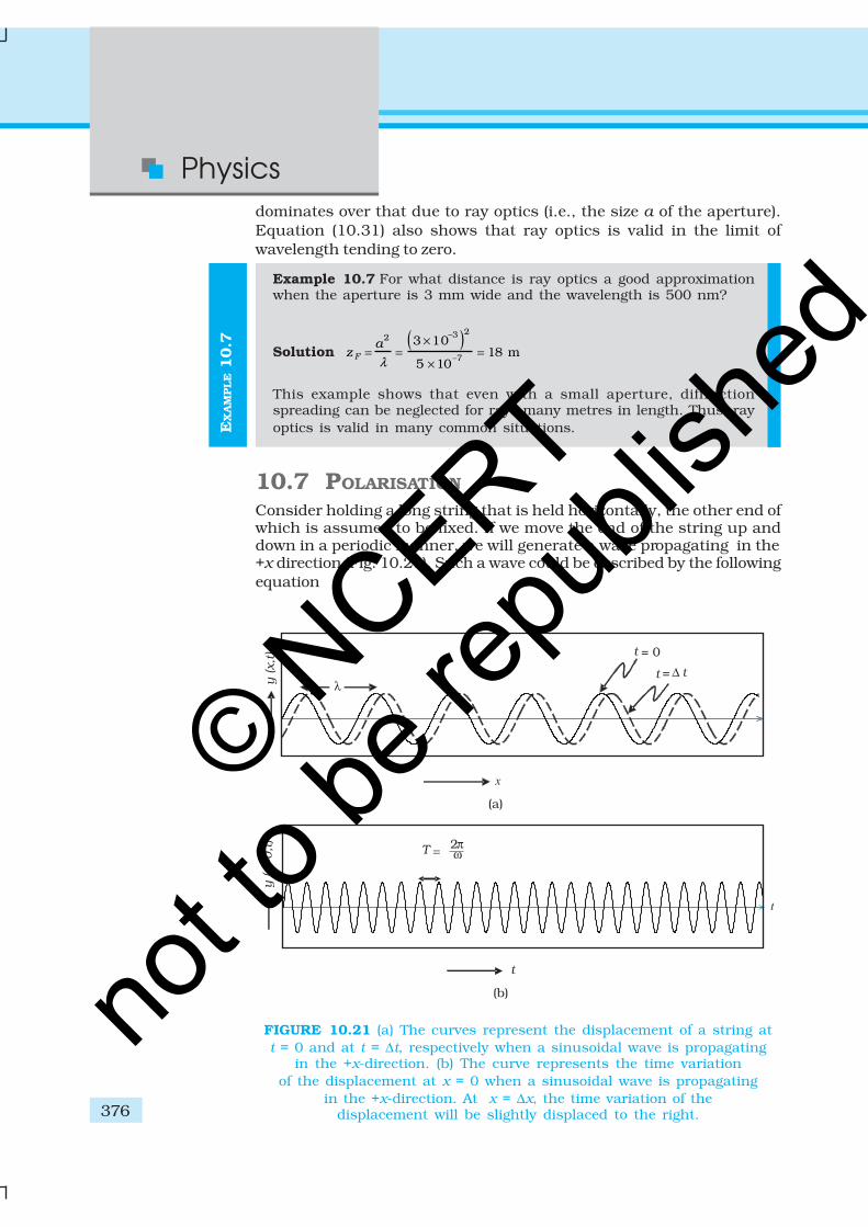
Consider holding a long string that is held horizontally, the other end ofwhich is assumed to be fixed. If we move the end of the string up anddown in a periodic manner, we will generate a wave propagating in the+x direction (Fig. 10.21). Such a wave could be described by the followingequation
FIGURE 10.21 (a) The curves represent the displacement of a string att = 0 and at t = ∆t, respectively when a sinusoidal wave is propagating
in the +x-direction. (b) The curve represents the time variationof the displacement at x = 0 when a sinusoidal wave is propagating
in the +x-direction. At x = ∆x, the time variation of thedisplacement will be slightly displaced to the right.
© NCERT
not to
be re
publi
shed
377
Wave Optics
y (x,t ) = a sin (kx – ωt) (10.32)
where a and ω (= 2πν ) represent the amplitude and the angular frequencyof the wave, respectively; further,
2k
λπ
= (10.33)
represents the wavelength associated with the wave. We had discussedpropagation of such waves in Chapter 15 of Class XI textbook. Since thedisplacement (which is along the y direction) is at right angles to thedirection of propagation of the wave, we have what is known as atransverse wave. Also, since the displacement is in the y direction, it isoften referred to as a y-polarised wave. Since each point on the stringmoves on a straight line, the wave is also referred to as a linearly polarisedwave. Further, the string always remains confined to the x-y plane andtherefore it is also referred to as a plane polarised wave.
In a similar manner we can consider the vibration of the string in thex-z plane generating a z-polarised wave whose displacement will be givenby
z (x,t ) = a sin (kx – ωt ) (10.34)
It should be mentioned that the linearly polarised waves [describedby Eqs. (10.33) and (10.34)] are all transverse waves; i.e., thedisplacement of each point of the string is always at right angles to thedirection of propagation of the wave. Finally, if the plane of vibration ofthe string is changed randomly in very short intervals of time, then wehave what is known as an unpolarised wave. Thus, for an unpolarisedwave the displacement will be randomly changing with time though itwill always be perpendicular to the direction of propagation.
Light waves are transverse in nature; i.e., the electric field associatedwith a propagating light wave is always at right angles to the direction ofpropagation of the wave. This can be easily demonstrated using a simplepolaroid. You must have seen thin plastic like sheets, which are calledpolaroids. A polaroid consists of long chain molecules aligned in aparticular direction. The electric vectors (associated with the propagatinglight wave) along the direction of the aligned molecules get absorbed.Thus, if an unpolarised light wave is incident on such a polaroid thenthe light wave will get linearly polarised with the electric vector oscillatingalong a direction perpendicular to the aligned molecules; this directionis known as the pass-axis of the polaroid.
Thus, if the light from an ordinary source (like a sodium lamp) passesthrough a polaroid sheet P
1, it is observed that its intensity is reduced by
half. Rotating P1 has no effect on the transmitted beam and transmittedintensity remains constant. Now, let an identical piece of polaroid P2 beplaced before P
1. As expected, the light from the lamp is reduced in
intensity on passing through P2 alone. But now rotating P1 has a dramaticeffect on the light coming from P
2. In one position, the intensity transmitted
© NCERT
not to
be re
publi
shed
Physics
378 EX
AM
PLE 1
0.8
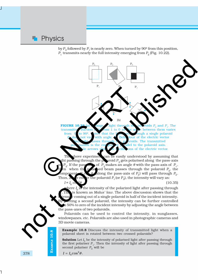
by P2 followed by P1 is nearly zero. When turned by 90º from this position,P
1 transmits nearly the full intensity emerging from P
2 (Fig. 10.22).
The above experiment can be easily understood by assuming thatlight passing through the polaroid P
2 gets polarised along the pass-axis
of P2. If the pass-axis of P
2 makes an angle θ with the pass-axis of P
1,
then when the polarised beam passes through the polaroid P2, the
component E cos θ (along the pass-axis of P2) will pass through P2.Thus, as we rotate the polaroid P1 (or P2), the intensity will vary as:
I = I0 cos2θ (10.35)
where I0 is the intensity of the polarized light after passing through
P1. This is known as Malus’ law. The above discussion shows that the
intensity coming out of a single polaroid is half of the incident intensity.By putting a second polaroid, the intensity can be further controlledfrom 50% to zero of the incident intensity by adjusting the angle betweenthe pass-axes of two polaroids.
Polaroids can be used to control the intensity, in sunglasses,windowpanes, etc. Polaroids are also used in photographic cameras and3D movie cameras.
Example 10.8 Discuss the intensity of transmitted light when apolaroid sheet is rotated between two crossed polaroids?
Solution Let I0 be the intensity of polarised light after passing throughthe first polariser P
1. Then the intensity of light after passing through
second polariser P2 will be2
0cosI I θ= ,
FIGURE 10.22 (a) Passage of light through two polaroids P2 and P1. Thetransmitted fraction falls from 1 to 0 as the angle between them varies
from 0º to 90º. Notice that the light seen through a single polaroidP1 does not vary with angle. (b) Behaviour of the electric vector
when light passes through two polaroids. The transmittedpolarisation is the component parallel to the polaroid axis.
The double arrows show the oscillations of the electric vector.
© NCERT
not to
be re
publi
shed
379
Wave Optics
where θ is the angle between pass axes of P1 and P
2. Since P
1 and P
3are crossed the angle between the pass axes of P2 and P3 will be(π/2–θ ). Hence the intensity of light emerging from P3 will be
2 20cos cos –
2I I θ θ
π =
= I0 cos2θ sin2
θ =(I0/4) sin22θ
Therefore, the transmitted intensity will be maximum when θ = π/4.
10.7.1 Polarisation by scattering
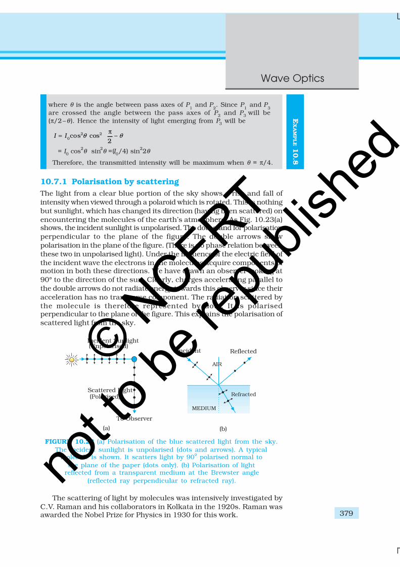
The light from a clear blue portion of the sky shows a rise and fall ofintensity when viewed through a polaroid which is rotated. This is nothingbut sunlight, which has changed its direction (having been scattered) onencountering the molecules of the earth’s atmosphere. As Fig. 10.23(a)shows, the incident sunlight is unpolarised. The dots stand for polarisationperpendicular to the plane of the figure. The double arrows showpolarisation in the plane of the figure. (There is no phase relation betweenthese two in unpolarised light). Under the influence of the electric field ofthe incident wave the electrons in the molecules acquire components ofmotion in both these directions. We have drawn an observer looking at90° to the direction of the sun. Clearly, charges accelerating parallel tothe double arrows do not radiate energy towards this observer since theiracceleration has no transverse component. The radiation scattered bythe molecule is therefore represented by dots. It is polarisedperpendicular to the plane of the figure. This explains the polarisation ofscattered light from the sky.
FIGURE 10.23 (a) Polarisation of the blue scattered light from the sky.The incident sunlight is unpolarised (dots and arrows). A typical
molecule is shown. It scatters light by 90º polarised normal tothe plane of the paper (dots only). (b) Polarisation of light
reflected from a transparent medium at the Brewster angle(reflected ray perpendicular to refracted ray).
The scattering of light by molecules was intensively investigated byC.V. Raman and his collaborators in Kolkata in the 1920s. Raman wasawarded the Nobel Prize for Physics in 1930 for this work.
EX
AM
PLE 1
0.8
© NCERT
not to
be re
publi
shed
Physics
380
A SPECIAL CASE OF TOTAL TRANSMISSION
When light is incident on an interface of two media, it is observed that some part of itgets reflected and some part gets transmitted. Consider a related question: Is it possible
that under some conditions a monochromatic beam of light incident on a surface(which is normally reflective) gets completely transmitted with no reflection? To yoursurprise, the answer is yes.
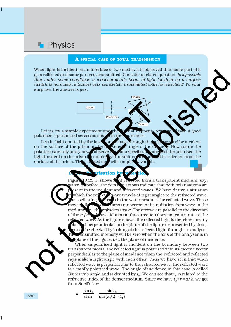
Let us try a simple experiment and check what happens. Arrange a laser, a goodpolariser, a prism and screen as shown in the figure here.
Let the light emitted by the laser source pass through the polariser and be incidenton the surface of the prism at the Brewster’s angle of incidence i
B. Now rotate the
polariser carefully and you will observe that for a specific alignment of the polariser, thelight incident on the prism is completely transmitted and no light is reflected from thesurface of the prism. The reflected spot will completely vanish.
10.7.2 Polarisation by reflection
Figure 10.23(b) shows light reflected from a transparent medium, say,water. As before, the dots and arrows indicate that both polarisations arepresent in the incident and refracted waves. We have drawn a situationin which the reflected wave travels at right angles to the refracted wave.The oscillating electrons in the water produce the reflected wave. Thesemove in the two directions transverse to the radiation from wave in themedium, i.e., the refracted wave. The arrows are parallel to the directionof the reflected wave. Motion in this direction does not contribute to thereflected wave. As the figure shows, the reflected light is therefore linearlypolarised perpendicular to the plane of the figure (represented by dots).This can be checked by looking at the reflected light through an analyser.The transmitted intensity will be zero when the axis of the analyser is inthe plane of the figure, i.e., the plane of incidence.
When unpolarised light is incident on the boundary between twotransparent media, the reflected light is polarised with its electric vectorperpendicular to the plane of incidence when the refracted and reflectedrays make a right angle with each other. Thus we have seen that whenreflected wave is perpendicular to the refracted wave, the reflected waveis a totally polarised wave. The angle of incidence in this case is calledBrewster’s angle and is denoted by iB. We can see that iB is related to therefractive index of the denser medium. Since we have iB+r = π/2, we getfrom Snell’s law
( )sin sinsin sin /2 –
B B
B
i i
r iµ = =
π
© NCERT
not to
be re
publi
shed
381
Wave Optics
EX
AM
PLE 1
0.9
sintan
cosB
B
B
ii
i= = (10.36)
This is known as Brewster’s law.
Example 10.9 Unpolarised light is incident on a plane glass surface.What should be the angle of incidence so that the reflected andrefracted rays are perpendicular to each other?
Solution For i + r to be equal to π/2, we should have tan iB = µ = 1.5.
This gives iB = 57°. This is the Brewster’s angle for air to glassinterface.
For simplicity, we have discussed scattering of light by 90º, andreflection at the Brewster angle. In this special situation, one of the twoperpendicular components of the electric field is zero. At other angles,both components are present but one is stronger than the other. There isno stable phase relationship between the two perpendicular componentssince these are derived from two perpendicular components of anunpolarised beam. When such light is viewed through a rotating analyser,one sees a maximum and a minimum of intensity but not completedarkness. This kind of light is called partially polarised.
Let us try to understand the situation. When an unpolarised beam oflight is incident at the Brewster’s angle on an interface of two media, onlypart of light with electric field vector perpendicular to the plane ofincidence will be reflected. Now by using a good polariser, if we completelyremove all the light with its electric vector perpendicular to the plane ofincidence and let this light be incident on the surface of the prism atBrewster’s angle, you will then observe no reflection and there will betotal transmission of light.
We began this chapter by pointing out that there are some phenomenawhich can be explained only by the wave theory. In order to develop aproper understanding, we first described how some phenomena likereflection and refraction, which were studied on this basis of Ray Opticsin Chapter 9, can also be understood on the basis of Wave Optics. Thenwe described Young’s double slit experiment which was a turning pointin the study of optics. Finally, we described some associated points suchas diffraction, resolution, polarisation, and validity of ray optics. In thenext chapter, you will see how new experiments led to new theories atthe turn of the century around 1900 A.D.
SUMMARY
1. Huygens’ principle tells us that each point on a wavefront is a sourceof secondary waves, which add up to give the wavefront at a later time.
2. Huygens’ construction tells us that the new wavefront is the forwardenvelope of the secondary waves. When the speed of light isindependent of direction, the secondary waves are spherical. The raysare then perpendicular to both the wavefronts and the time of travel
© NCERT
not to
be re
publi
shed

Physics
382
is the same measured along any ray. This principle leads to the wellknown laws of reflection and refraction.
3. The principle of superposition of waves applies whenever two or moresources of light illuminate the same point. When we consider theintensity of light due to these sources at the given point, there is aninterference term in addition to the sum of the individual intensities.But this term is important only if it has a non-zero average, whichoccurs only if the sources have the same frequency and a stablephase difference.
4. Young’s double slit of separation d gives equally spaced fringes ofangular separation λ/d. The source, mid-point of the slits, and centralbright fringe lie in a straight line. An extended source will destroythe fringes if it subtends angle more than λ/d at the slits.
5. A single slit of width a gives a diffraction pattern with a central
maximum. The intensity falls to zero at angles of 2
, ,a a
λ λ± ± etc.,
with successively weaker secondary maxima in between. Diffractionlimits the angular resolution of a telescope to λ/D where D is thediameter. Two stars closer than this give strongly overlapping images.Similarly, a microscope objective subtending angle 2β at the focus,in a medium of refractive index n, will just separate two objects spacedat a distance λ/(2n sin β), which is the resolution limit of amicroscope. Diffraction determines the limitations of the concept oflight rays. A beam of width a travels a distance a2/λ, called the Fresneldistance, before it starts to spread out due to diffraction.
6. Natural light, e.g., from the sun is unpolarised. This means the electricvector takes all possible directions in the transverse plane, rapidlyand randomly, during a measurement. A polaroid transmits only onecomponent (parallel to a special axis). The resulting light is calledlinearly polarised or plane polarised. When this kind of light is viewedthrough a second polaroid whose axis turns through 2π, two maximaand minima of intensity are seen. Polarised light can also be producedby reflection at a special angle (called the Brewster angle) and byscattering through π/2 in the earth’s atmosphere.
POINTS TO PONDER
1. Waves from a point source spread out in all directions, while light wasseen to travel along narrow rays. It required the insight and experimentof Huygens, Young and Fresnel to understand how a wave theory couldexplain all aspects of the behaviour of light.
2. The crucial new feature of waves is interference of amplitudes from differentsources which can be both constructive and destructive, as shown inYoung’s experiment.
3. Even a wave falling on single slit should be regarded as a large number ofsources which interefere constructively in the forward direction (θ = 0),and destructively in other directions.
4. Diffraction phenomena define the limits of ray optics. The limit of theability of microscopes and telescopes to distinguish very close objects isset by the wavelength of light.
5. Most interference and diffraction effects exist even for longitudinal waveslike sound in air. But polarisation phenomena are special to transversewaves like light waves.
© NCERT
not to
be re
publi
shed
383
Wave Optics
EXERCISES
10.1 Monochromatic light of wavelength 589 nm is incident from air on awater surface. What are the wavelength, frequency and speed of(a) reflected, and (b) refracted light? Refractive index of water is1.33.
10.2 What is the shape of the wavefront in each of the following cases:
(a) Light diverging from a point source.
(b) Light emerging out of a convex lens when a point source is placedat its focus.
(c) The portion of the wavefront of light from a distant star interceptedby the Earth.
10.3 (a) The refractive index of glass is 1.5. What is the speed of light inglass? (Speed of light in vacuum is 3.0 × 10⁸ m s–1)
(b) Is the speed of light in glass independent of the colour of light? Ifnot, which of the two colours red and violet travels slower in aglass prism?
10.4 In a Young’s double-slit experiment, the slits are separated by0.28 mm and the screen is placed 1.4 m away. The distance betweenthe central bright fringe and the fourth bright fringe is measuredto be 1.2 cm. Determine the wavelength of light used in theexperiment.
10.5 In Young’s double-slit experiment using monochromatic light ofwavelength λ, the intensity of light at a point on the screen wherepath difference is λ, is K units. What is the intensity of light at apoint where path difference is λ/3?
10.6 A beam of light consisting of two wavelengths, 650 nm and 520 nm,is used to obtain interference fringes in a Young’s double-slitexperiment.
(a) Find the distance of the third bright fringe on the screen fromthe central maximum for wavelength 650 nm.
(b) What is the least distance from the central maximum where thebright fringes due to both the wavelengths coincide?
10.7 In a double-slit experiment the angular width of a fringe is found tobe 0.2° on a screen placed 1 m away. The wavelength of light used is600 nm. What will be the angular width of the fringe if the entireexperimental apparatus is immersed in water? Take refractive indexof water to be 4/3.
10.8 What is the Brewster angle for air to glass transition? (Refractiveindex of glass = 1.5.)
10.9 Light of wavelength 5000 Å falls on a plane reflecting surface. Whatare the wavelength and frequency of the reflected light? For whatangle of incidence is the reflected ray normal to the incident ray?
10.10 Estimate the distance for which ray optics is good approximationfor an aperture of 4 mm and wavelength 400 nm.
© NCERT
not to
be re
publi
shed

Physics
384
ADDITIONAL EXERCISES
10.11 The 6563 Å Hα line emitted by hydrogen in a star is found to be red-shifted by 15 Å. Estimate the speed with which the star is recedingfrom the Earth.
10.12 Explain how Corpuscular theory predicts the speed of light in amedium, say, water, to be greater than the speed of light in vacuum.Is the prediction confirmed by experimental determination of thespeed of light in water? If not, which alternative picture of light isconsistent with experiment?
10.13 You have learnt in the text how Huygens’ principle leads to the lawsof reflection and refraction. Use the same principle to deduce directlythat a point object placed in front of a plane mirror produces avirtual image whose distance from the mirror is equal to the objectdistance from the mirror.
10.14 Let us list some of the factors, which could possibly influence thespeed of wave propagation:
(i) nature of the source.
(ii) direction of propagation.
(iii) motion of the source and/or observer.
(iv) wavelength.
(v) intensity of the wave.
On which of these factors, if any, does
(a) the speed of light in vacuum,
(b) the speed of light in a medium (say, glass or water),
depend?
10.15 For sound waves, the Doppler formula for frequency shift differsslightly between the two situations: (i) source at rest; observermoving, and (ii) source moving; observer at rest. The exact Dopplerformulas for the case of light waves in vacuum are, however, strictlyidentical for these situations. Explain why this should be so. Wouldyou expect the formulas to be strictly identical for the two situationsin case of light travelling in a medium?
10.16 In double-slit experiment using light of wavelength 600 nm, theangular width of a fringe formed on a distant screen is 0.1º. What isthe spacing between the two slits?
10.17 Answer the following questions:
(a) In a single slit diffraction experiment, the width of the slit ismade double the original width. How does this affect the sizeand intensity of the central diffraction band?
(b) In what way is diffraction from each slit related to theinterference pattern in a double-slit experiment?
(c) When a tiny circular obstacle is placed in the path of light froma distant source, a bright spot is seen at the centre of the shadowof the obstacle. Explain why?
(d) Two students are separated by a 7 m partition wall in a room10 m high. If both light and sound waves can bend around
© NCERT
not to
be re
publi
shed
385
Wave Optics
obstacles, how is it that the students are unable to see eachother even though they can converse easily.
(e) Ray optics is based on the assumption that light travels in astraight line. Diffraction effects (observed when light propagatesthrough small apertures/slits or around small obstacles)disprove this assumption. Yet the ray optics assumption is socommonly used in understanding location and several otherproperties of images in optical instruments. What is thejustification?
10.18 Two towers on top of two hills are 40 km apart. The line joiningthem passes 50 m above a hill halfway between the towers. What isthe longest wavelength of radio waves, which can be sent betweenthe towers without appreciable diffraction effects?
10.19 A parallel beam of light of wavelength 500 nm falls on a narrow slitand the resulting diffraction pattern is observed on a screen 1 maway. It is observed that the first minimum is at a distance of 2.5mm from the centre of the screen. Find the width of the slit.
10.20 Answer the following questions:
(a) When a low flying aircraft passes overhead, we sometimes noticea slight shaking of the picture on our TV screen. Suggest apossible explanation.
(b) As you have learnt in the text, the principle of linearsuperposition of wave displacement is basic to understandingintensity distributions in diffraction and interference patterns.What is the justification of this principle?
10.21 In deriving the single slit diffraction pattern, it was stated that theintensity is zero at angles of nλ/a. Justify this by suitably dividingthe slit to bring out the cancellation.
© NCERT
not to
be re
publi
shed