user's manual template€¦ · web viewprogram generator. for . simulation to ate. and . ate...
TRANSCRIPT

Velocity CAE Program Generator
For Simulation to ATE and ATE to ATE Conversion
Release 5.3

Configuration Guide

Velocity CAE Program GeneratorConfiguration Guide
COPYRIGHT NOTICE
Copyright 2008 Alliance ATE Consulting Group, Inc.
All rights reserved
Documentation version 2.0
Any technical documentation that is made available by Alliance ATE Consulting Group is the copyrighted work of Alliance ATE Consulting Group and is owned by Alliance ATE Consulting Group.
NO WARRANTY. The technical documentation is being delivered to you AS-IS and Alliance ATE Consulting Group makes no warranty as to its accuracy or use. Any use of the technical documentation or the information contained therein is at the risk of the user. Documentation may contain technical or other inaccuracies or typographical errors. Alliance ATE Consulting Group, Inc. reserves the right to make change without prior notice.
No part of this publication may be copied without the express written permission of Alliance ATE Consulting Group, 3080 Olcott St Suite 110C, Santa Clara, CA 95054.
TRADEMARKSVelocity CAE Program Generator, D10Shell, and ShellConstructor are trademarks of Alliance ATE Consulting Group.
Diamond, D10, and ITE are trademarks of Credence Systems Corporation.
Configuration Guide Page iii

TYPOGRAPHIC CONVENTIONS
This document uses specific typographic conventions in defining the syntax of all Velocity Configuration File elements. The following is a list of those conventions for each major syntactic category.
Bold Reserved words, such as keywords, plus any other symbols that are to be typed exactly as shown.
Italicized Placeholder for a user-specified symbol; or, placeholder for a high-level syntactical element – made up of smaller elements – that will be subsequently defined.
[ ] Regular style (not bold or italic) square brackets are used to enclose optional elements. For elements in which square brackets are part of the syntax, the brackets will be in bold font.
{ } Regular style (not bold or italic) braces (or, “curly brackets”) are used to enclose elements that are to be repeated 0 or more times. For elements in which braces are part of the syntax, the braces will be in bold font.
| The vertical bar is used to separate alternative choices for an element.
::= Two regular style colons and an equals sign means “can be replaced by”. This is used for breaking down a high-level syntactical element into its constituent elements.
The following is an example of a syntax definition using the typographic conventions listed above:
PINS pinList startStopList [ condition ] [ map ]
where,
pinList ::= pinName|groupName{,pinName|groupName}
startStopList ::= startAddr-stopAddr{,startAddr-stopAddr}
condition ::= COND = {conditionList}
where,
conditionList ::= refPin[[relativeCycle]]=“pinState”{
,refPin[[relativeCycle]]=“pinState”}
Configuration Guide Page iv

map ::= MAP = { [ originalStateList ]:targetState }
where,
originalStateList ::= one or more single logic-state characters
OBSERVATIONS:
1. In the PINS definition:
a. The symbols pinList, startStopList, condition, and map are high-level syntactical elements that are subsequently broken down into smaller elements.
b. The use of regular style square brackets around condition and map means that they are optional.
2. In the pinList definition (pinList ::=):
a. The symbol pinList is defined as a comma-separated list of elements in which each element can be either a pinName or a groupName.
b. Note the use of the regular style vertical bar to indicate a choice of either pinName or groupName.
c. Note the use of the regular style braces to indicate 0 or more additional pinName or groupName elements, each preceded by a required comma.
d. The fact that the first occurrence of pinName|groupName is not enclosed in square brackets or braces means that at least one element must be specified. Any others are optional.
3. In the condition definition (condition ::=):
a. The use of bold style braces means that braces are to be typed as a required part of the syntax.
4. In the conditionList definition (conditionList ::=):
a. Note that the symbol relativeCycle is enclosed in two sets of square brackets.
b. The innermost brackets are in bold font, indicating that square brackets are to be typed as a required part of the syntax.
Configuration Guide Page v
c. The outermost brackets are in regular font, indicating that the element within is optional.
Configuration Guide Page vi
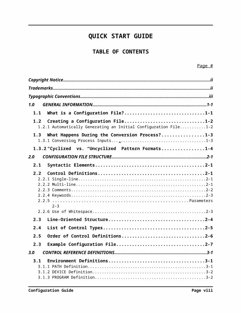
QUICK START GUIDE
TABLE OF CONTENTS
Page #
Copyright Notice.................................................................................................................................... ii
Trademarks............................................................................................................................................ ii
Typographic Conventions..................................................................................................................... iii
1.0 GENERAL INFORMATION.................................................................................................1-1
1.1 What is a Configuration File?...........................................................................................1-1
1.2 Creating a Configuration File...........................................................................................1-21.2.1 Automatically Generating an Initial Configuration File................................................................1-2
1.3 What Happens During the Conversion Process?.............................................................1-31.3.1 Conversion Process Inputs............................................................................................................ 1-3
1.3.2 “Cyclized” vs. “Uncyclized” Pattern Formats..................................................................1-4
2.0 CONFIGURATION FILE STRUCTURE..............................................................................2-1
2.1 Syntactic Elements............................................................................................................2-1
2.2 Control Definitions............................................................................................................2-12.2.1 Single-line.................................................................................................................................... 2-12.2.2 Multi-line..................................................................................................................................... 2-12.2.3 Comments.................................................................................................................................... 2-22.2.4 Keywords..................................................................................................................................... 2-32.2.5 Parameters................................................................................................................................... 2-32.2.6 Use of Whitespace....................................................................................................................... 2-3
2.3 Line-Oriented Structure...................................................................................................2-4
2.4 List of Control Types........................................................................................................2-5
2.5 Order of Control Definitions.............................................................................................2-6
2.3 Example Configuration File..............................................................................................2-7
3.0 CONTROL REFERENCE DEFINITIONS...........................................................................3-1
3.1 Environment Definitions...................................................................................................3-13.1.1 PATH Definition.......................................................................................................................... 3-13.1.2 DEVICE Definition...................................................................................................................... 3-23.1.3 PROGRAM Definition................................................................................................................. 3-23.1.4 Complete Program Path Example.................................................................................................3-2
3.2 Cyclization Timing Definitions.........................................................................................3-3
3.3 PERIOD Definition...........................................................................................................3-3
3.4 EDGES Definition.............................................................................................................3-5
3.5 PINLIST Definition...........................................................................................................3-6
3.6 GROUP Definition............................................................................................................3-7
Configuration Guide Page vii
3.7 DC Levels..........................................................................................................................3-7
3.8 Custom Timing..................................................................................................................3-8
3.9 Power Sequences.............................................................................................................3-103.9.1 Power down sequencing............................................................................................................. 3-10
3.10 TEST Definitions.............................................................................................................3-11
3.11 FLOW Definitions...........................................................................................................3-14
4.0 CUSTOMIZING PATTERNS................................................................................................4-1
4.1 Starting Syntax..................................................................................................................4-2
4.2 Mask Syntax......................................................................................................................4-2
4.3 Masking examples.............................................................................................................4-4
4.4 BASE Syntax....................................................................................................................4-5
4.5 Command & commandParameterList Syntax.......................................................................4-5
Configuration Guide Page viii

1.0 General Information
1.0 GENERAL INFORMATION
Configuration Guide

1.0 General Information
1.0 GENERAL INFORMATION
A brief look at what a Velocity CAE configuration file entails and how it is create and used.
1.1 What is a Configuration File?
A Configuration File is a human-readable, ASCII text file used by Velocity to control the conversion process.
Some of the aspects of the conversion process that a Configuration File controls are:
The directory into which files generated by the conversion are to be written
The period by which a VCD pattern is to be divided into cycles
The target pin list, including test system resource assignments
Pin groups
Custom timing
Custom levels
Rules for creating custom patterns from existing patterns
Standardized test and power up/down definitions
Test flow
Every Velocity conversion – whether the DIAMOND ShellConstructor or Design-to-Test (D2T) or Tester-to-Tester (T2T) – requires the use of a Configuration File.
If the user does not specify a Configuration File and attempts to run a conversion, Velocity will display the following error message:
Configuration Guide Page 1

1.0 General Information
Configuration Files can be given any name, within the limitations of the host operating system. But, all names use a .cfg extension. They can reside in any directory that the user chooses.
1.2 Creating a Configuration File
As a human-readable, ASCII text file, a Configuration File can be created and edited using any text editor. The user may choose to start from nothing and create the entire Configuration File in the text editor; or, use an existing file as a template and edit those elements which differ.
As an alternative, Velocity offers a way to speed up the Configuration File creation process. The Velocity GUI can quickly and automatically generate an initial Configuration File from an existing pattern file that is to be converted.
The automatic process will create a file containing, at a minimum, the definition of the target file path and the pin list. The user can then add any other required elements in the text editor.
1.2.1 Automatically Generating an Initial Configuration File
From the GUI Configuration menu, select New.
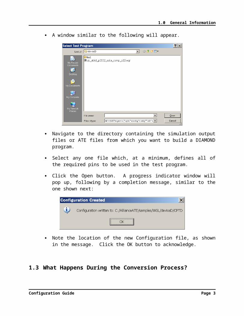
A window similar to the following will appear.
Configuration Guide Page 2

1.0 General Information
Navigate to the directory containing the simulation output files or ATE files from which you want to build a DIAMOND program.
Select any one file which, at a minimum, defines all of the required pins to be used in the test program.
Click the Open button. A progress indicator window will pop up, following by a completion message, similar to the one shown next:
Note the location of the new Configuration file, as shown in the message. Click the OK button to acknowledge.
1.3 What Happens During the Conversion Process?
In order to better understand the aspects of the pattern conversion process that are controlled by the Configuration File, it is useful to have a basic understanding of what happens during conversion.
1.3.1 Conversion Process Inputs
Configuration Guide Page 3
1.0 General Information
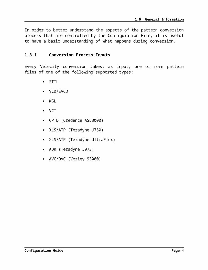
Every Velocity conversion takes, as input, one or more pattern files of one of the following supported types:
STIL
VCD/EVCD
WGL
VCT
CPTD (Credence ASL3000)
XLS/ATP (Teradyne J750)
XLS/ATP (Teradyne UltraFlex)
ADR (Teradyne J973)
AVC/DVC (Verigy 93000)
Configuration Guide Page 4
1.0 General Information
1.3.2 “Cyclized” vs. “Uncyclized” Pattern Formats
ATE test systems, such as the Credence Diamond, output functional stimulus to the device (and sample functional responses from the device) in the form of a vector sequence. The vectors are presented at a particular rate defined by the cycle time (also known as the period).
The following are excerpts from a Diamond STIL pattern file and timing file, respectively, showing how digital pattern sequences and corresponding cycle timing are represented in an ATE environment:
///////////////////////////////////////////////////////////////////////////// Pattern Block: example_vectors///////////////////////////////////////////////////////////////////////////Pattern example_vectors {Start_example_vectors:
W "tps66000_10000";V { all =
0XXXXXXXXXXXXXXXXXXXZX00XXXXXX1XXXXXXX1XXXXX0X00X00XXXX1X; } //0V { all =
0XXXXXXXXXXXXXXXXXXXZX00XXXXXX1XXXXXXX1XX0XX0X00X00XXXX1X; } //1
///////////////////////////////////////////////////////////////////////////// Timing Blocks///////////////////////////////////////////////////////////////////////////Timing "customTiming" {
WaveformTable "tps66000_10000" {Period 'PERIOD';Waveforms {
"addr[10]" {01Z { '0.000*PERIOD' D/U/Z;}LHXM { '0.091*PERIOD' L/H/X/T;}
}"addr[11]" {
01Z { '0.000*PERIOD' D/U/Z;}LHXM { '0.091*PERIOD' L/H/X/T;}
}
Many other simulation and test data formats, such as WGL (Waveform Generation Language), also have a concept of vectors and cycle times, which can be translated to Diamond format in a relatively straightforward manner. These kinds of pattern formats can be categorized as cyclized formats.
The following are excerpts from a WGL file, showing how digital pattern sequences and cycle timing, corresponding to the STIL example above, are represented in a WGL format:
Configuration Guide Page 5

1.0 General Information
pattern Chain_Scan_test("extal", "dft_setup", "dft_atpg", "dft_shift", … { Pattern 0 Cycle 0 Loop 0 } vector(+, tps66000_10000) := [ 0 0 0 0 0 0 0 - - - - - - - - - - … { Chain_test } { Pattern 0 Cycle 1 Loop 1 } { Begin chain test } repeat 6 vector(+, tps66000_10000) := [ 0 1 0 0 0 0 0 - - - - - - - -
timeplate tps66000_10000 period 66000ps … "addr[10]" := input[0ps:S]; "addr[11]" := input[0ps:S]; … "addr[10]" := output[0ps:X, 6000ps:Q'edge]; "addr[11]" := output[0ps:X, 6000ps:Q'edge];
OBSERVATIONS:
1. In the above comparison of STIL and WGL formats, the pins were not defined in the same order; so, the vector columns will not match up. However, the same underlying vector data, per pin, would be contained in each format.
2. In the DIAMOND STIL example on the previous page, note how vectors and cycle timing are brought together by preceding a sequence of vector lines (those lines that begin with “V”) with a waveform table selection line beginning with “W”. The waveform table specified after the “W” is defined within the Timing Block shown on the same page.
3. In the WGL example above, cycle timing is defined within a timeplate definition, and then brought together with vectors in individual vector lines (those lines containing the keyword vector), by referencing the timeplate name.
Not all pattern formats are cyclized. The most notable examples of non-cyclized formats are the VCD (Verilog Change Dump) and EVCD (Extended Verilog Change Dump) formats. In these non-cyclized formats, signal patterns are represented as a continuous stream of events, where an event is a change of state at a particular point in time relative to the beginning of the pattern.
The following is an excerpt from an example VCD file:
Configuration Guide Page 6

1.0 General Information
…#1000pT 0 0 <262pT 0 0 <263pX 6 0 <265pX 6 0 <266pL 6 0 <267
#3000pb 6 6 <9pb 6 6 <10pb 6 6 <11pb 6 6 <12
#4000pN 6 6 <96pN 6 6 <97 …
OBSERVATIONS:
1. The lines beginning with “#” are timestamps, with the time unit being specified previously in the file with the $timescale statement. (In this example, the time unit is 1 ps; so, 1000 represents 1 ns.)
2. Following each timestamp line is a sequence of value change lines, one for each signal which changes state at that timestamp. (Signals which do not change state at that timestamp are not listed.)
3. The first field of each value change line is the state to which the signal changes. The fourth field is an arbitrary, user-defined symbol for a specific signal.
For VCD, Velocity will analyze the spacing of timing events for each signal, and determine a best-fit tester cycle time and edge delays for your DIAMOND test program.
Configuration Guide Page 7

2.0 Configuration File Structure
2.0 CONFIGURATION FILE STRUCTURE
Configuration Guide

2.0 Configuration File Structure
2.0 CONFIGURATION FILE STRUCTURE
Information on how to the Velocity CAE file is structured and the syntax involved for creating the configuration file.
2.1 Syntactic Elements
Configuration Files are made up of a number of different types of syntactic elements.
At the top level, there are two main types of elements. These types are:
Control Definitions, which define particular aspects of the conversion and program generation process; and,
comments, which begin with the ‘#’ symbol and continue to the end of the line.
2.2 Control Definitions
Control Definitions can be categorized into two forms: single-line and multi-line.
2.2.1 Single-line
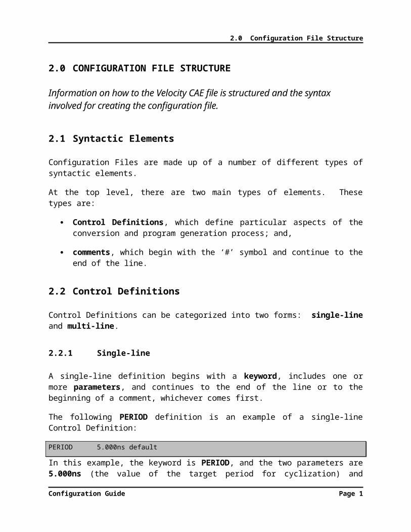
A single-line definition begins with a keyword, includes one or more parameters, and continues to the end of the line or to the beginning of a comment, whichever comes first.
The following PERIOD definition is an example of a single-line Control Definition:
PERIOD 5.000ns default
In this example, the keyword is PERIOD, and the two parameters are 5.000ns (the value of the target period for cyclization) and default (the name given to this particular target period, or Clock Domain).
2.2.2 Multi-line
Configuration Guide Page 1

2.0 Configuration File Structure
A multi-line definition (also called a block) consists of a starting line, zero or more sub-parameter lines, and an ending line.
Starting Line
The starting line begins with a keyword and includes zero or more parameters.
Sub-parameter Line
A sub-parameter line consists of one or more keywords and/or user-defined symbols or values whose order depends on the type of Control Definition. Each line provides further details in the definition of the Control.
Ending Line
The ending line consists of the keyword END followed by the starting line keyword.
The following PINLIST block definition is an example of a multi-line Control Definition:
PINLISTANALOG_VDD default IO ANALOG_VDDCVDD default IO CVDDHOLDn default IO HOLDn
END PINLIST
Note that the block begins with a starting line consisting only of the keyword PINLIST and ends with an ending line consisting of END PINLIST. In between are sub-parameter lines that begin with a pin name and consist of several parameters that define properties of the pin.
2.2.3 Comments
Comments can appear anywhere within the Configuration File, with the following restrictions:
They only extend to the end of the line. Multi-line comments require a separate starting “#” for each line.
Everything from the starting “#” to the end of the line is part of the comment. No part of a Control Definition will be recognized by Velocity if placed after the “#”.
If a comment is placed at the end of a Control Definition line, the starting “#” must be separated from the last Control Definition line character by
Configuration Guide Page 2
2.0 Configuration File Structure
whitespace. (See below for more information on the use of whitespace in Configuration Files.)
The following is an example of a multi-line comment in a Configuration File, with the comment on each line taking up the entire line:
############################################################################# PinList Definition###########################################################################
The following is an example of a comment at the end of a Control Definition line (in this case, the starting line of a TEST definition block):
TEST contNegative 150 # Continuity test with negative forcing current
2.2.4 Keywords
Keywords are Velocity reserved words. That is, they may not be used for user-defined names, such as ClockDomain names, Pin names, and Pattern names.
Keywords are NOT case-sensitive. For example, Velocity would interpret period the same as PERIOD or, even pErIoD. However, for readability purposes and for establishing a standard convention, it is recommended that all keywords be in UPPER-CASE.
2.2.5 Parameters
Parameters are elements of a Control Definition that allow the user to provide details for a particular instance of the Control. The user does so by giving a user-defined symbol or value, called an argument, at the corresponding parameter location.
For example, the first parameter in the starting line of the TEST block definition is the test name. In the example above, the argument for that parameter is “contNegative”.
Arguments for parameters ARE case-sensitive. So, a later test flow definition referencing the TEST called “contNegative” would have to specify the exact same case.
2.2.6 Use of Whitespace
Whitespace in a Configuration File includes spaces and tabs.
Configuration Guide Page 3

2.0 Configuration File Structure
A Configuration File may contain any amount of whitespace at the beginning and end of lines, and between keywords, parameters, and comments. Some parameters, such as the pin list of a PINS masking definition, can be specified with multiple sub-elements separated by a non-whitespace character. The following example shows a PINS sub-parameter definition within a PATTERN block definition:
PATTERN func_pat_masked PINS Q0,Q1,Q2,Q3 55-83END PATTERN
Note that the pin list, “Q0,Q1,Q2,Q3”, is considered the argument to one parameter of the PINS definition. Therefore, it contains no embedded whitespace. The individual sub-elements (Pins in this case) are separated only by commas. Likewise, the cycle range parameter is made up of a start and stop address separated by a hyphen.
Configuration Guide Page 4

2.0 Configuration File Structure
2.3 Line-Oriented Structure
The main elements of a Configuration File – Control Definitions and Comments – follow, for the most part, a line-oriented structure. That is, the end-of-line (i.e. carriage return) marks the end of:
Single-line Control Definitions;
Starting and Ending lines of Multi-line Control Definitions;
Sub-parameter lines of Multi-line Control Definitions (with exceptions noted below); and,
Comments.
The only exceptions to the end-of-line termination are the masking sub-parameter definitions – ON, OFF, and PINS – of a PATTERN block definition. Those sub-parameter definitions are terminated by a semicolon (;) and are allowed to extend to multiple lines. This feature allows for long, complex masking definitions. Refer to the detailed description of the PATTERN block syntax later in this guide.
Also, as noted in the previous section of this guide on Comments, a Control Definition line may be terminated by the beginning of a Comment on the same line.
All Velocity CAE tools require a configuration file, which is a human-readable ASCII text file that you create. This file will customize the Core Analyzer Engine for specific conversions. For more information on understanding, creating, and editing Velocity configuration files, refer to the section in this guide called “Configuration Files,” or for more details see the Velocity CAE Configuration Guide.
To start a new conversion without customization you can run Velocity CAE with a blank configuration file.
Configuration Guide Page 5

2.0 Configuration File Structure
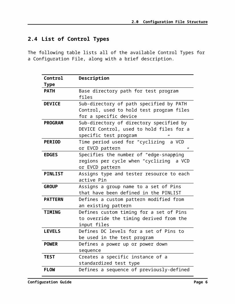
2.4 List of Control Types
The following table lists all of the available Control Types for a Configuration File, along with a brief description.
Control Type
Description
PATH Base directory path for test program files
DEVICE Sub-directory of path specified by PATH Control, used to hold test program files for a specific device
PROGRAM Sub-directory of directory specified by DEVICE Control, used to hold files for a specific test program
PERIOD Time period used for “cyclizing” a VCD or EVCD pattern
EDGES Specifies the number of “edge-snapping” regions per cycle when “cyclizing” a VCD or EVCD pattern
PINLIST Assigns type and tester resource to each active Pin
GROUP Assigns a group name to a set of Pins that have been defined in the PINLIST
PATTERN Defines a custom pattern modified from an existing pattern
TIMING Defines custom timing for a set of Pins to override the timing derived from the input files
LEVELS Defines DC levels for a set of Pins to be used in the test program
POWER Defines a power up or power down sequence
TEST Creates a specific instance of a standardized test type
FLOW Defines a sequence of previously-defined TEST instances to be inserted into the test program
Configuration Guide Page 6

2.0 Configuration File Structure
2.5 Order of Control Definitions
Many of the Control Definitions can reference elements that are defined in other Control Definitions elsewhere in the Configuration File. For example, a TIMING block definition can reference a Pin defined in the PINLIST block or a Group defined in a GROUP definition.
Elements must be defined in a Configuration File before they can be referenced. Therefore, the order of Control Definitions within the file is important. The order of the Control Types shown in the previous table is the recommended order in which those types should be defined.
NOTE: It is not necessary to define every Control Type in a Configuration File. Velocity uses a default set of properties and behaviors for those aspects of a conversion not defined in the Configuration File. Only those Control Types with properties
which differ from the defaults need to be defined.
Configuration Guide Page 7
2.0 Configuration File Structure
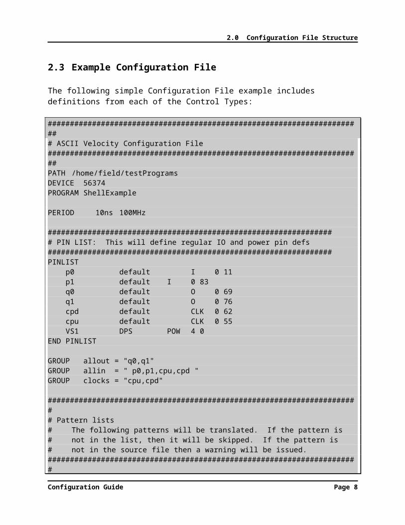
2.3 Example Configuration File
The following simple Configuration File example includes definitions from each of the Control Types:
######################################################################## ASCII Velocity Configuration File#######################################################################PATH /home/field/testProgramsDEVICE 56374 PROGRAM ShellExample
PERIOD 10ns 100MHz
################################################################# PIN LIST: This will define regular IO and power pin defs################################################################PINLIST p0 default I 0 11 p1 default I 0 83 q0 default O 0 69 q1 default O 0 76 cpd default CLK 0 62 cpu default CLK 0 55 VS1 DPS POW 4 0END PINLIST
GROUP allout = "q0,q1"GROUP allin = " p0,p1,cpu,cpd "GROUP clocks = "cpu,cpd"
####################################################################### Pattern lists# The following patterns will be translated. If the pattern is# not in the list, then it will be skipped. If the pattern is# not in the source file then a warning will be issued.######################################################################PATTERN multipleLoop BASE SpecFunc LOOP 5,10 16 LOOP 16,20 16END PATTERN
##################################################################### Timing and Levels
Configuration Guide Page 8

2.0 Configuration File Structure
# definitions will define the values of specs. The following# values will be assigned by default. Groups and pins can# be defined to override defaults by using a pin name or group# name.####################################################################TIMING default period 100ns offset 0ns duty 50% drive 25% receive 90%END TIMING
LEVELS default POWER 3.3V VIL 10% VIH 90% VOL 40% VOH 60%END LEVELS
####################################################################### Power up and power down######################################################################POWER nominal
VS1 1.25V 500mA 5uS END POWER
################################################################## Test Definitions# The following tests will be defined as discrete functions# that can be executed as user commands or as part of flows# or as modified in C++ user_main.#################################################################TEST contNegative 150 TYPE cont FORCE -10uA CLAMP 2V LOW 400mV HIGH 800mV PINS ALLEND TEST
TEST funcSpec 1 TYPE func PATTERN SpecFunc END TEST
#############################################################
Configuration Guide Page 9
2.0 Configuration File Structure
# Flow Definition# The following tests will be executed in the following# order. If no flow is defined, then all the tests will# be included in the order they are defined. All will# be called inside user_main#############################################################FLOW experimentName TEST contNegative POWER nominal TEST funcSpec DELAY 15ms POWER offEND FLOW
Configuration Guide Page 10

3.0 Control Definition Reference
3.0 CONTROL DEFINITION REFERENCE
Configuration Guide

3.0 Control Definition Reference
3.0 CONTROL REFERENCE DEFINITIONS
3.1 Environment Definitions
The Environment section of the Configuration File consists of a set of definitions that define the location of the target test program files. Typically, this is the first section in a Configuration File.
Velocity divides the test program location into three parts:
base path – Typically, points to the directory used as the parent directory of all DIAMOND test programs.
Device name – Appended to the base path. Categorizes test programs by device.
Program name – Appended to the base path / Device name combination. Contains all the files that make up a specific DIAMOND test program.
The three parts of the test program directory path are defined by the following Control Types:
PATH
DEVICE
PROGRAM
3.1.1 PATH Definition
Syntax:
PATH pathName
where,pathName is a directory path specifier
Example:PATH /home/DIAMONDprograms
Configuration Guide Page 1

3.0 Control Definition Reference
NOTE: The directory path specifier must use valid syntax for the underlying file system.
3.1.2 DEVICE Definition
Syntax:
DEVICE directoryName
where,directoryName is the name of a directory
Example:DEVICE coolChip
3.1.3 PROGRAM Definition
Syntax:
PROGRAM directoryName
where,directoryName is the name of a directory
Example:PROGRAM finalTest
3.1.4 Complete Program Path Example
Using the PATH, DEVICE, and PROGRAM Definitions in the above examples, Velocity would create test program files for the DIAMOND Build in the directory
/home/DIAMONDprograms/coolChip/finalTest
Configuration Guide Page 2
3.0 Control Definition Reference
3.2 Cyclization Timing Definitions
The Cyclization Timing section of the Configuration File is used mainly for controlling the conversion of VCD and EVCD patterns, where the stream of events needs to be divided into tester cycles.
BACKGROUND: For more information on VCD/EVCD patterns and cyclization, refer to the previous chapter in this guide called “What Happens During the Conversion Process?”, and, specifically, the section called “’Cyclized’ vs. ‘Uncyclized’ Pattern Formats”.
The two Control Types used for controlling cyclization are:
PERIOD
EDGES
3.3 PERIOD Definition
The PERIOD definition specifies the time period used for “cyclizing” a VCD or EVCD pattern. A Configuration File can include one or more PERIOD definitions. In the case of multiple definitions, each definition will apply to a different group of Pins to be defined in the subsequent PINLIST block.
Velocity will attempt to divide the VCD/EVCD event stream into the specified period, and determine the resulting drive, tri-state, and compare edge delays within the period.
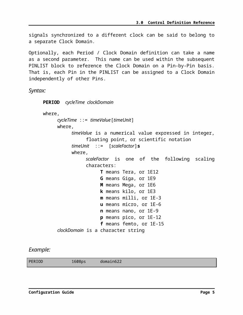
The period that is specified by a PERIOD definition is also known in Velocity as a Clock Domain. The term Clock Domain comes from the fact that devices with synchronous, digital functionality typically have a group of signals whose timing is referenced to a particular clock signal. Therefore, those signals can share the same test system period as the clock. Some devices have multiple clocks operating at different rates, each clock having an associated group of signals synchronized with it. Each group of signals synchronized to a different clock can be said to belong to a separate Clock Domain.
Optionally, each Period / Clock Domain definition can take a name as a second parameter. This name can be used within the subsequent PINLIST block to reference the Clock Domain on a Pin-by-Pin basis. That is, each Pin in the PINLIST can be assigned to a Clock Domain independently of other Pins.
Syntax:
PERIOD cycleTime clockDomain
Configuration Guide Page 3

3.0 Control Definition Reference
where,cycleTime ::= timeValue[timeUnit]where,
timeValue is a numerical value expressed in integer, floating point, or scientific notation
timeUnit ::= [scaleFactor]swhere,
scaleFactor is one of the following scaling characters:T means Tera, or 1E12G means Giga, or 1E9M means Mega, or 1E6k means kilo, or 1E3m means milli, or 1E-3u means micro, or 1E-6n means nano, or 1E-9p means pico, or 1E-12f means femto, or 1E-15
clockDomain is a character string
Example:PERIOD 1608ps domain622
Note: The time value parameter can include units immediately after the number (no whitespace in between). Units can include all the common scaling letters, such as n (for nano), u (for micro), m (for milli), etc. Also note that the name “domain622” has been
assigned to the Clock Domain.
Configuration Guide Page 4
3.0 Control Definition Reference
3.4 EDGES Definition
The EDGES definition specifies the number of “edge-snapping” regions per cycle when “cyclizing” a VCD or EVCD pattern. This corresponds with the +eN command-line option for edge snapping resolution and the Snap Resolution field in the GUI.
Edge snapping is useful for VCD/EVCD patterns in which the simulation was imperfect and produced edges that varied in time within the clock period from cycle to cycle. Just as many drawing software tools allow a drawn point to “snap” to the nearest grid point, so edge snapping allows an existing edge to be moved automatically to a specific reference time within a cycle.
When edge snapping is enabled for a Velocity conversion, each cycle or period is divided into a number of equal-size regions, as specified by the EDGES definition. Any input edge that falls within a particular snap region will be moved to the earliest time in the region; whereas, any output edge will be moved to the latest time in the region.
WARNING! Make sure to specify a number of edges at least as great as the maximum number of edges expected per cycle for any defined Pin. Otherwise, edges will be lost!
For example, if a clock signal exists with two edges – rising and falling – per period, then specify 2 edges. If the number of edges were specified as 1, then both the rising and falling edge of the
clock would be snapped to the beginning of the snap region (the period) and the pulse would be lost.
The number of edges specified by the EDGES definition takes precedence over any number of edges specified in a converter command-line option or within the Velocity GUI. This feature helps ensure that the user does not accidentally specify too few snap edges and thus lose edges in the pattern. (See the WARNING above.)
Syntax:
EDGES numberOfEdges
where,numberOfEdges is an integer value
Configuration Guide Page 5

3.0 Control Definition Reference
Example:EDGES 2
3.5 PINLIST Definition
Syntax:
PINLIST
pinName resource pinType [slot] [channel] [alias1 [alias2…aliasN]]
END PINLIST
The PINLIST block defines, per pin, the DIAMOND tester channel assigned and any alternate versions of that name used in the simulation or ATE conversion source.
The tester channel information that can be specified includes:
Resource Type: DPIN96, DPS16, VIS16, DIBU, or default. (The word default selects DPIN96.)
Pin Type: I, O, IO, CLK, REF, POW, A, NC, or R. (See the Velocity Program Generator User’s Guide for more information on these types.)
Slot number
Channel number
The alternate pin names are known as Aliases. You can specify as many Aliases on a pin line – separated by whitespace – as you need. Velocity uses Aliases to match simulation or ATE pin names that are different from the target DIAMOND pin name.
The following is an example of a PINLIST definition:
############################################################################# PinList Definition###########################################################################PINLIST
ANALOG_VDD DPS16 POW 0 2HOLDn DPIN96 I 1 17 hold_n holdnWPn DPIN96 O 1 8 wp_nanapadext_data_n VIS16 ANA 0 3
END PINLIST
Configuration Guide Page 6
3.0 Control Definition Reference
Pin ANALOG_VDD uses channel 2 of a DPS16 card in slot 0.
Also, note that pin HOLDn has aliases of hold_n and holdn, meaning that it can take its data from simulation or ATE conversion sources that use either of those alias names.
3.6 GROUP Definition
The GROUP Control definition allows you to assign a name to a group of pins, for easier reference elsewhere in the Configuration file.
To define a Group, use the keyword GROUP followed by a Group name, followed by an equals sign (=) and a comma-separated list of pin names enclosed in double-quotes (“”). The following is an example of a Group definition:
GROUP DBUS = “D0, D1, D2, D3, D4, D5, D6, D7”
3.7 DC Levels
BACKGROUND: Simulation output files, and even STIL files, do not typically define DC levels for the signals. However, using configuration file structures, Velocity provides you with a way to include levels information with your auto-generated DIAMOND test program.
The LEVELS block allows you to define, for any pin or group of pins, power supply levels, input drive levels, and output threshold levels.
To define levels for a group of pins, create the following Control definition block.
On the first line, use the keyword LEVELS followed by a pin or group name. Optionally, you can use the word default for the pin specification to indicate all pins.
On the next line, use the keyword POWER followed by a voltage value. This will be the master power supply voltage level.
On subsequent lines, use the following keywords followed either by a voltage value or a percentage:
VIH – Input voltage for a logic high
Configuration Guide Page 7

3.0 Control Definition Reference
VIL – Input voltage for a logic lowVOH – Output threshold voltage for a logic highVOL – Output threshold voltage for a logic low
BACKGROUND: If you specify a level as a percentage, Velocity interprets it as a percentage of the POWER level. This provides a convenient way to scale levels with a device power supply voltage.
For the last line, use the keywords END LEVELS.
The following is an example of a Levels definition:
LEVELS default POWER 3.0V VIL 0.8V VIH 2.0V VOL 30% VOH 50%END LEVELS
3.8 Custom Timing
BACKGROUND: Although Velocity will create appropriate Time Sets for your DIAMOND program, based on the simulation or ATE files used as source for the conversion, you can create your own custom timing to apply to tests.
To define custom timing for a group of pins, create the following Control definition block.
On the first line, use the keyword TIMING followed by a pin or group name. Optionally, you can use the word default for the pin specification to indicate all pins.
On the next line, use the keyword PERIOD followed by a time value. This will be the period of the tester’s pattern sequencer.
Configuration Guide Page 8

3.0 Control Definition Reference
BACKGROUND: All TIMING blocks in a particular Configuration file must use the same PERIOD value. This ensures that the DIAMOND will be able to use the resulting STIL file.
TIP: In order to use TIMING blocks with different PERIOD values in your test program, use separate Configuration files for each of the different periods and run separate conversions with each.
Configuration Guide Page 9

3.0 Control Definition Reference
On subsequent lines, use the following keywords followed either by a time value or a percentage:
DRIVE – Time delay of a drive edge for a pin of type I or IORECEIVE – Time delay of a compare edge for a pin of type O or IOPULSE – Duration of a pulsed waveform for a pin that is not defined as a clock pin.OFFSET – Time delay of first edge for a pin of type CLKRISE – Time delay of second edge for a pin of type CLK, if a rising edgeFALL – Time delay of second edge for a pin of type CLK, if a falling edgeDUTY – Duty cycle for a pin of type CLK, expressed only as a percentage
BACKGROUND: If you specify a timing parameter as a percentage, Velocity interprets it as a percentage of the PERIOD time. This provides a convenient way to scale edge delays with a sequencer period.
For the last line, use the keywords END TIMING.
The following is an example of a Timing definition:
################################################################ Timing# These definitions will define the values of specs # values will be assigned by default. Groups and pins can# be defined to override defaults by using a pin or group# name.###############################################################TIMING default period 100ns offset 0ns duty 50% drive 25% receive 90%END TIMING
Configuration Guide Page 10

3.0 Control Definition Reference
3.9 Power Sequences
This section is used to define the power up sequence. Although this section is technically optional, It is strongly suggested that this section be used. Otherwise, the power up will require user intervention in multiple locations in the source files. Syntax of this block is as follows
POWER powerStateNameSupplyName supplyVoltage clampCurrent delayAfterSupplyName supplyVoltage clampCurrent delayAfterSupplyName supplyVoltage clampCurrent delayAfter“” “” “” “”“” “” “” “”
END POWER
When used, this power sequence can be referenced in the same way that test’s (defined next) are used. In other words, this block is treated as a special case of the tests that will allow execution with name pass/fail queries. The power sequence will always result in a pass value and will never log anything.
If a staged power up or power down sequence is required. This can be defined by generating multiple power blocks with unique names for each stage. Or, it can be defined explicitly within a single power block by defining the supply more than once in the block.
Each entry in the power block is executed serially in the order is defined in the configuration.
Multiple supplies can be referenced within a single block
At the end of execution, supplies will retain the supply value last requested
The following is an example of a Power definition:
####################################################################### Power up and power down######################################################################POWER nominal
VS1 1.25V 500mA 5uS VS2 3.3V 500mA 0uSVS3 3.3V 500mA 0uS
END POWER
Configuration Guide Page 11

3.0 Control Definition Reference
3.9.1 Power down sequencing
There will always be a power sequence named “off” created by the ShellConstructor. This default sequence will do nothing more than disconnecting the power supplies. This default sequence will be overridden in the following cases.
Power off case 1: If only one power up sequence is defined, the power off sequence will be assumed to occur in reverse order. Each supply will be set to 0V and then disconnected in the reverse order of the power up
Power off case 2: If multiple power up sequences are defined, the power off will default to the reverse order of the last power sequence. Each supply will be set to 0V and then disconnected in the reverse order of the power up
Power off case 3: If a special power down that is not explicitly equivalent to one of the above, a special POWER block named “off” can be defined that will automatically override the default case. This is the recommended method
3.10 TEST Definitions
This section is used to create specific test instances. Each defined test will be accessible from both the main test program and command line execution scripts. The general syntax for the section is as follows. Each entry is then detailed
TEST testname testnumberTYPE typeKeywordPARM PARMvaluePARM2 PARM2value“” “”“” “”
END TEST
TEST: Keyword to tell the Velocity that a new test block is being created. This then requires that a unique test name and(optionally) a unique test number to follow. The testname will be the name as accessed by the command line execution script. Each test must have a unique name. The test number will provide a starting testnumber for every element logged. The test numbers should be unique and enough separated from one another so that tests will multiple events will not step on one another.
Configuration Guide Page 12

3.0 Control Definition Reference
TYPE: The keyword should be the first subparameter of each TEST block. This will tell the Velocity what type of generic function is to be applied. Depending on which parameter type is received, a different set of parameters will then be defined. The typeKeyword can be one of the following values. The parameters that are required for each test type are also defined
func: Functional Test executes a digital pattern and responds with pas/fail results PATTERN: Pattern Block name that is to be executed. Note: This pattern
name refers to the block name which may be different from the STIL file name that is derived from. The user must know the exact name for this to be valid. This parameters associated value will be case sensitive. Alternatively, “$default” can be used for the pattern’s name and the pattern will be chosen automatically from the input pattern list.
TIMING: Defines the Timing Block that should be used for a given test. LEVELS: Defines the DCLevels Block that should be used for a given test. ACSPEC: Defines the Timing Spec category that should be used for a given
test. DCSPEC: Defines the Level Spec category that should be used for a given
test.
cont: Continuity Test - tests a lists of pins for connectivity by examining voltage seen when small current is applied to pin with no power applied
FORCE : Force current value for the continuity test CLAMP: Clamp Value for voltage measurement. This will be the maximum
possible voltage that will be received on the active pin LOW: Low value for the continuity voltage measurement HIGH: High Value for the continuity voltage measurement PINS: pin or group name that is to be used for the test. Each pin within a group
will be tested individually.
shrt: Shorts Test - tests a lists of pins for connectivity by examining current seen when small voltage is applied to pin with no power applied
FORCE : Force voltage value for the shorts test CLAMP: Clamp Value for current measurement. This will be the maximum
possible current that will be received on the active pin LOW: Low value for the continuity current measurement HIGH: High Value for the continuity current measurement PINS: pin or group name that is to be used for the test. Each pin within a group
will be tested individually.
leak: Leakage Test – Test current leakage on a given pin when particular voltages are applied to the given pin
FORCE : Force Voltage value for the leakage test LOW: Low value for the continuity current measurement
Configuration Guide Page 13
3.0 Control Definition Reference
HIGH: High Value for the continuity current measurement PINS: pin or group name that is to be used for the test. Each pin within a group
will be tested individually.
iddq: Static IDDQ test. Applies a given functional pattern, stops a given vector location and measures the power supply current at that test point
PATTERN: Name of functional pattern that is to be used for the given test PINS: supply or group of supplies that is to be tested LOW: Lowest valid current value that is allowed HIGH: Highest possible current value that is allowed STOP: comma delimited list of vector numbers or label names that are to be
included in the test. This can also refer to a range of numbers by using the dash (“-“). For example, “10,11,12,13” would result in the same set of IDDQ stop locations as “10-13”.
The following is a sample Test Blocks section that defines a number of tests. Specifically, this list of definitions will result in 8 specifically accessible test Functions defined in TestFunctions.cpp using the generic AC and DC test functions defined in GenericFunction.cpp. There will then be 8 script execution functions defined in user_commands.cpp. These functions are also available to the Flow Block section of the configuration defined below which can be used to create instances of these functions in a user defined order in the “main” program.
The following is an example of a Test definition:
################################################################## Test Definitions# The following tests will be defined as discrete functions# that can be executed as user commands or as part of flows# or as modified in C++ user_main.#################################################################TEST funcSpec 1 TYPE func PATTERN SpecFunc END TEST
TEST shortsPositive 100 TYPE shrt FORCE 10uV CLAMP 1mA LOW 400mA HIGH 800mA PINS ALL
Configuration Guide Page 14

3.0 Control Definition Reference
END TEST
TEST contNegative 150 TYPE cont FORCE -10uA CLAMP 2V LOW 400mV HIGH 800mV PINS ALLEND TEST
TEST LeakageHi 250 TYPE leakage FORCE 3.3 LOW 10uA HIGH 50uA PINS allinEND TEST
TEST IDDQ 400 TYPE iddq PATTERN changeStartStop PINS vdd LOW 10uA HIGH 50uA STOP 15END TEST
TEST IDDQdouble 500 TYPE iddq PATTERN changeStartStop PINS vdd LOW 10uA HIGH 50uA STOP 15,16END TEST
3.11 FLOW Definitions
The testflow will insert a predefined set of tests in a particular order into the main program of the test. Each named test or power setting must be defined in prior to use or compilation errors will occur. This is the syntax for the section
FLOW flowNameTEST|POWER|DELAY testname|powerSequenceNam|delayValuee
Configuration Guide Page 15

3.0 Control Definition Reference
TEST|POWER|DELAY testname|powerSequenceNam|delayValuee‘’‘’
END FLOW
FLOW is a keyword that indicates the beginning of a flow block
Only one FLOW block should exist within a given test configuration. No errors will be seen but only the last flow listed will be inserted into the test program
testname and powerSequenceName must explicitly match a TEST or POWER block defined prior to the FLOW block
DELAY will insert delays in resulting test flow. There must be a number following the DELAY statement
The example below assumes that the 2 tests and 1 power sequence have already been defined. The “off” power sequence can either be explicitly defined or implied as being defined because it will automatically be generated because as the reverse of the defined power sequence.
The following is an example of a Flow definition:
############################################################## Flow Definition# The following tests will be executed in the following# order. If no flow is defined, then all the tests will# be included in the order they are defined. All will# be called inside user_main#############################################################FLOW experimentName TEST contNegative POWER nominal TEST funcSpec DELAY 15ms POWER offEND FLOW
Configuration Guide Page 16

4.0 Customizing Patterns
4.0 CUSTOMIZING PATTERNS
Configuration Guide

7.0 Reporting
4.0 CUSTOMIZING PATTERNS
BACKGROUND: If your Velocity package includes Optimization options, Velocity can automatically search for compression opportunities when converting patterns, and create appropriate repeats and loops in your DIAMOND STIL patterns.
However, even without Optimization, you can manually customize your pattern files using Configuration file control. With this
capability, you can specify explicitly not only repeats and loops, but also selective output masking (pin-by-pin and cycle-by-cycle).
Custom patterns are patterns that are created based on existing patterns but with additional sequencing features such as loops and breaks. By default, every custom pattern will have a base pattern that it is initially created from. After creation, the user can inject and arbitrary list of additional loops and branches to allow for varied execution of the predefined pattern. Therefore, this provides a simple way of automatically introducing modified execution of patterns when it is known beforehand that such changes should occur. Based upon STIL syntax, a number of additions will be made to the output STIL patterns.
First, a new STIL file will be created as a copy of the base pattern. Any labels that are used within the original will be renamed automatically so that they are unique in the copied version.
Second, any new sequences that are requested will be added to the new STIL file. Once compiled, they will be visible to the ITE PatternTool. Eventually, sequencing changes will also be allowed from the PatternTool. But, as of the writing of this document, these features are not yet enabled.
Third, PatternBurst and PatternExec blocks will automatically be created for the new pattern. TEST blocks can then refer to just the pattern name. The PatternExec will be implied. The timing associated with this pattern will be identical to that of the original base pattern. Therefore, no extra work will be required to force timing. This can always be changed but these changes will be made after the Shell is constructed as ITE already has tools to handle this type of activity. The shell, as stated in the introduction, is not meant to be the main user interface. But, rather, it is meant to provide a quick start for new test programs.
Configuration Guide Page 1

7.0 Reporting
4.1 Starting Syntax
The following syntax is used for the PatternBlock
PATTERN newPatternName[MASK
maskCommand maskPinList [conditions] maskCommand maskPinList [conditions]
END MASK]
BASE basePatternNameCommand commandParameterListCommand commandParameterList
END PATTERN
PATTERN: Keyword that tells the ShellConstructor that this is the beginning of a custom pattern block.
newPatternName: Must be a unique string to identify the name of the new pattern. This name can be used by subsequent TEST blocks.
MASK: Optional keyword to instruct the loader to begin a masking sequence for a loaded pattern. When active, this will replace active compare values of L or H with compare values of X. Input conditions will be left as they are in the loaded pattern.
4.2 Mask Syntax
maskCommand: This keyword will tell the mask loader what command is being requested. Masks can be turned on and off by cycle or pin by pin. Each command is terminated by a semicolon at the end of the line. This allows complicated or long statements to be spread over multiple lines
ON:
Masks can be turned on at any valid cycleNumber. This command will turn the masking on. Syntax is as follows
ON pin1,pin2…pinN cycleNumber [condition];
Each pin or group must be a valid pin or group as defined by the configuration. If no condition is defined, It will be assumed that the condition is always active after the given cycleNumber. If no subsequent OFF command exists for any pin, the mask will be active until the end of the pattern.. (Conditions explained below)
Configuration Guide Page 2
7.0 Reporting
OFF:
Masks can be turned off at any valid cycleNumber. This command will turn the masking off. Syntax is as follows
OFF pin1,pin2…pinN cycleNumber [condition];
Each pin or group must be a valid pin or group as defined by the configuration. If no condition is defined, It will be assumed that the condition is always active after the given cycleNumber. (Conditions explained below)
PINS
It may be desirable to handle each pins masking separately or collect all masking conditions in a single statement. The syntax is as follows
PINS pin1,pin2…pinN start1-stop1,start2-stop2 [condition];PINS pin1,pin2…pinN start1-END [condition];PINS pin1,pin2…pinN ALL [condition];
In this case, all of the starts and stops for a masking scheme are expressed in a a single comma delimited list. Start and stop pairs are separated by the “-“ (dash).
Each start and stop must be an integer that corresponds to a valid cycle number in the loaded pattern. The only exception to the integer limitation is the use of END which all apply the active maked region all te way to the end of a pattern. The other is the use of “ALL”, which will apply the mask to every cycle in the active pattern (Conditions explained below)
maskCondition:: Mask conditions can be used to fine tune the regions in which a mask is applied so to match conditions in the pattern on any pin at any state prior to the active cycle. Condition sequences will be analyzed as a comma delimited “or” of multiple conditions. Each condition is applied with the following sequence.
COND {[relativeCycle]]=”pinState” }
refPin: This is should be an explcit match to a pin in the given pin list. This can be equal to a pin the ON, OFF, or PINS state to which the condition is applied. Or, it may be equal to any other pin in the pin list as defined by the configuration
relativeCycle: This parameter is optional. If no relative cycle is defined, it is assumed to be 0 and will search for the condition on the active cycle that is potentially being masked.
pinState: This will define that state for the refPin that activates the given mask sequence. If the reference pin is not explicitly equal to the given state, then the mask will be deactivated.
Configuration Guide Page 3

7.0 Reporting
4.3 Masking examples
ON clkOut ALL; This will mask every cycle of the pin named clkOut
ON clkOut 0;OFF clkOut 100;
This will turn on masking for the pinNamed clkOut starting at cycle 0 and turning it off at cycle 100
ON clkOut 0;OFF clkOut 100;ON clkOut 1000;
This will turn on masking for the pinNamed clkOut starting at cycle 0 and turning it off at cycle 100. After this the mask will be turn on again at cycle 1000 and will remain active until the end of the pattern because no OFF statement occurs
PINS clkOut 0-100,1000-END; This will turn on masking for the pinNamed clkOut starting at cycle 0 and
turning it off at cycle 100. After this the mask will be turn on again at cycle 1000 and will remain active until the end of the pattern because no OFF statement occurs
PINS clkOut 0-100,1000-END RESET=”0”; This will turn on masking for the pinNamed clkOut starting at cycle 0 and
turning it off at cycle 100. After this the mask will be turn on again at cycle 1000 and will remain active until the end of the pattern because no OFF statement occurs. Within the active ranges, the mask will only be active if the RESET pin is set to 0. Therefore, if RESET is at any other state during the range, the clkOut pin will not be masked.
PINS clkOut 0-100,1000-END RESET[16]=”0”; This will turn on masking for the pinNamed clkOut starting at cycle 0 and
turning it off at cycle 100. After this the mask will be turn on again at cycle 1000 and will remain active until the end of the pattern because no OFF statement occurs. Within the active ranges, the mask will only be active if the RESET pin is set to 0 16 cycles prior to the active cycle. In other words, the mask will be active until the RESET pin has been set high for at least 16 cycles. This is usefull if a stability issue is being masked.
Configuration Guide Page 4

7.0 Reporting
4.4 BASE Syntax
BASE: Keyword to indicate that the new pattern is associated with a given base pattern.
basePatternName: This base pattern must be included in one of the input STIL patterns to the DIAMONDShell program. The name of the base pattern must explicitly match the name of the input STIL’s PATTERN block name.
4.5 Command & commandParameterList Syntax
The commands and associated parameters are an optional member of the Pattern Block. However, there will generally be at least one command inserted. Otherwise, there is no real reason to create the custom pattern in the first place. There is no upper limit on the number of inserted commands that can be used. However, when using loops is is important that these not be built to interleave. Only one level of looping is defined in this syntax The following actions can be inserted
LOOP
Loops can be added with the following syntaxLOOP startCycle,stopCycle [loopCount]
The start and stop cycle refer to the vector number of the beginning and ending of the inserted loop. A loop count is optional. If not defined, the loop count will be defined as infinite. The loop will have to be stopped by pressing the “abort” button in ITE, as the loop will be interpreted as infinite.
REPEAT
Single line repeats can be added with the following syntaxREPEAT cycle,loopCount
Cycle defines the vector number for a single line repeat. LoopCount defines the number of times that line should be executed. A loop count of 1 would be equivalent to not having the REPAT command in the first place.
MATCH
Configuration Guide Page 5

7.0 Reporting
Match Loops can be inserted with the following syntax:MATCH startCycle,stopCycle [jumpLocation]
A match loop will execute until the entire range of the loop passes on all cycles. startCycle and stopCycle refer to the vector location of the beginning and the ending for the loop. Optionally, a jump location can be defined with the last argument. If used the pattern execution will jump to the given location after a match is found. If not used, the pattern will continue at the next line
START
The start location for a given pattern can be redefined with this syntax:START newStartVector
The start location for a given vector can be redefined with this command. The new pattern will have all previous vector information removed so that the new start location will occur at the vector defined by the parameter newStartVector.
STOP
The stop location for a given pattern can be redefined with this syntax:STOP newStopVector
The stop location for a given vector can be redefined with this command. The new pattern will have all subsequent vector information removed so that the new stop location will occur at the vector defined by the parameter newStopVector.
The following is an example of a Pattern definition:
####################################################################### Pattern lists# The following patterns will be translated. If the pattern is# not in the list, then it will be skipped. If the pattern is# not in the source file then a warning will be issued.######################################################################PATTERN loopInfinite BASE SpecFunc LOOP 5,20#END PATTERN
PATTERN loopFinite BASE SpecFunc LOOP 5,18 16
Configuration Guide Page 6

7.0 Reporting
END PATTERN
PATTERN multipleLoop BASE SpecFunc LOOP 5,10 16 LOOP 16,20 16END PATTERN
PATTERN changeStartStop BASE SpecFunc start 5 stop 20END PATTERN
Configuration Guide Page 7