traction electrification substation inspection ... rt-fs-s … · traction electrification...
TRANSCRIPT
A P T A S T A N D A R D S D E V E L O P M E N T P R O G R A M
STANDARD
American Public Transportation Association
1300 I Street, NW, Suite 1200 East, Washington, DC 20006
APTA RT-FS-S-004-03, Rev. 2
Published: Sept. 28, 2003
First Revision: July 26, 2004
Second Revision: December 6, 2017
Fixed Structures Inspection and
Maintenance Working Group
This document represents a common viewpoint of those parties concerned with its provisions, namely operating/ planning agencies, manufacturers, consultants, engineers and general interest groups. The application of any standards, recommended practices or guidelines contained herein is voluntary. In some cases, federal and/or state regulations govern portions of a transit system’s operations. In those cases, the government regulations take precedence over this standard. The North American Transportation Services Association (NATSA) and its parent organization APTA recognize that for certain applications, the standards or practices, as implemented by individual agencies, may be either more or less restrictive than those given in this document.
© 2017 NATSA and its parent organization. No part of this publication may be reproduced in any form, in an electronic retrieval system or otherwise, without the prior written permission of NATSA.
Traction Electrification Substation Inspection, Maintenance and Testing Abstract: This sstandard provides minimum requirements for inspecting, maintaining and testing rail transit
system traction electrification substations.
Keywords: inspection, maintenance, qualifications, rail transit system, substation, traction electrification,
training
Summary: This document establishes a standard for the periodic inspection, maintenance and testing of the
major components of traction electrification substations for direct current (DC) rail transit systems. This
includes periodic visual, electrical and mechanical inspections of components that affect safe and reliable
operation. This standard also identifies the necessary qualifications for rail transit system employees or
contractors that perform periodic inspection, maintenance and testing tasks. Annex A contains samples of
checklists and/or recording forms used by rail transit systems to perform inspections.
Scope and purpose: This standard applies to rail transit systems that operate light rail, heavy rail or rail
subway systems and applies to normal operating conditions. The purpose of this standard is to verify that
traction electrification substations are operating safely and as designed through periodic inspection,
maintenance and testing, thereby increasing reliability and reducing the risk of hazards and failures.
© 2017 American Public Transportation Association | ii
Table of Contents
Participants ......................................................................................................................................................... iii
Introduction ...................................................................................................................................................... iv Note on alternate practices ................................................................................................................................. iv
1. Frequency of tasks ....................................................................................................................................... 1
2. Qualifications of maintenance personnel................................................................................................... 1 2.1 Skills and knowledge .................................................................................................................................... 2 2.2 Continuing education .................................................................................................................................... 2
3. Tools ............................................................................................................................................................... 2
4. Equipment lockout/tagout ............................................................................................................................ 2
5. Safety.............................................................................................................................................................. 2
6. Personal protective equipment ................................................................................................................... 3
7. Inspection, maintenance and testing .......................................................................................................... 3 7.1 Inspection, maintenance and testing categories ............................................................................................ 3 7.2 Periodic inspection and maintenance ............................................................................................................ 3 7.3 Preventative maintenance and testing ........................................................................................................... 4 7.4 Condition-based maintenance ....................................................................................................................... 4 7.5 Procedures ..................................................................................................................................................... 4
8. Correction of deficiencies .......................................................................................................................... 12
9. Priority ratings ............................................................................................................................................. 12
10. Documentation .......................................................................................................................................... 12 References ......................................................................................................................................................... 13 Definitions......................................................................................................................................................... 13 Abbreviations and acronyms ............................................................................................................................. 14 Summary of document changes ........................................................................................................................ 14 Document history .............................................................................................................................................. 14
Appendix A (informative): Sample checklist/recording form ..................................................................... 15
List of Figures and Tables
Table 1 Inspection and Maintenance Frequencies ......................................... 1
© 2017 American Public Transportation Association | iii
Participants
The American Public Transportation Association greatly appreciates the contributions of the Rail Transit
Standards Fixed Structures Inspection and Maintenance Working Group, which provided the primary
effort in the drafting of this document.
At the time this standard was completed, the working group included the following members:
Greg O’Hare, Chair
Clay Bunting, Vice Chair
Tou Bong Vang, Secretary
Charles Anderson Jr., Metro Transit Light Rail
Steve Bezner, The Burns Group
Jose Burgos, Miami-Dade Transit
Antonio Cabrera, MTA
Arthur Douwes, Santa Clara VTA
James Dwyer, ARM Corporation
Michael Esford, NFTA
Anthony Fazio, SEPTA
Richard Hovde, David Evans and Associates
Richard Kindig, TriMet
Michael Monastero, SEPTA
Wilbert Mullet Jr., Regional Transit Authority
Rotimi Ogunsuyi, FTA
John Rhone, Dallas Area Rapid Transit
Carol Rose, STV Inc.
Mark Rudnicki, SFMTA
Glenn Shankle, Dallas Area Rapid Transit
Paul Swanson, consultant
Project team
Charles Joseph, American Public Transportation Association
© 2017 American Public Transportation Association | iv
Introduction This introduction is not part of APTA RT-FS-S-004-03, Rev. 2, “Traction Electrification Substation
Inspection, Maintenance and Testing.”
APTA rail transit safety standards represent an industry consensus on safety practices for rail transit systems
to help achieve a high level of safety for passengers, employees and the general public. This document was
created by and for those parties concerned with its provisions, namely rail transit systems (operating
agencies), manufacturers, consultants, engineers and general interest groups. This standard provides
procedures for inspecting, maintaining and testing rail transit traction electrification distribution systems.
APTA recommends this standard for the following:
individuals or organizations that inspect, maintain and/or operate rail transit systems
individuals or organizations that contract with others for the inspection, maintenance and/or operation
of rail transit systems
individuals or organizations that influence how rail transit systems are inspected, maintained and/or
operated (including but not limited to consultants, designers and contractors)
This standard intends to meet the following objectives:
to ensure special life/safety equipment is operational and reliable
to help rail transit systems incorporate safety considerations during the inspection and maintenance
process
to identify inspection criteria and maintenance standards that provide a high level of passenger and
personnel safety
Note on alternate practices
Individual rail transit systems may modify the practices in this standard to accommodate their specific
equipment and mode of operation. APTA recognizes that some rail transit systems may have unique operating
environments that make strict compliance with every provision of this standard impossible. As a result,
certain rail transit systems may need to implement the standards and practices herein in ways that are more or
less restrictive than this document prescribes. A rail transit system may develop alternates to APTA standards
so long as the alternates are based on a safe operating history and are described and documented in the
system’s safety program plan (or another document that is referenced in the system safety program plan).
Documentation of alternate practices shall:
identify the specific APTA rail transit safety standard requirements that cannot be met;
state why each of these requirements cannot be met;
describe the alternate methods used; and
describe and substantiate how the alternate methods do not compromise safety and provide a level of
safety equivalent to the practices in the APTA safety standard (operating histories or hazard analysis
findings may be used to substantiate this claim).
APTA RT-FS-S-004-03, Rev. 2 Traction Electrification Substation Inspection, Maintenance and Testing
© 2017 American Public Transportation Association Page 1 of 16
Traction Electrification Substation Inspection, Maintenance and Testing
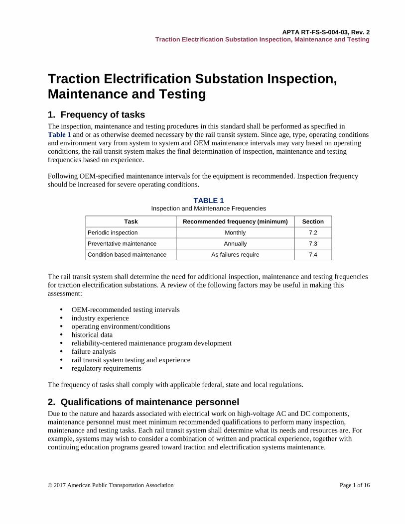
1. Frequency of tasks The inspection, maintenance and testing procedures in this standard shall be performed as specified in
Table 1 and or as otherwise deemed necessary by the rail transit system. Since age, type, operating conditions
and environment vary from system to system and OEM maintenance intervals may vary based on operating
conditions, the rail transit system makes the final determination of inspection, maintenance and testing
frequencies based on experience.
Following OEM-specified maintenance intervals for the equipment is recommended. Inspection frequency
should be increased for severe operating conditions.
TABLE 1 Inspection and Maintenance Frequencies
Task Recommended frequency (minimum) Section
Periodic inspection Monthly 7.2
Preventative maintenance Annually 7.3
Condition based maintenance As failures require 7.4
The rail transit system shall determine the need for additional inspection, maintenance and testing frequencies
for traction electrification substations. A review of the following factors may be useful in making this
assessment:
OEM-recommended testing intervals
industry experience
operating environment/conditions
historical data
reliability-centered maintenance program development
failure analysis
rail transit system testing and experience
regulatory requirements
The frequency of tasks shall comply with applicable federal, state and local regulations.
2. Qualifications of maintenance personnel Due to the nature and hazards associated with electrical work on high-voltage AC and DC components,
maintenance personnel must meet minimum recommended qualifications to perform many inspection,
maintenance and testing tasks. Each rail transit system shall determine what its needs and resources are. For
example, systems may wish to consider a combination of written and practical experience, together with
continuing education programs geared toward traction and electrification systems maintenance.
APTA RT-FS-S-004-03, Rev. 2 Traction Electrification Substation Inspection, Maintenance and Testing
© 2017 American Public Transportation Association Page 2 of 16
2.1 Skills and knowledge
Each rail transit system shall ensure that the employees and/or contractors who perform periodic inspection,
maintenance and testing have the knowledge and skills necessary to safely and effectively perform the tasks
assigned to them.
2.1.1 Basic inspection level
Inspectors must have a minimum of two years’ experience working with traction and electrification systems.
All inspectors must be familiar with the installation and repair of the components associated with traction and
electrification systems.
2.1.2 Maintenance level
Maintainers must have three or more years’ experience working on high-voltage power distribution or related
traction and electrification systems, either by in-house experience or recognized trade school or
apprenticeship training program.
2.1.3 Technician level
Technicians must have three or more years’ experience working on high voltage power distribution or related
traction and electrification systems or possess an associate in applied science (AAS) degree in electrical
systems or the equivalent.
2.2 Continuing education
A rail transit system should establish a continuing education program for the above positions based upon its
specific operation and requirements.
3. Tools The following tools are required for inspection, maintenance and testing of traction electrification substations:
torque wrench
multimeter*
megohmmeter*
standard tools carried by electrical maintenance workers
NOTE: Tools marked with an asterisk (*) must be calibrated in accordance with OEM and/or rail
transit system requirements.
4. Equipment lockout/tagout Proper lockout/tagout procedures shall be followed as required by the rail transit system.
5. Safety Rail transit system safety rules, procedures and practices shall be followed at all times during inspection,
maintenance and testing.
APTA RT-FS-S-004-03, Rev. 2 Traction Electrification Substation Inspection, Maintenance and Testing
© 2017 American Public Transportation Association Page 3 of 16
6. Personal protective equipment Personal protective equipment (PPE), as required by the rail transit system, shall be worn at all times during
inspection and testing.
Conductive personal articles shall not be worn when working on or about equipment.
Properly inspected and voltage-regulated insulating protective covers shall be used when working on or near
energized conductors and equipment. Insulating protective covers are to be used only for their designated
purpose.
7. Inspection, maintenance and testing Rail transit systems shall evaluate their local operating environment and conditions to develop or formally
adopt suitable inspection, maintenance and testing programs that include the following, as a minimum (where
applicable):
NOTE: Rail Transit Systems can supplement the minimum requirements below with applicable
Institute of Electrical and Electronics Engineers (IEEE) Standards.
7.1 Inspection, maintenance and testing categories
Periodic inspection and maintenance shall be performed to verify proper system operation and
general system upkeep.
Preventive maintenance (PM) and testing may require removing the equipment from service and
performing tests on the equipment or the materials to ensure proper operation. This type of
maintenance occurs on a regularly scheduled basis.
Condition-based maintenance shall be performed following a fault condition, an excessive number
of operations of equipment, or any abnormalities found.
7.2 Periodic inspection and maintenance
Monthly inspections and maintenance shall consist of the following:
a) Verify cleanliness of the substation site inside and outside. Particular attention should be given to
combustible rubbish material, such as newspapers, drawings and storage of materials not related to
substation operations and maintenance in the same room.
b) Check for the presence of oil, dust or other material generated from traction power equipment inside
or outside the equipment room or building.
c) Inspect and replace air filters.
d) Verify correct operation of any oil/water separators.
e) Check for presence of water or other material leaking into the substation from elsewhere.
f) Check for the presence of any “burning” smell, fumes, scorch marks or other material that could be
signs of a future breakdown.
g) Test emergency exit lighting and doors to verify that they meet all applicable codes.
h) Verify operation of all lamps. Replace as necessary.
i) Verify operation of all alarms.
j) Verify operation of heating and ventilation systems.
k) Verify that the DC switchgear enclosure is not energized except where applicable.
l) Verify that voltmeters/ammeters/wattmeters (and battery chargers and inverters if present) give
expected readings. Investigate any unexpected readings.
m) Record all counter readings where available.
APTA RT-FS-S-004-03, Rev. 2 Traction Electrification Substation Inspection, Maintenance and Testing
© 2017 American Public Transportation Association Page 4 of 16
7.3 Preventative maintenance and testing
Preventative maintenance shall include all items in Section 7.2 and Section 7.5.2 of this document.
7.4 Condition-based maintenance
7.4.1 Post-fault conditions
A post-fault condition is defined as any condition where a system failure occurred that has caused either
repetitive faults or lockout trip of any subsystem.
Example: A DC circuit short circuit would require a thorough check of the circuit breaker, distribution
system, ground and associated devices.
7.4.2 Other conditions
a) Exceeding the recommended number of operations under load conditions for circuit breakers.
b) Defects found during monthly inspections that would generate a priority 1 or 2 as listed in Section 9
of this standard.
c) Any abnormal conditions found.
7.5 Procedures
The rail transit system shall perform inspection, maintenance and testing in accordance with this standard and
develop local policies and procedures to meet the requirements herein.
No work shall be performed unless proper procedures, documentation and authorization have been obtained
from the rail transit system designated authority to perform the prescribed task at the designated location.
Upon completion of the work, the rail transit system designated authority must be informed that the
prescribed task is completed.
7.5.1 Written policies and procedures
Each rail transit system shall develop specific written policies and procedures that take into account specific
equipment designs and local operating conditions to implement the inspection, maintenance and testing
required by this standard. These policies and procedures shall give maintenance staff clear guidance and
criteria for performing these activities.
7.5.2 Procedures for inspecting, maintaining and testing substations
7.5.2.1 High-voltage equipment: AC vacuum breaker
Visual and mechanical inspection
a) Thoroughly clean the unit prior to testing.
b) Inspect the physical and mechanical condition.
c) Inspect anchorage, alignment and grounding.
d) Perform all mechanical operations tests on both the circuit breaker and its operating mechanism.
e) Verify the operation of heaters, if applicable.
f) Measure critical distances as recommended by the OEM. Make necessary adjustments.
g) Inspect bolted electrical connections using any one of the following methods:
• Verify tightness of accessible bolted electrical connections by calibrated torque-wrench
method in accordance with OEM recommendations. If a connection shows any sign of
corrosion, then the connection shall be cleaned or replaced.
• Perform a thermographic survey of equipment.

APTA RT-FS-S-004-03, Rev. 2 Traction Electrification Substation Inspection, Maintenance and Testing
© 2017 American Public Transportation Association Page 5 of 16
h) Verify appropriate contact lubrication per OEM recommendations on:
• moving current-carrying parts; and
• moving and sliding surfaces.
i) Record as-found and as-left operation counter readings.
Electrical tests
a) Perform a contact resistance test using a low-resistance ohmmeter capable of reading 2 μΩ. The
maximum reading is to be established by the rail transit system.
b) Verify trip, close, trip-free and anti-pump operations.
c) Trip the circuit breaker by operation of each of the protective devices.
d) Perform resistance measurements on bolted connections with a low-resistance ohmmeter.
e) Perform insulation-resistance tests pole-to-pole, pole-to-ground and across open poles in accordance
with the OEM manual.
f) Perform vacuum bottle integrity (over-potential) test across each vacuum bottle with the breaker in
the open positions in strict accordance with OEM published data. Do not exceed maximum voltage
stipulated for this test. Provide adequate barriers and protection against x-radiation during this test.
Do not perform this test unless the contact displacement of each interrupter is within OEM tolerance.
NOTE: Be aware that some DC high-potential test sets are half-wave rectified and may produce peak
voltages in excess of the breaker OEM-recommended maximum.
g) Perform insulation-resistance test at 1000 VDC on all control wiring. For units with solid-state
components, follow OEM recommendations.
Operation checks
a) Check each circuit breaker for proper operation. Perform the following checks as a minimum:
• Open and close the breaker via local control.
• Open and close the breaker via remote control (SCADA if applicable).
• Open and close the breaker while in the test position.
• Verify mechanical trip features where applicable.
b) For each operation check, verify the following (when applicable):
• Local breaker indication: Ensure that the indication lamps and any mechanical indications
function properly.
• Remote breaker indications: Ensure that the control center receives the proper indications
regarding breaker position if applicable (i.e., open/closed and remote/local condition).
Test values
a) Compare bolted connection resistance to values of similar connections.
b) Ensure bolt-torque levels are in accordance with OEM recommendations.
c) Ensure microhm or millivolt drop values do not exceed the high levels of the normal range as
indicated in the OEM published data. If the OEM data is not available, then investigate any values
that deviate from adjacent poles or similar breakers by more than 25 percent of the lowest value.
d) Ensure circuit breaker insulation resistance is in accordance with the OEM published data.
e) Contact displacement shall be in accordance with the factory-recorded data marked on the nameplate
of each vacuum breaker or bottle.
f) Ensure that the interrupter withstands the over-potential voltage applied.
g) Ensure that control wiring insulation resistance is a minimum of 2 MΩ.
h) Ensure that the insulation withstands the over-potential test voltage applied.
APTA RT-FS-S-004-03, Rev. 2 Traction Electrification Substation Inspection, Maintenance and Testing
© 2017 American Public Transportation Association Page 6 of 16
7.5.2.2 High-voltage equipment: AC switch
Visual and mechanical inspection
a) Inspect physical and mechanical condition.
b) Verify appropriate anchorage and required area clearances.
c) Verify appropriate equipment grounding.
d) Verify correct blade alignment, blade penetration, travel stops and mechanical operation.
e) Verify that fuse sizes and types (if applicable) are in accordance with the drawings.
f) Verify that expulsion-limiting devices are in place on all holders having expulsion-type elements.
g) Verify that each fuse holder (if applicable) has adequate mechanical support.
h) Inspect bolted electrical connections using one of the following methods:
• Verify tightness of accessible bolted electrical connections by calibrated torque-wrench
method in accordance with OEM published data.
• Perform a thermographic survey of the equipment.
i) Test all interlocking systems for correct operation and sequencing.
j) Inspect insulating assemblies for evidence of physical damage or contaminated surfaces.
k) Exercise all active components.
l) Compare switchblade clearances with OEM recommendations.
m) Verify all indicating and control devices for correct operation.
n) Verify operation of heaters, if applicable.
o) Verify appropriate contact lubrication per OEM recommendation on:
• current-carrying parts; and
• moving and sliding surfaces.
Electrical test
a) Perform insulation-resistance tests on each pole, phase-to-phase and phase-to-ground, with the switch
closed and across each open pole for 1 min. Test voltage shall be in accordance with OEM published
data.
b) Perform an over-potential test on each pole with the switch closed. Test each pole-to-ground with all
other poles grounded. Test voltage shall be in accordance with OEM published data.
c) Perform resistance measurements through each bolted connection with a low-resistance ohmmeter.
d) Perform a contact resistance test using a low-resistance ohmmeter capable of reading 2 μΩ.
Maximum reading to be established by the rail transit system.
e) Measure the fuse resistance, if applicable.
Test values
a) Compare bolted connection resistances to values of similar connections.
b) Ensure bolt-torque levels are as specified in OEM published data.
c) Ensure that microhm or millivolt drop values do not exceed the high levels of the normal range as
indicated in the OEM published data. If OEM data is not available, then investigate any values that
deviate from adjacent poles or similar switches by more than 25 percent of the lowest value.
d) Ensure that the insulation withstands the over-potential test voltage applied.
e) Ensure that insulation resistance is in accordance with the OEM published data.
f) Investigate fuse resistance values that deviate from each other by more than 15 percent.
APTA RT-FS-S-004-03, Rev. 2 Traction Electrification Substation Inspection, Maintenance and Testing
© 2017 American Public Transportation Association Page 7 of 16
7.5.2.3 Transformers: Dry type (VPI/cast coil)
Visual and mechanical inspection
a) Thoroughly clean the unit prior to testing.
b) Inspect physical, electrical and mechanical condition including evidence of moisture, corona or
brittleness.
c) Verify that control and alarm settings on temperature indicators are as specified.
d) Verify that cooling fans operate, where applicable.
e) Inspect all bolted electrical connections using one of the following methods:
• Verify tightness of accessible bolted electrical connections by calibrated torque-wrench
method in accordance with OEM published data.
• Perform thermographic survey.
f) Perform specific inspections and mechanical tests as recommended by the OEM.
g) Verify that the core, frame and enclosure are grounded.
h) While de-energized, operate any off-load or on-load tap changer through its complete range three
times.
i) Verify that as-left tap connections meet system requirements.
Electrical tests
a) Perform insulation-resistance tests winding-to-winding and each winding-to-ground; with the proper
test voltage (see References, ANSI/IEEE C57.12.91).
b) Perform resistance measurements through each bolted connection with a low-resistance ohmmeter.
c) Measure core insulation-resistance if the core is insulated and if the core ground strap is removable.
Test values
a) Compare bolted connection resistance to values of similar connections.
b) Ensure bolt-torque levels are in accordance with the OEM recommendations.
c) Ensure microhm or millivolt drop values do not exceed the high levels of the normal range as
indicated in the OEM published data. If the OEM data isn’t available, then investigate any values that
deviate from similar connections by more than 25 percent of the lowest value.
d) Ensure that insulation-resistance test values are no less than the values recommended in ANSI/IEEE
C57.12.91.
e) Ensure that core insulation resistance values are comparable to previously obtained results but not
less than 1 MΩ.
7.5.2.4 Transformers: Liquid filled
Visual and mechanical inspection
a) Inspect physical and mechanical condition.
b) Verify that control and alarm settings on temperature indicators are as specified.
c) Verify that cooling fans and/or pumps operate correctly.
d) Verify operation of all alarms, controls and trip circuits from temperature and level indicators,
pressure relief devices and fault pressure relays.
e) Inspect all bolted electrical connections using one of the following methods at a frequency of no more
than every five years:
• Verify tightness of accessible bolted electrical connections by calibrated torque-wrench
method in accordance with OEM published data.
• Perform thermographic survey.
f) Verify correct liquid level in all tanks and bushings.
g) Verify that positive pressure is maintained on nitrogen-blanketed transformers.
APTA RT-FS-S-004-03, Rev. 2 Traction Electrification Substation Inspection, Maintenance and Testing
© 2017 American Public Transportation Association Page 8 of 16
h) Verify that PCB concentration levels are visible.
i) While de-energized, operate any off-load or on-load tap changer through its complete range three
times.
j) Verify that as-left tap connections meet system requirements.
Electrical tests
a) Perform insulation-resistance tests winding-to-winding and each winding-to-ground; with the proper
test voltage (see References, ANSI/IEEEC57.12.90).
b) Perform resistance measurements through all bolted connections with a low-resistance ohmmeter.
c) Remove a sample of insulating liquid in accordance with ASTM D923. Samples should be sent to a
certified test facility for all required testing.
Test values
a) Compare bolted connection resistance to values of similar connections.
b) Ensure that bolt-torque levels are in accordance with the OEM recommendations.
c) Ensure that microhm or millivolt drop values do not exceed the high levels of the normal range as
indicated in the OEM published data. If the OEM data isn’t available, then investigate any values that
deviate from similar connections by more than 25 percent of the lowest value.
d) Ensure that insulation-resistance test values are no less than the values recommended in
ANSI/IEEEC57.12.90.
e) Investigate for the presence of dissolved gas in nitrogen gas blanket.
f) Evaluate and trend recommendations and test results from transformer liquid analysis.
7.5.2.5 Rectifiers
Visual and mechanical inspection
a) Thoroughly clean all apparatus and surrounding enclosure.
b) Inspect physical and mechanical connections.
c) Inspect anchorage and alignment.
d) Inspect all bolted connections and verify that bolt-torque values are consistent with OEM published
data.
e) Check fuse holders for adequate support.
f) Verify that fuse-blown indicators (where applicable) are properly mounted.
g) Inspect insulating assemblies for evidence of physical damage or contaminated surfaces.
h) Inspect all control wiring for integrity.
i) Test all electrical and mechanical interlocks for correct operation.
j) Replace filters (if applicable) when required.
7.5.2.6 Negative return switch
Visual and mechanical inspection
a) Thoroughly clean the unit prior to testing.
b) Inspect physical and mechanical condition.
c) Verify appropriate anchorage and required area clearances.
d) Verify correct blade alignment, blade penetration, travel stops and mechanical operation.
e) Inspect all bolted electrical connections using one of the following methods:
• Verify tightness of accessible bolted electrical connections by calibrated torque-wrench
method in accordance with OEM published data.
• Perform thermographic survey.
f) Test all interlocking systems for correct operation and sequencing.
APTA RT-FS-S-004-03, Rev. 2 Traction Electrification Substation Inspection, Maintenance and Testing
© 2017 American Public Transportation Association Page 9 of 16
g) Inspect insulating assemblies for evidence of physical damage or contaminated surfaces.
h) Exercise all active components.
i) Verify the correct operation of all indicating and control devices for correct operation.
j) Verify appropriate contact lubrication per OEM recommendation on:
• moving current-carrying parts; and
• moving and sliding surfaces.
Electrical test
a) Perform resistance measurements through all bolted connections with a low-resistance ohmmeter.
b) Measure contact resistance across each switchblade using a low-resistance ohmmeter capable of
reading 2 μΩ. Maximum reading to be established by the rail transit system.
Test values
a) Compare bolted connection resistances to values of similar connections.
b) Ensure that bolt-torque levels are as per OEM published data.
c) Ensure that microhm or millivolt drop values do not exceed the high levels of the normal range as
indicated in the OEM published data. If the OEM data is not available, then investigate any values
that deviate from adjacent poles or similar switches by more than 25 percent of the lowest value.
7.5.2.7 DC traction circuit breakers
Visual and mechanical inspection
a) Thoroughly clean the breaker prior to testing.
b) Inspect physical and mechanical condition.
c) Inspect anchorage and alignment.
d) Perform all mechanical operations tests on both the circuit breaker and its operating mechanism.
e) Verify operation of heaters, if applicable.
f) Measure critical distances such as contact gap as recommended by the OEM.
g) Inspect bolted electrical connections and verify tightness of accessible bolted electrical connections
by calibrated torque-wrench method in accordance with OEM recommendations. If connection shows
any signs of corrosion, then it shall be cleaned or replaced.
h) Verify appropriate contact lubrication per OEM recommendation on:
• moving current-carrying parts; and
• moving and sliding surfaces.
i) Record as-found and as-left operation counter readings.
j) Inspect all DC traction circuit breaker contacts. Contacts include but are not limited to:
• main contacts;
• arcing contacts;
• secondary contacts and/or disconnects; and
• auxiliary contacts.
k) Where applicable, check contacts for the following:
• Cleanliness: Ensure the contact surface is clean and kept free of any burrs and “spits.” Use
care if contacts are coated with silver or a silver alloy and when cleaning and/or deburring the
contact surface. To avoid damage to the contact surface, consult the OEM-recommended
procedure to determine the proper cleaning method.
• Wipe: Check contacts for proper wipe. Adhere to the OEM-recommended procedure for
checking contact wipe. Make necessary adjustments according to the OEM-recommended
practice.
APTA RT-FS-S-004-03, Rev. 2 Traction Electrification Substation Inspection, Maintenance and Testing
© 2017 American Public Transportation Association Page 10 of 16
• Pressure: Check contacts for proper pressure. Adhere to the OEM-recommended procedure
for checking contact pressure. Make necessary adjustments in accordance with the OEM-
recommended practice.
l) Clean arc chutes by performing the following tasks as a minimum:
• Inspect for any breakage to the inside sheet, arc plates or arc runner.
• Inspect the interrupting structure for the presence of foreign particles such as chips of
insulation and metal.
• Inspect the exterior of the arc chute for any damage or deformation to the outside sheets.
• Remove any foreign bodies or objects.
• Wipe the arc runner and arc horn with a dry cloth to remove dirt and dust accumulation.
• Wipe all insulated parts with a cloth saturated with an oil-free solvent to remove any oil
vapor film.
CAUTION: Use care when cleaning any arc chute. Some older arc chutes may contain asbestos
materials.
• Check to ensure that each puffer provides a moderate amount of air at the contact when the
breaker is opened. Use a suitable medium such as a piece of paper to detect air movement. If
the puffers do not show signs of puffing action, then do not place the breaker in service.
CAUTION: Care shall be exercised when performing this check. Keep clear of all moving parts to
avoid injury.
Electrical tests
a) Measure the contact resistance using a low-resistance ohmmeter capable of reading 2 μΩ. Maximum
reading to be established by the rail transit system.
b) Perform a contact-resistance test.
c) Verify trip, close, trip-free and anti-pump operations.
d) Trip the circuit breaker by operation of each of the protective devices.
e) Perform resistance measurements on each bolted connection with a low-resistance ohmmeter.
f) Perform insulation-resistance tests pole-to-pole, pole-to-ground and across open poles in accordance
with the OEM manual.
g) Perform an insulation-resistance test at 1000 VDC on all control wiring. For units with solid-state
components, follow the OEM recommendations.
Operation checks
a) Check each DC traction circuit breaker for proper operation. Check the following as a minimum:
• Open and close the breaker via local control.
• Open and close the breaker via remote control (SCADA if applicable).
• Open and close the breaker while in the test position.
• Verify mechanical trip features where applicable.
b) For each operation check, verify the following (when applicable):
• Local breaker indication: Ensure that the indication lamps and any mechanical indications
function properly.
• Remote breaker indications: Ensure that the control center receives the proper indications
regarding breaker position if applicable (i.e., open/closed and remote/local condition).
APTA RT-FS-S-004-03, Rev. 2 Traction Electrification Substation Inspection, Maintenance and Testing
© 2017 American Public Transportation Association Page 11 of 16
7.5.2.8 Batteries and chargers
Visual and mechanical inspection
a) Inspect physical and mechanical condition.
b) Inspect all bolted electrical connections using one of the following methods:
• Verify tightness of accessible bolted electrical connections by calibrated torque-wrench
method in accordance with OEM published data.
• Perform thermographic survey.
c) Clean corroded/oxidized terminals and apply an oxide inhibitor.
d) Verify proper electrolyte level (omit on sealed batteries).
e) Verify presence of flame arresters (omit on sealed batteries).
f) Verify adequacy of battery support racks, mounting, anchorage and clearances.
g) Verify the ventilation of battery room or enclosure.
h) Verify existence of suitable eyewash equipment.
Electrical tests
a) Perform resistance measurements through all bolted connections with a low-resistance ohmmeter
capable of reading 2 μΩ. Maximum reading to be established by the rail transit system.
b) Measure electrolyte specific gravity and temperature (omit on sealed batteries).
c) Measure charger float and equalizing voltage levels.
d) Verify all charger functions and alarms.
e) Measure each cell voltage and total battery voltage with charger energized and in float mode of
operation.
f) Verify operation of system equipment with power to the charger removed.
Test values
a) Compare bolted connection resistances to values of similar connections.
b) Ensure that bolt-torque levels are in accordance with OEM specifications.
c) Ensure that microhm or millivolt drop values do not exceed the high levels of the normal range as
indicated in the OEM published data. If the OEM data is not available, then investigate any values
that deviate from similar connections by more than 25 percent of the lowest value.
d) Ensure that charger float and equalize voltage levels are in accordance with the OEM published data.
e) Ensure that specific gravity is in accordance with the OEM-recommended values.
f) Ensure that electrolyte level is within normal limits.
g) Ensure than cell voltages are within 0.05 V of each other or in accordance with the OEM published
data.
7.5.2.9 Protective relays
Visual and mechanical inspection
a) Inspect physical and mechanical condition.
b) Inspect the relay contacts for burns, damage, misalignment, corrosion or other contamination.
c) Verify that settings are as intended.
Electrical tests
a) Perform OEM-recommended maintenance.
Test values
a) Ensure that test values are in accordance with OEM manuals.
APTA RT-FS-S-004-03, Rev. 2 Traction Electrification Substation Inspection, Maintenance and Testing
© 2017 American Public Transportation Association Page 12 of 16
8. Correction of deficiencies Deficiencies identified during inspection, maintenance and testing shall be corrected and documented in
accordance with OEM and/or rail transit system requirements. Some operational equipment may need to be
taken out of service immediately until the problem is corrected. Other equipment may be left in service and
corrected when parts, tools and/or appropriately skilled personnel are available.
The rail transit system shall designate a person responsible for deciding whether or not to leave defective
equipment in service in order to operate. In the absence of a designated person, the rail transit system shall
take the equipment out of service.
The rail transit system shall review and develop a corrective action plan for documented system defects
monthly.
9. Priority ratings The rail transit system shall develop a priority rating system to evaluate and determine the effects that any
single defect will have on the system if it chooses to operate with a known defect. Recommended priority
ratings are the following:
Priority 1: The defect will endanger the safety of patrons and personnel and/or continuation of
revenue service. A permanent or temporary repair shall be made immediately.
Priority 2: The defect may cause disruption of revenue service. The repair shall be made in a
predetermined timeframe set by each system.
Priority 3: The defect will not affect revenue service. The repair shall be made in a predetermined
timeframe set by each system.
10. Documentation The rail transit system shall develop and implement a fully auditable process for recording and tracking
inspection, maintenance and testing activities and outstanding system defects. Such documentation shall be
documented, reviewed and filed in accordance with rail transit system procedures and OEM
recommendations. Documentation should be kept for the life of all in-service equipment.
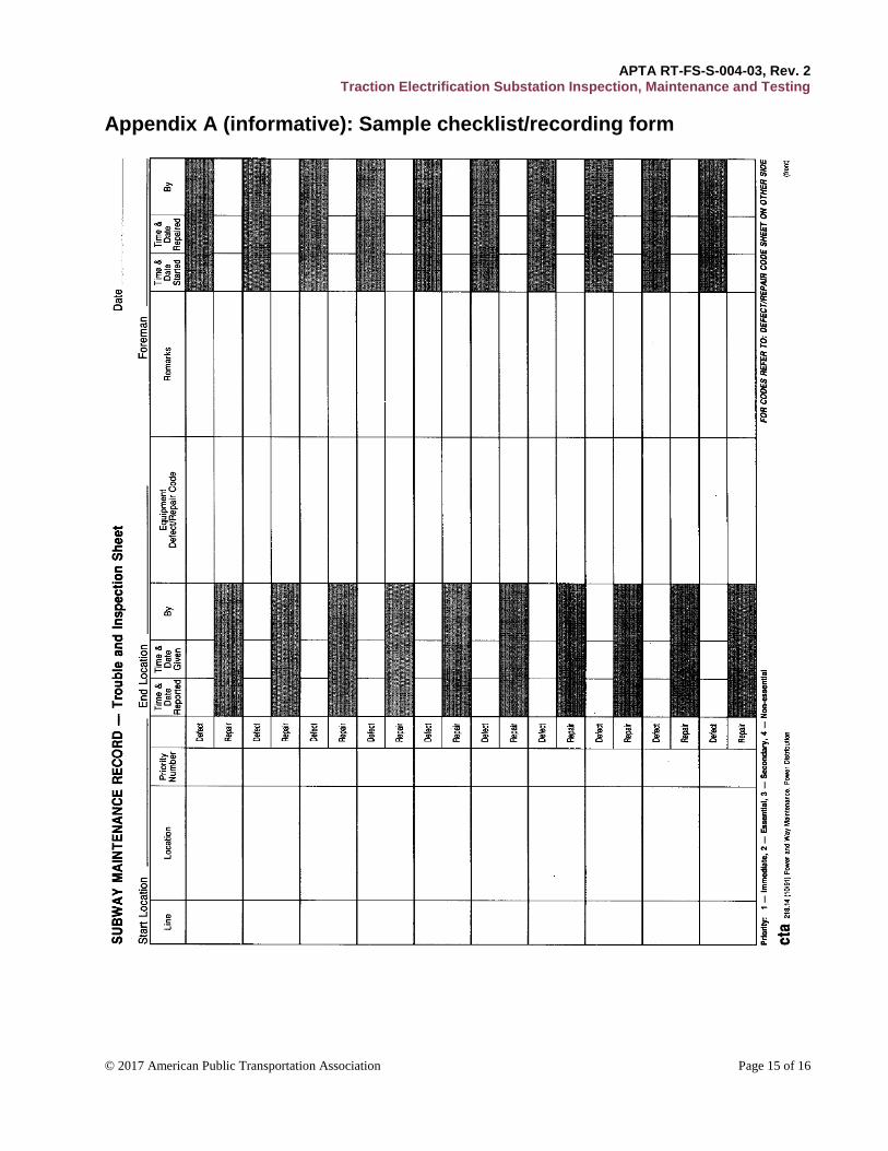
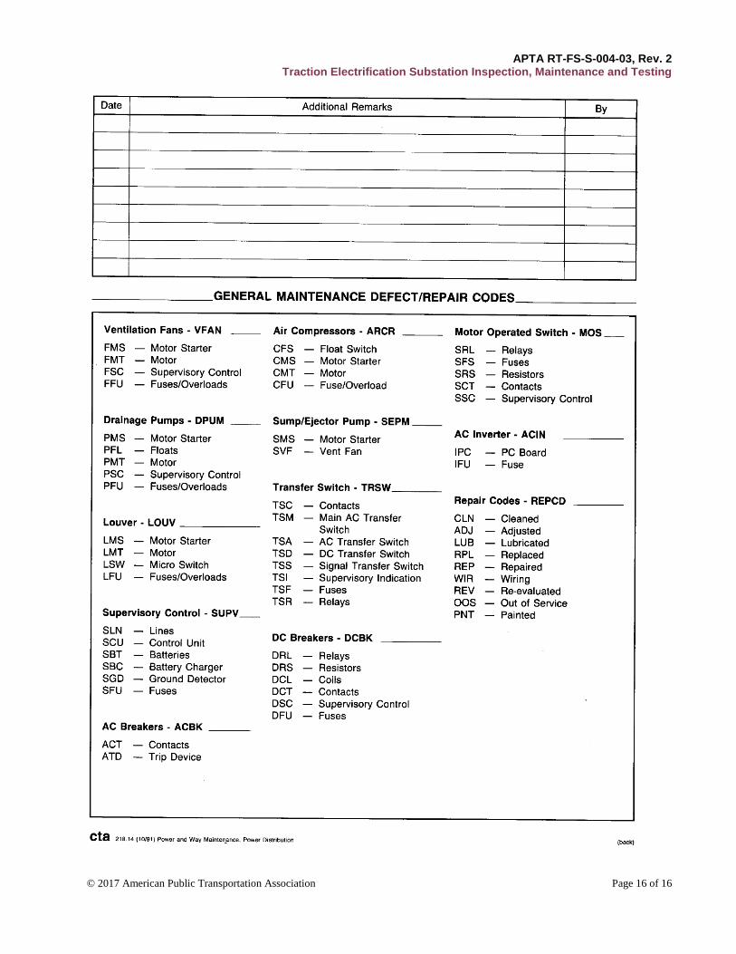
Annex A contains a sample checklist and recording form that rail transit systems can adapt to their specific
equipment and operating environment.
APTA RT-FS-S-004-03, Rev. 2 Traction Electrification Substation Inspection, Maintenance and Testing
© 2017 American Public Transportation Association Page 13 of 16
References
This document shall be used in conjunction with the most recent version of the following publications:
American National Standards Institute:
ANSI/IEEE C57.12.90 (2010 or most current), Standard Test Code for Liquid Immersed Distribution
Power and Regulating Transformers and Guide for Short Circuit Testing of Distribution and Power
Transformers.
ANSI/IEEE C57.12.91 (2011 or most current), Test Code for Dry Type Distribution and Power
Transformers.
NFPA 70E, Standard for Electrical Safety Requirements.
Definitions
arc: An electrical spark that occurs when current jumps across an air gap as a result of a number of
conditions. Arcing is a common electrical hazard.
conductive personal article: A personal item that can conduct electricity. Examples of conductive personal
articles are metal watch bands, metal-framed safety glasses, finger rings, jewelry, metal belt buckles, hearing
aids with external wiring, etc.
contractor: Any individual or entity under contract with the rail transit system (including rail transit system
and subcontractor personnel) to install, inspect, maintain and/or test vehicles, systems and components. Also
called a consultant.
heavy rail system: An electric railway capable of a heavy volume of traffic characterized by exclusive
rights-of-way, multicar trains, high speeds, rapid acceleration, sophisticated signaling and high-platform
passenger loading. Also called elevated railway, rapid rail, rapid transit or subway.
light rail system: An electric railway with a lighter volume of train traffic than heavy rail that may use
shared or exclusive rights-of-way and may run trains intermingled with street traffic. Light rail systems
frequently operate with low platform loading and single car trains. Also called streetcars, trams or trolley cars.
original equipment manufacturer (OEM): The enterprise that initially designs and builds a piece of
equipment.
personal protective equipment (PPE): All clothing and other work accessories designed to create a barrier
against workplace hazards. Examples include safety goggles, blast shields, hard hats, hearing protectors,
gloves, respirators, aprons and work boots.
post-fault condition: Any condition caused by a system failure that causes either repetitive faults or lockout
trip of any subsystem.
rail transit system: The organization or portion of an organization that operates rail transit service and
related activities. Also called an operating agency, operating authority, transit agency, transit authority or
transit system.
APTA RT-FS-S-004-03, Rev. 2 Traction Electrification Substation Inspection, Maintenance and Testing
© 2017 American Public Transportation Association Page 14 of 16
Abbreviations and acronyms
μΩ microhms
AAS associate in applied science
AC alternating current
ANSI American National Standards Institute
DC direct current
IEEE Institute of Electrical and Electronic Engineers
MΩ megohms NATSA North American Transit Services Association
NFPA National Fire Protection Agency
OEM original equipment manufacturer
PCB polychlorinated biphenyls
PPE personal protective equipment
PM preventive maintenance
SCADA supervisory control and data acquisition system
V volts
VDC volts direct current
VPI vacuum pressure impregnated
Summary of document changes
Document formatted to the new APTA standard format.
Sections have been moved and renumbered.
Scope and summary moved to the front page.
Sections of definitions, abbreviations and acronyms moved to the rear of the document.
Two new sections added: “Summary of document changes” and “Document history.”
Some global changes to section headings and numberings resulted when sections dealing with
references and acronyms were moved to the end of the document, along with other cosmetic changes,
such as capitalization, punctuation, spelling, grammar and general flow of text.
Section 7; Language added to allow Agencies to also incorporate IEEE standards into their
inspection, maintenance and testing procedures.
Section 7: Removed IEEE standard dates from the text body.
Updated References; Modified ANSI/IEEE C57.12.90 to (2010 or most current) and ANSI/IEEE
C57.12.91 to (2011 or most current) to allow the use of the specified year or the most current as they
become adopted by IEEE.
Minor editorial changes.
Document history
Document Version
Working Group Vote
Public Comment/ Technical Oversight
Rail CEO Approval
Rail Policy & Planning Approval
Publish Date
First published June 25, 2002 — — Sept. 28, 2003 September 2003
First revision — — — — July 26, 2004
Second Revision June 14, 2017 August 1, 2017 Sept. 18, 2017 November 2, 2017 December 6, 2017
APTA RT-FS-S-004-03, Rev. 2 Traction Electrification Substation Inspection, Maintenance and Testing
© 2017 American Public Transportation Association Page 15 of 16
Appendix A (informative): Sample checklist/recording form
APTA RT-FS-S-004-03, Rev. 2 Traction Electrification Substation Inspection, Maintenance and Testing
© 2017 American Public Transportation Association Page 16 of 16