the yuen long section: viaducts and stations - soundsorb rail yuen lo… · the arup journal 3/2006...
TRANSCRIPT
The Arup Journal 3/2006 7
Introduction
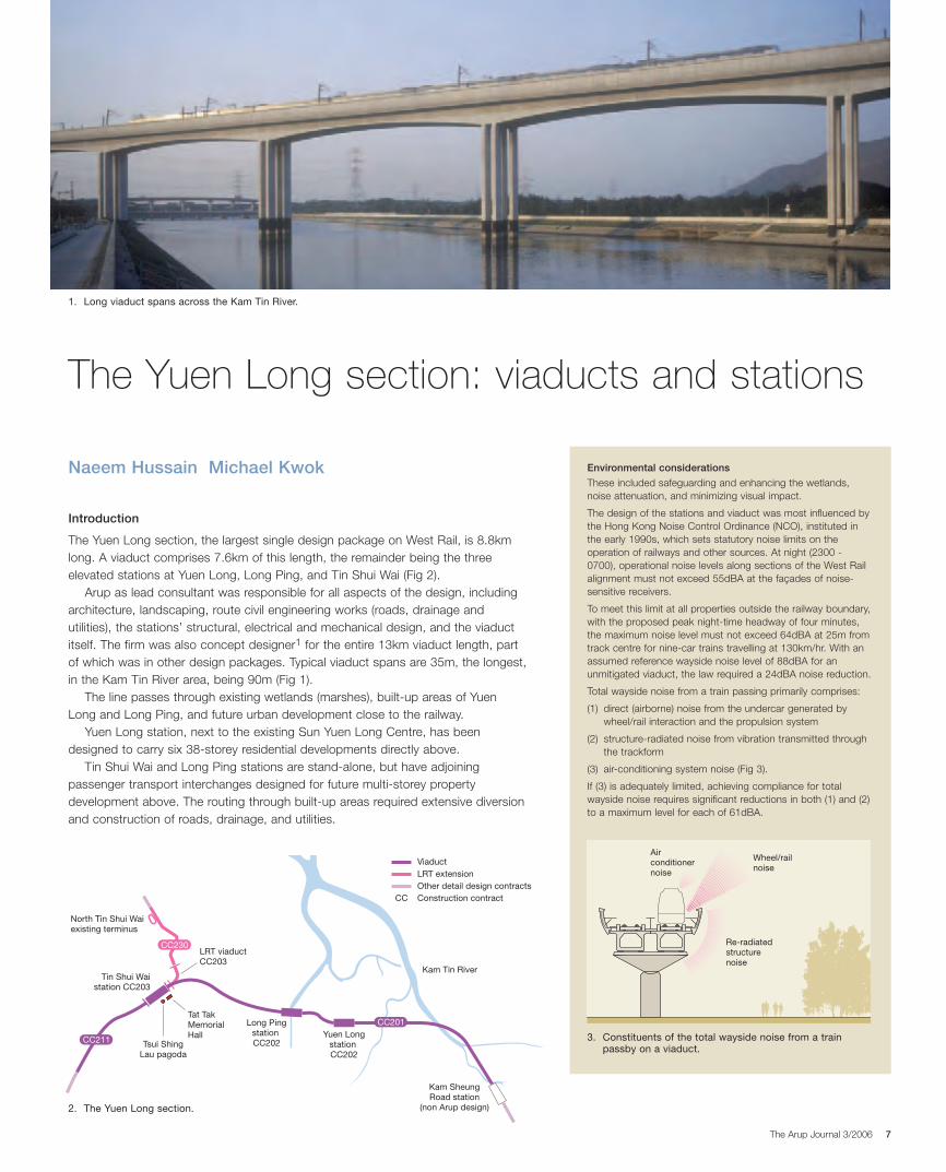
The Yuen Long section, the largest single design package on West Rail, is 8.8kmlong. A viaduct comprises 7.6km of this length, the remainder being the threeelevated stations at Yuen Long, Long Ping, and Tin Shui Wai (Fig 2).
Arup as lead consultant was responsible for all aspects of the design, includingarchitecture, landscaping, route civil engineering works (roads, drainage andutilities), the stations’ structural, electrical and mechanical design, and the viaductitself. The firm was also concept designer1 for the entire 13km viaduct length, partof which was in other design packages. Typical viaduct spans are 35m, the longest,in the Kam Tin River area, being 90m (Fig 1).
The line passes through existing wetlands (marshes), built-up areas of YuenLong and Long Ping, and future urban development close to the railway.
Yuen Long station, next to the existing Sun Yuen Long Centre, has beendesigned to carry six 38-storey residential developments directly above.
Tin Shui Wai and Long Ping stations are stand-alone, but have adjoiningpassenger transport interchanges designed for future multi-storey propertydevelopment above. The routing through built-up areas required extensive diversionand construction of roads, drainage, and utilities.
The Yuen Long section: viaducts and stations
Naeem Hussain Michael Kwok
Kam SheungRoad station
(non Arup design)
Yuen LongstationCC202
Long PingstationCC202
LRT viaductCC203
Tin Shui Waistation CC203
Tat TakMemorialHall
Tsui ShingLau pagoda
North Tin Shui Waiexisting terminus
ViaductLRT extensionOther detail design contractsConstruction contractCC
Kam Tin River
CC211
CC201
CC230
Environmental considerations
These included safeguarding and enhancing the wetlands,noise attenuation, and minimizing visual impact.
The design of the stations and viaduct was most influenced bythe Hong Kong Noise Control Ordinance (NCO), instituted inthe early 1990s, which sets statutory noise limits on theoperation of railways and other sources. At night (2300 -0700), operational noise levels along sections of the West Railalignment must not exceed 55dBA at the façades of noise-sensitive receivers.
To meet this limit at all properties outside the railway boundary,with the proposed peak night-time headway of four minutes,the maximum noise level must not exceed 64dBA at 25m fromtrack centre for nine-car trains travelling at 130km/hr. With anassumed reference wayside noise level of 88dBA for anunmitigated viaduct, the law required a 24dBA noise reduction.
Total wayside noise from a train passing primarily comprises:
(1) direct (airborne) noise from the undercar generated bywheel/rail interaction and the propulsion system
(2) structure-radiated noise from vibration transmitted throughthe trackform
(3) air-conditioning system noise (Fig 3).
If (3) is adequately limited, achieving compliance for totalwayside noise requires significant reductions in both (1) and (2)to a maximum level for each of 61dBA.
Wheel/railnoise
Re-radiatedstructurenoise
Airconditionernoise
3. Constituents of the total wayside noise from a trainpassby on a viaduct.
2. The Yuen Long section.
1. Long viaduct spans across the Kam Tin River.
16033_Arup.qxd 1/12/06 7:53 pm Page 7
The Arup Journal 3/20068
ViaductsAttenuation of airborne noise
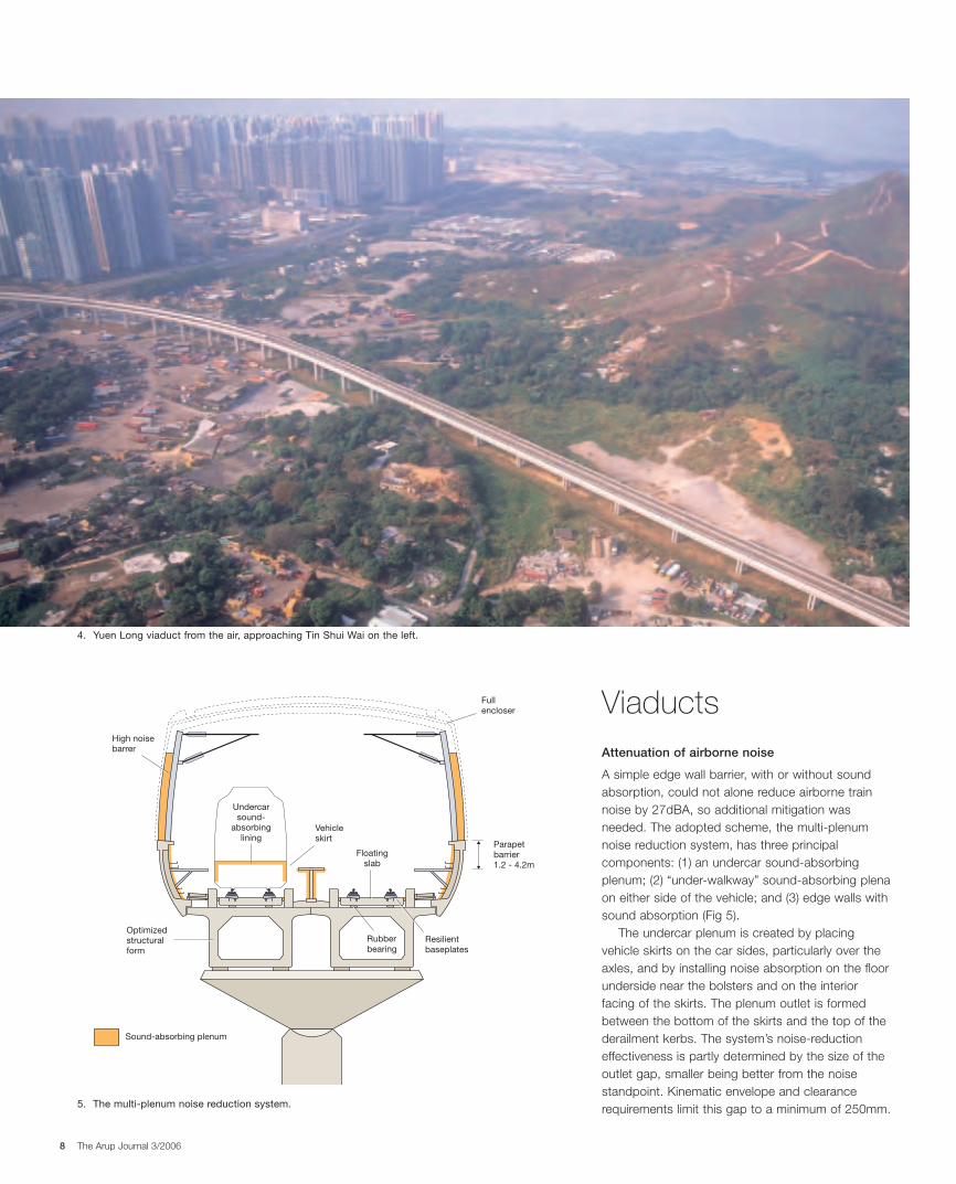
A simple edge wall barrier, with or without soundabsorption, could not alone reduce airborne trainnoise by 27dBA, so additional mitigation wasneeded. The adopted scheme, the multi-plenumnoise reduction system, has three principalcomponents: (1) an undercar sound-absorbingplenum; (2) “under-walkway” sound-absorbing plenaon either side of the vehicle; and (3) edge walls withsound absorption (Fig 5).
The undercar plenum is created by placingvehicle skirts on the car sides, particularly over theaxles, and by installing noise absorption on the floorunderside near the bolsters and on the interiorfacing of the skirts. The plenum outlet is formedbetween the bottom of the skirts and the top of thederailment kerbs. The system’s noise-reductioneffectiveness is partly determined by the size of theoutlet gap, smaller being better from the noisestandpoint. Kinematic envelope and clearancerequirements limit this gap to a minimum of 250mm.
Fullencloser
High noisebarrer
Undercarsound-
absorbinglining
Vehicleskirt
Sound-absorbing plenum
Resilientbaseplates
Floatingslab
Rubberbearing
Optimizedstructuralform
Parapetbarrier1.2 - 4.2m
5. The multi-plenum noise reduction system.
4. Yuen Long viaduct from the air, approaching Tin Shui Wai on the left.
16033_Arup.qxd 1/12/06 7:53 pm Page 8
The Arup Journal 3/2006 9
The under-walkway plenum on the viaduct wayside is bounded by the parapet,the deck, the walkway, and the vehicle. Sound absorption is placed on the edgewall and the walkway underside. The plenum outlet is the gap between thewalkway and the vehicle, again limited by the vehicle kinematic and curvatureenvelopes. For West Rail, the minimum gap size is 250mm on straight track and350-400mm on curves. Derailment safety requires that the vehicle can movelaterally by roughly 600mm during derailment, implying that the walkway must befriable and minimize impact load to prevent damage to or detachment of theconcrete parapet from the deck. The under-walkway plenum at the viaduct centre isbounded by a median wall, the deck, the top plate, and the vehicle. Because ofviaduct width limitations, this plenum has less volume than those under the edgewalkways, and so is not as effective in attenuating noise.
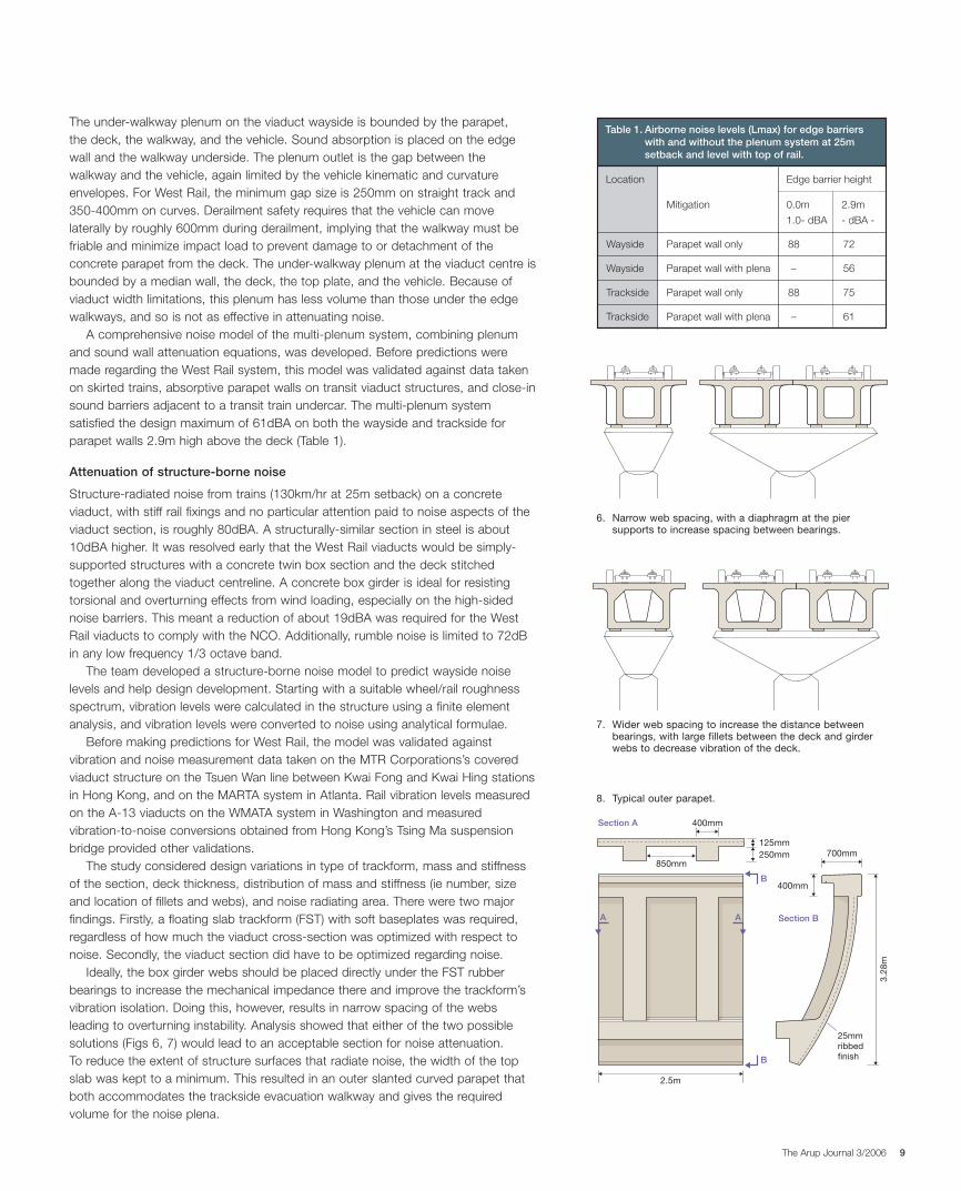
A comprehensive noise model of the multi-plenum system, combining plenumand sound wall attenuation equations, was developed. Before predictions weremade regarding the West Rail system, this model was validated against data takenon skirted trains, absorptive parapet walls on transit viaduct structures, and close-insound barriers adjacent to a transit train undercar. The multi-plenum systemsatisfied the design maximum of 61dBA on both the wayside and trackside forparapet walls 2.9m high above the deck (Table 1).
Attenuation of structure-borne noise
Structure-radiated noise from trains (130km/hr at 25m setback) on a concreteviaduct, with stiff rail fixings and no particular attention paid to noise aspects of theviaduct section, is roughly 80dBA. A structurally-similar section in steel is about10dBA higher. It was resolved early that the West Rail viaducts would be simply-supported structures with a concrete twin box section and the deck stitchedtogether along the viaduct centreline. A concrete box girder is ideal for resistingtorsional and overturning effects from wind loading, especially on the high-sidednoise barriers. This meant a reduction of about 19dBA was required for the WestRail viaducts to comply with the NCO. Additionally, rumble noise is limited to 72dBin any low frequency 1/3 octave band.
The team developed a structure-borne noise model to predict wayside noiselevels and help design development. Starting with a suitable wheel/rail roughnessspectrum, vibration levels were calculated in the structure using a finite elementanalysis, and vibration levels were converted to noise using analytical formulae.
Before making predictions for West Rail, the model was validated againstvibration and noise measurement data taken on the MTR Corporations’s coveredviaduct structure on the Tsuen Wan line between Kwai Fong and Kwai Hing stationsin Hong Kong, and on the MARTA system in Atlanta. Rail vibration levels measuredon the A-13 viaducts on the WMATA system in Washington and measuredvibration-to-noise conversions obtained from Hong Kong’s Tsing Ma suspensionbridge provided other validations.
The study considered design variations in type of trackform, mass and stiffnessof the section, deck thickness, distribution of mass and stiffness (ie number, sizeand location of fillets and webs), and noise radiating area. There were two majorfindings. Firstly, a floating slab trackform (FST) with soft baseplates was required,regardless of how much the viaduct cross-section was optimized with respect tonoise. Secondly, the viaduct section did have to be optimized regarding noise.
Ideally, the box girder webs should be placed directly under the FST rubberbearings to increase the mechanical impedance there and improve the trackform’svibration isolation. Doing this, however, results in narrow spacing of the websleading to overturning instability. Analysis showed that either of the two possiblesolutions (Figs 6, 7) would lead to an acceptable section for noise attenuation.To reduce the extent of structure surfaces that radiate noise, the width of the topslab was kept to a minimum. This resulted in an outer slanted curved parapet thatboth accommodates the trackside evacuation walkway and gives the requiredvolume for the noise plena.
Table 1. Airborne noise levels (Lmax) for edge barrierswith and without the plenum system at 25msetback and level with top of rail.
Location
Mitigation 0.0m 2.9m
1.0- dBA - dBA -
Edge barrier height
Wayside Parapet wall only 88 72
Wayside Parapet wall with plena – 56
Trackside Parapet wall only 88 75
Trackside Parapet wall with plena – 61
8. Typical outer parapet.
7. Wider web spacing to increase the distance betweenbearings, with large fillets between the deck and girderwebs to decrease vibration of the deck.
6. Narrow web spacing, with a diaphragm at the piersupports to increase spacing between bearings.
250mm
400mm
3.28
m400mm
125mm
850mm
2.5m
700mm
A
Section A
Section B
B
B
A
25mmribbedfinish
16033_Arup.qxd 1/12/06 7:53 pm Page 9
The Arup Journal 3/200610
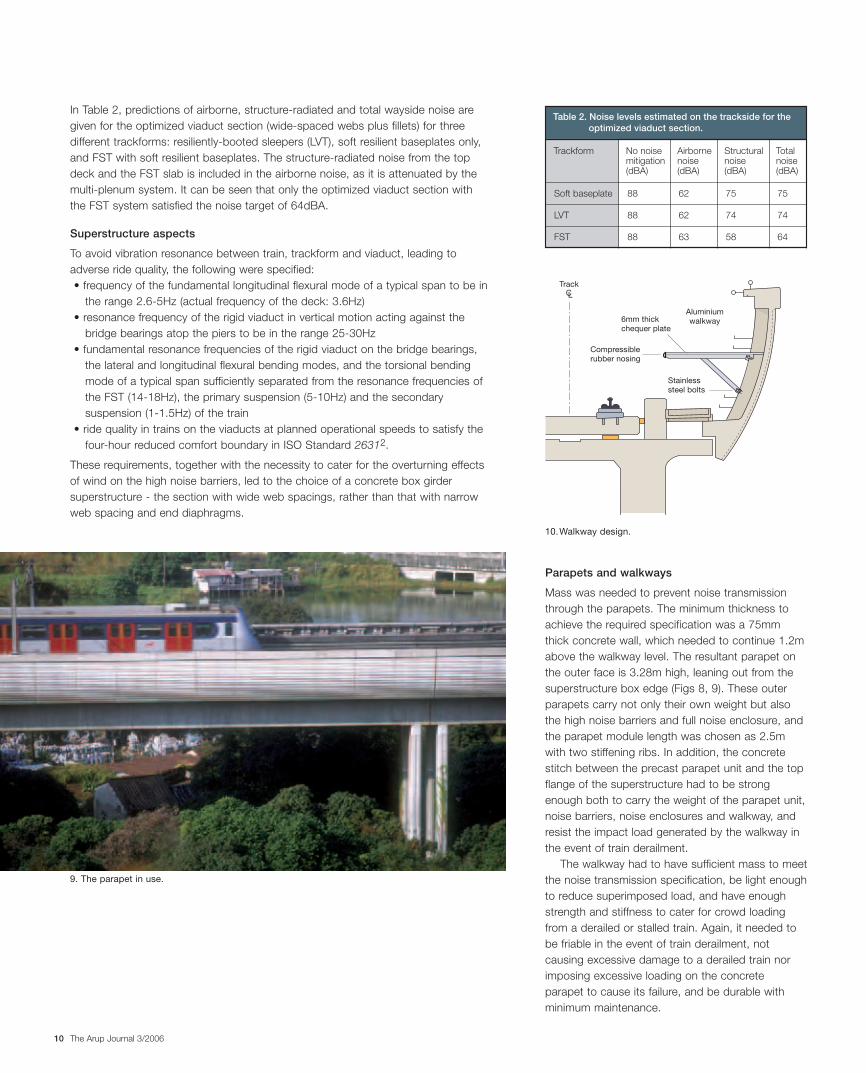
In Table 2, predictions of airborne, structure-radiated and total wayside noise aregiven for the optimized viaduct section (wide-spaced webs plus fillets) for threedifferent trackforms: resiliently-booted sleepers (LVT), soft resilient baseplates only,and FST with soft resilient baseplates. The structure-radiated noise from the topdeck and the FST slab is included in the airborne noise, as it is attenuated by themulti-plenum system. It can be seen that only the optimized viaduct section withthe FST system satisfied the noise target of 64dBA.
Superstructure aspects
To avoid vibration resonance between train, trackform and viaduct, leading toadverse ride quality, the following were specified:• frequency of the fundamental longitudinal flexural mode of a typical span to be in
the range 2.6-5Hz (actual frequency of the deck: 3.6Hz)• resonance frequency of the rigid viaduct in vertical motion acting against the
bridge bearings atop the piers to be in the range 25-30Hz• fundamental resonance frequencies of the rigid viaduct on the bridge bearings,
the lateral and longitudinal flexural bending modes, and the torsional bendingmode of a typical span sufficiently separated from the resonance frequencies ofthe FST (14-18Hz), the primary suspension (5-10Hz) and the secondarysuspension (1-1.5Hz) of the train
• ride quality in trains on the viaducts at planned operational speeds to satisfy thefour-hour reduced comfort boundary in ISO Standard 26312.
These requirements, together with the necessity to cater for the overturning effectsof wind on the high noise barriers, led to the choice of a concrete box girdersuperstructure - the section with wide web spacings, rather than that with narrowweb spacing and end diaphragms.
Parapets and walkways
Mass was needed to prevent noise transmissionthrough the parapets. The minimum thickness toachieve the required specification was a 75mmthick concrete wall, which needed to continue 1.2mabove the walkway level. The resultant parapet onthe outer face is 3.28m high, leaning out from thesuperstructure box edge (Figs 8, 9). These outerparapets carry not only their own weight but alsothe high noise barriers and full noise enclosure, andthe parapet module length was chosen as 2.5mwith two stiffening ribs. In addition, the concretestitch between the precast parapet unit and the topflange of the superstructure had to be strongenough both to carry the weight of the parapet unit,noise barriers, noise enclosures and walkway, andresist the impact load generated by the walkway inthe event of train derailment.
The walkway had to have sufficient mass to meetthe noise transmission specification, be light enoughto reduce superimposed load, and have enoughstrength and stiffness to cater for crowd loadingfrom a derailed or stalled train. Again, it needed tobe friable in the event of train derailment, notcausing excessive damage to a derailed train norimposing excessive loading on the concreteparapet to cause its failure, and be durable withminimum maintenance.
9. The parapet in use.
CTrack
Aluminiumwalkway
Compressiblerubber nosing
Stainlesssteel bolts
6mm thickchequer plate
Table 2. Noise levels estimated on the trackside for theoptimized viaduct section.
Trackform No noisemitigation(dBA)
Airbornenoise(dBA)
Structuralnoise(dBA)
Totalnoise(dBA)
Soft baseplate 88
LVT 88
FST 88
62
62
63
75
74
58
75
74
64
10.Walkway design.
16033_Arup.qxd 1/12/06 7:53 pm Page 10
The Arup Journal 3/2006 11
These conflicting requirements led to the choice of 6mm thick aluminium platessupported on an aluminium frame (Fig 10). The horizontal load on the concreteparapet, from in-plane buckling of the aluminium plate caused by a derailing train,had to be minimized, and realtime dynamic analysis on the Arup program DYNA3showed that three overlapping plates, rather than a single one, were required toreduce the generated force so that it did not cause a catastrophic failure of theconcrete stitch connecting the outer parapet to the superstructure.
Noise barriers and full noise enclosure
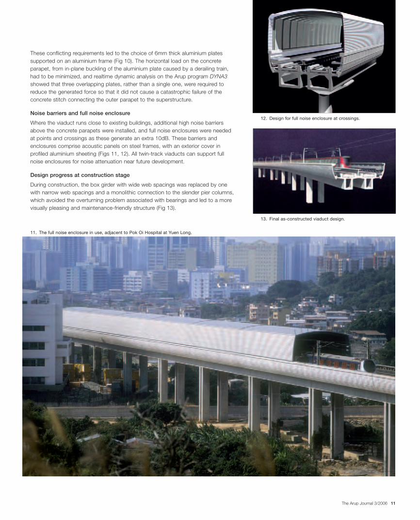
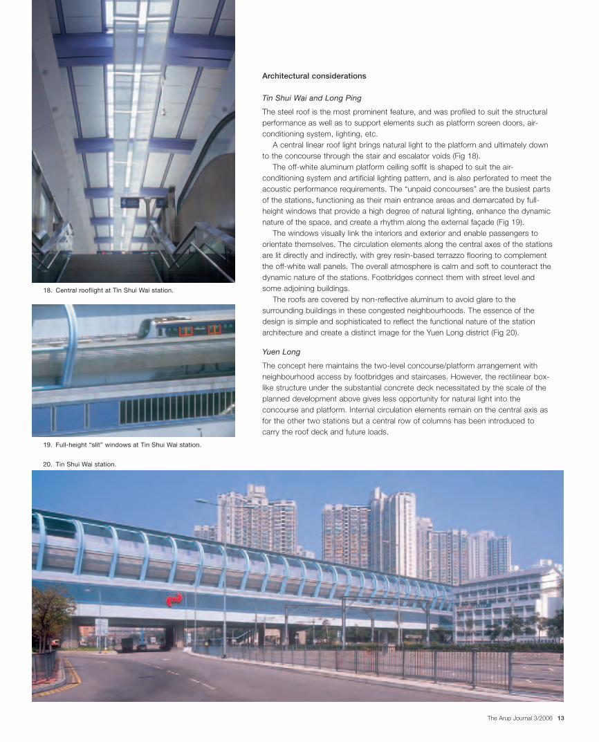
Where the viaduct runs close to existing buildings, additional high noise barriersabove the concrete parapets were installed, and full noise enclosures were neededat points and crossings as these generate an extra 10dB. These barriers andenclosures comprise acoustic panels on steel frames, with an exterior cover inprofiled aluminium sheeting (Figs 11, 12). All twin-track viaducts can support fullnoise enclosures for noise attenuation near future development.
Design progress at construction stage
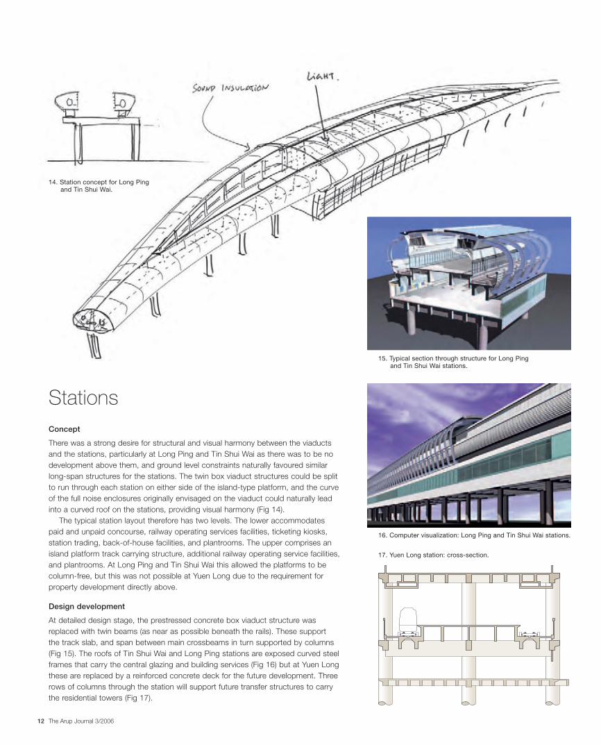
During construction, the box girder with wide web spacings was replaced by onewith narrow web spacings and a monolithic connection to the slender pier columns,which avoided the overturning problem associated with bearings and led to a morevisually pleasing and maintenance-friendly structure (Fig 13).
11. The full noise enclosure in use, adjacent to Pok Oi Hospital at Yuen Long.
13. Final as-constructed viaduct design.
12. Design for full noise enclosure at crossings.
16033_Arup.qxd 1/12/06 7:53 pm Page 11
The Arup Journal 3/200612
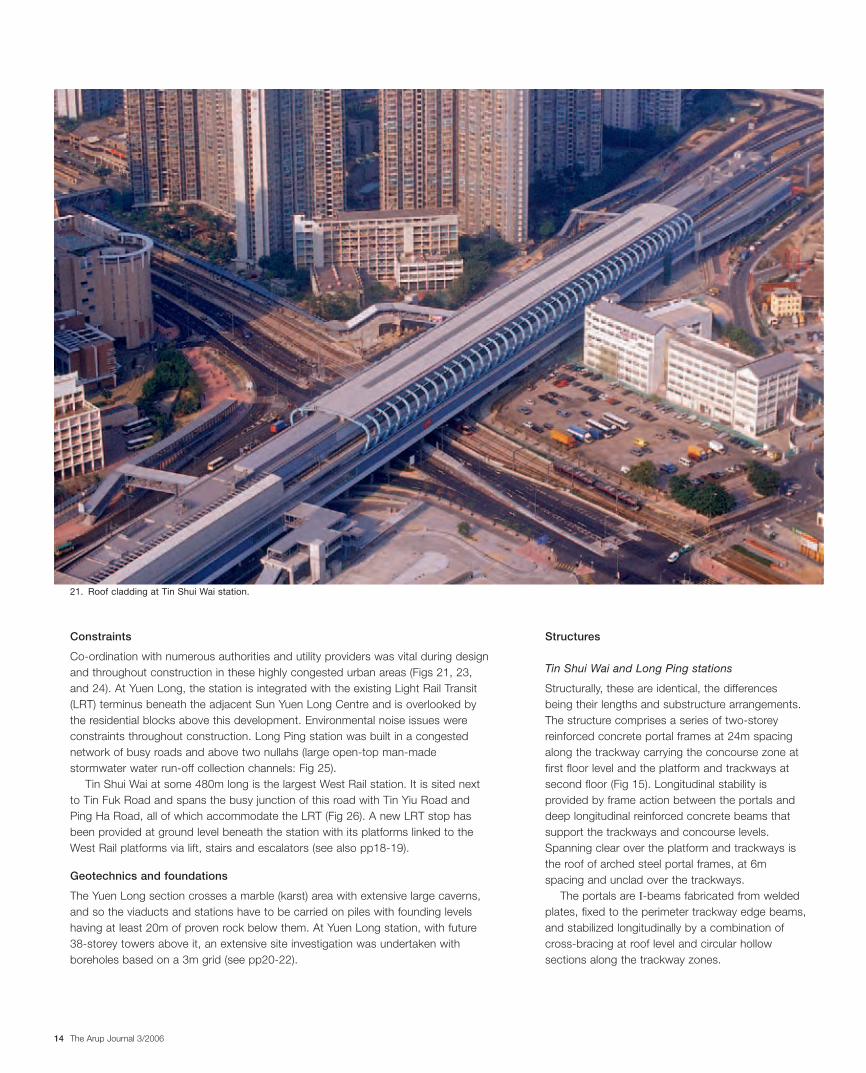
StationsConcept
There was a strong desire for structural and visual harmony between the viaductsand the stations, particularly at Long Ping and Tin Shui Wai as there was to be nodevelopment above them, and ground level constraints naturally favoured similarlong-span structures for the stations. The twin box viaduct structures could be splitto run through each station on either side of the island-type platform, and the curveof the full noise enclosures originally envisaged on the viaduct could naturally leadinto a curved roof on the stations, providing visual harmony (Fig 14).
The typical station layout therefore has two levels. The lower accommodatespaid and unpaid concourse, railway operating services facilities, ticketing kiosks,station trading, back-of-house facilities, and plantrooms. The upper comprises anisland platform track carrying structure, additional railway operating service facilities,and plantrooms. At Long Ping and Tin Shui Wai this allowed the platforms to becolumn-free, but this was not possible at Yuen Long due to the requirement forproperty development directly above.
Design development
At detailed design stage, the prestressed concrete box viaduct structure wasreplaced with twin beams (as near as possible beneath the rails). These supportthe track slab, and span between main crossbeams in turn supported by columns(Fig 15). The roofs of Tin Shui Wai and Long Ping stations are exposed curved steelframes that carry the central glazing and building services (Fig 16) but at Yuen Longthese are replaced by a reinforced concrete deck for the future development. Threerows of columns through the station will support future transfer structures to carrythe residential towers (Fig 17).
15. Typical section through structure for Long Pingand Tin Shui Wai stations.
14. Station concept for Long Pingand Tin Shui Wai.
16. Computer visualization: Long Ping and Tin Shui Wai stations.
17. Yuen Long station: cross-section.
16033_Arup.qxd 1/12/06 7:53 pm Page 12
The Arup Journal 3/2006 13
Architectural considerations
Tin Shui Wai and Long Ping
The steel roof is the most prominent feature, and was profiled to suit the structuralperformance as well as to support elements such as platform screen doors, air-conditioning system, lighting, etc.
A central linear roof light brings natural light to the platform and ultimately downto the concourse through the stair and escalator voids (Fig 18).
The off-white aluminum platform ceiling soffit is shaped to suit the air-conditioning system and artificial lighting pattern, and is also perforated to meet theacoustic performance requirements. The “unpaid concourses” are the busiest partsof the stations, functioning as their main entrance areas and demarcated by full-height windows that provide a high degree of natural lighting, enhance the dynamicnature of the space, and create a rhythm along the external façade (Fig 19).
The windows visually link the interiors and exterior and enable passengers toorientate themselves. The circulation elements along the central axes of the stationsare lit directly and indirectly, with grey resin-based terrazzo flooring to complementthe off-white wall panels. The overall atmosphere is calm and soft to counteract thedynamic nature of the stations. Footbridges connect them with street level andsome adjoining buildings.
The roofs are covered by non-reflective aluminum to avoid glare to thesurrounding buildings in these congested neighbourhoods. The essence of thedesign is simple and sophisticated to reflect the functional nature of the stationarchitecture and create a distinct image for the Yuen Long district (Fig 20).
Yuen Long
The concept here maintains the two-level concourse/platform arrangement withneighbourhood access by footbridges and staircases. However, the rectilinear box-like structure under the substantial concrete deck necessitated by the scale of theplanned development above gives less opportunity for natural light into theconcourse and platform. Internal circulation elements remain on the central axis asfor the other two stations but a central row of columns has been introduced tocarry the roof deck and future loads.
20. Tin Shui Wai station.
19. Full-height “slit” windows at Tin Shui Wai station.
18. Central rooflight at Tin Shui Wai station.
16033_Arup.qxd 1/12/06 7:53 pm Page 13
The Arup Journal 3/200614
Constraints
Co-ordination with numerous authorities and utility providers was vital during designand throughout construction in these highly congested urban areas (Figs 21, 23,and 24). At Yuen Long, the station is integrated with the existing Light Rail Transit(LRT) terminus beneath the adjacent Sun Yuen Long Centre and is overlooked bythe residential blocks above this development. Environmental noise issues wereconstraints throughout construction. Long Ping station was built in a congestednetwork of busy roads and above two nullahs (large open-top man-madestormwater water run-off collection channels: Fig 25).
Tin Shui Wai at some 480m long is the largest West Rail station. It is sited nextto Tin Fuk Road and spans the busy junction of this road with Tin Yiu Road andPing Ha Road, all of which accommodate the LRT (Fig 26). A new LRT stop hasbeen provided at ground level beneath the station with its platforms linked to theWest Rail platforms via lift, stairs and escalators (see also pp18-19).
Geotechnics and foundations
The Yuen Long section crosses a marble (karst) area with extensive large caverns,and so the viaducts and stations have to be carried on piles with founding levelshaving at least 20m of proven rock below them. At Yuen Long station, with future38-storey towers above it, an extensive site investigation was undertaken withboreholes based on a 3m grid (see pp20-22).
Structures
Tin Shui Wai and Long Ping stations
Structurally, these are identical, the differencesbeing their lengths and substructure arrangements.The structure comprises a series of two-storeyreinforced concrete portal frames at 24m spacingalong the trackway carrying the concourse zone atfirst floor level and the platform and trackways atsecond floor (Fig 15). Longitudinal stability isprovided by frame action between the portals anddeep longitudinal reinforced concrete beams thatsupport the trackways and concourse levels.Spanning clear over the platform and trackways isthe roof of arched steel portal frames, at 6mspacing and unclad over the trackways.
The portals are I-beams fabricated from weldedplates, fixed to the perimeter trackway edge beams,and stabilized longitudinally by a combination ofcross-bracing at roof level and circular hollowsections along the trackway zones.
21. Roof cladding at Tin Shui Wai station.
16033_Arup.qxd 1/12/06 7:53 pm Page 14
The Arup Journal 3/2006 15
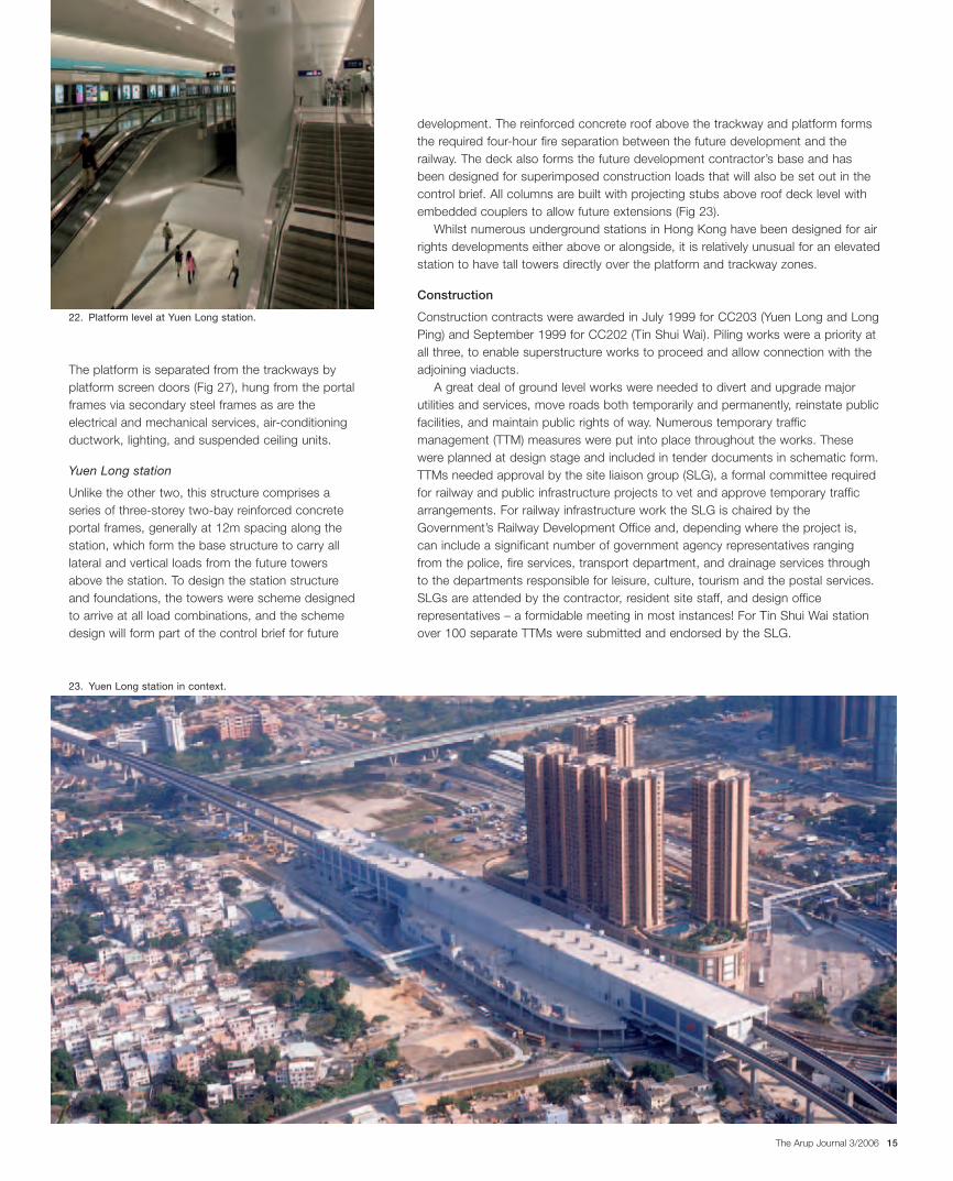
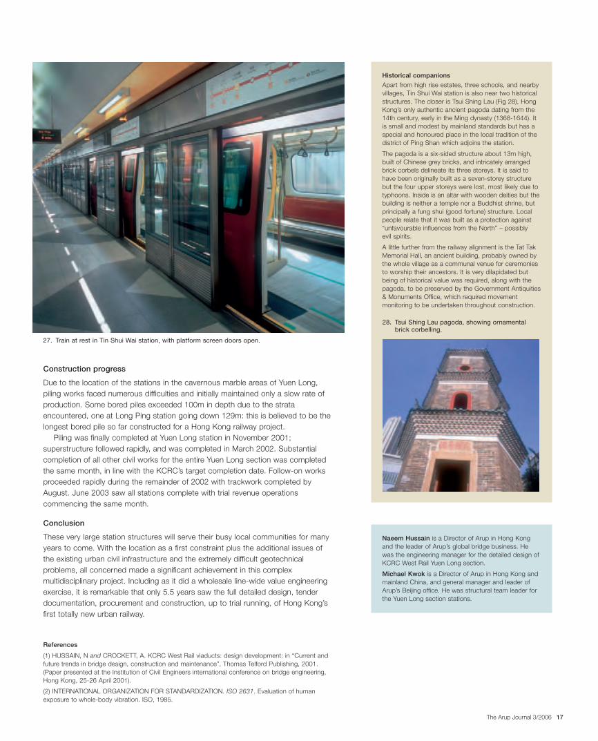
The platform is separated from the trackways byplatform screen doors (Fig 27), hung from the portalframes via secondary steel frames as are theelectrical and mechanical services, air-conditioningductwork, lighting, and suspended ceiling units.
Yuen Long station
Unlike the other two, this structure comprises aseries of three-storey two-bay reinforced concreteportal frames, generally at 12m spacing along thestation, which form the base structure to carry alllateral and vertical loads from the future towersabove the station. To design the station structureand foundations, the towers were scheme designedto arrive at all load combinations, and the schemedesign will form part of the control brief for future
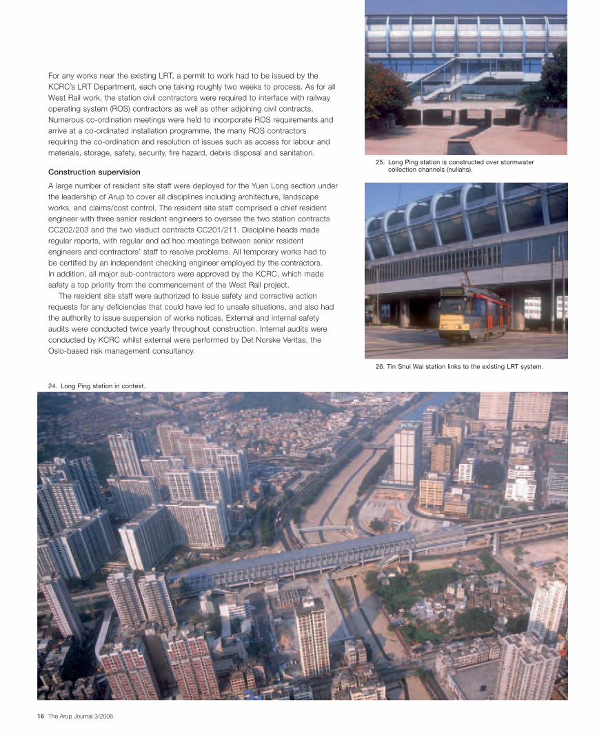
development. The reinforced concrete roof above the trackway and platform formsthe required four-hour fire separation between the future development and therailway. The deck also forms the future development contractor’s base and hasbeen designed for superimposed construction loads that will also be set out in thecontrol brief. All columns are built with projecting stubs above roof deck level withembedded couplers to allow future extensions (Fig 23).
Whilst numerous underground stations in Hong Kong have been designed for airrights developments either above or alongside, it is relatively unusual for an elevatedstation to have tall towers directly over the platform and trackway zones.
Construction
Construction contracts were awarded in July 1999 for CC203 (Yuen Long and LongPing) and September 1999 for CC202 (Tin Shui Wai). Piling works were a priority atall three, to enable superstructure works to proceed and allow connection with theadjoining viaducts.
A great deal of ground level works were needed to divert and upgrade majorutilities and services, move roads both temporarily and permanently, reinstate publicfacilities, and maintain public rights of way. Numerous temporary trafficmanagement (TTM) measures were put into place throughout the works. Thesewere planned at design stage and included in tender documents in schematic form.TTMs needed approval by the site liaison group (SLG), a formal committee requiredfor railway and public infrastructure projects to vet and approve temporary trafficarrangements. For railway infrastructure work the SLG is chaired by theGovernment’s Railway Development Office and, depending where the project is,can include a significant number of government agency representatives rangingfrom the police, fire services, transport department, and drainage services throughto the departments responsible for leisure, culture, tourism and the postal services.SLGs are attended by the contractor, resident site staff, and design officerepresentatives – a formidable meeting in most instances! For Tin Shui Wai stationover 100 separate TTMs were submitted and endorsed by the SLG.
23. Yuen Long station in context.
22. Platform level at Yuen Long station.
16033_Arup.qxd 1/12/06 7:53 pm Page 15
The Arup Journal 3/200616
For any works near the existing LRT, a permit to work had to be issued by theKCRC’s LRT Department, each one taking roughly two weeks to process. As for allWest Rail work, the station civil contractors were required to interface with railwayoperating system (ROS) contractors as well as other adjoining civil contracts.Numerous co-ordination meetings were held to incorporate ROS requirements andarrive at a co-ordinated installation programme, the many ROS contractorsrequiring the co-ordination and resolution of issues such as access for labour andmaterials, storage, safety, security, fire hazard, debris disposal and sanitation.
Construction supervision
A large number of resident site staff were deployed for the Yuen Long section underthe leadership of Arup to cover all disciplines including architecture, landscapeworks, and claims/cost control. The resident site staff comprised a chief residentengineer with three senior resident engineers to oversee the two station contractsCC202/203 and the two viaduct contracts CC201/211. Discipline heads maderegular reports, with regular and ad hoc meetings between senior residentengineers and contractors’ staff to resolve problems. All temporary works had to be certified by an independent checking engineer employed by the contractors. In addition, all major sub-contractors were approved by the KCRC, which madesafety a top priority from the commencement of the West Rail project.
The resident site staff were authorized to issue safety and corrective actionrequests for any deficiencies that could have led to unsafe situations, and also hadthe authority to issue suspension of works notices. External and internal safetyaudits were conducted twice yearly throughout construction. Internal audits wereconducted by KCRC whilst external were performed by Det Norske Veritas, theOslo-based risk management consultancy.
26. Tin Shui Wai station links to the existing LRT system.
25. Long Ping station is constructed over stormwatercollection channels (nullahs).
24. Long Ping station in context.
16033_Arup.qxd 1/12/06 7:53 pm Page 16
The Arup Journal 3/2006 17
Naeem Hussain is a Director of Arup in Hong Kongand the leader of Arup’s global bridge business. Hewas the engineering manager for the detailed design ofKCRC West Rail Yuen Long section.
Michael Kwok is a Director of Arup in Hong Kong andmainland China, and general manager and leader ofArup’s Beijing office. He was structural team leader forthe Yuen Long section stations.
Historical companions
Apart from high rise estates, three schools, and nearbyvillages, Tin Shui Wai station is also near two historicalstructures. The closer is Tsui Shing Lau (Fig 28), HongKong’s only authentic ancient pagoda dating from the14th century, early in the Ming dynasty (1368-1644). Itis small and modest by mainland standards but has aspecial and honoured place in the local tradition of thedistrict of Ping Shan which adjoins the station.
The pagoda is a six-sided structure about 13m high,built of Chinese grey bricks, and intricately arrangedbrick corbels delineate its three storeys. It is said tohave been originally built as a seven-storey structurebut the four upper storeys were lost, most likely due totyphoons. Inside is an altar with wooden deities but thebuilding is neither a temple nor a Buddhist shrine, butprincipally a fung shui (good fortune) structure. Localpeople relate that it was built as a protection against“unfavourable influences from the North” – possibly evil spirits.
A little further from the railway alignment is the Tat TakMemorial Hall, an ancient building, probably owned bythe whole village as a communal venue for ceremoniesto worship their ancestors. It is very dilapidated butbeing of historical value was required, along with thepagoda, to be preserved by the Government Antiquities& Monuments Office, which required movementmonitoring to be undertaken throughout construction.
Construction progress
Due to the location of the stations in the cavernous marble areas of Yuen Long,piling works faced numerous difficulties and initially maintained only a slow rate ofproduction. Some bored piles exceeded 100m in depth due to the strataencountered, one at Long Ping station going down 129m: this is believed to be thelongest bored pile so far constructed for a Hong Kong railway project.
Piling was finally completed at Yuen Long station in November 2001;superstructure followed rapidly, and was completed in March 2002. Substantialcompletion of all other civil works for the entire Yuen Long section was completedthe same month, in line with the KCRC’s target completion date. Follow-on worksproceeded rapidly during the remainder of 2002 with trackwork completed byAugust. June 2003 saw all stations complete with trial revenue operationscommencing the same month.
Conclusion
These very large station structures will serve their busy local communities for manyyears to come. With the location as a first constraint plus the additional issues ofthe existing urban civil infrastructure and the extremely difficult geotechnicalproblems, all concerned made a significant achievement in this complexmultidisciplinary project. Including as it did a wholesale line-wide value engineeringexercise, it is remarkable that only 5.5 years saw the full detailed design, tenderdocumentation, procurement and construction, up to trial running, of Hong Kong’sfirst totally new urban railway.
References
(1) HUSSAIN, N and CROCKETT, A. KCRC West Rail viaducts: design development: in “Current andfuture trends in bridge design, construction and maintenance”, Thomas Telford Publishing, 2001.(Paper presented at the Institution of Civil Engineers international conference on bridge engineering,Hong Kong, 25-26 April 2001).
(2) INTERNATIONAL ORGANIZATION FOR STANDARDIZATION. ISO 2631. Evaluation of humanexposure to whole-body vibration. ISO, 1985.
28. Tsui Shing Lau pagoda, showing ornamentalbrick corbelling.
27. Train at rest in Tin Shui Wai station, with platform screen doors open.
16033_Arup.qxd 1/12/06 7:53 pm Page 17