study of hybrid active power filter for power …ethesis.nitrkl.ac.in/5920/1/e-91.pdf · study of...
TRANSCRIPT
STUDY OF HYBRID ACTIVE POWER
FILTER FOR POWER QUALITY
IMPROVEMENT
A THESIS SUBMITTED IN PARTIAL FULFILLMENT
OF THE REQUIREMENTS FOR THE DEGREE OF
Master of Technology
In
Power Electronics and Drives By
Azmera Sandeep (ROLL NO: 212EE4254)
DEPARTMENT OF ELECTRICAL ENGINEERING
NATIONAL INSTITUTE OF TECHNOLOGY
ROURKELA-769008, INDIA.
2012-2014
STUDY OF HYBRID ACTIVE POWER
FILTER FOR POWER QUALITY
IMPROVEMENT
A THESIS SUBMITTED IN PARTIAL
FULFILLMENT OF THE REQUIREMENTS FOR
THE DEGREE OF
Master of Technology
In
Power Electronics and Drives By
Azmera sandeep Under the Guidance of
Prof. Prafulla Chandra Panda
DEPARTMENT OF ELECTRICAL ENGINEERING
NATIONAL INSTITUTE OF TECHNOLOGY
ROURKELA-769008, INDIA

DEPARTMENT OF ELECTRICAL ENGINEERING
NATIONAL INSTITUTE OF TECHNOLOGY
ROURKELA
ORISSA, INDIA-769008
CERTIFICATE
This is to certify that the thesis entitled “Study Of Hybrid Active Power Filter For
Power Quality Improvement”, submitted by Mr. Azmera Sandeep in partial fulfillment of
the requirements for the award of Master of Technology in Electrical Engineering with
specialization in “Power Electronics and Drives” at National Institute of Technology,
Rourkela. A bona fide record of research work carried out by him under my supervision and
guidance. The candidate has fulfilled all the prescribed requirements. The Thesis which is
based on candidates own work, has not submitted elsewhere for a degree/diploma.
In my opinion, the thesis is of standard required for the award of a master of technology
Degree in Electrical Engineering.
Place: Rourkela
Date:
Prof. P. C. Panda Dept. of Electrical Engg.
National Institute of Technology
Rourkela – 769008

ACKNOWLEDGEMENTS
I would like to articulate my profound gratitude and indebtedness to my
supervisor Prof. P.C. Panda, from whom I learnt not only academic skills but
life skills too, for his constant motivation, support, expert guidance, constant
supervision and constructive suggestion for the submission of my progress report
of thesis work.
I express my sincere gratitude to Prof. A.K. Panda, Head of the Department,
Electrical Engineering for invaluable suggestions and constant encouragement all
through the research work.
I would also like to acknowledge the entire teaching and non-teaching staff of
Electrical department for establishing a working environment and for constructive
discussions.
The discussions held with research scholars of power electronics and drives branch, is
worth to Mention especially with Sowjanya, Sandeep kumar, Nagarjuna, that made
my study at NIT, Rourkela most fruitful and enjoyable.
Finally, I am always indebted to all my family members, especially my parents for
their endless support and love.
Azmera Sandeep
Roll-no :-212EE4254
Dept. of Electrical Engg.
National Institute of Technology
Rourkela – 769008

Dedicated To
My beloved Parents
i
CONTENTS
ABSTRACT……………………………………………………………………………iii
List Figures……………………………………………………………………………...iv
List of Tables…………………………………………………………………………....vi
CHAPTER 1
INTRODUCTION……………………………………………………………………….1
1.1 Introduction……………………………………………………………………..2
1.2 Literature review………………………………………………………………..2
1.3 Research motivation………………………………………………………….…4
1.3.1 Power quality problems…………………………………………………..4
1.3.2 Solutions to power quality problems……………………………………..4
1.3.3 Advantages of hybrid power filter………………………………………..5
1.4 Thesis objectives……………………………………………………....................5
1.5 Organization of thesis………………………………………………..…………..6
CHAPTER 2
TYPES OF FILTERS………………………………………………………………….7
2.1 Introduction………………………………………………………………….8
2.2 Filter classification…………………………………………………………..8
2.2.1 Passive Power Filters………………………………………………..9
2.2.2 Active Power Filters (APF)………………………………………..10
2.2.3 Hybrid Power Filters……………………………………………….13
2.3 Chapter summary…………………………………………………………...16
CHAPTER 3
CONTROL OF HYBRID POWER FILTER FOR POWER QUALITY
IMPROVEMENT……………………………………………………………………17
3.1 Introduction………………………………………………………………..18
3.2 Design of series active power filter………………………………………..18
3.3 Modeling of series active power filter……………………………………..19
ii
3.4 Control strategy………………………………..………………………….21
3.4.1 Compensation Strategy……………………………………………..22
3.4.2 Reference Vector Generation…………………………….................24
3.5 Chapter summary………………………………………………………....25
CHAPTER 4
SIMULATION RESULTS AND DISCUSSIONS…………………………..........26
4.1 Introduction…………………………………………………………….....27
4.2 Simulation results with balanced load………………………………….....27
4.2.1 With the Actual System Parameters…………………………….…..28
4.2.2 When the Source Impedance is changed………………………..…..33
4.2.3 When the DC Load Resistance Value is Changed………………... .35
4.2.4 Comparative Study under Balanced Load Condition………………38
4.3 Simulation results with unbalanced load…………………………………38
4.3.1 With the Actual System Parameters…………………………….....39
4.3.2 When the Source Impedance is Changed……………………….....41
4.3.3 Comparative Study under Unbalanced Load Condition…………..42
4.4 Chapter summary………………………………………………………...43
CHAPTER 5
CONCLUSION AND SCOPE FOR FUTURE WORK…………………………….44
5.1 Conclusion…………………………………………………………………45
5.2 Future Scope…………………………………………………………...…..46
References…………………………………………………………………………..47
Publication…………………………………………………………………………..49
iii
ABSTRACT
Now-a-days with the advancement of technology, the demand for electric power is
increasing at an exponential rate. Many consumer appliances demand quality power
continuously for their operation. The performance of the end user equipment is heavily
dependent on the quality of power supplied to it. But the quality of power delivered to
the end user is affected by various external and internal factors. They are like voltage and
frequency variations, faults, outages etc.
These power quality problems reduce the life time and efficiency of the equipment.
Thus, to enhance the performance of the consumer equipment and also the overall
performance of the system these problems should be mitigated.
The main affect caused by these problems is the presence of harmonics. This leads to the
overheating of the equipment, insulation failure and over speeding of induction motors
etc. The solution to overcome these problems is to filter out these harmonics. For this
purpose there are many filters topologies present in the literature.
In this project a hybrid filter which is a combination of series active filter and shunt
passive filter is studied. This project presents the control strategy to control the filter in
such a way that the harmonics are reduced. The proposed control strategy is simulated in
MATLAB SIMULINK and the results are presented.
iv
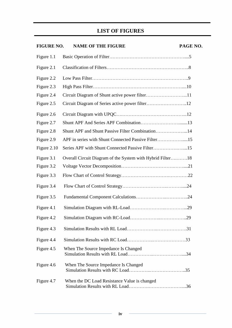
LIST OF FIGURES FIGURE NO. NAME OF THE FIGURE PAGE NO.
Figure 1.1 Basic Operation of Filter…………………………………………....5
Figure 2.1 Classification of Filters……………………………………………..8
Figure 2.2 Low Pass Filter……………………………………………………..9 Figure 2.3 High Pass Filter…………………………………………………....10 Figure 2.4 Circuit Diagram of Shunt active power filter……………………...11 Figure 2.5 Circuit Diagram of Series active power filter……………………..12
Figure 2.6 Circuit Diagram with UPQC….…………………………………...12 Figure 2.7 Shunt APF And Series APF Combination……………………........13 Figure 2.8 Shunt APF and Shunt Passive Filter Combination………………...14 Figure 2.9 APF in series with Shunt Connected Passive Filter……………......15 Figure 2.10 Series APF with Shunt Connected Passive Filter…………….…....15
Figure 3.1 Overall Circuit Diagram of the System with Hybrid Filter….…….18
Figure 3.2 Voltage Vector Decomposition…………………………….……....21
Figure 3.3 Flow Chart of Control Strategy………………………….…………22
Figure 3.4 Flow Chart of Control Strategy………………………..……….....24
Figure 3.5 Fundamental Component Calculations………………..…………..24
Figure 4.1 Simulation Diagram with RL-Load…………………..…………...29
Figure 4.2 Simulation Diagram with RC-Load………………..……………..29
Figure 4.3 Simulation Results with RL Load………………..……………….31
Figure 4.4 Simulation Results with RC Load……………..…………………33
Figure 4.5 When The Source Impedance Is Changed
Simulation Results with RL Load……………..………………....34
Figure 4.6 When The Source Impedance Is Changed
Simulation Results with RC Load…………..…………………..35
Figure 4.7 When the DC Load Resistance Value is changed
Simulation Results with RL Load………….…………………....36
v
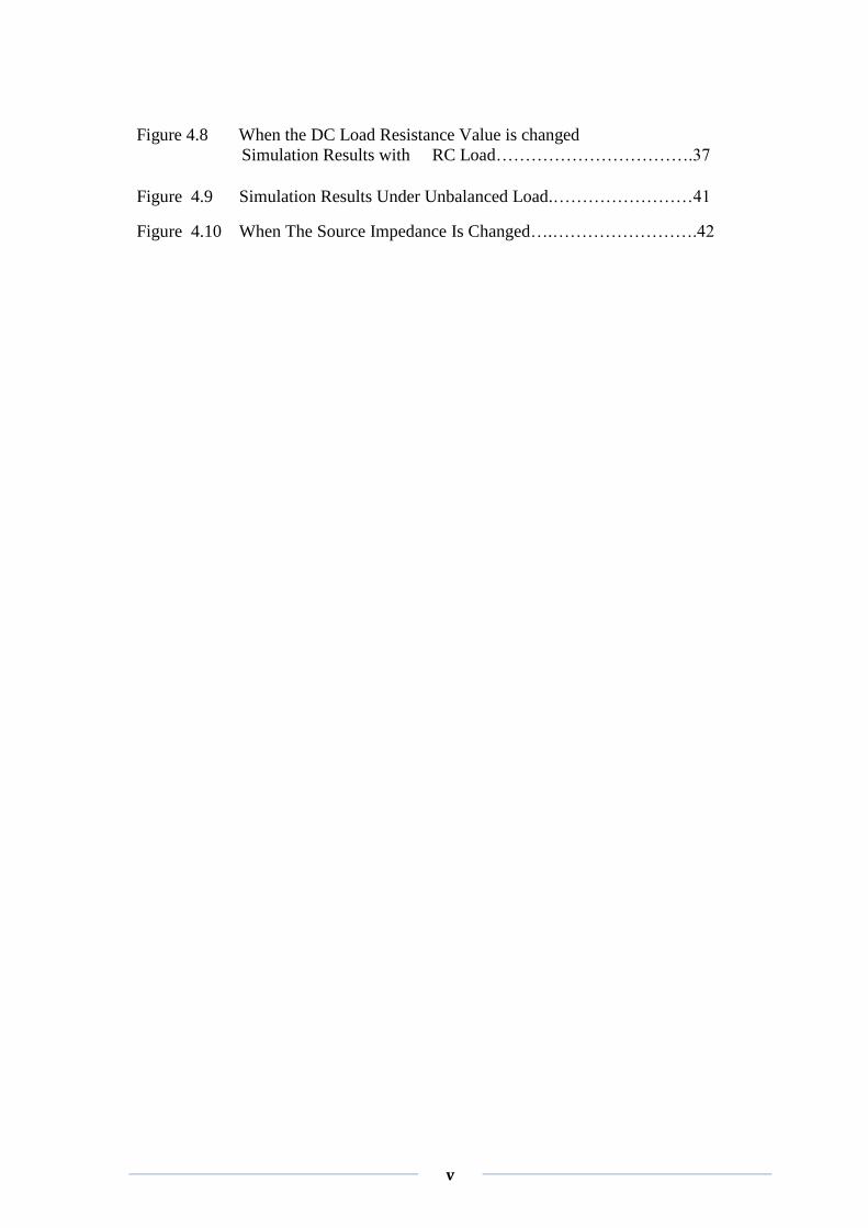
Figure 4.8 When the DC Load Resistance Value is changed
Simulation Results with RC Load…………………………….37
Figure 4.9 Simulation Results Under Unbalanced Load.……………………41
Figure 4.10 When The Source Impedance Is Changed….…………………….42
vi
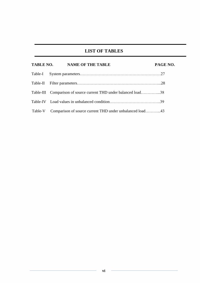
LIST OF TABLES
TABLE NO. NAME OF THE TABLE PAGE NO.
Table-I System parameters……………………………………………………27
Table-II Filter parameters……………………………………………………...28
Table-III Comparison of source current THD under balanced load…………...38
Table-III Table-IV Load values in unbalanced condition………………………………..39
Table-V Comparison of source current THD under unbalanced load………...43

vii

National Institute of Technology, Rourkela Page 1
Chapter1
INTRODUCTION
Literature review
Research motivation
Thesis objectives
Organization of thesis
National Institute of Technology, Rourkela Page 2
1.1 INTRODUCTION
Electrical energy is the most efficient and popular form of energy and the modern society
is heavily dependent on the electric supply. The life cannot be imagined without the
supply of electricity. At the same time the quality of the electric power supplied is also
very important for the efficient functioning of the end user equipment.
The term power quality became most prominent in the power sector and both the electric
power supply company and the end users are concerned about it [1]. The quality of
power delivered to the consumers depends on the voltage and frequency ranges of the
power. If there is any deviation in the voltage and frequency of the electric power
delivered from that of the standard values then the quality of power delivered is affected.
Now-a-days with the advancement in technology there is a drastic improvement in the
semi-conductor devices. With this development and advantages, the semi-conductor
devices got a permanent place in the power sector helping to ease the control of overall
system. Moreover, most of the loads are also semi-conductor based equipment. But the
semi-conductor devices are non-linear in nature and draws non-linear current from the
source. And also the semi-conductor devices are involved in power conversion, which is
either AC to DC or from DC to AC. This power conversion contains lot of switching
operations which may introduce discontinuity in the current. Due to this discontinuity
and non-linearity, harmonics are present which affect the quality of power delivered to
the end user. In order to maintain the quality of power delivered, the harmonics should
be filtered out. Thus, a device named Filter is used which serves this purpose.
There are many filter topologies in the literature like- active, passive and hybrid. In this
project the use of hybrid power filters for the improvement of electric power quality is
studied and analyzed.
1.2 LITERATURE REVIEW
To overcome the problems caused by harmonics, filters are used. There are different
filter topologies present in the literature for this purpose. At first passive filters are used
but they are dependent heavily on the system parameters. They also have the problems of
resonance with system impedance and are suitable for filtering out a particular frequency
harmonics. Therefore, to overcome the problems of passive filters, active filters are used.
National Institute of Technology, Rourkela Page 3
These are used since 1970‟s to compensate the reactive power, negative sequence
currents.
The use of active power filters for power quality improvement is discussed in [2]. In this
paper a review of active filter configuration for power quality improvement is presented
along with control strategies. It is found that the active filters are facing some drawbacks
when employed for power quality improvement. They are-
High converter ratings are required
Costlier when compared to its counterpart, passive filter
Huge size
Increased losses
Therefore, to overcome these drawbacks a hybrid power filter which is a combination of
active and passive filters is proposed in [3]. This paper discusses how a combination of
both active and passive filters is an economical solution for power quality improvement.
To enhance the characteristics of passive filter and also the system, the active filter
should be controlled properly. There are different control techniques for this purpose.
The main aim of any control technique is to make active filter inject a voltage in to the
system that compensates the harmonics. To achieve this output voltage of the active filter
is controlled such that it is equal to a pre-calculated reference value.
The active filter is controlled better with instantaneous reactive power theory. This is
presented in [4] and it discusses the different control algorithms from the formulations of
instantaneous reactive power theory. Finally it concludes that vectorial based theory
yields better results with sinusoidal currents when compared with other algorithms.
The control of series active in conjunction with shunt passive filter using dual
instantaneous reactive power vectorial theory is presented in [5]. In this paper the
proposed theory is validated by simulating it in MATLAB SIMULINK environment.
The proposed control strategy is simulated for both balance and unbalanced load
conditions
National Institute of Technology, Rourkela Page 4
1.3 RESEARCH MOTIVATION
1.3.1 Power Quality Problems:
The quality of power is affected when there is any deviation in the voltage, current or
frequency [6]. The common problems that affect the sensitivity of the equipment are-
Power Surges
Transients
Frequency Variation
Electrical Line Noise
Brownouts or Blackouts
Power System Faults
Improper grounding affect
The main affect caused by these problems is the production of harmonics. The presence
of harmonics deteriorates the quality of power and may damage the end user equipment.
These harmonics causes the heating of underground cables, insulation failure, reduces
the life-time of the equipment, increases the losses etc.
1.3.2 Solutions to Power Quality Problems:
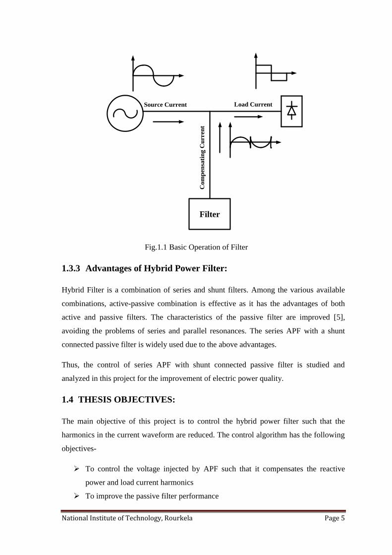
The most effective solution to improve the power quality is the use of filters to reduce
harmonics. The basic idea of using a filter is explained in Fig. 1.1, where the filter injects
a compensating current that compensates the harmonics in load current.
There are different filter topologies in the literature such as- active, passive, hybrid. The
passive power filters are used to filter out a particular order harmonics and has the
problem of parallel resonance. The other solution is the use of Active Power Filter
(APF). There are different types of APF like series APF, shunt APF. The shunt APF is
costly and is not used for large systems. The series APF works as a harmonic isolator and
used to reduce the negative-sequence voltage [2]. There is another filter topology which
is a combination of passive filter and APF known as Hybrid Filter.
National Institute of Technology, Rourkela Page 5
Filter
Source Current Load Current
Com
pen
sati
ng C
urr
ent
Fig.1.1 Basic Operation of Filter
1.3.3 Advantages of Hybrid Power Filter:
Hybrid Filter is a combination of series and shunt filters. Among the various available
combinations, active-passive combination is effective as it has the advantages of both
active and passive filters. The characteristics of the passive filter are improved [5],
avoiding the problems of series and parallel resonances. The series APF with a shunt
connected passive filter is widely used due to the above advantages.
Thus, the control of series APF with shunt connected passive filter is studied and
analyzed in this project for the improvement of electric power quality.
1.4 THESIS OBJECTIVES:
The main objective of this project is to control the hybrid power filter such that the
harmonics in the current waveform are reduced. The control algorithm has the following
objectives-
To control the voltage injected by APF such that it compensates the reactive
power and load current harmonics
To improve the passive filter performance
National Institute of Technology, Rourkela Page 6
To make the whole compensating equipment to act as linear, balanced, resistive
load on the system
1.5 ORGANIZATION OF THESIS:
The whole thesis is organized into five chapters including introduction and each chapter
is summarized below.
Chapter 2 deals with the types of filters available for harmonic reduction. It explains the
merits and demerits of each type of filter with a circuit diagram.
Chapter 3 deals with the control of Hybrid Power Filter. It presents the design of the
compensation strategy which generates a reference value for the output voltage of the
APF that compensates the harmonics in the current waveform.
Chapter 4 deals with the simulation results and discussions. It presents the MATLAB
SIMULINK simulation results of the proposed control strategy at different load
conditions.
Chapter 5 deals with the conclusions work done and the future scope of the project
followed by references.

National Institute of Technology, Rourkela Page 7
Chapter2
TYPES OF FILTERS
Introduction
Filter classification
Chapter summary
National Institute of Technology, Rourkela Page 8
2.1 INTRODUCTION
The electric power system is affected by various problems like transients, noise, voltage
sag/swell, which leads to the production of harmonics and affect the quality of power
delivered to the end user. The harmonics may exist in voltage or current waveforms
which are the integral multiples of the fundamental frequency, which does not contribute
for the active power delivery. Thus the response at these frequencies should be restricted
from affecting the behavior of the system. To achieve this filter is used at the Point of
Common Coupling (PCC) where the load is connected to the supply. This filter filters
out the harmonics and improves the performance of the system. There are different types
of filters available for this purpose. Each of them is explained in detail in this chapter.
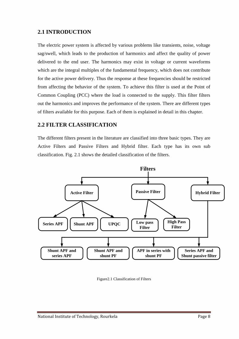
2.2 FILTER CLASSIFICATION
The different filters present in the literature are classified into three basic types. They are
Active Filters and Passive Filters and Hybrid filter. Each type has its own sub
classification. Fig. 2.1 shows the detailed classification of the filters.
Active Filter Passive Filter
UPQCShunt APFSeries APF
Filters
High Pass
FilterLow pass
Filter
Hybrid Filter
Shunt APF and
series APF
Series APF and
Shunt passive filter
APF in series with
shunt PF
Shunt APF and
shunt PF
Figure2.1 Classification of Filters
National Institute of Technology, Rourkela Page 9
2.2.1 Passive Power Filters:
These filters consist of passive elements like- capacitor, inductor and resistor. These are
widely used because of their low cost and ease of control. The passive filters also
provide reactive power apart from filtering the harmonics. The performance of these
filters is heavily dependent on the system impedance. These are again classified into two
types- low pass and high pass.
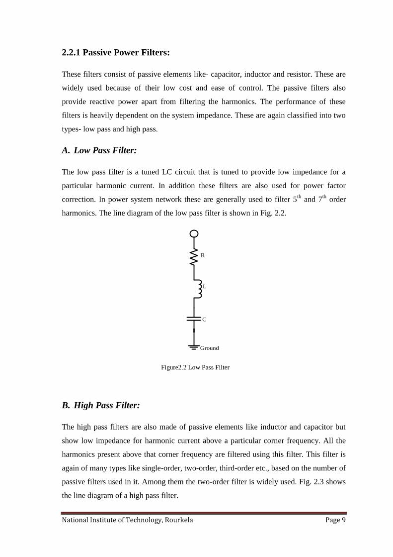
A. Low Pass Filter:
The low pass filter is a tuned LC circuit that is tuned to provide low impedance for a
particular harmonic current. In addition these filters are also used for power factor
correction. In power system network these are generally used to filter 5th
and 7th
order
harmonics. The line diagram of the low pass filter is shown in Fig. 2.2.
R
L
C
Ground
Figure2.2 Low Pass Filter
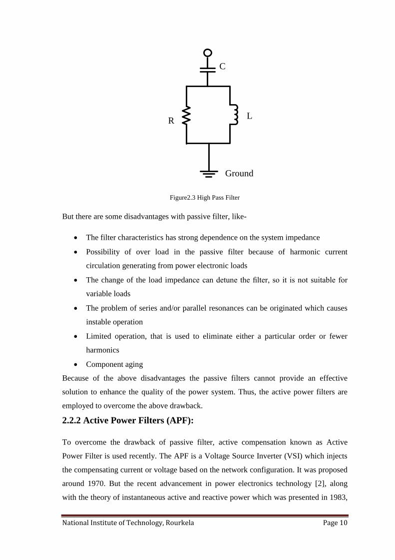
B. High Pass Filter:
The high pass filters are also made of passive elements like inductor and capacitor but
show low impedance for harmonic current above a particular corner frequency. All the
harmonics present above that corner frequency are filtered using this filter. This filter is
again of many types like single-order, two-order, third-order etc., based on the number of
passive filters used in it. Among them the two-order filter is widely used. Fig. 2.3 shows
the line diagram of a high pass filter.
National Institute of Technology, Rourkela Page 10
L R
C
Ground
Figure2.3 High Pass Filter
But there are some disadvantages with passive filter, like-
The filter characteristics has strong dependence on the system impedance
Possibility of over load in the passive filter because of harmonic current
circulation generating from power electronic loads
The change of the load impedance can detune the filter, so it is not suitable for
variable loads
The problem of series and/or parallel resonances can be originated which causes
instable operation
Limited operation, that is used to eliminate either a particular order or fewer
harmonics
Component aging
Because of the above disadvantages the passive filters cannot provide an effective
solution to enhance the quality of the power system. Thus, the active power filters are
employed to overcome the above drawback.
2.2.2 Active Power Filters (APF):
To overcome the drawback of passive filter, active compensation known as Active
Power Filter is used recently. The APF is a Voltage Source Inverter (VSI) which injects
the compensating current or voltage based on the network configuration. It was proposed
around 1970. But the recent advancement in power electronics technology [2], along
with the theory of instantaneous active and reactive power which was presented in 1983,
National Institute of Technology, Rourkela Page 11
APF‟s are an up-to-date solution with fast switching devices, low power loss and fast
digital processing devices at an affordable price. Depending on the circuit configuration
and function, APF‟s are divided into three types and each one is explained in detail
below.
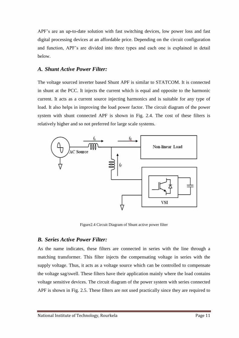
A. Shunt Active Power Filter:
The voltage sourced inverter based Shunt APF is similar to STATCOM. It is connected
in shunt at the PCC. It injects the current which is equal and opposite to the harmonic
current. It acts as a current source injecting harmonics and is suitable for any type of
load. It also helps in improving the load power factor. The circuit diagram of the power
system with shunt connected APF is shown in Fig. 2.4. The cost of these filters is
relatively higher and so not preferred for large scale systems.
Figure2.4 Circuit Diagram of Shunt active power filter
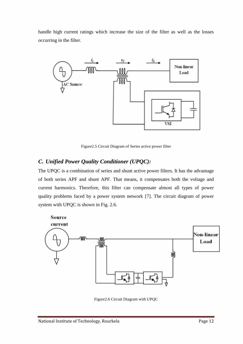
B. Series Active Power Filter:
As the name indicates, these filters are connected in series with the line through a
matching transformer. This filter injects the compensating voltage in series with the
supply voltage. Thus, it acts as a voltage source which can be controlled to compensate
the voltage sag/swell. These filters have their application mainly where the load contains
voltage sensitive devices. The circuit diagram of the power system with series connected
APF is shown in Fig. 2.5. These filters are not used practically since they are required to
National Institute of Technology, Rourkela Page 12
handle high current ratings which increase the size of the filter as well as the losses
occurring in the filter.
Figure2.5 Circuit Diagram of Series active power filter
C. Unified Power Quality Conditioner (UPQC):
The UPQC is a combination of series and shunt active power filters. It has the advantage
of both series APF and shunt APF. That means, it compensates both the voltage and
current harmonics. Therefore, this filter can compensate almost all types of power
quality problems faced by a power system network [7]. The circuit diagram of power
system with UPQC is shown in Fig. 2.6.
Figure2.6 Circuit Diagram with UPQC
National Institute of Technology, Rourkela Page 13
2.2.3 Hybrid Power Filters:
The active power filters are better solution for power quality improvement but they
require high converter ratings. So to overcome the above drawback, hybrid power filters
are designed. The hybrid power filters are the combination of both active and passive
power filters. They have the advantage of both active and passive filters. There are
different hybrid filters based on the circuit combination and arrangement. They are-
Shunt Active Power Filter and Series Active Power Filter
Shunt Active Power Filter and Shunt Passive Filter
Active Power Filter in series with Shunt Passive Filter
Series Active Power Filter with Shunt Passive Filter
Each filter configuration is explained below with their merits and demerits.
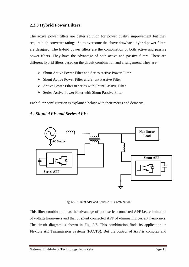
A. Shunt APF and Series APF:
AC Source
Non-linear
Load
Series APF
Shunt APF
Figure2.7 Shunt APF and Series APF Combination
This filter combination has the advantage of both series connected APF i.e., elimination
of voltage harmonics and that of shunt connected APF of eliminating current harmonics.
The circuit diagram is shown in Fig. 2.7. This combination finds its application in
Flexible AC Transmission Systems (FACTS). But the control of APF is complex and
National Institute of Technology, Rourkela Page 14
this combination involves two APF and hence the control of this filter configuration is
even more complex. Thus, this filter combination is not used widely.
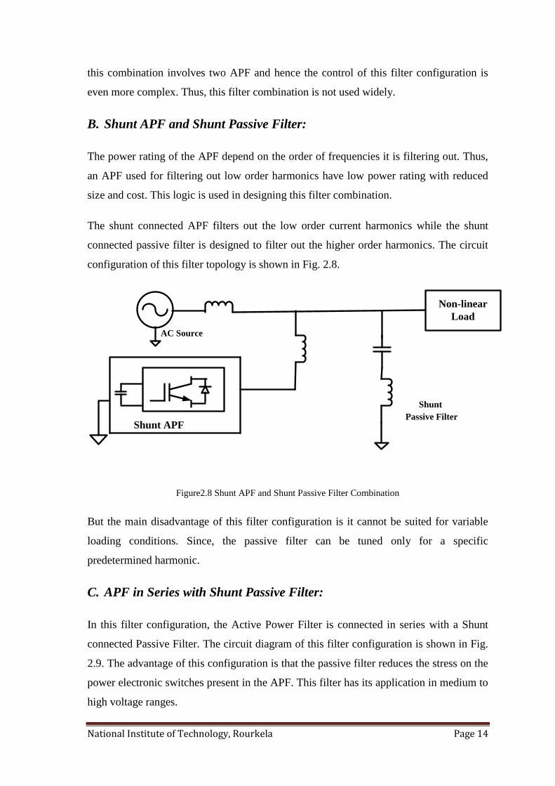
B. Shunt APF and Shunt Passive Filter:
The power rating of the APF depend on the order of frequencies it is filtering out. Thus,
an APF used for filtering out low order harmonics have low power rating with reduced
size and cost. This logic is used in designing this filter combination.
The shunt connected APF filters out the low order current harmonics while the shunt
connected passive filter is designed to filter out the higher order harmonics. The circuit
configuration of this filter topology is shown in Fig. 2.8.
AC Source
Non-linear
Load
Shunt APF
Shunt
Passive Filter
Figure2.8 Shunt APF and Shunt Passive Filter Combination
But the main disadvantage of this filter configuration is it cannot be suited for variable
loading conditions. Since, the passive filter can be tuned only for a specific
predetermined harmonic.
C. APF in Series with Shunt Passive Filter:
In this filter configuration, the Active Power Filter is connected in series with a Shunt
connected Passive Filter. The circuit diagram of this filter configuration is shown in Fig.
2.9. The advantage of this configuration is that the passive filter reduces the stress on the
power electronic switches present in the APF. This filter has its application in medium to
high voltage ranges.
National Institute of Technology, Rourkela Page 15
Non-linear
Load
AC Source
APF in series with
shunt PF
Figure2.9 APF in series with Shunt Connected Passive Filter
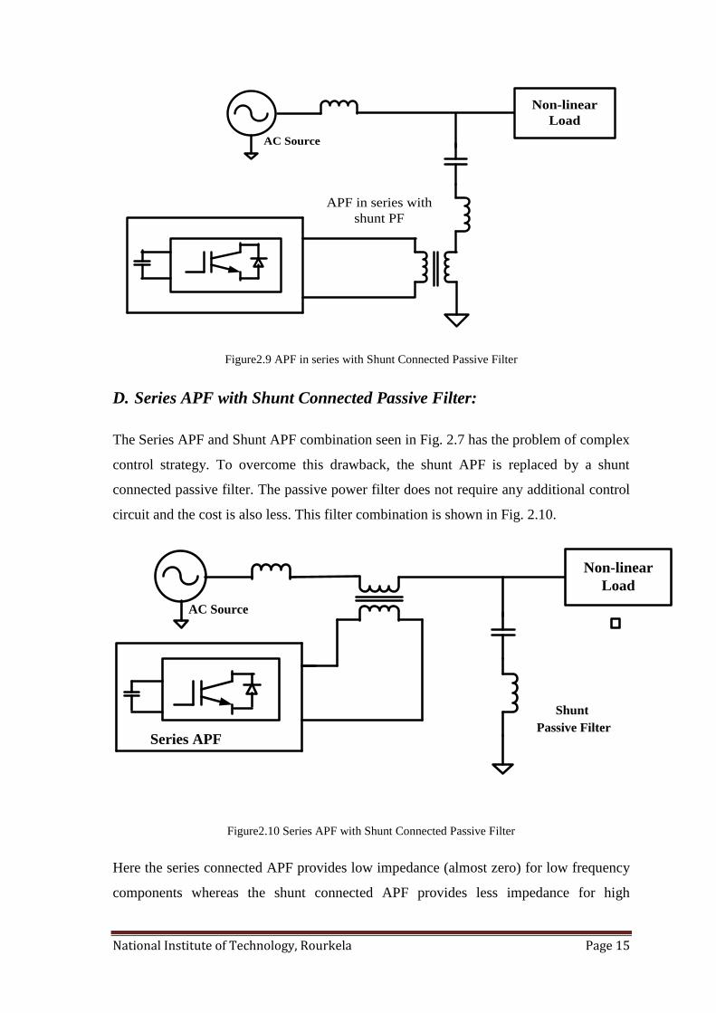
D. Series APF with Shunt Connected Passive Filter:
The Series APF and Shunt APF combination seen in Fig. 2.7 has the problem of complex
control strategy. To overcome this drawback, the shunt APF is replaced by a shunt
connected passive filter. The passive power filter does not require any additional control
circuit and the cost is also less. This filter combination is shown in Fig. 2.10.
AC Source
Non-linear
Load
Series APF
Shunt
Passive Filter
Figure2.10 Series APF with Shunt Connected Passive Filter
Here the series connected APF provides low impedance (almost zero) for low frequency
components whereas the shunt connected APF provides less impedance for high
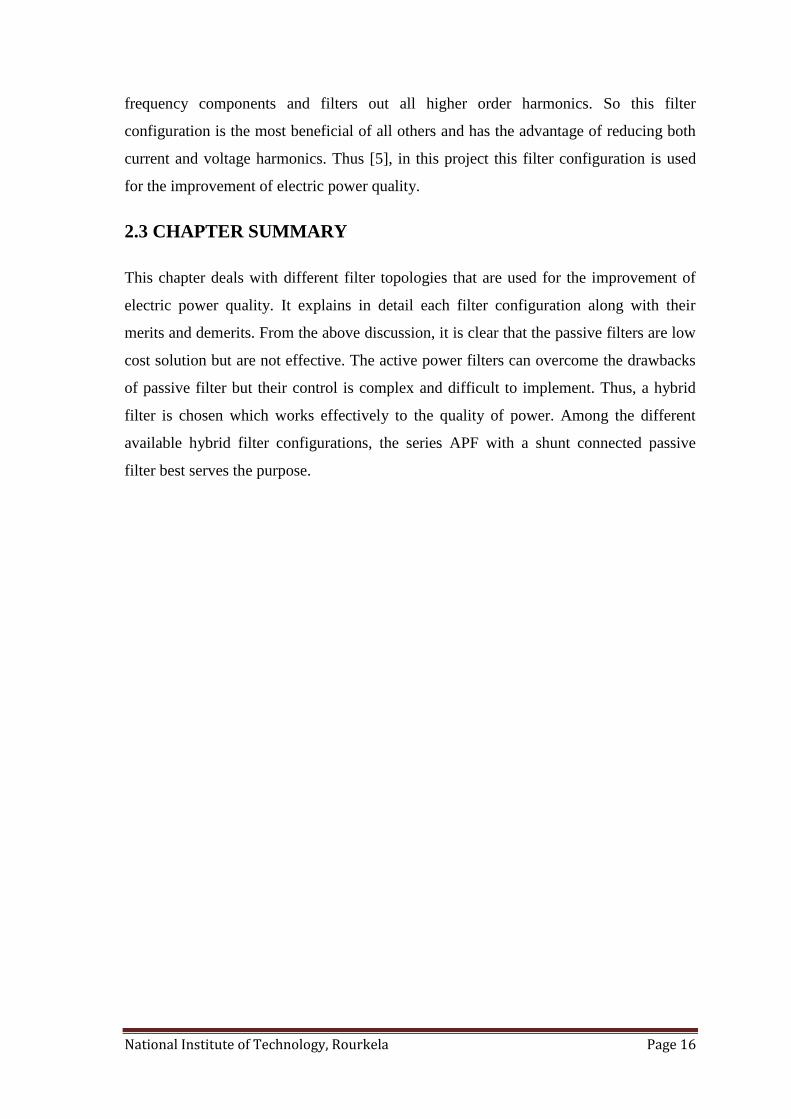
National Institute of Technology, Rourkela Page 16
frequency components and filters out all higher order harmonics. So this filter
configuration is the most beneficial of all others and has the advantage of reducing both
current and voltage harmonics. Thus [5], in this project this filter configuration is used
for the improvement of electric power quality.
2.3 CHAPTER SUMMARY
This chapter deals with different filter topologies that are used for the improvement of
electric power quality. It explains in detail each filter configuration along with their
merits and demerits. From the above discussion, it is clear that the passive filters are low
cost solution but are not effective. The active power filters can overcome the drawbacks
of passive filter but their control is complex and difficult to implement. Thus, a hybrid
filter is chosen which works effectively to the quality of power. Among the different
available hybrid filter configurations, the series APF with a shunt connected passive
filter best serves the purpose.
National Institute of Technology, Rourkela Page 17
Chapter3
CONTROL OF HYBRID POWER FILTER FOR POWER
QUALITY IMPROVEMENT
Introduction
Design of series active power filter
Modeling of series active power filter
Control strategy
Chapter summary
National Institute of Technology, Rourkela Page 18
3.1 INTRODUCTION
The filter is used to reduce the harmonics and improve the power quality. The filter that
is connected to the system should be controlled effectively such that its response
characteristics are as desired. Among the different available filter configurations, hybrid
power filter with series APF and a parallel passive filter is used in this project. The
control circuit of the series connected APF is designed such way that the voltage injected
by the APF compensates the harmonics and also enhances the performance of the shunt
connected passive filter. The control strategy of the hybrid power filter is explained in
detail in this chapter.
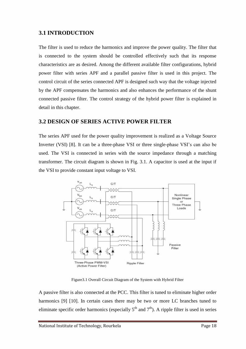
3.2 DESIGN OF SERIES ACTIVE POWER FILTER
The series APF used for the power quality improvement is realized as a Voltage Source
Inverter (VSI) [8]. It can be a three-phase VSI or three single-phase VSI‟s can also be
used. The VSI is connected in series with the source impedance through a matching
transformer. The circuit diagram is shown in Fig. 3.1. A capacitor is used at the input if
the VSI to provide constant input voltage to VSI.
Figure3.1 Overall Circuit Diagram of the System with Hybrid Filter
A passive filter is also connected at the PCC. This filter is tuned to eliminate higher order
harmonics [9] [10]. In certain cases there may be two or more LC branches tuned to
eliminate specific order harmonics (especially 5th
and 7th
). A ripple filter is used in series
National Institute of Technology, Rourkela Page 19
with VSI. The filter parameters are selected such that they do not exceed the transformer
burden. The design criteria is [5]-
XCrf<<XLrf, such that at switching frequency the inverter output voltage drops
across Lrf
XCrf<< ZS + ZF, to make the voltage divide between Lrf and Crf
Thus, with an efficient control strategy, the APF compensates the voltage unbalances and
distortion. The control strategy is designed such that the series APF together with the
passive filter act as a balanced resistive load on the overall system. In a four-wire system,
the harmonic currents circulated in the neutral wire are also reduced due to series APF.
3.3 MODELING OF SERIES ACTIVE POWER FILTER
The modeling of the series Active Power Filter is necessary in order to control the filter.
In this project, the modeling of the series APF which is nothing but a three-phase VSI is
carried out in 2-ϕ stationary reference frame (α-β). Thus, the three phase quantities,
voltage and current vectors, are transformed into α-β co-ordinates by using Clarke‟s
Transformation [11] [12].
In a 3-ϕ three-wire system the voltage vector is represented as-
[ ] (3.1)
The current vector in three-phase system is given as-
[ ] (3.2)
Now these voltage and current vectors are changed into two-phase system using the
transformation matrix-
Therefore, the instantaneous value of real power in the 0-α-β frame can be calculated as-
( ) (3.3)
Here in equation (3.3) v0, i0 represent the zero sequence voltage and zero sequence
current respectively. Their product gives the zero sequence power denoted as p0. Thus,
the equation (3.3) can be written as-
( ) (3.4)
National Institute of Technology, Rourkela Page 20
Here P represents the instantaneous real power and is written as-
(3.5)
The power can be represented in vectorial form using dot product. Hence the active
power when represented in vector form can be written as-
(3.6)
Here the transposed current vector in α-β coordinates and is the voltage vector in
α-β coordinates and are given by equations (3.7) and (3.8) respectively.
[ ] (3.7)
[ ] (3.8)
In a three-phase three-wire system, the zero sequence power will be zero and hence the
term p0 in equation (3.4) can be neglected. The instantaneous imaginary power can be
obtained by the equation (3.9) as-
(3.9)
The above equation can be expressed in vector form as-
(3.10)
Where is the transposed current vector perpendicular to and is giving by
equation (3.11) as-
[ ] (3.11)
When the instantaneous real and reactive power in equations (3.6) and (3.10) are
expressed in matrix form then the matrix equation is-
[ ] [
] (3.12)
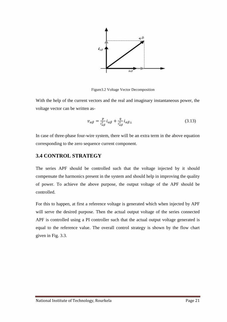
The voltage vector can be decomposed in its orthogonal projection on the current vector
axis as shown in Fig. 3.2.
National Institute of Technology, Rourkela Page 21
Figure3.2 Voltage Vector Decomposition
With the help of the current vectors and the real and imaginary instantaneous power, the
voltage vector can be written as-
(3.13)
In case of three-phase four-wire system, there will be an extra term in the above equation
corresponding to the zero sequence current component.
3.4 CONTROL STRATEGY
The series APF should be controlled such that the voltage injected by it should
compensate the harmonics present in the system and should help in improving the quality
of power. To achieve the above purpose, the output voltage of the APF should be
controlled.
For this to happen, at first a reference voltage is generated which when injected by APF
will serve the desired purpose. Then the actual output voltage of the series connected
APF is controlled using a PI controller such that the actual output voltage generated is
equal to the reference value. The overall control strategy is shown by the flow chart
given in Fig. 3.3.
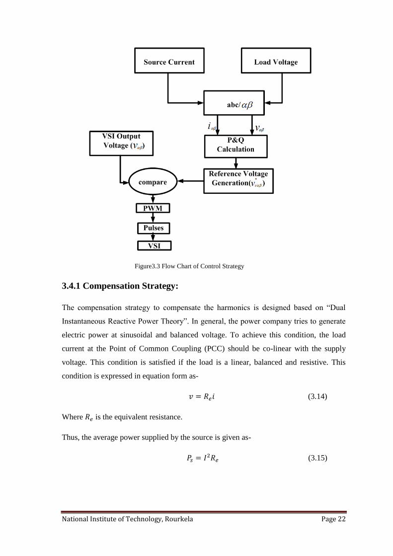
National Institute of Technology, Rourkela Page 22
Figure3.3 Flow Chart of Control Strategy
3.4.1 Compensation Strategy:
The compensation strategy to compensate the harmonics is designed based on “Dual
Instantaneous Reactive Power Theory”. In general, the power company tries to generate
electric power at sinusoidal and balanced voltage. To achieve this condition, the load
current at the Point of Common Coupling (PCC) should be co-linear with the supply
voltage. This condition is satisfied if the load is a linear, balanced and resistive. This
condition is expressed in equation form as-
(3.14)
Where is the equivalent resistance.
Thus, the average power supplied by the source is given as-
(3.15)
National Institute of Technology, Rourkela Page 23
In case of unbalanced loads, where harmonics exist, only the fundamental component of
the current helps in supplying the active power to the load. So the current in the equation
(3.15) is only the fundamental component and is represented as I1.
The load power is the summation of the source power and the compensator power. But
the power exchange by the compensator should be null. So the load power is equal to the
source power.
Therefore, the equivalent resistance is obtained as-
(3.16)
Thus, the voltage at the PCC in α-β co-ordinates is obtained as-
(3.17)
By substituting equation (3.16) in (3.17) the voltage at PCC is obtained as-
(3.18)
From equation (3.13) the load voltage can be written as-
(3.19)
Thus, the compensating voltage of the series APF is obtained as-
(3.20)
From equations (3.18) and (3.19) the equation (3.20) is modified as-
(
)
(3.21)
This is the reference value of the voltage that is to be supplied by the APF in order to
make the set load and compensating equipment to act as resistive load.
National Institute of Technology, Rourkela Page 24
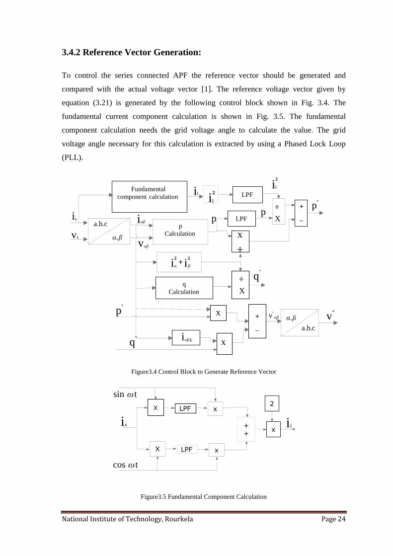
3.4.2 Reference Vector Generation:
To control the series connected APF the reference vector should be generated and
compared with the actual voltage vector [1]. The reference voltage vector given by
equation (3.21) is generated by the following control block shown in Fig. 3.4. The
fundamental current component calculation is shown in Fig. 3.5. The fundamental
component calculation needs the grid voltage angle to calculate the value. The grid
voltage angle necessary for this calculation is extracted by using a Phased Lock Loop
(PLL).
Figure3.4 Control Block to Generate Reference Vector
Figure3.5 Fundamental Component Calculation
Fundamental component calculation LPF
p Calculation
q Calculation
X
÷
LPF
i l 2 i l
i l 2
÷
x
_
+ p *
p p
i αβ
v αβ
i s
v L
c . b . a
β α .
i i 2 2
+ β α
i ⊥ αβ
x
x
_
+ β α .
c . b . a
v * p
*
q *
X
÷
v * αβ
LPF
X x
x X
LPF
+ +
x
2
i s i l
t sin ω
t cos ω
q *
National Institute of Technology, Rourkela Page 25
A Low pass filter (LPF) is used in the fundamental calculation block to filter out the
harmonics and extract the fundamental component. A comparison is made between the
actual and reference values of the output voltage of APF. The error is passed through a
PI controller. The gain values of the controller are tuned in such a way that the error is
zero and the actual value matches almost with the reference value. If this condition is
achieved perfectly then the series APF improves the quality of power generated to the
load by filtering out the harmonics and thus improving the performance of the system.
3.5 CHAPTER SUMMARY
This chapter deals with the control of the series Active Power Filter. It explains how the
APF is controlled such that the power quality is improved. The mathematical model of
the series APF is derived and the generation of the reference voltage vector is explained
in detail. The control algorithm is based on Dual Instantaneous Electric Power Vectorial
Theory. The overall control algorithm is designed such that the compensating equipment
(filter) and the load together act as a resistive load on the supply system.

National Institute of Technology, Rourkela Page 26
Chapter4
SIMULATION RESULTS AND DISCUSSIONS
Introduction
Simulation results with balanced load
Simulation results with unbalanced load
Chapter summary
National Institute of Technology, Rourkela Page 27
4.1 INTRODUCTION
The proposed control strategy is simulated in MATLAB SIMULINK environment to
check the performance of the control strategy in improving the system behavior. The
simulation is carried under two different load conditions-
Non-linear Balanced Load
Non-linear Unbalanced Load
The performance of the system with the proposed control strategy under different load
conditions is discussed in detail in the following section.
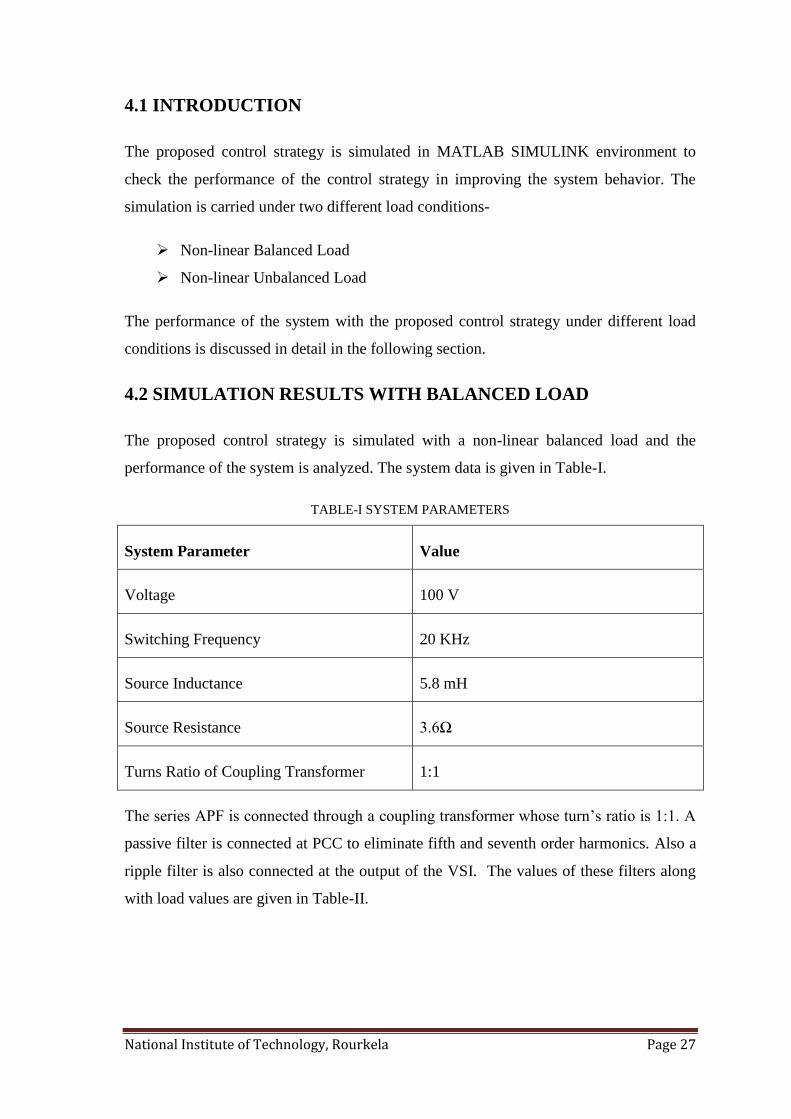
4.2 SIMULATION RESULTS WITH BALANCED LOAD
The proposed control strategy is simulated with a non-linear balanced load and the
performance of the system is analyzed. The system data is given in Table-I.
TABLE-I SYSTEM PARAMETERS
System Parameter Value
Voltage 100 V
Switching Frequency 20 KHz
Source Inductance 5.8 mH
Source Resistance 3.6Ω
Turns Ratio of Coupling Transformer 1:1
The series APF is connected through a coupling transformer whose turn‟s ratio is 1:1. A
passive filter is connected at PCC to eliminate fifth and seventh order harmonics. Also a
ripple filter is also connected at the output of the VSI. The values of these filters along
with load values are given in Table-II.
National Institute of Technology, Rourkela Page 28
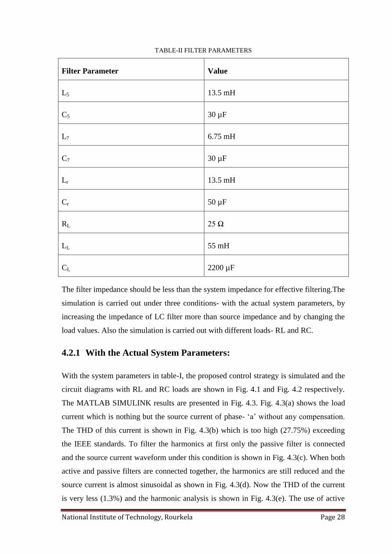
TABLE-II FILTER PARAMETERS
Filter Parameter Value
L5 13.5 mH
C5 30 µF
L7 6.75 mH
C7 30 µF
Lr 13.5 mH
Cr 50 µF
RL 25 Ω
LL 55 mH
CL 2200 µF
The filter impedance should be less than the system impedance for effective filtering.The
simulation is carried out under three conditions- with the actual system parameters, by
increasing the impedance of LC filter more than source impedance and by changing the
load values. Also the simulation is carried out with different loads- RL and RC.
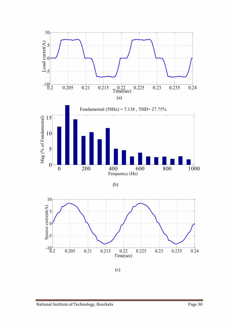
4.2.1 With the Actual System Parameters:
With the system parameters in table-I, the proposed control strategy is simulated and the
circuit diagrams with RL and RC loads are shown in Fig. 4.1 and Fig. 4.2 respectively.
The MATLAB SIMULINK results are presented in Fig. 4.3. Fig. 4.3(a) shows the load
current which is nothing but the source current of phase- „a‟ without any compensation.
The THD of this current is shown in Fig. 4.3(b) which is too high (27.75%) exceeding
the IEEE standards. To filter the harmonics at first only the passive filter is connected
and the source current waveform under this condition is shown in Fig. 4.3(c). When both
active and passive filters are connected together, the harmonics are still reduced and the
source current is almost sinusoidal as shown in Fig. 4.3(d). Now the THD of the current
is very less (1.3%) and the harmonic analysis is shown in Fig. 4.3(e). The use of active

National Institute of Technology, Rourkela Page 29
power filter increases the performance of the system and the overall power factor is also
improved. In addition, the characteristics of the passive filter are also improved and the
5th
and 7th
order harmonics are greatly reduced. The corresponding simulation results
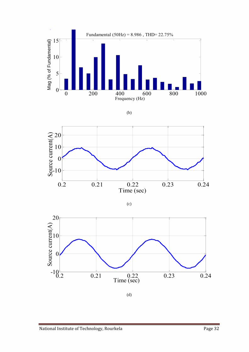
with RC load is shown in Fig. 4.4.
Figure4.1 Simulation Diagram with RL-Load
Figure4.2 Simulation Diagram with RC-Load
v a
v c
v b
L s
L s
L s
C rf C rf C rf
L rf L rf L rf L 5 L 5 L 5 L 7 L 7 L 7
Non-linear load
v a
v c
v b
L s
L s
L s
C rf C rf C rf
L rf L rf L rf L 5 L 5 L 5 L 7 L 7 L 7
Non-linear load
National Institute of Technology, Rourkela Page 30
(a)
(b)
(c)
0.2 0.205 0.21 0.215 0.22 0.225 0.23 0.235 0.24-10
-5
0
5
10
Time(sec)
Lo
ad
cu
rret(
A)
0.2 0.205 0.21 0.215 0.22 0.225 0.23 0.235 0.24-10
-5
0
5
10
Time(sec)
So
urc
e c
urr
en
t(A
)
0 200 400 600 800 10000
5
10
15
Frequency (Hz)
Fundamental (50Hz) = 7.138 , THD= 27.75%
Mag
(%
of
Fu
nd
amen
tal)
National Institute of Technology, Rourkela Page 31
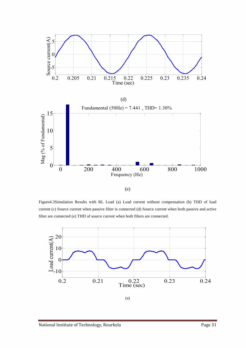
(d)
(e)
Figure4.3Simulation Results with RL Load (a) Load current without compensation (b) THD of load
current (c) Source current when passive filter is connected (d) Source current when both passive and active
filter are connected (e) THD of source current when both filters are connected.
(a)
0.2 0.205 0.21 0.215 0.22 0.225 0.23 0.235 0.24
-5
0
5
Time (sec)
So
urc
e c
urr
en
t(A
)
0 200 400 600 800 10000
5
10
15
Frequency (Hz)
Fundamental (50Hz) = 7.441 , THD= 1.30%
Mag
(%
of
Fu
nd
amen
tal)
0.2 0.21 0.22 0.23 0.24
-10
0
10
20
Time (sec)
Loa
d cu
rren
t(A
)
National Institute of Technology, Rourkela Page 32
(b)
(c)
(d)
0 200 400 600 800 10000
5
10
15
Frequency (Hz)
Fundamental (50Hz) = 8.986 , THD= 22.75%
Mag (
% o
f F
undam
enta
l)
0.2 0.21 0.22 0.23 0.24
-10
0
10
20
Time (sec)
So
urc
e cu
rren
t(A
)
0.2 0.21 0.22 0.23 0.24-10
0
10
20
Time (sec)
So
urc
e cu
rren
t(A
)
National Institute of Technology, Rourkela Page 33
(e)
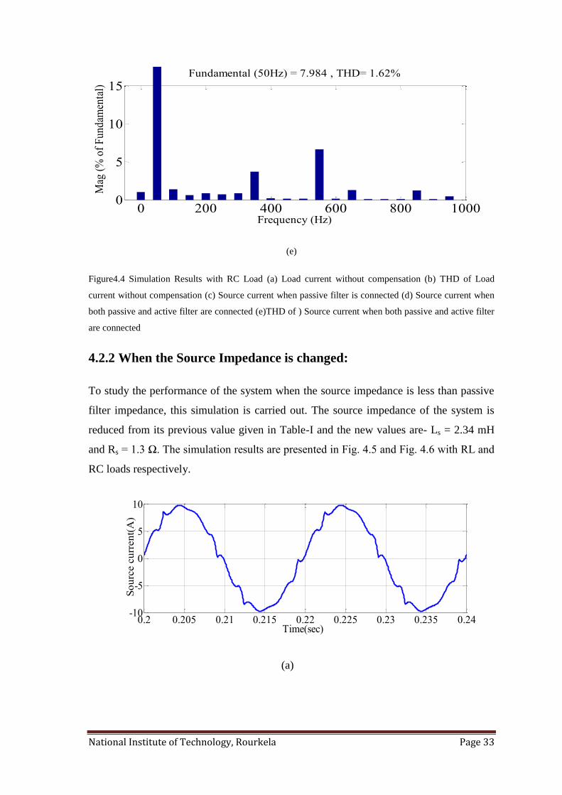
Figure4.4 Simulation Results with RC Load (a) Load current without compensation (b) THD of Load
current without compensation (c) Source current when passive filter is connected (d) Source current when
both passive and active filter are connected (e)THD of ) Source current when both passive and active filter
are connected
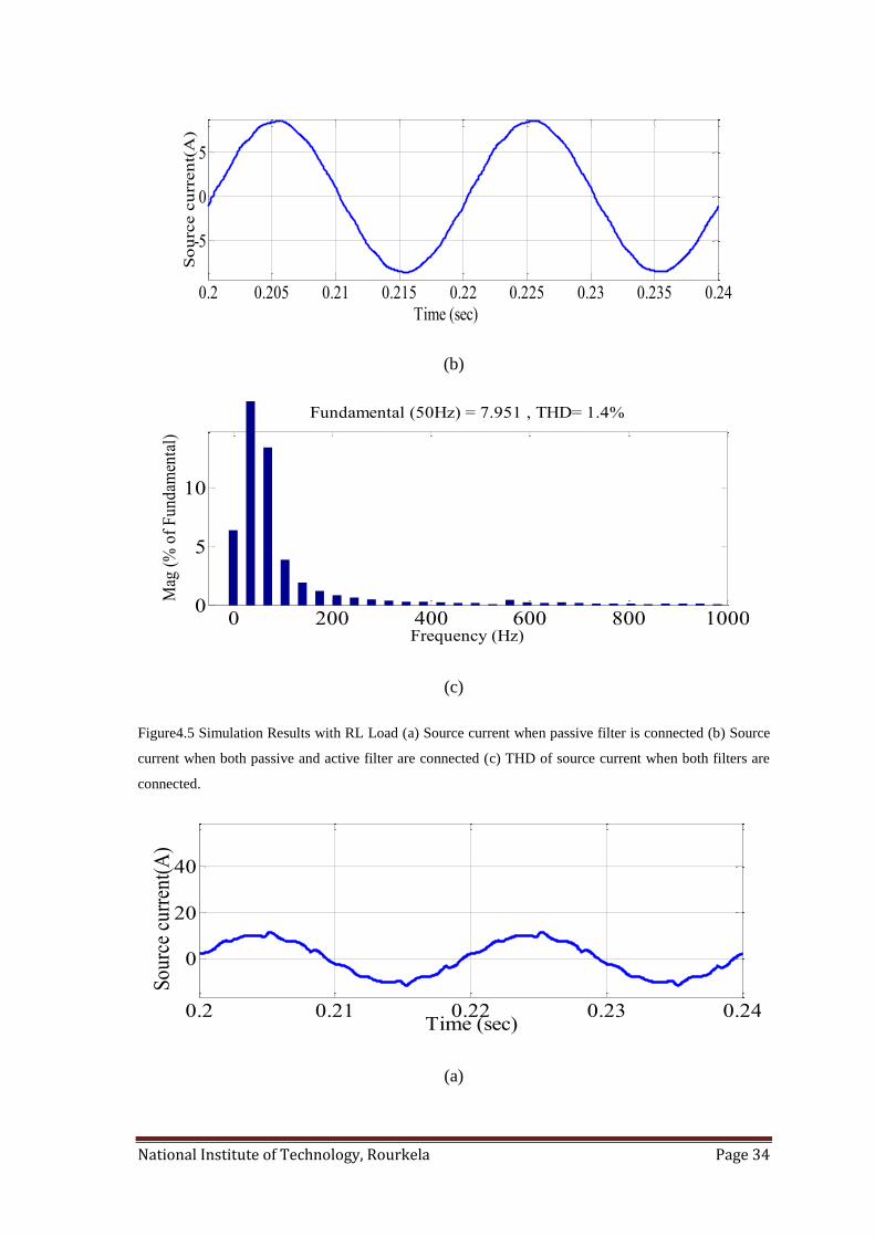
4.2.2 When the Source Impedance is changed:
To study the performance of the system when the source impedance is less than passive
filter impedance, this simulation is carried out. The source impedance of the system is
reduced from its previous value given in Table-I and the new values are- Ls = 2.34 mH
and Rs = 1.3 Ω. The simulation results are presented in Fig. 4.5 and Fig. 4.6 with RL and
RC loads respectively.
(a)
0 200 400 600 800 10000
5
10
15
Frequency (Hz)
Fundamental (50Hz) = 7.984 , THD= 1.62%
Mag
(%
of
Fu
nd
amen
tal)
0.2 0.205 0.21 0.215 0.22 0.225 0.23 0.235 0.24-10
-5
0
5
10
Time(sec)
So
urc
e c
urr
en
t(A
)
National Institute of Technology, Rourkela Page 34
(b)
(c)
Figure4.5 Simulation Results with RL Load (a) Source current when passive filter is connected (b) Source
current when both passive and active filter are connected (c) THD of source current when both filters are
connected.
(a)
0.2 0.205 0.21 0.215 0.22 0.225 0.23 0.235 0.24
-5
0
5
Time (sec)
So
urc
e c
urr
en
t(A
)
0 200 400 600 800 10000
5
10
Frequency (Hz)
Fundamental (50Hz) = 7.951 , THD= 1.4%
Mag
(%
of
Fu
nd
amen
tal)
0.2 0.21 0.22 0.23 0.24
0
20
40
Time (sec)
So
urc
e cu
rren
t(A
)
National Institute of Technology, Rourkela Page 35
(b)
c)
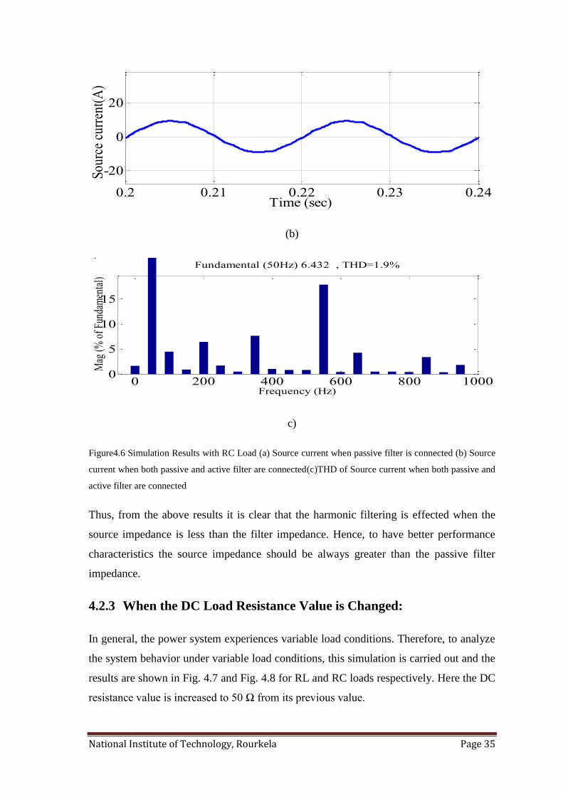
Figure4.6 Simulation Results with RC Load (a) Source current when passive filter is connected (b) Source
current when both passive and active filter are connected(c)THD of Source current when both passive and
active filter are connected
Thus, from the above results it is clear that the harmonic filtering is effected when the
source impedance is less than the filter impedance. Hence, to have better performance
characteristics the source impedance should be always greater than the passive filter
impedance.
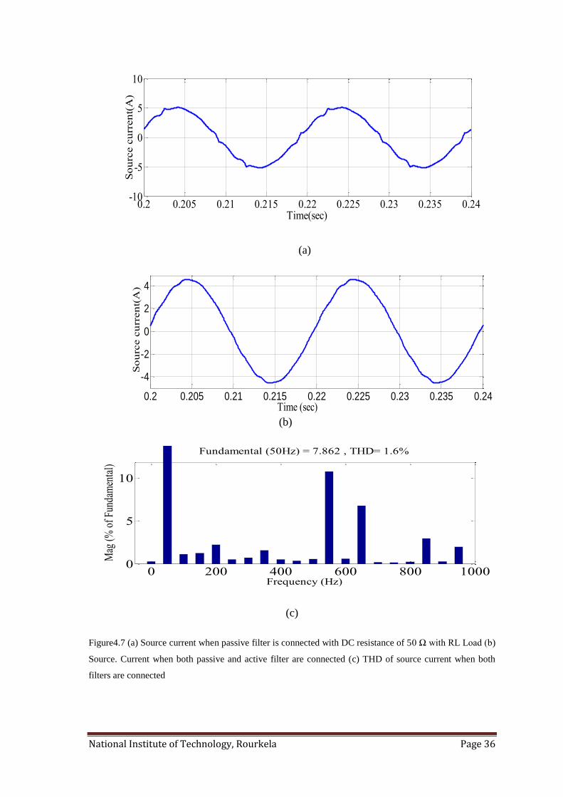
4.2.3 When the DC Load Resistance Value is Changed:
In general, the power system experiences variable load conditions. Therefore, to analyze
the system behavior under variable load conditions, this simulation is carried out and the
results are shown in Fig. 4.7 and Fig. 4.8 for RL and RC loads respectively. Here the DC
resistance value is increased to 50 Ω from its previous value.
0.2 0.21 0.22 0.23 0.24
-20
0
20
Time (sec)
Sou
rce
curr
ent(
A)
0 200 400 600 800 10000
5
10
15
Frequency (Hz)
Fundamental (50Hz) 6.432 , THD=1.9%
Mag
(% o
f Fun
dam
enta
l)
National Institute of Technology, Rourkela Page 36
(a)
(b)
(c)
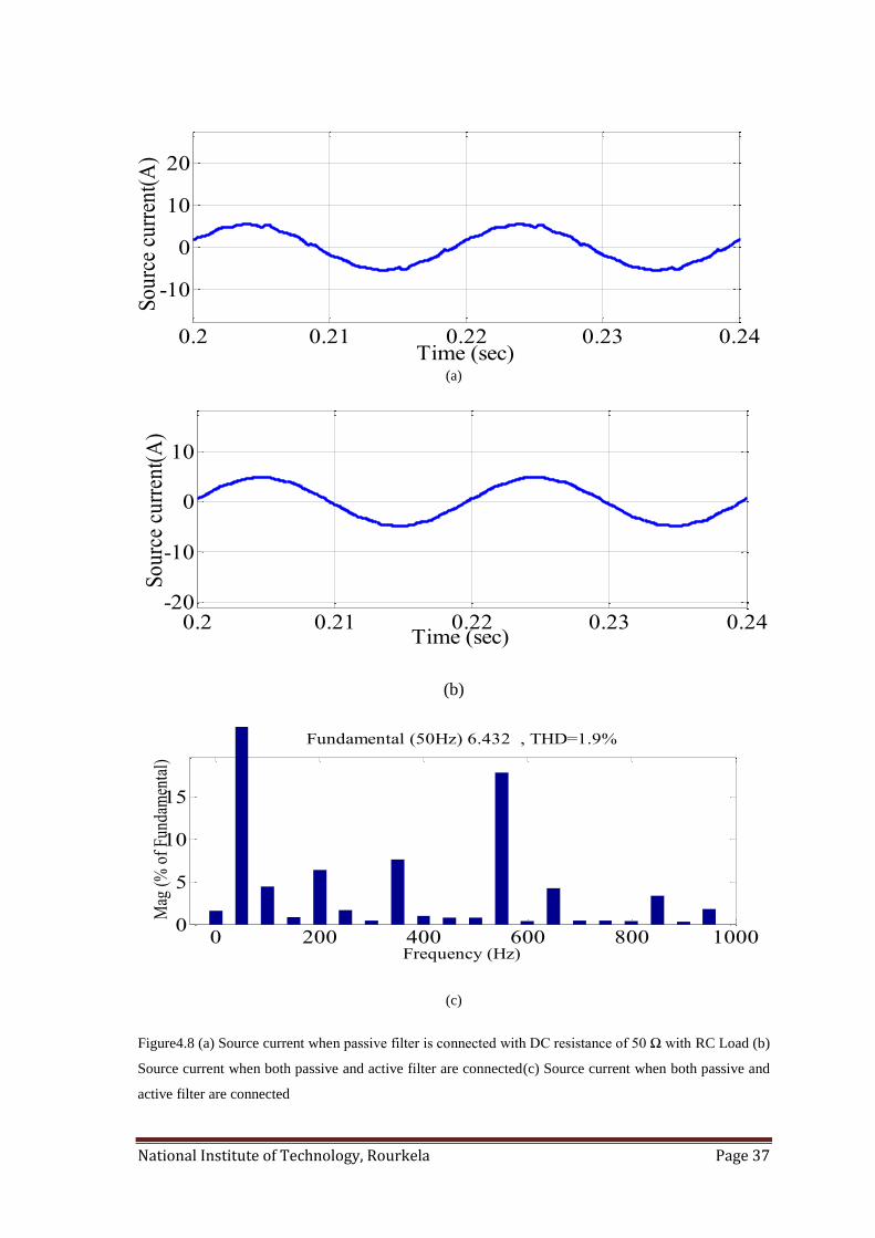
Figure4.7 (a) Source current when passive filter is connected with DC resistance of 50 Ω with RL Load (b)
Source. Current when both passive and active filter are connected (c) THD of source current when both
filters are connected
0.2 0.205 0.21 0.215 0.22 0.225 0.23 0.235 0.24-10
-5
0
5
10
Time(sec)
So
urc
e c
urr
en
t(A
)
0 200 400 600 800 10000
5
10
Frequency (Hz)
Fundamental (50Hz) = 7.862 , THD= 1.6%
Mag
(%
of
Fund
amen
tal)
0.2 0.205 0.21 0.215 0.22 0.225 0.23 0.235 0.24
-4
-2
0
2
4
Time (sec)
So
urc
e c
urr
en
t(A
)
National Institute of Technology, Rourkela Page 37
(a)
(b)
(c)
Figure4.8 (a) Source current when passive filter is connected with DC resistance of 50 Ω with RC Load (b)
Source current when both passive and active filter are connected(c) Source current when both passive and
active filter are connected
0.2 0.21 0.22 0.23 0.24-20
-10
0
10
Time (sec)
So
urc
e cu
rren
t(A
)
0 200 400 600 800 10000
5
10
15
Frequency (Hz)
Fundamental (50Hz) 6.432 , THD=1.9%
Mag
(%
of
Fun
dam
enta
l)
0.2 0.21 0.22 0.23 0.24
-10
0
10
20
Time (sec)
So
urc
e cu
rren
t(A
)

National Institute of Technology, Rourkela Page 38
4.2.4 Comparative Study Under Balanced Load Condition:
A comparative study is made to analyze the performance of the system at various
operating conditions when operating with balanced load. The comparison is given in
Table- III. From the results it is clear that the system behavior is improved when active
filter is connected and the source current THD is very less and is within the IEEE
permissible standards.
TABLE-III COPMARISON OF SOURCE CURRENT THD UNDER BALANCED LOAD
NAME THD with only
Passive Filter
THD with Active
& Passive Filters
RL load with actual system parameters 5.7% 1.3%
RL load with source impedance Ls = 2.34 mH
and Rs = 1.3 Ω
10.6% 1.4%
RL load with the resistor on the dc side is 50
ohm
4.6% 1.6%
RC load with actual system parameters 4.5% 1.62%
RC load with source impedance Ls = 2.34 mH
and Rs = 1.3 Ω
8.9% 1.9%
RL load with the resistor on the dc side is 50
ohm
4.4% 1.9%
4.3 SIMULATION RESULTS WITH UNBALANCED LOAD
The power system may experience unbalanced load conditions at many times. Thus, the
behavior of the proposed control strategy is analyzed by simulating it under unbalanced
loading conditions. Here the unbalanced load is created by connecting three single-phase
uncontrolled rectifiers with capacitor and resistor in parallel on the DC side. The load
values are given Table-IV.
National Institute of Technology, Rourkela Page 39
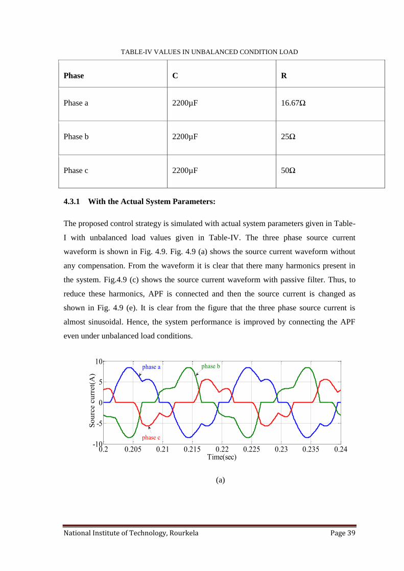
TABLE-IV VALUES IN UNBALANCED CONDITION LOAD
Phase C R
Phase a 2200µF 16.67Ω
Phase b 2200µF 25Ω
Phase c 2200µF 50Ω
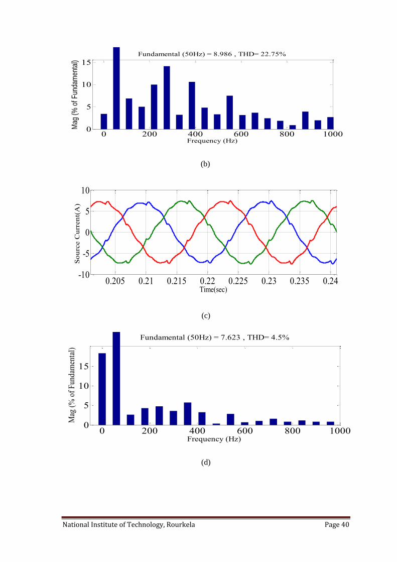
4.3.1 With the Actual System Parameters:
The proposed control strategy is simulated with actual system parameters given in Table-
I with unbalanced load values given in Table-IV. The three phase source current
waveform is shown in Fig. 4.9. Fig. 4.9 (a) shows the source current waveform without
any compensation. From the waveform it is clear that there many harmonics present in
the system. Fig.4.9 (c) shows the source current waveform with passive filter. Thus, to
reduce these harmonics, APF is connected and then the source current is changed as
shown in Fig. 4.9 (e). It is clear from the figure that the three phase source current is
almost sinusoidal. Hence, the system performance is improved by connecting the APF
even under unbalanced load conditions.
(a)
0.2 0.205 0.21 0.215 0.22 0.225 0.23 0.235 0.24-10
-5
0
5
10
Time(sec)
So
urc
e c
urr
et(
A)
phase a phase b
phase c
National Institute of Technology, Rourkela Page 40
(b)
(c)
(d)
0 200 400 600 800 10000
5
10
15
Frequency (Hz)
Fundamental (50Hz) = 8.986 , THD= 22.75%
Mag
(%
of F
unda
men
tal)
0.205 0.21 0.215 0.22 0.225 0.23 0.235 0.24-10
-5
0
5
10
Time(sec)
So
urc
e C
urr
en
t(A
)
0 200 400 600 800 10000
5
10
15
Frequency (Hz)
Fundamental (50Hz) = 7.623 , THD= 4.5%
Mag
(%
of
Fun
dam
enta
l)
National Institute of Technology, Rourkela Page 41
(e)
(f)
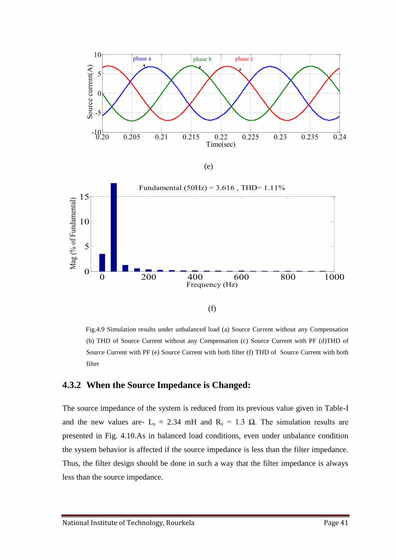
Fig.4.9 Simulation results under unbalanced load (a) Source Current without any Compensation
(b) THD of Source Current without any Compensation (c) Source Current with PF (d)THD of
Source Current with PF (e) Source Current with both filter (f) THD of Source Current with both
filter
4.3.2 When the Source Impedance is Changed:
The source impedance of the system is reduced from its previous value given in Table-I
and the new values are- Ls = 2.34 mH and Rs = 1.3 Ω. The simulation results are
presented in Fig. 4.10.As in balanced load conditions, even under unbalance condition
the system behavior is affected if the source impedance is less than the filter impedance.
Thus, the filter design should be done in such a way that the filter impedance is always
less than the source impedance.
0.20 0.205 0.21 0.215 0.22 0.225 0.23 0.235 0.24-10
-5
0
5
10
Time(sec)
So
urc
e c
urr
ent(
A)
phase bphase a phase c
0 200 400 600 800 10000
5
10
15
Frequency (Hz)
Fundamental (50Hz) = 3.616 , THD= 1.11%
Mag
(%
of
Fun
dam
enta
l)
National Institute of Technology, Rourkela Page 42
(a)
(b)
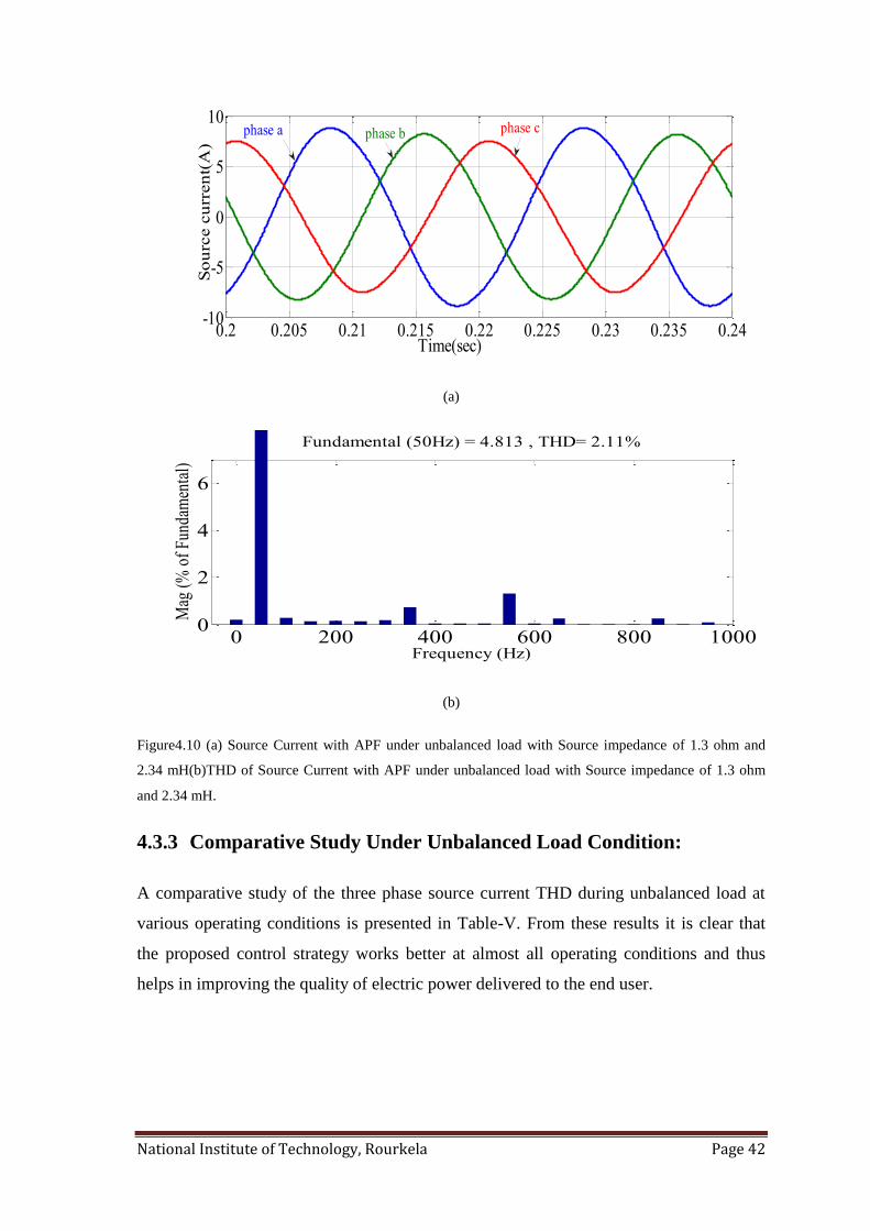
Figure4.10 (a) Source Current with APF under unbalanced load with Source impedance of 1.3 ohm and
2.34 mH(b)THD of Source Current with APF under unbalanced load with Source impedance of 1.3 ohm
and 2.34 mH.
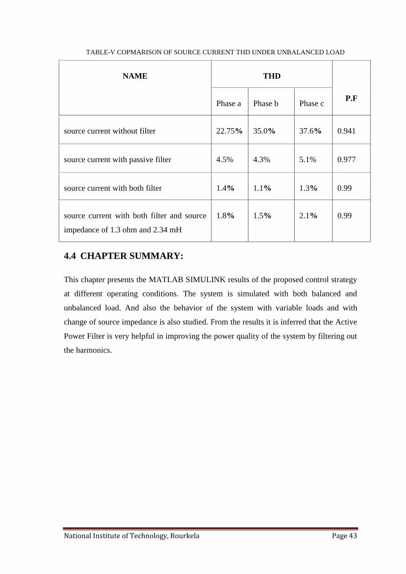
4.3.3 Comparative Study Under Unbalanced Load Condition:
A comparative study of the three phase source current THD during unbalanced load at
various operating conditions is presented in Table-V. From these results it is clear that
the proposed control strategy works better at almost all operating conditions and thus
helps in improving the quality of electric power delivered to the end user.
0.2 0.205 0.21 0.215 0.22 0.225 0.23 0.235 0.24-10
-5
0
5
10
Time(sec)
So
urc
e c
urr
en
t(A
)
phase bphase a phase c
0 200 400 600 800 10000
2
4
6
Frequency (Hz)
Fundamental (50Hz) = 4.813 , THD= 2.11%
Mag
(%
of
Fund
amen
tal)
National Institute of Technology, Rourkela Page 43
TABLE-V COPMARISON OF SOURCE CURRENT THD UNDER UNBALANCED LOAD
NAME THD
P.F Phase a Phase b Phase c
source current without filter 22.75% 35.0% 37.6% 0.941
source current with passive filter 4.5% 4.3% 5.1% 0.977
source current with both filter 1.4% 1.1% 1.3% 0.99
source current with both filter and source
impedance of 1.3 ohm and 2.34 mH
1.8% 1.5% 2.1% 0.99
4.4 CHAPTER SUMMARY:
This chapter presents the MATLAB SIMULINK results of the proposed control strategy
at different operating conditions. The system is simulated with both balanced and
unbalanced load. And also the behavior of the system with variable loads and with
change of source impedance is also studied. From the results it is inferred that the Active
Power Filter is very helpful in improving the power quality of the system by filtering out
the harmonics.

National Institute of Technology, Rourkela Page 44
Chapter5
CONCLUSION AND SCOPE OF FUTUREWORK
Conclusions
Future scope
National Institute of Technology, Rourkela Page 45
5.1 CONCLUSIONS
The demand for electric power is increasing at an exponential rate and at the same time
the quality of power delivered became the most prominent issue in the power sector.
Thus, the reduction of harmonics and improving the power factor of the system is of
utmost important. In this project a solution to improve the electric power quality by the
use of Active Power Filter is discussed. From the study of Active Power Filter for power
quality improvement the following conclusions are drawn-
Most of the loads connected to the system are non-linear which are the major
source of harmonics in the system
The non-linear load draws non-linear current from the supply
Thus the voltage at PCC is also non-linear affecting the performance of end user
equipment
To compensate the load harmonics a filter is connected at the PCC which injects
the compensating current
To achieve this a Hybrid power filter with series connected APF and shunt
connected passive filter is used
The APF is controlled based on the Dual Instantaneous Reactive Power Theory to
compensate the load harmonics
Simulation of the proposed control strategy show the behavior of APF under
different operating conditions
The connection of APF improves the passive filter characteristics in addition to
improve the system performance
The APF works well even with variable loads and improves the power factor of
the system
The simulation is also carried out with unbalanced load and found that the APF
improves the system behavior by reducing the harmonics
Therefore, it is concluded that the hybrid filter consisting of series APF and a shunt
passive filter is a feasible economic solution for improving the power quality in electric
power system.

National Institute of Technology, Rourkela Page 46
5.2 FUTURE SCOPE:
The work done in this project can be further extended such new improvements can be
found. The feasible options are-
To simulate the proposed control strategy with grid faults and study the behavior
of APF in power quality improvement
To implement the control strategy using Artificial Intelligence (AI) techniques
National Institute of Technology, Rourkela Page 47
REFERENCES
[1]. Awad, H.; Bollen, M. H J, "Power electronics for power quality
improvements," Industrial Electronics, 2003. ISIE '03. 2003 IEEE
International Symposium on , vol.2, no., pp.1129,1136 vol. 2, 9-11 June
2003 doi: 10.1109/ISIE.2003.1267983
[2]. Singh, Bhim; Al-Haddad, K.; Chandra, A., "A review of active filters for
power quality improvement," Industrial Electronics, IEEE Transactions on ,
vol.46, no.5, pp.960,971, Oct 1999 doi: 10.1109/41.793345
[3]. Rivas, D.; Moran, L.; Dixon, J.W.; Espinoza, J.R., "Improving passive filter
compensation performance with active techniques," Industrial Electronics,
IEEE Transactions on , vol.50, no.1, pp.161,170, Feb. 2003 doi:
10.1109/TIE.2002.807658
[4]. Herrera, R.S.; Salmeron, P., "Instantaneous Reactive Power Theory: A
Comparative Evaluation of Different Formulations," Power Delivery, IEEE
Transactions on , vol.22, no.1, pp.595,604, Jan. 2007 doi:
10.1109/TPWRD.2006.881468
[5]. Salmeron, P.; Litran, S.P., "Improvement of the Electric Power Quality
Using Series Active and Shunt Passive Filters," Power Delivery, IEEE
Transactions on , vol.25, no.2, pp.1058,1067, April 2010 doi:
10.1109/TPWRD.2009.2034902
[6]. M H J Bollen, Understanding Po11 er Quality Problenis Voltage Sags
andlnterruptions, New York, IEEE Press, 1999
[7]. Axente, N. G. Jayanti, M.Basu, and M. F. Conlon, “A 12 kVA DSP-
controlled laboratory prototype UPQC capable of mitigating unbalance in
source voltage and load current,” IEEE Trans. Power Electron. , vol. 25, no.
6, pp. 1471–1479, Jun. 2010.
[8]. H. Akagi, “Active harmonic filters,” Proc. IEEE, vol. 93, no. 12, pp. 2128–
2141, Dec. 2005.
[9]. B. Singh, K. Al-Haddad, and A. Chandra, “A review of active filters for
power quality improvement,” IEEE Trans. Ind. Electron., vol. 46, no. 5, pp.
960–971, Oct. 1999.
[10]. J. W. Dixon, G. Venegas, and L. A. Moran, “A series active power filter
based on a sinusoidal current-controlled voltage-source inverter,”
IEEETrans. Ind. Electron., vol. 44, no. 5, pp. 612–620, Oct. 1997.
[11]. H. Yang and S. Ren, “A practical series-shunt hybrid active power filter
based on fundamental magnetic potential self-balance,” IEEE Trans.Power
Del., vol. 23, no. 4, pp. 2089–2096, Oct. 2008.
National Institute of Technology, Rourkela Page 48
[12]. A. Luo, Z. Shuai, W. Zhu, R. Fan, and C. Tu, “Development of hybrid active
power filter based on the adaptive fuzzy dividing frequency-control method,”
IEEE Trans Power Del., vol. 24, no. 1, pp. 424–432, Jan. 2009.
[13]. Kneschke, T., "Distortion and power factor of nonlinear loads," Power
Engineering Society Summer Meeting, 1999. IEEE , vol.1, no., pp.457,462
vol.1, 18-22 Jul 1999 doi: 10.1109/PESS.1999.784391
[14]. F. Z. Peng and D. J. Adams, “Harmonics sources and filtering approaches,”
in Proc. Industry Applications Conf., Oct. 1999, vol. 1, pp. 448–455.
[15]. H. Yang and S. Ren, “A practical series-shunt hybrid active power filter
based on fundamental magnetic potential self-balance,” IEEE Trans.Power
Del., vol. 23, no. 4, pp. 2089–2096, Oct. 2008.
[16]. A. Luo, Z. Shuai, W. Zhu, R. Fan, and C. Tu, “Development of hybrid active
power filter based on the adaptive fuzzy dividing frequency-control method,”
IEEE Trans Power Del., vol. 24, no. 1, pp. 424–432, Jan. 2009.
[17]. F. Z. Peng, H. Akagi, and A. Nabae, “A new approach to harmonic
compensation in power systems-a combined system of shunt passive and
series active filters,” IEEE Trans. Ind. Appl., vol. 26, no. 6, pp. 983–990,
Nov./Dec. 1990.
[18]. H. Zhong, P. Chen, Z. Lu, Z. Qian, and H. Ma, “Three phase fourwire series
hybrid active power filter with fundamental current bypass channel,” in
Proc. Industrial Electronics Society (IECON), Nov. 2004, vol. 1, pp. 536–
539.
[19]. G.-M. Lee, D.-C. Lee, and J.-K. Seok, “Control of series active power filters
compensating for source voltage unbalance and current harmonics,” IEEE
Trans. Ind. Electron., vol. 51, no. 1, pp. 132–139, Feb. 2004.
[20]. P. Salmerón, R. S. Herrera, and J. R. Vázquez, “Mapping matrices against
vectorial frame in the instantaneous reactive power compensation,” IET
Elect. Power Applic., vol. 1, no. 5, pp. 727–736, Sep. 2007.
[21]. H. Akagi, Y. Kanazawa, and A. Nabae, “Instantaneous reactive power
compensators comprising switching devices without energy storage
components,” IEEE Trans. Ind. Appl., vol. IA-20, no. 3, pp. 625–630,
May/Jun. 1984.
[22]. A. Horn, L. A. Pittorino, and J. H. R. Enslin, “Evaluation of active power
filter control algorithms under non-sinusoidal and unbalanced conditions,” in
Proc. 7th Int. Conf. Harmonics and Quality Power, Oct. 16–18, 1996, pp.
217–224.
[23]. J. K. Phipps, J.P. Nelson, P. K. Sen, “Power Quality and Harmonic
Distortion on Distribution Systems”, in IEEE Trans. on Ind. Appl., vol. 30,
No 2, March/April 1994, pp. 176-184.
[24]. H. Sasaki and T. Machida, “A new method to eliminate ac harmonic currents
by magnetic compensation - consideration on basic design”, IEEE Trans.
Power Appl. Syst. 90 (5), 2009 2019 (1971).

National Institute of Technology, Rourkela Page 49
PUBLICATIONS
1. AzmeraSandeep , P C Panda&Sandeepkumar N “Study of Hybrid Active
Power Filter for Power Quality Improvement” International Conference on
Computer Science, Electronics and Communication Engineering-ICCECE
,ISBN: 978-3-642-24819-10,27th
April 2014, Pune.
2. MaravathuNagrjuna, P C Panda&AzmeraSandeep “Power Quality
Improvement using Shunt Active Power Line Conditioner” IEEE International
Conference on Advanced Communication Control and Computing Technologies
(ICACCCT), ISBN No. 978-1-4799-3914-5,2014.