smart polymer composite materials for water processing · smart polymer composite materials for...
TRANSCRIPT
Smart polymer composite materials for water processing
Ranwen Ou
M. Eng. (Chemical)
Thesis submitted in fulfilment of the requirements for the degree of
Doctor of Philosophy
Supervisors:
Prof. Huanting Wang
Prof. George P. Simon
Department of Chemical Engineering
Monash University
May 2017

i
Smart polymer composite materials for water processing
Copyright Notices
Notice 1
Under the Copyright Act 1968, this thesis must be used only under the normal conditions of
scholarly fair dealing. In particular no results or conclusions should be extracted from it, nor
should it be copied or closely paraphrased in whole or in part without written consent of the
author. Proper written acknowledgement should be made for any assistance obtained from this
thesis.
Notice 2
I certify that I have made all reasonable efforts to secure copyright permissions for third-party
content included in this thesis and have not knowingly added copyright content to my work
without the owner’s permission.
Ranwen Ou
May 2017
ii
Declaration
This thesis contains no material which has been accepted for the award of any other degree
or diploma at any university or equivalent institution and that, to the best of my knowledge
and belief, this thesis contains no material previously published or written by another
person, except where due reference is made in the text of the thesis.
Ranwen Ou
May 2017
iii
Acknowledgements
My deep gratitude goes first to my supervisors, Professor Huanting Wang and Professor
George P. Simon, for their expert guidance, continuous support, encouragement and
understanding through my Ph.D. study that benefits me much in the completion and success
of this study, as well as my future career.
Secondly, I would like to thank our group members for the encouragement, suggestion,
comments and discussion on my research and their companionship during my study. They are
Dr Jing Wei, Dr. Huacheng Zhang, Dr Yi Feng, Dr. Kha Tu, Dr Xiaocheng Lin, Dr Seungju
Kim, Dr Ze-Xian Low, Dr Soo Kwan Leong, Dr. Ezzatollah Shamsaei, Dr. Jue Hou, Dr. Xiao
Xie, Li Wan, Xiaofang Chen, Yan Liang, Yaoxin Hu, Kang Liu, Chen Zhao, Nhi Sa Nguyen,
Jeffery Chan, Xingya Li, Jun Lu, Yuqi Wang and Zahra Abbasi. Thanks to my friends,
especially Qianqian Shi and Zheng Ma, for their encouragement, support and companion.
Thank you for the support of the staff in Department of Chemical Engineering, especially
Kim Phu, Lilyanne, Price, and Jill Crisfield.
Thank you for Monash University and Faculty of Engineering to cover the tuition fee and
living expense of my Ph.D study. Thank you for the support of Baosteel-Australia Research
and Development Center and the Australian Research Council.
Thank you for the technical assistance with the use of electron microscopes of the staff of
Monash Centre for Electron Microscopy (MCEM), especially Dr. Xiya Fang.
Importantly, thank you so much for the unconditional support and love from my beloved
family, including my parents, Huazhang Ou and Jieying Qian, and my younger brother,
Qingwu Ou. Finally, I would like to express a big thank you for my beloved husband and my
best friend, Hao Wu, for his endless encouragement, suggestion, care, and love.
Ranwen Ou
Monash University
May 2017
iv
Abstract
Increasing population and improper industrialization practices have led to detrimental surface
and underground water contamination at an unprecedented rate. Therefore, more effective,
lower-cost, robust methods to purify water are urgently needed, without further stressing the
environment or endangering human health by the treatment itself. Stimuli-responsive materials,
which can respond to environmental conditions, have recently attracted much attention in water
treatment. In this thesis, three types of responsive material for water processing are developed:
responsive separation membrane, responsive forward osmosis draw agent, and responsive
adsorbent.
Recently, stimuli-responsive surfaces with switchable superwettability have attracted
growing interest for controlled oil-water separation. The fabrication of such smart membranes
with good mechanical properties, excellent recycling properties, and the ability to separate oil-
water emulsions productively and inexpensively is highly desirable. In this thesis, a robust,
thermo-responsive polymer membrane is produced by the combination of thermoplastic
polyurethane (TPU) microfibre web and poly (N-isopropyl acrylamide) (PNIPAM). The TPU-
PNIPAM membrane possesses switchable superhydrophilicity and superhydrophobicity as the
temperature of membrane changes from 25 to 45 °C. The composite membrane is able to
separate a 1 wt. % oil-in-water emulsion and 1 wt. % water-in-oil emulsion at 25 and 45 °C,
respectively, with a high separation efficiency of ≥ 99.26 %. Furthermore, the composite
membranes show excellent mechanical properties, and they are highly flexible and
mechanically tough.
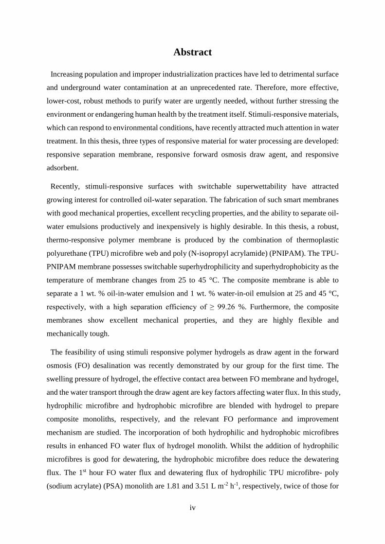
The feasibility of using stimuli responsive polymer hydrogels as draw agent in the forward
osmosis (FO) desalination was recently demonstrated by our group for the first time. The
swelling pressure of hydrogel, the effective contact area between FO membrane and hydrogel,
and the water transport through the draw agent are key factors affecting water flux. In this study,
hydrophilic microfibre and hydrophobic microfibre are blended with hydrogel to prepare
composite monoliths, respectively, and the relevant FO performance and improvement
mechanism are studied. The incorporation of both hydrophilic and hydrophobic microfibres
results in enhanced FO water flux of hydrogel monolith. Whilst the addition of hydrophilic
microfibres is good for dewatering, the hydrophobic microfibre does reduce the dewatering
flux. The 1st hour FO water flux and dewatering flux of hydrophilic TPU microfibre- poly
(sodium acrylate) (PSA) monolith are 1.81 and 3.51 L m-2 h-1, respectively, twice of those for
v
PSA particles. The water flux of PSA – hydrophobic polyester microfibre composite (PSA –
PET) reaches 5.0 LMH in the first 10 mins, twice as high as the relevant pure hydrogel alone.
Conversely, the dewatering flux of PSA-PET decreases to half of those of pure hydrogel. The
kinetic swelling studies show that the use of monolithic hydrogels and the addition of
hydrophilic microfibres enhance water diffusion through the draw agent and sustain high
swelling pressure, resulting in improved FO performance. On the other hand, the combination
of hydrophilic ionic hydrogel and hydrophobic PET microfibre produced pores in the
composite hydrogel because of different wettability, with an additional relaxation force
preserved in the composites because of the compressed pressure applied during the preparation.
Thus, the porous structure improves the water diffusion, while the compressed pressure
enhances the polymer chain relaxation rate.
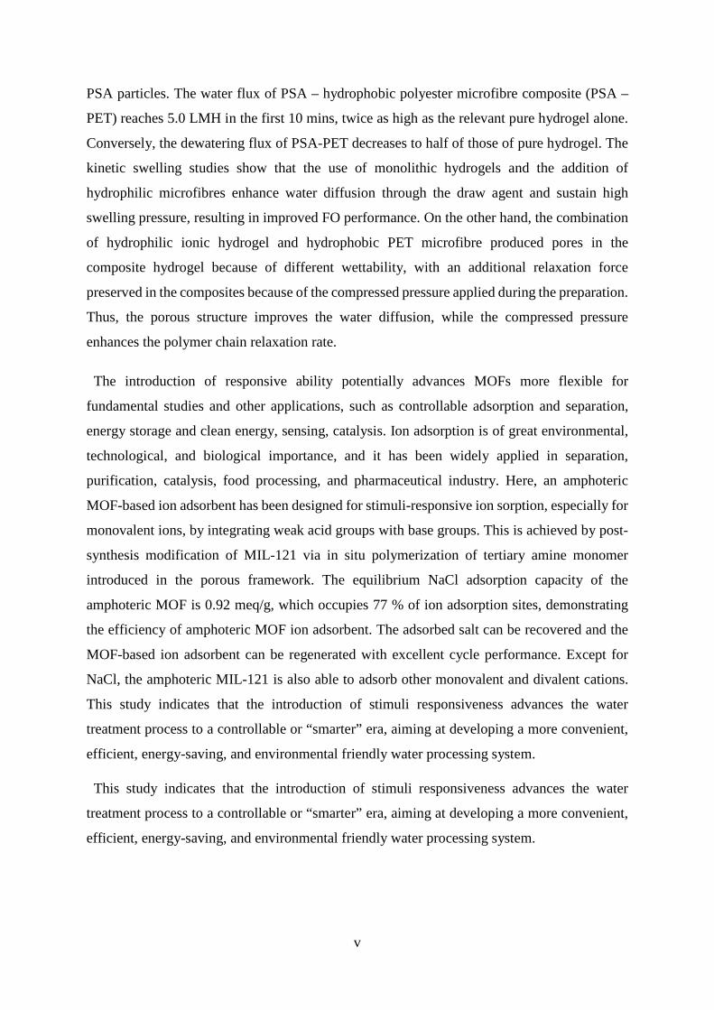
The introduction of responsive ability potentially advances MOFs more flexible for
fundamental studies and other applications, such as controllable adsorption and separation,
energy storage and clean energy, sensing, catalysis. Ion adsorption is of great environmental,
technological, and biological importance, and it has been widely applied in separation,
purification, catalysis, food processing, and pharmaceutical industry. Here, an amphoteric
MOF-based ion adsorbent has been designed for stimuli-responsive ion sorption, especially for
monovalent ions, by integrating weak acid groups with base groups. This is achieved by post-
synthesis modification of MIL-121 via in situ polymerization of tertiary amine monomer
introduced in the porous framework. The equilibrium NaCl adsorption capacity of the
amphoteric MOF is 0.92 meq/g, which occupies 77 % of ion adsorption sites, demonstrating
the efficiency of amphoteric MOF ion adsorbent. The adsorbed salt can be recovered and the
MOF-based ion adsorbent can be regenerated with excellent cycle performance. Except for
NaCl, the amphoteric MIL-121 is also able to adsorb other monovalent and divalent cations.
This study indicates that the introduction of stimuli responsiveness advances the water
treatment process to a controllable or “smarter” era, aiming at developing a more convenient,
efficient, energy-saving, and environmental friendly water processing system.
This study indicates that the introduction of stimuli responsiveness advances the water
treatment process to a controllable or “smarter” era, aiming at developing a more convenient,
efficient, energy-saving, and environmental friendly water processing system.
vi
List of Publications
Journal Publications:
[1] Ranwen Ou, Jing Wei, Lei Jiang, George P. Simon, and Huanting Wang, Robust
thermoresponsive polymer composite membrane with switchable superhydrophilicity and
superhydrophobicity for efficient oil-water separation. Environ. Sci. Technol. 2016, 50, 906-
914
[2] Ranwen Ou, Huacheng Zhang, George P. Simon, Huanting Wang, Microfibre-polymer
hydrogel monolith as forward osmosis draw agent. J. Membr. Sci. 2016, 510, 426-436
[3] Ranwen Ou, Huacheng Zhang, George P. Simon, Huanting Wang, Modification of
swelling property of ionic hydrogel for forward osmosis application, Ind. Eng. Chem. Res.,
2017, 56 (2), pp 505–512
[4] Ranwen Ou, Huacheng Zhang, Jing Wei, Li Wan, Yaoxin Hu, George P. Simon, and
Huanting Wang, Functionalized Metal Organic Framework with Thermoreversible Ion
Sorption Property for Efficient Water Desalination, to be submitted.
Oral Presentations:
[1] Ranwen Ou, Jing Wei, Huanting Wang, Hydrogel composite monolith as forward osmosis
draw agent, International Forward Osmosis Summit 2016, Sydney, Australia
[2] Ranwen Ou, Huacheng Zhang, George P. Simon, Huanting Wang, Hydrophilic microfibre-
polymer hydrogel monolith as forward osmosis draw agent, 9th International Membrane
Science and Technology Conference, Adelaide, Australia
Other Publications during PhD study:
[1] Ranwen Ou, Yaqin Wang, Huacheng Zhang, Huanting Wang, Tongwen Xu, Preparation
of high-flux ultrafiltration membranes by blending strongly charged polymer. J. Appl. Polym.
Sci. 2016, DOI: 10.1002/APP.44570
[2] Jing Wei, Ze-xian Low, Ranwen Ou, George P. Simon, Huanting Wang. Hydrogel-
polyurethane interpenetrating network material as an advanced draw agent for forward osmosis
process. Water Res. 2016, 96, 292-298.
vii
[3] Seungju Kim, Xiaocheng Lin, Ranwen Ou, Huiyuan Liu, Xiwang Zhang, George P. Simon,
Christopher D. Easton and Huanting Wang, Highly crosslinked, chlorine tolerant polymer
network entwined graphene oxide membrane for water desalination. J. Mater. Chem. A, 2017,
5, 1533-1540
[4] Huacheng Zhang, Ye Tian, Jue Hou, Xu Hou, Guanglei Hou, Ranwen Ou, Huanting Wang,
Lei Jiang, Bioinspired smart gate-location-controllable single nanochannels: experiment and
theoretical simulation. ACS Nano. 2015, 9 (12), 12264-12273
[5] Li Wan, Jing Wei, Yan Liang, Yaoxin Hu, Xiaofang Chen, Ezzatollah Shamsaei, Ranwen
Ou, Xiwang Zhang, Huanting Wang, ZIF-derived nitrogen-doped carbon / 3D graphene
frameworks for all-solid-state supercapacitors. RSC. Adv. 2016, 6, 76575-76581
viii
Table of Contents
Copyright Notices .................................................................................................................................... i
Declaration .............................................................................................................................................. ii
Acknowledgements ................................................................................................................................ iii
Abstract .................................................................................................................................................. iv
List of Publications ................................................................................................................................ vi
List of Figures ........................................................................................................................................ xi
List of Tables ....................................................................................................................................... xix
Chapter 1 Introduction ............................................................................................................................ 1
1.1 Research Background ................................................................................................................... 1
1.2 Research Aims .............................................................................................................................. 3
1.3 Thesis Overview ........................................................................................................................... 5
1.4 References ..................................................................................................................................... 8
Chapter 2 Literature Review ................................................................................................................. 10
2.1 Water Treatment ......................................................................................................................... 10
2.1.1 Water issue ........................................................................................................................... 10
2.1.2 Conventional water treatment system .................................................................................. 12
2.1.3 Advanced water treatment technologies .............................................................................. 14
2.2 Stimuli Responsive Polymeric Materials .................................................................................... 32
2.2.1 Type of responsive polymers ............................................................................................... 32
2.2.2 Applications ......................................................................................................................... 39
2.3 Responsive Materials for Water Treatment ................................................................................ 41
2.3.1 Responsive membrane ......................................................................................................... 41
2.3.2 Responsive draw agent ......................................................................................................... 51
2.3.3 Responsive adsorbent ........................................................................................................... 55
2.4 Summary ..................................................................................................................................... 58
2.5 References ................................................................................................................................... 59
Chapter 3 Robust thermo-responsive polymer composite membranes with switchable superhydrophilicity and superhydrophobicity for efficient oil-water separation .................................. 80
Overview ........................................................................................................................................... 80
3.1 Introduction ................................................................................................................................. 81
3.2 Experimental ............................................................................................................................... 84
3.2.1 Materials .............................................................................................................................. 84
3.2.2 Experimental procedures ...................................................................................................... 84
3.3 Results and Discussion ............................................................................................................... 86
3.3.1 Preparation and morphology ................................................................................................ 86
ix
3.3.2 Mechanical properties .......................................................................................................... 90
3.3.3 Wettability ............................................................................................................................ 92
3.3.4 Swelling behaviour .............................................................................................................. 95
3.3.5 Oil water separation capacity ............................................................................................... 96
3.4 Summary ................................................................................................................................... 102
3.5 References ................................................................................................................................. 103
Chapter 4 Microfibres-polymer hydrogel monolith as forward osmosis draw agent ......................... 107
Overview ......................................................................................................................................... 107
4.1 Introduction ............................................................................................................................... 108
4.2 Experimental ............................................................................................................................. 110
4.2.1 Materials ............................................................................................................................ 110
4.2.2 Experimental procedures .................................................................................................... 110
4.3 Results and discussion .............................................................................................................. 113
4.3.1 Morphology of composite hydrogels ................................................................................. 113
4.3.2 Swelling properties of hydrogels ....................................................................................... 113
4.3.3 Water diffusion in composite hydrogels ............................................................................ 116
4.3.4 Forward osmosis performance of hydrogels ...................................................................... 117
4.3.5 Swelling mechanism of hydrogels ..................................................................................... 127
4.4 Summary ................................................................................................................................... 128
4.5 References ................................................................................................................................. 128
Chapter 5 Improvement of the swelling properties of ionic hydrogels by the incorporation of hydrophobic, elastic microfibres for forward osmosis applications ................................................... 132
Overview ......................................................................................................................................... 132
5.1 Introduction ............................................................................................................................... 133
5.2 Experimental ............................................................................................................................. 135
5.2.1 Materials ............................................................................................................................ 135
5.2.2 Experimental Procedures ................................................................................................... 135
5.3 Results and Discussion ............................................................................................................. 138
5.3.1 Morphology of PET-hydrogel composites ......................................................................... 138
5.3.2 Swelling behaviour of hydrogels ....................................................................................... 140
5.3.3 Forward osmosis and dewatering performance .................................................................. 145
5.3.4 Effect of hydrophilic or hydrophobic fibres on FO performance of hydrogels ................. 147
5.4 Summary ................................................................................................................................... 150
5.5 References ................................................................................................................................. 151
Chapter 6 Functionalized Metal Organic Framework with thermoreversible ion sorption property for efficient water desalination ................................................................................................................. 153
Overview ......................................................................................................................................... 153
6.1 Introduction ............................................................................................................................... 154
x
6.2 Experimental ............................................................................................................................. 156
6.2.1 Materials ............................................................................................................................ 156
6.2.2 Experimental Procedures ................................................................................................... 156
6.3 Results and Discussion ............................................................................................................. 158
6.3.1 Modification of amphoteric MOFs .................................................................................... 158
6.3.2 Morphology salt adsorption of MOFs ................................................................................ 161
6.3.3 Adsorption and thermal desorption mechanisms ............................................................... 162
6.3.4 NaCl adsorption capacity of amphoteric MOFs ................................................................. 164
6.3.5 Cycling performance of amphoteric MOFs ....................................................................... 165
6.3.6 Adsorption of other ions .................................................................................................... 166
6.4 Summary ................................................................................................................................... 168
6.5 References ................................................................................................................................. 168
Chapter 7 Conclusion and Future Work ............................................................................................. 173
7.1 Conclusion ................................................................................................................................ 173
7.2 Further Directions ..................................................................................................................... 175

xi
List of Figures
Chapter 2
2.1 World map of water withdrawal and consumption and sanitation accessibility................10
2.2 Schematic illustration of conventional water treatment process........................................12
2.3 Traditional (chlorine) and advanced oxidation process and number of AOP publications
over 1975-2000 period.....................................................................................................16
2.4 Illustration of different membrane filtration processes......................................................28
2.5 Scheme of membrane filtration..........................................................................................28
2.6 Illustration of reverse osmosis and forward osmosis process............................................31
2.7 Definition of responsive polymeric materials....................................................................32
2.8 Chemical structures of LCST polymers.............................................................................33
2.9 Chemical structures of moieties for synthesis of photo-responsive polymers...................35
2.10 Several applications of stimuli responsive material.........................................................40
2.11 A schematic representation of the thermo-responsive release principle of core-shell
microcapsules with a porous membrane and thermo-responsive PNIPAM gates...........45
2.12 The extended and contracted state of porous and bulk nonporous responsive membrane
and their permeation upon solutes....................................................................................46
2.13 Controllable oil water separation using pH responsive membrane..................................48
2.14 Alternative temperature change cleaning procedures of raw ZrO2 and PNIPAM-g-ZrO2
membrane.........................................................................................................................50
2.15 Schematic illustration of forward osmosis desalination process......................................51
2.16 Quasi-continuous FO desalination using a semi-IPN hydrogel as the draw agent...........54
Chapter 3
3.1 Schematic illustration of robust thermo-responsive composite membrane.........................80
xii
3.2 The preparation process of TPU microfibre mat by a force spinner..................................85
3.3 (a) The preparation process of a TPU-PNIPAM composite membrane. The TPU microfibre
membrane immersed with NIPAM reaction solution (16.7 wt. %) is polymerized at 70 °C
for 2 hours. Photographs of twisting test of (b) TPU microfibre membrane and (c) TPU-
PNIPAM membrane with 3.6 wt. % PNIPAM loading (TPU-PNIPAM-3.6). (d) Stress-
strain curves of TPU microfibre membrane and swollen TPU-PNIPAM-3.6
membrane.........................................................................................................................86
3.4 Contact angle-time curves of TPU film with DDI water and NIPAM solution (16.67 wt. %)
as testing medium.............................................................................................................87
3.5 Schematic diagram of formation of TPU-PNIPAM composite. (a) Free radical
polymerization of PNIPAM hydrogel, (b) basic chemistry of TPU, (c) polymerization of
PNIPAM hydrogel on the TPU microfibre’s surface. The hydrogen bonds formed between
urethane groups and acrylamide groups combined two polymers.....................................87
3.6 (a) SEM image and (b) diameter distribution of TPU microfibre membrane.......................88
3.7 SEM images of TPU microfibre membrane and TPU-PNIPAM composite membranes (3.6
and 13.4 wt. %). Membrane surfaces of (a) TPU microfibre membrane (558×), (b) TPU-
PNIPAM-3.6 (811×) and (c) TPU-PNIPAM-13.4 membrane (683×); microfibre surfaces
of (d) TPU microfibres (71202×), (e) TPU-PNIPAM-3.6 (67286×) and (f) TPU-PNIPAM-
13.4 (35187×); microfibre cross-sections of (g) TPU microfibres (38448×), (h) TPU-
PNIPAM-3.6 (43471×) and (i) TPU-PNIPAM-13.4 (2885×) ........................................88
3.8 (a) SEM image and (b) pore size distribution of composite membrane with 3.6 wt. %
PNIPAM (TPU-PNIPAM-3.6), and (c) SEM image and (d) pore size distribution of TPU-
PNIPAM-13.4 membrane.................................................................................................89
3.9 Membrane thickness and PNIPAM coating thickness of composite membranes (1.4, 3.6,
7.6, 13.4, and 25.3 wt. %)..................................................................................................90
3.10 (a) elongation, (b) tensile strength, (c) Young’s modulus, and (d) toughness of TPU
microfibre membrane (0 wt. %) and TPU-PNIPAM membranes (1.4, 3.6, 7.6, 13.4, and
25.3 wt. %)........................................................................................................................91
3.11 Water contact angle images of (a) TPU film and (b) TPU microfibre membrane...........92
xiii
3.12 (a) Water contact angles of swollen TPU-PNIPAM membranes (1.4, 3.6, 7.6, 13.4, and
25.3 wt. %) and the swollen PNIPAM hydrogel (100 wt. %) at room temperature (RT)
and 45°C. (b) Schematic diagram of switching wettability of TPU-PNIPAM membrane at
different temperatures. (c) A water droplet (1µL) spreading on a swollen TPU-PNIPAM-
3.6 membrane within 0.094 s at room temperature. (d) Water contact angle (150.2°) of
swollen TPU-PNIPAM-3.6 membrane at 45 °C. (e) Underwater oil contact angle (141.3°)
of swollen TPU-PNIPAM-3.6 membrane at room temperature. (f) Underwater oil contact
angle of swollen TPU-PNIPAM-3.6 membrane at 45°C. Hexadecane was used for testing
the underwater oil contact angle........................................................................................93
3.13 SEM images of composite membranes and the relevant water contact angle. (a) TPU-
PNIPAM-1.4, (b) TPU-PNIPAM-3.6, (c) TPU-PNIPAM-7.6, (d) TPU-PNIPAM-13.4, (e)
TPU-PNIPAM-25.3. (f) Water contact angle of composite membranes and PNIPAM
hydrogel at room temperature and 45 °C.........................................................................94
3.14 Photographs of TPU-PNIPAM-3.6 immersed into DDI water at different temperatures:
(a) room temperature, (b) 45 °C.......................................................................................94
3.15 Swelling properties of the PNIPAM of TPU-PNIPAM-3.6 membrane. (a) Swelling curve
of dry TPU-PNIPAM-3.6 membrane. (b) Swelling ratio of TPU-PNIPAM-3.6 membrane
at different temperatures. (c) Deswelling curve of TPU-PNIPAM-3.6 membrane tested at
45 °C DDI water. (d) Reswelling curve of TPU-PNIPAM-3.6 membrane tested at 25°C
DDI water.........................................................................................................................95
3.16 (a) Oil intrusion pressure and water flux of TPU-PNIPAM membranes (1.4, 3.6, 7.6, 13.4,
and 25.3 wt. %) at room temperature. (b) Water intrusion pressure and oil flux of TPU
microfibre membrane and TPU-PNIPAM membranes at 45 °C. Hexadecane was used as
the test oil. (c) Separation efficiency of TPU-PNIPAM-3.6 membrane for reversibly oil-
water separation at room temperature and 45 °C. The inset shows the 1 wt. % SDS-
stabilized silicone oil-water emulsion and the collected water before and after separation
at room temperature (left), and the 99 wt. % SDS-stabilized silicone oil-water emulsion
and the collected oil before and after separation at 45 °C (right). (d) Separation efficiencies
of TPU-PNIPAM-3.6 membrane for separating different 1 wt. % oil-water emulsions at
room temperature..............................................................................................................97
xiv
3.17 Controllable oil-water separation using TPU-PNIPAM-3.6 membrane at (a) room
temperature and (b) 45 °C respectively (hexadecane: red, water: transparent)................98
3.18 (a) The variation of flux as a function of time for 24 h separation of 1 wt. % SDS –
stabilized hexadecane-water emulsion. (b) The variation of flux as a function of time for
24 h separation of 99 wt. % SDS-stabilized hexadecane-water emulsion. TPU-PNIPAM-
3.6 was used in the test of (a) and (b)...............................................................................98
3.19 Optical microscopy images and diameter distribution of oil drops in 1 wt. % oil-water
emulsion and water drops in 99 wt. % oil-water emulsion............................................100
3.20 Optical microscopy images SDS-stabilized 1 wt. % oil-water emulsions before (a1-e1)
and after (a2-e2) filtration..............................................................................................101
3.21 Optical microscopy images SDS-stabilized 99 wt. % oil-water emulsions before (a1-b1)
and after (a2-b2) filtration..............................................................................................102
Chapter 4
4.1 Schematic illustration of water transport in TPU-hydrogel composite..............................107
4.2 The preparation process of TPU-hydrogel composites......................................................111
4.3 Water flux of PN5S5 hydrogel particle and PN5S5 composite hydrogels with different TPU
loadings..........................................................................................................................111
4.4 SEM images of TPU microfibres and cross-section of composite hydrogels....................113
4.5 Swelling ratios of pure hydrogel and composite hydrogels...............................................114
4.6 (a) Swelling behavior and (b) swelling kinetics of pure hydrogel (PN5S5) and composite
hydrogel (TPU-PN5S5) .................................................................................................115
4.7 Wettability of TPU microfibres and water absorption ability of hydrogels....................116
4.8 (a) The swelling of pure hydrogel (left) and composite hydrogel (right) in aqueous
rhodamine B (RhB) solution. (b) The water absorption process of composite hydrogel (50
wt. % water content) tracked by rhodamine B aqueous solution. These images were taken
with an optical microscope.............................................................................................117
4.9 One hour FO water flux of pure hydrogel particle and composite hydrogels..................118
xv
4.10 SEM images of pure hydrogel particles.........................................................................119
4.11 The first 10 min FO water fluxes of PSA particle and wet TPU-PSA composite, with 2000
ppm NaCl solution or pure water as feed.........................................................................120
4.12 24 hours forward osmosis water flux of (a) pure hydrogel particle and (b) composite
hydrogels with 50 wt. % initial water content; average dewatering flux of (c) pure
hydrogel particle and (d) composite hydrogels as a function of SA content.................122
4.13 Forward osmosis and solar dewatering performance of pure hydrogel particle and
composite hydrogels ......................................................................................................123
4.14 Liquid and vapour water recovery of hydrogels in the dewatering process...................124
4.15 Temperature changes of (a) pure hydrogel particle and (b) composite hydrogels under a 1
kW·m-2 incandescent heat dewatering process...............................................................124
4.16 Reusability of (a) PSA particles and (b) TPU-PSA. 5 cycles of forward osmosis and
dewatering performance were tested..............................................................................125
4.17 The swelling ratio of PSA and TPU-PSA under different osmotic pressure (different
concentration of NaCl solution) ....................................................................................126
4.18 The proposed swelling mechanisms of (a) pure hydrogel particle and (b) TPU-hydrogel
composite.......................................................................................................................127
Chapter 5
5.1 Illustration of the swelling pressure improvement of PET-hydrogel composite..............132
5.2 The preparation process of hydrogel-PET microfibre composite....................................137
5.3 The solar dewatering setup for measuring the liquid water recovery..............................138
5.4 SEM images of (a) PN5S5 hydrogel and (b) PET microfibres........................................139
5.5 (a-c) Surface and (d-f) cross-sectional SEM images of composite hydrogels.................139
5.6 (a) Swelling ratio and (b) swelling kinetics of hydrogels with different loadings of PET
microfibres, and (c) forward osmosis water flux induced by the hydrogel and its
composites......................................................................................................................141
xvi
5.7 The optical images of pure PN5S5 hydrogel and PN5S5-PET-0.5/0.5 composite hydrogel
(a) before and (b) after swelling in aqueous rhodamine B (RhB) solution....................142
5.8 (a) Swelling ratio and (b) swelling kinetics of PN5S5-PET-0.5/0.5 hydrogels prepared with
different compression pressure, and (c) forward osmosis water flux induced by the
hydrogel draw agent.......................................................................................................143
5.9 The 60 mins forward osmosis water flux of PSA composite with (a) different PET fibres
loading, and (b) different compressed pressure loading................................................144
5.10 Plot of swelling ratio of PN5S5 and PN5S5-PET-0.5/0.5-18 as a function of osmotic
pressure of NaCl solution at equilibrium.........................................................................144
5.11 (a) 24 hours FO water flux, and (b) dewatering performance of hydrogels...................145
5.12 The temperature change of pure hydrogel and composite hydrogel during 60 mins solar
dewatering under 1 kW/m2 incandescent lamp..............................................................146
5.13 The cycle performance of PN5S5-PET-0.5/0.5-18 composite.......................................146
5.14 SEM images of (a) PET microfibre and (b) polydopamine coated PET microfibre.........147
5.15 Wettability of PET microfibre, polydopamine coated PET microfibre and their composite
hydrogels........................................................................................................................147
5.16 Contact angle of PET (a, c) and D-PET (b, d) microfibres with NIPAM solution (a, b) and
SA solution (c, d) as testing medium...............................................................................148
5.17 Optical images of (a, b) PN5S5-PET and (c, d) PN5S5-D-PET hydrogel before and after
dropping a drop of 100 ppm RhB solution.....................................................................149
5.18 (a) Forward osmosis water flux and (b) dewatering performance of PN5S5-PET-0.5/0.5-
18 and PN5S5-D-PET-0.5/0.5-18...................................................................................149
Chapter 6
6.1 Illustration of reversible ion sorption with functionalized MOF.......................................153
6.2 Schematic illustration of the synthesis of amphoteric-functionalized MIL-121 (PDMVBA-
p-MIL-121) and its thermoreversible adsorption process...............................................155
xvii
6.3 The SEM images of MIL-121 crystals calcined at different temperatures.........................158
6.4 FTIR spectra of MIL-121 powder calcined at different temperatures................................159
6.5 XRD patterns of MIL-121 powders calcined at different temperatures.............................159
6.6 The adsorption capacity (1000 ppm NaCl solution) of PDMVBA-p-MIL-121 prepared with
MIL-121 powders calcined at different temperatures, and 3 days of impregnation time
before polymerization.....................................................................................................160
6.7 The adsorption capacity (1000 ppm NaCl solution) of PDMVBA-p-MIL-121 prepared with
different impregnation time before polymerization and MIL-121-300°C.......................160
6.8 TEM images of (a) as-prepared MIL-121-300 °C and (b) after kept in water udner stirring
for one month.................................................................................................................160
6.9 Characterization of MIL-121 and PDMVBA-p-MIL-121. SEM images of (a) MIL-121-300
°C and (b) PDMVBA-p-MIL-121. (c) NaCl adsorption capacity of PDMVBA, MIL-121-
300°C and PDMVBA-p-MIL-121. (d) XRD patterns of as-prepared MIL-121, MIL-121-
300 °C, and PDMVBA-p-MIL-121 before and after NaCl adsorption. The red arrows on
the peaks show the peak shift of pattern MIL-121-300 °C compared with the XRD pattern
of MIL-121. (e) FTIR spectra of MIL-121-300 °C, and PDMVBA-p-MIL-121 before and
after NaCl adsorption......................................................................................................161
6.10 The MgCl2 adsorption capacity of PDMVBA, MIL-121-300°C and PDMVBA-p-MIL-
121..................................................................................................................................162
6.11 Thermogravimetric analysis curves and the relevant derivative of (a) MIL-121, (b) MIL-
121-300°C, (c) PDMVBA-p-MIL-121-300°C, and (d) PDMVBA-p-MIL-121-300°C-
NaCl. The TGA was conducted under N2 gas flow.......................................................162
6.12 The adsorption capacity of PDMVBA-p-MIL-121 at different NaCl concentrations...165
6.13 a) The cycling performance of PDMVBA-p-MIL-121 for thermoreversible sorption of
10000 ppm NaCl solution. The PDMVBA-p-MIL-121 was thermally regenerated at 80
°C in 500 ppm NaCl solution. b) FTIR spectra of PDMVBA-p-MIL-121 before and after
NaCl adsorption, and after thermal desorption................................................................165
xviii
6.14 The FTIR spectra of PDMVBA-p-MIL-121 before and after the adsorption of NaCl, and
after thermal regeneration..............................................................................................166
6.15. The adsorption capacity of PDMVBA-p-MIL-121 for adsorption of different monovalent
and divalent cations........................................................................................................166
xix
List of Tables
Chapter 2
2.1 Redox potential of oxidants................................................................................................15
2.2 Specific surface area and applications of adsorbents.........................................................21
Chapter 3
3.1 Superwetting membranes and relevant properties for oil-water separation published in
recent years.......................................................................................................................82
Chapter 4
4.1 Composition of pure hydrogels and composite hydrogels...............................................110
4.2. The water flux of hydrogel draw agent in recent publications........................................121
Chapter 5
5.1 Composition of pure hydrogel and composite hydrogels.................................................136
Chapter 6
6.1 The radius, hydration energy, and solubility of relevant benzoic acid salt of cations.....167

xx
Chapter 1 Introduction
1
Chapter 1 Introduction
1.1 Research Background
Some 97 % of water on earth exists as ocean saltwater, 0.5 % is brackish water found in
surface estuaries and salty underground aquifers, whilst fresh water only constitutes 2.5%. Of
this freshwater, less than one percent is usable by humans, because most freshwater is locked
into polar icecaps or permanent mountain snow cover.[1] It is estimated that 1.2 billion people
lack access to safe drinking water, 2.6 billion have little or no sanitation, and millions of people
die annually-3,900 children a day-from severe waterborne diseases.[2] However, increasing
population and poor industrialization practices have led to detrimental surface and underground
water contamination at an unprecedented rate, worsening this situation. Much effort has been
made into the purification of contaminated water, since the total amount of usable freshwater
is limited. Even though conventional water treatment methods can address many of these
problems, they are often chemically, energetically and operationally intensive. The chemicals
used in the treatment will become the contamination sources of freshwater. In addition,
developing a conventional water and wastewater treatment facility require considerable
infusion of capital and time, which precludes their use in much of the world, especially where
water is really needed.[3] More effective, lower-cost, robust methods to purify water are
urgently needed, without further stressing the environment or endangering human health by
the treatment itself.
Advanced water treatment technology has been developed to deal with this problems. In the
past several decades, advanced oxidation process, biological treatment, adsorption / ion
exchange process and membrane separation process have attracted intensive attention, and
proven to be suitable for practical application.
Advanced oxidation processes (AOPs) deal with the chemically polluted water and
wastewater, and has shown great potential for the treatment of ground water, municipal
wastewater sludge and volatile organic compounds (VOCs).[4, 5] AOPs are also capable of
treating problematic pollutants in water that may not be removed by conventional treatment
method effectively, such as persistent organic pollutants, which is toxic, stable and active in
the environment. The AOP aims to mineralize the organic pollutant into relatively harmless
inorganic molecules, such as carbon dioxide, water, sulphates and nitrate.[6] Biological
treatment has been used for consuming biodegradable soluble organic contaminants and
Chapter 1 Introduction
2
removal of nitrogen and phosphorus in the conventional wastewater treatment system.[7] The
practical value of biological water treatment technologies arise for several reasons. Firstly, this
process is operationally practical, it can be carried out in situ at the polluted site. Secondly, it
is an environmentally friendly technology, without generating secondary pollution. Thirdly, it
is cost-effective. The recent development of this utilized technology is concentrated on removal
of metal ions and oils.
Membrane filtration has proven to be one of the most promising separation techniques.[8]
Membrane separation processes, like microfiltration, ultrafiltration, nanoflitration, reverse
osmosis, in water treatment have increased rapidly over the past decade.[9] Microfiltration and
ultrafiltration process are widely used in food and beverage processing, biotechnological
applications and pharmaceutical industry, water purification and others. [10-12] Nanofiltration
and reverse osmosis process are mainly used for water purification. [13, 14] Seawater reverse
osmosis (SWRO) plants have been built to undertake seawater desalination to alleviate the
water scarcity problem, even though they are energy-intensive. Low-pressure driven membrane
processes (microfiltration / ultrafiltration) are highly promising due to their relatively low
energy consumption. Forward osmosis (FO), which has been widely investigated for
desalination and wastewater treatment, is renowned for little or no operation pressures, high
rejection over a wide range of contaminants and lower membrane fouling propensity than
pressure-driven membrane processes.[15] Compared to the traditional water treatment methods,
membrane filtration technique has the following advantages: (1) it is a simple, low capital cost,
low-maintenance process; (2) the systems are compact, and some of them are portable;
ultrafiltration setup can be connected to the tap to purify the tap water; (3) it is an
environmentally-friendly process, without the need for addition of chemicals during the
treatment.
Adsorption is of great environmental, technological, and biological importance, as often
stressed. Generally, porous solid materials are used as adsorbent for gas-phase and liquid-phase
adsorption, e.g. active carbons, metal oxides, zeolites, clays, and metal organic framework.[16]
Adsorption at the liquid/solid interface is of great importance in industry and everyday life,
such as in detergents, adhesion, lubrication, flotation of minerals, water treatment, oil recovery,
pigments and particle technology. To efficiently decontaminate aqueous wastes, both
adsorption and ion exchange are considered to be highly effective and affordable/low-cost
methods.
Chapter 1 Introduction
3
“Smart” or responsive polymer materials respond to surrounding environments by changing
their physicochemical properties, such as regulating transport of ions and molecules, changing
wettability and adhesion of different species on external stimuli, or converting chemical and
biochemical signals into optical, electrical, thermal and mechanical signals, and vice versa.[17]
In addition to the fundamental interest, responsive materials are playing an increasing
important role in a variety of applications, such as drug delivery, tissue engineering, biosensors,
coatings, as well as the emerging environmental applications.[18] The introduction of a
responsive ability or “smartness” endows a designated material or device with multiple
synergistic and advanced functions, broaden its applications and promote its performance.
With the rapid development of responsive polymer materials, smart systems have been
incorporated with the filtration system for separation and purification purposes, responsive
membrane, responsive draw agent and responsive adsorbent have emerged, and gaining
increasing concern in the recent decades. The occurrence of smart membrane have realized the
controllable separation process, and bridged to anti-fouling membrane and biomimetic
membrane. Smart draw agent, which can recover the water with low energy cost, lights the
future of forward osmosis desalination process. The responsive adsorbent that can be
regenerated and recycled by stimuli, especially physical stimuli, is ideal for resource
reclamation from contaminated water or water softening. The smart filtration system with self-
cleaning, self-refreshing, energy-saving, or controllable separation abilities will improve the
efficiency of many technological processes, and has strong potential for future applications.
1.2 Research Aims
Responsive membrane systems with switchable properties and highly adaptive surfaces have
been manufactured in recent decades, but most have been focused on how different responsive
interactions within the membranes can be tuned and monitored in controlled environments,
such as permeation and pore size. The challenges of responsive membrane for water treatment
lie in: (1) how to achieve functionality while maintaining membrane stability and mechanical
integrity for the practical application; (2) how to fabricate a membrane which can respond in
more complex and less defined situations and mimic the functionalities of living systems. It is
thought that responsive membranes will be used in various niche applications in the next 5-10
years, and be more widely use in 10-20 years.[19] It is a challenge, yet highly desirable to
explore the field of responsive membrane with better properties and practical applications.

Chapter 1 Introduction
4
Meanwhile, only a few responsive materials have been investigated as draw agents, including
magnetic particles, responsive polyelectrolyte and hydrogel. Responsive hydrogels, which
shows great potential for practical application, have been developed by our group.[20, 21]
Using responsive FO draw agent shows several advantages, such as the ready recovery of
product water and draw agent, and low back diffusion. However, there are still some challenges
upon the applications of responsive draw agent: 1) relatively low water flux, 2) incomplete
theoretical study, 3) reusability, 4) development of proper FO unit for continuous water
production.
Responsive adsorbents have been intensively studied in the past several decades, primarily
magnetic responsive adsorbent for easy collection and separation from aqueous solution. Other
responsive materials introduced are mainly used to tune the wettability and adhesion of
different species for the selective adsorption purpose. The regeneration of adsorbent by stimuli
responsiveness can significantly reduce the cost of adsorption process, but investigates rarely.
The development of stimuli-responsively regenerable adsorbent with high adsorption and
proper reusability is highly desirable.
The development of practical responsive forward osmosis draw agents, responsive separation
membranes and responsive adsorbent is thus still at an early stage.
The research aim of this study is to introduce stimuli responsive ability into the water
treatment system, and analyze the effect of responsiveness on the performance of the material
and process, aiming to improve the performance and understand the improvement mechanisms.
More specifically,
1. Development of high efficiency separation membranes for water treatment
(1) Introducing responsiveness to a membrane/film by incorporating responsive polymer;
(2) Introducing special wettability into the responsive composite membrane for novel
properties;
(3) Improving the separation performance of responsive membrane;
(4) Improving the response rate of the responsive membrane;
(5) Investigating the relationship between surface roughness, special wettability, novel
properties, and the performance of the membrane.
2. Development of high-performance smart draw agents for forward osmosis processes
Chapter 1 Introduction
5
(1) Introducing special wettability into the smart composite hydrogel for novel properties;
(2) Improving the water absorbing ability and stimuli response rate of the draw agent;
(3) Improving the liquid transportation inside the responsive draw agent;
(4) Investigating the relationship between roughness, special wettability, novel properties, and
the forward osmosis performance of the draw agent.
(5) Investigating the improvement mechanisms by studying swelling behavior.
3. Development of responsive adsorbent for efficient solute removal
(1) Selection of high surface area materials as the base;
(2) Introduce stimuli-responsiveness into the highly porous material for reversible adsorption
and desorption;
(3) Improving the adsorption performance and kinetics of the responsive adsorbent;
(4) Investigating the solute adsorbed and desorbed ability of this adsorbent;
(5) Study the mechanism of reversible adsorption and desorption theoretically.
1.3 Thesis Overview
Abstract
The brief background, research aims, and major findings of this thesis are concluded in this
section.
Chapter 1. Introduction
This section gives brief background on water treatment and responsive materials, research
aims and thesis overview.
Chapter 2. Literature Review
This chapter starts with emphasizing the importance of water treatment by summarizing the
current water issue. Traditional and recent water treatment technologies are detailed. Thirdly,
the responsive materials and responsive water treatment system are described. Finally, the
research aims and significance of this work are presented.
Chapter 3. Robust Thermo-responsive polymer composite membrane with switchable
superhydrophilicity and superhydrophobicity for efficient oil-water separation
Chapter 1 Introduction
6
In this work, a robust, thermo-responsive polymer membrane is produced by the combination
of an elastic polyurethane (TPU) microfibre web and poly (N-isopropyl acrylamide)
(PNIPAM). PNIPAM hydrogel is evenly coated on the surface of TPU microfibres, and thus,
the wettability of TPU-PNIPAM membrane is amplified by taking advantage of the
hierarchical structure and increased surface roughness. The TPU-PNIPAM membrane
possesses switchable superhydrophilicity and superhydrophobicity as the temperature of
membrane changes from 25 to 45 °C. The composite membrane is shown successfully able to
separate a 1 wt % oil-in-water emulsion and 1 wt % water-in-oil emulsion at 25 and 45 °C,
respectively, with a high separation efficiency of ≥99.26%. Furthermore, the composite
membranes show excellent mechanical properties, and they are highly flexible and
mechanically tough. The smart composite membranes reported here have great potential for
further development for practical high efficiency oil−water separations.
This chapter has been published as a journal article: Ranwen Ou, Jing Wei, Lei Jiang,
George P. Simon, and Huanting Wang, Environ. Sci. Technol. 2016, 50, 906-914
Chapter 4. Microfibre-polymer hydrogel monolith as forward osmosis draw agent
Stimuli-responsive polymer hydrogels have shown great potential for use as draw agent in
emerging forward osmosis (FO) technology. The swelling pressure of hydrogel and the
effective contact area between FO membrane and hydrogel are key parameters for achieving
such a high water flux. In this work, the forward osmosis performance of hydrogels can be
significantly improved by producing composite hydrogel monoliths containing thermoplastic
polyurethane (TPU) microfibres. The use of monolithic hydrogels and the addition of
microfibres enhance water diffusion through the draw agent and sustain high swelling pressure,
resulting in improved FO performance. As observed in the sigmoidal swelling curves, the
swelling kinetics of microfibre-hydrogel composite (TPU microfibre-poly (NIPAM-co—SA),
TPU-PN5S5) is faster than that of pure hydrogel (PN5S5), and the time required for the
composite to reach swelling equilibrium decreases significantly; the diffusion exponent of
TPU-PN5S5 composite increase from 0.73 to 0.81, indicating that addition of microfibres
increases the water diffusion rate. Further studies show that water transports more quickly
through the microchannels around TPU microfibres due to their hydrophilicity and capillary
forces. The composite monolith was tested as forward osmosis draw agent, and it was found
that the 1st hour FO water flux and dewatering flux of TPU-PSA are 1.81 and 3.51 L m-2 h-1,
respectively, twice of those for PSA particles alone.

Chapter 1 Introduction
7
This chapter has been published as a journal article: Ranwen Ou, Huacheng Zhang, George P.
Simon, Huanting Wang, J. Membr. Sci. 2016, 510, 426-436
Chapter 5. Modification of the swelling properties of ionic hydrogel for forward osmosis
applications
The swelling properties of hydrogels, and the effective contact between forward osmosis
membrane and hydrogel, are key parameters for improving the performance of a draw agent.
A new strategy is developed here to modify the swelling property of hydrogel by the
introduction of structural inhomogeneity and preservation of a compressed pressure in an ionic
hydrogel, in order to get increased forward osmosis water flux. That is achieved by the
incorporation of an ionic hydrogel with a hydrophobic microfibre under compressed pressure
during preparation. The forward osmosis water flux of the composite hydrogels generally
increased with increasing microfibre loading and compressed loading. The water flux of poly
(NIPAM-co-SA) – polyester microfibre composite (PN5S5 – PET) and poly (sodium acrylate)
– polyester microfibre composite (PSA – PET) reached 3.0 and 5.0 LMH in the first 10 mins,
respectively, when their swelling ratio is 4. The water flux of composites were twice as high
as the relevant, neat hydrogel. The composite hydrogels were also good at maintaining high
water flux over long time periods. The water flux of PSA-PET decreased from 3.5 to 1.4 LMH
after 24 hour forward osmosis test.
This chapter has been published as a journal article: Ranwen Ou, Huacheng Zhang, George
P. Simon, Huanting Wang, Ind. Eng. Chem. Res., 2017, 56 (2), pp 505–512
Chapter 6. Amphoteric Functionalized Metal Organic Framework for Highly Efficient,
Reversible Ion Sorption
To explore the emerging stimuli responsive MOFs for advanced adsorption technology, an
amphoteric MOF-based ion adsorbent is developed for physical stimuli reversible ion sorption,
especially for monovalent ions, by integrating cation sites and anion sites with responsiveness
in MOFs. This is illustrated by post-synthesis modification of MIL-121 via in situ
polymerization of tertiary amine monomer introduced in the framework. The synergic effect
of tertiary amine groups of the polymer and non-coordinating carboxylic acid groups of MIL-
121 give rise to the ion adsorption ability and thermal regeneration properties. The equilibrium
NaCl adsorption capacity of the amphoteric MOF is 0.92 meq/g, which occupies 77 % of ion
adsorption sites, demonstrating the efficiency of amphoteric MOF ion adsorbent. The adsorbed
Chapter 1 Introduction
8
salt can be recovered and the MOF-based ion adsorbent regenerated by heating at elevated
temperature in 500 ppm NaCl solution, with excellent cycle performance. Other than for NaCl,
the amphoteric MIL-121 is able to adsorb other monovalent and divalent cations. This study
firstly introduces an amphoteric MOF for monovalent ion adsorption, and realizes the thermal
regeneration of MOF-based ion adsorbent.
The results presented in this Chapter has been drafted and will be submit as a journal article:
Ranwen Ou, Huacheng Zhang, Jing Wei, Li Wan, Yaoxin Hu, George P. Simon, and Huanting
Wang, Functionalized Metal Organic Framework with Thermoreversible Ion Sorption Property
for Efficient Water Desalination.
Chapter 7. Conclusion and Future Work
This chapter concludes the major finding of this thesis and the suggest Future Work for stimuli
responsive materials in water processing.
1.4 References
[1] S. Diop, P. M'mayi, D. Lisbjerg, R. Johnstone, Vital water graphics: an overview of the
state of the world's fresh and marine waters, UNEP/Earthprint, 2002.
[2] M.A. Montgomery, M. Elimelech, Water and sanitation in developing countries:
including health in the equation, Environmental Science & Technology, 41 (2007) 17-24.
[3] M.A. Shannon, P.W. Bohn, M. Elimelech, J.G. Georgiadis, B.J. Mariñas, A.M. Mayes,
Science and technology for water purification in the coming decades, Nature, 452 (2008)
301-310.
[4] S. Parsons, Advanced oxidation processes for water and wastewater treatment, IWA
publishing, 2004.
[5] R. Andreozzi, V. Caprio, A. Insola, R. Marotta, Advanced oxidation processes (AOP) for
water purification and recovery, Catalysis today, 53 (1999) 51-59.
[6] D.G. Rao, R. Senthilkumar, J.A. Byrne, S. Feroz, Wastewater treatment: advanced
processes and technologies, CRC Press, 2012.
[7] Z. Aksu, Application of biosorption for the removal of organic pollutants: a review,
Process Biochemistry, 40 (2005) 997-1026.
[8] H. Bai, Z. Liu, D.D. Sun, A hierarchically structured and multifunctional membrane for
water treatment, Applied Catalysis B: Environmental, 111 (2012) 571-577.
Chapter 1 Introduction
9
[9] J. Mulder, Basic principles of membrane technology, Springer Science & Business Media,
2012.
[10] L.J. Zeman, A.L. Zydney, Microfiltration and ultrafiltration: principles and applications,
M. Dekker, 1996.
[11] J.K. Bungay, P.M. Bungay, H. Lonsdale, M. de Pinho, Synthetic Membranes:: Science,
Engineering and Applications, Springer Science & Business Media, 2012.
[12] V. Goel, M.A. Accomazzo, A.J. DiLeo, P. Meier, A. Pitt, M. Pluskal, R. Kaiser,
Deadend microfiltration: applications, design, and cost, in: Membrane Handbook, Springer,
1992, pp. 506-570.
[13] B. Van der Bruggen, C. Vandecasteele, Removal of pollutants from surface water and
groundwater by nanofiltration: overview of possible applications in the drinking water
industry, Environmental pollution, 122 (2003) 435-445.
[14] A.A. Hussain, A.E. Al-Rawajfeh, Recent patents of nanofiltration applications in oil
processing, desalination, wastewater and food industries, Recent Patents on Chemical
Engineering, 2 (2009) 51-66.
[15] T.Y. Cath, A.E. Childress, M. Elimelech, Forward osmosis: principles, applications, and
recent developments, Journal of membrane science, 281 (2006) 70-87.
[16] J. Rouquerol, F. Rouquerol, P. Llewellyn, G. Maurin, K.S. Sing, Adsorption by powders
and porous solids: principles, methodology and applications, Academic press, 2013.
[17] M.A.C. Stuart, W.T. Huck, J. Genzer, M. Müller, C. Ober, M. Stamm, G.B. Sukhorukov,
I. Szleifer, V.V. Tsukruk, M. Urban, Emerging applications of stimuli-responsive polymer
materials, Nature materials, 9 (2010) 101-113.
[18] M. Wei, Y. Gao, X. Li, M.J. Serpe, Stimuli-responsive polymers and their applications,
Polymer Chemistry, 8 (2017) 127-143.
[19] A.G. Fane, R. Wang, M.X. Hu, Synthetic Membranes for Water Purification: Status and
Future, Angewandte Chemie International Edition, (2015).
[20] D. Li, X. Zhang, J. Yao, G.P. Simon, H. Wang, Stimuli-responsive polymer hydrogels as
a new class of draw agent for forward osmosis desalination, Chemical Communications, 47
(2011) 1710-1712.
[21] D. Li, H. Wang, Recent developments in reverse osmosis desalination membranes,
Journal of Materials Chemistry, 20 (2010) 4551-4566.
Chapter 2 Literature Review
10
Chapter 2 Literature Review
2.1 Water Treatment
2.1.1 Water issue
97 % of water on earth is saltwater in the ocean, 0.5 % is brackish water found in surface
estuaries and salty underground aquifers, and freshwater only constitutes 2.5%. Of this
freshwater, 68.9 % is locked into polar icecaps or permanent mountain snow cover, 30.8 % is
stored underground in the form of groundwater, including soil moisture, swamp water and
permafrost, and 0.3 % is in freshwater lakes and rivers. Statistically, less than 1 % freshwater,
is usable by humans, which is only 0.01% of all water resources on earth. [1]
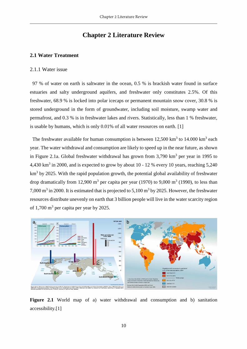
The freshwater available for human consumption is between 12,500 km3 to 14.000 km3 each
year. The water withdrawal and consumption are likely to speed up in the near future, as shown
in Figure 2.1a. Global freshwater withdrawal has grown from 3,790 km3 per year in 1995 to
4,430 km3 in 2000, and is expected to grow by about 10 - 12 % every 10 years, reaching 5,240
km3 by 2025. With the rapid population growth, the potential global availability of freshwater
drop dramatically from 12,900 m3 per capita per year (1970) to 9,000 m3 (1990), to less than
7,000 m3 in 2000. It is estimated that is projected to 5,100 m3 by 2025. However, the freshwater
resources distribute unevenly on earth that 3 billion people will live in the water scarcity region
of 1,700 m3 per capita per year by 2025.
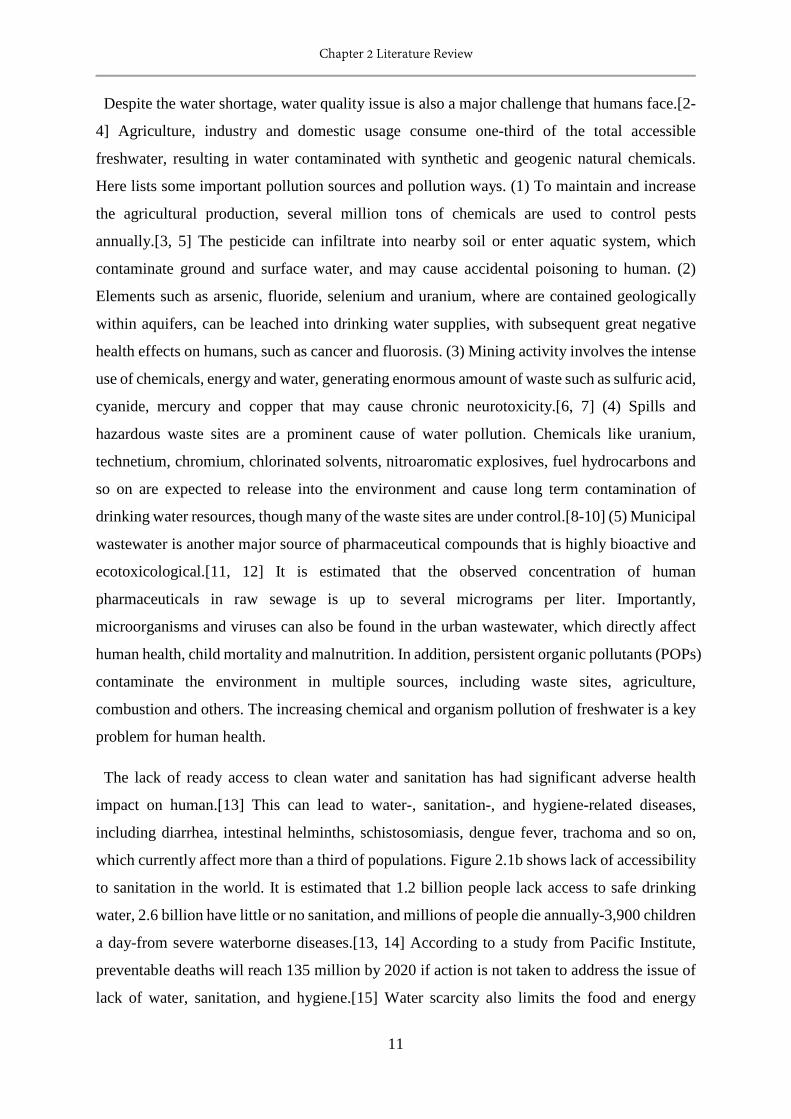
Figure 2.1 World map of a) water withdrawal and consumption and b) sanitation
accessibility.[1]
Chapter 2 Literature Review
11
Despite the water shortage, water quality issue is also a major challenge that humans face.[2-
4] Agriculture, industry and domestic usage consume one-third of the total accessible
freshwater, resulting in water contaminated with synthetic and geogenic natural chemicals.
Here lists some important pollution sources and pollution ways. (1) To maintain and increase
the agricultural production, several million tons of chemicals are used to control pests
annually.[3, 5] The pesticide can infiltrate into nearby soil or enter aquatic system, which
contaminate ground and surface water, and may cause accidental poisoning to human. (2)
Elements such as arsenic, fluoride, selenium and uranium, where are contained geologically
within aquifers, can be leached into drinking water supplies, with subsequent great negative
health effects on humans, such as cancer and fluorosis. (3) Mining activity involves the intense
use of chemicals, energy and water, generating enormous amount of waste such as sulfuric acid,
cyanide, mercury and copper that may cause chronic neurotoxicity.[6, 7] (4) Spills and
hazardous waste sites are a prominent cause of water pollution. Chemicals like uranium,
technetium, chromium, chlorinated solvents, nitroaromatic explosives, fuel hydrocarbons and
so on are expected to release into the environment and cause long term contamination of
drinking water resources, though many of the waste sites are under control.[8-10] (5) Municipal
wastewater is another major source of pharmaceutical compounds that is highly bioactive and
ecotoxicological.[11, 12] It is estimated that the observed concentration of human
pharmaceuticals in raw sewage is up to several micrograms per liter. Importantly,
microorganisms and viruses can also be found in the urban wastewater, which directly affect
human health, child mortality and malnutrition. In addition, persistent organic pollutants (POPs)
contaminate the environment in multiple sources, including waste sites, agriculture,
combustion and others. The increasing chemical and organism pollution of freshwater is a key
problem for human health.
The lack of ready access to clean water and sanitation has had significant adverse health
impact on human.[13] This can lead to water-, sanitation-, and hygiene-related diseases,
including diarrhea, intestinal helminths, schistosomiasis, dengue fever, trachoma and so on,
which currently affect more than a third of populations. Figure 2.1b shows lack of accessibility
to sanitation in the world. It is estimated that 1.2 billion people lack access to safe drinking
water, 2.6 billion have little or no sanitation, and millions of people die annually-3,900 children
a day-from severe waterborne diseases.[13, 14] According to a study from Pacific Institute,
preventable deaths will reach 135 million by 2020 if action is not taken to address the issue of
lack of water, sanitation, and hygiene.[15] Water scarcity also limits the food and energy
Chapter 2 Literature Review
12
production, industrial output, and the quality of our environment, affecting the economy.
International organizations have been setup to attract global attention and deal with the
accessibility of improved sanitation around the world. Reliable detection, wastewater
collection and treatment systems are all vital for safe water and human health.
2.1.2 Conventional water treatment system
Water treatment processes treat surface / ground water, industrial water and wastewater and
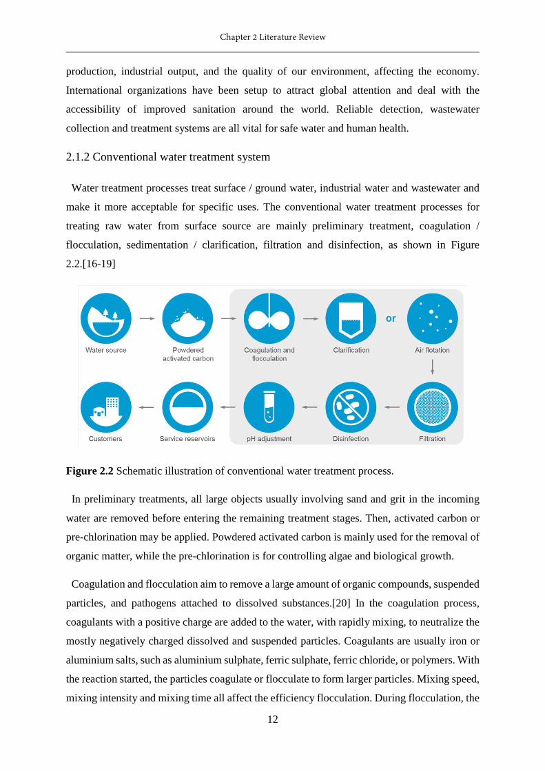
make it more acceptable for specific uses. The conventional water treatment processes for
treating raw water from surface source are mainly preliminary treatment, coagulation /
flocculation, sedimentation / clarification, filtration and disinfection, as shown in Figure
2.2.[16-19]
Figure 2.2 Schematic illustration of conventional water treatment process.
In preliminary treatments, all large objects usually involving sand and grit in the incoming
water are removed before entering the remaining treatment stages. Then, activated carbon or
pre-chlorination may be applied. Powdered activated carbon is mainly used for the removal of
organic matter, while the pre-chlorination is for controlling algae and biological growth.
Coagulation and flocculation aim to remove a large amount of organic compounds, suspended
particles, and pathogens attached to dissolved substances.[20] In the coagulation process,
coagulants with a positive charge are added to the water, with rapidly mixing, to neutralize the
mostly negatively charged dissolved and suspended particles. Coagulants are usually iron or
aluminium salts, such as aluminium sulphate, ferric sulphate, ferric chloride, or polymers. With
the reaction started, the particles coagulate or flocculate to form larger particles. Mixing speed,
mixing intensity and mixing time all affect the efficiency flocculation. During flocculation, the
Chapter 2 Literature Review
13
destabilized particles are further aggregated. The visible floc in the suspension is slowly mixed
using turbulence until it is sufficiently large to settle with gravity.
Following flocculation, the flocs are removed during clarification / sedimentation unit where
the flow slow down. In the clarification process, most of the flocs are removed by gravitational
settling, whilst the suspended particles in water are removed during filtration process. Air
flotation may also be used so that the suspended matter such as oil or solids can float to the
surface for easy removal via a filtration process.
In the filtration process, the relatively floc – free water flows through the filter by gravity,
with the nature of the particles removed from the water depending on the type of filter. Slow
sand filtration removes bacteria, protozoa and viruses, which produces essentially clean water.
In contrast, rapid sand filtration removes suspended particles, but does not remove bacteria,
protozoa or viruses. However, rapid sand filtration is much more commonly used, because the
water flow of rapid sand filtration is hundred times higher than the slow sand filtration process,
and it require relatively little space to operate. The most popular filter of the conventional
treatment process is composed of anthracite coal and sand.
Disinfection aims to kill remaining microorganisms in water, such as bacteria, viruses and
other pathogens. Normally, chlorine is used as the dosing chemical added to water.[21, 22]
Supplemental chlorine is added to continue disinfection of water while it moves through the
distribution network. However, the usage of chlorine to disinfect can lead to several problems.
Chlorination of organic materials can generate carcinogenic or harmful chlorinated-organic
compounds. Also, the residual chlorine may be able to chlorinate organic material in natural
aquatic environment. Ozonation is a popular and safer alternative to chlorination.
After all the above procedures, pH adjustment and fluoridation may be applied to treat the
water before storage and distributing to customer.
When treating wastewater, such as sewage, industrial and agricultural wastewater, additional
treatment is needed in addition to the above processes. A wastewater treatment plant may
include one or more of the following plants: oil-water separator, clarifier, roughing filter,
activated sludge, carbon filtration and advanced electrodialysis reversal system.
Centralized municipal wastewater systems can address many of the problems on water
contamination and sanitation, but they are often chemically, energetically and operationally
intensive. Developing a conventional water and wastewater treatment facility requires
Chapter 2 Literature Review
14
considerable capital and time, which precludes their use in much of the world, especially where
water is really needed. It is estimated that global annual infrastructure costs of US$100 billion
over the next 20 years.[3] In addition, the chemicals used in the treatment will become the
contaminating sources of freshwater. More effective, lower-cost, robust methods to purify
water are urgently needed, without further stressing the environment or endangering human
health by the treatment itself, as well as a cheap, fast and reliable detection method for detecting
pollutants in natural water.
2.1.3 Advanced water treatment technologies
To deal with the rapidly increasing water pollution, new types of pollutants and inaccessibility
of sanitation, advanced water treatment technologies have emerged to achieve a more robust,
cost-effective and greener water treatment system.[14, 23] In general, four processes have been
developed, advanced oxidation process, biological treatment, adsorption or ion exchange
process and membrane filtration. In this chapter, more attention is paid to the adsorption / ion
exchange process and the membrane filtration process as they are closely related to the works
done in the subsequent chapters.
2.1.3.1 Advanced oxidation process
Advanced oxidation processes (AOPs) have been developed to deal with the chemically
polluted water and wastewater, and show great potential for the treatment of ground water,
municipal wastewater sludge and volatile organic compounds (VOCs).[23, 24] AOPs are also
capable of treating problematic pollutants in water that may not be able to be removed
effectively by conventional treatment methods, such as persistent organic pollutants, which are
toxic, stable and active in the environment. The AOPs aim is to mineralize the organic pollutant
into relatively harmless inorganic molecules, such as carbon dioxide, water, sulphates and
nitrate.[25] To date, many AOPs have been developed for water and wastewater treatment,
including ultraviolet (UV) photolysis, solar photocatalysis, H2O2, Fenton’s reagent,
photocatalysis, ozone, sonolysis, radiation, supercritical water oxidation and so on.
Although there are more than 10 techniques classified as AOPs, these processes produce in
situ reactive free radicals, mainly hydroxyl radicals. The degradation of organic pollutants in
aqueous solution by AOPs is mainly achieved by a series of hydroxyl radicals initiated
reactions. Hydroxyl radicals (HO•) are a powerful oxidant that can be easily produced. As
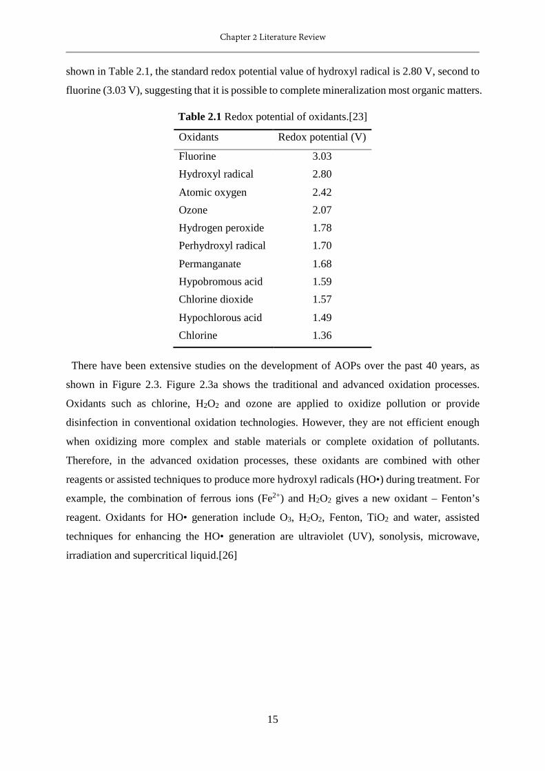
Chapter 2 Literature Review
15
shown in Table 2.1, the standard redox potential value of hydroxyl radical is 2.80 V, second to
fluorine (3.03 V), suggesting that it is possible to complete mineralization most organic matters.
Table 2.1 Redox potential of oxidants.[23]
Oxidants Redox potential (V)
Fluorine 3.03 Hydroxyl radical 2.80
Atomic oxygen 2.42 Ozone 2.07 Hydrogen peroxide 1.78 Perhydroxyl radical 1.70
Permanganate 1.68 Hypobromous acid 1.59 Chlorine dioxide 1.57
Hypochlorous acid 1.49 Chlorine 1.36
There have been extensive studies on the development of AOPs over the past 40 years, as
shown in Figure 2.3. Figure 2.3a shows the traditional and advanced oxidation processes.
Oxidants such as chlorine, H2O2 and ozone are applied to oxidize pollution or provide
disinfection in conventional oxidation technologies. However, they are not efficient enough
when oxidizing more complex and stable materials or complete oxidation of pollutants.
Therefore, in the advanced oxidation processes, these oxidants are combined with other
reagents or assisted techniques to produce more hydroxyl radicals (HO•) during treatment. For
example, the combination of ferrous ions (Fe2+) and H2O2 gives a new oxidant – Fenton’s
reagent. Oxidants for HO• generation include O3, H2O2, Fenton, TiO2 and water, assisted
techniques for enhancing the HO• generation are ultraviolet (UV), sonolysis, microwave,
irradiation and supercritical liquid.[26]
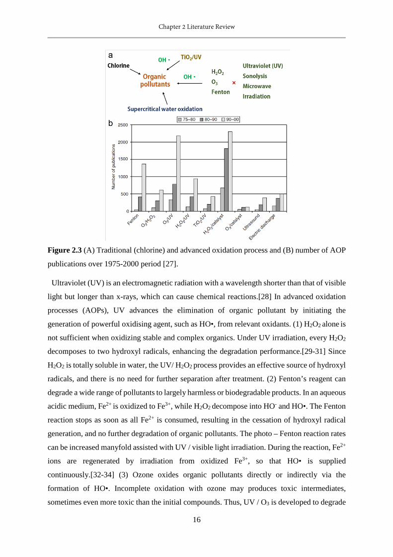
Chapter 2 Literature Review
16
Figure 2.3 (A) Traditional (chlorine) and advanced oxidation process and (B) number of AOP
publications over 1975-2000 period [27].
Ultraviolet (UV) is an electromagnetic radiation with a wavelength shorter than that of visible
light but longer than x-rays, which can cause chemical reactions.[28] In advanced oxidation
processes (AOPs), UV advances the elimination of organic pollutant by initiating the
generation of powerful oxidising agent, such as HO•, from relevant oxidants. (1) H2O2 alone is
not sufficient when oxidizing stable and complex organics. Under UV irradiation, every H2O2
decomposes to two hydroxyl radicals, enhancing the degradation performance.[29-31] Since
H2O2 is totally soluble in water, the UV/ H2O2 process provides an effective source of hydroxyl
radicals, and there is no need for further separation after treatment. (2) Fenton’s reagent can
degrade a wide range of pollutants to largely harmless or biodegradable products. In an aqueous
acidic medium, Fe2+ is oxidized to Fe3+, while H2O2 decompose into HO- and HO•. The Fenton
reaction stops as soon as all Fe2+ is consumed, resulting in the cessation of hydroxyl radical
generation, and no further degradation of organic pollutants. The photo – Fenton reaction rates
can be increased manyfold assisted with UV / visible light irradiation. During the reaction, Fe2+
ions are regenerated by irradiation from oxidized Fe3+, so that HO• is supplied
continuously.[32-34] (3) Ozone oxides organic pollutants directly or indirectly via the
formation of HO•. Incomplete oxidation with ozone may produces toxic intermediates,
sometimes even more toxic than the initial compounds. Thus, UV / O3 is developed to degrade

Chapter 2 Literature Review
17
organic pollutants more effectively through the generation of HO• from aqueous ozone
produced H2O2.[35, 36] UV / O3 / H2O2 is also used for treatment of organic compounds.
Photocatalysis is to accelerate a catalytic reaction involving light absorption by a catalyst.[37]
Photocatalysis can degrade a wide range of refractory organics into biodegradable compounds,
or even mineralize them.[38] Mild operating conditions, complete mineralization of organic
pollutants and the low operating cost made this process feasible for water treatment. In the
photocatalytic reaction, the catalyst absorbs a proton to excite an electron (e-) from valence
band (VB) to conduction band (CB), at the same time creating holes (h+) in the valence
band.[39] Those holes act as oxidizing agents, which generate free radicals able to undergo
further reactions. When h+ comes into contact with water molecules, HO• and H+ are produced.
On the other hand, electrons can react with dissolved oxygen to generate O2-• ions, then the
peroxide radicals react with water molecules, H+ and h+ to eventually form HO•.
Semiconductors, such as TiO2, ZnO, Fe2O3, CdS, GaP and ZnS, have been shown to be suitable
photocatalysts because of the appropriate positioning of VB and CB bands for adsorption of
light. Among the semiconductor catalysts studied, titanium dioxide (TiO2) is the most popular
and exhibits best performance for photocatalytic water treatment. TiO2 shows good chemical
and thermal stability, and it remains stable after repeated catalytic cycles under a photon
energies of 300 – 390 nm.[40, 41] In addition, development of catalyst with broader
photoactivity range and feasible photocatalytic system are challenges that attract intensive
attention.
Sonolysis –, microwave – assisted oxidation processes and supercritical water oxidation
process are also swell studied.[42-46] Sonolysis of water produces H• and HO• by thermal
dissociation of water. Sound waves are also used to enhance the performance of Fenton process,
ozonation process and the activity of catalyst or photocatalyst. It is observed that microwave
can greatly enhance the efficiency of AOPs, but the performance is not as good as using
ultraviolet. By taking advantage of the unique properties of supercritical water, organic
pollutants is mineralized through adding oxygen into the water.
Advanced oxidation processes provide a promising technology for the treatment of
wastewater containing organic pollutants, and have demonstrated their ability to solve this
problems in a greener, cost-efficient, practical way.
Chapter 2 Literature Review
18
2.1.3.2 Biological treatment
Biological treatment has been used for consuming biodegradable soluble organic
contaminants and removal of nitrogen and phosphorus in the conventional wastewater
treatment system.[47] The practical value of biological water treatment technologies arises for
several reasons.[25] Firstly, this process is very practical, it can be carried out in situ at the
polluted site. Secondly, it is an environmentally friendly technology, without generating
secondary pollution. Thirdly, it is cost-effective. The recent development of this utilized
technology is concentrated on removal of metal ions and oils.
Mining activity mobilize more than 5×10¹⁰ metric tons of geological materials annually in
our world,[1] and can also cause significant environmental problems, constituting the most
common metal pollution in fresh water. Biological treatments have been proven successful for
efficient removal of metal ions from contaminated water.[48-50] Generally, metal ions can be
treated by biosorption, bioaccumulation and phytoremediation.
Biosorption is the uptake of toxicants by dead/inactive biomaterials or by materials derived
from biological sources. Depending on the biosorbent used in the process, the mechanism of
metal removal can be physical adsorption, ion exchange, complexation, chelation and micro-
precipitation.[51] Several bacterial, fungal biomass and seaweed show good biosorption
capacity of relevant metal ions. For example, the biosorption capacities of a bacterial biomass,
Corynebaterium glutamicum, for adsorbing lead and nickel are 568 and 111 mg/g, respectively.
[49, 52] A kind of seaweed, Ascophyllum nodosum, adsorbs 215 mg/g cadmium and 136 mg/g
nickel.[53, 54] In addition, as an industrial waste, crab shell performs very good, the relevant
adsorption capacity of cadmium, cobalt, copper, lead, nickel and zinc are 199, 510, 244, 870,
170 and 124 mg/g, respectively.[55-60] However, most research focus on the biosorption of
metal ion, but few reports desorption and regeneration of biomaterials, which indicates the
industrial applicability of the process.
Bioaccumulation is the uptake of metal ions by living cells. In this process, metal ions are
bound onto the cell by rapid sorption, then accumulated inside the cell by metabolism.[61]
Bioaccumulation is usually conducted in batch systems. Thus, additional processes, such as
harvesting, drying, processing and storing, are reduced.[62, 63] However, it is not feasible to
treat solutions with high pollutants loading. The uptake capacity of bioaccumulation is about
one tenth of the biosorption process.
Chapter 2 Literature Review
19
Phytoremediation uses living plants to clean up chemically contaminated soil, air and
water.[64] Four different processes mediated by plants are developed for treating metal
polluted soil, sediment and water, including rhizofiltration, phytostabilization,
phytovolatilization and phytoextraction. Rhizofiltraiton uses hydroponically cultivated plants
to absorb and concentrate metals in their roots and shoots in the metal contaminated water.[65]
Phytostabilization reduces the migration of pollutants in the soil. Phytovolatilization removes
pollutants from soil or water and release it to air by transforming them to a volatile form.
Phytoextraction concentrates the pollutants into the plant biomass from environment. The
phytoremediation process is cost-effective, easily monitored, but it is a long term remediation
method. Over the past 20 years, this technology has been employed to deal with organic and
inorganic contaminants all over the world.
The increasing amounts of oily wastewater from oil fields, oil mills, petroleum industry,
frequent oil spill accident, and domestic households poses a major threat to the environment.
The oil water mixtures can be separated by gravity separation and filtration. The oil water
emulsions can be treated by centrifugation or ultrafiltration. However, dissolved oil in water is
difficult to remove, and causes serious issues of toxicity. Biological treatment has been proven
to treat it effectively by degrading the hydrocarbon to CO2, H2O and biomass. Oil
bioremediation can be achieved by direct addition of microorganisms into the pollution sites,
and / or addition of nitrogen and phosphorous to initiate the growth of microorganisms.[66, 67]
Microorganisms have been studied to treat drilling fluid contaminated waste water, edible oil
contaminated wastewater and petroleum contaminated wastewater. To treat the drilling fluid,
suitable carbon source is added after the dilution of wastewater with water, followed by
inoculating of metal treating and oil utilizing microorganisms. The resultant water can be
reused after separation the slurry or further treatment. This method removes metal and oil
contaminants at the same time. To treat petroleum contaminated wastewater, oleophilic oil-
eating microbes are used to break complex petroleum into fatty acids or carboxylic acids.[68]
If proper nutrients are introduced, these microorganisms can remove the oil completely.
There is no doubt that biological treatment is a promising alternative of conventional
wastewater treatment methods. With proper handling, microorganisms can not only survive in
tough environment, but also remove problematic organic and inorganic waste from water. More
pilot scale experiments are needed to be carried out to make biological treatment more reliable
for treating real wastewater.
Chapter 2 Literature Review
20
2.1.3.3 Adsorption or ion-exchange process
Adsorption and ion exchange processes are two of the most important water treatment
technologies that have been employed in many environmental applications, such as removal of
organic contaminants, taste and odor regulation, removal of sulfur compounds, toxic / heavy
metal removal, nitrogen and phosphorus removal, treatment of nuclear waste solutions,
produce high quality water, and so on.[69, 70] Adsorption is the adhesion of atoms, ions or
molecules onto the external and/or internal surface of a porous solid. Ion exchange is also a
sorption process using a porous solid, but only for ions, and for the sorption of every ion, there
is another ion(s) with equivalent charge released to the solution from the ion exchanger.
Adsorption
Adsorption is a process of enrichment of material on an interface.[71] It is of great
environmental, technological and biological importance, as it has been widely used in
separation, purification, catalysis, food processing, and pharmaceutical industries. Adsorption
is a consequence of surface energy.[72, 73] For solids, matter on the surface have more energy
than that inside the bulk, this excess energy is called “surface energy”. These surfaces are
available to rearrange or react to reduce their surface energy according to the Second Law of
Thermodynamics. Thus, it is more favourable to use adsorbents with high specific surface areas,
for example, industry uses adsorbents of fine particle size and a specific surface area larger
than 100 m2/g. To date, porous solid materials such as activated carbons, metal oxides, zeolites,
clays, and metal organic framework have been used as adsorbents for various applications, as
shown in Table 2.2.[74]
Activated carbon. The surface area of activated carbon normally ranges from 300 to 1500 m2/g,
with a pore volume between 0.7-1.8 cm3/g. The manufacture of activated carbon uses
carbonaceous material as a source, including wood, peat, coal, nutshells and so on. The
preparing process involves carbonization and activation.[75, 76] During the carbonization
process, the source material is heated up to 400-600 °C in an oxygen deficient atmosphere to
convert it into carbon or a carbon-containing residue. Activation aims to improve the
accessibility of pore structure by chemical activation or thermal activation. It also helps to open
and widen the micropores.
Activated carbon has been extensively used for the water treatment.[77] Organic compounds
like aromatic solvents, chlorinated aromatics, chlorophenols, polynuclear aromatics, pesticides
and herbicides, chlorinated nonaromatics, high molecular weight hydrocarbons and surfactants,
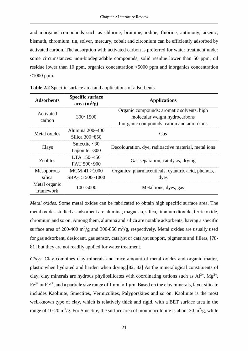
Chapter 2 Literature Review
21
and inorganic compounds such as chlorine, bromine, iodine, fluorine, antimony, arsenic,
bismuth, chromium, tin, solver, mercury, cobalt and zirconium can be efficiently adsorbed by
activated carbon. The adsorption with activated carbon is preferred for water treatment under
some circumstances: non-biodegradable compounds, solid residue lower than 50 ppm, oil
residue lower than 10 ppm, organics concentration <5000 ppm and inorganics concentration
<1000 ppm.
Table 2.2 Specific surface area and applications of adsorbents.
Adsorbents Specific surface area (m2/g) Applications
Activated carbon
300~1500 Organic compounds: aromatic solvents, high
molecular weight hydrocarbons Inorganic compounds: cation and anion ions
Metal oxides Alumina 200~400
Silica 300~850 Gas
Clays Smectite ~30
Laponite ~300 Decolouration, dye, radioactive material, metal ions
Zeolites LTA 150~450 FAU 500~900
Gas separation, catalysis, drying
Mesoporous silica
MCM-41 >1000 SBA-15 500~1000
Organics: pharmaceuticals, cyanuric acid, phenols, dyes
Metal organic framework
100~5000 Metal ions, dyes, gas
Metal oxides. Some metal oxides can be fabricated to obtain high specific surface area. The
metal oxides studied as adsorbent are alumina, magnesia, silica, titanium dioxide, ferric oxide,
chromium and so on. Among them, alumina and silica are notable adsorbents, having a specific
surface area of 200-400 m2/g and 300-850 m2/g, respectively. Metal oxides are usually used
for gas adsorbent, desiccant, gas sensor, catalyst or catalyst support, pigments and fillers, [78-
81] but they are not readily applied for water treatment.
Clays. Clay combines clay minerals and trace amount of metal oxides and organic matter,
plastic when hydrated and harden when drying.[82, 83] As the mineralogical constituents of
clay, clay minerals are hydrous phyllosilicates with coordinating cations such as Al3+, Mg2+,
Fe3+ or Fe2+, and a particle size range of 1 nm to 1 μm. Based on the clay minerals, layer silicate
includes Kaolinite, Smectites, Vermiculites, Palygorskites and so on. Kaolinite is the most
well-known type of clay, which is relatively thick and rigid, with a BET surface area in the
range of 10-20 m2/g. For Smectite, the surface area of montmorillonite is about 30 m2/g, while

Chapter 2 Literature Review
22
that of laponite can be up to 300 m2/g.[84] Due to their inertness, stability and low cost, clays
have been used in many industrial applications that are directly related to the adsorbent
properties. In the water treatment process, clays can be used for decolouration, dye adsorption,
radioactive materials adsorption and heavy metal adsorption.[85-87]
Zeolites. Zeolites are microporous, aluminosilicate minerals, have a general formula of
Mx/n[(AlO2)x(SiO2)y]·mH2O. [(AlO2)x(SiO2)y] constitutes the zeolite framework, while M is the
exchangeable cation, such as Na+, K+, Ca2+ and Mg2+. The zeolites can be divided to zeolite A,
zeolite X, zeolite Y and Pentasil zeolites with more specific formula. Zeolites can be obtained
naturally or synthesized from alumina, silica and base. The synthesis of zeolite involves the
formation of poorly ordered aluminosilicate hydrogel, the growth of oligomer precursors and
the development of crystallinity.[88] The synthetic zeolites are uniform and phase pure. The
effective pore volume for N2 of Ca6A (zeolite A) is about 0.30 cm3/g, those of NaX (Si/Al=1.25,
zeolite X) and Silicalite I (Pentasil zeolites) are 0.35 and 0.19 cm3/g, respectively. The zeolites
are of great fundamental and technological importance, have been applied for catalysis, gas
separation and drying. In liquid adsorption application, zeolite can adsorb Ca2+ and Mg2+ in
replace of Na+ to soften water.
Mesoporous silica. Mesoporous silica such as MCM-41 and SBA-15 comprises uniform
ordered pores / channels, high pore volume and high surface area, which is a promising
adsorbent for water treatment and catalysis.[89, 90] The pore/ channel size can be tuned by
using surfactants of different length or by varying synthesis conditions. Functionalized
mesoporous silica has also been made to extend the applications of this adsorbent. Mesoporous
silica has been investigated for the removal of organics in aqueous solution, including
pharmaceuticals, cyanuric acid, phenols and dyes.
Metal organic framework. Metal organic frameworks (MOFs) are an emerging class of porous
materials built from organic linkers and inorganic metal nodes or metal-based clusters through
coordination bonds, and are well known for high surface area, uniform pore size, controllable
structures, and readily tailorable functions.[91-93] Highly porous and flexible MOFs have
shown great potential as high-performance adsorbents in the development of advanced
adsorption technology. Compared to the other adsorbents, MOFs show several advantages:[94-
96] 1) it has relatively high surface area, which can be up to 5000 m2/g, so that it is possible to
adsorb large amount of molecules per volume unit. 2) It has flexible and designable chemical

Chapter 2 Literature Review
23
structure that can be functionalized by organic or inorganic compounds. 3) The high surface
area may also advance the MOF adsorption process faster.
The current research on MOFs focus has been mainly involved gas storage, gas separation
and purification, catalysis, drug delivery and sensor.[97] However, MOF-based materials have
recently been explored for adsorbing organic compounds, cations and anions in liquid phase.
In general, the uniform framework structure and high surface area endow the MOF-based ion
adsorbents with superior ion adsorption kinetics and remarkable uptake capacity. To date, the
research has been mainly focused on the adsorption properties of pristine MOFs. On the other
hand, the MOF-based ion adsorbents have been mainly used to adsorb metal pollutants in oxo-
hydroxo anion forms such as perchlorate, chromate, selenite and arsenate in water treatment
and purification processes. In addition, the regeneration of spent MOFs usually requires the
use of chemicals via ion exchange process.
Ion-exchange process
Ion exchange processes are one of the most important scientific developments of the 20th
century, and have been applied for water softening, environmental remediation, wastewater
treatment, hydrometallurgy, chromatography, biomolecular separation and catalysis.[70] As
the key component of ion exchange process, ion exchangers are insoluble solid materials
carrying exchangeable cations or ions.[98] The ion exchanger can be natural or artificial
materials, inorganic or polymeric materials. With the development of ion exchange technology,
the artificial polymeric resin has become the most popular and practical ion exchangers, and
widely applied. The synthetic resin is well known for high capacity, wide versatility, low cost,
and designable structure. Here, the species and applications of polymeric resin is introduced.
The polymeric resin is composed of a crosslinked network of hydrocarbon chains and
functional groups with ionic charges at various positions. A proper crosslinking density makes
the resin insoluble in water and ensure the swelling. Polystyrene divinylbenzene is commonly
used as the matrix (hydrocarbon chains) of resin. Others, phenol-formaldehyde matrix and
acrylic/methacrylic acid – divinylbenzene matrix are also used. The polymeric resin can be
classified into four types according to the functional groups: strong acid cation resins, strong
base anion resins, weak acid cation resins and weak base anion resins.[77]
Strong acid cation resins. These resins are functionalized with sulfonic acid groups (-SO3H)
or sodium sulfonate groups (-SO3Na), which can fully dissociate in water to form highly
ionized ion exchange sites. Na+ and H+ are highly exchangeable over the whole pH range.
Chapter 2 Literature Review
24
Strong acid cation resin can exchange with all kinds of cations in water, including monovalent
and multivalent ions. The sodium form is preferred for water softening, while the hydrogen
form is for preparing ultrapure water. The regeneration of resins is achieved by washing it with
strong acid or sodium chlorine solution.
Weak acid cation resins. The functional group of these resins is carboxylic acid group (-COOH),
which can partially dissociate in water to behave like weak organic acid. Thus, weak acid cation
resins can only exchange with multivalent cations, such as Mg2+ and Ca2+. Because of the good
affinity between –COOH and H+, these resins can be regenerated easier with lower amount of
acids.
As a kind of weak acid cation resin, heavy metal selective chelating resin can form complexes
with heavy metal ions, so that they are much more selective in heavy metal. Functional groups
with two or more chelating sites are usually used to decorate the resin, such as iminodiacetic
acid group, iminodiacetate, aminophosphonate, 8-hydroxyquinoline and picolylamine. The
relative selectivity of a commercial chelating resin for mercury is 2800 times as that of calcium.
Strong base anion resins. These resins are decorated with quaternary ammonium groups, and
are used in hydroxide form. The hydroxyl groups are fully dissociated in water, and can
exchange with all anions in water under an entire pH range. The regeneration of strong base
anion resins are treated with concentrated sodium hydroxide solutions.
Weak base anion resins. These kind of resins are functionalized with weak base such as primary,
secondary and tertiary amine. They can only exchange with strong acid in water, and the
exchange capacity is greatly affected by pH. Weak base anion resins are more readily
regenerated with lower concentration base solution compared to that of strong base anion resins.
2.1.3.4 Membrane separation technology
Membranes are a selective barrier that allow the permeation of some matter but block
others.[99, 100] There are both biological and synthetic membranes. Biological membranes
include cell membranes, nuclear membranes and tissue membranes. Synthetic membranes are
man-made and used in laboratories and industry. With regards membrane technology for water
treatment, only synthetic membranes are discussed in this study.
Synthetic membranes can be subdivided into symmetric and asymmetric membranes. The
development of asymmetric membrane is the breakthrough for industrial applications.[101]
Thinner membrane generates higher permeation. Asymmetric membranes are composed of a
Chapter 2 Literature Review
25
dense and thin selective layer (high rejection and permeation) and a porous support layer (good
mechanical property). The modern membrane separation industry started in 1960s with the
development of interfacial polymerization and multilayer composite coating. The Loeb-
Sourirajan process made defect-free, high flux reverse osmosis membranes with 10 times
higher flux than any membrane at that time.[102, 103] During 1970s and 1980s, microfiltration,
ultrafiltration, reverse osmosis and electrodialysis processes were all established. In 1980s,
membrane processes were applied for industrial gas separation. More recently from mid-1990s,
microfiltration / ultrafiltration processes have been developed as reliable and economical
systems for the treatment of municipal water sources and for sewage treatment integrated in
membrane bioreactor. Nowadays, membrane technology is very promising for water treatment
which has been widely applied.
Fabrication
Either inorganic or organic materials can be used for preparing membranes. The
manufacturing technique aims to fabricate membranes with certain structure or morphology
for a specific separation. Among the techniques developed, some of them are more important
and have been commonly used, including sintering, track-etching, phase inversion, sol-gel
process, vapor deposition and solution coating.
Sintering. The sintering method is a two steps process involves compressing powders and
sintering at elevated temperatures.[104, 105] The material used in this process normally has
outstanding chemical, thermal and mechanical stability, such as powders of polymers, metals,
graphite and glass. The sintering temperature depends on the material used. During sintering,
the interfaces between powders “melt” to form a continuous and porous membrane. The pore
sizes of this membrane is about 0.1-10 μm, and depends on the particle size of powders, while
the porosity is 10 to 20 %. The sintering method can prepared microfiltration membranes.
Track-etching. Using this method, a porous membrane with an assembly of parallel cylindrical
pores of uniform dimension can be fabricated. The preparation method starts with a dense film,
followed by a high energy particle radiation vertically applied on the film, and etching with
acid or alkaline solution.[106-108] The radiation particles create tracks in the matrix, and then
the acid or alkaline etches along these tracks to form uniform cylindrical pores. The radiation
time determines the porosity, while the etching time determines the pore diameter. The surface
porosity of membranes obtained using this method is low, usually not higher than 10%. The
pore size ranges from 0.02 to 10 μm.
Chapter 2 Literature Review
26
Phase inversion. Phase inversion is the most commonly used and versatile technique for
fabricating filtration membranes. Phase inversion is a process to transform polymer from liquid
state to solid state, which includes a range of different techniques, such as solvent evaporation,
evaporation-controlled precipitation, thermal precipitation, precipitation in vapor phase and
immersion precipitation.[99] Solvent evaporation is to evaporate the solvent of the liquid
polymer solution cast on a suitable support, in an inert and dry atmosphere to obtain a dense
and homogeneous membrane. In the vapor phase precipitation process, the casted liquid
polymer film is precipitated in an atmosphere with saturated nonsolvent vapor. The membrane
forms due to the penetration of nonsolvent into the polymer film, resulting in the formation of
porous membrane.Most of the membranes prepared in lab or for commercialization are phase
inversion membranes obtained by immersion precipitation. In this process, a casted liquid
polymer solution film is immersed in a nonsolvent / coagulation bath.[109-111] The exchange
of solvent and nonsolvent precipitates the polymer to be a porous membrane.
Solvent/nonsolvent pair is an important factors affecting the membrane structure. Water is
often used as a nonsolvent. Polymer concentration, evaporation time, humidity, temperature
and casting solution composition are also parameters determining the membrane performance.
The obtained membrane can be used directly or for post treatment.
Coating. As mentioned above, thinner membrane generates higher water flux. To increase the
water flux, composites membranes with a porous support layer and a very thin selective layer
are desired. Thus, the support layer and selective layer can be optimized independently for
optimal performance, such as permeation, selectivity, stability and mechanical properties. The
support layers are often asymmetric membranes obtained from phase inversion. Coating
procedures such as dip coating,[112, 113] spray coating, spin coating,[114, 115] grafting,
plasma polymerization, interfacial polymerization and in situ polymerization[116, 117] can be
applied to prepare these membranes.
In the case of dip-coating, an asymmetric membrane is firstly immersed in a low concentration
coating solution containing polymer, monomer or crosslinker, and then coated membrane is
placed in oven to evaporate the solvent and crosslink it.[113] Membranes prepared by dip-
coating are used in reverse osmosis, gas separation and pervaporation. In the interfacial
polymerization process, the reaction occurs on the active surface of support layer between two
very active monomers dissolved in two immiscible solvents. Amine and acid chloride /
isocyanate are usually used as the active monomer pair. A polymer film thinner than 50 nm
can be obtained through this technique.
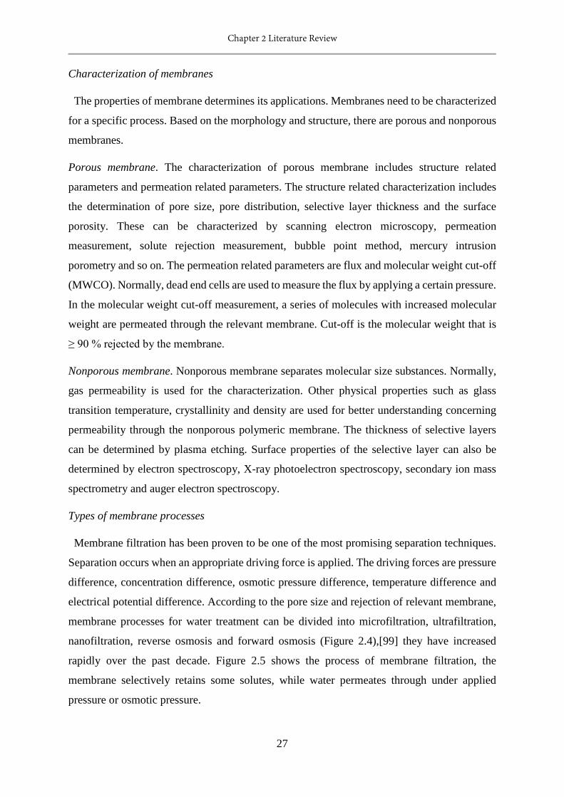
Chapter 2 Literature Review
27
Characterization of membranes
The properties of membrane determines its applications. Membranes need to be characterized
for a specific process. Based on the morphology and structure, there are porous and nonporous
membranes.
Porous membrane. The characterization of porous membrane includes structure related
parameters and permeation related parameters. The structure related characterization includes
the determination of pore size, pore distribution, selective layer thickness and the surface
porosity. These can be characterized by scanning electron microscopy, permeation
measurement, solute rejection measurement, bubble point method, mercury intrusion
porometry and so on. The permeation related parameters are flux and molecular weight cut-off
(MWCO). Normally, dead end cells are used to measure the flux by applying a certain pressure.
In the molecular weight cut-off measurement, a series of molecules with increased molecular
weight are permeated through the relevant membrane. Cut-off is the molecular weight that is
≥ 90 % rejected by the membrane.
Nonporous membrane. Nonporous membrane separates molecular size substances. Normally,
gas permeability is used for the characterization. Other physical properties such as glass
transition temperature, crystallinity and density are used for better understanding concerning
permeability through the nonporous polymeric membrane. The thickness of selective layers
can be determined by plasma etching. Surface properties of the selective layer can also be
determined by electron spectroscopy, X-ray photoelectron spectroscopy, secondary ion mass
spectrometry and auger electron spectroscopy.
Types of membrane processes
Membrane filtration has been proven to be one of the most promising separation techniques.
Separation occurs when an appropriate driving force is applied. The driving forces are pressure
difference, concentration difference, osmotic pressure difference, temperature difference and
electrical potential difference. According to the pore size and rejection of relevant membrane,
membrane processes for water treatment can be divided into microfiltration, ultrafiltration,
nanofiltration, reverse osmosis and forward osmosis (Figure 2.4),[99] they have increased
rapidly over the past decade. Figure 2.5 shows the process of membrane filtration, the
membrane selectively retains some solutes, while water permeates through under applied
pressure or osmotic pressure.
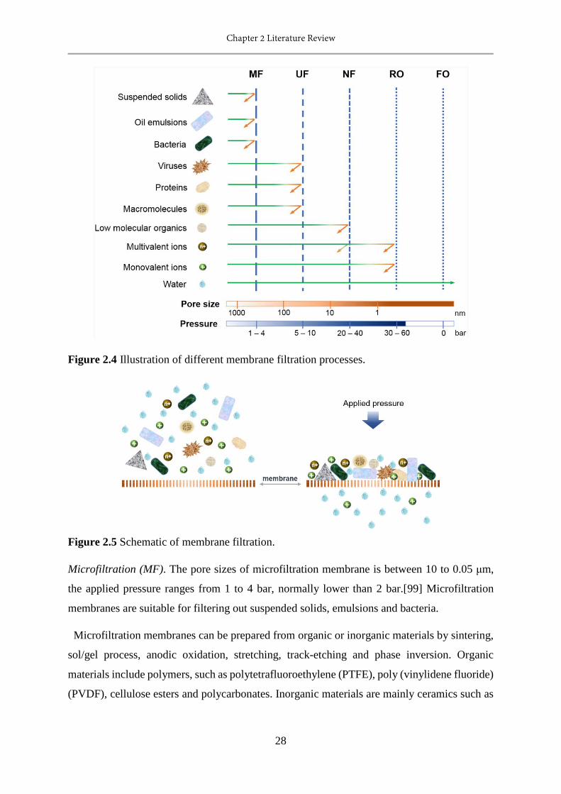
Chapter 2 Literature Review
28
Figure 2.4 Illustration of different membrane filtration processes.
Figure 2.5 Schematic of membrane filtration.
Microfiltration (MF). The pore sizes of microfiltration membrane is between 10 to 0.05 μm,
the applied pressure ranges from 1 to 4 bar, normally lower than 2 bar.[99] Microfiltration
membranes are suitable for filtering out suspended solids, emulsions and bacteria.
Microfiltration membranes can be prepared from organic or inorganic materials by sintering,
sol/gel process, anodic oxidation, stretching, track-etching and phase inversion. Organic
materials include polymers, such as polytetrafluoroethylene (PTFE), poly (vinylidene fluoride)
(PVDF), cellulose esters and polycarbonates. Inorganic materials are mainly ceramics such as
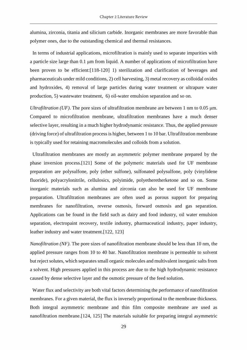
Chapter 2 Literature Review
29
alumina, zirconia, titania and silicium carbide. Inorganic membranes are more favorable than
polymer ones, due to the outstanding chemical and thermal resistances.
In terms of industrial applications, microfiltration is mainly used to separate impurities with
a particle size large than 0.1 μm from liquid. A number of applications of microfiltration have
been proven to be efficient:[118-120] 1) sterilization and clarification of beverages and
pharmaceuticals under mild conditions, 2) cell harvesting, 3) metal recovery as colloidal oxides
and hydroxides, 4) removal of large particles during water treatment or ultrapure water
production, 5) wastewater treatment, 6) oil-water emulsion separation and so on.
Ultrafiltration (UF). The pore sizes of ultrafiltration membrane are between 1 nm to 0.05 μm.
Compared to microfiltration membrane, ultrafiltration membranes have a much denser
selective layer, resulting in a much higher hydrodynamic resistance. Thus, the applied pressure
(driving force) of ultrafiltration process is higher, between 1 to 10 bar. Ultrafiltration membrane
is typically used for retaining macromolecules and colloids from a solution.
Ultrafiltration membranes are mostly an asymmetric polymer membrane prepared by the
phase inversion process.[121] Some of the polymeric materials used for UF membrane
preparation are polysulfone, poly (ether sulfone), sulfonated polysulfone, poly (vinylidene
fluoride), polyacrylonitrile, cellulosics, polyimide, polyetheretherketone and so on. Some
inorganic materials such as alumina and zirconia can also be used for UF membrane
preparation. Ultrafiltration membranes are often used as porous support for preparing
membranes for nanofiltration, reverse osmosis, forward osmosis and gas separation.
Applications can be found in the field such as dairy and food industry, oil water emulsion
separation, electropaint recovery, textile industry, pharmaceutical industry, paper industry,
leather industry and water treatment.[122, 123]
Nanofiltration (NF). The pore sizes of nanofiltration membrane should be less than 10 nm, the
applied pressure ranges from 10 to 40 bar. Nanofiltration membrane is permeable to solvent
but reject solutes, which separates small organic molecules and multivalent inorganic salts from
a solvent. High pressures applied in this process are due to the high hydrodynamic resistance
caused by dense selective layer and the osmotic pressure of the feed solution.
Water flux and selectivity are both vital factors determining the performance of nanofiltration
membranes. For a given material, the flux is inversely proportional to the membrane thickness.
Both integral asymmetric membrane and thin film composite membrane are used as
nanofiltration membrane.[124, 125] The materials suitable for preparing integral asymmetric
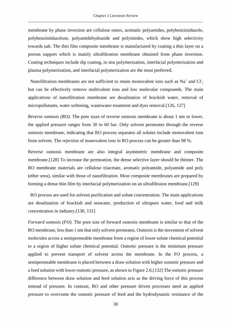
Chapter 2 Literature Review
30
membrane by phase inversion are cellulose esters, aromatic polyamides, polybenzimidazole,
polybenzimidazolone, polyamidehydrazide and polyimides, which show high selectivity
towards salt. The thin film composite membrane is manufactured by coating a thin layer on a
porous support which is mainly ultrafiltration membrane obtained from phase inversion.
Coating techniques include dip coating, in situ polymerization, interfacial polymerization and
plasma polymerization, and interfacial polymerization are the most preferred.
Nanofiltration membranes are not sufficient to retain monovalent ions such as Na+ and Cl-,
but can be effectively remove multivalent ions and low molecular compounds. The main
applications of nanofiltration membrane are desalination of brackish water, removal of
micropollutants, water softening, wastewater treatment and dyes removal.[126, 127]
Reverse osmosis (RO). The pore sizes of reverse osmosis membrane is about 1 nm or lower,
the applied pressure ranges from 30 to 60 bar. Only solvent permeates through the reverse
osmosis membrane, indicating that RO process separates all solutes include monovalent ions
from solvent. The rejection of monovalent ions in RO process can be greater than 98 %.
Reverse osmosis membrane are also integral asymmetric membrane and composite
membrane.[128] To increase the permeation, the dense selective layer should be thinner. The
RO membrane materials are cellulose triacetate, aromatic polyamide, polyamide and poly
(ether urea), similar with those of nanofiltration. Most composite membranes are prepared by
forming a dense thin film by interfacial polymerization on an ultrafiltraion membrane.[129]
RO process are used for solvent purification and solute concentration. The main applications
are desalination of brackish and seawater, production of ultrapure water, food and milk
concentration in industry.[130, 131]
Forward osmosis (FO). The pore size of forward osmosis membrane is similar to that of the
RO membrane, less than 1 nm that only solvent permeates. Osmosis is the movement of solvent
molecules across a semipermeable membrane from a region of lower solute chemical potential
to a region of higher solute chemical potential. Osmotic pressure is the minimum pressure
applied to prevent transport of solvent across the membrane. In the FO process, a
semipermeable membrane is placed between a draw solution with higher osmotic pressure and
a feed solution with lower osmotic pressure, as shown in Figure 2.6.[132] The osmotic pressure
difference between draw solution and feed solution acts as the driving force of this process
instead of pressure. In contrast, RO and other pressure driven processes need an applied
pressure to overcome the osmotic pressure of feed and the hydrodynamic resistance of the
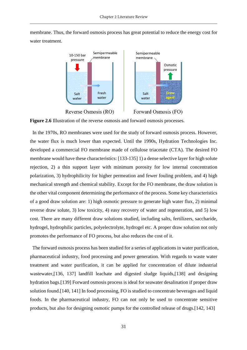
Chapter 2 Literature Review
31
membrane. Thus, the forward osmosis process has great potential to reduce the energy cost for
water treatment.
Figure 2.6 Illustration of the reverse osmosis and forward osmosis processes.
In the 1970s, RO membranes were used for the study of forward osmosis process. However,
the water flux is much lower than expected. Until the 1990s, Hydration Technologies Inc.
developed a commercial FO membrane made of cellulose triacetate (CTA). The desired FO
membrane would have these characteristics: [133-135] 1) a dense selective layer for high solute
rejection, 2) a thin support layer with minimum porosity for low internal concentration
polarization, 3) hydrophilicity for higher permeation and fewer fouling problem, and 4) high
mechanical strength and chemical stability. Except for the FO membrane, the draw solution is
the other vital component determining the performance of the process. Some key characteristics
of a good draw solution are: 1) high osmotic pressure to generate high water flux, 2) minimal
reverse draw solute, 3) low toxicity, 4) easy recovery of water and regeneration, and 5) low
cost. There are many different draw solutions studied, including salts, fertilizers, saccharide,
hydrogel, hydrophilic particles, polyelectrolyte, hydrogel etc. A proper draw solution not only
promotes the performance of FO process, but also reduces the cost of it.
The forward osmosis process has been studied for a series of applications in water purification,
pharmaceutical industry, food processing and power generation. With regards to waste water
treatment and water purification, it can be applied for concentration of dilute industrial
wastewater,[136, 137] landfill leachate and digested sludge liquids,[138] and designing
hydration bags.[139] Forward osmosis process is ideal for seawater desalination if proper draw
solution found.[140, 141] In food processing, FO is studied to concentrate beverages and liquid
foods. In the pharmaceutical industry, FO can not only be used to concentrate sensitive
products, but also for designing osmotic pumps for the controlled release of drugs.[142, 143]
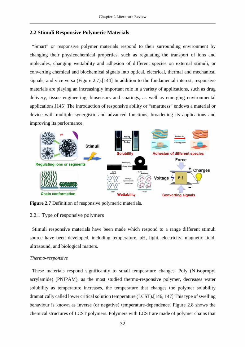
Chapter 2 Literature Review
32
2.2 Stimuli Responsive Polymeric Materials
“Smart” or responsive polymer materials respond to their surrounding environment by
changing their physicochemical properties, such as regulating the transport of ions and
molecules, changing wettability and adhesion of different species on external stimuli, or
converting chemical and biochemical signals into optical, electrical, thermal and mechanical
signals, and vice versa (Figure 2.7).[144] In addition to the fundamental interest, responsive
materials are playing an increasingly important role in a variety of applications, such as drug
delivery, tissue engineering, biosensors and coatings, as well as emerging environmental
applications.[145] The introduction of responsive ability or “smartness” endows a material or
device with multiple synergistic and advanced functions, broadening its applications and
improving its performance.
Figure 2.7 Definition of responsive polymeric materials.
2.2.1 Type of responsive polymers
Stimuli responsive materials have been made which respond to a range different stimuli
source have been developed, including temperature, pH, light, electricity, magnetic field,
ultrasound, and biological matters.
Thermo-responsive
These materials respond significantly to small temperature changes. Poly (N-isopropyl
acrylamide) (PNIPAM), as the most studied thermo-responsive polymer, decreases water
solubility as temperature increases, the temperature that changes the polymer solubility
dramatically called lower critical solution temperature (LCST).[146, 147] This type of swelling
behaviour is known as inverse (or negative) temperature-dependence. Figure 2.8 shows the
chemical structures of LCST polymers. Polymers with LCST are made of polymer chains that
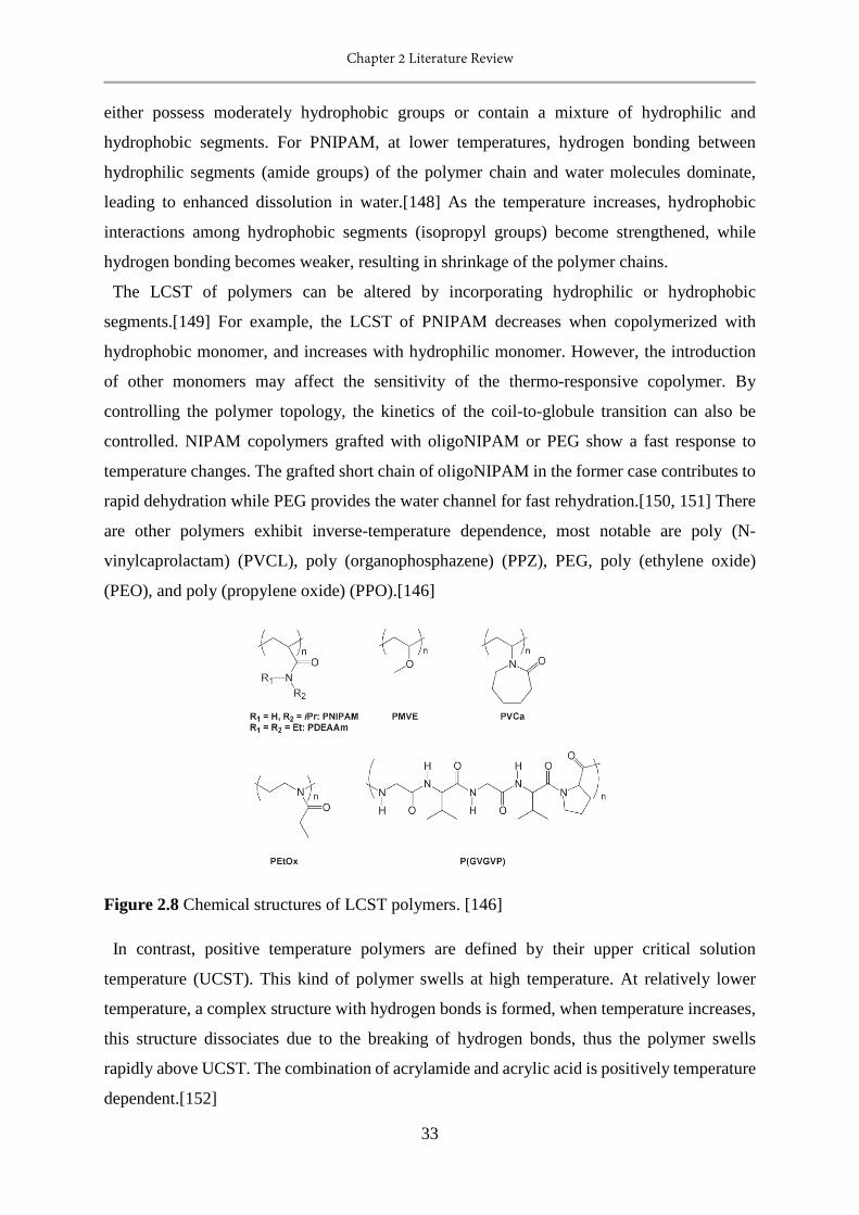
Chapter 2 Literature Review
33
either possess moderately hydrophobic groups or contain a mixture of hydrophilic and
hydrophobic segments. For PNIPAM, at lower temperatures, hydrogen bonding between
hydrophilic segments (amide groups) of the polymer chain and water molecules dominate,
leading to enhanced dissolution in water.[148] As the temperature increases, hydrophobic
interactions among hydrophobic segments (isopropyl groups) become strengthened, while
hydrogen bonding becomes weaker, resulting in shrinkage of the polymer chains.
The LCST of polymers can be altered by incorporating hydrophilic or hydrophobic
segments.[149] For example, the LCST of PNIPAM decreases when copolymerized with
hydrophobic monomer, and increases with hydrophilic monomer. However, the introduction
of other monomers may affect the sensitivity of the thermo-responsive copolymer. By
controlling the polymer topology, the kinetics of the coil-to-globule transition can also be
controlled. NIPAM copolymers grafted with oligoNIPAM or PEG show a fast response to
temperature changes. The grafted short chain of oligoNIPAM in the former case contributes to
rapid dehydration while PEG provides the water channel for fast rehydration.[150, 151] There
are other polymers exhibit inverse-temperature dependence, most notable are poly (N-
vinylcaprolactam) (PVCL), poly (organophosphazene) (PPZ), PEG, poly (ethylene oxide)
(PEO), and poly (propylene oxide) (PPO).[146]
Figure 2.8 Chemical structures of LCST polymers. [146]
In contrast, positive temperature polymers are defined by their upper critical solution
temperature (UCST). This kind of polymer swells at high temperature. At relatively lower
temperature, a complex structure with hydrogen bonds is formed, when temperature increases,
this structure dissociates due to the breaking of hydrogen bonds, thus the polymer swells
rapidly above UCST. The combination of acrylamide and acrylic acid is positively temperature
dependent.[152]
Chapter 2 Literature Review
34
pH-responsive
pH-responsive polymers undergo structural and property changes such as surface activity,
chain conformation, solubility and configuration in response to solution pH. The pH-sensitive
polymers contain pendant acidic or basic groups that either accept or release protons in
response to changes in environmental pH. In general, pH-responsive polymers made with basic
monomers act as cationic polymer in acidic condition, while those made with acidic monomers
act as anionic polymer in basic conditions.
The pH-responsive acidic polymers may have acidic group such as carboxylic groups,
sulfonic acid, phosphoric acid, boronic acid, or aminoacid.[153] Poly (acrylic acid) (PAA) and
poly (methacrylic acid) (PMAA) are the most widely reported pH-responsive polymers with
carboxylic groups. The most studied responsive polymers made with sulfonic acid are poly (2-
acrylamido-2-methylpropane sulfonic acid) (PAMPS) and poly (4-styrenesulfonic acid)
(PSSA).[154] The pH-responsive basic polymers contain tertiary amine groups, morpholino,
pyrrolidine, piperazine, pyridine, imidazole groups, or dendrimers. The most preferred basic
pH-responsive polymers are tertiary amine methacrylate based polymers, such as poly [(2-
dimethylamino) ethyl methacrylate] (PDMA), poly [(2-diethylamino) ethyl methacrylate]
(PDEA) and poly [(2-diisopropylamino) ethyl methacrylate] (PDPA).
The presence of ionizable groups on polymer chains results in swelling of the hydrogels much
beyond that can be achievable by non-electrolyte polymer hydrogels.[155] Since the swelling
of polyelectrolyte hydrogels is mainly due to the electrostatic repulsion among charges present
on the polymer chain, the extent of swelling is influenced by any condition that reduces the
electrostatic repulsion, such as pH, ionic strength, and type of counter ions.[156]
Photo-responsive
Light is an inexpensive and sustainable source of energy. It is straightforward and non-
invasive to use light to induce responsive behaviour. Photo-responsive polymers are
macromolecules that change their physiochemical properties in response to light irradiation of
appropriate wavelength and intensity.[157, 158] Their response leads to a light triggered self-
assembly, surface modification or patterning, swelling behaviour, shape change and
fluorescence emission of a material, opening a door for their use in reversible optical storage,
polymer viscosity control, photomechanical transduction/actuation, protein bioactivity
modulation, tissue engineering and drug delivery.[159] Typically, these changes are caused by
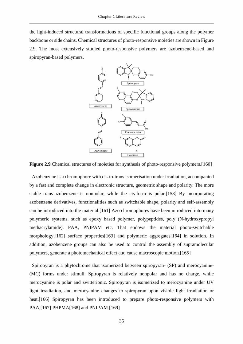
Chapter 2 Literature Review
35
the light-induced structural transformations of specific functional groups along the polymer
backbone or side chains. Chemical structures of photo-responsive moieties are shown in Figure
2.9. The most extensively studied photo-responsive polymers are azobenzene-based and
spiropyran-based polymers.
Figure 2.9 Chemical structures of moieties for synthesis of photo-responsive polymers.[160]
Azobenzene is a chromophore with cis-to-trans isomerisation under irradiation, accompanied
by a fast and complete change in electronic structure, geometric shape and polarity. The more
stable trans-azobenzene is nonpolar, while the cis-form is polar.[158] By incorporating
azobenzene derivatives, functionalities such as switchable shape, polarity and self-assembly
can be introduced into the material.[161] Azo chromophores have been introduced into many
polymeric systems, such as epoxy based polymer, polypeptides, poly (N-hydroxypropyl
methacrylamide), PAA, PNIPAM etc. That endows the material photo-switchable
morphology,[162] surface properties[163] and polymeric aggregates[164] in solution. In
addition, azobenzene groups can also be used to control the assembly of supramolecular
polymers, generate a photomechanical effect and cause macroscopic motion.[165]
Spiropyran is a phytochrome that isomerized between spiropyran- (SP) and merocyanine-
(MC) forms under stimuli. Spiropyran is relatively nonpolar and has no charge, while
merocyanine is polar and zwitterionic. Spiropyran is isomerized to merocyanine under UV
light irradiation, and merocyanine changes to spiropyran upon visible light irradiation or
heat.[166] Spiropyran has been introduced to prepare photo-responsive polymers with
PAA,[167] PHPMA[168] and PNIPAM.[169]

Chapter 2 Literature Review
36
Other than photo-responsive behaviour based on light-induced isomerisation, another
mechanism can also be stimulated by polarity changes from cleavage of photo-labile esters that
give birth corresponding alcohol and acid components, such as pyrenylmethyl chromophores
and pyrenylmethyl esters.
Electro-responsive
Electro-responsive polymers change their size and shape by swelling or shrinking in response
to an applied electric field. Transforming the electric signal into a physical response by a
polymer generally relies on the collapse of a gel, electrochemical reactions, electrically
activated complex formation, ionic polymer-metal interactions, electrorheological effects, or
changes in electrophoretic mobility.[170] These polymers can be ionic or dielectric. The
responsive mechanism of ionic polymer is that the mobility of free ions driven by electric field
changes the local ion concentrations in a solution or within a material, resulting in gel
deformation. The deformation of dielectric material is induced by electrostatic forces between
two electrodes.
Polyelectrolyte hydrogels are ionic electro-responsive polymers. Under electric fields, the
mobile, charged ions migrate toward cathode or anode, resulting in anisotropic swelling or
deswelling of the gel. Natural polymers such as chitosan, chondroitin sulfate, hyaluronic acid
and alginate, and synthetic polymers based on vinylalcohol, allylamine sulfonic acid, aniline,
2-hydroxyethyl methacrylate, methacrylic acid, acrylic acid and vinyl sulfonic acid have been
employed as an electro-responsive polymer.[171] In addition, an interpenetrating polymer
network hydrogel and copolymer hydrogel combing natural and synthetic component has also
been developed.[172] The bending rate and angle of the responsive polymer hydrogel is
characterized for different ionic strengths of the medium and magnitude of applied voltage to
determine the responsive ability. Ionic electro-responsive polymers require low actuation
voltages, but also exhibit low deformations and response rates, and they are usually performed
under wet conditions. Ionic polymer-metal composites show large bending strains under low
actuation voltages, which is very promising for actuators and sensors developments.
Dielectric polymers exhibit fast response and high deformations with high actuation fields,
and they are operated in dry conditions.[173] Poly (vinylidene fluoride)-based, polyacrylates
based-, and silicone-based non-ionic polymers with the presence of additional charge carrier
or polar component have been employed as electro-responsive materials.[174]
Chapter 2 Literature Review
37
Magneto-responsive
Magneto-responsive polymers can be prepared by introducing magnetic components within a
crosslinked network by physically entrapping or covalently immobilizing these units. The
distortion of shape and size occurs reversibly in the presence of non-uniform magnetic field.
Potential applications of these materials are using as soft biomimetic actuators, sensors, cancer
therapy agents, artificial muscles, switches, separation media, membranes and drug delivery
systems. The physical combination of magnetic (nano) particles and polymers has been well
documented, [175-177] such as PNIPAM and Fe3O4. These magnetic particles can be Fe3O4
and ferromagnetic cobalt nanoparticles. Over last decade, organometallic polymers have
attracted great attention by combining the valuable properties of metals and organic polymers,
opening new avenues in multi-responsive or multi-functional. Some examples of
organometallic polymers are oxanorbornene-based cobalt-containing diblock copolymer,
norbornene-based triblock copolymer comprising cobalt, pyrene and PEG-folate as pendant
groups and poly (4-(phenylethynyl)styrene)-b-PEO-b-poly(4-(phenylethynyl)styrene) (PPES-
b-PEO-b-PPES) triblock copolymers functionalized with Co2(CO)8.[178-180] The
development and exploration of all-organic magneto-responsive materials will pioneer a new
realm.
Ultrasound-responsive
Ultrasound is a high frequency sound waves that can be generated by mechanical oscillations
of a piezoelectric material, produced by applying an alternating current. Ultrasound has been
proven to be an effective stimuli that can be applied on demand and on site. The interaction
between ultrasound and a certain substance can induce thermal and cavitation effect. Thermal
effect is caused by the transfer of acoustic energy to the substance, resulting in temperature
rise. The cavitation effect generates gas bubbles in the substance as a result of the ultrasound
vibration. [181, 182] Transient bubble collapse generates local shock, which is considered the
main source for chemical and mechanical effects of ultrasonic energy.
Unlike polymers that can be triggered by other stimuli, ultrasound responsive polymers do
not have a specific or common characteristic. Generally, those materials which respond to
ultrasound are gels and other non-swollen macroscopic solids, polymeric micelles or layer-by-
layer coated microbubbles. The characterization of the ultrasound responsiveness of a polymer
is normally proceeded in an applications. The most studied application is ultrasound-induced
drug release. The drug release rate of copolymers from biodegradable polymeric materials,
Chapter 2 Literature Review
38
such as polyglycolides, polylactides, and poly [bis(p-carboxyphenoxy)alkane] anhydrides, and
sebacic acid and non-biodegradable ethylene-vinyl acetate, have been studied, and
demonstrated that the release kinetics enhanced significantly with increasing ultrasound
intensity.[183-185] This is due to the acceleration of the degradation of biodegradable
polymers by ultrasound. Ultrasound can also used to destabilize the supramolecular polymer
assemblies and coat stabilized microbubbles on a polymer.
Biologically responsive
The biologically responsive materials respond to biological small molecules or bio-
macromolecules. The responsiveness arises from the interaction between biological species
and the functional groups of responsive material, or the conjugation of synthetic polymer and
biological component.[171] Taking advantage of responding to natural systems, the
biologically responsive materials are promising for controlled drug delivery, bio-sensing /
diagnostics, smart films / matrices for tissue engineering, or in situ construction of structural
networks. The biological stimuli can be that they are glucose-, enzyme-, antigen- and redox /
thiol- responsiv.
Glucose-responsive polymers are of great importance in developing smart delivery systems
for insulin delivery which is triggered by a rise in blood glucose levels, aiming to treat diabetes
mellitus. The glucose-responsive materials are mainly based on the glucose oxidase (GOx)-
based reaction of glucose with oxygen. Glucose responsiveness is caused by the interaction of
the responsive polymer with the byproducts (gluconic acid and H2O2) from the enzymatic
oxidation of glucose. Thus, a pH responsive polymer is usually loaded or conjugated with GOx
to prepare a glucose-responsive polymer. pH-responsive polymers like poly(acrylic acid),[186]
poly (methacrylic acid),[187] and some polybase such as poly(2-hydeoxyethul methacrylate),
poly(N-isopropyl acrylamide) and their copolymer [188-190] have been integrated with GOx
to obtain glucose-responsive polymers. Poly (ethylene glycol) (PEG) and chitosan have also
been studied to increase the biocompatibility.[191, 192] The glucose responsiveness can also
be achieved by the binding of glucose with concanavalin A (ConA) [193] and the reversible
covalent bond of glucose and boronic acids.[194] In the glycopolymer-ConA complex, ConA
tends to crosslink or aggregate the glycopolymers, however, the binding of saccharide and
ConA can disrupt the aggregation, resulting in the release of insulin. Boronic acids can
reversibly complex with sugars, and are able to change their water solubility under different
pH or diol concentrations.
Chapter 2 Literature Review
39
Enzyme-responsive materials are usually applied for the in situ formation of hydrogels by an
enzyme triggered reaction, which shows potential in tissue engineering and drug delivery. They
can be fabricated by incorporating functional groups that react under enzymatic conditions.
[195] Proteases are widely employed as the enzyme in the reactions. Antigen-responsive
polymers swell and deswell upon the addition of antigen. This kind of materials are prepared
by incorporating antigen and antibody in a polymer, while the binding of antigen and antibody
crosslinks the polymers. When the antigen is added into the system, it binds with antibody of
the polymer, triggering swelling.[196] Redox / thiol-responsive polymers contain disulfide
linkages in the backbone or in the side chain. Disulphide bonds can be reversibly converted to
thiols upon various reducing agents, changing the solubility and swelling state of the polymer.
By taking advantage as the most abundant reducing agent in most cells, glutathione (GSH) has
been utilized to design redox / thiol-responsive drug delivery system to release therapeutics in
the cell.[197, 198]
2.2.2 Applications
The development of stimuli responsive materials is driven by a desire to mimic nature. To
date, this kind of material shows great potential and increasing importance in a diverse range
of applications (Figure 2.10), such as controlled drug delivery, diagnostics, tissue engineering,
sensors and biosensors, environmental remediation, chemo-mechanical actuators, as well as
microelectromechanical systems, textiles and coatings.[144, 145] Stimuli responsive materials
can not only applied itself as a functional material in a process, but can also be used to multi-
functionalize some other kinds of raw materials for advanced applications. The application of
stimuli responsive materials can be different due to different environmental stimuli.
Thermo-responsive polymers have been applied for the development of polymeric
temperature sensors, to control the proximity of side-chain functionalities, to control the
osmotic pressure of a polymer solution so that induce a reversible movement of water through
a semi-permeable membrane, for the collection of water from fogs and recovery, for passive
cooling building over water absorption and release upon different temperatures,[202] and for
the preparation of hydrogels for a specific use.[140]
Due to the pH variations along the gastrointestinal (GI) tract, pH-responsive polymers are
very promising for biology applications.[203] In the GI tract, the pH value of stomach is around
2, and pH 7 within colon, then up to pH 8.2 in duodenum. Thus, one of the most favourable
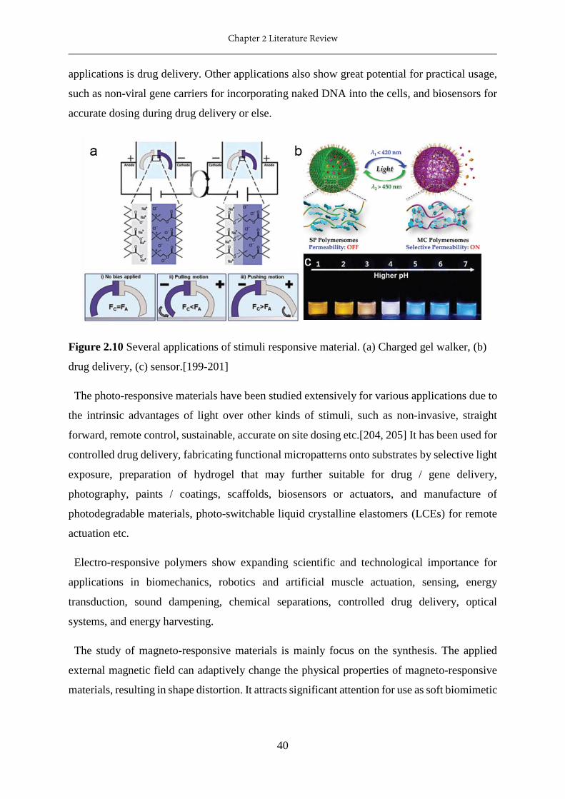
Chapter 2 Literature Review
40
applications is drug delivery. Other applications also show great potential for practical usage,
such as non-viral gene carriers for incorporating naked DNA into the cells, and biosensors for
accurate dosing during drug delivery or else.
Figure 2.10 Several applications of stimuli responsive material. (a) Charged gel walker, (b)
drug delivery, (c) sensor.[199-201]
The photo-responsive materials have been studied extensively for various applications due to
the intrinsic advantages of light over other kinds of stimuli, such as non-invasive, straight
forward, remote control, sustainable, accurate on site dosing etc.[204, 205] It has been used for
controlled drug delivery, fabricating functional micropatterns onto substrates by selective light
exposure, preparation of hydrogel that may further suitable for drug / gene delivery,
photography, paints / coatings, scaffolds, biosensors or actuators, and manufacture of
photodegradable materials, photo-switchable liquid crystalline elastomers (LCEs) for remote
actuation etc.
Electro-responsive polymers show expanding scientific and technological importance for
applications in biomechanics, robotics and artificial muscle actuation, sensing, energy
transduction, sound dampening, chemical separations, controlled drug delivery, optical
systems, and energy harvesting.
The study of magneto-responsive materials is mainly focus on the synthesis. The applied
external magnetic field can adaptively change the physical properties of magneto-responsive
materials, resulting in shape distortion. It attracts significant attention for use as soft biomimetic

Chapter 2 Literature Review
41
actuators, sensors, cancer therapy agents, artificial muscles, switches, separation media,
membranes and drug delivery.
The most favourable applications of biologically responsive materials are controlled drug
delivery, but are used in other applications like biosensing / diagnostics, cell support, injectable
scaffolds, and tissue engineering.
As a bridge connecting synthetic materials and devices and nature, most of the applications
of stimuli responsive materials are bio-related. The exploration of the fundamental science and
advanced applications of stimuli responsive material will lead to new, relevant processes in a
“smarter” new era.
2.3 Responsive Materials for Water Treatment
Recently, responsive materials have been introduced in the water treatment process,
responsive membrane, responsive forward osmosis draw agent and responsive adsorbent have
emerged, and gaining increasing concern in recent decades. The development of smart
membranes has been realized for the controllable separation process, and to produce anti-
fouling membrane and biomimetic membrane. Smart draw agents, which can recover water
with lower energy cost, lights the future of forward osmosis desalination process. The
responsive adsorbent that can be regenerated and recycled by stimuli, especially by physical
stimuli, is ideal for resource reclamation from contaminated water or water softening. Such
smart water treatment systems with self-cleaning, self-refreshing, energy-saving, or
controllable separation abilities will improve the efficiency of many technological processes,
and they have strong potential for future applications.
2.3.1 Responsive membrane
As the responsive material provides the membrane with responsiveness, it responds to
external stimuli, and thus the flux, solute selectivity and wettability become tunable via changes
in conformation of polymer chains. It is envisaged that combining various stimuli-induced
molecular level changes with versatility of membrane design would unlock the potential of
smart responsive membranes not only with better performance but also with unprecedented
functionalities for a wider range of applications. [206] For example, as has been learnt from
low-fouling surfaces in nature, the “self-cleaning” membrane could be fabricated with tunable
Chapter 2 Literature Review
42
or responsive properties, because the change in configuration between hydrophilic and
hydrophobic state can lead to desorption of absorbed solutes.
Stimuli-responsive membranes have a large number of previously established applications
and many more potential applications, where they are key components in complex technical
systems such as sensors, separation processes, and drug delivery devices. Increasing demand
has driven the development of responsive membranes. There are four essential elements of
smart membranes: [207] (1) responsivity of smart membranes changes in environmental
stimuli; (2) stability of the smart membrane processes; (3) reversibility of the response of smart
membranes to the environmental stimuli; (4) reproducibility of smart membrane materials and
processes.
Fabrication
According to the stimuli source, there are mainly seven types of responsive membranes,
including thermally responsive, pH-responsive, photo-responsive, electric field-responsive,
magnetic field-responsive, glucose-responsive and ionic strength-responsive membrane.
Responsive membranes responding to different stimuli often have similar fabrication methods.
[208] They can generally be fabricated by 1) processing the stimuli responsive materials
(polymers or copolymers) into membranes, or 2) modification of existing membranes by
physical / chemical methods to introduce stimuli responsive materials.
The membrane processing approach enables the stimuli responsive membranes with desired
mechanical properties, pore structure, barrier structure and layer thickness to be made. The
membrane processing methods for the preparation of membranes from stimuli responsive
materials include radiation induced in situ formation, solvent casting, interpenetrating networks
(IPNs) and phase inversion. In the radiation-based method, a mixture solution with monomers
and crosslinkers is coated on a porous film, followed by radiation to initiate the polymerization,
resulting in a film formed. In the solvent casting method, stimuli responsive polymers are
dissolved in solvent before casting on a flat glass plate, and allowing solvent evaporation. The
free-standing membranes obtained are dried and crosslinked. For preparation of
interpenetrating networks, a stimuli responsive monomer is polymerized within a crosslinked
network in the presence of crosslinker and initiator. The IPNs membrane shows good
mechanical strength due to the high levels of crosslinking. Phase inversion can also be applied
to prepare responsive membrane by immersing the casting solution of stimuli responsive
polymer in an appropriate non-solvent to enable the membrane formation.
Chapter 2 Literature Review
43
By surface modification, the useful properties of base membrane are preserved, and
responsive properties are introduced to the membrane. There are two modification approaches
employed for membrane functionalization, the “grafting to” and “grafting from”
technique.[209] Grafting is an important and widely used method to incorporate functional
moieties to the membrane. The “grafting to” technique incorporates terminal functionalized
small molecules or large marcomolecules onto the membrane surface. The “grafting to”
functionalization can be achieved by physical adsorption or chemical grafting. By physical
adsorption, a stimuli responsive polymer coating is formed on the membrane, which is done
by soaking a raw membrane in a polymer solution and allowing it to dry before annealing to
strengthen the attachment of coating to membrane. By chemical grafting, terminal
functionalized molecules / marcomolecules are activated by accelerator or catalyst to
immobilize the (marco) molecules on to the membrane surface. The “grafting from” technique
initiates the polymerization of stimuli responsive monomer and / or crosslinker on the
membrane surface, thus the polymer chains grow from initiator site on membrane surface. The
“grafting from” technique includes two steps: immobilization of initiator onto the membrane
surface, and activation of the initiator to trigger the polymerization of monomer. According to
different activation approach, this modification methods can be divided to photo-initiated (UV
and non-UV) grafting, redox-initiated grafting, plasma-initiated grafting, thermal grafting,
atom transfer radical polymerization (ATRP) and reversible addition-fragmentation chain
transfer (RAFT) polymerization.
Fundamental study
The current research of responsive membranes is mainly focussed on fundamental studies,
including the change of flux and solute selectivity, and the on-off state for different stimuli.
Stimuli responsive membranes can be classified as porous and non-porous membranes,
according to their morphology.
Porous membrane. Reber et al. prepared thermally responsive ion track membranes by
chemically grafting poly (N-isopropyl acrylamide) (PNIPAM) hydrogel onto the single/multi-
pore ion track membranes of poly (ethylene terephthalate) (PET).[210] It was found that the
incorporation of the hydrogel into the pores does not influence the phase transition temperature.
The bovin insulin permeation in the open state was 35 times above the level of the closed state.
In the open state, the transport rates of the solvent and the solute were identical implying that
the free space in the open pores was larger than the size of the permeating bovine albumin
Chapter 2 Literature Review
44
molecules (about 7.3 nm) and is not molecular selective. Choi et al. developed a temperature-
responsive membrane by grafting PNIPAM onto porous PP films for separations based on
solute hydrophobicity. [211] The water permeability of the membrane was temperature-
dependent, lower water flux at temperatures below LCST, and higher water fluxes at
temperature above LCST. Solutions containing hydrophobic and hydrophilic solutes were
supplied continuously to the feed side, while the membrane temperature was altered. It was
found that above LCST, only the hydrophobic solutes were adsorbed onto the membranes,
while the hydrophilic solutes permeated through the pores. By changing the temperature to
below LCST, the adsorbed hydrophobic solutes desorbed from the membranes. Thus, with
stepwise temperature change below and above LCST, specific solutes could be concentrated
and purified on the permeate side. Ito et al. designed nanopores, pH-responsive membranes by
self-assembly of ionizable polypeptide brushes on a gold-coated porous membrane.[212] At
low pH, poly (L-glutamic acid) (PLGA) chains are protonated and folded forming α-helical
structures that lie on the surface; at higher pH, they are deprotonated forming extended random
structures that extend into the solution. It was observed that the modified membranes were
dependent on pH, with high permeation at low pH and low permeation at near neutral pH.
Chung et al. grafted copolymerization of spiropyran-containing methacrylate (SPMMA) and
acrylamide (AM) on to the surface of a porous polytetrafluoroethylene (PTFE)
membranes.[213] It was found that the permeability of a water-methanol mixture through the
modified membranes was increased by UV irradiation, but decreased by visible light irradiation.
Chu et al. fabricated a temperature-responsive core-shell microcapsule with a porous outer
membrane and PNIPAM gates by using plasma-graft pore-filling polymerization.[214] As
shown in Figure 2.11, at low graft yields, the release rate was higher at temperatures above the
LCST than at temperatures below the LCST, due to pore opening controlled by the PNIPAM
gates. In contrast, at high graft yields, the release rate was lower at temperatures above the
LCST than at temperatures below the LCST, because the pores were fully blocked and a
PNIPAM layer covered the entire capsule surface.
Non-porous membrane. Yamakawa et al. Prepared temperature-responsive charged
membranes from the polymer mixture of poly (vinyl alcohol) (PVA), in situ polymer of N-
isopropyl acrylamide (NIPAM) and PVA, and a polyanion (poly (vinyl alcohol-co-2-
acrylamido-2-methylpropane sulfonic acid).[215] The permeation experiments in a dialysis
system consisting of the membrane and mixed KCl and CaCl2 solutions show that the transport
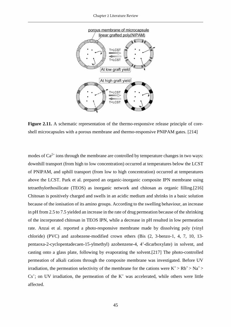
Chapter 2 Literature Review
45
Figure 2.11. A schematic representation of the thermo-responsive release principle of core-
shell microcapsules with a porous membrane and thermo-responsive PNIPAM gates. [214]
modes of Ca2+ ions through the membrane are controlled by temperature changes in two ways:
downhill transport (from high to low concentration) occurred at temperatures below the LCST
of PNIPAM, and uphill transport (from low to high concentration) occurred at temperatures
above the LCST. Park et al. prepared an organic-inorganic composite IPN membrane using
tetraethylorthosilicate (TEOS) as inorganic network and chitosan as organic filling.[216]
Chitosan is positively charged and swells in an acidic medium and shrinks in a basic solution
because of the ionisation of its amino groups. According to the swelling behaviour, an increase
in pH from 2.5 to 7.5 yielded an increase in the rate of drug permeation because of the shrinking
of the incorporated chitosan in TEOS IPN, while a decrease in pH resulted in low permeation
rate. Anzai et al. reported a photo-responsive membrane made by dissolving poly (vinyl
chloride) (PVC) and azobezene-modified crown ethers (Bis (2, 3-benzo-1, 4, 7, 10, 13-
pentaoxa-2-cyclopentadecaen-15-ylmethyl) azobenzene-4, 4’-dicarboxylate) in solvent, and
casting onto a glass plate, following by evaporating the solvent.[217] The photo-controlled
permeation of alkali cations through the composite membrane was investigated. Before UV
irradiation, the permeation selectivity of the membrane for the cations were K+ > Rb+ > Na+ >
Cs+; on UV irradiation, the permeation of the K+ was accelerated, while others were little
affected.

Chapter 2 Literature Review
46
Figure 2.12 The extended and contracted state of porous responsive membrane and their
permeation upon solutes.
To date, most of the studies on responsive membrane have focused on investigating the
change of permeation flux and pore size of the membrane under stimuli. Generally speaking,
as shown in Figure 2.12, for porous responsive membranes prepared by grafting method, there
are two distinct behaviours: at low graft yields, the permeation flux was higher in the contracted
state than the extended state due to pore opening; In contrast, at high graft yields, the
permeation flux was lower (or no flux) in the contracted state than the extended state, because
the pores were fully blocked and the responsive polymer covered the entire pore surface.
Researchers applied this responsive membrane in drug release because of this unique property.
Apart from the permeation flux and pore size, the change of hydrophilicity under stimuli has
also been studied. In the extended state, the membrane is hydrophilic; while in the contracted
state, it is hydrophobic. This property has been studied for concentrating and purifying the
hydrophilic and hydrophobic solutes. In addition, some of the responsive membranes also
possess ion-selectivity. These membranes may find use in self-regulating systems.
Applications
In the water treatment process, stimuli responsive membranes have been used for controllable
separation and addressing membrane fouling.
Controllable separation. Controllable oil water separation is the most studied controllable
separation process so far. Che et al. developed a CO2 responsive PMMA-co-PDEAEMA
polymer nanofibre membrane.[218] This smart nanostructured electrospun polymer membrane
is capable of switching oil / water wettability by bubbling and removing CO2. After CO2
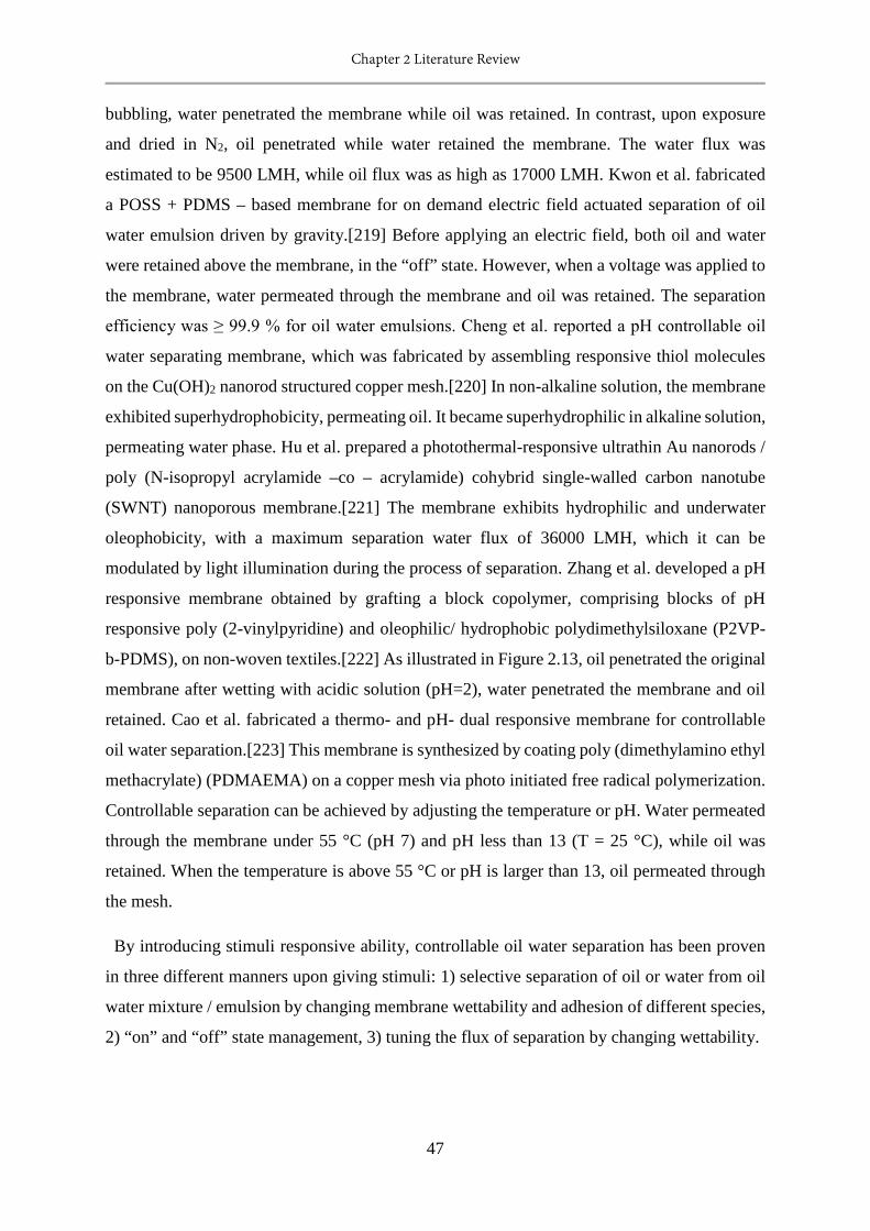
Chapter 2 Literature Review
47
bubbling, water penetrated the membrane while oil was retained. In contrast, upon exposure
and dried in N2, oil penetrated while water retained the membrane. The water flux was
estimated to be 9500 LMH, while oil flux was as high as 17000 LMH. Kwon et al. fabricated
a POSS + PDMS – based membrane for on demand electric field actuated separation of oil
water emulsion driven by gravity.[219] Before applying an electric field, both oil and water
were retained above the membrane, in the “off” state. However, when a voltage was applied to
the membrane, water permeated through the membrane and oil was retained. The separation
efficiency was ≥ 99.9 % for oil water emulsions. Cheng et al. reported a pH controllable oil
water separating membrane, which was fabricated by assembling responsive thiol molecules
on the Cu(OH)2 nanorod structured copper mesh.[220] In non-alkaline solution, the membrane
exhibited superhydrophobicity, permeating oil. It became superhydrophilic in alkaline solution,
permeating water phase. Hu et al. prepared a photothermal-responsive ultrathin Au nanorods /
poly (N-isopropyl acrylamide –co – acrylamide) cohybrid single-walled carbon nanotube
(SWNT) nanoporous membrane.[221] The membrane exhibits hydrophilic and underwater
oleophobicity, with a maximum separation water flux of 36000 LMH, which it can be
modulated by light illumination during the process of separation. Zhang et al. developed a pH
responsive membrane obtained by grafting a block copolymer, comprising blocks of pH
responsive poly (2-vinylpyridine) and oleophilic/ hydrophobic polydimethylsiloxane (P2VP-
b-PDMS), on non-woven textiles.[222] As illustrated in Figure 2.13, oil penetrated the original
membrane after wetting with acidic solution (pH=2), water penetrated the membrane and oil
retained. Cao et al. fabricated a thermo- and pH- dual responsive membrane for controllable
oil water separation.[223] This membrane is synthesized by coating poly (dimethylamino ethyl
methacrylate) (PDMAEMA) on a copper mesh via photo initiated free radical polymerization.
Controllable separation can be achieved by adjusting the temperature or pH. Water permeated
through the membrane under 55 °C (pH 7) and pH less than 13 (T = 25 °C), while oil was
retained. When the temperature is above 55 °C or pH is larger than 13, oil permeated through
the mesh.
By introducing stimuli responsive ability, controllable oil water separation has been proven
in three different manners upon giving stimuli: 1) selective separation of oil or water from oil
water mixture / emulsion by changing membrane wettability and adhesion of different species,
2) “on” and “off” state management, 3) tuning the flux of separation by changing wettability.
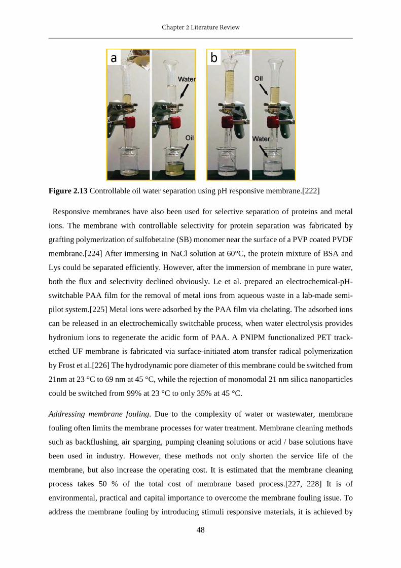
Chapter 2 Literature Review
48
Figure 2.13 Controllable oil water separation using pH responsive membrane.[222]
Responsive membranes have also been used for selective separation of proteins and metal
ions. The membrane with controllable selectivity for protein separation was fabricated by
grafting polymerization of sulfobetaine (SB) monomer near the surface of a PVP coated PVDF
membrane.[224] After immersing in NaCl solution at 60°C, the protein mixture of BSA and
Lys could be separated efficiently. However, after the immersion of membrane in pure water,
both the flux and selectivity declined obviously. Le et al. prepared an electrochemical-pH-
switchable PAA film for the removal of metal ions from aqueous waste in a lab-made semi-
pilot system.[225] Metal ions were adsorbed by the PAA film via chelating. The adsorbed ions
can be released in an electrochemically switchable process, when water electrolysis provides
hydronium ions to regenerate the acidic form of PAA. A PNIPM functionalized PET track-
etched UF membrane is fabricated via surface-initiated atom transfer radical polymerization
by Frost et al.[226] The hydrodynamic pore diameter of this membrane could be switched from
21nm at 23 °C to 69 nm at 45 °C, while the rejection of monomodal 21 nm silica nanoparticles
could be switched from 99% at 23 °C to only 35% at 45 °C.
Addressing membrane fouling. Due to the complexity of water or wastewater, membrane
fouling often limits the membrane processes for water treatment. Membrane cleaning methods
such as backflushing, air sparging, pumping cleaning solutions or acid / base solutions have
been used in industry. However, these methods not only shorten the service life of the
membrane, but also increase the operating cost. It is estimated that the membrane cleaning
process takes 50 % of the total cost of membrane based process.[227, 228] It is of
environmental, practical and capital importance to overcome the membrane fouling issue. To
address the membrane fouling by introducing stimuli responsive materials, it is achieved by
Chapter 2 Literature Review
49
improving the hydrophilicity of membrane or the oscillation between swollen and collapsed
conformations of the responsive polymer, resulting in desorption of adsorbed fouling.
Han et al. fabricated a pH responsive membrane by blending pH responsive copolymers, poly
(methyl methacrylate-co-acrylic acid) (PMMA-AA) or poly (methyl methacrylate-co-4-vinyl
pyridine) (PMMA-4VPy), with polyethersulfone (PES), and forming via phase inversion.[229]
The protein (BSA) ultrafiltraion experiments showed that the membrane exhibited excellent
anti-fouling property, which is due to the increased hydrophilicity of membrane and the same
negatively charge of BSA and PAA in neutral solution. Cheng et al. prepared a pH sensitive
hollow fibre membrane by blending PES with an amphiphilic copolymer poly (styrene- acrylic
acid-N-vinylpyrrolidone) (PSt-AA-NVP).[230] The anti-fouling performance and flux
recovery ratios increased after blending with PSt-AA-NVP that was because pH induced phase
separation of the copolymer, resulting in the surface aggregation of AA and NVP chains,
preventing the protein adsorption onto the membrane surface. Yu et al. modified a thin film
composite reverse osmosis membrane by depositing thermo-responsive polymer, poly (N-
isopropyl acrylamide-co-acrylamide) (PNIPAM-co-AM), on membrane surface. This
membrane exhibited significantly enhanced antifouling properties and cleaning efficiency.[231]
The enhanced antifouling performance was because of the improved wettability of membrane
surface. The improved cleaning efficiency of the modified membrane was due to the phase
transition of the thermo-responsive polymer coating layer. Meng et al. modified the TFC-RO
membrane by redox initiated grafting of a zwitterionic polymer poly (4-(2-sulfoethyl)-1-(4-
vinylbenzyl) pyridinium betaine) (PSVBP) to obtain a salt-responsive membrane.[232] The
incorporation of PSVBP improved the antifouling property by increasing the hydrophilicity
and negatively charged density on the membrane surface. On the other hand, the improved
cleaning efficiency was attributed to the state transition of the salt-responsive polymer,
facilitating the removal of foulants on membrane surface. Zhou et al. designed a thermo-
responsive membrane by chemically grafting PNIPAM brushes onto the surface of zirconium
oxide (ZrO2) membranes.[233] Following the temperature change (35 °C /25 °C) cleaning
method (Figure 2.14), a flux recovery of about 80 % was achieved for PNIPAM-g-ZrO2
membrane, while that of ZrO2 membrane was only about 14 % at 25 °C. The hydrophilicity
and rapid stretching of PNIPAM chains were responsible for the loosening and shaking off
adsorbed BSA on membrane surface.
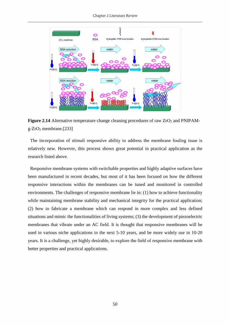
Chapter 2 Literature Review
50
Figure 2.14 Alternative temperature change cleaning procedures of raw ZrO2 and PNIPAM-
g-ZrO2 membrane.[233]
The incorporation of stimuli responsive ability to address the membrane fouling issue is
relatively new. However, this process shows great potential in practical application as the
research listed above.
Responsive membrane systems with switchable properties and highly adaptive surfaces have
been manufactured in recent decades, but most of it has been focused on how the different
responsive interactions within the membranes can be tuned and monitored in controlled
environments. The challenges of responsive membrane lie in: (1) how to achieve functionality
while maintaining membrane stability and mechanical integrity for the practical application;
(2) how to fabricate a membrane which can respond in more complex and less defined
situations and mimic the functionalities of living systems; (3) the development of piezoelectric
membranes that vibrate under an AC field. It is thought that responsive membranes will be
used in various niche applications in the next 5-10 years, and be more widely use in 10-20
years. It is a challenge, yet highly desirable, to explore the field of responsive membrane with
better properties and practical applications.
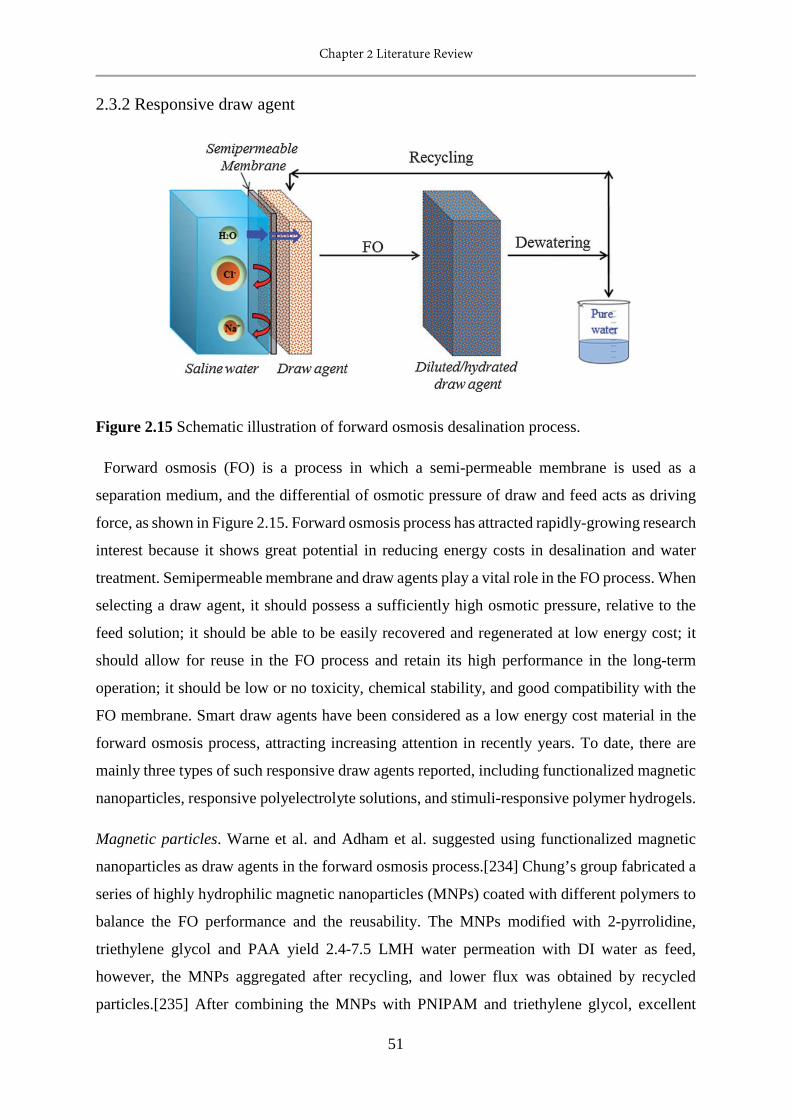
Chapter 2 Literature Review
51
2.3.2 Responsive draw agent
Figure 2.15 Schematic illustration of forward osmosis desalination process.
Forward osmosis (FO) is a process in which a semi-permeable membrane is used as a
separation medium, and the differential of osmotic pressure of draw and feed acts as driving
force, as shown in Figure 2.15. Forward osmosis process has attracted rapidly-growing research
interest because it shows great potential in reducing energy costs in desalination and water
treatment. Semipermeable membrane and draw agents play a vital role in the FO process. When
selecting a draw agent, it should possess a sufficiently high osmotic pressure, relative to the
feed solution; it should be able to be easily recovered and regenerated at low energy cost; it
should allow for reuse in the FO process and retain its high performance in the long-term
operation; it should be low or no toxicity, chemical stability, and good compatibility with the
FO membrane. Smart draw agents have been considered as a low energy cost material in the
forward osmosis process, attracting increasing attention in recently years. To date, there are
mainly three types of such responsive draw agents reported, including functionalized magnetic
nanoparticles, responsive polyelectrolyte solutions, and stimuli-responsive polymer hydrogels.
Magnetic particles. Warne et al. and Adham et al. suggested using functionalized magnetic
nanoparticles as draw agents in the forward osmosis process.[234] Chung’s group fabricated a
series of highly hydrophilic magnetic nanoparticles (MNPs) coated with different polymers to
balance the FO performance and the reusability. The MNPs modified with 2-pyrrolidine,
triethylene glycol and PAA yield 2.4-7.5 LMH water permeation with DI water as feed,
however, the MNPs aggregated after recycling, and lower flux was obtained by recycled
particles.[235] After combining the MNPs with PNIPAM and triethylene glycol, excellent

Chapter 2 Literature Review
52
stability and recycle capacity were obtained, and the flux was maintained after 5 cycles,
although the FO flux is only 1.2 LMH when DI water used as feed.[236] In future work, they
modified MNPs with PAA or PAA/PNIPAM, which generated 2.6-5.5 LMH water flux when
DI water as feed, with constant fluxes after recycling.[237] Regardless of the low water flux,
the long-term stability and large-scale production of magnetic nanoparticles still needs to be
addressed.
Responsive polyelectrolytes. The pH sensitive polyelectrolyte (poly (sodium acrylate), PSA)
has been reported in the forward osmosis process by Chung’s group. The water flux generated
by the 0.6 g/ml PSA 1200 solution was ~5 LMH. However, the diluted PSA solution was
recovered by ultrafiltration process under 10 bar, it is an energy-consuming process.[238]
Linear poly (N-isopropyl acrylamide-co-sodium acrylate) (PNIPAM-SA) was also used as
draw agent. Even though thermo-responsive polyelectrolytes can be easily recovered by heat
ultrafiltration at 2 bar, the flux generated was only 0.35 LMH owing to the low proportion of
ionic groups in the polyelectrolyte network (4 wt. % SA).[148] Cai et al. reported a CO2
switchable dual responsive polymers as a forward osmosis draw solute.[239] After purging
with CO2, the low molecular weight responsive polymer (poly [2-(dimethylamino) ethyl
methacrylate], PDMAEMA) became polyelectrolytes with high osmolality and used as draw
solutes for seawater desalination. When PDMAEMA with a molecular weight of 4000 g/mol
was used, the 0.6 g/g polymer solution generated > 2 LMH water flux against seawater as feed.
After removal of CO2 by purging inert gas, these polymer precipitated above their LCST,
realizing the water recovery and draw solute reuse. Recently, a thermo-responsive copolymer,
poly (sodium styrene-4-sulfonate-co-N-isopropylacrylamide) (PSSS-PNIPAM), was
employed as draw solute in forward osmosis for seawater desalination. A water flux of 4 LMH
has been obtained with simulated seawater as the feed solution; the draw solution was
regenerated with membrane distillation (MD) at a temperature above the lower critical solution
temperature. [240] A series of oligomeric poly (tetrabutylphosphonium styrenesulfonate)
(PSSP) were also evaluated as FO draw solutes.[241] When 20 wt. % polymer solution was
used as draw solute and 2000 ppm NaCl solution used as a feed, the water flux was about 6
LMH. More than 99.5% of PSSPs in diluted solutions can be recovered by only thermal
treatment and without any further significant decrease in the water permeation flux. More
recently, ionic liquids have also been explored as a responsive draw agent.[242] Although the
separation of polyelectrolytes from water has been investigated, little attention has been paid
Chapter 2 Literature Review
53
to the quality of the water product. The polyelectrolytes are likely to contaminate the product
water, especially the polymers with small molecular weight.
Responsive hydrogels. Cross-linked poly (N-isopropyl acrylamide) (PNIPAM) and its
copolymer have been applied as smart draw agents in forward osmosis water treatment. Cross-
linked poly (N-isopropyl acrylamide) (PNIPAM) is a classical thermo-sensitive hydrogel with
both hydrophilic groups and hydrophobic groups in the network, which switches between
hydrophilicity and hydrophobicity at temperatures lower and higher than its lower critical
solution temperature (LCST). In 2011, our group successfully demonstrated the feasibility by
using smart draw agents in FO desalination for the first time. In the first study, PAM
(polyacrylamide), PSA, PNIPAM, and PNIPAM-co-SA hydrogels were used for purifying
brackish water (2000 ppm NaCl solution). The result showed that the FO water flux increased
with increasing ionic group content in the network, and decreased with increasing time; the
water recovery increased with increasing amount of NIPAM and higher water content of the
hydrogels. The average water flux of PNIPAM-co-SA in the first hour was 0.55 LMH, the
swollen hydrogel with 66.7 % water content released 17 % water after 2 minutes dewatering at
50 °C.[234] To improving the FO performance, we fabricated a hydrogel and carbon particles
composite, the water flux of composite PSA-NIPAM-C in the first 0.5 hour was 0.77 LMH and
almost 100 % water was recovered after 1 h exposure to solar irradiation of 1 kWm-2.[243] The
hydrogels were also composited with reduced graphene oxide (rGO) to improve the swelling
properties. When the water flux was tested using deionized water as the feed solution, the
incorporation of 1.2 wt. % rGO led to an increase in the water flux by 164 % and 325 % for
the PSA composite and PSA-NIPAM composite, respectively. Adding small amounts of rGO
also increased the water recovery by a factor of two in the solar dewatering process.[244] In
addition, in other work the hydrogel had magnetic nanoparticles incorporated. The result
indicated that the magnetic heating was an effective and rapid method for dewatering of
hydrogels. Significantly enhanced liquid water recovery (53 %) was achieved under magnetic
heating, as opposed to only around 7 % liquid water recovery obtained via convection
heating.[245] In addition to these factors, the effect of particle size on the performance of FO
process has been investigated. The result showed that reducing the hydrogel particle size
resulted in an increase in the rate of swelling, generating higher water flux.[246] The dual-
functionality hydrogels consist of a water-absorptive layer (PSA-NIPAM particles) and a
dewatering layer (PNIPAM particles) were applied to improve the dewatering rate. The
dewatering flux rose from 10 to 25 LMH when the solar concentrator increased the input energy
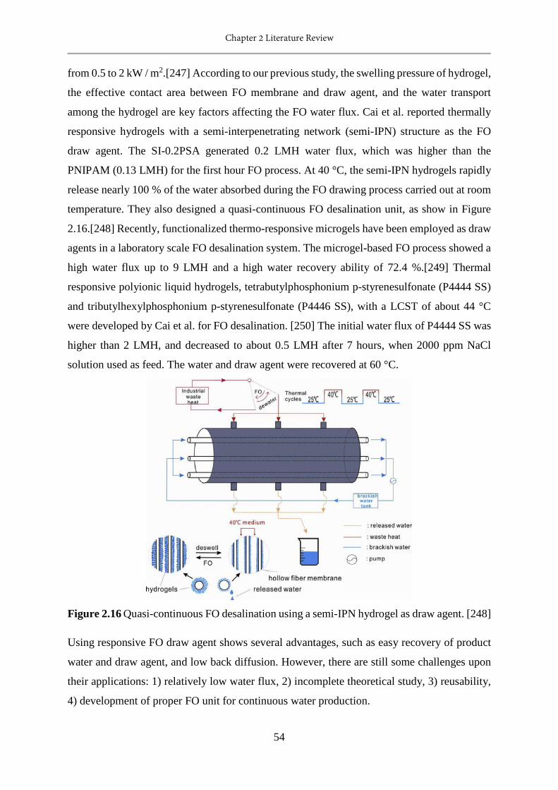
Chapter 2 Literature Review
54
from 0.5 to 2 kW / m2.[247] According to our previous study, the swelling pressure of hydrogel,
the effective contact area between FO membrane and draw agent, and the water transport
among the hydrogel are key factors affecting the FO water flux. Cai et al. reported thermally
responsive hydrogels with a semi-interpenetrating network (semi-IPN) structure as the FO
draw agent. The SI-0.2PSA generated 0.2 LMH water flux, which was higher than the
PNIPAM (0.13 LMH) for the first hour FO process. At 40 °C, the semi-IPN hydrogels rapidly
release nearly 100 % of the water absorbed during the FO drawing process carried out at room
temperature. They also designed a quasi-continuous FO desalination unit, as show in Figure
2.16.[248] Recently, functionalized thermo-responsive microgels have been employed as draw
agents in a laboratory scale FO desalination system. The microgel-based FO process showed a
high water flux up to 9 LMH and a high water recovery ability of 72.4 %.[249] Thermal
responsive polyionic liquid hydrogels, tetrabutylphosphonium p-styrenesulfonate (P4444 SS)
and tributylhexylphosphonium p-styrenesulfonate (P4446 SS), with a LCST of about 44 °C
were developed by Cai et al. for FO desalination. [250] The initial water flux of P4444 SS was
higher than 2 LMH, and decreased to about 0.5 LMH after 7 hours, when 2000 ppm NaCl
solution used as feed. The water and draw agent were recovered at 60 °C.
Figure 2.16 Quasi-continuous FO desalination using a semi-IPN hydrogel as draw agent. [248]
Using responsive FO draw agent shows several advantages, such as easy recovery of product
water and draw agent, and low back diffusion. However, there are still some challenges upon
their applications: 1) relatively low water flux, 2) incomplete theoretical study, 3) reusability,
4) development of proper FO unit for continuous water production.
Chapter 2 Literature Review
55
2.3.3 Responsive adsorbent
Adsorption is one of the most widely applied water treatment technologies due to their simple
operation, relatively low cost, high efficiency, flexibility, and insensitivity to toxic substance.
Developing regenerable, low cost, and environmentally-friendly adsorbents are always desired
in view of practical water treatment applications. Stimuli responsive materials have been
incorporated into adsorption materials for regeneration, selective adsorption and high
adsorption capacity. To date, responsive hydrogel, magnetic composite and responsive material
modified particles are the main responsive adsorbent studied and applied.
Responsive hydrogel. Shirsath et al. synthesize a poly (acrylic acid)-bentonite-FeCo (PAA-B-
FeCo) hydrogel nanocomposite as a responsive adsorbent for removal of organic pollutant from
water.[251] Temperature and pH affect the adsorption performance of PAA-B-FeCo that the
optimum condition was operated at 35 °C and pH 11. Aburto et al. synthesized a stimuli
responsive chitosan hydrogel (IHDBTS) by crosslinking of chitosan with glutaraldehyde in the
presence of dibenzothiophene sulfone (DBTS) as template.[252] This hydrogel is temperature
responsive, with a LCST of 50 °C. IHDBTS selectively adsorbed DBTS due to the
conformational memory at the temperature of LCST. Yamashita et al. prepared an
interpenetrating network (IPN) gel of PNIPAM and PSA for heavy metal ions removal.[253]
The IPN gel adsorbed Cu2+ ion below LCST but not above. However, at elevated temperature,
water was released from hydrogel but Cu2+ ions still trapped inside. Desorption of heavy metal
ions can be triggered by acidic treatment. Lu et al. prepared sodium alginate beads by post
crosslinking sodium alginate with glutaraldehyde in the presence of acetic acid and
hydrochloric acid in acetone.[254] The sodium alginate beads could adsorb cationic dye and
heavy metal ions, with and adsorption capacity of Cu2+, Ag+, Fe3+ and methylene blue were 55,
83, 136, 573 mg/g, respectively. These adsorption performances were affected by the solution
pH. The adsorption capacity of sodium alginate beads in the neutral state was twice as high as
that in the acidic state, because the high pH dissociated carboxylic ions to provide high charge
density and it interrupted the hydrogen bonding interaction. Nanostructured zwitterionic (ZI)
hybrid hydrogel was prepared with monomer N, N-dimethyl-N-methacryloyloxyethyl-N-(3-
sulfopropyl) ammonium (DMMSA) for protein separation of Lys and BSA.[255] This pH
responsive hydrogel showed a minimum adsorption of Lys at pH 10.7, and that of BSA was
observed at pH 4.8, indicating the feasibility of protein separation. Adsorption and desorption
carried out in pH 6.0 buffer solution revealed nice cycle performance.
Chapter 2 Literature Review
56
Magnetic composite particles. The magnetic composite particles have an advantage of easy
collection / separation from solution by giving magnetic field. However, it is not responsible
for the regeneration of adsorbent. Iron oxide has been incorporated into activated carbon to
introduce the magnetic ability for easy collection. The study of Oliveira et al. showed that the
composite exhibited same high adsorption capacities for phenol, chloroform, chlorobenzene
and drimaren red dye in aqueous solution. Iron oxide has also been introduced to clay (bentonite)
to obtain a magnetic composite for removing divalent metal ions in water, with adsorption
capacities in a range of 40-75 mmol/g for Ni2+, Cu2+, Cd2+ and Zn2+.[256] Xie et al. introduced
a facile method to prepare Fe3O4 @ polydopamine (PDA)-Ag core-shell microspheres for fast
adsorption of Methylene blue (MB).[257] The as-prepared Fe3O4 @ PDA-Ag exhibited good
acid stability, high cyclic stability, magnetic separation, fast regeneration ability by using
NaBH4 as the desorption agent. Magnetic Fe3O4 @ carbon nanofibres with hierarchical porous
fabricated by using electrospun polyacrylonitrile / polybenzoxazing nanofibres as a composite
carbon source exhibited efficient adsorption for organic dyes.[258] The Fe3O4 @ CNFs showed
fast dyes adsorption kinetics and magnetic separation from water in a minute. Magnetic Fe3O4
@ graphene composite (FGC) was also evaluated as adsorbent for methylene blue and Congo
red removal.[259] The maximum adsorption capacities of MB and CR on FGC were 45 and 34
mg/g, respectively. Iron oxide / carbon nanotubes magnetic composites were also fabricated
for heavy metal removal, such as chromium, europium, Ni2+ and Sr2+.[260] What’s more,
natural polymer such as alginate and chitosan has already been composited with iron oxide,
and applied for metal ions adsorption.[261, 262]
Surface modified particles. A pH- and temperature- responsive magnetic composite (poly (N-
isopropyl acrylamide) grafted chitosan/Fe3O4 composite particles, CN-MCP) was fabricated
by Yang et al. as a high selective adsorbent for nonylphenol in water.[263] CN-MCP showed
high adsorption capacity for removing nonylphenol: 1) 123 mg/g at pH 9 and 20 °C due to the
charge attraction and binding between CN-MCP and nonylphenol; 2) 116 mg/g at pH 5 and
40 °C, because of their hydrophobic interaction. CN-MCP exhibited fast and highly efficient
antibiotics adsorption, high stability, reusability and easy separation Liu et al. manufactured a
pH- responsive and magnetic composite composed of graphene oxide (GO)/nanoscale zero-
valent iron (nZVI) was used for antibiotics adsorption and oxidation degradation.[264]. After
removal of antibiotics, the GO/nZVI composite was put into alkaline solution (pH>9) for
adsorbent regeneration and antibiotics degradation by ozonization. Ammonium-functionalized
hollow polymer particles (HPP-NH3+) developed by Qin et al. ware studied as a pH-responsive
Chapter 2 Literature Review
57
adsorbent for selective removal of acid dye in water.[265] With the solution pH decreased from
9 to 2, the adsorption capacity of HPP- NH3+ increased significantly from 59 to 406 mg/g,
demonstrating the feasibility of easy regeneration under mild condition (pH 10 weak alkaline
solution). The dye removal efficiency can be still as high as above 98 % after 5 adsorption –
desorption cycles. Xu et al. fabricated a thermal responsive magnetic molecularly imprinted
polymers (TMMIPs) by coating magnetic nanoparticle cores with thermo-responsive polymer
and applied it for selective removal of sulfamethazine (SMZ) in aquatic environments.[266]
TMMIPs could be collected by magnetic field and regenerated by changing the temperature of
aqueous solution at 45 °C. A thermo-responsive composite synthesized by grafting poly
(oligoethylene glycol) methacrylate (POEGMA) on cationic agarose adsorbent was used for
size selective protein adsorption.[267] The adsorption capacity of POEGMA-g-Q increased
with increasing temperature and reached maximum value around their LCST. This adsorbent
has also been demonstrated for size selective adsorption upon temperature changes. In Dong’s
study, thermosensitive polymer composed of 4-vinylpyridine and NIPAM was imprinted on
hollow porous polystyrene particles for selective recognition, controlled adsorption and release
of bisphenol A (BPA).[268] The adsorption capacity of T-MIPs was temperature related,
higher under 33 °C, and decreased rapidly at 50 °C. These composite particles were employed
for removal of BPA from seawater and yogurt samples.
In addition, MOF-based adsorbents have been studied for water treatment such as removal of
metal ions, toxic anions and dye. They showed remarkable adsorption capacity and superior
adsorption kinetics, owing to their high surface area and accessibility of adsorption sites.
Recently, photo-responsive metal organic frameworks have been fabricated for on command
cargo release in water, indicating that responsive MOF-based possesses great potential for
efficient and environmental friendly water treatment.[269]
Responsive adsorbents have been intensively studied in the past several decades, primarily
magnetic responsive adsorbent for easy collection and separation from aqueous solution. Other
responsive materials introduced are mainly used to tune the wettability and adhesion of
different species for the selective adsorption purpose. The regeneration of adsorbent by stimuli
responsiveness can significantly reduce the cost of adsorption process. The development of
stimuli-responsive regenerable adsorbents with high adsorption and proper reusability are
highly desirable.

Chapter 2 Literature Review
58
2.4 Summary
Increasing population and improper industrialization practices have led to detrimental surface
and underground water contamination at an unprecedented rate, endangering human health.
Conventional water treatment systems can address many of these problems, but they are always
chemically, operationally and energetically intensive, and require considerable infusion of
capital and time, which precludes their use in much of the world, especially where water is
really needed. There is a pressing need to develop a more effective, lower-cost, robust methods
for water treatment and purification, without further stressing the environment by the treatment
itself.
Advanced water treatment technologies have been developed to deal with this situation, they
are mainly advanced oxidation process, biological treatment, adsorption / ion exchange process
and membrane separation process. These advanced water treatment technologies deal with a
range of contaminants that conventional water treatment system cannot address, such as
persistence organic substances, toxic / heavy metals and radioactive metals, or deal with it in a
more efficient way. The previous investigations have demonstrated the feasibility of these
technologies and promoted their industry applications. However, further developments are
needed to overcome the problems encountered, such as developing robust materials, stabilizing
the treatment performance for real applications, maintaining the reusability, building practical
and reliable systems and so on.
Stimuli responsive materials that change their physical and / or chemical properties in
response to environmental stimuli, have been recently incorporated into the water treatment
materials and include responsive membranes, responsive forward osmosis draw agents and
responsive adsorbents. These responsive water treatment materials show great potential to
overcome many problems found on the advanced water treatment technologies, such as
membrane fouling and the energetic and chemical regeneration. The main use of
responsiveness in membranes are controlling separation and addressing fouling. By the
oscillation of chain conformation and wettability, selective permeation, tunable permeation
flux and on-off state management can be achieved, as well as the releasing of adsorbed foulants.
Responsive draw agents that release water and achieve regeneration by giving environmental
stimuli, are very promising for reducing energy consumption of the forward osmosis process.
Responsive adsorbents show great potential in practical application because of easy collection,
easy regeneration and accessibility of raw adsorbent modification. However, the development
Chapter 2 Literature Review
59
of these three kinds of responsive materials are still in an initial stage, with further development
for advanced functionalities and applications desired for achieving a smart water treatment
system with highly improved treatment efficiency and / or biomimetic nature.
In the following chapters, thermo-responsive oil water separation membrane (Chapter 3),
responsive microfibres-hydrogel composite draw agent (Chapter 4 & 5), and thermo-
responsive MOF-based adsorbent (Chapter 6) are fabricated and evaluated for water processing.
2.5 References
[1] S. Diop, P. M'mayi, D. Lisbjerg, R. Johnstone, Vital water graphics: an overview of the
state of the world's fresh and marine waters, UNEP/Earthprint, 2002.
[2] C.J. Vörösmarty, P.B. McIntyre, M.O. Gessner, D. Dudgeon, A. Prusevich, P. Green, S.
Glidden, S.E. Bunn, C.A. Sullivan, C.R. Liermann, Global threats to human water security and
river biodiversity, Nature, 467 (2010) 555-561.
[3] R.P. Schwarzenbach, T. Egli, T.B. Hofstetter, U. von Gunten, B. Wehrli, Global water
pollution and human health, Annual Review of Environment and Resources, 35 (2010) 109-
136.
[4] F.R. Rijsberman, Water scarcity: fact or fiction?, Agricultural water management, 80 (2006)
5-22.
[5] R.E. Galt, Beyond the circle of poison: significant shifts in the global pesticide complex,
1976–2008, Global Environmental Change, 18 (2008) 786-799.
[6] Y. Chen, F. Parvez, M. Gamble, T. Islam, A. Ahmed, M. Argos, J.H. Graziano, H. Ahsan,
Arsenic exposure at low-to-moderate levels and skin lesions, arsenic metabolism, neurological
functions, and biomarkers for respiratory and cardiovascular diseases: review of recent findings
from the Health Effects of Arsenic Longitudinal Study (HEALS) in Bangladesh, Toxicology
and applied pharmacology, 239 (2009) 184-192.
[7] M. Amini, K.C. Abbaspour, M. Berg, L. Winkel, S.J. Hug, E. Hoehn, H. Yang, C.A.
Johnson, Statistical modeling of global geogenic arsenic contamination in groundwater,
Environmental science & technology, 42 (2008) 3669-3675.
[8] L. Giusti, A review of waste management practices and their impact on human health,
Waste management, 29 (2009) 2227-2239.
[9] D.L. Baun, T.H. Christensen, Speciation of heavy metals in landfill leachate: a review,
Waste management & research, 22 (2004) 3-23.
Chapter 2 Literature Review
60
[10] T.H. Christensen, P. Kjeldsen, P.L. Bjerg, D.L. Jensen, J.B. Christensen, A. Baun, H.-J.
Albrechtsen, G. Heron, Biogeochemistry of landfill leachate plumes, Applied geochemistry,
16 (2001) 659-718.
[11] D.W. Kolpin, E.T. Furlong, M.T. Meyer, E.M. Thurman, S.D. Zaugg, L.B. Barber, H.T.
Buxton, Pharmaceuticals, hormones, and other organic wastewater contaminants in US streams,
1999− 2000: A national reconnaissance, Environmental science & technology, 36 (2002) 1202-
1211.
[12] T. Ternes, A. Joss, Human pharmaceuticals, hormones and fragrances, IWA publishing,
2007.
[13] M.A. Montgomery, M. Elimelech, Water and sanitation in developing countries: including
health in the equation, Environ. Sci. Technol, 41 (2007) 17-24.
[14] M.A. Shannon, P.W. Bohn, M. Elimelech, J.G. Georgiadis, B.J. Marinas, A.M. Mayes,
Science and technology for water purification in the coming decades, Nature, 452 (2008) 301-
310.
[15] P.H. Gleick, Dirty-water: Estimated Deaths from Water-related Diseases 2000-2020,
Citeseer, 2002.
[16] P. Vesilind, Wastewater treatment plant design, IWA publishing, 2004.
[17] C.R. Schulz, D.A. Okun, D. Donaldson, J. Austin, Surface water treatment for
communities in developing countries, (1992).
[18] M. Hammer, J.(1975). Water and Waste Water Technology, in, John Wiley.
[19] E. Washington, DC:“Primer for Municipal Waste water Treatment Systems.” Document
no, in, EPA 832-R-04-001, 2004.
[20] W.J. Weber, Physicochemical processes for water quality control, Wiley Interscience,
1972.
[21] K. Christman, The history of chlorine, Water World, 14 (1998) 66-67.
[22] C. HOWLETT, CHLORINE-THE ISSUE, THE REALITY AND THE SOLUTION, in:
ABSTRACTS OF PAPERS OF THE AMERICAN CHEMICAL SOCIETY, AMER
CHEMICAL SOC PO BOX 57136, WASHINGTON, DC 20037-0136, 1995, pp. 120-ENVR.
[23] S. Parsons, Advanced oxidation processes for water and wastewater treatment, IWA
publishing, 2004.
[24] R. Andreozzi, V. Caprio, A. Insola, R. Marotta, Advanced oxidation processes (AOP) for
water purification and recovery, Catalysis today, 53 (1999) 51-59.
[25] D.G. Rao, R. Senthilkumar, J.A. Byrne, S. Feroz, Wastewater treatment: advanced
processes and technologies, CRC Press, 2012.
Chapter 2 Literature Review
61
[26] J.J. Pignatello, E. Oliveros, A. MacKay, Advanced oxidation processes for organic
contaminant destruction based on the Fenton reaction and related chemistry, Critical reviews
in environmental science and technology, 36 (2006) 1-84.
[27] H. Suty, C. De Traversay, M. Cost, Applications of advanced oxidation processes: present
and future, Water Science and Technology, 49 (2004) 227-233.
[28] J.R. Bolton, C.A.C. Cotton, The ultraviolet disinfection handbook, American Water
Works Association, 2011.
[29] G. Ruppert, R. Bauer, G. Heisler, UV-O3, UV-H2O2, UV-TiO2 and the photo-Fenton
reaction-comparison of advanced oxidation processes for wastewater treatment, Chemosphere,
28 (1994) 1447-1454.
[30] J.C. Kruithof, P.C. Kamp, B.J. Martijn, UV/H2O2 treatment: A practical solution for
organic contaminant control and primary disinfection, Ozone: Science and Engineering, 29
(2007) 273-280.
[31] S.R. Cater, M.I. Stefan, J.R. Bolton, A. Safarzadeh-Amiri, UV/H2O2 treatment of methyl
tert-butyl ether in contaminated waters, Environmental science & technology, 34 (2000) 659-
662.
[32] H. Shemer, Y.K. Kunukcu, K.G. Linden, Degradation of the pharmaceutical
metronidazole via UV, Fenton and photo-Fenton processes, Chemosphere, 63 (2006) 269-276.
[33] J. Chen, L. Zhu, Heterogeneous UV-Fenton catalytic degradation of dyestuff in water with
hydroxyl-Fe pillared bentonite, Catalysis Today, 126 (2007) 463-470.
[34] J. Chen, L. Zhu, Catalytic degradation of Orange II by UV-Fenton with hydroxyl-Fe-
pillared bentonite in water, Chemosphere, 65 (2006) 1249-1255.
[35] A. Chin, P. Bérubé, Removal of disinfection by-product precursors with ozone-UV
advanced oxidation process, Water Research, 39 (2005) 2136-2144.
[36] M.S. Lucas, J.A. Peres, G.L. Puma, Treatment of winery wastewater by ozone-based
advanced oxidation processes (O 3, O 3/UV and O 3/UV/H 2 O 2) in a pilot-scale bubble
column reactor and process economics, Separation and Purification Technology, 72 (2010)
235-241.
[37] J. Verhoeven, Glossary of terms used in photochemistry (IUPAC Recommendations 1996),
Pure and Applied Chemistry, 68 (1996) 2223-2286.
[38] M.N. Chong, B. Jin, C.W. Chow, C. Saint, Recent developments in photocatalytic water
treatment technology: a review, Water research, 44 (2010) 2997-3027.
[39] M.A. Lazar, S. Varghese, S.S. Nair, Photocatalytic water treatment by titanium dioxide:
recent updates, Catalysts, 2 (2012) 572-601.

Chapter 2 Literature Review
62
[40] A. Mills, S. Le Hunte, An overview of semiconductor photocatalysis, Journal of
photochemistry and photobiology A: Chemistry, 108 (1997) 1-35.
[41] S. Malato, P. Fernández-Ibáñez, M.I. Maldonado, J. Blanco, W. Gernjak,
Decontamination and disinfection of water by solar photocatalysis: recent overview and trends,
Catalysis Today, 147 (2009) 1-59.
[42] Y. Shiying, W. Ping, Y. Xin, W. Guang, W. ZHANG, S. Liang, A novel advanced
oxidation process to degrade organic pollutants in wastewater: Microwave-activated persulfate
oxidation, Journal of environmental sciences, 21 (2009) 1175-1180.
[43] T. Velegraki, I. Poulios, M. Charalabaki, N. Kalogerakis, P. Samaras, D. Mantzavinos,
Photocatalytic and sonolytic oxidation of acid orange 7 in aqueous solution, Applied Catalysis
B: Environmental, 62 (2006) 159-168.
[44] H. Destaillats, A. Colussi, J.M. Joseph, M.R. Hoffmann, Synergistic effects of sonolysis
combined with ozonolysis for the oxidation of azobenzene and methyl orange, Journal of
Physical Chemistry A, 104 (2000) 8930-8935.
[45] P.E. Savage, Organic chemical reactions in supercritical water, Chemical reviews, 99
(1999) 603-622.
[46] H. Barner, C. Huang, T. Johnson, G. Jacobs, M. Martch, W. Killilea, Supercritical water
oxidation: an emerging technology, Journal of hazardous materials, 31 (1992) 1-17.
[47] Z. Aksu, Application of biosorption for the removal of organic pollutants: a review,
Process Biochemistry, 40 (2005) 997-1026.
[48] B. Volesky, Biosorbents for metal recovery, Trends in Biotechnology, 5 (1987) 96-101.
[49] K. Vijayaraghavan, M.W. Lee, Y.-S. Yun, Evaluation of fermentation waste
(Corynebacterium glutamicum) as a biosorbent for the treatment of nickel (II)-bearing
solutions, Biochemical Engineering Journal, 41 (2008) 228-233.
[50] B. Volesky, Z. Holan, Biosorption of heavy metals, Biotechnology progress, 11 (1995)
235-250.
[51] F. Veglio, F. Beolchini, Removal of metals by biosorption: a review, Hydrometallurgy,
44 (1997) 301-316.
[52] S. Choi, Y.-S. Yun, Lead biosorption by waste biomass of Corynebacterium glutamicum
generated from lysine fermentation process, Biotechnology letters, 26 (2004) 331-336.
[53] Z. Holan, B. Volesky, Biosorption of lead and nickel by biomass of marine algae,
Biotechnology and Bioengineering, 43 (1994) 1001-1009.
[54] Z. Holan, B. Volesky, I. Prasetyo, Biosorption of cadmium by biomass of marine algae,
Biotechnology and bioengineering, 41 (1993) 819-825.
Chapter 2 Literature Review
63
[55] H. An, B. Park, D. Kim, Crab shell for the removal of heavy metals from aqueous solution,
Water Research, 35 (2001) 3551-3556.
[56] M.Y. Lee, K.J. Hong, T. Kajiuchi, J.W. Yang, Determination of the efficiency and removal
mechanism of cobalt by crab shell particles, Journal of Chemical Technology and
Biotechnology, 79 (2004) 1388-1394.
[57] M.-Y. Lee, S.-H. Lee, H.-J. Shin, T. Kajiuchi, J.-W. Yang, Characteristics of lead removal
by crab shell particles, Process biochemistry, 33 (1998) 749-753.
[58] K. Vijayaraghavan, J.R. Jegan, K. Palanivelu, M. Velan, Nickel recovery from aqueous
solution using crab shell particles, Adsorption Science & Technology, 23 (2005) 303-312.
[59] K. Vijayaraghavan, K. Palanivelu, M. Velan, Biosorption of copper (II) and cobalt (II)
from aqueous solutions by crab shell particles, Bioresource technology, 97 (2006) 1411-1419.
[60] K. Vijayaraghavan, H.Y.N. Winnie, R. Balasubramanian, Biosorption characteristics of
crab shell particles for the removal of manganese (II) and zinc (II) from aqueous solutions,
Desalination, 266 (2011) 195-200.
[61] G. Dönmez, Z. Aksu, The effect of copper (II) ions on the growth and bioaccumulation
properties of some yeasts, Process Biochemistry, 35 (1999) 135-142.
[62] Z. Aksu, G. Dönmez, The use of molasses in copper (II) containing wastewaters: effects
on growth and copper (II) bioaccumulation properties of Kluyveromyces marxianus, Process
Biochemistry, 36 (2000) 451-458.
[63] Z. Aksu, G. Dönmez, Combined effects of molasses sucrose and reactive dye on the
growth and dye bioaccumulation properties of Candida tropicalis, Process Biochemistry, 40
(2005) 2443-2454.
[64] S.D. Cunningham, D.W. Ow, Promises and prospects of phytoremediation, Plant
physiology, 110 (1996) 715.
[65] M.N. Vara Prasad, H.M. de Oliveira Freitas, Metal hyperaccumulation in plants:
biodiversity prospecting for phytoremediation technology, Electronic Journal of
Biotechnology, 6 (2003) 285-321.
[66] M. Benka-Coker, A. Olumagin, Waste drilling-fluid-utilising microorganisms in a tropical
mangrove swamp oilfield location, Bioresource technology, 53 (1995) 211-215.
[67] O.O. Amund, C. Igiri, Biodegradation of petroleum hydrocarbons under tropical estuarine
conditions, World Journal of Microbiology and Biotechnology, 6 (1990) 255-262.
[68] M.P. Díaz, K.G. Boyd, S.J. Grigson, J.G. Burgess, Biodegradation of crude oil across a
wide range of salinities by an extremely halotolerant bacterial consortium MPD‐M,
immobilized onto polypropylene fibers, Biotechnology and bioengineering, 79 (2002) 145-153.

Chapter 2 Literature Review
64
[69] A. Dąbrowski, Adsorption—from theory to practice, Advances in colloid and interface
science, 93 (2001) 135-224.
[70] S.D. Alexandratos, Ion-exchange resins: a retrospective from industrial and engineering
chemistry research, Industrial and Engineering Chemistry Research, 48 (2009) 388.
[71] W.L. McCabe, J.C. Smith, P. Harriott, Unit operations of chemical engineering, McGraw-
Hill New York, 1993.
[72] A. Anson, J. Jagiello, J.B. Parra, M.L. Sanjuan, A.M. Benito, W.K. Maser, M.T. Martínez,
Porosity, surface area, surface energy, and hydrogen adsorption in nanostructured carbons, The
Journal of Physical Chemistry B, 108 (2004) 15820-15826.
[73] S.J. Gregg, K.S.W. Sing, H. Salzberg, Adsorption surface area and porosity, Journal of
The Electrochemical Society, 114 (1967) 279C-279C.
[74] J. Rouquerol, F. Rouquerol, P. Llewellyn, G. Maurin, K.S. Sing, Adsorption by powders
and porous solids: principles, methodology and applications, Academic press, 2013.
[75] F. Rodríguez‐Reinoso, Production and applications of activated carbons, Handbook of
porous solids, (2002) 1766-1827.
[76] H. Marsh, F.R. Reinoso, Activated carbon, Elsevier, 2006.
[77] V.J. Inglezakis, S.G. Poulopoulos, Adsorption, ion exchange and catalysis, Elsevier, 2006.
[78] S.-W. Bian, J. Baltrusaitis, P. Galhotra, V.H. Grassian, A template-free, thermal
decomposition method to synthesize mesoporous MgO with a nanocrystalline framework and
its application in carbon dioxide adsorption, Journal of Materials Chemistry, 20 (2010) 8705-
8710.
[79] M. Bhagiyalakshmi, J.Y. Lee, H.T. Jang, Synthesis of mesoporous magnesium oxide: its
application to CO 2 chemisorption, International Journal of Greenhouse Gas Control, 4 (2010)
51-56.
[80] J. Rouquerol, K.S. Sing, P. Llewellyn, Adsorption by metal oxides, Adsorption by
Powders and Porous Solids: Principles, Methodology and Applications, (2013) 393.
[81] R.M. Cornell, U. Schwertmann, The iron oxides: structure, properties, reactions,
occurrences and uses, John Wiley & Sons, 2003.
[82] H. Van Olphen, Thermodynamics of interlayer adsorption of water in clays. I.—Sodium
vermiculite, Journal of Colloid Science, 20 (1965) 822-837.
[83] A.R. Khokhlov, Physics of finely divided matter, Physics-Uspekhi, 30 (1987) 196-196.
[84] F. Bergaya, The meaning of surface area and porosity measurements of clays and pillared
clays, Journal of Porous Materials, 2 (1995) 91-96.
Chapter 2 Literature Review
65
[85] A. Günay, B. Ersoy, S. Dikmen, A. Evcin, Investigation of equilibrium, kinetic,
thermodynamic and mechanism of Basic Blue 16 adsorption by montmorillonitic clay,
Adsorption, 19 (2013) 757-768.
[86] E. Errais, J. Duplay, M. Elhabiri, M. Khodja, R. Ocampo, R. Baltenweck-Guyot, F.
Darragi, Anionic RR120 dye adsorption onto raw clay: Surface properties and adsorption
mechanism, Colloids and Surfaces A: Physicochemical and Engineering Aspects, 403 (2012)
69-78.
[87] J.U.K. Oubagaranadin, Z. Murthy, Adsorption of divalent lead on a montmorillonite− illite
type of clay, Industrial & Engineering Chemistry Research, 48 (2009) 10627-10636.
[88] A. Baiker, H. Blaser, G. Ertl, H. Knözinger, J. Weitkamp, Handbook of Heterogeneous
Catalysis, Ertl, G., Knözinger, H., Weitkamp, J., Eds, (1997) 2422.
[89] C. Kresge, M. Leonowicz, W. Roth, J. Vartuli, J. Beck, Ordered mesoporous molecular
sieves synthesized by a liquid-crystal template mechanism, nature, 359 (1992) 710-712.
[90] D. Zhao, J. Feng, Q. Huo, N. Melosh, G.H. Fredrickson, B.F. Chmelka, G.D. Stucky,
Triblock copolymer syntheses of mesoporous silica with periodic 50 to 300 angstrom pores,
science, 279 (1998) 548-552.
[91] X. Zhao, X. Bu, T. Wu, S.-T. Zheng, L. Wang, P. Feng, Selective anion exchange with
nanogated isoreticular positive metal-organic frameworks, Nature communications, 4 (2013).
[92] A.J. Howarth, M.J. Katz, T.C. Wang, A.E. Platero-Prats, K.W. Chapman, J.T. Hupp, O.K.
Farha, High Efficiency Adsorption and removal of selenate and selenite from water using
metal–organic frameworks, Journal of the American Chemical Society, 137 (2015) 7488-7494.
[93] H. Furukawa, K.E. Cordova, M. O’Keeffe, O.M. Yaghi, The chemistry and applications
of metal-organic frameworks, Science, 341 (2013) 1230444.
[94] J.-R. Li, J. Sculley, H.-C. Zhou, Metal–organic frameworks for separations, Chem. Rev,
112 (2012) 869-932.
[95] X. Li, H. Xu, F. Kong, R. Wang, A Cationic Metal–Organic Framework Consisting of
Nanoscale Cages: Capture, Separation, and Luminescent Probing of Cr2O72− through a
Single‐Crystal to Single‐Crystal Process, Angewandte Chemie International Edition, 52 (2013)
13769-13773.
[96] H. Fei, C.S. Han, J.C. Robins, S.R. Oliver, A Cationic Metal–Organic Solid Solution
Based on Co (II) and Zn (II) for Chromate Trapping, Chemistry of Materials, 25 (2013) 647-
652.
[97] S.L. James, Metal-organic frameworks, Chemical Society Reviews, 32 (2003) 276-288.
[98] A.A. Zagorodni, Ion exchange materials: properties and applications, Elsevier, 2006.
Chapter 2 Literature Review
66
[99] J. Mulder, Basic principles of membrane technology, Springer Science & Business Media,
2012.
[100] R.W. Baker, Membrane technology and applications, John Wiley & Sons, Ltd, (2004)
96-103.
[101] R. Zsigmondy, W. Bachmann, Ueber neue filter, Zeitschrift für anorganische und
allgemeine Chemie, 103 (1918) 119-128.
[102] M. So, F. Eirich, H. Strathmann, R. Baker, Preparation of asymmetric loeb‐sourirajan
membranes, Journal of Polymer Science Part C: Polymer Letters, 11 (1973) 201-205.
[103] S. Loeb, The Loeb-Sourirajan membrane: How it came about, in, ACS Publications, 1981.
[104] S. Liu, K. Li, R. Hughes, Preparation of porous aluminium oxide (Al 2 O 3) hollow fibre
membranes by a combined phase-inversion and sintering method, Ceramics international, 29
(2003) 875-881.
[105] X. Tan, Y. Liu, K. Li, Preparation of LSCF ceramic hollow-fiber membranes for oxygen
production by a phase-inversion/sintering technique, Industrial & engineering chemistry
research, 44 (2005) 61-66.
[106] Z. Siwy, P. Apel, D. Dobrev, R. Neumann, R. Spohr, C. Trautmann, K. Voss, Ion
transport through asymmetric nanopores prepared by ion track etching, Nuclear Instruments
and Methods in Physics Research Section B: Beam Interactions with Materials and Atoms, 208
(2003) 143-148.
[107] E. Ferain, R. Legras, Track-etched membrane: dynamics of pore formation, Nuclear
Instruments and Methods in Physics Research Section B: Beam Interactions with Materials and
Atoms, 84 (1994) 331-336.
[108] J. Quinn, J. Anderson, W. Ho, W. Petzny, Model pores of molecular dimension: the
preparation and characterization of track-etched membranes, Biophysical journal, 12 (1972)
990-1007.
[109] H.Y. Wang, T. Kobayashi, N. Fujii, Molecular imprint membranes prepared by the phase
inversion precipitation technique, Langmuir, 12 (1996) 4850-4856.
[110] H. Strathmann, K. Kock, The formation mechanism of phase inversion membranes,
Desalination, 21 (1977) 241-255.
[111] C. Smolders, A. Reuvers, R. Boom, I. Wienk, Microstructures in phase-inversion
membranes. Part 1. Formation of macrovoids, Journal of Membrane Science, 73 (1992) 259-
275.
Chapter 2 Literature Review
67
[112] B. McCool, N. Hill, J. DiCarlo, W. DeSisto, Synthesis and characterization of
mesoporous silica membranes via dip-coating and hydrothermal deposition techniques, Journal
of membrane science, 218 (2003) 55-67.
[113] Y. Lu, R. Ganguli, C.A. Drewien, M.T. Anderson, C.J. Brinker, W. Gong, Y. Guo, H.
Soyez, B. Dunn, M.H. Huang, Continuous formation of supported cubic and hexagonal
mesoporous films by sol–gel dip-coating, Nature, 389 (1997) 364-368.
[114] J. Le Roux, D. Paul, Preparation of composite membranes by a spin coating process,
Journal of membrane science, 74 (1992) 233-252.
[115] S. Mintova, T. Bein, Microporous Films Prepared by Spin‐Coating Stable Colloidal
Suspensions of Zeolites, Advanced Materials, 13 (2001) 1880-1883.
[116] M. Ulbricht, H. Matuschewski, A. Oechel, H.-G. Hicke, Photo-induced graft
polymerization surface modifications for the preparation of hydrophilic and low-proten-
adsorbing ultrafiltration membranes, Journal of Membrane Science, 115 (1996) 31-47.
[117] H. Iwata, M. Oodate, Y. Uyama, H. Amemiya, Y. Ikada, Preparation of temperature-
sensitive membranes by graft polymerization onto a porous membrane, Journal of membrane
science, 55 (1991) 119-130.
[118] L.J. Zeman, A.L. Zydney, Microfiltration and ultrafiltration: principles and applications,
M. Dekker, 1996.
[119] J.K. Bungay, P.M. Bungay, H. Lonsdale, M. de Pinho, Synthetic Membranes:: Science,
Engineering and Applications, Springer Science & Business Media, 2012.
[120] V. Goel, M.A. Accomazzo, A.J. DiLeo, P. Meier, A. Pitt, M. Pluskal, R. Kaiser, Deadend
microfiltration: applications, design, and cost, in: Membrane Handbook, Springer, 1992, pp.
506-570.
[121] A.R. Cooper, Ultrafiltration membranes and applications, Springer Science & Business
Media, 2013.
[122] A.-S. Jönsson, G. Trägårdh, Ultrafiltration applications, Desalination, 77 (1990) 135-179.
[123] M. Cheryan, Ultrafiltration and microfiltration handbook, CRC press, 1998.
[124] Y. Song, F. Liu, B. Sun, Preparation, characterization, and application of thin film
composite nanofiltration membranes, Journal of applied polymer science, 95 (2005) 1251-1261.
[125] C. Wu, S. Zhang, D. Yang, X. Jian, Preparation, characterization and application of a
novel thermal stable composite nanofiltration membrane, Journal of Membrane Science, 326
(2009) 429-434.
Chapter 2 Literature Review
68
[126] B. Van der Bruggen, C. Vandecasteele, Removal of pollutants from surface water and
groundwater by nanofiltration: overview of possible applications in the drinking water industry,
Environmental pollution, 122 (2003) 435-445.
[127] A.A. Hussain, A.E. Al-Rawajfeh, Recent patents of nanofiltration applications in oil
processing, desalination, wastewater and food industries, Recent Patents on Chemical
Engineering, 2 (2009) 51-66.
[128] D. Li, H. Wang, Recent developments in reverse osmosis desalination membranes,
Journal of Materials Chemistry, 20 (2010) 4551-4566.
[129] K.P. Lee, T.C. Arnot, D. Mattia, A review of reverse osmosis membrane materials for
desalination—development to date and future potential, Journal of Membrane Science, 370
(2011) 1-22.
[130] S. Sourirajan, Reverse osmosis, London, UK: Logos Press Ltd., 1970.
[131] G.-d. Kang, Y.-m. Cao, Development of antifouling reverse osmosis membranes for
water treatment: a review, Water research, 46 (2012) 584-600.
[132] T.Y. Cath, A.E. Childress, M. Elimelech, Forward osmosis: principles, applications, and
recent developments, Journal of membrane science, 281 (2006) 70-87.
[133] C. Klaysom, T.Y. Cath, T. Depuydt, I.F. Vankelecom, Forward and pressure retarded
osmosis: potential solutions for global challenges in energy and water supply, Chemical society
reviews, 42 (2013) 6959-6989.
[134] J. Wei, C. Qiu, C.Y. Tang, R. Wang, A.G. Fane, Synthesis and characterization of flat-
sheet thin film composite forward osmosis membranes, Journal of Membrane Science, 372
(2011) 292-302.
[135] S. Zhao, L. Zou, C.Y. Tang, D. Mulcahy, Recent developments in forward osmosis:
opportunities and challenges, Journal of Membrane Science, 396 (2012) 1-21.
[136] D.K. Anderson, Concentration of dilute industrial wastes by Direct osmosis, University
of Rhode Island, 1977.
[137] F. Votta, Concentration of Industial Waste by Direct Osmosis, (1974).
[138] R. York, R. Thiel, E. Beaudry, Full-scale experience of direct osmosis concentration
applied to leachate management, in: Proceedings of the Seventh International Waste
Management and Landfill Symposium (Sardinia’99), S. Margherita di Pula, Cagliari, Sardinia,
Italy, 1999.
[139] N.A. Thompson, P.G. Nicoll, Forward osmosis desalination: a commercial reality, in:
IDA World Congress–Perth Convention and Exhibition Centre (PCEC), Perth, Western
Australia September, 2011, pp. 4-9.
Chapter 2 Literature Review
69
[140] D. Li, X. Zhang, J. Yao, G.P. Simon, H. Wang, Stimuli-responsive polymer hydrogels
as a new class of draw agent for forward osmosis desalination, Chemical Communications, 47
(2011) 1710-1712.
[141] J.R. McCutcheon, R.L. McGinnis, M. Elimelech, A novel ammonia—carbon dioxide
forward (direct) osmosis desalination process, Desalination, 174 (2005) 1-11.
[142] Y.-C. Su, L. Lin, A water-powered micro drug delivery system, Journal of
Microelectromechanical Systems, 13 (2004) 75-82.
[143] J.R. Herron, E.G. Beaudry, C.E. Jochums, L.E. Medina, Osmotic concentration apparatus
and method for direct osmotic concentration of fruit juices, in, Google Patents, 1994.
[144] M.A.C. Stuart, W.T. Huck, J. Genzer, M. Müller, C. Ober, M. Stamm, G.B. Sukhorukov,
I. Szleifer, V.V. Tsukruk, M. Urban, Emerging applications of stimuli-responsive polymer
materials, Nature materials, 9 (2010) 101-113.
[145] M. Wei, Y. Gao, X. Li, M.J. Serpe, Stimuli-responsive polymers and their applications,
Polymer Chemistry, 8 (2017) 127-143.
[146] D. Schmaljohann, Thermo-and pH-responsive polymers in drug delivery, Advanced drug
delivery reviews, 58 (2006) 1655-1670.
[147] B. Jeong, S.W. Kim, Y.H. Bae, Thermosensitive sol–gel reversible hydrogels, Advanced
drug delivery reviews, 64 (2012) 154-162.
[148] R. Ou, Y. Wang, H. Wang, T. Xu, Thermo-sensitive polyelectrolytes as draw solutions
in forward osmosis process, Desalination, 318 (2013) 48-55.
[149] R. Yoshida, K. Sakai, T. Okano, Y. Sakurai, Modulating the phase transition temperature
and thermosensitivity in N-isopropylacrylamide copolymer gels, Journal of Biomaterials
Science, Polymer Edition, 6 (1995) 585-598.
[150] Y. Kaneko, S. Nakamura, K. Sakai, T. Aoyagi, A. Kikuchi, Y. Sakurai, T. Okano, Rapid
deswelling response of poly (N-isopropylacrylamide) hydrogels by the formation of water
release channels using poly (ethylene oxide) graft chains, Macromolecules, 31 (1998) 6099-
6105.
[151] R. Yoshida, K. Uchida, Y. Kaneko, K. Sakai, Comb-type grafted hydrogels with rapid
de-swelling response to temperature changes, Nature, 374 (1995) 240.
[152] T. Aoki, M. Kawashima, H. Katono, K. Sanui, N. Ogata, T. Okano, Y. Sakurai,
Temperature-responsive interpenetrating polymer networks constructed with poly (acrylic acid)
and poly (N, N-dimethylacrylamide), Macromolecules, 27 (1994) 947-952.
[153] G. Kocak, C. Tuncer, V. Bütün, pH-Responsive polymers, Polymer Chemistry, 8 (2017)
144-176.
Chapter 2 Literature Review
70
[154] L. Gabaston, S. Furlong, R. Jackson, S. Armes, Direct synthesis of novel acidic and
zwitterionic block copolymers via TEMPO-mediated living free-radical polymerization,
Polymer, 40 (1999) 4505-4514.
[155] Y. Qiu, K. Park, Environment-sensitive hydrogels for drug delivery, Advanced drug
delivery reviews, 53 (2001) 321-339.
[156] B. Firestone, R. Siegel, Kinetics and mechanisms of water sorption in hydrophobic,
ionizable copolymer gels, Journal of applied polymer science, 43 (1991) 901-914.
[157] S. Dai, P. Ravi, K.C. Tam, Thermo-and photo-responsive polymeric systems, Soft Matter,
5 (2009) 2513-2533.
[158] G.S. Kumar, D. Neckers, Photochemistry of azobenzene-containing polymers, Chemical
Reviews, 89 (1989) 1915-1925.
[159] A. Tiwari, H. Kobayashi, Responsive Materials and Methods: State-of-the-art Stimuli-
responsive Materials and Their Applications, John Wiley & Sons, 2013.
[160] T. Manouras, M. Vamvakaki, Field responsive materials: photo-, electro-, magnetic-and
ultrasound-sensitive polymers, Polymer Chemistry, 8 (2017) 74-96.
[161] N. Viswanathan, D. Kim, S. Tripathy, Surface relief structures on azo polymer films,
Journal of Materials Chemistry, 9 (1999) 1941-1955.
[162] A. Natansohn, P. Rochon, Photoinduced motions in azo-containing polymers, Chemical
reviews, 102 (2002) 4139-4176.
[163] K.G. Yager, C.J. Barrett, All-optical patterning of azo polymer films, Current opinion in
solid state and materials science, 5 (2001) 487-494.
[164] K.G. Yager, C.J. Barrett, Novel photo-switching using azobenzene functional materials,
Journal of Photochemistry and Photobiology A: Chemistry, 182 (2006) 250-261.
[165] M.S. Vollmer, T.D. Clark, C. Steinem, M.R. Ghadiri, Photoswitchable Hydrogen‐
Bonding in Self‐Organized Cylindrical Peptide Systems, Angewandte Chemie International
Edition, 38 (1999) 1598-1601.
[166] R. Klajn, Spiropyran-based dynamic materials, Chemical Society Reviews, 43 (2014)
148-184.
[167] M. Moniruzzaman, C. Sabey, G. Fernando, Photoresponsive polymers: an investigation
of their photoinduced temperature changes during photoviscosity measurements, Polymer, 48
(2007) 255-263.
[168] Č. Koňák, R.C. Rathi, P. Kopečková, J. Kopeček, Photoregulated association of water-
soluble copolymers with spirobenzopyran-containing side chains, Macromolecules, 30 (1997)
5553-5556.

Chapter 2 Literature Review
71
[169] A. Ivanov, N. Eremeev, P.-O. Wahlund, I.Y. Galaev, B. Mattiasson, Photosensitive
copolymer of N-isopropylacrylamide and methacryloyl derivative of spyrobenzopyran,
Polymer, 43 (2002) 3819-3823.
[170] G. Filipcsei, J. Feher, M. Zrınyi, Electric field sensitive neutral polymer gels, Journal of
Molecular Structure, 554 (2000) 109-117.
[171] D. Roy, J.N. Cambre, B.S. Sumerlin, Future perspectives and recent advances in stimuli-
responsive materials, Progress in Polymer Science, 35 (2010) 278-301.
[172] S.J. Kim, H.I. Kim, S.R. Shin, S.I. Kim, Electrical behavior of chitosan and poly
(hydroxyethyl methacrylate) hydrogel in the contact system, Journal of applied polymer
science, 92 (2004) 915-919.
[173] L.J. Romasanta, M. Lopez-Manchado, R. Verdejo, Increasing the performance of
dielectric elastomer actuators: A review from the materials perspective, Progress in Polymer
Science, 51 (2015) 188-211.
[174] A. Gugliuzza, E. Drioli, A review on membrane engineering for innovation in wearable
fabrics and protective textiles, Journal of membrane science, 446 (2013) 350-375.
[175] B. Brugger, W. Richtering, Magnetic, Thermosensitive Microgels as Stimuli‐Responsive
Emulsifiers Allowing for Remote Control of Separability and Stability of Oil in Water‐
Emulsions, Advanced Materials, 19 (2007) 2973-2978.
[176] J. Zhang, S. Xu, E. Kumacheva, Polymer microgels: reactors for semiconductor, metal,
and magnetic nanoparticles, Journal of the American Chemical Society, 126 (2004) 7908-7914.
[177] M. Zrinyi, Intelligent polymer gels controlled by magnetic fields, Colloid & Polymer
Science, 278 (2000) 98-103.
[178] S. Mukherjee, H. Dinda, L. Shashank, I. Chakraborty, R. Bhattacharyya, J. Das Sarma,
R. Shunmugam, Site-specific amphiphilic magnetic copolymer nanoaggregates for dual
imaging, Macromolecules, 48 (2015) 6791-6800.
[179] Y. Zha, H.D. Thaker, R.R. Maddikeri, S.P. Gido, M.T. Tuominen, G.N. Tew,
Nanostructured block-random copolymers with tunable magnetic properties, Journal of the
American Chemical Society, 134 (2012) 14534-14541.
[180] Z.M. Al-Badri, R.R. Maddikeri, Y. Zha, H.D. Thaker, P. Dobriyal, R. Shunmugam, T.P.
Russell, G.N. Tew, Room temperature magnetic materials from nanostructured diblock
copolymers, Nature communications, 2 (2011) 482.
[181] P. Marmottant, S. Hilgenfeldt, Controlled vesicle deformation and lysis by single
oscillating bubbles, Nature, 423 (2003) 153-156.
Chapter 2 Literature Review
72
[182] I. Lentacker, B.G. De Geest, R.E. Vandenbroucke, L. Peeters, J. Demeester, S.C. De
Smedt, N.N. Sanders, Ultrasound-responsive polymer-coated microbubbles that bind and
protect DNA, Langmuir, 22 (2006) 7273-7278.
[183] I. Lavon, J. Kost, Mass transport enhancement by ultrasound in non-degradable
polymeric controlled release systems, Journal of controlled release, 54 (1998) 1-7.
[184] J. Kost, K. Leong, R. Langer, Ultrasonic modulated drug delivery systems, in: Polymers
in Medicine II, Springer, 1986, pp. 387-396.
[185] J. Kost, K. Leong, R. Langer, Ultrasound-enhanced polymer degradation and release of
incorporated substances, Proceedings of the National Academy of Sciences, 86 (1989) 7663-
7666.
[186] Y. Ito, M. Casolaro, K. Kono, Y. Imanishi, An insulin-releasing system that is responsive
to glucose, Journal of controlled release, 10 (1989) 195-203.
[187] C.M. Hassan, F.J. Doyle, N.A. Peppas, Dynamic behavior of glucose-responsive poly
(methacrylic acid-g-ethylene glycol) hydrogels, Macromolecules, 30 (1997) 6166-6173.
[188] K. Podual, F.J. Doyle Iii, N.A. Peppas, Dynamic behavior of glucose oxidase-containing
microparticles of poly (ethylene glycol)-grafted cationic hydrogels in an environment of
changing pH, Biomaterials, 21 (2000) 1439-1450.
[189] K. Podual, F.J. Doyle, N.A. Peppas, Glucose-sensitivity of glucose oxidase-containing
cationic copolymer hydrogels having poly (ethylene glycol) grafts, Journal of Controlled
Release, 67 (2000) 9-17.
[190] K. Podual, F. Doyle, N. Peppas, Preparation and dynamic response of cationic copolymer
hydrogels containing glucose oxidase, Polymer, 41 (2000) 3975-3983.
[191] N. Kashyap, B. Viswanad, G. Sharma, V. Bhardwaj, P. Ramarao, M.R. Kumar, Design
and evaluation of biodegradable, biosensitive in situ gelling system for pulsatile delivery of
insulin, Biomaterials, 28 (2007) 2051-2060.
[192] V. Ravaine, C. Ancla, B. Catargi, Chemically controlled closed-loop insulin delivery,
Journal of Controlled Release, 132 (2008) 2-11.
[193] M. Brownlee, A. Cerami, A glucose-controlled insulin-delivery system: semisynthetic
insulin bound to lectin, Science, 206 (1979) 1190-1191.
[194] T.D. James, S. Shinkai, Artificial receptors as chemosensors for carbohydrates, in: Host-
guest chemistry, Springer, 2002, pp. 159-200.
[195] S. Toledano, R.J. Williams, V. Jayawarna, R.V. Ulijn, Enzyme-triggered self-assembly
of peptide hydrogels via reversed hydrolysis, Journal of the American Chemical Society, 128
(2006) 1070-1071.
Chapter 2 Literature Review
73
[196] T. Miyata, N. Asami, T. Uragami, Preparation of an antigen-sensitive hydrogel using
antigen− antibody bindings, Macromolecules, 32 (1999) 2082-2084.
[197] D.P. Jones, J.L. Carlson, P.S. Samiec, P. Sternberg, V.C. Mody, R.L. Reed, L.A.S.
Brown, Glutathione measurement in human plasma: evaluation of sample collection, storage
and derivatization conditions for analysis of dansyl derivatives by HPLC, Clinica chimica acta,
275 (1998) 175-184.
[198] V. Bulmus, M. Woodward, L. Lin, N. Murthy, P. Stayton, A. Hoffman, A new pH-
responsive and glutathione-reactive, endosomal membrane-disruptive polymeric carrier for
intracellular delivery of biomolecular drugs, Journal of Controlled Release, 93 (2003) 105-120.
[199] X. Wang, J. Hu, G. Liu, J. Tian, H. Wang, M. Gong, S. Liu, Reversibly switching bilayer
permeability and release modules of photochromic polymersomes stabilized by cooperative
noncovalent interactions, Journal of the American Chemical Society, 137 (2015) 15262-15275.
[200] K. Paek, H. Yang, J. Lee, J. Park, B.J. Kim, Efficient colorimetric pH sensor based on
responsive polymer–quantum dot integrated graphene oxide, ACS nano, 8 (2014) 2848-2856.
[201] D. Morales, E. Palleau, M.D. Dickey, O.D. Velev, Electro-actuated hydrogel walkers
with dual responsive legs, Soft Matter, 10 (2014) 1337-1348.
[202] R. Hoogenboom, Temperature-responsive polymers: properties, synthesis and
applications, Smart polymers and their applications. Elsevier, Cambridge, (2014) 15-44.
[203] S. Dai, P. Ravi, K.C. Tam, pH-Responsive polymers: synthesis, properties and
applications, Soft Matter, 4 (2008) 435-449.
[204] T. Shimoboji, Z.L. Ding, P.S. Stayton, A.S. Hoffman, Photoswitching of ligand
association with a photoresponsive polymer− protein conjugate, Bioconjugate chemistry, 13
(2002) 915-919.
[205] J. He, X. Tong, Y. Zhao, Photoresponsive nanogels based on photocontrollable cross-
links, Macromolecules, 42 (2009) 4845-4852.
[206] A.G. Fane, R. Wang, M.X. Hu, Synthetic Membranes for Water Purification: Status and
Future, Angewandte Chemie International Edition, (2015).
[207] C. Liangyin, X. Rui, J. Xiaojie, Stimuli-responsive membranes: smart tools for
controllable mass-transfer and separation processes, Chinese Journal of Chemical Engineering,
19 (2011) 891-903.
[208] D. Wandera, S.R. Wickramasinghe, S.M. Husson, Stimuli-responsive membranes,
Journal of Membrane Science, 357 (2010) 6-35.
[209] B. Zhao, W.J. Brittain, Polymer brushes: surface-immobilized macromolecules, Progress
in Polymer Science, 25 (2000) 677-710.
Chapter 2 Literature Review
74
[210] N. Reber, A. Küchel, R. Spohr, A. Wolf, M. Yoshida, Transport properties of thermo-
responsive ion track membranes, Journal of Membrane Science, 193 (2001) 49-58.
[211] Y.-J. Choi, T. Yamaguchi, S.-i. Nakao, A novel separation system using porous
thermosensitive membranes, Industrial & engineering chemistry research, 39 (2000) 2491-
2495.
[212] Y. Ito, Y.S. Park, Y. Imanishi, Nanometer-sized channel gating by a self-assembled
polypeptide brush, Langmuir, 16 (2000) 5376-5381.
[213] D.J. Chung, Y. Ito, Y. Imanishi, Preparation of porous membranes grafted with poly
(spiropyran‐containing methacrylate) and photocontrol of permeability, Journal of applied
polymer science, 51 (1994) 2027-2033.
[214] L.-Y. Chu, S.-H. Park, T. Yamaguchi, S.-i. Nakao, Preparation of thermo-responsive
core-shell microcapsules with a porous membrane and poly (N-isopropylacrylamide) gates,
Journal of Membrane Science, 192 (2001) 27-39.
[215] T. Yamakawa, S. Ishida, M. Higa, Transport properties of ions through temperature-
responsive charged membranes prepared using poly (vinyl alcohol)/poly (N-
isopropylacrylamide)/poly (vinyl alcohol-co-2-acrylamido-2-methylpropane sulfonic acid),
Journal of membrane science, 250 (2005) 61-68.
[216] S.-B. Park, J.-O. You, H.-Y. Park, S.J. Haam, W.-S. Kim, A novel pH-sensitive
membrane from chitosan—TEOS IPN; preparation and its drug permeation characteristics,
Biomaterials, 22 (2001) 323-330.
[217] J.i. Anzai, A. Ueno, H. Sasaki, K. Shimokawa, T. Osa, Photocontrolled permeation of
alkali cations through poly (vinyl chloride)/crown ether membrane, Die Makromolekulare
Chemie, Rapid Communications, 4 (1983) 731-734.
[218] H. Che, M. Huo, L. Peng, T. Fang, N. Liu, L. Feng, Y. Wei, J. Yuan, CO2‐Responsive
Nanofibrous Membranes with Switchable Oil/Water Wettability, Angewandte Chemie, 127
(2015) 9062-9066.
[219] G. Kwon, A. Kota, Y. Li, A. Sohani, J.M. Mabry, A. Tuteja, On‐demand separation of
oil‐water mixtures, Advanced Materials, 24 (2012) 3666-3671.
[220] Z. Cheng, J. Wang, H. Lai, Y. Du, R. Hou, C. Li, N. Zhang, K. Sun, pH-controllable on-
demand oil/water separation on the switchable superhydrophobic/superhydrophilic and
underwater low-adhesive superoleophobic copper mesh film, Langmuir, 31 (2015) 1393-1399.
Chapter 2 Literature Review
75
[221] L. Hu, S. Gao, X. Ding, D. Wang, J. Jiang, J. Jin, L. Jiang, Photothermal-responsive
single-walled carbon nanotube-based ultrathin membranes for on/off switchable separation of
oil-in-water nanoemulsions, ACS nano, 9 (2015) 4835-4842.
[222] L. Zhang, Z. Zhang, P. Wang, Smart surfaces with switchable superoleophilicity and
superoleophobicity in aqueous media: toward controllable oil/water separation, NPG Asia
Materials, 4 (2012) e8.
[223] Y. Cao, N. Liu, C. Fu, K. Li, L. Tao, L. Feng, Y. Wei, Thermo and pH dual-responsive
materials for controllable oil/water separation, ACS applied materials & interfaces, 6 (2014)
2026-2030.
[224] Q. Li, Q.-y. Bi, H.-H. Lin, L.-X. Bian, X.-L. Wang, A novel ultrafiltration (UF)
membrane with controllable selectivity for protein separation, Journal of membrane science,
427 (2013) 155-167.
[225] X.T. Le, P. Viel, P. Jegou, A. Sorin, S. Palacin, Electrochemical-switchable polymer film:
An emerging technique for treatment of metallic ion aqueous waste, Separation and
Purification Technology, 69 (2009) 135-140.
[226] S. Frost, M. Ulbricht, Thermoresponsive ultrafiltration membranes for the switchable
permeation and fractionation of nanoparticles, Journal of membrane science, 448 (2013) 1-11.
[227] R.D. Wesson, E.S. Dow, S.R. Williams, Responsive Membranes/Material‐Based
Separations: Research and Development Needs, Responsive Membranes and Materials, (2012)
385-393.
[228] J. Vrouwenvelder, J. Van Paassen, L. Wessels, A. Van Dam, S. Bakker, The membrane
fouling simulator: a practical tool for fouling prediction and control, Journal of Membrane
Science, 281 (2006) 316-324.
[229] Z. Han, C. Cheng, L. Zhang, C. Luo, C. Nie, J. Deng, T. Xiang, C. Zhao, Toward robust
pH-responsive and anti-fouling composite membranes via one-pot in-situ cross-linked
copolymerization, Desalination, 349 (2014) 80-93.
[230] C. Cheng, L. Ma, D. Wu, J. Ren, W. Zhao, J. Xue, S. Sun, C. Zhao, Remarkable pH-
sensitivity and anti-fouling property of terpolymer blended polyethersulfone hollow fiber
membranes, Journal of membrane science, 378 (2011) 369-381.
[231] S. Yu, X. Liu, J. Liu, D. Wu, M. Liu, C. Gao, Surface modification of thin-film composite
polyamide reverse osmosis membranes with thermo-responsive polymer (TRP) for improved
fouling resistance and cleaning efficiency, Separation and purification technology, 76 (2011)
283-291.
Chapter 2 Literature Review
76
[232] J. Meng, Z. Cao, L. Ni, Y. Zhang, X. Wang, X. Zhang, E. Liu, A novel salt-responsive
TFC RO membrane having superior antifouling and easy-cleaning properties, Journal of
Membrane Science, 461 (2014) 123-129.
[233] S. Zhou, A. Xue, Y. Zhang, M. Li, J. Wang, Y. Zhao, W. Xing, Fabrication of
temperature-responsive ZrO 2 tubular membranes, grafted with poly (N-isopropylacrylamide)
brush chains, for protein removal and easy cleaning, Journal of Membrane Science, 450 (2014)
351-361.
[234] D. Li, H. Wang, Smart draw agents for emerging forward osmosis application, Journal
of Materials Chemistry A, 1 (2013) 14049-14060.
[235] M.M. Ling, K.Y. Wang, T.-S. Chung, Highly water-soluble magnetic nanoparticles as
novel draw solutes in forward osmosis for water reuse, Industrial & Engineering Chemistry
Research, 49 (2010) 5869-5876.
[236] M. MingáLing, Facile synthesis of thermosensitive magnetic nanoparticles as “smart”
draw solutes in forward osmosis, Chemical communications, 47 (2011) 10788-10790.
[237] M.M. Ling, T.-S. Chung, Surface-dissociated nanoparticle draw solutions in forward
osmosis and the regeneration in an integrated electric field and nanofiltration system, Industrial
& Engineering Chemistry Research, 51 (2012) 15463-15471.
[238] Q. Ge, J. Su, G.L. Amy, T.-S. Chung, Exploration of polyelectrolytes as draw solutes in
forward osmosis processes, Water research, 46 (2012) 1318-1326.
[239] Y. Cai, W. Shen, R. Wang, W.B. Krantz, A.G. Fane, X. Hu, CO 2 switchable dual
responsive polymers as draw solutes for forward osmosis desalination, Chemical
Communications, 49 (2013) 8377-8379.
[240] D. Zhao, P. Wang, Q. Zhao, N. Chen, X. Lu, Thermoresponsive copolymer-based draw
solution for seawater desalination in a combined process of forward osmosis and membrane
distillation, Desalination, 348 (2014) 26-32.
[241] J.-j. Kim, H. Kang, Y.-S. Choi, Y.A. Yu, J.-C. Lee, Thermo-responsive oligomeric poly
(tetrabutylphosphonium styrenesulfonate) s as draw solutes for forward osmosis (FO)
applications, Desalination, 381 (2016) 84-94.
[242] Y. Zhong, X. Feng, W. Chen, X. Wang, K.-W. Huang, Y. Gnanou, Z. Lai, Using UCST
ionic liquid as a draw solute in forward osmosis to treat high-salinity water, Environmental
science & technology, 50 (2015) 1039-1045.
[243] D. Li, X. Zhang, J. Yao, Y. Zeng, G.P. Simon, H. Wang, Composite polymer hydrogels
as draw agents in forward osmosis and solar dewatering, Soft Matter, 7 (2011) 10048-10056.
Chapter 2 Literature Review
77
[244] Y. Zeng, L. Qiu, K. Wang, J. Yao, D. Li, G.P. Simon, R. Wang, H. Wang, Significantly
enhanced water flux in forward osmosis desalination with polymer-graphene composite
hydrogels as a draw agent, Rsc Advances, 3 (2013) 887-894.
[245] A. Razmjou, M.R. Barati, G.P. Simon, K. Suzuki, H. Wang, Fast deswelling of
nanocomposite polymer hydrogels via magnetic field-induced heating for emerging FO
desalination, Environmental science & technology, 47 (2013) 6297-6305.
[246] A. Razmjou, G.P. Simon, H. Wang, Effect of particle size on the performance of forward
osmosis desalination by stimuli-responsive polymer hydrogels as a draw agent, Chemical
Engineering Journal, 215 (2013) 913-920.
[247] A. Razmjou, Q. Liu, G.P. Simon, H. Wang, Bifunctional polymer hydrogel layers as
forward osmosis draw agents for continuous production of fresh water using solar energy,
Environmental science & technology, 47 (2013) 13160-13166.
[248] Y. Cai, W. Shen, S.L. Loo, W.B. Krantz, R. Wang, A.G. Fane, X. Hu, Towards
temperature driven forward osmosis desalination using Semi-IPN hydrogels as reversible draw
agents, Water research, 47 (2013) 3773-3781.
[249] Y. Hartanto, S. Yun, B. Jin, S. Dai, Functionalized thermo-responsive microgels for high
performance forward osmosis desalination, water research, 70 (2015) 385-393.
[250] Y. Cai, R. Wang, W.B. Krantz, A.G. Fane, Exploration of using thermally responsive
polyionic liquid hydrogels as draw agents in forward osmosis, RSC Advances, 5 (2015) 97143-
97150.
[251] S. Shirsath, A. Hage, M. Zhou, S. Sonawane, M. Ashokkumar, Ultrasound assisted
preparation of nanoclay Bentonite-FeCo nanocomposite hybrid hydrogel: a potential
responsive sorbent for removal of organic pollutant from water, Desalination, 281 (2011) 429-
437.
[252] J. Aburto, S. Le Borgne, Selective adsorption of dibenzothiophene sulfone by an
imprinted and stimuli-responsive chitosan hydrogel, Macromolecules, 37 (2004) 2938-2943.
[253] K. Yamashita, T. Nishimura, M. Nango, Preparation of IPN‐type stimuli‐Responsive
heavy‐Metal‐Ion adsorbent gel, Polymers for Advanced Technologies, 14 (2003) 189-194.
[254] T. Lu, T. Xiang, X.-L. Huang, C. Li, W.-F. Zhao, Q. Zhang, C.-S. Zhao, Post-
crosslinking towards stimuli-responsive sodium alginate beads for the removal of dye and
heavy metals, Carbohydrate polymers, 133 (2015) 587-595.
[255] T. Chakrabarty, M. Kumar, V.K. Shahi, pH responsive hybrid zwitterionomer for protein
separation: smart nanostructured adsorbent, Industrial & Engineering Chemistry Research, 51
(2012) 3015-3022.
Chapter 2 Literature Review
78
[256] L.C. Oliveira, R.V. Rios, J.D. Fabris, K. Sapag, V.K. Garg, R.M. Lago, Clay–iron oxide
magnetic composites for the adsorption of contaminants in water, Applied Clay Science, 22
(2003) 169-177.
[257] Y. Xie, B. Yan, H. Xu, J. Chen, Q. Liu, Y. Deng, H. Zeng, Highly regenerable mussel-
inspired Fe3O4@ polydopamine-Ag core–shell microspheres as catalyst and adsorbent for
methylene blue removal, ACS applied materials & interfaces, 6 (2014) 8845-8852.
[258] T. Ren, Y. Si, J. Yang, B. Ding, X. Yang, F. Hong, J. Yu,
Polyacrylonitrile/polybenzoxazine-based Fe 3 O 4@ carbon nanofibers: hierarchical porous
structure and magnetic adsorption property, Journal of Materials Chemistry, 22 (2012) 15919-
15927.
[259] Y. Yao, S. Miao, S. Liu, L.P. Ma, H. Sun, S. Wang, Synthesis, characterization, and
adsorption properties of magnetic Fe 3 O 4@ graphene nanocomposite, Chemical Engineering
Journal, 184 (2012) 326-332.
[260] C. Chen, J. Hu, D. Shao, J. Li, X. Wang, Adsorption behavior of multiwall carbon
nanotube/iron oxide magnetic composites for Ni (II) and Sr (II), Journal of hazardous materials,
164 (2009) 923-928.
[261] S.-F. Lim, Y.-M. Zheng, S.-W. Zou, J.P. Chen, Characterization of copper adsorption
onto an alginate encapsulated magnetic sorbent by a combined FT-IR, XPS, and mathematical
modeling study, Environmental science & technology, 42 (2008) 2551-2556.
[262] Y.-C. Chang, D.-H. Chen, Preparation and adsorption properties of monodisperse
chitosan-bound Fe 3 O 4 magnetic nanoparticles for removal of Cu (II) ions, Journal of Colloid
and Interface Science, 283 (2005) 446-451.
[263] Y. Zhen, Z. Ning, Z. Shaopeng, D. Yayi, Z. Xuntong, S. Jiachun, Y. Weiben, W. Yuping,
C. Jianqiang, A pH-and temperature-responsive magnetic composite adsorbent for targeted
removal of nonylphenol, ACS applied materials & interfaces, 7 (2015) 24446-24457.
[264] W. Liu, J. Ma, C. Shen, Y. Wen, W. Liu, A pH-responsive and magnetically separable
dynamic system for efficient removal of highly dilute antibiotics in water, Water research, 90
(2016) 24-33.
[265] Y. Qin, L. Wang, C. Zhao, D. Chen, Y. Ma, W. Yang, Ammonium-functionalized hollow
polymer particles as a pH-responsive adsorbent for selective removal of acid dye, ACS Applied
Materials & Interfaces, 8 (2016) 16690-16698.
[266] L. Xu, J. Pan, J. Dai, X. Li, H. Hang, Z. Cao, Y. Yan, Preparation of thermal-responsive
magnetic molecularly imprinted polymers for selective removal of antibiotics from aqueous
solution, Journal of hazardous materials, 233 (2012) 48-56.
Chapter 2 Literature Review
79
[267] M.F.X. Lee, E.S. Chan, K.C. Tam, B.T. Tey, Thermo-responsive adsorbent for size-
selective protein adsorption, Journal of Chromatography A, 1394 (2015) 71-80.
[268] R. Dong, J. Li, H. Xiong, W. Lu, H. Peng, L. Chen, Thermosensitive molecularly
imprinted polymers on porous carriers: preparation, characterization and properties as novel
adsorbents for bisphenol A, Talanta, 130 (2014) 182-191.
[269] X. Meng, B. Gui, D. Yuan, M. Zeller, C. Wang, Mechanized azobenzene-functionalized
zirconium metal-organic framework for on-command cargo release, Science Advances, 2
(2016) e1600480.
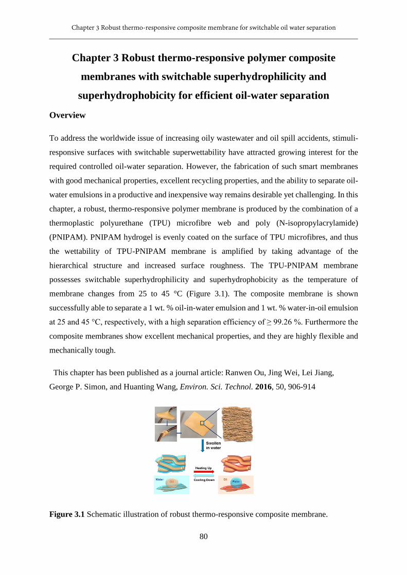
Chapter 3 Robust thermo-responsive composite membrane for switchable oil water separation
80
Chapter 3 Robust thermo-responsive polymer composite
membranes with switchable superhydrophilicity and
superhydrophobicity for efficient oil-water separation
Overview
To address the worldwide issue of increasing oily wastewater and oil spill accidents, stimuli-
responsive surfaces with switchable superwettability have attracted growing interest for the
required controlled oil-water separation. However, the fabrication of such smart membranes
with good mechanical properties, excellent recycling properties, and the ability to separate oil-
water emulsions in a productive and inexpensive way remains desirable yet challenging. In this
chapter, a robust, thermo-responsive polymer membrane is produced by the combination of a
thermoplastic polyurethane (TPU) microfibre web and poly (N-isopropylacrylamide)
(PNIPAM). PNIPAM hydrogel is evenly coated on the surface of TPU microfibres, and thus
the wettability of TPU-PNIPAM membrane is amplified by taking advantage of the
hierarchical structure and increased surface roughness. The TPU-PNIPAM membrane
possesses switchable superhydrophilicity and superhydrophobicity as the temperature of
membrane changes from 25 to 45 °C (Figure 3.1). The composite membrane is shown
successfully able to separate a 1 wt. % oil-in-water emulsion and 1 wt. % water-in-oil emulsion
at 25 and 45 °C, respectively, with a high separation efficiency of ≥ 99.26 %. Furthermore the
composite membranes show excellent mechanical properties, and they are highly flexible and
mechanically tough.
This chapter has been published as a journal article: Ranwen Ou, Jing Wei, Lei Jiang,
George P. Simon, and Huanting Wang, Environ. Sci. Technol. 2016, 50, 906-914
Figure 3.1 Schematic illustration of robust thermo-responsive composite membrane.
Chapter 3 Robust thermo-responsive composite membrane for switchable oil water separation
81
3.1 Introduction
The ability to separate oil-water mixtures has recently attracted worldwide attention because
of increasing amounts of oil-polluted wastewater, frequent oil spill accidents and the ongoing
development of petroleum industry.[1, 2] In general, immiscible oil-water mixtures are
separated using conventional separation techniques, such as gravity separation and oil-
absorbing materials. In the case of the separation of oil-water emulsions, the conventional
separation processes (air flotation, coagulation and flocculation) are costly, energy intensive
and are not effective.[3-5] Pressure-driven membranes, especially ultrafiltration (UF)
membranes, have been successfully used for the separation of oil-water emulsions. However,
the size-sieving mechanism of UF membrane limits the practicality of this process, due to the
resultant high energy consumption, low flux and rapid decrease in permeability with usage.[6-
10] Recently, a series of superwetting membranes have been produced for efficient oil-water
separation, including polymer-coated copper meshes, hydrogel-coated copper meshes, surface-
modified copper meshes and polymer networks,[11-16] all taking advantage of surface
chemistry and roughness.[17] It has been shown that a superhydrophilic / superoleophobic
membrane is suitable for separating oil-in-water emulsions, while a superhydrophobic /
superoleophilic membrane separates water-in-oil emulsions.[16, 18] The oil-water separation
process with a superwetting membrane has been proven to be energy-efficient and cost-
effective, as the membrane separates the oil-water mixture or oil-water emulsion according to
the different interfacial effects of oil and water on the superwetting surface. For example, the
superwetting membrane prepared by Kota et al. allowed for the removal of dispersed-phase
droplets that were considerably smaller than the membrane pore size.[12] It is important to be
able to prepare a responsive membrane with switchable superwettability, not only for
controllable oil-water separation, but also for fabricating intelligent materials. Stimuli-
responsive surfaces have been used to prepare smart membrane for some years, but to date
there are only a few works that have been reported on responsive membranes with switchable
underwater superoleophilicity and superoleophobicity, and fewer membranes with switchable
superhydrophilicity and superhydrophobicity, for oil-water separation. The membranes
reported to date with such switchable underwater superoleophilicity and superoleophobicity
are pH-sensitive.[19-23] For those with switchable superhydrophilicity and
superhydrophobicity, they are photo-induced or pH-responsive. Recently, an aligned ZnO
nanorod arrays-coated mesh film was fabricated by Tian et al., which was shown able to be
switchable between superhydrophilicity and superhydrophobicity, occurring by photo-
Chapter 3 Robust thermo-responsive composite membrane for switchable oil water separation
82
stimulation.[24] The other membranes with switchable superhydrophilicity and
superhydrophobicity for oil-water separation are pH-responsive and can be controlled using
solutions with different pH values. [25, 26] Some responsive membranes exhibit stimuli-
responsive ability, but they are not capable of switching between superwettabilities. For
example, a PDMAEMA hydrogel-coated copper mesh has been reported which was both
thermo- and pH-responsive; however, it is solely superoleophobic under water without
switchable superwettability.[27] A PVCL-co-PSF copolymer membrane shows thermo-
responsive, but it is hydrophilic with a contact angle of 49.5 °C at room temperature.[28] Table
3.1 shows some attractive superwetting membranes published in recent years. For example,
single-walled carbon nanotube network films and ammonia-modified PVDF membrane were
found to be able to separate 99 % oil-water emulsion, and a PAA-g-PVDF membrane was able
to efficiently separate a 1 % oil-water emulsion;[2, 16] what’s more, a superamphiphilic PVDF
membrane could separate oil-in-water and water-in-oil emulsions.[29] However, the
responsive membranes with switchable superwettability were applied to separate ≥ 10 % oil-
water mixtures and not emulsions.
Apart from oil-water separation properties, the mechanical properties and durability of
membranes are other key factors important for practical application.[2] For instance, polymeric
UF membranes are mainly prepared via phase inversion; however, the porous structure formed
in the phase inversion process greatly weakens the mechanical properties of the membranes,
and thus restricts their applicability. To meet the mechanical requirements for practical
ultrafiltration, support materials (glass, metal, polymer, non-woven fabrics) have been applied
to improve their mechanical property, although it may decrease the permeation flux.[8, 10, 30, 31]
Here, for the first time, a robust, thermo-responsive poly (N-isopropylacrylamide) (PNIPAM)
hydrogel-coated thermoplastic polyurethane (TPU) microfibre membrane is fabricated for
efficient oil-water emulsion separation. The membrane is superhydrophilic at room
temperature (25 °C) and becomes superhydrophobic at a temperature above the lower critical
solution temperature of PNIPAM (LCST, 32°C). TPU was selected for its high elongation,
tensile strength, toughness, wear resistance and good flexibility over a wide temperature range.
PNIPAM is a thermally responsive polymer that switches between hydrophilicity and
hydrophobicity at temperatures lower and higher than its LCST. The force-spinning method
was used to produce a non-woven TPU microfibre mesh or web, and is a rapid and productive
technique to produce a micro- or nanoscale fibre mats in less than a minute. It works by
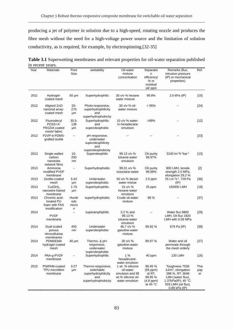
Chapter 3 Robust thermo-responsive composite membrane for switchable oil water separation
83
producing a jet of polymer in solution due to a high-speed, rotating nozzle and produces the
fibre mesh without the need for a high-voltage power source and the limitation of solution
conductivity, as is required, for example, by electrospinning.[32-35]
Table 3.1 Superwetting membranes and relevant properties for oil-water separation published in recent years.
Year Materials Pore Size
wettability Oil-water mixture
concentration
Separation
efficiency/ % or
residual oil/ ppm
Remarks (flux, intrusion pressure (IP) or mechanical
properties)
Ref.
2011
Hydrogel-
coated mesh
50 µm
Superhydrophilic
30 v/v % hexane water mixture
99.8%
2.0 kPa (IP)
[15]
2012 Aligned ZnO nanorod array-coated mesh
25-270 µm
Photo-responsive, superhydrophilicity
and superhydrophobicity
30 v/v % oil-water mixture
> 95% -- [24]
2012 Fluorodecyl POSS+X-
PEGDA coated mesh/ fabric
30.5-138 µm
Superhydrophilic and
superoleophobic
10 v/v % water-in-hexadecane
emulsion
>99% -- [12]
2012 P2VP-b-PDMS-grafted textile
-- pH responsive, underwater
superoleophilicity and
superoleophobicity
-- -- -- [23]
2013 Single-walled carbon
nanotube network films
10-200 nm
Superoleophilic 99.13 v/v % toluene-water
emulsion
Oil purity 99.97%
3100 lm-2h-1bar-1 [13]
2013 Ammonia modified PVDF
membrane
-- Superhydrophobic 99.01 v/v % isooctane-water
Oil purity 99.98%
900 LMH, tensile strength 2.0 MPa, elongation 29.2 %
[2]
2013 Zeolite-coated mesh
5-42 µm
Underwater superoleophobic
50 v/v % diesel-water mixtue
2.5 ppm 25 Lm-2s-1, 729 Pa (IP)
[36]
2013 Cu(OH)2 nanowire-haired
membrane
1-75 µm
Superhydrophilic 10 v/v % hexane-water
emulsion
25 ppm 150000 LMH [18]
2013 Chromic acid-treated PU
foam with FAS modification
Hundreds
micron
superhydrophobic Crude oil-water mixture
98 % -- [37]
2014 PVDF
membrane
-- superamphiphilic 3.2 % and 99.13 %
toluene-water emulsion
-- Water flux 9860 LMH, Oil flux 1820 LMH with 0.09 MPa
[29]
2014 Dual-scaled porous
nitrocellulose membranes
450 nm
Underwater superoleophobic
46.7 v/v % gasoline-water
mixture
99.92 % 679 Pa (IP) [38]
2014 PDMAEMA hydrogel coated
mesh
40 µm Thermo- & pH-responsive, underwater
superoleophobic
30 v/v % gasoline-water
mixture
99.97 % Water and oil permeate through the mesh orderly
[27]
2014 PAA-g-PVDF membrane
-- Superhydrophilic 1 % hexadecane-
water emulsion
40 ppm 130 LMH [16]
2015 PNIPAM-coated TPU microfibre
membrane
3-27 µm
Thermo-responsive, switchable
superhydrophilicity and
superhydrophobicity
1 wt. % silicone oil-water
emulsion and 99 wt.% silicone oil-water emulsion
99.45 % (55 ppm)
at RT, 99.95 %
(4.8 ppm) at 45 °C
Toughness 7536 kJ/m3, elongation 288 %. RT: 3646 LMH (water flux),
1.37kPa(IP); 45 °C: 503 LMH (oil flux),
0.89 kPa (IP)
This paper
Chapter 3 Robust thermo-responsive composite membrane for switchable oil water separation
84
The TPU-PNIPAM composite membrane has excellent mechanical strength, elasticity and
switchable superhydrophilicity and superhydrophobicity, and shows a high efficiency in
separating SDS-stabilized oil-in-water and water-in-oil micro-emulsions, but not mixtures, at
room temperature and at an elevated temperature, respectively.
3.2 Experimental
3.2.1 Materials
The following chemicals were used as supplied: thermoplastic polyurethane (TPU,
TETON*206) particles were kindly provided by Urethane Compounds Pty. Ltd.
Tetrahydrofuran (THF) was purchased from Merck (Kenilworth, NJ, USA). N-isopropyl
acrylamide (NIPAM), N, N-methylene bis (acrylamide) (MBA), and ammonium persulfate
(APS) were purchased from Sigma-Aldrich (St Louis, MO, USA). Distilled deionized (DDI)
water was used in all experiments.
3.2.2 Experimental procedures
Fabrication of TPU-PNIPAM membrane: Thermoplastic polyurethane particles (12 g) were
dissolved in tetrahydrofuran (THF, 88 g) under stirring to obtain a 12 wt. % polymer solution.
N-isopropylacrylamide (NIPAM, 2g, monomer), N, N’-methylenebisacrylamide (MBA, 0.04
g, crosslinker) and ammonium persulfate (APS, 0.02 g, initiator) were dissolved in DDI water
to form a 16.67 wt. % NIPAM reaction solution. As shown in Figure 3.2, the polymer solution
was spun into TPU microfibre mat by a force spinner (Cyclone L-1000M, FibeRio®
Technology Corporation, USA), with an operating condition of 5000 rpm and 30 seconds. Five
microfibre mats were obtained and stacked up to form a TPU microfibre membrane. The as-
prepared TPU microfibre membrane was then cut into a certain shape before wetting with
NIPAM reaction solution. Free-radical polymerization of the NIPAM monomer solution was
applied to coat the PNIPAM hydrogel on the TPU microfibres’ surface. After 2 hours reaction
at 70 °C, TPU-PNIPAM membranes were obtained. The PNIPAM hydrogel loading of TPU-
PNIPAM membranes was controlled by changing the amount of NIPAM reaction solution
added to the TPU microfibre membranes. The TPU-PNIPAM membranes were washed with
25 °C water and 45 °C water more than 10 times to rinse the excess monomer before use.
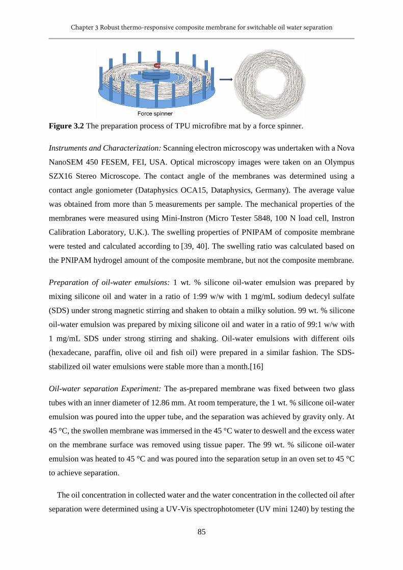
Chapter 3 Robust thermo-responsive composite membrane for switchable oil water separation
85
Figure 3.2 The preparation process of TPU microfibre mat by a force spinner.
Instruments and Characterization: Scanning electron microscopy was undertaken with a Nova
NanoSEM 450 FESEM, FEI, USA. Optical microscopy images were taken on an Olympus
SZX16 Stereo Microscope. The contact angle of the membranes was determined using a
contact angle goniometer (Dataphysics OCA15, Dataphysics, Germany). The average value
was obtained from more than 5 measurements per sample. The mechanical properties of the
membranes were measured using Mini-Instron (Micro Tester 5848, 100 N load cell, Instron
Calibration Laboratory, U.K.). The swelling properties of PNIPAM of composite membrane
were tested and calculated according to [39, 40]. The swelling ratio was calculated based on
the PNIPAM hydrogel amount of the composite membrane, but not the composite membrane.
Preparation of oil-water emulsions: 1 wt. % silicone oil-water emulsion was prepared by
mixing silicone oil and water in a ratio of 1:99 w/w with 1 mg/mL sodium dedecyl sulfate
(SDS) under strong magnetic stirring and shaken to obtain a milky solution. 99 wt. % silicone
oil-water emulsion was prepared by mixing silicone oil and water in a ratio of 99:1 w/w with
1 mg/mL SDS under strong stirring and shaking. Oil-water emulsions with different oils
(hexadecane, paraffin, olive oil and fish oil) were prepared in a similar fashion. The SDS-
stabilized oil water emulsions were stable more than a month.[16]
Oil-water separation Experiment: The as-prepared membrane was fixed between two glass
tubes with an inner diameter of 12.86 mm. At room temperature, the 1 wt. % silicone oil-water
emulsion was poured into the upper tube, and the separation was achieved by gravity only. At
45 °C, the swollen membrane was immersed in the 45 °C water to deswell and the excess water
on the membrane surface was removed using tissue paper. The 99 wt. % silicone oil-water
emulsion was heated to 45 °C and was poured into the separation setup in an oven set to 45 °C
to achieve separation.
The oil concentration in collected water and the water concentration in the collected oil after
separation were determined using a UV-Vis spectrophotometer (UV mini 1240) by testing the
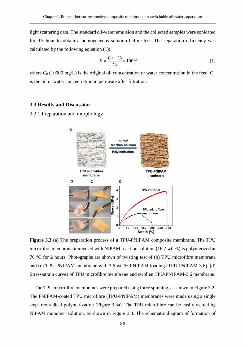
Chapter 3 Robust thermo-responsive composite membrane for switchable oil water separation
86
light scattering data. The standard oil-water emulsion and the collected samples were sonicated
for 0.5 hour to obtain a homogeneous solution before test. The separation efficiency was
calculated by the following equation (1):
%1000
10×
−=
CCCS (1)
where C0 (10000 mg/L) is the original oil concentration or water concentration in the feed. C1
is the oil or water concentration in permeate after filtration.
3.3 Results and Discussion
3.3.1 Preparation and morphology
Figure 3.3 (a) The preparation process of a TPU-PNIPAM composite membrane. The TPU
microfibre membrane immersed with NIPAM reaction solution (16.7 wt. %) is polymerized at
70 °C for 2 hours. Photographs are shown of twisting test of (b) TPU microfibre membrane
and (c) TPU-PNIPAM membrane with 3.6 wt. % PNIPAM loading (TPU-PNIPAM-3.6). (d)
Stress-strain curves of TPU microfibre membrane and swollen TPU-PNIPAM-3.6 membrane.
The TPU microfibre membranes were prepared using force spinning, as shown in Figure 3.2.
The PNIPAM-coated TPU microfibre (TPU-PNIPAM) membranes were made using a single
step free-radical polymerization (Figure 3.3a). The TPU microfibre can be easily wetted by
NIPAM monomer solution, as shown in Figure 3.4. The schematic diagram of formation of
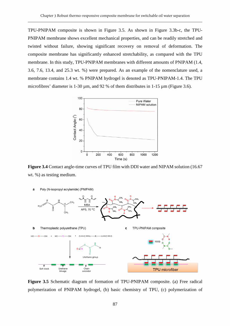
Chapter 3 Robust thermo-responsive composite membrane for switchable oil water separation
87
TPU-PNIPAM composite is shown in Figure 3.5. As shown in Figure 3.3b-c, the TPU-
PNIPAM membrane shows excellent mechanical properties, and can be readily stretched and
twisted without failure, showing significant recovery on removal of deformation. The
composite membrane has significantly enhanced stretchability, as compared with the TPU
membrane. In this study, TPU-PNIPAM membranes with different amounts of PNIPAM (1.4,
3.6, 7.6, 13.4, and 25.3 wt. %) were prepared. As an example of the nomenclature used, a
membrane contains 1.4 wt. % PNIPAM hydrogel is denoted as TPU-PNIPAM-1.4. The TPU
microfibres’ diameter is 1-30 µm, and 92 % of them distributes in 1-15 µm (Figure 3.6).
Figure 3.4 Contact angle-time curves of TPU film with DDI water and NIPAM solution (16.67
wt. %) as testing medium.
Figure 3.5 Schematic diagram of formation of TPU-PNIPAM composite. (a) Free radical
polymerization of PNIPAM hydrogel, (b) basic chemistry of TPU, (c) polymerization of
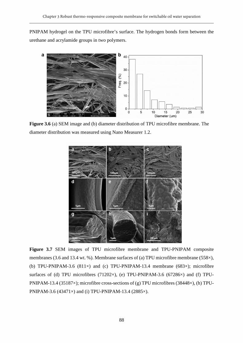
Chapter 3 Robust thermo-responsive composite membrane for switchable oil water separation
88
PNIPAM hydrogel on the TPU microfibre’s surface. The hydrogen bonds form between the
urethane and acrylamide groups in two polymers.
Figure 3.6 (a) SEM image and (b) diameter distribution of TPU microfibre membrane. The
diameter distribution was measured using Nano Measurer 1.2.
Figure 3.7 SEM images of TPU microfibre membrane and TPU-PNIPAM composite
membranes (3.6 and 13.4 wt. %). Membrane surfaces of (a) TPU microfibre membrane (558×),
(b) TPU-PNIPAM-3.6 (811×) and (c) TPU-PNIPAM-13.4 membrane (683×); microfibre
surfaces of (d) TPU microfibres (71202×), (e) TPU-PNIPAM-3.6 (67286×) and (f) TPU-
PNIPAM-13.4 (35187×); microfibre cross-sections of (g) TPU microfibres (38448×), (h) TPU-
PNIPAM-3.6 (43471×) and (i) TPU-PNIPAM-13.4 (2885×).
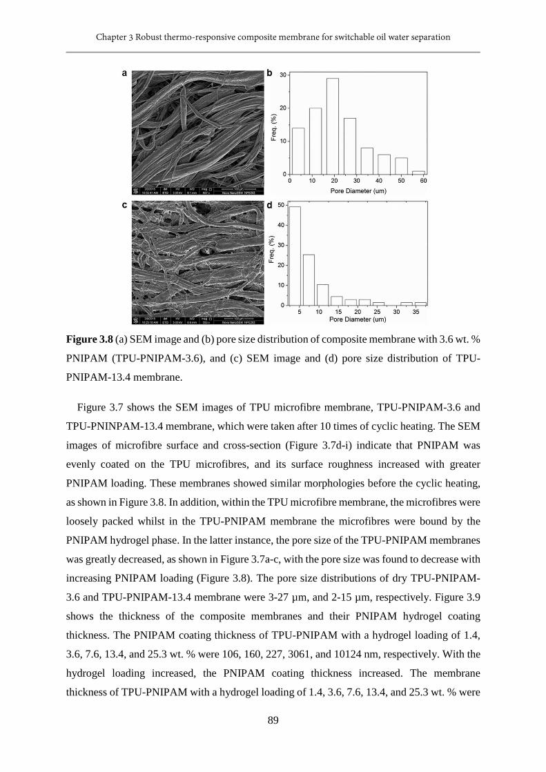
Chapter 3 Robust thermo-responsive composite membrane for switchable oil water separation
89
Figure 3.8 (a) SEM image and (b) pore size distribution of composite membrane with 3.6 wt. %
PNIPAM (TPU-PNIPAM-3.6), and (c) SEM image and (d) pore size distribution of TPU-
PNIPAM-13.4 membrane.
Figure 3.7 shows the SEM images of TPU microfibre membrane, TPU-PNIPAM-3.6 and
TPU-PNINPAM-13.4 membrane, which were taken after 10 times of cyclic heating. The SEM
images of microfibre surface and cross-section (Figure 3.7d-i) indicate that PNIPAM was
evenly coated on the TPU microfibres, and its surface roughness increased with greater
PNIPAM loading. These membranes showed similar morphologies before the cyclic heating,
as shown in Figure 3.8. In addition, within the TPU microfibre membrane, the microfibres were
loosely packed whilst in the TPU-PNIPAM membrane the microfibres were bound by the
PNIPAM hydrogel phase. In the latter instance, the pore size of the TPU-PNIPAM membranes
was greatly decreased, as shown in Figure 3.7a-c, with the pore size was found to decrease with
increasing PNIPAM loading (Figure 3.8). The pore size distributions of dry TPU-PNIPAM-
3.6 and TPU-PNIPAM-13.4 membrane were 3-27 µm, and 2-15 µm, respectively. Figure 3.9
shows the thickness of the composite membranes and their PNIPAM hydrogel coating
thickness. The PNIPAM coating thickness of TPU-PNIPAM with a hydrogel loading of 1.4,
3.6, 7.6, 13.4, and 25.3 wt. % were 106, 160, 227, 3061, and 10124 nm, respectively. With the
hydrogel loading increased, the PNIPAM coating thickness increased. The membrane
thickness of TPU-PNIPAM with a hydrogel loading of 1.4, 3.6, 7.6, 13.4, and 25.3 wt. % were
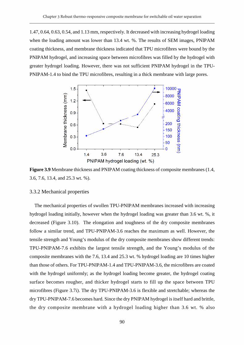
Chapter 3 Robust thermo-responsive composite membrane for switchable oil water separation
90
1.47, 0.64, 0.63, 0.54, and 1.13 mm, respectively. It decreased with increasing hydrogel loading
when the loading amount was lower than 13.4 wt. %. The results of SEM images, PNIPAM
coating thickness, and membrane thickness indicated that TPU microfibres were bound by the
PNIPAM hydrogel, and increasing space between microfibres was filled by the hydrogel with
greater hydrogel loading. However, there was not sufficient PNIPAM hydrogel in the TPU-
PNIPAM-1.4 to bind the TPU microfibres, resulting in a thick membrane with large pores.
Figure 3.9 Membrane thickness and PNIPAM coating thickness of composite membranes (1.4,
3.6, 7.6, 13.4, and 25.3 wt. %).
3.3.2 Mechanical properties
The mechanical properties of swollen TPU-PNIPAM membranes increased with increasing
hydrogel loading initially, however when the hydrogel loading was greater than 3.6 wt. %, it
decreased (Figure 3.10). The elongation and toughness of the dry composite membranes
follow a similar trend, and TPU-PNIPAM-3.6 reaches the maximum as well. However, the
tensile strength and Young’s modulus of the dry composite membranes show different trends:
TPU-PNIPAM-7.6 exhibits the largest tensile strength, and the Young’s modulus of the
composite membranes with the 7.6, 13.4 and 25.3 wt. % hydrogel loading are 10 times higher
than those of others. For TPU-PNIPAM-1.4 and TPU-PNIPAM-3.6, the microfibres are coated
with the hydrogel uniformly; as the hydrogel loading become greater, the hydrogel coating
surface becomes rougher, and thicker hydrogel starts to fill up the space between TPU
microfibres (Figure 3.7i). The dry TPU-PNIPAM-3.6 is flexible and stretchable; whereas the
dry TPU-PNIPAM-7.6 becomes hard. Since the dry PNIPAM hydrogel is itself hard and brittle,
the dry composite membrane with a hydrogel loading higher than 3.6 wt. % also
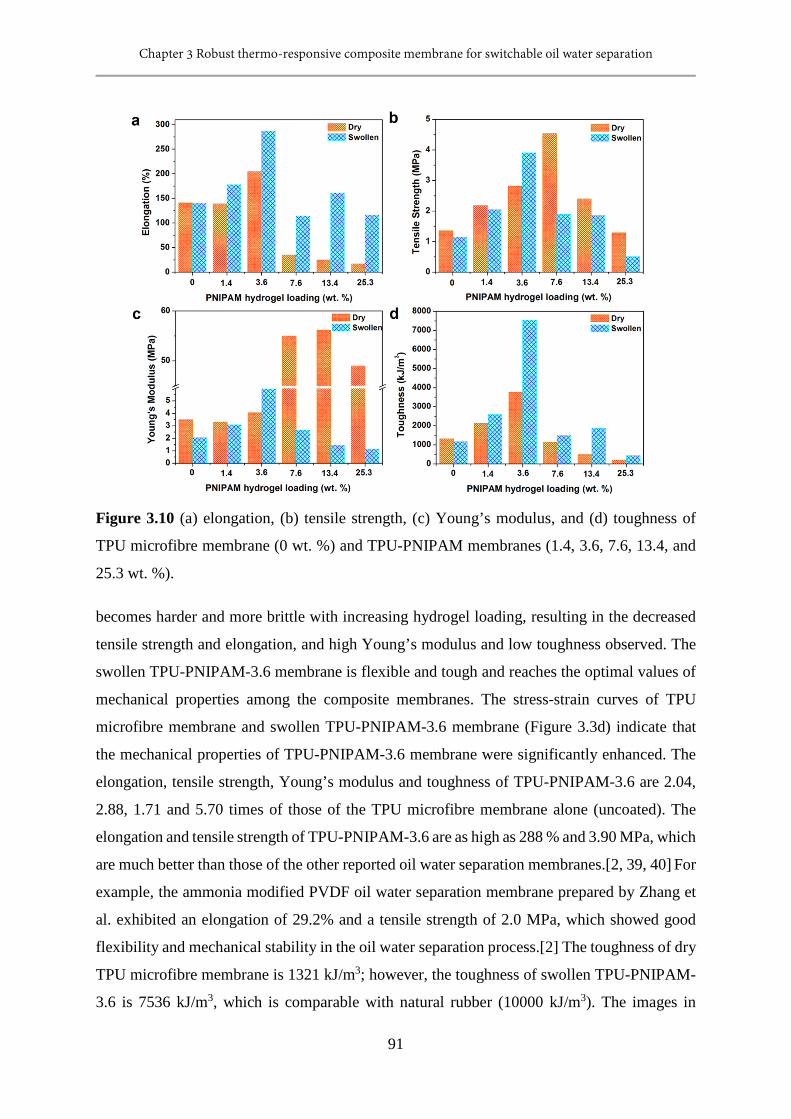
Chapter 3 Robust thermo-responsive composite membrane for switchable oil water separation
91
Figure 3.10 (a) elongation, (b) tensile strength, (c) Young’s modulus, and (d) toughness of
TPU microfibre membrane (0 wt. %) and TPU-PNIPAM membranes (1.4, 3.6, 7.6, 13.4, and
25.3 wt. %).
becomes harder and more brittle with increasing hydrogel loading, resulting in the decreased
tensile strength and elongation, and high Young’s modulus and low toughness observed. The
swollen TPU-PNIPAM-3.6 membrane is flexible and tough and reaches the optimal values of
mechanical properties among the composite membranes. The stress-strain curves of TPU
microfibre membrane and swollen TPU-PNIPAM-3.6 membrane (Figure 3.3d) indicate that
the mechanical properties of TPU-PNIPAM-3.6 membrane were significantly enhanced. The
elongation, tensile strength, Young’s modulus and toughness of TPU-PNIPAM-3.6 are 2.04,
2.88, 1.71 and 5.70 times of those of the TPU microfibre membrane alone (uncoated). The
elongation and tensile strength of TPU-PNIPAM-3.6 are as high as 288 % and 3.90 MPa, which
are much better than those of the other reported oil water separation membranes.[2, 39, 40] For
example, the ammonia modified PVDF oil water separation membrane prepared by Zhang et
al. exhibited an elongation of 29.2% and a tensile strength of 2.0 MPa, which showed good
flexibility and mechanical stability in the oil water separation process.[2] The toughness of dry
TPU microfibre membrane is 1321 kJ/m3; however, the toughness of swollen TPU-PNIPAM-
3.6 is 7536 kJ/m3, which is comparable with natural rubber (10000 kJ/m3). The images in
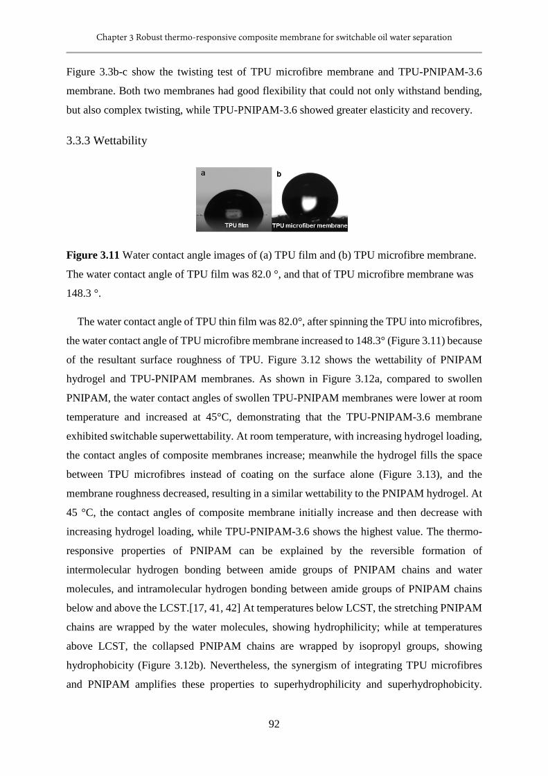
Chapter 3 Robust thermo-responsive composite membrane for switchable oil water separation
92
Figure 3.3b-c show the twisting test of TPU microfibre membrane and TPU-PNIPAM-3.6
membrane. Both two membranes had good flexibility that could not only withstand bending,
but also complex twisting, while TPU-PNIPAM-3.6 showed greater elasticity and recovery.
3.3.3 Wettability
Figure 3.11 Water contact angle images of (a) TPU film and (b) TPU microfibre membrane.
The water contact angle of TPU film was 82.0 °, and that of TPU microfibre membrane was
148.3 °.
The water contact angle of TPU thin film was 82.0°, after spinning the TPU into microfibres,
the water contact angle of TPU microfibre membrane increased to 148.3° (Figure 3.11) because
of the resultant surface roughness of TPU. Figure 3.12 shows the wettability of PNIPAM
hydrogel and TPU-PNIPAM membranes. As shown in Figure 3.12a, compared to swollen
PNIPAM, the water contact angles of swollen TPU-PNIPAM membranes were lower at room
temperature and increased at 45°C, demonstrating that the TPU-PNIPAM-3.6 membrane
exhibited switchable superwettability. At room temperature, with increasing hydrogel loading,
the contact angles of composite membranes increase; meanwhile the hydrogel fills the space
between TPU microfibres instead of coating on the surface alone (Figure 3.13), and the
membrane roughness decreased, resulting in a similar wettability to the PNIPAM hydrogel. At
45 °C, the contact angles of composite membrane initially increase and then decrease with
increasing hydrogel loading, while TPU-PNIPAM-3.6 shows the highest value. The thermo-
responsive properties of PNIPAM can be explained by the reversible formation of
intermolecular hydrogen bonding between amide groups of PNIPAM chains and water
molecules, and intramolecular hydrogen bonding between amide groups of PNIPAM chains
below and above the LCST.[17, 41, 42] At temperatures below LCST, the stretching PNIPAM
chains are wrapped by the water molecules, showing hydrophilicity; while at temperatures
above LCST, the collapsed PNIPAM chains are wrapped by isopropyl groups, showing
hydrophobicity (Figure 3.12b). Nevertheless, the synergism of integrating TPU microfibres
and PNIPAM amplifies these properties to superhydrophilicity and superhydrophobicity.
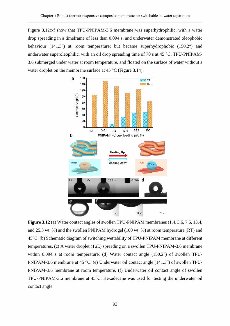
Chapter 3 Robust thermo-responsive composite membrane for switchable oil water separation
93
Figure 3.12c-f show that TPU-PNIPAM-3.6 membrane was superhydrophilic, with a water
drop spreading in a timeframe of less than 0.094 s, and underwater demonstrated oleophobic
behaviour (141.3°) at room temperature; but became superhydrophobic (150.2°) and
underwater superoleophilic, with an oil drop spreading time of 70 s at 45 °C. TPU-PNIPAM-
3.6 submerged under water at room temperature, and floated on the surface of water without a
water droplet on the membrane surface at 45 °C (Figure 3.14).
Figure 3.12 (a) Water contact angles of swollen TPU-PNIPAM membranes (1.4, 3.6, 7.6, 13.4,
and 25.3 wt. %) and the swollen PNIPAM hydrogel (100 wt. %) at room temperature (RT) and
45°C. (b) Schematic diagram of switching wettability of TPU-PNIPAM membrane at different
temperatures. (c) A water droplet (1µL) spreading on a swollen TPU-PNIPAM-3.6 membrane
within 0.094 s at room temperature. (d) Water contact angle (150.2°) of swollen TPU-
PNIPAM-3.6 membrane at 45 °C. (e) Underwater oil contact angle (141.3°) of swollen TPU-
PNIPAM-3.6 membrane at room temperature. (f) Underwater oil contact angle of swollen
TPU-PNIPAM-3.6 membrane at 45°C. Hexadecane was used for testing the underwater oil
contact angle.
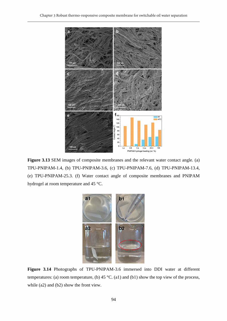
Chapter 3 Robust thermo-responsive composite membrane for switchable oil water separation
94
Figure 3.13 SEM images of composite membranes and the relevant water contact angle. (a)
TPU-PNIPAM-1.4, (b) TPU-PNIPAM-3.6, (c) TPU-PNIPAM-7.6, (d) TPU-PNIPAM-13.4,
(e) TPU-PNIPAM-25.3. (f) Water contact angle of composite membranes and PNIPAM
hydrogel at room temperature and 45 °C.
Figure 3.14 Photographs of TPU-PNIPAM-3.6 immersed into DDI water at different
temperatures: (a) room temperature, (b) 45 °C. (a1) and (b1) show the top view of the process,
while (a2) and (b2) show the front view.

Chapter 3 Robust thermo-responsive composite membrane for switchable oil water separation
95
3.3.4 Swelling behaviour
Figure 3.15 Swelling properties of the PNIPAM of TPU-PNIPAM-3.6 membrane. (a) Swelling
curve of dry TPU-PNIPAM-3.6 membrane. (b) Swelling ratio of TPU-PNIPAM-3.6 membrane
at different temperatures. (c) Deswelling curve of TPU-PNIPAM-3.6 membrane tested at 45 °C
DDI water. (d) Reswelling curve of TPU-PNIPAM-3.6 membrane tested at 25°C DDI water.
Apart from the wettability, the degree of swelling also plays an important role in the potential
use of the hydrogel. It has been recognized that PNIPAM hydrogels would possess low
reswelling and deswelling rates at temperatures below or over its LCST, which is responsible
for the formation of a dense, hydrophobic layer at the surface of the hydrogels due to the
occurrence of volume-phase transition (VPT) that retards the collective diffusion of water
molecules in the swelled and/or deswelled hydrogels.[39, 40, 43, 44] Figure 3.15 shows the
swelling properties of the PNIPAM phase of the TPU-PNIPAM-3.6 membrane. It took 400
minutes for dry TPU-PNIPAM-3.6 membrane to achieve a swelling equilibrium in DDI water
(Figure 3.15a). Even though the swelling ratio of the PNIPAM was 5.36 g/g, the appearance of
the membrane changed little because of the small amount of hydrogel loading. The LCST of
TPU-PNIPAM-3.6 membrane is the same as PNIPAM hydrogel, some 32-33 °C (Figure 3.15b).
Importantly, the deswelling and reswelling equilibrium of TPU-PNIPAM-3.6 membrane could
be achieved in less than 3 minutes by immersing it into 45 °C and 25 °C DDI water, respectively,
as shown in Figure 3.15c-d. The rapid deswelling and reswelling properties could be a result
of the morphology of hydrogel nanoparticles on the microfibres surface and the consequent
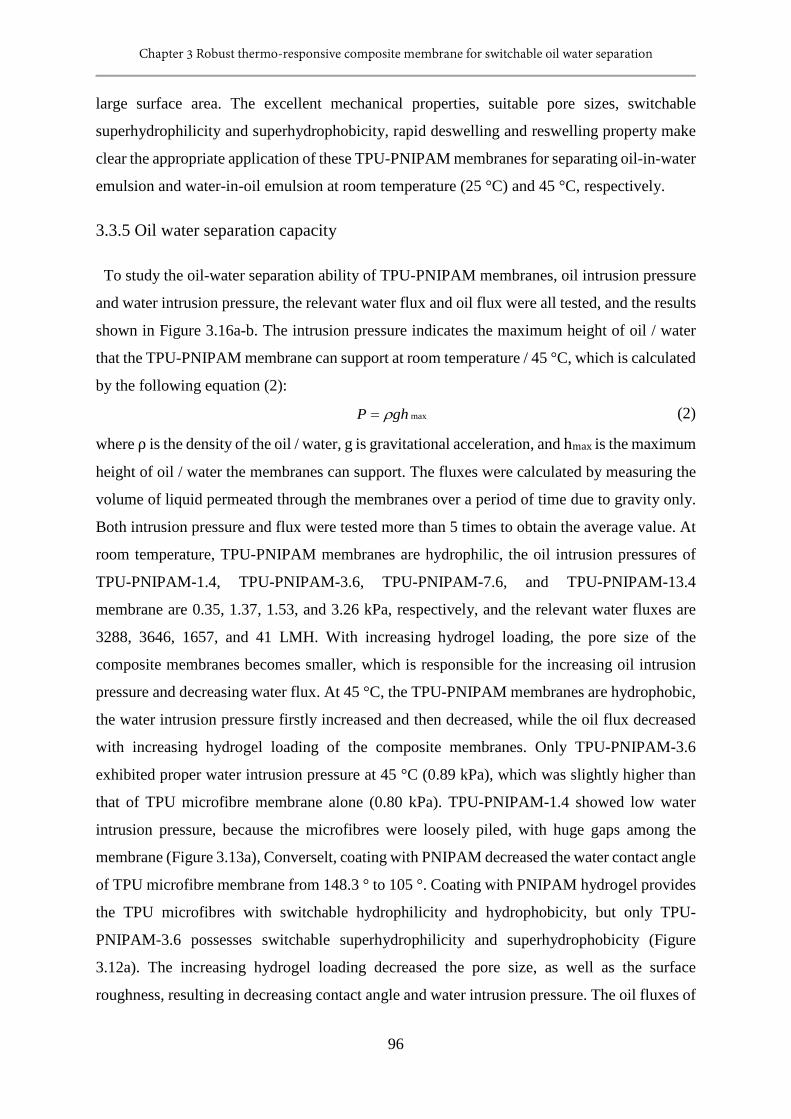
Chapter 3 Robust thermo-responsive composite membrane for switchable oil water separation
96
large surface area. The excellent mechanical properties, suitable pore sizes, switchable
superhydrophilicity and superhydrophobicity, rapid deswelling and reswelling property make
clear the appropriate application of these TPU-PNIPAM membranes for separating oil-in-water
emulsion and water-in-oil emulsion at room temperature (25 °C) and 45 °C, respectively.
3.3.5 Oil water separation capacity
To study the oil-water separation ability of TPU-PNIPAM membranes, oil intrusion pressure
and water intrusion pressure, the relevant water flux and oil flux were all tested, and the results
shown in Figure 3.16a-b. The intrusion pressure indicates the maximum height of oil / water
that the TPU-PNIPAM membrane can support at room temperature / 45 °C, which is calculated
by the following equation (2):
maxghP ρ= (2)
where ρ is the density of the oil / water, g is gravitational acceleration, and hmax is the maximum
height of oil / water the membranes can support. The fluxes were calculated by measuring the
volume of liquid permeated through the membranes over a period of time due to gravity only.
Both intrusion pressure and flux were tested more than 5 times to obtain the average value. At
room temperature, TPU-PNIPAM membranes are hydrophilic, the oil intrusion pressures of
TPU-PNIPAM-1.4, TPU-PNIPAM-3.6, TPU-PNIPAM-7.6, and TPU-PNIPAM-13.4
membrane are 0.35, 1.37, 1.53, and 3.26 kPa, respectively, and the relevant water fluxes are
3288, 3646, 1657, and 41 LMH. With increasing hydrogel loading, the pore size of the
composite membranes becomes smaller, which is responsible for the increasing oil intrusion
pressure and decreasing water flux. At 45 °C, the TPU-PNIPAM membranes are hydrophobic,
the water intrusion pressure firstly increased and then decreased, while the oil flux decreased
with increasing hydrogel loading of the composite membranes. Only TPU-PNIPAM-3.6
exhibited proper water intrusion pressure at 45 °C (0.89 kPa), which was slightly higher than
that of TPU microfibre membrane alone (0.80 kPa). TPU-PNIPAM-1.4 showed low water
intrusion pressure, because the microfibres were loosely piled, with huge gaps among the
membrane (Figure 3.13a), Converselt, coating with PNIPAM decreased the water contact angle
of TPU microfibre membrane from 148.3 ° to 105 °. Coating with PNIPAM hydrogel provides
the TPU microfibres with switchable hydrophilicity and hydrophobicity, but only TPU-
PNIPAM-3.6 possesses switchable superhydrophilicity and superhydrophobicity (Figure
3.12a). The increasing hydrogel loading decreased the pore size, as well as the surface
roughness, resulting in decreasing contact angle and water intrusion pressure. The oil fluxes of
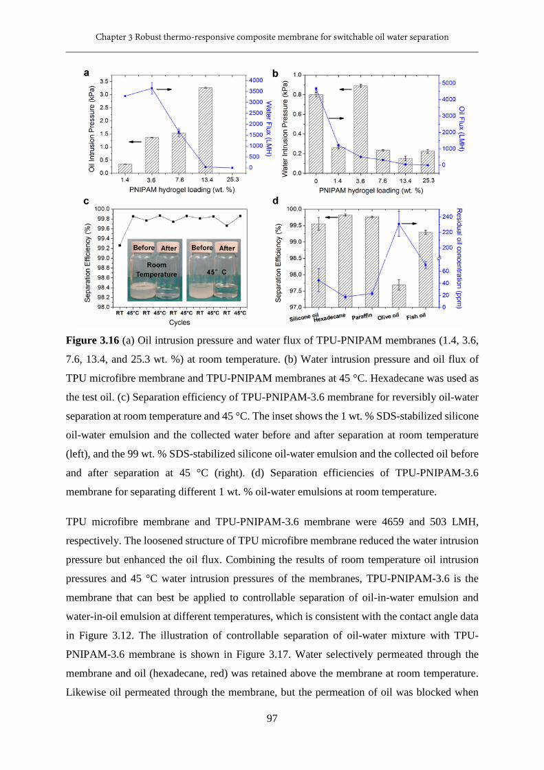
Chapter 3 Robust thermo-responsive composite membrane for switchable oil water separation
97
Figure 3.16 (a) Oil intrusion pressure and water flux of TPU-PNIPAM membranes (1.4, 3.6,
7.6, 13.4, and 25.3 wt. %) at room temperature. (b) Water intrusion pressure and oil flux of
TPU microfibre membrane and TPU-PNIPAM membranes at 45 °C. Hexadecane was used as
the test oil. (c) Separation efficiency of TPU-PNIPAM-3.6 membrane for reversibly oil-water
separation at room temperature and 45 °C. The inset shows the 1 wt. % SDS-stabilized silicone
oil-water emulsion and the collected water before and after separation at room temperature
(left), and the 99 wt. % SDS-stabilized silicone oil-water emulsion and the collected oil before
and after separation at 45 °C (right). (d) Separation efficiencies of TPU-PNIPAM-3.6
membrane for separating different 1 wt. % oil-water emulsions at room temperature.
TPU microfibre membrane and TPU-PNIPAM-3.6 membrane were 4659 and 503 LMH,
respectively. The loosened structure of TPU microfibre membrane reduced the water intrusion
pressure but enhanced the oil flux. Combining the results of room temperature oil intrusion
pressures and 45 °C water intrusion pressures of the membranes, TPU-PNIPAM-3.6 is the
membrane that can best be applied to controllable separation of oil-in-water emulsion and
water-in-oil emulsion at different temperatures, which is consistent with the contact angle data
in Figure 3.12. The illustration of controllable separation of oil-water mixture with TPU-
PNIPAM-3.6 membrane is shown in Figure 3.17. Water selectively permeated through the
membrane and oil (hexadecane, red) was retained above the membrane at room temperature.
Likewise oil permeated through the membrane, but the permeation of oil was blocked when
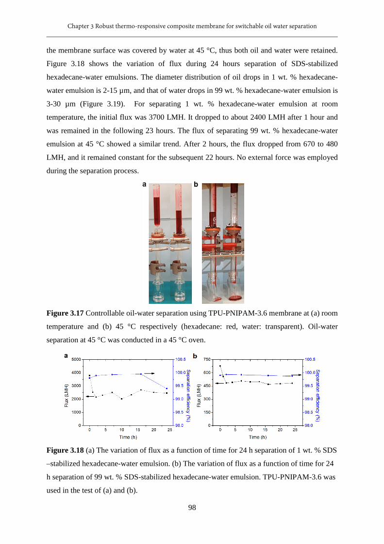
Chapter 3 Robust thermo-responsive composite membrane for switchable oil water separation
98
the membrane surface was covered by water at 45 °C, thus both oil and water were retained.
Figure 3.18 shows the variation of flux during 24 hours separation of SDS-stabilized
hexadecane-water emulsions. The diameter distribution of oil drops in 1 wt. % hexadecane-
water emulsion is 2-15 µm, and that of water drops in 99 wt. % hexadecane-water emulsion is
3-30 µm (Figure 3.19). For separating 1 wt. % hexadecane-water emulsion at room
temperature, the initial flux was 3700 LMH. It dropped to about 2400 LMH after 1 hour and
was remained in the following 23 hours. The flux of separating 99 wt. % hexadecane-water
emulsion at 45 °C showed a similar trend. After 2 hours, the flux dropped from 670 to 480
LMH, and it remained constant for the subsequent 22 hours. No external force was employed
during the separation process.
Figure 3.17 Controllable oil-water separation using TPU-PNIPAM-3.6 membrane at (a) room
temperature and (b) 45 °C respectively (hexadecane: red, water: transparent). Oil-water
separation at 45 °C was conducted in a 45 °C oven.
Figure 3.18 (a) The variation of flux as a function of time for 24 h separation of 1 wt. % SDS
–stabilized hexadecane-water emulsion. (b) The variation of flux as a function of time for 24
h separation of 99 wt. % SDS-stabilized hexadecane-water emulsion. TPU-PNIPAM-3.6 was
used in the test of (a) and (b).
Chapter 3 Robust thermo-responsive composite membrane for switchable oil water separation
99
Silicone oil, with a density approaching that of water, was used to prepare the emulsion with
water for testing the oil-water emulsion separation capability of TPU-PNIPAM-3.6 membrane.
1 wt. % silicone oil-water emulsion contains 1 wt. % silicone oil, 99 wt. % DDI water and 1
mg/mL sodium dedecyl sulfate (SDS), it is oil-in-water emulsion. Similarly, 99 wt. % silicone
oil-water emulsion contains 99 wt. % silicone oil, 1 wt. % DDI water and 1 mg/mL SDS, and
thus is a water-in-oil emulsion. The silicone oil-water emulsions were much more stable than
the hexadecane-water emulsions. The diameter of silicone oil drops in water is 2-25 µm, and
that of water drops in silicone oil is 5-30 µm (Figure 3.19). The TPU-PNIPAM-3.6 membrane
was able to demonstrate excellent ability to separate oil-water emulsions. At room temperature,
1 wt. % silicone oil-water emulsion was separated, and the separation efficiency was higher
than 99.26 %; at 45 °C, 99 wt. % silicone oil-water emulsion was separated, and the separation
efficiency was 99.85 %. TPU-PNIPAM-3.6 showed switchable superhydrophilicity and
superhydrophobicity, it separated oil-in-water and water-in-oil emulsions at temperatures
below and above LCST respectively. However, the TPU microfibre membrane showed
hydrophobicity, it separated a water-in-oil emulsion only. The TPU microfibre membrane was
applied to separate 99 wt. % silicone oil-water emulsion, and the separation efficiency was
99.78 %. For separating water-in-oil emulsion, even though TPU-PNIPAM-3.6 was swollen in
45 °C water, it showed similar separation efficiency with the dry TPU microfibre membrane.
The separation efficiencies of TPU-PNIPAM-3.6 membrane for reversely separating 1 wt. %
and 99 wt. % silicone oil-water emulsions at room temperature and 45 °C individually are
shown in Figure 3.16c. It was found that the separation efficiencies were stable both at room
temperature and 45 °C, demonstrating that the TPU-PNIPAM-3.6 membrane is stable and
shows excellent separation ability under switching temperatures. The inset of Figure 3.16c
shows photographs of oil-water emulsions and the collected liquids, before and after separation,
which also indicates that the TPU-PNIPAM-3.6 membrane separated emulsions successfully.
Other than for silicone oil-water emulsions, the TPU-PNIPAM-3.6 membrane was able to
separate other oil-water emulsions with high separation efficiency (Figure 3.16d). The optical
microscopy images of emulsions before and after filtration are shown in Figure 3.20 and Figure
3.21.
In conclusion, the TPU microfibre-PNIPAM hydrogel composite membrane (e.g., TPU-
PNIPAM-3.63) exhibit excellent oil-water emulsion separation performance: (1) it separates
water-in-oil and oil-in-water emulsions effectively and efficiently under switching
temperatures, with an separation efficiency of ≥ 99.26 %, while the TPU microfibre membrane
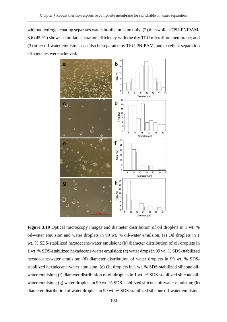
Chapter 3 Robust thermo-responsive composite membrane for switchable oil water separation
100
without hydrogel coating separates water-in-oil emulsion only; (2) the swollen TPU-PNIPAM-
3.6 (45 °C) shows a similar separation efficiency with the dry TPU microfibre membrane; and
(3) other oil-water emulsions can also be separated by TPU-PNIPAM, and excellent separation
efficiencies were achieved.
Figure 3.19 Optical microscopy images and diameter distribution of oil droplets in 1 wt. %
oil-water emulsion and water droplets in 99 wt. % oil-water emulsion. (a) Oil droplets in 1
wt. % SDS-stabilized hexadecane-water emulsion; (b) diameter distribution of oil droplets in
1 wt. % SDS-stabilized hexadecane-water emulsion; (c) water drops in 99 wt. % SDS-stabilized
hexadecane-water emulsion; (d) diameter distribution of water droplets in 99 wt. % SDS-
stabilized hexadecane-water emulsion. (e) Oil droplets in 1 wt. % SDS-stabilized silicone oil-
water emulsion; (f) diameter distribution of oil droplets in 1 wt. % SDS-stabilized silicone oil-
water emulsion; (g) water droplets in 99 wt. % SDS-stabilized silicone oil-water emulsion; (h)
diameter distribution of water droplets in 99 wt. % SDS-stabilized silicone oil-water emulsion.
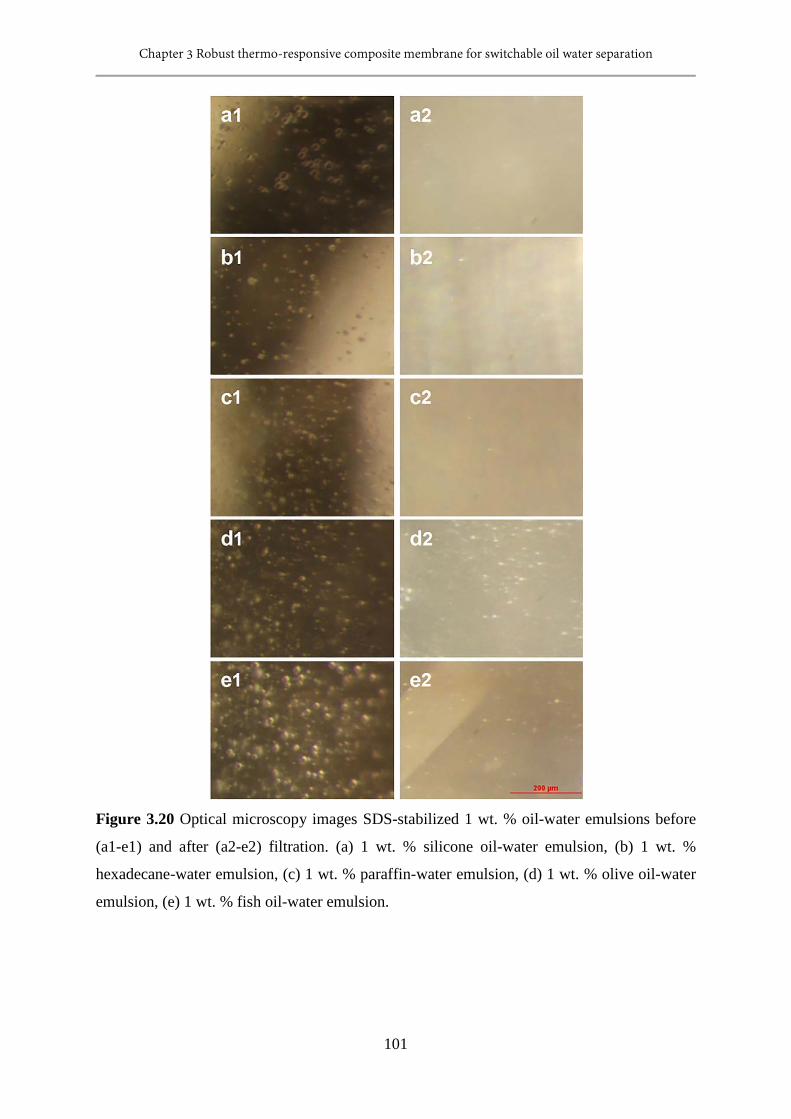
Chapter 3 Robust thermo-responsive composite membrane for switchable oil water separation
101
Figure 3.20 Optical microscopy images SDS-stabilized 1 wt. % oil-water emulsions before
(a1-e1) and after (a2-e2) filtration. (a) 1 wt. % silicone oil-water emulsion, (b) 1 wt. %
hexadecane-water emulsion, (c) 1 wt. % paraffin-water emulsion, (d) 1 wt. % olive oil-water
emulsion, (e) 1 wt. % fish oil-water emulsion.
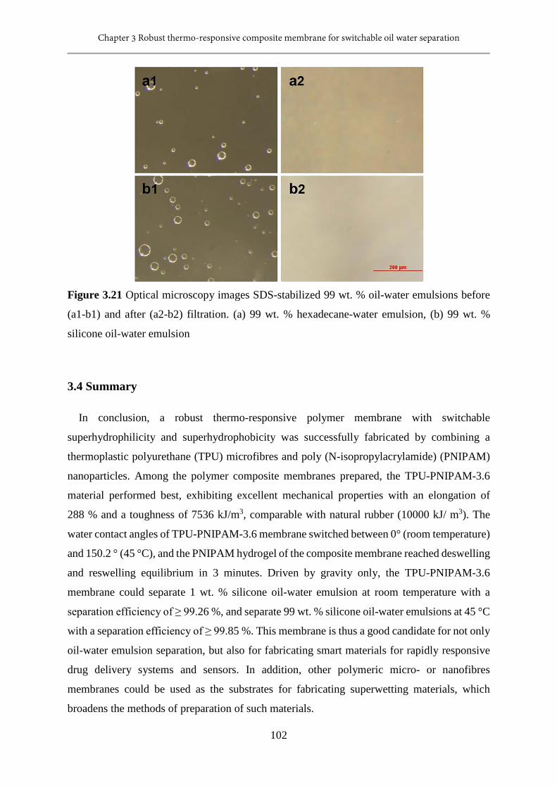
Chapter 3 Robust thermo-responsive composite membrane for switchable oil water separation
102
Figure 3.21 Optical microscopy images SDS-stabilized 99 wt. % oil-water emulsions before
(a1-b1) and after (a2-b2) filtration. (a) 99 wt. % hexadecane-water emulsion, (b) 99 wt. %
silicone oil-water emulsion
3.4 Summary
In conclusion, a robust thermo-responsive polymer membrane with switchable
superhydrophilicity and superhydrophobicity was successfully fabricated by combining a
thermoplastic polyurethane (TPU) microfibres and poly (N-isopropylacrylamide) (PNIPAM)
nanoparticles. Among the polymer composite membranes prepared, the TPU-PNIPAM-3.6
material performed best, exhibiting excellent mechanical properties with an elongation of
288 % and a toughness of 7536 kJ/m3, comparable with natural rubber (10000 kJ/ m3). The
water contact angles of TPU-PNIPAM-3.6 membrane switched between 0° (room temperature)
and 150.2 ° (45 °C), and the PNIPAM hydrogel of the composite membrane reached deswelling
and reswelling equilibrium in 3 minutes. Driven by gravity only, the TPU-PNIPAM-3.6
membrane could separate 1 wt. % silicone oil-water emulsion at room temperature with a
separation efficiency of ≥ 99.26 %, and separate 99 wt. % silicone oil-water emulsions at 45 °C
with a separation efficiency of ≥ 99.85 %. This membrane is thus a good candidate for not only
oil-water emulsion separation, but also for fabricating smart materials for rapidly responsive
drug delivery systems and sensors. In addition, other polymeric micro- or nanofibres
membranes could be used as the substrates for fabricating superwetting materials, which
broadens the methods of preparation of such materials.
Chapter 3 Robust thermo-responsive composite membrane for switchable oil water separation
103
3.5 References
[1] P. Kajitvichyanukul, Y. Hung, L. Wang, Advanced Physicochemical Treatment Processes;
Handbook of Environment Engineering, in, The Humana Press Inc.: Totowa, NJ, 2006.
[2] W. Zhang, Z. Shi, F. Zhang, X. Liu, J. Jin, L. Jiang, Superhydrophobic and Superoleophilic
PVDF Membranes for Effective Separation of Water‐in‐Oil Emulsions with High Flux,
Advanced Materials, 25 (2013) 2071-2076.
[3] B. Chakrabarty, A. Ghoshal, M. Purkait, Ultrafiltration of stable oil-in-water emulsion by
polysulfone membrane, Journal of Membrane Science, 325 (2008) 427-437.
[4] A. El-Kayar, M. Hussein, A. Zatout, A. Hosny, A. Amer, Removal of oil from stable oil-
water emulsion by induced air flotation technique, Separations Technology, 3 (1993) 25-31.
[5] G. Kwon, A. Kota, Y. Li, A. Sohani, J.M. Mabry, A. Tuteja, On‐Demand Separation of
Oil‐Water Mixtures, Advanced Materials, 24 (2012) 3666-3671.
[6] P. Lipp, C. Lee, A. Fane, C. Fell, A fundamental study of the ultrafiltration of oil-water
emulsions, Journal of Membrane Science, 36 (1988) 161-177.
[7] M. Padaki, R.S. Murali, M. Abdullah, N. Misdan, A. Moslehyani, M. Kassim, N. Hilal, A.
Ismail, Membrane technology enhancement in oil–water separation. A review, Desalination,
357 (2015) 197-207.
[8] M.M. Pendergast, E.M. Hoek, A review of water treatment membrane nanotechnologies,
Energy & Environmental Science, 4 (2011) 1946-1971.
[9] D. Rana, T. Matsuura, Surface modifications for antifouling membranes, Chemical reviews,
110 (2010) 2448-2471.
[10] B. Van der Bruggen, C. Vandecasteele, T. Van Gestel, W. Doyen, R. Leysen, A review of
pressure‐driven membrane processes in wastewater treatment and drinking water production,
Environmental progress, 22 (2003) 46-56.
[11] L. Feng, Z. Zhang, Z. Mai, Y. Ma, B. Liu, L. Jiang, D. Zhu, A super‐hydrophobic and
super‐oleophilic coating mesh film for the separation of oil and water, Angewandte Chemie
International Edition, 43 (2004) 2012-2014.
[12] A.K. Kota, G. Kwon, W. Choi, J.M. Mabry, A. Tuteja, Hygro-responsive membranes for
effective oil–water separation, Nature communications, 3 (2012) 1025.
[13] Z. Shi, W. Zhang, F. Zhang, X. Liu, D. Wang, J. Jin, L. Jiang, Ultrafast Separation of
Emulsified Oil/Water Mixtures by Ultrathin Free ‐ Standing Single ‐ Walled Carbon
Nanotube Network Films, Advanced Materials, 25 (2013) 2422-2427.
Chapter 3 Robust thermo-responsive composite membrane for switchable oil water separation
104
[14] C. Wang, T. Yao, J. Wu, C. Ma, Z. Fan, Z. Wang, Y. Cheng, Q. Lin, B. Yang, Facile
approach in fabricating superhydrophobic and superoleophilic surface for water and oil mixture
separation, ACS applied materials & interfaces, 1 (2009) 2613-2617.
[15] Z. Xue, S. Wang, L. Lin, L. Chen, M. Liu, L. Feng, L. Jiang, A Novel Superhydrophilic
and Underwater Superoleophobic Hydrogel ‐ Coated Mesh for Oil/Water Separation,
Advanced Materials, 23 (2011) 4270-4273.
[16] W. Zhang, Y. Zhu, X. Liu, D. Wang, J. Li, L. Jiang, J. Jin, Salt‐Induced Fabrication of
Superhydrophilic and Underwater Superoleophobic PAA ‐ g ‐ PVDF Membranes for
Effective Separation of Oil ‐ in ‐Water Emulsions, Angewandte Chemie International
Edition, 53 (2014) 856-860.
[17] T. Sun, G. Wang, L. Feng, B. Liu, Y. Ma, L. Jiang, D. Zhu, Reversible switching between
superhydrophilicity and superhydrophobicity, Angewandte Chemie International Edition, 43
(2004) 357-360.
[18] F. Zhang, W.B. Zhang, Z. Shi, D. Wang, J. Jin, L. Jiang, Nanowire‐Haired Inorganic
Membranes with Superhydrophilicity and Underwater Ultralow Adhesive Superoleophobicity
for High‐Efficiency Oil/Water Separation, Advanced Materials, 25 (2013) 4192-4198.
[19] Z. Cheng, H. Lai, Y. Du, K. Fu, R. Hou, C. Li, N. Zhang, K. Sun, pH-induced reversible
wetting transition between the underwater superoleophilicity and superoleophobicity, ACS
applied materials & interfaces, 6 (2013) 636-641.
[20] G. Ju, M. Cheng, F. Shi, A pH-responsive smart surface for the continuous separation of
oil/water/oil ternary mixtures, NPG Asia Materials, 6 (2014) e111.
[21] B. Wang, Z. Guo, pH-responsive bidirectional oil–water separation material, Chemical
Communications, 49 (2013) 9416-9418.
[22] B. Wang, Z. Guo, W. Liu, pH-responsive smart fabrics with controllable wettability in
different surroundings, RSC Advances, 4 (2014) 14684-14690.
[23] L. Zhang, Z. Zhang, P. Wang, Smart surfaces with switchable superoleophilicity and
superoleophobicity in aqueous media: toward controllable oil/water separation, NPG Asia
Materials, 4 (2012) e8.
[24] D. Tian, X. Zhang, Y. Tian, Y. Wu, X. Wang, J. Zhai, L. Jiang, Photo-induced water–oil
separation based on switchable superhydrophobicity–superhydrophilicity and underwater
superoleophobicity of the aligned ZnO nanorod array-coated mesh films, Journal of Materials
Chemistry, 22 (2012) 19652-19657.
Chapter 3 Robust thermo-responsive composite membrane for switchable oil water separation
105
[25] Z. Cheng, J. Wang, H. Lai, Y. Du, R. Hou, C. Li, N. Zhang, K. Sun, pH-Controllable On-
Demand Oil/Water Separation on the Switchable Superhydrophobic/Superhydrophilic and
Underwater Low-Adhesive Superoleophobic Copper Mesh Film, Langmuir, 31 (2015) 1393-
1399.
[26] W. Zhang, Y. Cao, N. Liu, Y. Chen, L. Feng, A novel solution-controlled hydrogel coated
mesh for oil/water separation based on monolayer electrostatic self-assembly, RSC Advances,
4 (2014) 51404-51410.
[27] Y. Cao, N. Liu, C. Fu, K. Li, L. Tao, L. Feng, Y. Wei, Thermo and pH dual-responsive
materials for controllable oil/water separation, ACS applied materials & interfaces, 6 (2014)
2026-2030.
[28] M. Sinha, M. Purkait, Preparation of a novel thermo responsive PSF membrane, with cross
linked PVCL-co-PSF copolymer for protein separation and easy cleaning, RSC Advances, 5
(2015) 22609-22619.
[29] M. Tao, L. Xue, F. Liu, L. Jiang, An intelligent superwetting PVDF membrane showing
switchable transport performance for oil/water separation, Advanced Materials, 26 (2014)
2943-2948.
[30] P. Sukitpaneenit, T.-S. Chung, Molecular elucidation of morphology and mechanical
properties of PVDF hollow fiber membranes from aspects of phase inversion, crystallization
and rheology, Journal of Membrane Science, 340 (2009) 192-205.
[31] C. Zhao, J. Xue, F. Ran, S. Sun, Modification of polyethersulfone membranes–a review
of methods, Progress in Materials Science, 58 (2013) 76-150.
[32] M.R. Badrossamay, H.A. McIlwee, J.A. Goss, K.K. Parker, Nanofiber assembly by rotary
jet-spinning, Nano letters, 10 (2010) 2257-2261.
[33] T.B. Mîndru, L. Ignat, I.B. Mîndru, M. Pinteala, Morphological aspects of polymer fiber
mats obtained by air flow rotary-jet spinning, Fibers and Polymers, 14 (2013) 1526-1534.
[34] K. Sarkar, C. Gomez, S. Zambrano, M. Ramirez, E. de Hoyos, H. Vasquez, K. Lozano,
Electrospinning to forcespinning™, Materials Today, 13 (2010) 12-14.
[35] I. Sebe, B. Szabó, Z.K. Nagy, D. Szabo, L. Zsidai, B. Kocsis, R. Zelkó, Polymer structure
and antimicrobial activity of polyvinylpyrrolidone-based iodine nanofibers prepared with high-
speed rotary spinning technique, International journal of pharmaceutics, 458 (2013) 99-103.
[36] Q. Wen, J. Di, L. Jiang, J. Yu, R. Xu, Zeolite-coated mesh film for efficient oil–water
separation, Chemical Science, 4 (2013) 591-595.
Chapter 3 Robust thermo-responsive composite membrane for switchable oil water separation
106
[37] X. Zhang, Z. Li, K. Liu, L. Jiang, Bioinspired Multifunctional Foam with Self‐Cleaning
and Oil/Water Separation, Advanced Functional Materials, 23 (2013) 2881-2886.
[38] X. Gao, L.P. Xu, Z. Xue, L. Feng, J. Peng, Y. Wen, S. Wang, X. Zhang, Dual‐Scaled
Porous Nitrocellulose Membranes with Underwater Superoleophobicity for Highly Efficient
Oil/Water Separation, Advanced Materials, 26 (2014) 1771-1775.
[39] T.a. Asoh, T. Kaneko, M. Matsusaki, M. Akashi, Rapid and Precise Release from Nano‐
Tracted Poly (N‐ isopropylacrylamide) Hydrogels Containing Linear Poly (acrylic acid),
Macromolecular bioscience, 6 (2006) 959-965.
[40] Q. Zheng, S. Zheng, From poly (N‐ isopropylacrylamide)‐block‐poly (ethylene
oxide) ‐ block ‐ poly (N ‐ isopropylacrylamide) triblock copolymer to poly (N ‐
isopropylacrylamide) ‐ block ‐ poly (ethylene oxide) hydrogels: Synthesis and rapid
deswelling and reswelling behavior of hydrogels, Journal of Polymer Science Part A: Polymer
Chemistry, 50 (2012) 1717-1727.
[41] Z. Ahmed, E.A. Gooding, K.V. Pimenov, L. Wang, S.A. Asher, UV resonance Raman
determination of molecular mechanism of poly (N-isopropylacrylamide) volume phase
transition, The Journal of Physical Chemistry B, 113 (2009) 4248-4256.
[42] S.-Y. Lin, K.-S. Chen, R.-C. Liang, Thermal micro ATR/FT-IR spectroscopic system for
quantitative study of the molecular structure of poly (N-isopropylacrylamide) in water,
Polymer, 40 (1999) 2619-2624.
[43] A. Gutowska, Y.H. Bae, J. Feijen, S.W. Kim, Heparin release from thermosensitive
hydrogels, Journal of controlled release, 22 (1992) 95-104.
[44] M.H. Stenzel, T.P. Davis, Star polymer synthesis using trithiocarbonate functional β‐
cyclodextrin cores (reversible addition– fragmentation chain‐ transfer polymerization),
Journal of Polymer Science Part A: Polymer Chemistry, 40 (2002) 4498-4512.
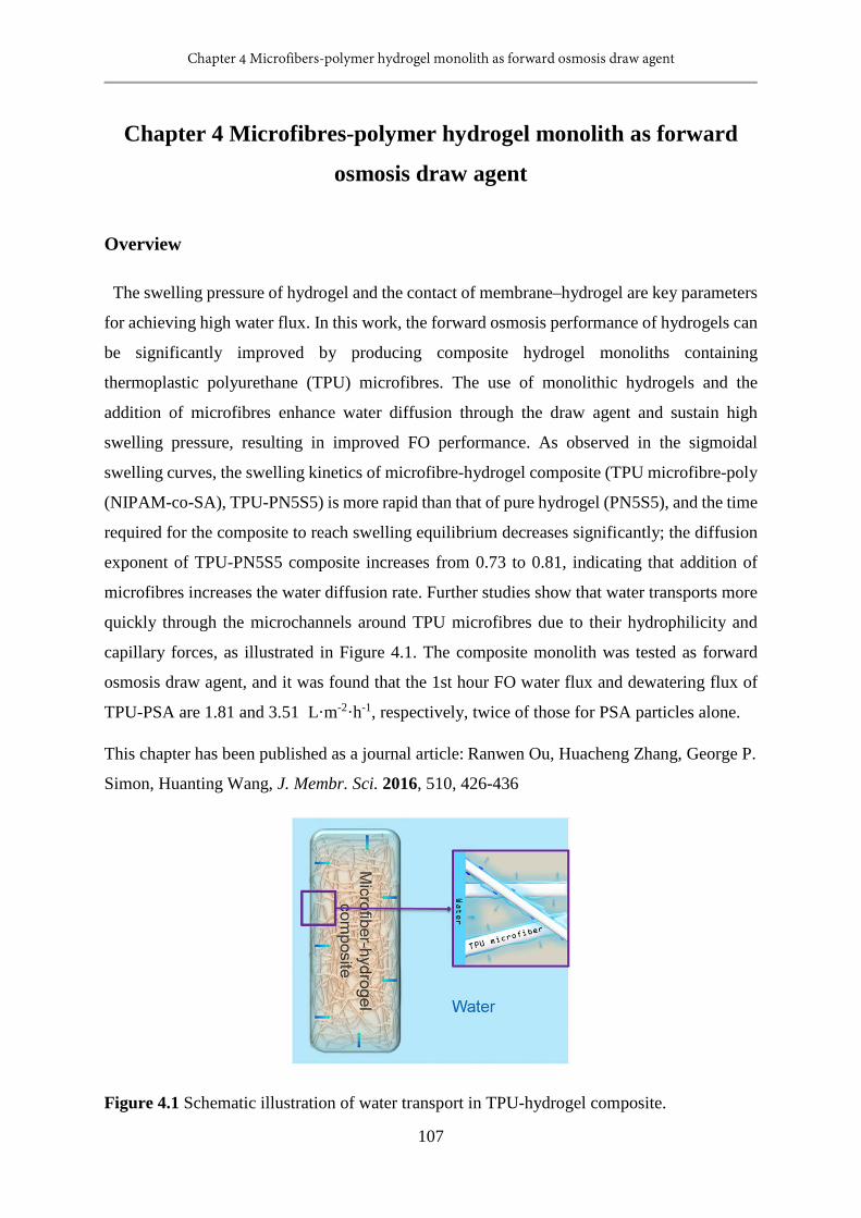
Chapter 4 Microfibers-polymer hydrogel monolith as forward osmosis draw agent
107
Chapter 4 Microfibres-polymer hydrogel monolith as forward
osmosis draw agent
Overview
The swelling pressure of hydrogel and the contact of membrane–hydrogel are key parameters
for achieving high water flux. In this work, the forward osmosis performance of hydrogels can
be significantly improved by producing composite hydrogel monoliths containing
thermoplastic polyurethane (TPU) microfibres. The use of monolithic hydrogels and the
addition of microfibres enhance water diffusion through the draw agent and sustain high
swelling pressure, resulting in improved FO performance. As observed in the sigmoidal
swelling curves, the swelling kinetics of microfibre-hydrogel composite (TPU microfibre-poly
(NIPAM-co-SA), TPU-PN5S5) is more rapid than that of pure hydrogel (PN5S5), and the time
required for the composite to reach swelling equilibrium decreases significantly; the diffusion
exponent of TPU-PN5S5 composite increases from 0.73 to 0.81, indicating that addition of
microfibres increases the water diffusion rate. Further studies show that water transports more
quickly through the microchannels around TPU microfibres due to their hydrophilicity and
capillary forces, as illustrated in Figure 4.1. The composite monolith was tested as forward
osmosis draw agent, and it was found that the 1st hour FO water flux and dewatering flux of
TPU-PSA are 1.81 and 3.51 L·m-2·h-1, respectively, twice of those for PSA particles alone.
This chapter has been published as a journal article: Ranwen Ou, Huacheng Zhang, George P.
Simon, Huanting Wang, J. Membr. Sci. 2016, 510, 426-436
Figure 4.1 Schematic illustration of water transport in TPU-hydrogel composite.
Chapter 4 Microfibers-polymer hydrogel monolith as forward osmosis draw agent
108
4.1 Introduction
Polymer hydrogels are three-dimensional networks of hydrophilic polymers, which can
become highly swollen in water or biological fluids. [1, 2] The unique properties of polymer
hydrogels, such as absorption, swelling and de-swelling behavior, hydrophilicity, and
biocompatibility, [3, 4] have been applied in many areas such as hygiene, pharmaceutical, drug
delivery, bio-sensors, artificial skin and muscles, the oil industry, agriculture, water treatment,
and textile manufacture. [5-8] Recently, our group have successfully demonstrated the
feasibility of using stimuli responsive polymer hydrogels as draw agent in the forward osmosis
(FO) desalination for the first time.[9] The FO process shows low membrane fouling propensity
and has potential to reduce water desalination and treatment costs.[10]
In the FO process, a draw agent is used to withdraw pure water from feed solution, while a
semipermeable membrane blocks the solute from the feed. Dry particles of cross-linked poly
(N-isopropyl acrylamide) (PNIPAM), poly (sodium acrylate) (PSA), and their copolymer have
been used for purifying brackish water. However, the properties of hydrogel draw agents need
to be improved to increase water flux for practical application. Thus, much effort has been
poured into investigating the relationship of water flux and hydrogel properties, and improving
the water flux. Research has shown that the swelling pressure of hydrogel, the contact of FO
membrane-hydrogel, and water transport through the draw agent are key factors affecting water
flux.[11-14] The contact of FO membrane-hydrogel indicates the percentage of contact area
between hydrogel and FO membrane to the FO membrane area.
A number of strategies, such as reducing the particle size of hydrogels and compressing
hydrogel particles into a monolith, have been demonstrated to improve the contact of FO
membrane-hydrogel and the water transport of draw agent. [12, 13, 15-18] In particular, the
addition of graphene into hydrogels greatly increased the softness of the composite hydrogels,
decreased the retractive force of polymer chains, and improved the inter-particle and particle-
membrane contacts, leading to significantly improved FO water fluxes.[13]
To maintain water flux in the FO process, the swelling pressure and water transport (or
swelling rate) of hydrogel draw agent need to be sustained. It is well known that the swelling
pressure of polymer hydrogels originates from polymer-water mixing, elastic reaction force of
the network, and osmotic pressure of ionizable groups.[14, 19] One effective methodology to
increase the swelling pressure of hydrogels is to increase the amount of ionic group in hydrogel,
which increases the osmotic pressure. For instance, the water flux of the copolymer hydrogel
Chapter 4 Microfibers-polymer hydrogel monolith as forward osmosis draw agent
109
of NIPAM and SA increases with increasing the amount of ionic SA. [9, 20] On the other hand,
significant efforts have been made to improve the polymer-water mixing rate and thus the
swelling and deswelling properties of hydrogels. By introducing porosity in hydrogel, the
interfacial contact between hydrogel and water is enhanced, giving rise to increased swelling
and deswelling rates. [21-23] Introduction of structural inhomogeneity in hydrogels is another
effective way to improve water diffusion. [24-26] In such hydrogels, the hydrophilic
component acts as a tunnel across the dense and hydrophobic layer at the surface of hydrogels,
accelerating water diffusion; the improvement of response rate of PNIPAM hydrogel can be
achieved by forming comb-type grafted networks to enhance mobility of grafted chains. [27,
28] These strategies are potentially useful for designing high-performance draw agents for FO
applications.
In this work, a new and effective method to sustain the swelling pressure is developed and
demonstrated by incorporating hydrophilic microfibres into a polymer hydrogel monolithic
draw agent. The incorporated microfibres provide a hydrophilic microfibre surface and
microchannel around the hydrogel phase, to advantageously directly transport water to the
inner part of hydrogel monolith, increasing the water diffusion, easing the restriction that
polymer chain relaxation causes, and maintaining the low swelling ratio of hydrogel contacted
with membrane. The microfibre-polymer monolith can be readily prepared by dispersion of
hydrophilic microfibres in aqueous monomer solution, and subsequent polymerization of
monomers, and this preparation process allows for tuning of compositions of hydrogels
(content of ionic monomer) and loading of microfibres. In this study, thermoplastic
polyurethane (TPU) was chosen as microfibre material for its good elasticity, high wear
resistance, good oil and grease resistance and low cost. The TPU microfibres used in this
experiment were prepared by force spinning, which is a fast and efficient technique to produce
micro- and nano-scale fibres. [29, 30] The swelling behavior and mechanisms of pure
hydrogels and composite hydrogels are studied. The composite hydrogel is applied as a draw
agent in FO process to quantify the improvement in the swelling pressure and water flux.

Chapter 4 Microfibers-polymer hydrogel monolith as forward osmosis draw agent
110
4.2 Experimental
4.2.1 Materials
N-isopropyl acrylamide (NIPAM, 97 %), Sodium acrylate (SA, 97 %), N, N-methylenebis
(acrylamide) (MBA, 99 %), ammonium persulfate (APS, ≥ 98 %), and N, N, N’, N’-tetramethyl
ethylenediamine (TEMED, 99 %) were purchased from Sigma-Aldrich Australia.
Thermoplastic polyurethane (TPU, TETON*206) was kindly provided by Urethane
Compounds Pty. Ltd Australia. Tetrahydrofuran (THF) was purchased from Merck. Pure water
was used in all experiments. All the chemicals mentioned above were used without further
purification.
4.2.2 Experimental procedures
Preparation of pure hydrogel: A 16.67 wt. % monomer solution was prepared by dissolving
monomer (NIPAM, SA), cross-linker (MBA), and initiator (APS) in deionized water. The
weight ratio of monomer, cross-linker, and initiator was fixed at 50:1:0.5. The composition of
NIPAM and SA is shown in Table 4.1. A drop of TEMED was added into the monomer solution
under mild shaking to accelerate the initiation of the polymerization reaction. The hydrogels
were formed within a few minutes, followed by rinsing with deionized water and drying in a
60 °C oven. The dry hydrogel was ground into particles for use as a draw agent. The average
particle sizes of PNIPAM, PN7S3, PN5S5, PN3S7, and PSA were 20.9, 23.5, 12.8, 21.7, and
39.8 µm, respectively.
Table 4.1 Composition of pure hydrogels and composite hydrogels.
Pure
hydrogels
N-isopropyl
acrylamide
(wt. %)
Sodium
acrylate
(wt. %)
Composite
hydrogels
TPU
microfibre
(wt. %)
N-isopropyl
acrylamide
(wt. %)
Sodium
acrylate
(wt. %)
PNIPAM 100 0 TPU-PNIPAM 50 50 0
PN7S3 70 30 TPU-PN7S3 50 35 15
PN5S5 50 50 TPU-PN5S5 50 25 25
PN3S7 30 70 TPU-PN3S7 50 15 35
Preparation of TPU microfibre-hydrogel composite: TPU was dissolved in THF to form a 12
wt. % polymer solution. The solution was spun into a TPU microfibre mat by a force spinner
(Cyclone L-1000M, FibeRio® Technology Corporation, USA). At a rotational speed of 5000

Chapter 4 Microfibers-polymer hydrogel monolith as forward osmosis draw agent
111
rpm, 1 g of microfibre was formed in less than 30 seconds. The diameter distribution of TPU
microfibre used in this study is 0.5-50 µm.
Figure 4.2 The preparation process of TPU-hydrogel composites.
To make the composite, a drop of TEMED was added to the monomer solution. After mild
shaking, the TPU microfibre was immersed into the solution and a few minutes later, the
composite monolith was formed. The composite hydrogel was washed with pure water before
use. For the composites used as draw agent, in order to get better contact of composite - FO
membrane, the composite monolith was prepared on the membrane in the FO cell. The
preparation process of TPU microfibre-hydrogel composite draw agent is shown in Figure 4.2.
The FO performances of PN5S5 particles and TPU-PN5S5 composites with 0, 30, 50, and 70
wt. % TPU microfibre loading were tested (Figure 4.3), the results suggest that those with 50
wt. % TPU microfibre loading performed the best. Thus the TPU-hydrogel with 50 wt. % TPU
loading, as shown in Table 4.1, was used in the following study as comparison with hydrogel
particles.
Figure 4.3 Water flux of PN5S5 hydrogel particle and PN5S5 composite hydrogels with
different TPU loadings.
Chapter 4 Microfibers-polymer hydrogel monolith as forward osmosis draw agent
112
Characterization: The morphology of pure hydrogel particles and TPU microfibre-hydrogel
composites was observed by a scanning electron microscope (Nova NanoSEM 450 FESEM,
FEI, USA). The diameters of TPU microfibres were determined by the Nano Measurer 1.2. A
contact angle goniometer (Dataphysics OCA15, Dataphysics, Germany) was used to determine
the wettability of TPU microfibre mat and hydrogels. An industrial incandescent lamp (IR 250
C, 230 V, 250 W, Philips) was used as the light source for dewatering the hydrogel draw agents,
as part of the FO process, and a radiometer (FZ-A) was used to determine the light intensity.
The swelling ratio and FO water flux were measured and calculated as in our previous study.
[13, 17] The swelling ratio Q (g/g) was determined by weighing the dry hydrogels and swollen
hydrogels over a period of time; the swollen hydrogels were kept in deionized water for 3 days
and the water was replaced with fresh deionized water every day.
Forward osmosis tests were carried out in a homemade FO cell, as shown in Figure 4.2. The
active surface of the FO membrane (CTA membrane, Hydration Technologies Inc., Albany,
OR) was faced to feed solution. 0.5 g of dry pure hydrogel particle was used in the test. 1 g of
TPU-hydrogel composite composed of 0.5 g of TPU microfibres and 0.5 g of hydrogel, with
different initial water contents was used as draw agent in the test. 2000 ppm NaCl solution was
used as feed water in the measurements. The FO water flux, F (L·m-2·h-1, or LMH), was
determined by the weight change of the FO cell over a period of time. The effective area of the
FO membrane was 4.91 cm2.
In the dewatering process, the FO cell with swollen hydrogel was put under an incandescent
lamp. The light intensity on the hydrogel surface was fixed at 1 kW·m-2 and the weight loss as
a function of time recorded. The averaging dewatering flux (Fd, LMH) was calculated by
equation:
tAVFd×
= (1)
where V (L) is the volume loss of hydrogel in the dewatering process over a period of time t
(h). The FO cell was moved to dewater directly, so the effective area A (m2) is 4.91 cm2.

Chapter 4 Microfibers-polymer hydrogel monolith as forward osmosis draw agent
113
4.3 Results and discussion
4.3.1 Morphology of composite hydrogels
The morphology of TPU microfibres and composite hydrogels was observed using scanning
electron microscopy, with the results shown in Figure 4.4. Figure 4.4a demonstrates that the
diameter of TPU microfibre is unevenly distributed, their diameter ranging from 0.5 to 50 µm.
Figure 4.4b-f show the cross-section of TPU-hydrogel composites. In such dry composites, the
TPU microfibres are dispersed within the hydrogel, and a gap can be seen between the
microfibre and hydrogel.
Figure 4.4 SEM images of TPU microfibres and cross-section of composite hydrogels. (a) TPU
microfibres, (b) TPU-PNIPAM composite, (c) TPU-PN7S3 composite, (d) TPU-PN5S5
composite, (e) TPU-PN3S7 composite, and (f) TPU-PSA composite. The gaps between the
microfibre and the hydrogel are indicated by arrows.
4.3.2 Swelling properties of hydrogels
The swelling ratio of the composite hydrogels is half of that of corresponding pure hydrogels,
as shown in Figure 4.5. Since the composite hydrogels contain 50 wt. % TPU microfibre and
50 wt. % hydrogel, and TPU microfibre does not swell in water to the same degree as a hydrogel,
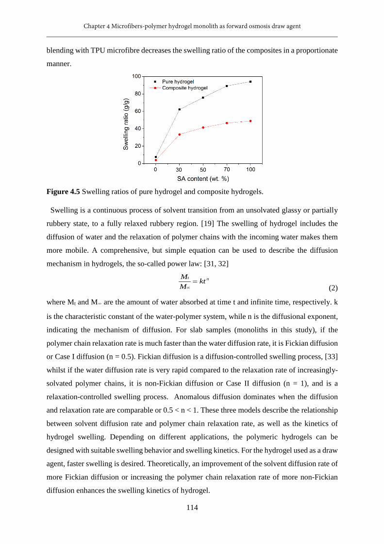
Chapter 4 Microfibers-polymer hydrogel monolith as forward osmosis draw agent
114
blending with TPU microfibre decreases the swelling ratio of the composites in a proportionate
manner.
Figure 4.5 Swelling ratios of pure hydrogel and composite hydrogels.
Swelling is a continuous process of solvent transition from an unsolvated glassy or partially
rubbery state, to a fully relaxed rubbery region. [19] The swelling of hydrogel includes the
diffusion of water and the relaxation of polymer chains with the incoming water makes them
more mobile. A comprehensive, but simple equation can be used to describe the diffusion
mechanism in hydrogels, the so-called power law: [31, 32]
nt ktMM
=∞ (2)
where Mt and M∞ are the amount of water absorbed at time t and infinite time, respectively. k
is the characteristic constant of the water-polymer system, while n is the diffusional exponent,
indicating the mechanism of diffusion. For slab samples (monoliths in this study), if the
polymer chain relaxation rate is much faster than the water diffusion rate, it is Fickian diffusion
or Case I diffusion (n = 0.5). Fickian diffusion is a diffusion-controlled swelling process, [33]
whilst if the water diffusion rate is very rapid compared to the relaxation rate of increasingly-
solvated polymer chains, it is non-Fickian diffusion or Case II diffusion (n = 1), and is a
relaxation-controlled swelling process. Anomalous diffusion dominates when the diffusion
and relaxation rate are comparable or 0.5 < n < 1. These three models describe the relationship
between solvent diffusion rate and polymer chain relaxation rate, as well as the kinetics of
hydrogel swelling. Depending on different applications, the polymeric hydrogels can be
designed with suitable swelling behavior and swelling kinetics. For the hydrogel used as a draw
agent, faster swelling is desired. Theoretically, an improvement of the solvent diffusion rate of
more Fickian diffusion or increasing the polymer chain relaxation rate of more non-Fickian
diffusion enhances the swelling kinetics of hydrogel.
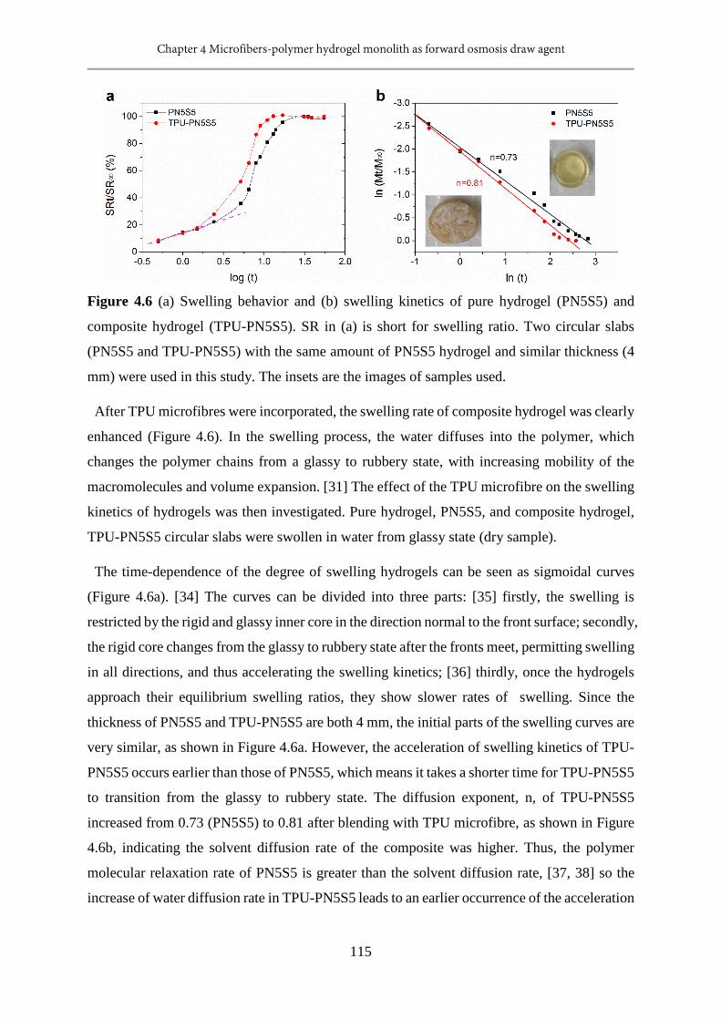
Chapter 4 Microfibers-polymer hydrogel monolith as forward osmosis draw agent
115
Figure 4.6 (a) Swelling behavior and (b) swelling kinetics of pure hydrogel (PN5S5) and
composite hydrogel (TPU-PN5S5). SR in (a) is short for swelling ratio. Two circular slabs
(PN5S5 and TPU-PN5S5) with the same amount of PN5S5 hydrogel and similar thickness (4
mm) were used in this study. The insets are the images of samples used.
After TPU microfibres were incorporated, the swelling rate of composite hydrogel was clearly
enhanced (Figure 4.6). In the swelling process, the water diffuses into the polymer, which
changes the polymer chains from a glassy to rubbery state, with increasing mobility of the
macromolecules and volume expansion. [31] The effect of the TPU microfibre on the swelling
kinetics of hydrogels was then investigated. Pure hydrogel, PN5S5, and composite hydrogel,
TPU-PN5S5 circular slabs were swollen in water from glassy state (dry sample).
The time-dependence of the degree of swelling hydrogels can be seen as sigmoidal curves
(Figure 4.6a). [34] The curves can be divided into three parts: [35] firstly, the swelling is
restricted by the rigid and glassy inner core in the direction normal to the front surface; secondly,
the rigid core changes from the glassy to rubbery state after the fronts meet, permitting swelling
in all directions, and thus accelerating the swelling kinetics; [36] thirdly, once the hydrogels
approach their equilibrium swelling ratios, they show slower rates of swelling. Since the
thickness of PN5S5 and TPU-PN5S5 are both 4 mm, the initial parts of the swelling curves are
very similar, as shown in Figure 4.6a. However, the acceleration of swelling kinetics of TPU-
PN5S5 occurs earlier than those of PN5S5, which means it takes a shorter time for TPU-PN5S5
to transition from the glassy to rubbery state. The diffusion exponent, n, of TPU-PN5S5
increased from 0.73 (PN5S5) to 0.81 after blending with TPU microfibre, as shown in Figure
4.6b, indicating the solvent diffusion rate of the composite was higher. Thus, the polymer
molecular relaxation rate of PN5S5 is greater than the solvent diffusion rate, [37, 38] so the
increase of water diffusion rate in TPU-PN5S5 leads to an earlier occurrence of the acceleration

Chapter 4 Microfibers-polymer hydrogel monolith as forward osmosis draw agent
116
swelling process. Due to the benefit of the increased rate of water diffusion, the composite
reached equilibrium swelling after 11 h, while the pure hydrogel equilibrium took 17 h.
4.3.3 Water diffusion in composite hydrogels
In the following section, the mechanism of the water diffusion improvement by incorporating
TPU microfibres will be discussed. Figure 4.7 shows the wettability of TPU microfibre and the
water absorbing ability of hydrogels, which indicates the enhanced absorbing ability of
composite hydrogels is related to the wettability of TPU microfibres. The dry TPU microfibres
are hydrophobic, as shown in Figure 4.7a, the water contact angle of dry TPU microfibre
changing only slightly after 5 minutes test. However, when the microfibres become totally wet,
the water droplet spread on the microfibres in less than 0.1 second, demonstrating that the wet
TPU microfibre is hydrophilic.
Figure 4.7 Wettability of TPU microfibres and water absorption ability of hydrogels. (a) Plot
of contact angle versus time of dry TPU microfibre and wet TPU microfibre. (b) Time needed
for absorbing a 3 µL water droplet by dry pure hydrogels, wet pure hydrogel and wet composite
hydrogels. The wet hydrogels contained 50 wt. % water. Contact angle goniometer was used
to control the volume of water droplets and observe the absorbing process.
To test the water absorbing ability of hydrogels, a 3 µL water droplet was dropped on the
surface of pure hydrogels and composite hydrogels (slabs), and the time required for the water
droplet to be absorbed recorded. The results in Figure 4.7b show that: 1) the absorption time
decreases with increasing the SA content of hydrogels; 2) the water absorption ability of wet
composite hydrogel is much better than that of dry pure hydrogels or pure hydrogels containing
50 wt. % water. The water absorption ability of composite hydrogels is much greater than that
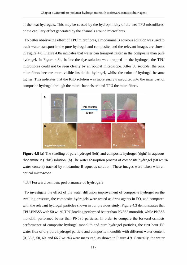
Chapter 4 Microfibers-polymer hydrogel monolith as forward osmosis draw agent
117
of the neat hydrogels. This may be caused by the hydrophilicity of the wet TPU microfibres,
or the capillary effect generated by the channels around microfibres.
To better observe the effect of TPU microfibres, a rhodamine B aqueous solution was used to
track water transport in the pure hydrogel and composite, and the relevant images are shown
in Figure 4.8. Figure 4.8a indicates that water can transport faster in the composite than pure
hydrogel. In Figure 4.8b, before the dye solution was dropped on the hydrogel, the TPU
microfibres could not be seen clearly by an optical microscope. After 50 seconds, the pink
microfibres became more visible inside the hydrogel, whilst the color of hydrogel became
lighter. This indicates that the RhB solution was more easily transported into the inner part of
composite hydrogel through the microchannels around TPU the microfibres.
Figure 4.8 (a) The swelling of pure hydrogel (left) and composite hydrogel (right) in aqueous
rhodamine B (RhB) solution. (b) The water absorption process of composite hydrogel (50 wt. %
water content) tracked by rhodamine B aqueous solution. These images were taken with an
optical microscope.
4.3.4 Forward osmosis performance of hydrogels
To investigate the effect of the water diffusion improvement of composite hydrogel on the
swelling pressure, the composite hydrogels were tested as draw agents in FO, and compared
with the relevant hydrogel particles shown in our previous study. Figure 4.3 demonstrates that
TPU-PN5S5 with 50 wt. % TPU loading performed better than PN5S5 monolith, while PN5S5
monolith performed better than PN5S5 particles. In order to compare the forward osmosis
performance of composite hydrogel monolith and pure hydrogel particles, the first hour FO
water flux of dry pure hydrogel particle and composite monolith with different water content
(0, 33.3, 50, 60, and 66.7 wt. %) were measured, as shown in Figure 4.9. Generally, the water
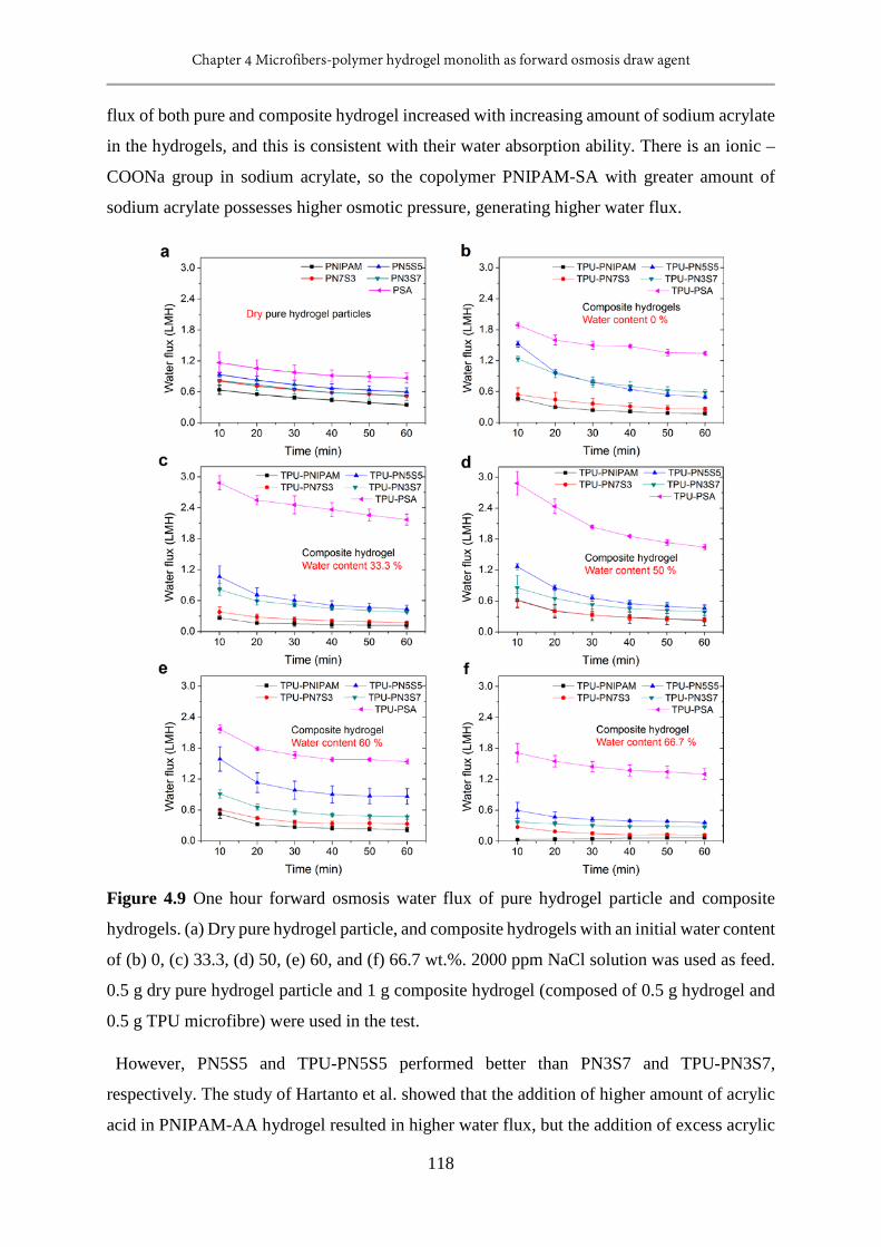
Chapter 4 Microfibers-polymer hydrogel monolith as forward osmosis draw agent
118
flux of both pure and composite hydrogel increased with increasing amount of sodium acrylate
in the hydrogels, and this is consistent with their water absorption ability. There is an ionic –
COONa group in sodium acrylate, so the copolymer PNIPAM-SA with greater amount of
sodium acrylate possesses higher osmotic pressure, generating higher water flux.
Figure 4.9 One hour forward osmosis water flux of pure hydrogel particle and composite
hydrogels. (a) Dry pure hydrogel particle, and composite hydrogels with an initial water content
of (b) 0, (c) 33.3, (d) 50, (e) 60, and (f) 66.7 wt.%. 2000 ppm NaCl solution was used as feed.
0.5 g dry pure hydrogel particle and 1 g composite hydrogel (composed of 0.5 g hydrogel and
0.5 g TPU microfibre) were used in the test.
However, PN5S5 and TPU-PN5S5 performed better than PN3S7 and TPU-PN3S7,
respectively. The study of Hartanto et al. showed that the addition of higher amount of acrylic
acid in PNIPAM-AA hydrogel resulted in higher water flux, but the addition of excess acrylic

Chapter 4 Microfibers-polymer hydrogel monolith as forward osmosis draw agent
119
acid from 50 % to 70 % appears to have limited impact on the water flux. [15] Note that the
FO water flux depends on not only the osmotic pressure of hydrogel, but also on the contact of
membrane–hydrogel. Figure 4.10 shows that the particle size of PN5S5 is smaller than that of
PN3S7, thus, the PN5S5 particle generated higher flux due to better contact. The average
particle size of PNIPAM, PN7S3, PN5S5, PN3S7, and PSA were 20.9, 23.5, 12.8, 21.7, and
39.8 µm, respectively, determined by Nano Measurer 1.2. Importantly, the TPU-hydrogel
composite was monolithic. Higher water fluxes of TPU-PN5S5 may be caused by better contact
of the membrane and composite than that of TPU-PN3S7.
Figure 4.10 SEM images of pure hydrogel particles. (a) PNIPAM, (b) PN7S3, (c) PN5S5, (d)
PN3S7, and (e) PSA.
Compared to dry pure hydrogel particles, composite hydrogels performed better in the FO
process. In the first 10 minutes of the FO test, the water flux of PNIPAM, PN7S3, PN5S5,
PN3S7, and PSA particle were 0.64, 0.81, 0.94, 0.83, and 1.17 LMH, respectively; while those
of relevant dry composite hydrogels were 0.46, 0.54, 1.52, 1.23, and 1.89 LMH, individually.
Among the hydrogels, TPU-PSA exhibited greatly enhanced water flux compared to other
composites and PSA particles. With the increased initial water content, the first 10 minutes
water flux of TPU-PSA increased from 1.89 LMH to 2.88 LMH (33.3 and 50 wt. % water
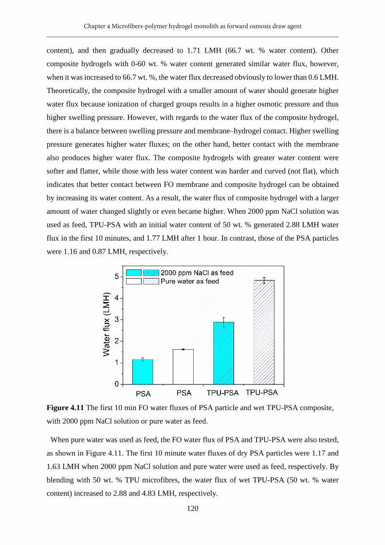
Chapter 4 Microfibers-polymer hydrogel monolith as forward osmosis draw agent
120
content), and then gradually decreased to 1.71 LMH (66.7 wt. % water content). Other
composite hydrogels with 0-60 wt. % water content generated similar water flux, however,
when it was increased to 66.7 wt. %, the water flux decreased obviously to lower than 0.6 LMH.
Theoretically, the composite hydrogel with a smaller amount of water should generate higher
water flux because ionization of charged groups results in a higher osmotic pressure and thus
higher swelling pressure. However, with regards to the water flux of the composite hydrogel,
there is a balance between swelling pressure and membrane–hydrogel contact. Higher swelling
pressure generates higher water fluxes; on the other hand, better contact with the membrane
also produces higher water flux. The composite hydrogels with greater water content were
softer and flatter, while those with less water content was harder and curved (not flat), which
indicates that better contact between FO membrane and composite hydrogel can be obtained
by increasing its water content. As a result, the water flux of composite hydrogel with a larger
amount of water changed slightly or even became higher. When 2000 ppm NaCl solution was
used as feed, TPU-PSA with an initial water content of 50 wt. % generated 2.88 LMH water
flux in the first 10 minutes, and 1.77 LMH after 1 hour. In contrast, those of the PSA particles
were 1.16 and 0.87 LMH, respectively.
Figure 4.11 The first 10 min FO water fluxes of PSA particle and wet TPU-PSA composite,
with 2000 ppm NaCl solution or pure water as feed.
When pure water was used as feed, the FO water flux of PSA and TPU-PSA were also tested,
as shown in Figure 4.11. The first 10 minute water fluxes of dry PSA particles were 1.17 and
1.63 LMH when 2000 ppm NaCl solution and pure water were used as feed, respectively. By
blending with 50 wt. % TPU microfibres, the water flux of wet TPU-PSA (50 wt. % water
content) increased to 2.88 and 4.83 LMH, respectively.

Chapter 4 Microfibers-polymer hydrogel monolith as forward osmosis draw agent
121
Figure 4.12a-b shows the 24 hours FO performance of hydrogels. For pure hydrogel particle,
PSA showed highest water flux. It generated 1.17 LMH water flux in the first 10 minutes, 0.53
LMH after 5 hours, and 0.27 LMH after 24 hours. In the test, TPU-PSA monolith showed the
highest FO water flux among 10 hydrogels. It generated a water flux of 2.77 LMH, 1.28 LMH
and 0.80 LMH in the first 10 minutes, after 5 hours, and after 24 hours, respectively. These
values are about twice as large as those of PSA hydrogel particles. In previous study, the water
flux of hydrogel particles dropt very fast to below 1 LMH in less than 5 hours. For example,
as shown in Table 4.2, it takes 1, 3, 5, and 4 hours for PSA, [9] PSA-C, [17], PSA-rGO [13]
hydrogel particles, and MCG-NP50-AA50 microgels [15] to drop down to less than 1 LMH,
respectively. However, TPU-PSA maintained a water flux of > 1 LMH in the first 12 hours,
which benefits from the good water transport system.
Table 4.2. The water flux of hydrogel draw agent in recent publications.
Draw agent Water flux (LMH)
Ref. 1st hour 5th hour
PSA particles 0.96 0.58 [9]
PSA-Carbon paticles 1.05 0.80 [17]
PSA-rGO 3.1 0.95 [13]
PNIPAM-SA-iron oxide 1.48 0.70 [18]
PNIPAM-SA microgels 4 -- [15]
PNIPAM-SI-0.5 PVA 0.24 0.08 [16]
TPU-PSA 2.17 1.28 This
work
After the FO process, all the water absorbed by the hydrogels was dewatered using an
industrial incandescent lamp (1 kW·m-2 sunlight), and the average dewatering flux is shown in
Figure 4.12c-d. In a practical application, the dewatering could be achieved by combining the
solar energy and industrial waste heat. As shown in Figure 4.12c-d, the average dewatering
flux of composite hydrogels is slightly higher than those of pure hydrogel particle. Surprisingly,
PSA showed the highest dewatering flux among the pure hydrogel particles, but not for
PNIPAM. PNIPAM is a temperature-responsive hydrogel, swollen PNIPAM hydrogel particle
dewaters most of the water absorbed easily by heat it over its lower critical solution temperature
(LCST); however, it is difficult to dewater all the water from it. When PNIPAM is heated above
the LCST, a hydrophobic layer will be formed at the surface of hydrogel that limits the outward
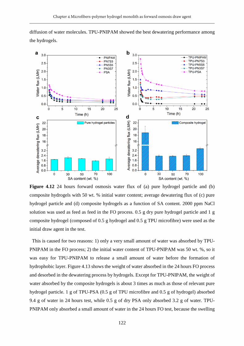
Chapter 4 Microfibers-polymer hydrogel monolith as forward osmosis draw agent
122
diffusion of water molecules. TPU-PNIPAM showed the best dewatering performance among
the hydrogels.
Figure 4.12 24 hours forward osmosis water flux of (a) pure hydrogel particle and (b)
composite hydrogels with 50 wt. % initial water content; average dewatering flux of (c) pure
hydrogel particle and (d) composite hydrogels as a function of SA content. 2000 ppm NaCl
solution was used as feed as feed in the FO process. 0.5 g dry pure hydrogel particle and 1 g
composite hydrogel (composed of 0.5 g hydrogel and 0.5 g TPU microfibre) were used as the
initial draw agent in the test.
This is caused for two reasons: 1) only a very small amount of water was absorbed by TPU-
PNIPAM in the FO process; 2) the initial water content of TPU-PNIPAM was 50 wt. %, so it
was easy for TPU-PNIPAM to release a small amount of water before the formation of
hydrophobic layer. Figure 4.13 shows the weight of water absorbed in the 24 hours FO process
and desorbed in the dewatering process by hydrogels. Except for TPU-PNIPAM, the weight of
water absorbed by the composite hydrogels is about 3 times as much as those of relevant pure
hydrogel particle. 1 g of TPU-PSA (0.5 g of TPU microfibre and 0.5 g of hydrogel) absorbed
9.4 g of water in 24 hours test, while 0.5 g of dry PSA only absorbed 3.2 g of water. TPU-
PNIPAM only absorbed a small amount of water in the 24 hours FO test, because the swelling

Chapter 4 Microfibers-polymer hydrogel monolith as forward osmosis draw agent
123
pressure generated by wet TPU-PNIPAM is small. The initial water content of composite
hydrogels used in the test was 50 wt. %, and the relevant swelling ratio was 1 g/g, while the
equilibrium swelling ratio of TPU-PNIPAM is 3.9 g/g. It takes a few days for the TPU-
PNIPAM to reach swelling equilibrium by immersing it in water. Thus, it is difficult for wet
TPU-PNIPAM to generate high FO fluxes. After the FO test, all the water absorbed in the FO
process was desorbed in the dewatering process. The percentage of liquid water recovery is
shown in Figure 4.14, after combining the TPU microfibre and hydrogel, it is slightly increased.
Figure 4.13 Forward osmosis and solar dewatering performance of pure hydrogel particle
and composite hydrogels. 2000 ppm NaCl solution was used as feed in the FO process. The
dewatering process was tested under 1 kW·m-2 incandescent lamp. (a) Weight of water
absorbed or desorbed by the pure hydrogel particles in the FO and dewatering process. 0.5 g
dry pure hydrogel particle was used in the test. (b) Weight of water absorbed or desorbed by
the composite hydrogels in the FO and dewatering process. 1 g composite hydrogel
(composed of 0.5 g hydrogel and 0.5 g TPU microfibre) with 50 wt. % initial water content
was used in the test.
The temperature change of hydrogels in one hour dewatering process was measured, as shown
in Figure 4.15. 2.5 g of water was added to 0.5 g of hydrogel particle or 1 g of composite
hydrogel to obtain a swollen hydrogel before this test. The water content of hydrogel particle
and hydrogel of the composite were the same. The test was conducted under 1 kW·m-2
incandescent lamp. After 6 minutes, the composite hydrogels reached their highest temperature.
Thereafter, the temperature of composite hydrogel decreased with time, likely due to the
decreasing water content of hydrogels. However, the temperature of swollen pure hydrogel
particles increased in the first 20 minutes, and then remained constant. The highest
temperatures of composite hydrogels were greater than those of relevant pure hydrogel
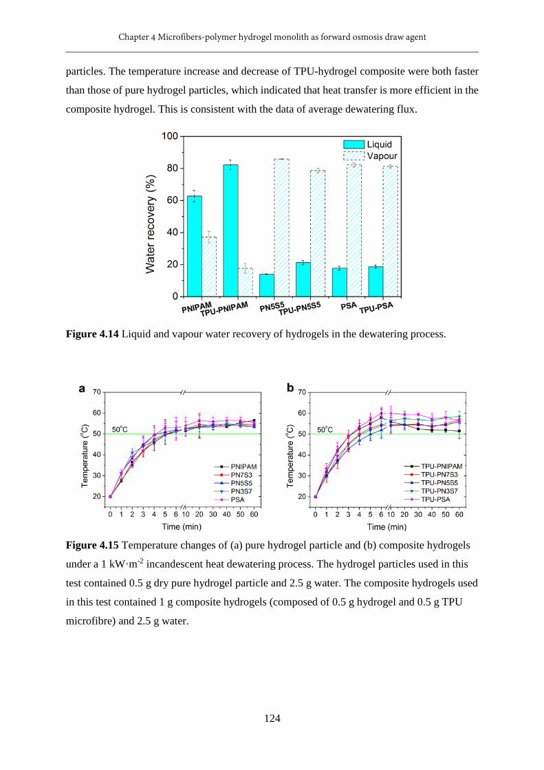
Chapter 4 Microfibers-polymer hydrogel monolith as forward osmosis draw agent
124
particles. The temperature increase and decrease of TPU-hydrogel composite were both faster
than those of pure hydrogel particles, which indicated that heat transfer is more efficient in the
composite hydrogel. This is consistent with the data of average dewatering flux.
Figure 4.14 Liquid and vapour water recovery of hydrogels in the dewatering process.
Figure 4.15 Temperature changes of (a) pure hydrogel particle and (b) composite hydrogels
under a 1 kW·m-2 incandescent heat dewatering process. The hydrogel particles used in this
test contained 0.5 g dry pure hydrogel particle and 2.5 g water. The composite hydrogels used
in this test contained 1 g composite hydrogels (composed of 0.5 g hydrogel and 0.5 g TPU
microfibre) and 2.5 g water.
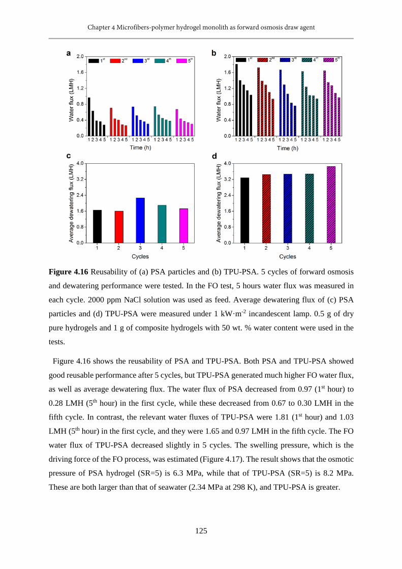
Chapter 4 Microfibers-polymer hydrogel monolith as forward osmosis draw agent
125
Figure 4.16 Reusability of (a) PSA particles and (b) TPU-PSA. 5 cycles of forward osmosis
and dewatering performance were tested. In the FO test, 5 hours water flux was measured in
each cycle. 2000 ppm NaCl solution was used as feed. Average dewatering flux of (c) PSA
particles and (d) TPU-PSA were measured under 1 kW·m-2 incandescent lamp. 0.5 g of dry
pure hydrogels and 1 g of composite hydrogels with 50 wt. % water content were used in the
tests.
Figure 4.16 shows the reusability of PSA and TPU-PSA. Both PSA and TPU-PSA showed
good reusable performance after 5 cycles, but TPU-PSA generated much higher FO water flux,
as well as average dewatering flux. The water flux of PSA decreased from 0.97 (1st hour) to
0.28 LMH (5th hour) in the first cycle, while these decreased from 0.67 to 0.30 LMH in the
fifth cycle. In contrast, the relevant water fluxes of TPU-PSA were 1.81 (1st hour) and 1.03
LMH (5th hour) in the first cycle, and they were 1.65 and 0.97 LMH in the fifth cycle. The FO
water flux of TPU-PSA decreased slightly in 5 cycles. The swelling pressure, which is the
driving force of the FO process, was estimated (Figure 4.17). The result shows that the osmotic
pressure of PSA hydrogel (SR=5) is 6.3 MPa, while that of TPU-PSA (SR=5) is 8.2 MPa.
These are both larger than that of seawater (2.34 MPa at 298 K), and TPU-PSA is greater.
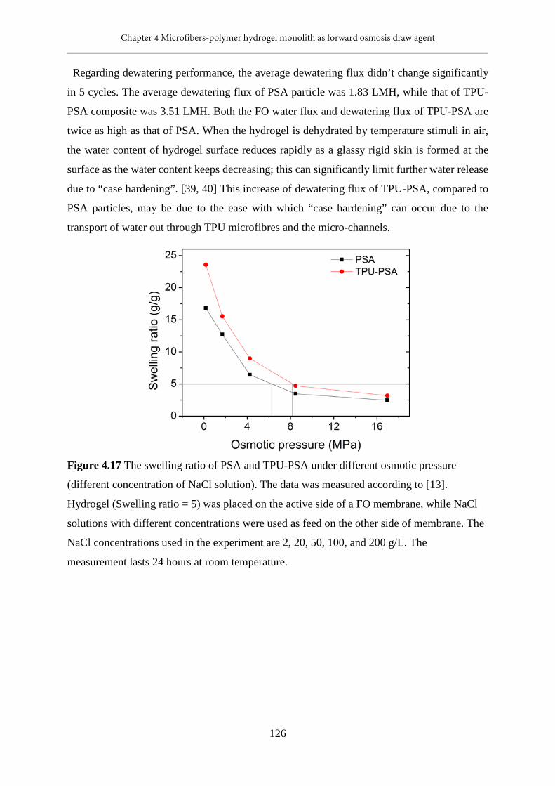
Chapter 4 Microfibers-polymer hydrogel monolith as forward osmosis draw agent
126
Regarding dewatering performance, the average dewatering flux didn’t change significantly
in 5 cycles. The average dewatering flux of PSA particle was 1.83 LMH, while that of TPU-
PSA composite was 3.51 LMH. Both the FO water flux and dewatering flux of TPU-PSA are
twice as high as that of PSA. When the hydrogel is dehydrated by temperature stimuli in air,
the water content of hydrogel surface reduces rapidly as a glassy rigid skin is formed at the
surface as the water content keeps decreasing; this can significantly limit further water release
due to “case hardening”. [39, 40] This increase of dewatering flux of TPU-PSA, compared to
PSA particles, may be due to the ease with which “case hardening” can occur due to the
transport of water out through TPU microfibres and the micro-channels.
Figure 4.17 The swelling ratio of PSA and TPU-PSA under different osmotic pressure
(different concentration of NaCl solution). The data was measured according to [13].
Hydrogel (Swelling ratio = 5) was placed on the active side of a FO membrane, while NaCl
solutions with different concentrations were used as feed on the other side of membrane. The
NaCl concentrations used in the experiment are 2, 20, 50, 100, and 200 g/L. The
measurement lasts 24 hours at room temperature.
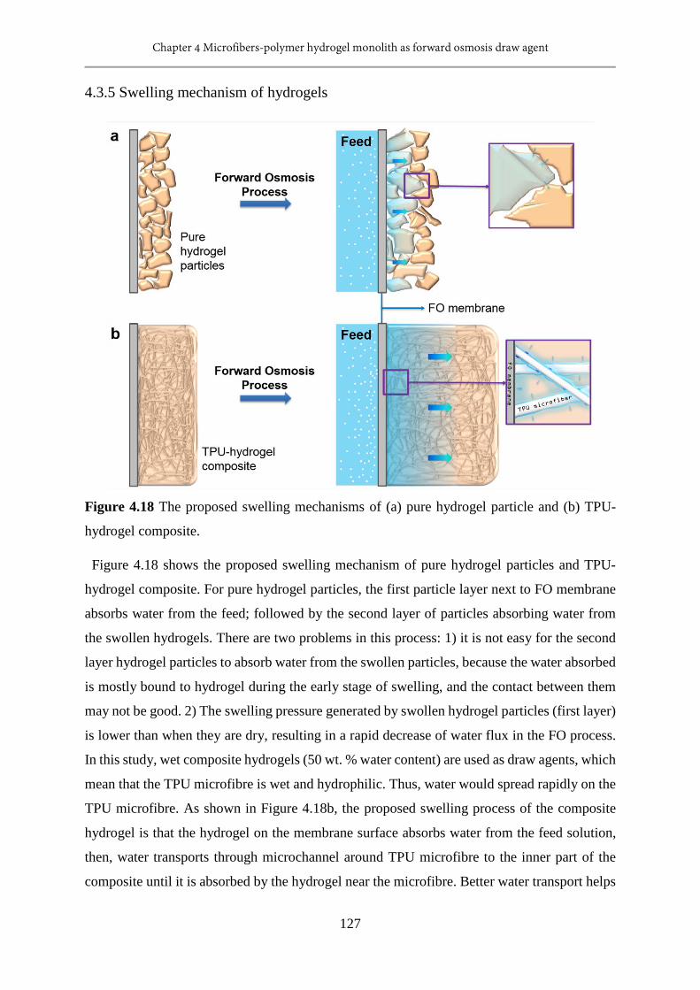
Chapter 4 Microfibers-polymer hydrogel monolith as forward osmosis draw agent
127
4.3.5 Swelling mechanism of hydrogels
Figure 4.18 The proposed swelling mechanisms of (a) pure hydrogel particle and (b) TPU-
hydrogel composite.
Figure 4.18 shows the proposed swelling mechanism of pure hydrogel particles and TPU-
hydrogel composite. For pure hydrogel particles, the first particle layer next to FO membrane
absorbs water from the feed; followed by the second layer of particles absorbing water from
the swollen hydrogels. There are two problems in this process: 1) it is not easy for the second
layer hydrogel particles to absorb water from the swollen particles, because the water absorbed
is mostly bound to hydrogel during the early stage of swelling, and the contact between them
may not be good. 2) The swelling pressure generated by swollen hydrogel particles (first layer)
is lower than when they are dry, resulting in a rapid decrease of water flux in the FO process.
In this study, wet composite hydrogels (50 wt. % water content) are used as draw agents, which
mean that the TPU microfibre is wet and hydrophilic. Thus, water would spread rapidly on the
TPU microfibre. As shown in Figure 4.18b, the proposed swelling process of the composite
hydrogel is that the hydrogel on the membrane surface absorbs water from the feed solution,
then, water transports through microchannel around TPU microfibre to the inner part of the
composite until it is absorbed by the hydrogel near the microfibre. Better water transport helps
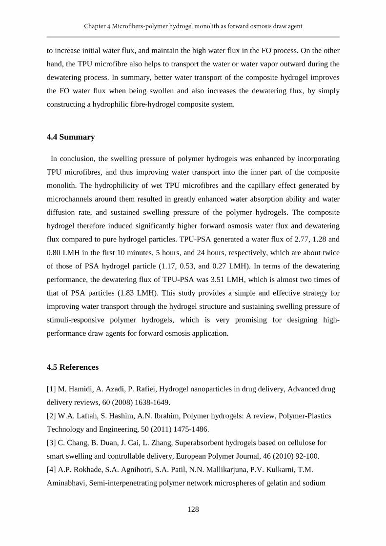
Chapter 4 Microfibers-polymer hydrogel monolith as forward osmosis draw agent
128
to increase initial water flux, and maintain the high water flux in the FO process. On the other
hand, the TPU microfibre also helps to transport the water or water vapor outward during the
dewatering process. In summary, better water transport of the composite hydrogel improves
the FO water flux when being swollen and also increases the dewatering flux, by simply
constructing a hydrophilic fibre-hydrogel composite system.
4.4 Summary
In conclusion, the swelling pressure of polymer hydrogels was enhanced by incorporating
TPU microfibres, and thus improving water transport into the inner part of the composite
monolith. The hydrophilicity of wet TPU microfibres and the capillary effect generated by
microchannels around them resulted in greatly enhanced water absorption ability and water
diffusion rate, and sustained swelling pressure of the polymer hydrogels. The composite
hydrogel therefore induced significantly higher forward osmosis water flux and dewatering
flux compared to pure hydrogel particles. TPU-PSA generated a water flux of 2.77, 1.28 and
0.80 LMH in the first 10 minutes, 5 hours, and 24 hours, respectively, which are about twice
of those of PSA hydrogel particle (1.17, 0.53, and 0.27 LMH). In terms of the dewatering
performance, the dewatering flux of TPU-PSA was 3.51 LMH, which is almost two times of
that of PSA particles (1.83 LMH). This study provides a simple and effective strategy for
improving water transport through the hydrogel structure and sustaining swelling pressure of
stimuli-responsive polymer hydrogels, which is very promising for designing high-
performance draw agents for forward osmosis application.
4.5 References
[1] M. Hamidi, A. Azadi, P. Rafiei, Hydrogel nanoparticles in drug delivery, Advanced drug
delivery reviews, 60 (2008) 1638-1649.
[2] W.A. Laftah, S. Hashim, A.N. Ibrahim, Polymer hydrogels: A review, Polymer-Plastics
Technology and Engineering, 50 (2011) 1475-1486.
[3] C. Chang, B. Duan, J. Cai, L. Zhang, Superabsorbent hydrogels based on cellulose for
smart swelling and controllable delivery, European Polymer Journal, 46 (2010) 92-100.
[4] A.P. Rokhade, S.A. Agnihotri, S.A. Patil, N.N. Mallikarjuna, P.V. Kulkarni, T.M.
Aminabhavi, Semi-interpenetrating polymer network microspheres of gelatin and sodium
Chapter 4 Microfibers-polymer hydrogel monolith as forward osmosis draw agent
129
carboxymethyl cellulose for controlled release of ketorolac tromethamine, Carbohydrate
Polymers, 65 (2006) 243-252.
[5] B. Adhikari, S. Majumdar, Polymers in sensor applications, Progress in polymer science,
29 (2004) 699-766.
[6] J. Kim, K.-W. Lee, T.E. Hefferan, B.L. Currier, M.J. Yaszemski, L. Lu, Synthesis and
evaluation of novel biodegradable hydrogels based on poly (ethylene glycol) and sebacic acid
as tissue engineering scaffolds, Biomacromolecules, 9 (2007) 149-157.
[7] H. Omidian, K. Park, J.G. Rocca, Recent developments in superporous hydrogels, Journal
of pharmacy and pharmacology, 59 (2007) 317-327.
[8] A. Pourjavadi, H. Hosseinzadeh, M. Sadeghi, Synthesis, characterization and swelling
behavior of gelatin-g-poly (sodium acrylate)/kaolin superabsorbent hydrogel composites,
Journal of composite materials, 41 (2007) 2057-2069.
[9] D. Li, X. Zhang, J. Yao, G.P. Simon, H. Wang, Stimuli-responsive polymer hydrogels as
a new class of draw agent for forward osmosis desalination, Chemical Communications, 47
(2011) 1710-1712.
[10] T.Y. Cath, A.E. Childress, M. Elimelech, Forward osmosis: principles, applications, and
recent developments, Journal of membrane science, 281 (2006) 70-87.
[11] D. Li, X. Zhang, G.P. Simon, H. Wang, Forward osmosis desalination using polymer
hydrogels as a draw agent: Influence of draw agent, feed solution and membrane on process
performance, Water research, 47 (2013) 209-215.
[12] A. Razmjou, G.P. Simon, H. Wang, Effect of particle size on the performance of forward
osmosis desalination by stimuli-responsive polymer hydrogels as a draw agent, Chemical
Engineering Journal, 215 (2013) 913-920.
[13] Y. Zeng, L. Qiu, K. Wang, J. Yao, D. Li, G.P. Simon, R. Wang, H. Wang, Significantly
enhanced water flux in forward osmosis desalination with polymer-graphene composite
hydrogels as a draw agent, Rsc Advances, 3 (2013) 887-894.
[14] H. Wang, J. Wei, G.P. Simon, Response to Osmotic Pressure versus Swelling Pressure:
Comment on “Bifunctional Polymer Hydrogel Layers As Forward Osmosis Draw Agents for
Continuous Production of Fresh Water Using Solar Energy”, Environmental science &
technology, 48 (2014) 4214-4215.
[15] Y. Hartanto, S. Yun, B. Jin, S. Dai, Functionalized thermo-responsive microgels for high
performance forward osmosis desalination, Water research, 70 (2015) 385-393.
Chapter 4 Microfibers-polymer hydrogel monolith as forward osmosis draw agent
130
[16] Y. Cai, W. Shen, S.L. Loo, W.B. Krantz, R. Wang, A.G. Fane, X. Hu, Towards
temperature driven forward osmosis desalination using Semi-IPN hydrogels as reversible
draw agents, Water research, 47 (2013) 3773-3781.
[17] D. Li, X. Zhang, J. Yao, Y. Zeng, G.P. Simon, H. Wang, Composite polymer hydrogels
as draw agents in forward osmosis and solar dewatering, Soft Matter, 7 (2011) 10048-10056.
[18] A. Razmjou, M.R. Barati, G.P. Simon, K. Suzuki, H. Wang, Fast deswelling of
nanocomposite polymer hydrogels via magnetic field-induced heating for emerging FO
desalination, Environmental science & technology, 47 (2013) 6297-6305.
[19] F. Ganji, S. Vasheghani-Farahani, E. Vasheghani-Farahani, Theoretical description of
hydrogel swelling: a review, Iran Polym J, 19 (2010) 375-398.
[20] A. Razmjou, Q. Liu, G.P. Simon, H. Wang, Bifunctional polymer hydrogel layers as
forward osmosis draw agents for continuous production of fresh water using solar energy,
Environmental science & technology, 47 (2013) 13160-13166.
[21] X.-Z. Zhang, Y.-Y. Yang, T.-S. Chung, K.-X. Ma, Preparation and characterization of
fast response macroporous poly (N-isopropylacrylamide) hydrogels, Langmuir, 17 (2001)
6094-6099.
[22] J. Chen, K. PARK, Superporous hydrogels: fast responsive hydrogel systems, Journal of
MACROMOLECULAR SCIENCE—PURE AND APPLIED CHEMISTRY, 36 (1999) 917-
930.
[23] L.-W. Xia, R. Xie, X.-J. Ju, W. Wang, Q. Chen, L.-Y. Chu, Nano-structured smart
hydrogels with rapid response and high elasticity, Nature communications, 4 (2013).
[24] H. Cong, L. Li, S. Zheng, Poly (N-isopropylacrylamide)-block-poly (vinyl pyrrolidone)
block copolymer networks: Synthesis and rapid thermoresponse of hydrogels, Polymer, 54
(2013) 1370-1380.
[25] J. Song, R. Yu, L. Wang, S. Zheng, X. Li, Poly (N-vinylpyrrolidone)-grafted poly (N-
isopropylacrylamide) copolymers: synthesis, characterization and rapid deswelling and
reswelling behavior of hydrogels, Polymer, 52 (2011) 2340-2350.
[26] H. Hayashi, K. Kono, T. Takagishi, Temperature-dependent associating property of
liposomes modified with a thermosensitive polymer, Bioconjugate chemistry, 9 (1998) 382-
389.
[27] R. Yoshida, K. Uchida, Y. Kaneko, K. Sakai, A. Kikuchi, Y. Sakurai, T. Okano, Comb-
type grafted hydrogels with rapid deswelling response to temperature changes, Nature, 374
(1995) 240-242.
Chapter 4 Microfibers-polymer hydrogel monolith as forward osmosis draw agent
131
[28] J. Zhang, R. Xie, S.-B. Zhang, C.-J. Cheng, X.-J. Ju, L.-Y. Chu, Rapid pH/temperature-
responsive cationic hydrogels with dual stimuli-sensitive grafted side chains, Polymer, 50
(2009) 2516-2525.
[29] M.R. Badrossamay, H.A. McIlwee, J.A. Goss, K.K. Parker, Nanofiber assembly by
rotary jet-spinning, Nano letters, 10 (2010) 2257-2261.
[30] T.B. Mîndru, L. Ignat, I.B. Mîndru, M. Pinteala, Morphological aspects of polymer fiber
mats obtained by air flow rotary-jet spinning, Fibers and Polymers, 14 (2013) 1526-1534.
[31] J. Siepmann, N. Peppas, Modeling of drug release from delivery systems based on
hydroxypropyl methylcellulose (HPMC), Advanced drug delivery reviews, 64 (2012) 163-
174.
[32] G. Rathna, D.M. Rao, P. Chatterji, Water-induced plasticization of solution cross-linked
hydrogel networks: energetics and mechanism, Macromolecules, 27 (1994) 7920-7922.
[33] K.B. Keys, F.M. Andreopoulos, N.A. Peppas, Poly (ethylene glycol) star polymer
hydrogels, Macromolecules, 31 (1998) 8149-8156.
[34] D. Brown, Y.H. Bae, S.W. Kim, Hydrophilic solute release from a hydrophobic elastic
matrix, Macromolecules, 27 (1994) 4952-4959.
[35] A. Domján, C. Fodor, S. Kovács, T.s. Marek, B.l. Iván, K.r. Süvegh, Anomalous
swelling behavior of poly (N-vinylimidazole)-l-poly (tetrahydrofuran) amphiphilic conetwork
in water studied by solid-state NMR and positron annihilation lifetime spectroscopy,
Macromolecules, 45 (2012) 7557-7565.
[36] G. Gerlach, K.-F. Arndt, Hydrogel sensors and actuators: engineering and technology,
Springer Science & Business Media, 2009.
[37] W. van Dijk-Wolthuis, J. Hoogeboom, M. Van Steenbergen, S. Tsang, W. Hennink,
Degradation and release behavior of dextran-based hydrogels, Macromolecules, 30 (1997)
4639-4645.
[38] M. Torres-Lugo, N.A. Peppas, Molecular design and in vitro studies of novel pH-
sensitive hydrogels for the oral delivery of calcitonin, Macromolecules, 32 (1999) 6646-6651.
[39] A. Bar, O. Ramon, Y. Cohen, S. Mizrahi, Shrinkage behaviour of hydrophobic hydrogel
during dehydration, Journal of food engineering, 55 (2002) 193-199.
[40] S. Khalloufi, P. Bongers, Mathematical investigation of the case hardening phenomenon
explained by shrinkage and collapse mechanisms occurring during drying processes,
Comput.-Aided Chem. Eng, 30 (2012) 1068-1072.
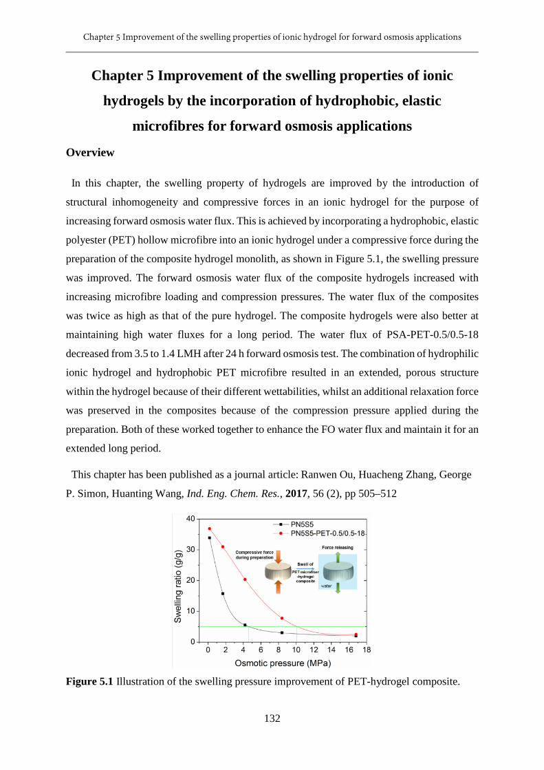
Chapter 5 Improvement of the swelling properties of ionic hydrogel for forward osmosis applications
132
Chapter 5 Improvement of the swelling properties of ionic
hydrogels by the incorporation of hydrophobic, elastic
microfibres for forward osmosis applications
Overview
In this chapter, the swelling property of hydrogels are improved by the introduction of
structural inhomogeneity and compressive forces in an ionic hydrogel for the purpose of
increasing forward osmosis water flux. This is achieved by incorporating a hydrophobic, elastic
polyester (PET) hollow microfibre into an ionic hydrogel under a compressive force during the
preparation of the composite hydrogel monolith, as shown in Figure 5.1, the swelling pressure
was improved. The forward osmosis water flux of the composite hydrogels increased with
increasing microfibre loading and compression pressures. The water flux of the composites
was twice as high as that of the pure hydrogel. The composite hydrogels were also better at
maintaining high water fluxes for a long period. The water flux of PSA-PET-0.5/0.5-18
decreased from 3.5 to 1.4 LMH after 24 h forward osmosis test. The combination of hydrophilic
ionic hydrogel and hydrophobic PET microfibre resulted in an extended, porous structure
within the hydrogel because of their different wettabilities, whilst an additional relaxation force
was preserved in the composites because of the compression pressure applied during the
preparation. Both of these worked together to enhance the FO water flux and maintain it for an
extended long period.
This chapter has been published as a journal article: Ranwen Ou, Huacheng Zhang, George
P. Simon, Huanting Wang, Ind. Eng. Chem. Res., 2017, 56 (2), pp 505–512
Figure 5.1 Illustration of the swelling pressure improvement of PET-hydrogel composite.
Chapter 5 Improvement of the swelling properties of ionic hydrogel for forward osmosis applications
133
5.1 Introduction
One of the most pervasive problems afflicting the world is water scarcity; by 2025, nearly
two-thirds of the world’s population are projected to face water shortage [1]. Tremendous
efforts have been made to search for environmental and cost friendly solutions to this problem.
Among many other technologies, forward osmosis (FO) desalination is gaining growing
attention. Such a process shows great potential to lower the costs of production of fresh water
from saline water because solar energy and other low-grade heat can be directly used [2, 3]. In
the FO process, a semi-permeable membrane is used as the separation medium, and the osmotic
pressure difference on two sides of membrane acts as the driving force. The draw agent
possesses a higher osmotic pressure than the feed solution which determines the performance
of the FO process apart from the FO membrane. A number of materials have been investigated
as draw agents, including salts, polar solvents, saccharide solutions, hydrophilic nanoparticles,
polyelectrolytes and hydrogels [4]. Of the materials studied to date, the stimuli responsive
hydrogel draw agent which was originally reported by our group [2, 3, 5-10], shows great
potential in the forward osmosis application because of the easy recovery of water and easy
regeneration.
The swelling property of hydrogels and the effective contact between FO membrane and
hydrogel are key parameters for achieving high water flux [3, 7, 9]. The degree of contact
between the membrane and hydrogel can be enhanced by decreasing the hydrogel particle size
[9], increasing the softness of hydrogel [3], or in situ preparation of hydrogel monolith on the
FO membrane itself [7]. The swelling properties of hydrogels include the swelling kinetics and
pressure. The swelling kinetics determine the swelling pattern of solvent diffusion and polymer
chain relaxation, while the swelling pressure reveals the driving force of the hydrogel in the
FO process. A simple and useful empirical equation is used to describe the swelling kinetics,
the so called power law [11, 12]:
nt ktMM
=∞
(1)
where Mt and M∞ are the amount of water absorbed at time t and equilibrium, respectively. k
is the characteristic constant of the water-polymer system, and n is the characteristic exponent
of the transport mode. The characteristic exponent n reveals whether the swelling process is a
solvent diffusion controlled or polymer chain relaxation controlled process. The swelling
pressure of polymer hydrogel originates from polymer-water mixing, elastic reaction force of
Chapter 5 Improvement of the swelling properties of ionic hydrogel for forward osmosis applications
134
the network, and the osmotic pressure of ionizable groups. The swelling pressure (П) of an
ionic gel can be expressed as the sum of three contributions from each component [12-14]:
ionelmix ∏+∏+∏=∏ (2)
where Пmix, Пel, and Пion are the mixing, elastic, and ionic contributions, respectively.
The swelling behavior of the hydrogel is strongly dependent on the crosslinking density, and
the interactions between the solvent molecules and the polymeric chain segments [12]. Note
that the swelling property of hydrogel can be modified by changing the crosslinking density
[15], introduction of ionic groups [8] and structural inhomogeneity [16-18]. Firstly, the
crosslinking density plays a major role in determining the absorption properties of hydrogel.
The water molecules cannot be held in a polymer network with a low crosslinking density,
while a highly crosslinked polymer network does not allow the entrance of water. Secondly,
the introduction of ionic groups is good for polymer-water mixing and the mixing of ions with
solvent, and thus the configurational change of gel structure. Consequently, the solvent
diffusion rate and the polymer chain relaxation rate are enhanced accordingly. Thirdly,
introducing structural inhomogeneity such as hydrophilic tunnels or porosity accelerates the
water diffusion in the hydrogel, which improves the polymer-water mixing, and thus enhances
the solvent diffusion rate. In addition, a capillary force can be harnessed if microscale,
connected pores can be generated in the hydrogel, and can act as an additional driving force to
accelerate the solvent diffusion.
In this paper, the swelling properties of hydrogels are modified by the introduction of
structural inhomogeneity and compressive forces in the hydrogel. The structural
inhomogeneity is introduced by addition of a hydrophobic microfibre (made of polyester) into
an ionic hydrogel. The combination of hydrophobic, elastic polyester (PET) microfibre and
hydrophilic hydrogel generates a porous structure, which is expected to be favorable for water
transport. In this study, N-isopropyl acrylamide (NIPAM) and sodium acrylate (SA) were
selected for preparing the hydrophilic hydrogel, while NIPAM offers the hydrogel thermal
responsive ability, and SA endows the hydrogel higher ionic strength. In the preparation
process, the mixture of PET microfibre and monomer solution is compressed during
polymerization, so that part of the compression force due to the deformed fibres can be stored
in the composite. We hypothesize that the addition of PET microfibres in hydrogel changes the
swelling pattern from polymer chain relaxation controlled process to solvent diffusion
controlled process, allowing it to attain a swelling equilibrium much more rapidly. In addition,
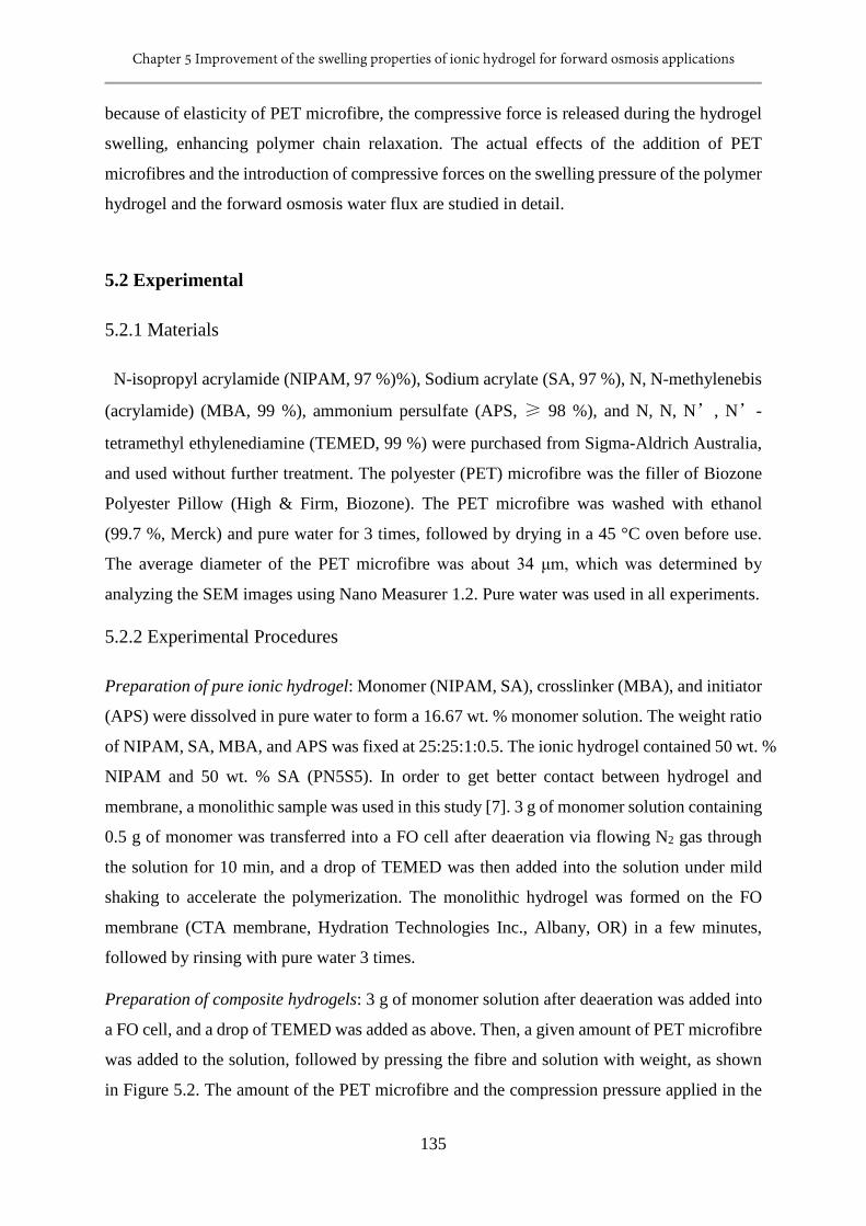
Chapter 5 Improvement of the swelling properties of ionic hydrogel for forward osmosis applications
135
because of elasticity of PET microfibre, the compressive force is released during the hydrogel
swelling, enhancing polymer chain relaxation. The actual effects of the addition of PET
microfibres and the introduction of compressive forces on the swelling pressure of the polymer
hydrogel and the forward osmosis water flux are studied in detail.
5.2 Experimental
5.2.1 Materials
N-isopropyl acrylamide (NIPAM, 97 %)%), Sodium acrylate (SA, 97 %), N, N-methylenebis
(acrylamide) (MBA, 99 %), ammonium persulfate (APS, ≥ 98 %), and N, N, N’, N’-
tetramethyl ethylenediamine (TEMED, 99 %) were purchased from Sigma-Aldrich Australia,
and used without further treatment. The polyester (PET) microfibre was the filler of Biozone
Polyester Pillow (High & Firm, Biozone). The PET microfibre was washed with ethanol
(99.7 %, Merck) and pure water for 3 times, followed by drying in a 45 °C oven before use.
The average diameter of the PET microfibre was about 34 μm, which was determined by
analyzing the SEM images using Nano Measurer 1.2. Pure water was used in all experiments.
5.2.2 Experimental Procedures
Preparation of pure ionic hydrogel: Monomer (NIPAM, SA), crosslinker (MBA), and initiator
(APS) were dissolved in pure water to form a 16.67 wt. % monomer solution. The weight ratio
of NIPAM, SA, MBA, and APS was fixed at 25:25:1:0.5. The ionic hydrogel contained 50 wt. %
NIPAM and 50 wt. % SA (PN5S5). In order to get better contact between hydrogel and
membrane, a monolithic sample was used in this study [7]. 3 g of monomer solution containing
0.5 g of monomer was transferred into a FO cell after deaeration via flowing N2 gas through
the solution for 10 min, and a drop of TEMED was then added into the solution under mild
shaking to accelerate the polymerization. The monolithic hydrogel was formed on the FO
membrane (CTA membrane, Hydration Technologies Inc., Albany, OR) in a few minutes,
followed by rinsing with pure water 3 times.
Preparation of composite hydrogels: 3 g of monomer solution after deaeration was added into
a FO cell, and a drop of TEMED was added as above. Then, a given amount of PET microfibre
was added to the solution, followed by pressing the fibre and solution with weight, as shown
in Figure 5.2. The amount of the PET microfibre and the compression pressure applied in the
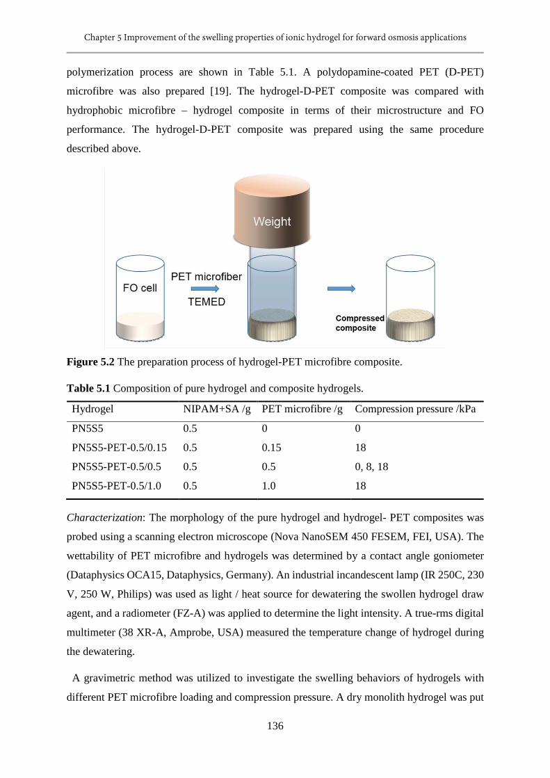
Chapter 5 Improvement of the swelling properties of ionic hydrogel for forward osmosis applications
136
polymerization process are shown in Table 5.1. A polydopamine-coated PET (D-PET)
microfibre was also prepared [19]. The hydrogel-D-PET composite was compared with
hydrophobic microfibre – hydrogel composite in terms of their microstructure and FO
performance. The hydrogel-D-PET composite was prepared using the same procedure
described above.
Figure 5.2 The preparation process of hydrogel-PET microfibre composite.
Table 5.1 Composition of pure hydrogel and composite hydrogels.
Hydrogel NIPAM+SA /g PET microfibre /g Compression pressure /kPa
PN5S5 0.5 0 0
PN5S5-PET-0.5/0.15 0.5 0.15 18
PN5S5-PET-0.5/0.5 0.5 0.5 0, 8, 18
PN5S5-PET-0.5/1.0 0.5 1.0 18
Characterization: The morphology of the pure hydrogel and hydrogel- PET composites was
probed using a scanning electron microscope (Nova NanoSEM 450 FESEM, FEI, USA). The
wettability of PET microfibre and hydrogels was determined by a contact angle goniometer
(Dataphysics OCA15, Dataphysics, Germany). An industrial incandescent lamp (IR 250C, 230
V, 250 W, Philips) was used as light / heat source for dewatering the swollen hydrogel draw
agent, and a radiometer (FZ-A) was applied to determine the light intensity. A true-rms digital
multimeter (38 XR-A, Amprobe, USA) measured the temperature change of hydrogel during
the dewatering.
A gravimetric method was utilized to investigate the swelling behaviors of hydrogels with
different PET microfibre loading and compression pressure. A dry monolith hydrogel was put
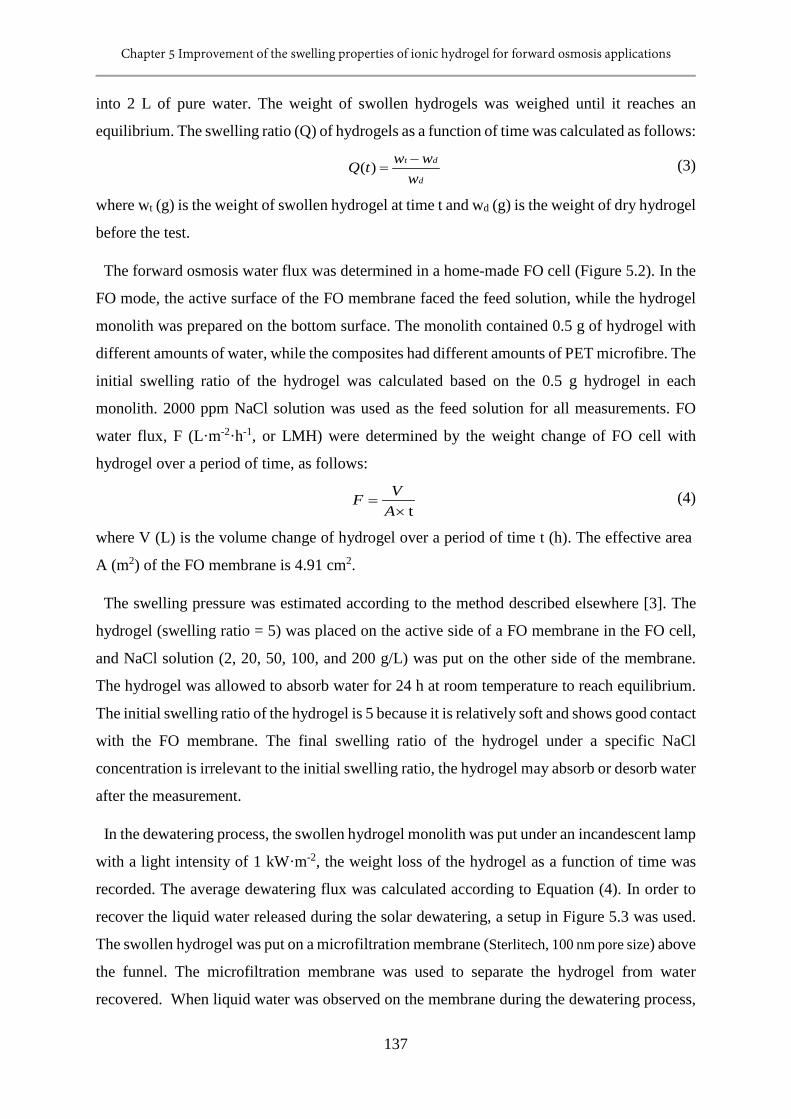
Chapter 5 Improvement of the swelling properties of ionic hydrogel for forward osmosis applications
137
into 2 L of pure water. The weight of swollen hydrogels was weighed until it reaches an
equilibrium. The swelling ratio (Q) of hydrogels as a function of time was calculated as follows:
d
dt
wwwtQ −
=)( (3)
where wt (g) is the weight of swollen hydrogel at time t and wd (g) is the weight of dry hydrogel
before the test.
The forward osmosis water flux was determined in a home-made FO cell (Figure 5.2). In the
FO mode, the active surface of the FO membrane faced the feed solution, while the hydrogel
monolith was prepared on the bottom surface. The monolith contained 0.5 g of hydrogel with
different amounts of water, while the composites had different amounts of PET microfibre. The
initial swelling ratio of the hydrogel was calculated based on the 0.5 g hydrogel in each
monolith. 2000 ppm NaCl solution was used as the feed solution for all measurements. FO
water flux, F (L·m-2·h-1, or LMH) were determined by the weight change of FO cell with
hydrogel over a period of time, as follows:
t×=
AVF (4)
where V (L) is the volume change of hydrogel over a period of time t (h). The effective area
A (m2) of the FO membrane is 4.91 cm2.
The swelling pressure was estimated according to the method described elsewhere [3]. The
hydrogel (swelling ratio = 5) was placed on the active side of a FO membrane in the FO cell,
and NaCl solution (2, 20, 50, 100, and 200 g/L) was put on the other side of the membrane.
The hydrogel was allowed to absorb water for 24 h at room temperature to reach equilibrium.
The initial swelling ratio of the hydrogel is 5 because it is relatively soft and shows good contact
with the FO membrane. The final swelling ratio of the hydrogel under a specific NaCl
concentration is irrelevant to the initial swelling ratio, the hydrogel may absorb or desorb water
after the measurement.
In the dewatering process, the swollen hydrogel monolith was put under an incandescent lamp
with a light intensity of 1 kW·m-2, the weight loss of the hydrogel as a function of time was
recorded. The average dewatering flux was calculated according to Equation (4). In order to
recover the liquid water released during the solar dewatering, a setup in Figure 5.3 was used.
The swollen hydrogel was put on a microfiltration membrane (Sterlitech, 100 nm pore size) above
the funnel. The microfiltration membrane was used to separate the hydrogel from water
recovered. When liquid water was observed on the membrane during the dewatering process,
Chapter 5 Improvement of the swelling properties of ionic hydrogel for forward osmosis applications
138
it was collected by turning on a vacuum pump (140 mL piston syringe pump, Monoject TM)
for a few seconds. The liquid water recovery (Rl, %) was calculated as follows:
100×=wwR l
l (5)
where wl (g) is the weight of liquid water recovered, and w (g) is the total water recovered,
including vapor and liquid.
Figure 5.3 The solar dewatering setup for measuring the liquid water recovery. A
microfiltration membrane (Sterlitech, 100 nm pore size) is applied to block the hydrogel from
water recovered. Vacuum is applied few times when liquid water can be found on membrane
during the dewatering process. A 140 mL piston syringe (Monoject TM) is used to produce a
vacuum inside the filtering flask in order to drive the liquid water into this receptacle.
5.3 Results and Discussion
5.3.1 Morphology of PET-hydrogel composites
The SEM image of PN5S5 hydrogel (Figure 5.4a) shows that the dry monolith hydrogel has
a dense and continuous polymer network structure. Figure 5.4b demonstrates that the PET
microfibre is hollow. The surface and cross-sectional morphology of composite hydrogels are
shown in Figure 5.5. The addition of PET microfibres into NIPAM-SA hydrogel endows the
composite with pores, the composite roughly become more porous with increasing amount of
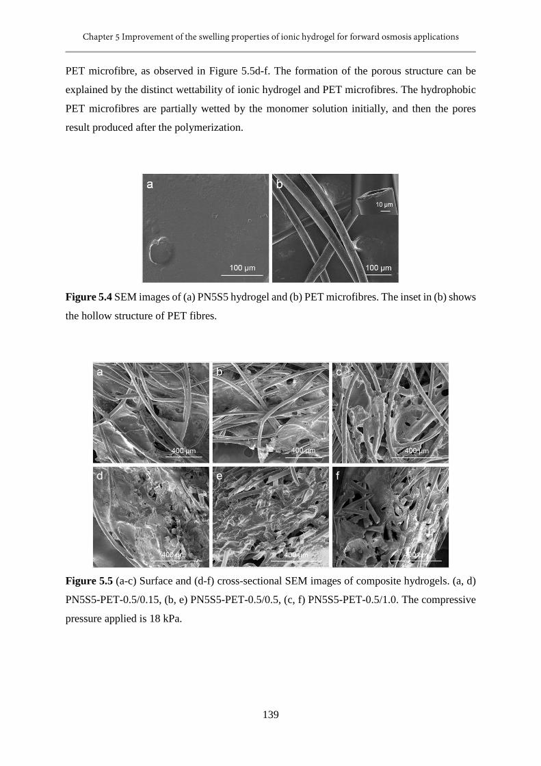
Chapter 5 Improvement of the swelling properties of ionic hydrogel for forward osmosis applications
139
PET microfibre, as observed in Figure 5.5d-f. The formation of the porous structure can be
explained by the distinct wettability of ionic hydrogel and PET microfibres. The hydrophobic
PET microfibres are partially wetted by the monomer solution initially, and then the pores
result produced after the polymerization.
Figure 5.4 SEM images of (a) PN5S5 hydrogel and (b) PET microfibres. The inset in (b) shows
the hollow structure of PET fibres.
Figure 5.5 (a-c) Surface and (d-f) cross-sectional SEM images of composite hydrogels. (a, d)
PN5S5-PET-0.5/0.15, (b, e) PN5S5-PET-0.5/0.5, (c, f) PN5S5-PET-0.5/1.0. The compressive
pressure applied is 18 kPa.
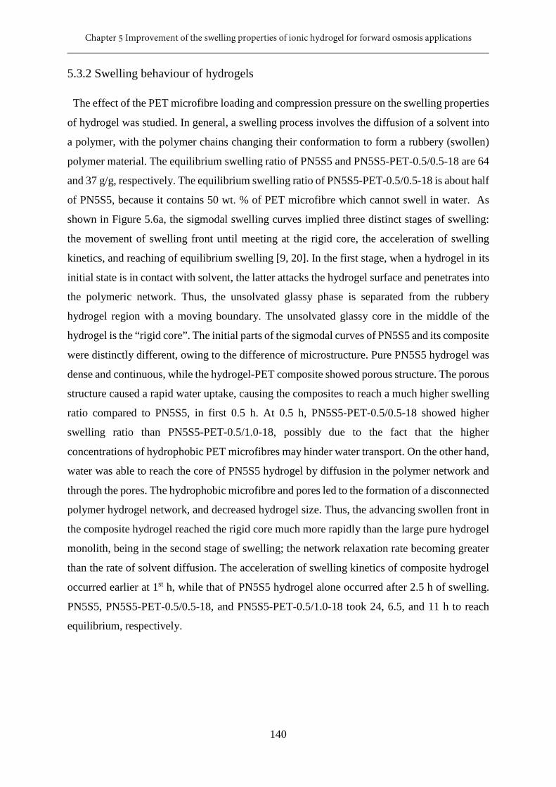
Chapter 5 Improvement of the swelling properties of ionic hydrogel for forward osmosis applications
140
5.3.2 Swelling behaviour of hydrogels
The effect of the PET microfibre loading and compression pressure on the swelling properties
of hydrogel was studied. In general, a swelling process involves the diffusion of a solvent into
a polymer, with the polymer chains changing their conformation to form a rubbery (swollen)
polymer material. The equilibrium swelling ratio of PN5S5 and PN5S5-PET-0.5/0.5-18 are 64
and 37 g/g, respectively. The equilibrium swelling ratio of PN5S5-PET-0.5/0.5-18 is about half
of PN5S5, because it contains 50 wt. % of PET microfibre which cannot swell in water. As
shown in Figure 5.6a, the sigmodal swelling curves implied three distinct stages of swelling:
the movement of swelling front until meeting at the rigid core, the acceleration of swelling
kinetics, and reaching of equilibrium swelling [9, 20]. In the first stage, when a hydrogel in its
initial state is in contact with solvent, the latter attacks the hydrogel surface and penetrates into
the polymeric network. Thus, the unsolvated glassy phase is separated from the rubbery
hydrogel region with a moving boundary. The unsolvated glassy core in the middle of the
hydrogel is the “rigid core”. The initial parts of the sigmodal curves of PN5S5 and its composite
were distinctly different, owing to the difference of microstructure. Pure PN5S5 hydrogel was
dense and continuous, while the hydrogel-PET composite showed porous structure. The porous
structure caused a rapid water uptake, causing the composites to reach a much higher swelling
ratio compared to PN5S5, in first 0.5 h. At 0.5 h, PN5S5-PET-0.5/0.5-18 showed higher
swelling ratio than PN5S5-PET-0.5/1.0-18, possibly due to the fact that the higher
concentrations of hydrophobic PET microfibres may hinder water transport. On the other hand,
water was able to reach the core of PN5S5 hydrogel by diffusion in the polymer network and
through the pores. The hydrophobic microfibre and pores led to the formation of a disconnected
polymer hydrogel network, and decreased hydrogel size. Thus, the advancing swollen front in
the composite hydrogel reached the rigid core much more rapidly than the large pure hydrogel
monolith, being in the second stage of swelling; the network relaxation rate becoming greater
than the rate of solvent diffusion. The acceleration of swelling kinetics of composite hydrogel
occurred earlier at 1st h, while that of PN5S5 hydrogel alone occurred after 2.5 h of swelling.
PN5S5, PN5S5-PET-0.5/0.5-18, and PN5S5-PET-0.5/1.0-18 took 24, 6.5, and 11 h to reach
equilibrium, respectively.
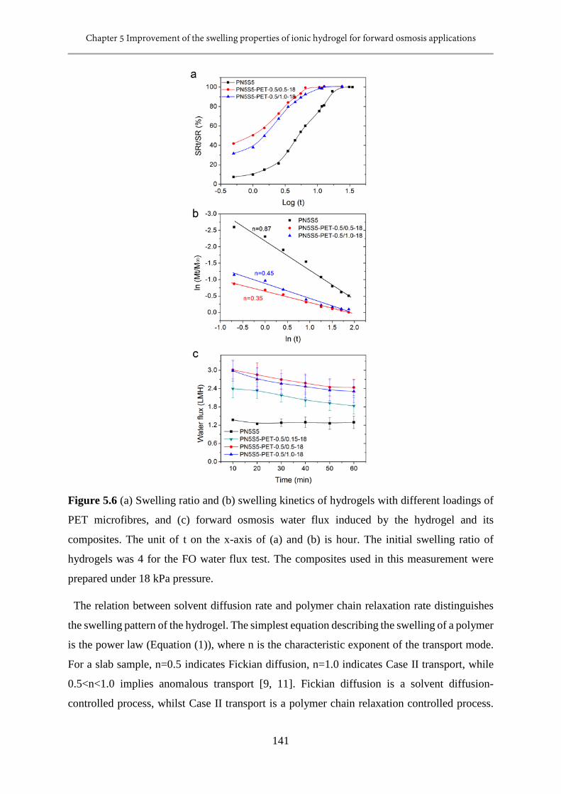
Chapter 5 Improvement of the swelling properties of ionic hydrogel for forward osmosis applications
141
Figure 5.6 (a) Swelling ratio and (b) swelling kinetics of hydrogels with different loadings of
PET microfibres, and (c) forward osmosis water flux induced by the hydrogel and its
composites. The unit of t on the x-axis of (a) and (b) is hour. The initial swelling ratio of
hydrogels was 4 for the FO water flux test. The composites used in this measurement were
prepared under 18 kPa pressure.
The relation between solvent diffusion rate and polymer chain relaxation rate distinguishes
the swelling pattern of the hydrogel. The simplest equation describing the swelling of a polymer
is the power law (Equation (1)), where n is the characteristic exponent of the transport mode.
For a slab sample, n=0.5 indicates Fickian diffusion, n=1.0 indicates Case II transport, while
0.5<n<1.0 implies anomalous transport [9, 11]. Fickian diffusion is a solvent diffusion-
controlled process, whilst Case II transport is a polymer chain relaxation controlled process.
Chapter 5 Improvement of the swelling properties of ionic hydrogel for forward osmosis applications
142
However, when the water penetration rate is much smaller than the polymer chain relaxation
rate, it is possible to achieve n values less than 0.5, which is still regarded as Fickian diffusion,
but known as “Less Fickian” behavior [21]. As shown in Figure 5.6b, n=0.87 means that the
swelling of PN5S5 in water is mainly controlled by the polymer chain relaxation. After
blending with PET microfibre, the values of n for PN5S5-PET-0.5/0.5-18 and PN5S5-PET-
0.5/1.0-18 decrease to 0.45 and 0.35, respectively. These n values are lower than 0.5, which
means that the swelling of composite hydrogels exhibit Less Fickian diffusion, and that the
polymer chain relaxation rate is much faster than the solvent diffusion rate. This is caused by
the porous structure of composite and the decreased hydrogel size, and thus the acceleration of
swelling kinetics. Figure 5.6c shows the forward osmosis water flux of hydrogels, the
composite hydrogel showed higher water flux than the pure one, while PN5S5-PET-0.5/0.5-18
performed best, which was about twice as high as that of PN5S5. The FO water flux of
hydrogels is well consistent with the swelling kinetics.
As shown in Figure 5.7, the strips of PN5S5 and PN5S5-PET-0.5/0.5 were put vertically on
rhodamine B aqueous solution to observe the swelling process. After 2 min, the height of RhB
solution in the composite was 6.5 times as high as that of PN5S5. This confirms that the porous
structure generated by addition of PET microfibre provides an extra driving force for the water
absorption.
Figure 5.7 The optical images of pure PN5S5 hydrogel and PN5S5-PET-0.5/0.5 composite
hydrogel (a) before and (b) after swelling in aqueous rhodamine B (RhB) solution. The image
(b) was taken after 2 mins of absorption.
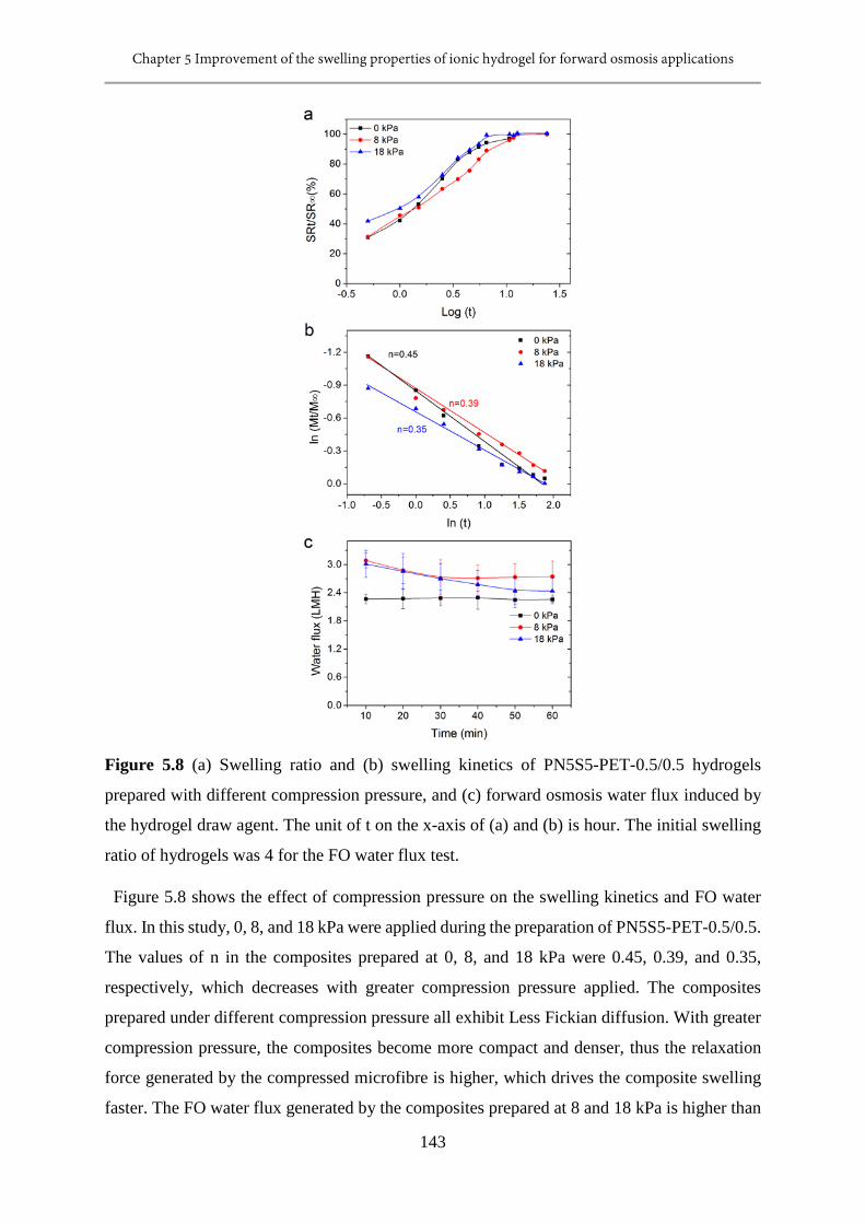
Chapter 5 Improvement of the swelling properties of ionic hydrogel for forward osmosis applications
143
Figure 5.8 (a) Swelling ratio and (b) swelling kinetics of PN5S5-PET-0.5/0.5 hydrogels
prepared with different compression pressure, and (c) forward osmosis water flux induced by
the hydrogel draw agent. The unit of t on the x-axis of (a) and (b) is hour. The initial swelling
ratio of hydrogels was 4 for the FO water flux test.
Figure 5.8 shows the effect of compression pressure on the swelling kinetics and FO water
flux. In this study, 0, 8, and 18 kPa were applied during the preparation of PN5S5-PET-0.5/0.5.
The values of n in the composites prepared at 0, 8, and 18 kPa were 0.45, 0.39, and 0.35,
respectively, which decreases with greater compression pressure applied. The composites
prepared under different compression pressure all exhibit Less Fickian diffusion. With greater
compression pressure, the composites become more compact and denser, thus the relaxation
force generated by the compressed microfibre is higher, which drives the composite swelling
faster. The FO water flux generated by the composites prepared at 8 and 18 kPa is higher than
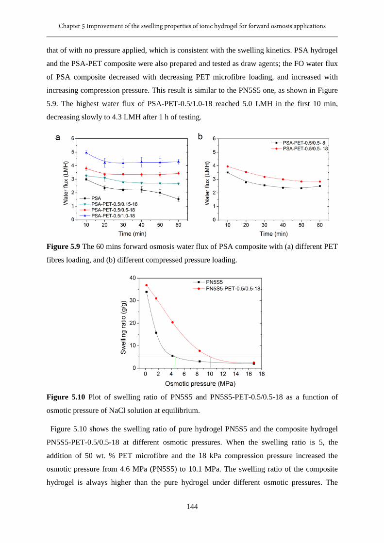
Chapter 5 Improvement of the swelling properties of ionic hydrogel for forward osmosis applications
144
that of with no pressure applied, which is consistent with the swelling kinetics. PSA hydrogel
and the PSA-PET composite were also prepared and tested as draw agents; the FO water flux
of PSA composite decreased with decreasing PET microfibre loading, and increased with
increasing compression pressure. This result is similar to the PN5S5 one, as shown in Figure
5.9. The highest water flux of PSA-PET-0.5/1.0-18 reached 5.0 LMH in the first 10 min,
decreasing slowly to 4.3 LMH after 1 h of testing.
Figure 5.9 The 60 mins forward osmosis water flux of PSA composite with (a) different PET
fibres loading, and (b) different compressed pressure loading.
Figure 5.10 Plot of swelling ratio of PN5S5 and PN5S5-PET-0.5/0.5-18 as a function of
osmotic pressure of NaCl solution at equilibrium.
Figure 5.10 shows the swelling ratio of pure hydrogel PN5S5 and the composite hydrogel
PN5S5-PET-0.5/0.5-18 at different osmotic pressures. When the swelling ratio is 5, the
addition of 50 wt. % PET microfibre and the 18 kPa compression pressure increased the
osmotic pressure from 4.6 MPa (PN5S5) to 10.1 MPa. The swelling ratio of the composite
hydrogel is always higher than the pure hydrogel under different osmotic pressures. The
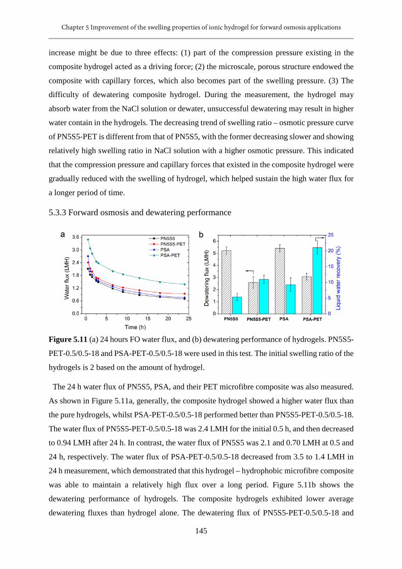
Chapter 5 Improvement of the swelling properties of ionic hydrogel for forward osmosis applications
145
increase might be due to three effects: (1) part of the compression pressure existing in the
composite hydrogel acted as a driving force; (2) the microscale, porous structure endowed the
composite with capillary forces, which also becomes part of the swelling pressure. (3) The
difficulty of dewatering composite hydrogel. During the measurement, the hydrogel may
absorb water from the NaCl solution or dewater, unsuccessful dewatering may result in higher
water contain in the hydrogels. The decreasing trend of swelling ratio – osmotic pressure curve
of PN5S5-PET is different from that of PN5S5, with the former decreasing slower and showing
relatively high swelling ratio in NaCl solution with a higher osmotic pressure. This indicated
that the compression pressure and capillary forces that existed in the composite hydrogel were
gradually reduced with the swelling of hydrogel, which helped sustain the high water flux for
a longer period of time.
5.3.3 Forward osmosis and dewatering performance
Figure 5.11 (a) 24 hours FO water flux, and (b) dewatering performance of hydrogels. PN5S5-
PET-0.5/0.5-18 and PSA-PET-0.5/0.5-18 were used in this test. The initial swelling ratio of the
hydrogels is 2 based on the amount of hydrogel.
The 24 h water flux of PN5S5, PSA, and their PET microfibre composite was also measured.
As shown in Figure 5.11a, generally, the composite hydrogel showed a higher water flux than
the pure hydrogels, whilst PSA-PET-0.5/0.5-18 performed better than PN5S5-PET-0.5/0.5-18.
The water flux of PN5S5-PET-0.5/0.5-18 was 2.4 LMH for the initial 0.5 h, and then decreased
to 0.94 LMH after 24 h. In contrast, the water flux of PN5S5 was 2.1 and 0.70 LMH at 0.5 and
24 h, respectively. The water flux of PSA-PET-0.5/0.5-18 decreased from 3.5 to 1.4 LMH in
24 h measurement, which demonstrated that this hydrogel – hydrophobic microfibre composite
was able to maintain a relatively high flux over a long period. Figure 5.11b shows the
dewatering performance of hydrogels. The composite hydrogels exhibited lower average
dewatering fluxes than hydrogel alone. The dewatering flux of PN5S5-PET-0.5/0.5-18 and
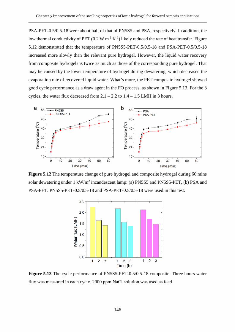
Chapter 5 Improvement of the swelling properties of ionic hydrogel for forward osmosis applications
146
PSA-PET-0.5/0.5-18 were about half of that of PN5S5 and PSA, respectively. In addition, the
low thermal conductivity of PET (0.2 W m-1 K-1) likely reduced the rate of heat transfer. Figure
5.12 demonstrated that the temperature of PN5S5-PET-0.5/0.5-18 and PSA-PET-0.5/0.5-18
increased more slowly than the relevant pure hydrogel. However, the liquid water recovery
from composite hydrogels is twice as much as those of the corresponding pure hydrogel. That
may be caused by the lower temperature of hydrogel during dewatering, which decreased the
evaporation rate of recovered liquid water. What’s more, the PET composite hydrogel showed
good cycle performance as a draw agent in the FO process, as shown in Figure 5.13. For the 3
cycles, the water flux decreased from 2.1 – 2.2 to 1.4 – 1.5 LMH in 3 hours.
Figure 5.12 The temperature change of pure hydrogel and composite hydrogel during 60 mins
solar dewatering under 1 kW/m2 incandescent lamp: (a) PN5S5 and PN5S5-PET, (b) PSA and
PSA-PET. PN5S5-PET-0.5/0.5-18 and PSA-PET-0.5/0.5-18 were used in this test.
Figure 5.13 The cycle performance of PN5S5-PET-0.5/0.5-18 composite. Three hours water
flux was measured in each cycle. 2000 ppm NaCl solution was used as feed.
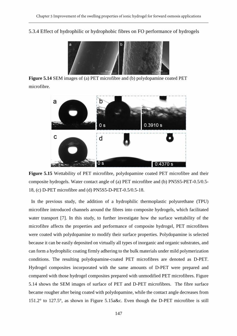
Chapter 5 Improvement of the swelling properties of ionic hydrogel for forward osmosis applications
147
5.3.4 Effect of hydrophilic or hydrophobic fibres on FO performance of hydrogels
Figure 5.14 SEM images of (a) PET microfibre and (b) polydopamine coated PET
microfibre.
Figure 5.15 Wettability of PET microfibre, polydopamine coated PET microfibre and their
composite hydrogels. Water contact angle of (a) PET microfibre and (b) PN5S5-PET-0.5/0.5-
18, (c) D-PET microfibre and (d) PN5S5-D-PET-0.5/0.5-18.
In the previous study, the addition of a hydrophilic thermoplastic polyurethane (TPU)
microfibre introduced channels around the fibres into composite hydrogels, which facilitated
water transport [7]. In this study, to further investigate how the surface wettability of the
microfibre affects the properties and performance of composite hydrogel, PET microfibres
were coated with polydopamine to modify their surface properties. Polydopamine is selected
because it can be easily deposited on virtually all types of inorganic and organic substrates, and
can form a hydrophilic coating firmly adhering to the bulk materials under mild polymerization
conditions. The resulting polydopamine-coated PET microfibres are denoted as D-PET.
Hydrogel composites incorporated with the same amounts of D-PET were prepared and
compared with those hydrogel composites prepared with unmodified PET microfibres. Figure
5.14 shows the SEM images of surface of PET and D-PET microfibres. The fibre surface
became rougher after being coated with polydopamine, while the contact angle decreases from
151.2° to 127.5°, as shown in Figure 5.15a&c. Even though the D-PET microfibre is still
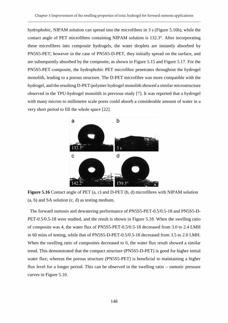
Chapter 5 Improvement of the swelling properties of ionic hydrogel for forward osmosis applications
148
hydrophobic, NIPAM solution can spread into the microfibres in 3 s (Figure 5.16b), while the
contact angle of PET microfibres containing NIPAM solution is 132.3°. After incorporating
these microfibres into composite hydrogels, the water droplets are instantly absorbed by
PN5S5-PET; however in the case of PN5S5-D-PET, they initially spread on the surface, and
are subsequently absorbed by the composite, as shown in Figure 5.15 and Figure 5.17. For the
PN5S5-PET composite, the hydrophobic PET microfibre penetrates throughout the hydrogel
monolith, leading to a porous structure. The D-PET microfibre was more compatible with the
hydrogel, and the resulting D-PET/polymer hydrogel monolith showed a similar microstructure
observed in the TPU-hydrogel monolith in previous study [7]. It was reported that a hydrogel
with many micron to millimetre scale pores could absorb a considerable amount of water in a
very short period to fill the whole space [22].
Figure 5.16 Contact angle of PET (a, c) and D-PET (b, d) microfibres with NIPAM solution
(a, b) and SA solution (c, d) as testing medium.
The forward osmosis and dewatering performance of PN5S5-PET-0.5/0.5-18 and PN5S5-D-
PET-0.5/0.5-18 were studied, and the result is shown in Figure 5.18. When the swelling ratio
of composite was 4, the water flux of PN5S5-PET-0.5/0.5-18 decreased from 3.0 to 2.4 LMH
in 60 mins of testing, while that of PN5S5-D-PET-0.5/0.5-18 decreased from 3.5 to 2.0 LMH.
When the swelling ratio of composites decreased to 0, the water flux result showed a similar
trend. This demonstrated that the compact structure (PN5S5-D-PET) is good for higher initial
water flux; whereas the porous structure (PN5S5-PET) is beneficial to maintaining a higher
flux level for a longer period. This can be observed in the swelling ratio – osmotic pressure
curves in Figure 5.10.
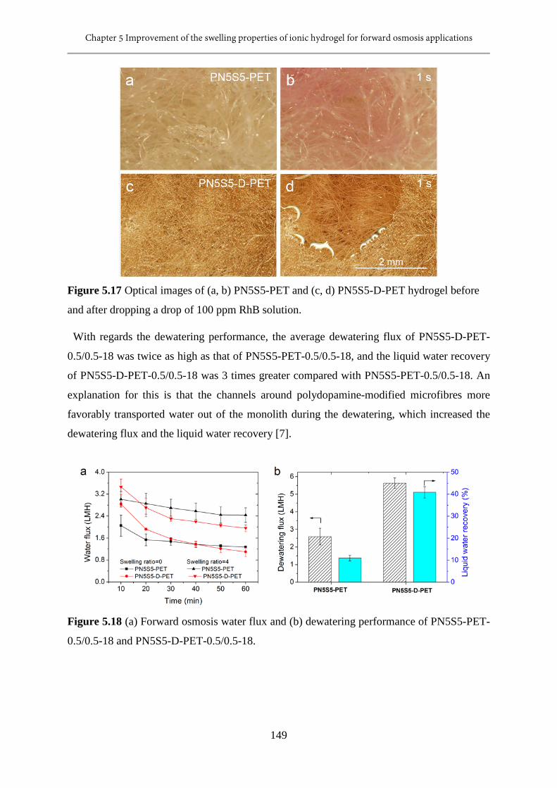
Chapter 5 Improvement of the swelling properties of ionic hydrogel for forward osmosis applications
149
Figure 5.17 Optical images of (a, b) PN5S5-PET and (c, d) PN5S5-D-PET hydrogel before
and after dropping a drop of 100 ppm RhB solution.
With regards the dewatering performance, the average dewatering flux of PN5S5-D-PET-
0.5/0.5-18 was twice as high as that of PN5S5-PET-0.5/0.5-18, and the liquid water recovery
of PN5S5-D-PET-0.5/0.5-18 was 3 times greater compared with PN5S5-PET-0.5/0.5-18. An
explanation for this is that the channels around polydopamine-modified microfibres more
favorably transported water out of the monolith during the dewatering, which increased the
dewatering flux and the liquid water recovery [7].
Figure 5.18 (a) Forward osmosis water flux and (b) dewatering performance of PN5S5-PET-
0.5/0.5-18 and PN5S5-D-PET-0.5/0.5-18.
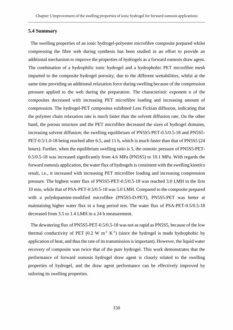
Chapter 5 Improvement of the swelling properties of ionic hydrogel for forward osmosis applications
150
5.4 Summary
The swelling properties of an ionic hydrogel-polyester microfibre composite prepared whilst
compressing the fibre web during synthesis has been studied in an effort to provide an
additional mechanism to improve the properties of hydrogels as a forward osmosis draw agent.
The combination of a hydrophilic ionic hydrogel and a hydrophobic PET microfibre mesh
imparted to the composite hydrogel porosity, due to the different wettabilities, whilst at the
same time providing an additional relaxation force during swelling because of the compression
pressure applied to the web during the preparation. The characteristic exponent n of the
composites decreased with increasing PET microfibre loading and increasing amount of
compression. The hydrogel-PET composites exhibited Less Fickian diffusion, indicating that
the polymer chain relaxation rate is much faster than the solvent diffusion rate. On the other
hand, the porous structure and the PET microfibre decreased the sizes of hydrogel domains,
increasing solvent diffusion; the swelling equilibrium of PN5S5-PET-0.5/0.5-18 and PN5S5-
PET-0.5/1.0-18 being reached after 6.5, and 11 h, which is much faster than that of PN5S5 (24
hours). Further, when the equilibrium swelling ratio is 5, the osmotic pressure of PN5S5-PET-
0.5/0.5-18 was increased significantly from 4.6 MPa (PN5S5) to 10.1 MPa. With regards the
forward osmosis application, the water flux of hydrogels is consistent with the swelling kinetics
result, i.e., it increased with increasing PET microfibre loading and increasing compression
pressure. The highest water flux of PN5S5-PET-0.5/0.5-18 was reached 3.0 LMH in the first
10 min, while that of PSA-PET-0.5/0.5-18 was 5.0 LMH. Compared to the composite prepared
with a polydopamine-modified microfibre (PN5S5-D-PET), PN5S5-PET was better at
maintaining higher water flux in a long period test. The water flux of PSA-PET-0.5/0.5-18
decreased from 3.5 to 1.4 LMH in a 24 h measurement.
The dewatering flux of PN5S5-PET-0.5/0.5-18 was not as rapid as PN5S5, because of the low
thermal conductivity of PET (0.2 W m-1 K-1) (since the hydrogel is made hydrophobic by
application of heat, and thus the rate of its transmission is important). However, the liquid water
recovery of composite was twice that of the pure hydrogel. This work demonstrates that the
performance of forward osmosis hydrogel draw agent is closely related to the swelling
properties of hydrogel, and the draw agent performance can be effectively improved by
tailoring its swelling properties.
Chapter 5 Improvement of the swelling properties of ionic hydrogel for forward osmosis applications
151
5.5 References
[1] M. Elimelech, W.A. Phillip, The future of seawater desalination: energy, technology, and
the environment, science, 333 (2011) 712-717.
[2] A. Razmjou, M.R. Barati, G.P. Simon, K. Suzuki, H. Wang, Fast deswelling of
nanocomposite polymer hydrogels via magnetic field-induced heating for emerging FO
desalination, Environmental science & technology, 47 (2013) 6297-6305.
[3] Y. Zeng, L. Qiu, K. Wang, J. Yao, D. Li, G.P. Simon, R. Wang, H. Wang, Significantly
enhanced water flux in forward osmosis desalination with polymer-graphene composite
hydrogels as a draw agent, Rsc Advances, 3 (2013) 887-894.
[4] R. Ou, Y. Wang, H. Wang, T. Xu, Thermo-sensitive polyelectrolytes as draw solutions in
forward osmosis process, Desalination, 318 (2013) 48-55.
[5] D. Li, X. Zhang, J. Yao, G.P. Simon, H. Wang, Stimuli-responsive polymer hydrogels as
a new class of draw agent for forward osmosis desalination, Chemical Communications, 47
(2011) 1710-1712.
[6] D. Li, X. Zhang, J. Yao, Y. Zeng, G.P. Simon, H. Wang, Composite polymer hydrogels as
draw agents in forward osmosis and solar dewatering, Soft Matter, 7 (2011) 10048-10056.
[7] R. Ou, H. Zhang, G.P. Simon, H. Wang, Microfiber-polymer hydrogel monolith as
forward osmosis draw agent, Journal of Membrane Science, 510 (2016) 426-436.
[8] A. Razmjou, Q. Liu, G.P. Simon, H. Wang, Bifunctional polymer hydrogel layers as
forward osmosis draw agents for continuous production of fresh water using solar energy,
Environmental science & technology, 47 (2013) 13160-13166.
[9] A. Razmjou, G.P. Simon, H. Wang, Effect of particle size on the performance of forward
osmosis desalination by stimuli-responsive polymer hydrogels as a draw agent, Chemical
engineering journal, 215 (2013) 913-920.
[10] J. Wei, Z.-X. Low, R. Ou, G.P. Simon, H. Wang, Hydrogel-polyurethane
interpenetrating network material as an advanced draw agent for forward osmosis process,
Water Research, 96 (2016) 292-298.
[11] F. Ganji, S. Vasheghani-Farahani, E. Vasheghani-Farahani, Theoretical description of
hydrogel swelling: a review, Iran Polym J, 19 (2010) 375-398.
[12] M. Grassi, G. Grassi, Mathematical modelling and controlled drug delivery: matrix
systems, Current drug delivery, 2 (2005) 97-116.
[13] E. Vasheghani-Farahani, J.H. Vera, D.G. Cooper, M.E. Weber, Swelling of ionic gels in
electrolyte solutions, Industrial & engineering chemistry research, 29 (1990) 554-560.
Chapter 5 Improvement of the swelling properties of ionic hydrogel for forward osmosis applications
152
[14] H. Wang, J. Wei, G.P. Simon, Response to osmotic pressure versus swelling pressure:
comment on “bifunctional polymer hydrogel layers as forward osmosis draw agents for
continuous production of fresh water using solar energy”, Environmental science &
technology, 48 (2014) 4214-4215.
[15] W.A. Laftah, S. Hashim, A.N. Ibrahim, Polymer hydrogels: A review, Polymer-Plastics
Technology and Engineering, 50 (2011) 1475-1486.
[16] H. Cong, L. Li, S. Zheng, Poly (N-isopropylacrylamide)-block-poly (vinyl pyrrolidone)
block copolymer networks: Synthesis and rapid thermoresponse of hydrogels, Polymer, 54
(2013) 1370-1380.
[17] L.-W. Xia, R. Xie, X.-J. Ju, W. Wang, Q. Chen, L.-Y. Chu, Nano-structured smart
hydrogels with rapid response and high elasticity, Nature communications, 4 (2013).
[18] X.-Z. Zhang, Y.-Y. Yang, T.-S. Chung, K.-X. Ma, Preparation and characterization of
fast response macroporous poly (N-isopropylacrylamide) hydrogels, Langmuir, 17 (2001)
6094-6099.
[19] H. Lee, S.M. Dellatore, W.M. Miller, P.B. Messersmith, Mussel-inspired surface
chemistry for multifunctional coatings, science, 318 (2007) 426-430.
[20] G. Gerlach, K.-F. Arndt, Hydrogel sensors and actuators: engineering and technology,
Springer Science & Business Media, 2009.
[21] J. Wang, W. Wu, Z. Lin, Kinetics and thermodynamics of the water sorption of 2‐
hydroxyethyl methacrylate/styrene copolymer hydrogels, Journal of applied polymer science,
109 (2008) 3018-3023.
[22] H. Omidian, J.G. Rocca, K. Park, Elastic, superporous hydrogel hybrids of
polyacrylamide and sodium alginate, Macromolecular bioscience, 6 (2006) 703-710.
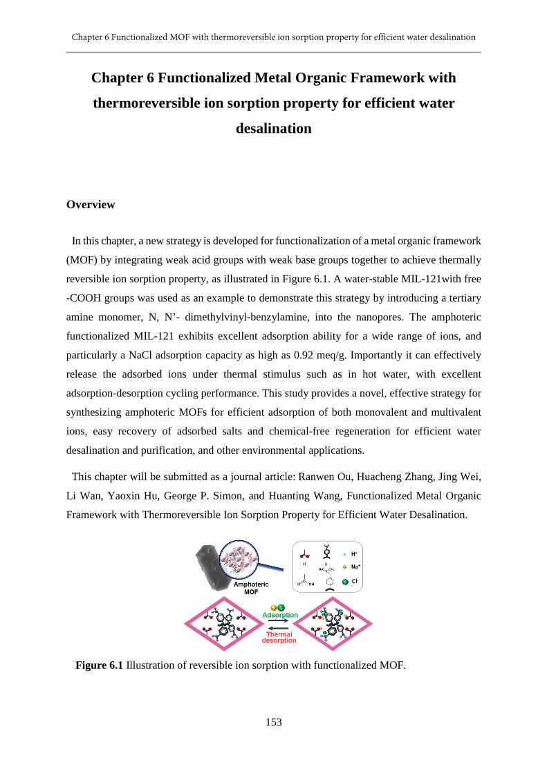
Chapter 6 Functionalized MOF with thermoreversible ion sorption property for efficient water desalination
153
Chapter 6 Functionalized Metal Organic Framework with
thermoreversible ion sorption property for efficient water
desalination
Overview
In this chapter, a new strategy is developed for functionalization of a metal organic framework
(MOF) by integrating weak acid groups with weak base groups together to achieve thermally
reversible ion sorption property, as illustrated in Figure 6.1. A water-stable MIL-121with free
-COOH groups was used as an example to demonstrate this strategy by introducing a tertiary
amine monomer, N, N’- dimethylvinyl-benzylamine, into the nanopores. The amphoteric
functionalized MIL-121 exhibits excellent adsorption ability for a wide range of ions, and
particularly a NaCl adsorption capacity as high as 0.92 meq/g. Importantly it can effectively
release the adsorbed ions under thermal stimulus such as in hot water, with excellent
adsorption-desorption cycling performance. This study provides a novel, effective strategy for
synthesizing amphoteric MOFs for efficient adsorption of both monovalent and multivalent
ions, easy recovery of adsorbed salts and chemical-free regeneration for efficient water
desalination and purification, and other environmental applications.
This chapter will be submitted as a journal article: Ranwen Ou, Huacheng Zhang, Jing Wei,
Li Wan, Yaoxin Hu, George P. Simon, and Huanting Wang, Functionalized Metal Organic
Framework with Thermoreversible Ion Sorption Property for Efficient Water Desalination.
Figure 6.1 Illustration of reversible ion sorption with functionalized MOF.
Chapter 6 Functionalized MOF with thermoreversible ion sorption property for efficient water desalination
154
6.1 Introduction
Metal organic frameworks (MOFs) are a class of porous materials built from organic linkers
and inorganic metal nodes or metal-based clusters through coordination bonds, and are well
known for high surface area, uniform pore size, controllable structures, and readily tailorable
functions.[1-5] Among a large variety of MOFs, stimuli-responsive MOFs have attracted
increasing attention because of their attractive structures and properties that can change to adapt
surrounding environment.[6-9] The introduction of responsive ability endows MOFs with
unique functionalities and properties for many potential applications such as controllable
adsorption and separation, energy storage and clean energy, sensing and catalysis. [6, 10-13]
Therefore, developing stimuli-responsive MOFs and leveraging their properties for novel
applications are of great significance.
Ion adsorption has been widely used in many areas such as water desalination and purification,
catalysis, food processing, and pharmaceutical industries.[14-16] To date, porous solid
materials such as activated carbons, metal oxides, zeolites, clays, and metal organic
frameworks have been used as adsorbents for ion removal in various processes.[17] In
particular, highly porous and flexible MOFs have been traditionally focused on gas adsorption
and storage; only until recently, they been explored for adsorbing cations and anions in liquid
phase, which is very promising for separation of molecules and ions.[18-22] Importantly, their
diverse framework structure and high surface area show potential advantages in achieving
superior ion adsorption kinetics and capacity.[23-28] Until now, the MOFs have been shown
to have good properties for adsorbing metal pollutants in oxo-hydroxo anion forms such as
perchlorate, chromate, selenite and arsenate in water treatment and purification processes; but
they are not effective in adsorbing monovalent metal salts such as NaCl, which are commonly
contained in seawater and other saline waters. Furthermore, the regeneration of spent MOFs
usually requires the use of chemicals via ion exchange process, which is costly and
environmentally unfriendly. Therefore, it is highly desirable to synthesize MOF adsorbents that
can efficiently adsorb various ions including monovalent ions and can be regenerated without
involving chemicals; it is anticipated that such new adsorbents would represent a major
technological advance in the development of functional MOFs for a green and low-energy
process for water desalination and purification to address worldwide shortage of fresh drinking
water.[29, 30]
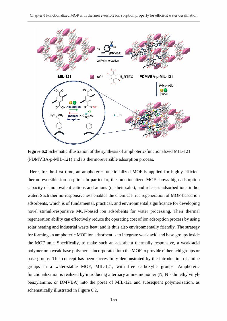
Chapter 6 Functionalized MOF with thermoreversible ion sorption property for efficient water desalination
155
Figure 6.2 Schematic illustration of the synthesis of amphoteric-functionalized MIL-121
(PDMVBA-p-MIL-121) and its thermoreversible adsorption process.
Here, for the first time, an amphoteric functionalized MOF is applied for highly efficient
thermoreversible ion sorption. In particular, the functionalized MOF shows high adsorption
capacity of monovalent cations and anions (or their salts), and releases adsorbed ions in hot
water. Such thermo-responsiveness enables the chemical-free regeneration of MOF-based ion
adsorbents, which is of fundamental, practical, and environmental significance for developing
novel stimuli-responsive MOF-based ion adsorbents for water processing. Their thermal
regeneration ability can effectively reduce the operating cost of ion adsorption process by using
solar heating and industrial waste heat, and is thus also environmentally friendly. The strategy
for forming an amphoteric MOF ion adsorbent is to integrate weak acid and base groups inside
the MOF unit. Specifically, to make such an adsorbent thermally responsive, a weak-acid
polymer or a weak-base polymer is incorporated into the MOF to provide either acid groups or
base groups. This concept has been successfully demonstrated by the introduction of amine
groups in a water-stable MOF, MIL-121, with free carboxylic groups. Amphoteric
functionalization is realized by introducing a tertiary amine monomer (N, N’- dimethylvinyl-
benzylamine, or DMVBA) into the pores of MIL-121 and subsequent polymerization, as
schematically illustrated in Figure 6.2.
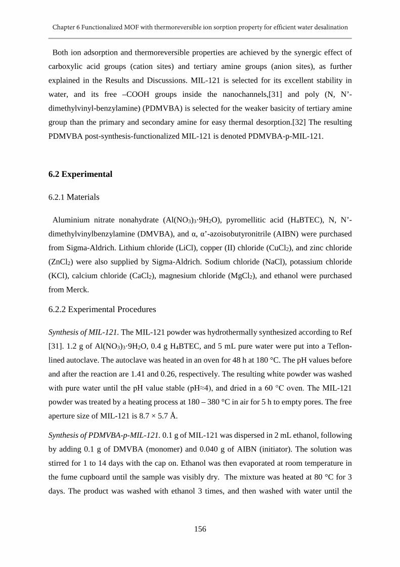
Chapter 6 Functionalized MOF with thermoreversible ion sorption property for efficient water desalination
156
Both ion adsorption and thermoreversible properties are achieved by the synergic effect of
carboxylic acid groups (cation sites) and tertiary amine groups (anion sites), as further
explained in the Results and Discussions. MIL-121 is selected for its excellent stability in
water, and its free –COOH groups inside the nanochannels,[31] and poly (N, N’-
dimethylvinyl-benzylamine) (PDMVBA) is selected for the weaker basicity of tertiary amine
group than the primary and secondary amine for easy thermal desorption.[32] The resulting
PDMVBA post-synthesis-functionalized MIL-121 is denoted PDMVBA-p-MIL-121.
6.2 Experimental
6.2.1 Materials
Aluminium nitrate nonahydrate (Al(NO3)3·9H2O), pyromellitic acid (H4BTEC), N, N’-
dimethylvinylbenzylamine (DMVBA), and α, α’-azoisobutyronitrile (AIBN) were purchased
from Sigma-Aldrich. Lithium chloride (LiCl), copper (II) chloride (CuCl2), and zinc chloride
(ZnCl2) were also supplied by Sigma-Aldrich. Sodium chloride (NaCl), potassium chloride
(KCl), calcium chloride (CaCl2), magnesium chloride (MgCl2), and ethanol were purchased
from Merck.
6.2.2 Experimental Procedures
Synthesis of MIL-121. The MIL-121 powder was hydrothermally synthesized according to Ref
[31]. 1.2 g of Al(NO3)3·9H2O, 0.4 g H4BTEC, and 5 mL pure water were put into a Teflon-
lined autoclave. The autoclave was heated in an oven for 48 h at 180 °C. The pH values before
and after the reaction are 1.41 and 0.26, respectively. The resulting white powder was washed
with pure water until the pH value stable (pH≈4), and dried in a 60 °C oven. The MIL-121
powder was treated by a heating process at 180 – 380 °C in air for 5 h to empty pores. The free
aperture size of MIL-121 is 8.7 × 5.7 Å.
Synthesis of PDMVBA-p-MIL-121. 0.1 g of MIL-121 was dispersed in 2 mL ethanol, following
by adding 0.1 g of DMVBA (monomer) and 0.040 g of AIBN (initiator). The solution was
stirred for 1 to 14 days with the cap on. Ethanol was then evaporated at room temperature in
the fume cupboard until the sample was visibly dry. The mixture was heated at 80 °C for 3
days. The product was washed with ethanol 3 times, and then washed with water until the
Chapter 6 Functionalized MOF with thermoreversible ion sorption property for efficient water desalination
157
conductivity of supernatant was less than 5 μS/cm. The resultant PDMVBA-p-MIL-121 was
dried, ground and used for characterization.
Characterization. The X-ray diffraction (XRD) patterns were determined by a Rigaku Miniflex
600 X-ray diffractometer at 40 kV and 25 mA at a scanning rate of 2 °/min and 2θ range of 5
– 40 °. Scanning electron microscopy was undertaken with a Nova NanoSEM 450 and a
Magellan 400 microscope (FEG SEM, FEI, USA). Fourier transform infrared spectroscopy
was performed using a FT-IR spectrometer (Spectrum 100, PerkinElmer). The conductivity of
salt solutions were measured by a laboratory conductivity meter (Cond 730, inoLab). The
thermogravimetric data was collected by a Thermal Gravimetric Infra-Red hypehenated system
(TGIR, PerkinElmer) performed at a temperature range of 50 – 800 °C, temperature scanning
rate of 40 °C/min, in a 20 mL/min N2 gas flow.
Adsorption Capacity Measurement. 0.1 g of PDMVBA-p-MIL-121 and 20.00 mL salt solution
were placed in a 50 mL centrifuge tube, stirred overnight. The conductivity of salt solution
before and after adsorption were measured. The adsorption capacity can be calculated as
follows:
wMnCVgmeqCapacityAdsorption
w ⋅=)/(
where C (g/L) is the concentration difference of salt solution before and after salt adsorption,
V (L) is the volume of salt solution, Mw is the molecular weight of salt, and w is the weight of
PDMVBA-p-MIL-121 used. For LiCl, NaCl, and KCl, n equals 1; for CaCl2, MgCl2, CuCl2,
and ZnCl2, n is 2.
Desorption of PDMVBA-p-MIL-121-NaCl. The sample was distributed in 20 mL 500 ppm
NaCl solution in a 50 mL centrifuge tube. This centrifuge tube was heated up to 80 °C for 16
h in an oven, followed by washing and centrifuging with pure water for three times. The sample
obtained was then dried in an oven and reused.
Chapter 6 Functionalized MOF with thermoreversible ion sorption property for efficient water desalination
158
6.3 Results and Discussion
6.3.1 Modification of amphoteric MOFs
Figure 6.3 The SEM images of MIL-121 crystals calcined at different temperatures: (a)
original - 80°C, (b) 180°C, (c) 380 °C, and (d) 530 °C. The scale bar of the images is 5 μm.
The integration of tertiary amine groups in the nanopores of MIL-121 with free carboxylic
groups is key to successful amphoteric functionalization for ion adsorption. In this study, MIL-
121 is hydrothermally synthesized, and contains free water and pyromellitic acid molecules in
the channels.[31, 33, 34] Thus, the as-synthesized MIL-121 is calcined to empty the pores for
accommodation of DMVBA. The sorption properties of PDMVBA-p-MIL-121 are optimized
by investigating the effect of calcination temperature and the DMVBA impregnation time
before polymerization. SEM images, FTIR spectra and XRD patterns of the samples are shown
in Figure 6.3,6.4, and 6.5, respectively, demonstrating how the calcination temperature affects
the morphology, chemical and crystal structure of the MIL-121 particles. The morphology and
crystal structure of the MIL-121 calcined at 380 °C or below are similar to those of the as-
prepared MIL-121. As shown in Figure 6.4, the peak at 1701 cm-1 is assigned to the free –
COOH groups in the MIL-121 calcined at 180-350 °C, which will later pair with tertiary amine
groups for ion adsorption. Figure 6.6 and 6.7 show the effects of calcination temperature and
impregnation time on the NaCl adsorption capacity of PDMVBA-p-MIL-121. The results
reveal that the MIL-121 calcined at 300 °C and with incorporated DMVBA for 3 days prior to
polymerization has the highest adsorption capacity. This experimental condition was used to
prepare PDMVBA-p-MIL-121 for further characterization. Importantly, the MIL-121 calcined
at 300 °C (denoted MIL-121-300 °C) was highly water stable. After MIL-121-300 °C was
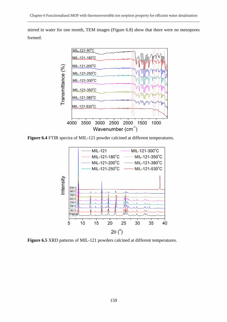
Chapter 6 Functionalized MOF with thermoreversible ion sorption property for efficient water desalination
159
stirred in water for one month, TEM images (Figure 6.8) show that there were no mesopores
formed.
Figure 6.4 FTIR spectra of MIL-121 powder calcined at different temperatures.
Figure 6.5 XRD patterns of MIL-121 powders calcined at different temperatures.

Chapter 6 Functionalized MOF with thermoreversible ion sorption property for efficient water desalination
160
Figure 6.6 The adsorption capacity (1000 ppm NaCl solution) of PDMVBA-p-MIL-121
prepared with MIL-121 powders calcined at different temperatures, and 3 days of impregnation
time before polymerization.
Figure 6.7 The adsorption capacity (1000 ppm NaCl solution) of PDMVBA-p-MIL-121
prepared with different impregnation time before polymerization and MIL-121-300°C.
Figure 6.8 TEM images of (a) as-prepared MIL-121-300 °C and (b) after kept in water udner
stirring for one month.

Chapter 6 Functionalized MOF with thermoreversible ion sorption property for efficient water desalination
161
6.3.2 Morphology salt adsorption of MOFs
As shown in Figure 6.9, MIL-121 crystals demonstrate a smooth surface and clear, distinct
edges. However, after the polymerization of DMVBA inside and on the crystals, MIL-121 is
covered by the polymer, and the crystal edge becomes smooth and blurred. PDMVBA-p-MIL-
121 was also studied for adsorbing ions from 1000 ppm NaCl and MgCl2 solutions in
comparison with pure PDMVBA, MIL-121-300°C, and the result is shown in Figure 6.9c and
Figure 6.10. After overnight adsorption, the adsorption capacities of PDMVBA-p-MIL-121
were 0.39 and 0.07 meq/g for NaCl and MgCl2, respectively. By contrast, those of pure
PDMVBA and MIL-121-300°C powders did not adsorb monovalent and divalent ions at all.
Figure 6.9 Characterization of MIL-121 and PDMVBA-p-MIL-121. SEM images of (a) MIL-
121-300 °C and (b) PDMVBA-p-MIL-121. (c) NaCl adsorption capacity of PDMVBA, MIL-
121-300°C and PDMVBA-p-MIL-121. (d) XRD patterns of as-prepared MIL-121, MIL-121-
300 °C, and PDMVBA-p-MIL-121 before and after NaCl adsorption. The red arrows on the
peaks show the peak shift of pattern MIL-121-300 °C compared with the XRD pattern of MIL-
121. (e) FTIR spectra of MIL-121-300 °C, and PDMVBA-p-MIL-121 before and after NaCl
adsorption.
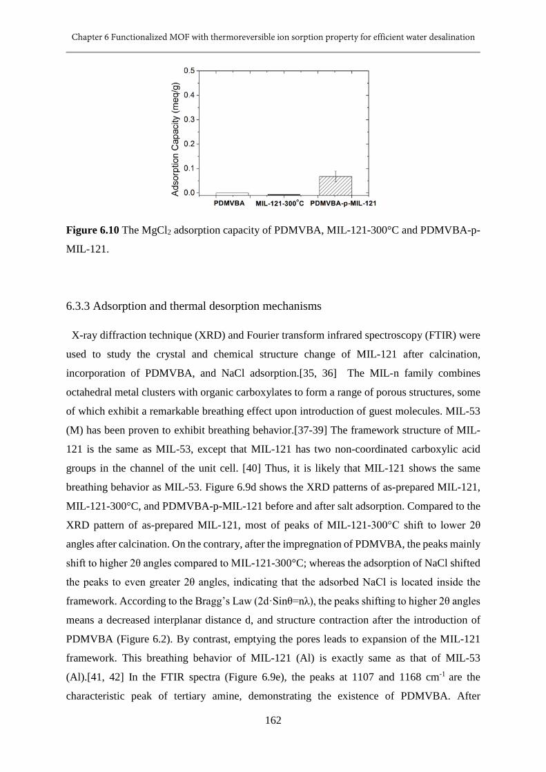
Chapter 6 Functionalized MOF with thermoreversible ion sorption property for efficient water desalination
162
Figure 6.10 The MgCl2 adsorption capacity of PDMVBA, MIL-121-300°C and PDMVBA-p-
MIL-121.
6.3.3 Adsorption and thermal desorption mechanisms
X-ray diffraction technique (XRD) and Fourier transform infrared spectroscopy (FTIR) were
used to study the crystal and chemical structure change of MIL-121 after calcination,
incorporation of PDMVBA, and NaCl adsorption.[35, 36] The MIL-n family combines
octahedral metal clusters with organic carboxylates to form a range of porous structures, some
of which exhibit a remarkable breathing effect upon introduction of guest molecules. MIL-53
(M) has been proven to exhibit breathing behavior.[37-39] The framework structure of MIL-
121 is the same as MIL-53, except that MIL-121 has two non-coordinated carboxylic acid
groups in the channel of the unit cell. [40] Thus, it is likely that MIL-121 shows the same
breathing behavior as MIL-53. Figure 6.9d shows the XRD patterns of as-prepared MIL-121,
MIL-121-300°C, and PDMVBA-p-MIL-121 before and after salt adsorption. Compared to the
XRD pattern of as-prepared MIL-121, most of peaks of MIL-121-300°C shift to lower 2θ
angles after calcination. On the contrary, after the impregnation of PDMVBA, the peaks mainly
shift to higher 2θ angles compared to MIL-121-300°C; whereas the adsorption of NaCl shifted
the peaks to even greater 2θ angles, indicating that the adsorbed NaCl is located inside the
framework. According to the Bragg’s Law (2d·Sinθ=nλ), the peaks shifting to higher 2θ angles
means a decreased interplanar distance d, and structure contraction after the introduction of
PDMVBA (Figure 6.2). By contrast, emptying the pores leads to expansion of the MIL-121
framework. This breathing behavior of MIL-121 (Al) is exactly same as that of MIL-53
(Al).[41, 42] In the FTIR spectra (Figure 6.9e), the peaks at 1107 and 1168 cm-1 are the
characteristic peak of tertiary amine, demonstrating the existence of PDMVBA. After
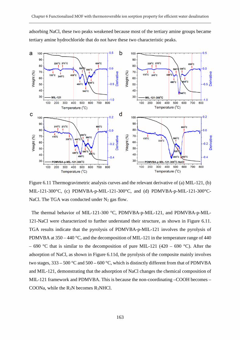
Chapter 6 Functionalized MOF with thermoreversible ion sorption property for efficient water desalination
163
adsorbing NaCl, these two peaks weakened because most of the tertiary amine groups became
tertiary amine hydrochloride that do not have these two characteristic peaks.
Figure 6.11 Thermogravimetric analysis curves and the relevant derivative of (a) MIL-121, (b)
MIL-121-300°C, (c) PDMVBA-p-MIL-121-300°C, and (d) PDMVBA-p-MIL-121-300°C-
NaCl. The TGA was conducted under N2 gas flow.
The thermal behavior of MIL-121-300 °C, PDMVBA-p-MIL-121, and PDMVBA-p-MIL-
121-NaCl were characterized to further understand their structure, as shown in Figure 6.11.
TGA results indicate that the pyrolysis of PDMVBA-p-MIL-121 involves the pyrolysis of
PDMVBA at 350 – 440 °C, and the decomposition of MIL-121 in the temperature range of 440
– 690 °C that is similar to the decomposition of pure MIL-121 (420 – 690 °C). After the
adsorption of NaCl, as shown in Figure 6.11d, the pyrolysis of the composite mainly involves
two stages, 333 – 500 °C and 500 – 600 °C, which is distinctly different from that of PDMVBA
and MIL-121, demonstrating that the adsorption of NaCl changes the chemical composition of
MIL-121 framework and PDMVBA. This is because the non-coordinating –COOH becomes –
COONa, while the R3N becomes R3NHCl.
Chapter 6 Functionalized MOF with thermoreversible ion sorption property for efficient water desalination
164
In the aqueous solution, the carboxylic acid and protonated tertiary amine exhibit the
following equilibrium: 3, 4
+− +↔ HRCOORCOOH ][
][][1 RCOOH
HRCOOKa+− ⋅
= (1)
++ +↔+ OHNROHNHR 3323 ][][
][][
23
332 OHNHR
OHNRKa⋅
⋅= +
+
(2)
At 30 °C or above, the pKa value of carboxylic acid increases with increasing temperature,[43,
44] while the pKa value of protonated tertiary amine decreases.[45, 46] At lower temperatures,
the dissociation of RCOOH and protonation of R3N facilitate mutually, which may strengthen
the acidity of carboxylic acid group and the basicity of tertiary amine group, giving rise to the
ability to adsorb monovalent ions; however, at elevated temperature, the protonation of RCOO-
and the deprotonation of R3NH+ promote mutually, resulting in the release of adsorbed salts,
as shown in Figure 6.2. As a result, the adsorption and thermal regeneration mechanism can be
described as follows:
NHClRRCOONaNaClNRRCOOH 33 +↔++ (3)
6.3.4 NaCl adsorption capacity of amphoteric MOFs
The amphoteric PDMVBA-p-MIL-121 exhibits high NaCl adsorption capacity. The loading
of PDMVBA in the PDMVBA-p-MIL-121 is determined to be 19.3 ± 2.3 wt. % based on the
change of sample weight, which is consistent with 17.9 wt. % obtained from the TG analysis.
The ratio of the polymer (PDMVBA) penetrated and coated on surface was calculated to be
79:21 on the basis of the thickness of polymer coating, confirming that the majority of the
polymer was incorporated into the porous channels of MIL-121. The theoretical maximum
adsorption capacity of PDMVBA-p-MIL-121 is calculated to be 1.20 meq/g on the basis of
19.3 wt. % of PDMVBA loading. The adsorption experiments show that the ion adsorption
capacity of PDMVBA-p-MIL-121 is dependent on the ion concentration. As shown in Figure
6.12, upon the increase of NaCl concentration, the adsorption capacity of PDMVBA-p-MIL-
121 increases and reaches equilibrium at 10000 ppm NaCl aqueous solution after overnight
adsorption. The equilibrium NaCl adsorption capacity is 0.92 meq/g, accounting for 77 % of
the theoretical maximum value; this indicates most of the ion adsorption sites accessible to
ions. When NaCl concentration decreases to 500 ppm, the adsorption capacity drops to 0.13
meq/g. Given < 600 ppm of total dissolved solids in good quality drinking water according to
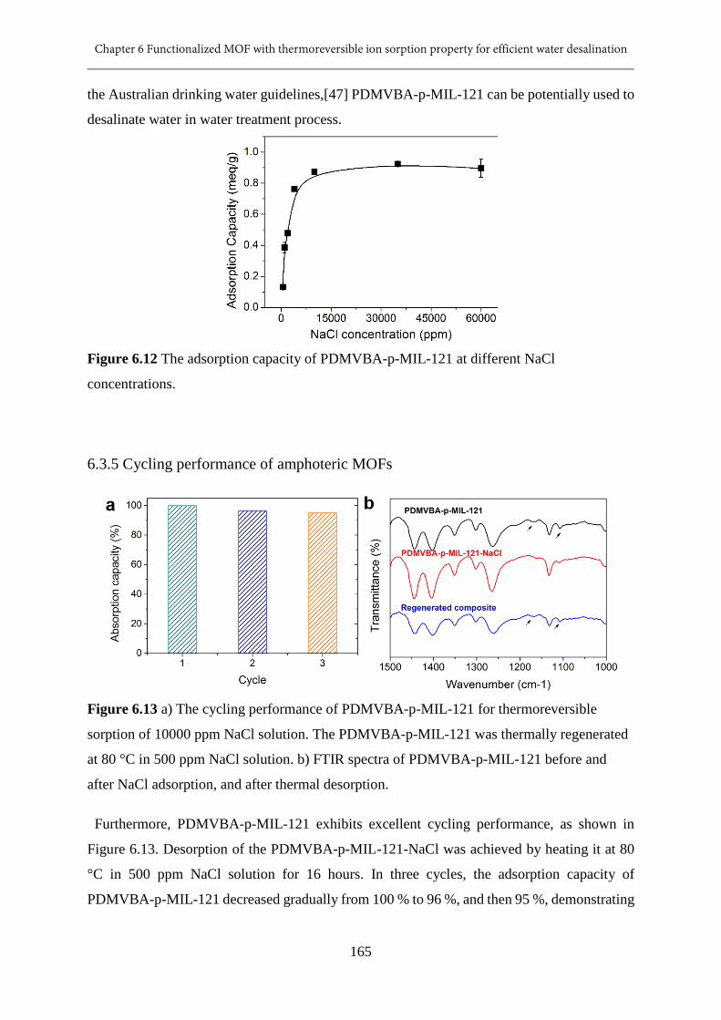
Chapter 6 Functionalized MOF with thermoreversible ion sorption property for efficient water desalination
165
the Australian drinking water guidelines,[47] PDMVBA-p-MIL-121 can be potentially used to
desalinate water in water treatment process.
Figure 6.12 The adsorption capacity of PDMVBA-p-MIL-121 at different NaCl
concentrations.
6.3.5 Cycling performance of amphoteric MOFs
Figure 6.13 a) The cycling performance of PDMVBA-p-MIL-121 for thermoreversible
sorption of 10000 ppm NaCl solution. The PDMVBA-p-MIL-121 was thermally regenerated
at 80 °C in 500 ppm NaCl solution. b) FTIR spectra of PDMVBA-p-MIL-121 before and
after NaCl adsorption, and after thermal desorption.
Furthermore, PDMVBA-p-MIL-121 exhibits excellent cycling performance, as shown in
Figure 6.13. Desorption of the PDMVBA-p-MIL-121-NaCl was achieved by heating it at 80
°C in 500 ppm NaCl solution for 16 hours. In three cycles, the adsorption capacity of
PDMVBA-p-MIL-121 decreased gradually from 100 % to 96 %, and then 95 %, demonstrating
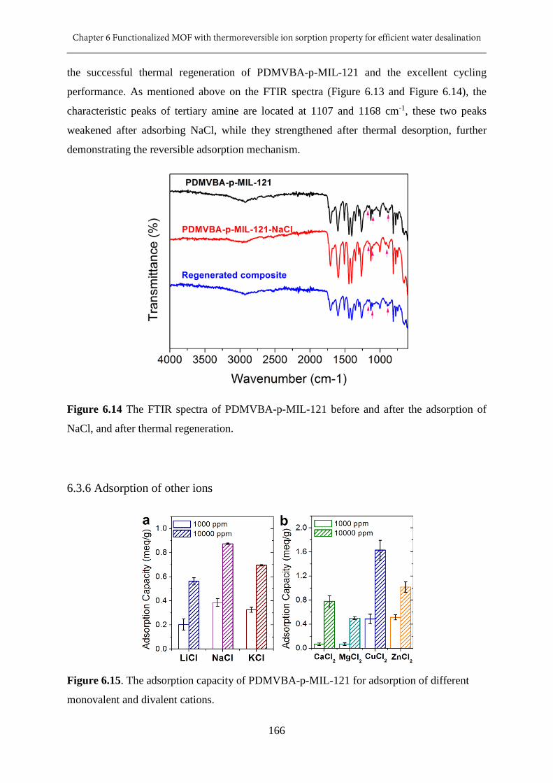
Chapter 6 Functionalized MOF with thermoreversible ion sorption property for efficient water desalination
166
the successful thermal regeneration of PDMVBA-p-MIL-121 and the excellent cycling
performance. As mentioned above on the FTIR spectra (Figure 6.13 and Figure 6.14), the
characteristic peaks of tertiary amine are located at 1107 and 1168 cm-1, these two peaks
weakened after adsorbing NaCl, while they strengthened after thermal desorption, further
demonstrating the reversible adsorption mechanism.
Figure 6.14 The FTIR spectra of PDMVBA-p-MIL-121 before and after the adsorption of
NaCl, and after thermal regeneration.
6.3.6 Adsorption of other ions
Figure 6.15. The adsorption capacity of PDMVBA-p-MIL-121 for adsorption of different
monovalent and divalent cations.
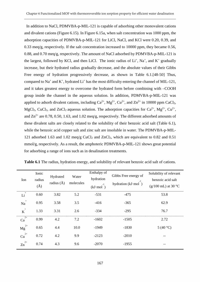
Chapter 6 Functionalized MOF with thermoreversible ion sorption property for efficient water desalination
167
In addition to NaCl, PDMVBA-p-MIL-121 is capable of adsorbing other monovalent cations
and divalent cations (Figure 6.15). In Figure 6.15a, when salt concentration was 1000 ppm, the
adsorption capacities of PDMVBA-p-MIL-121 for LiCl, NaCl, and KCl were 0.20, 0.39, and
0.33 meq/g, respectively. If the salt concentration increased to 10000 ppm, they became 0.56,
0.88, and 0.70 meq/g, respectively. The amount of NaCl adsorbed by PDMVBA-p-MIL-121 is
the largest, followed by KCl, and then LiCl. The ionic radius of Li+, Na+, and K+ gradually
increase, but their hydrated radius gradually decrease, and the absolute values of their Gibbs
Free energy of hydration progressively decrease, as shown in Table 6.1.[48-50] Thus,
compared to Na+ and K+, hydrated Li+ has the most difficulty entering the channel of MIL-121,
and it takes greatest energy to overcome the hydrated form before combining with –COOH
group inside the channel in the aqueous solution. In addition, PDMVBA-p-MIL-121 was
applied to adsorb divalent cations, including Ca2+, Mg2+, Cu2+, and Zn2+ in 10000 ppm CaCl2,
MgCl2, CuCl2, and ZnCl2 aqueous solution. The adsorption capacities for Ca2+, Mg2+, Cu2+,
and Zn2+ are 0.78, 0.50, 1.63, and 1.02 meq/g, respectively. The different adsorbed amounts of
these divalent salts are closely related to the solubility of their benzoic acid salt (Table 6.1),
while the benzoic acid copper salt and zinc salt are insoluble in water. The PDMVBA-p-MIL-
121 adsorbed 1.63 and 1.02 meq/g CuCl2 and ZnCl2, which are equivalent to 0.82 and 0.51
mmol/g, respectively. As a result, the amphoteric PDMVBA-p-MIL-121 shows great potential
for adsorbing a range of ions such as in desalination treatments.
Table 6.1 The radius, hydration energy, and solubility of relevant benzoic acid salt of cations.
Ion
Ionic
radius
(Å)
Hydrated
radius (Å)
Water
molecules
Enthalpy of
hydration
(kJ·mol-1
)
Gibbs Free energy of
hydration (kJ·mol-1
)
Solubility of relevant
benzoic acid salt
(g/100 mL) at 30 °C
Li+ 0.60 3.82 5.2 -531 -475 53.8
Na+ 0.95 3.58 3.5 -416 -365 62.9
K+ 1.33 3.31 2.6 -334 -295 76.7
Ca2+
0.99 4.2 7.2 -1602 -1505 2.72
Mg2+
0.65 4.4 10.0 -1949 -1830 5 (40 °C)
Cu2+
0.72 4.2 9.9 -2123 -2010 --
Zn2+
0.74 4.3 9.6 -2070 -1955 --
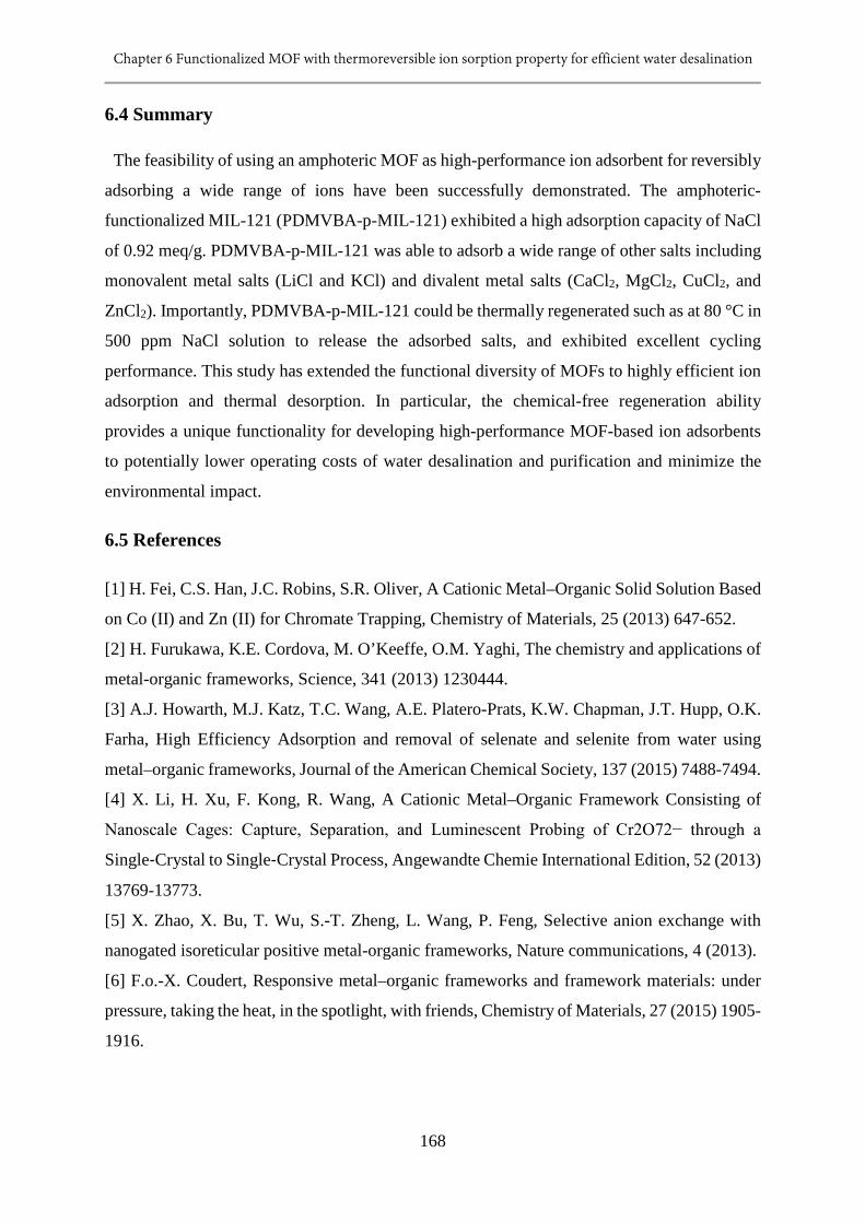
Chapter 6 Functionalized MOF with thermoreversible ion sorption property for efficient water desalination
168
6.4 Summary
The feasibility of using an amphoteric MOF as high-performance ion adsorbent for reversibly
adsorbing a wide range of ions have been successfully demonstrated. The amphoteric-
functionalized MIL-121 (PDMVBA-p-MIL-121) exhibited a high adsorption capacity of NaCl
of 0.92 meq/g. PDMVBA-p-MIL-121 was able to adsorb a wide range of other salts including
monovalent metal salts (LiCl and KCl) and divalent metal salts (CaCl2, MgCl2, CuCl2, and
ZnCl2). Importantly, PDMVBA-p-MIL-121 could be thermally regenerated such as at 80 °C in
500 ppm NaCl solution to release the adsorbed salts, and exhibited excellent cycling
performance. This study has extended the functional diversity of MOFs to highly efficient ion
adsorption and thermal desorption. In particular, the chemical-free regeneration ability
provides a unique functionality for developing high-performance MOF-based ion adsorbents
to potentially lower operating costs of water desalination and purification and minimize the
environmental impact.
6.5 References
[1] H. Fei, C.S. Han, J.C. Robins, S.R. Oliver, A Cationic Metal–Organic Solid Solution Based
on Co (II) and Zn (II) for Chromate Trapping, Chemistry of Materials, 25 (2013) 647-652.
[2] H. Furukawa, K.E. Cordova, M. O’Keeffe, O.M. Yaghi, The chemistry and applications of
metal-organic frameworks, Science, 341 (2013) 1230444.
[3] A.J. Howarth, M.J. Katz, T.C. Wang, A.E. Platero-Prats, K.W. Chapman, J.T. Hupp, O.K.
Farha, High Efficiency Adsorption and removal of selenate and selenite from water using
metal–organic frameworks, Journal of the American Chemical Society, 137 (2015) 7488-7494.
[4] X. Li, H. Xu, F. Kong, R. Wang, A Cationic Metal–Organic Framework Consisting of
Nanoscale Cages: Capture, Separation, and Luminescent Probing of Cr2O72− through a
Single‐Crystal to Single‐Crystal Process, Angewandte Chemie International Edition, 52 (2013)
13769-13773.
[5] X. Zhao, X. Bu, T. Wu, S.-T. Zheng, L. Wang, P. Feng, Selective anion exchange with
nanogated isoreticular positive metal-organic frameworks, Nature communications, 4 (2013).
[6] F.o.-X. Coudert, Responsive metal–organic frameworks and framework materials: under
pressure, taking the heat, in the spotlight, with friends, Chemistry of Materials, 27 (2015) 1905-
1916.
Chapter 6 Functionalized MOF with thermoreversible ion sorption property for efficient water desalination
169
[7] J. Park, D. Yuan, K.T. Pham, J.-R. Li, A. Yakovenko, H.-C. Zhou, Reversible alteration of
CO2 adsorption upon photochemical or thermal treatment in a metal–organic framework,
Journal of the American Chemical Society, 134 (2011) 99-102.
[8] M.A.C. Stuart, W.T. Huck, J. Genzer, M. Müller, C. Ober, M. Stamm, G.B. Sukhorukov,
I. Szleifer, V.V. Tsukruk, M. Urban, Emerging applications of stimuli-responsive polymer
materials, Nature materials, 9 (2010) 101-113.
[9] X. Meng, B. Gui, D. Yuan, M. Zeller, C. Wang, Mechanized azobenzene-functionalized
zirconium metal-organic framework for on-command cargo release, Science Advances, 2
(2016) e1600480.
[10] D. Chen, D. Yang, C. Dougherty, W. Lu, H. Wu, X. He, T. Cai, M.E. Van Dort, B.D.
Ross, H. Hong, In Vivo Targeting and Positron Emission Tomography Imaging of Tumor with
Intrinsically Radioactive Metal-Organic Frameworks Nanomaterials, ACS nano, (2017).
[11] K. Mandel, T. Granath, T. Wehner, M. Rey, W. Stracke, N. Vogel, G. Sextl, K. Mueller-
Buschbaum, Smart Optical Composite Materials: Dispersions of Metal-Organic Framework@
Superparamagnetic Microrods for Switchable Isotropic-Anisotropic Optical Properties, ACS
nano, (2016).
[12] S.S. Nagarkar, A.V. Desai, S.K. Ghosh, Stimulus‐Responsive Metal–Organic
Frameworks, Chemistry–An Asian Journal, 9 (2014) 2358-2376.
[13] S.-L. Li, Q. Xu, Metal–organic frameworks as platforms for clean energy, Energy &
Environmental Science, 6 (2013) 1656-1683.
[14] A. Dąbrowski, Adsorption—from theory to practice, Advances in colloid and interface
science, 93 (2001) 135-224.
[15] S.D. Alexandratos, Ion-exchange resins: a retrospective from industrial and engineering
chemistry research, Industrial & Engineering Chemistry Research, 48 (2008) 388-398.
[16] M.E. Davis, Ordered porous materials for emerging applications, Nature, 417 (2002) 813-
821.
[17] J. Rouquerol, F. Rouquerol, P. Llewellyn, G. Maurin, K.S. Sing, Adsorption by powders
and porous solids: principles, methodology and applications, Academic press, 2013.
[18] P. Li, S.-Y. Moon, M.A. Guelta, L. Lin, D.A. Gómez-Gualdrón, R.Q. Snurr, S.P. Harvey,
J.T. Hupp, O.K. Farha, Nanosizing a Metal–Organic Framework Enzyme Carrier for
Accelerating Nerve Agent Hydrolysis, ACS nano, 10 (2016) 9174-9182.
[19] V. Stavila, R.K. Bhakta, T.M. Alam, E.H. Majzoub, M.D. Allendorf, Reversible hydrogen
storage by NaAlH4 confined within a titanium-functionalized MOF-74 (Mg) nanoreactor, ACS
nano, 6 (2012) 9807-9817.
Chapter 6 Functionalized MOF with thermoreversible ion sorption property for efficient water desalination
170
[20] M. Carboni, C.W. Abney, S. Liu, W. Lin, Highly porous and stable metal–organic
frameworks for uranium extraction, Chemical Science, 4 (2013) 2396-2402.
[21] A.J. Howarth, T.C. Wang, S.S. Al-Juaid, S.G. Aziz, J.T. Hupp, O.K. Farha, Efficient
extraction of sulfate from water using a Zr-metal–organic framework, Dalton Transactions, 45
(2016) 93-97.
[22] C. Wang, X. Liu, J.P. Chen, K. Li, Superior removal of arsenic from water with zirconium
metal-organic framework UiO-66, Scientific reports, 5 (2015).
[23] H. Fei, D.L. Rogow, S.R. Oliver, Reversible anion exchange and catalytic properties of
two cationic metal− organic frameworks based on Cu (I) and Ag (I), Journal of the American
Chemical Society, 132 (2010) 7202-7209.
[24] H.-R. Fu, Z.-X. Xu, J. Zhang, Water-stable metal–organic frameworks for fast and high
dichromate trapping via single-crystal-to-single-crystal ion exchange, Chemistry of Materials,
27 (2014) 205-210.
[25] P.-F. Shi, B. Zhao, G. Xiong, Y.-L. Hou, P. Cheng, Fast capture and separation of, and
luminescent probe for, pollutant chromate using a multi-functional cationic heterometal-
organic framework, Chemical Communications, 48 (2012) 8231-8233.
[26] H. Fei, M.R. Bresler, S.R. Oliver, A new paradigm for anion trapping in high capacity and
selectivity: Crystal-to-crystal transformation of cationic materials, Journal of the American
Chemical Society, 133 (2011) 11110-11113.
[27] N. Zhang, X. Yang, X. Yu, Y. Jia, J. Wang, L. Kong, Z. Jin, B. Sun, T. Luo, J. Liu, Al-1,
3, 5-benzenetricarboxylic metal–organic frameworks: A promising adsorbent for
defluoridation of water with pH insensitivity and low aluminum residual, Chemical
Engineering Journal, 252 (2014) 220-229.
[28] X.-P. Zhou, Z. Xu, M. Zeller, A.D. Hunter, Reversible uptake of HgCl 2 in a porous
coordination polymer based on the dual functions of carboxylate and thioether, Chemical
Communications, (2009) 5439-5441.
[29] D. Li, Y.S. Yan, H.T. Wang, Recent advances in polymer and polymer composite
membranes for reverse and forward osmosis processes, Prog. Polym. Sci., 61 (2016) 104-155.
[30] D. Li, H.T. Wang, Recent developments in reverse osmosis desalination membranes, J.
Mater. Chem., 20 (2010) 4551-4566.
[31] C. Volkringer, T. Loiseau, N. Guillou, G.r. Férey, M. Haouas, F. Taulelle, E. Elkaim, N.
Stock, High-Throughput Aided Synthesis of the Porous Metal− Organic Framework-Type
Aluminum Pyromellitate, MIL-121, with Extra Carboxylic Acid Functionalization, Inorganic
chemistry, 49 (2010) 9852-9862.
Chapter 6 Functionalized MOF with thermoreversible ion sorption property for efficient water desalination
171
[32] J.J. Christensen, R.M. Izatt, D.P. Wrathall, L.D. Hansen, Thermodynamics of proton
ionization in dilute aqueous solution. Part XI. pK, Δ H°, and Δ S° values for proton ionization
from protonated amines at 25°, Journal of the Chemical Society A: Inorganic, Physical,
Theoretical, (1969) 1212-1223.
[33] J.-N. Hao, B. Yan, Ag+-sensitized lanthanide luminescence in Ln 3+ post-functionalized
metal–organic frameworks and Ag+ sensing, Journal of Materials Chemistry A, 3 (2015) 4788-
4792.
[34] J.-N. Hao, B. Yan, Highly sensitive and selective fluorescent probe for Ag+ based on a Eu
3+ post-functionalized metal–organic framework in aqueous media, Journal of Materials
Chemistry A, 2 (2014) 18018-18025.
[35] C. Volkringer, T. Loiseau, N. Guillou, G. Férey, E. Elkaïm, A. Vimont, XRD and IR
structural investigations of a particular breathing effect in the MOF-type gallium terephthalate
MIL-53 (Ga), Dalton Transactions, (2009) 2241-2249.
[36] C. Serre, F. Millange, C. Thouvenot, M. Noguès, G. Marsolier, D. Louër, G. Férey, Very
Large Breathing Effect in the First Nanoporous Chromium (III)-Based Solids: MIL-53 or CrIII
(OH)⊙{O2C− C6H4− CO2}⊙{HO2C− C6H4− CO2H} x⊙ H2O y, Journal of the American
Chemical Society, 124 (2002) 13519-13526.
[37] G. Férey, C. Serre, Large breathing effects in three-dimensional porous hybrid matter:
facts, analyses, rules and consequences, Chemical Society Reviews, 38 (2009) 1380-1399.
[38] F. Millange, C. Serre, N. Guillou, G. Ferey, R.I. Walton, Structural effects of solvents on
the breathing of metal–organic frameworks: an in situ diffraction study, Angewandte Chemie,
120 (2008) 4168-4173.
[39] C. Serre, C. Mellot-Draznieks, S. Surblé, N. Audebrand, Y. Filinchuk, G. Férey, Role of
solvent-host interactions that lead to very large swelling of hybrid frameworks, Science, 315
(2007) 1828-1831.
[40] T. Loiseau, C. Serre, C. Huguenard, G. Fink, F. Taulelle, M. Henry, T. Bataille, G. Férey,
A Rationale for the Large Breathing of the Porous Aluminum Terephthalate (MIL‐53) Upon
Hydration, Chemistry–A European Journal, 10 (2004) 1373-1382.
[41] F. Millange, N. Guillou, R.I. Walton, J.-M. Grenèche, I. Margiolaki, G. Férey, Effect of
the nature of the metal on the breathing steps in MOFs with dynamic frameworks, Chemical
Communications, (2008) 4732-4734.
[42] T.K. Trung, P. Trens, N. Tanchoux, S. Bourrelly, P.L. Llewellyn, S. Loera-Serna, C. Serre,
T. Loiseau, F. Fajula, G. Férey, Hydrocarbon adsorption in the flexible metal organic
Chapter 6 Functionalized MOF with thermoreversible ion sorption property for efficient water desalination
172
frameworks MIL-53 (Al, Cr), Journal of the American Chemical Society, 130 (2008) 16926-
16932.
[43] T. Matsui, H.C. Ko, L.G. Hepler, Calorimetric Heats of Ionization of Aqueous Benzoic
Acid from 5-100° C and Derived Thermodynamic Quantities, Canadian Journal of Chemistry,
52 (1974) 2912-2918.
[44] J.K. Sa‘ib, Titrimetric Study of the Solubility and Dissociation of Benzoic Acid in Water:
Effect of Ionic Strength and Temperature, American Journal of Analytical Chemistry, 6 (2015)
429.
[45] E.S. Hamborg, G.F. Versteeg, Dissociation constants and thermodynamic properties of
amines and alkanolamines from (293 to 353) K, Journal of Chemical & Engineering Data, 54
(2009) 1318-1328.
[46] M. Gupta, E.F. da Silva, H.F. Svendsen, Modeling temperature dependency of amine
basicity using PCM and SM8T implicit solvation models, The Journal of Physical Chemistry
B, 116 (2012) 1865-1875.
[47] Australian Drinking Water Guidelines 6, Australian Government: National Health and
Medical Research Council, National Resource Management Ministerial Council, (2004).
[48] M.H. Abraham, Y. Marcus, The thermodynamics of solvation of ions. Part 1.—The heat
capacity of hydration at 298.15 K, Journal of the Chemical Society, Faraday Transactions 1:
Physical Chemistry in Condensed Phases, 82 (1986) 3255-3274.
[49] Y. Marcus, The thermodynamics of solvation of ions. Part 2.—The enthalpy of hydration
at 298.15 K, Journal of the Chemical Society, Faraday Transactions 1: Physical Chemistry in
Condensed Phases, 83 (1987) 339-349.
[50] Y. Marcus, Thermodynamics of solvation of ions. Part 5.—Gibbs free energy of hydration
at 298.15 K, Journal of the Chemical Society, Faraday Transactions, 87 (1991) 2995-2999.
Chapter 7 Conclusion and Future Work
173
Chapter 7 Conclusion and Future Work
7.1 Conclusion
In this thesis, thermo-responsive ability is successfully introduced to the materials for water
treatment, including responsive membrane, responsive draw agent, and responsive ion
adsorbent. Through the exploration in this thesis, it can be concluded that: 1) introduction of
thermally responsive polymer endows the responsive membrane with controllable separation
ability and high separation efficiency due to the switchable wettability and the hierarchical
structure that enlarged them to superhydrophilicity and superhydrophobicity for improved
treatment performance. 2) The swelling behavior / kinetic study efficiently reveals the swelling
pressure and FO performance of thermally responsive hydrogel draw agent, advancing the
development of desired draw agent. 3) Thermally reversible ion sorption is achieved inside the
metal organic framework by amphoteric functionalization, showing high adsorption capacity,
accessibility of ion adsorption sites, and excellent cycling performance.
In chapter 3, a robust thermo-responsive polymer membrane with switchable superhy-
drophilicity and superhydrophobicity was successfully fabricated by evenly coating poly (N-
isopropylacrylamide) (PNIPAM) on a thermoplastic polyurethane (TPU) microfibres mat. In
addition, other polymeric micro- or nanofibres membranes could be used as the substrates for
fabricating superwetting materials, which broadens the methods of preparation of such
materials. Among the polymer composite membranes prepared in this study, the TPU-
PNIPAM-3.6 material performed best, exhibiting excellent mechanical properties, switchable
superwettability, fast swelling – deswelling behaviour, and best oil water emulsion separation
capacity. Driven by gravity only, the TPU-PNIPAM-3.6 membrane could separate 1 wt. %
silicone oil-water emulsion at room temperature with a separation efficiency of ≥ 99.26 %, and
separate 99 wt. % silicone oil-water emulsions at 45 °C with a separation efficiency of ≥
99.85 %. This membrane is a good candidate for not only oil-water emulsion separation, but
also for fabricating smart materials for rapidly responsive drug delivery systems and sensors.
In chapter 4, the swelling pressure of polymer hydrogels was enhanced by incorporating TPU
microfibres, and thus improving the forward osmosis performance of hydrogel composites.
This study is based on our group’s previous study, by modifying the pure responsive hydrogel,
and applied in the process as a monolith. TPU-hydrogel composite monolith generated a water
flux that are about twice of those of pure hydrogel particle. In terms of the dewatering

Chapter 7 Conclusion and Future Work
174
performance, the dewatering flux of TPU-hydrogel composite almost two times of that of pure
hydrogel particles as well. Further study indicated that the hydrophilicity of wet TPU
microfibres and the capillary effect generated by microchannels around them resulted in greatly
enhanced water absorption ability and water diffusion rate, and sustained swelling pressure of
the polymer hydrogels. The composite hydrogel therefore induced significantly higher forward
osmosis water flux and dewatering flux compared to pure hydrogel particles. This study
provides a simple and effective strategy for improving water transport through hydrogel
structure and sustaining swelling pressure of stimuli-responsive polymer hydrogel, which is
very promising for designing high-performance draw agent for forward osmosis application.
In chapter 5, a hydrogel-PET microfibre composite is prepared by compressing the PET
microfibres added during polymerization of hydrogel, and studied as a forward osmosis draw
agent. The combination of a hydrophilic ionic hydrogel and a hydrophobic PET microfibre
imparted to the composite hydrogel porosity, due to different wettabilities, whilst at the same
time providing an additional relaxation force during swelling because of the compression
pressure applied during the preparation. As observed in the experiment, the porous structure
and the PET microfibre decreased the sizes of hydrogel domains, increasing solvent diffusion.
On the other hand, the characteristic exponent n of the composites decreased with increasing
PET microfibre loading and increasing amount of compression. The hydrogel-PET composites
exhibited Less Fickian diffusion, indicating that the polymer chain relaxation rate is much
faster than the solvent diffusion rate. With regards the forward osmosis application, the water
flux of hydrogels is consistent with the swelling kinetics result, i.e., it increased with increasing
PET microfibre loading and increasing compression pressure.
In order to study the effect of hydrophilic or hydrophobic microfibres on the composite draw
agent, a relatively hydrophilic polydopamine-modified microfibre (hydrogel-D-PET) was
prepared and fabricated with hydrogel to obtain a composite. The composite with hydrophobic
microfibre was better at maintaining higher water flux in a long period test, but the dewatering
performance reduced. While the addition of hydrophilic microfibre improved both FO water
flux and dewatering flux.
This work demonstrates that the performance of forward osmosis hydrogel draw agent is
closely related to the swelling properties of hydrogel, and the draw agent performance can be
effectively improved by tailoring its swelling properties.
Chapter 7 Conclusion and Future Work
175
In chapter 6, an amphoteric MOF is fabricated by integrating weak acid groups with weak
base groups together in a porous metal organic framework (MOF) to achieve thermally
reversible ion sorption property. The feasibility for reversibly adsorbing a wide range of ions
has been successfully demonstrated. PDMVBA-p-MIL-121 could adsorb a wide range of other
salts including monovalent metal salts (LiCl and KCl) and divalent metal salts (CaCl2, MgCl2,
CuCl2, and ZnCl2). The amphoteric-functionalized MIL-121 (PDMVBA-p-MIL-121)
exhibited a high NaCl adsorption capacity of 0.92 meq/g. Importantly, PDMVBA-p-MIL-121
could be thermally regenerated such as at 80 °C in 500 ppm NaCl solution to release the
adsorbed salts, and exhibited excellent cycling performance. This study has extended the
functional diversity of MOFs to highly efficient ion adsorption and thermal desorption. In
particular, the chemical-free regeneration ability provides a unique functionality for developing
high-performance MOF-based ion adsorbents to potentially lower operating costs of water
desalination and purification and minimize the environmental impact.
7.2 Further Directions
The introduction of responsive ability endows the raw materials with new functionalities,
broadens their application, and enhances the relevant water treatment performance, as
illustrated in this study. However, the development of stimuli responsive water treatment
system with self-cleaning, self-refreshing, energy-saving, or controllable separation abilities is
still in an early stage, further development is challenge but highly desired.
Smart membrane. 1) The controllable separation process responds rapidly for selective
separation, tunable permeation and / or on-off state management, to achieve biomimetic
membrane ultimately. 2) Membrane fouling problems can be relieved by improving wettability
and the oscillation of responsive component to release attachments. The final objective is self-
cleaning membrane and anti-fouling membrane.
Smart forward osmosis draw agent. Ideal performance includes: 1) high osmotic pressure for
high water flux, 2) low back diffusion, 3) minimal toxicity and low cost, 4) easy and energy-
efficient regeneration, 5) good reusability. Importantly, the development of relevant theory or
mechanism, and a proper FO unit for continuous water production are particularly crucial.
Smart adsorbent. Rapid adsorption, high adsorption capacity, rapid regeneration, easy
collection, and good reusability constitute a desired adsorbent.