san francisco unified school district 2006 proposition … · san francisco unified school district...
TRANSCRIPT
Page 1 of 6
SAN FRANCISCO UNIFIED SCHOOL DISTRICT
2006 PROPOSITION A BOND PROGRAM 300 SENECA
NEW ACADEMIC CAMPUS
ADDENDUM NO. 1 PROJECT: 300 Seneca New Academic Campus DATE: May 19, 2014 New Classroom Addition 300 Seneca Ave., S.F., CA 94112 OWNER: San Francisco Unified School District 135 Van Ness Avenue San Francisco, CA 94103
Notice is hereby given to all prospective bidders that plans and specifications on the subject project are modified as hereinafter set forth. This Addendum shall be attached to and form a part of the plans and specifications. All bidders must acknowledge receipt of this addendum on the Bid Form. In case of difference with previous addenda or communications, this addendum takes precedence.
It is the responsibility of all bidders to notify all subcontractors from whom they request bids and from whom they accept bids of all changes contained in this addendum.
PROJECT MANUAL
1. Item No. AD1-PM1 Attachment: Narrative only – no sketch issued
Reference: SECTION 05500 METAL FABRICATIONS Description: Revise specification section 05500 Metal Fabrications to include the
following. 1.1.B.4. Division 07 flashing and sheet metalwork for transition from
gutters to downspouts. 2.2.N. Downspouts: Provide G-90 galvanized schedule 40 pipe with
1/4 inch hot-dip galvanized steel plate supports welded to pipe and secured to building.
2.9.B. Shop prime all other metal assemblies that are not galvanized as follows:
2.9.C. Galvanized assemblies shall be field primed.
Page 2 of 6
2. Item No. AD1-PM2 Attachment: Narrative only – no sketch issued
Reference: SECTION 07620 FLASHINGS AND SHEET METALWORK Description: Revise specification section 07620 Flashings and Sheet Metalwork to
include the following.
1.1.B.1. Division 05 Metal Fabrications for downspouts. 2.1.B.3. Gutters 22 ga. 2.1.B.5. Downspouts See Section 05500 2.3.C.1.e. To be removed 2.3.C.1.f. To be removed.
3. Item No. AD1-PM3
Attachment: Narrative only – no sketch issued Reference: SECTION 09900 METAL PAINT Description: Revise specification section 09900 Paint to include the following. 1.1.A.2.a. Field prime galvanized metal assemblies.
4. Item No. AD1-PM4 Attachment: Narrative only – no sketch issued
Reference: SECTION 02300 EARTHWORK Description: Revise specification section 02300 Earthwork to include the following.
3.14.A. A soil sampling report has been prepared and is available upon request.
3.14.B. For bidding purposes, the contractor shall assume that any soil
removed from the site will need to be disposed of at a permitted Class III Waste Management Unit. The District’s Consultant will collect the necessary stockpile soil samples utilizing the current acceptance criteria from Recology Class II Hay Road Landfill located in Vacaville, California, and the Waste Management Class II/III landfill in Altamont, California. The contractor shall allow a minimum of 14 calendar days for testing and analysis. The District does not clarify, or imply, that the removed soils will meet the DTSC classification for “Clean Soils” at Sensitive Sites. Any additional testing above the testing that is required for disposal at a permitted Class III Waste Management Unit will be at the contractor’s own risk and expense.
5. Item No. AD1-PM5
Attachment: Specification 32 90 00 Reference: SECTION 32 90 00 TREE PLANTING Description: Include attached specification section 32 90 00 Tree Planting.
6. Item No. AD1-PM6 Attachment: Specification 16860
Reference: SECTION 16860 EDUCATIONAL INTERCOMMUNICATIONS AND PROGRAM SYSTEMS
Description: Replace specification section 16860 Educational Intercommunications and Program Systems with attached.
Page 3 of 6
7. Item No. AD1-PM7 Attachment: Specification 16910
Reference: SECTION 16910 FIRE DETECTION AND ALARM Description: Replace specification section 16910 Fire Alarm System with attached.
8. Item No. AD1-PM8 Attachment: Specification 02820
Reference: SECTION 02820 CHAIN LINK FENCE Description: Include attached specification section 02820 Chain Link Fence.
9. Item No. AD1-PM9 Attachment: Specification 05810
Reference: SECTION 05810 EXPANSION JOINT COVERS Description: Include attached specification section 05810 Expansion Joints.
10. Item No. AD1-PM10 Attachment: Specification 07310
Reference: SECTION 07310 ASPHALT SHINGLES Description: Include attached specification section 07310 Asphalt Shingles.
Page 4 of 6
DRAWINGS: PACKAGE A
1. Item No. AD1-D1 Attachment: CSK-1 Reference: C3.1 Description: Revised limit of work per attached CSK-1.
2. Item No. AD1-D2
Attachment: CSK-2 Reference: C4.1 Description: Storm drain layout has been revised per attached CSK-2.
3. Item No. AD1-D3
Attachment: ASK-1 Reference: A1.01 Description: Remove and replace trees in-kind and size, per ASK-1. ASK-1
supersedes Key Note D6 on 3/A1.01.
4. Item No. AD1-D4 Attachment: ASK-2 Reference: A3.02 Description: Revise Building Section 8/A3.02 to have a vapor barrier below the slab on
grade.
5. Item No. AD1-D5 Attachment: ASK-3 Reference: A2.01 Description: Revise SECOND LEVEL FLOOR PLAN to include one evacuation chair
per stair. 6. Item No. AD1-D6
Attachment: ASK-4 Reference: A1.01 Description: Revise limit of work boundary line per attached ASK-4.
7. Item No. AD1-D7 Attachment: Narrative only – no sketch issued Reference: A2.01 Description: Revise Key Notes to include note N15 to read “PROVIDE GARAVENTA
EVACU-TRAC CD7 EVACUATION CHAIR”. 8. Item No. AD1-D8
Attachment: Narrative only – no sketch issued Reference: A1.01 Description: Revise Key Note N9 to read “(N) DRINKING FOUNTAIN, HAWS 3150
PEDESTAL FOUNTAIN WITH 5725 ENVIROGARD BUBBLER AND 6426 LEAD FILTER, WATER LINE TO BE CONNECTED FROM MAIN BUILDING”.
9. Item No. AD1-D9
Attachment: Narrative only – no sketch issued Reference: A1.01 Description: Revise Key Note N10 to read “RECYCLED PLASTIC BENCHES WITH
POWDER COATED STEEL FRAME AND LEGS. ACCEPTABLE MANUFACTURER IS PERMA-CAP BY HUSSEY SEATING COMPANY”.
Page 5 of 6
10. Item No. AD1-D10 Attachment: SKP-1 Reference: P2.01 Description: Revise Rain Water Leader connections east of grid line 4.C. Revise
Sewer Line connection to between grid lines 4.9 and 4.10. Revise Storm Drain Line connection to between grid lines 4.11 and 4.12.
11. Item No. AD1-D11 Attachment: E1.01 Reference: Y-E1.01 Description: Electrical site plan sheet E1.01 shall be added to the set “for reference
only”.
RFI RESPONSES
1. Question: Hazmat report and specification are missing.
Response: The only hazmat work for this project is the potential contaminated soil, refer to attached Soil Sampling and Analysis Report.
2. Question: Soils report doesn’t identify contamination, is it, confirmed?
Response: For complete soils report, refer to Addendum #1 attached Soil Sampling and
Analysis Report. 3. Question: There is no Specification for the Roof.
Response: See Addendum #1, attached Specification Section 07310 Asphalt Shingles.
4. Question: Drinking fountain Note N9 shown on Drawing A1.01 isn’t identified on plumbing
schedule and drawings, please identify water and sewer line connection for DF. Response: The waterline for the drinking fountain is to be connected from the Main Building.
5. Question: Per drawing A1.01 Note N2 provide specs for landscaping.
Response: See Addendum #1, attached specification section 32 09 00 Tree Planting.
6. Question: Per drawing A1.01 Note N4, N7, provide specs for chain link and elevation height.
Response: See Addendum #1, attached specification section 02820 Chain Link Fence. The elevation height for N4 chain link fence is at 4’-0” high, N7 chain link fence is at the height that will match what is adjacent.
7. Question: Per drawing A1.01 Note N10 provide specs and details for benches.
Response: See Addendum #1, Drawing Item No. AD1-D8. Note N10 is to read “RECYCLED PLASTIC BENCHES WITH POWDER COATED STEEL FRAME AND LEGS. ACCEPTABLE MANUFACTURER IS PERMA-CAP BY HUSSEY SEATING COMPANY”.
8. Question: All Key notes on Drawing C3.1 are not in the limit for this project. Are they shown for REFERENCE only?
Page 6 of 6
Response: The Key notes on Drawing C3.1 are part of a separate contract. On this sheet only, any key notes outside of the area of work are not applicable. Refer to Addendum #1, attached CSK-1.
9. Question: For the Proposed Asphalt Concrete Pavement shown on Horizontal Control Legend and Detail 2/Y-C4.1, impossible to identify the area of work, please clarify.
Response: See Addendum #1, attached CSK-2 for clarification.
10. Question: Please provide landscape scope of work.
Response: See Addendum #1: Drawing Item No. AD1-D3 and attached ASK-1.
11. Question: Please provide Specification for Expansion Joints as per Drawing A2.1 Key Note N10, N11
Response: See Addendum #1, attached specification section 05810 Expansion Joint Covers.
12. Question: Ref: Attached handrail spec vs sheet A8.05. Sheet A8.05 states the handrail and components are galvanized and specification note stainless steel, which is correct?
Response: The specification note is correct. Use Stainless Steel for all exterior handrails and railings.
END OF ADDENDUM
TECHNICAL SPECIFICATIONS TREE PLANTINGS 300 SENECA
Page 1 of 3
32 90 00 - 1
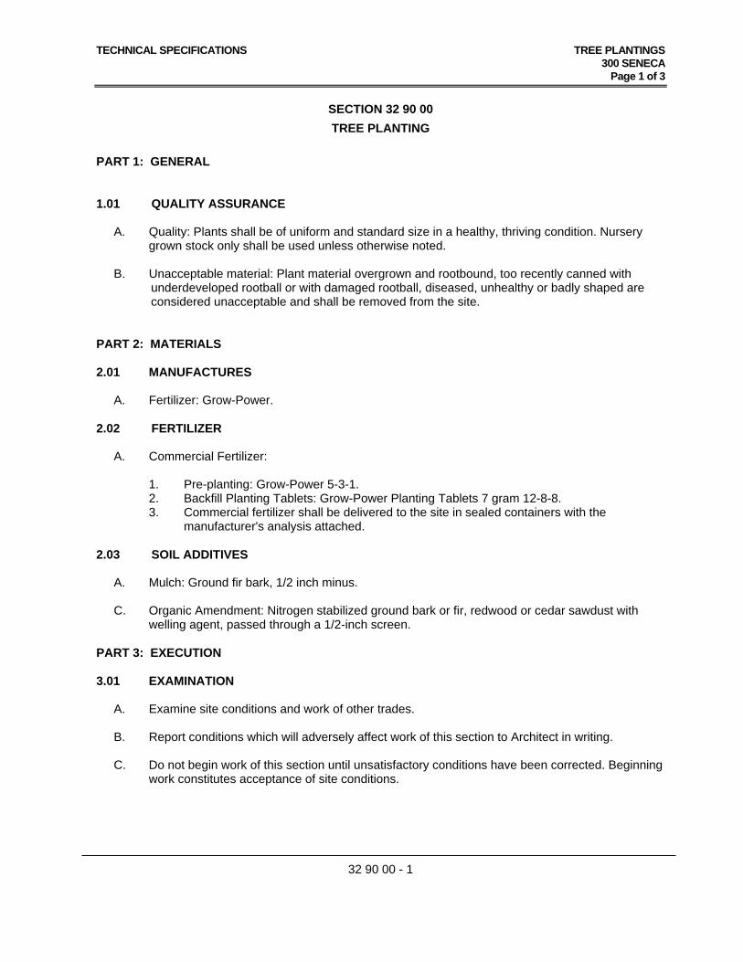
SECTION 32 90 00
TREE PLANTING
PART 1: GENERAL 1.01 QUALITY ASSURANCE
A. Quality: Plants shall be of uniform and standard size in a healthy, thriving condition. Nursery
grown stock only shall be used unless otherwise noted.
B. Unacceptable material: Plant material overgrown and rootbound, too recently canned with underdeveloped rootball or with damaged rootball, diseased, unhealthy or badly shaped are considered unacceptable and shall be removed from the site.
PART 2: MATERIALS 2.01 MANUFACTURES A. Fertilizer: Grow-Power. 2.02 FERTILIZER
A. Commercial Fertilizer:
1. Pre-planting: Grow-Power 5-3-1. 2. Backfill Planting Tablets: Grow-Power Planting Tablets 7 gram 12-8-8.
3. Commercial fertilizer shall be delivered to the site in sealed containers with the manufacturer's analysis attached.
2.03 SOIL ADDITIVES
A. Mulch: Ground fir bark, 1/2 inch minus.
C. Organic Amendment: Nitrogen stabilized ground bark or fir, redwood or cedar sawdust with welling agent, passed through a 1/2-inch screen.
PART 3: EXECUTION 3.01 EXAMINATION A. Examine site conditions and work of other trades.
B. Report conditions which will adversely affect work of this section to Architect in writing. C. Do not begin work of this section until unsatisfactory conditions have been corrected. Beginning
work constitutes acceptance of site conditions.
TECHNICAL SPECIFICATIONS TREE PLANTINGS 300 SENECA
Page 2 of 3
32 90 00 - 2
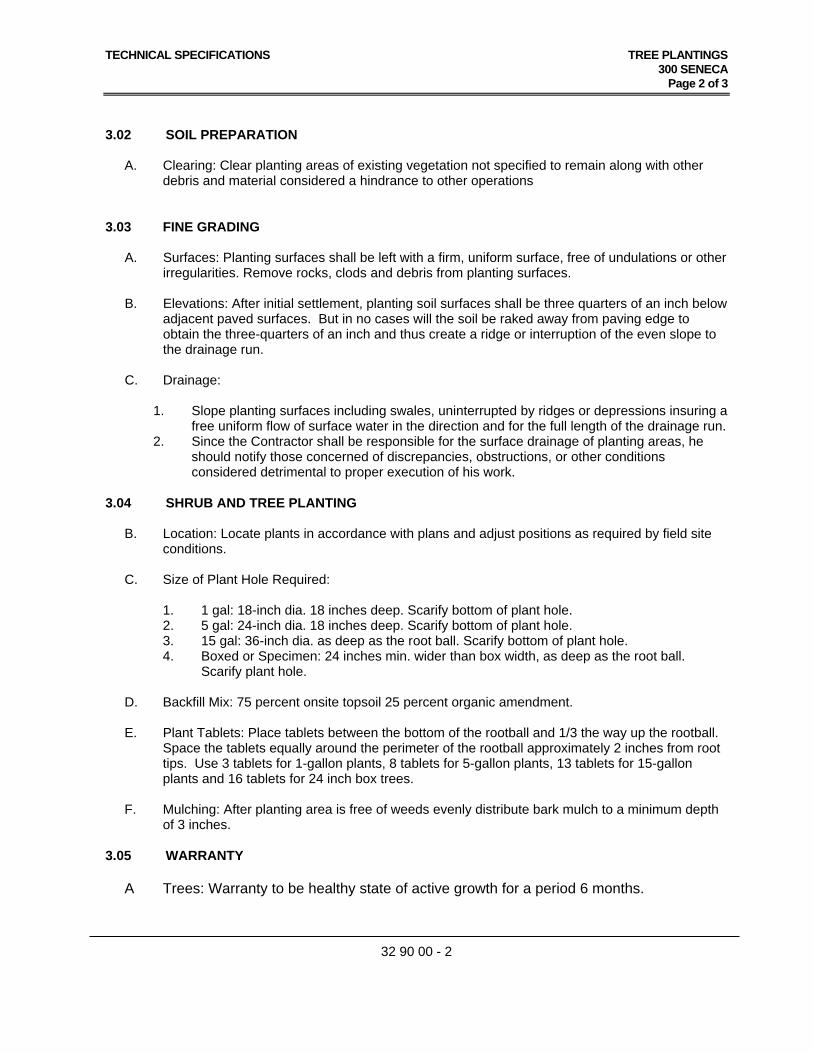
3.02 SOIL PREPARATION
A. Clearing: Clear planting areas of existing vegetation not specified to remain along with other debris and material considered a hindrance to other operations
3.03 FINE GRADING
A. Surfaces: Planting surfaces shall be left with a firm, uniform surface, free of undulations or other irregularities. Remove rocks, clods and debris from planting surfaces.
B. Elevations: After initial settlement, planting soil surfaces shall be three quarters of an inch below
adjacent paved surfaces. But in no cases will the soil be raked away from paving edge to obtain the three-quarters of an inch and thus create a ridge or interruption of the even slope to the drainage run.
C. Drainage:
1. Slope planting surfaces including swales, uninterrupted by ridges or depressions insuring a
free uniform flow of surface water in the direction and for the full length of the drainage run. 2. Since the Contractor shall be responsible for the surface drainage of planting areas, he
should notify those concerned of discrepancies, obstructions, or other conditions considered detrimental to proper execution of his work.
3.04 SHRUB AND TREE PLANTING
B. Location: Locate plants in accordance with plans and adjust positions as required by field site conditions.
C. Size of Plant Hole Required:
1. 1 gal: 18-inch dia. 18 inches deep. Scarify bottom of plant hole. 2. 5 gal: 24-inch dia. 18 inches deep. Scarify bottom of plant hole. 3. 15 gal: 36-inch dia. as deep as the root ball. Scarify bottom of plant hole. 4. Boxed or Specimen: 24 inches min. wider than box width, as deep as the root ball.
Scarify plant hole.
D. Backfill Mix: 75 percent onsite topsoil 25 percent organic amendment. E. Plant Tablets: Place tablets between the bottom of the rootball and 1/3 the way up the rootball.
Space the tablets equally around the perimeter of the rootball approximately 2 inches from root tips. Use 3 tablets for 1-gallon plants, 8 tablets for 5-gallon plants, 13 tablets for 15-gallon plants and 16 tablets for 24 inch box trees.
F. Mulching: After planting area is free of weeds evenly distribute bark mulch to a minimum depth
of 3 inches.
3.05 WARRANTY
A Trees: Warranty to be healthy state of active growth for a period 6 months.
TECHNICAL SPECIFICATIONS TREE PLANTINGS 300 SENECA
Page 3 of 3
32 90 00 - 3
3.06 MAINTENANCE SERVICE
A. Maintenance: Maintenance operations as specified below shall follow and coincide with the planting operations and continue 6 months after planting.
B. Watering: Irrigate planting areas as required to insure active growth keeping areas
moist but not saturated. Regulate irrigation source as necessary to avoid erosion and gullying.
C. Fertilizing: Apply Grow Power 5-3-1 fertilizer specified at the rate of 20 lbs. per 1,000
sq. ft. under canopy of trees (10 foot diameter minimum) 3 months after planting and 5 ½ months from planting.
D. Weed Control: Keep planting areas free of weeds and undesirable grasses.
F. Insect & Disease Control: Weekly inspect plants for disease or insect damage. Treat affected material immediately.
E. Pruning: Remove damaged or diseased growth from trees and shrubs.
H. Replacements: Remove dead and dying plant material and immediately replace with the same species and size.
I. Acceptance: Acceptance will be given upon satisfactory findings in the Final Inspection
or upon satisfactory correction of any deficiencies disclosed by the Final Inspection.
END OF SECTION
dsk architects 926 Natoma Street, Suite 200 NEW ACADEMIC CAMPUS AT 300 SENECA San Francisco, CA 94103 SFUSD PROJECT NO.11556 Project No. 12002 SAN FRANCISCO UNIFIED SCHOOL DISTRICT
SECTION 16860
EDUCATIONAL INTERCOMMUNICATIONS AND PROGRAM SYSTEMS
MARCH 19, 2014 16860 - 1 EDUCATIONAL INTERCOMMUNICATIONS AND
PROGRAM SYSTEMS
PART 1 - GENERAL
1.1 SUMMARY
A. Furnish and install all equipment including, but not limited to, outlet boxes, conduit (with pull strings), wiring, telephones, annunciators, speakers, and microphones as shown on the plans, and all other equipment necessary to provide a complete and operating system.
B. Equipment supplied by SimplexGrinnell (Here-in referenced as the “Supplier”) shall be considered as meeting these specifications and as the base bid. The specifying authority must approve any alternate system. Bidders supplying an alternate system must make the authority aware of their intentions and provide adequate information, including catalog cuts, working shop drawings and a demonstration of the proposed system at least 10 days prior to bid date. Any prior approval of an alternate system does not exempt the supplier from meeting the intent of these specifications. If the alternate system fails to provide all the requirements specified in this document, the Contractor shall be responsible for all costs associated with the removal and replacement of said equipment.
1.2 RELATED SECTIONS
A. Contents of Division 16, Electrical, and Division 01, General Requirements, apply to this Section.
1.3 REFERENCES AND STANDARDS
A. References and Standards as required by Section 16700, Communications Basic Requirements, and Division 01, General Requirements.
1.4 SUBMITTALS
A. Submittals as required by Section 16700, Communications Basic Requirements and Division 01, General Requirements.
B. In addition, provide:
1. Data Sheets on all equipment being provided.
2. Internal control cabinet drawings showing internal block diagram connections.
3. Wiring diagrams showing typical field wiring connections.
4. FCC registration number.
1.5 QUALIFICATIONS
A. Contractor to be from an established and locally run business which has been operating in the area for a minimum of five years.
dsk architects 926 Natoma Street, Suite 200 NEW ACADEMIC CAMPUS AT 300 SENECA San Francisco, CA 94103 SFUSD PROJECT NO.11556 Project No. 12002 SAN FRANCISCO UNIFIED SCHOOL DISTRICT
ADDENDUM 1 16860 - 2 EDUCATIONAL INTERCOMMUNICATIONS AND
PROGRAM SYSTEMS
B. System Supplier to show evidence that he/she maintains a service organization and parts inventory to adequately support the supplied equipment.
1.6 QUALITY ASSURANCE
A. Quality assurance as required by Section 16700, Communications Basic Requirements, and Division 01, General Requirements.
B. In addition, meet the following:
1. Maintain a locally run business for a minimum of five years as authorized distributor of the supplied equipment with full warranty privileges. This facility to be available for inspection by the engineer.
2. Maintain the necessary spare parts in the proper proportion locally, as recommended by the equipment manufacturer, to maintain and service the equipment being supplied.
3. System Supplier to have attended the manufacturer's installation and service school.
4. System Supplier to furnish manufacturer's manuals of the completed system including individual specification sheets, inter-panel and intra-panel wiring diagrams. Additionally, include all information necessary for the proper operation of the system. Any bidder using equipment other than what is specified must provide this information prior to bidding.
5. Upon completion of project, supply as built drawings which include any changes to wiring, wiring designations, junction box labeling and any other pertinent information.
1.7 WARRANTY
A. Warranty of materials and workmanship as required by Section 16700, Communications Basic Requirements, and Division 01, General Requirements.
1.8 MAINTENANCE SERVICE
A. Provide a two-year guarantee of the installed system against defects in material and workmanship. Provide all labor and materials at no expense to the Owner. Guarantee period to begin on the date of acceptance by the Owner or engineer.
B. A maintenance contract offering continued factory authorized service of this system to be made available if requested by the Owner.
1.9 IN SERVICE TRAINING
A. System Supplier to furnish a minimum of four hours of in service training with the system. These sessions to be broken into segments that will facilitate the training of individuals in operating station equipment, administrative devices, user programming functions, and program distribution equipment. Provide operating manuals and user’s guides at the time of the training.
dsk architects 926 Natoma Street, Suite 200 NEW ACADEMIC CAMPUS AT 300 SENECA San Francisco, CA 94103 SFUSD PROJECT NO.11556 Project No. 12002 SAN FRANCISCO UNIFIED SCHOOL DISTRICT
ADDENDUM 1 16860 - 3 EDUCATIONAL INTERCOMMUNICATIONS AND
PROGRAM SYSTEMS
1.10 WIRING
A. System wiring to be in accordance with good engineering practices as established by the EIA and NEC.
B. Wiring to meet all established state and local electrical codes.
C. All wiring to test free from grounds and shorts.
PART 2 - PRODUCTS
2.1 MANUFACTURERS
A. Simplex - 5110, No Substitutions
2.2 FEATURES AND INSTALLATION
A. General:
1. Include a comprehensive programmable microprocessor based communications system consisting of a central switching exchange capable of handling up to 120 remote stations.
2. Locate all programmable functions in battery backed ram to prevent loss in a power failure condition.
3. System to have provisions for battery back-up and charger specifically designed for use with system power supplies. Systems that use an uninterruptible AC power supply (UPS) system will not be accepted.
4. Provide eight internal relays which can be activated manually from any administrative phone or automatically via an optional integral Master Time Control Center.
5. Provide provisions for program distribution of three audio program sources simultaneously to any one or group of staff stations. Base bid must support a minimum of two active programs.
6. Provide nine built in software definable signaling tones may be used for signal distribution.
B. Central Switch:
1. The central switch to utilize standard dual tone multi-frequency type decoding (DTMF) for conformance with standard telephone practices.
2. Central switch to provide an RS-232 port to accommodate on or off site optional system management software for programming and/or diagnostic operations. Software to be Microsoft Windows based, compatible with Windows 95, 98, 2000 or NT, and loaded on a user’s Personal Computer (PC). The user will have the ability to access and change all system parameters as necessary and to save the complete system architecture on its storage medium. It will be possible to connect the central switch directly to the PC via serial cable (supplied with the software), optional telephony-based modem, or optional LAN/WAN device server using industry standard TCP/IP addressing over an Ethernet or Token-Ring networking environment. When using telephony-based modem or LAN/WAN connection
dsk architects 926 Natoma Street, Suite 200 NEW ACADEMIC CAMPUS AT 300 SENECA San Francisco, CA 94103 SFUSD PROJECT NO.11556 Project No. 12002 SAN FRANCISCO UNIFIED SCHOOL DISTRICT
ADDENDUM 1 16860 - 4 EDUCATIONAL INTERCOMMUNICATIONS AND
PROGRAM SYSTEMS
schemes, it must be possible to program and/or run diagnostics for multiple systems.
C. Amplification:
1. Provide individual, independent amplification for each remote station to allow absolute flexibility for simultaneous paging, program distribution and time tone schedules. Equipment requiring a single power amp for these functions shall size such an amp as to deliver a minimum of (1.5) watt per station to compensate for inherent transformer losses.
2. Additional power will be required for hallway speakers, outside horns and common areas.
D. Printers:
1. Provide facilities for a printer output to create a log of system activity.
2. If supplied with TCP/IP addressing, the system to provide real time industry standard SMDR formatted event logging that can be stored at a PC with system management software.
E. Phones:
1. Provide system with four multifunction ports for connection of administrative phones and or any loop start trunk port of a key or PBX telephone system. All communication between administrative phones to be non-blocking. Provide a minimum of one PBX port interface as part of this basic bid spec.
2. Provide capabilities of zoning incoming calls from any staff station location to any of four multifunction ports.
3. Provide four telephonic links between DTMF telephone locations.
4. Provide eight unrestricted audio paths for private communication between administrative phones, administrative phones and staff stations, program or time tone distribution and paging.
F. Intercom:
1. Provide one direct dialing, two-way voice amplified intercom link with automatic gain control for every twenty-four stations allowing multiple open voice conversations.
G. Time-Tone Schedules:
1. Provide eight separate time-tone schedules with a minimum of 1024 events.
2. Individual events of each schedule to be capable of sounding one of nine user defined tone types. These schedules can be run individually or simultaneously.
H. Paging Zones:
1. Provide twenty-four paging zones with two priority levels of all call capability. Paging into any one zone is not to interrupt any program(s) previously distributed.
2. If the areas receiving program are part of the page zone the program will be interrupted during the page and returned automatically when the page is completed.
dsk architects 926 Natoma Street, Suite 200 NEW ACADEMIC CAMPUS AT 300 SENECA San Francisco, CA 94103 SFUSD PROJECT NO.11556 Project No. 12002 SAN FRANCISCO UNIFIED SCHOOL DISTRICT
ADDENDUM 1 16860 - 5 EDUCATIONAL INTERCOMMUNICATIONS AND
PROGRAM SYSTEMS
I. Clock:
1. Provide integral internal program clock for time tone distribution and other time related functions.
2. Provide capability to synchronize the program clock from an external GPS Wireless Clock Controller.
J. Voice Synthesized Call-In:
1. Provide system with voice synthesized call-in, which provides any administrative telephone audible annunciation of the calling parties architectural room number.
2. Optional hand-sets or call stations are required for this feature.
3. Provide two, three, or four-digit programmable architectural room numbers for administrative and staff station locations.
K. Caller ID:
1. Provide optional Caller ID information for use with specific administrative phones and PBX interface port as part of base system.
L. Ring Tones:
1. Provide discriminating ringing to distinguish different priority levels of incoming calls.
2. Optional hand-sets or call stations are required for this feature.
3. Provide selective pre-announce tones:
a. Single Chime-Page
b. Dual Chime-Intercom Call
M. Call Tones
1. General:
a. Provide call confirmation tone at the intercom speaker location when a call is placed. This tone verifies that the call has been placed into the system queue.
b. Optional hand-sets or call stations are required for this feature.
2. Emergency Calls:
a. A second confirmation tone to be activated if the call is upgraded to an emergency call.
b. Equipment which does not notify the caller that the system has accepted the upgraded call will require the use of a supplemental LED indicator at each calling location.
c. After a user-determined time, unanswered emergency calls will have their architectural room number automatically announced over any one or group of speakers. This automatic page notifies nearby staff of an emergency condition and ensures immediate response. Simply answering the call will restore system to normal.
d. Optional hand-sets or call stations are required for this feature.
dsk architects 926 Natoma Street, Suite 200 NEW ACADEMIC CAMPUS AT 300 SENECA San Francisco, CA 94103 SFUSD PROJECT NO.11556 Project No. 12002 SAN FRANCISCO UNIFIED SCHOOL DISTRICT
ADDENDUM 1 16860 - 6 EDUCATIONAL INTERCOMMUNICATIONS AND
PROGRAM SYSTEMS
N. Administrative Telephone:
1. Administrative telephone to be a standard DTMF set, which may be equipped with an optional 4 x 20 LCD display for visual display of incoming calls.
2. Provide the following features by the administrative telephone:
a. Simplex 5120 Series.
O. Operator's Display:
1. Provide an operator’s display at each designated administrative phone. This 4 x 20 LCD display will continually show time, day, date and current operating time schedule(s) unless it is in the programming mode. Programming menus, time schedules and complete system architecture can also be displayed when in the programming mode.
a. Simplex 5130 Series.
2. Additionally, show up to three incoming calls (the fourth line shows how many additional calls are in the queue).
3. Optional hand-sets or call stations are required for this feature.
2.3 SYSTEM ACCESS
A. Three Levels of System Access:
1. Level 1: Dialing of any administrative or speaker station, all call, emergency all call, zone paging, school/erase call waiting queue, transfer and conference.
2. Level 2: Same as Level 1 with select and distribute program capabilities, set/reset alarm and relay functions.
3. Level 3: Same as Level 2 plus the capability to bump or join a conversation in progress and to access system set-up menu for all programming features.
B. General:
1. Provide speaker and microphone for hands-free communication. Administrative phones requiring a push to talk switch will not be accepted.
2. Provide sixteen single-touch programmable function buttons for frequently dialed functions, page groups, bell schedules, program distribution, etc.
3. Provide three emergency programmable buttons for alert and evacuation tones.
4. Provide mute function for privacy.
5. Provide selective monitoring of program sources being distributed to staff locations.
6. Provide facilities to transfer or hold calls.
7. Provide adjustable ringer volume.
8. Provide hands-free speaker volume control.
2.4 STAFF STATION CALL-IN ASSEMBLY
A. General:
dsk architects 926 Natoma Street, Suite 200 NEW ACADEMIC CAMPUS AT 300 SENECA San Francisco, CA 94103 SFUSD PROJECT NO.11556 Project No. 12002 SAN FRANCISCO UNIFIED SCHOOL DISTRICT
ADDENDUM 1 16860 - 7 EDUCATIONAL INTERCOMMUNICATIONS AND
PROGRAM SYSTEMS
1. The staff station call-in assembly to be a momentary contact spring return type switch and an integral volume control mounted to a stainless steel single gang plate. This volume control will compensate for varying room sizes and acoustical conditions.
2. The call-in switch will be capable of 6 different access levels.
3. Optional hand-sets or call stations are required for these features:
a. Level 0 - Normal: Normal calls are initiated when activated.
b. Level 1 - Security: Allows activation of a common system relay.
c. Level 2 - Normal/Emergency: Normal calls are initiated by simply depressing the call-in switch. These stations can initiate an emergency call by depressing the call-in switch 4 times within 5 seconds. Emergency calls will display "HELP" on administrative displays and provide a special ring signal. This emergency call can be programmed to ring a special emergency phone.
d. Level 3 - Urgent/Emergency: Same as Level 2 except depressing the call switch once will initiate an "URGENT" call, which would be a higher priority than a "NORMAL" call.
e. Level 4 - Night: Allows for the ringing of the proper Administrative Telephone as well as all speakers in the building.
f. Level 5 - Emergency: Depressing the call switch will immediately place an emergency call.
g. Level 6 - Ignore: Allows the call switch to be bypassed while not affecting the staff station speaker.
4. Provide an 8-inch dual cone design staff station speaker with a minimum frequency response of 30Hz-18kHz. It is to have a minimum voice coil diameter of 3/4-inch, a 5.0 ounce magnet and be capable of handling 10 watts of program power:
a. Simplex 5120 Series.
5. Weatherproof outside paging loudspeakers to have a minimum power rating of five watts. Speaker to have a minimum frequency response of 275-14kHz and a dispersion angle of 120 x 60 degrees.
a. Simplex 5120 Series.
6. Provide provisions for the automatic distribution of paging announcements from an optional remote microphone. Keying the microphone to automatically mute all other audio sources and transmit the microphone signal to all rooms or specific groups of rooms as programmed into the system software.
7. Optional Program sources for distribution to be a combination Cassette Tape/AM-FM Radio. Provide Program Monitor Assembly to preview audio material prior to distribution. Provide a roof top antenna to ensure proper reception on the FM band. Provide appropriate wall or desk rack mounting of this device as shown on drawings.
8. Time Tone Units: Simplex 6331 Series as indicated on drawings.
9. Provide an integral Master Clock: Simplex 5120 Series Compatible
dsk architects 926 Natoma Street, Suite 200 NEW ACADEMIC CAMPUS AT 300 SENECA San Francisco, CA 94103 SFUSD PROJECT NO.11556 Project No. 12002 SAN FRANCISCO UNIFIED SCHOOL DISTRICT
ADDENDUM 1 16860 - 8 EDUCATIONAL INTERCOMMUNICATIONS AND
PROGRAM SYSTEMS
10. Provide low power digital clocks compatible with Simplex 5120 Series BCS integral Master Clock for a completely synchronized clock and bell system.
PART 3 - EXECUTION
3.1 CABLES
A. System Wiring:
1. All wiring to be in accordance with current new construction wiring guidelines published by the manufacturer, including telephones, displays, staff speaker and call switches.
B. Obtain written instruction from Communications Systems Manufacturer regarding the appropriate wire/cable to be used for this installation. Make no deviation from the written instruction without the prior written approval of the Communications Systems Manufacturer.
C. Transient suppression is required on all wiring leaving the building.
D. All cables run in underground conduits must be rated as suitable for wet locations.
3.2 INSTALLATION
A. Install complete system in strict accordance with manufacturer's recommendations.
B. Install all wiring in raceways where routed through plenum ceiling areas.
3.3 INSPECTION AND TEST UPON COMPLETION
A. Check-out and final connections to the system to be made by a factory trained technician in the employ of a manufacturer of the products installed. In addition, factory trained technicians to demonstrate operation of the complete system and each major component to the Owner.
B. Provide system field wiring diagrams to this subcontractor by the system manufacturer prior to installation.
C. Guarantee all materials and installation to be free of defects in material and workmanship for one year after final acceptance of installation and test.
D. Upon completion of the installation, furnish four copies of complete operational instructions, complete with record drawings. Include part numbers and names, addresses, and telephone numbers of parts source. Final payment will not be made until operational manuals have been received.
E. Upon completion of the installation of the equipment, the electrical contractor to provide to the engineer a signed statement form the equipment supplier that the system has been wired, tested, and functions properly according to the specifications.
F. If requested by the owner and recommended by the engineer, a one-time occupancy adjustment service will be made by the contractor within 90 days after system
dsk architects 926 Natoma Street, Suite 200 NEW ACADEMIC CAMPUS AT 300 SENECA San Francisco, CA 94103 SFUSD PROJECT NO.11556 Project No. 12002 SAN FRANCISCO UNIFIED SCHOOL DISTRICT
ADDENDUM 1 16860 - 9 EDUCATIONAL INTERCOMMUNICATIONS AND
PROGRAM SYSTEMS
acceptance. This service to include the re-tapping of amplified speakers and all amplifier adjustments as identified by the engineer to provide the owner with a well-balanced public address system. All materials required, which includes any specialty tools, lifts, etc., will be provided by the contractor at time of service. The system supplier will accompany the contractor to assist with the testing of all occupancy adjustments.
G. Nothing in these specifications is to be construed to relieve the Contractor from furnishing a complete and acceptable electrical wiring system in all its categories. The engineer will condemn and reject any materials or labor which are or may become detrimental to the accomplishment of the intentions of these specifications.
END OF SECTION
dsk architects 926 Natoma Street San Francisco, CA 94103 Project No. 12002
NEW ACADEMIC CAMPUS AT 300 SENECASFUSD PROJECT NO. 11556
SAN FRANCISCO UNIFIED SCHOOL DISTRICT
ADDENDUM 1 16910 -1 FIRE DETECTION AND ALARM
SECTION 16910
FIRE DETECTION AND ALARM PART 1 – GENERAL 1.1 CONDITIONS AND REQUIREMENTS: A. Refer to the General Conditions, Supplementary General Conditions and Division
1 – General Requirements. 1.2 INCORPORATED DOCUMENTS: A. Section 01330 Submittal Procedure, Section 0170 Execution Requirements,
applies to all work in this section. B. Related work included in other sections: 1. Basic Construction Materials and Methods: Section 16050. 1.3 DESCRIPTION
A. This specification intends to describe a fire alarm system which is intelligent analog detecting, low voltage and modular with multiplex communication techniques in full compliance with all applicable codes and standards. The features described in this specification are a requirement for this project and shall be furnished by the successful contractor.
1. The system shall include all required hardware, conduits, raceways,
interconnecting wiring and software to accomplish the requirements of this specification and the contract drawings, whether itemized or not.
2. All equipment furnished shall be new and the latest state of the art
products of a single manufacturer, engaged in the manufacturing and sale of analog fire detection devices for over ten years. The manufacturer shall have an installed base of analog systems as a reference.
3. The new and/or existing equipment specified is that of the Simplex
4100ES system which was selected to meet the special requirements for design of this project. Only Simplex is acceptable.
4. Modification includes, but not limited to, any components replacement,
additional or deletion in the control and remote annunciation panel; addition or deletion of external alarm initiating devices, evacuation signal devices; external and internal wiring of the existing control panel; testing of all new devices and equipment , programming of the system; power booster panel and analog interfacing modules.
1.4 MATERIALS AND SERVICES
dsk architects 926 Natoma Street San Francisco, CA 94103 Project No. 12002
NEW ACADEMIC CAMPUS AT 300 SENECASFUSD PROJECT NO. 11556
SAN FRANCISCO UNIFIED SCHOOL DISTRICT
ADDENDUM 1 16910 -2 FIRE DETECTION AND ALARM
A. The system shall include the below listed component and material, but not be limited to the following elements:
1. Master system CPU including all fire detection modules. 2. Power supplies, batteries and battery chargers. 3. Equipment enclosures. 4. Intelligent addressable manual pull stations, heat detectors, smoke
detectors, strobes, horn-strobe combination, horns, alarm monitoring modules, and supervised control modules;
5. Multiplex driven remote LCD Annunciator panels. 6. Software and devices as required to provide a complete functioning
system. 7. Wiring, raceway, and all necessary cutting and patching. 8. Installation, testing, certification, and operator’s training. 9. Field verifying field existing conditions before doing any work. 10. Labeling each addressable device with its specific device address with
labels and black markings in large font. 11. Test the complete work. Correct any deficiencies to the satisfaction of the
San Francisco Fire Department and the San Francisco Unified School District or its designated representative.
1.5 APPLICABLE STANDARDS:
A. The publications listed below forms a part of this publication to the extent referenced. The publications are referenced in the text by the basic designation only. The latest version of each listed publication shall be used as a guide unless the authority having jurisdiction has adopted an earlier version.
1. Factory Mutual (FM) 2. National Fire Protection Association (NFPA)
a. NFPA 13 Standard for the Installation of Sprinkler Systems. b. NFPA 13A Recommended Practice For the Inspection, Testing
and Maintenance of Sprinkler Systems. c. NFPA 70 National Electrical Code. d. NFPA 72 Standard for The Installation, Maintenance And Use of
Protective Signaling Systems.
dsk architects 926 Natoma Street San Francisco, CA 94103 Project No. 12002
NEW ACADEMIC CAMPUS AT 300 SENECASFUSD PROJECT NO. 11556
SAN FRANCISCO UNIFIED SCHOOL DISTRICT
ADDENDUM 1 16910 -3 FIRE DETECTION AND ALARM
e. NFPA 90A Standard For The Installation of Air Conditioning And
Ventilating Systems f. NFPA 101 Life Safety Code.
3. Underwriters’ Laboratories, Inc. (UL)
4. State and Local Building Codes as adopted By the Division of the State Architect.
5. Dept. of Justice rules for Building Accessibility by The Handicapped. 6. Installation shall be in accordance with the California Administrative Code,
Title 24 1.6 QUALIFICATIONS OF THE INSTALLER:
Before commencing work, submit data showing that the contractor has successfully installed fire alarm systems of the same type and design as specified, or that they have a firm contractual agreement with a subcontractor having the required manufacturers’ training and experience. The contractor shall include the names and locations of at least two installations where the contractor, or the subcontractor above, has installed such systems of similar size and scope.
1.7 MANUFACTURER’S REPRESENTATIVE:
Provide the services of representative or technician from the manufacturer of the system, experienced in the installation and operation of the type of system provided. The technician shall provide technical assistance in the installation, adjustment, preliminary testing, final testing and certification of the system. The technician shall provide the required instruction to the owner’s personnel in the system operation, maintenance and local operators interface programming.
1.8 SUBMITTAL:
A. The contractor shall include the following information in the equipment submittal for the District and the California Division of State Architects:
1 Scope of project, as they relate to the fire alarm system.
2 Floor Plans Showing Fire Alarm Devices: An AutoCAD file of the Floor plans shall be provided by the District to the contractor. Floor plans shall indicate room identifications, the location of fire and smoke barrier walls for verification of smoke and fire smoke damper, and fire door detection and control.
3 Design and provide scaled Fire Alarm site plans showing all building devices remote annunciation panel and command center, control panel, off-building remote devices, Building Central Terminal Cabinets, conduit sizes, number of conductor and AWG sizes between them.
dsk architects 926 Natoma Street San Francisco, CA 94103 Project No. 12002
NEW ACADEMIC CAMPUS AT 300 SENECASFUSD PROJECT NO. 11556
SAN FRANCISCO UNIFIED SCHOOL DISTRICT
ADDENDUM 1 16910 -4 FIRE DETECTION AND ALARM
4 Provide a single line riser diagram to demonstrate:
a. The type of devices installed. b. The number of devices supplied by each circuit. c. The subdivision of zones or floors within the building.
5. Provide point-to-point diagram illustrating the wiring methods and styles used for:
a. Initiating circuits. b. Indicating Circuits.
6. Valid and Current CSFM Listing Sheets shall be provided for every new fire alarm
component to be installed within the scope of work of the project. Non-CSFM listed devices permitted to be installed shall include diagrammatic electrical drawings demonstrating their electrical isolation as prescribed in Section 208©, Article 3, Chapter 1.5. Title 19, CCR. Listing numbers noted on the device symbol legend does not meet requirement for listing verifications.
7. Power Calculations
a. Battery capacity calculations. b. Supervisory power requirements for all equipment. c. Alarm power requirements for all equipment. d. Justification showing power requirements of the system power supplies. e. Voltage drop calculation, for wiring and in worst case condition.
8. Provide complete manufacturer’s catalog data including supervisory power usage, alarm power usage, physical dimensions, finish and mounting requirements.
9. Floor plans showing all initiating, end of line, supervisory, indicating appliances
and output control devices; including circuit interface panels, annunciators, printers, video display terminals, main FACP and remote power supply locations as well as any existing devices that are to remain or to be removed as part of the project.
10. Riser shall show all Fire Alarm Control Panels installed on site and shall also be
indicated on the Fire Alarm Site Drawings. 11. A symbol legend reflecting all new fire alarm system devices shall be included.
This legend should be consistent with the bid document legend for device identification.
dsk architects 926 Natoma Street San Francisco, CA 94103 Project No. 12002
NEW ACADEMIC CAMPUS AT 300 SENECASFUSD PROJECT NO. 11556
SAN FRANCISCO UNIFIED SCHOOL DISTRICT
ADDENDUM 1 16910 -5 FIRE DETECTION AND ALARM
12. Elevation details for manual pull stations and visual fire warning devices. These details include the correct mounting heights in accordance to the California Building Code and NFPA 72.
13. Design number and detail of through-fire stop systems that are to be utilized for
penetrations through fire rated assemblies. 14. Sequence of Operations for the fire alarm system and its interrelated and
connected system. 15. Remote annunciation panel dimension, terminals, elevation showing component
identification and other pertinent information. 16. Other information as required by the local Fire Marshal.
B. For use in system test, a complete operation and maintenance manual
with two sets of proposed installation drawings shall be submitted.
1. The following information shall be inscribed on the cover: a. “OPERATION AND MAINTENANCE MANUAL” b. Site Name and Building location. c. The name of the contractor, system manufacturer and
system subcontractor. d. The name and phone number of the fire department
required to respond to alarms at the project location.
2. The manual shall be legible and easily read with large drawings folded and contained in pockets. Included in the manual shall be circuit drawings, wiring and control diagrams with data to explain detailed operation and control of each item of equipment and a control sequence describing start up instructions. Included shall be installation instructions, maintenance instructions, safety precautions, test procedures, performance data, software documentation and a print out of all system points. A CD of all documents supplied shall be supplied in the manual.
C. Upon completion of the installation, record drawings shall be submitted on each
system before final acceptance of the work. The contractor shall furnish to the Engineer a set of record drawings including system diagrams for each system. The record drawings masters shall be on CD in an AutoCAD Ver. 2000 format and shall be prepared by the fire alarm vendor on their title block.
1.9 SYSTEM FUNCTION:
A. The system shall be a complete, electrically supervised multiplex style fire detection system with intelligent analog alarm initiation, to be device addressable and annunciated as described and shown on the drawings.
dsk architects 926 Natoma Street San Francisco, CA 94103 Project No. 12002
NEW ACADEMIC CAMPUS AT 300 SENECASFUSD PROJECT NO. 11556
SAN FRANCISCO UNIFIED SCHOOL DISTRICT
ADDENDUM 1 16910 -6 FIRE DETECTION AND ALARM
1. The maximum usage of loop addresses shall not exceed 85% of loop
capacity. a. Devices attached to the signaling circuit shall be individually
identifiable at the control panel for alarm and trouble indication. Smoke detectors shall be interrogated for sensitivity settings from the control panel, logged for sensitivity changes indicating the requirement for cleaning, and tested by a single technician using the panel field test routine.
b. Sensitivity settings of individual detectors shall be automatically or
manually adjustable from the control panel to reduce the incidence of false alarms caused by environmental conditions.
c. The analog signaling circuits shall be installed in the fire alarm control panel enclosure or in remote circuit interface panel enclosures.
2. The system shall support intelligent analog smoke detection, conventional
smoke detection, manual station, water flow, supervisory, security, Strobes, horn-strobes, horns and status monitoring devices.
3. The panel shall be UL listed as a test instrument for the measurement of
the sensitivity or connected intelligent analog ionization and photoelectric smoke detectors to comply with the testing requirements of NFPA 72.
4. The system shall annunciate a trouble condition when any smoke detector
approaches 80% of its alarm threshold due to gradual contamination, signaling the need for service and eliminating unwanted alarms.
5. Any intelligent analog smoke detector or conventional smoke detector
zone shall include a selectable alarm verification capability. This feature shall provide automatic verification of smoke detector alarms as described by NFPA 72.
6. All external circuits shall be listed as power limited circuits per article 760
of the National Electric Code. 7. The system shall provide a one person field test of either the complete
system or a specified area, maintaining full functions of areas not under test.
8. Not Used.
9. The system shall be programmed in the field via a laptop computer. All
programmed information shall be stored in nonvolatile memory after downloading into the Fire Alarm Control Panel.
a. During program upload or download the system shall retain the
capability for alarm reporting.
dsk architects 926 Natoma Street San Francisco, CA 94103 Project No. 12002
NEW ACADEMIC CAMPUS AT 300 SENECASFUSD PROJECT NO. 11556
SAN FRANCISCO UNIFIED SCHOOL DISTRICT
ADDENDUM 1 16910 -7 FIRE DETECTION AND ALARM
b. The system shall download to a PC for program editing. System
program shall be stored on a CD and all programming shall be multi-level password protected.
10. The system shall consist of a central architecture using a single centrally
located control unit. The system also shall be operable in a distributed multiplex architecture using a centrally located control unit with interconnection to remote circuit interface panels containing any combination of plug in intelligent analog signaling circuits, plug in conventional initiating device circuits and plug in relays.
11. The system shall support UL listed pre-action/deluge releasing under
NFPA 13 Sprinkler Service.
12. The systems as installed shall be Simplex 4100ES, expandable to its predetermined maximum capacity of 2000 devices
1.10 SYSTEM ZONING:
A. Each intelligent addressable device or conventional zone of the system shall be displayed at the fire alarm control panel and remote annunciation panel by a unique alpha numeric label identifying its location.
1.11 SYSTEM DESCRIPTION AND OPERATION:
A. Provide an addressable system that utilizes smoke detectors, heat detectors, water flow indicators, valve supervisory devices, Horns, horn-strobes, horns and controls as shown on the Drawings, a Simplex addressable 4100ES system:
1. Power systems and components form DC power supplies. 2. Provide CLASS B system wiring.
B. Trouble and alarm systems shall activate the control panel devices, and remote annunciators.
C. Provide wall or ceiling mounted annunciators for any concealed smoke detectors.
1. The smoke detectors shall be individually annunciated. 2. Locate the annunciators in public areas, close to the devices, and in
accordance with present life safety codes. 3. Provide access hatches and/or panels for each fire alarm device located
above the ceiling to allow safe and easy access for testing & maintenance. Coordinate with architect for approval. Document all access hatch and panel locations on Record Drawings.
D. Electrically supervises alarm and initiating circuits for wiring or ground faults.
dsk architects 926 Natoma Street San Francisco, CA 94103 Project No. 12002
NEW ACADEMIC CAMPUS AT 300 SENECASFUSD PROJECT NO. 11556
SAN FRANCISCO UNIFIED SCHOOL DISTRICT
ADDENDUM 1 16910 -8 FIRE DETECTION AND ALARM
1. Any fault shall cause an audible and visual trouble indication at the control panel and the remote annunciation panel.
2. The zone or addressable device having trouble shall be identified. 3. Zone or addressable device trouble shall not affect normal operation of
other system zones. E. Provide 20% expansion space for future system upgrades. F. Activation of any alarm initiating device shall:
1. Cause all audible alarm devices to pulse in March time until silenced at
the control panel or at the remote annunciation panel; 2. Cause all alarm lamps to flash; 3. Indicate the zone or addressable device at the control panel and at the
remote annunciation panel;
G. Activation of any smoke detector device shall;
1. Perform all functions of initiating devices as noted in 1.12-F and notify SFFD via City Box & Central Station connection.
2. Light the LED lamp on operated smoke detectors.
H. Operation of any sprinkler water flow switch shall:
1. Perform all functions of initiated devices as noted in 1.12-F and notify fire department via City Box & Central Station connection.
I. Operation of any sprinkler valve supervisory device such as tamper switchers and OS & Y valves shall:
1. Activate a dedicated supervisory zone at the control panel and
annunciation at the remote annunciation panel and shall notify the Central Station.
2. Not cause evacuation alarm devices to sound. 3. Water flow alarm circuit trouble use for valve supervision is not permitted.
J. Provide audible and visual trouble indication at the control panel and the remote
annunciation panel for the following conditions: 1. Removal of a detection device from the detection circuit; 2. An open or ground fault in a detector circuit or device;
dsk architects 926 Natoma Street San Francisco, CA 94103 Project No. 12002
NEW ACADEMIC CAMPUS AT 300 SENECASFUSD PROJECT NO. 11556
SAN FRANCISCO UNIFIED SCHOOL DISTRICT
ADDENDUM 1 16910 -9 FIRE DETECTION AND ALARM
3. An open, short or ground fault in an audible signal circuits; 4. Removal of a system input, output or control module; 5. Improper condition of a battery or charger. K. Failure of AC power shall:
1. Cause the trouble signal to sound at the control panel and annunciation at the remote annunciation panel and shall notify the Central Station.
2. Cause the automatic transfer to stand-by battery power. 3. All system functions shall be operational, on battery power, for a minimum
of 24 hours during a power failure. L. System zone assignments shall be per drawings.
M. Fire Drill: Provide fire drill switch at the fire alarm control panel. When activated,
the fire drill switch shall turn on all horns and strobes and other alarm notification devices, but it shall not call fire department.
PART 2 – PRODUCTS 2.1 FIRE ALARM CONTROL PANELS:
A. Fire alarm control panel shall be designed for mounting as indicated on the drawings.
B. Furnish and install Simplex #4100ES Fire Alarm Control Panel, and all associated
Modules, addressable indicating and initiating devices with module for remote monitoring via internet.
2.2 FIRE ALARM SYSTEM POWER SUPPLIES:
A. System primary power
1. Primary power for the FACP and the secondary power battery chargers shall each is obtained from the power panel board. Circuit breakers shall be fitted with a suitable guard, requiring removal of a screw to open, and used only for fire alarm.
2. The power supply and battery charging shall be provided by the power
supply interface board and power supply module.
dsk architects 926 Natoma Street San Francisco, CA 94103 Project No. 12002
NEW ACADEMIC CAMPUS AT 300 SENECASFUSD PROJECT NO. 11556
SAN FRANCISCO UNIFIED SCHOOL DISTRICT
ADDENDUM 1 16910 -10 FIRE DETECTION AND ALARM
3. A fusible double throw AC power disconnect switch, lockable in the open and closed positions shall be provided adjacent to the Fire Alarm Control Panel.
B. Secondary power supply
1. Provide sealed gelled electrolyte batteries as the secondary power supply
for the fire alarm control panel and each system circuit interface panel. The battery supply shall be calculated to operate its load in a supervisory mode for 24 hours with no primary power applied and, after that time, operate its alarm mode for five minutes.
2. Provide battery charging circuitry for each standby battery bank in the
system low voltage power supply or as a separate circuit. The charger shall be automatic in design, adjusting the charge rate to the condition of the batteries. Battery charge rate and terminal voltage shall be read using the fire alarm control panel LCD display in the service mode, indicating directly in volts and amps.
2.3 SAFELINC INTERNET MODULE: Furnish as a part of the installed system, a 4100-6060 SAFELINC INTERNET
MODULE. Furnish and install (2) CAT5 cables from main FACP to designated MDF/IDF location as depicted on drawings.
2.4 SMOKE DETECTORS, PHOTO ELECTRIC:
Furnish and install Simplex, Photoelectric True Alarm Smoke Sensors, with Simplex True Alarm Detector Bases.
2.5 HEAT DETECTORS, INTELLIGENT RATE COMPENSATED:
Furnish and install Simplex, True Alarm Heat Sensors, with Simplex True Alarm Detector Bases.
2.6 ADDRESSABLE MODULE Furnish and install Simplex Individual Addressable Module(s) 2.7 MANUAL STATIONS:
Provide and install Simplex Addressable Manual Pull Stations Single Action, with Simplex Individual Addressable Modules and Simplex Back Box for Pull Stations. . All except the Master pull stations shall be provided with an additional cover box. Manufactured by Signal Communications Corp. Front Cover Model NO.ST-FRCO1, Extender Model NO. ST KTRO1 with Alarm Module NO. ALMO1 or approved equal.
2.8 NOT USED:
dsk architects 926 Natoma Street San Francisco, CA 94103 Project No. 12002
NEW ACADEMIC CAMPUS AT 300 SENECASFUSD PROJECT NO. 11556
SAN FRANCISCO UNIFIED SCHOOL DISTRICT
ADDENDUM 1 16910 -11 FIRE DETECTION AND ALARM
2.9 DOOR HOLDERS:
Door Holders shall be Edwards Signaling 1500 Series type and shall be 24VDC with operating power provided by the FACP
2.10 TAMPER SWITCH:
Tamper switch with Individual Addressable Module. 2.11. FLOW SWITCH: Flow switch with Individual Addressable Module. 2.12 System software programming shall be performed by Simplex/Grinnell. Other vendor
programming of system software is not permitted. 2.13 Provide other materials, not specifically described but required for a complete and proper
installation, as selected by the Contractor, subject to the approval of the District’s Electrical Engineer.
2.14 EVACUATION SIGNAL:
A. Furnish and install where show on the drawings, audible and /or visual signals, Simplex type audio visual devices with the following characteristic and capacities: 1. Electronic horn model series with a sound rating of 90 dba and temporal
pattern per code, and a strobe light with an intensity of 15, 75, and 110 candela (where required) Provide and install factory-manufactured red-painted steel wireguard to protect unit(s) in boys and girls bathrooms, auditoriums, gymnasiums, lockerrooms, and areas subject to vandalism, mount exterior horns in weather proof enclosures.
2. Visual alarm signals model 15, 75 and 110 series shall be furnished with
minimum light intensity of 15, 75, and 110 candela complying with the ADA act and the following requirements: a. Xenon strobe with a minimum repetition rate of 1HZ, not
exceeding 2 HZ and maximum duty cycle of 40% with pulse duration of .2 seconds.
b. Provide factory-made re-painted steel wire-guard to protect strobe.
3. If more than one strobe in one room or area, all strobes shall be
synchronized. PART 3 – EXECUTION 3.1 DESIGN AND INSTALLATION DRAWINGS:
dsk architects 926 Natoma Street San Francisco, CA 94103 Project No. 12002
NEW ACADEMIC CAMPUS AT 300 SENECASFUSD PROJECT NO. 11556
SAN FRANCISCO UNIFIED SCHOOL DISTRICT
ADDENDUM 1 16910 -12 FIRE DETECTION AND ALARM
Show a general layout of the complete system including equipment arrangement. It shall be the responsibility of the fire alarm contractor to verify dimensions and assure compatibility all other systems interfacing with the fire alarm system.
1. Identify on the drawings, the system address for every addressable device.
Signals shall be sequentially numbered as the address of the controlling module. 2. Indicate on the point to point wiring diagrams, interconnecting wiring within the
panel between modules, and connecting wiring (conduit size and conductor number and AWG size) to the field device terminals.
3. Provide mounting details of FACP and other boxes to building structure, showing
fastener type, sizes, material and embedded depth where applicable. 3.2 INSTALLATION:
1. Perform work in accordance with the requirements of NEC, NFPA 70, and NFPA
72. 2. Fasten equipment to structural member of building or metal supports attached to
structure, or to concrete surfaces.
a. Use clamping devices for attaching to structural steel, or when clamping is impractical, obtain written authority to well or to drill.
b. Fasten equipment to concrete or masonry with expansion anchors. c. Fasten equipment to drywall by screws into studs, and to metal wall panels
by weld studs, bolts or self-taping metal screws. d. Do not install conduit raceways and boxes in positions that interfere with
the work of other trades. e. Attach nameplates on panels or other components as specified.
f. Use of plastic anchors is prohibited. 3. All fire alarm wiring shall be in conduits. 3.3 CONDUIT:
A. Design conduit run & size between device, control panel and fire alarm equipment. Minimum conduit size shall be ¾ inch.
B. Use rigid steel conduit at 12” or less above finished floor where subject to
mechanical damage. PVC coated rigid steel shall be installed in concrete floors, walls, and where exposed to weather. EMT may be used elsewhere. Schedule 40 rigid PVC conduits at a minimum of 18” below finished grade. PVC coated ridged steel 90 degree bends shall be used for transition from PVC to stub ups above grade.
dsk architects 926 Natoma Street San Francisco, CA 94103 Project No. 12002
NEW ACADEMIC CAMPUS AT 300 SENECASFUSD PROJECT NO. 11556
SAN FRANCISCO UNIFIED SCHOOL DISTRICT
ADDENDUM 1 16910 -13 FIRE DETECTION AND ALARM
C. Install #14 gage galvanized pull wire or 1/8 inch polyethylene rope in conduit installed for future use, and seal the ends.
D. Install concealed conduits as directly as possible and with bend radii as long as
possible. Where allowed on drawings, install exposed conduit parallel with or at right angles to building lines. Where conditions permit, maintain continuous exposed horizontal runs along walls at minimum height of 9 feet above floor level or grade.
E. Permanently label or mark at both ends with conduit number of each wire as shown
on the drawings. Conduit and junction box labels shall be permanent and conform to the requirements of the National Electric Code, Art. 760.
F. Make elbows offsets and bends uniform and symmetrical. Bend conduit with
approved bending devices. G. Cut conduit ends square, ream and remove burrs. Conduit shall be clean, dry, and
free of debris. Immediately after installation, plug or cap exposed ends with standard accessories until wires are pulled.
H. Use galvanized steel lock nuts for attachments to enclosures except threaded hubs
may be used where permitted by the NEC. Thread less fittings will not be permitted for rigid conduit. Use Erikson type coupling with running threads.
I. Use one-hole clamps equipped with clamp backs to secure conduits. J. Install without moisture traps wherever possible. Where practicable, provide drain
holes in pull boxes or fittings at low points in systems and remove burrs from drilled holes.
K. Use flexible conduit to made connections to equipment subject to vibrations. Use
liquid tight flexible metal conduit where conduit and fittings are installed outdoors or exposed to moisture or chemical fumes indoors. Flexible conduit may be used in lengths not exceeding four feet for other equipment, with the approval of the acceptance inspector.
L. Set up joints in conduit installed in concrete, underground, or exposed to weather,
with high temperature, anti-seize, conductive thread lubricant and sealant. M. Seal openings around conduit at exterior wall penetrations and penetrations of
walls forming boundaries between adjoining ventilation zones, using specified sealant. Make all seals waterproof and finish flush with surrounding wall surfaces.
N. Use hangars with 3/8 inch rods for 2 inch conduit or smaller. If conduit is
suspended on rods more than 2 feet long, conduit shall be rigidly braced to prevent horizontal motion or swaying.
O. Apply sealing compound in conduit at box or enclosure nearest exterior wall
penetration on both sides of wall.
dsk architects 926 Natoma Street San Francisco, CA 94103 Project No. 12002
NEW ACADEMIC CAMPUS AT 300 SENECASFUSD PROJECT NO. 11556
SAN FRANCISCO UNIFIED SCHOOL DISTRICT
ADDENDUM 1 16910 -14 FIRE DETECTION AND ALARM
P. Where routing is parallel with hot water or steam pipers, conduits shall not be installed within six inches of the pipe covering. When routing is not parallel with pipes, it is acceptable to install within six inches providing the do not touch the pipes.
Q. Use PVC coated rigid steel conduit below on-grade floor slabs.
1. Install PVC coated rigid steel conduit in accordance with the manufacturer recommendations. Coating damaged during handling or installation shall be repaired using PVC paint recommended by the conduit manufacturer.
3.4. BOXES, ENCLOSURES AND WIRING DEVICES: A. Boxes shall be installed plumb and firmly in position.
1. Extension rings with blank covers shall be installed on junction boxes where required.
2. Junction boxes served by concealed conduit shall be flush mounted. 3. Upon initial installation, all wiring outlets, junction, pull and outlet boxes
shall have dust covers installed. Dust covers shall not be removed until wiring installation when permanent dust covers or devices are installed.
4. Paint all covers of junction boxes red.
3.5 FIRE ALARM TERMINAL CABINET:
A. Provide where shown on drawings and for area larger than 10,000 square per floor, one or more central terminal cabinets location of cabinet to be approved by the Architect) for building zone area fire alarm wiring distribution. Cabinets shall be hinged, with hasp for pad locks and panel I.D.
3.6 CONDUCTORS:
A. Design and provide number conductors and AWG sizes between devices, control panel, annunciation panels and all detached fire alarm equipment.
B. Each conductor shall be identified as shown on the drawing at each with wire
markers at every splice and terminal point. Attach permanent wire markers within 2 inches of the wire termination. Marker legends shall be visible.
1. All wiring shall be supplied and installed in compliance with the
requirements of the National Electric Code, NFPA 70, Article 760, and that of the manufacturer.
2. All splices shall be made using solder less connectors. All connectors
shall be installed in conformance with the manufacturer recommendations.
dsk architects 926 Natoma Street San Francisco, CA 94103 Project No. 12002
NEW ACADEMIC CAMPUS AT 300 SENECASFUSD PROJECT NO. 11556
SAN FRANCISCO UNIFIED SCHOOL DISTRICT
ADDENDUM 1 16910 -15 FIRE DETECTION AND ALARM
3. Crimp-on type spade lugs shall be used for terminations of stranded conductors to binder screw or stud type terminals. Spade lugs shall have upset legs and insulation sleeves sized for the conductors.
C. Permanently label or mark each conductor at both ends with permanent alphanumeric wire markers.
D. Utilize the SFUSD standard color-code for fire alarm system conductors
throughout the installation.
1. The installation contractor shall submit for approval prior to installation of wire, a proposed color code for system conductors to allow rapid identification of circuit types, per School District standard.
E. Wiring within sub panels shall be arranged and routed to allow accessibility to
equipment for adjustment and maintenance. 3.7. DEVICES: A. Relays and other devices to be mounted in auxiliary panels are to be securely
fastened to avoid false indications and failures due to shock or vibration. B. Wiring within subpanels shall be arranged and routed to allow accessibility to
equipment for adjustment and maintenance. 3.8 SPLICES AND CABLE TERMINATIONS
A. All splices shall be made using solder less connectors or compression type terminal strips. Al connectors shall be installed in conformance with the manufacturer recommendations.
B. Crimp-on type spade lugs shall be used for terminations of stranded conductors to
binder screw or stud type terminals. Spade lugs shall have upset legs and insulation sleeves sized for the conductors.
3.9 CERTIFICATE OF COMPLIANCE (UL):
A. Complete and submit to the Project Engineer in accordance with NFPA 72. The equipment installer or supplier shall issue UL certification on the fire alarm system in accordance with the county of San Francisco requirements.
3.10 TEMPORARY LABEL OF EXISTING FIRE ALARM DEVICES:
Provide labels for all existing fire alarm devices and equipment disable during construction. Label “wording” per SFUSD standard.
3.11 FIELD QUALITY CONTROL: A. Testing, general
dsk architects 926 Natoma Street San Francisco, CA 94103 Project No. 12002
NEW ACADEMIC CAMPUS AT 300 SENECASFUSD PROJECT NO. 11556
SAN FRANCISCO UNIFIED SCHOOL DISTRICT
ADDENDUM 1 16910 -16 FIRE DETECTION AND ALARM
1. All intelligent analog devices shall be tested for correct address and sensitivity using test equipment specifically designed for that purpose. These devices and their bases shall be tagged with adhesive tags located in an area not visible when installed, showing the system address, initials of the installing technician and date.
a. A systematic record shall be maintained of all reading using
schedules or charts of tests and measurements. Areas shall be provided on the logging form for readings, dates and witnesses.
b. The acceptance inspector shall be notified before the start of the
required test. All items found at variance with the drawings or this specification during testing or inspection by the acceptance inspector shall be corrected.
c. Test reports from the FACP historical logs shall be delivered to
the acceptance inspector as completed.
2. All test equipment, instruments, tools and labor required to conduct the system tests shall be made available by the installing contractor. The following equipment shall be a minimum of conducting the tests:
a. Ladders and scaffolds as required to access to all installed
equipment. b. Multimeter for reading voltage, current and resistance. c. Laptop computer with programming software for any required
program revisions. d. Two way radios, flashlights, smoke generation devices and
supplies. e. Spare printer paper. f. A manufacturer recommended device for measuring airflow
through air duct smoke detector sampling assemblies. f. Decibel meter.
g. Smoke Detector tester as recommended by the manufacturer
3. In addition to the testing specified to be performed by the installing
contractor, the installation shall be subject to test by the acceptance inspector.
4. System wiring: fire alarm circuits shall be tested for continuity, conductors,
grounds, short circuits and proper shielding.
5. Provide all pre-testing reports to inspector prior to scheduling acceptance testing. Provide per phase if applicable.
dsk architects 926 Natoma Street San Francisco, CA 94103 Project No. 12002
NEW ACADEMIC CAMPUS AT 300 SENECASFUSD PROJECT NO. 11556
SAN FRANCISCO UNIFIED SCHOOL DISTRICT
ADDENDUM 1 16910 -17 FIRE DETECTION AND ALARM
B. Acceptance testing
1. The inspector in accordance with NFPA will prepare a written acceptance
test procedure (ATP) and Record of Completion for testing the fire alarm system components and installation per NFPA 72 and this specification. The contractor shall be responsible for the performance of the ATP, demonstrating the function of the system and verifying the correct operation of all system components, circuits, and programming.
2. A program matrix shall be prepared by the installing contractor referencing
each alarm input to every output function affected as a result of an alarm condition on that input. In the case of outputs programmed using more complex logic functions involving “any”, “or”, “count”, “time”, statements; the complete output equation shall be referenced in the matrix.
3. A complete listing of all device labels for alpha-numeric annunciator
displays and logging printers shall be prepare by the installing contractor prior to the ATP.
4. The acceptance inspector shall use the system record drawings in
combination with the documents specified under paragraph 3.01 during the testing procedure to verify operation as programmed. In conducting the ATP, the acceptance inspector shall request demonstration of any or all input and output functions. The items tested shall include but not be limited to the following:
a. System wiring shall be tested to demonstrate correct system
response and correct subsequent system operation.
b. System evacuation alarm indicating appliances shall be demonstrated.
c. System indications shall be demonstrated as follows:
(01) Correct message display for each alarm input at the control panel.
(02) Correct annunciator light for each alarm input at each
annunciator. d. System off-site reporting functions shall be demonstrated. e. Secondary power capabilities shall be demonstrated.
3.12 NAMEPLATE: Provide nameplate per School District standard. 3.13 DOCUMENTATION:
dsk architects 926 Natoma Street San Francisco, CA 94103 Project No. 12002
NEW ACADEMIC CAMPUS AT 300 SENECASFUSD PROJECT NO. 11556
SAN FRANCISCO UNIFIED SCHOOL DISTRICT
ADDENDUM 1 16910 -18 FIRE DETECTION AND ALARM
A. System documentation shall be furnished to the owner and shall include but not be limited to the following:
1. System record drawings and wiring details including one set of
reproducible masters and drawings on CD in AutoCAD. 2. System operation, installation and maintenance manuals. 3. Written documentation for all logic modules as programmed for system
operation with a matrix showing interaction of all input signals with output commands.
4. NFPA 72 Record of Completion
14 TEST EQUIPMENT
A. The contractor shall furnish all test equipment as required to program devices and test the system.
15 SERVICES:
A. The contractor shall warrant the entire system against mechanical and electrical defects for a period described in the contact general conditions. This period shall begin upon completed certification and test of the system or upon first beneficial use of the system, whichever is earlier.
B.. The successful bidder shall supply on-site training at the owner’s facility. The
training shall have a duration of four (4) hours and shall be conducted by a full time employee of the Fire Alarm System Manufacturer.
1. The training shall cover operation and maintenance of the fire alarm system.
16 SPARE PARTS:
A. Provide 10% of each addressable field device installed.
1. Provide not less than (1) device or no more than (15) of each type
END OF SECTION
dsk architects 926 Natoma Street, Suite 200 NEW ACADEMIC CAMPUS AT 300 SENECA San Francisco, CA 94103 SFUSD PROJECT NO. 11556 Project No. 12002 SAN FRANCISCO UNIFIED SCHOOL DISTRICT
ADDENDUM 1 02820 -1 CHAIN LINK FENCING
SECTION 02820
CHAIN LINK FENCING
PART 1 - GENERAL
1.1 SUMMARY
A. Section includes:
1. Galvanized chain link fence. 2. Swing gates.
B. Related requirements:
1. Division 03 for concrete post footings. 2. Division 08 for padlock.
1.2 SUBMITTALS
A. Data: Manufacturer product data for fabric, posts and accessories. B. Shop drawings: Show fence layout, footings size and reinforcement, gate details, and
typical elevations. C. Samples:
1. Twenty-four-inch square samples of chain link fabric. 2. Full-size sample of each type of gate hardware.
1.3 QUALITY ASSURANCE
A. The applicable provisions of the Chain Link Fence Manufacturers Institute (CLFMI) Product Manual govern the work of this Section.
B. This requirement does not limit manufacture of the fencing components to CLFMI members.
1.4 HANDLING
A. Handle and store components to avoid damaging the finish. B. Store off the ground in a protected location.
PART 2 - PRODUCTS
2.1 MATERIALS
A. Framework:
1. Roll-formed Cee sections: Produced from steel having a minimum yield strength of 45,000 psi and meeting the strength and protective coating requirements of ASTM F 1043.
dsk architects 926 Natoma Street, Suite 200 NEW ACADEMIC CAMPUS AT 300 SENECA San Francisco, CA 94103 SFUSD PROJECT NO. 11556 Project No. 12002 SAN FRANCISCO UNIFIED SCHOOL DISTRICT
ADDENDUM 1 02820 -2 CHAIN LINK FENCING
2. Tubular members:
a. Type I: ASTM F 1083, Schedule 40, galvanized with a zinc coating of not less than 1.8 oz./square-foot minimum.
b. Type II: ASTM F 1083, Group IC, having a minimum yield strength of 50,000 psi and an external zinc coating complying with Type B, zinc with polymer film, 0.90 oz./square-foot minimum, or Type D, zinc pigmented, 81percent nominal coating with 0.30 mil minimum thickness.
B. Chain link fabric: Complying with CLFMI standards and the following with a Class 1 zinc coating weight classification.
1. One piece width, 1-inch mesh, 9-gage.
C. Accessories, general: Galvanized, complying with ASTM A 153, except that the coating weight may comply with the requirements of CFLMI standards for coating thickness.
1. Tension wire: 7-gage high strength steel wire. 2. Stretcher bars: One piece length equal to full height of fabric with a minimum cross
section of 3/16 inch by 3/4 inch. Provide one stretcher bar for each gate and end post, and 2 for each corner and pull post.
3. Stretcher bar bands: Heavy pressed steel to secure stretcher bars to intermediate, corner and gate posts.
4. Top and bottom horizontal rails, diameter and wal thickness in compliance with CFLMI standards.
5. Post tops: Steel or malleable iron designed as a weathertight closure cap. Design caps with opening to permit passage of the top rail, when rail is provided.
D. Wire ties: For tying fabric to line posts, use 11-gage steel wire clips spaced 14 inches o.c. For tying fabric to tension wire use 11-gage hog rings.
2.2 GATES
A. Fabricate gate frames of welded steel tubes in compliance with ASTM F 900. Provide additional horizontal and diagonal members to insure that gates stay square and operate properly, and for attachment of fabric, hardware and accessories.
B. Gates: Provide ADA accessible entry/exit compliant. C. Weld gate frames:
1. Use same fabric as for fencing, installed with stretcher bars at vertical edges. 2. Tie fabric to top and bottom edges. Attach stretcher bars to gate frame at not more
than 15 inches o.c. 3. Attach hardware with rivets or by other means that will provide security against
removal and breakage.
D. Provide manufacturer standard galvanized heavy-duty hardware.
1. For swinging gate provide the following:
a. Hinges: One pair of steel hinges, non-lift-off type offset to permit 180-degree gate opening.
b. Latch: Designed to provide operation from either side of gates and equipped with padlock eye.
dsk architects 926 Natoma Street, Suite 200 NEW ACADEMIC CAMPUS AT 300 SENECA San Francisco, CA 94103 SFUSD PROJECT NO. 11556 Project No. 12002 SAN FRANCISCO UNIFIED SCHOOL DISTRICT
ADDENDUM 1 02820 -3 CHAIN LINK FENCING
c. Keeper: Designed to automatically engage and hold the leaf open until manually released.
PART 3 - EXECUTION
3.1 EXAMINATION
A. Verify conditions and measurements affecting the work of this Section at site. B. Correct detrimental conditions before proceeding with installation.
3.2 INSTALLATION
A. General: Comply with ASTM F 567 and the following. B. Posts: Provide corner, end, and intermediate posts. Erect posts plumb and level, in straight
alignment, and set in concrete footings. Support and brace until concrete sets.
1. Posts shall be set
C. Post cap: Provide on each post unless equal protection is provided by combination post top cap and barbed wire supporting arm.
D. Tension wire: Install before stretching fabric and tie to each posts with ties or clips. E. Top, bottom and intermediate rail: Install before installing fabric. Pass top rail through
intermediate post caps. Provide expansion coupling spaced at no more than 20 feet o.c. F. Tension wire: Install before installing fabric. Pull wire taut and anchor securely to the posts. G. Fabric:
1. Install fabric within 2 inches of grade or paving on security side of fencing and anchor to framework so that fabric remains in tension after pulling force is released.
2. Pull taut and tie to posts, rails, and tension wire. 3. Attach to rails and tension wires. Attach to posts with stretcher bars as specified
below.
H. Stretcher bars: Thread through fabric and secure to posts with steel bands.
3.3 BRACING
A. Brace gates, corner, end, and pull posts to the nearest post with a horizontal brace used as a compression member and a diagonal truss rod and truss tightener used as a tension member.
3.4 GATES
A. Install plumb, level, square, free of rack and secure for full opening without interference. Adjust hardware for smooth operation.
END OF SECTION
dsk architects 926 Natoma Street, Suite 200 NEW ACADEMIC CAMPUS AT 300 SENECA San Francisco, CA 94103 SFUSD PROJECT NO. 11556 Project No. 12002 SAN FRANCISCO UNIFIED SCHOOL DISTRICT
EXPANSION JOINT COVERS 05810 - 1
SECTION 05810
EXPANSION JOINT COVERS
PART 1 - GENERAL
1.1 SUMMARY
A. Section includes prefabricated joint cover assemblies.
1.2 SYSTEM DESCRIPTION
A. Performance requirements:
1. Joint assemblies shall permit unrestrained movement of joint without disengagement of and, where applicable, maintain moisture, watertight and fire-rated protection.
2. Provisions for movement of the structure:
a. The building is in the Seismic Design Category (SDC) indicated, as defined by the CBC. Install joint assemblies requiring special bracing or mounting to meet seismic movements for the SDC indicated.
b. This work shall be engineered, detailed, and installed to accommodated dead load and live load deflection, thermal expansion, creep, sway, drift, and torsion of the structure as may be anticipated by seismic and other conditions.
c. The amount of such movement that is accommodated in the engineering and details shall be identified on the Shop Drawings.
1.3 SUBMITTALS
A. Data: Manufacturer Product Data for each type and profile of assembly, including material list, finish, and test results for fire-rated assemblies.
B. Shop drawings: Supplement data with Shop Drawings showing the following.
1. Placement drawings: Include line diagrams showing plans, elevations, sections, details, splices, entire route of each joint system, and attachments to other work. Where joint systems change planes, provide isometric or clearly detailed drawing depicting how components interconnect.
2. Joint system schedule: Prepared by or under the supervision of the supplier. Include the following information in tabular form:
a. Manufacturer and model number for each joint system. b. Joint system location cross-referenced to Drawings. c. Nominal joint width. d. Movement capability. e. Classification as thermal or seismic. f. Materials, colors, and finishes. g. Product options. h. Fire-resistance ratings.
C. Samples:
dsk architects 926 Natoma Street, Suite 200 NEW ACADEMIC CAMPUS AT 300 SENECA San Francisco, CA 94103 SFUSD PROJECT NO. 11556 Project No. 12002 SAN FRANCISCO UNIFIED SCHOOL DISTRICT
EXPANSION JOINT COVERS 05810 - 2
1. For each joint, complete assembly of each type. Include prototype units for custom fabrication.
2. Each color and finish selected. Include custom colors. 3. Representative transition and corner fitting fabrications to confirm quality of work as a
standard for work on the Project.
D. Certificates: Certificates, research report number, or other proof that assemblies used in fire-rated construction are approved by the authorities having jurisdiction for the conditions of use.
1.4 QUALITY ASSURANCE
A. Requirements of regulatory agencies:
1. Comply with fire resistance ratings indicated and required by Code. 2. Provide materials, accessories and application procedures which have been tested
by a testing agency acceptable to authorities having jurisdiction.
B. Single source responsibility: Provide all components for each assembly from one manufacturer.
1.5 HANDLING
A. Wrap joint assemblies individually, and provide strippable protection on metal surfaces to avoid damage during handling and installation.
PART 2 - PRODUCTS
2.1 MANUFACTURERS
A. One of the following, or equal:
1. Specialties Building Components, Inc. 2. Michael Rizza Co., Inc. 3. Construction Specialties, Inc. (CS Group). 4. HFP-3-3, by MM Systems, basis of design.
2.2 MATERIALS
A. Aluminum: ASTM B 221, alloy 6063-T5 for extrusions; ASTM B 209, alloy 6061-T6, sheet and plate.
B. Stainless steel: ASTM A 167 and A 480, non-magnetic, 300 series. C. Non-metallic products:
1. Extruded preformed seals: Single- or multi-layered rubber extrusions as classified under ASTM D 2000, designed with or without continuous, longitudinal, internal baffles and formed to fit compatible frames, in color indicated, or, if not indicated, as selected by Architect from manufacturer's standard colors.

dsk architects 926 Natoma Street, Suite 200 NEW ACADEMIC CAMPUS AT 300 SENECA San Francisco, CA 94103 SFUSD PROJECT NO. 11556 Project No. 12002 SAN FRANCISCO UNIFIED SCHOOL DISTRICT
EXPANSION JOINT COVERS 05810 - 3
2. Elastomeric sealant: Manufacturer's standard elastomeric sealant complying with ASTM C 920, Use T, factory-formed and bonded to metal frames or anchor members; in color selected by Architect from manufacturer's palette.
3. Seismic seals: Typically 2 single layered rubber extrusions, one interior and one exterior, as classified under ASTM D 2000, retained in a set of compatible frames, in color indicated selected by Architect from manufacturer's palette.
4. Water barrier sheets: Neoprene or EPDM flexible sheet materials minimum 45 mils thick.
5. Fire barriers: Designed for indicated or required dynamic structural movement without material degradation or fatigue. Tested in maximum joint width condition with a field splice as a component of an expansion joint in compliance with UL 263, NFPA 251, UBC 43-1, or ASTM E 119 and E 814 including hose stream test at full-rated period by a nationally recognized testing and inspecting organization or by other means acceptable to authorities having jurisdiction.
D. Protective coatings:
1. Bituminous paint: FS TT-C-494. 2. Zinc-dust primer: FS TT-P-460. 3. Galvanized repair paint: Tneme-Zinc 90-97 by Tnemec Co., Amercoat 68HS by
Ameron Protective Coating Division or MZ-4 by Valspar Corp.
E. Fastening devices:
1. General: Provide type and size required to suit each loading condition. If not otherwise indicated, fasteners and anchors shall be non-magnetic stainless steel, Series 300.
2. Threaded fasteners:
a. Metal-to-metal: Machine bolts and nuts, self-tapping screws, and other as engineered by unit manufacturer to suit condition.
b. Metal-to-concrete: Expansion bolts, drilled-in type. c. For stainless steel and aluminum: Stainless steel, ANSI Type 304 at exterior
conditions; aluminum or stainless steel at interior conditions. d. For steel: Low carbon steel, ASTM A 307, hot-dip galvanized for exterior use
and where galvanized assemblies are indicated.
F. Accessories: Manufacturer's standard spacers, flexible vapor seals and filler materials, drain tubes, adhesive, and other accessories compatible with material in contact.
2.3 FABRICATION
A. Provide joint assemblies of design, basic profile, materials, and operation indicated. B. Furnish units in longest practicable lengths to minimize number of joints. Provide hairline
mitered corners where joint changes directions or abuts other materials. C. Include closure materials and transition pieces, T-joints, corners, curbs, cross-connections,
and other accessories required to provide continuous joint assemblies. D. Fabricate special transitions and closures, corner fittings and the like as required to
minimize field joints. Miter and weld joints as applicable to condition. Provide monolithic elastomeric seal and sealed butt joints where indicated and to form watertight or airtight seals.
E. Shop prime/protective coat metals to be in contact with cementitious materials for corrosion resistance. Use aluminum primer (alkyd barium metaborate) on aluminum.
dsk architects 926 Natoma Street, Suite 200 NEW ACADEMIC CAMPUS AT 300 SENECA San Francisco, CA 94103 SFUSD PROJECT NO. 11556 Project No. 12002 SAN FRANCISCO UNIFIED SCHOOL DISTRICT
EXPANSION JOINT COVERS 05810 - 4
2.4 FINISHING
A. Aluminum: Finish exposed surfaces with a clear anodized finish complying with AA-C22A41; medium matte etched finish with 0.7 mil minimum thick anodic coating.
B. Stainless steel:
1. Bright, directional polish: NAAMM No. 4 finish. 2. When polishing is completed, passivate and rinse surfaces. Remove embedded
foreign matter and leave surfaces chemically clean.
PART 3 - EXECUTION
3.1 EXAMINATION
A. Examine conditions and measurements affecting the work of this Section at site. B. Correct detrimental conditions before proceeding with installation.
3.2 INSTALLATION
A. General:
1. Comply with the joint assembly manufacturer’s instructions and the tested procedure for fire-rated assemblies.
2. Install assemblies over the prepared opening, plumb, level and square, with hairline, flush joints.
3. Provide concealed back-up plates at sliding joints to avoid exposed fasteners, whenever possible. Attach assemblies securely to supports. Locate anchors at interval recommended by manufacturer, but not less than 3 inches from each end and not more than 24 inches o.c.
4. Protect aluminum surfaces in contact with cementitious materials as specified above.
B. Cutting, fitting and placement:
1. Perform cutting, drilling, and fitting required for installation of joint assemblies. 2. Allow adequate free movement for thermal expansion and contraction of metal to
avoid buckling. 3. Set floor covers flush with adjacent finished floor materials. 4. Locate wall and ceiling covers flush with, and in continuous contact with adjacent
surfaces.
C. Joinery and continuity:
1. Maintain continuity of joint assemblies with end joints held to a minimum and metal members aligned mechanically using splice joints.
2. Cut and fit ends to produce joints that will accommodate thermal expansion and contraction of metal without buckling of frames.
3. Adhere flexible filler materials to frames as recommended by manufacturer.
D. Extruded preformed seals:
dsk architects 926 Natoma Street, Suite 200 NEW ACADEMIC CAMPUS AT 300 SENECA San Francisco, CA 94103 SFUSD PROJECT NO. 11556 Project No. 12002 SAN FRANCISCO UNIFIED SCHOOL DISTRICT
EXPANSION JOINT COVERS 05810 - 5
1. Install with minimum number of end joints. For straight sections provide preformed seals in continuous lengths. Vulcanize or heat-seal field splice joints to provide watertight joints using manufacturer's recommended procedures. Seal transitions in compliance with manufacturer's instructions.
2. Where joints change direction and must be weather tight, vulcanize or chemically bond flexible components; seal metal components with compatible sealants finished flush with adjacent surfaces.
E. Remove protective covers and touchup damaged finishes when the results are satisfactory to the Architect, otherwise replace damaged components.
END OF SECTION
dsk architects 926 Natoma Street, Suite 200 NEW ACADEMIC CAMPUS AT 300 SENECA San Francisco, CA 94103 SFUSD PROJECT NO. 11556 Project No. 12002 SAN FRANCISCO UNIFIED SCHOOL DISTRICT
ADDENDUM 1 07310 - 1 ASPHALT SHINGLES
SECTION 07310
ASPHALT SHINGLES
PART 1 - GENERAL
1.1 SUMMARY
A. Section includes:
1. Asphalt shingles. 2. Felt underlayment. 3. Supervise installation of sheet metal items installed in conjunction with the work of
this Section.
1.2 SUBMITTALS
A. Data: Manufacturer Product Data indicating material characteristics, performance criteria, and product limitations.
B. Manufacturer installation instructions: Published instructions that indicate preparation required and installation procedures.
C. Certificate of compliance: From an independent laboratory indicating that the asphalt fiberglass shingles made in normal production meet or exceed the requirements of the following.
1. ASTM E 108/UL 790 Class A Fire Resistance. 2. ASTM D 3161/UL 997 Class F Wind Resistance at basic wind speed less than or
equal to 120 mph. 3. ASTM D 6381/UL 2390 Class H Wind Resistance at basic wind speed less than or
equal to 130 mph. 4. ASTM D 3462.
D. Shop drawings: Indicate specially configured metal flashing (eaves, ridges and others), jointing methods and locations, fastening methods and locations, and installation details, as required by Project conditions indicated.
1.3 QUALITY ASSURANCE
A. Exterior Fire Test Exposure: Class A rating when tested in accordance with ASTM E 108. B. Fire Resistive Rating: ASTM E 119, 1H at Kitchen and MP Building.
1.4 HANDLING
A. Storage:
1. Store materials on raised platforms and protect with coverings at outdoor locations. 2. Do not stack bundles of shingles more than 3-foot high. 3. Store rolled goods on end.
dsk architects 926 Natoma Street, Suite 200 NEW ACADEMIC CAMPUS AT 300 SENECA San Francisco, CA 94103 SFUSD PROJECT NO. 11556 Project No. 12002 SAN FRANCISCO UNIFIED SCHOOL DISTRICT
ADDENDUM 1 07310 - 2 ASPHALT SHINGLES
1.5 JOB CONDITIONS
A. Do not install underlayment or shingles on wet surfaces.
1.6 WARRANTY
A. Provide warranty in accordance with Division One requirements. B. Provide the following warranties:
1. Lifetime limited transferable warranty. 2. 10-year SureStart™ warranty. 3. 15-year StreakFighter™ warranty against streaking and discoloration caused by
airborne algae. 4. 30-year, 110 mph wind-resistance warranty
PART 2 - PRODUCTS
2.1 MANUFACTURERS
A. Basis of Design: Landmark Solaris Series by CertainTeed. The following manufacturers are acceptable:
B. 283 Ecoasis Premium by Malarkey Roofing Products. C. Duration Premium Cool Shingles by Owens Corning. D. Timberline Cool Series by GAF. E. Or Equal.
2.2 MATERIALS
A. Square tab butt strip shingles:
1. ASTM D 3462, Class A. 2. Wind Resistance:
a. Class F, when tested in accordance with ASTM D3136. b. Class G at basic wind speed less than or equal to 120 mph when tested in
accordance with ASTM D6381 and UL 2390. c. Class H at basic wind speed less than or equal to 130 mph when tested in
accordance with ASTM D6381 and UL 2390.
3. 36 inches long by 12 inches wide. 4. Minimum weight 235 lbs./square. 5. Self-sealing strip. 6. Color selected by the Architect.
B. Roof underlayment: Lastobond S (sanded), 64 mils thick modified bitumen, self-sealing underlayment, or equal.
C. Nails: Hot dip (not plated) galvanized, 10-gage ring shank, 3/8-inch head, 1-1/4-inch minimum length.
D. Bituminous plastic cement: FS SS-C-153 B., Type 1.
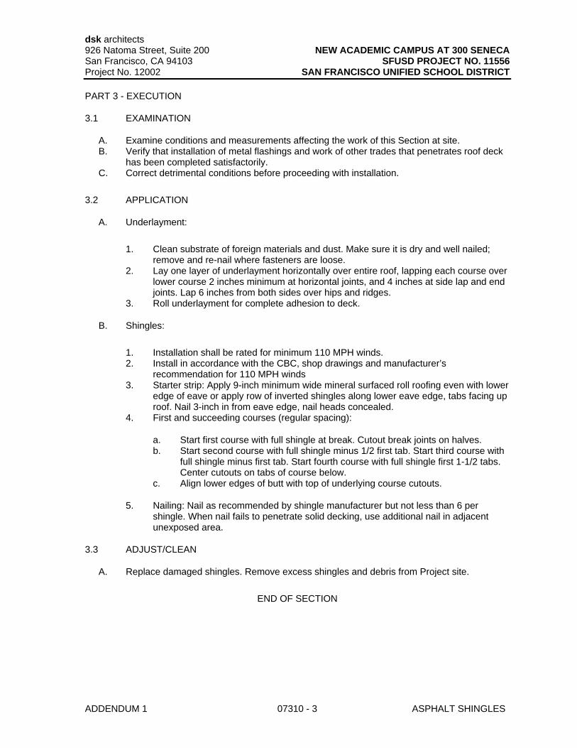
dsk architects 926 Natoma Street, Suite 200 NEW ACADEMIC CAMPUS AT 300 SENECA San Francisco, CA 94103 SFUSD PROJECT NO. 11556 Project No. 12002 SAN FRANCISCO UNIFIED SCHOOL DISTRICT
ADDENDUM 1 07310 - 3 ASPHALT SHINGLES
PART 3 - EXECUTION
3.1 EXAMINATION
A. Examine conditions and measurements affecting the work of this Section at site. B. Verify that installation of metal flashings and work of other trades that penetrates roof deck
has been completed satisfactorily. C. Correct detrimental conditions before proceeding with installation.
3.2 APPLICATION
A. Underlayment:
1. Clean substrate of foreign materials and dust. Make sure it is dry and well nailed; remove and re-nail where fasteners are loose.
2. Lay one layer of underlayment horizontally over entire roof, lapping each course over lower course 2 inches minimum at horizontal joints, and 4 inches at side lap and end joints. Lap 6 inches from both sides over hips and ridges.
3. Roll underlayment for complete adhesion to deck.
B. Shingles:
1. Installation shall be rated for minimum 110 MPH winds. 2. Install in accordance with the CBC, shop drawings and manufacturer’s
recommendation for 110 MPH winds 3. Starter strip: Apply 9-inch minimum wide mineral surfaced roll roofing even with lower
edge of eave or apply row of inverted shingles along lower eave edge, tabs facing up roof. Nail 3-inch in from eave edge, nail heads concealed.
4. First and succeeding courses (regular spacing):
a. Start first course with full shingle at break. Cutout break joints on halves. b. Start second course with full shingle minus 1/2 first tab. Start third course with
full shingle minus first tab. Start fourth course with full shingle first 1-1/2 tabs. Center cutouts on tabs of course below.
c. Align lower edges of butt with top of underlying course cutouts.
5. Nailing: Nail as recommended by shingle manufacturer but not less than 6 per shingle. When nail fails to penetrate solid decking, use additional nail in adjacent unexposed area.
3.3 ADJUST/CLEAN
A. Replace damaged shingles. Remove excess shingles and debris from Project site.
END OF SECTION
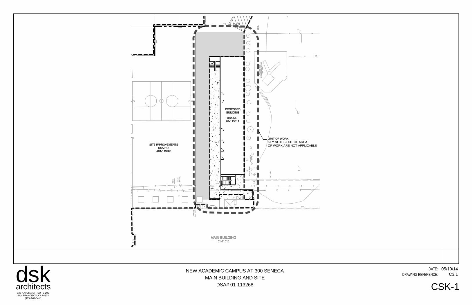
dskarchitects926 NATOMA ST. SUITE 200SAN FRANCISCO, CA 94103
(415) 849-6418
DRAWING REFERENCE:DATE:NEW ACADEMIC CAMPUS AT 300 SENECA
MAIN BUILDING AND SITE
DSA# 01-113268 CSK1
05/19/14C3.1
KEY NOTES OUT OF AREAOF WORK ARE NOT APPLICABLE
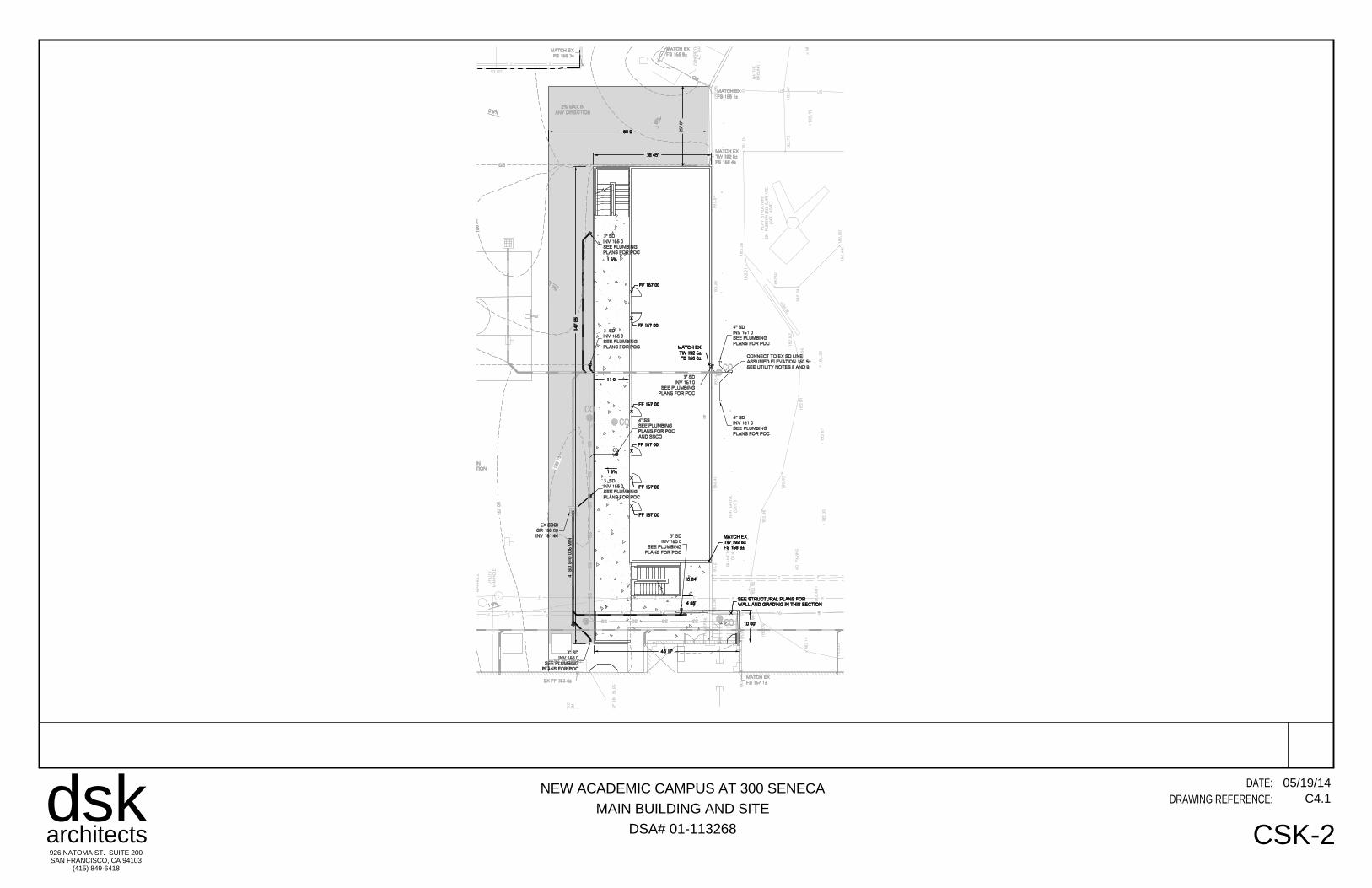
dskarchitects926 NATOMA ST. SUITE 200SAN FRANCISCO, CA 94103
(415) 849-6418
DRAWING REFERENCE:DATE:NEW ACADEMIC CAMPUS AT 300 SENECA
MAIN BUILDING AND SITE
DSA# 01-113268 CSK2
05/19/14C4.1
25'-0
"
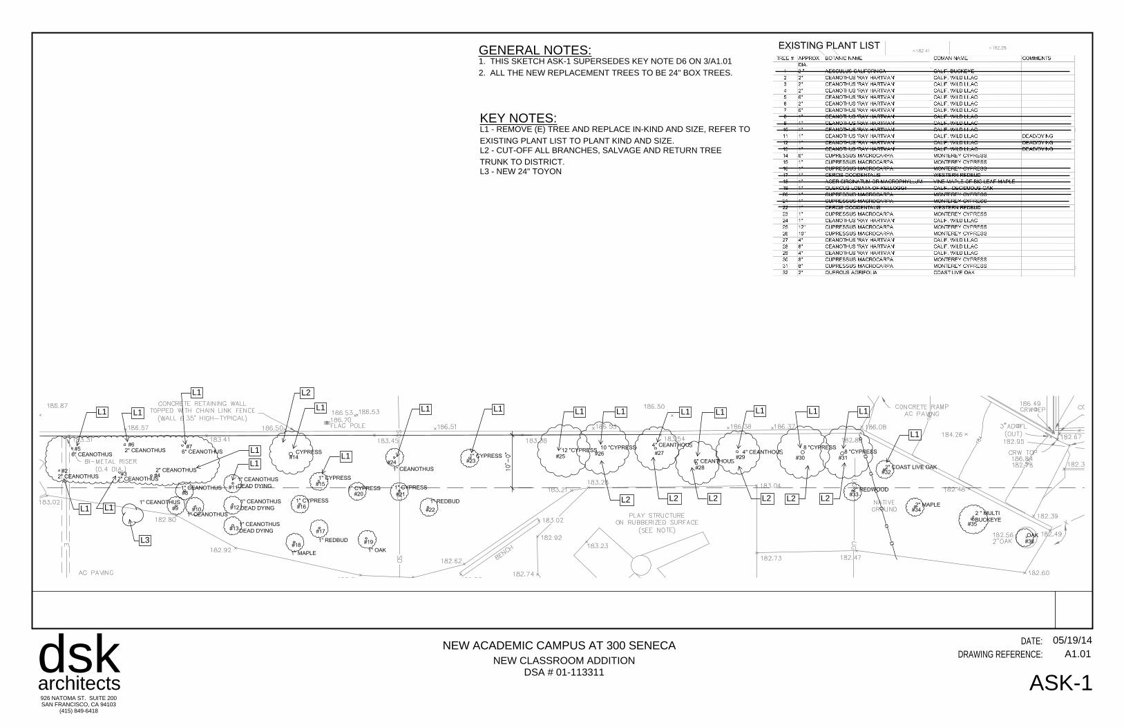
dskarchitects926 NATOMA ST. SUITE 200SAN FRANCISCO, CA 94103
(415) 849-6418
DRAWING REFERENCE:DATE:NEW ACADEMIC CAMPUS AT 300 SENECA
MAIN BUILDING AND SITE
DSA# 01-113268 ASK-4.0
01/17/14Y-A2.04NEW CLASSROOM ADDITION
DSA # 01113311
05/19/14A1.01
ASK1
GENERAL NOTES:1. THIS SKETCH ASK1 SUPERSEDES KEY NOTE D6 ON 3/A1.012. ALL THE NEW REPLACEMENT TREES TO BE 24" BOX TREES.
KEY NOTES:L1 REMOVE (E) TREE AND REPLACE INKIND AND SIZE, REFER TOEXISTING PLANT LIST TO PLANT KIND AND SIZE.L2 CUTOFF ALL BRANCHES, SALVAGE AND RETURN TREETRUNK TO DISTRICT.L3 NEW 24" TOYON
L1 L1
L1
L1
L1
L1
L1 L1 L1 L1 L1 L1 L1 L1 L1
L1
L1 L1
L1
L1 L1 L1 L1 L1 L1 L1
L2
L2 L2 L2 L2 L2 L2
L3
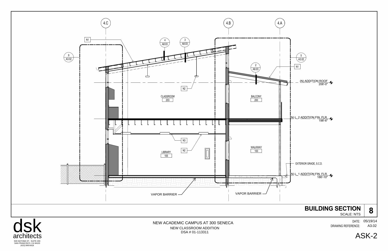
dskarchitects926 NATOMA ST. SUITE 200SAN FRANCISCO, CA 94103
(415) 849-6418
DRAWING REFERENCE:DATE:NEW ACADEMIC CAMPUS AT 300 SENECA
MAIN BUILDING AND SITE
DSA# 01-113268 ASK-4.0
01/17/14Y-A2.04NEW CLASSROOM ADDITION
DSA # 01113311
05/19/14A3.02
ASK2
(N) L_2 ADDITION FIN. FLR.198'-6"
(N) L_1 ADDITION FIN. FLR.186'-10"
A3.02
5
(N) ADDITION ROOF206'-0"
4.A4.B4.C
A3.02
9
4
A8.03
2
A8.03
3
A8.03
N1
N1
N2
N2
CLASSROOM
203
LIBRARY
105
BALCONY
200
WALKWAY
100
EXTERIOR GRADE, S.C.D.
N3
VAPOR BARRIERVAPOR BARRIER
BUILDING SECTION 8SCALE: NTS
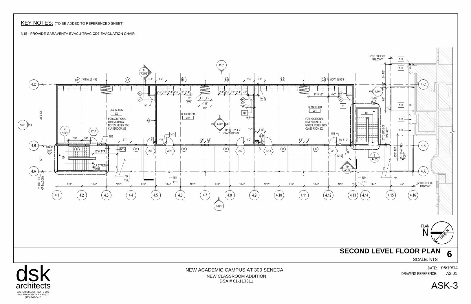
dskarchitects926 NATOMA ST. SUITE 200SAN FRANCISCO, CA 94103
(415) 849-6418
DRAWING REFERENCE:DATE:NEW ACADEMIC CAMPUS AT 300 SENECA
MAIN BUILDING AND SITE
DSA# 01-113268 ASK-4.0
01/17/14Y-A2.04NEW CLASSROOM ADDITION
DSA # 01113311
05/19/14A2.01
ASK3
SCALE: NTS
SECOND LEVEL FLOOR PLAN 6
A3.01
8
A3.02
A3.01
7
8
A3.01 14
4.A4.A
4.B4.B
4.C4.C
4.1 4.2 4.3 4.4 4.5 4.6 4.7 4.8 4.9 4.10 4.11 4.12 4.13 4.14 4.15 4.16
201201.1202202.1203
203.1
CLASSROOM
203 CLASSROOM
202
CLASSROOM
201
10'-7
"25
'-3 1
/2"
9'-2"14'-6"1'-1"10'-2"10'-2"10'-2"10'-2"10'-2"10'-2"10'-2"10'-2"10'-2"10'-2"10'-2"10'-2"
9'-8
"1'
-3 1
/2"
8'-4
1/2
"
UP
DN
STAIR
AA2
STAIR
BB2
N1
N1
N1
A4.02
7
8
610
A3.016
3'-6"5" 4'-0" 4'-0"
BB
1'-6" 6'-6 1/2"
C
1'-6"
C C
1'-6" 1'-6"5'-1"
C
5'-6"
WDW. @ HSSD.1WDW. @ HSSD.1 4'-3"4'-3" 4'-3"4'-3" E.1E.1E.1E.1
A4.05
3
A4.04
3
A2
A1
A1
A1
A1A1A1
A2
E1E1
2'-10"1'-2"
1'-2
"
TYP.
N2
TYP.
4'-11"
EQ. EQ.
TYP
.
4'-6
"
TYP.3'-0"
19
A3.02
N10
N11
N10
N11
N11
10'-0" TYP.
C.J. STARTINGPOINT
10'-0
" TY
P.
EQ
.
TYP.
N9 N9
C.J
. STA
RTI
NG
PO
INT
FOR ADDITIONALDIMENSIONS &NOTES, REFER TOOCLASSROOM 202
FOR ADDITIONALDIMENSIONS &NOTES, REFER TOOCLASSROOM 202
2'-4" 2'-4" 2'-4" 2'-4" 2'-4" 2'-4" 2'-4" 2'-4" 2'-4" 2'-4" 2'-4"
OF
BA
LCO
NY
5" T
O E
DG
E
BALCONY5" TO EDGE OF
BA
LCO
NY
6" T
O E
DG
E O
F
BALCONY5" TO EDGE OF
N13N13 N13
TYP.
N14
TYP. @ LEVEL 2CLASSROOMS
4'-0"7'-10 1/2"
TYP.
N14
N
TRUE
N
PLAN
N15
N15
KEY NOTES: (TO BE ADDED TO REFERENCED SHEET)
N15 PROVIDE GARAVENTA EVACUTRAC CD7 EVACUATION CHAIR
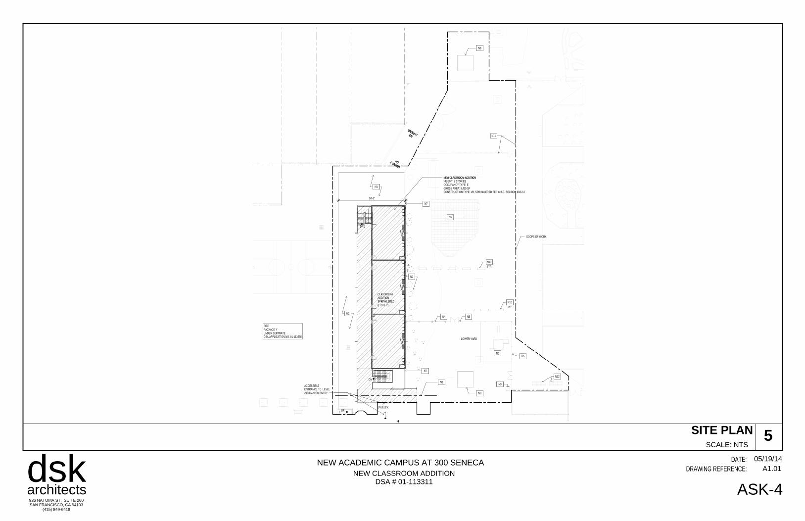
dskarchitects926 NATOMA ST. SUITE 200SAN FRANCISCO, CA 94103
(415) 849-6418
DRAWING REFERENCE:DATE:NEW ACADEMIC CAMPUS AT 300 SENECA
MAIN BUILDING AND SITE
DSA# 01-113268 ASK-4.0
01/17/14Y-A2.04NEW CLASSROOM ADDITION
DSA # 01113311
05/19/14A1.01
ASK4
SCALE: NTS
SITE PLAN 5
NOPARKING
NO PARKING
UP(N) ELEV.
ACCESSIBLEENTRANCE TO LEVEL2 ELEVATOR ENTRY
CLASSROOMADDITIONSPRINKLERED(LEVEL 2)
DN
DN
NEW CLASSROOM ADDITIONHEIGHT: 2 STORIESOCCUPANCY TYPE: EGROSS AREA: 9,425 SFCONSTRUCTION TYPE: VB, SPRINKLERED PER C.B.C. SECTION 903.2.3
NOPARKING
NO PARKING
SITEPACKAGE YUNDER SEPARATEDSA APPLICATION NO. 01-113268
N2
N1
LOWER YARD
N3
N4 N5
N5
N6
N6
N7
N7
N8
N8
N9
TYP.
N10
TYP.
N10
N11
N12
N1
50'-0"
SCOPE OF WORK
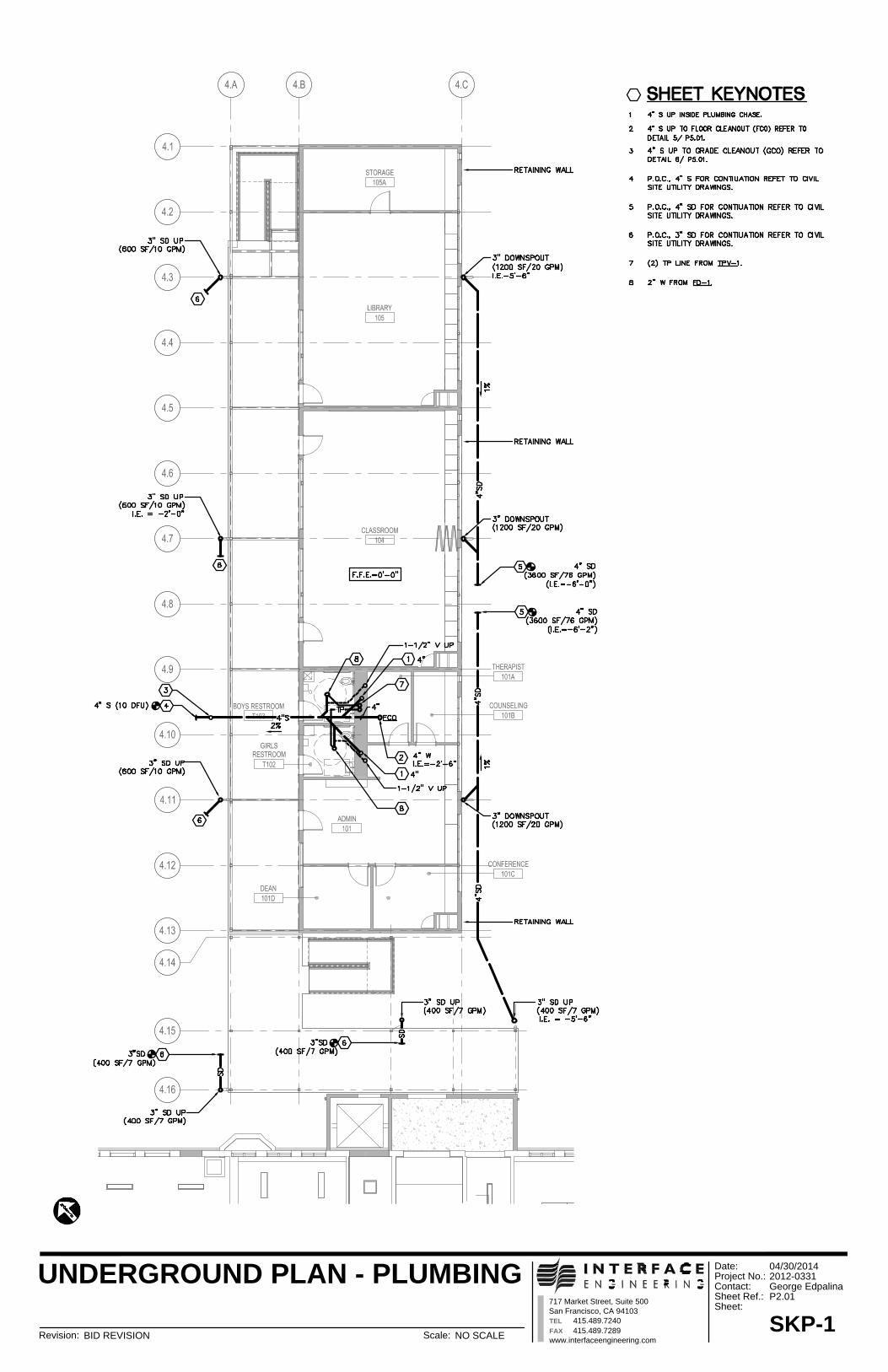
717 Market Street, Suite 500
San Francisco, CA 94103
TEL 415.489.7240
FAX 415.489.7289
www.interfaceengineering.com
Date:
Project No.:
Contact:
Sheet Ref.:
Sheet:
Revision: Scale:
UNDERGROUND PLAN - PLUMBING
04/30/2014
2012-0331
George Edpalina
P2.01
SKP-1
BID REVISION NO SCALE
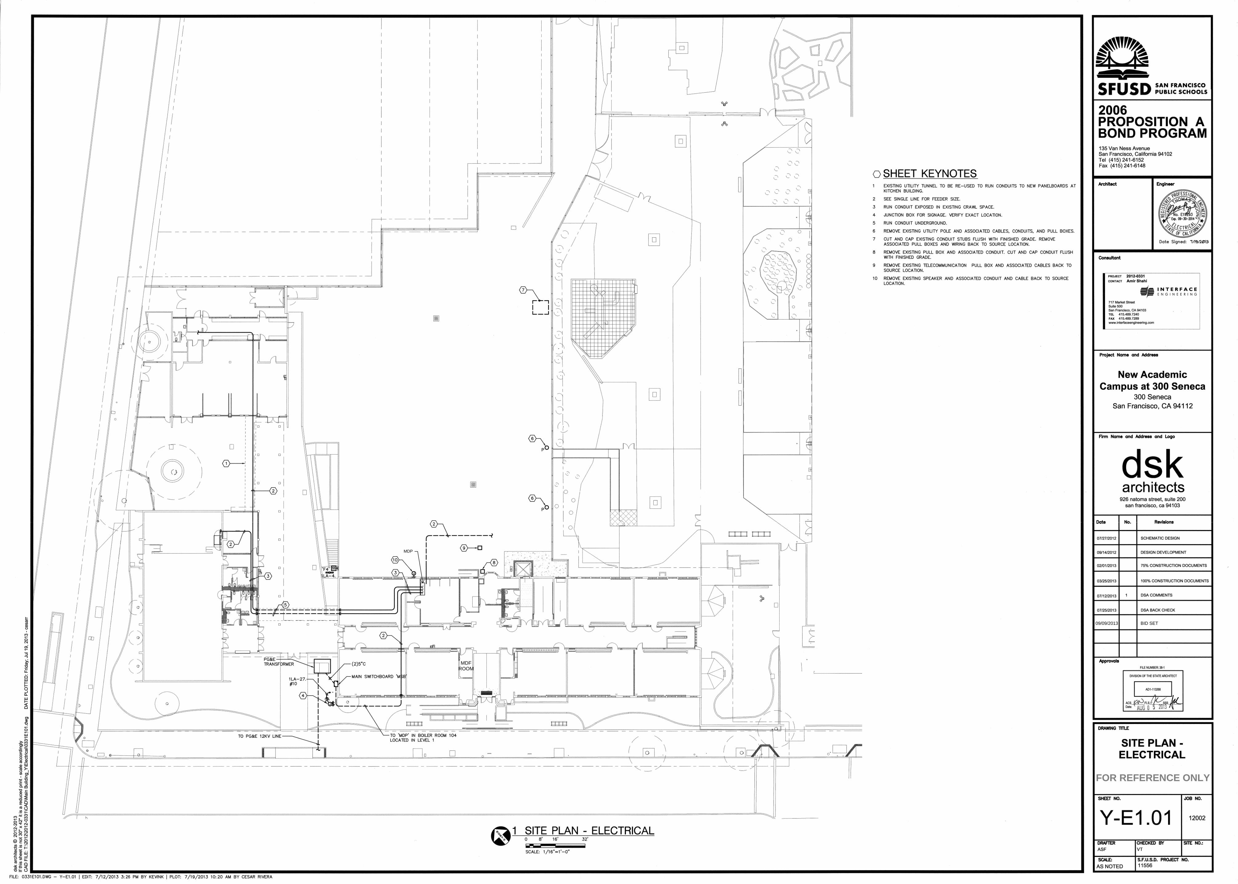
09/09/2013 BID SET
FOR REFERENCE ONLY
MDP
MDFROOM