pvc-u / pvc-c / pp-h / pvdf / abs - sed flowcontrol · pvc-u / pvc-c / pp-h / pvdf / abs catalog...
TRANSCRIPT
Manual Diaphragm Valve DN 15-100PVC-U / PVC-C / PP-H / PVDF / ABS
CATALOG
SMART IN FLOW CONTROL.
TABLE OF CONTENTS
Type 286 - DN 12-15 (MA 10) 04
General information - Technical specification 04
Sectional view 05
Technical data 06
Dimensions 07 - 09
Exploded view - Components - Part list 10
Assembly - Disassembly - Installation 11
Type 882 - DN 15-65 (MA 20-50) 12
General information - Technical specification 12
Sectional view 13
Technical data 14 - 15
Dimensions 16 - 20
Accessories 20
Fastening - Supporting - Customization 21
Exploded view - Components - Part list 22
Assembly - Disassembly - Installation 23 - 24
Adjustment 25
Type 885 - DN 80-100 (MA 80-100) 26
General information - Technical specification 26
Sectional view 27
Technical data 28
Dimensions 29 - 30
Exploded view - Components - Part list 31
Assembly - Disassembly - Installation 32
Ordering key 33
Overview product range 34
2
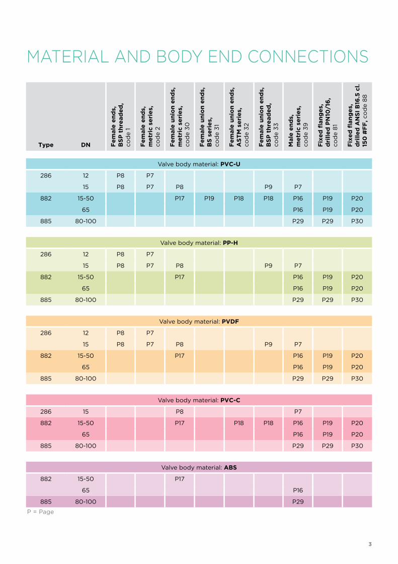
MATERIAL AND BODY END CONNECTIONS
Type DN Fe
male
en
ds,
BS
P t
hre
ad
ed
,co
de 1
Fe
male
en
ds,
me
tric
se
rie
s,co
de 2
Fe
male
un
ion
en
ds,
me
tric
se
rie
s,co
de 3
0
Fe
male
un
ion
en
ds,
BS
se
rie
s,co
de 3
1
Fe
male
un
ion
en
ds,
AS
TM
se
rie
s,co
de 3
2
Fe
male
un
ion
en
ds,
BS
P t
hre
ad
ed
,co
de 3
3
Male
en
ds,
me
tric
se
rie
s,co
de 3
9
Fix
ed
flan
ge
s,d
rill
ed
PN
10/1
6,
co
de 8
1
Fix
ed
flan
ge
s,d
rill
ed
AN
SI
B16
.5 c
l.15
0 #
FF
, co
de 8
8
Valve body material: PVC-U
286 12 P8 P7
15 P8 P7 P8 P9 P7
882 15-50 P17 P19 P18 P18 P16 P19 P20
65 P16 P19 P20
885 80-100 P29 P29 P30
Valve body material: PP-H
286 12 P8 P7
15 P8 P7 P8 P9 P7
882 15-50 P17 P16 P19 P20
65 P16 P19 P20
885 80-100 P29 P29 P30
Valve body material: PVDF
286 12 P8 P7
15 P8 P7 P8 P9 P7
882 15-50 P17 P16 P19 P20
65 P16 P19 P20
885 80-100 P29 P29 P30
Valve body material: PVC-C
286 15 P8 P7
882 15-50 P17 P18 P18 P16 P19 P20
65 P16 P19 P20
885 80-100 P29 P29 P30
Valve body material: ABS
882 15-50 P17
65 P16
885 80-100 P29
P = Page
3
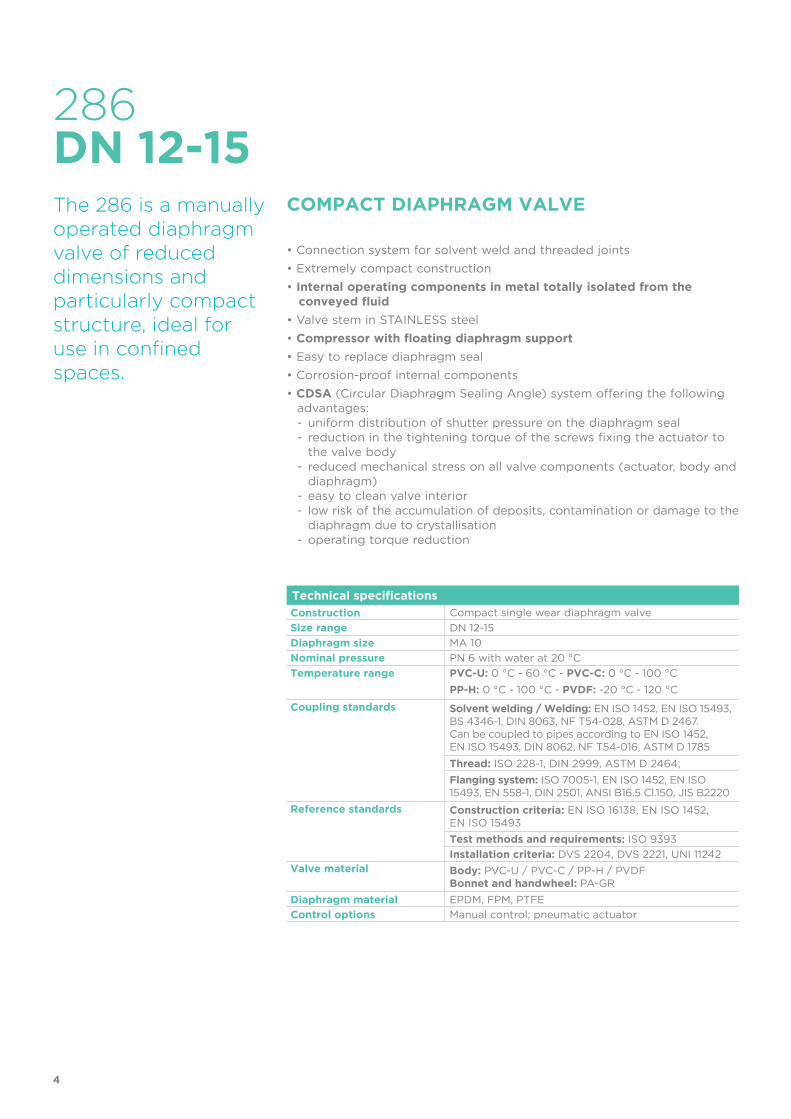
286
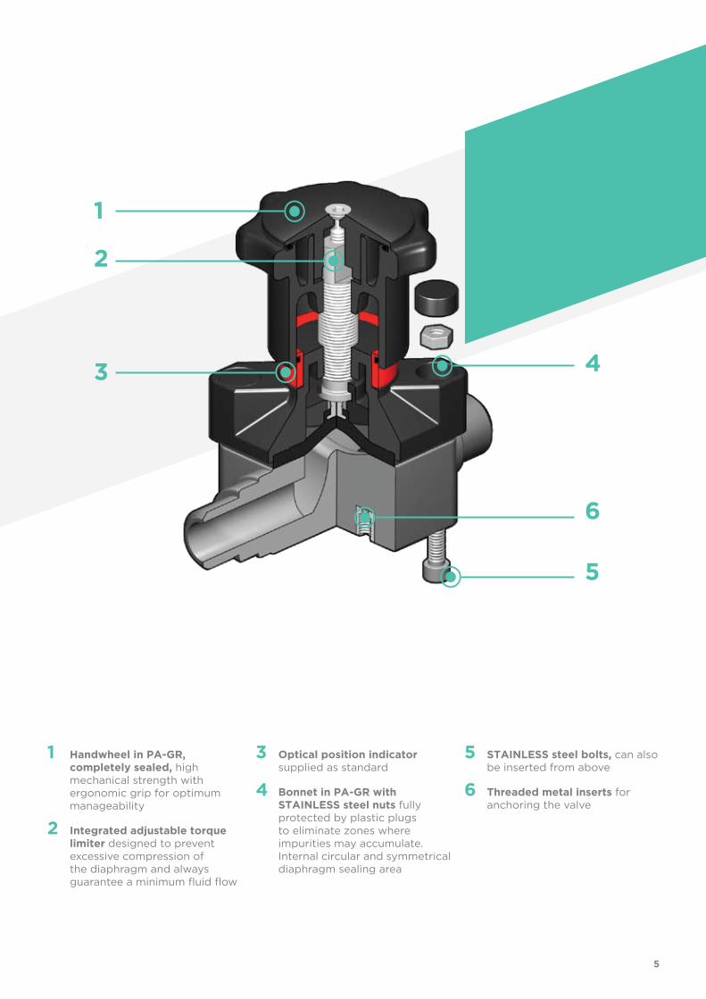
The 286 is a manually operated diaphragm valve of reduced dimensions and particularly compact structure, ideal for use in confined spaces.
COMPACT DIAPHRAGM VALVE
• Connection system for solvent weld and threaded joints
• Extremely compact construction
• Internal operating components in metal totally isolated from the conveyed fluid
• Valve stem in STAINLESS steel
• Compressor with floating diaphragm support
• Easy to replace diaphragm seal
• Corrosion-proof internal components
• CDSA (Circular Diaphragm Sealing Angle) system offering the following advantages:- uniform distribution of shutter pressure on the diaphragm seal- reduction in the tightening torque of the screws fixing the actuator to
the valve body- reduced mechanical stress on all valve components (actuator, body and
diaphragm)- easy to clean valve interior- low risk of the accumulation of deposits, contamination or damage to the
diaphragm due to crystallisation- operating torque reduction
DN 12-15
Technical specifications
Construction Compact single wear diaphragm valve
Size range DN 12-15
Diaphragm size MA 10
Nominal pressure PN 6 with water at 20 °C
Temperature range PVC-U: 0 °C - 60 °C - PVC-C: 0 °C - 100 °C
PP-H: 0 °C - 100 °C - PVDF: -20 °C - 120 °C
Coupling standards Solvent welding / Welding: EN ISO 1452, EN ISO 15493, BS 4346-1, DIN 8063, NF T54-028, ASTM D 2467. Can be coupled to pipes according to EN ISO 1452,EN ISO 15493, DIN 8062, NF T54-016, ASTM D 1785
Thread: ISO 228-1, DIN 2999, ASTM D 2464,
Flanging system: ISO 7005-1, EN ISO 1452, EN ISO 15493, EN 558-1, DIN 2501, ANSI B16.5 Cl.150, JIS B2220
Reference standards Construction criteria: EN ISO 16138, EN ISO 1452, EN ISO 15493
Test methods and requirements: ISO 9393
Installation criteria: DVS 2204, DVS 2221, UNI 11242Valve material Body: PVC-U / PVC-C / PP-H / PVDF
Bonnet and handwheel: PA-GR
Diaphragm material EPDM, FPM, PTFE
Control options Manual control; pneumatic actuator
4
1
2
3
6
5
4
1 Handwheel in PA-GR, completely sealed, high mechanical strength with ergonomic grip for optimum manageability
2 Integrated adjustable torque limiter designed to prevent excessive compression of the diaphragm and always guarantee a minimum fluid flow
3 Optical position indicator supplied as standard
4 Bonnet in PA-GR with STAINLESS steel nuts fully protected by plastic plugs to eliminate zones where impurities may accumulate. Internal circular and symmetrical diaphragm sealing area
5 STAINLESS steel bolts, can also be inserted from above
6 Threaded metal inserts for anchoring the valve
5
TECHNICAL DATA
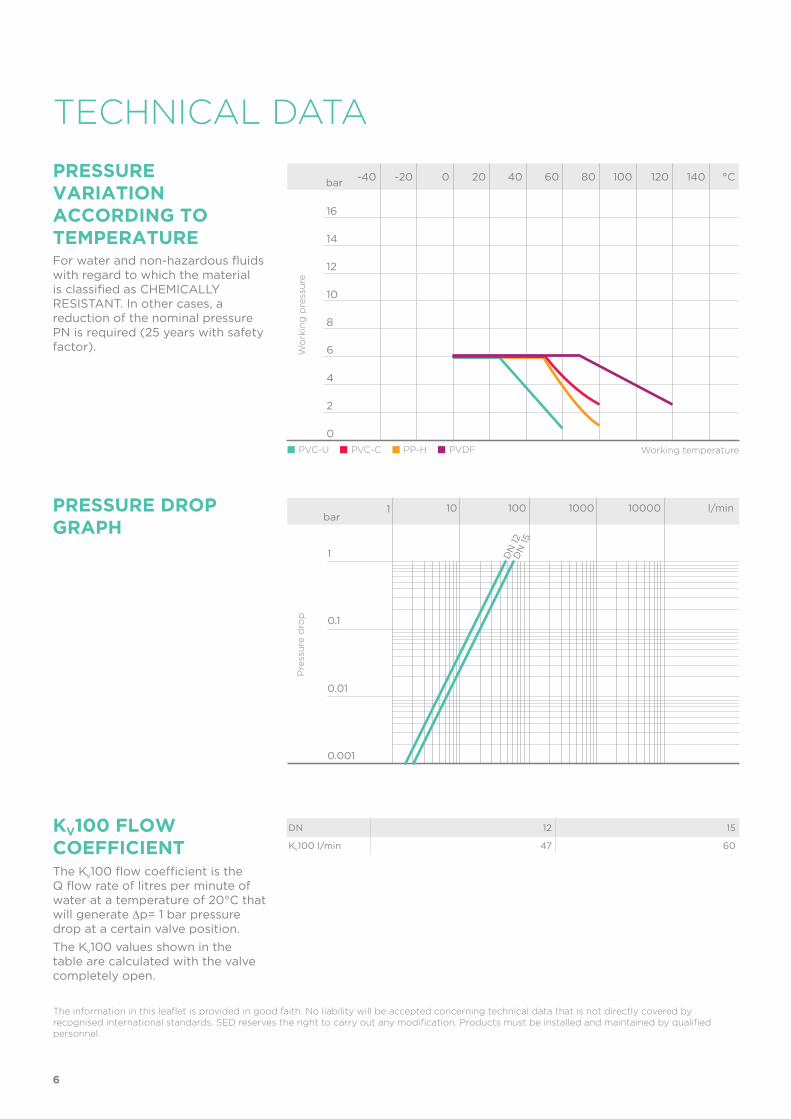
PRESSURE VARIATION ACCORDING TO TEMPERATUREFor water and non-hazardous fluids with regard to which the material is classified as CHEMICALLY RESISTANT. In other cases, a reduction of the nominal pressure PN is required (25 years with safety factor).
KV100 FLoW COEFFICIENTThe Kv100 flow coefficient is the Q flow rate of litres per minute of water at a temperature of 20°C that will generate ∆p= 1 bar pressure drop at a certain valve position.
The Kv100 values shown in the table are calculated with the valve completely open.
The information in this leaflet is provided in good faith. No liability will be accepted concerning technical data that is not directly covered by recognised international standards. SED reserves the right to carry out any modification. Products must be installed and maintained by qualified personnel.
PRESSURE DROP GRAPH
-40 -20 0 20 40 60 80 100 120 140 °C
16
14
12
10
8
6
4
2
0
Wo
rkin
g p
ress
ure
Working temperature
bar
DN 12 15
Kv100 l/min 47 60
Pre
ssu
re d
rop
bar1 10 100 1000 10000 l/min
1
0.1
0.01
0.001
DN
12
DN
15
PVC-U PVC-C PP-H PVDF
6
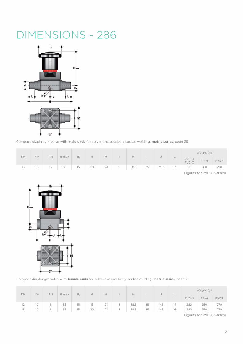
DIMENSIONS - 286
Compact diaphragm valve with male ends for solvent respectively socket welding, metric series, code 39
Compact diaphragm valve with female ends for solvent respectively socket welding, metric series, code 2
DN MA PN B max B1 d H h H1 I J L
Weight (g)
PVC-UPVC-C
PP-H PVDF
15 10 6 86 15 20 124 8 58.5 35 M5 17 310 260 290
DN MA PN B max B1 d H h H1 I J L
Weight (g)
PVC-U PP-H PVDF
12 10 6 86 15 16 124 8 58.5 35 M5 14 280 250 270
15 10 6 86 15 20 124 8 58.5 35 M5 16 280 250 270
Figures for PVC-U version
Figures for PVC-U version
7
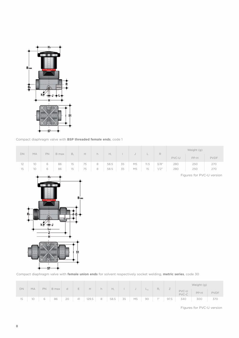
Compact diaphragm valve with BSP threaded female ends, code 1
Compact diaphragm valve with female union ends for solvent respectively socket welding, metric series, code 30
DN MA PN B max d E H h H1 I J LA R1 Z
Weight (g)
PVC-UPVC-C
PP-H PVDF
15 10 6 86 20 41 129.5 8 58.5 35 M5 90 1” 97.5 340 300 370
DN MA PN B max B1 H h H1 I J L R
Weight (g)
PVC-U PP-H PVDF
12 10 6 86 15 75 8 58.5 35 M5 11.5 3/8” 280 250 270
15 10 6 86 15 75 8 58.5 35 M5 15 1/2” 280 250 270
Figures for PVC-U version
Figures for PVC-U version
8
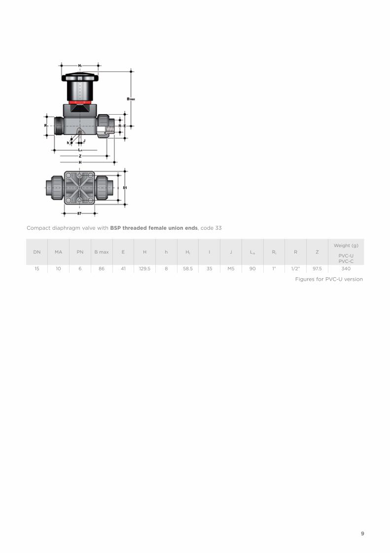
Compact diaphragm valve with BSP threaded female union ends, code 33
DN MA PN B max E H h H1 I J LA R1 R Z
Weight (g)
PVC-UPVC-C
15 10 6 86 41 129.5 8 58.5 35 M5 90 1” 1/2” 97.5 340
Figures for PVC-U version
9
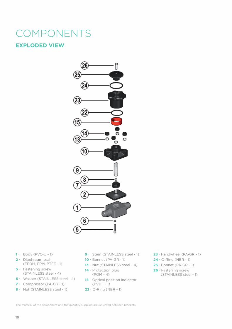
The material of the component and the quantity supplied are indicated between brackets
COMPONENTSEXPLoDED VIEW
1 Body (PVC-U - 1)
2 Diaphragm seal (EPDM, FPM, PTFE - 1)
5 Fastening screw (STAINLESS steel - 4)
6 Washer (STAINLESS steel - 4)
7 Compressor (PA-GR - 1)
8 Nut (STAINLESS steel - 1)
9 Stem (STAINLESS steel - 1)
10 Bonnet (PA-GR - 1)
13 Nut (STAINLESS steel - 4)
14 Protection plug (POM - 4)
15 Optical position indicator (PVDF - 1)
22 O-Ring (NBR - 1)
23 Handwheel (PA-GR - 1)
24 O-Ring (NBR - 1)
25 Bonnet (PA-GR - 1)
26 Fastening screw (STAINLESS steel - 1)
10
DISMOUNTING MOUNTINGIf the valve is already installed on the line, shut-off the fluid flow upstream and make sure that there is no pressure. If necessary, fully drain the system downstream. If there are hazardous fluids present, drain and ventilate the valve.
The diaphragm constitutes the part of the valve more subject to mechanical and chemical stress from the fluid. Consequently, the condition of the diaphragm must be checked at regular intervals in accordance with the service conditions. To do this, it must be disconnected from the handwheel and from the valve body.
1) Unscrew the four screws (5) and separate the body (1) from the internal components.
2) Unscrew the diaphragm seal (2) from the shutter (7).
3) If necessary, clean or replace the diaphragm seal (2).
4) If necessary, lubricate the stem (9).
1) The diaphragm seal (2) must be screwed fully into the compressor (7) in a clockwise direction. If necessary, unscrew slightly in an anticlockwise direction to line up the screw holes.
2) Fix the bonnet (10) to the body (1) using screws (5). Tighten the screws, making sure not to over-compress the diaphragm.
INSTALLATIONThe valve can be installed in any position and in any direction.When starting up the plant, make sure that there are no leaks from between the diaphragm and the valve body. If necessary, tighten the fastening screws (5).
SETTING
The valve is factory set to guarantee a permanent seal without requiring any further intervention. To adjust the setting, rotate the handwheel to the required minimum opening position, remove screw (26) using a hex key.
Remove the bonnet (25) and rotate the handwheel (23) clockwise until a resistance to the rotation is felt.
If necessary, replace the O-Ring (24) in its seating and re-insert the bonnet
(25) in the handwheel: the double D connection must fit over the stem (9) and, with a slight twisting action, align the ribs in the bonnet with those in the handwheel.
Tighten screw (26) to a sufficiently high torque value.
Each turn of the handwheel corresponds to 1.75mm travel.
11
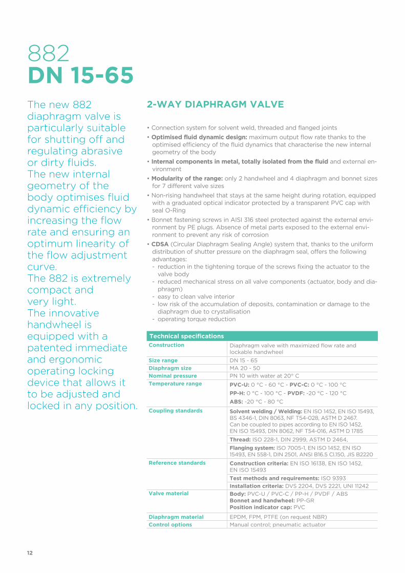
Technical specifications
Construction Diaphragm valve with maximized flow rate and lockable handwheel
Size range DN 15 - 65
Diaphragm size MA 20 - 50
Nominal pressure PN 10 with water at 20° C
Temperature range PVC-U: 0 °C - 60 °C - PVC-C: 0 °C - 100 °C
PP-H: 0 °C - 100 °C - PVDF: -20 °C - 120 °C
ABS: -20 °C - 80 °C
Coupling standards Solvent welding / Welding: EN ISO 1452, EN ISO 15493, BS 4346-1, DIN 8063, NF T54-028, ASTM D 2467. Can be coupled to pipes according to EN ISO 1452,EN ISO 15493, DIN 8062, NF T54-016, ASTM D 1785
Thread: ISO 228-1, DIN 2999, ASTM D 2464,
Flanging system: ISO 7005-1, EN ISO 1452, EN ISO 15493, EN 558-1, DIN 2501, ANSI B16.5 Cl.150, JIS B2220
Reference standards Construction criteria: EN ISO 16138, EN ISO 1452, EN ISO 15493
Test methods and requirements: ISO 9393
Installation criteria: DVS 2204, DVS 2221, UNI 11242Valve material Body: PVC-U / PVC-C / PP-H / PVDF / ABS
Bonnet and handwheel: PP-GRPosition indicator cap: PVC
Diaphragm material EPDM, FPM, PTFE (on request NBR)
Control options Manual control; pneumatic actuator
882
The new 882 diaphragm valve is particularly suitable for shutting off and regulating abrasive or dirty fluids. The new internal geometry of the body optimises fluid dynamic efficiency by increasing the flow rate and ensuring an optimum linearity of the flow adjustment curve. The 882 is extremely compact and very light. The innovative handwheel is equipped with a patented immediate and ergonomic operating locking device that allows it to be adjusted and locked in any position.
2-WAY DIAPHRAGM VALVE
• Connection system for solvent weld, threaded and flanged joints
• optimised fluid dynamic design: maximum output flow rate thanks to the optimised efficiency of the fluid dynamics that characterise the new internal geometry of the body
• Internal components in metal, totally isolated from the fluid and external en-vironment
• Modularity of the range: only 2 handwheel and 4 diaphragm and bonnet sizes for 7 different valve sizes
• Non-rising handwheel that stays at the same height during rotation, equipped with a graduated optical indicator protected by a transparent PVC cap with seal O-Ring
• Bonnet fastening screws in AISI 316 steel protected against the external envi-ronment by PE plugs. Absence of metal parts exposed to the external envi-ronment to prevent any risk of corrosion
• CDSA (Circular Diaphragm Sealing Angle) system that, thanks to the uniform distribution of shutter pressure on the diaphragm seal, offers the following advantages:- reduction in the tightening torque of the screws fixing the actuator to the
valve body- reduced mechanical stress on all valve components (actuator, body and dia-
phragm)- easy to clean valve interior- low risk of the accumulation of deposits, contamination or damage to the
diaphragm due to crystallisation- operating torque reduction
DN 15-65
12
3
4
7
12
6
8
5
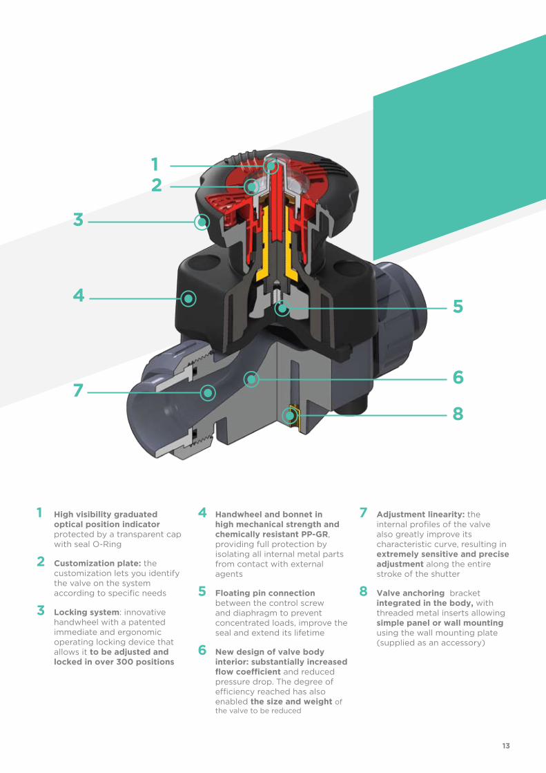
1 High visibility graduated optical position indicator protected by a transparent cap with seal O-Ring
2 Customization plate: the customization lets you identify the valve on the system according to specific needs
3 Locking system: innovative handwheel with a patented immediate and ergonomic operating locking device that allows it to be adjusted and locked in over 300 positions
4 Handwheel and bonnet in high mechanical strength and chemically resistant PP-GR, providing full protection by isolating all internal metal parts from contact with external agents
5 Floating pin connection between the control screw and diaphragm to prevent concentrated loads, improve the seal and extend its lifetime
6 New design of valve body interior: substantially increased flow coefficient and reduced pressure drop. The degree of efficiency reached has also enabled the size and weight of the valve to be reduced
7 Adjustment linearity: the internal profiles of the valve also greatly improve its characteristic curve, resulting in extremely sensitive and precise adjustment along the entire stroke of the shutter
8 Valve anchoring bracket integrated in the body, with threaded metal inserts allowing simple panel or wall mounting using the wall mounting plate (supplied as an accessory)
13
TECHNICAL DATA
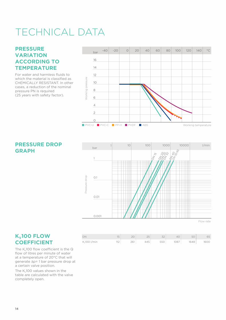
PRESSURE VARIATION ACCORDING TO TEMPERATUREFor water and harmless fluids to which the material is classified as CHEMICALLY RESISTANT. In other cases, a reduction of the nominal pressure PN is required (25 years with safety factor).
DN 15 20 25 32 40 50 65
Kv100 l/min 112 261 445 550 1087 1648 1600
KV100 FLoW COEFFICIENTThe Kv100 flow coefficient is the Q flow of litres per minute of water at a temperature of 20°C that will generate ∆p= 1 bar pressure drop at a certain valve position.
The Kv100 values shown in the table are calculated with the valve completely open.
Flow rate
PRESSURE DROP GRAPH
Pre
ssu
re d
rop
bar1 10 100 1000 10000 l/min
1
0.1
0.01
0.001
DN
15
DN
20
DN
25
DN
32
DN
40
DN
50
-65
-40 -20 0 20 40 60 80 100 120 140 °C
16
14
12
10
8
6
4
2
0
Wo
rkin
g p
ress
ure
Working temperature
bar
PVC-U PVC-C PP-H PVDF ABS
14
5 10 15 20 25 30 35 40 45 50 55 60 65 70 75 80 85 90 100 %
100
90
80
70
60
50
40
30
20
10
0
%
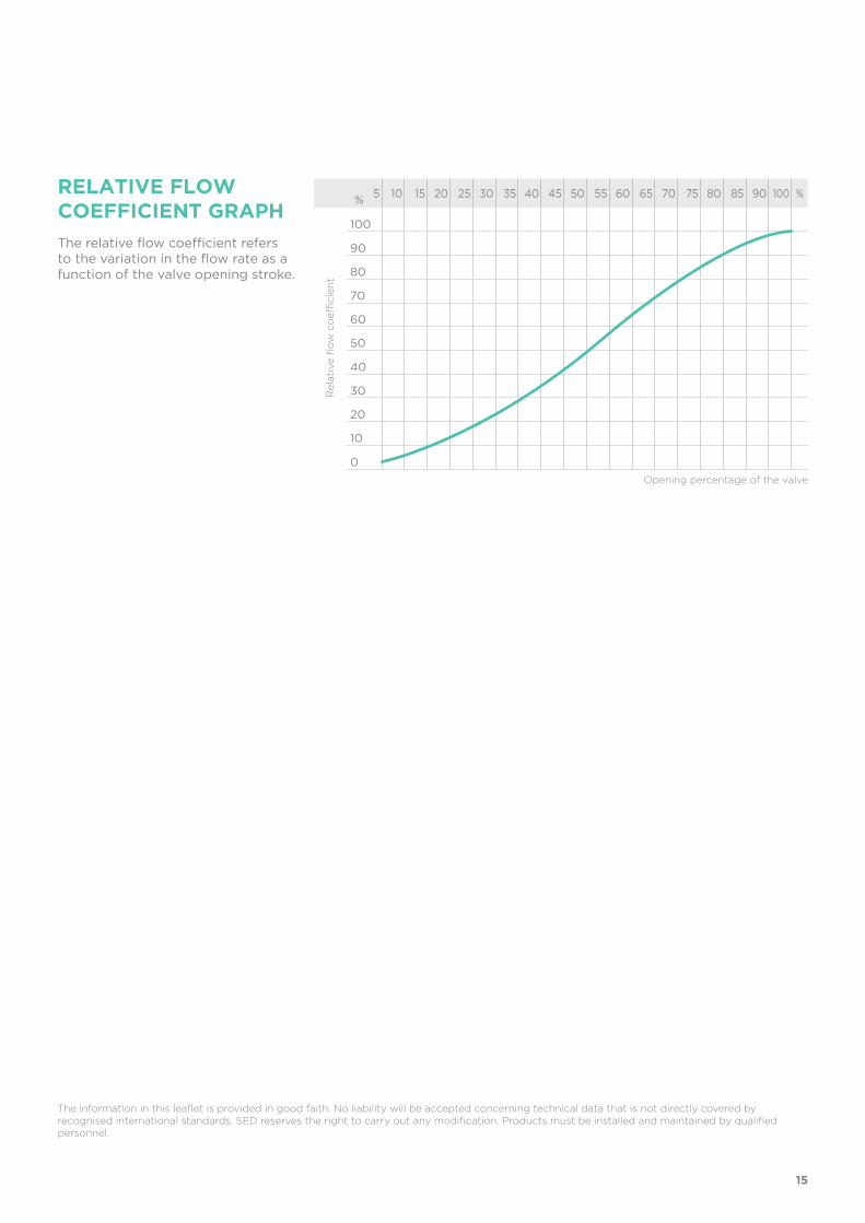
The relative flow coefficient refers to the variation in the flow rate as a function of the valve opening stroke.
The information in this leaflet is provided in good faith. No liability will be accepted concerning technical data that is not directly covered by recognised international standards. SED reserves the right to carry out any modification. Products must be installed and maintained by qualified personnel.
RELATIVE FLoW COEFFICIENT GRAPH
Rela
tive fl
ow
co
effi
cie
nt
Opening percentage of the valve
15
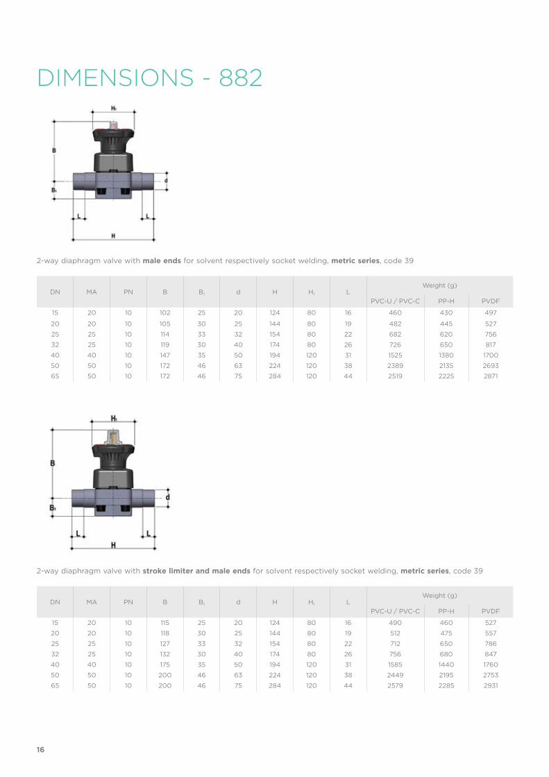
DIMENSIONS - 882
DN MA PN B B1 d H H1 LWeight (g)
PVC-U / PVC-C PP-H PVDF
15 20 10 102 25 20 124 80 16 460 430 497
20 20 10 105 30 25 144 80 19 482 445 527
25 25 10 114 33 32 154 80 22 682 620 756
32 25 10 119 30 40 174 80 26 726 650 817
40 40 10 147 35 50 194 120 31 1525 1380 1700
50 50 10 172 46 63 224 120 38 2389 2135 2693
65 50 10 172 46 75 284 120 44 2519 2225 2871
2-way diaphragm valve with male ends for solvent respectively socket welding, metric series, code 39
DN MA PN B B1 d H H1 LWeight (g)
PVC-U / PVC-C PP-H PVDF
15 20 10 115 25 20 124 80 16 490 460 527
20 20 10 118 30 25 144 80 19 512 475 557
25 25 10 127 33 32 154 80 22 712 650 786
32 25 10 132 30 40 174 80 26 756 680 847
40 40 10 175 35 50 194 120 31 1585 1440 1760
50 50 10 200 46 63 224 120 38 2449 2195 2753
65 50 10 200 46 75 284 120 44 2579 2285 2931
2-way diaphragm valve with stroke limiter and male ends for solvent respectively socket welding, metric series, code 39
16
DN MA PN B B1 d E
H
H1 LA R1
Z Weight (g)
ABSPVC-UPVC-C
PP-HPVDF
ABSPVC-UPVC-C
PP-HPVDF
PVC-UPVC-C
PP-HABS
PVDF
15 20 10 102 25 20 41 129 128 80 90 1” 100 101 500 457 551
20 20 10 105 30 25 50 154 150 80 108 1” 1/4 116 119 562 500 636
25 25 10 114 33 32 58 168 163 80 116 1” 1/2 124 127 790 695 905
32 25 10 119 30 40 72 192 184 80 134 2” 140 145 916 781 1077
40 40 10 147 35 50 79 222 210 120 154 2” 1/4 160 165 1737 1526 1989
50 50 10 172 46 63 98 266 248 120 184 2” 3/4 190 195 2785 2410 3235
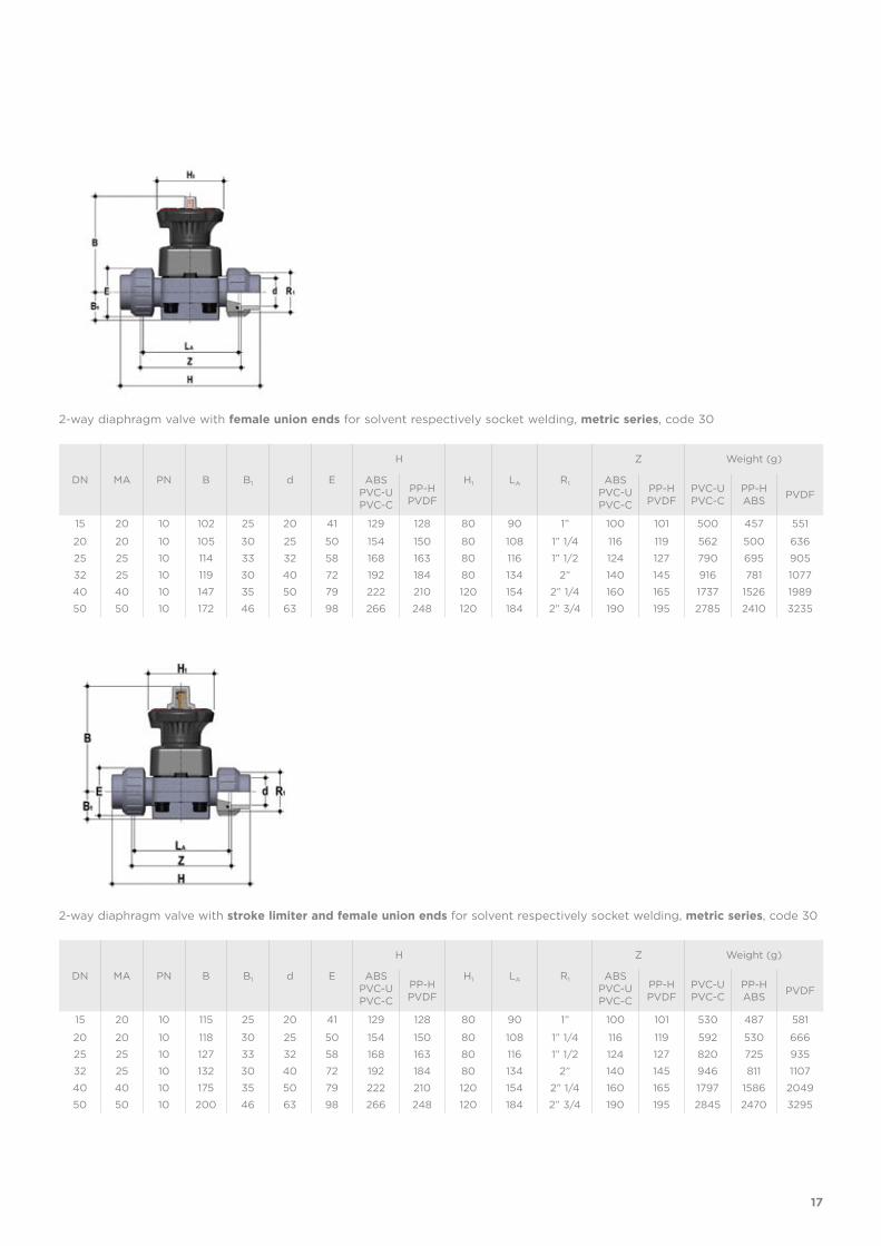
2-way diaphragm valve with female union ends for solvent respectively socket welding, metric series, code 30
2-way diaphragm valve with stroke limiter and female union ends for solvent respectively socket welding, metric series, code 30
DN MA PN B B1 d E
H
H1 LA R1
Z Weight (g)
ABSPVC-UPVC-C
PP-HPVDF
ABSPVC-UPVC-C
PP-HPVDF
PVC-UPVC-C
PP-HABS
PVDF
15 20 10 115 25 20 41 129 128 80 90 1” 100 101 530 487 581
20 20 10 118 30 25 50 154 150 80 108 1” 1/4 116 119 592 530 666
25 25 10 127 33 32 58 168 163 80 116 1” 1/2 124 127 820 725 935
32 25 10 132 30 40 72 192 184 80 134 2” 140 145 946 811 1107
40 40 10 175 35 50 79 222 210 120 154 2” 1/4 160 165 1797 1586 2049
50 50 10 200 46 63 98 266 248 120 184 2” 3/4 190 195 2845 2470 3295
17
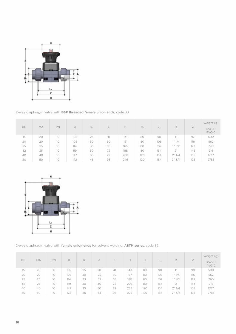
DN MA PN B B1 E H H1 LA R1 Z
Weight (g)
PVC-UPVC-C
15 20 10 102 25 41 131 80 90 1” 97 500
20 20 10 105 30 50 151 80 108 1” 1/4 118 562
25 25 10 114 33 58 165 80 116 1” 1/2 127 790
32 25 10 119 30 72 188 80 134 2” 145 916
40 40 10 147 35 79 208 120 154 2” 1/4 165 1737
50 50 10 172 46 98 246 120 184 2” 3/4 195 2785
DN MA PN B B1 d E H H1 LA R1 Z
Weight (g)
PVC-UPVC-C
15 20 10 102 25 20 41 143 80 90 1” 98 500
20 20 10 105 30 25 50 167 80 108 1” 1/4 115 562
25 25 10 114 33 32 58 180 80 116 1” 1/2 122 790
32 25 10 119 30 40 72 208 80 134 2 144 916
40 40 10 147 35 50 79 234 120 154 2” 1/4 164 1737
50 50 10 172 46 63 98 272 120 184 2” 3/4 195 2785
2-way diaphragm valve with BSP threaded female union ends, code 33
2-way diaphragm valve with female union ends for solvent welding, ASTM series, code 32
18
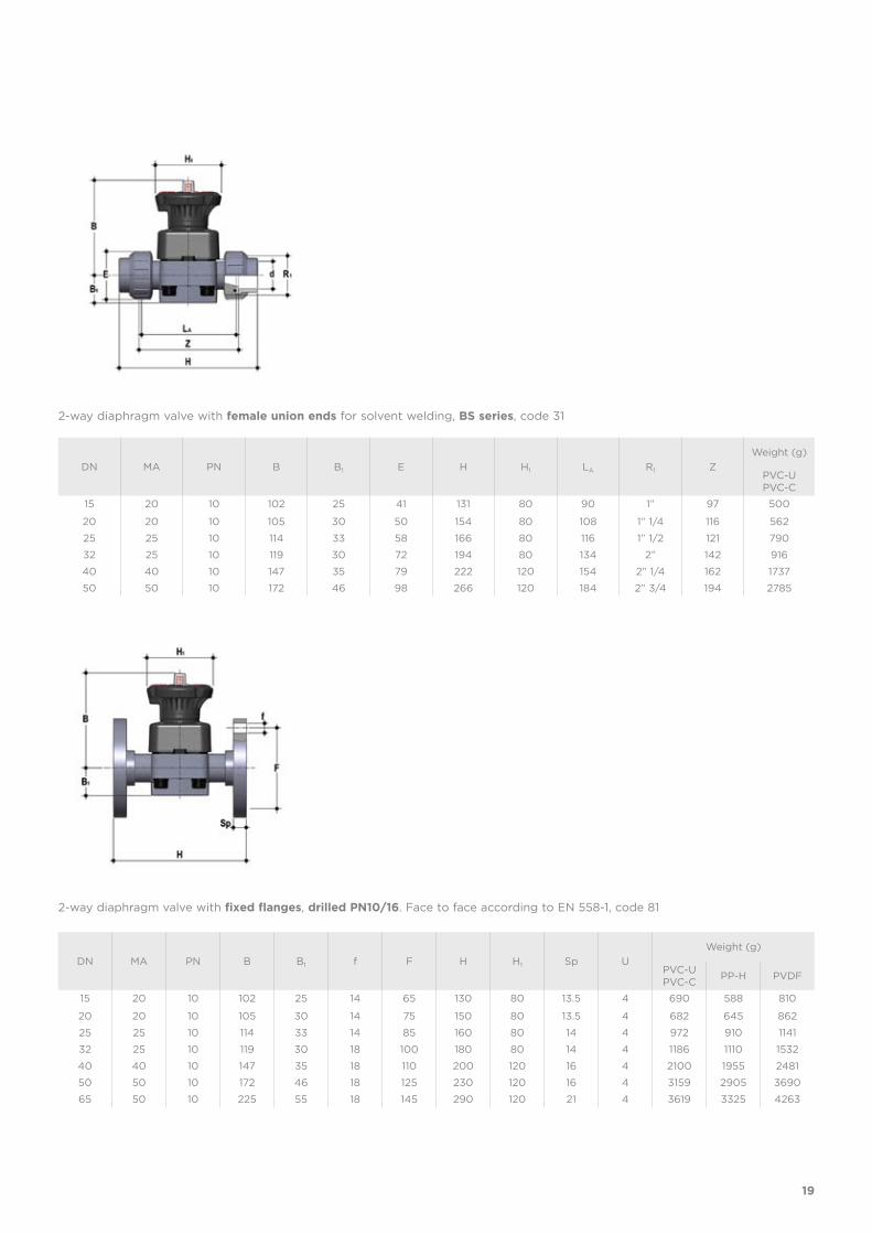
DN MA PN B B1 f F H H1 Sp U
Weight (g)
PVC-UPVC-C
PP-H PVDF
15 20 10 102 25 14 65 130 80 13.5 4 690 588 810
20 20 10 105 30 14 75 150 80 13.5 4 682 645 862
25 25 10 114 33 14 85 160 80 14 4 972 910 1141
32 25 10 119 30 18 100 180 80 14 4 1186 1110 1532
40 40 10 147 35 18 110 200 120 16 4 2100 1955 2481
50 50 10 172 46 18 125 230 120 16 4 3159 2905 3690
65 50 10 225 55 18 145 290 120 21 4 3619 3325 4263
DN MA PN B B1 E H H1 LA R1 Z
Weight (g)
PVC-UPVC-C
15 20 10 102 25 41 131 80 90 1” 97 500
20 20 10 105 30 50 154 80 108 1” 1/4 116 562
25 25 10 114 33 58 166 80 116 1” 1/2 121 790
32 25 10 119 30 72 194 80 134 2” 142 916
40 40 10 147 35 79 222 120 154 2” 1/4 162 1737
50 50 10 172 46 98 266 120 184 2” 3/4 194 2785
2-way diaphragm valve with female union ends for solvent welding, BS series, code 31
2-way diaphragm valve with fixed flanges, drilled PN10/16. Face to face according to EN 558-1, code 81
19
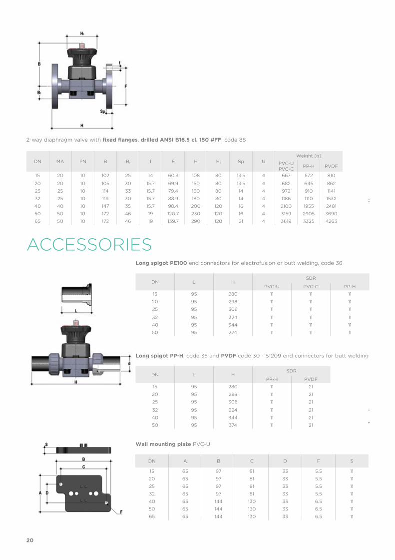
DN A B C D F S
15 65 97 81 33 5.5 11
20 65 97 81 33 5.5 11
25 65 97 81 33 5.5 11
32 65 97 81 33 5.5 11
40 65 144 130 33 6.5 11
50 65 144 130 33 6.5 11
65 65 144 130 33 6.5 11
ACCESSORIESLong spigot PE100 end connectors for electrofusion or butt welding, code 36
DN L HSDR
PVC-U PVC-C PP-H
15 95 280 11 11 11
20 95 298 11 11 11
25 95 306 11 11 11
32 95 324 11 11 11
40 95 344 11 11 11
50 95 374 11 11 11
DN MA PN B B1 f F H H1 Sp UWeight (g)
PVC-UPVC-C
PP-H PVDF
15 20 10 102 25 14 60.3 108 80 13.5 4 667 572 810
20 20 10 105 30 15.7 69.9 150 80 13.5 4 682 645 862
25 25 10 114 33 15.7 79.4 160 80 14 4 972 910 1141
32 25 10 119 30 15.7 88.9 180 80 14 4 1186 1110 1532
40 40 10 147 35 15.7 98.4 200 120 16 4 2100 1955 2481
50 50 10 172 46 19 120.7 230 120 16 4 3159 2905 3690
65 50 10 172 46 19 139.7 290 120 21 4 3619 3325 4263
2-way diaphragm valve with fixed flanges, drilled ANSI B16.5 cl. 150 #FF, code 88
Long spigot PP-H, code 35 and PVDF code 30 - S1209 end connectors for butt welding
Wall mounting plate PVC-U
DN L HSDR
PP-H PVDF
15 95 280 11 21
20 95 298 11 21
25 95 306 11 21
32 95 324 11 21
40 95 344 11 21
50 95 374 11 21
20
BC
A
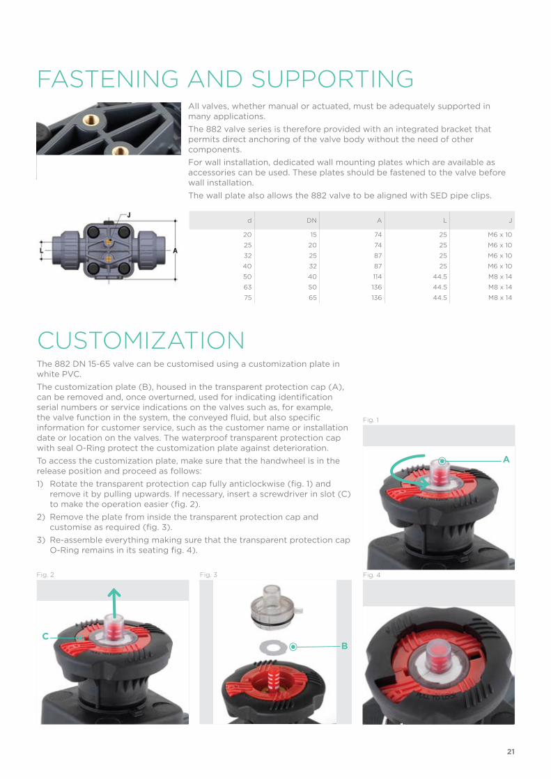
FASTENINg AND SUPPORTINgAll valves, whether manual or actuated, must be adequately supported in many applications.
The 882 valve series is therefore provided with an integrated bracket that permits direct anchoring of the valve body without the need of other components.
For wall installation, dedicated wall mounting plates which are available as accessories can be used. These plates should be fastened to the valve before wall installation.
The wall plate also allows the 882 valve to be aligned with SED pipe clips.
d DN A L J
20 15 74 25 M6 x 10
25 20 74 25 M6 x 10
32 25 87 25 M6 x 10
40 32 87 25 M6 x 10
50 40 114 44.5 M8 x 14
63 50 136 44.5 M8 x 14
75 65 136 44.5 M8 x 14
CUSTOMIzATIONThe 882 DN 15-65 valve can be customised using a customization plate in white PVC.
The customization plate (B), housed in the transparent protection cap (A), can be removed and, once overturned, used for indicating identification serial numbers or service indications on the valves such as, for example, the valve function in the system, the conveyed fluid, but also specific information for customer service, such as the customer name or installation date or location on the valves. The waterproof transparent protection cap with seal O-Ring protect the customization plate against deterioration.
To access the customization plate, make sure that the handwheel is in the release position and proceed as follows:
1) Rotate the transparent protection cap fully anticlockwise (fig. 1) and remove it by pulling upwards. If necessary, insert a screwdriver in slot (C) to make the operation easier (fig. 2).
2) Remove the plate from inside the transparent protection cap and customise as required (fig. 3).
3) Re-assemble everything making sure that the transparent protection cap O-Ring remains in its seating fig. 4).
Fig. 1
Fig. 2 Fig. 3 Fig. 4
21
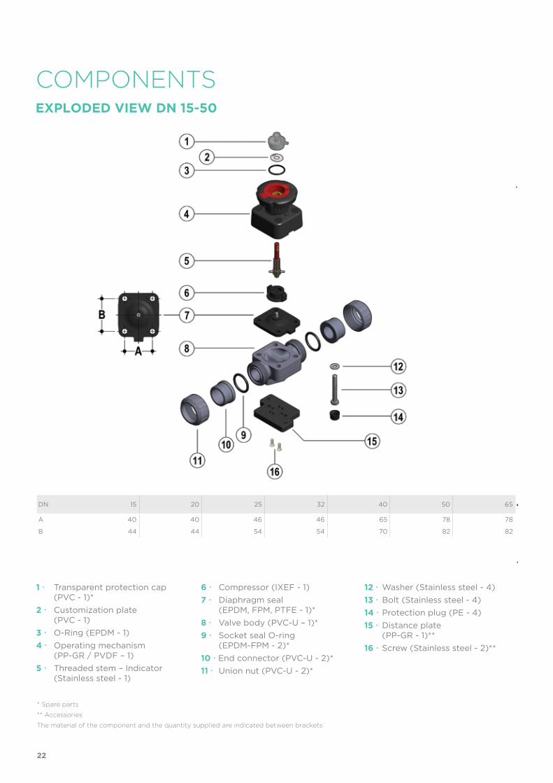
COMPONENTSEXPLoDED VIEW DN 15-50
DN 15 20 25 32 40 50 65
A 40 40 46 46 65 78 78
B 44 44 54 54 70 82 82
* Spare parts
** Accessories
The material of the component and the quantity supplied are indicated between brackets
1 Transparent protection cap (PVC - 1)*
2 Customization plate (PVC - 1)
3 O-Ring (EPDM - 1)
4 Operating mechanism (PP-GR / PVDF – 1)
5 Threaded stem – Indicator (Stainless steel - 1)
6 Compressor (IXEF - 1)
7 Diaphragm seal (EPDM, FPM, PTFE - 1)*
8 Valve body (PVC-U – 1)*
9 Socket seal O-ring (EPDM-FPM - 2)*
10 End connector (PVC-U - 2)*
11 Union nut (PVC-U - 2)*
12 Washer (Stainless steel - 4)
13 Bolt (Stainless steel - 4)
14 Protection plug (PE - 4)
15 Distance plate (PP-GR - 1)**
16 Screw (Stainless steel - 2)**
22
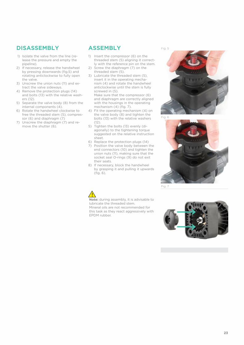
DISASSEMBLY ASSEMBLY 1) Isolate the valve from the line (re-
lease the pressure and empty the pipeline).
2) If necessary, release the handwheel by pressing downwards (fig.5) and rotating anticlockwise to fully open the valve.
3) Unscrew the union nuts (11) and ex-tract the valve sideways.
4) Remove the protection plugs (14) and bolts (13) with the relative wash-ers (12).
5) Separate the valve body (8) from the internal components (4).
6) Rotate the handwheel clockwise to free the threaded stem (5), compres-sor (6) and diaphragm (7)
7) Unscrew the diaphragm (7) and re-move the shutter (6).
1) Insert the compressor (6) on the threaded stem (5) aligning it correct-ly with the reference pin on the stem.
2) Screw the diaphragm (7) on the threaded stem (5).
3) Lubricate the threaded stem (5), insert it in the operating mecha-nism (4) and rotate the handwheel anticlockwise until the stem is fully screwed in (5).
Make sure that the compressor (6) and diaphragm are correctly aligned with the housings in the operating mechanism (4) (fig. 7).
4) Fit the operating mechanism (4) on the valve body (8) and tighten the bolts (13) with the relative washers (12).
5) Tighten the bolts (13) evenly (di-agonally) to the tightening torque suggested on the relative instruction sheet.
6) Replace the protection plugs (14)7) Position the valve body between the
end connectors (10) and tighten the union nuts (11), making sure that the socket seal O-rings (9) do not exit their seats.
8) If necessary, block the handwheel by grasping it and pulling it upwards (fig. 6).
Note: during assembly, it is advisable to lubricate the threaded stem. Mineral oils are not recommended for this task as they react aggressively with EPDM rubber.
Fig. 5
Fig. 6
Fig. 7
23
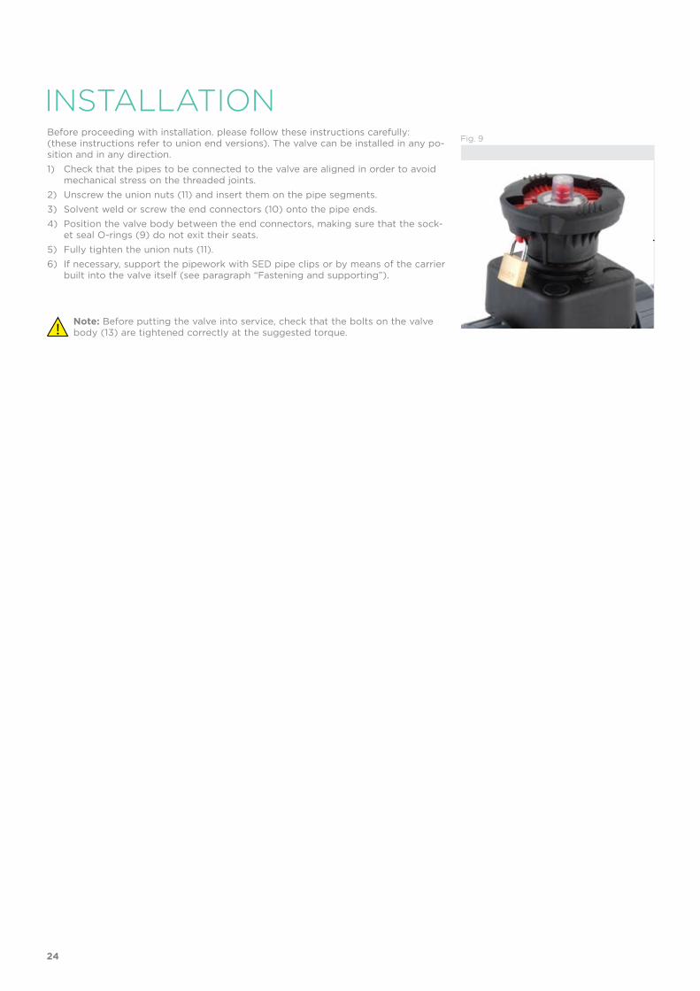
INSTALLATIONBefore proceeding with installation. please follow these instructions carefully: (these instructions refer to union end versions). The valve can be installed in any po-sition and in any direction.
1) Check that the pipes to be connected to the valve are aligned in order to avoid mechanical stress on the threaded joints.
2) Unscrew the union nuts (11) and insert them on the pipe segments.
3) Solvent weld or screw the end connectors (10) onto the pipe ends.
4) Position the valve body between the end connectors, making sure that the sock-et seal O-rings (9) do not exit their seats.
5) Fully tighten the union nuts (11).
6) If necessary, support the pipework with SED pipe clips or by means of the carrier built into the valve itself (see paragraph “Fastening and supporting”).
Note: Before putting the valve into service, check that the bolts on the valve body (13) are tightened correctly at the suggested torque.
Fig. 9
24
DE
F
ADjUSTMENT
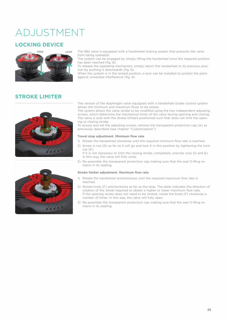
The 882 valve is equipped with a handwheel locking system that prevents the valve from being operated.The system can be engaged by simply lifting the handwheel once the required position has been reached (fig. 8).To release the operating mechanism, simply return the handwheel to its previous posi-tion by pushing it downwards (fig. 6).When the system is in the locked position, a lock can be installed to protect the plant against unwanted interference (fig. 9).
The version of the diaphragm valve equipped with a handwheel stroke control system allows the minimum and maximum flows to be preset.The system allows the valve stroke to be modified using the two independent adjusting screws, which determine the mechanical limits of the valve during opening and closing. The valve is sold with the stroke limiters positioned such that does not limit the open-ing or closing stroke.To access and set the adjusting screws, remove the transparent protection cap (A) as previously described (see chapter “Customization”).
Travel stop adjustment. Minimum flow rate
1) Rotate the handwheel clockwise until the required minimum flow rate is reached.
2) Screw in nut (D) as far as it will go and lock it in this position by tightening the lock-nut (E).
If it is not necessary to limit the closing stroke, completely unscrew nuts (D and E). In this way, the valve will fully close.
3) Re-assemble the transparent protection cap making sure that the seal O-Ring re-mains in its seating.
Stroke limiter adjustment. Maximum flow rate
1) Rotate the handwheel anticlockwise until the required maximum flow rate is reached.
2) Rotate knob (F) anticlockwise as far as the stop. The plate indicates the direction of rotation of the wheel required to obtain a higher or lower maximum flow rate.
If the opening stroke does not need to be limited, rotate the knob (F) clockwise a number of times. In this way, the valve will fully open.
3) Re-assemble the transparent protection cap making sure that the seal O-Ring re-mains in its seating.
LOCKING DEVICE
STROKE LIMITER
FREE LOCK
25
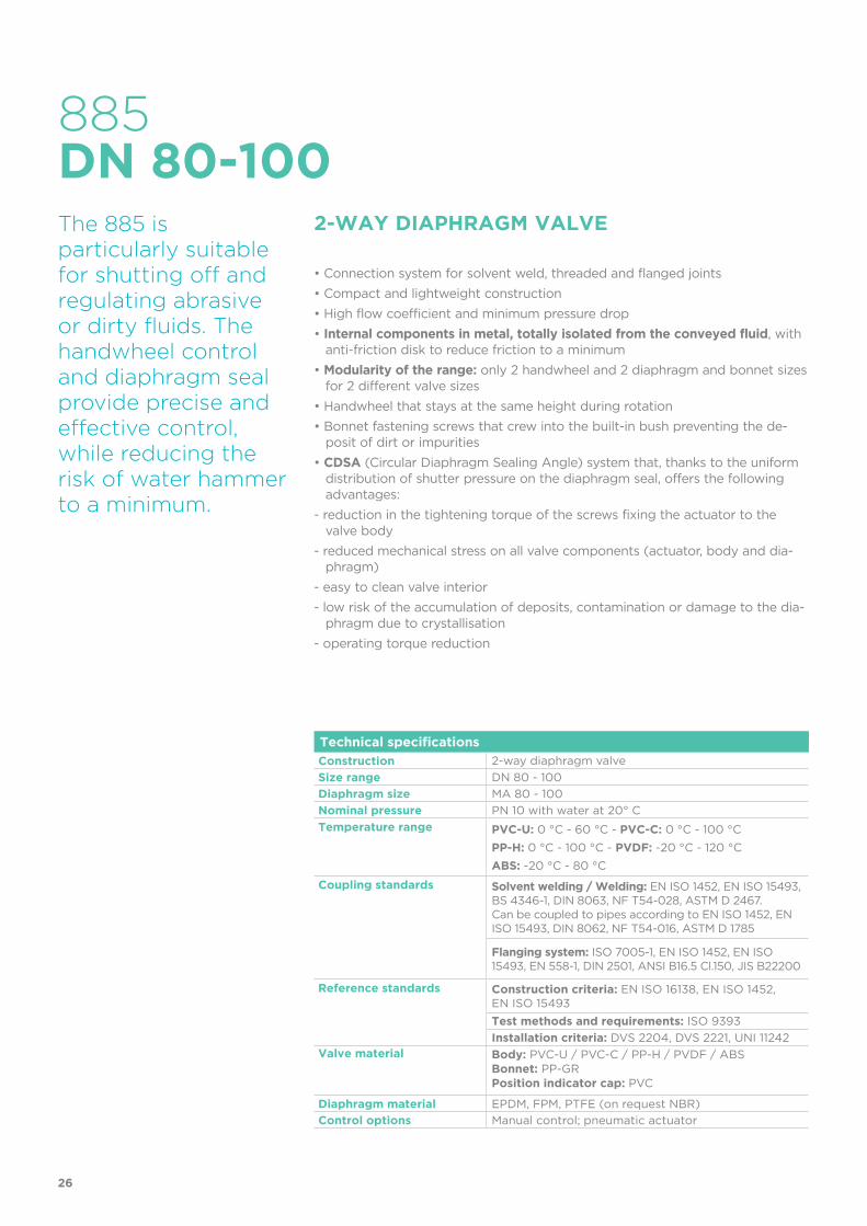
Technical specifications
Construction 2-way diaphragm valve
Size range DN 80 - 100
Diaphragm size MA 80 - 100
Nominal pressure PN 10 with water at 20° C
Temperature range PVC-U: 0 °C - 60 °C - PVC-C: 0 °C - 100 °C
PP-H: 0 °C - 100 °C - PVDF: -20 °C - 120 °C
ABS: -20 °C - 80 °C
Coupling standards Solvent welding / Welding: EN ISO 1452, EN ISO 15493, BS 4346-1, DIN 8063, NF T54-028, ASTM D 2467. Can be coupled to pipes according to EN ISO 1452, EN ISO 15493, DIN 8062, NF T54-016, ASTM D 1785
Flanging system: ISO 7005-1, EN ISO 1452, EN ISO 15493, EN 558-1, DIN 2501, ANSI B16.5 Cl.150, JIS B22200
Reference standards Construction criteria: EN ISO 16138, EN ISO 1452, EN ISO 15493
Test methods and requirements: ISO 9393
Installation criteria: DVS 2204, DVS 2221, UNI 11242Valve material Body: PVC-U / PVC-C / PP-H / PVDF / ABS
Bonnet: PP-GRPosition indicator cap: PVC
Diaphragm material EPDM, FPM, PTFE (on request NBR)
Control options Manual control; pneumatic actuator
885
The 885 is particularly suitable for shutting off and regulating abrasive or dirty fluids. The handwheel control and diaphragm seal provide precise and effective control, while reducing the risk of water hammer to a minimum.
2-WAY DIAPHRAGM VALVE
• Connection system for solvent weld, threaded and flanged joints
• Compact and lightweight construction
• High flow coefficient and minimum pressure drop
• Internal components in metal, totally isolated from the conveyed fluid, with anti-friction disk to reduce friction to a minimum
• Modularity of the range: only 2 handwheel and 2 diaphragm and bonnet sizes for 2 different valve sizes
• Handwheel that stays at the same height during rotation
• Bonnet fastening screws that crew into the built-in bush preventing the de-posit of dirt or impurities
• CDSA (Circular Diaphragm Sealing Angle) system that, thanks to the uniform distribution of shutter pressure on the diaphragm seal, offers the following advantages:
- reduction in the tightening torque of the screws fixing the actuator to the valve body
- reduced mechanical stress on all valve components (actuator, body and dia-phragm)
- easy to clean valve interior
- low risk of the accumulation of deposits, contamination or damage to the dia-phragm due to crystallisation
- operating torque reduction
DN 80-100
26
1
3
5
4
2
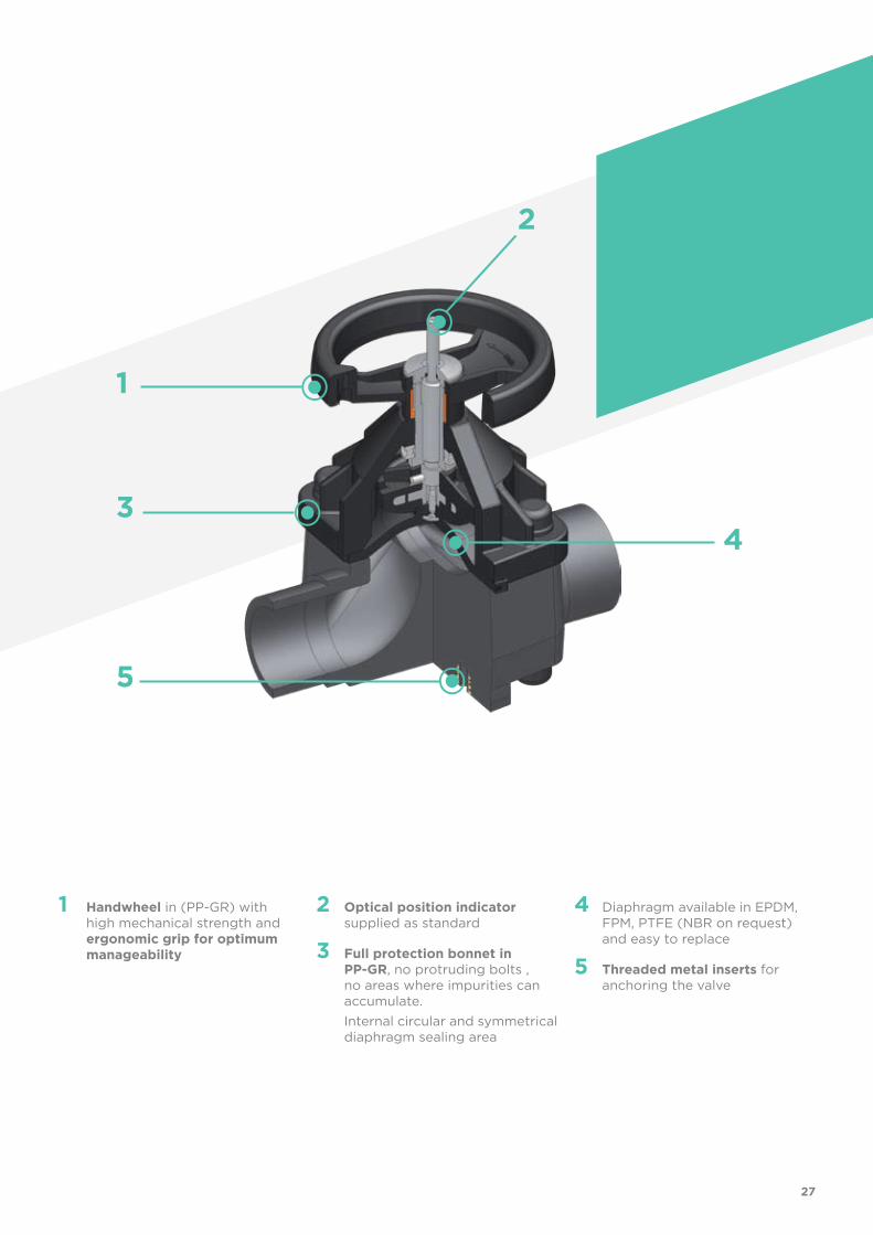
1 Handwheel in (PP-GR) with high mechanical strength and ergonomic grip for optimum manageability
2 Optical position indicator supplied as standard
3 Full protection bonnet in PP-GR, no protruding bolts , no areas where impurities can accumulate.
Internal circular and symmetrical diaphragm sealing area
4 Diaphragm available in EPDM, FPM, PTFE (NBR on request) and easy to replace
5 Threaded metal inserts for anchoring the valve
27
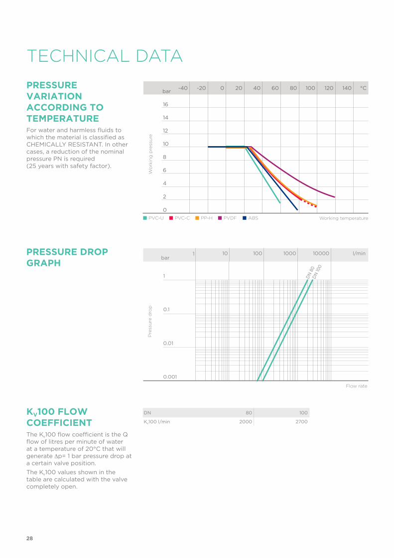
TECHNICAL DATA
PRESSURE VARIATION ACCORDING TO TEMPERATUREFor water and harmless fluids to which the material is classified as CHEMICALLY RESISTANT. In other cases, a reduction of the nominal pressure PN is required (25 years with safety factor).
DN 80 100
Kv100 l/min 2000 2700
KV100 FLoW COEFFICIENTThe Kv100 flow coefficient is the Q flow of litres per minute of water at a temperature of 20°C that will generate ∆p= 1 bar pressure drop at a certain valve position.
The Kv100 values shown in the table are calculated with the valve completely open.
Flow rate
PRESSURE DROP GRAPH
Pre
ssu
re d
rop
bar1 10 100 1000 10000 l/min
1
0.1
0.01
0.001
DN
80
DN
100
-40 -20 0 20 40 60 80 100 120 140 °C
16
14
12
10
8
6
4
2
0
Wo
rkin
g p
ress
ure
Working temperature
bar
PVC-U PVC-C PP-H PVDF ABS
28
Jh
f
d
i
h
h1
l
B1
B
lJh
i
h
h1
B1
B
F
Sp
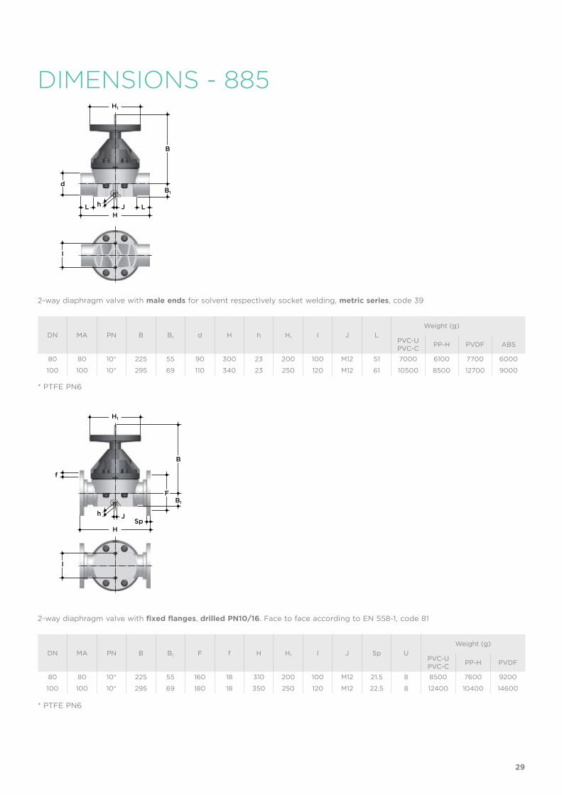
DIMENSIONS - 885
DN MA PN B B1 d H h H1 I J L
Weight (g)
PVC-UPVC-C
PP-H PVDF ABS
80 80 10* 225 55 90 300 23 200 100 M12 51 7000 6100 7700 6000
100 100 10* 295 69 110 340 23 250 120 M12 61 10500 8500 12700 9000
DN MA PN B B1 F f H H1 I J Sp U
Weight (g)
PVC-UPVC-C
PP-H PVDF
80 80 10* 225 55 160 18 310 200 100 M12 21.5 8 8500 7600 9200
100 100 10* 295 69 180 18 350 250 120 M12 22.5 8 12400 10400 14600
2-way diaphragm valve with male ends for solvent respectively socket welding, metric series, code 39
* PTFE PN6
* PTFE PN6
2-way diaphragm valve with fixed flanges, drilled PN10/16. Face to face according to EN 558-1, code 81
29
Jh
f
i
h
h1
B1
B
F
Sp
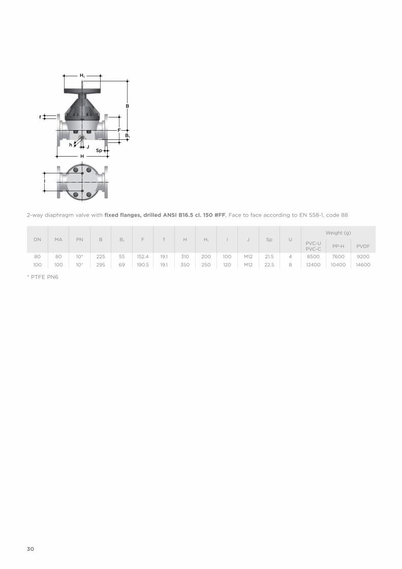
2-way diaphragm valve with fixed flanges, drilled ANSI B16.5 cl. 150 #FF, Face to face according to EN 558-1, code 88
DN MA PN B B1 F f H H1 I J Sp U
Weight (g)
PVC-UPVC-C
PP-H PVDF
80 80 10* 225 55 152.4 19.1 310 200 100 M12 21.5 4 8500 7600 9200
100 100 10* 295 69 190.5 19.1 350 250 120 M12 22.5 8 12400 10400 14600
* PTFE PN6
30
1
2
3
4
6
7
8
9
5
10
12
11
10
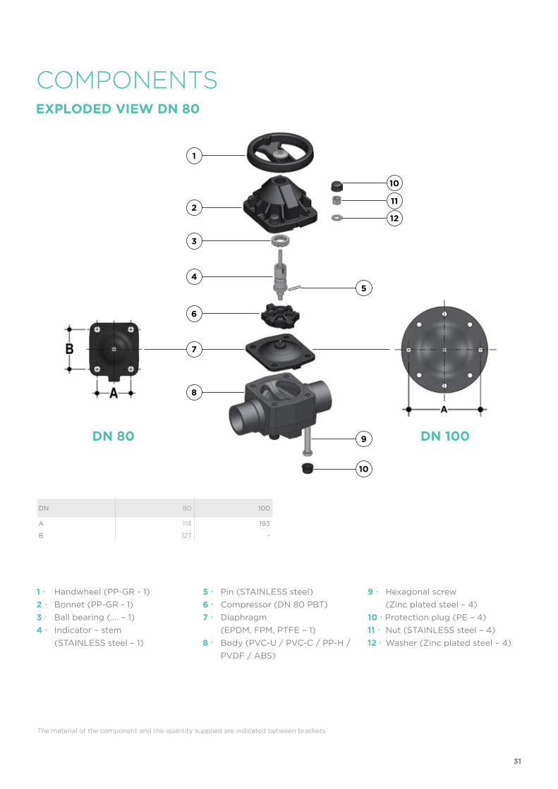
COMPONENTSEXPLoDED VIEW DN 80
DN 80 DN 100
DN 80 100
A 114 193
B 127 -
The material of the component and the quantity supplied are indicated between brackets
1 Handwheel (PP-GR - 1)
2 Bonnet (PP-GR - 1)
3 Ball bearing (…. – 1)
4 Indicator – stem
(STAINLESS steel – 1)
5 Pin (STAINLESS steel)
6 Compressor (DN 80 PBT)
7 Diaphragm
(EPDM, FPM, PTFE – 1)
8 Body (PVC-U / PVC-C / PP-H /
PVDF / ABS)
9 Hexagonal screw
(Zinc plated steel – 4)
10 Protection plug (PE – 4)
11 Nut (STAINLESS steel – 4)
12 Washer (Zinc plated steel – 4)
31
INSTALLATIONThe valve can be installed in any position and in any direction.When starting up the plant, make sure that there are no leaks from between thediaphragm and the valve body. If necessary, tighten the fastening screws (9).
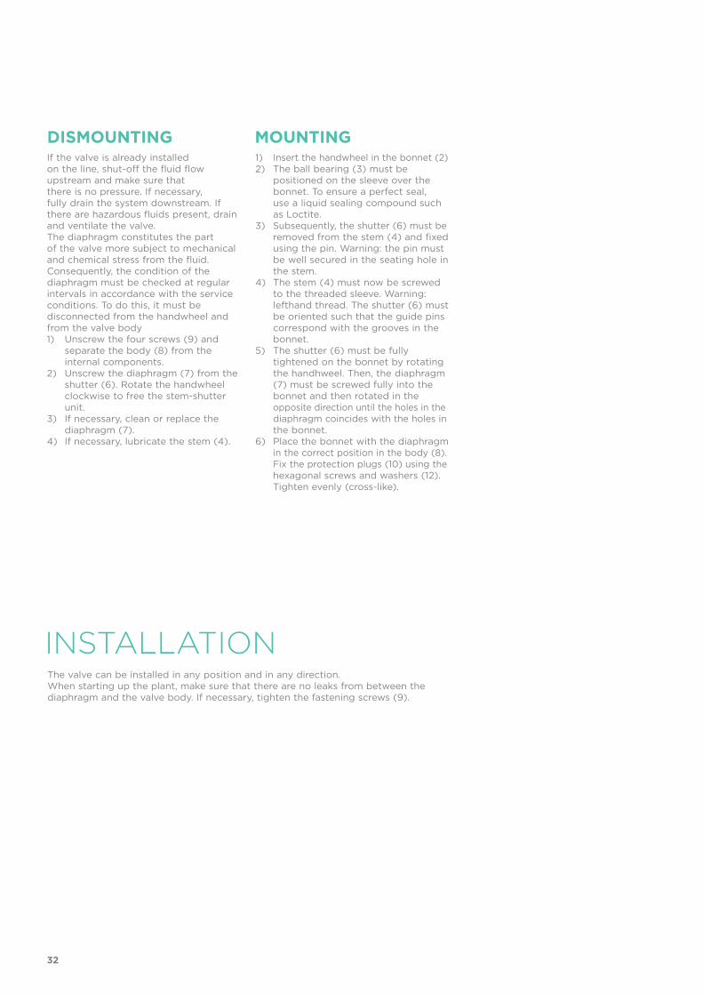
If the valve is already installedon the line, shut-off the fluid flowupstream and make sure thatthere is no pressure. If necessary,fully drain the system downstream. Ifthere are hazardous fluids present, drainand ventilate the valve.The diaphragm constitutes the partof the valve more subject to mechanicaland chemical stress from the fluid.Consequently, the condition of thediaphragm must be checked at regularintervals in accordance with the serviceconditions. To do this, it must bedisconnected from the handwheel andfrom the valve body1) Unscrew the four screws (9) and separate the body (8) from the internal components.2) Unscrew the diaphragm (7) from the shutter (6). Rotate the handwheel clockwise to free the stem-shutter unit.3) If necessary, clean or replace the diaphragm (7).4) If necessary, lubricate the stem (4).
1) Insert the handwheel in the bonnet (2)2) The ball bearing (3) must be positioned on the sleeve over the bonnet. To ensure a perfect seal, use a liquid sealing compound such as Loctite.3) Subsequently, the shutter (6) must be removed from the stem (4) and fixed using the pin. Warning: the pin must be well secured in the seating hole in the stem.4) The stem (4) must now be screwed to the threaded sleeve. Warning: lefthand thread. The shutter (6) must be oriented such that the guide pins correspond with the grooves in the bonnet.5) The shutter (6) must be fully tightened on the bonnet by rotating the handhweel. Then, the diaphragm (7) must be screwed fully into the bonnet and then rotated in the opposite direction until the holes in the diaphragm coincides with the holes in the bonnet.6) Place the bonnet with the diaphragm in the correct position in the body (8). Fix the protection plugs (10) using the hexagonal screws and washers (12). Tighten evenly (cross-like).
DISMOUNTING MOUNTING
32
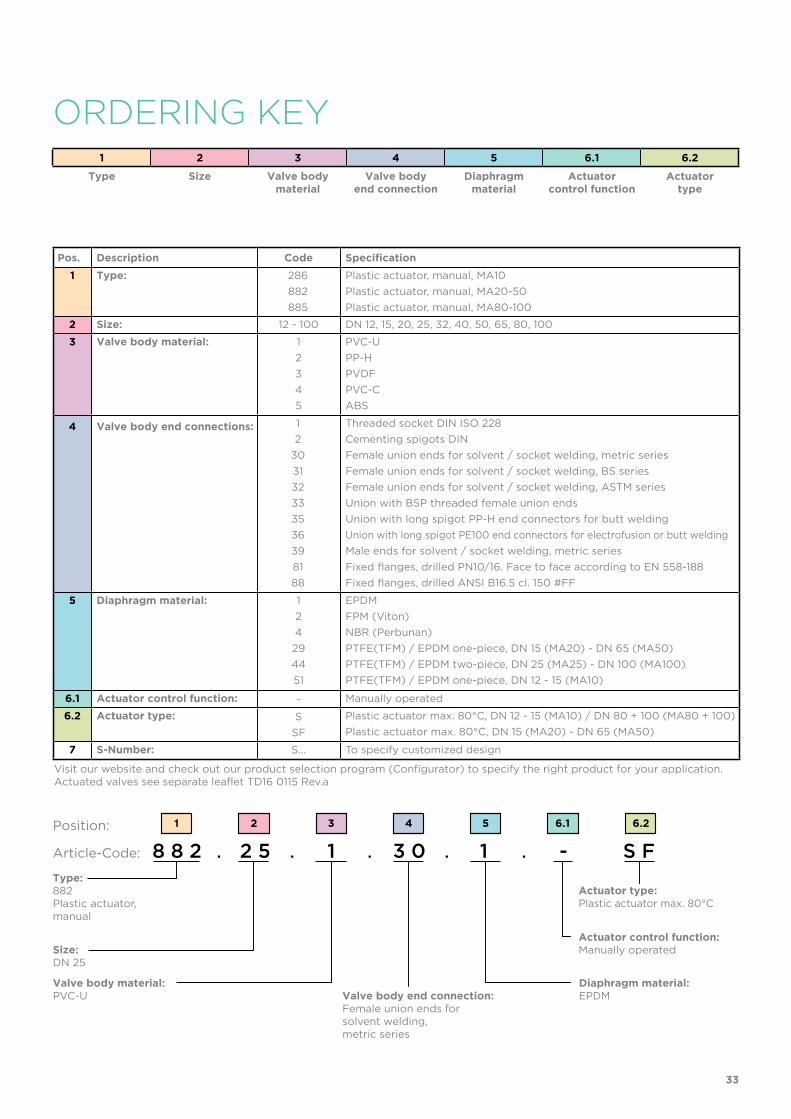
8 8 2 2 5 1 3 0 1 - S F
54321 6.1 6.2
Pos. Description Code Specification
1 Type: 286
882
885
Plastic actuator, manual, MA10
Plastic actuator, manual, MA20-50
Plastic actuator, manual, MA80-100
2 Size: 12 - 100 DN 12, 15, 20, 25, 32, 40, 50, 65, 80, 100
3 Valve body material: 1
2
3
4
5
PVC-U
PP-H
PVDF
PVC-C
ABS
4 Valve body end connections: 1
2
30
31
32
33
35
36
39
81
88
Threaded socket DIN ISO 228
Cementing spigots DIN
Female union ends for solvent / socket welding, metric series
Female union ends for solvent / socket welding, BS series
Female union ends for solvent / socket welding, ASTM series
Union with BSP threaded female union ends
Union with long spigot PP-H end connectors for butt welding
Union with long spigot PE100 end connectors for electrofusion or butt welding
Male ends for solvent / socket welding, metric series
Fixed flanges, drilled PN10/16. Face to face according to EN 558-188
Fixed flanges, drilled ANSI B16.5 cl. 150 #FF
5 Diaphragm material: 1
2
4
29
44
51
EPDM
FPM (Viton)
NBR (Perbunan)
PTFE(TFM) / EPDM one-piece, DN 15 (MA20) - DN 65 (MA50)
PTFE(TFM) / EPDM two-piece, DN 25 (MA25) - DN 100 (MA100)
PTFE(TFM) / EPDM one-piece, DN 12 - 15 (MA10)
6.1 Actuator control function: - Manually operated
6.2 Actuator type: S
SF
Plastic actuator max. 80°C, DN 12 - 15 (MA10) / DN 80 + 100 (MA80 + 100)
Plastic actuator max. 80°C, DN 15 (MA20) - DN 65 (MA50)
7 S-Number: S... To specify customized design
1 2 3 4 5 6.1 6.2
Type Size Valve body material
Valve bodyend connection
Diaphragmmaterial
Actuatorcontrol function
Actuatortype
Visit our website and check out our product selection program (Configurator) to specify the right product for your application.Actuated valves see separate leaflet TD16 0115 Rev.a
ORDERINg kEY
Type:882Plastic actuator,manual
Actuator type:Plastic actuator max. 80°C
Position:
Article-Code:
Size:DN 25
Valve body material:PVC-U
Diaphragm material:EPDMValve body end connection:
Female union ends forsolvent welding,metric series
Actuator control function:Manually operated
33
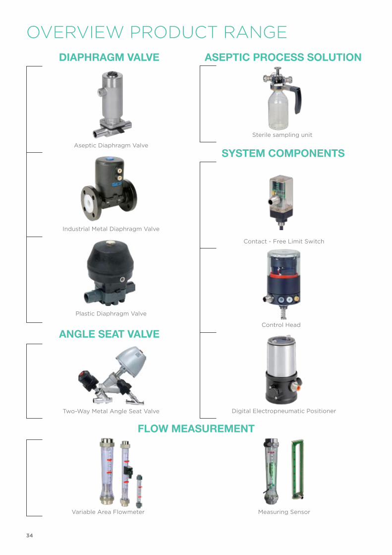
Angle SeAt VAlVe
ASeptic proceSS Solution
Flow MeASureMent
Aseptic Diaphragm Valve
Industrial Metal Diaphragm Valve
Plastic Diaphragm Valve
Two-Way Metal Angle Seat Valve
Measuring Sensor
Contact - Free Limit Switch
Control Head
Digital Electropneumatic Positioner
Variable Area Flowmeter
Sterile sampling unit
DiAphrAgM VAlVe
SySteM coMponentS
OVERVIEW PRODUCT RANgE
34

ManualDiaphragm Valve
SED Flow Control GmbHAm Schafbaum 2 · 74906 Bad RappenauTelefon: +49 7264 921 0 · Telefax: +49 7264 921 21E-Mail: [email protected] · Internet: www.sed-flowcontrol.com
CATALOG
SMART IN FLOW CONTROL.
TD16
011
4 Re
v.a, S
ubje
ct to
alte
ratio
n