premier - clow canada · nearest you. clow canada's premier d-67-m incorporates several new...
TRANSCRIPT
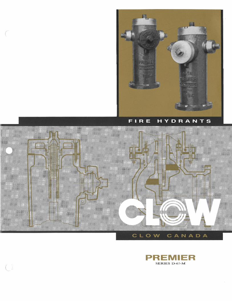
PREMIER SERIES D-67-M
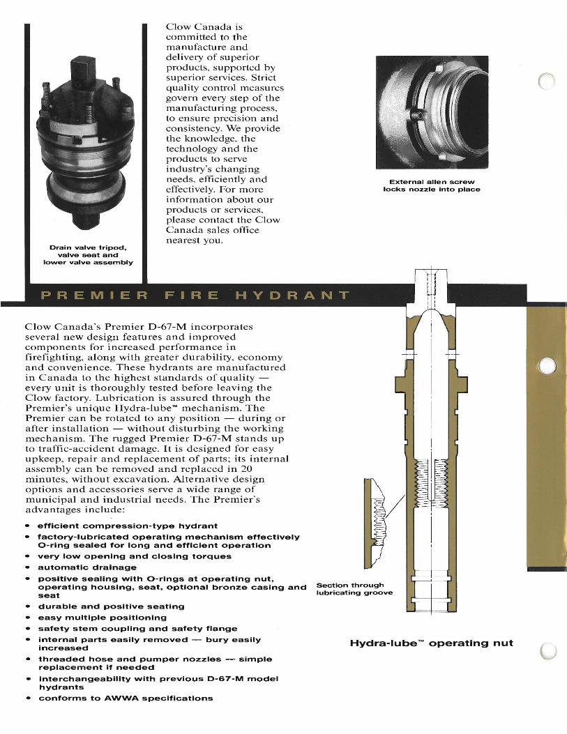
Drain valve tripod, valve seat and
lower valve assembly
Clow Canada is committed to the manufacture and delivery of superior products, supported by superior services. Strict quality control measures govern every step of the manufacturing process, to ensure precision and
. consistency. We provide the knowledge, the technology and the products to serve industry's changing needs, efficiently and effectively. For more information about our products or services, please contact the Clow Canada sales office nearest you.
Clow Canada's Premier D-67-M incorporates several new design features and improved components for increased performance in firefighting, along with greater durability, economy and convenience. These hydrants are manufactured in Canada to the highest standards of quality every unit is thoroughly tested before leaving the Clow factory. Lubrication is assured through the Premier's unique Hydra-lube"" mechanism. The Premier can be rotated to any position - during or after installation - without disturbing the working mechanism. The rugged Premier D-67-M stands up to traffic-accident damage. It is designed for easy upkeep, repair and replacement of parts; its internal assembly can be removed and replaced in 20 minutes, without excavation. Alternative design options and accessories serve a wide range of municipal and industrial needs. The Premier's advantages include:
• efficient compression-type hydrant
• factory-lubricated operating mechanism effectively O-ring sealed for long and efficient operation
• very lovv opening and closing torques
• automatic drainage
• positive sealing vvith O-rings at operating nut, operating housing, seat, optional bronze casing and seat
• durable and positive seating
• easy multiple positioning
• safety stem coupling and safety flange
• internal parts easily removed - bury easily increased
• threaded hose and pumper nozzles - simple replacement if needed
• interchangeability vvith previous D-67-M model hydrants
• conforms to AWWA specifications
External allen screw locks nozzle into place
Section through lubricating groove
Hydra-lube'" operating nut
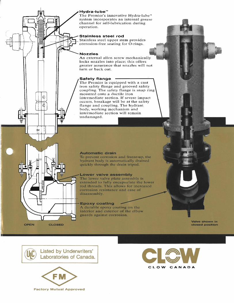
Hydra-lube™ The Premier's innovative Hydra-Iube T
"
system incorporates an internal grease channel for self-lubrication during operation.
Stainless steel rod -+-+--+- Stainless steel upper stem provides
corrosion-free seating for O-rings.
Nozzles An external allen screw mechanically locks nozzles into place; this offers greater assurance that nozzles will not turn or back out.
Safety flange The Premier is equipped with a cast iron safety flange and grooved safety coupling. The safety flange is snap ring mounted onto a ductile iron intermediate section. If severe impact occurs, breakage will be at the safety flange and coupling. The hydrant body, working mechanism and intermediate section will remain undamaged.
A ....tomatlc drain To prevent corrosion and freeze-up. the hydrant body is automatically drained quickly through the drain tripod.
Lower valve assembly The lower valve plate assembly is extended to fully encapsulate the lower rod threads. This allows for increased corrosion resistance and ease of disassembly.
~----,f-+--++-tfo-Epoxy coating A durable epoxy coating on the interior and exterior of the elbow guards against corrosion.
OPEN CLOSED
Listed by Underwriters' Laboratories of Canada. CLew
CLOW CANADA
Factory Mutual Approved
43
Optional brass to brass seat
4g55!lt~~46)~45 /---23
/ooloItF+J+"'---47
24
~---tt------12
17
18
13
14
16
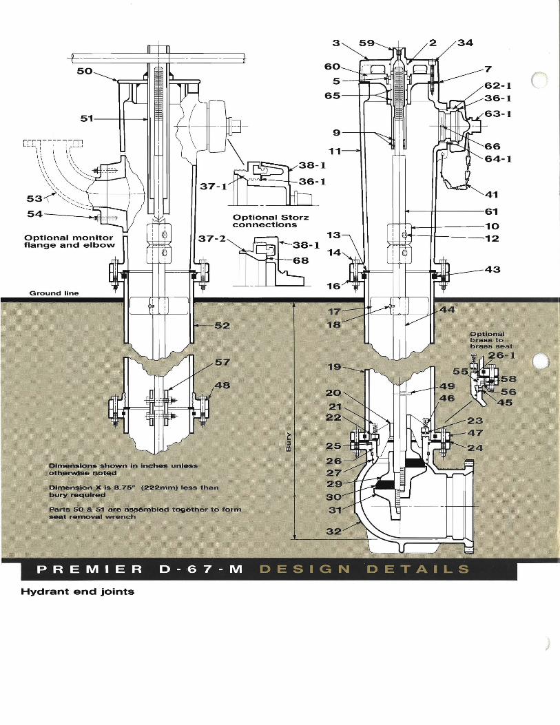
Optional Storz connections
57
52
48
37-1
37-2
50
51---++---..l1
Parts 50 & 51 ate assembled together to form seat removal wrench
Dimensions shown In Inches unl_ othe'l'VI(l8!Et I)oted
DimensIOn X ,Is 8.7,5" (222mm) less than bury required
Ground line
66 64-1
343
60
5---ti;l;;;~---rT-"
65 --+-t-<: I
~41 1-----H-----61
l-----+1f-----10
Hydrant end joints
4"
Flanged 8,50"
Mechanical
.Join-tlte
DIMENSION
6"
8,50"
8,50"
8,75"
A
Flanged Mechanical .Join-tlte
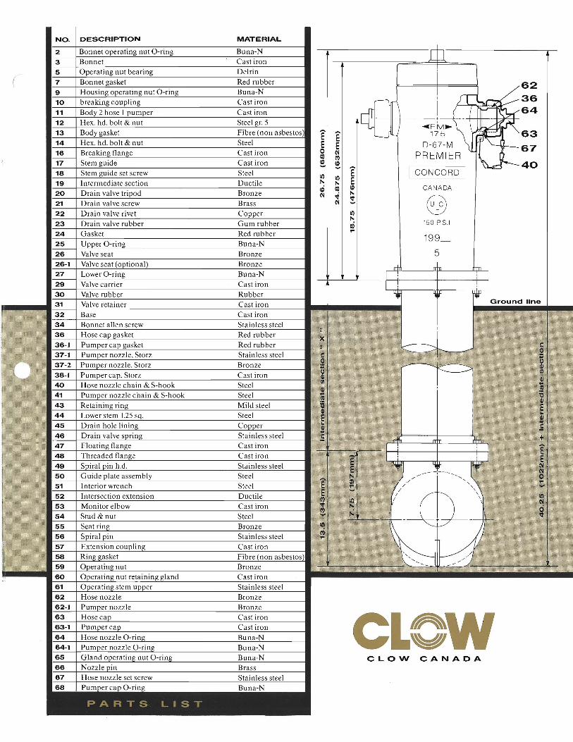
NO. DESCRIPTION MATERIAL I
2 Bonnet operating nut O-ring Buna-N ill3 Bonnet Cast iron !5 Operating nut bearing Delrin
7 Bonnet gasket Red rubber( I 62 9 Housing operating nut O-ring Buna-N 10 breaking coupling Cast iron i !I,... 36 11 Body 2 hose I pumper Cast iron ~-- -+----t~-+- ~6412 Hex. hd. bolt & nut Steel gr. 5 ..... FM~ /11 13 Body gasket Fibre (non asbestos) 175 t-'rI c- 63E 14 Hex. hd. bolt & nut Steel E D-67-M Itl "-.Jr- 67 o16 Breaking flange Cast iron PREMIER -I..I~CO 17 Stem guide Cast iron ~ ~ 40 18 Stem guide set screw Steel I CONCORD I
19 Intermediate section Ductile CANADA
20 Drain valve tripod Bronze 21 Drain valve screw Brass @
.. II)
'" 22 Drain valve rivet Copper
150 P.S.1.23 Drain valve rubber Gum rubber ai24 Gasket Red rubber 25 Upper O-ring Buna-N 26 Valve seat Bronze 26-1 Valve seat (optional) Bronze n+ I-+n 27 Lower O-ring Bu na-N I ' I 29 Valve carrier Cast iron -+------'---'----- I ! ! I 30 Valve rubber Rubber '------r~Ttn----n+rr----n"llf+n---J
1IIII••••• _~3~1_+V~ailll~v~eE're::It<1alIinl<:e:t:r ~C~as~t~i~ro~n~ 1 Ground line
32 Base Cast iron 34 Bonnet allen screw Stainless steel 36 Hose cap gasket Red rubber x 36-1 Pumper cap gasket Red rubber 37-1 Pumper nozzle. Storz Stainless steel 37-2 Pumper nozzle. Storz Bronze 38-1 Pumper cap. Storz Cast iron 40 Hose nozzle chain & S-hook Steel 41 Pumper nozzle chain & S-hook Steel 43 Retaining ring Mild steel 44 Lower stem 1.25 sq. Steel 45 Drain hole lining Copper 46 Drain valve spring Stainless steel 47 Floating flange Cast iron 48 Threaded flange Cast iron 49 Spiral pin h.d. Stainless steel 50 Guide plate assembly Steel 51 Interior wrench Steel 52 Intersection extension Ductile 53 Monitor elbow Cast iron 54 Stud & nut Steel 55 Seat ring Bronze 56 Spiral pin Stainless steel 57 Extension coupling Cast iron 58 Ring gasket Fibre (non asbestos) 59 Operating nut Bronze
II)
l'i..
- T-
60 Operating nut retaining gland Cast iron 61 Operating stem upper Stainless steel 62 Hose nozzle Bronze 62-1 Pumper nozzle Bronze 63
63-1
64
64-1
Hose cap Pumper cap Hose nozzle O-rino
Pumper nozzle O-ring
Cast iron Cast iron Buna-N Buna-N CLOW
65 Gland operating nut O-ring Buna-N CLOW CANADA 66 Nozzle pin Brass 67 Hose nozzle set screw Stainless steel 68 P o• B N
PARTS LIST
L WCLOW CANADA
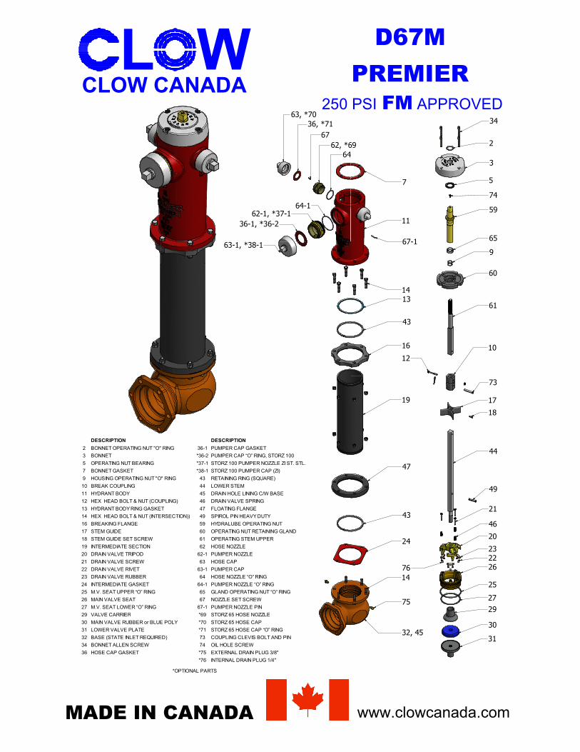
DESCRIPTION DESCRIPTION
2 BONNET OPERATING NUT "O" RING 36-1 PUMPER CAP GASKET
3 BONNET *36-2 PUMPER CAP “O” RING, STORZ 100
5 OPERATING NUT BEARING *37-1 STORZ 100 PUMPER NOZZLE ZI ST. STL.
7 BONNET GASKET *38-1 STORZ 100 PUMPER CAP (ZI)
9 HOUSING OPERATING NUT "O" RING 43 RETAINING RING (SQUARE)
10 BREAK COUPLING 44 LOWER STEM
11 HYDRANT BODY 45 DRAIN HOLE LINING C/W BASE
12 HEX HEAD BOLT & NUT (COUPLING) 46 DRAIN VALVE SPRING
13 HYDRANT BODY RING GASKET 47 FLOATING FLANGE
14 HEX HEAD BOLT & NUT (INTERSECTION)) 49 SPIROL PIN HEAVY DUTY
16 BREAKING FLANGE 59 HYDRALUBE OPERATING NUT
17 STEM GUIDE 60 OPERATING NUT RETAINING GLAND
18 STEM GUIDE SET SCREW 61 OPERATING STEM UPPER
19 INTERMEDIATE SECTION 62 HOSE NOZZLE
20 DRAIN VALVE TRIPOD 62-1 PUMPER NOZZLE
21 DRAIN VALVE SCREW 63 HOSE CAP
22 DRAIN VALVE RIVET 63-1 PUMPER CAP
23 DRAIN VALVE RUBBER 64 HOSE NOZZLE “O” RING
24 INTERMEDIATE GASKET 64-1 PUMPER NOZZLE “O” RING
25 M.V. SEAT UPPER “O” RING 65 GLAND OPERATING NUT “O” RING
26 MAIN VALVE SEAT 67 NOZZLE SET SCREW
27 M.V. SEAT LOWER “O” RING 67-1 PUMPER NOZZLE PIN
29 VALVE CARRIER *69 STORZ 65 HOSE NOZZLE
30 MAIN VALVE RUBBER or BLUE POLY *70 STORZ 65 HOSE CAP
31 LOWER VALVE PLATE *71 STORZ 65 HOSE CAP “O” RING
32 BASE (STATE INLET REQUIRED) 73 COUPLING CLEVIS BOLT AND PIN
34 BONNET ALLEN SCREW 74 OIL HOLE SCREW
36 HOSE CAP GASKET *75 EXTERNAL DRAIN PLUG 3/8"
*76 INTERNAL DRAIN PLUG 1/4"
*OPTIONAL PARTS
MADE IN CANADA www.clowcanada.com
D67MPREMIER
250 PSI FM APPROVED34
2
3
5
74
59
65
9
60
61
10
73
12
17
18
44
49
21
46
20
2322
76 26
25
2729
30
3132, 45
75
14
24
43
47
19
16
43
1314
67-1
11
7
6462, *69
6736, *71
63, *70
64-162-1, *37-1
36-1, *36-2
63-1, *38-1
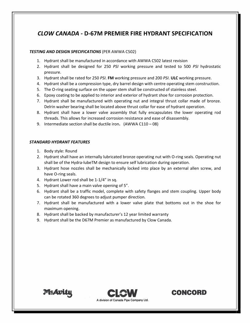
CLOW CANADA - D-67M PREMIER FIRE HYDRANT SPECIFICATION
TESTING AND DESIGN SPECIFICATIONS (PER AWWA C502)
1. Hydrant shall be manufactured in accordance with AWWA C502 latest revision
2. Hydrant shall be designed for 250 PSI working pressure and tested to 500 PSI hydrostatic
pressure.
3. Hydrant shall be rated for 250 PSI. FM working pressure and 200 PSI. ULC working pressure.
4. Hydrant shall be a compression type, dry barrel design with centre operating stem construction.
5. The O-ring seating surface on the upper stem shall be constructed of stainless steel.
6. Epoxy coating to be applied to interior and exterior of hydrant shoe for corrosion protection.
7. Hydrant shall be manufactured with operating nut and integral thrust collar made of bronze.
Delrin washer bearing shall be located above thrust collar for ease of hydrant operation.
8. Hydrant shall have a lower valve assembly that fully encapsulates the lower operating rod
threads. This allows for increased corrosion resistance and ease of disassembly.
9. Intermediate section shall be ductile iron. (AWWA C110 – 08)
STANDARD HYDRANT FEATURES
1. Body style: Round
2. Hydrant shall have an internally lubricated bronze operating nut with O-ring seals. Operating nut
shall be of the Hydra-lubeTM design to ensure self lubrication during operation.
3. Hydrant hose nozzles shall be mechanically locked into place by an external allen screw, and
have O-ring seals.
4. Hydrant Lower rod shall be 1-1/4” in sq.
5. Hydrant shall have a main valve opening of 5”.
6. Hydrant shall be a traffic model, complete with safety flanges and stem coupling. Upper body
can be rotated 360 degrees to adjust pumper direction.
7. Hydrant shall be manufactured with a lower valve plate that bottoms out in the shoe for
maximum opening.
8. Hydrant shall be backed by manufacturer’s 12 year limited warranty
9. Hydrant shall be the D67M Premier as manufactured by Clow Canada.
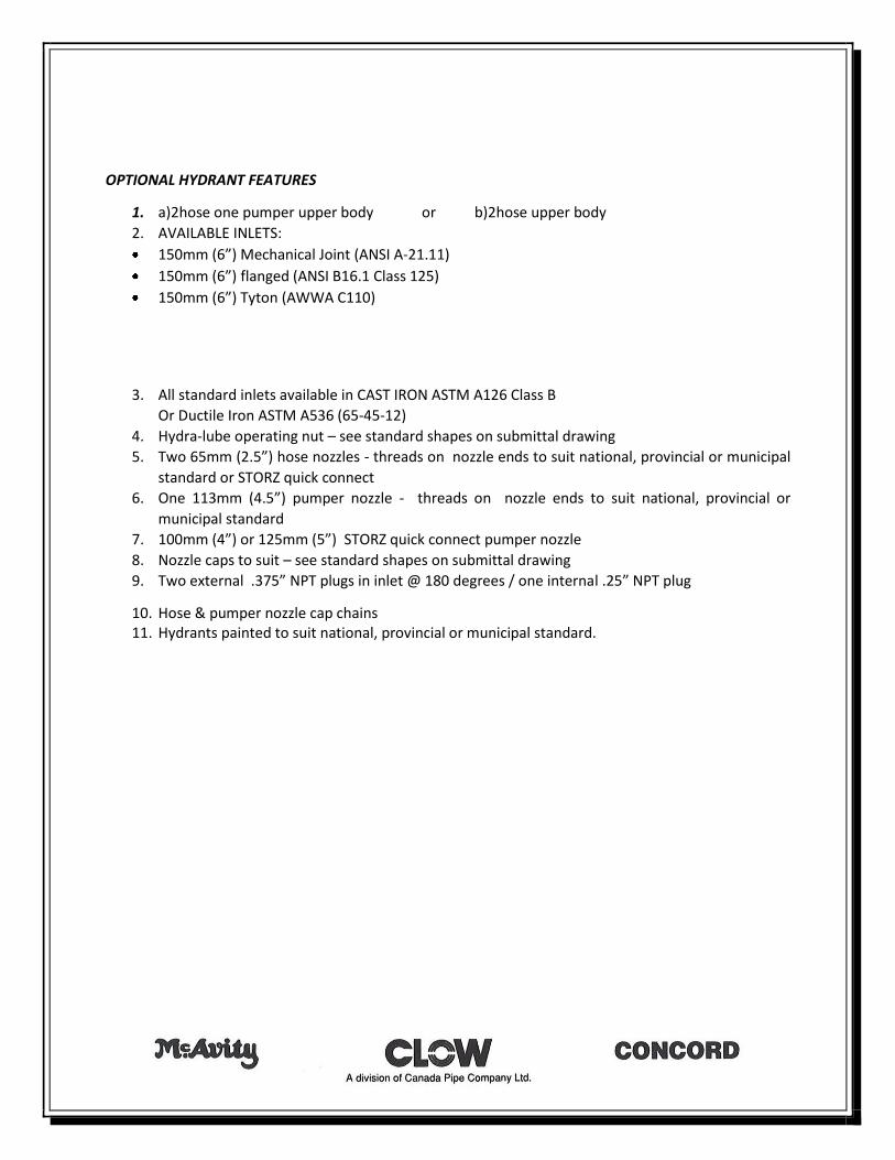
OPTIONAL HYDRANT FEATURES
1. a)2hose one pumper upper body or b)2hose upper body
2. AVAILABLE INLETS:
150mm (6”) Mechanical Joint (ANSI A-21.11)
150mm (6”) flanged (ANSI B16.1 Class 125)
150mm (6”) Tyton (AWWA C110)
3. All standard inlets available in CAST IRON ASTM A126 Class B
Or Ductile Iron ASTM A536 (65-45-12)
4. Hydra-lube operating nut – see standard shapes on submittal drawing
5. Two 65mm (2.5”) hose nozzles - threads on nozzle ends to suit national, provincial or municipal
standard or STORZ quick connect
6. One 113mm (4.5”) pumper nozzle - threads on nozzle ends to suit national, provincial or
municipal standard
7. 100mm (4”) or 125mm (5”) STORZ quick connect pumper nozzle
8. Nozzle caps to suit – see standard shapes on submittal drawing
9. Two external .375” NPT plugs in inlet @ 180 degrees / one internal .25” NPT plug
10. Hose & pumper nozzle cap chains 11. Hydrants painted to suit national, provincial or municipal standard.
(
0-67 0-67-M
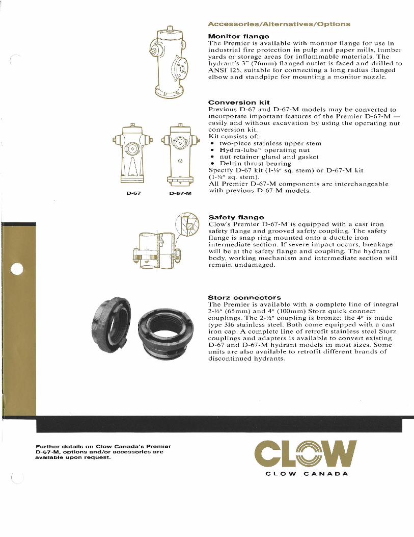
Accessories/Alternatives/Options
Monitor flange The Premier is available with monitor flange for use in industrial fire protection in pulp and paper mills. lumber yards or storage areas for inflammable matel'ials, The hydrant's 3" (76mm) flanged outlet is faced and drilled to ANSI 125. suitable for connecting a long radius flanged elbow and standpipe for mounting a monitor nozzle,
ConversIon kit Pl'evious 0-67 and 0-67-M models may be converted to incorporate important features of the Premier 0-67-M easily and without excavation by using the operating nut conversion kit. Kit consists of: • two-piece stainless upper stem • Hydl'a-Iube'" operating nut • nut retainer gland and gasket • Oelrin thrust bearing Specify 0-67 kit (I-IN' sq, stem) or 0-67-M kit (l-W' sq. stem). All Pl'emier 0-67-M components are interchangeable with pl'evious 0-67-M models,
Safety flange Clow's Premier 0-67-M is equipped with a cast iron safety flange and grooved safety coupling. The safety flange is snap ring mounted onto a ductile il'on intermediate section. If severe impact occurs, breakage will be at the safety flange and coupling. The hydrant body, working mechanism and intel'mediate section will remain undamaged,
Storz connectors The Premier is available with a complete line of integral 2-Yz" (65mm) and 4" (lOOmm) Storz quick connect couplings. The 2-Yz" coupling is bronze; the 4" is made type 316 stainless steel. Both come equipped with a cast iron cap. A complete line of retrofit stainless steel Storz couplings and adapters is available to convert existing 0-67 and 0-67-M hydrant models in most sizes, Some units are also available to retrofit different bl'ands of discontinued hydrants.
Further details on Clow Canada's Premier 0-67-M, options and/or accessories are available upon request. CLew
CLOW CANADA(
(
EASTERN CANADA Grandview Industrial Park
P.D. Box 700 Saint John NB E2L 4B3
Tel. (506) 633-2541 Fax (506) 634-8936
WESTERN CANADA 801 Smelter Ave. S.E.
P.O. Box 1000 Medicine Hat AB TIA 7Hl
Tel. (403) 527-3553 Fax (403) 527-7454
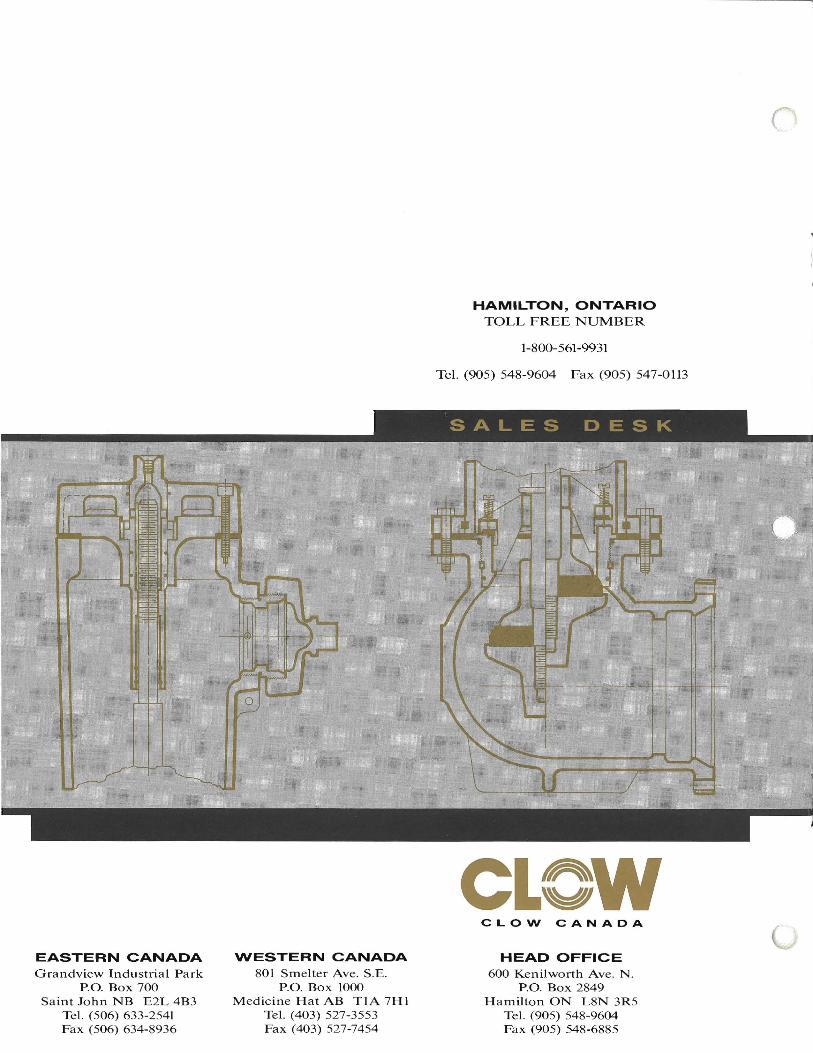
HAMILTON, ONTARIO TOLL FREE NUMBER
1-800-561-9931
Tel. (905) 548-9604 Fax (905) 547-0113
SALES DESK
CLew CLOW CANADA
HEAD OFFICE 600 Kenilworth Ave. N.
P.D. Box 2849 Hamilton ON L8N 3R5
Tel. (905) 548-9604 Fax (905) 548-6885