ms2830a signal analyzer vector signal generator operation
TRANSCRIPT

MS2830A Signal Analyzer Vector Signal Generator
Operation Manual Remote Control
For safety and warning information, please read this manual before attempting to use the equipment.
Additional safety and warning information is provided within the MS2830A Signal Analyzer Operation Manual (Mainframe Operation) and the MS2830A Signal
Analyzer Vector Signal Generator Option Operation Manual (Operation). Please also refer to these documents before using the equipment.
Keep this manual with the equipment.
Third Edition
ANRITSU CORPORATION
Document No.: M-W3338AE-3.0

Safety Symbols
To prevent the risk of personal injury or loss related to equipment malfunction, Anritsu Corporation uses the
following safety symbols to indicate safety-related information. Ensure that you clearly understand the meanings of
the symbols BEFORE using the equipment. Some or all of the following symbols may be used on all Anritsu
equipment. In addition, there may be other labels attached to products that are not shown in the diagrams in this
manual.
Symbols used in manual
DANGER This indicates a very dangerous procedure that could result in serious injury or death if not performed properly.
WARNING This indicates a hazardous procedure that could result in serious injury or death if not performed properly.
CAUTION This indicates a hazardous procedure or danger that could result in light-to-severe injury, or loss related to equipment malfunction, if proper precautions are not taken.
Safety Symbols Used on Equipment and in Manual The following safety symbols are used inside or on the equipment near operation locations to provide information
about safety items and operation precautions. Ensure that you clearly understand the meanings of the symbols and
take the necessary precautions BEFORE using the equipment.
This indicates a prohibited operation. The prohibited operation is indicated symbolically in or near the barred circle.
ii
This indicates an obligatory safety precaution. The obligatory operation is
indicated symbolically in or near the circle. This indicates a warning or caution. The contents are indicated symbolically in or
near the triangle. This indicates a note. The contents are described in the box. These indicate that the marked part should be recycled.
MS2830A Signal Analyzer Vector Signal Generator Operation Manual Remote Control 15 December 2009 (First Edition) 15 October 2010 (Third Edition) Copyright © 2009-2010, ANRITSU CORPORATION. All rights reserved. No part of this manual may be reproduced without the prior written permission of the publisher. The contents of this manual may be changed without prior notice. Printed in Japan

Notes On Export Management
This product and its manuals may require an Export License/Approval by
the Government of the product's country of origin for re-export from your
country.
Before re-exporting the product or manuals, please contact us to confirm
whether they are export-controlled items or not.
When you dispose of export-controlled items, the products/manuals need
to be broken/shredded so as not to be unlawfully used for military purpose.
iii

iv

About This Manual Composition of Operation Manuals
The operation manuals for the MS2830A Signal Analyzer are comprised as shown in the figure below.
MS2830A Signal Analyzer Vector Signal Generator Operation Manual (Operation)
MS2830A Signal Analyzer Operation Manual (Mainframe Operation)
MS2690A/MS2691A/MS2692A and MS2830A Signal Analyzer
Operation Manual (Mainframe Remote Control)
MS2690A/MS2691A/MS2692A and MS2830A Signal Analyzer Vector Signal Generator Operation Manual (Standard Waveform Pattern)
Communication System Supporting IQproducerTM Operation Manual
MS2690A/MS2691A/MS2692A and MS2830A Signal Analyzer Vector Signal Generator Operation Manual (IQproducer™)
MS2830A Signal Analyzer Vector Signal Generator Operation Manual (Remote Control)
I

II
Signal Analyzer Operation Manual (Mainframe Operation)
Signal Analyzer Operation Manual (Mainframe Remote Control)
These manuals describe basic operating methods, maintenance procedures, common functions, and common remote control of the signal analyzer mainframe.
Vector Signal Generator Operation Manual (Operation)
This manual describes functions, operating methods, and so on of the vector signal generator (option).
Vector Signal Generator Operation Manual (Remote Control) (This
manual)
This manual describes remote control of the vector signal generator (option).
Vector Signal Generator Operation Manual (IQproducerTM)
This manual describes functions, operating methods, and so on of the IQproducer, which is application software used with the vector signal generator (option).
Vector Signal Generator Operation Manual (Standard Waveform
Pattern)
This manual describes details on the standard waveform pattern data used with the vector signal generator (option).

1
3
4
III
2
Table of Contents
About This Manual........................................ I
Chapter 1 Overview.................................... 1-1 1.1 Overview ....................................................................... 1-2
Chapter 2 SCPI Device Message............... 2-1 2.1 Setting Frequency......................................................... 2-3
2.2 Setting Level ................................................................. 2-9
2.3 Controlling Waveform Patterns in Waveform Memory.. 2-26
2.4 Controlling Waveform Patterns in HDD ........................ 2-36
2.5 Modulation and AWGN Settings ................................... 2-44
2.6 External In/Output Settings........................................... 2-52
2.7 External output signal settings...................................... 2-64
2.8 Setting Trigger to Be Output to SG Marker
of SA/SPA ..................................................................... 2-77
2.9 Display Settings ............................................................ 2-79
2.10 Other Settings ............................................................... 2-81
Chapter 3 Native Device Message List..... 3-1
3.1 IEEE488.2 Common Device Messages........................ 3-2 3.2 Application Common Device Messages ....................... 3-4 3.3 Frequency Settings ....................................................... 3-7 3.4 Level Settings ............................................................... 3-8 3.5 Controlling Waveform Patterns in Waveform
Memory ......................................................................... 3-10 3.6 Controlling Waveform Patterns in HDD ........................ 3-12 3.7 Modulation and AWGN Settings ................................... 3-13 3.8 External Input Signal Settings....................................... 3-14 3.9 External Output Signal Settings.................................... 3-16 3.10 Setting Trigger to Be Output to SG Marker of
SA/SPA ......................................................................... 3-17 3.11 Display Settings ............................................................ 3-18
Chapter 4 Native Device Message Details 4-1

IV.

Chapter 1 Overview
1-1
1
Overview
This chapter provides an overview of the remote control of the Spectrum Analyzer function (hereinafter, referred to as “this application”).
1.1 Overview.................................................................... 1-2

Chapter 1 Overview
1-2.
1.1 Overview Automatic measurement can be performed by using this instrument in connection with an external controller (PC). This instrument is standardly equipped with GPIB, Ethernet, and USB interfaces. You can also select a remote control command from the SCPI mode, which is a command format defined by the SCPI Consortium, and Native mode, which is our unique format. See the “MS2690A/MS2691A/MS2692A and MS2830A Signal Analyzer Operation Manual (Mainframe Remote Control)” for how to switch the language mode.
You can use the Native mode by converting SCPI commands into Native ones. See the “MS2690A/MS2691A/MS2692A and MS2830A Signal Analyzer Operation Manual (Mainframe Remote Control)” for details.

Chapter 2 SCPI Device Message
2-1
2
SC
PI D
evice Message
This chapter describes the detailed specifications of SCPI remote control commands for executing the functions of this application. The device messages are listed according to function. Refer to the “MS2690A/MS2691A/MS2692A and MS2830A Signal Analyzer Operation Manual (Mainframe Remote Control)” for detailed specifications off the IEEE488.2 common device messages and application common device messages.
2.1 Setting Frequency...................................................... 2-3 2.1.1 Frequency...................................................... 2-4 2.1.2 Frequency Step Value................................... 2-6 2.1.3 RF Spectrum ................................................. 2-8
2.2 Setting Level .............................................................. 2-9 2.2.1 Output Level Unit........................................... 2-10 2.2.2 Volt Unit Display ............................................ 2-11 2.2.3 RF Output ...................................................... 2-12 2.2.4 Unit Power ..................................................... 2-13 2.2.5 SG Level Calibration...................................... 2-14 2.2.6 Relative Level Value...................................... 2-15 2.2.7 Relative Level ................................................ 2-17 2.2.8 Reference of Relative Level .......................... 2-18 2.2.9 Level Status List ............................................ 2-19 2.2.10 Level Offset Value ......................................... 2-20 2.2.11 Level Offset ................................................... 2-21 2.2.12 Output Level Step Value ............................... 2-22 2.2.13 Output Level .................................................. 2-23
2.3 Controlling Waveform Patterns in Waveform
Memory ...................................................................... 2-26 2.3.1 Delete Pattern file on Wave Memory............. 2-27 2.3.2 Delete All Pattern files on Wave Memory...... 2-28 2.3.3 List of Loaded Pattern Files........................... 2-29 2.3.4 Number of loaded pattern files ...................... 2-30 2.3.5 Wave Memory Size ....................................... 2-31 2.3.6 Select Pattern file on Wave Memory ............. 2-32 2.3.7 Waveform Restart.......................................... 2-34 2.3.8 ARB Status Query ......................................... 2-35
2.4 Controlling Waveform Patterns in HDD ..................... 2-36 2.4.1 Copy pattern file to Hard Disk Drive.............. 2-37 2.4.2 Delete Pattern file on Hard Disk Drive........... 2-38 2.4.3 Load Pattern File / Query Load Status and
Wave Memory ............................................... 2-39 2.4.4 Cancel Loading.............................................. 2-41 2.4.5 Pattern File Version....................................... 2-42 2.4.6 Hard Disk Drive Size ..................................... 2-43

Chapter 2 SCPI Device Message
2-2
2.5 Modulation and AWGN Settings ................................ 2-44 2.5.1 Modulation ..................................................... 2-45 2.5.2 AWGN ........................................................... 2-46 2.5.3 C/N Ratio ....................................................... 2-47 2.5.4 Target of C/N Setting..................................... 2-49 2.5.5 Carrier Power ................................................ 2-50 2.5.5 Sampling Clock.............................................. 2-51
2.6 External In/Output Settings........................................ 2-52 2.6.1 Pulse Modulation Source .............................. 2-53 2.6.2 External Trigger Mode................................... 2-54 2.6.3 External Trigger ............................................. 2-55 2.6.4 External Trigger Source ................................ 2-56 2.6.5 External Trigger Delay................................... 2-57 2.6.6 External Trigger Delay Time.......................... 2-59 2.6.7 External Trigger Edge.................................... 2-60 2.6.8 Baseband Reference Clock Source .............. 2-61 2.6.9 Baseband Reference Clock........................... 2-62 2.6.10 Frame Count.................................................. 2-64 2.6.11 Remote Command Trigger............................ 2-65
2.7 External output signal settings................................... 2-66 2.7.1 Marker Polarity .............................................. 2-67 2.7.2 Marker Edit .................................................... 2-69 2.7.3 Marker Pulse Cycle Value ............................. 2-71 2.7.4 Marker Pulse Start Offset Value.................... 2-73 2.7.5 Marker Pulse Width Value............................. 2-75
2.8 Setting Trigger to Be Output to SG Marker of
SA/SPA...................................................................... 2-77 2.8.1 SA Trigger Out............................................... 2-77
2.9 Display Settings ......................................................... 2-79 2.9.1 SG Window Position...................................... 2-79
2.10 Other Settings............................................................ 2-81 2.10.1 SG Status ...................................................... 2-81

2.1 Setting Frequency
2-3
2
SC
PI D
evice Message
2.1 Setting Frequency Table 2.1-1 shows device messages for frequency.
Table 2.1-1 Device messages for frequency
Function Device Messages
[:SOURce]:FREQuency[:CW|:FIXed] <freq> Frequency
[:SOURce]:FREQuency[:CW|:FIXed]?
[:SOURce]:FREQuency:STEP[:INCRement] <numeric_value> Frequency Step Value
[:SOURce]:FREQuency:STEP[:INCRement]?
[:SOURce]:DM:POLarity[:ALL] NORMal|INVert RF Spectrum
[:SOURce]:DM:POLarity[:ALL]?

Chapter 2 SCPI Device Message
2-4
2.1.1 Frequency
[:SOURce]:FREQuency[:CW|:FIXed] <freq> Frequency
Function
Sets frequency
Command
[:SOURce]:FREQuency[:CW|:FIXed] <freq>
Parameter
<freq> Frequency
Range 250 kHz to 3.6 GHz (*) 250 kHz to 6 GHz (**)
Resolution 0.01 Hz Default 1 GHz Suffix code HZ, KHZ, KZ, MHZ, MZ, GHZ, GZ When omitted: Hz
(*) When option 020/120 is installed. (**) When option 021/121 is installed.
Example of Use
To set the frequency to 800 MHz FREQ 800MHZ

2.1 Setting Frequency
2-5
2
SC
PI D
evice Message
[:SOURce]:FREQuency[:CW|:FIXed]? Frequency Query
Function
This command queries the frequency.
Query
[:SOURce]:FREQuency[:CW|:FIXed]?
Response
<freq>
Parameter
<freq> Frequency
Range 250 kHz to 3.6 GHz (*) 250 kHz to 6 GHz (**)
Resolution 0.01 Hz Default 1 GHz
(*) When option 020/120 is installed. (**) When option 021/121 is installed.
Example of Use
To query the frequency. FREQ?
> 800000000.00

Chapter 2 SCPI Device Message
2-6
2.1.2 Frequency Step Value
[:SOURce]:FREQuency:STEP[:INCRement] <numeric_value> Frequency - Step Value
Function
This command sets the amount the frequency to be incremented or decremented (frequency step width) when the frequency setting is stepped up or down.
Command
[:SOURce]:FREQuency:STEP[:INCRement] <numeric_value>
Parameter
<numeric_value> Frequency step width
Range 0.01 Hz to 1 GHz Resolution 0.01 Hz Default 100 kHz Suffix code HZ, KHZ, KZ, MHZ, MZ, GHZ, GZ When omitted: Hz
Example of Use
To set the frequency step width to 200 kHz. FREQ:STEP 200KHZ
2.1 Setting Frequency
2-7
2
SC
PI D
evice Message
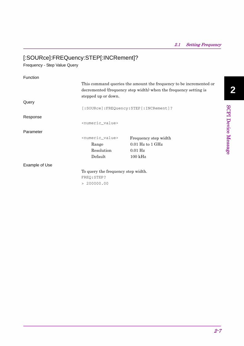
[:SOURce]:FREQuency:STEP[:INCRement]? Frequency - Step Value Query
Function
This command queries the amount the frequency to be incremented or decremented (frequency step width) when the frequency setting is stepped up or down.
Query
[:SOURce]:FREQuency:STEP[:INCRement]?
Response
<numeric_value>
Parameter
<numeric_value> Frequency step width
Range 0.01 Hz to 1 GHz Resolution 0.01 Hz Default 100 kHz
Example of Use
To query the frequency step width. FREQ:STEP?
> 200000.00

Chapter 2 SCPI Device Message
2-8
2.1.3 RF Spectrum
[:SOURce]:DM:POLarity[:ALL] NORMal|INVert RF Spectrum - Reverse/Normal
Function
This command whether to invert spectrum of the output waveform (reverses I and Q).
Command
[:SOURce]:DM:POLarity[:ALL] <mode>
Parameter
<mode> Whether to invert output waveform
NORMal Normal:Do not invert INVert Reverse:Invert
Example of Use
To invert the output waveform. DM:POL INV
[:SOURce]:DM:POLarity[:ALL]? RF Spectrum - Reverse/Normal Query
Function
This command queries the status of the spectrum invert (reverses I and Q) of the output waveform.
Query
[:SOURce]:DM:POLarity[:ALL]?
Response
<mode>
Parameter
<mode> Whether to invert output waveform NORM Normal:Do not invert INV Reverse:Invert
Example of Use
To query the invert status of the output waveform. DM:POL?
> INV

2.2 Setting Level
2-9
2
SC
PI D
evice Message
2.2 Setting Level Table 2.2-1 shows device messages for setting level.
Table 2.2-1 Device messages for level
Function Device Messages
:DISPlay:ANNotation:AMPLitude:UNIT DBM|DBU Output Level Unit
:DISPlay:ANNotation:AMPLitude:UNIT?
:DISPlay:ANNotation:AMPLitude:UNIT:VOLTage EMF|TERM Volt Unit Display
:DISPlay:ANNotation:AMPLitude:UNIT:VOLTage?
:OUTPut[:STATe] ON|OFF|1|0 RF Output
:OUTPut[:STATe]?
:UNIT:POWer DBM|DBUV|DBUVEMF Unit Power
:UNIT:POWer?
SG Level Calibration [:SOURce]:POWer:ALC:SEARch {ONCE}
[:SOURce]:POWer:REFerence:AMPLitude <numeric_value> Relative Level Value
[:SOURce]:POWer:REFerence:AMPLitude?
[:SOURce]:POWer:REFerence:STATe ON|OFF|1|0 Relative Level
[:SOURce]:POWer:REFerence:STATe?
Reference of Relative Level
[:SOURce]:POWer:REFerence?
Level Status List [:SOURce]:POWer:SETTing?
[:SOURce]:POWer[:LEVel][:IMMediate]:OFFSet <numeric_value> Level Offset Value
[:SOURce]:POWer[:LEVel][:IMMediate]:OFFSet?
[:SOURce]:POWer[:LEVel][:IMMediate]:OFFSet:STATe ON|OFF|1|0 Level Offset
[:SOURce]:POWer[:LEVel][:IMMediate]:OFFSet:STATe?
[:SOURce]:POWer[:LEVel][:IMMediate]:STEP[:INCRement] <numeric_value> Output Level Step Value [:SOURce]:POWer[:LEVel][:IMMediate]:STEP[:INCRement]?
[:SOURce]:POWer[:LEVel][:IMMediate][:AMPLitude] <numeric_value> Output Level [:SOURce]:POWer[:LEVel][:IMMediate][:AMPLitude]? {<unit>}

Chapter 2 SCPI Device Message
2-10
2.2.1 Output Level Unit
:DISPlay:ANNotation:AMPLitude:UNIT DBM|DBU Level Unit
Function
This command sets the output level unit.
Command
:DISPlay:ANNotation:AMPLitude:UNIT <unit>
Parameter
<unit> Output level unit DBM dBm DBU dBV
Example of Use
To set the level setting unit to dBm. DISP:ANN:AMPL:UNIT DBM
:DISPlay:ANNotation:AMPLitude:UNIT? Level Unit Query
Function
This command queries the output level unit.
Query
:DISPlay:ANNotation:AMPLitude:UNIT?
Response
<unit>
Parameter
<unit> Output level unit DBM dBm DBU dBV
Example of Use
To query the level setting unit. DISP:ANN:AMPL:UNIT?
> DBM

2.2 Setting Level
2-11
2
SC
PI D
evice Message
2.2.2 Volt Unit Display
:DISPlay:ANNotation:AMPLitude:UNIT:VOLTage EMF|TERM Volt Unit
Function
This command sets the display method when the output level is set in voltage units.
Command
:DISPlay:ANNotation:AMPLitude:UNIT:VOLTage <unit>
Parameter
<unit> Voltage unit display system EMF Open circuit voltage display TERM Termination voltage display
Example of Use
To display the voltage units using open voltage. DISP:ANN:AMPL:UNIT:VOLT EMF
:DISPlay:ANNotation:AMPLitude:UNIT:VOLTage? Volt Unit Query
Function
This command queries the display method when the output level is set in voltage units.
Query
:DISPlay:ANNotation:AMPLitude:UNIT:VOLTage?
Response
<unit>
Parameter
<unit> Voltage unit display system EMF Open circuit voltage display TERM Termination voltage display
Example of Use
To query the voltage unit display system
DISP:ANN:AMPL:UNIT:VOLT?
> EMF

Chapter 2 SCPI Device Message
2-12
2.2.3 RF Output
:OUTPut[:STATe] ON|OFF|1|0 RF Output - On/Off
Function
This command turns RF output ON/OFF.
Command
:OUTPut[:STATe] <on_off>
Parameter
<on_off> RF output On/Off ON|1 On OFF|0 Off
Example of Use
To set the RF signal output to Off. OUTP OFF
:OUTPut[:STATe]? RF Output - On/Off Query
Function
This command queries the ON/OFF status of RF output.
Query
:OUTPut[:STATe]?
Response
<on_off>
Parameter
<on_off> RF output On/Off ON|1 On OFF|0 Off
Example of Use
To query the ON/OFF status of RF output. OUTP?
> 1

2.2 Setting Level
2-13
2
SC
PI D
evice Message
2.2.4 Unit Power
:UNIT:POWer DBM|DBUV|DBUVEMF Unit Power
Function
This command sets the output level unit.
Command
:UNIT:POWer <unit>
Parameter
<unit> Output level unit DBM dBm DBUV dBV (terminal voltage display) DBUVEMF dBV (open voltage display)
Example of Use
To set the level setting unit to dBV (open voltage display). UNIT:POW DBUVEMF
:UNIT:POWer? Unit Power Query
Function
This command queries the output level unit.
Query
:UNIT:POWer?
Response
<unit>
Parameter
<unit> Output level unit DBM dBm DBUV dBV (terminal voltage display) DBUVEMF dBV (open voltage display)
Example of Use
To query the level setting unit. UNIT:POW?
> DBM

Chapter 2 SCPI Device Message
2-14
2.2.5 SG Level Calibration
[:SOURce]:POWer:ALC:SEARch {ONCE} SG Level Calibration
Function
This command calibrates the output level.
Command
[:SOURce]:POWer:ALC:SEARch {ONCE}
Example of Use
To calibrate the output level. POW:ALC:SEAR

2.2 Setting Level
2-15
2
SC
PI D
evice Message
2.2.6 Relative Level Value
[:SOURce]:POWer:REFerence:AMPLitude <numeric_value> Relative Level
Function
This command sets the screen display output level at relative output level display mode.
Command
[:SOURce]:POWer:REFerence:AMPLitude <numeric_value>
Parameter
<numeric_value> Relative output level
Range 60 dB width within the range of –60.00 dB to +60.00 dB (> 25 MHz)(*)
42 dB width within the range of –42.00 dB to +42.00 dB (≤ 25 MHz)(*)
151 dB width within the range of –151.00 dB to +151.00 dB (> 25 MHz)(**)
133 dB width within the range of –133.00 dB to +133.00 dB (≤ 25 MHz)(**)
Resolution 0.01 dB Response unit dB (*) When option 022/122 is NOT installed. (**) When option 022/122 is installed.
Details
The range differs as follows according to the conditions:
When Offset is on: Range + Offset Value
Example of Use
To set the relative output to +10.00 dB. POW:REF:AMPL 10.00DB

Chapter 2 SCPI Device Message
2-16
[:SOURce]:POWer:REFerence:AMPLitude? Relative Level Query
Function
This command queries the screen display output level at relative output level display mode.
Query
[:SOURce]:POWer:REFerence:AMPLitude?
Response
<numeric_value>
Parameter
<numeric_value> Relative output level
Range 60 dB width within the range of –60.00 dB to +60.00 dB (> 25 MHz)(*)
42 dB width within the range of –42.00 dB to +42.00 dB (≤ 25 MHz)(*)
151 dB width within the range of –151.00 dB to +151.00 dB (> 25 MHz)(**)
133 dB width within the range of –133.00 dB to +133.00 dB (≤ 25 MHz)(**)
Resolution 0.01 dB Response unit dB (*) When option 022/122 is NOT installed. (**) When option 022/122 is installed.
Details
The range differs as follows according to the conditions:
When Offset is on: Range + Offset Value
Example of Use
To query the relative output level. POW:REF:AMPL?
> 10.00

2.2 Setting Level
2-17
2
SC
PI D
evice Message
2.2.7 Relative Level
[:SOURce]:POWer:REFerence:STATe ON|OFF|1|0 Relative - On/Off
Function
This command sets the relative output level display ON/OFF.
Command
[:SOURce]:POWer:REFerence:STATe <on_off>
Parameter
<on_off> Relative output level display ON|1 On OFF|0 Off
Example of Use
To enable relative output level display. POW:REF:STAT ON
[:SOURce]:POWer:REFerence:STATe? Relative - On/Off Query
Function
This command queries the relative output level display ON/OFF status.
Query
[:SOURce]:POWer:REFerence:STATe?
Response
<on_off>
Parameter
<on_off> Relative output level display 1 On 0 Off
Example of Use
To query the relative output level display ON/OFF status. POW:REF:STAT?
> 1

Chapter 2 SCPI Device Message
2-18
2.2.8 Reference of Relative Level
[:SOURce]:POWer:REFerence? Relative Level - Reference Level Query
Function
This command queries the relative output level in the relative output level display mode (the output level when relative output mode is on).
Query
[:SOURce]:POWer:REFerence?
Response
<numeric_value>
Parameter
<numeric_value> Reference level of relative output
Range –40.00 dBm to +20.00 dBm (>25 MHz)(*) –40.00 dBm to +2.00 dBm (≤25 MHz)(*) –136.00 dBm to +15.00 dBm (>25 MHz)(**) –136.00 dBm to –3.00 dBm (≤25 MHz)(**) Resolution 0.01 dB Response unit dBm (*) When option 022/122 is NOT installed. (**) When option 022/122 is installed.
Details
The range is based on an output level unit of dBm.
The range differs as follows according to the conditions:
When dBV (Term) is set as the output level unit
Range + 106.99 dB
When dBV (EMF) is set as the output level unit
Range + 113.01 dB
When Offset is on: Range + Offset Value
Example of Use
To query reference level of relative output POW:REF?
> -5.00

2.2 Setting Level
2-19
2
SC
PI D
evice Message
2.2.9 Level Status List
[:SOURce]:POWer:SETTing? Level Status List Query
Function
This command queries the output level status.
Query
[:SOURce]:POWer:SETTing?
Response
<unit>,<offset>,<unleveled>,INT,0,
<relative>,NORM
Parameter
<unit> Voltage unit display EMF Open circuit voltage TERM Termination voltage
<offset> Level offset 1 On 0 Off
<unleveled> Output level accuracy status NORM Normal state UNL Outside level accuracy assurance
INT Fixed value
Fixed value<relative> Relative output mode 1 On 0 Off
Fixed valueExample of Use
To query the output level status. POW:SETT?
> EMF,0,NORM,1,0

Chapter 2 SCPI Device Message
2-20
2.2.10 Level Offset Value
[:SOURce]:POWer[:LEVel][:IMMediate]:OFFSet <numeric_value> Level Offset - Level
Function
This command sets the output level offset value
Command
[:SOURce]:POWer[:LEVel][:IMMediate]:OFFSet
<numeric_value>
Parameter
<numeric_value> Output level offset
Range 100.00 to +100.00 dB Resolution 0.01 dB Default 0.00 dB
Example of Use
To set the output level offset to –15.00 dB. POW:OFFS –15.00
[:SOURce]:POWer[:LEVel][:IMMediate]:OFFSet? Level Offset - Level Query
Function
This queries the output level offset. Query
[:SOURce]:POWer[:LEVel][:IMMediate]:OFFSet?
Response
<numeric_value>
Parameter
<numeric_value> Output level offset
Range –100.00 to +100.00 dB Resolution 0.01 dB
Example of Use
To query the output level offset. POW:OFFS?
> –5.00

2.2 Setting Level
2-21
2
SC
PI D
evice Message
2.2.11 Level Offset
[:SOURce]:POWer[:LEVel][:IMMediate]:OFFSet:STATe ON|OFF|1|0 Level Offset - On/Off
Function
This command sets the output level offset ON/OFF.
Command
[:SOURce]:POWer[:LEVel][:IMMediate]:OFFSet:STATe <on_off>
Parameter
<on_off> Output level offset On/Off ON|1 On OFF|0 Off
Example of Use
To enable the output level offset. POW:OFFS:STAT ON
[:SOURce]:POWer[:LEVel][:IMMediate]:OFFSet:STATe? Level Offset - On/Off Query
Function
This command queries the output level offset ON/OFF status.
Query
[:SOURce]:POWer[:LEVel][:IMMediate]:OFFSet:STATe?
Response
<on_off>
Parameter
<on_off> Output level offset On/Off 1 On 0 Off
Example of Use
To query the output level offset ON/OFF status. POW:OFFS:STAT?
> 1

Chapter 2 SCPI Device Message
2-22
2.2.12 Output Level Step Value
[:SOURce]:POWer[:LEVel][:IMMediate]:STEP[:INCRement] <numeric_value> Output Level - Set Value
Function
This command sets the numerical value fluctuation width (step value) when the output level is increased/decreased in step units.
Command
[:SOURce]:POWer[:LEVel][:IMMediate]:STEP[:INCRement]
<numeric_value>
Parameter
<numeric_value> Output level step width
Range 0.01 to 100.00 dB Resolution 0.01 dB
Example of Use
To set the output level step width to 5.00 dB. POW:STEP 5.00
[:SOURce]:POWer[:LEVel][:IMMediate]:STEP[:INCRement]? Output Level - Set Value Query
Function
This command queries the numerical value fluctuation width (step value) when the output level is increased/decreased in step units.
Query
[:SOURce]:POWer[:LEVel][:IMMediate]:STEP[:INCRement]?
Response
<numeric_value>
Parameter
<numeric_value> Output level step width
Range 0.01 to 100.00 dB Resolution 0.01 dB
Example of Use
To query the step width of the output level. POW:STEP?
> 0.10

2.2 Setting Level
2-23
2
SC
PI D
evice Message
2.2.13 Output Level
[:SOURce]:POWer[:LEVel][:IMMediate][:AMPLitude] <numeric_value> Output Level
Function
This command sets the output level.
Command
[:SOURce]:POWer[:LEVel][:IMMediate][:AMPLitude]
<numeric_value>
Parameter
<numeric_value> Output Level
Range –40.00 dBm to +20.00 dBm (>25 MHz)(*) –40.00 dBm to +2.00 dBm (≤25 MHz)(*) –136.00 dBm to +15.00 dBm (>25 MHz) (**) –136.00 dBm to –3.00 dBm (≤25 MHz) (**) Resolution 0.01 dB Default –40.00 dBm (*) –136.00 dBm (**) Suffix code DBM,DBU When omitted: DBM
(*) When option 022/122 is NOT installed. (**) Details of when option 022/122 is installed.
The range is based on an output level unit of dBm.
The set range differs as follows according to the setting conditions:
When dBV (Term) is set as the output level unit
Range + 106.99 dB
When dBV (EMF) is set as the output level unit
Range + 113.01 dB
When Offset is on: Range + Offset Value
Example of Use
To set the output level to –30.00 dBm POW –30.00

Chapter 2 SCPI Device Message
2-24
[:SOURce]:POWer[:LEVel][:IMMediate][:AMPLitude]? {<unit>} Output Level Query
Function
This command queries the output level.
Query
[:SOURce]:POWer[:LEVel][:IMMediate][:AMPLitude]? {<unit>}
Response
<numeric_value>
Parameter
<numeric_value> Output Level
Range –40.00 dBm to +20.00 dBm (>25 MHz)(*) –40.00 dBm to +2.00 dBm (≤25 MHz)(*) –136.00 dBm to +15.00 dBm (>25 MHz) (**) –136.00 dBm to –3.00 dBm (≤25 MHz) (**) Resolution 0.01 dB Response unit dBm or dBV (according to the set value)
(*) When option 022/122 is NOT installed. (**) When option 022/122 is installed.
<unit> Output level unit DBM dBm DBU dBV When omitted: dBm
Details
The range is based on an output level unit of dBm.
The range differs as follows according to the conditions:
When dBV (Term) is specified as the output level unit
Range + 106.99 dB
When dBV (EMF) is specified as the output level unit
Range + 113.01 dB
When Offset is on: Range + Offset Value

2.2 Setting Level
2-25
2
SC
PI D
evice Message
Example of Use
To query the output level in dBm. POW? DBM
> -30.00

Chapter 2 SCPI Device Message
2-26
2.3 Controlling Waveform Patterns in Waveform
Memory Table 2.3-1 shows the device messages for controlling waveform patterns loaded into the waveform memory.
Table 2.3-1 Device messages for controlling waveform patterns loaded into the waveform memory
Function Device Message
Delete Pattern file on Wave Memory
:MEMory:DELete[:NAME] <package>,<pattern>
Delete All Pattern files on Wave Memory (Clear Wave Memory)
:MEMory:DELete:ALL
List of Loaded Pattern Files :MEMory:WAVeform:NAME? <numeric_value>
Number of loaded pattern files
:MEMory:WAVeform:COUNt?
Wave Memory Size :MEMory:FREE[:ALL]? [:SOURce]:RADio:ARB:WAVeform <package>,<pattern> Select Pattern file on
Wave Memory [:SOURce]:RADio:ARB:WAVeform?
Waveform Restart [:SOURce]:RADio:ARB:WAVeform:RESTart
ARB Status Query [:SOURce]:RADio:ARB:REGister[:STATus]?

2.3 Controlling Waveform Patterns in Waveform Memory
2-27
2
SC
PI D
evice Message
2.3.1 Delete Pattern file on Wave Memory
:MEMory:DELete[:NAME] <package>,<pattern> Delete Pattern file on Waveform Memory
Function
This command deletes the waveform pattern file in the waveform memory.
Command
:MEMory:DELete[:NAME] <package>,<pattern>
Parameter
<package> Package name (Character string)
<pattern> Pattern name (Character string) Details
This command does not delete waveform patterns on the hard disk.
Example of Use
To delete the "TEST" pattern in the package "WCDMA". MEM:DEL "WCDMA","TEST"

Chapter 2 SCPI Device Message
2-28
2.3.2 Delete All Pattern files on Wave Memory
:MEMory:DELete:ALL Delete Pattern file on Waveform Memory
Function
This command deletes all waveform pattern files in the waveform memory.
Command
:MEMory:DELete:ALL
Details
This command does not delete waveform patterns on the hard disk.
Example of Use
To delete all waveform pattern files in the waveform memory. MEM:DEL:ALL

2.3 Controlling Waveform Patterns in Waveform Memory
2-29
2
SC
PI D
evice Message
2.3.3 List of Loaded Pattern Files
:MEMory:WAVeform:NAME? <numeric_value> Loaded File Name in Waveform Memory Query
Function
This command queries the waveform pattern filename loaded in the waveform memory.
Query
:MEMory:WAVeform:NAME? <numeric_value>
Response
<package>,<pattern>
Parameter
<numeric_value> Random numbers allocated to waveform patterns.
Range 0 to (Number of waveform patterns in the waveform memory - 1)
Resolution 1
<package> Package name (Character string)
<pattern> Pattern name (Character string)
Example of Use
To query the waveform pattern filename loaded in the waveform memory. MEM:WAV:NAME? 2
> "WCDMA","TEST"
Chapter 2 SCPI Device Message
2-30
2.3.4 Number of loaded pattern files
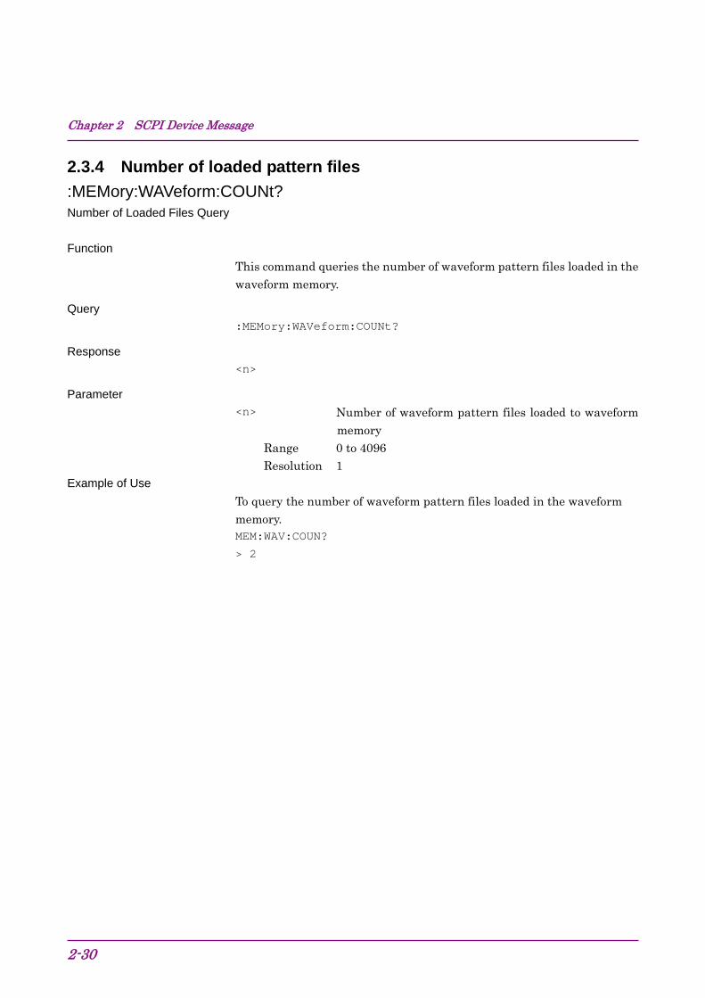
:MEMory:WAVeform:COUNt? Number of Loaded Files Query
Function
This command queries the number of waveform pattern files loaded in the waveform memory.
Query
:MEMory:WAVeform:COUNt?
Response
<n>
Parameter
<n> Number of waveform pattern files loaded to waveform memory
Range 0 to 4096 Resolution 1
Example of Use
To query the number of waveform pattern files loaded in the waveform memory. MEM:WAV:COUN?
> 2

2.3 Controlling Waveform Patterns in Waveform Memory
2-31
2
SC
PI D
evice Message
2.3.5 Wave Memory Size
:MEMory:FREE[:ALL]? Waveform Memory Space Query
Function
This command queries the waveform memory free space.
Query
:MEMory:FREE[:ALL]?
Response
<blank>,<consecutive_blank>,<total>
Parameter
<blank> Free space (in byte)
<consecutive_blank> Contiguous free space (in byte)
<total> Total waveform memory size (in byte)
Example of Use
To query the waveform memory free space. MEM:FREE?

Chapter 2 SCPI Device Message
2-32
2.3.6 Select Pattern file on Wave Memory
[:SOURce]:RADio:ARB:WAVeform <package>,<pattern> Select Waveform File
Function
This selects the waveform pattern file to be played from the waveform pattern files loaded to the waveform memory.
Command
[:SOURce]:RADio:ARB:WAVeform <package>,<pattern>
Parameter
<package> Package name (Character string) NONE Waveform pattern file not selected
<pattern> Pattern name (Character string) NONE Waveform pattern file not selected
Example of Use
To select the "TEST" pattern in the package "WCDMA". RAD:ARB:WAV "WCDMA","TEST"

2.3 Controlling Waveform Patterns in Waveform Memory
2-33
2
SC
PI D
evice Message
[:SOURce]:RADio:ARB:WAVeform? Select Waveform File Query
Function
This command queries the waveform pattern file to be played.
Query
[:SOURce]:RADio:ARB:WAVeform?
Response
<package>,<pattern>
Parameter
<package> Package name (Character string) NONE Waveform pattern file not selected
<pattern> Pattern name (Character string) NONE Waveform pattern file not selected
Example of Use
To query the waveform pattern file to be played. RAD:ARB:WAV?
> "WCDMA","TEST"

Chapter 2 SCPI Device Message
2-34
2.3.7 Waveform Restart
[:SOURce]:RADio:ARB:WAVeform:RESTart Waveform Restart
Function
This command plays waveform pattern from the beginning.
Command
[:SOURce]:RADio:ARB:WAVeform:RESTart
Example of Use
To play waveform pattern from the beginning. RAD:ARB:WAV:REST
2.3 Controlling Waveform Patterns in Waveform Memory
2-35
2
SC
PI D
evice Message
2.3.8 ARB Status Query
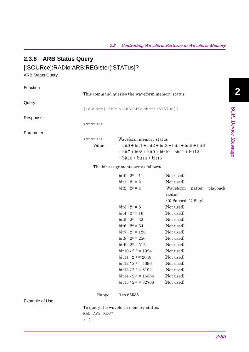
[:SOURce]:RADio:ARB:REGister[:STATus]? ARB Status Query
Function
This command queries the waveform memory status.
Query
[:SOURce]:RADio:ARB:REGister[:STATus]?
Response
<status>
Parameter
<status> Waveform memory status
Value = bit0 + bit1 + bit2 + bit3 + bit4 + bit5 + bit6 + bit7 + bit8 + bit9 + bit10 + bit11 + bit12 + bit13 + bit14 + bit15
The bit assignments are as follows:
bit0 : 20 = 1 (Not used) bit1 : 21 = 2 (Not used) bit2 : 22 = 4 Waveform patter playback
status: (0: Paused, 1: Play)
bit3 : 23 = 8 (Not used) bit4 : 24 = 16 (Not used) bit5 : 25 = 32 (Not used) bit6 : 26 = 64 (Not used) bit7 : 27 = 128 (Not used) bit8 : 28 = 256 (Not used) bit9 : 29 = 512 (Not used) bit10 : 210 = 1024 (Not used) bit11 : 211 = 2048 (Not used) bit12 : 212 = 4096 (Not used) bit13 : 213 = 8192 (Not used) bit14 : 214 = 16384 (Not used) bit15 : 215 = 32768 (Not used)
Range 0 to 65535 Example of Use
To query the waveform memory status.
RAD:ARB:REG?
> 4

Chapter 2 SCPI Device Message
2-36
2.4 Controlling Waveform Patterns in HDD Table 2.4-1 shows the device messages for controlling waveform patterns in the hard disk.
Table 2.4-1 Device messages for controlling waveform patterns in the hard disk
Function Device Messages
Copy pattern file to Hard Disk Drive
:MMEMory:COPY <device>[,<package>]
Delete Pattern file on Hard Disk Drive
:MMEMory:DELete[:NAME] <package>,<pattern>
:MMEMory:LOAD:WAVeform <package>,<pattern> Load Pattern File / Query Load Status and Wave Memory :MMEMory:LOAD:WAVeform? <package>,<pattern>
Cancel Loading :MMEMory:LOAD:WAVeform:ABORt
Pattern File Version :MMEMory:WAVeform:VERSion? <package>,<pattern>
Hard Disk Drive Size :MMEMory:WAVeform:FREE[:ALL]?

2.4 Controlling Waveform Patterns in HDD
2-37
2
SC
PI D
evice Message
2.4.1 Copy pattern file to Hard Disk Drive
:MMEMory:COPY <device>[,<package>] Copy pattern file to Hard Disk Drive
Function
This command copies the waveform pattern file from the specified drive to the internal hard disk drive. Specify a waveform pattern by a package name, which is the name of the folder that stores the waveform pattern file.
Command
:MMEMory:COPY <device>[,<package>]
Parameter
<device> Copy source drive name (A, B, D to Z, D when omitted)
<package> Copy source package name (character string) or, ROOT
Details
An error occurs when the specified drive or waveform pattern file cannot be found.
When the package name (package) is omitted, all the packages in the root folder of the specified drive will be copied.
When ROOT is specified for <package>, all the patterns in the root folder of the specified drive will be copied.
Example of Use
To copy the waveform pattern in the package "WCDMA" of Drive D to the internal hard disk. MMEM:COPY D,"WCDMA"

Chapter 2 SCPI Device Message
2-38
2.4.2 Delete Pattern file on Hard Disk Drive
:MMEMory:DELete[:NAME] <package>,<pattern> Delete Pattern file on Hard Disk Drive
Function
This command deletes the waveform pattern file on the hard disk.
Command
:MMEMory:DELete[:NAME] <package>,<pattern>
Parameter
<package> Package name (Character string)
<pattern> Pattern name (Character string)
Details
This command does not delete waveform patterns in the waveform memory.
Example of Use
To delete the "TEST" pattern in the package "WCDMA". MMEM:DEL "WCDMA","TEST"

2.4 Controlling Waveform Patterns in HDD
2-39
2
SC
PI D
evice Message
2.4.3 Load Pattern File / Query Load Status and Wave Memory
:MMEMory:LOAD:WAVeform <package>,<pattern> Load Pattern File/Check Status of Lading Pattern and Waveform Memory
Function
This command starts loading the waveform pattern from the hard disk to the waveform memory.
Command
:MMEMory:LOAD:WAVeform <package>,<pattern>
Parameter
<package> Package name (Character string)
<pattern> Pattern name (Character string)
Details
If a waveform pattern is loaded when the same waveform pattern has already been loaded, the existing waveform pattern is overwritten.
Example of Use
To start loading “TEST” pattern in package “WCDMA”. MMEM:LOAD:WAV "WCDMA","TEST"
*OPC? // Loaded when 1 is returned

Chapter 2 SCPI Device Message
2-40
:MMEMory:LOAD:WAVeform? <package>,<pattern> Load Pattern File/Check Status of Lading Pattern and Waveform Memory Query
Function
Loaded results and current status for the specified waveform pattern are returned in response to the query.
Query
:MMEMory:LOAD:WAVeform? <package>,<pattern>
Response
<status>
Parameter
<package> Package name (Character string)
<pattern> Pattern name (Character string)
<status> Status 0 Already loaded 1 Can be loaded 2 License required 3 No corresponding file 4 Insufficient waveform memory free space 5 Internal error 6 Version mismatch 7 Pattern file analysis error 8 Illegal pattern file (.wvi) 9 Exceeded number of loadable waveform pattern files 10 Exceeded number of loadable packages 11 Exceeded number of loadable waveform pattern files in
1 package
Example of Use
To start the current status of "TEST" pattern in package"WCDMA". MMEM:LOAD:WAV? "WCDMA","TEST"
> 1 // Can be loaded

2.4 Controlling Waveform Patterns in HDD
2-41
2
SC
PI D
evice Message
2.4.4 Cancel Loading
:MMEMory:LOAD:WAVeform:ABORt Cancel Loading
Function
This command cancels loading waveform patterns to waveform memory.
Command
:MMEMory:LOAD:WAVeform:ABORt
Example of Use
To cancel loading waveform patterns to waveform memory. MMEM:LOAD:WAV:ABOR

Chapter 2 SCPI Device Message
2-42
2.4.5 Pattern File Version
:MMEMory:WAVeform:VERSion? <package>,<pattern> File Version Query
Function
This command queries the waveform pattern file version on the hard disk.
Query
:MMEMory:WAVeform:VERSion? <package>,<pattern>
Response
<version>
Parameter
<package> Package name (Character string)
<pattern> Pattern name (Character string)
<version> Version number
Example of Use
To query the "TEST" pattern version number of the package "WCDMA". MMEM:WAV:VERS? "WCDMA","TEST" > 1.00

2.4 Controlling Waveform Patterns in HDD
2-43
2
SC
PI D
evice Message
2.4.6 Hard Disk Drive Size
:MMEMory:WAVeform:FREE[:ALL]? Hard Disk Drive Size Query
Function
This command queries hard disk free space information.
Query
:MMEMory:WAVeform:FREE[:ALL]?
Response
<total>,<blank>
Parameter
<total> Total hard disk size
Response unit Byte
<blank> Hard disk free space
Response unit Byte
Example of Use
To query the hard disk size. MMEM:WAV:FREE?
> 1234567890,123456789

Chapter 2 SCPI Device Message
2-44
2.5 Modulation and AWGN Settings Table 2.5-1 shows device messages for setting modulation and AWGN.
Table 2.5-1 Device messages for setting modulation and AWGN
Function Device Messages
:OUTPut:MODulation[:STATe] ON|OFF|1|0 Modulation
:OUTPut:MODulation[:STATe]?
[:SOURce]:RADio:ARB:NOISe[:STATe] ON|OFF|1|0 AWGN
[:SOURce]:RADio:ARB:NOISe[:STATe]? [:SOURce]:RADio:ARB:NOISe:CN <numeric_value><unit>
C/N Ratio [:SOURce]:RADio:ARB:NOISe:CN?
[:SOURce]:RADio:ARB:NOISe:CN:TARGet CARRier|NOISe|CONStant Target of C/N Setting
[:SOURce]:RADio:ARB:NOISe:CN:TARGet?
[:SOURce]:RADio:ARB:NOISe:CPOWer <numeric_value><unit> Carrier Power
[:SOURce]:RADio:ARB:NOISe:CPOWer?
Sampling Clock [:SOURce]:RADio:ARB:SCLock:RATE?

2.5 Modulation and AWGN Settings
2-45
2
SC
PI D
evice Message
2.5.1 Modulation
:OUTPut:MODulation[:STATe] ON|OFF|1|0 Modulation - On/Off
Function
This command sets the modulation function ON/OFF.
Command
:OUTPut:MODulation[:STATe] <on_off>
Parameter
<on_off> Modulation ON/OFF ON|1 On OFF|0 Off
Details
Fixed to OFF when no waveform pattern file is selected.
Example of Use
To set the modulation function to ON. OUTP:MOD ON
:OUTPut:MODulation[:STATe]? Modulation - On/Off Query
Function
This command queries the modulation ON/OFF status.
Query
:OUTPut:MODulation[:STATe]?
Response
<on_off>
Parameter
<on_off> Modulation ON/OFF 1 On 0 Off
Details
Fixed to OFF when no waveform pattern file is selected.
Example of Use
To query the modulation ON/OFF status. OUTP:MOD?
> 1

Chapter 2 SCPI Device Message
2-46
2.5.2 AWGN
[:SOURce]:RADio:ARB:NOISe[:STATe] ON|OFF|1|0 AWGN
Function
This command turns AWGN output ON/OFF.
Command
[:SOURce]:RADio:ARB:NOISe[:STATe] <on_off>
Parameter
<on_off> AWGN output On/Off ON|1 On OFF|0 Off
Details
Outputs a signal with AWGN added when AWGN is ON. The AWGN output function can be set to ON or OFF only when a waveform pattern file is selected and the modulation is enabled (ON).
The AWGN output function is automatically set to OFF when a waveform pattern is changed.
Example of Use
To add AWGN to output signal. RAD:ARB:NOIS ON
[:SOURce]:RADio:ARB:NOISe[:STATe]? AWGN Query
Function
This command queries the AWGN output ON/OFF status.
Query
[:SOURce]:RADio:ARB:NOISe[:STATe]?
Response
<on_off>
Parameter
<on_off> AWGN output On/Off 1 On 0 Off
Example of Use
To query the ON/OFF status of the AWGN output signal. RAD:ARB:NOIS?
> 1
2.5 Modulation and AWGN Settings
2-47
2
SC
PI D
evice Message
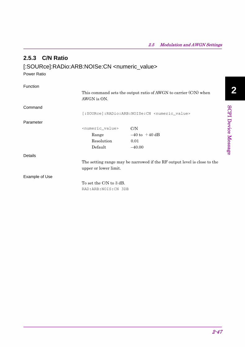
2.5.3 C/N Ratio
[:SOURce]:RADio:ARB:NOISe:CN <numeric_value> Power Ratio
Function
This command sets the output ratio of AWGN to carrier (C/N) when AWGN is ON.
Command
[:SOURce]:RADio:ARB:NOISe:CN <numeric_value>
Parameter
<numeric_value> C/N
Range –40 to +40 dB Resolution 0.01 Default –40.00
Details
The setting range may be narrowed if the RF output level is close to the upper or lower limit.
Example of Use
To set the C/N to 3 dB. RAD:ARB:NOIS:CN 3DB

Chapter 2 SCPI Device Message
2-48
[:SOURce]:RADio:ARB:NOISe:CN? Power Ratio Query
Function
This command queries the output ratio of AWGN to carrier (C/N) when AWGN is ON.
Query
[:SOURce]:RADio:ARB:NOISe:CN?
Response
<numeric_value>
Parameter
<numeric_value> C/N
Range –40 to +40 dB Resolution 0.01 Default –40.00
Example of Use
To query C/N. RAD:ARB:NOIS:CN?
> –3.00

2.5 Modulation and AWGN Settings
2-49
2
SC
PI D
evice Message
2.5.4 Target of C/N Setting
[:SOURce]:RADio:ARB:NOISe:CN:TARGet CARRier|NOISe|CONStant Target of C/N Setting
Function
This command sets the parameters to be changed when C/N is set.
Command
[:SOURce]:RADio:ARB:NOISe:CN:TARGet <target>
Parameter
<target> Parameter to be changed when C/N is set. CARRier Carrier signal NOISe NOISE CONStant Fixed output level (Carrier + AWGN)
Example of Use
To set AWGN as the parameter to be changed when C/N is set. RAD:ARB:NOIS:CN:TARG NOIS
[:SOURce]:RADio:ARB:NOISe:CN:TARGet? Target of C/N Setting Query
Function
This command queries the parameters to be changed when C/N is set.
Query
[:SOURce]:RADio:ARB:NOISe:CN:TARGet?
Response
<target>
Parameter
<target> Parameter to be changed when C/N is set. CARR Carrier signal NOIS NOISE CONS Fixed output level (Carrier + AWGN)
Example of Use
To query the parameters to be changed when C/N is set. RAD:ARB:NOIS:CN:TARG?
> NOIS

Chapter 2 SCPI Device Message
2-50
2.5.5 Carrier Power
[:SOURce]:RADio:ARB:NOISe:CPOWer <numeric_value> Carrier Power
Function
This command sets the carrier signal level when AWGN is ON.
Command
[:SOURce]:RADio:ARB:NOISe:CPOWer <numeric_value>
Parameter
<numeric_value> Carrier signal level when AWGN is ON. Range Resolution 0.01 dB Suffix code DB
Example of Use
To set the carrier signal level when AWGN is ON to –55.0 dBm. RAD:ARB:NOIS:CPOW –55
[:SOURce]:RADio:ARB:NOISe:CPOWer? Carrier Power Query
Function
This command queries the carrier signal level when AWGN is ON.
Query
[:SOURce]:RADio:ARB:NOISe:CPOWer?
Response
<numeric_value>
Parameter
<numeric_value> Carrier signal level when AWGN is ON. Range Resolution 0.01 dB
Example of Use
To query the carrier signal level when AWGN is ON. RAD:ARB:NOIS:CPOW?
> –10.00

2.5 Modulation and AWGN Settings
2-51
2
SC
PI D
evice Message
2.5.5 Sampling Clock
[:SOURce]:RADio:ARB:SCLock:RATE? Sampling Clock Query
Function
This command queries the baseband signal sampling clock.
Query
[:SOURce]:RADio:ARB:SCLock:RATE?
Response
<numeric_value>
Parameter
<numeric_value> Sampling clock Range 0.02 to 160 MHz Resolution 0.001 Hz
Example of Use
To query the sampling clock RAD:ARB:SCL:RATE?
> 80000000.000
Chapter 2 SCPI Device Message
2-52
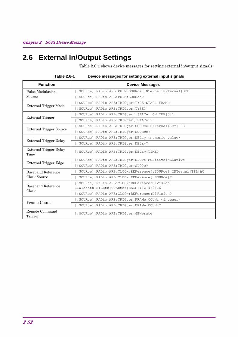
2.6 External In/Output Settings Table 2.6-1 shows device messages for setting external in/output signals.
Table 2.6-1 Device messages for setting external input signals
Function Device Messages
[:SOURce]:RADio:ARB:PULM:SOURce INTernal|EXTernal|OFF Pulse Modulation Source [:SOURce]:RADio:ARB:PULM:SOURce?
[:SOURce]:RADio:ARB:TRIGger:TYPE STARt|FRAMe External Trigger Mode
[:SOURce]:RADio:ARB:TRIGger:TYPE?
[:SOURce]:RADio:ARB:TRIGger[:STATe] ON|OFF|0|1 External Trigger
[:SOURce]:RADio:ARB:TRIGger[:STATe]?
[:SOURce]:RADio:ARB:TRIGger:SOURce EXTernal|KEY|BUS External Trigger Source
[:SOURce]:RADio:ARB:TRIGger:SOURce?
[:SOURce]:RADio:ARB:TRIGger:DELay <numeric_value> External Trigger Delay
[:SOURce]:RADio:ARB:TRIGger:DELay?
External Trigger Delay Time
[:SOURce]:RADio:ARB:TRIGger:DELay:TIME?
[:SOURce]:RADio:ARB:TRIGger:SLOPe POSitive|NEGative External Trigger Edge
[:SOURce]:RADio:ARB:TRIGger:SLOPe?
[:SOURce]:RADio:ARB:CLOCk:REFerence[:SOURce] INTernal|TTL|AC Baseband Reference Clock Source [:SOURce]:RADio:ARB:CLOCk:REFerence[:SOURce]?
[:SOURce]:RADio:ARB:CLOCk:REFerence:DIVision SIXTeenth|EIGHth|QUARter|HALF|1|2|4|8|16 Baseband Reference
Clock [:SOURce]:RADio:ARB:CLOCk:REFerence:DIVision?
[:SOURce]:RADio:ARB:TRIGger:FRAMe:COUNt <integer> Frame Count
[:SOURce]:RADio:ARB:TRIGger:FRAMe:COUNt?
Remote Command Trigger
[:SOURce]:RADio:ARB:TRIGger:GENerate

2.6 External In/Output Settings
2-53
2
SC
PI D
evice Message
2.6.1 Pulse Modulation Source
[:SOURce]:RADio:ARB:PULM:SOURce INTernal|EXTernal|OFF Pulse Modulation Source
Function
This command sets the pulse modulation signal source.
Command
[:SOURce]:RADio:ARB:PULM:SOURce <source>
Parameter
<source> Pulse modulation signal source. INTernal Internal signal EXTernal External input signal OFF No pulse modulation
Example of Use
To set the pulse modulation signal source to internal signal. RAD:ARB:PULM:SOUR INT
[:SOURce]:RADio:ARB:PULM:SOURce? Pulse Modulation Source Query
Function
This command queries the pulse modulation signal source.
Query
[:SOURce]:RADio:ARB:PULM:SOURce?
Response
<source>
Parameter
<source> Pulse modulation signal source. INT Internal signal EXT External input signal OFF No pulse modulation
Example of Use
To query the status of the pulse modulation signal source. RAD:ARB:PULM:SOUR?
> INT

Chapter 2 SCPI Device Message
2-54
2.6.2 External Trigger Mode
[:SOURce]:RADio:ARB:TRIGger:TYPE STARt|FRAMe External Trigger - Mode
Function
This command sets the external trigger operation mode.
Command
[:SOURce]:RADio:ARB:TRIGger:TYPE <mode>
Parameter
<mode> External trigger operation mode. STARt Start trigger FRAMe Frame trigger
Example of Use
To set the external trigger operation mode to start trigger. RAD:ARB:TRIG:TYPE START
[:SOURce]:RADio:ARB:TRIGger:TYPE? External Trigger - Mode Query
Function
This command queries the external trigger operation mode.
Query
[:SOURce]:RADio:ARB:TRIGger:TYPE?
Response
<mode>
Parameter
<mode> External trigger operation mode. STAR Start trigger FRAM Frame trigger
Example of Use
To query the external trigger operation mode. RAD:ARB:TRIG:TYPE?
> STAR

2.6 External In/Output Settings
2-55
2
SC
PI D
evice Message
2.6.3 External Trigger
[:SOURce]:RADio:ARB:TRIGger[:STATe] ON|OFF|0|1 External Trigger - On/Off
Function
This command sets the external trigger ON/OFF.
Command
[:SOURce]:RADio:ARB:TRIGger[:STATe] <on_off>
Parameter
<on_off> External trigger On/Off ON|1 On OFF|0 Off
Example of Use
To enable the external trigger. RAD:ARB:TRIG ON
[:SOURce]:RADio:ARB:TRIGger[:STATe]? External Trigger - On/Off Query
Function
This command queries the external trigger ON/OFF status.
Query
[:SOURce]:RADio:ARB:TRIGger[:STATe]?
Response
<on_off>
Parameter
<on_off> External trigger On/Off 1 On 0 Off
Example of Use
To query the external trigger ON/OFF status. RAD:ARB:TRIG?
> 0

Chapter 2 SCPI Device Message
2-56
2.6.4 External Trigger Source
[:SOURce]:RADio:ARB:TRIGger:SOURce EXTernal|KEY|BUS Start Trigger Delay Source
Function
This command sets the signal source of the external trigger.
Command
[:SOURce]:RADio:ARB:TRIGger:SOURce <source>
Parameter
<source> External trigger signal source EXTernal External input signal KEY Trigger key input
BUS Remote Command
.
Example of Use
To set the signal source of the external trigger to the external input signal. RAD:ARB:TRIG:SOUR EXT
[:SOURce]:RADio:ARB:TRIGger:SOURce? Start Trigger Delay Source Query
Function
This command queries the signal source of the external trigger.
Query
[:SOURce]:RADio:ARB:TRIGger:SOURce?
Response
<source>
Parameter
<source> External trigger signal source EXT External input signal KEY Trigger key input
BUS Remote Command .
Example of Use
To query the external trigger ON/OFF status. RAD:ARB:TRIG:SOUR?
> EXT

2.6 External In/Output Settings
2-57
2
SC
PI D
evice Message
2.6.5 External Trigger Delay
[:SOURce]:RADio:ARB:TRIGger:DELay <numeric_value> Start Trigger Delay
Function
This command sets the RF signal output timing in symbol or chip rate units of each system (determined by the overrate).
Command
[:SOURce]:RADio:ARB:TRIGger:DELay <numeric_value>
Parameter
<numeric_value> Start trigger delay time Range Varies depending on the selected waveform
pattern. Resolution Varies depending on the selected waveform
pattern. Default 0 Unit None (Symbol or chip)
Example of Use
To set the start trigger delay time to 30 chips. RAD:ARB:TRIG:DEL 30

Chapter 2 SCPI Device Message
2-58
[:SOURce]:RADio:ARB:TRIGger:DELay? Start Trigger Delay Query
Function
This command queries the RF signal output timing in symbol or chip rate units of each system (determined by the overrate).
Query
[:SOURce]:RADio:ARB:TRIGger:DELay?
Response
<numeric_value>
Parameter
<numeric_value> Start trigger delay time
Range Varies depending on the selected waveform pattern.
Resolution Varies depending on the selected waveform pattern.
Default 0 Unit None (Symbol or chip)
Example of Use
To query the external trigger ON/OFF status. RAD:ARB:TRIG:DEL?
> 30

2.6 External In/Output Settings
2-59
2
SC
PI D
evice Message
2.6.6 External Trigger Delay Time
[:SOURce]:RADio:ARB:TRIGger:DELay:TIME? Start Trigger Delay Time Query
Function
This command queries a value computed by converting the output timing of RF signals into time.
Query
[:SOURce]:RADio:ARB:TRIGger:DELay:TIME?
Response
<numeric_value>
Parameter
<numeric_value> Start trigger delay time Unit s
Example of Use
To query the output timing of the external trigger. RAD:ARB:TRIG:DEL:TIME?
> 6.50E-8
Chapter 2 SCPI Device Message
2-60
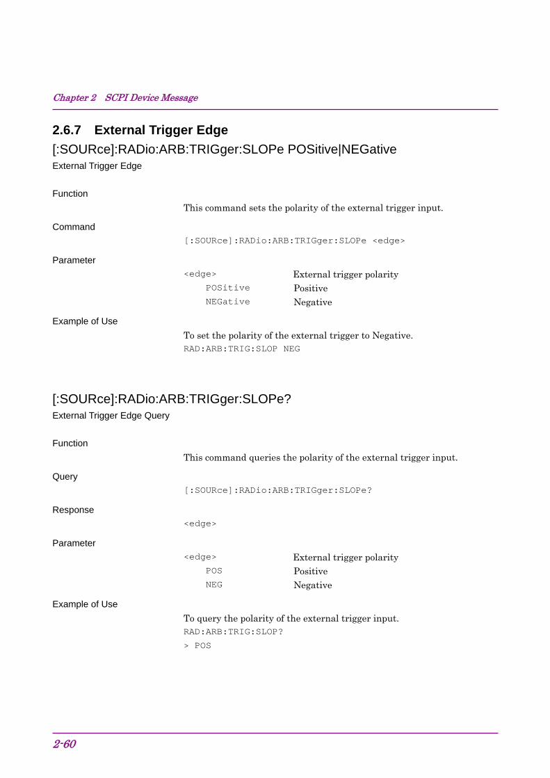
2.6.7 External Trigger Edge
[:SOURce]:RADio:ARB:TRIGger:SLOPe POSitive|NEGative External Trigger Edge
Function
This command sets the polarity of the external trigger input.
Command
[:SOURce]:RADio:ARB:TRIGger:SLOPe <edge>
Parameter
<edge> External trigger polarity POSitive Positive NEGative Negative
Example of Use
To set the polarity of the external trigger to Negative. RAD:ARB:TRIG:SLOP NEG
[:SOURce]:RADio:ARB:TRIGger:SLOPe? External Trigger Edge Query
Function
This command queries the polarity of the external trigger input.
Query
[:SOURce]:RADio:ARB:TRIGger:SLOPe?
Response
<edge>
Parameter
<edge> External trigger polarity POS Positive NEG Negative
Example of Use
To query the polarity of the external trigger input. RAD:ARB:TRIG:SLOP?
> POS

2.6 External In/Output Settings
2-61
2
SC
PI D
evice Message
2.6.8 Baseband Reference Clock Source
[:SOURce]:RADio:ARB:CLOCk:REFerence[:SOURce] INTernal|EXTernal Baseband Reference Clock Source
Function
This command sets baseband signal reference clock.
Command
[:SOURce]:RADio:ARB:CLOCk:REFerence[:SOURce] <source>
Parameter
<source> Baseband signal reference clock INTernal Internal signal (Default) EXTernal External input signal
Example of Use
To set the baseband signal reference clock to external input signal. RAD:ARB:CLOC:REF EXT
[:SOURce]:RADio:ARB:CLOCk:REFerence[:SOURce]? Baseband Reference Clock Source Query
Function
This command queries baseband signal reference clock.
Query
[:SOURce]:RADio:ARB:CLOCk:REFerence[:SOURce]?
Response
<source>
Parameter
<source> Baseband signal reference clock INT Internal signal (Default) EXT External input signal
Example of Use
To query baseband signal reference clock. RAD:ARB:CLOC:REF?
> INT

Chapter 2 SCPI Device Message
2-62
2.6.9 Baseband Reference Clock
[:SOURce]:RADio:ARB:CLOCk:REFerence:DIVision
SIXTeenth|EIGHth|QUARter|HALF|1|2|4|8|16 Baseband Reference Clock
Function
This command sets the baseband signal reference clock frequency in magnification ratio based on the sampling clock.
Command
[:SOURce]:RADio:ARB:CLOCk:REFerence:DIVision <clock>
Parameter
<clock> Baseband signal reference clock SIXTeenth Sampling Clock × 1/16 EIGHth Sampling Clock × 1/8 QUARter Sampling Clock × 1/4 HALF Sampling Clock × 1/2 1 Sampling Clock × 1 2 Sampling Clock × 2 4 Sampling Clock × 4 8 Sampling Clock × 8 16 Sampling Clock × 16
The setting range is as shown in the following table.
Baseband reference clock setting range
Baseband Reference Clock Setting Sampling Clock [MHz] 16 8 4 2 1 1/2 1/4 1/8 1/16
0.02≤f<0.024414062 0.024414062≤f<0.048828125 0.048828125≤f<0.09765625
0.09765625≤f<0.1953125 0.1953125≤f<2.5
2.5≤f<5
5≤f<10
10≤f<20
20≤f<40
40≤f<80
80≤f<160
Example of Use
To set the baseband signal reference lock frequency to sampling clock 2. RAD:ARB:CLOC:REF:DIV 2

2.6 External In/Output Settings
2-63
2
SC
PI D
evice Message
[:SOURce]:RADio:ARB:CLOCk:REFerence:DIVision? Baseband Reference Clock Query
Function
This command queries the reference clock frequency of the baseband signal.
Query
[:SOURce]:RADio:ARB:CLOCk:REFerence:DIVision?
Response
<clock>
Parameter
<clock> Baseband signal reference clock SIXT Sampling Clock × 1/16 EIGH Sampling Clock × 1/8 QUAR Sampling Clock × 1/4 HALF Sampling Clock × 1/2 1 Sampling Clock × 1 2 Sampling Clock × 2 4 Sampling Clock × 4 8 Sampling Clock × 8 16 Sampling Clock × 16
Example of Use
To query the reference clock frequency of the baseband signal. RAD:ARB:CLOC:REF:DIV?
> 1

Chapter 2 SCPI Device Message
2-64
2.6.10 Frame Count
[:SOURce]:RADio:ARB:TRIGger:FRAMe:COUNt <integer> Frame Count
Function
This command sets the Frame Count from the Signal Generator option.
Command
[:SOURce]:RADio:ARB:TRIGger:FRAMe:COUNt <integer>
Parameter
<integer>,n Specifying the output frame count
Range 1 to 32767 Resolution 1 Default 1
Example of Use
To set the output frame count to 10. RAD:ARB:TRIG:FRAM:COUN 10
[:SOURce]:RADio:ARB:TRIGger:FRAMe:COUNt? Frame Count Query
Function
This command queries the Frame Count from the Signal Generator option.
Query
[:SOURce]:RADio:ARB:TRIGger:FRAMe:COUNt?
Response
<integer>,n
Parameter
<integer> Number of output frames Range 1 to 32767 Resolution 1
Example of Use
To query the Frame Count from the Signal Generator option. RAD:ARB:TRIG:FRAM:COUN?
> 10

2.6 External In/Output Settings
2-65
2
SC
PI D
evice Message
2.6.11 Remote Command Trigger
[:SOURce]:RADio:ARB:TRIGger:GENerate Remote Command Trigger
Function
This command triggers the output of waveform pattern. This becomes available when Trigger Source is BUS.
Command
[:SOURce]:RADio:ARB:TRIGger:GENerate
Example of Use
To trigger the output of waveform pattern. RAD:ARB:TRIG:GEN

Chapter 2 SCPI Device Message
2-66
2.7 External output signal settings Table 2.7-1 shows device messages for setting external output signals.
Table 2.7-1 Device messages for setting external output signals
Function Device Messages
[:SOURce]:RADio:ARB:MARKer1|2|3:POLarity POSitive|NEGative Marker Polarity
[:SOURce]:RADio:ARB:MARKer1|2|3:POLarity?
[:SOURce]:RADio:ARB:MARKer1|2|3:EDIT[:STATe] ON|OFF|1|0|PATSync Marker Edit [:SOURce]:RADio:ARB:MARKer1|2|3:EDIT[:STSTe]? [:SOURce]:RADio:ARB:MARKer1|2|3:EDIT:CYCLe <numeric_value>
Marker Pulse Cycle Value [:SOURce]:RADio:ARB:MARKer1|2|3:EDIT:CYCLe?
[:SOURce]:RADio:ARB:MARKer1|2|3:EDIT:OFFSet <numeric_value> Marker Pulse Start Offset Value [:SOURce]:RADio:ARB:MARKer1|2|3:EDIT:OFFSet?
[:SOURce]:RADio:ARB:MARKer1|2|3:EDIT:WIDTh <numeric_value> Marker Pulse Width Value [:SOURce]:RADio:ARB:MARKer1|2|3:EDIT:WIDTh?

2.7 External output signal settings
2-67
2
SC
PI D
evice Message
2.7.1 Marker Polarity
[:SOURce]:RADio:ARB:MARKer1|2|3:POLarity POSitive|NEGative Marker Polarity
Function
This command sets the polarity of the external output marker signal.
Command
[:SOURce]:RADio:ARB:MARKer[n]:POLarity <polarity>
Parameter
<n> Marker type 1 Marker 1 2 Marker 2 3 Marker 3
<polarity> Polarity POSitive Positive (Positive polarity) NEGative Negative (Negative polarity)
Example of Use
To set the polarity of Marker 1 to negative. RAD:ARB:MARK1:POL NEG

Chapter 2 SCPI Device Message
2-68
[:SOURce]:RADio:ARB:MARKer1|2|3:POLarity? Marker Polarity Query
Function
This command queries the polarity of the external output marker signal.
Query
[:SOURce]:RADio:ARB:MARKer[n]:POLarity?
Response
<polarity>
Parameter
<n> Marker type 1 Marker 1 2 Marker 2 3 Marker 3
<polarity> Polarity POS Positive (Positive polarity) NEG Negative (Negative polarity)
Example of Use
To query the polarity of Marker 1. RAD:ARB:MARK1:POL?
> POS

2.7 External output signal settings
2-69
2
SC
PI D
evice Message
2.7.2 Marker Edit
[:SOURce]:RADio:ARB:MARKer1|2|3:EDIT[STATe] ON|OFF|1|0|PATSync Marker Edit
Function
This command specifies the user setting mode for the external output marker.
Command
[:SOURce]:RADio:ARB:MARKer[n]:EDIT[:STATe] <mode>
Parameter
<n> Marker type 1 Marker 1 2 Marker 2 3 Marker 3
<mode> User setting mode ON|1 Outputs the user setting marker. OFF|0 Outputs the marker previously recorded in the
waveform pattern. PATSync Outputs the marker at the start of the
waveform pattern.
Details
OFF|0 can be set only when a waveform with a resolution of 14 bit IQ data is selected. When a waveform with a resolution of 15 or 16 bits is selected, the following restriction applies:
15-bit resolution: Markers 2 and 3 cannot be set to OFF|0. 16-bit resolution: Markers 1 and 3 cannot be set to OFF|0.
Example of Use
To set the Marker 1 to user setting mode. RAD:ARB:MARK1:EDIT ON

Chapter 2 SCPI Device Message
2-70
[:SOURce]:RADio:ARB:MARKer1|2|3:EDIT[:STSTe]? Marker Edit Query
Function
This command queries the user setting mode for the external output marker.
Query
[:SOURce]:RADio:ARB:MARKer[n]:EDIT[:STSTe]?
Response
<mode>
Parameter
<n> Marker type 1 Marker 1 2 Marker 2 3 Marker 3
<mode> User setting mode 1 Outputs the user setting marker. 0 Outputs the marker previously recorded in the
waveform pattern. PATS Outputs the marker at the start of the waveform
pattern.
Example of Use
To query the setting mode for the external output marker of Marker 1. RAD:ARB:MARK1:EDIT?
> 1

2.7 External output signal settings
2-71
2
SC
PI D
evice Message
2.7.3 Marker Pulse Cycle Value
[:SOURce]:RADio:ARB:MARKer1|2|3:EDIT:CYCLe <numeric_value> Marker Edit Mode Cycle Value
Function
This command sets the output pulse cycle when the external output marker is set to the user setting marker.
Command
[:SOURce]:RADio:ARB:MARKer[n]:EDIT:CYCLe <numeric_value>
Parameter
<n> Marker type 1 Marker 1 2 Marker 2 3 Marker 3
<numeric_value> Output pulse cycle
Example of Use
To set the output pulse cycle of Marker 1 to 200. RAD:ARB:MARK1:EDIT:CYCL 200
Chapter 2 SCPI Device Message
2-72
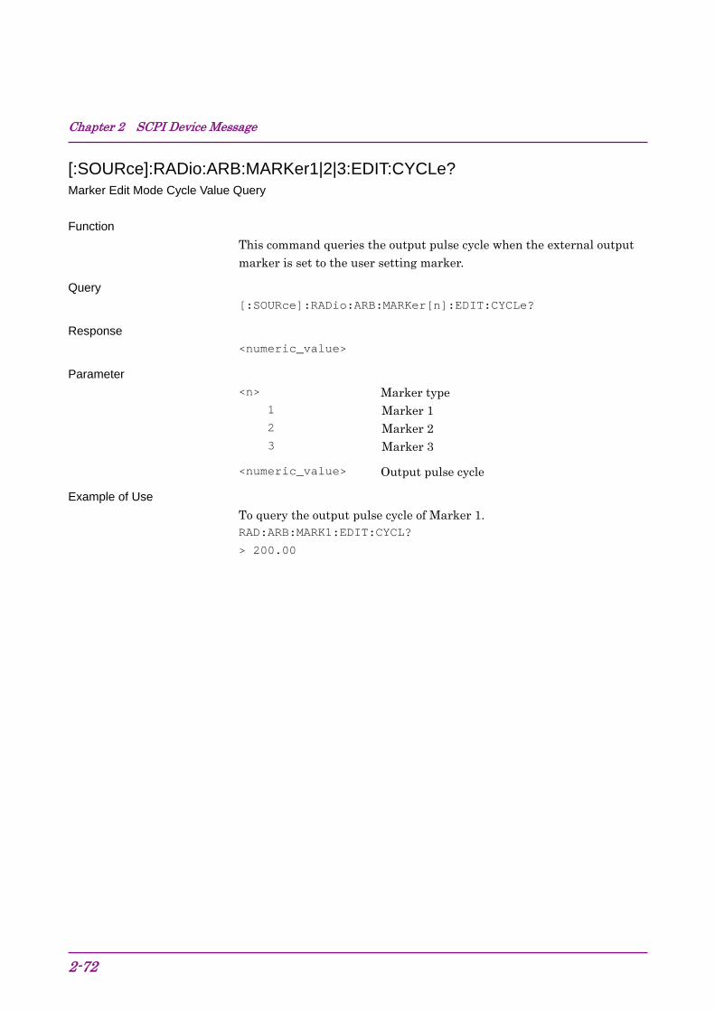
[:SOURce]:RADio:ARB:MARKer1|2|3:EDIT:CYCLe? Marker Edit Mode Cycle Value Query
Function
This command queries the output pulse cycle when the external output marker is set to the user setting marker.
Query
[:SOURce]:RADio:ARB:MARKer[n]:EDIT:CYCLe?
Response
<numeric_value>
Parameter
<n> Marker type 1 Marker 1 2 Marker 2 3 Marker 3
<numeric_value> Output pulse cycle
Example of Use
To query the output pulse cycle of Marker 1. RAD:ARB:MARK1:EDIT:CYCL?
> 200.00
2.7 External output signal settings
2-73
2
SC
PI D
evice Message
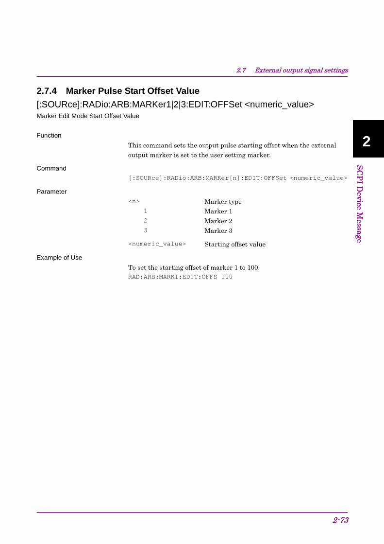
2.7.4 Marker Pulse Start Offset Value
[:SOURce]:RADio:ARB:MARKer1|2|3:EDIT:OFFSet <numeric_value> Marker Edit Mode Start Offset Value
Function
This command sets the output pulse starting offset when the external output marker is set to the user setting marker.
Command
[:SOURce]:RADio:ARB:MARKer[n]:EDIT:OFFSet <numeric_value>
Parameter
<n> Marker type 1 Marker 1 2 Marker 2 3 Marker 3
<numeric_value> Starting offset value
Example of Use
To set the starting offset of marker 1 to 100. RAD:ARB:MARK1:EDIT:OFFS 100

Chapter 2 SCPI Device Message
2-74
[:SOURce]:RADio:ARB:MARKer1|2|3:EDIT:OFFSet? Marker Edit Mode Start Offset Value Query
Function
This command queries the output pulse starting offset when the external output marker is set to the user setting marker.
Query
[:SOURce]:RADio:ARB:MARKer[n]:EDIT:OFFSet?
Response
<numeric_value>
Parameter
<n> Marker type 1 Marker 1 2 Marker 2 3 Marker 3
<numeric_value> Starting offset value
Example of Use
To query the starting offset value of Marker 1. RAD:ARB:MARK1:EDIT:OFFS?
> 100.00

2.7 External output signal settings
2-75
2
SC
PI D
evice Message
2.7.5 Marker Pulse Width Value
[:SOURce]:RADio:ARB:MARKer1|2|3:EDIT:WIDTh <numeric_value> Marker Edit Mode Width Value
Function
This command sets the output pulse width when the external output marker is set to the user setting marker.
Command
[:SOURce]:RADio:ARB:MARKer[n]:EDIT:WIDTh <numeric_value>
Parameter
<n> Marker type 1 Marker 1 2 Marker 2 3 Marker 3
<numeric_value> Pulse width
Example of Use
To set the pulse width of marker 1 to 50. RAD:ARB:MARK1:EDIT:WIDT 50

Chapter 2 SCPI Device Message
2-76
[:SOURce]:RADio:ARB:MARKer1|2|3:EDIT:WIDTh? Marker Edit Mode Width Value Query
Function
This command queries the output pulse width when the external output marker is set to the user setting marker.
Query
[:SOURce]:RADio:ARB:MARKer[n]:EDIT:WIDTh?
Response
<numeric_value>
Parameter
<n> Marker type 1 Marker 1 2 Marker 2 3 Marker 3
<numeric_value> Pulse width
Example of Use
To query the pulse width of marker 1. RAD:ARB:MARK1:EDIT:WIDT?
> 50.00

2.8 Setting Trigger to Be Output to SG Marker of SA/SPA
2-77
2
SC
PI D
evice Message
2.8 Setting Trigger to Be Output to SG Marker of
SA/SPA Table 2.8-1 shows the device messages for setting the trigger to be output to the SG marker of SA/SPA.
Table 2.8-1 Device messages for setting the trigger to be output to the SG marker of SA/SPA
Function Device Messages
:ROUTe:SATRigger[:OUTPut] MARKer1|2|3|PATSync SA Trigger Out
:ROUTe:SATRigger[:OUTPut]?
2.8.1 SA Trigger Out
:ROUTe:SATRigger[:OUTPut] MARKer1|2|3|PATSync SA Trigger Out
Function
This command selects the type of the trigger to be output to the SG marker of SA/SPA.
Command
:ROUTe:SATRigger[:OUTPut] <triggertoSA>
Parameter
<triggertoSA> Output trigger MARKer1 Marker 1 MARKer2 Marker 2 MARKer3 Marker 3 PATSync A marker synchronized with the top of pattern
Example of Use
To select the type of the trigger to be output to the SG marker of SA/SPA. ROUT:SATR MARK1

Chapter 2 SCPI Device Message
2-78
:ROUTe:SATRigger[:OUTPut]? SA Trigger Out Query
Function
This command queries the type of the trigger to be output to the SG marker of SA/SPA.
Query
:ROUTe:SATRigger[:OUTPut]?
Response
<triggertoSA>
Parameter
<triggertoSA> Output trigger MARK1 Marker 1 MARK2 Marker 2 MARK3 Marker 3 PATS A marker synchronized with the top of pattern
Example of Use
To query the type of the trigger to be output to the SG marker of SA/SPA. ROUT:SATR?
> MARK1

2.9 Display Settings
2-79
2
SC
PI D
evice Message
2.9 Display Settings Table 2.9-1 shows the device messages for setting the display function.
Table 2.9-1 Device messages for setting the display function
Function Device Messages
:DISPlay[:WINDow]:POSition TOP|BOTTom SG Window Position
:DISPlay[:WINDow]:POSition?
2.9.1 SG Window Position
:DISPlay[:WINDow]:POSition TOP|BOTTom SG Window Position
Function
This command switches the display position of the Signal Generator screen.
Command
:DISPlay[:WINDow]:POSition <position>
Parameter
<position> Display position TOP Top BOTTom Bottom
Example of Use
To display the Signal Generator screen at the lower portion. DISP:POS BOTT

Chapter 2 SCPI Device Message
2-80
:DISPlay[:WINDow]:POSition? SG Window Position Query
Function
This command queries the display position of the Signal Generator screen.
Query
:DISPlay[:WINDow]:POSition?
Response
<position>
Parameter
<position> Display position TOP Top BOTT Bottom
Example of Use
To query the display position of the Signal Generator screen. DISP:POS?
> BOTT

2.10 Other Settings
2-81
2
SC
PI D
evice Message
2.10 Other Settings Table 2.10-1 shows the device messages for setting other functions.
Table 2.10-1 Device Messages for Other Settings
Function Device Messages
SG Status :STATus:ERRor?
2.10.1 SG Status
:STATus:ERRor? SG Status Query
Function
This command queries the SG operating status (normal/malfunction) when the application to be operated is SG.
Query
:STATus:ERRor?
Response
<status>
Parameter
<status> Measurement status
Value = bit0 + bit1 + bit2 + bit3 + bit4 + bit5 + bit6 + bit7 + bit8 + bit9 + bit10 + bit11 + bit12 + bit13 + bit14 + bit15
The bit assignments are as follows:
bit0 : 20 = 1 Lock malfunction occurred while external reference signal source was being used
bit1 : 21 = 2 ALC circuit is abnormal. bit2 : 22 = 4 Outside level accuracy
assurance bit3 : 23 = 8 (Not used) bit4 : 24 = 16 (Not used) bit5 : 25 = 32 (Not used) bit6 : 26 = 64 (Not used) bit7 : 27 = 128 (Not used) bit8 : 28 = 256 (Not used) bit9 : 29 = 512 (Not used) bit10 : 210 = 1024 (Not used) bit11 : 211 = 2048 (Not used)

Chapter 2 SCPI Device Message
2-82.
bit12 : 212 = 4096 (Not used) bit13 : 213 = 8192 (Not used) bit14 : 214 = 16384 (Not used) bit15 : 215 = 32768 (Not used)
Range 0 to 65535
Details
0 is returned if the operation is normal.
Example of Use
To query the current operation status. STAT:ERR?
> 0

Chapter 3 Native Device Message List
3-1
3
Native D
evice Message L
ist
This chapter describes remote control commands for executing functions of this application using a list organized by functions. Refer to Chapter 4 “Device Message Details” for detailed specifications for each command. Refer to the MS2690A/MS2691A/MS2692A or MS2830A Signal Analyzer Operation Manual (Mainframe Remote Control) for detailed specifications on IEEE488.2 common device messages and application common device messages.
3.1 IEEE488.2 Common Device Messages .................... 3-2 3.2 Application Common Device Messages .................... 3-4 3.3 Frequency Settings.................................................... 3-7 3.4 Level Settings ............................................................ 3-8 3.5 Controlling Waveform Patterns in Waveform
Memory ...................................................................... 3-10 3.6 Controlling Waveform Patterns in HDD ..................... 3-12 3.7 Modulation and AWGN Settings ................................ 3-13 3.8 External Input Signal Settings.................................... 3-14 3.9 External Output Signal Settings................................. 3-16 3.10 Setting Trigger to Be Output to SG Marker of
SA/SPA ...................................................................... 3-17 3.11 Display Settings ......................................................... 3-18
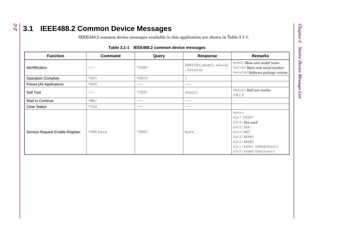
Chapter 3 N
ative Device M
essage List
3-2 3.1 IEEE488.2 Common Device Messages IEEE488.2 common device messages available in this application are shown in Table 3.1-1.
Table 3.1-1 IEEE488.2 common device messages
Function Command Query Response Remarks
Identification --- *IDN? ANRITSU,model,serial,version
model: Main unit model name serial: Main unit serial number version: Software package version
Operation Complete *OPC *OPC? 1
Preset (All Application) *RST --- ---
Self Test --- *TST? result Result: Self test results
= 0 | 1
Wait to Continue *WAI --- ---
Clear Status *CLS --- ---
Service Request Enable Register *SRE byte *SRE? byte
byte =
bit7 : EESB7
bit6 : Not used
bit5 : ESB
bit4 : MAV
bit3 : EESB3
bit2 : EESB2
bit1 : EESB1 (ERROR Event) bit0 : EESB0 (END Event)
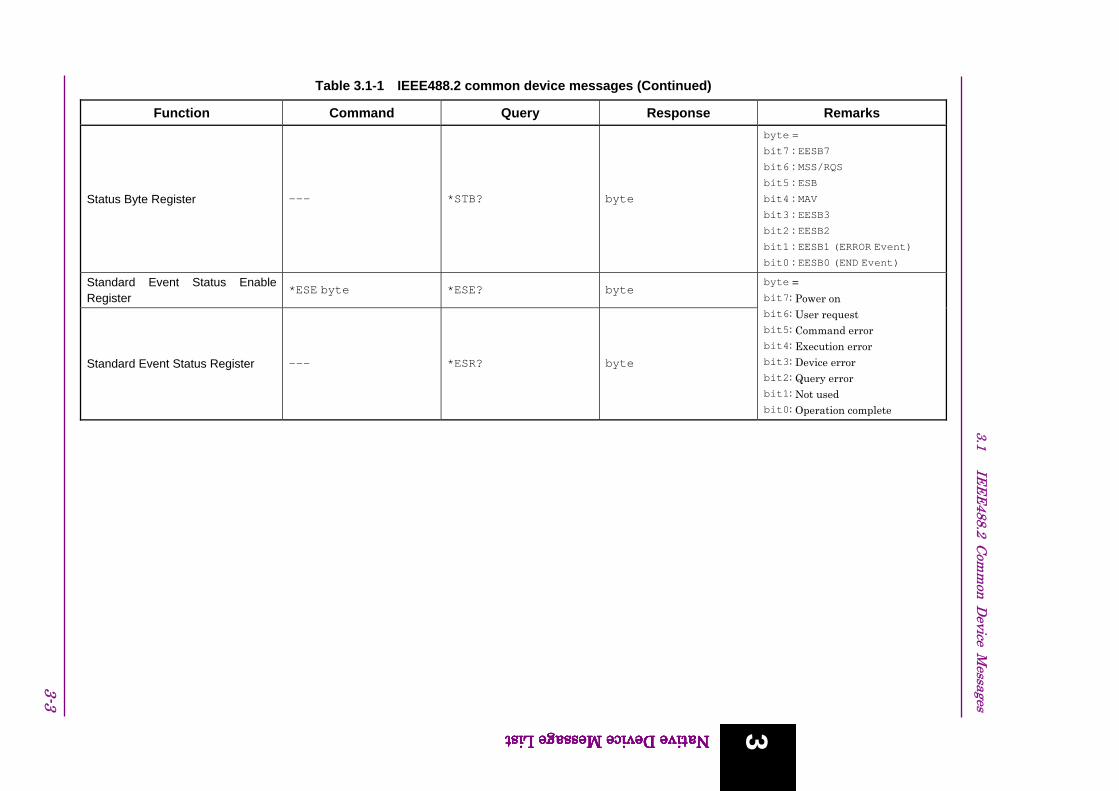
Table 3.1-1 IEEE488.2 common device messages (Continued)
Function Command Query Response Remarks
Status Byte Register --- *STB? byte
byte =
bit7 : EESB7
bit6 : MSS/RQS
bit5 : ESB
bit4 : MAV
bit3 : EESB3
bit2 : EESB2
bit1 : EESB1 (ERROR Event) bit0 : EESB0 (END Event)
Standard Event Status Enable Register
*ESE byte *ESE? byte
Standard Event Status Register --- *ESR? byte
byte =
bit7: Power on
bit6: User request
bit5: Command error
bit4: Execution error
bit3: Device error
bit2: Query error
bit1: Not used bit0: Operation complete
3-3
3.1 IE
EE
488.2 Com
mon D
evice Messages
Native Device Message List
3Native Device Message List 3Native Device Message List 3Native Device Message List
3

Chapter 3 N
ative Device M
essage List
3-4 3.2 Application Common Device Messages Application common device messages available in this application are shown in Table 3.2-1.
Table 3.2-1 Application common device messages
Function Command Query Response Remarks
Application Switch SYS apl,window SYS? apl status,window
apl: Application name
= SG
window: Window status = ACT | INACT | MIN | NON
status: Application execution status
= CURRENT | IDLE | RUN | UNLOAD
Preset (All Application) *RST --- ---
PRE --- --- Preset (Active Application only)
INI --- ---
System Restart REBOOT --- ---
LCD Power DISPLAY on_off DISPLAY? on_off
Error Display Mode REMDISP mode REMDISP? mode mode : Display mode
= NORMAL | REMAIN |
REMAIN_LAST
SVPRM --- ---
Save Parameter SVPRM fname,dev --- ---
fname : Filename
dev Drive name = D | E | ...
RCPRM fname,dev,apl --- ---
Recall Parameter RCPRM fname,dev --- ---
fname : Filename
dev Drive name
= D | E | ...
apl : Target application = ALL | CURR

Table 3.2-1 Application common device messages (Continued)
3-5
3.2 A
pplication Com
mon D
evice Messages
Native Device Message List
Function Command Query Response Remarks
PRINT --- --- Hard Copy
PRINT fname,dev --- ---
fname : Filename
dev Drive name = D | E | ...
PMOD format PMOD? format Hard Copy Mode
PMOD PMOD? BMP
format : Specifies file format
= BMP | PNG
Extended End Event Status Enable Register
ESE0 n ESE0? byte
Extended End Event Status Register
--- ESR0? byte
byte = Status bit
bit7 : Not used
bit6 : Not used
bit5 : Not used
bit4 : Not used
bit3 : Not used
bit2 : Not used
bit1 : Not used bit0 : Signal Generator
Extended Error Event Status Enable Register
ESE1 n ESE1? byte
Extended Error Event Status Register
--- ESR1? byte
byte = Status bit
bit7 : Not used
bit6 : Not used
bit5 : Not used
bit4 : Not used
bit3 : Not used
bit2 : Not used
bit1 : Not used bit0 : Signal Generator
3Native Device Message List
3

Chapter 3 N
ative Device M
essage List
3-6
Function Command Query Response Remarks
END Event Status Enable Register ESEEND n ESEEND? byte
END Event Status Register --- ESREND? byte
byte = Status bit
bit7 : Not used
bit6 : Not used
bit5 : Waveform pattern copied
bit4 : Waveform pattern loaded
bit3 : Not used
bit2 : Not used
bit1 : Not used bit0 : Not used
ERROR Event Status Enable Register
ESEERR n ESEERR? byte
ERROR Event Status Register --- ESRERR? byte
byte = Status bit
bit7 : Not used
bit6 : Not used
bit5 : Waveform pattern copy errorbit4 : Waveform pattern load errorbit3 : Not used
bit2 : Not used
bit1 : Not used bit0 : Not used
Table 3.2-1 Application common device messages (Continued)

3.3 Frequency Settings Device messages for setting frequencies are shown in Table 3.3-1.
Table 3.3-1 Frequency setting messages
Function Command Query Response Remarks
Frequency FREQ freq FREQ? freq
Frequency Step Value FIS freq FIS? freq
Frequency Step Up/Down FRS up_down --- ---
RF Spectrum SPREV mode SPREV? mode mode: Invert output waveform
= ON | OFF
3-7
3.3 F
requency Settings
Native Device Message List 3Native Device Message List
3

Chapter 3 N
ative Device M
essage List
3-8 3.4 Level Settings Device messages for setting levels are shown in Tables 3.4-1 to 3.4-2.
Table 3.4-1 Level setting messages
Function Command Query Response Remarks
RF Output LVL on_off LVL? on_off
Output Level OLVL level OLVL? unit level unit: Units
= DBM | DBU
Output Level Step Value OIS level OIS? level
Output Level Step OLS up_down --- --- up_down : Up/Down
= UP | DOWN | DN
Output Level Unit OLU unit OLU? unit: Units
= DBM | DBU
Volt Unit Display VDSPL unit VDSPL? unit unit: Voltage unit display system
= EMF | TERM
Level Offset OOF on_off OOF? on_off
Level Offset Value OOS level OOS? level
Relative Level ORL on_off ORL? on_off
Relative Level Value ORLV level ORLV? level
Reference of Relative Level --- ORLR? level

Table 3.4-1 Level setting messages (Continued)
Function Command Query Response Remarks
SG Level Calibration LVLCAL --- ---
ALC Status --- ALCSTT? status status: ALC status = NORMAL | ALCALARM
Unleveled Status -- LVLACCSTT? unleveled unleveled: Output level accuracy
status
= NORMAL | UNLEVELED
Level Status List --- LVLSTTLST? unit,offset,unleveled,INTALC,CONTOFF,relative,NORMAL
unit: Voltage unit display
= EMF | TERM
offset: Level offset
= OFFSETON | OFFSETOFF
unleveled: Output level accuracy
status
= NORMAL | UNLEVELED INTALC :Fixed Value
CONTOFF : Fixed Value
relative: Relative output mode = RELON | RELOFF
NORMAL : Fixed Value
3-9
3.4 L
evel Settings
Native Device Message List 3Native Device Message List
3

Chapter 3 N
ative Device M
essage List
3-10 3.5 Controlling Waveform Patterns in Waveform Memory Tables 3.5-1 and Table 3.5-2 show the device messages for controlling waveform patterns loaded into the waveform memory.
Table 3.5-1 Controlling waveform patterns in waveform memory
Function Command Query Response Remarks
Waveform Restart DLRES --- ---
Waveform Status --- PATRUNSTT? status status : playback status
= STOP | PLAY
LOADEDFILESEL package,pattern
LOADEDFILESEL? package,pattern Select Pattern file on Wave Memory
PAT package,pattern PAT? package,pattern
DELFILEWM package,pattern
--- --- Delete Pattern file on Wave Memory DELPATWM
package,pattern --- ---
package : package name
pattern : pattern name
Delete All Pattern files on Wave Memory (Clear Wave Memory)
DELFILEWM ALL --- ---
--- LOADEDFILENUM? number Number of loaded pattern files
--- PATNUM? number
number : Waveform pattern
number

Function Command Query Response Remarks
--- LOADEDFILENAME? number
package,pattern
List of Loaded Pattern Files
--- PATNAME? number package,pattern
number : Waveform pattern number
package : package name
pattern : pattern name
Wave Memory Size --- WMSPC? blank1,blank2,total
blank1 : Free memory space(byte)
blank2 : Contiguous free memory space (byte)
total :Total memory space
3-11
3.5 C
ontrolling Waveform
Patterns in W
aveform M
emory
Native Device Message List 3Native Device Message List 3
Table 3.5-2 Controlling waveform patterns in waveform memory (Continued)
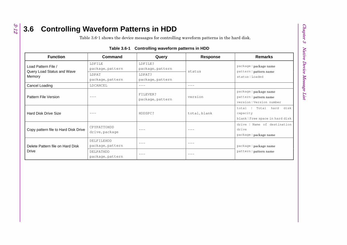
Chapter 3 N
ative Device M
essage List
3-12 3.6 Controlling Waveform Patterns in HDD Table 3.6-1 shows the device messages for controlling waveform patterns in the hard disk.
Table 3.6-1 Controlling waveform patterns in HDD
Function Command Query Response Remarks
LDFILE package,pattern
LDFILE? package,pattern Load Pattern File /
Query Load Status and Wave Memory LDPAT
package,pattern LDPAT? package,pattern
status
package : package name
pattern : pattern name
status : Loaded
Cancel Loading LDCANCEL --- ---
Pattern File Version --- FILEVER? package,pattern
version
package : package name
pattern : pattern name
version : Version number
Hard Disk Drive Size --- HDDSPC? total,blank total : Total hard disk
capacity
blank : Free space in hard disk
Copy pattern file to Hard Disk Drive CPYPATTOHDD drive,package
--- --- drive : Name of destination drive
package : package name
DELFILEHDD package,pattern
--- --- Delete Pattern file on Hard Disk Drive DELPATHDD
package,pattern --- ---
package : package name
pattern : pattern name

3.7 Modulation and AWGN Settings Device messages for setting modulation and AWGN are shown in Table 3.7-1.
Table 3.7-1 Modulation and AWGN setting messages
Function Command Query Response Remarks
Modulation MOD on_off MOD? on_off
Sampling Clock --- SAMPLINGCLK? freq
AWGN AWGN on_off AWGN? on_off
C/N Ratio PATWMPOWRATIO level PATWMPOWRATIO? level
Target of C/N Setting POWRATIOTARGET target
POWERRATIOTARGET? target target : target to change
= CARRIER | NOISE | CONSTANT
Carrier Power CARRIERPOW level CARRIERPOW? level
3-13
3.7 M
odulation and AW
GN
Settings
Native Device Message List 3Native Device Message List
3

Chapter 3 N
ative Device M
essage List
3-14 3.8 External Input Signal Settings Device messages for external input settings are shown in Table 3.8-1.
Table 3.8-1 External input signal setting messages
Function Command Query Response Remarks
External Trigger SFTRG on_off SFTRG? on_off
External Trigger Source STDLYSRC source STDLYSRC? source source : signal source
= EXTTRG | KEY | BUS
SFTRGMODE mode SFTRGMODE? mode mode : operating time = START | FRAME
External Trigger Mode
STGS mode STGS? mode mode : operating time
= INT | EXTSTA | EXTFRM
STDLYSYM delay STDLYSYM? delay delay : delay time
= (Number of symbols or chips)External Trigger Delay
--- STDLYTIME? time time : delay time (s)
External Trigger Edge EIST edge EIST? edge edge : polarity
= RISE | FALL
Baseband Reference Clock Source REFCLKSRC source REFCLKSRC? source INT source : clock source
= INT | EXT |
Baseband Reference Clock REFCLKVAL clock REFCLKVAL? clock clock : reference clock
= SIXTEENTH | EIGHTH | QUARTER | HALF | 1 | 2 | 4 | 8 | 16
Baseband Reference Clock Condition
--- BBREFCOND? status status : lock status
= NORMAL | CHKEXT
Pulse Modulation Source PMO source PMO? source source : signal source
= INT | EXT | OFF

3-15
3.7 M
odulation and AW
GN
Settings
Native Device Message List 3Native Device Message List 3
Table 3.8-1 External input signal setting messages (Cont’d)
Function Command Query Response Remarks
Frame Count FRAMECOUNT integer FRAMECOUNT? integer integer : Number of output
frames
Remote Command Trigger SFTGGENBUS --- ---

Chapter 3 N
ative Device M
essage List
3-16 3.9 External Output Signal Settings Device messages for external output settings are shown in Table 3.9-1.
Table 3.9-1 External output signal setting messages
Function Command Query Response Remarks
Marker Edit MARKEREDIT marker,mode MARKEREDIT? marker mode
marker : marker type
= 1 | 2 | 3
mode : marker mode = OFF | ON | PATSYNC
Marker Polarity MARKERPOL marker,polarity
MARKERPOL? marker polarity
marker : marker type = 1 | 2 | 3
polarity : polarity = POSITIVE | NEGATIVE
Marker Pulse Start Offset Value MARKEREDITOFFSET marker,offset
MARKEREDITOFFSET? marker
offset marker : marker type
= 1 | 2 | 3
offset : pulse start offset
Marker Pulse Width Value MARKEREDITWIDTH marker,width
MARKEREDITWIDTH? marker
width marker : marker type
= 1 | 2 | 3
width : pulse width
Marker Pulse Cycle Value MARKEREDITCYCLE marker,cycle
MARKEREDITCYCLE? marker
cycle marker : marker type = 1 | 2 | 3
cycle : pulse cycle

3-17
3.9 E
xternal Output Signal Settings
Native Device Message List 3Native Device Message List 3
3.10 Setting Trigger to Be Output to SG Marker of SA/SPA Tables 3.10-1 shows the device messages for setting the trigger to be output to the SG marker of SA/SPA.
Table 3.10-1 Setting trigger to be output to SG marker of SA/SPA
Function Command Query Response Remarks
SA Trigger Out SATRGOUT triggertoSA SATRGOUT? triggertoSA triggertoSA : trigger selection
= MARKER1 | MARKER2 | MARKER3 | PATSYNC

Chapter 3 N
ative Device M
essage List
3-18.
3.11 Display Settings Device messages for display settings are shown in Table 3.11-1.
Table 3.11-1 Display setting messages
Function Command Query Response Remarks
SG Window Position SGWINDOWPOS position SGWINDOWPOS? position position : display position
= TOP | BOTTOM
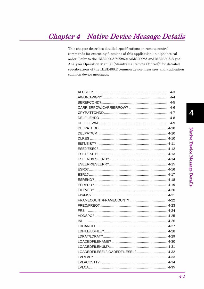
Chapter 4 Native Device Message Details
4-1
4
Native D
evice Message D
etails
This chapter describes detailed specifications on remote control commands for executing functions of this application, in alphabetical order. Refer to the “MS2690A/MS2691A/MS2692A and MS2830A Signal Analyzer Operation Manual (Mainframe Remote Control)” for detailed specifications of the IEEE488.2 common device messages and application common device messages.
ALCSTT? ............................................................................. 4-3 AWGN/AWGN?.................................................................... 4-4 BBREFCOND?..................................................................... 4-5 CARRIERPOW/CARRIERPOW? ........................................ 4-6 CPYPATTOHDD.................................................................. 4-7 DELFILEHDD....................................................................... 4-8 DELFILEWM ........................................................................ 4-9 DELPATHDD ....................................................................... 4-10 DELPATWM......................................................................... 4-10 DLRES ................................................................................. 4-10 EIST/EIST? .......................................................................... 4-11 ESE0/ESE0?........................................................................ 4-12 ESE1/ESE1?........................................................................ 4-13 ESEEND/ESEEND?............................................................. 4-14 ESEERR/ESEERR?............................................................. 4-15 ESR0?.................................................................................. 4-16 ESR1?.................................................................................. 4-17 ESREND? ............................................................................ 4-18 ESRERR? ............................................................................ 4-19 FILEVER? ............................................................................ 4-20 FIS/FIS? ............................................................................... 4-21 FRAMECOUNT/FRAMECOUNT? ..................................... 4-22
FREQ/FREQ? ...................................................................... 4-23 FRS ................................................................................... 4-24 HDDSPC? ............................................................................ 4-25 INI ................................................................................... 4-26 LDCANCEL.......................................................................... 4-27 LDFILE/LDFILE?.................................................................. 4-28 LDPAT/LDPAT?................................................................... 4-29 LOADEDFILENAME? .......................................................... 4-30 LOADEDFILENUM?............................................................. 4-31 LOADEDFILESEL/LOADEDFILESEL?................................ 4-32 LVL/LVL? ............................................................................. 4-33 LVLACCSTT? ...................................................................... 4-34 LVLCAL................................................................................ 4-35

Chapter 4 Native Device Message Details
4-2
LVLSTTLST? ....................................................................... 4-36 MARKEREDIT/MARKEREDIT?........................................... 4-37 MARKEREDITCYCLE/MARKEREDITCYCLE?................... 4-38 MARKEREDITOFFSET/MARKEREDITOFFSET? .............. 4-39 MARKEREDITWIDTH/MARKEREDITWIDTH? ................... 4-40 MARKERPOL/MARKERPOL?............................................. 4-41 MOD/MOD? ......................................................................... 4-42 OIS/OIS?.............................................................................. 4-43 OLS ................................................................................... 4-44 OLU/OLU? ........................................................................... 4-45 OLVL/OLVL?........................................................................ 4-46 OOF/OOF?........................................................................... 4-47 OOS/OOS? .......................................................................... 4-48 ORL/ORL? ........................................................................... 4-49 ORLR? ................................................................................. 4-50 ORLV/ORLV?....................................................................... 4-51 PAT ................................................................................... 4-52 PATNAME?.......................................................................... 4-52 PATNUM?............................................................................ 4-52 PATRUNSTT?...................................................................... 4-53 PATWMPOWRATIO/PATWMPOWRATIO?........................ 4-54 PMO/PMO?.......................................................................... 4-55 POWRATIOTARGET/POWRATIOTARGET? ..................... 4-56 PRE ................................................................................... 4-57 REFCLKSRC/REFCLKSRC? .............................................. 4-58 REFCLKVAL/REFCLKVAL? ................................................ 4-59 SAMPLINGCLK?.................................................................. 4-61 SATRGOUT/SATRGOUT? .................................................. 4-62 SFTGGENBUS .................................................................... 4-63
SFTRG/SFTRG?.................................................................. 4-63 SFTRGMODE/SFTRGMODE?............................................ 4-64 SGWINDOWPOS/SGWINDOWPOS?................................. 4-65 SPREV/SPREV?.................................................................. 4-66 STDLYSRC/STDLYSRC?.................................................... 4-67 STDLYSYM/STDLYSYM? ................................................... 4-68 STDLYTIME?....................................................................... 4-69 STGS/STGS?....................................................................... 4-70 SYS/SYS?............................................................................ 4-71 VDSPL/VDSPL?................................................................... 4-72 WMSPC? ............................................................................. 4-72

Chapter 4 Native Device Message Details
4-3
4
Native D
evice Message D
etails
ALCSTT? ALC Status Query
Function
This command queries the output level alarm information.
Query
ALCSTT?
Response
status
Parameter
status Level alarm status NORMAL Normal state ALCALARM ALC circuit is abnormal.
Example of Use
To query level alarm status. ALCSTT?

Chapter 4 Native Device Message Details
4-4
AWGN/AWGN? AWGN
Function
This command turns AWGN output ON/OFF.
Command
AWGN on_off
Query
AWGN?
Response
on_off
Parameter
on_off AWGN output On/Off ON On OFF Off
Details
Outputs a signal with AWGN added when AWGN is ON. The AWGN output function can be set to ON or OFF only when a waveform pattern file is selected and the modulation is enabled (ON).
The AWGN output function is automatically set to OFF when a waveform pattern is changed.
Example of Use
To add AWGN to output signal. AWGN ON

Chapter 4 Native Device Message Details
4-5
4
Native D
evice Message D
etails
BBREFCOND? Baseband Reference Clock Condition
Function
This command queries the lock status of the baseband reference clock.
Query
BBREFCOND?
Response
status
Parameter
status Lock status of reference clock NORMAL Normal CHKEXT Lock abnormal status when an external reference
signal source is used.
Example of Use
To query the lock status of the baseband reference clock. BBREFCOND?

Chapter 4 Native Device Message Details
4-6
CARRIERPOW/CARRIERPOW? Carrier Power
Function
This command sets the carrier signal level when AWGN is ON.
Command
CARRIERPOW level
Query
CARRIERPOW?
Response
level
Parameter
level Carrier signal level when AWGN is ON. Range Resolution 0.01 dB Suffix code DBM
Example of Use
To set the carrier signal level when AWGN is ON to –55.0 dBm. AWGN ON
CARRIERPOW -55.0DBM
Related Command
AWGN AWGN On/Off setting

Chapter 4 Native Device Message Details
4-7
4
Native D
evice Message D
etails
CPYPATTOHDD Copy pattern file to Hard Disk Drive
Function
This command copies the waveform pattern file from the specified drive to the internal hard disk drive. Specify a waveform pattern by using a package name. The package name is the name of the folder that stores the waveform pattern file.
Command
CPYPATTOHDD drive,package
Parameter
drive Copy source drive name (D to Z, D when omitted) package Package name to copy (Character string) Or, ROOT
Details
An error occurs when the specified drive or waveform pattern file cannot be found.
When the package name (package) is omitted, all the packages in the root folder of the specified drive will be copied.
When ROOT is specified for <package>, all the patterns in the root folder of the specified drive will be copied.
Example of Use
To copy the waveform pattern in the package "WCDMA" of Drive D to the internal hard disk. CPYPATTOHDD D,”WCDMA”

Chapter 4 Native Device Message Details
4-8
DELFILEHDD Delete Pattern file on Hard Disk Drive
Function
This command deletes the waveform pattern file on the hard disk.
Command
DELFILEHDD package,pattern
Parameter
package Package name (Character string) pattern Pattern name (Character string)
Details
This command does not delete waveform patterns in the waveform memory.
Example of Use
To delete the "TEST" pattern in the package "WCDMA". DELFILEHDD "WCDMA","TEST"
Related Command
DELPATHDD Same as DELFILEHDD

Chapter 4 Native Device Message Details
4-9
4
Native D
evice Message D
etails
DELFILEWM Delete Pattern file on Waveform Memory
Function
This command deletes the waveform pattern file in the waveform memory.
Command
DELFILEWM package,pattern
DELFILEWM ALL
Parameter
package Package name (Character string) ALL Deleting All Waveform Patterns pattern Pattern name (Character string)
Details
This command does not delete waveform patterns on the hard disk.
Example of Use
To delete the "TEST" pattern in the package "WCDMA". DELFILEWM "WCDMA","TEST"
Related Command
DELPATWM Same as DELFILEWM

Chapter 4 Native Device Message Details
4-10
DELPATHDD Delete Pattern file on Hard Disk Drive
Function
This command deletes the waveform pattern file on the hard disk.
Same as DELFILEHDDRefer to section explaining DELFILEHDD.
DELPATWM Delete Pattern file on Waveform Memory
Function
This command deletes the waveform pattern file in the waveform memory.
Same as DELFILEWM. Refer to section explaining DELFILEWM.
DLRES Waveform Restart
Function
This command plays waveform pattern from the beginning.
Command
DLRES
Example of Use
To play waveform pattern from the beginning. DLRES

Chapter 4 Native Device Message Details
4-11
4
Native D
evice Message D
etails
EIST/EIST? External Trigger Edge
Function
This command sets the polarity of the external trigger input.
Command
EIST edge
Query
EIST?
Response
edge
Parameter
edge External trigger polarity RISE Rise FALL Fall
Example of Use
To set the external trigger polarity to Fall. EIST FALL
Related Command
SFTRG External trigger On/Off setting.

Chapter 4 Native Device Message Details
4-12
ESE0/ESE0? Extended End Event Status Enable Register
Function
This command sets the extended end event status enable register. When an end event occurs in the specified application, the end summary bit (ESB) value of the corresponding status byte register is set to 1 (true).
Command
ESE0 n
Query
ESE0?
Response
n
Parameter
n Extended end event status enable register Value = bit0 + bit1 + ... + bit7
bit7 = 27 = 128 Bit 7: Not used bit6 = 26 = 64 Bit 6: Not used bit5 = 25 = 32 Bit 5: Not used bit4 = 24 = 16 Bit 4: Not used bit3 = 23 = 8 Bit 3: Not used bit2 = 22 = 4 Bit 2: Not used bit1 = 21 = 2 Bit 1: Not used bit0 = 20 = 1 Bit 0: Signal Generator Function
Details
Set the sum of the values for bits to be enabled to the parameter, from the values 20 = 1, 21 = 2, 22 = 4, 23 = 8, 24 = 16, 25 = 32, 26 = 64, and 27 = 128, corresponding to the extended end event status enable register bits 0, 1, 2, 3, 4, 5, 6, and 7.
Example of Use
To enable an end event for the Signal Generator function. ESE0 1
Related Command
ESR0? Extended end event status register query.
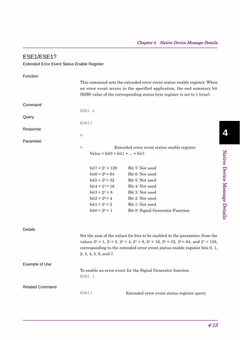
Chapter 4 Native Device Message Details
4-13
4
Native D
evice Message D
etails
ESE1/ESE1? Extended Error Event Status Enable Register
Function
This command sets the extended error event status enable register. When an error event occurs in the specified application, the end summary bit (ESB) value of the corresponding status byte register is set to 1 (true).
Command
ESE1 n
Query
ESE1?
Response
n
Parameter
n Extended error event status enable register Value = bit0 + bit1 + ... + bit7
bit7 = 27 = 128 Bit 7: Not used bit6 = 26 = 64 Bit 6: Not used bit5 = 25 = 32 Bit 5: Not used bit4 = 24 = 16 Bit 4: Not used bit3 = 23 = 8 Bit 3: Not used bit2 = 22 = 4 Bit 2: Not used bit1 = 21 = 2 Bit 1: Not used bit0 = 20 = 1 Bit 0: Signal Generator Function
Details
Set the sum of the values for bits to be enabled to the parameter, from the values 20 = 1, 21 = 2, 22 = 4, 23 = 8, 24 = 16, 25 = 32, 26 = 64, and 27 = 128, corresponding to the extended error event status enable register bits 0, 1, 2, 3, 4, 5, 6, and 7.
Example of Use
To enable an error event for the Signal Generator function. ESE1 1
Related Command
ESR1? Extended error event status register query.

Chapter 4 Native Device Message Details
4-14
ESEEND/ESEEND? End Event Status Enable Register
Function
This command sets the end event status enable register that can be used for the Signal Generator function. When a specified end event occurs, the end summary bit (ESB) value corresponding to the event is set to 1 (true).
Command
ESEEND n
Query
ESEEND?
Response
n
Parameter
n End event status enable register Value = bit0 + bit1 + ... + bit7
Signal Generator function bit7 = 27 = 128 Bit 7: Not used bit6 = 26 = 64 Bit 6: Not used bit5 = 25 = 32 Bit 5: Completion of waveform pattern copy bit4 = 24 = 16 Bit 4: Completion of waveform pattern loading
to waveform memory bit3 = 23 = 8 Bit 3: Not used bit2 = 22 = 4 Bit 2: Not used bit1 = 21 = 2 Bit 1: Not used bit0 = 20 = 1 Bit 0: Not used
Details
Set the sum of the values for bits to be enabled to the parameter, from the values 20 = 1, 21 = 2, 22 = 4, 23 = 8, 24 = 16, 25 = 32, 26 = 64, and 27 = 128, corresponding to the end event status enable register bits 0, 1, 2, 3, 4, 5, 6, and 7.
Example of Use
To enable the waveform pattern loading completion event. SYS SG
ESEEND 16
Related Command
ESREND? End event status register query.

Chapter 4 Native Device Message Details
4-15
4
Native D
evice Message D
etails
ESEERR/ESEERR? Error Event Status Enable Register
Function
This command sets the error event status enable register that can be used for the Signal Generator function. When a specified error event occurs, the error summary bit (ESB) value corresponding to the event is set to 1 (true).
This command can be used for the currently active function.
Command
ESEERR n
Query
ESEERR?
Response
n
Parameter
n Error event status enable register Value = bit0 + bit1 + ... + bit7
Signal Generator function bit7 = 27 = 128 Bit 7: Not used bit6 = 26 = 64 Bit 6: Not used bit5 = 25 = 32 Bit 5: Waveform pattern copy error bit4 = 24 = 16 Bit 4: Waveform pattern loading to waveform
memory error bit3 = 23 = 8 Bit 3: Not used bit2 = 22 = 4 Bit 2: Not used bit1 = 21 = 2 Bit 1: Not used bit0 = 20 = 1 Bit 0: Not used
Details
Set the sum of the values for bits to be enabled to the parameter, from the values 20 = 1, 21 = 2, 22 = 4, 23 = 8, 24 = 16, 25 = 32, 26 = 64, and 27 = 128, corresponding to the error event status enable register bits 0, 1, 2, 3, 4, 5, 6, and 7.
Example of Use
To enable the waveform pattern loading error event. SYS SG
ESEEND 16
Related Command
ESEERR? Error event status register query.

Chapter 4 Native Device Message Details
4-16
ESR0? Extended End Event Status Register Query
Function
This command queries the extended end event status.
Query
ESR0?
Response
n
Parameter
n Extended End Event Status register Value = bit0 + bit1 + ... + bit7
bit7 = 27 = 128 Bit 7: Not used bit6 = 26 = 64 Bit 6: Not used bit5 = 25 = 32 Bit 5: Not used bit4 = 24 = 16 Bit 4: Not used bit3 = 23 = 8 Bit 3: Not used bit2 = 22 = 4 Bit 2: Not used bit1 = 21 = 2 Bit 1: Not used bit0 = 20 = 1 Bit 0: Signal Generator Function
Details
The response is the sum of the values 20 = 1, 21 = 2, 22 = 4, 23 = 8, 24 = 16, 25 = 32, 26 = 64, and 27 = 128, corresponding to the extended end event status register bits 0, 1, 2, 3, 4, 5, 6, and 7. When a response is read, the extended end event status register value is cleared.
Example of Use
To query the extended end event status register. ESR0?
Related Command
ESE0 Extended END event status enable register contents

Chapter 4 Native Device Message Details
4-17
4
Native D
evice Message D
etails
ESR1? Extended Error Event Status Register Query
Function
This command queries the extended error event status.
Query
ESR1?
Response
n
Parameter
n Extended Error Event Status register Value = bit0 + bit1 + ... + bit7
bit7 = 27 = 128 Bit 7: Not used bit6 = 26 = 64 Bit 6: Not used bit5 = 25 = 32 Bit 5: Not used bit4 = 24 = 16 Bit 4: Not used bit3 = 23 = 8 Bit 3: Not used bit2 = 22 = 4 Bit 2: Not used bit1 = 21 = 2 Bit 1: Not used bit0 = 20 = 1 Bit 0: Signal Generator Function
Details
The response is the sum of the values 20 = 1, 21 = 2, 22 = 4, 23 = 8, 24 = 16, 25 = 32, 26 = 64, and 27 = 128, corresponding to the extended error event status register bits 0, 1, 2, 3, 4, 5, 6, and 7. When a response is read, the extended error event status register value is cleared.
Example of Use
To query the extended error event status register. ESR1?
Related Command
ESE1 Extended ERROR event status enable register contents

Chapter 4 Native Device Message Details
4-18
ESREND? Event Status Register Query
Function
This command queries the end event status that is used for the Signal Generator.
Query
ESREND?
Response
n
Parameter
n End Event Status register Value = bit0 + bit1 + ... + bit7
Signal Generator function bit7 = 27 = 128 Bit 7: Not used bit6 = 26 = 64 Bit 6: Not used bit5 = 25 = 32 Bit 5: Completion of waveform pattern copy bit4 = 24 = 16 Bit 4: Completion of waveform pattern loading
to waveform memory bit3 = 23 = 8 Bit 3: Not used bit2 = 22 = 4 Bit 2: Not used bit1 = 21 = 2 Bit 1: Not used bit0 = 20 = 1 Bit 0: Not used
Details
The response is the sum of the values 20 = 1, 21 = 2, 22 = 4, 23 = 8, 24 = 16, 25 = 32, 26 = 64, and 27 = 128, corresponding to the error event status register bits 0, 1, 2, 3, 4, 5, 6, and 7. When a response is read, the end event status register value is cleared.
Example of Use
To query the end event status register for the Signal Generator function. SYS SG ESREND?
Related Command
ESEERR End event status enable register setting

Chapter 4 Native Device Message Details
4-19
4
Native D
evice Message D
etails
ESRERR? Error Event Status Register Query
Function
This command queries the error event status that is used for the Signal Generator function.
This command can be used for the currently active function.
Query
ESRERR?
Response
n
Parameter
n Error event status register Value = bit0 + bit1 + ... + bit7
Signal Generator function bit7 = 27 = 128 Bit 7: Not used bit6 = 26 = 64 Bit 6: Not used bit5 = 25 = 32 Bit 5: Waveform pattern copy error bit4 = 24 = 16 Bit 4: Waveform pattern loading to waveform
memory error bit3 = 23 = 8 Bit 3: Not used bit2 = 22 = 4 Bit 2: Not used bit1 = 21 = 2 Bit 1: Not used bit0 = 20 = 1 Bit 0: Not used
Details
The response is the sum of the values 20 = 1, 21 = 2, 22 = 4, 23 = 8, 24 = 16, 25 = 32, 26 = 64, and 27 = 128, corresponding to the error event status register bits 0, 1, 2, 3, 4, 5, 6, and 7. When a response is read, the error event status register value is cleared.
Example of Use
To query the error event status register for the Signal Generator function. SYS SG
ESRERR?
Related Command
ESEERR Error event status enable register setting

Chapter 4 Native Device Message Details
4-20
FILEVER? File Version Query
Function
This command queries the waveform pattern file version on the hard disk.
Query
FILEVER? package,pattern
Response
version
Parameter
package Package name (Character string) pattern Pattern name (Character string) version Version number
Example of Use
To query the "TEST" pattern version number of the package "WCDMA". FILEVER? "WCDMA","TEST"

Chapter 4 Native Device Message Details
4-21
4
Native D
evice Message D
etails
FIS/FIS? Frequency - Step Value
Function
This command sets the fluctuation width (step value) when the frequency is increased/decreased in step.
Command
FIS freq
Query
FIS?
Response
freq
Parameter
freq Frequency step width
Range 0.01 Hz to 1 GHz Resolution 0.01 Hz Default 100 kHz Response unit Hz Suffix code HZ, KHZ, KZ, MHZ, MZ, GHZ, GZ
Example of Use
To set the frequency step width to 200 kHz FIS 200KHZ
Related Command
FRS Setting frequency by stepping up and down

Chapter 4 Native Device Message Details
4-22
FRAMECOUNT/FRAMECOUNT? Frame Count
Function
This command sets the Frame Count from the Signal Generator option.
Command
FRAMECOUNT integer
Query
FRAMECOUNT?
Response
integer
Parameter
integer Specifying the output frame count Range 1 to 32767 Resolution 1 Default 1
Example of Use
To set the output frame count to 10. FRAMECOUNT 10
To query the Frame Count from the Signal Generator option. FRAMECOUNT?
> 10

Chapter 4 Native Device Message Details
4-23
4
Native D
evice Message D
etails
FREQ/FREQ? Frequency
Function
This command sets frequency
Command
FREQ freq
Query
FREQ?
Response
freq
Parameter
freq Frequency
Range 250 MHz to 3.6 GHz (*) 250 MHz to 6 GHz (**)
Resolution 0.01 Hz Default 1 GHz Response unit Hz Suffix code HZ, KHZ, KZ, MHZ, MZ, GHZ, GZ When omitted: Hz
(*) When option 020/120 is installed. (**) When option 021/121 is installed.
Example of Use
To set the frequency to 800 MHz FREQ 800MHZ

Chapter 4 Native Device Message Details
4-24
FRS Frequency Step Up/Down
Function
This command raises/lowers the frequency in a set width (step value).
Command
FRS up_down
Parameter
up_down Fluctuation direction of the frequency step width UP Raises the frequency DN Lowers the frequency DOWN Lowers the frequency
Example of Use
To raise the frequency twice in the 200 kHz width. FIS 200KHZ
FRS UP
FRS UP
Related Command
FIS Sets the frequency step width.

Chapter 4 Native Device Message Details
4-25
4
Native D
evice Message D
etails
HDDSPC? Hard Disk Drive Size Query
Function
This command queries hard disk free space information.
Query
HDDSPC?
Response
total,blank
Parameter
total Total hard disk size
Response unit Byte
blank Hard disk free space Response unit Byte
Example of Use
To query the hard disk size. HDDSPC?

Chapter 4 Native Device Message Details
4-26
INI Preset
Function
This command executes initialization.
Command
INI
Details
The application currently selected is the target.
Example of Use
To execute initialization INI
Related Command
PRE Same function as INI. *RST Initialization of all applications

Chapter 4 Native Device Message Details
4-27
4
Native D
evice Message D
etails
LDCANCEL Cancel Loading
Function
This command cancels loading waveform patterns to waveform memory.
Command
LDCANCEL
Example of Use
To cancel loading waveform patterns to waveform memory. LDCANCEL

Chapter 4 Native Device Message Details
4-28
LDFILE/LDFILE? Load Pattern File/Check Status of Lading Pattern and Waveform Memory
Function
This command starts loading the waveform pattern from the hard disk to the waveform memory. Load results and current status for the specified waveform pattern are returned in response to the query.
Command
LDFILE package,pattern
Query
LDFILE? package,pattern
Response
status
Parameter
package Package name (Character string) pattern Pattern name (Character string) status Status
EXIST Already loaded ENABLE Can be loaded NEED_LICENSE License required NO_PATTERN_HDD No corresponding file TOO_LARGE_SIZE Insufficient waveform memory free
space DISABLE_LOAD Internal error INVALID_VERSION Version mismatch FILE_ERROR Pattern file analysis error WVI_FILE_ERROR Illegal pattern file (.wvi) PATTERN_OVER_ON_WM Exceeded number of loadable waveform
pattern files PACKAGE_OVER_ON_WM Exceeded number of loadable packages PATTERN_OVER_ON_PACKAGE
Exceeded number of loadable waveform pattern files in 1 package
Details
If a waveform pattern is loaded when the same waveform pattern has already been loaded, the existing waveform pattern is overwritten.
Example of Use
To start loading "TEST" pattern in package "WCDMA". LDFILE "WCDMA","TEST"
*OPC? // Loaded when 1 is returned

Chapter 4 Native Device Message Details
4-29
4
Native D
evice Message D
etails
Related Command
LDPAT Same as LDFILE
LDPAT/LDPAT? Load Pattern File/Check Status of Lading Pattern and Waveform Memory
Function
This command starts loading the waveform pattern from the hard disk to the waveform memory. Load results and current status for the specified waveform pattern are returned in response to the query.
Same function as LDFILE. Refer to the descriptions of LDFILE for details.

Chapter 4 Native Device Message Details
4-30
LOADEDFILENAME? Loaded File Name in Waveform Memory
Function
This command queries the waveform pattern filename loaded in the waveform memory.
Query
LOADEDFILENAME? n
Response
package,pattern
Parameter
n Random numbers allocated to waveform patterns. Range 0 to (Number of waveform patterns in the waveform
memory - 1) Resolution 1 package Package name (Character string) pattern Pattern name (Character string)
Example of Use
To query the waveform pattern filename loaded in the waveform memory. LOADEDFILENUM? Response > 3 LOADEDFILENAME? 0
LOADEDFILENAME? 1
LOADEDFILENAME? 2
Related Command
LOADEDFILENUM? Querying the number of waveform pattern files in the waveform memory.

Chapter 4 Native Device Message Details
4-31
4
Native D
evice Message D
etails
LOADEDFILENUM? Number of Loaded Files Query
Function
This command queries the number of waveform pattern files loaded in the waveform memory.
Query
LOADEDFILENUM?
Response
n
Parameter
n Number of waveform pattern files loaded to waveform memory
Range 0 to 1000 Resolution 1
Example of Use
To query the number of waveform pattern files loaded in the waveform memory. LOADEDFILENUM?
> 3
Related Command
PATNUM? Same as LOADEDFILENUM?

Chapter 4 Native Device Message Details
4-32
LOADEDFILESEL/LOADEDFILESEL? Select Waveform File
Function
This selects the waveform pattern file to be played from the waveform pattern files loaded to the waveform memory.
Command
LOADEDFILESEL package,pattern
Query
LOADEDFILESEL?
Response
package,pattern
Parameter
package Package name (Character string) NONE Waveform pattern file not selected
pattern Pattern name (Character string) NONE Waveform pattern file not selected
Example of Use
To select loading "TEST" pattern in package "WCDMA". LOADEDFILESEL "WCDMA","TEST"
Related Command
PAT Same as LOADEDFILESEL

Chapter 4 Native Device Message Details
4-33
4
Native D
evice Message D
etails
LVL/LVL? RF Output - On/Off
Function
This command turns RF output ON/OFF.
Command
LVL on_off
Query
LVL?
Response
on_off
Parameter
on_off RF Output ON On OFF Off
Example of Use
To set the RF signal output to Off. LVL OFF

Chapter 4 Native Device Message Details
4-34
LVLACCSTT? Level Accuracy Status Query
Function
This command queries the output level accuracy status.
Query
LVLACCSTT?
Response
status
Parameter
status Output level accuracy status NORMAL Normal state UNLEVELED Outside performance assurance status
Example of Use
To query the output level accuracy status. LVLACCSTT?

Chapter 4 Native Device Message Details
4-35
4
Native D
evice Message D
etails
LVLCAL SG Level Calibration
Function
This command calibrates the output level.
Command
LVLCAL
Example of Use
To calibrate the output level. LVLCAL

Chapter 4 Native Device Message Details
4-36
LVLSTTLST? Level Status List Query
Function
This command queries the output level status.
Query
LVLSTTLST?
Response
unit,offset,unleveled, INTALC,CONTOFF,
relative,NORMAL
Parameter
unit Voltage display unit EMF Open circuit voltage TERM Termination voltage
offset Level offset OFFSETON On OFFSETOFF Off
unleveled Output level accuracy status NORMAL Normal state UNLEVELED Outside level accuracy assurance
INTALC Fixed Value
CONTOFF Fixed Value
relative Relative output mode RELON On RELOFF Off
NORMAL Fixed Value
Example of Use
To query the output level status. LVLSTTLST?

Chapter 4 Native Device Message Details
4-37
4
Native D
evice Message D
etails
MARKEREDIT/MARKEREDIT? Marker Edit
Function
This command specifies the user setting mode for the external output marker.
Command
MARKEREDIT n,mode
Query
MARKEREDIT? n
Response
mode
Parameter
n Marker type 1 Marker 1 2 Marker 2 3 Marker 3 mode User setting mode OFF Outputs the marker previously recorded in the
waveform pattern. ON Outputs the user setting marker. PATSYNC Outputs the marker at the start of the waveform
pattern.
Details
OFF can only be specified if a waveform pattern that consists of 14-bit resolution IQ data is selected. If a 15-bit or 16-bit resolution waveform pattern is selected, the following restrictions apply:
15-bit resolution: Markers 2 and 3 cannot be set to OFF. 16-bit resolution: Markers 1 to 3 cannot be set to OFF.
Example of Use
To specify the user setting mode for marker 1. MARKEREDIT 1,ON

Chapter 4 Native Device Message Details
4-38
MARKEREDITCYCLE/MARKEREDITCYCLE? Marker Edit Mode Cycle Value
Function
This command sets the output pulse cycle when the external output marker is set to the user setting marker.
Command
MARKEREDITCYCLE n,cycle
Query
MARKEREDITCYCLE? n
Response
cycle
Parameter
n Marker type 1 Marker 1 2 Marker 2 3 Marker 3 cycle Output pulse cycle
Example of Use
To set Marker 1 to the user setting marker and set the output pulse cycle to 200. 1 : MARKEREDIT 1,ON
2 : MARKEREDITCYCLE 1,200
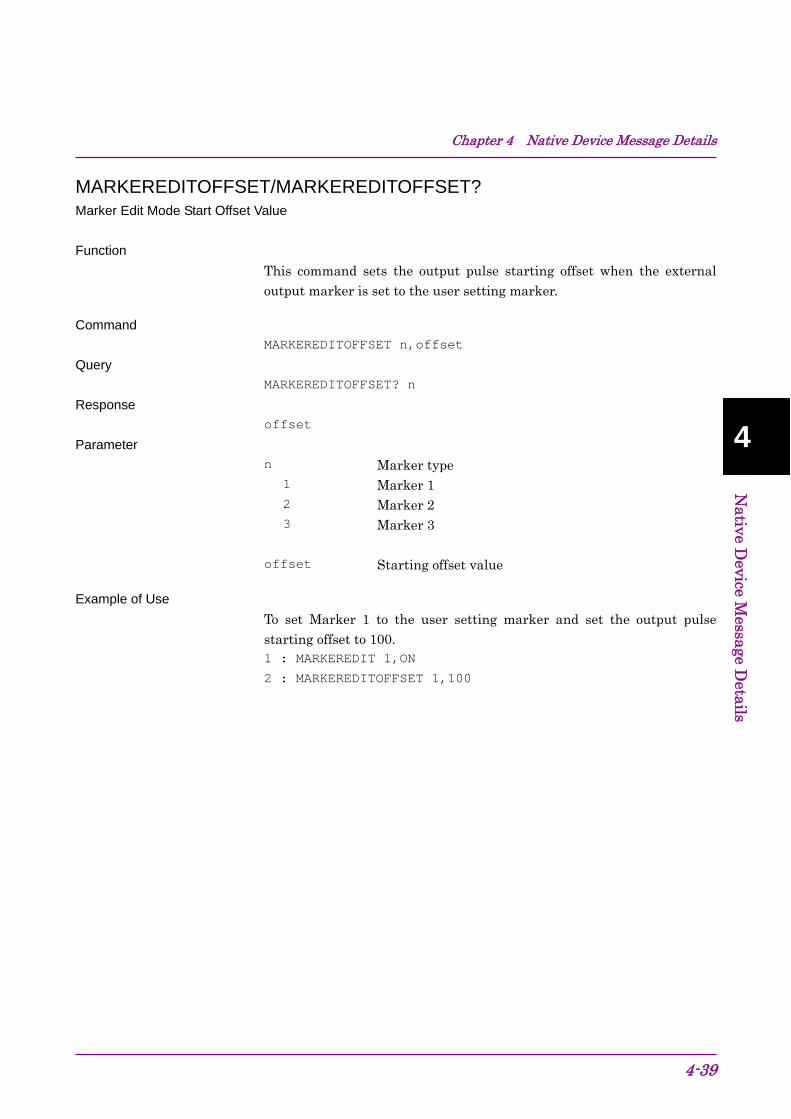
Chapter 4 Native Device Message Details
4-39
4
Native D
evice Message D
etails
MARKEREDITOFFSET/MARKEREDITOFFSET? Marker Edit Mode Start Offset Value
Function
This command sets the output pulse starting offset when the external output marker is set to the user setting marker.
Command
MARKEREDITOFFSET n,offset
Query
MARKEREDITOFFSET? n
Response
offset
Parameter
n Marker type 1 Marker 1 2 Marker 2 3 Marker 3
offset Starting offset value
Example of Use
To set Marker 1 to the user setting marker and set the output pulse starting offset to 100. 1 : MARKEREDIT 1,ON
2 : MARKEREDITOFFSET 1,100

Chapter 4 Native Device Message Details
4-40
MARKEREDITWIDTH/MARKEREDITWIDTH? Marker Edit Mode Width Value
Function
This command sets the output pulse width when the external output marker is set to the user setting marker.
Command
MARKEREDITWIDTH n,width
Query
MARKEREDITWIDTH? n
Response
width
Parameter
n Marker type 1 Marker 1 2 Marker 2 3 Marker 3
width Pulse width
Example of Use
To set Marker 1 to the user setting marker and set the output pulse width to 50. 1 : MARKEREDIT 1,ON
2 : MARKEREDITWIDTH 1,50

Chapter 4 Native Device Message Details
4-41
4
Native D
evice Message D
etails
MARKERPOL/MARKERPOL? Marker Polarity
Function
This command sets the polarity of the external output marker signal.
Command
MARKERPOL n,polarity
Query
MARKERPOL? n
Response
polarity
Parameter
n Marker type 1 Marker 1 2 Marker 2 3 Marker 3 polarity Polarity POS Positive (Positive polarity) NEG Negative (Negative polarity)
Example of Use
To set the polarity of Marker 1 to negative. MARKERPOL 1,NEG
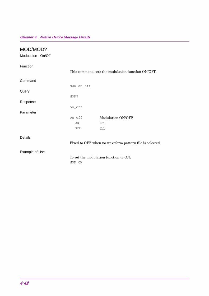
Chapter 4 Native Device Message Details
4-42
MOD/MOD? Modulation - On/Off
Function
This command sets the modulation function ON/OFF.
Command
MOD on_off
Query
MOD?
Response
on_off
Parameter
on_off Modulation ON/OFF ON On OFF Off
Details
Fixed to OFF when no waveform pattern file is selected.
Example of Use
To set the modulation function to ON. MOD ON

Chapter 4 Native Device Message Details
4-43
4
Native D
evice Message D
etails
OIS/OIS? Output Level - Set Value
Function
This command sets the numerical value fluctuation width (step value) when the output level is increased/decreased in step units.
Command
OIS level
Query
OIS?
Response
level
Parameter
level Step width of the output level Range 0.01 to 100.00 dB Resolution 0.01 dB Default Response unit dB Suffix code DB
Example of Use
To set the output level step width to 5.00 dB. OIS 5.00DB
Related Command
OLS Setting output level by stepping up and down

Chapter 4 Native Device Message Details
4-44
OLS Level Set Up/Down
Function
This command increments or decrements the output level by a specified amount.
Command
OLS up_down
Parameter
up_down Incrementing or decrementing the output level in step units
UP Raises the output level DN Lowers the output level DOWN Lowers the output level
Example of Use
To raise the output level twice using 2.00 dB width. OIS 2.00DB
OLS UP
OLS UP
Related Command
OIS Sets the output level in step units.

Chapter 4 Native Device Message Details
4-45
4
Native D
evice Message D
etails
OLU/OLU? Level Unit
Function
This command sets the output level unit.
Command
OLU unit
Query
OLU?
Response
unit
Parameter
unit Output level unit DBM dBm DBU dBV
Example of Use
To set the level setting unit to dBm. OLU DBM

Chapter 4 Native Device Message Details
4-46
OLVL/OLVL? Output Level
Function
This command sets the output level. Command
OLVL level
Query
OLVL? unit
Response
level
Parameter
level Output Level
Range -40.00 dBm to +20.00 dBm (>25 MHz)(*) -40.00 dBm to +2.00 dBm (≤25 MHz)(*) -136.00 dBm to +15.00 dBm (>25 MHz)(**) -136.00 dBm to -3.00 dBm (≤25 MHz)(**) Resolution 0.01 dB Default -40.00 dBm (*) -136.00 dBm (**) Suffix code DBM,DBU When omitted: DBM
(*) When option 022/122 is not installed. (**) When option 022/122 is installed.
unit Output level unit (optional) DBM dBm DBU dBV When omitted: dBm
Details
The range is based on an output level unit of dBm.
The range differs as follows according to the conditions:
When dBV (Term) is set as the output level unit
Range + 106.99 dB
When dBV (EMF) is set as the output level unit
Range + 113.01 dB
When Offset is on: Range + Offset Value

Chapter 4 Native Device Message Details
4-47
4
Native D
evice Message D
etails
Example of Use
Setting the output level to –30.00 dBm OLVL -30.00DBM
OOF/OOF? Level Offset - On/Off
Function
This command sets the output level offset ON/OFF. Command
OOF on_off
Query
OOF?
Response
on_off
Parameter
on_off Output level offset ON On OFF Off
Example of Use
To enable the output level offset. OOF ON

Chapter 4 Native Device Message Details
4-48
OOS/OOS? Level Offset - Level
Function
This command sets the output level offset value Command
OOS level
Query
OOS?
Response
level
Parameter
level Output level offset
Range -100.00 to 100.00 dB Resolution 0.01 dB Default 0.00 dB Response unit dB Suffix code DB
Example of Use
To set the output level offset to –15.00 dB. OOS -15.00DB

Chapter 4 Native Device Message Details
4-49
4
Native D
evice Message D
etails
ORL/ORL? Relative - On/Off
Function
This command sets the relative output level display ON/OFF. Command
ORL on_off
Query
ORL?
Response
on_off
Parameter
on_off Relative output level ON On OFF Off
Example of Use
To enable relative output level display. ORL ON

Chapter 4 Native Device Message Details
4-50
ORLR? Relative Level - Reference Level
Function
This command queries the reference output level at relative output level display mode (Output level when the relative display mode is set to ON).
Query
ORLR?
Response
level
Parameter
level Reference level of relative output
Range -40.00 dBm to +20.00 dBm (>25 MHz) (*) -40.00 dBm to +2.00 dBm (≤25 MHz) (*) -136.00 dBm to +15.00 dBm (>25 MHz) (**) -136.00 dBm to -3.00 dBm (≤25 MHz) (**) Resolution 0.01 dB Response unit dBm (*) When option 022/122 is not installed. (**) When option 022/122 is installed.
Details
The range is based on an output level unit of dBm.
The range differs as follows according to the conditions:
When dBV (Term) is set as the output level unit
Range + 106.99 dB
When dBV (EMF) is set as the output level unit
Range + 113.01 dB
When Offset is on: Range + Offset Value
Example of Use
To query reference level of relative output OLVL -75.00DBM
ORL ON
ORLR? Response> -75.00

Chapter 4 Native Device Message Details
4-51
4
Native D
evice Message D
etails
ORLV/ORLV? Relative Level
Function
This command sets the screen display output level at relative output level display mode.
Command
ORLV level
Query
ORLV?
Response
level
Parameter
level Relative output level
Range 60 dB width within the range of –60.00 dB to +60.00 dB (> 25 MHz)(*)
42 dB width within the range of –42.00 dB to +42.00 dB (≤ 25 MHz)(*)
151 dB width within the range of –151.00 dB to +151.00 dB (> 25 MHz)(**)
133 dB width within the range of –133.00 dB to +133.00 dB (≤ 25 MHz)(**)
Resolution 0.01 dB Response unit dB (*) When option 022/122 is not installed. (**) When option 022/122 is installed.
Details
The range differs as follows according to the conditions:
When Offset is on: Range + Offset Value
Example of Use
To set the relative output to +10.00 dB based on an output level of −75.00 dBm. OLVL -75.00DBM
ORL ON
ORLV 10.00DB

Chapter 4 Native Device Message Details
4-52
PAT Select Waveform File
Function
This selects the waveform pattern file to be played from the waveform pattern files loaded to the waveform memory.
The function is the same as that of LOADEDFILESEL. Refer to the descriptions of LOADEDFILESEL for details.
PATNAME? Loaded File Name in Waveform Memory
Function
This command queries the waveform pattern filename loaded in the waveform memory.
The function is the same as that of LOADEDFILENAME? Refer to the descriptions of LOADEDFILENAME? for details.
PATNUM? Number of Loaded Files
Function
This command queries the number of waveform pattern filenames loaded in the waveform memory.
The function is the same as that of LOADEDFILENUM? Refer to the descriptions of LOADEDFILENUM? for details.

Chapter 4 Native Device Message Details
4-53
4
Native D
evice Message D
etails
PATRUNSTT? Pattern Running Status Query
Function
This command queries the running status of a waveform pattern.
Query
PATRUNSTT?
Response
status
Parameter
status The waveform pattern running status
STOP Stopped PLAY Running
Example of Use
To query the waveform pattern status. PATRUNSTT?

Chapter 4 Native Device Message Details
4-54
PATWMPOWRATIO/PATWMPOWRATIO? Power Ratio
Function
This command sets the output ratio of AWGN to carrier (C/N) when AWGN is ON.
Command
PATWMPOWRATIO level
Query
PATWMPOWRATIO?
Response
level
Parameter
level C/N
Range -40 to +40 dB Resolution 0.01 Default -40.00 Response unit dB Suffix code DB
Details
The setting range may be narrowed if the RF output level is close to the upper or lower limit.
Example of Use
To set the C/N to 3 dB. PATWMPOWRATIO 3DB

Chapter 4 Native Device Message Details
4-55
4
Native D
evice Message D
etails
PMO/PMO? Pulse Modulation Source
Function
This command sets the pulse modulation signal source.
Command
PMO source
Query
PMO?
Response
source
Parameter
source Pulse modulation signal source.
INT Internal signal EXT External input signal OFF No pulse modulation
Example of Use
To set the pulse modulation signal source to internal signal. PMO INT

Chapter 4 Native Device Message Details
4-56
POWRATIOTARGET/POWRATIOTARGET? Target of C/N Setting
Function
This command sets the parameters to be changed when C/N is set.
Command
POWRATIOTARGET target
Query
POWRATIOTARGET?
Response
target
Parameter
target Parameter to be changed when C/N is set.
CARRIER Carrier signal NOISE AWGN CONSTANT Fixed output level (Carrier + AWGN)
Example of Use
To set AWGN as the parameter to be changed when C/N is set. POWRATIOTARGET NOISE

Chapter 4 Native Device Message Details
4-57
4
Native D
evice Message D
etails
PRE Preset
Function
This command executes initialization.
Command
PRE
Details
The application currently selected is the target.
Example of Use
To execute initialization PRE
Related Command
INI Same as PRE *RST Initializes all applications

Chapter 4 Native Device Message Details
4-58
REFCLKSRC/REFCLKSRC? Baseband Reference Clock Source
Function
This command sets baseband signal reference clock.
Command
REFCLKSRC source
Query
REFCLKSRC?
Response
source
Parameter
source Baseband signal reference clock
INT Internal signal (Default) EXT External input signal
Example of Use
To set the baseband signal reference clock to external input signal. REFCLKSRC EXT

Chapter 4 Native Device Message Details
4-59
4
Native D
evice Message D
etails
REFCLKVAL/REFCLKVAL? Baseband Reference Clock
Function
This command sets the baseband signal reference clock frequency in magnification ratio based on the sampling clock.
Command
REFCLKVAL clock
Query
REFCLKVAL?
Response
clock
Parameter
clock Baseband signal reference clock
SIXTEENTH Sampling Clock × 1/16 EIGHTH Sampling Clock × 1/8 QUARTER Sampling Clock × 1/4 HALF Sampling Clock × 1/2 1 Sampling Clock × 1 2 Sampling Clock × 2 4 Sampling Clock × 4 8 Sampling Clock × 8 16 Sampling Clock × 16 The setting range is as shown in the following table.

Chapter 4 Native Device Message Details
4-60
Baseband reference clock setting range
Baseband Reference Clock Setting Sampling Clock [MHz] 16 8 4 2 1 1/2 1/4 1/8 1/16
0.02≤f<0.024414062
0.024414062≤f<0.048828125
0.048828125≤f<0.09765625
0.09765625≤f<0.1953125
0.1953125≤f<2.5
2.5≤f<5
5≤f<10
10≤f<20
20≤f<40
40≤f<80
80≤f<160
Example of Use
To set the baseband signal reference lock frequency to sampling clock ×2. REFCLKVAL 2

Chapter 4 Native Device Message Details
4-61
4
Native D
evice Message D
etails
SAMPLINGCLK? Sampling Clock Query
Function
This command queries the baseband signal sampling clock.
Query
SAMPLINGCLK?
Response
freq
Parameter
freq Sampling clock
Range 0.02 to 160 MHz Resolution 0.001 Hz Response unit Hz
Example of Use
To query the sampling clock SAMPLINGCLK?

Chapter 4 Native Device Message Details
4-62
SATRGOUT/SATRGOUT? SA Trigger Out
Function
This command selects the type of the trigger to be output to the SG marker of SA/SPA.
Command
SATRGOUT triggertoSA
Query
SATRGOUT?
Response triggertoSA
Parameter triggertoSA Output trigger
MARKER1 Marker 1 MARKER2 Marker 2 MARKER3 Marker 3 PATSYNC A marker synchronized with the top of pattern
Example of Use
To select the type of the trigger to be output to the SG marker of SA/SPA. SATRGOUT MARKER1

Chapter 4 Native Device Message Details
4-63
4
Native D
evice Message D
etails
SFTGGENBUS Remote Command Trigger
Function
This command triggers the output of waveform pattern. This becomes available when Trigger Source is BUS.
Commmand
SFTGGENBUS
Example of Use
To trigger the output of waveform pattern. SFTGGENBUS
SFTRG/SFTRG? External Trigger - On/Off
Function
This command sets the external trigger ON/OFF.
Command
SFTRG on_off
Query
SFTRG?
Response
on_off
Parameter
on_off External trigger On/Off
ON On OFF Off
Example of Use
To enable the external trigger. SFTRG ON

Chapter 4 Native Device Message Details
4-64
SFTRGMODE/SFTRGMODE? External Trigger - Mode
Function
This command sets the external trigger operation mode.
Command
SFTRGMODE mode
Query
SFTRGMODE?
Response
mode
Parameter
mode External trigger operation mode.
START Start trigger FRAME Frame trigger
Example of Use
To set the external trigger operation mode to start trigger. SFTRG ON
SFTRGMODE START

Chapter 4 Native Device Message Details
4-65
4
Native D
evice Message D
etails
SGWINDOWPOS/SGWINDOWPOS? SG Window Position
Function
This command switches the display position of the Signal Generator screen.
Command
SGWINDOWPOS position
Query
SGWINDOWPOS?
Response
position
Parameter
position Display position
TOP Top BOTTOM Bottom
Example of Use
To display the Signal Generator screen at the bottom. SGWINDOWPOS BOTTOM

Chapter 4 Native Device Message Details
4-66
SPREV/SPREV? RF Spectrum - Reverse/Normal
Function
This command whether to invert spectrum of the output waveform (reverses I and Q).
Command
SPREV mode
Query
SPREV?
Response
mode
Parameter
mode Whether to invert output waveform
ON Reverse: Invert REV Reverse: Invert (command only) INV Normal: Invert (command only)
OFF Normal: Do not invert (initial value)
NORMAL Normal: Do not invert (command only)
Example of Use
To invert the output waveform. SPREV ON

Chapter 4 Native Device Message Details
4-67
4
Native D
evice Message D
etails
STDLYSRC/STDLYSRC? Start Trigger Delay Source
Function
This command sets the signal source of the external trigger.
Command
STDLYSRC source
Query
STDLYSRC?
Response
source
Parameter
source External trigger signal source
EXTTRG External input signal KEY Trigger key input
BUS Remote Command Example of Use
To set the signal source of the external trigger to the external input signal. STDLYSRC EXTTRG

Chapter 4 Native Device Message Details
4-68
STDLYSYM/STDLYSYM? Start Trigger Delay
Function
This command sets the RF signal output timing in symbol or chip rate units of each system (determined by the overrate).
Command
STDLYSYM t
Query
STDLYSYM?
Response
t
Parameter
t Start trigger delay time
Range Varies depending on the selected waveform pattern. Resolution Varies depending on the selected waveform pattern. Default 0
Response unit None (Symbol or chip)
Example of Use
To set the start trigger delay time to 30 chips. STDLYSYM 30

Chapter 4 Native Device Message Details
4-69
4
Native D
evice Message D
etails
STDLYTIME? Start Trigger Delay Time Query
Function
This command queries a value computed by converting the output timing of RF signals into time.
Query
STDLYTIME?
Response
time
Parameter
time Start trigger delay time
Range Varies depending on the selected waveform pattern. Resolution Varies depending on the selected waveform pattern. Response unit s
Example of Use
To query the output timing of the external trigger. STDLYTIME?
> 6.50E-8
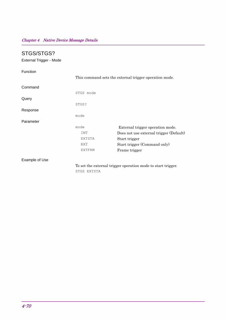
Chapter 4 Native Device Message Details
4-70
STGS/STGS? External Trigger - Mode
Function
This command sets the external trigger operation mode.
Command
STGS mode
Query
STGS?
Response
mode
Parameter
mode External trigger operation mode.
INT Does not use external trigger (Default) EXTSTA Start trigger EXT Start trigger (Command only)
EXTFRM Frame trigger
Example of Use
To set the external trigger operation mode to start trigger. STGS EXTSTA

Chapter 4 Native Device Message Details
4-71
4
Native D
evice Message D
etails
SYS/SYS? Application Switch Command/Application Status Query
Function
This command sets the operation target (application) to the signal generator. The execution status of the specified application is returned in response to a query.
Command
SYS SG,window
Query
SYS? SG
Response
status,window
Parameter
window Window status (optional) ACT Active (brought to front) INACT Inactive MIN Minimized NON No window displayed (response only) When omitted Same as ACT
status Application status CURRENT Operation target IDLE Loaded but not executed RUN Executed but not targeted for operation UNLOAD Not loaded
Example of Use
To switch the operation target to the signal generator. SYS SG,ACT
Chapter 4 Native Device Message Details
4-72 .
VDSPL/VDSPL? Volt Unit Display
Function
This command sets the display method when the output level is set in voltage units.
Command
VDSPL unit
Query
VDSPL?
Response
unit
Parameter
unit Voltage unit display system
EMF Open circuit voltage display TERM Termination voltage display
Example of Use
To display the voltage units using open voltage. VDSPL EMF
WMSPC? Waveform Memory Space Query
Function
This command queries the waveform memory free space.
Query
WMSPC?
Response
blank,consecutive_blank,total
Parameter
blank Free space (in byte) consecutive_blank Contiguous free space (in byte) total Total waveform memory size (in byte)
Example of Use
To query the waveform memory free space.