joint development of a fourth generation single crystal … · 2013-04-10 · joint development of...
TRANSCRIPT

S. WalstonGE Aircraft Engines, Cincinnati, Ohio
A. CetelPratt & Whitney, East Hartford, Connecticut
R. MacKayGlenn Research Center, Cleveland, Ohio
K. O’HaraGE Aircraft Engines, Lynn, Massachusetts
D. DuhlPratt & Whitney, East Hartford, Connecticut
R. DreshfieldGlenn Research Center, Cleveland, Ohio
Joint Development of a Fourth GenerationSingle Crystal Superalloy
NASA/TM—2004-213062
December 2004
https://ntrs.nasa.gov/search.jsp?R=20050019231 2020-03-01T11:21:16+00:00Z
The NASA STI Program Office . . . in Profile
Since its founding, NASA has been dedicated tothe advancement of aeronautics and spacescience. The NASA Scientific and TechnicalInformation (STI) Program Office plays a key partin helping NASA maintain this important role.
The NASA STI Program Office is operated byLangley Research Center, the Lead Center forNASA’s scientific and technical information. TheNASA STI Program Office provides access to theNASA STI Database, the largest collection ofaeronautical and space science STI in the world.The Program Office is also NASA’s institutionalmechanism for disseminating the results of itsresearch and development activities. These resultsare published by NASA in the NASA STI ReportSeries, which includes the following report types:
• TECHNICAL PUBLICATION. Reports ofcompleted research or a major significantphase of research that present the results ofNASA programs and include extensive dataor theoretical analysis. Includes compilationsof significant scientific and technical data andinformation deemed to be of continuingreference value. NASA’s counterpart of peer-reviewed formal professional papers buthas less stringent limitations on manuscriptlength and extent of graphic presentations.
• TECHNICAL MEMORANDUM. Scientificand technical findings that are preliminary orof specialized interest, e.g., quick releasereports, working papers, and bibliographiesthat contain minimal annotation. Does notcontain extensive analysis.
• CONTRACTOR REPORT. Scientific andtechnical findings by NASA-sponsoredcontractors and grantees.
• CONFERENCE PUBLICATION. Collectedpapers from scientific and technicalconferences, symposia, seminars, or othermeetings sponsored or cosponsored byNASA.
• SPECIAL PUBLICATION. Scientific,technical, or historical information fromNASA programs, projects, and missions,often concerned with subjects havingsubstantial public interest.
• TECHNICAL TRANSLATION. English-language translations of foreign scientificand technical material pertinent to NASA’smission.
Specialized services that complement the STIProgram Office’s diverse offerings includecreating custom thesauri, building customizeddatabases, organizing and publishing researchresults . . . even providing videos.
For more information about the NASA STIProgram Office, see the following:
• Access the NASA STI Program Home Pageat http://www.sti.nasa.gov
• E-mail your question via the Internet [email protected]
• Fax your question to the NASA AccessHelp Desk at 301–621–0134
• Telephone the NASA Access Help Desk at301–621–0390
• Write to: NASA Access Help Desk NASA Center for AeroSpace Information 7121 Standard Drive Hanover, MD 21076
S. WalstonGE Aircraft Engines, Cincinnati, Ohio
A. CetelPratt & Whitney, East Hartford, Connecticut
R. MacKayGlenn Research Center, Cleveland, Ohio
K. O’HaraGE Aircraft Engines, Lynn, Massachusetts
D. DuhlPratt & Whitney, East Hartford, Connecticut
R. DreshfieldGlenn Research Center, Cleveland, Ohio
Joint Development of a Fourth GenerationSingle Crystal Superalloy
NASA/TM—2004-213062
December 2004
National Aeronautics andSpace Administration
Glenn Research Center
Prepared for the10th International Symposium on Superalloyscosponsored by the Seven Springs International Symposium Committee,the Minerals, Metals, and Materials Society (TMS), the TMS HighTemperature Alloys Committee, and ASM InternationalChampion, Pennsylvania, September 19–23, 2004
Acknowledgments
The authors would like to thank the team of Bob Draper and Ajay Misra at NASA, Ben Bartlett at P&W andNorm Lindblad and Andy Johnson at GEAE for their guidance and leadership throughout the HSCT program.
This was a complex, multi-year, alloy development program and due to space limitations, this paper wasnot able to report on much of the excellent work conducted. This included phase extraction studies byDr. Robert Dreshfield at NASA, creep rupture mechanism analysis by Dr. Robert Field at Los Alamos
and heat treat effects and SRZ mitigation by Dr. Rebecca MacKay at NASA.Finally, the GEAE authors would like to thank Earl Ross and
Gary McCabe for their contributions.
Available from
NASA Center for Aerospace Information7121 Standard DriveHanover, MD 21076
National Technical Information Service5285 Port Royal RoadSpringfield, VA 22100
Trade names or manufacturers’ names are used in this report foridentification only. This usage does not constitute an officialendorsement, either expressed or implied, by the National
Aeronautics and Space Administration.
Available electronically at http://gltrs.grc.nasa.gov

JOINT DEVELOPMENT OF A FOURTH GENERATION SINGLE CRYSTAL SUPERALLOY
Abstract
A new, fourth generation, single crystal superalloy has been jointly developed by GE Aircraft Engines, Pratt & Whitney and NASA. The focus of the effort was to develop a turbine airfoil alloy with long-term durability for use in the High Speed Civil Transport. In order to achieve adequate long-time strength improvements at moderate temperatures and retain good microstructural stability, it was necessary to make significant composition changes from 2nd and 3rd generation single crystal superalloys. These included lower chromium levels, higher cobalt and rhenium levels and the inclusion of a new alloying element, ruthenium. It was found that higher Co levels were beneficial to reducing both TCP precipitation and SRZ formation. Ruthenium caused the refractory elements to partition more strongly to the γ’ phase, which resulted in better overall alloy stability. The final alloy, EPM-102, had significant creep rupture and fatigue improvements over the baseline production alloys and had acceptable microstructural stability. The alloy is currently being engine tested and evaluated for advanced engine applications.
Introduction This alloy development effort was conducted under the Enabling Propulsion Materials (EPM) program of the High Speed Civil Transport (HSCT) project sponsored by NASA. In contrast to subsonic engines, which accumulate hundreds of hot hours, the accumulated hot time of an HSCT engine was projected to be many thousands of hours and as a result, the alloy property goals centered around long-time, moderate (925-1050°C) temperature performance. Specifically, the alloy goals were to attain a 42°C benefit in creep rupture strength over the 2nd generation production turbine blade alloys, PWA 1484 and René N5, which were current at the program initiation in 1994. In addition, the alloy goals were to have sufficient microstructural stability to avoid degradation of long-time properties and acceptable environmental resistance and castability. Early studies by GEAE and P&W, as well as patent and literature searches, indicated that obtaining a balance of properties would be difficult. The occurrence of Secondary Reaction Zone (SRZ) in 3rd generation alloys was a newly discovered instability at thiat time [1] and needed to be addressed. It was known that increasing
the creep strength would require higher levels of refractory elements than that contained in 3rd generation alloys, which could lead to unacceptable levels of topologically close packed (TCP) phase formation. Ideas explored to improve stability included lowering Cr to 1% to accommodate higher refractory levels [2], increasing Co to 20% and adding Ru in order to affect the elemental partitioning and thereby improve microstructural stability [3]. As will be shown, Ru was determined to be a critical element to the success of the alloy development program as it could be added to achieve both improved microstructural stability and increased high temperature creep strength. Subsequent alloy development efforts by others [4-6] have led to similar conclusions on the usefulness of Ru in 4th generation single crystal superalloys.
Alloy Development Approach The HSCT mission cycle was projected to have the highest operating temperatures during the climb and supersonic cruise portion of the mission. This mission imposed unique requirements on the long-time stability and strength of the turbine airfoil alloys and had a strong influence on the alloy development approach and selection of the final alloy. Several rounds of development alloys were evaluated covering a wide range of compositions. Alloy compositions were derived as a result of various multiple regression analyses of prior alloys, as well as substantial use of neural networks. Typically, the neural networks gave considerably better predictive capability than the best multiple regression model constructed from the same data. The networks were trained using prior GEAE or P&W alloy data, and then EPM data was included as it became available. Several network node designs were typically used for each property, and the average of these networks was used to give a more robust and generalized prediction for future alloy properties. Each round of alloys was formulated using the design of experiments (DoE) approach. Most rounds were a fractional factorial design that allowed for the determination of individual elemental effects and elemental interactions. Candidate alloy properties were evaluated using single crystal slabs cast at either GEAE, Howmet or PCC. If necessary, trials were conducted to determine the proper solution heat treat cycle
NASA/TM—2004-213062 1
S. Walston,1 A. Cetel,3 R. MacKay,4 K. O’Hara,2 D. Duhl,3 and R. Dreshfield4 1GE Aircraft Engines, Cincinnati, Ohio 45215
2GE Aircraft Engines, Lynn, Massachusetts 01910 3Pratt & Whitney, East Hartford, Connecticut 06108
4National Aeronautics and Space Administration, Glenn Research Center, Cleveland, Ohio 44135
for each alloy and then a two-step aging heat treatment was utilized. Alloys were typically solution heat treated for 4-6 hours at 1315-1330°C depending on composition, and nearly complete solutioning was achieved in most alloys. For each round of alloy screening, there were several evaluations conducted, including:
• Microstructural stability (TCP) after 982°C and 1093°C exposure (furnace and creep)
• Internal cellular colony and SRZ stability evaluation • 982 to 1093°C stress rupture testing • 1177°C oxidation testing in Mach 1 burner rig
Limited 649°C tensile tests, hot corrosion tests and long-time stress rupture testing at 927 and 982°C were also used to gauge the alloys against the HSCT goals.
Compositional Effects on Microstructural Stability The effect of many different elements, including Cr, Al, Co, W, Re, Ru and Ta, on the formation of TCP and SRZ was studied
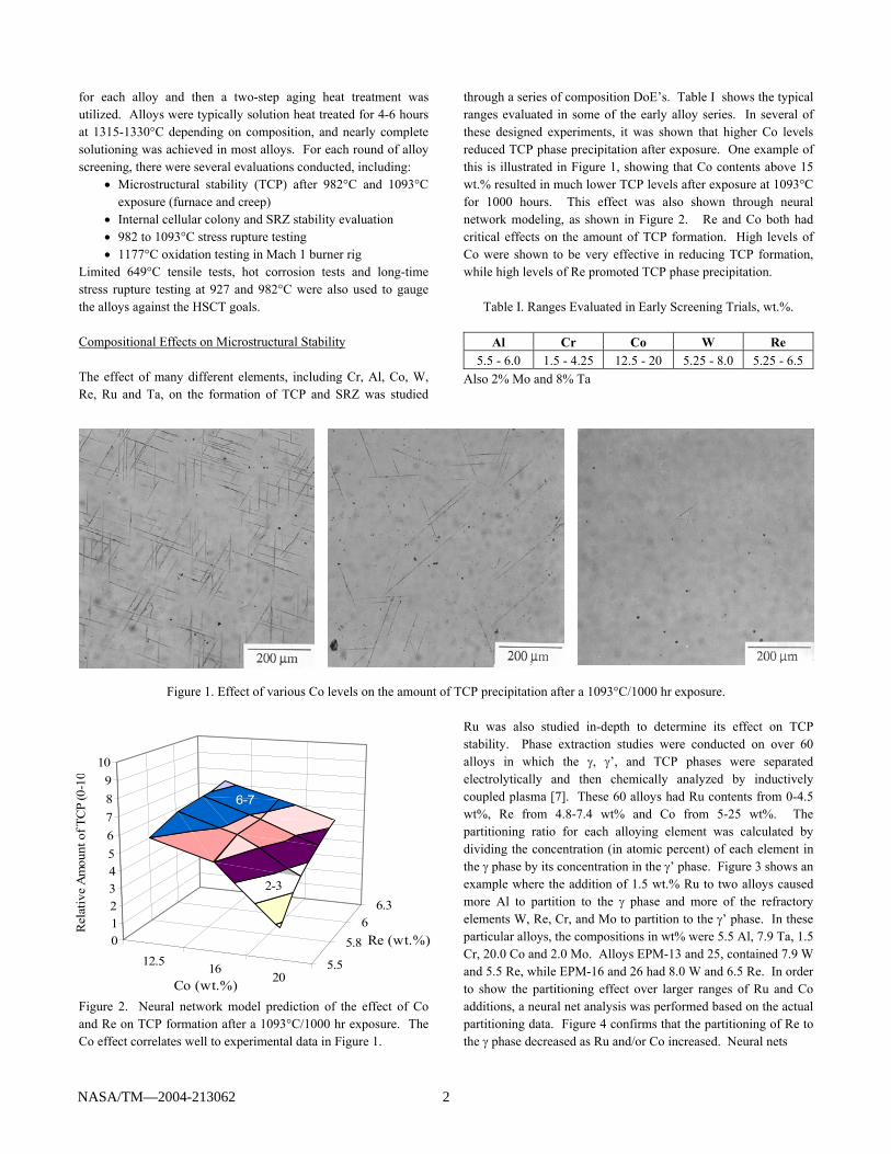
through a series of composition DoE’s. Table I shows the typical ranges evaluated in some of the early alloy series. In several of these designed experiments, it was shown that higher Co levels reduced TCP phase precipitation after exposure. One example of this is illustrated in Figure 1, showing that Co contents above 15 wt.% resulted in much lower TCP levels after exposure at 1093°C for 1000 hours. This effect was also shown through neural network modeling, as shown in Figure 2. Re and Co both had critical effects on the amount of TCP formation. High levels of Co were shown to be very effective in reducing TCP formation, while high levels of Re promoted TCP phase precipitation.
Table I. Ranges Evaluated in Early Screening Trials, wt.%.
Al Cr Co W Re 5.5 - 6.0 1.5 - 4.25 12.5 - 20 5.25 - 8.0 5.25 - 6.5
Also 2% Mo and 8% Ta
(a) 12.5 wt.% Co (b) 15 wt.% Co (c) 20 wt.% Co
Figure 1. Effect of various Co levels on the amount of TCP precipitation after a 1093°C/1000 hr exposure.
Figure 2. Neural network model prediction of the effect of Co and Re on TCP formation after a 1093°C/1000 hr exposure. The Co effect correlates well to experimental data in Figure 1.
Ru was also studied in-depth to determine its effect on TCP stability. Phase extraction studies were conducted on over 60 alloys in which the γ, γ’, and TCP phases were separated electrolytically and then chemically analyzed by inductively coupled plasma [7]. These 60 alloys had Ru contents from 0-4.5 wt%, Re from 4.8-7.4 wt% and Co from 5-25 wt%. The partitioning ratio for each alloying element was calculated by dividing the concentration (in atomic percent) of each element in the γ phase by its concentration in the γ’ phase. Figure 3 shows an example where the addition of 1.5 wt.% Ru to two alloys caused more Al to partition to the γ phase and more of the refractory elements W, Re, Cr, and Mo to partition to the γ’ phase. In these particular alloys, the compositions in wt% were 5.5 Al, 7.9 Ta, 1.5 Cr, 20.0 Co and 2.0 Mo. Alloys EPM-13 and 25, contained 7.9 W and 5.5 Re, while EPM-16 and 26 had 8.0 W and 6.5 Re. In order to show the partitioning effect over larger ranges of Ru and Co additions, a neural net analysis was performed based on the actual partitioning data. Figure 4 confirms that the partitioning of Re to the γ phase decreased as Ru and/or Co increased. Neural nets
12.5 1620
5.5
5.86
6.3
0123456789
10
Rel
ativ
e A
mou
nt o
f TC
P (0
-10
Co (wt.%)
Re (wt.%)
2-3
6-7
NASA/TM—2004-213062 2
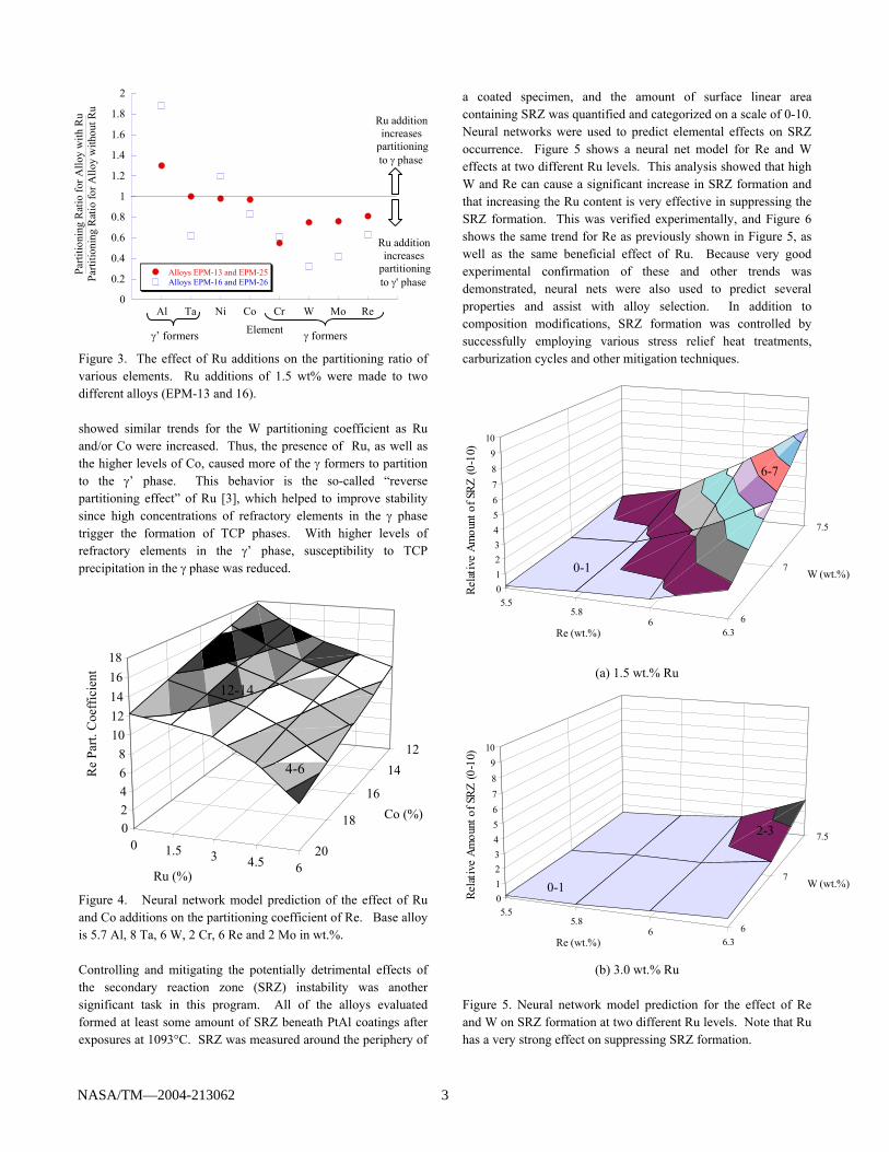
Figure 3. The effect of Ru additions on the partitioning ratio of various elements. Ru additions of 1.5 wt% were made to two different alloys (EPM-13 and 16). showed similar trends for the W partitioning coefficient as Ru and/or Co were increased. Thus, the presence of Ru, as well as the higher levels of Co, caused more of the γ formers to partition to the γ’ phase. This behavior is the so-called “reverse partitioning effect” of Ru [3], which helped to improve stability since high concentrations of refractory elements in the γ phase trigger the formation of TCP phases. With higher levels of refractory elements in the γ’ phase, susceptibility to TCP precipitation in the γ phase was reduced. Figure 4. Neural network model prediction of the effect of Ru and Co additions on the partitioning coefficient of Re. Base alloy is 5.7 Al, 8 Ta, 6 W, 2 Cr, 6 Re and 2 Mo in wt.%. Controlling and mitigating the potentially detrimental effects of the secondary reaction zone (SRZ) instability was another significant task in this program. All of the alloys evaluated formed at least some amount of SRZ beneath PtAl coatings after exposures at 1093°C. SRZ was measured around the periphery of
a coated specimen, and the amount of surface linear area containing SRZ was quantified and categorized on a scale of 0-10. Neural networks were used to predict elemental effects on SRZ occurrence. Figure 5 shows a neural net model for Re and W effects at two different Ru levels. This analysis showed that high W and Re can cause a significant increase in SRZ formation and that increasing the Ru content is very effective in suppressing the SRZ formation. This was verified experimentally, and Figure 6 shows the same trend for Re as previously shown in Figure 5, as well as the same beneficial effect of Ru. Because very good experimental confirmation of these and other trends was demonstrated, neural nets were also used to predict several properties and assist with alloy selection. In addition to composition modifications, SRZ formation was controlled by successfully employing various stress relief heat treatments, carburization cycles and other mitigation techniques.
(a) 1.5 wt.% Ru
(b) 3.0 wt.% Ru
Figure 5. Neural network model prediction for the effect of Re and W on SRZ formation at two different Ru levels. Note that Ru has a very strong effect on suppressing SRZ formation.
0 1.5 3 4.5 620
18
16
1412
02468
1012141618
Re
Part.
Coe
ffic
ient
Ru (%)
Co (%)
5.55.8
66.3
6
7
7.5
0123456789
10
Re (wt.%)
W (wt.%)
5.55.8
66.3
6
7
7.5
0123456789
10
Re (wt.%)
W (wt.%)
4-6
12-14
Relat
ive
Amou
nt o
f SRZ
(0-1
0)
0-1
2-3
Relat
ive
Amou
nt o
f SRZ
(0-1
0)6-7
0-1
0
0.2
0.4
0.6
0.8
1
1.2
1.4
1.6
1.8
2
Al Ta Ni Co Cr W Mo Re
Alloys EPM-13 and EPM-25Alloys EPM-16 and EPM-26
Parti
tioni
ng R
atio
for A
lloy
with
Ru
Parti
tioni
ng R
atio
for A
lloy
with
out R
u
Element
Ru additionincreases
partitioningto γ phase
Ru additionincreases
partitioningto γ' phase
γ formers γ’ formers
NASA/TM—2004-213062 3
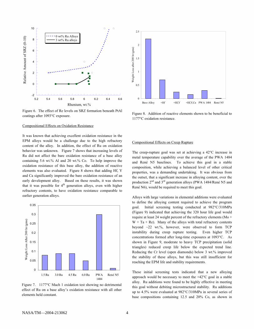
Figure 6. The effect of Re levels on SRZ formation beneath PtAl coatings after 1093°C exposure. Compositional Effects on Oxidation Resistance It was known that achieving excellent oxidation resistance in the EPM alloys would be a challenge due to the high refractory
content of the alloy. In addition, the effect of Ru on oxidation
behavior was unknown. Figure 7 shows that increasing levels of Ru did not affect the bare oxidation resistance of a base alloy containing 5.6 wt.% Al and 20 wt.% Co. To help improve the
oxidation resistance of this base alloy, the addition of reactive elements was also evaluated. Figure 8 shows that adding Hf, Y and Ca significantly improved the bare oxidation resistance of an
early development alloy. Based on these results, it was shown that it was possible for 4th generation alloys, even with higher refractory contents, to have oxidation resistance comparable to
earlier generation alloys. Figure 7. 1177°C Mach 1 oxidation test showing no detrimental effect of Ru on a base alloy’s oxidation resistance with all other elements held constant.
Figure 8. Addition of reactive elements shown to be beneficial to 1177°C oxidation resistance.
Compositional Effects on Creep Rupture The creep-rupture goal was set at achieving a 42°C increase in metal temperature capability over the average of the PWA 1484 and René N5 baselines. To achieve this goal in a stable composition, while achieving a balanced level of other critical properties, was a demanding undertaking. It was obvious from the outset, that a significant increase in alloying content, over the production 2nd and 3rd generation alloys (PWA 1484/René N5 and René N6), would be required to meet this goal. Alloys with large variations in elemental additions were evaluated to define the alloying content required to achieve the program goal. Initial screening testing conducted at 982°C/310MPa (Figure 9) indicated that achieving the 320 hour life goal would require at least 24 weight percent of the refractory elements (Mo + W + Ta + Re). Many of the alloys with total refractory contents beyond ~22 wt.%, however, were observed to form TCP instability during creep rupture testing. Even higher TCP concentrations formed after long-time exposures at 1093°C. As shown in Figure 9, moderate to heavy TCP precipitation (solid triangles) reduced creep life below the expected trend line. Reducing the Cr level (open diamonds) below 3 wt.% improved the stability of these alloys, but this was still insufficient for reaching the EPM life and stability requirements. These initial screening tests indicated that a new alloying approach would be necessary to meet the +42°C goal in a stable alloy. Ru additions were found to be highly effective in meeting this goal without debiting microstructural stability. Ru additions up to 4.5% were evaluated at 982°C/310MPa in several series of base compositions containing 12.5 and 20% Co, as shown in
0
0.5
1
1.5
2
2.5
Base Alloy +Hf +Hf,Y +Hf,Y,Ca PWA 1484 René N5
Wei
ght L
oss a
fter 2
00 h
r (gm
s)
-2
0
2
4
6
8
10
5.2 5.4 5.6 5.8 6 6.2 6.4 6.6
0 wt% Ru Alloys3 wt% Ru alloys
Rel
ativ
e A
mou
nt o
f SRZ
(0-1
0)
Rhenium, wt.%
0
0.05
0.1
0.15
0.2
0.25
0.3
0.35
1.5 Ru 3.0 Ru 4.5 Ru 6.0 Ru PWA1484
René N5
Wei
ght L
oss A
fter 2
00 h
r (gm
s)
NASA/TM—2004-213062 4
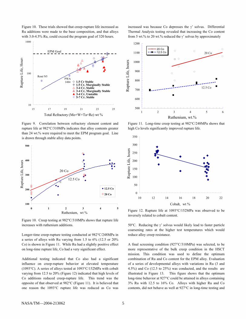
Figure 10. These trials showed that creep-rupture life increased as Ru additions were made to the base composition, and that alloys with 3.0-4.5% Ru, could exceed the program goal of 320 hours. Figure 9. Correlation between refractory element content and rupture life at 982°C/310MPa indicates that alloy contents greater than 24 wt.% were required to meet the EPM program goal. Line is drawn through stable alloy data points. Figure 10. Creep testing at 982°C/310MPa shows that rupture life increases with ruthenium additions. Longer-time creep-rupture testing conducted at 982°C/248MPa in a series of alloys with Ru varying from 1.5 to 6% (12.5 or 20% Co) is shown in Figure 11. While Ru had a slightly positive effect on long-time rupture life, Co had a very significant effect. Additional testing indicated that Co also had a significant influence on creep-rupture behavior at elevated temperature (1093°C). A series of alloys tested at 1093°C/152MPa with cobalt varying from 12.5 to 20% (Figure 12) indicated that high levels of Co additions reduced creep-rupture life. This trend was the opposite of that observed at 982°C (Figure 11). It is believed that one reason the 1093°C rupture life was reduced as Co was
increased was because Co depresses the γ’ solvus. Differential Thermal Analysis testing revealed that increasing the Co content from 5 wt.% to 20 wt.% reduced the γ’ solvus by approximately Figure 11. Long-time creep testing at 982°C/248MPa shows that high Co levels significantly improved rupture life. Figure 12. Rupture life at 1093°C/152MPa was observed to be inversely related to cobalt content. 50°C. Reducing the γ’ solvus would likely lead to faster particle coarsening rates at the higher test temperatures which would reduce alloy creep resistance. A final screening condition (927°C/310MPa) was selected, to be more representative of the bulk creep condition in the HSCT mission. This condition was used to define the optimum combination of Ru and Co content for the EPM alloy. Evaluation of a series of developmental alloys with variations in Ru (3 and 4.5%) and Co (12.5 to 25%) was conducted, and the results are illustrated in Figure 13. This figure shows that the optimum long-time behavior at 927°C could be attained in alloys containing 3% Ru with 12.5 to 16% Co. Alloys with higher Ru and Co contents, did not behave as well at 927°C in long-time testing and
0
50
100
150
200
250
300
350
10 12 14 16 18 20 22
Cobalt, wt %
Rup
ture
Life
, hou
rs
20 Co
12.5 Co
PWA 1484
René N5
EPM Goal
500
600
700
800
900
1000
1100
1200
1 2 3 4 5 6
20 Co12.5 Co
Rup
ture
Life
, hou
rs
Ruthenium, wt.%
20 Co
12.5 Co
100
200
300
400
500
0 1 2 3 4 5Ruthenium, wt %
12.5 Co
20 Co
Rup
ture
Life
, hou
rs
10
100
1000
15 17 19 21 23 25
Total Refractory (Mo+W+Ta+Re) wt %
Rup
ture
Life
, Hou
rs
1.5 Cr Stable1.5 Cr, Marginally Stable3-4 Cr, Stable3-4 Cr, Marginally Stable3-4 Cr, Unstable5-7 Cr, Stable
NASA/TM—2004-213062 5
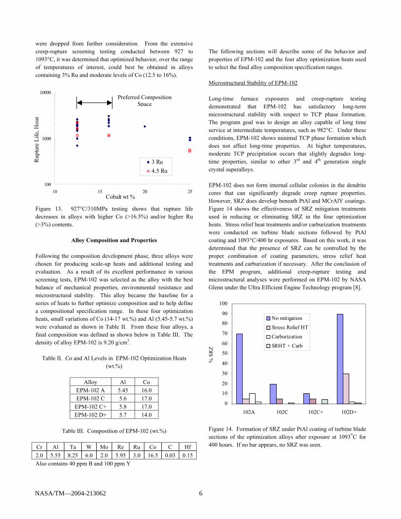
were dropped from further consideration. From the extensive creep-rupture screening testing conducted between 927 to 1093°C, it was determined that optimized behavior, over the range of temperatures of interest, could best be obtained in alloys containing 3% Ru and moderate levels of Co (12.5 to 16%). Figure 13. 927°C/310MPa testing shows that rupture life decreases in alloys with higher Co (>16.5%) and/or higher Ru (>3%) contents.
Alloy Composition and Properties Following the composition development phase, three alloys were chosen for producing scale-up heats and additional testing and evaluation. As a result of its excellent performance in various screening tests, EPM-102 was selected as the alloy with the best balance of mechanical properties, environmental resistance and microstructural stability. This alloy became the baseline for a series of heats to further optimize composition and to help define a compositional specification range. In these four optimization heats, small variations of Co (14-17 wt.%) and Al (5.45-5.7 wt.%) were evaluated as shown in Table II. From these four alloys, a final composition was defined as shown below in Table III. The density of alloy EPM-102 is 9.20 g/cm3.
Table II. Co and Al Levels in EPM-102 Optimization Heats (wt.%)
Alloy Al Co
EPM-102 A 5.45 16.0 EPM-102 C 5.6 17.0
EPM-102 C+ 5.8 17.0 EPM-102 D+ 5.7 14.0
Table III. Composition of EPM-102 (wt.%)
Cr Al Ta W Mo Re Ru Co C Hf 2.0 5.55 8.25 6.0 2.0 5.95 3.0 16.5 0.03 0.15 Also contains 40 ppm B and 100 ppm Y
The following sections will describe some of the behavior and properties of EPM-102 and the four alloy optimization heats used to select the final alloy composition specification ranges. Microstructural Stability of EPM-102 Long-time furnace exposures and creep-rupture testing demonstrated that EPM-102 has satisfactory long-term microstructural stability with respect to TCP phase formation. The program goal was to design an alloy capable of long time service at intermediate temperatures, such as 982°C. Under these conditions, EPM-102 shows minimal TCP phase formation which does not affect long-time properties. At higher temperatures, moderate TCP precipitation occurs that slightly degrades long-time properties, similar to other 3rd and 4th generation single crystal superalloys. EPM-102 does not form internal cellular colonies in the dendrite cores that can significantly degrade creep rupture properties. However, SRZ does develop beneath PtAl and MCrAlY coatings. Figure 14 shows the effectiveness of SRZ mitigation treatments used in reducing or eliminating SRZ in the four optimization heats. Stress relief heat treatments and/or carburization treatments were conducted on turbine blade sections followed by PtAl coating and 1093°C/400 hr exposures. Based on this work, it was determined that the presence of SRZ can be controlled by the proper combination of coating parameters, stress relief heat treatments and carburization if necessary. After the conclusion of the EPM program, additional creep-rupture testing and microstructural analyses were performed on EPM-102 by NASA Glenn under the Ultra Efficient Engine Technology program [8]. Figure 14. Formation of SRZ under PtAl coating of turbine blade sections of the optimization alloys after exposure at 1093°C for 400 hours. If no bar appears, no SRZ was seen.
Preferred Composition Space
0
10
20
30
40
50
60
70
80
90
100
102A 102C 102C+ 102D+
% S
RZ
No mitigation
Stress Relief HT
Carburization
SRHT + Carb
100
1000
10000
10 15 20 25Cobalt wt %
Rup
ture
Life
, Hou
r
3 Ru4.5 Ru
NASA/TM—2004-213062 6
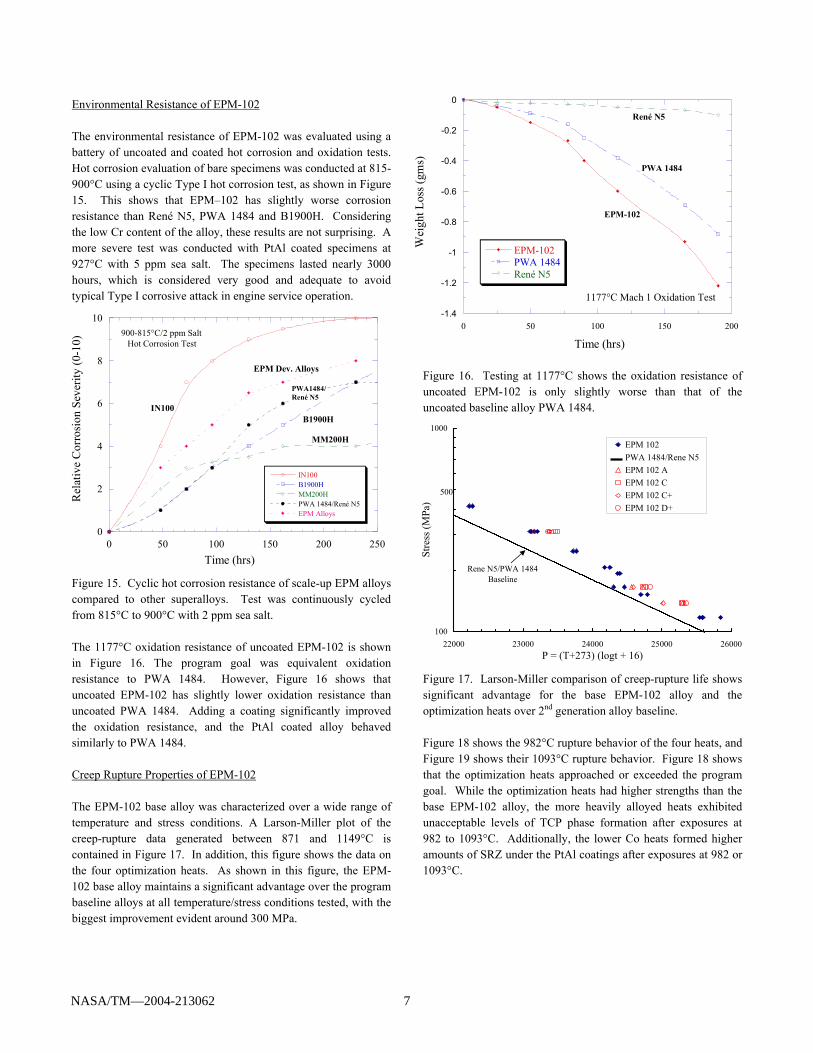
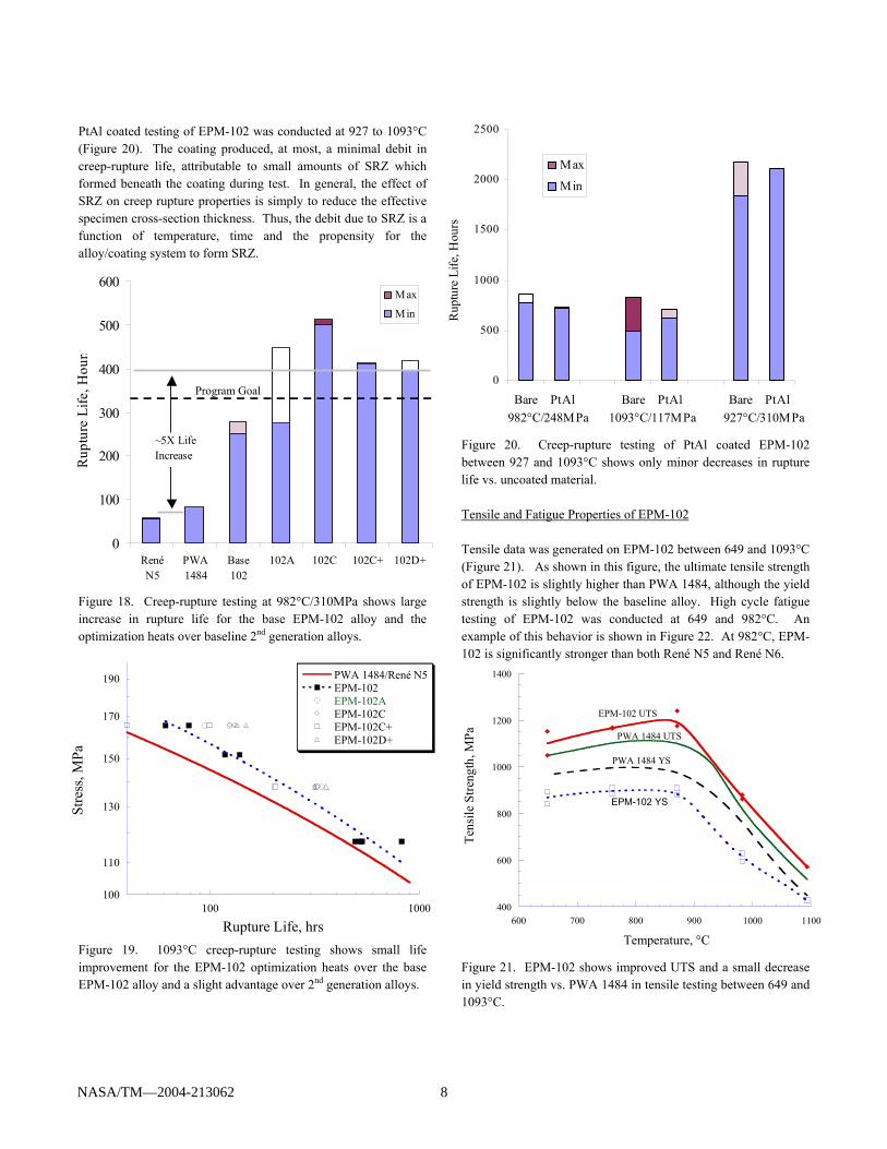
Environmental Resistance of EPM-102 The environmental resistance of EPM-102 was evaluated using a battery of uncoated and coated hot corrosion and oxidation tests. Hot corrosion evaluation of bare specimens was conducted at 815-900°C using a cyclic Type I hot corrosion test, as shown in Figure 15. This shows that EPM–102 has slightly worse corrosion resistance than René N5, PWA 1484 and B1900H. Considering the low Cr content of the alloy, these results are not surprising. A more severe test was conducted with PtAl coated specimens at 927°C with 5 ppm sea salt. The specimens lasted nearly 3000 hours, which is considered very good and adequate to avoid typical Type I corrosive attack in engine service operation. Figure 15. Cyclic hot corrosion resistance of scale-up EPM alloys compared to other superalloys. Test was continuously cycled from 815°C to 900°C with 2 ppm sea salt. The 1177°C oxidation resistance of uncoated EPM-102 is shown in Figure 16. The program goal was equivalent oxidation resistance to PWA 1484. However, Figure 16 shows that uncoated EPM-102 has slightly lower oxidation resistance than uncoated PWA 1484. Adding a coating significantly improved the oxidation resistance, and the PtAl coated alloy behaved similarly to PWA 1484. Creep Rupture Properties of EPM-102 The EPM-102 base alloy was characterized over a wide range of temperature and stress conditions. A Larson-Miller plot of the creep-rupture data generated between 871 and 1149°C is contained in Figure 17. In addition, this figure shows the data on the four optimization heats. As shown in this figure, the EPM-102 base alloy maintains a significant advantage over the program baseline alloys at all temperature/stress conditions tested, with the biggest improvement evident around 300 MPa.
Figure 16. Testing at 1177°C shows the oxidation resistance of uncoated EPM-102 is only slightly worse than that of the uncoated baseline alloy PWA 1484. Figure 17. Larson-Miller comparison of creep-rupture life shows significant advantage for the base EPM-102 alloy and the optimization heats over 2nd generation alloy baseline. Figure 18 shows the 982°C rupture behavior of the four heats, and Figure 19 shows their 1093°C rupture behavior. Figure 18 shows that the optimization heats approached or exceeded the program goal. While the optimization heats had higher strengths than the base EPM-102 alloy, the more heavily alloyed heats exhibited unacceptable levels of TCP phase formation after exposures at 982 to 1093°C. Additionally, the lower Co heats formed higher amounts of SRZ under the PtAl coatings after exposures at 982 or 1093°C.
0
2
4
6
8
10
0 50 100 150 200 250
IN100B1900HMM200HPWA 1484/René N5EPM Alloys
Rel
ativ
e C
orro
sion
Sev
erity
(0-1
0)
Time (hrs)
IN100
EPM Dev. Alloys
PWA1484/René N5
B1900H
MM200H
900-815°C/2 ppm Salt Hot Corrosion Test
-1.4
-1.2
-1
-0.8
-0.6
-0.4
-0.2
0
0 50 100 150 200
EPM-102PWA 1484René N5
Wei
ght L
oss (
gms)
Time (hrs)
René N5
PWA 1484
EPM-102
1177°C Mach 1 Oxidation Test
100
1000
22000 23000 24000 25000 26000P = (T+273) (logt + 16)
Stre
ss (M
Pa)
EPM 102 PWA 1484/Rene N5 EPM 102 A EPM 102 C EPM 102 C+ EPM 102 D+
Rene N5/PWA 1484 Baseline
500
NASA/TM—2004-213062 7
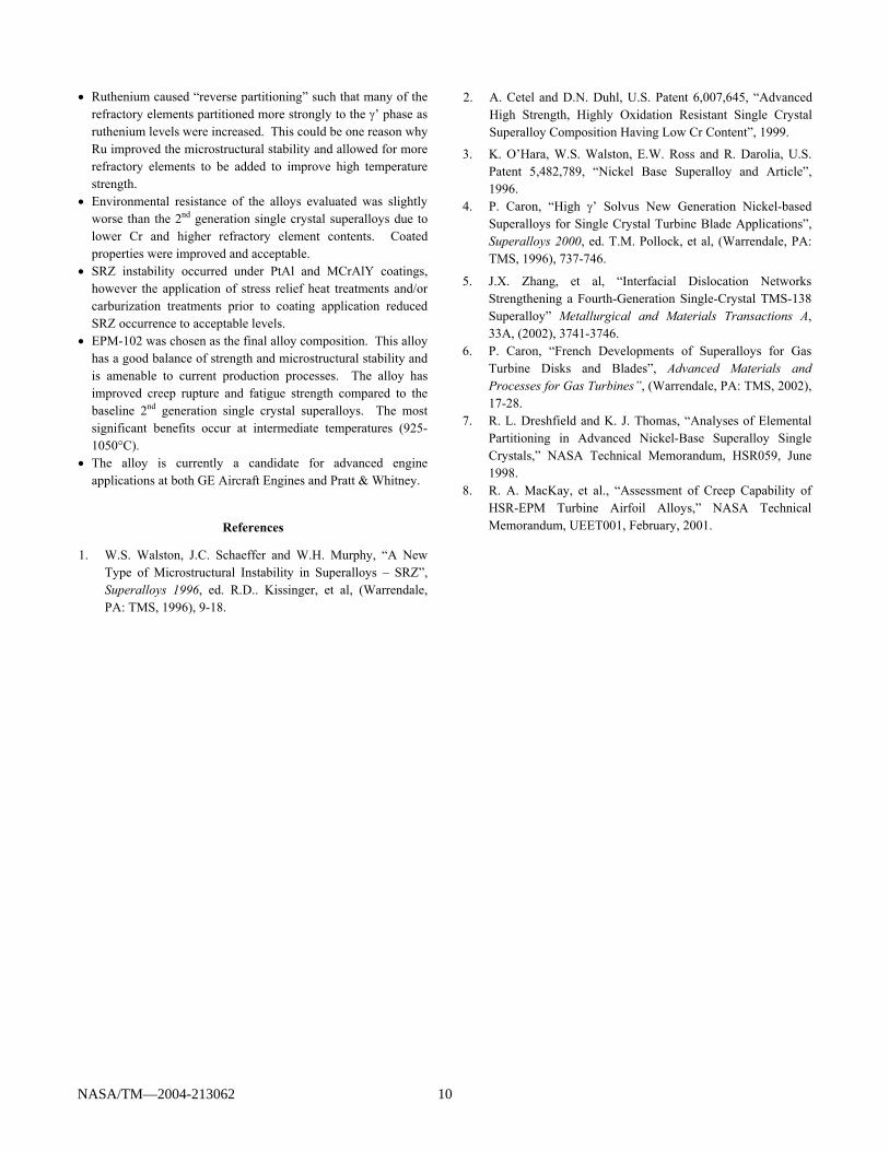
PtAl coated testing of EPM-102 was conducted at 927 to 1093°C (Figure 20). The coating produced, at most, a minimal debit in creep-rupture life, attributable to small amounts of SRZ which formed beneath the coating during test. In general, the effect of SRZ on creep rupture properties is simply to reduce the effective specimen cross-section thickness. Thus, the debit due to SRZ is a function of temperature, time and the propensity for the alloy/coating system to form SRZ. Figure 18. Creep-rupture testing at 982°C/310MPa shows large increase in rupture life for the base EPM-102 alloy and the optimization heats over baseline 2nd generation alloys. Figure 19. 1093°C creep-rupture testing shows small life improvement for the EPM-102 optimization heats over the base EPM-102 alloy and a slight advantage over 2nd generation alloys.
Figure 20. Creep-rupture testing of PtAl coated EPM-102 between 927 and 1093°C shows only minor decreases in rupture life vs. uncoated material. Tensile and Fatigue Properties of EPM-102 Tensile data was generated on EPM-102 between 649 and 1093°C (Figure 21). As shown in this figure, the ultimate tensile strength of EPM-102 is slightly higher than PWA 1484, although the yield strength is slightly below the baseline alloy. High cycle fatigue testing of EPM-102 was conducted at 649 and 982°C. An example of this behavior is shown in Figure 22. At 982°C, EPM-102 is significantly stronger than both René N5 and René N6. Figure 21. EPM-102 shows improved UTS and a small decrease in yield strength vs. PWA 1484 in tensile testing between 649 and 1093°C.
0
100
200
300
400
500
600
RenéN5
PWA1484
Base102
102A 102C 102C+ 102D+
Rup
ture
Life
, Hou
rs
Max
Min
~5X LifeIncrease
100
110
130
150
170
190
100 1000
PWA 1484/René N5EPM-102EPM-102AEPM-102CEPM-102C+EPM-102D+
Rupture Life, hrs
Stre
ss, M
Pa
400
600
800
1000
1200
1400
600 700 800 900 1000 1100
Tens
ile S
treng
th, M
Pa
Temperature, °C
EPM-102 UTS
PWA 1484 UTS
PWA 1484 YS
EPM-102 YS
Program Goal 0
500
1000
1500
2000
2500
Bare PtAl Bare PtAl Bare PtAl
Max
Min
Rup
ture
Life
, Hou
rs
982°C/248MPa 1093°C/117MPa 927°C/310MPa
NASA/TM—2004-213062 8
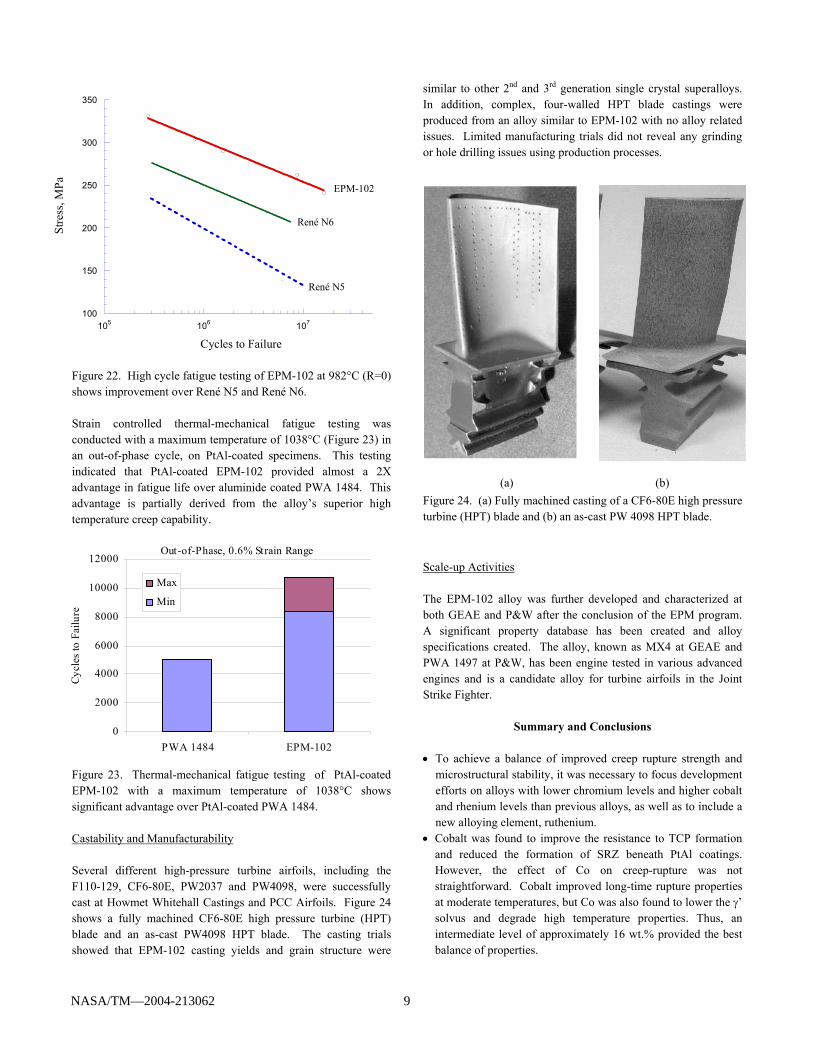
Figure 22. High cycle fatigue testing of EPM-102 at 982°C (R=0) shows improvement over René N5 and René N6. Strain controlled thermal-mechanical fatigue testing was conducted with a maximum temperature of 1038°C (Figure 23) in an out-of-phase cycle, on PtAl-coated specimens. This testing indicated that PtAl-coated EPM-102 provided almost a 2X advantage in fatigue life over aluminide coated PWA 1484. This advantage is partially derived from the alloy’s superior high temperature creep capability. Figure 23. Thermal-mechanical fatigue testing of PtAl-coated EPM-102 with a maximum temperature of 1038°C shows significant advantage over PtAl-coated PWA 1484. Castability and Manufacturability Several different high-pressure turbine airfoils, including the F110-129, CF6-80E, PW2037 and PW4098, were successfully cast at Howmet Whitehall Castings and PCC Airfoils. Figure 24 shows a fully machined CF6-80E high pressure turbine (HPT) blade and an as-cast PW4098 HPT blade. The casting trials showed that EPM-102 casting yields and grain structure were
similar to other 2nd and 3rd generation single crystal superalloys. In addition, complex, four-walled HPT blade castings were produced from an alloy similar to EPM-102 with no alloy related issues. Limited manufacturing trials did not reveal any grinding or hole drilling issues using production processes.
(a)
(b) Figure 24. (a) Fully machined casting of a CF6-80E high pressure turbine (HPT) blade and (b) an as-cast PW 4098 HPT blade.
Scale-up Activities The EPM-102 alloy was further developed and characterized at both GEAE and P&W after the conclusion of the EPM program. A significant property database has been created and alloy specifications created. The alloy, known as MX4 at GEAE and PWA 1497 at P&W, has been engine tested in various advanced engines and is a candidate alloy for turbine airfoils in the Joint Strike Fighter.
Summary and Conclusions • To achieve a balance of improved creep rupture strength and
microstructural stability, it was necessary to focus development efforts on alloys with lower chromium levels and higher cobalt and rhenium levels than previous alloys, as well as to include a new alloying element, ruthenium.
• Cobalt was found to improve the resistance to TCP formation and reduced the formation of SRZ beneath PtAl coatings. However, the effect of Co on creep-rupture was not straightforward. Cobalt improved long-time rupture properties at moderate temperatures, but Co was also found to lower the γ’ solvus and degrade high temperature properties. Thus, an intermediate level of approximately 16 wt.% provided the best balance of properties.
0
2000
4000
6000
8000
10000
12000
PWA 1484 EPM-102
Cycl
es to
Fai
lure
Max
Min
Out-of-Phase, 0.6% Strain Range
100
150
200
250
300
350
105 106 107
Stre
ss, M
Pa
Cycles to Failure
EPM-102
René N6
René N5
NASA/TM—2004-213062 9
• Ruthenium caused “reverse partitioning” such that many of the refractory elements partitioned more strongly to the γ’ phase as ruthenium levels were increased. This could be one reason why Ru improved the microstructural stability and allowed for more refractory elements to be added to improve high temperature strength.
• Environmental resistance of the alloys evaluated was slightly worse than the 2nd generation single crystal superalloys due to lower Cr and higher refractory element contents. Coated properties were improved and acceptable.
• SRZ instability occurred under PtAl and MCrAlY coatings, however the application of stress relief heat treatments and/or carburization treatments prior to coating application reduced SRZ occurrence to acceptable levels.
• EPM-102 was chosen as the final alloy composition. This alloy has a good balance of strength and microstructural stability and is amenable to current production processes. The alloy has improved creep rupture and fatigue strength compared to the baseline 2nd generation single crystal superalloys. The most significant benefits occur at intermediate temperatures (925-1050°C).
• The alloy is currently a candidate for advanced engine applications at both GE Aircraft Engines and Pratt & Whitney.
References
1. W.S. Walston, J.C. Schaeffer and W.H. Murphy, “A New Type of Microstructural Instability in Superalloys – SRZ”, Superalloys 1996, ed. R.D.. Kissinger, et al, (Warrendale, PA: TMS, 1996), 9-18.
2. A. Cetel and D.N. Duhl, U.S. Patent 6,007,645, “Advanced High Strength, Highly Oxidation Resistant Single Crystal Superalloy Composition Having Low Cr Content”, 1999.
3. K. O’Hara, W.S. Walston, E.W. Ross and R. Darolia, U.S. Patent 5,482,789, “Nickel Base Superalloy and Article”, 1996.
4. P. Caron, “High γ’ Solvus New Generation Nickel-based Superalloys for Single Crystal Turbine Blade Applications”, Superalloys 2000, ed. T.M. Pollock, et al, (Warrendale, PA: TMS, 1996), 737-746.
5. J.X. Zhang, et al, “Interfacial Dislocation Networks Strengthening a Fourth-Generation Single-Crystal TMS-138 Superalloy” Metallurgical and Materials Transactions A, 33A, (2002), 3741-3746.
6. P. Caron, “French Developments of Superalloys for Gas Turbine Disks and Blades”, Advanced Materials and Processes for Gas Turbines”, (Warrendale, PA: TMS, 2002), 17-28.
7. R. L. Dreshfield and K. J. Thomas, “Analyses of Elemental Partitioning in Advanced Nickel-Base Superalloy Single Crystals,” NASA Technical Memorandum, HSR059, June 1998.
8. R. A. MacKay, et al., “Assessment of Creep Capability of HSR-EPM Turbine Airfoil Alloys,” NASA Technical Memorandum, UEET001, February, 2001.
NASA/TM—2004-213062 10
This publication is available from the NASA Center for AeroSpace Information, 301–621–0390.
REPORT DOCUMENTATION PAGE
2. REPORT DATE
19. SECURITY CLASSIFICATION OF ABSTRACT
18. SECURITY CLASSIFICATION OF THIS PAGE
Public reporting burden for this collection of information is estimated to average 1 hour per response, including the time for reviewing instructions, searching existing data sources,gathering and maintaining the data needed, and completing and reviewing the collection of information. Send comments regarding this burden estimate or any other aspect of thiscollection of information, including suggestions for reducing this burden, to Washington Headquarters Services, Directorate for Information Operations and Reports, 1215 JeffersonDavis Highway, Suite 1204, Arlington, VA 22202-4302, and to the Office of Management and Budget, Paperwork Reduction Project (0704-0188), Washington, DC 20503.
NSN 7540-01-280-5500 Standard Form 298 (Rev. 2-89)Prescribed by ANSI Std. Z39-18298-102
Form Approved
OMB No. 0704-0188
12b. DISTRIBUTION CODE
8. PERFORMING ORGANIZATION REPORT NUMBER
5. FUNDING NUMBERS
3. REPORT TYPE AND DATES COVERED
4. TITLE AND SUBTITLE
6. AUTHOR(S)
7. PERFORMING ORGANIZATION NAME(S) AND ADDRESS(ES)
11. SUPPLEMENTARY NOTES
12a. DISTRIBUTION/AVAILABILITY STATEMENT
13. ABSTRACT (Maximum 200 words)
14. SUBJECT TERMS
17. SECURITY CLASSIFICATION OF REPORT
16. PRICE CODE
15. NUMBER OF PAGES
20. LIMITATION OF ABSTRACT
Unclassified Unclassified
Technical Memorandum
Unclassified
National Aeronautics and Space AdministrationJohn H. Glenn Research Center at Lewis FieldCleveland, Ohio 44135–3191
1. AGENCY USE ONLY (Leave blank)
10. SPONSORING/MONITORING AGENCY REPORT NUMBER
9. SPONSORING/MONITORING AGENCY NAME(S) AND ADDRESS(ES)
National Aeronautics and Space AdministrationWashington, DC 20546–0001
Available electronically at http://gltrs.grc.nasa.gov
December 2004
NASA TM—2004-213062
E–14524
WBS–22–714–04–06
16
Joint Development of a Fourth Generation Single Crystal Superalloy
S. Walston, A. Cetel, R. MacKay, K. O’Hara, D. Duhl, and R. Dreshfield
Superalloys; Single crystals; Mechanical properties; Creep rupture; Nickel;Ruthenium; Rhenium
Unclassified -UnlimitedSubject Category: 26 Distribution: Nonstandard
Prepared for the 10th International Symposium on Superalloys cosponsored by the Seven Springs International Symposium Committee,the Minerals, Metals, and Materials Society (TMS), the TMS High Temperature Alloys Committee, and ASM International, Champion,Pennsylvania, September 19–23, 2004. S. Walston, GE Aircraft Engines, Cincinnati, Ohio 45215; K. O'Hara, GE Aircraft Engines,Lynn, Massachusetts 01910; A. Cetel and D. Duhl, Pratt & Whitney, East Hartford, Connecticut 06108; R. MacKay and R. Dreshfield,NASA Glenn Research Center. Responsible person, R. MacKay, organization code 5100, 216–433–3269.
A new, fourth generation, single crystal superalloy has been jointly developed by GE Aircraft Engines, Pratt & Whitney,and NASA. The focus of the effort was to develop a turbine airfoil alloy with long-term durability for use in the HighSpeed Civil Transport. In order to achieve adequate long-time strength improvements at moderate temperatures andretain good microstructural stability, it was necessary to make significant composition changes from 2nd and 3rdgeneration single crystal superalloys. These included lower chromium levels, higher cobalt and rhenium levels and theinclusion of a new alloying element, ruthenium. It was found that higher Co levels were beneficial to reducing both TCPprecipitation and SRZ formation. Ruthenium caused the refractory elements to partition more strongly to the γ' phase,which resulted in better overall alloy stability. The final alloy, EPM–102, had significant creep rupture and fatigueimprovements over the baseline production alloys and had acceptable microstructural stability. The alloy is currentlybeing engine tested and evaluated for advanced engine applications.

