group 33 front suspension -...
TRANSCRIPT
33-1
GROUP 33
FRONT SUSPENSION
CONTENTS
GENERAL DESCRIPTION. . . . . . . . . 33-2
FRONT SUSPENSION DIAGNOSIS . 33-2INTRODUCTION TO FRONT SUSPENSION DIAGNOSIS . . . . . . . . . . . . . . . . . . . . . . . . 33-2FRONT SUSPENSION DIAGNOSIS TROUBLESHOOTING STRATEGY . . . . . . 33-2SYMPTOM CHART. . . . . . . . . . . . . . . . . . . 33-3SYMPTOM PROCEDURES . . . . . . . . . . . . 33-3
SPECIAL TOOLS. . . . . . . . . . . . . . . . 33-5
ON-VEHICLE SERVICE. . . . . . . . . . . 33-6FRONT WHEEL ALIGNMENT CHECK AND ADJUSTMENT . . . . . . . . . . . . . . . . . . . . . . 33-6LOWER ARM BALL JOINT END PLAY CHECK . . . . . . . . . . . . . . . . . . . . . . . . . . . . 33-8BALL JOINT DUST COVER CHECK . . . . . 33-8
STRUT ASSEMBLY. . . . . . . . . . . . . . 33-9REMOVAL AND INSTALLATION . . . . . . . . 33-9INSPECTION . . . . . . . . . . . . . . . . . . . . . . . 33-9
DISASSEMBLY AND ASSEMBLY . . . . . . . 33-10INSPECTION. . . . . . . . . . . . . . . . . . . . . . . . 33-14
LOWER ARM . . . . . . . . . . . . . . . . . . . 33-15REMOVAL AND INSTALLATION . . . . . . . . 33-15INSPECTION. . . . . . . . . . . . . . . . . . . . . . . . 33-16LOWER ARM BALL JOINT DUST COVER REPLACEMENT . . . . . . . . . . . . . . . . . . . . . 33-17LOWER ARM BUSHING (REAR) REPLACEMENT . . . . . . . . . . . . . . . . . . . . . 33-18
STABILIZER BAR. . . . . . . . . . . . . . . . 33-20REMOVAL AND INSTALLATION . . . . . . . . 33-20INSPECTION. . . . . . . . . . . . . . . . . . . . . . . . 33-26
SPECIFICATIONS . . . . . . . . . . . . . . . 33-27FASTENER TIGHTENING SPECIFICATIONS. . . . . . . . . . . . . . . . . . . . 33-27GENERAL SPECIFICATIONS . . . . . . . . . . 33-28SERVICE SPECIFICATIONS . . . . . . . . . . . 33-28LUBRICANT . . . . . . . . . . . . . . . . . . . . . . . . 33-28
GENERAL DESCRIPTIONFRONT SUSPENSION33-2
GENERAL DESCRIPTIONM1332000100485
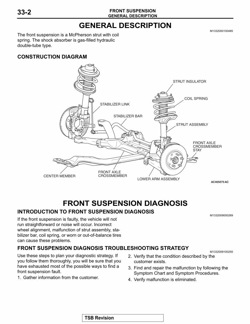
The front suspension is a McPherson strut with coil spring. The shock absorber is gas-filled hydraulic double-tube type.
CONSTRUCTION DIAGRAM
AC405075AC
STABILIZER BAR
COIL SPRING
STABILIZER LINK
STRUT ASSEMBLY
FRONT AXLE CROSSMEMBER
LOWER ARM ASSEMBLYCENTER MEMBER
FRONT AXLE CROSSMEMBER STAY
STRUT INSULATOR
FRONT SUSPENSION DIAGNOSISINTRODUCTION TO FRONT SUSPENSION DIAGNOSIS
M1332009000269If the front suspension is faulty, the vehicle will not run straightforward or noise will occur. Incorrect wheel alignment, malfunction of strut assembly, sta-bilizer bar, coil spring, or worn or out-of-balance tires can cause these problems.
FRONT SUSPENSION DIAGNOSIS TROUBLESHOOTING STRATEGYM1332009100255
Use these steps to plan your diagnostic strategy. If you follow them thoroughly, you will be sure that you have exhausted most of the possible ways to find a front suspension fault.1. Gather information from the customer.
2. Verify that the condition described by the customer exists.
3. Find and repair the malfunction by following the Symptom Chart and Symptom Procedures.
4. Verify malfunction is eliminated.
TSB Revision
FRONT SUSPENSION DIAGNOSISFRONT SUSPENSION 33-3
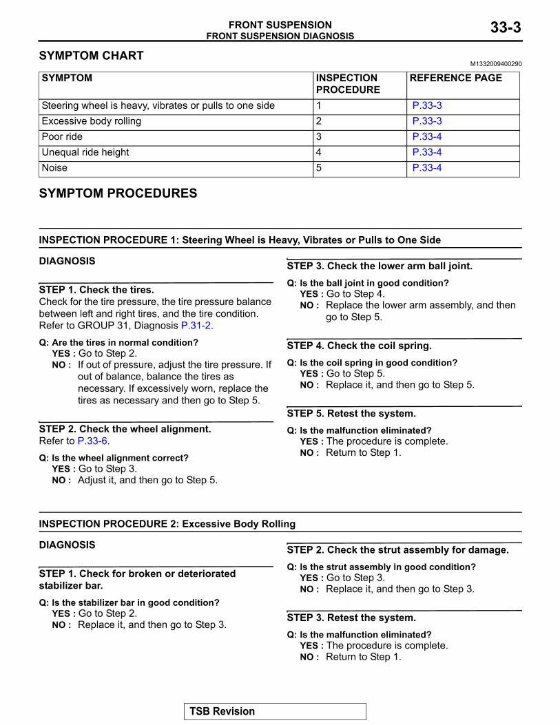
SYMPTOM CHARTM1332009400290
SYMPTOM INSPECTION PROCEDURE
REFERENCE PAGE
Steering wheel is heavy, vibrates or pulls to one side 1 P.33-3Excessive body rolling 2 P.33-3Poor ride 3 P.33-4Unequal ride height 4 P.33-4Noise 5 P.33-4
SYMPTOM PROCEDURES
INSPECTION PROCEDURE 1: Steering Wheel is Heavy, Vibrates or Pulls to One Side
DIAGNOSIS
STEP 1. Check the tires.Check for the tire pressure, the tire pressure balance between left and right tires, and the tire condition. Refer to GROUP 31, Diagnosis P.31-2.
Q: Are the tires in normal condition?YES : Go to Step 2.NO : If out of pressure, adjust the tire pressure. If
out of balance, balance the tires as necessary. If excessively worn, replace the tires as necessary and then go to Step 5.
STEP 2. Check the wheel alignment.Refer to P.33-6.
Q: Is the wheel alignment correct?YES : Go to Step 3.NO : Adjust it, and then go to Step 5.
STEP 3. Check the lower arm ball joint.Q: Is the ball joint in good condition?
YES : Go to Step 4.NO : Replace the lower arm assembly, and then
go to Step 5.
STEP 4. Check the coil spring.Q: Is the coil spring in good condition?
YES : Go to Step 5.NO : Replace it, and then go to Step 5.
STEP 5. Retest the system.Q: Is the malfunction eliminated?
YES : The procedure is complete.NO : Return to Step 1.
INSPECTION PROCEDURE 2: Excessive Body Rolling
DIAGNOSIS
STEP 1. Check for broken or deteriorated stabilizer bar.Q: Is the stabilizer bar in good condition?
YES : Go to Step 2.NO : Replace it, and then go to Step 3.
STEP 2. Check the strut assembly for damage.Q: Is the strut assembly in good condition?
YES : Go to Step 3.NO : Replace it, and then go to Step 3.
STEP 3. Retest the system.Q: Is the malfunction eliminated?
YES : The procedure is complete.NO : Return to Step 1.
TSB Revision
FRONT SUSPENSION DIAGNOSISFRONT SUSPENSION33-4
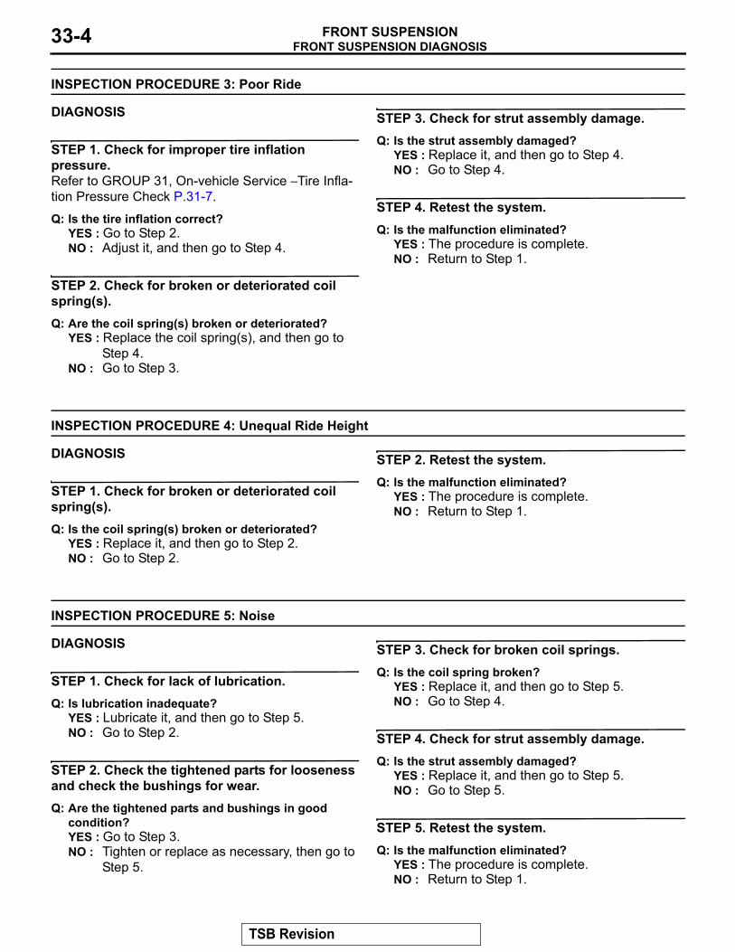
INSPECTION PROCEDURE 3: Poor Ride
DIAGNOSIS
STEP 1. Check for improper tire inflation pressure.Refer to GROUP 31, On-vehicle Service − Tire Infla-tion Pressure Check P.31-7.
Q: Is the tire inflation correct?YES : Go to Step 2.NO : Adjust it, and then go to Step 4.
STEP 2. Check for broken or deteriorated coil spring(s).Q: Are the coil spring(s) broken or deteriorated?
YES : Replace the coil spring(s), and then go to Step 4.
NO : Go to Step 3.
STEP 3. Check for strut assembly damage.Q: Is the strut assembly damaged?
YES : Replace it, and then go to Step 4.NO : Go to Step 4.
STEP 4. Retest the system.Q: Is the malfunction eliminated?
YES : The procedure is complete.NO : Return to Step 1.
INSPECTION PROCEDURE 4: Unequal Ride Height
DIAGNOSIS
STEP 1. Check for broken or deteriorated coil spring(s).Q: Is the coil spring(s) broken or deteriorated?
YES : Replace it, and then go to Step 2.NO : Go to Step 2.
STEP 2. Retest the system.Q: Is the malfunction eliminated?
YES : The procedure is complete.NO : Return to Step 1.
INSPECTION PROCEDURE 5: Noise
DIAGNOSIS
STEP 1. Check for lack of lubrication.Q: Is lubrication inadequate?
YES : Lubricate it, and then go to Step 5.NO : Go to Step 2.
STEP 2. Check the tightened parts for looseness and check the bushings for wear.Q: Are the tightened parts and bushings in good
condition?YES : Go to Step 3.NO : Tighten or replace as necessary, then go to
Step 5.
STEP 3. Check for broken coil springs.Q: Is the coil spring broken?
YES : Replace it, and then go to Step 5.NO : Go to Step 4.
STEP 4. Check for strut assembly damage.Q: Is the strut assembly damaged?
YES : Replace it, and then go to Step 5.NO : Go to Step 5.
STEP 5. Retest the system.Q: Is the malfunction eliminated?
YES : The procedure is complete.NO : Return to Step 1.
TSB Revision
SPECIAL TOOLSFRONT SUSPENSION 33-5
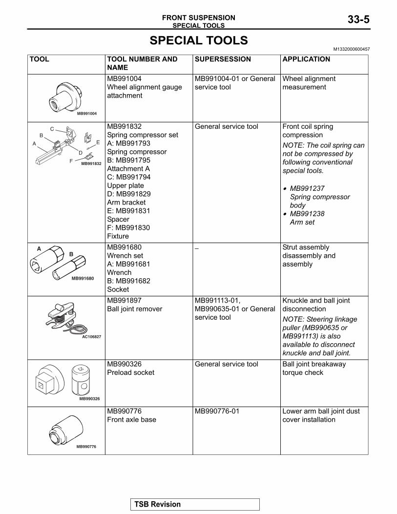
SPECIAL TOOLSM1332000600457
TOOL TOOL NUMBER AND NAME
SUPERSESSION APPLICATION
MB991004
MB991004Wheel alignment gauge attachment
MB991004-01 or General service tool
Wheel alignment measurement
MB991832
A
BC
D
E
F
MB991832Spring compressor setA: MB991793Spring compressorB: MB991795Attachment AC: MB991794Upper plateD: MB991829Arm bracketE: MB991831SpacerF: MB991830Fixture
General service tool Front coil spring compressionNOTE: The coil spring can not be compressed by following conventional special tools..• MB991237
Spring compressor body
• MB991238Arm set
MB991680
AB
MB991680Wrench setA: MB991681WrenchB: MB991682Socket
− Strut assembly disassembly and assembly
AC106827
MB991897Ball joint remover
MB991113-01, MB990635-01 or General service tool
Knuckle and ball joint disconnectionNOTE: Steering linkage puller (MB990635 or MB991113) is also available to disconnect knuckle and ball joint.
MB990326
MB990326Preload socket
General service tool Ball joint breakaway torque check
MB990776
MB990776Front axle base
MB990776-01 Lower arm ball joint dust cover installation
TSB Revision
ON-VEHICLE SERVICEFRONT SUSPENSION33-6
MB991963
ON-VEHICLE SERVICEFRONT WHEEL ALIGNMENT CHECK AND ADJUSTMENT
M1331000900778
Measure wheel alignment with alignment equipment on a level surface. The front suspension, steering system and tires should be serviced to normal condition before measuring wheel align-ment..
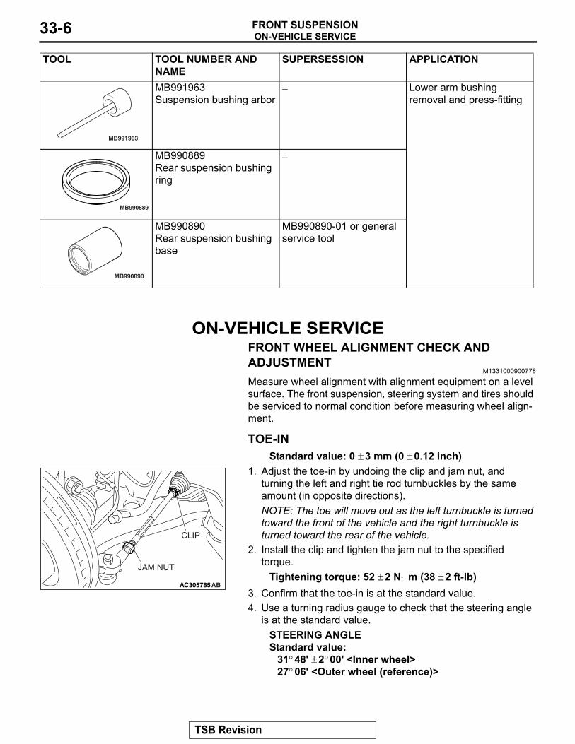
TOE-INStandard value: 0 ± 3 mm (0 ± 0.12 inch)
AC305785AB
JAM NUT
CLIP
1. Adjust the toe-in by undoing the clip and jam nut, and turning the left and right tie rod turnbuckles by the same amount (in opposite directions).NOTE: The toe will move out as the left turnbuckle is turned toward the front of the vehicle and the right turnbuckle is turned toward the rear of the vehicle.
2. Install the clip and tighten the jam nut to the specified torque.
Tightening torque: 52 ± 2 N⋅ m (38 ± 2 ft-lb)3. Confirm that the toe-in is at the standard value.4. Use a turning radius gauge to check that the steering angle
is at the standard value.STEERING ANGLEStandard value:
31° 48' ± 2° 00' <Inner wheel>27° 06' <Outer wheel (reference)>
.
MB991963Suspension bushing arbor
− Lower arm bushing removal and press-fitting
MB990889
MB990889Rear suspension bushing ring
−
MB990890
MB990890Rear suspension bushing base
MB990890-01 or general service tool
TOOL TOOL NUMBER AND NAME
SUPERSESSION APPLICATION
TSB Revision
ON-VEHICLE SERVICEFRONT SUSPENSION 33-7
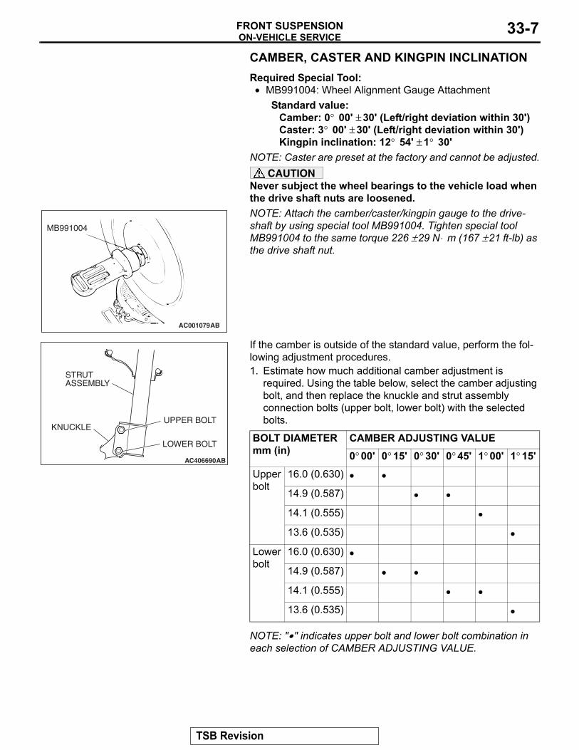
CAMBER, CASTER AND KINGPIN INCLINATIONRequired Special Tool:• MB991004: Wheel Alignment Gauge Attachment
Standard value:Camber: 0° 00' ± 30' (Left/right deviation within 30') Caster: 3° 00' ± 30' (Left/right deviation within 30') Kingpin inclination: 12° 54' ± 1° 30'
NOTE: Caster are preset at the factory and cannot be adjusted.CAUTION
Never subject the wheel bearings to the vehicle load when the drive shaft nuts are loosened.NOTE:
AC001079
MB991004
AB
Attach the camber/caster/kingpin gauge to the drive-shaft by using special tool MB991004. Tighten special tool MB991004 to the same torque 226 ± 29 N⋅ m (167 ± 21 ft-lb) as the drive shaft nut.
AC406690
STRUTASSEMBLY
LOWER BOLT
UPPER BOLTKNUCKLE
AB
If the camber is outside of the standard value, perform the fol-lowing adjustment procedures.1. Estimate how much additional camber adjustment is
required. Using the table below, select the camber adjusting bolt, and then replace the knuckle and strut assembly connection bolts (upper bolt, lower bolt) with the selected bolts.
BOLT DIAMETER mm (in)
CAMBER ADJUSTING VALUE0° 00' 0° 15' 0° 30' 0° 45' 1° 00' 1° 15'
Upper bolt
16.0 (0.630) • •
14.9 (0.587) • •
14.1 (0.555) •
13.6 (0.535) •
Lower bolt
16.0 (0.630) •
14.9 (0.587) • •
14.1 (0.555) • •
13.6 (0.535) •
NOTE: "•" indicates upper bolt and lower bolt combination in each selection of CAMBER ADJUSTING VALUE.
TSB Revision
ON-VEHICLE SERVICEFRONT SUSPENSION33-8
AC405911AB
A
A
HEAD MARK
IDENTIFICATIONPROJECTION
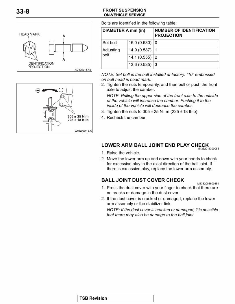
Bolts are identified in the following table:
DIAMETER A mm (in) NUMBER OF IDENTIFICATION PROJECTION
Set bolt 16.0 (0.630) 0
Adjusting bolt
14.9 (0.587) 1
14.1 (0.555) 2
13.6 (0.535) 3
NOTE: Set bolt is the bolt installed at factory. "10" embossed on bolt head is head mark.
AC406681
305 ± 25 N·m225 ± 18 ft-lb
AD
2. Tighten the nuts temporarily, and then pull or push the front axle to adjust the camber.NOTE: Pulling the upper side of the front axle to the outside of the vehicle will increase the camber. Pushing it to the inside of the vehicle will decrease the camber.
3. Tighten the nuts to 305 ± 25 N⋅ m (225 ± 18 ft-lb).4. Recheck the camber.
LOWER ARM BALL JOINT END PLAY CHECKM1332011300085
1. Raise the vehicle.2. Move the lower arm up and down with your hands to check
for excessive play in the axial direction of the ball joint. If there is excessive play, replace the lower arm assembly.
BALL JOINT DUST COVER CHECKM1332008600354
1. Press the dust cover with your finger to check that there are no cracks or damage in the dust cover.
2. If the dust cover is cracked or damaged, replace the lower arm assembly or the stabilizer link.NOTE: If the dust cover is cracked or damaged, it is possible that there may also be damage to the ball joint.
TSB Revision
STRUT ASSEMBLYFRONT SUSPENSION 33-9
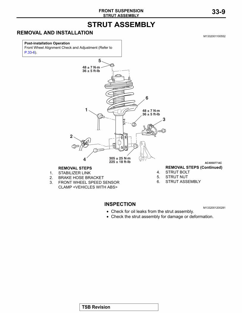
STRUT ASSEMBLYREMOVAL AND INSTALLATION
M1332001100552
Post-installation OperationFront Wheel Alignment Check and Adjustment (Refer to P.33-6).
AC405077
48 ± 7 N·m36 ± 5 ft-lb
1
2
3
4AC
305 ± 25 N·m225 ± 18 ft-lb
6
48 ± 7 N·m36 ± 5 ft-lb
5
REMOVAL STEPS 1. STABILIZER LINK2. BRAKE HOSE BRACKET3. FRONT WHEEL SPEED SENSOR
CLAMP <VEHICLES WITH ABS>
4. STRUT BOLT5. STRUT NUT6. STRUT ASSEMBLY
INSPECTIONM1332001200281
• Check for oil leaks from the strut assembly.• Check the strut assembly for damage or deformation.
REMOVAL STEPS (Continued)
TSB Revision
STRUT ASSEMBLYFRONT SUSPENSION33-10
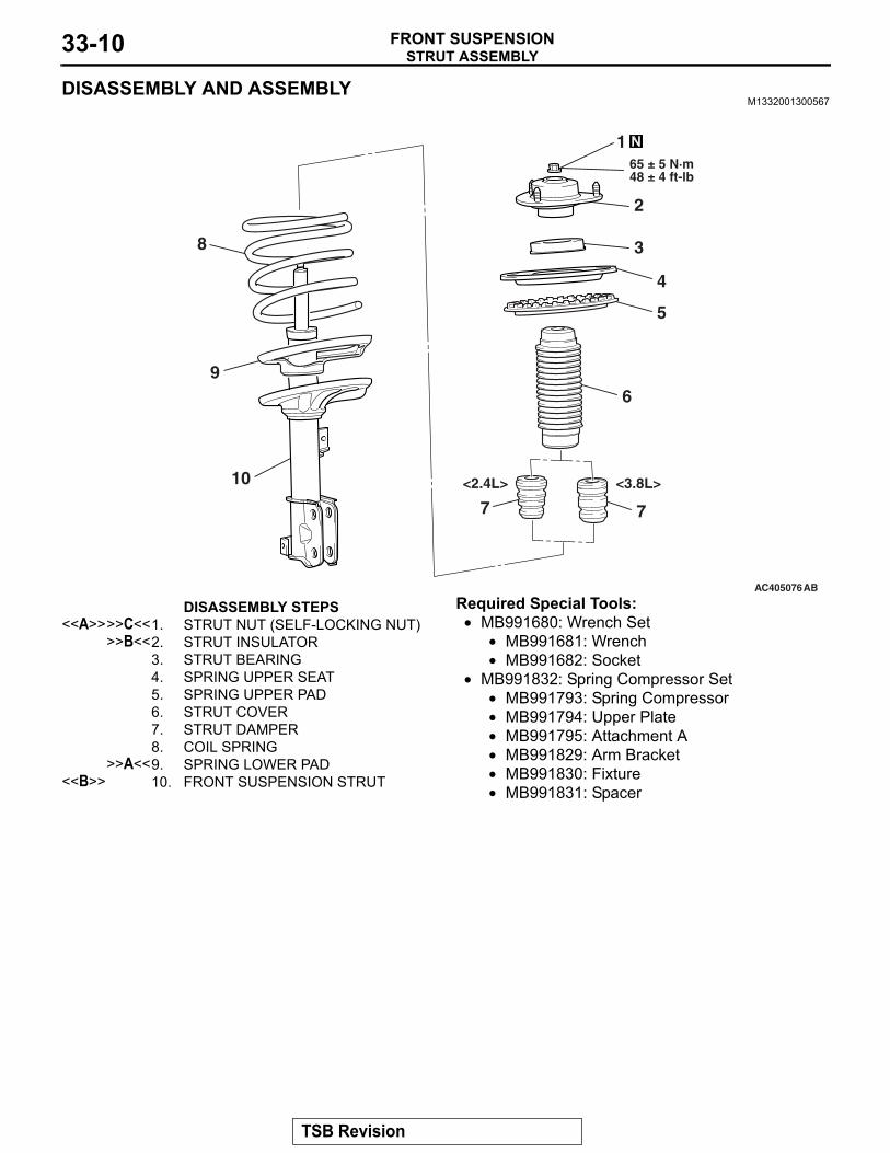
DISASSEMBLY AND ASSEMBLYM1332001300567
AC405076
7
<2.4L> <3.8L>
8
9
10
1
2
3
4
5
6
65 ± 5 N·m48 ± 4 ft-lb
AB
7
DISASSEMBLY STEPS <<A>>>>C<<1. STRUT NUT (SELF-LOCKING NUT)
>>B<<2. STRUT INSULATOR3. STRUT BEARING4. SPRING UPPER SEAT5. SPRING UPPER PAD6. STRUT COVER7. STRUT DAMPER8. COIL SPRING
>>A<<9. SPRING LOWER PAD<<B>> 10. FRONT SUSPENSION STRUT
Required Special Tools:• MB991680: Wrench Set
• MB991681: Wrench• MB991682: Socket
• MB991832: Spring Compressor Set• MB991793: Spring Compressor• MB991794: Upper Plate• MB991795: Attachment A• MB991829: Arm Bracket• MB991830: Fixture• MB991831: Spacer
TSB Revision
STRUT ASSEMBLYFRONT SUSPENSION 33-11
DISASSEMBLY SERVICE POINTS.
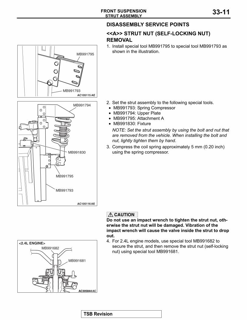
<<A>> STRUT NUT (SELF-LOCKING NUT) REMOVAL
AC105115 AE
MB991795
MB991793
1. Install special tool MB991795 to special tool MB991793 as shown in the illustration.
AC105116AE
MB991794
MB991830
MB991795
MB991793
2. Set the strut assembly to the following special tools.• MB991793: Spring Compressor• MB991794: Upper Plate• MB991795: Attachment A• MB991830: Fixture
NOTE: Set the strut assembly by using the bolt and nut that are removed from the vehicle. When installing the bolt and nut, lightly tighten them by hand.
3. Compress the coil spring approximately 5 mm (0.20 inch) using the spring compressor.
CAUTIONDo not use an impact wrench to tighten the strut nut, oth-erwise the strut nut will be damaged. Vibration of the impact wrench will cause the valve inside the strut to drop out.
AC302425
AC305844AC
MB991681
MB991682<2.4L ENGINE> 4. For 2.4L engine models, use special tool MB991682 to
secure the strut, and then remove the strut nut (self-locking nut) using special tool MB991681.
TSB Revision
STRUT ASSEMBLYFRONT SUSPENSION33-12
AC405831AB
MB991681
HEXAGON WRENCH
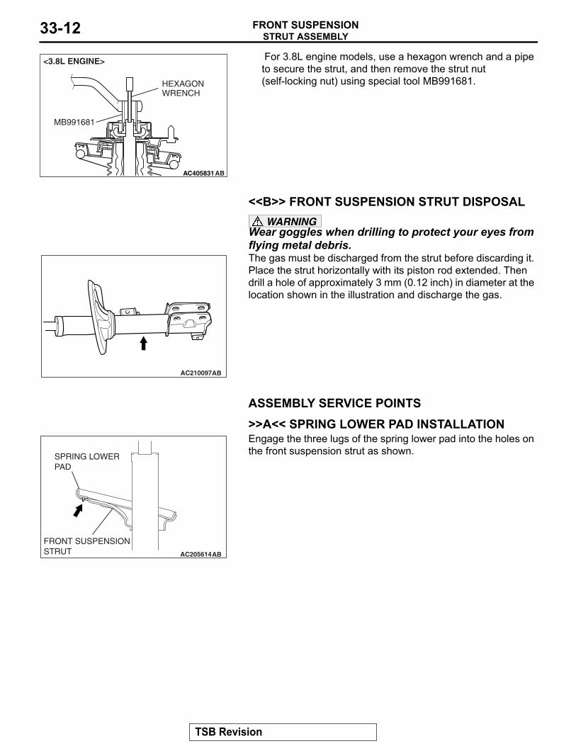
<3.8L ENGINE> For 3.8L engine models, use a hexagon wrench and a pipe to secure the strut, and then remove the strut nut (self-locking nut) using special tool MB991681.
.
<<B>> FRONT SUSPENSION STRUT DISPOSALWARNING
Wear goggles when drilling to protect your eyes from flying metal debris.
AC210097AB
The gas must be discharged from the strut before discarding it. Place the strut horizontally with its piston rod extended. Then drill a hole of approximately 3 mm (0.12 inch) in diameter at the location shown in the illustration and discharge the gas.
ASSEMBLY SERVICE POINTS.
>>A<< SPRING LOWER PAD INSTALLATION
AC205614AB
SPRING LOWER PAD
FRONT SUSPENSION STRUT
Engage the three lugs of the spring lower pad into the holes on the front suspension strut as shown.
.
TSB Revision
STRUT ASSEMBLYFRONT SUSPENSION 33-13
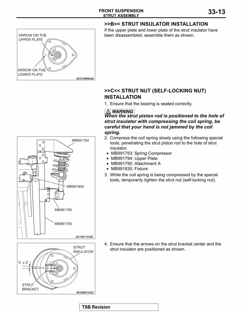
>>B<< STRUT INSULATOR INSTALLATION
AC210098AB
ARROW ON THE UPPER PLATE
ARROW ON THE LOWER PLATE
If the upper plate and lower plate of the strut insulator have been disassembled, assemble them as shown.
.
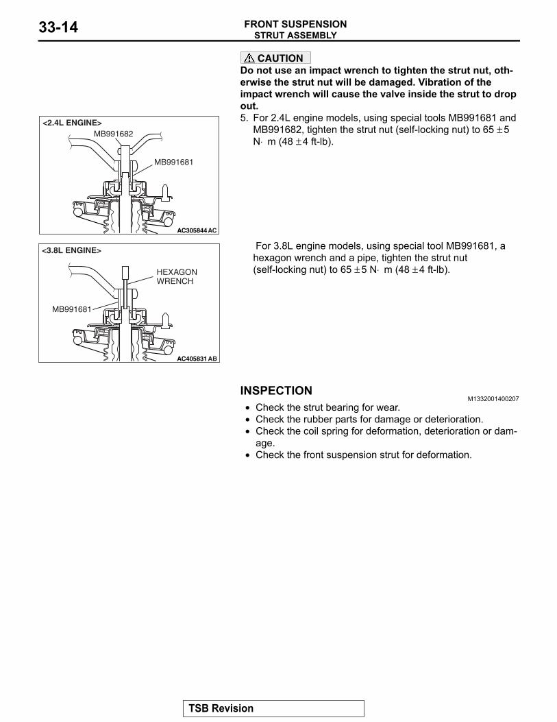
>>C<< STRUT NUT (SELF-LOCKING NUT) INSTALLATION1. Ensure that the bearing is seated correctly.
WARNINGWhen the strut piston rod is positioned to the hole of strut insulator with compressing the coil spring, be careful that your hand is not jammed by the coil spring.
AC105116AE
MB991794
MB991830
MB991795
MB991793
2. Compress the coil spring slowly using the following special tools, penetrating the strut piston rod to the hole of strut insulator.
• MB991793: Spring Compressor• MB991794: Upper Plate• MB991795: Attachment A• MB991830: Fixture
3. While the coil spring is being compressed by the special tools, temporarily tighten the strut nut (self-locking nut).
AC205613
STRUT INSULATOR
AC
0˚ ± 2˚
STRUT BRACKET
4. Ensure that the arrows on the strut bracket center and the strut insulator are positioned as shown.
TSB Revision
STRUT ASSEMBLYFRONT SUSPENSION33-14
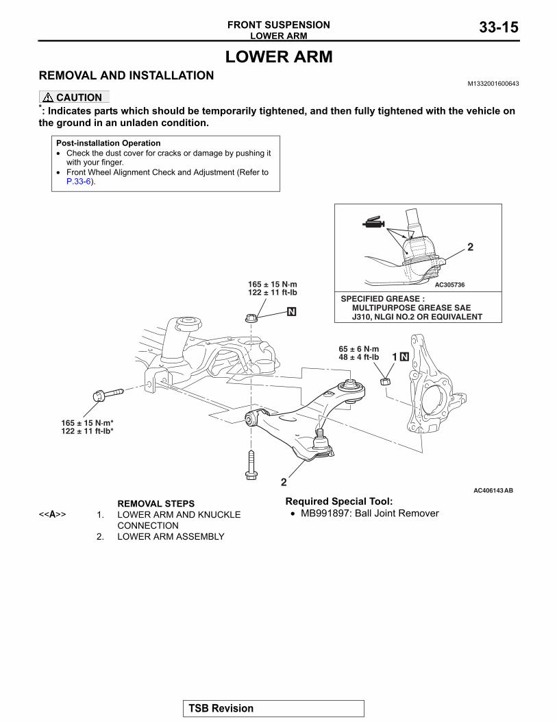
CAUTIONDo not use an impact wrench to tighten the strut nut, oth-erwise the strut nut will be damaged. Vibration of the impact wrench will cause the valve inside the strut to drop out.
AC302425
AC305844AC
MB991681
MB991682<2.4L ENGINE> 5. For 2.4L engine models, using special tools MB991681 and
MB991682, tighten the strut nut (self-locking nut) to 65 ± 5 N⋅ m (48 ± 4 ft-lb).
AC405831AB
MB991681
HEXAGON WRENCH
<3.8L ENGINE> For 3.8L engine models, using special tool MB991681, a hexagon wrench and a pipe, tighten the strut nut (self-locking nut) to 65 ± 5 N⋅ m (48 ± 4 ft-lb).
INSPECTIONM1332001400207
• Check the strut bearing for wear.• Check the rubber parts for damage or deterioration.• Check the coil spring for deformation, deterioration or dam-
age.• Check the front suspension strut for deformation.
TSB Revision
LOWER ARMFRONT SUSPENSION 33-15
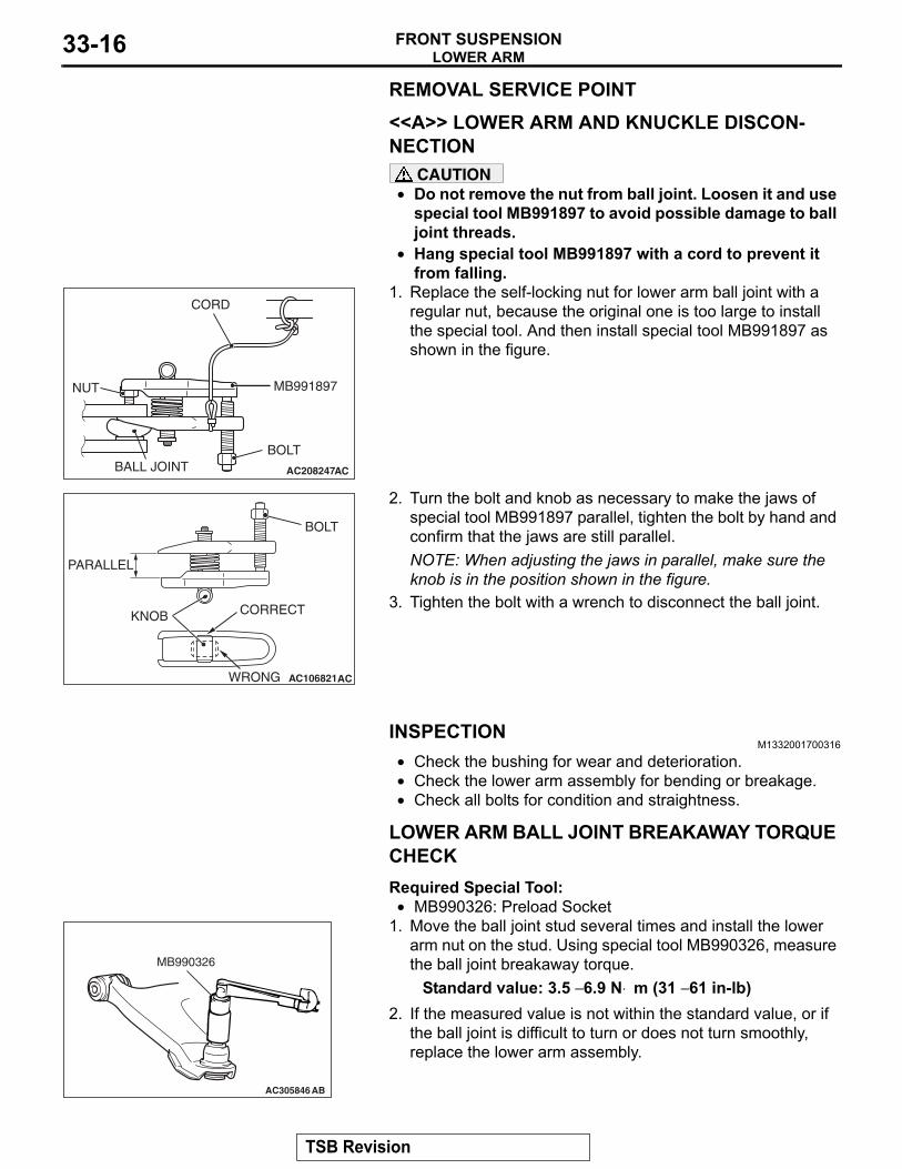
LOWER ARMREMOVAL AND INSTALLATION
M1332001600643
CAUTION*: Indicates parts which should be temporarily tightened, and then fully tightened with the vehicle on the ground in an unladen condition.
Post-installation Operation• Check the dust cover for cracks or damage by pushing it
with your finger.• Front Wheel Alignment Check and Adjustment (Refer to
P.33-6).
AC406143
AC305736
AB
1
2
N
165 ± 15 N·m*122 ± 11 ft-lb*
65 ± 6 N·m48 ± 4 ft-lb
SPECIFIED GREASE : MULTIPURPOSE GREASE SAE J310, NLGI NO.2 OR EQUIVALENT
165 ± 15 N·m122 ± 11 ft-lb
N
2
REMOVAL STEPS <<A>> 1. LOWER ARM AND KNUCKLE
CONNECTION2. LOWER ARM ASSEMBLY
Required Special Tool:• MB991897: Ball Joint Remover
TSB Revision
LOWER ARMFRONT SUSPENSION33-16
REMOVAL SERVICE POINT.
<<A>> LOWER ARM AND KNUCKLE DISCON-NECTION
CAUTION• Do not remove the nut from ball joint. Loosen it and use
special tool MB991897 to avoid possible damage to ball joint threads.
•
AC208247AC
CORD
BOLT
MB991897NUT
BALL JOINT
Hang special tool MB991897 with a cord to prevent it from falling.
1. Replace the self-locking nut for lower arm ball joint with a regular nut, because the original one is too large to install the special tool. And then install special tool MB991897 as shown in the figure.
AC106821
KNOB
PARALLEL
BOLT
CORRECT
WRONG AC
2. Turn the bolt and knob as necessary to make the jaws of special tool MB991897 parallel, tighten the bolt by hand and confirm that the jaws are still parallel.NOTE: When adjusting the jaws in parallel, make sure the knob is in the position shown in the figure.
3. Tighten the bolt with a wrench to disconnect the ball joint.
INSPECTIONM1332001700316
• Check the bushing for wear and deterioration.• Check the lower arm assembly for bending or breakage.• Check all bolts for condition and straightness.
.
LOWER ARM BALL JOINT BREAKAWAY TORQUE CHECKRequired Special Tool:•
AC305846 AB
MB990326
MB990326: Preload Socket1. Move the ball joint stud several times and install the lower
arm nut on the stud. Using special tool MB990326, measure the ball joint breakaway torque.
Standard value: 3.5 − 6.9 N⋅ m (31 − 61 in-lb)2. If the measured value is not within the standard value, or if
the ball joint is difficult to turn or does not turn smoothly, replace the lower arm assembly.
.
TSB Revision
LOWER ARMFRONT SUSPENSION 33-17
LOWER ARM BALL JOINT DUST COVER CHECK1. Check the dust cover for cracks or damage by pushing it
with your finger.2. If the dust cover is cracked or damaged, replace the lower
arm assembly.NOTE: Cracks or damage to the dust cover may cause damage to the ball joint. When it is damaged during service work, replace the dust cover.
LOWER ARM BALL JOINT DUST COVER REPLACEMENT
M1332008200408
Required Special Tool:• MB990776: Front Axle Base
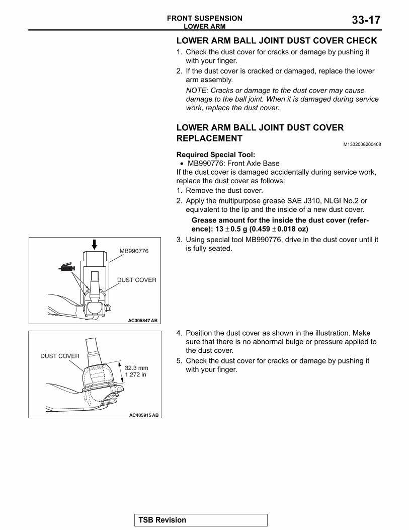
If the dust cover is damaged accidentally during service work, replace the dust cover as follows:1. Remove the dust cover.2. Apply the multipurpose grease SAE J310, NLGI No.2 or
equivalent to the lip and the inside of a new dust cover.Grease amount for the inside the dust cover (refer-ence): 13 ± 0.5 g (0.459 ± 0.018 oz)
AC305847 AB
MB990776
DUST COVER
3. Using special tool MB990776, drive in the dust cover until it is fully seated.
AC405915AB
32.3 mm1.272 in
DUST COVER
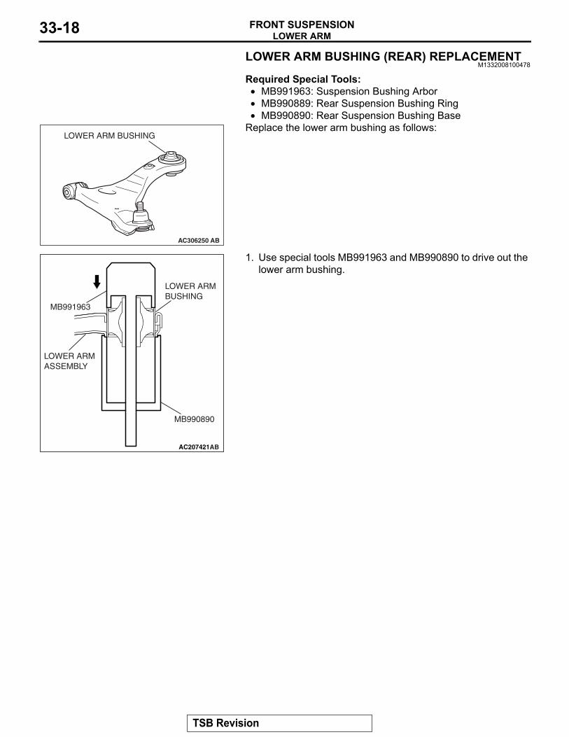
4. Position the dust cover as shown in the illustration. Make sure that there is no abnormal bulge or pressure applied to the dust cover.
5. Check the dust cover for cracks or damage by pushing it with your finger.
TSB Revision
LOWER ARMFRONT SUSPENSION33-18
LOWER ARM BUSHING (REAR) REPLACEMENTM1332008100478
Required Special Tools:• MB991963: Suspension Bushing Arbor• MB990889: Rear Suspension Bushing Ring•
AC306250 AB
LOWER ARM BUSHING
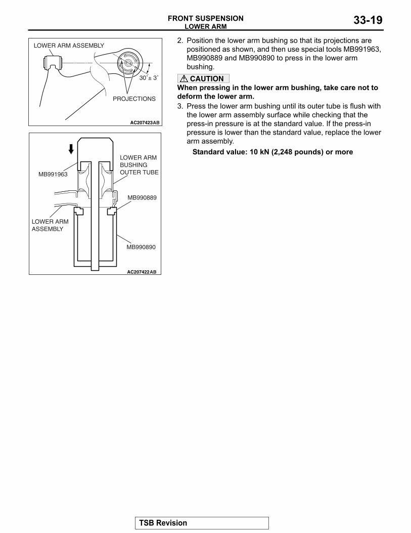
MB990890: Rear Suspension Bushing BaseReplace the lower arm bushing as follows:
AC207421AB
MB991963
MB990890
LOWER ARMASSEMBLY
LOWER ARM BUSHING
1. Use special tools MB991963 and MB990890 to drive out the lower arm bushing.
TSB Revision
LOWER ARMFRONT SUSPENSION 33-19
AC207423AB
PROJECTIONS
30˚± 3˚
LOWER ARM ASSEMBLY
AC207422AB
MB991963
MB990890
LOWER ARMASSEMBLY
MB990889
LOWER ARM BUSHINGOUTER TUBE
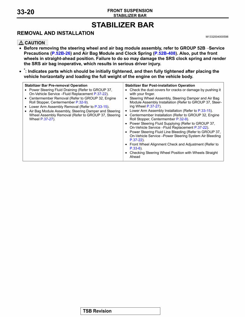
2. Position the lower arm bushing so that its projections are positioned as shown, and then use special tools MB991963, MB990889 and MB990890 to press in the lower arm bushing.CAUTION
When pressing in the lower arm bushing, take care not to deform the lower arm.3. Press the lower arm bushing until its outer tube is flush with
the lower arm assembly surface while checking that the press-in pressure is at the standard value. If the press-in pressure is lower than the standard value, replace the lower arm assembly.
Standard value: 10 kN (2,248 pounds) or more
TSB Revision
STABILIZER BARFRONT SUSPENSION33-20
STABILIZER BARREMOVAL AND INSTALLATION
M1332004000598
CAUTION• Before removing the steering wheel and air bag module assembly, refer to GROUP 52B − Service
Precautions (P.52B-26) and Air Bag Module and Clock Spring (P.52B-408). Also, put the front wheels in straight-ahead position. Failure to do so may damage the SRS clock spring and render the SRS air bag inoperative, which results in serious driver injury.
•
Stabilizer Bar Pre-removal Operation• Power Steering Fluid Draining (Refer to GROUP 37,
On-Vehicle Service − Fluid Replacement P.37-22).• Centermember Removal (Refer to GROUP 32, Engine
Roll Stopper, Centermember P.32-9).• Lower Arm Assembly Removal (Refer to P.33-15).• Air Bag Module Assembly, Steering Damper and Steering
Wheel Assembly Removal (Refer to GROUP 37, Steering Wheel P.37-27).
Stabilizer Bar Post-installation Operation• Check the dust covers for cracks or damage by pushing it
with your finger.• Steering Wheel Assembly, Steering Damper and Air Bag
Module Assembly Installation (Refer to GROUP 37, Steer-ing Wheel P.37-27).
• Lower Arm Assembly Installation (Refer to P.33-15).• Centermember Installation (Refer to GROUP 32, Engine
Roll Stopper, Centermember P.32-9).• Power Steering Fluid Supplying (Refer to GROUP 37,
On-Vehicle Service − Fluid Replacement P.37-22).• Power Steering Fluid Line Bleeding (Refer to GROUP 37,
On-Vehicle Service − Power Steering System Air Bleeding P.37-22).
• Front Wheel Alignment Check and Adjustment (Refer to P.33-6).
• Checking Steering Wheel Position with Wheels Straight Ahead
*: Indicates parts which should be initially tightened, and then fully tightened after placing the vehicle horizontally and loading the full weight of the engine on the vehicle body.
TSB Revision
STABILIZER BARFRONT SUSPENSION 33-21
AC405083AB
48 ± 7 N·m36 ± 5 ft-lb
180 ± 20 N·m133 ± 14 ft-lb
58 ± 7 N·m*43 ± 5 ft-lb*
83 ± 12 N·m61 ± 9 ft-lb
18 ± 2 N·m13 ± 2 ft-lb
7
1
3
4
10
9
29 ± 4 N·m21 ± 3 ft-lb
8
58 ± 7 N·m43 ± 5 ft-lb
48 ± 7 N·m36 ± 5 ft-lb
12 ± 2 N·m102 ± 22 in-lb
12 ± 2 N·m102 ± 22 in-lb
15 ± 3 N·m11 ± 2 ft-lb
12 ± 2 N·m102 ± 22 in-lb
5 6
12
13
1614
15
11
2
12 ± 2 N·m102 ± 22 in-lb
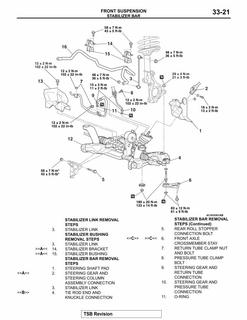
STABILIZER LINK REMOVAL STEPS
3. STABILIZER LINKSTABILIZER BUSHING REMOVAL STEPS
3. STABILIZER LINK>>A<< 14. STABILIZER BRACKET>>A<< 15. STABILIZER BUSHING
STABILIZER BAR REMOVAL STEPS
1. STEERING SHAFT PAD<<A>> 2. STEERING GEAR AND
STEERING COLUMN ASSEMBLY CONNECTION
3. STABILIZER LINK<<B>> 4. TIE ROD END AND
KNUCKLE CONNECTION
5. REAR ROLL STOPPER CONNECTION BOLT
<<C>> >>C<< 6. FRONT AXLE CROSSMEMBER STAY
7. RETURN TUBE CLAMP NUT AND BOLT
8. PRESSURE TUBE CLAMP BOLT
9. STEERING GEAR AND RETURN TUBE CONNECTION
10. STEERING GEAR AND PRESSURE TUBE CONNECTION
11. O-RING
STABILIZER BAR REMOVAL STEPS (Continued)
TSB Revision
STABILIZER BARFRONT SUSPENSION33-22
Required Special Tool:• MB991897: Ball Joint Remover
REMOVAL SERVICE POINTS.
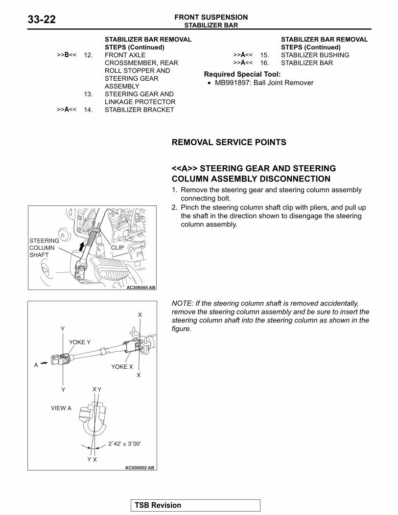
<<A>> STEERING GEAR AND STEERING COLUMN ASSEMBLY DISCONNECTION1. Remove the steering gear and steering column assembly
connecting bolt.
AC306565 AB
CLIPSTEERINGCOLUMNSHAFT
2. Pinch the steering column shaft clip with pliers, and pull up the shaft in the direction shown to disengage the steering column assembly.
NOTE:
AC500002 AB
X
X
Y
Y
X
X
Y
Y
YOKE Y
VIEW A
2˚42' ± 3˚00'
YOKE XA
If the steering column shaft is removed accidentally, remove the steering column assembly and be sure to insert the steering column shaft into the steering column as shown in the figure.
.
>>B<< 12. FRONT AXLE CROSSMEMBER, REAR ROLL STOPPER AND STEERING GEAR ASSEMBLY
13. STEERING GEAR AND LINKAGE PROTECTOR
>>A<< 14. STABILIZER BRACKET
STABILIZER BAR REMOVAL STEPS (Continued)
>>A<< 15. STABILIZER BUSHING>>A<< 16. STABILIZER BAR
STABILIZER BAR REMOVAL STEPS (Continued)
TSB Revision
STABILIZER BARFRONT SUSPENSION 33-23
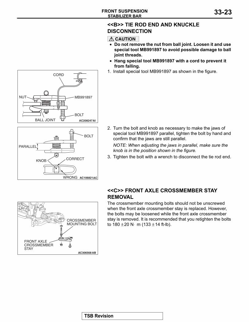
<<B>> TIE ROD END AND KNUCKLE DISCONNECTION
CAUTION• Do not remove the nut from ball joint. Loosen it and use
special tool MB991897 to avoid possible damage to ball joint threads.
•
AC208247AI
CORD
BOLT
MB991897NUT
BALL JOINT
Hang special tool MB991897 with a cord to prevent it from falling.
1. Install special tool MB991897 as shown in the figure.
AC106821
KNOB
PARALLEL
BOLT
CORRECT
WRONG AC
2. Turn the bolt and knob as necessary to make the jaws of special tool MB991897 parallel, tighten the bolt by hand and confirm that the jaws are still parallel.NOTE: When adjusting the jaws in parallel, make sure the knob is in the position shown in the figure.
3. Tighten the bolt with a wrench to disconnect the tie rod end.
.
<<C>> FRONT AXLE CROSSMEMBER STAY REMOVAL
AC306568 AB
FRONT AXLE CROSSMEMBER STAY
CROSSMEMBER MOUNTING BOLT
The crossmember mounting bolts should not be unscrewed when the front axle crossmember stay is replaced. However, the bolts may be loosened while the front axle crossmember stay is removed. It is recommended that you retighten the bolts to 180 ± 20 N⋅ m (133 ± 14 ft-lb).
TSB Revision
STABILIZER BARFRONT SUSPENSION33-24
INSTALLATION SERVICE POINTS.
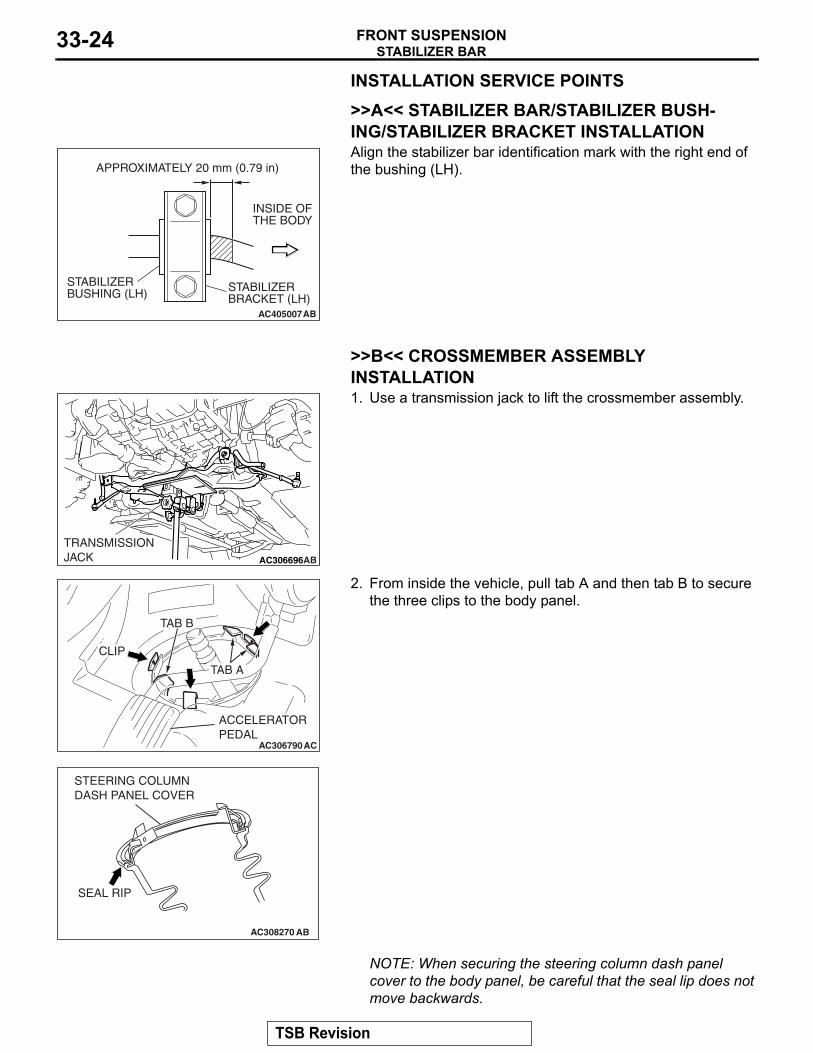
>>A<< STABILIZER BAR/STABILIZER BUSH-ING/STABILIZER BRACKET INSTALLATION
AC405007AB
APPROXIMATELY 20 mm (0.79 in)
INSIDE OFTHE BODY
STABILIZER BRACKET (LH)
STABILIZER BUSHING (LH)
Align the stabilizer bar identification mark with the right end of the bushing (LH).
.
>>B<< CROSSMEMBER ASSEMBLY INSTALLATION
AC206593
AC306696
TRANSMISSIONJACK AB
1. Use a transmission jack to lift the crossmember assembly.
AC306790AC
ACCELERATOR PEDAL
CLIP
TAB A
TAB B
2. From inside the vehicle, pull tab A and then tab B to secure the three clips to the body panel.
AC308270 AB
SEAL RIP
STEERING COLUMN DASH PANEL COVER
NOTE: When securing the steering column dash panel cover to the body panel, be careful that the seal lip does not move backwards.
TSB Revision
STABILIZER BARFRONT SUSPENSION 33-25
3. Check that it has been secured by pressing down the tip of the clips by your finger. Also check that the steering column dash panel cover is installed securely to the steering gear.
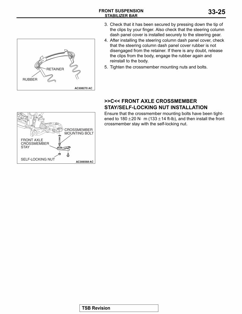
AC308270 AC
RUBBER
RETAINER
4. After installing the steering column dash panel cover, check that the steering column dash panel cover rubber is not disengaged from the retainer. If there is any doubt, release the clips from the body, engage the rubber again and reinstall to the body.
5. Tighten the crossmember mounting nuts and bolts.
.
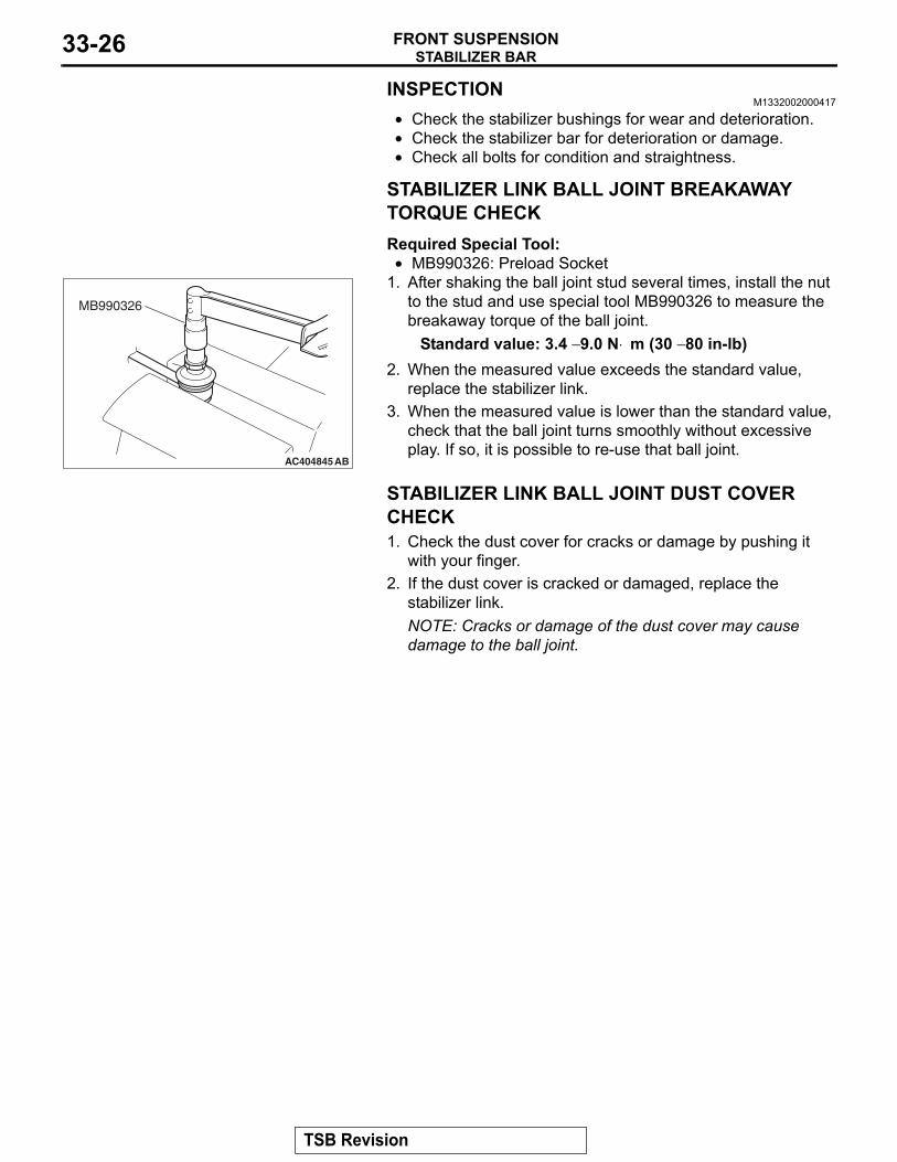
>>C<< FRONT AXLE CROSSMEMBER STAY/SELF-LOCKING NUT INSTALLATION
AC306568 AC
FRONT AXLE CROSSMEMBER STAY
CROSSMEMBER MOUNTING BOLT
SELF-LOCKING NUT
Ensure that the crossmember mounting bolts have been tight-ened to 180 ± 20 N⋅ m (133 ± 14 ft-lb), and then install the front crossmember stay with the self-locking nut.
TSB Revision
STABILIZER BARFRONT SUSPENSION33-26
INSPECTIONM1332002000417
• Check the stabilizer bushings for wear and deterioration.• Check the stabilizer bar for deterioration or damage.• Check all bolts for condition and straightness.
.
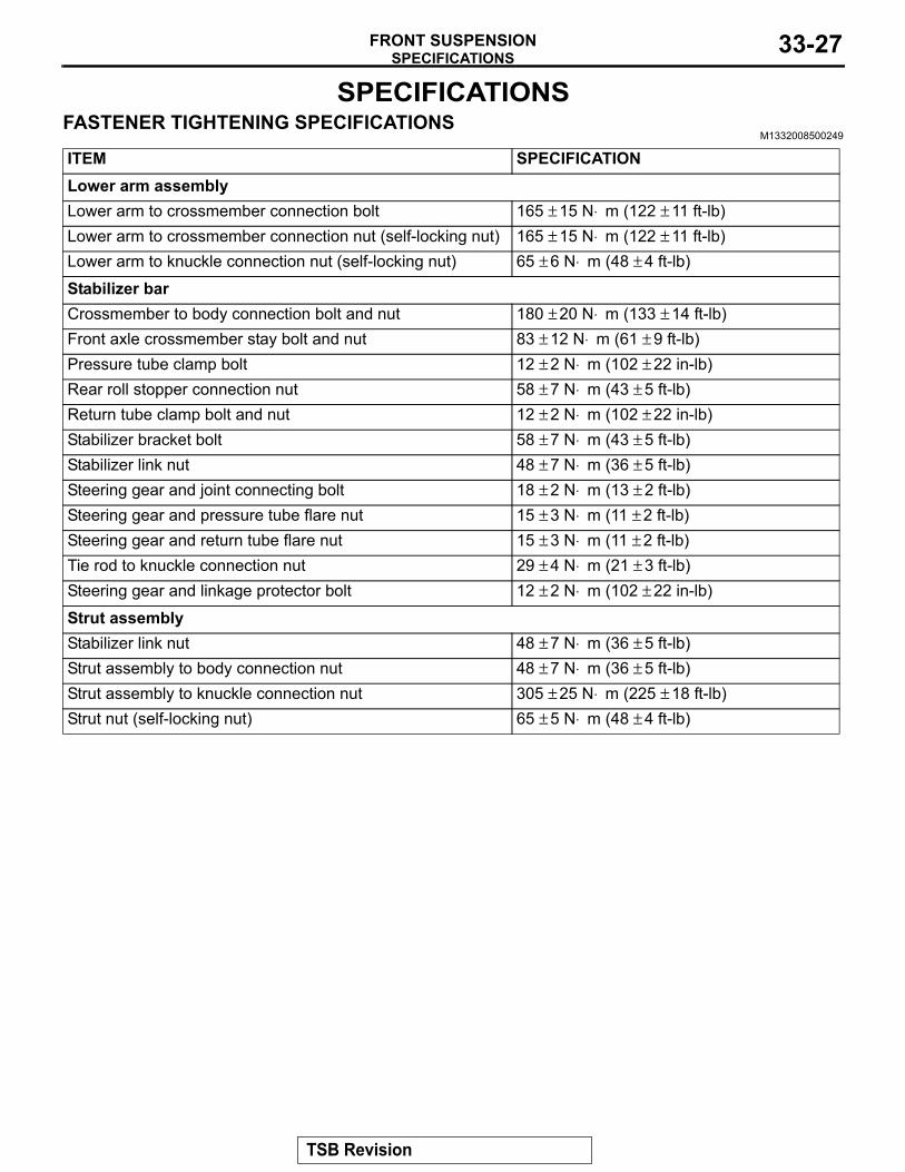
STABILIZER LINK BALL JOINT BREAKAWAY TORQUE CHECKRequired Special Tool:•
AC404845
MB990326
AB
MB990326: Preload Socket1. After shaking the ball joint stud several times, install the nut
to the stud and use special tool MB990326 to measure the breakaway torque of the ball joint.
Standard value: 3.4 − 9.0 N⋅ m (30 − 80 in-lb)2. When the measured value exceeds the standard value,
replace the stabilizer link.3. When the measured value is lower than the standard value,
check that the ball joint turns smoothly without excessive play. If so, it is possible to re-use that ball joint.
.
STABILIZER LINK BALL JOINT DUST COVER CHECK1. Check the dust cover for cracks or damage by pushing it
with your finger.2. If the dust cover is cracked or damaged, replace the
stabilizer link.NOTE: Cracks or damage of the dust cover may cause damage to the ball joint.
TSB Revision
SPECIFICATIONSFRONT SUSPENSION 33-27
SPECIFICATIONSFASTENER TIGHTENING SPECIFICATIONS
M1332008500249
ITEM SPECIFICATIONLower arm assemblyLower arm to crossmember connection bolt 165 ± 15 N⋅ m (122 ± 11 ft-lb)Lower arm to crossmember connection nut (self-locking nut) 165 ± 15 N⋅ m (122 ± 11 ft-lb)Lower arm to knuckle connection nut (self-locking nut) 65 ± 6 N⋅ m (48 ± 4 ft-lb)
Stabilizer barCrossmember to body connection bolt and nut 180 ± 20 N⋅ m (133 ± 14 ft-lb)Front axle crossmember stay bolt and nut 83 ± 12 N⋅ m (61 ± 9 ft-lb)Pressure tube clamp bolt 12 ± 2 N⋅ m (102 ± 22 in-lb)Rear roll stopper connection nut 58 ± 7 N⋅ m (43 ± 5 ft-lb)Return tube clamp bolt and nut 12 ± 2 N⋅ m (102 ± 22 in-lb)Stabilizer bracket bolt 58 ± 7 N⋅ m (43 ± 5 ft-lb)Stabilizer link nut 48 ± 7 N⋅ m (36 ± 5 ft-lb)Steering gear and joint connecting bolt 18 ± 2 N⋅ m (13 ± 2 ft-lb)Steering gear and pressure tube flare nut 15 ± 3 N⋅ m (11 ± 2 ft-lb)Steering gear and return tube flare nut 15 ± 3 N⋅ m (11 ± 2 ft-lb)Tie rod to knuckle connection nut 29 ± 4 N⋅ m (21 ± 3 ft-lb)Steering gear and linkage protector bolt 12 ± 2 N⋅ m (102 ± 22 in-lb)
Strut assemblyStabilizer link nut 48 ± 7 N⋅ m (36 ± 5 ft-lb)Strut assembly to body connection nut 48 ± 7 N⋅ m (36 ± 5 ft-lb)Strut assembly to knuckle connection nut 305 ± 25 N⋅ m (225 ± 18 ft-lb)Strut nut (self-locking nut) 65 ± 5 N⋅ m (48 ± 4 ft-lb)
TSB Revision
SPECIFICATIONSFRONT SUSPENSION33-28
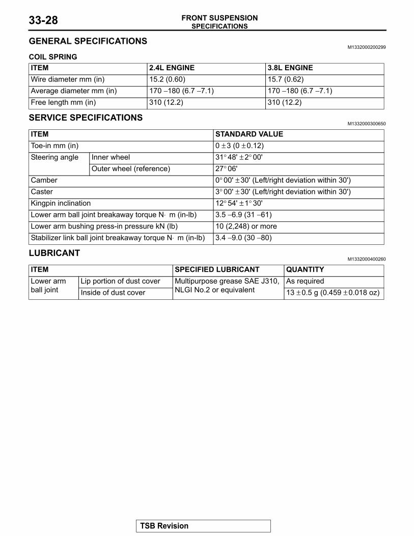
GENERAL SPECIFICATIONSM1332000200299
COIL SPRINGITEM 2.4L ENGINE 3.8L ENGINEWire diameter mm (in) 15.2 (0.60) 15.7 (0.62)Average diameter mm (in) 170 − 180 (6.7 − 7.1) 170 − 180 (6.7 − 7.1)Free length mm (in) 310 (12.2) 310 (12.2)
SERVICE SPECIFICATIONSM1332000300650
ITEM STANDARD VALUEToe-in mm (in) 0 ± 3 (0 ± 0.12)Steering angle Inner wheel 31° 48' ± 2° 00'
Outer wheel (reference) 27° 06'Camber 0° 00' ± 30' (Left/right deviation within 30')Caster 3° 00' ± 30' (Left/right deviation within 30')Kingpin inclination 12° 54' ± 1° 30'Lower arm ball joint breakaway torque N⋅ m (in-lb) 3.5 − 6.9 (31 − 61)Lower arm bushing press-in pressure kN (lb) 10 (2,248) or moreStabilizer link ball joint breakaway torque N⋅ m (in-lb) 3.4 − 9.0 (30 − 80)
LUBRICANTM1332000400260
ITEM SPECIFIED LUBRICANT QUANTITYLower arm ball joint
Lip portion of dust cover Multipurpose grease SAE J310, NLGI No.2 or equivalent
As requiredInside of dust cover 13 ± 0.5 g (0.459 ± 0.018 oz)
TSB Revision