geotechnical report highway reconstruction route … · highway program geotechnical report highway...
TRANSCRIPT
Maine Department of Transportation Highway Program
GEOTECHNICAL REPORT Highway Reconstruction
Route 236, South Berwick, Maine
Prepared by: Karen Gross
Geotechnical Design Engineer
York County Soils Report No. 2012-132
WIN 17852.00
Fed. Project STP-1785(200)x September 14, 2012
Map Scale 1:24000
The Maine Department of Transportation provides this publication for information only. Reliance upon this information is at user risk. It is subject to revisionand may be incomplete depending upon changing conditions. The Department assumes no liability if injuries or damages result from this information. Thismap is not intended to support emergency dispatch. Road names used on this map may not match official road names.
The Maine Department of Transportation provides this publication for information only. Reliance upon this information is at user risk. It is subject to revision and may be incomplete depending upon changingconditions. The Department assumes no liability if injuries or damages result from this information. This map is not intended to support emergency dispatch. Road names used on this map may not match officialroad names.
Highway Program
Brad Foley, Program Manager
Rich Crawford & Heath Cowan, Assistant Program Managers Phone: 624-3480 Fax: 624-3481
Memorandum
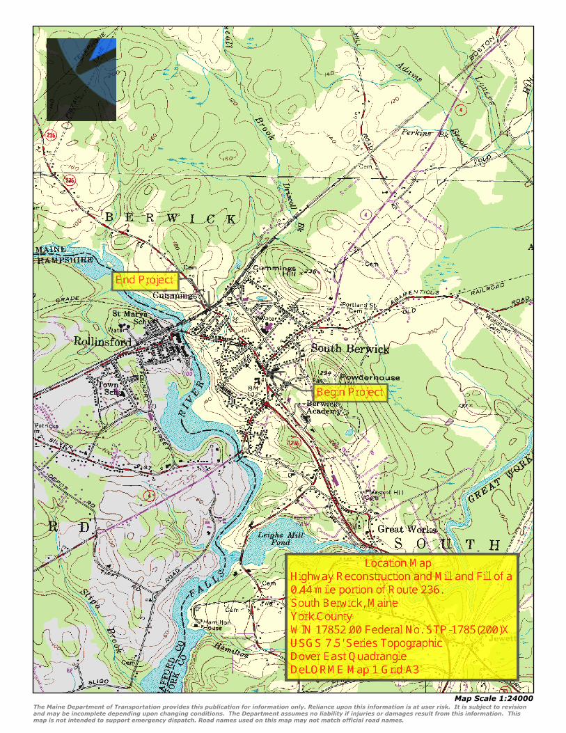
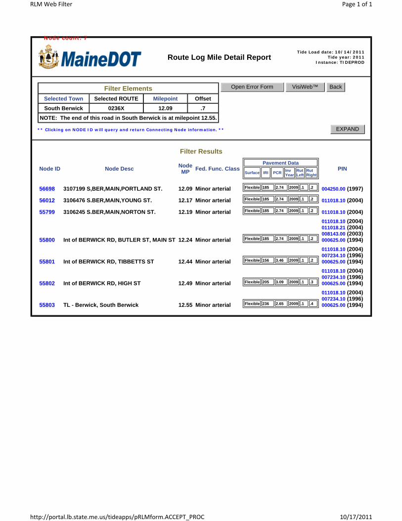
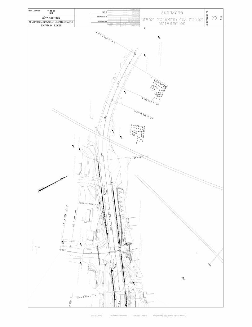
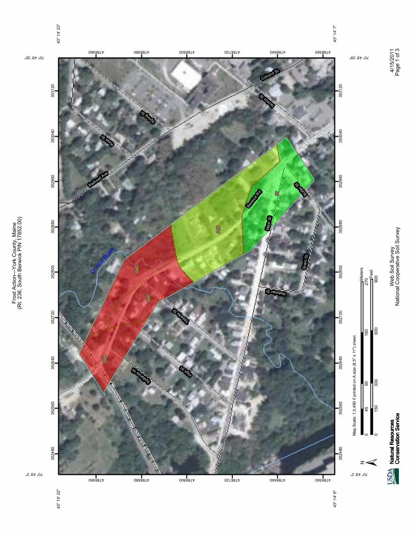
To: Sarah LeBlanc From: Karen Gross Date: 9/10/2012 Subject: So. Berwick, PIN 17852.00 Soils Report No. 2012-132 I have completed the subsurface investigations for the reconstruction of Route 236 in South Berwick. The following is a summary of the existing conditions, subsurface investigations, and my recommendations for the pavement structure design. Project Background MaineDOT proposes to reconstruct and overlay a section of Route 236 in the town of South Berwick. This section of Route 236 is classified as a minor arterial. The reconstruction project begins at the intersection with Main Street (RLM 12.24) and continues 0.29 miles to the north to the Pan Am Railroad tracks (RLM 12.53). The scope of work for the reconstruction section will include drainage improvements, sidewalks, curbing, and a new pavement structure. The mill and overlay section begins at the intersection with Portland Street (RLM 12.09) and extends 0.15 miles northerly to the intersection with Main Street (RLM 12.24) and the start of the reconstruction project. This preliminary report will focus on the existing types of pavement structure materials and how it was constructed, subgrade types and strengths, existing surface and subsurface drainage conditions, and frost considerations in the reconstruction section. Existing Pavement Assessment The existing roadway consists of two 11-foot travel lanes and variable width gravel shoulders. The current pavement distresses are considered to be low to moderate in severity, however there are a few locations where pavement distress can be considered severe (wide cracks). The primary distresses included rutting of the outer 1/3 of the travel lanes (structural distress), longitudinal cracking (structural and functional distress), block cracking (functional distress), and transverse cracking (functional distress). The cause of pavement distress is predominately due to frost action (heaving), poor pavement structure drainage, and lack of paved shoulders. Ditching is non-existent or shallow along most of the project. There also appears to be storm water erosion of the gravel shoulders in some locations. In addition to saturating the subbase and subgrade, water running in the gravel shoulder can cause undermining of the gravel underneath the asphalt surface course and the subsequent loss of support when traffic loads are applied. This shows up as rutting in the right wheel path.
Highway Program
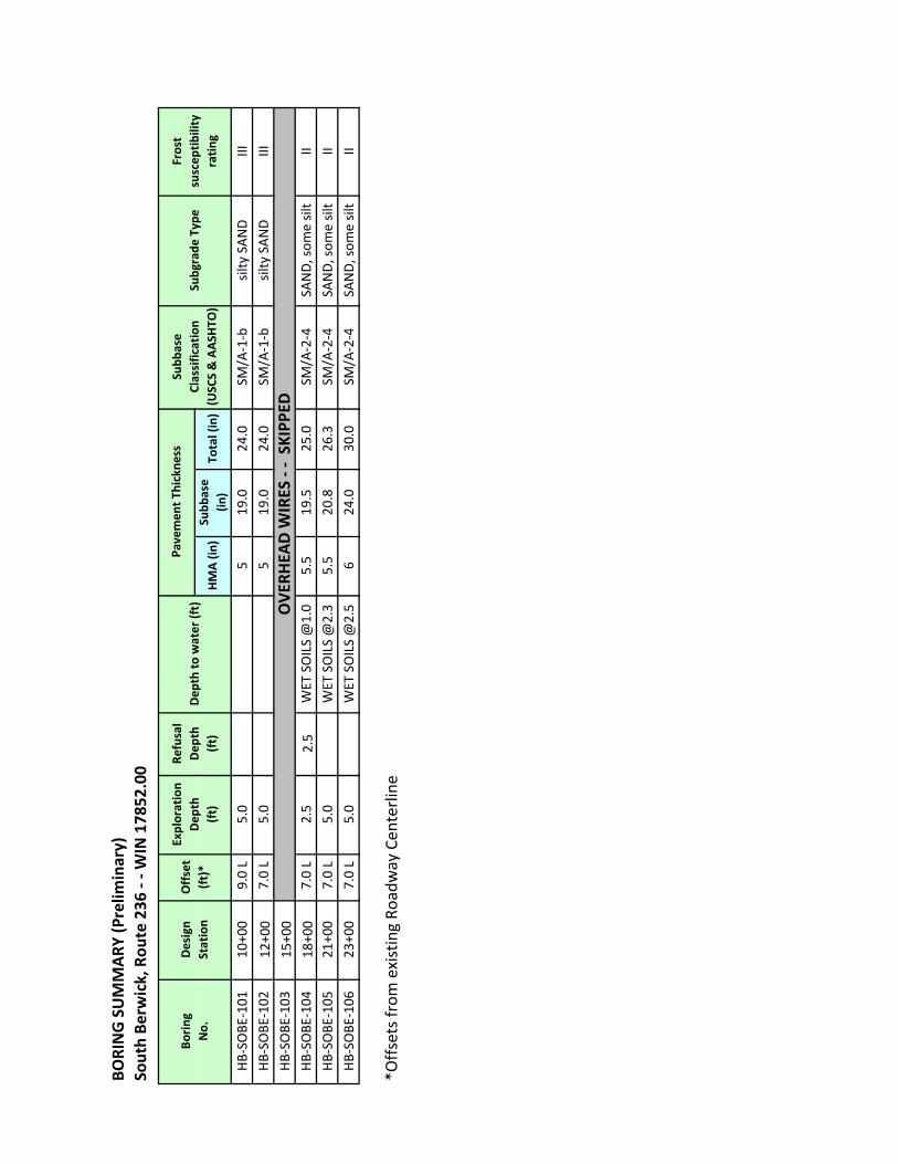
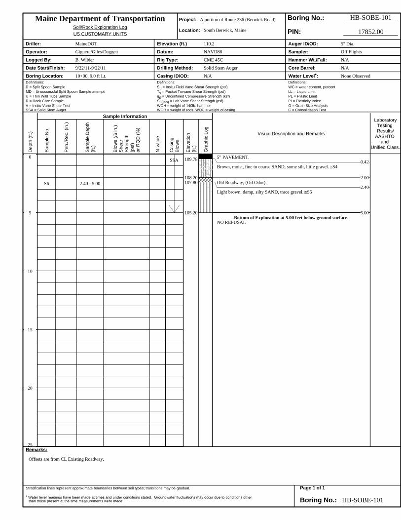
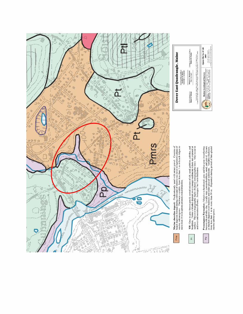
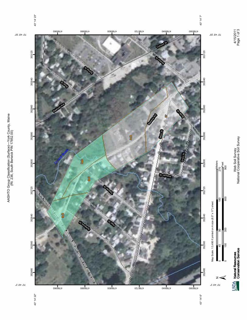
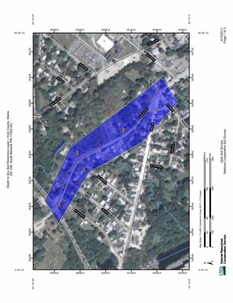
As-Built Plans No as-built plans for the original construction of this roadway were located. MaineDOT records indicate there were maintenance overlays placed in 1996, 2001, and 2004. Subsurface Investigations and Lab Testing Information Preliminary investigations included a Falling Weight Deflectometer (FWD) field analysis to determine pavement weaknesses and resilient modulus values for design, a GPR analysis to determine existing pavement structure material thicknesses, and 5 power auger borings to determine pavement structure materials thicknesses and properties. Existing information, including surficial geology and agricultural maps, was analyzed to determine what the pavement foundation soils may consist of and where possible surface and subsurface drainage problems may exist. All borings were drilled to a depth of 5 (+/-) feet using solid stem augers, unless refusal was encountered shallower than that depth. Subbase and subgrade soil samples were taken directly off the auger flights, and representative samples were tested by the MaineDOT testing lab in Bangor to determine the gradation and water content. The following summarizes the pavement structure materials thicknesses as found in the borings and soil properties from the lab testing data. A Boring Summary Sheet, boring logs, and Laboratory Testing Summary Sheet, and Grain Size distribution curves are attached at the end of this memo for your reference. Existing HMA The boring information indicates that the existing asphalt (HMA) ranges from 5” inches to 6” thick. No bituminous treated material or macadam was encountered beneath the HMA layer in any of the borings. Existing Base/Subbase The subsurface information indicates that the existing granular base/subbase thickness ranges from 19” to 24” in thickness. Lab testing data indicates that the existing granular material does not meet the requirements of Aggregate Subbase Course Gravel. All samples significantly exceed the specification requirements on the percentage passing the #200 sieve. Subgrade Soils The subsurface information indicates that the existing subgrade soils (24” below the existing roadway surface) consist predominately of a mix of sand and silt. This soil type is considered moderately to highly frost susceptible, with the susceptibility increasing with increasing silt contents. An old roadway surface approximately 5” thick was encountered at 24” below the existing surface at station 10+00. This old roadway consists of a material known as penetrated gravel; a process used in the 1940’s and 1950’s where liquid asphalt was sprayed onto the existing gravel to make a more stable wearing surface. The Dover East Quadrangle Surficial Geology map and the SCS maps indicate that there is a change in soil type approximately at Station 17+00. According to all maps, the subgrade soils should consist predominately of sand and gravel from the start of the project to Station 17+00, and have a higher silt content from Station 17+00 to the end of the project. We encountered the opposite in the borings where the subgrade soils have higher silt content from the start of the project to Station 17+00.
Highway Program
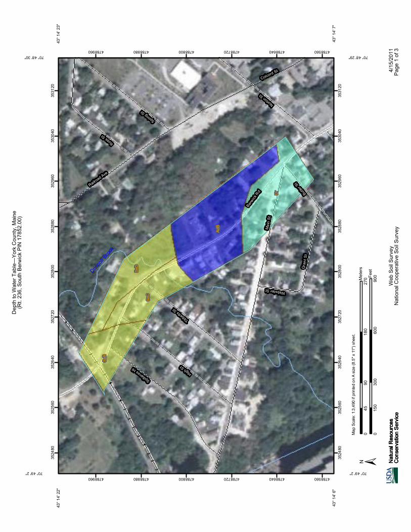
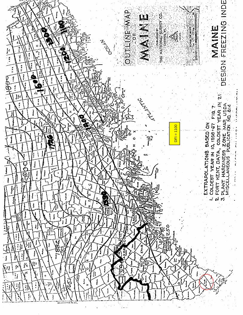
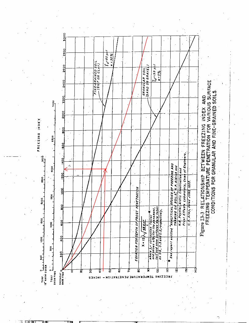
Bedrock Shallow refusal (5′ below the ground surface or less) was encountered in a boring at station 18+00. Additional investigations were conducted at this location and no obstructions, boulders, or refusal were encountered. Based on the information on the geology maps, shallow bedrock is not expected at this location, so hitting shallow refusal at this location is unexplained. Groundwater Shallow groundwater was not noted in any of the borings, however wet subbase and subgrade soils were encountered from Station 18+00 to the end of the project. These wet soils can be due to a high groundwater table, but it is more likely that it is a result of poor pavement structure drainage due to a “bathtub” pavement section. This area is also located in a sag section of the roadway, and with poor drainage, there is a strong possibility that water is collecting here. The Soil Conservation Survey for York County indicates that seasonal shallow groundwater is probable from 18+00 to the project end. Since the soils are considered frost susceptible, the significance of the shallow groundwater table is that it can supply the water needed to produce large frost heaves. Frost Penetration The anticipated depth of frost penetration and as interpolated from the Maine Design Freezing Index charts for this location is 42”. FWD Results FWD data was collected at 100 foot intervals in the right wheel path of the northbound travel lane. This field data was then processed to give us deflection data plots and an analysis of the existing pavement structures strengths and modulus values. Deflection data is very valuable because it provides information on where the existing pavement may have high deflections (weakness within the pavement or subgrade) and locations with low deflections where bedrock may be close to the surface. Sections with high deflections can also help identify areas that may need to be reconstructed. The FWD deflection data shows there are higher deflections predominately in the top 12” to 24” of the pavement structure, therefore the deflections are occurring in the asphalt and subbase layers and not in the subgrade. This indicates that the pavement structure is probably not adequate to support traffic loadings either because of material deterioration, or lack of structural support. The section with the highest deflections in the top 12” to 24” is from station 13+00 to 17+00. The FWD deflection data can also show where there are areas with a weak subgrade. The deflections in the subgrade are consistent, therefore the subgrade is probably providing a good foundation for the pavement structure. The subgrade resilient moduli (Mr) values as calculated from the FWD data range from 3058 psi to 8721 psi. Typically, Mr values over 8500 psi indicate the presence of shallow bedrock or stone base sections. A Mr value over 8500 psi was calculated at station 11+00. I do not think that there is shallow bedrock location, but there is a possibility that a stone base was placed during the original construction. Mr values under 3000 psi can indicate weak, wet, or soft subgrade soils. Deflection testing over existing culverts can also produce very low modulus values. A Mr value

Highway Program
of approximately 3000 psi was calculated at station 16+00. Values are between 3000 psi and 3500 psi from station 15+00 to 18+00. From the boring information, I am assuming these low values are due to wet and weak soils. The resilient modulus values calculated from the FWD data can also be used to determine the appropriate Mr value to use in the pavement design. For design purposes, the Mr value as calculated as of per Chapter 13 of the Highway Design Guide (the 75th percentile of all values between 3000 psi and 8500 psi) is 3700 psi. Mr values will increase once positive drainage is provided, therefore a value of 4000 psi is recommended for the pavement design. Recommendations The following are recommendations for the reconstruction of Route 236:
• The existing subbase material does not meet the MaineDOT specification requirements for subbase or base gravel and should be removed and replaced with new aggregate.
• Drainage improvements are recommended on the entire project length. These improvements should include provisions to remove both groundwater and surface water. Daylighting the subbase gravel to ditches or side slopes, or underdrain if daylighting is not possible will promote drainage of the pavement structure. Ditching or a closed drainage system will remove surface water and help to lower the groundwater table.
• Since the subgrade soils are frost susceptible, new subbase aggregate and drainage improvements will reduce the detrimental effects of frost on the pavement structure.
• The recommended resilient modulus to use for the pavement design based on drainage improvements and the FWD analysis values is 4000 psi.
Attachments Pavement Management Data Boring Summary Sheet Boring Logs Laboratory Summary Sheet Grain Size Curves Geoplans Geology Maps Frost Charts FWD Analysis GPR Data
Route Log Mile Detail ReportTide Load date: 10/14/2011
Tide year: 2011 Instance: TIDEPROD
Filter ElementsSelected Town Selected ROUTE Milepoint OffsetSouth Berwick 0236X 12.09 .7
NOTE: The end of this road in South Berwick is at milepoint 12.55.
Open Error Form VisiWeb™ Back
** Clicking on NODE ID will query and return Connecting Node information. ** EXPAND
Filter Results
Node ID Node Desc Node MP Fed. Func. Class
Pavement Data
Surface IRI PCR Inv Year
Rut Left
Rut Right
PIN
56698 3107199 S,BER,MAIN,PORTLAND ST. 12.09 Minor arterial Flexible 185 2.74 2009 .1 .2 004250.00 (1997)
56012 3106476 S.BER,MAIN,YOUNG ST. 12.17 Minor arterial Flexible 185 2.74 2009 .1 .2 011018.10 (2004)
55799 3106245 S.BER,MAIN,NORTON ST. 12.19 Minor arterial Flexible 185 2.74 2009 .1 .2 011018.10 (2004)
55800 Int of BERWICK RD, BUTLER ST, MAIN ST 12.24 Minor arterial Flexible 185 2.74 2009 .1 .2
011018.10 (2004)011018.21 (2004)008143.00 (2003)000625.00 (1994)
55801 Int of BERWICK RD, TIBBETTS ST 12.44 Minor arterial Flexible 156 3.46 2009 .1 .2
011018.10 (2004)007234.10 (1996)000625.00 (1994)
55802 Int of BERWICK RD, HIGH ST 12.49 Minor arterial Flexible 205 3.09 2009 .1 .3
011018.10 (2004)007234.10 (1996)000625.00 (1994)
55803 TL - Berwick, South Berwick 12.55 Minor arterial Flexible 236 2.65 2009 .1 .4
011018.10 (2004)007234.10 (1996)000625.00 (1994)
Node count: 7
Page 1 of 1RLM Web Filter
10/17/2011http://portal.lb.state.me.us/tideapps/pRLMform.ACCEPT_PROC
BORING SUMMARY
(Prelim
inary)
South Be
rwick, Rou
te 236
‐ ‐ W
IN 178
52.00
HB‐SO
BE‐101
10+00
9.0 L
5.0
519
.024
.0SM
/A‐1‐b
silty
SAND
III
HB‐SO
BE‐102
12+00
7.0 L
5.0
519
.024
.0SM
/A‐1‐b
silty
SAND
III
HB‐SO
BE‐103
15+00
HB‐SO
BE‐104
18+00
7.0 L
2.5
2.5
WET SOILS @1.0
5.5
19.5
25.0
SM/A‐2‐4
SAND, som
e silt
II
HB‐SO
BE‐105
21+00
7.0 L
5.0
WET SOILS @2.3
5.5
20.8
26.3
SM/A‐2‐4
SAND, som
e silt
II
HB‐SO
BE‐106
23+00
7.0 L
5.0
WET SOILS @2.5
624
.030
.0SM
/A‐2‐4
SAND, som
e silt
II
*Offsets from
existing Ro
adway Cen
terline
Boring
No.
Design
Station
Offset
(ft)*
OVER
HEA
D W
IRES ‐ ‐ SK
IPPE
D
Frost
suscep
tibility
rating
Exploration
Dep
th
(ft)
Refusal
Dep
th
(ft) Dep
th to water (ft)
HMA (in)
Subb
ase
Classification
(USCS & AASH
TO)
Subgrade
Type
Pavemen
t Th
ickn
ess
Total (in)
Subb
ase
(in)
0
5
10
15
20
25
S6 2.40 - 5.00
SSA 109.78
108.20107.80
105.20
5" PAVEMENT.0.42
Brown, moist, fine to coarse SAND, some silt, little gravel. ≅S4
2.00Old Roadway, (Oil Odor).
2.40Light brown, damp, silty SAND, trace gravel. ≅S5
5.00Bottom of Exploration at 5.00 feet below ground surface.
NO REFUSAL
Maine Department of Transportation Project: A portion of Route 236 (Berwick Road) Boring No.: HB-SOBE-101Soil/Rock Exploration Log Location: South Berwick, MaineUS CUSTOMARY UNITS PIN: 17852.00
Driller: MaineDOT Elevation (ft.) 110.2 Auger ID/OD: 5" Dia.
Operator: Giguere/Giles/Daggett Datum: NAVD88 Sampler: Off Flights
Logged By: B. Wilder Rig Type: CME 45C Hammer Wt./Fall: N/A
Date Start/Finish: 9/22/11-9/22/11 Drilling Method: Solid Stem Auger Core Barrel: N/A
Boring Location: 10+00, 9.0 ft Lt. Casing ID/OD: N/A Water Level*: None ObservedDefinitions: Definitions: Definitions:D = Split Spoon Sample Su = Insitu Field Vane Shear Strength (psf) WC = water content, percentMD = Unsuccessful Split Spoon Sample attempt Tv = Pocket Torvane Shear Strength (psf) LL = Liquid LimitU = Thin Wall Tube Sample qp = Unconfined Compressive Strength (ksf) PL = Plastic LimitR = Rock Core Sample Su(lab) = Lab Vane Shear Strength (psf) PI = Plasticity IndexV = Insitu Vane Shear Test WOH = weight of 140lb. hammer G = Grain Size AnalysisSSA = Solid Stem Auger WOR = weight of rods WOC = weight of casing C = Consolidation Test
Remarks:
Offsets are from CL Existing Roadway.
Stratification lines represent approximate boundaries between soil types; transitions may be gradual.
* Water level readings have been made at times and under conditions stated. Groundwater fluctuations may occur due to conditions otherthan those present at the time measurements were made. Boring No.: HB-SOBE-101
Dep
th (f
t.)
Sam
ple
No.
Sample Information
Pen
./Rec
. (in
.)
Sam
ple
Dep
th(ft
.)
Blo
ws
(/6 in
.)S
hear
Stre
ngth
(psf
)or
RQ
D (%
)
N-v
alue
Cas
ing
Blo
ws
Ele
vatio
n(ft
.)
Gra
phic
Log
Visual Description and Remarks
LaboratoryTesting Results/
AASHTO and
Unified Class.
Page 1 of 1
0
5
10
15
20
25
S4
S5
0.42 - 2.00
2.00 - 5.00
SSA 101.88
100.30
97.30
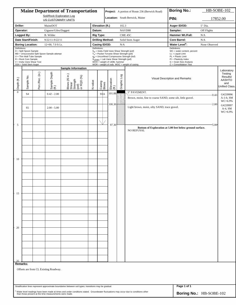
5" PAVEMENT.0.42
Brown, moist, fine to coarse SAND, some silt, little gravel.
2.00Light brown, moist, silty SAND, trace gravel.
5.00Bottom of Exploration at 5.00 feet below ground surface.
NO REFUSAL
G#239996A-1-b, SMWC=6.9%G#239997A-4, SM
WC=6.9%
Maine Department of Transportation Project: A portion of Route 236 (Berwick Road) Boring No.: HB-SOBE-102Soil/Rock Exploration Log Location: South Berwick, MaineUS CUSTOMARY UNITS PIN: 17852.00
Driller: MaineDOT Elevation (ft.) 102.3 Auger ID/OD: 5" Dia.
Operator: Giguere/Giles/Daggett Datum: NAVD88 Sampler: Off Flights
Logged By: B. Wilder Rig Type: CME 45C Hammer Wt./Fall: N/A
Date Start/Finish: 9/22/11-9/22/11 Drilling Method: Solid Stem Auger Core Barrel: N/A
Boring Location: 12+00, 7.0 ft Lt. Casing ID/OD: N/A Water Level*: None ObservedDefinitions: Definitions: Definitions:D = Split Spoon Sample Su = Insitu Field Vane Shear Strength (psf) WC = water content, percentMD = Unsuccessful Split Spoon Sample attempt Tv = Pocket Torvane Shear Strength (psf) LL = Liquid LimitU = Thin Wall Tube Sample qp = Unconfined Compressive Strength (ksf) PL = Plastic LimitR = Rock Core Sample Su(lab) = Lab Vane Shear Strength (psf) PI = Plasticity IndexV = Insitu Vane Shear Test WOH = weight of 140lb. hammer G = Grain Size AnalysisSSA = Solid Stem Auger WOR = weight of rods WOC = weight of casing C = Consolidation Test
Remarks:
Offsets are from CL Existing Roadway.
Stratification lines represent approximate boundaries between soil types; transitions may be gradual.
* Water level readings have been made at times and under conditions stated. Groundwater fluctuations may occur due to conditions otherthan those present at the time measurements were made. Boring No.: HB-SOBE-102
Dep
th (f
t.)
Sam
ple
No.
Sample Information
Pen
./Rec
. (in
.)
Sam
ple
Dep
th(ft
.)
Blo
ws
(/6 in
.)S
hear
Stre
ngth
(psf
)or
RQ
D (%
)
N-v
alue
Cas
ing
Blo
ws
Ele
vatio
n(ft
.)
Gra
phic
Log
Visual Description and Remarks
LaboratoryTesting Results/
AASHTO and
Unified Class.
Page 1 of 1
0
5
10
15
20
25
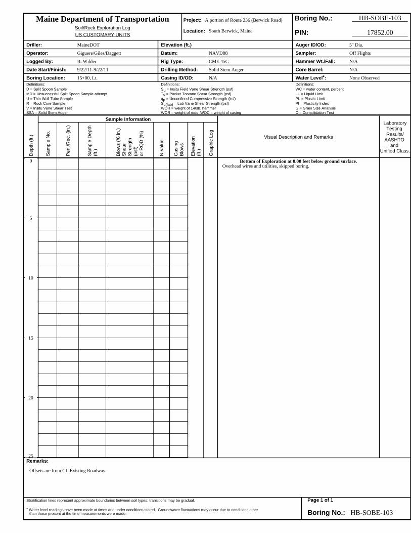
Bottom of Exploration at 0.00 feet below ground surface.Overhead wires and utilities, skipped boring.
Maine Department of Transportation Project: A portion of Route 236 (Berwick Road) Boring No.: HB-SOBE-103Soil/Rock Exploration Log Location: South Berwick, MaineUS CUSTOMARY UNITS PIN: 17852.00
Driller: MaineDOT Elevation (ft.) Auger ID/OD: 5" Dia.
Operator: Giguere/Giles/Daggett Datum: NAVD88 Sampler: Off Flights
Logged By: B. Wilder Rig Type: CME 45C Hammer Wt./Fall: N/A
Date Start/Finish: 9/22/11-9/22/11 Drilling Method: Solid Stem Auger Core Barrel: N/A
Boring Location: 15+00, Lt. Casing ID/OD: N/A Water Level*: None ObservedDefinitions: Definitions: Definitions:D = Split Spoon Sample Su = Insitu Field Vane Shear Strength (psf) WC = water content, percentMD = Unsuccessful Split Spoon Sample attempt Tv = Pocket Torvane Shear Strength (psf) LL = Liquid LimitU = Thin Wall Tube Sample qp = Unconfined Compressive Strength (ksf) PL = Plastic LimitR = Rock Core Sample Su(lab) = Lab Vane Shear Strength (psf) PI = Plasticity IndexV = Insitu Vane Shear Test WOH = weight of 140lb. hammer G = Grain Size AnalysisSSA = Solid Stem Auger WOR = weight of rods WOC = weight of casing C = Consolidation Test
Remarks:
Offsets are from CL Existing Roadway.
Stratification lines represent approximate boundaries between soil types; transitions may be gradual.
* Water level readings have been made at times and under conditions stated. Groundwater fluctuations may occur due to conditions otherthan those present at the time measurements were made. Boring No.: HB-SOBE-103
Dep
th (f
t.)
Sam
ple
No.
Sample Information
Pen
./Rec
. (in
.)
Sam
ple
Dep
th(ft
.)
Blo
ws
(/6 in
.)S
hear
Stre
ngth
(psf
)or
RQ
D (%
)
N-v
alue
Cas
ing
Blo
ws
Ele
vatio
n(ft
.)
Gra
phic
Log
Visual Description and Remarks
LaboratoryTesting Results/
AASHTO and
Unified Class.
Page 1 of 1
0
5
10
15
20
25
SSA 77.7477.20
75.70
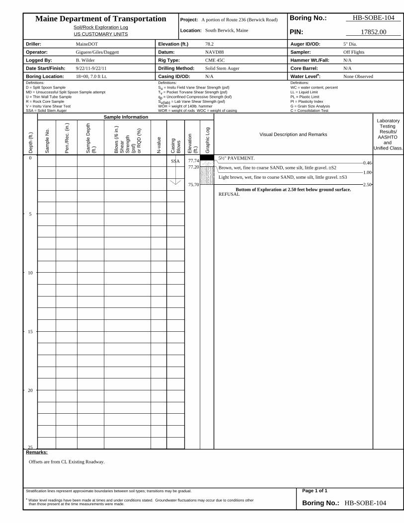
5½" PAVEMENT.0.46
Brown, wet, fine to coarse SAND, some silt, little gravel. ≅S21.00
Light brown, wet, fine to coarse SAND, some silt, little gravel. ≅S32.50
Bottom of Exploration at 2.50 feet below ground surface.REFUSAL
Maine Department of Transportation Project: A portion of Route 236 (Berwick Road) Boring No.: HB-SOBE-104Soil/Rock Exploration Log Location: South Berwick, MaineUS CUSTOMARY UNITS PIN: 17852.00
Driller: MaineDOT Elevation (ft.) 78.2 Auger ID/OD: 5" Dia.
Operator: Giguere/Giles/Daggett Datum: NAVD88 Sampler: Off Flights
Logged By: B. Wilder Rig Type: CME 45C Hammer Wt./Fall: N/A
Date Start/Finish: 9/22/11-9/22/11 Drilling Method: Solid Stem Auger Core Barrel: N/A
Boring Location: 18+00, 7.0 ft Lt. Casing ID/OD: N/A Water Level*: None ObservedDefinitions: Definitions: Definitions:D = Split Spoon Sample Su = Insitu Field Vane Shear Strength (psf) WC = water content, percentMD = Unsuccessful Split Spoon Sample attempt Tv = Pocket Torvane Shear Strength (psf) LL = Liquid LimitU = Thin Wall Tube Sample qp = Unconfined Compressive Strength (ksf) PL = Plastic LimitR = Rock Core Sample Su(lab) = Lab Vane Shear Strength (psf) PI = Plasticity IndexV = Insitu Vane Shear Test WOH = weight of 140lb. hammer G = Grain Size AnalysisSSA = Solid Stem Auger WOR = weight of rods WOC = weight of casing C = Consolidation Test
Remarks:
Offsets are from CL Existing Roadway.
Stratification lines represent approximate boundaries between soil types; transitions may be gradual.
* Water level readings have been made at times and under conditions stated. Groundwater fluctuations may occur due to conditions otherthan those present at the time measurements were made. Boring No.: HB-SOBE-104
Dep
th (f
t.)
Sam
ple
No.
Sample Information
Pen
./Rec
. (in
.)
Sam
ple
Dep
th(ft
.)
Blo
ws
(/6 in
.)S
hear
Stre
ngth
(psf
)or
RQ
D (%
)
N-v
alue
Cas
ing
Blo
ws
Ele
vatio
n(ft
.)
Gra
phic
Log
Visual Description and Remarks
LaboratoryTesting Results/
AASHTO and
Unified Class.
Page 1 of 1

0
5
10
15
20
25
S3 2.20 - 5.00
SSA 95.34
93.60
90.80
5½" PAVEMENT.0.46
Brown, moist, fine to coarse SAND, soem silt, little gravel. ≅S1
2.20Light brown, wet, fine to coarse SAND, some silt, little gravel.
5.00Bottom of Exploration at 5.00 feet below ground surface.
NO REFUSAL
G#239998A-2-4, SMWC=9.1%
Maine Department of Transportation Project: A portion of Route 236 (Berwick Road) Boring No.: HB-SOBE-105Soil/Rock Exploration Log Location: South Berwick, MaineUS CUSTOMARY UNITS PIN: 17852.00
Driller: MaineDOT Elevation (ft.) 95.8 Auger ID/OD: 5" Dia.
Operator: Giguere/Giles/Daggett Datum: NAVD88 Sampler: Off Flights
Logged By: B. Wilder Rig Type: CME 45C Hammer Wt./Fall: N/A
Date Start/Finish: 9/22/11-9/22/11 Drilling Method: Solid Stem Auger Core Barrel: N/A
Boring Location: 21+00, 7.0 ft Lt. Casing ID/OD: N/A Water Level*: None ObservedDefinitions: Definitions: Definitions:D = Split Spoon Sample Su = Insitu Field Vane Shear Strength (psf) WC = water content, percentMD = Unsuccessful Split Spoon Sample attempt Tv = Pocket Torvane Shear Strength (psf) LL = Liquid LimitU = Thin Wall Tube Sample qp = Unconfined Compressive Strength (ksf) PL = Plastic LimitR = Rock Core Sample Su(lab) = Lab Vane Shear Strength (psf) PI = Plasticity IndexV = Insitu Vane Shear Test WOH = weight of 140lb. hammer G = Grain Size AnalysisSSA = Solid Stem Auger WOR = weight of rods WOC = weight of casing C = Consolidation Test
Remarks:
Offsets are from CL Existing Roadway.
Stratification lines represent approximate boundaries between soil types; transitions may be gradual.
* Water level readings have been made at times and under conditions stated. Groundwater fluctuations may occur due to conditions otherthan those present at the time measurements were made. Boring No.: HB-SOBE-105
Dep
th (f
t.)
Sam
ple
No.
Sample Information
Pen
./Rec
. (in
.)
Sam
ple
Dep
th(ft
.)
Blo
ws
(/6 in
.)S
hear
Stre
ngth
(psf
)or
RQ
D (%
)
N-v
alue
Cas
ing
Blo
ws
Ele
vatio
n(ft
.)
Gra
phic
Log
Visual Description and Remarks
LaboratoryTesting Results/
AASHTO and
Unified Class.
Page 1 of 1
0
5
10
15
20
25
S1
S2
0.50 - 2.50
2.50 - 5.00
SSA 105.30
103.30
100.80
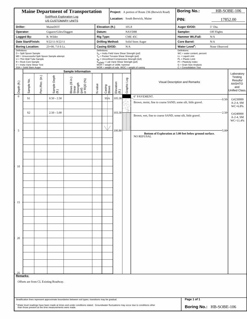
6" PAVEMENT.0.50
Brown, moist, fine to coarse SAND, some silt, little gravel.
2.50Brown, wet, fine to coarse SAND, some silt, little gravel.
5.00Bottom of Exploration at 5.00 feet below ground surface.
NO REFUSAL
G#239999A-2-4, SMWC=6.8%
G#240000A-2-4, SMWC=11.4%
Maine Department of Transportation Project: A portion of Route 236 (Berwick Road) Boring No.: HB-SOBE-106Soil/Rock Exploration Log Location: South Berwick, MaineUS CUSTOMARY UNITS PIN: 17852.00
Driller: MaineDOT Elevation (ft.) 105.8 Auger ID/OD: 5" Dia.
Operator: Giguere/Giles/Daggett Datum: NAVD88 Sampler: Off Flights
Logged By: B. Wilder Rig Type: CME 45C Hammer Wt./Fall: N/A
Date Start/Finish: 9/22/11-9/22/11 Drilling Method: Solid Stem Auger Core Barrel: N/A
Boring Location: 23+00, 7.0 ft Lt. Casing ID/OD: N/A Water Level*: None ObservedDefinitions: Definitions: Definitions:D = Split Spoon Sample Su = Insitu Field Vane Shear Strength (psf) WC = water content, percentMD = Unsuccessful Split Spoon Sample attempt Tv = Pocket Torvane Shear Strength (psf) LL = Liquid LimitU = Thin Wall Tube Sample qp = Unconfined Compressive Strength (ksf) PL = Plastic LimitR = Rock Core Sample Su(lab) = Lab Vane Shear Strength (psf) PI = Plasticity IndexV = Insitu Vane Shear Test WOH = weight of 140lb. hammer G = Grain Size AnalysisSSA = Solid Stem Auger WOR = weight of rods WOC = weight of casing C = Consolidation Test
Remarks:
Offsets are from CL Existing Roadway.
Stratification lines represent approximate boundaries between soil types; transitions may be gradual.
* Water level readings have been made at times and under conditions stated. Groundwater fluctuations may occur due to conditions otherthan those present at the time measurements were made. Boring No.: HB-SOBE-106
Dep
th (f
t.)
Sam
ple
No.
Sample Information
Pen
./Rec
. (in
.)
Sam
ple
Dep
th(ft
.)
Blo
ws
(/6 in
.)S
hear
Stre
ngth
(psf
)or
RQ
D (%
)
N-v
alue
Cas
ing
Blo
ws
Ele
vatio
n(ft
.)
Gra
phic
Log
Visual Description and Remarks
LaboratoryTesting Results/
AASHTO and
Unified Class.
Page 1 of 1
Station Offset Depth Reference G.S.D.C. W.C. L.L. P.I.
(Feet) (Feet) (Feet) Number Sheet % Unified AASHTO Frost
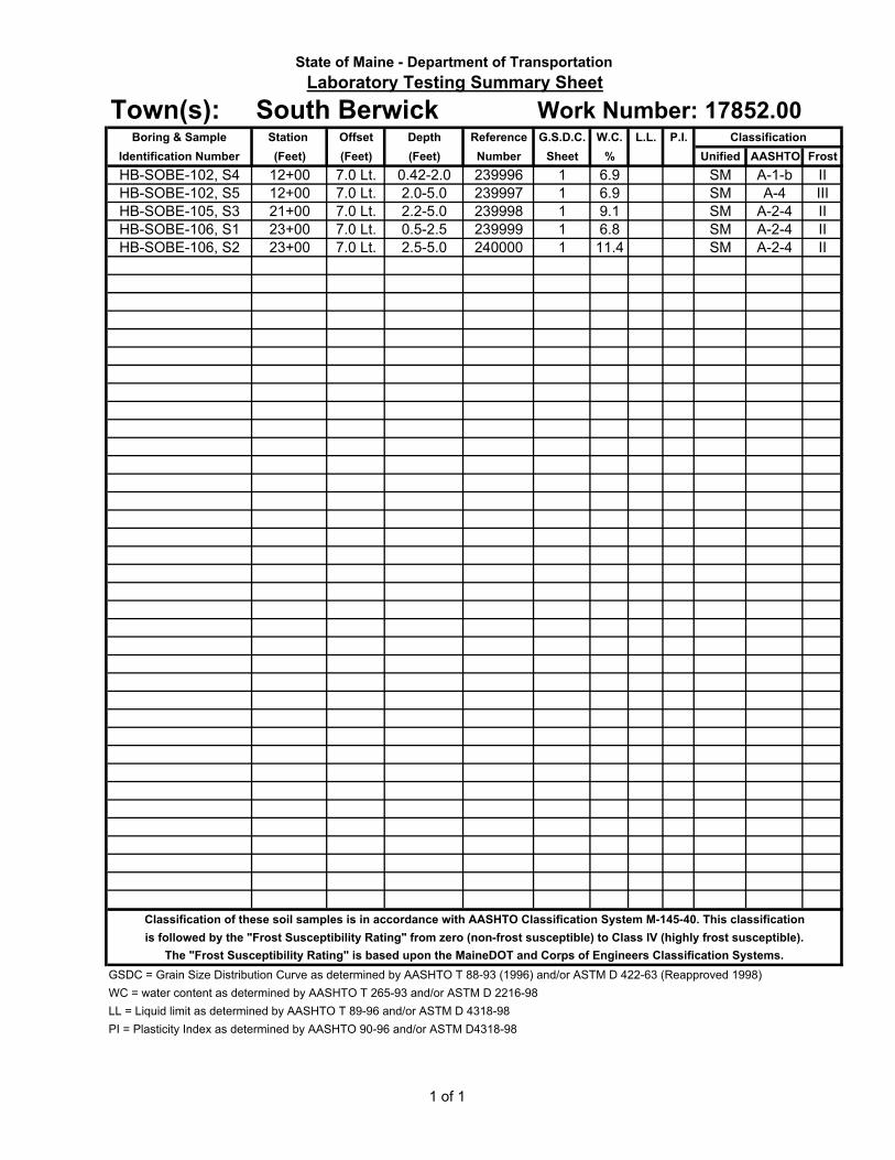
12+00 7.0 Lt. 0.42-2.0 239996 1 6.9 SM A-1-b II
12+00 7.0 Lt. 2.0-5.0 239997 1 6.9 SM A-4 III
21+00 7.0 Lt. 2.2-5.0 239998 1 9.1 SM A-2-4 II
23+00 7.0 Lt. 0.5-2.5 239999 1 6.8 SM A-2-4 II
23+00 7.0 Lt. 2.5-5.0 240000 1 11.4 SM A-2-4 II
Classification of these soil samples is in accordance with AASHTO Classification System M-145-40. This classification
is followed by the "Frost Susceptibility Rating" from zero (non-frost susceptible) to Class IV (highly frost susceptible).
The "Frost Susceptibility Rating" is based upon the MaineDOT and Corps of Engineers Classification Systems.
GSDC = Grain Size Distribution Curve as determined by AASHTO T 88-93 (1996) and/or ASTM D 422-63 (Reapproved 1998)
WC = water content as determined by AASHTO T 265-93 and/or ASTM D 2216-98
LL = Liquid limit as determined by AASHTO T 89-96 and/or ASTM D 4318-98
PI = Plasticity Index as determined by AASHTO 90-96 and/or ASTM D4318-98
Identification Number
HB-SOBE-102, S4
Work Number: 17852.00
HB-SOBE-102, S5
Classification
HB-SOBE-106, S1
HB-SOBE-106, S2
State of Maine - Department of Transportation
Laboratory Testing Summary Sheet
Town(s): South BerwickBoring & Sample
HB-SOBE-105, S3
1 of 1
3"
2"1-1/2"
1"
3/4"
1/2"
3/8"
1/4"
#4
#8
#10
#16
#20
#40
#60
#100
#200
0.05
0.03
0.010
0.005
0.001
76.2
50.8
38.1
25.4
19.05
12.7
9.53
6.35
4.75
2.36
2.00
1.18
0.85
0.426
0.25
0.15
0.075
0.05
0.03
0.005
GRAVEL
SAND
SILT
SIEVE ANALYSIS
US Standard Sieve Numbers
HYDROMETER ANALYSIS
Grain Diameter, mm
State of Maine Department of Transportation
GRAIN SIZE DISTRIBUTIO
N CURVE
100
10
10.1
0.01
0.001
Grain Diameter, mm
0
10
20
30
40
50
60
70
80
90
100
Percent Finer by Weight
100
90
80
70
60
50
40
30
20
10
0
Percent Retained by Weight
CLAY
SHEET NO.
UNIFIED CLASSIFICATION
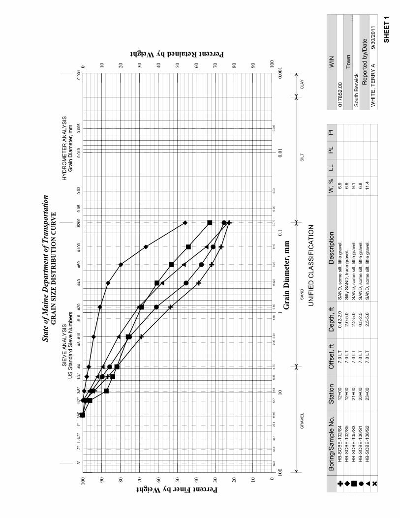
SAND, some silt, little gravel.
SAND, some silt, little gravel.
SAND, some silt, little gravel.
Silty SAND, trace gravel.
6.9
11.4
SAND, some silt, little gravel.
6.9
9.1
6.8
HB-SOBE-102/S4
HB-SOBE-106/S2
HB-SOBE-102/S5
HB-SOBE-105/S3
HB-SOBE-106/S1
0.42-2.0
2.5-5.0
2.0-5.0
2.2-5.0
0.5-2.5
Depth, ft
Boring/Sample No.
Description
W, %
LL
PL
PI
� ��� � ��� � ��� � ��� � ��� � ���
SHEET 1
South Berwick
017852.00
WHITE, TERRY A 9/30/2011
WIN
Town
Reported by/Date
7.0 LT
7.0 LT
7.0 LT
7.0 LT
7.0 LT
Offset, ft
12+00
23+00
12+00
21+00
23+00
Station
Drisco
ll Bro
ok
Mai
nS
t
Berw
ickRd
Railroad Ave
HighSt
RossSt
SpillanesHl
NortonSt
SpringSt
TibbettsSt
Gra
ntS
tBut
lerSt
Colcord St
WebsterSt
Ur
AdB
SeD
SeC
SeB
3524
80
3524
80
3525
60
3525
60
3526
40
3526
40
3527
20
3527
20
3528
00
3528
00
3528
80
3528
80
3529
60
3529
60
3530
40
3530
40
3531
20
3531
20
4788560
4788560
4788640
4788640
4788720
4788720
4788800
4788800
4788880
4788880
4788960
4788960
030
060
090
015
0Fe
et0
9018
027
045
Met
ers
43°1
4'23
''
70°48'30''
43°1
4'7'
'
70°48'29''
43°1
4'6'
'
43°1
4'22
''70°49'2''70°49'2''
Map
Scal
e:1:
3,49
0if
prin
ted
onA
size
(8.5
"x11
")sh
eet.A
AS
HTO
Gro
up C
lass
ifica
tion
(Sur
face
)—Y
ork
Cou
nty,
Mai
ne(R
t. 23
6, S
outh
Ber
wic
k P
IN 1
7852
.00)
Nat
ural
Res
ourc
esN
atur
al R
esou
rces
Nat
ural
Res
ourc
esN
atur
al R
esou
rces
Con
serv
atio
n S
ervi
ceC
onse
rvat
ion
Ser
vice
Con
serv
atio
n S
ervi
ceC
onse
rvat
ion
Ser
vice
Web
Soi
l Sur
vey
Nat
iona
l Coo
pera
tive
Soi
l Sur
vey
4/15
/201
1P
age
1 of
3
Drisco
ll Bro
ok
Mai
nS
t
Berw
ickRd
Railroad Ave
HighSt
RossSt
SpillanesHl
NortonSt
SpringSt
TibbettsSt
Gra
ntS
tBut
lerSt
Colcord St
WebsterSt
Ur
AdB
SeD
SeC
SeB
3524
80
3524
80
3525
60
3525
60
3526
40
3526
40
3527
20
3527
20
3528
00
3528
00
3528
80
3528
80
3529
60
3529
60
3530
40
3530
40
3531
20
3531
20
4788560
4788560
4788640
4788640
4788720
4788720
4788800
4788800
4788880
4788880
4788960
4788960
030
060
090
015
0Fe
et0
9018
027
045
Met
ers
43°1
4'23
''
70°48'30''
43°1
4'7'
'
70°48'29''
43°1
4'6'
'
43°1
4'22
''70°49'2''70°49'2''
Map
Scal
e:1:
3,49
0if
prin
ted
onA
size
(8.5
"x11
")sh
eet.
Dep
th to
Any
Soi
l Res
trict
ive
Laye
r—Y
ork
Cou
nty,
Mai
ne(R
t. 23
6, S
outh
Ber
wic
k P
IN 1
7852
.00)
Nat
ural
Res
ourc
esN
atur
al R
esou
rces
Nat
ural
Res
ourc
esN
atur
al R
esou
rces
Con
serv
atio
n S
ervi
ceC
onse
rvat
ion
Ser
vice
Con
serv
atio
n S
ervi
ceC
onse
rvat
ion
Ser
vice
Web
Soi
l Sur
vey
Nat
iona
l Coo
pera
tive
Soi
l Sur
vey
4/15
/201
1P
age
1 of
3
Drisco
ll Bro
ok
Mai
nS
t
Berw
ickRd
Railroad Ave
HighSt
RossSt
SpillanesHl
NortonSt
SpringSt
TibbettsSt
Gra
ntS
tBut
lerSt
Colcord St
WebsterSt
Ur
AdB
SeD
SeC
SeB
3524
80
3524
80
3525
60
3525
60
3526
40
3526
40
3527
20
3527
20
3528
00
3528
00
3528
80
3528
80
3529
60
3529
60
3530
40
3530
40
3531
20
3531
20
4788560
4788560
4788640
4788640
4788720
4788720
4788800
4788800
4788880
4788880
4788960
4788960
030
060
090
015
0Fe
et0
9018
027
045
Met
ers
43°1
4'23
''
70°48'30''
43°1
4'7'
'
70°48'29''
43°1
4'6'
'
43°1
4'22
''70°49'2''70°49'2''
Map
Scal
e:1:
3,49
0if
prin
ted
onA
size
(8.5
"x11
")sh
eet.
Dep
th to
Wat
er T
able
—Y
ork
Cou
nty,
Mai
ne(R
t. 23
6, S
outh
Ber
wic
k P
IN 1
7852
.00)
Nat
ural
Res
ourc
esN
atur
al R
esou
rces
Nat
ural
Res
ourc
esN
atur
al R
esou
rces
Con
serv
atio
n S
ervi
ceC
onse
rvat
ion
Ser
vice
Con
serv
atio
n S
ervi
ceC
onse
rvat
ion
Ser
vice
Web
Soi
l Sur
vey
Nat
iona
l Coo
pera
tive
Soi
l Sur
vey
4/15
/201
1P
age
1 of
3
Drisco
ll Bro
ok
Mai
nS
t
Berw
ickRd
Railroad Ave
HighSt
RossSt
SpillanesHl
NortonSt
SpringSt
TibbettsSt
Gra
ntS
tBut
lerSt
Colcord St
WebsterSt
Ur
AdB
SeD
SeC
SeB
3524
80
3524
80
3525
60
3525
60
3526
40
3526
40
3527
20
3527
20
3528
00
3528
00
3528
80
3528
80
3529
60
3529
60
3530
40
3530
40
3531
20
3531
20
4788560
4788560
4788640
4788640
4788720
4788720
4788800
4788800
4788880
4788880
4788960
4788960
030
060
090
015
0Fe
et0
9018
027
045
Met
ers
43°1
4'23
''
70°48'30''
43°1
4'7'
'
70°48'29''
43°1
4'6'
'
43°1
4'22
''70°49'2''70°49'2''
Map
Scal
e:1:
3,49
0if
prin
ted
onA
size
(8.5
"x11
")sh
eet.
Fros
t Act
ion—
Yor
k C
ount
y, M
aine
(Rt.
236,
Sou
th B
erw
ick
PIN
178
52.0
0)
Nat
ural
Res
ourc
esN
atur
al R
esou
rces
Nat
ural
Res
ourc
esN
atur
al R
esou
rces
Con
serv
atio
n S
ervi
ceC
onse
rvat
ion
Ser
vice
Con
serv
atio
n S
ervi
ceC
onse
rvat
ion
Ser
vice
Web
Soi
l Sur
vey
Nat
iona
l Coo
pera
tive
Soi
l Sur
vey
4/15
/201
1P
age
1 of
3
DF
I=11
00
October 20, 2011
Falling Weight Deflectometer (FWD) Summary Sheet
Project #: 17852.00 Town(s): South Berwick Route(s): #232 Date Tested: 06/29/2011 Requested By: K. Gross Direction of Testing: South to North # Of FWD tests: 17 # Of Power Augers/Spoons - 5 Design Life: N/A Future 18-kip ESALs (Design Life): See Below Initial Serviceability: N/A Terminal Serviceability: N/A Reliability Level: N/A Overall Standard Deviation: N/A Locations Station (Feet) Description Used Project Stationing Comments: Subgrade Modulus values only. Pavement depths used for FWD analysis were taken from Ground Penetrating Radar (GPR) Estimated Pavement Depth Summary Sheet. Please see “Explanation of GPR Data Collection and Analysis” located at the top of the Sheet for details on how the estimated pavement depths were developed.
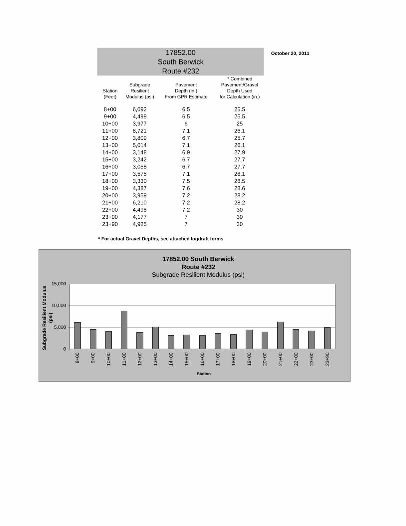
17852.00 October 20, 2011
South BerwickRoute #232
* CombinedSubgrade Pavement Pavement/Gravel
Station Resilient Depth (in.) Depth Used(Feet) Modulus (psi) From GPR Estimate for Calculation (in.)
8+00 6,092 6.5 25.59+00 4,499 6.5 25.5
10+00 3,977 6 2511+00 8,721 7.1 26.112+00 3,809 6.7 25.713+00 5,014 7.1 26.114+00 3,148 6.9 27.915+00 3,242 6.7 27.716+00 3,058 6.7 27.717+00 3,575 7.1 28.118+00 3,330 7.5 28.519+00 4,387 7.6 28.620+00 3,959 7.2 28.221+00 6,210 7.2 28.222+00 4,498 7.2 3023+00 4,177 7 3023+90 4,925 7 30
* For actual Gravel Depths, see attached logdraft forms
17852.00 South Berwick Route #232
Subgrade Resilient Modulus (psi)
0
5,000
10,000
15,000
8+00
9+00
10+0
0
11+0
0
12+0
0
13+0
0
14+0
0
15+0
0
16+0
0
17+0
0
18+0
0
19+0
0
20+0
0
21+0
0
22+0
0
23+0
0
23+9
0
Station
Subg
rade
Res
ilien
t Mod
ulus
(p
si)
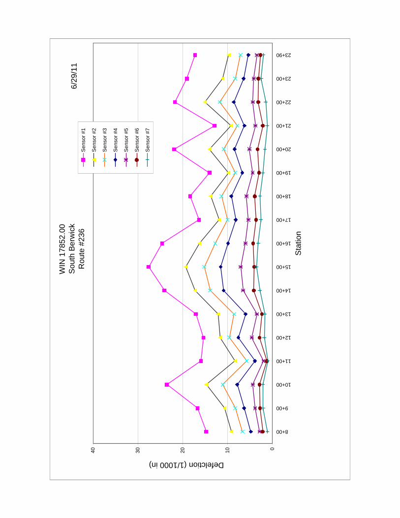
WIN
178
52.0
0 S
outh
Ber
wic
kR
oute
#23
6
0102030408+00
9+00
10+00
11+00
12+00
13+00
14+00
15+00
16+00
17+00
18+00
19+00
20+00
21+00
22+00
23+00
23+90
Sta
tion
Defelction (1/1000 in)
Sen
sor #
1
Sen
sor #
2
Sen
sor #
3
Sen
sor #
4
Sen
sor #
5
Sen
sor #
6
Sen
sor #
7
6/29
/11
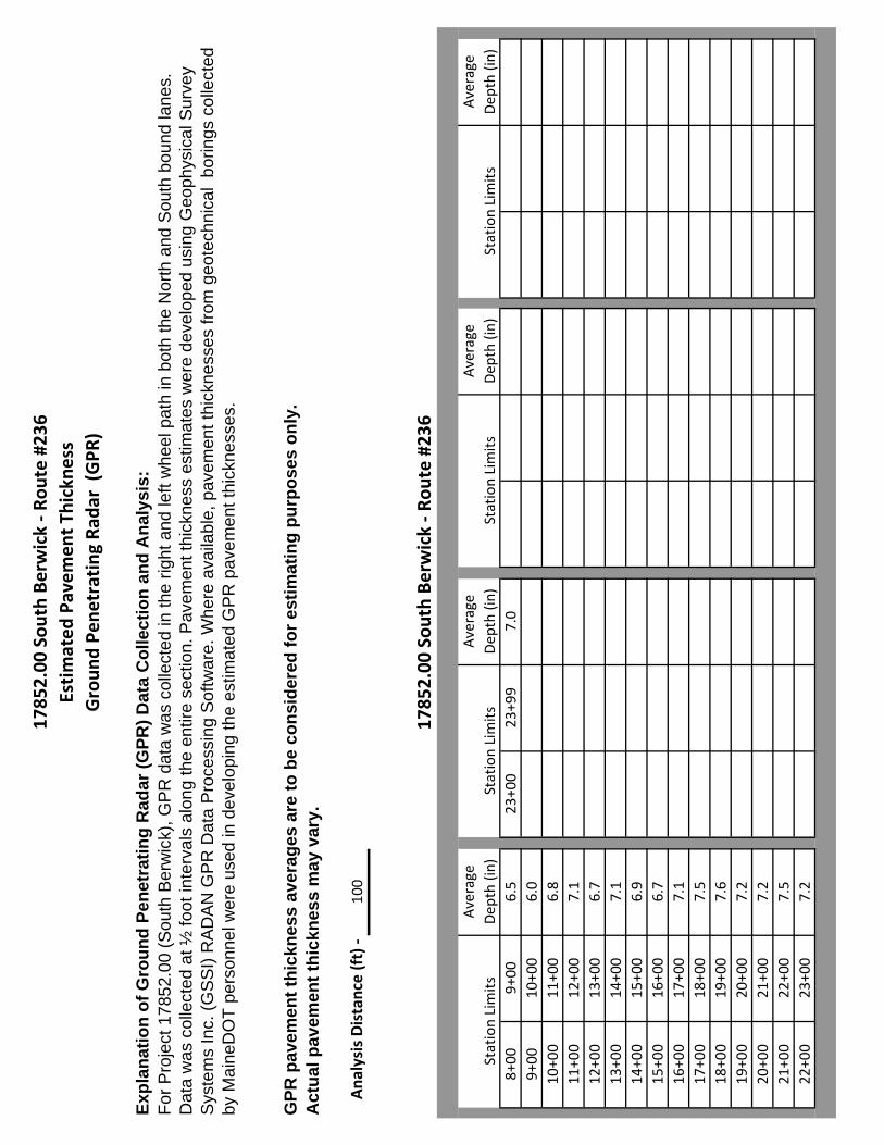
1785
2.00
Sou
th Berwick ‐ R
oute #23
6Estimated
Pavem
ent Th
ickn
ess
Groun
d Pe
netrating Ra
dar (G
PR)
Expl
anat
ion
of G
roun
d Pe
netr
atin
g R
adar
(GPR
) Dat
a C
olle
ctio
n an
d A
naly
sis:
GPR
pav
emen
t thi
ckne
ss a
vera
ges
are
to b
e co
nsid
ered
for e
stim
atin
g pu
rpos
es o
nly.
Act
ual p
avem
ent t
hick
ness
may
var
y.
Ana
lysis Distance (ft) ‐
100
1785
2.00
Sou
th Berwick ‐ R
oute #23
6
Average
Average
Average
Average
Station Limits
Dep
th (in)
Station Limits
Dep
th (in)
Station Limits
Dep
th (in)
Station Limits
Dep
th (in)
8+00
9+00
6.5
23+00
23+99
7.0
9+00
10+00
6.0
10+00
11+00
6.8
11+00
12+00
7.1
12+00
13+00
6.7
13+00
14+00
7.1
14+00
15+00
6.9
15+00
16+00
6.7
16+00
17+00
7.1
17+00
18+00
7.5
18+00
19+00
7.6
19+00
20+00
7.2
20+00
21+00
7.2
21+00
22+00
7.5
22+00
23+00
7.2
For P
roje
ct 1
7852
.00
(Sou
th B
erw
ick)
, GP
R d
ata
was
col
lect
ed in
the
right
and
left
whe
el p
ath
in b
oth
the
Nor
th a
nd S
outh
bou
nd la
nes.
D
ata
was
col
lect
ed a
t ½ fo
ot in
terv
als
alon
g th
e en
tire
sect
ion.
Pav
emen
t thi
ckne
ss e
stim
ates
wer
e de
velo
ped
usin
g G
eoph
ysic
al S
urve
y S
yste
ms
Inc.
(GS
SI)
RA
DA
N G
PR
Dat
a P
roce
ssin
g S
oftw
are.
Whe
re a
vaila
ble,
pav
emen
t thi
ckne
sses
from
geo
tech
nica
l bo
rings
col
lect
ed
by M
aine
DO
T pe
rson
nel w
ere
used
in d
evel
opin
g th
e es
timat
ed G
PR
pav
emen
t thi
ckne
sses
.