fisher level instruments - spartan controls/media/resources/fisher/pf/84... · fisher level...
TRANSCRIPT
www.Fisher.com
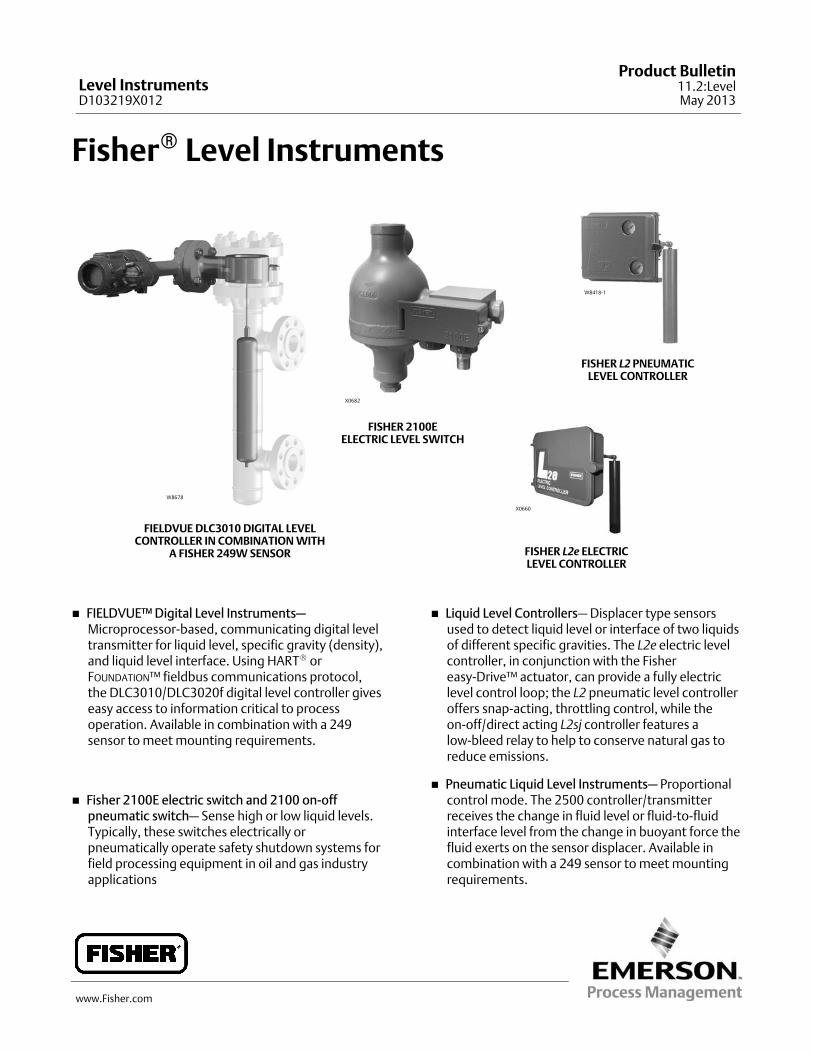
Fisher� Level Instruments
W8678
FIELDVUE DLC3010 DIGITAL LEVELCONTROLLER IN COMBINATION WITH
A FISHER 249W SENSOR
FISHER 2100EELECTRIC LEVEL SWITCH
X0660
FISHER L2e ELECTRICLEVEL CONTROLLER
X0682
W8418‐1
FISHER L2 PNEUMATICLEVEL CONTROLLER
� FIELDVUE™ Digital Level Instruments—Microprocessor‐based, communicating digital leveltransmitter for liquid level, specific gravity (density),and liquid level interface. Using HART� orFOUNDATION™ fieldbus communications protocol,the DLC3010/DLC3020f digital level controller giveseasy access to information critical to processoperation. Available in combination with a 249sensor to meet mounting requirements.
� Fisher 2100E electric switch and 2100 on-offpneumatic switch— Sense high or low liquid levels.Typically, these switches electrically orpneumatically operate safety shutdown systems forfield processing equipment in oil and gas industryapplications
� Liquid Level Controllers— Displacer type sensorsused to detect liquid level or interface of two liquidsof different specific gravities. The L2e electric levelcontroller, in conjunction with the Fishereasy-Drive™ actuator, can provide a fully electriclevel control loop; the L2 pneumatic level controlleroffers snap-acting, throttling control, while theon-off/direct acting L2sj controller features alow-bleed relay to help to conserve natural gas toreduce emissions.
� Pneumatic Liquid Level Instruments— Proportionalcontrol mode. The 2500 controller/transmitterreceives the change in fluid level or fluid‐to‐fluidinterface level from the change in buoyant force thefluid exerts on the sensor displacer. Available incombination with a 249 sensor to meet mountingrequirements.
Level InstrumentsD103219X012
Product Bulletin11.2:LevelMay 2013
Level InstrumentsD103219X012
Product Bulletin11.2:LevelMay 2013
2
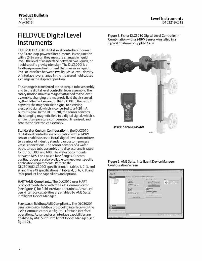
FIELDVUE Digital LevelInstrumentsFIELDVUE DLC3010 digital level controllers (figures 1and 3) are loop‐powered instruments. In conjunctionwith a 249 sensor, they measure changes in liquidlevel, the level of an interface between two liquids, orliquid specific gravity (density). The DLC3020f is afieldbus‐powered instrument that measures liquidlevel or interface between two liquids. A level, density,or interface level change in the measured fluid causesa change in the displacer position.
This change is transferred to the torque tube assemblyand to the digital level controller lever assembly. Therotary motion moves a magnet attached to the leverassembly, changing the magnetic field that is sensedby the Hall‐effect sensor. In the DLC3010, the sensorconverts the magnetic field signal to a varyingelectronic signal, which is converted to a 4‐20 mAoutput signal. In the DLC3020f, the sensor convertsthe changing magnetic field to a digital signal, which isambient temperature compensated, linearized, andsent to the electronics assembly.
Standard or Custom Configuration... the DLC3010digital level controller in combination with a 249Wsensor enables users to install digital level transmittersto a variety of industry standard or custom processvessel connections. The sensor consists of a waferbody, torque tube assembly and displacer and is ratedfor CL150, 300, and 600. The wafer body mountsbetween NPS 3 or 4 raised face flanges. Customconfigurations are also available to meet your specificapplication requirements. Refer to theDLC3010/DLC3020f specifications in tables 1, 2, 3, and9, and the 249 specifications in tables 4, 5, 6, 7, 8, and9 for product line capabilities and options.
HART/AMS Compliant... The DLC3010 uses HARTprotocol to interface with the Field Communicator(see figure 1) for field interface operations. Advanceduser‐interface capabilities are enabled by AMS Suite:Intelligent Device Manager.
FOUNDATION fieldbus/AMS Compliant... The DLC3020fuses FOUNDATION fieldbus protocol to interface with theField Communicator (see figure 1) for field interfaceoperations. Advanced user‐interface capabilities areenabled by AMS Suite: Intelligent Device Manager (seefigure 2).
Figure 1. Fisher DLC3010 Digital Level Controller inCombination with a 249W Sensor —Installed in aTypical Customer‐Supplied Cage
W8678
475 FIELD COMMUNICATOR
Figure 2. AMS Suite: Intelligent Device Manager Configuration Screen
Level InstrumentsD103219X012
Product Bulletin11.2:LevelMay 2013
3
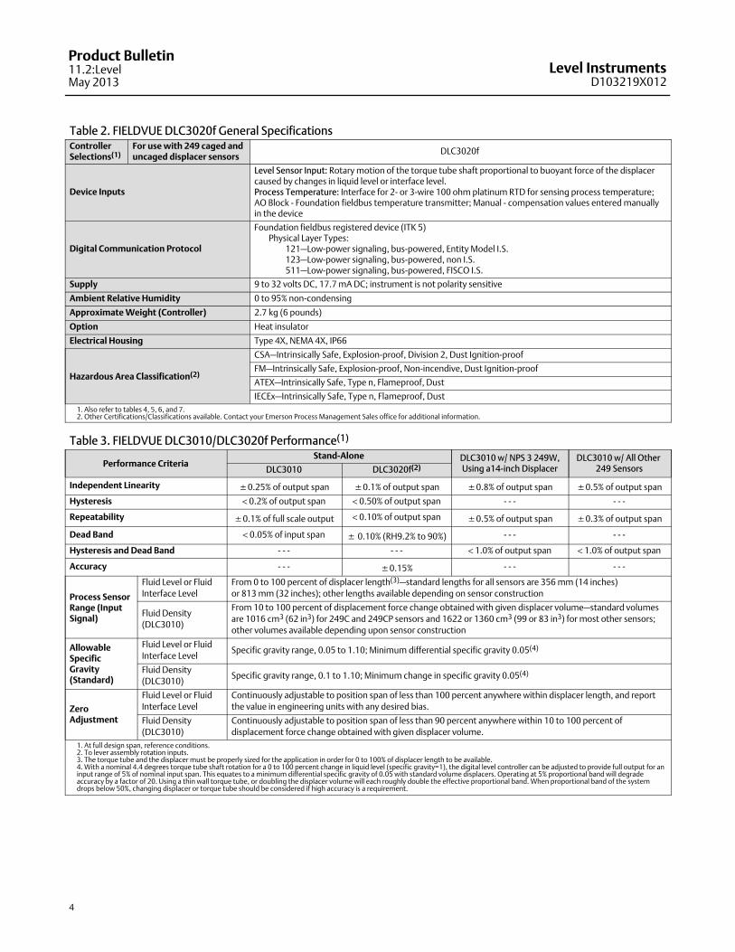
Simplified Setup and Calibration... With the electronicDevice Setup, digital level controller startup isstraightforward and fast. Level and temperaturealarms, specific gravity tables, calibration trim, andtrending are readily configurable. DLC3010/DLC3020fdigital level controllers also support re‐rangingwithout a fluid reference.
Responsive to Small Process Change... Accurate,high‐gain analog‐to‐digital conversion enablesmeasurement of small changes in the process variable.In addition, an input filter and output damping may beadjusted by the user to attenuate noise frommechanical disturbance or liquid turbulence at thedisplacer.
Easy Maintenance... Field wiring connections are in acompartment separated from the electronics. Thishelps to protect the electronics from any moisturebrought into the housing by the field wiring. This alsoeases installation and maintenance. The digital levelcontroller does not have to be removed to facilitatetroubleshooting or service. However, if it is necessaryto remove the digital level controller for in‐shopmaintenance and calibration, field wiring does notneed to be disconnected.
Figure 3. FIELDVUE DLC3020f Digital Level Controller
W6102‐1
Note
Mountings for Masoneilan, Yamatake and Foxboro/Eckhardtsensors are available. Contact your Emerson ProcessManagement sales office for mounting kit information.
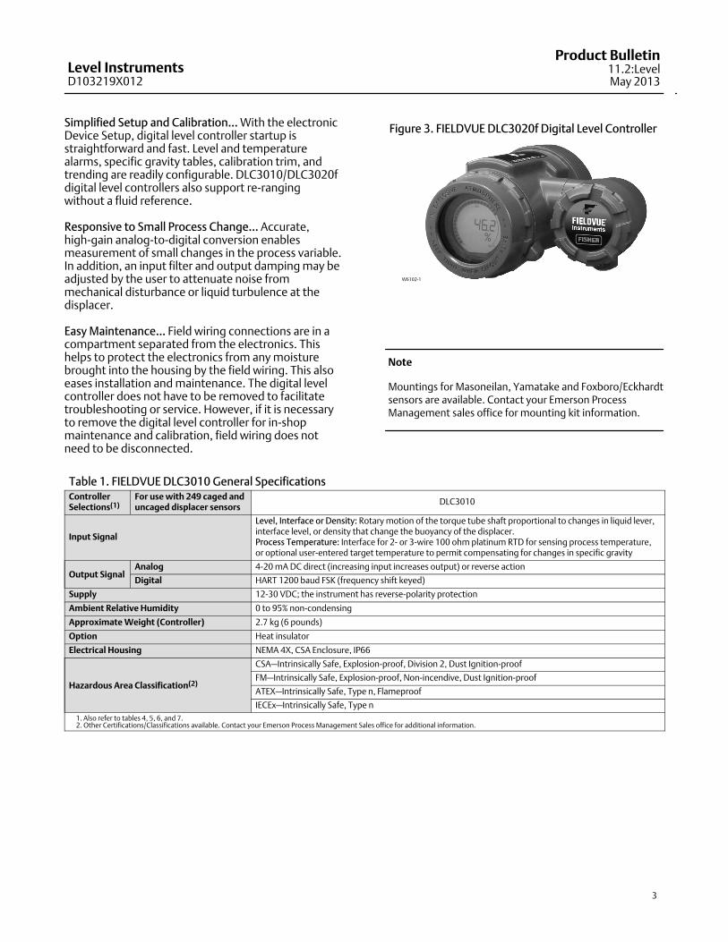
Table 1. FIELDVUE DLC3010 General SpecificationsControllerSelections(1)
For use with 249 caged anduncaged displacer sensors
DLC3010
Input Signal
Level, Interface or Density: Rotary motion of the torque tube shaft proportional to changes in liquid lever,interface level, or density that change the buoyancy of the displacer. Process Temperature: Interface for 2‐ or 3‐wire 100 ohm platinum RTD for sensing process temperature,or optional user‐entered target temperature to permit compensating for changes in specific gravity
Output SignalAnalog 4‐20 mA DC direct (increasing input increases output) or reverse action
Digital HART 1200 baud FSK (frequency shift keyed)
Supply 12‐30 VDC; the instrument has reverse‐polarity protection
Ambient Relative Humidity 0 to 95% non‐condensing
Approximate Weight (Controller) 2.7 kg (6 pounds)
Option Heat insulator
Electrical Housing NEMA 4X, CSA Enclosure, IP66
Hazardous Area Classification(2)
CSA—Intrinsically Safe, Explosion-proof, Division 2, Dust Ignition-proof
FM—Intrinsically Safe, Explosion-proof, Non-incendive, Dust Ignition-proof
ATEX—Intrinsically Safe, Type n, Flameproof
IECEx—Intrinsically Safe, Type n
1. Also refer to tables 4, 5, 6, and 7.2. Other Certifications/Classifications available. Contact your Emerson Process Management Sales office for additional information.
Level InstrumentsD103219X012
Product Bulletin11.2:LevelMay 2013
4
Table 2. FIELDVUE DLC3020f General SpecificationsControllerSelections(1)
For use with 249 caged anduncaged displacer sensors
DLC3020f
Device Inputs
Level Sensor Input: Rotary motion of the torque tube shaft proportional to buoyant force of the displacercaused by changes in liquid level or interface level. Process Temperature: Interface for 2‐ or 3‐wire 100 ohm platinum RTD for sensing process temperature;AO Block - Foundation fieldbus temperature transmitter; Manual - compensation values entered manuallyin the device
Digital Communication Protocol
Foundation fieldbus registered device (ITK 5)Physical Layer Types:
121—Low-power signaling, bus-powered, Entity Model I.S.123—Low-power signaling, bus-powered, non I.S.511—Low-power signaling, bus-powered, FISCO I.S.
Supply 9 to 32 volts DC, 17.7 mA DC; instrument is not polarity sensitive
Ambient Relative Humidity 0 to 95% non‐condensing
Approximate Weight (Controller) 2.7 kg (6 pounds)
Option Heat insulator
Electrical Housing Type 4X, NEMA 4X, IP66
Hazardous Area Classification(2)
CSA—Intrinsically Safe, Explosion-proof, Division 2, Dust Ignition-proof
FM—Intrinsically Safe, Explosion-proof, Non-incendive, Dust Ignition-proof
ATEX—Intrinsically Safe, Type n, Flameproof, Dust
IECEx—Intrinsically Safe, Type n, Flameproof, Dust
1. Also refer to tables 4, 5, 6, and 7.2. Other Certifications/Classifications available. Contact your Emerson Process Management Sales office for additional information.
Table 3. FIELDVUE DLC3010/DLC3020f Performance(1)
Performance CriteriaStand‐Alone DLC3010 w/ NPS 3 249W,
Using a14‐inch DisplacerDLC3010 w/ All Other
249 SensorsDLC3010 DLC3020f(2)
Independent Linearity �0.25% of output span �0.1% of output span �0.8% of output span �0.5% of output span
Hysteresis < 0.2% of output span < 0.50% of output span - - - - - -
Repeatability �0.1% of full scale output < 0.10% of output span �0.5% of output span �0.3% of output span
Dead Band < 0.05% of input span � 0.10% (RH9.2% to 90%) - - - - - -
Hysteresis and Dead Band - - - - - - < 1.0% of output span < 1.0% of output span
Accuracy - - - �0.15% - - - - - -
Process SensorRange (InputSignal)
Fluid Level or Fluid
Interface Level
From 0 to 100 percent of displacer length(3)—standard lengths for all sensors are 356 mm (14 inches)
or 813 mm (32 inches); other lengths available depending on sensor construction
Fluid Density
(DLC3010)
From 10 to 100 percent of displacement force change obtained with given displacer volume—standard volumes
are 1016 cm3 (62 in3) for 249C and 249CP sensors and 1622 or 1360 cm3 (99 or 83 in3) for most other sensors;
other volumes available depending upon sensor construction
AllowableSpecificGravity(Standard)
Fluid Level or Fluid
Interface LevelSpecific gravity range, 0.05 to 1.10; Minimum differential specific gravity 0.05(4)
Fluid Density
(DLC3010)Specific gravity range, 0.1 to 1.10; Minimum change in specific gravity 0.05(4)
ZeroAdjustment
Fluid Level or Fluid
Interface Level
Continuously adjustable to position span of less than 100 percent anywhere within displacer length, and report
the value in engineering units with any desired bias.
Fluid Density
(DLC3010)
Continuously adjustable to position span of less than 90 percent anywhere within 10 to 100 percent of
displacement force change obtained with given displacer volume.
1. At full design span, reference conditions.2. To lever assembly rotation inputs.3. The torque tube and the displacer must be properly sized for the application in order for 0 to 100% of displacer length to be available.4. With a nominal 4.4 degrees torque tube shaft rotation for a 0 to 100 percent change in liquid level (specific gravity=1), the digital level controller can be adjusted to provide full output for aninput range of 5% of nominal input span. This equates to a minimum differential specific gravity of 0.05 with standard volume displacers. Operating at 5% proportional band will degradeaccuracy by a factor of 20. Using a thin wall torque tube, or doubling the displacer volume will each roughly double the effective proportional band. When proportional band of the systemdrops below 50%, changing displacer or torque tube should be considered if high accuracy is a requirement.
Level InstrumentsD103219X012
Product Bulletin11.2:LevelMay 2013
5
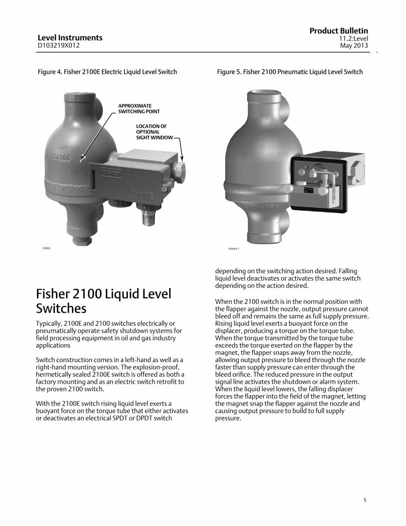
Figure 4. Fisher 2100E Electric Liquid Level Switch
APPROXIMATE SWITCHING POINT
LOCATION OFOPTIONALSIGHT WINDOW
X0682
Fisher 2100 Liquid LevelSwitchesTypically, 2100E and 2100 switches electrically orpneumatically operate safety shutdown systems forfield processing equipment in oil and gas industryapplications
Switch construction comes in a left‐hand as well as aright‐hand mounting version. The explosion‐proof,hermetically sealed 2100E switch is offered as both afactory mounting and as an electric switch retrofit tothe proven 2100 switch.
With the 2100E switch rising liquid level exerts abuoyant force on the torque tube that either activatesor deactivates an electrical SPDT or DPDT switch
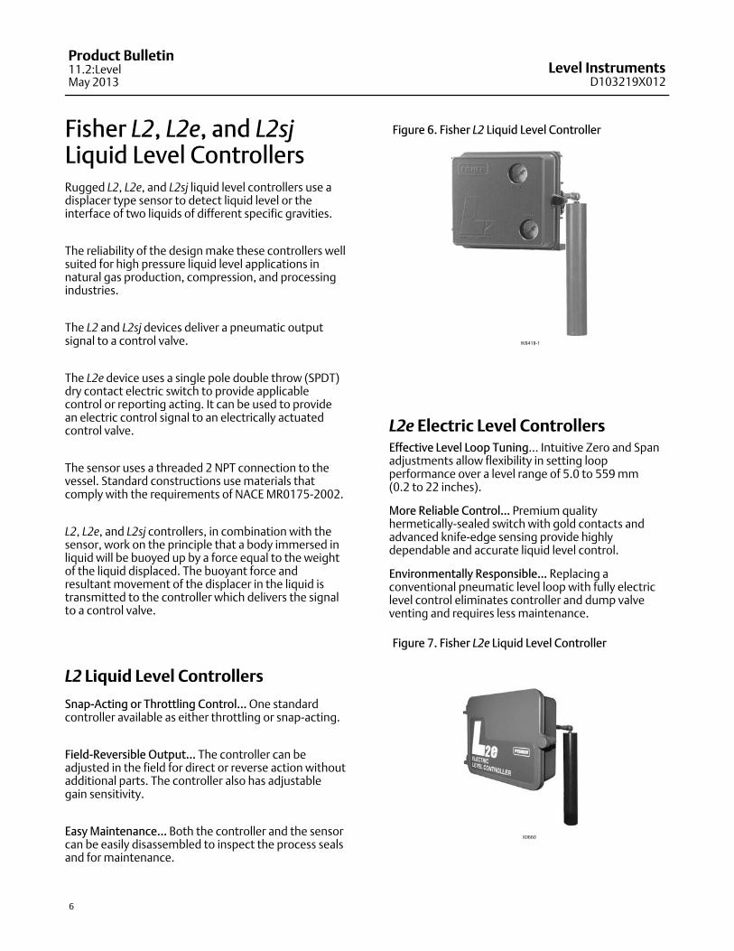
Figure 5. Fisher 2100 Pneumatic Liquid Level Switch
W9954-1
depending on the switching action desired. Fallingliquid level deactivates or activates the same switchdepending on the action desired.
When the 2100 switch is in the normal position withthe flapper against the nozzle, output pressure cannotbleed off and remains the same as full supply pressure.Rising liquid level exerts a buoyant force on thedisplacer, producing a torque on the torque tube.When the torque transmitted by the torque tubeexceeds the torque exerted on the flapper by themagnet, the flapper snaps away from the nozzle,allowing output pressure to bleed through the nozzlefaster than supply pressure can enter through thebleed orifice. The reduced pressure in the outputsignal line activates the shutdown or alarm system.When the liquid level lowers, the falling displacerforces the flapper into the field of the magnet, lettingthe magnet snap the flapper against the nozzle andcausing output pressure to build to full supplypressure.
Level InstrumentsD103219X012
Product Bulletin11.2:LevelMay 2013
6
Fisher L2, L2e, and L2sjLiquid Level ControllersRugged L2, L2e, and L2sj liquid level controllers use adisplacer type sensor to detect liquid level or theinterface of two liquids of different specific gravities.
The reliability of the design make these controllers wellsuited for high pressure liquid level applications innatural gas production, compression, and processingindustries.
The L2 and L2sj devices deliver a pneumatic outputsignal to a control valve.
The L2e device uses a single pole double throw (SPDT)dry contact electric switch to provide applicablecontrol or reporting acting. It can be used to providean electric control signal to an electrically actuatedcontrol valve.
The sensor uses a threaded 2 NPT connection to thevessel. Standard constructions use materials thatcomply with the requirements of NACE MR0175‐2002.
L2, L2e, and L2sj controllers, in combination with thesensor, work on the principle that a body immersed inliquid will be buoyed up by a force equal to the weightof the liquid displaced. The buoyant force andresultant movement of the displacer in the liquid istransmitted to the controller which delivers the signalto a control valve.
L2 Liquid Level Controllers
Snap‐Acting or Throttling Control... One standardcontroller available as either throttling or snap‐acting.
Field‐Reversible Output... The controller can beadjusted in the field for direct or reverse action withoutadditional parts. The controller also has adjustablegain sensitivity.
Easy Maintenance... Both the controller and the sensorcan be easily disassembled to inspect the process sealsand for maintenance.
Figure 6. Fisher L2 Liquid Level Controller
W8418‐1
L2e Electric Level ControllersEffective Level Loop Tuning… Intuitive Zero and Spanadjustments allow flexibility in setting loopperformance over a level range of 5.0 to 559 mm (0.2 to 22 inches).
More Reliable Control… Premium qualityhermetically-sealed switch with gold contacts andadvanced knife-edge sensing provide highlydependable and accurate liquid level control.
Environmentally Responsible… Replacing aconventional pneumatic level loop with fully electriclevel control eliminates controller and dump valveventing and requires less maintenance.
Figure 7. Fisher L2e Liquid Level Controller
X0660
Level InstrumentsD103219X012
Product Bulletin11.2:LevelMay 2013
7
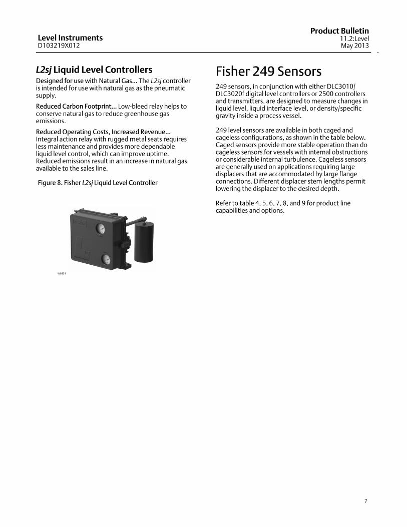
L2sj Liquid Level ControllersDesigned for use with Natural Gas... The L2sj controlleris intended for use with natural gas as the pneumaticsupply.
Reduced Carbon Footprint... Low‐bleed relay helps toconserve natural gas to reduce greenhouse gasemissions.
Reduced Operating Costs, Increased Revenue...Integral action relay with rugged metal seats requiresless maintenance and provides more dependableliquid level control, which can improve uptime.Reduced emissions result in an increase in natural gasavailable to the sales line.
Figure 8. Fisher L2sj Liquid Level Controller
W9331
Fisher 249 Sensors249 sensors, in conjunction with either DLC3010/DLC3020f digital level controllers or 2500 controllersand transmitters, are designed to measure changes inliquid level, liquid interface level, or density/specificgravity inside a process vessel.
249 level sensors are available in both caged andcageless configurations, as shown in the table below.Caged sensors provide more stable operation than docageless sensors for vessels with internal obstructionsor considerable internal turbulence. Cageless sensorsare generally used on applications requiring largedisplacers that are accommodated by large flangeconnections. Different displacer stem lengths permitlowering the displacer to the desired depth.
Refer to table 4, 5, 6, 7, 8, and 9 for product linecapabilities and options.
Level InstrumentsD103219X012
Product Bulletin11.2:LevelMay 2013
8
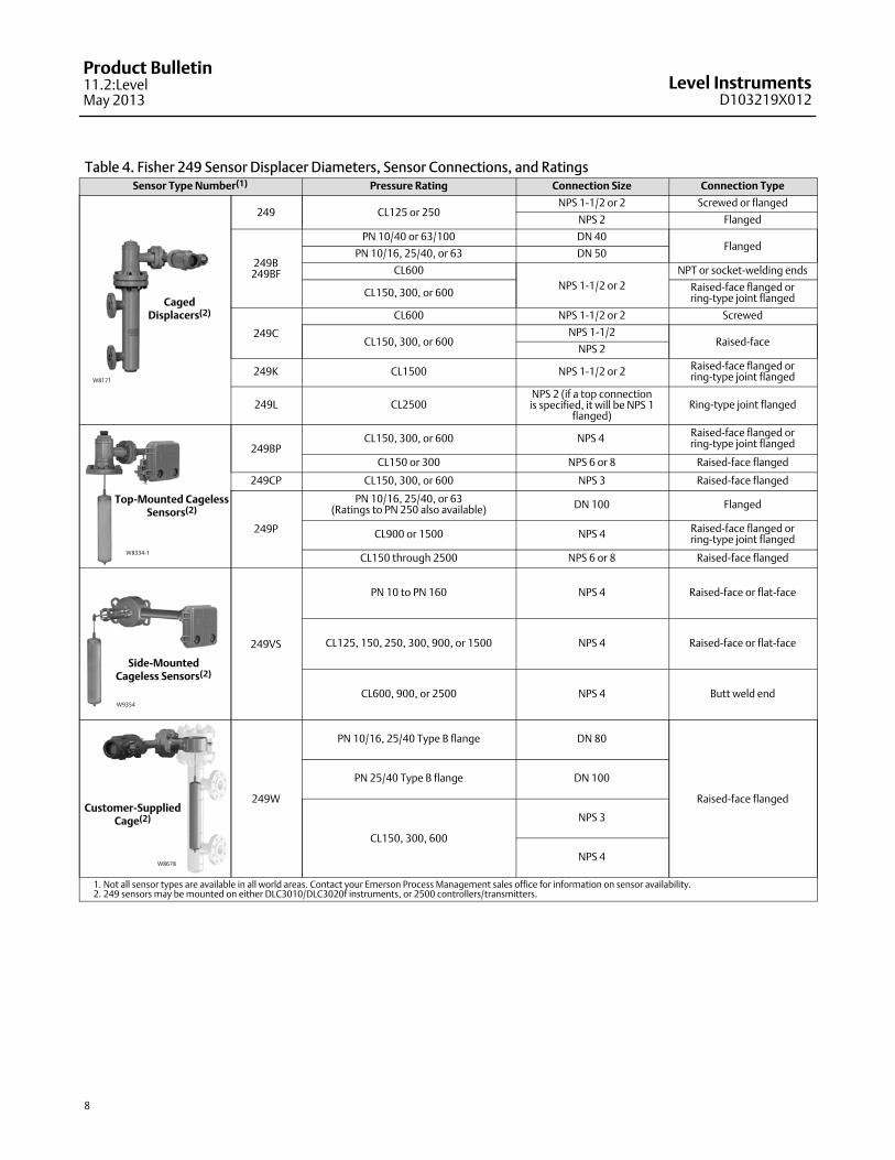
Table 4. Fisher 249 Sensor Displacer Diameters, Sensor Connections, and RatingsSensor Type Number(1) Pressure Rating Connection Size Connection Type
CagedDisplacers(2)
W8171
249 CL125 or 250NPS 1‐1/2 or 2 Screwed or flanged
NPS 2 Flanged
249B249BF
PN 10/40 or 63/100 DN 40Flanged
PN 10/16, 25/40, or 63 DN 50
CL600
NPS 1‐1/2 or 2
NPT or socket‐welding ends
CL150, 300, or 600Raised‐face flanged orring‐type joint flanged
249C
CL600 NPS 1‐1/2 or 2 Screwed
CL150, 300, or 600NPS 1‐1/2
Raised‐faceNPS 2
249K CL1500 NPS 1‐1/2 or 2Raised‐face flanged orring‐type joint flanged
249L CL2500NPS 2 (if a top connectionis specified, it will be NPS 1
flanged)Ring‐type joint flanged
Top‐Mounted CagelessSensors(2)
W8334‐1
249BPCL150, 300, or 600 NPS 4
Raised‐face flanged orring‐type joint flanged
CL150 or 300 NPS 6 or 8 Raised‐face flanged
249CP CL150, 300, or 600 NPS 3 Raised‐face flanged
249P
PN 10/16, 25/40, or 63(Ratings to PN 250 also available) DN 100 Flanged
CL900 or 1500 NPS 4Raised‐face flanged orring‐type joint flanged
CL150 through 2500 NPS 6 or 8 Raised‐face flanged
Side‐MountedCageless Sensors(2)
W9354
249VS
PN 10 to PN 160 NPS 4 Raised‐face or flat‐face
CL125, 150, 250, 300, 900, or 1500 NPS 4 Raised‐face or flat‐face
CL600, 900, or 2500 NPS 4 Butt weld end
Customer‐SuppliedCage(2)
W8678
249W
PN 10/16, 25/40 Type B flange DN 80
Raised‐face flanged
PN 25/40 Type B flange DN 100
CL150, 300, 600
NPS 3
NPS 4
1. Not all sensor types are available in all world areas. Contact your Emerson Process Management sales office for information on sensor availability.2. 249 sensors may be mounted on either DLC3010/DLC3020f instruments, or 2500 controllers/transmitters.
Level InstrumentsD103219X012
Product Bulletin11.2:LevelMay 2013
9
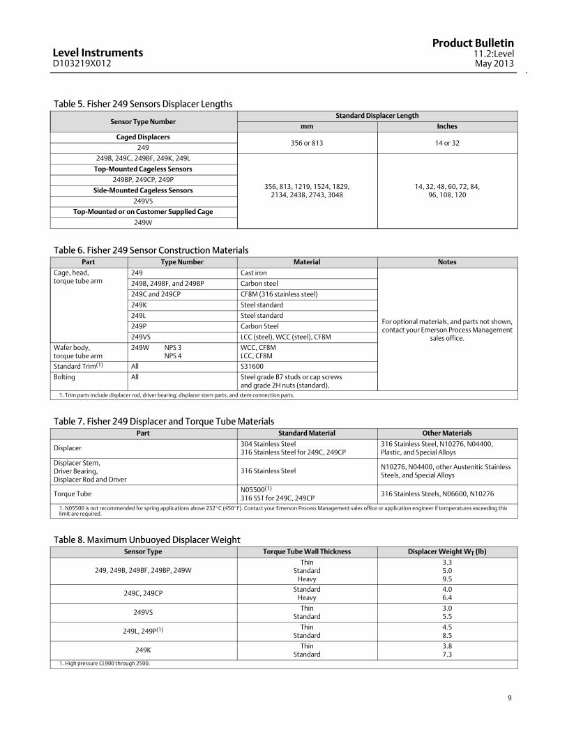
Table 5. Fisher 249 Sensors Displacer Lengths
Sensor Type NumberStandard Displacer Length
mm Inches
Caged Displacers356 or 813 14 or 32
249
249B, 249C, 249BF, 249K, 249L
356, 813, 1219, 1524, 1829,2134, 2438, 2743, 3048
14, 32, 48, 60, 72, 84,96, 108, 120
Top‐Mounted Cageless Sensors
249BP, 249CP, 249P
Side‐Mounted Cageless Sensors
249VS
Top‐Mounted or on Customer Supplied Cage
249W
Table 6. Fisher 249 Sensor Construction MaterialsPart Type Number Material Notes
Cage, head,torque tube arm
249 Cast iron
For optional materials, and parts not shown,contact your Emerson Process Management
sales office.
249B, 249BF, and 249BP Carbon steel
249C and 249CP CF8M (316 stainless steel)
249K Steel standard
249L Steel standard
249P Carbon Steel
249VS LCC (steel), WCC (steel), CF8M
Wafer body,torque tube arm
249W NPS 3NPS 4
WCC, CF8MLCC, CF8M
Standard Trim(1) All S31600
Bolting All Steel grade B7 studs or cap screws and grade 2H nuts (standard),
1. Trim parts include displacer rod, driver bearing; displacer stem parts, and stem connection parts.
Table 7. Fisher 249 Displacer and Torque Tube MaterialsPart Standard Material Other Materials
Displacer304 Stainless Steel316 Stainless Steel for 249C, 249CP
316 Stainless Steel, N10276, N04400,Plastic, and Special Alloys
Displacer Stem,Driver Bearing,Displacer Rod and Driver
316 Stainless SteelN10276, N04400, other Austenitic StainlessSteels, and Special Alloys
Torque TubeN05500(1)
316 SST for 249C, 249CP316 Stainless Steels, N06600, N10276
1. N05500 is not recommended for spring applications above 232�C (450�F). Contact your Emerson Process Management sales office or application engineer if temperatures exceeding thislimit are required.
Table 8. Maximum Unbuoyed Displacer WeightSensor Type Torque Tube Wall Thickness Displacer Weight WT (lb)
249, 249B, 249BF, 249BP, 249WThin
StandardHeavy
3.35.09.5
249C, 249CPStandard
Heavy4.06.4
249VSThin
Standard3.05.5
249L, 249P(1) ThinStandard
4.58.5
249KThin
Standard3.87.3
1. High pressure CL900 through 2500.
Level InstrumentsD103219X012
Product Bulletin11.2:LevelMay 2013
10
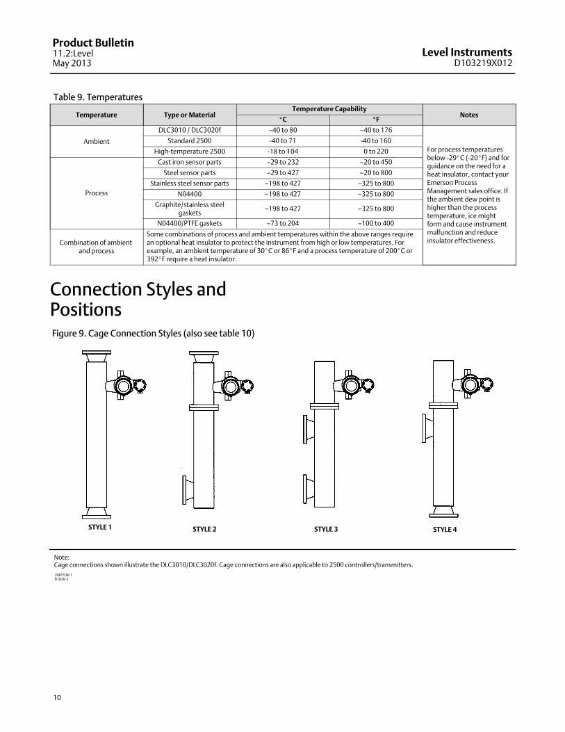
Table 9. Temperatures
Temperature Type or MaterialTemperature Capability
Notes�C �F
Ambient
DLC3010 / DLC3020f –40 to 80 –40 to 176
For process temperaturesbelow -29�C (-20�F) and forguidance on the need for aheat insulator, contact yourEmerson ProcessManagement sales office. Ifthe ambient dew point ishigher than the processtemperature, ice mightform and cause instrumentmalfunction and reduceinsulator effectiveness.
Standard 2500 -40 to 71 -40 to 160
High‐temperature 2500 -18 to 104 0 to 220
Process
Cast iron sensor parts –29 to 232 –20 to 450
Steel sensor parts –29 to 427 –20 to 800
Stainless steel sensor parts –198 to 427 –325 to 800
N04400 –198 to 427 –325 to 800
Graphite/stainless steelgaskets
–198 to 427 –325 to 800
N04400/PTFE gaskets –73 to 204 –100 to 400
Combination of ambient and process
Some combinations of process and ambient temperatures within the above ranges requirean optional heat insulator to protect the instrument from high or low temperatures. Forexample, an ambient temperature of 30�C or 86�F and a process temperature of 200�C or392�F require a heat insulator.
Connection Styles andPositionsFigure 9. Cage Connection Styles (also see table 10)
STYLE 1 STYLE 2 STYLE 3 STYLE 4
28B5536‐1B1820‐2
Note:Cage connections shown illustrate the DLC3010/DLC3020f. Cage connections are also applicable to 2500 controllers/transmitters.
Level InstrumentsD103219X012
Product Bulletin11.2:LevelMay 2013
11
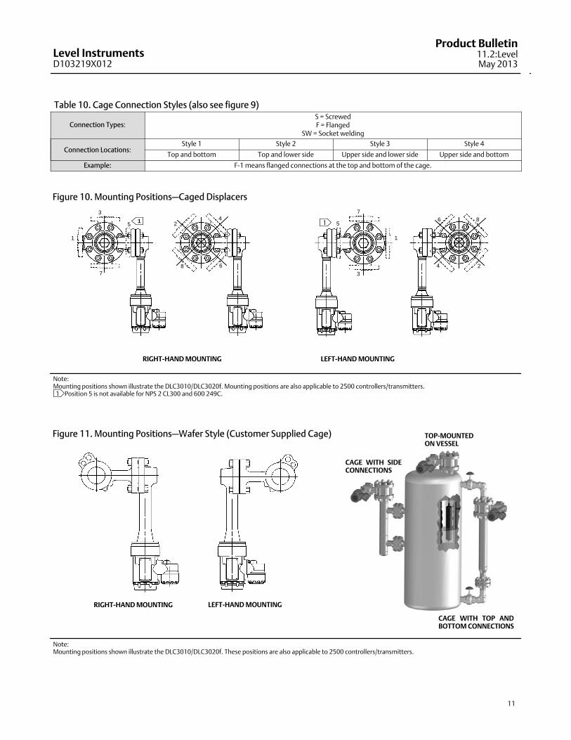
Table 10. Cage Connection Styles (also see figure 9)
Connection Types:S = ScrewedF = Flanged
SW = Socket welding
Connection Locations:Style 1 Style 2 Style 3 Style 4
Top and bottom Top and lower side Upper side and lower side Upper side and bottom
Example: F‐1 means flanged connections at the top and bottom of the cage.
Figure 10. Mounting Positions—Caged Displacers
8
24
6
3
7
1
5 11 8
24
6
1
3
7
5
RIGHT‐HAND MOUNTING LEFT‐HAND MOUNTING
Note:Mounting positions shown illustrate the DLC3010/DLC3020f. Mounting positions are also applicable to 2500 controllers/transmitters. 1 Position 5 is not available for NPS 2 CL300 and 600 249C.
Figure 11. Mounting Positions—Wafer Style (Customer Supplied Cage)
CAGE WITH SIDECONNECTIONS
TOP‐MOUNTEDON VESSEL
CAGE WITH TOP ANDBOTTOM CONNECTIONS
RIGHT‐HAND MOUNTING LEFT‐HAND MOUNTING
Note:Mounting positions shown illustrate the DLC3010/DLC3020f. These positions are also applicable to 2500 controllers/transmitters.
Level InstrumentsD103219X012
Product Bulletin11.2:LevelMay 2013
12
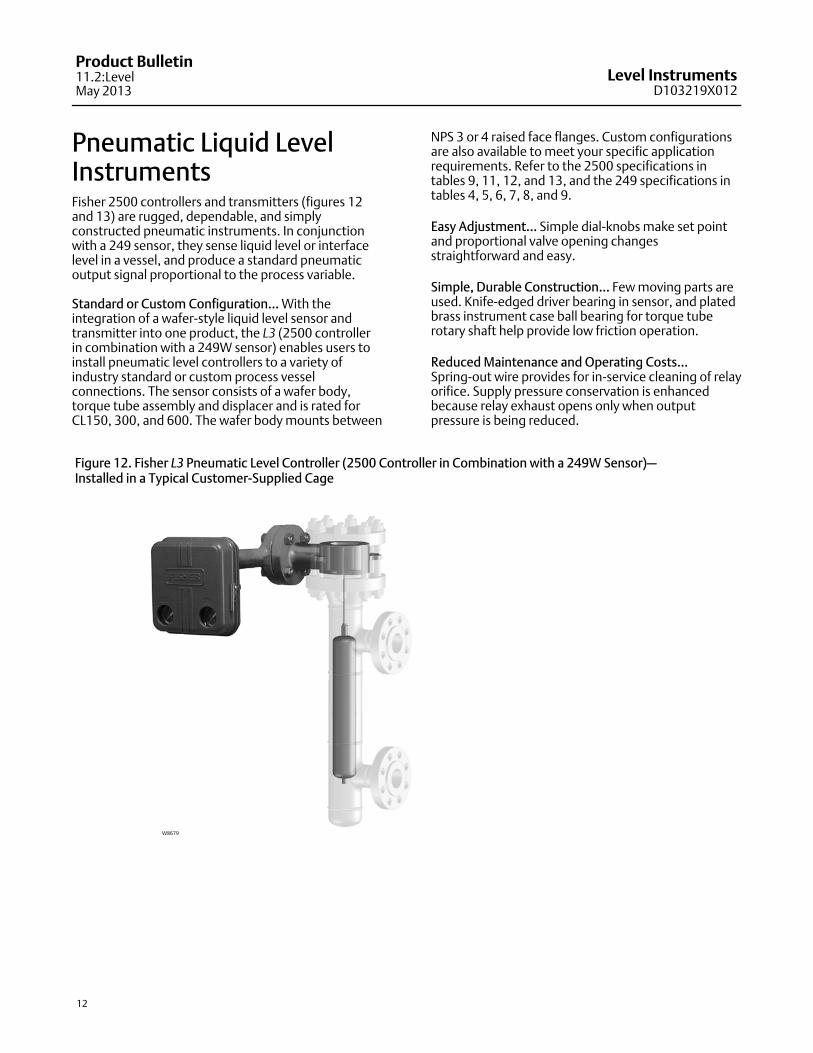
Pneumatic Liquid LevelInstrumentsFisher 2500 controllers and transmitters (figures 12and 13) are rugged, dependable, and simplyconstructed pneumatic instruments. In conjunctionwith a 249 sensor, they sense liquid level or interfacelevel in a vessel, and produce a standard pneumaticoutput signal proportional to the process variable.
Standard or Custom Configuration... With theintegration of a wafer‐style liquid level sensor andtransmitter into one product, the L3 (2500 controllerin combination with a 249W sensor) enables users toinstall pneumatic level controllers to a variety ofindustry standard or custom process vesselconnections. The sensor consists of a wafer body,torque tube assembly and displacer and is rated forCL150, 300, and 600. The wafer body mounts between
NPS 3 or 4 raised face flanges. Custom configurationsare also available to meet your specific applicationrequirements. Refer to the 2500 specifications intables 9, 11, 12, and 13, and the 249 specifications intables 4, 5, 6, 7, 8, and 9.
Easy Adjustment... Simple dial‐knobs make set pointand proportional valve opening changesstraightforward and easy.
Simple, Durable Construction... Few moving parts areused. Knife‐edged driver bearing in sensor, and platedbrass instrument case ball bearing for torque tuberotary shaft help provide low friction operation.
Reduced Maintenance and Operating Costs...Spring‐out wire provides for in‐service cleaning of relayorifice. Supply pressure conservation is enhancedbecause relay exhaust opens only when outputpressure is being reduced.
Figure 12. Fisher L3 Pneumatic Level Controller (2500 Controller in Combination with a 249W Sensor)—Installed in a Typical Customer‐Supplied Cage
W8679
Level InstrumentsD103219X012
Product Bulletin11.2:LevelMay 2013
13
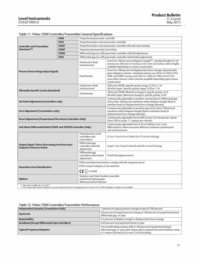
Table 11. Fisher 2500 Controller/Transmitter General Specifications
Controller and TransmitterSelections(1)
2500 Proportional pneumatic controller
2502 Proportional‐plus‐reset pneumatic controller
2502F Proportional‐plus reset pneumatic controller with anti‐reset windup
2500T Proportional pneumatic transmitter
2500S Differential gap (on‐off) pneumatic controller with full adjustment
2503 Differential gap (on‐off) pneumatic controller with limited adjustment
Process Sensor Range (Input Signal)
Fluid level or fluidinterface level
From 0 to 100 percent of displacer length(2)—standard lengths for allsensors are 356 mm (14 inches) or 813 mm (32 inches); other lengthsavailable depending on sensor construction
Fluid density
From 0 to 100 percent of displacement force change obtained withgiven displacer volume—standard volumes are 1016 cm3 (62 in3) for249C and 249CP sensors and 1622 or 1360 cm3 (99 or 83 in3) formost other sensors; other volumes available depending upon sensorconstruction
Allowable Specific Gravity (Standard)
Fluid level or fluidinterface level
2503 and 2503R: Specific gravity range, 0.25 to 1.10All other types: Specific gravity range, 0.20 to 1.10
Fluid density2503 and 2503R: Minimum change in specific gravity, 0.25All other types: Minimum change in specific gravity, 0.20
Set Point Adjustment (Controllers only)Continuously adjustable to position control point or differential gap of less than 100 percent anywhere within displacer length (fluid orinterface level) or displacement force change (density)
Zero Adjustment (Transmitters only)Continuously adjustable to position span of less than 100 percentanywhere within displacer length (fluid or interface level) ordisplacement force change (density)
Reset Adjustment (Proportional‐Plus‐Reset Controllers Only)Continuously adjustable from 0.005 to over 0.9 minutes per repeat(from 200 to under 1.1 repeats per minute)
Anti‐Reset Differential Relief (2502F and 2502FR Controllers Only)Continuously adjustable from 0.14 to 0.48 bar (2 to 7 psi) differential to relieve excessive difference between proportional and reset pressures
Output Signal‐‐Direct (Increasing Level IncreasesOutput) or Reverse Action
Proportional or resetcontrollers andtransmitters
0.2 to 1.0 or 0.4 to 2.0 bar (3 to 15 or 6 to 30 psig)
Differential gapcontrollers with fulladjustment
0 and 1.4 or 0 and 2.4 bar (0 and 20 or 0 and 35 psig)
Differential gapcontrollers with limitedadjustment
0 and full supply pressure
Hazardous Area Classification
2500 controllers/transmitters comply with the requirements of
ATEX Group II Category 2 Gas and Dust
OptionsStainless steel heat insulator assemblyLiquid level sight gaugesMechanical level indicator
1. Also refer to tables 4, 5, 6, and 7.2. The torque tube and the displacer must be properly sized for the application in order for 0 to 100% of displacer length to be available.
Table 12. Fisher 2500 Controller/Transmitter PerformanceIndependent Linearity (Transmitters Only) 1 percent of output pressure change at span of 100 percent
Hysteresis0.6 percent of output pressure change at 100 percent of proportional band,differential gap, or span
Repeatability 0.2 percent of displacer length or displacement force change
Deadband (Except Differential Gap Controllers) 0.05 percent of proportional band or span
Typical Frequency Response4 Hz and 90‐degree phase shift at 100 percent of proportional band,diferential gap, or span with output pipe to typical instrument bellows using6.1 meters (20 feet) of 6.3 mm (1/4‐inch) tubing
Level InstrumentsD103219X012
Product Bulletin11.2:LevelMay 2013
14
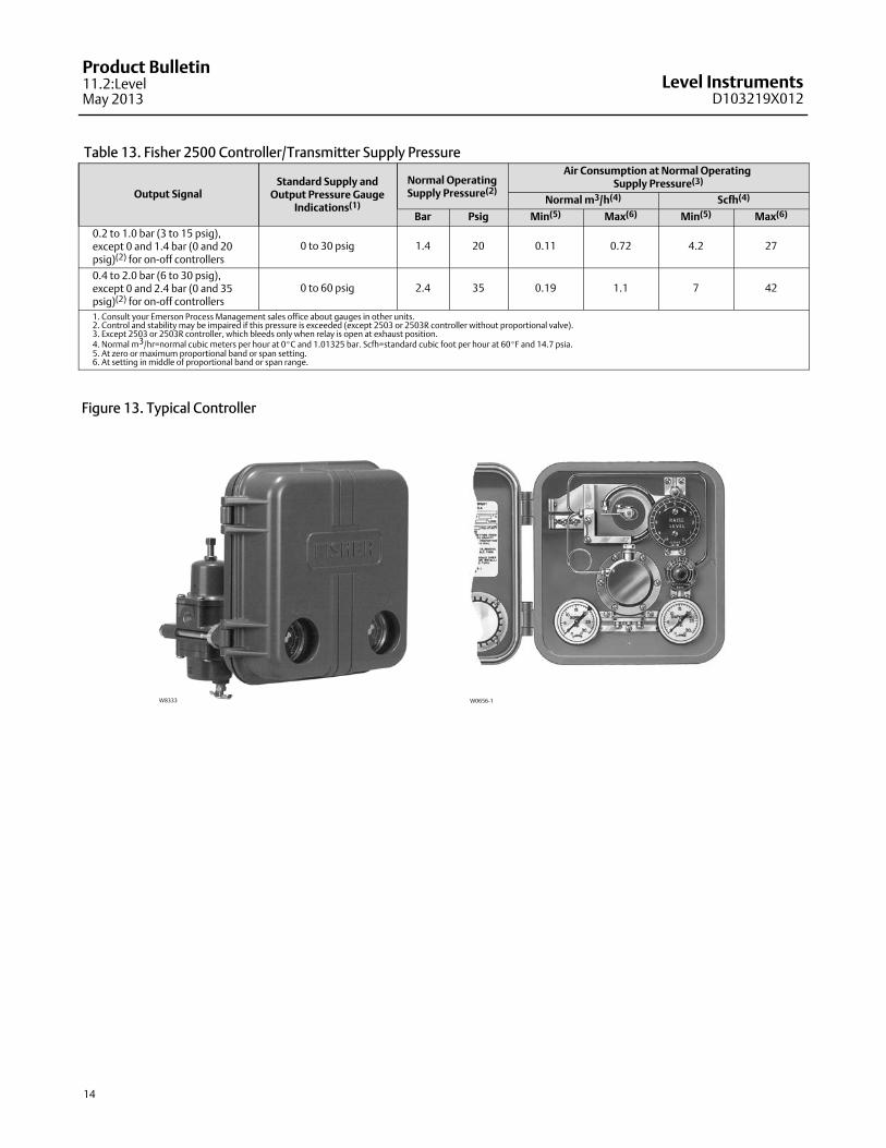
Table 13. Fisher 2500 Controller/Transmitter Supply Pressure
Output SignalStandard Supply and
Output Pressure GaugeIndications(1)
Normal OperatingSupply Pressure(2)
Air Consumption at Normal Operating Supply Pressure(3)
Normal m3/h(4) Scfh(4)
Bar Psig Min(5) Max(6) Min(5) Max(6)
0.2 to 1.0 bar (3 to 15 psig),except 0 and 1.4 bar (0 and 20psig)(2) for on‐off controllers
0 to 30 psig 1.4 20 0.11 0.72 4.2 27
0.4 to 2.0 bar (6 to 30 psig),except 0 and 2.4 bar (0 and 35psig)(2) for on‐off controllers
0 to 60 psig 2.4 35 0.19 1.1 7 42
1. Consult your Emerson Process Management sales office about gauges in other units.2. Control and stability may be impaired if this pressure is exceeded (except 2503 or 2503R controller without proportional valve).3. Except 2503 or 2503R controller, which bleeds only when relay is open at exhaust position.4. Normal m3/hr=normal cubic meters per hour at 0�C and 1.01325 bar. Scfh=standard cubic foot per hour at 60�F and 14.7 psia.5. At zero or maximum proportional band or span setting.6. At setting in middle of proportional band or span range.
Figure 13. Typical Controller
W0656‐1W8333
Level InstrumentsD103219X012
Product Bulletin11.2:LevelMay 2013
15
Related DocumentsOther documents containing information related tolevel instruments include:
� FIELDVUE DLC3010 Digital Level Controller (Bulletin 11.2:DLC3010) (D102727X012)
� FIELDVUE DLC3020f Digital Level Controller(Bulletin 11.2:DLC3020f) (D103433X012)
� Fisher 2100 Pneumatic and 2100E Electric LiquidLevel Switches (Bulletin 32.2:2100) (D200032X012)
� Fisher DL3 Digital Level Controller (Bulletin 11.2:DL3) (D103193X012)
� Fisher L3 Pneumatic Level Controller (Bulletin 34.2:L3) (D103194X012)
� Fisher L2 Liquid Level Controller (Bulletin 34.2:L2) (D103034X012)
� Fisher L2e Electric Level Controller (Bulletin 34.2:L2e) (D103532X012)
� Fisher L2sj Liquid Level Controller(Bulletin 34.2:L2sj) (D103229X012)
� Fisher 2500‐249 Pneumatic Controllers andTransmitters (Bulletin 34.2:2500) (D200037X012)
These documents are available from your EmersonProcess Management sales office. Also visit ourwebsite at www.Fisher.com.
Level InstrumentsD103219X012
Product Bulletin11.2:LevelMay 2013
16
Emerson Process Management Marshalltown, Iowa 50158 USASorocaba, 18087 BrazilChatham, Kent ME4 4QZ UKDubai, United Arab EmiratesSingapore 128461 Singapore
www.Fisher.com
The contents of this publication are presented for informational purposes only, and while every effort has been made to ensure their accuracy, they are notto be construed as warranties or guarantees, express or implied, regarding the products or services described herein or their use or applicability. All sales aregoverned by our terms and conditions, which are available upon request. We reserve the right to modify or improve the designs or specifications of suchproducts at any time without notice.
� 2005, 2013 Fisher Controls International LLC. All rights reserved.
Fisher and FIELDVUE are marks owned by one of the companies in the Emerson Process Management business unit of Emerson Electric Co. Emerson ProcessManagement, Emerson, and the Emerson logo are trademarks and service marks of Emerson Electric Co. All other marks are the property of their respectiveowners.
Neither Emerson, Emerson Process Management, nor any of their affiliated entities assumes responsibility for the selection, use or maintenanceof any product. Responsibility for proper selection, use, and maintenance of any product remains solely with the purchaser and end user.