federico piscaglia slides
TRANSCRIPT

Develpment of NSCBC for compressible
Navier-Stokes equations in OpenFOAM®:
Subsonic Non-Reflecting Outflow
F. Piscaglia, A. MontorfanoDipartimento di Energia, POLITECNICO DI MILANO
http://www.engines.polimi.it

Content
Introduction
Theory
- The NSCBC strategy for Navier-Stokes equations
- The Local One Dimensional Inviscid (LODI) relations
- Subsonic Non-Reflecting Outflow
- Unsteady flows and numerical waves control
- Shock-tube: test
Application: non linear acoustic simulation of silencers
- Reverse flow chambers
- Single-plug perforated muffler
Conclusions
http://www.engines.polimi.it

Introduction
An ideal muffler for a ICE should work as a low pass filter: attenuation should be applied tothe fluctuating flow which is associated with the acoustic pressure fluctuation, while the steadyor mean flow should be allowed to pass unimpeded through the muffler.
- The performance of a silencer can be described by two key parameters:
- the attenuation of the pressure fluctuations crossing the muffler over a pre-definedwide frequency range, usually 20-2000 Hz
- the pressure drop associated with convective and dissipative effects of the mean flow:it affects both the acoustic attenuation performance and the “back pressure” seen by theengine
http://www.engines.polimi.it
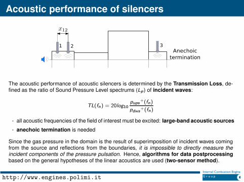
Acoustic performance of silencers
The acoustic performance of acoustic silencers is determined by the Transmission Loss, de-fined as the ratio of Sound Pressure Level spectrums (Lp ) of incident waves:
TL(fn) = 20log10
pups+(fn)
pdws+(fn)
- all acoustic frequencies of the field of interest must be excited: large-band acoustic sources
- anechoic termination is needed
Since the gas pressure in the domain is the result of superimposition of incident waves comingfrom the source and reflections from the boundaries, it is impossible to directly measure theincident components of the pressure pulsation. Hence, algorithms for data postprocessingbased on the general hypotheses of the linear acoustics are used (two-sensor method).
http://www.engines.polimi.it

Motivation
The objective of this study is:
- to develop a three-dimensional time-domain approach based on the CFD simulation to eval-uate the transmission loss of silencers and resonators without and with mean flow
- to examine the influence of mean flow on the acoustic attenuation performance of complexsilencers
... but:
- an inlet b.c. to model different acoustic sources is needed
- acoustic simulations of compressible flows require an accurate control of wave reflec-tions from the computational domain boundaries. Acoustic waves are often modified bynumerical dissipation
- the waveTransmisive b.c. in OpenFOAM® is not perfectly non reflecting; small acousticwaves are reflected to the inner domain
- there is the need for sophisticated boundary conditions (NSCBC), which can handlecorrectly the transmission and the reflection of acoustic waves on boundaries
http://www.engines.polimi.it

acousticSourceFvPatchField
A boundary condition acousticSourceFvPatchField to model different types of acousticsources has been developed in the OpenFOAM® technology.
SINGLE SINUSOID PULSE WHITE NOISE FREQUENCY SWEEP
0 0.02 0.04 0.06 0.08 0.1101.26
101.28
101.3
101.32
101.34
101.36
101.38
101.4
time [s]
Pre
ssu
re [
kP
a]
0 0.02 0.04 0.06 0.08 0.1101.2
101.4
101.6
101.8
102
101.2
101.4
101.6
101.8
time [s]
Pre
ssu
re [
kP
a]
0 0.02 0.04 0.06 0.08 0.1101.15
101.2
101.25
101.3
101.35
101.4
time [s]
Pre
ssu
re [
kP
a]
0 0.02 0.04 0.06 0.08 0.1101.26
101.28
101.3
101.32
101.34
101.36
101.38
101.4
time [s]
Pre
ssu
re [
kP
a]
inlet
{
type acousticSourceTotalPressure;
sourceType "whiteNoise";
U U;
phi phi;
rho rho;
psi none;
gamma 1.4;
refPressure 100000;
f0 10;
fn 2000;
step 10;
amplitude 50;
value uniform 100000;
}
Different kind of time-varying per-turbations are applied at the inletboundary patch
Ad-hoc developed run time controlsensure correct case setup and avoidaliasing due to poor frequency reso-lution or to non physical frequencysignals distorting the spectrum in thechosen range (Oppenheim and Schaf-fer)
http://www.engines.polimi.it
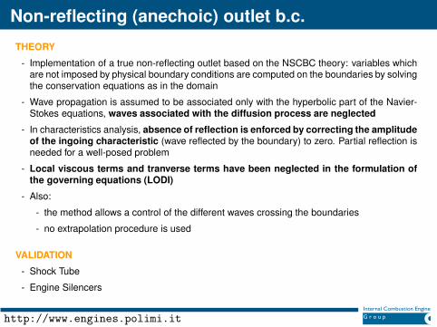
Non-reflecting (anechoic) outlet b.c.
THEORY
- Implementation of a true non-reflecting outlet based on the NSCBC theory: variables whichare not imposed by physical boundary conditions are computed on the boundaries by solvingthe conservation equations as in the domain
- Wave propagation is assumed to be associated only with the hyperbolic part of the Navier-Stokes equations, waves associated with the diffusion process are neglected
- In characteristics analysis, absence of reflection is enforced by correcting the amplitudeof the ingoing characteristic (wave reflected by the boundary) to zero. Partial reflection isneeded for a well-posed problem
- Local viscous terms and tranverse terms have been neglected in the formulation ofthe governing equations (LODI)
- Also:
- the method allows a control of the different waves crossing the boundaries
- no extrapolation procedure is used
VALIDATION
- Shock Tube
- Engine Silencers
http://www.engines.polimi.it

Non-reflecting (anechoic) outlet b.c.
For each cell face at the boundary end, the governing equations written in a local referenceframe (ξ, η, ζ) are:
Continuity:
∂ρ
∂t+ d1 +
∂ρu2
∂η+
∂ρu3
∂ζ= 0
Momentum:
∂ρu1
∂t+ u1d1 + ρd3 +
∂ρu1u2
∂η+
∂ρu1u3
∂ζ= 0
∂ρu2
∂t+ u2d1 + ρd4 +
∂ρu2u2
∂η+
∂ρu2u3
∂ζ= −
∂p
∂η
∂ρu3
∂t+ u3d1 + ρd5 +
∂ρu3u2
∂η+
∂ρu3u3
∂ζ= −
∂p
∂ζ
x
y
z
Each reference frame has its origin in the cell face center and the
vector ζ is set as perpendicular to the cell face.
Energy:
∂ρE
∂t+
1
2(uk · uk )d1 +
d2
γ − 1+ ρu1d3 + ρu2d4 + ρu3d5 +
∂[(ρE + p)u2 ]
∂η+
∂[(ρE + p)u3]
∂ζ= −∇ · q
http://www.engines.polimi.it

Extension to local Cartesian coordinates
- For each cell face at the boundary end, a local reference frame (ξ, η, ζ) has been defined:
x = x(ξ, η, ζ)
y = y(ξ, η, ζ)
z = z(ξ, η, ζ)
- Each reference frame has its origin in the cell face center and the vector ζ is set as perpen-dicular to the cell face.
- The governing equations for the global reference frame take the form:
∂U
∂t+
∂F 1
∂x+
∂F2
∂y+
∂F3
∂z= −∇pwhere
U =U
J
∂F1
∂x=
F1xξ + F 2xη + F 3xζ
J
∂F2
∂y=
F1yξ + F 2yη + F 3yζ
J
∂F3
∂z=
F1zξ + F2zη + F 3zζ
J x
y
z
http://www.engines.polimi.it

NSCBC approach for b.c.
The vector d given by characteristic analysis (Thompson) can be written as:
d =
d1
d2
d3
d4
d5
=
∂m1
∂ξ∂c2m1
∂ξ+ u1
∂p∂ξ
u1∂u1
∂ξ+ 1
ρ∂p∂ξ
u1∂u2
∂ξ
u1∂u3
∂ξ
=
1
c2
[
L2 + 1
2(L5 + L1)
]
1
2(L5 + L1)
1
ρc(L5 − L1)
L3
L4
where:
L =
L1
L2
L3
L4
L5
=
λ1
(
∂p∂ξ
− ρc ∂u1
∂ξ
)
λ2
(
c2 ∂ρ∂ξ
− ∂p∂ξ
)
λ3∂u2
∂ξ
λ4∂u3
∂ξ
λ5
(
∂p∂ξ
+ ρc ∂u1
∂ξ
)
λ1 = u1 − c
λ2 = λ3 = λ4 = u1
λ5 = u1 + c
λi is the characteristic velocityassociated to Li
- Li is the amplitude variation of the ith characteristic wave crossing the boundary
- L1 is the incoming characteristic reflected by the boundary
http://www.engines.polimi.it

Subsonic non-reflecting outflow
- A perfectly subsonic non-reflecting outflow (L1=0) might lead to an ill-posed problem (meanpressure at the outlet would result to be undetermined)
- Corrections must be added to the treatment of the b.c. to make the problem well posed.The amplitude of the incoming wave is then set as:
L1 = K (p − p∞)
that in global coordinates becomes:
L1 = σ ·|1 − M
2|√2Jρl
- M is the max. Mach number defined over the patch
- σ is a constant leading the pressure drift. 0.1 < σ < π (Strickwerda)
- l is a characteristic size of the domain
- J is the Jacobian marix
The resulting formulation makes the b.c. partially non reflecting and the problem well-posed.
http://www.engines.polimi.it

Numerical solution
Governing equations have been solved by a multistage time stepping scheme in tn,k :
tn,k ≡ tn + k · δt = tn +k
K∆t k ∈ [1;K ] (1)
where tn,k is a variable local fractional time-step.
The method consists of the iteration of two main steps:
1) Evaluation of backward spatial derivatives at tn and of the fluxes at time tn + kK∆t;
conservation equations are solved sequentially. The solution is first order in time.
2) Fluxes and source terms calculated at the previous step are used to find the solution attime tn + k+1
K∆t. The time accuracy of this method is of the second order at this stage.
The process is iterated until the solution at the new time tn+1 ≡ t +∆t is calculated.
The time stepping algorithm:
- requires a relatively small amount of memory storage
- it is more stable and accurate
- it allows for larger global time steps in the simulation than a traditional explicit method.
http://www.engines.polimi.it

NonReflecting NSCBC vs waveTransmissive
SHOCK TUBE simulation:
40500 hexahedral cells
pmax = 1.2 bar
p0 = 1.0 bar, T0 = 293 K
p
x
1 bar
1.2 bar
closed
end
nonreflecting
open end
OpenFOAM wave transmissive BC LODI nonreflecting BC
http://www.engines.polimi.it

Case study: reverse-flow silencers
ss
D
L
b
b
e1
e2
dd
Silencer l [mm] w [mm] d [mm] b [mm] e1 [mm] e2 [mm] s [mm]
RC-l1 494 197 50 17 17 17 50
RC-l2 494 197 50 17 257 17 50
RC-m 377 197 50 17 167 17 50
RC-s 127 197 50 17 17 17 50
http://www.engines.polimi.it

Case setup
- solver: pisoFoam
- temporal discretisation: Crank-Nicholson scheme
- differential operators: standard finite volume discretisation of Gaussian integration
- working fluid: air
- boundary conditions:
- inlet : pressure pulse with frequency content f∈[20;2000] Hz (step 20 Hz)
- outlet: non-reflective NSCBC anechoic boundary condition
- walls : adiabatic, no-slip condition
- time step limited by the CFL criterion (max. Courant=0.4). Max time-step: 10−6 s
- perturbation period T = 1/min(fmin , fstep). Two periods were needed to reach full conver-gence in the simulation. Max time step used guarantees a sampling frequency that satisfiesthe Nyquist sampling law
http://www.engines.polimi.it

Reverse-flow silencers: long chamber 1 (AVL)
ss
D
L
b
b
e1
e2
dd
200 400 600 800 1000 1200 1400 1600 1800 20000
5
10
15
20
25
30
35
40
45
50
Frequency [Hz]
Tra
nsm
issi
on L
oss
[dB
]
Experimental
OpenFOAM
Silencer l [mm] w [mm] d [mm] b [mm] e1 [mm] e2 [mm] s [mm]
RC-l1 494 197 50 17 17 17 50
http://www.engines.polimi.it

Reverse-flow silencers: long chamber 2 (AVL)
ss
D
L
b
b
e1
e2
dd
200 400 600 800 1000 1200 1400 1600 1800 20000
5
10
15
20
25
30
35
40
45
50
Frequency [Hz]
Tra
nsm
issi
on L
oss
[dB
]
Experimental
OpenFOAM
Silencer l [mm] w [mm] d [mm] b [mm] e1 [mm] e2 [mm] s [mm]
RC-l2 494 197 50 17 257 17 50
http://www.engines.polimi.it

Reverse-flow silencers: mid chamber (AVL)
ss
D
L
b
b
e1
e2
dd
200 400 600 800 1000 1200 1400 1600 1800 20000
10
20
30
40
50
60
Frequency [Hz]
Tra
nsm
issi
on L
oss
[dB
]
Experimental
OpenFOAM
Silencer l [mm] w [mm] d [mm] b [mm] e1 [mm] e2 [mm] s [mm]
RC-m 377 197 50 17 167 17 50
http://www.engines.polimi.it

Reverse-flow silencers: short chamber (AVL)
ss
D
L
b
b
e1
e2
dd
200 400 600 800 1000 1200 1400 1600 1800 20000
5
10
15
20
25
30
35
40
Frequency [Hz]
Tra
nsm
issi
on L
oss
[dB
]
Experimental
OpenFOAM
Silencer l [mm] w [mm] d [mm] b [mm] e1 [mm] e2 [mm] s [mm]
RC-s 127 197 50 17 17 17 50
http://www.engines.polimi.it

Single-plug perforated muffler (AVL)
200 400 600 800 1000 1200 1400 1600 1800 2000−5
0
5
10
15
20
25
30
35
40
Frequency [Hz]
Tra
nsm
issi
on L
oss
[dB
]
Experimental
OpenFOAM
Silencer d [mm] D [mm] la [mm] lp [mm] tw [mm] dh [mm] porosity [%]
P1 57 197 95 15 2 5 5
- porosity = 5%
- plug length = 95 mm
- chamber length= 205 mm
- zero mean flow
http://www.engines.polimi.it

Conclusions
- NSCBC written in local coordinates for compressible subsonic Navier-Stokes equations
- Non-reflecting condition for subsonic outflows based on the NSCBC approach
- Multistage time stepping scheme for the semi-implicit solution of the NSCBC
- faster convergency
- allows for higher timesteps when coupled with atransient solver
- improved robustness
- Validation on non-linear acoustics
CURRENT WORK
- Prediction of the acoustic performance of complex devices with non-zero mean flow
- Application of the NSCBC to compressible LES simulation: in-cylinder cold flow
- LES simulation: implementation of a synthetic turbulent inlet b.c.
http://www.engines.polimi.it

Thanks for your attention!
http://www.engines.polimi.it

Federico Piscaglia, Ph.D.Assistant Professor of Internal Combustion Engines
CONTACT INFORMATION
Address Dipartimento di Energia, Politecnico di Milano (campus Bovisa)
via Lambruschini 4, 20156 Milano (ITALY)
E-Mail: [email protected]
Phone: (+39) 02 2399 8620
Fax: (+39) 02 2399 3863
Web page: http://www.engines.polimi.it/
http://www.engines.polimi.it

DISCLAIMER
DISCLAIMER: this offering is not approved or endorsed by OpenCFD® Limited, the producer ofthe OpenFOAM® software and owner of the OpenFOAM® and OpenCFD® trade marks.
http://www.engines.polimi.it