everything you need to know about autodesk® inventor ...widom-assoc.com/ma305-4.pdf · everything...
TRANSCRIPT

Everything You Need to Know About Autodesk® Inventor™ Styles (and a Few Things You’d Rather Not Know) Andrew Faix
MA305-4 This session will discuss how to use and manage Styles in Autodesk Inventor. The class covers everything from simple authoring and consumption of Styles, to setting up and sharing a Styles library, to exporting and importing Styles. It also speaks to the pros and cons of using the Style library, how to best leverage Styles (particularly layers) when publishing or exporting to DWG, and the future of Styles in Inventor. We’ll cover the management of Styles outside of Inventor using Pack and Go, Inventor Styles Manager, and the Style Management Wizard. Although Styles are used in the modeling environment (which we’ll discuss), this session will focus primarily on external Styles administration and developing a set of Styles into a drafting standard to be used in a drawing manager.
About the Speaker: For the past 4 years, Andrew has been a product designer for Autodesk Inventor He has been involved in every new feature added to Drawing Manager and has designed a majority of the new functionalities since AutoCAD Release 10. Prior to Autodesk, Andrew worked for an Autodesk MSD reseller as an applications engineer with a focus on Inventor. He is a technical writer with extensive experience in training, and can provide deep insight into the features of Drawing Manager. E-mail: [email protected]


Everything You Need to Know About Autodesk® Inventor™ Styles (and a Few Things You’d Rather Not Know)
Please note that this course and course material are written around the functionality provided in Autodesk Inventor 2008. While many style-related changes have been made in the past few releases, the information here is generally relevant for Inventor versions 9 and later.
Styles Defined
What is a style? A style is a user-configurable set of controls that is used to format something in a software application. The concept of styles is not exclusive to Inventor, or even Autodesk. A style is a common software device that provides detailed formatting control and portability between files.
Anyone who’s used AutoCAD or Microsoft Word may be familiar with styles. Both make extensive use of styles to format text and other kinds of viewable objects in a document.
Autodesk Inventor leverages styles in several environments. Styles can be used to format how your model appears in the part or assembly modeling environments using color and lighting styles. They are also used heavily in drawing manager to configure how text, dimensions and other kinds of annotation appear on your sheet. Styles are likewise used in Inventor Studio to specify scenes and advanced lighting configurations (providing additional controls than what are available in the modeling lighting style).
Inventor also employs styles to configure certain kinds of model geometry. Sheet Metal and Tube & Pipe styles are used to quickly configure these respective modeling features to meet a user’s needs and company or industry standards. Note that as of Inventor 2008 the Tube & Pipe and Sheet Metal modeling styles are not part of the general styles architecture in Inventor and are managed, stored, shared and accessed differently than conventional styles.
Goals for this course
This course and its material should empower new and legacy Inventor users to leverage styles confidently in day-to-day modeling and drafting tasks. You should be able to create and manage your own, custom-configured style library, know the tools used to share styles between users and files, and create and apply object styles on an as-needed basis.
Moreover, this course aims to create styles champions. Styles are nothing to be afraid of and the more experts we have out there, the better for everyone. Take the knowledge you acquire here and share it with coworkers and other Inventor users.
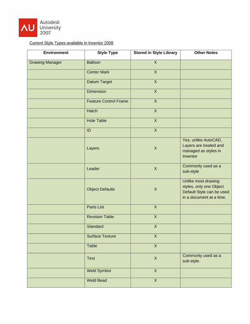
Current Style Types available in Inventor 2008
Environment Style Type Stored in Style Library Other Notes
Drawing Manager Balloon X
Center Mark X
Datum Target X
Dimension X
Feature Control Frame X
Hatch X
Hole Table X
ID X
Layers X
Yes, unlike AutoCAD, Layers are treated and managed as styles in Inventor
Leader X Commonly used as a sub-style
Object Defaults X
Unlike most drawing styles, only one Object Default Style can be used in a document at a time.
Parts List X
Revision Table X
Standard X
Surface Texture X
Table X
Text X Commonly used as a sub-style.
Weld Symbol X
Weld Bead X
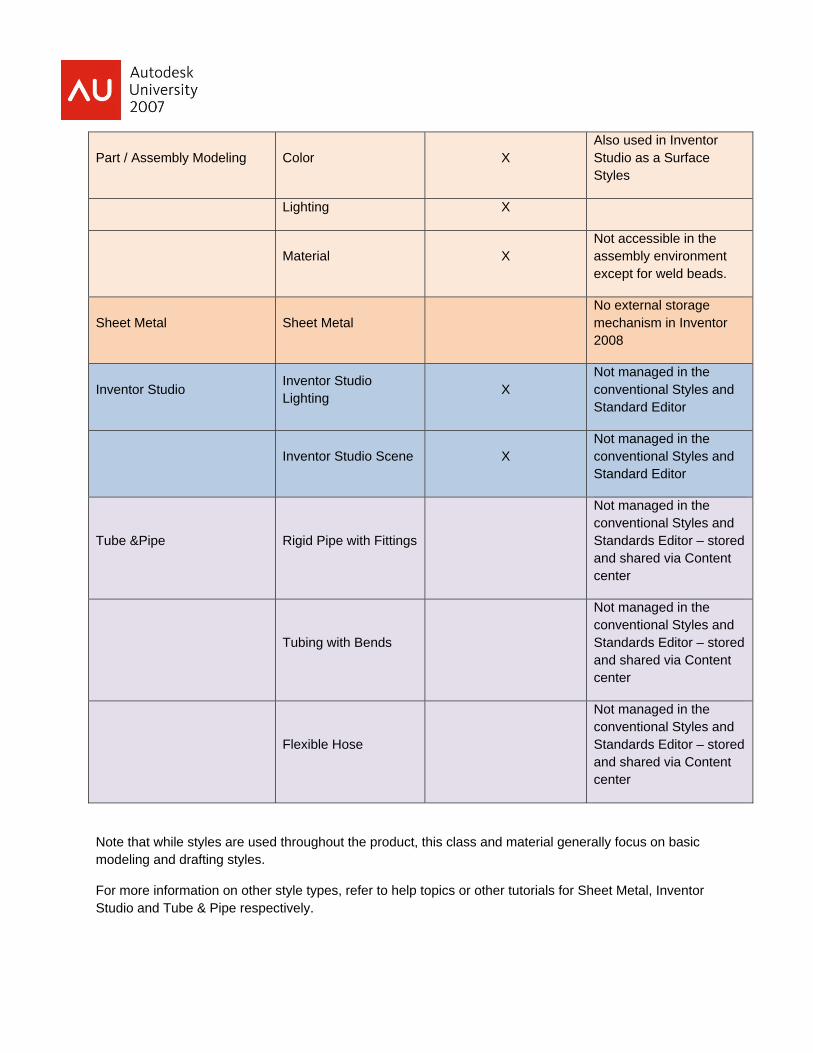
Part / Assembly Modeling Color X Also used in Inventor Studio as a Surface Styles
Lighting X
Material X Not accessible in the assembly environment except for weld beads.
Sheet Metal Sheet Metal No external storage mechanism in Inventor 2008
Inventor Studio Inventor Studio Lighting X
Not managed in the conventional Styles and Standard Editor
Inventor Studio Scene X Not managed in the conventional Styles and Standard Editor
Tube &Pipe Rigid Pipe with Fittings
Not managed in the conventional Styles and Standards Editor – stored and shared via Content center
Tubing with Bends
Not managed in the conventional Styles and Standards Editor – stored and shared via Content center
Flexible Hose
Not managed in the conventional Styles and Standards Editor – stored and shared via Content center
Note that while styles are used throughout the product, this class and material generally focus on basic modeling and drafting styles.
For more information on other style types, refer to help topics or other tutorials for Sheet Metal, Inventor Studio and Tube & Pipe respectively.

A Brief History of Inventor Styles
Styles have been part of Inventor since its inception and first release back in 2000. At that time, styles were mainly employed on the modeling side with Material, Color and Lighting Styles. These styles were stored in the modeling documents (.iam and .ipt files) and could be shared between documents using a utility called the Style Organizer.
Not until Inventor R4 did Drawing Manager first start using styles; starting only with text and dimension styles. Formatting for all other kinds of drawing annotation and geometry were configured in a Standards dialog and stored with the document. These settings could not easily be shared between files or users.
Inventor R9 (released in 2004) saw an extensive overhaul to the styles framework. Many new Drawing Manager Styles were added to the styles framework (generally speaking, one object style per type of annotation) and an external, XML-based storage mechanism was provided for all Inventor styles (except sheet metal).
The R9 styles project (internally called “the SSL project” – Styles, Standards and Layers) provided the following user-benefits:
• External style library provided increased capacity in the modeling environment. Prior to R9, every color, lighting and material style definition was stored with each part file. Each part file generally stored 30-40 of these styles by default (unless a user thought to purge out unused styles). This means that each bolt was storing color definitions for green, blue, glass and purple, even though grey was the active color. Instance this bolt 300 times in an assembly document, 300 instances of all of the unused style definitions are loaded with the assembly. Using the style library, only the active color, material and lighting styles are cached (loaded) in the component files while all other style definitions are stored externally in an XML-based style library.
• A consistent and convenient means to share styles between files and users. This ability was best realized in drawing manager where there previously was no means to share formatting settings other than text and dimension styles. The external style library as well as the style import / export commands provided an easy mechanism for work groups to share and utilize styles resulting in consistently-formatted drawings, and allowed customers and vendors to share styles to ensure proper drafting practices were being followed.
• Reduced (not eliminated) reliance on how Inventor interpreted drafting standards. Prior to the SSL project, much of the formatting for certain annotation objects was hard-coded based on whatever drafting standard (ANSI, ISO, DIN) was set to active on object creation (weld symbols, feature-control-frames).
• Introduced Layers to Inventor drawings. Layers provide users with very extensive formatting and object visibility tools. Layers also are a common AutoCAD formatting device, so enabling them in Inventor provided a familiar formatting option to new users coming from AutoCAD-based products as well as providing better idw-to-dwg translation options.
Styles in Inventor – the where and the how
There are several areas in the Inventor user-interface that use or reference styles:
• Styles commands in the Format drop-down menu • Styles and Standards Editor
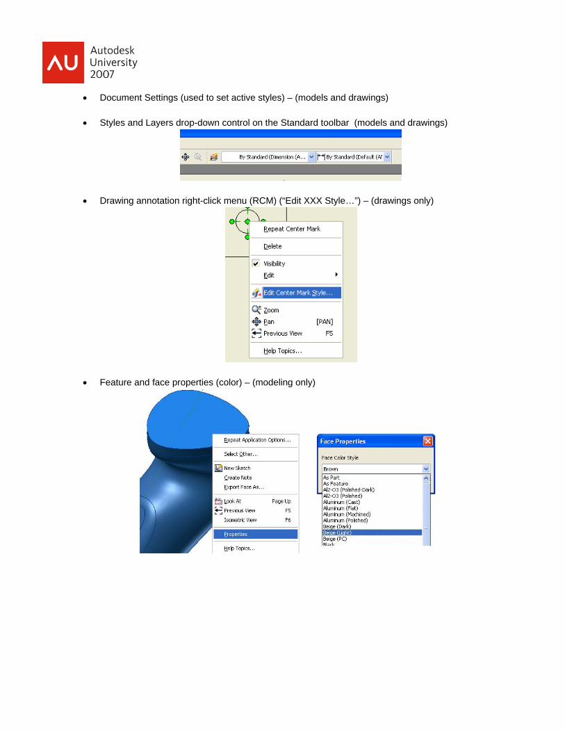
• Document Settings (used to set active styles) – (models and drawings) • Styles and Layers drop-down control on the Standard toolbar (models and drawings)
• Drawing annotation right-click menu (RCM) (“Edit XXX Style…”) – (drawings only)
• Feature and face properties (color) – (modeling only)
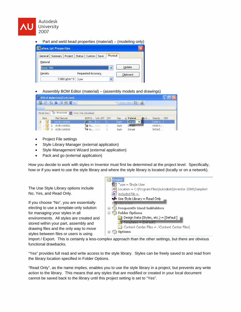
• Part and weld bead properties (material) – (modeling only)
• Assembly BOM Editor (material) – (assembly models and drawings)
• Project File settings • Style Library Manager (external application) • Style Management Wizard (external application) • Pack and go (external application)
How you decide to work with styles in Inventor must first be determined at the project level. Specifically, how or if you want to use the style library and where the style library is located (locally or on a network).
The Use Style Library options include No, Yes, and Read Only.
If you choose “No”, you are essentially electing to use a template-only solution for managing your styles in all environments. All styles are created and stored within your part, assembly and drawing files and the only way to move styles between files or users is using Import / Export. This is certainly a less-complex approach than the other settings, but there are obvious functional drawbacks.
“Yes” provides full read and write access to the style library. Styles can be freely saved to and read from the library location specified in Folder Options.
“Read Only”, as the name implies, enables you to use the style library in a project, but prevents any write action to the library. This means that any styles that are modified or created in your local document cannot be saved back to the library until this project setting is set to “Yes”.
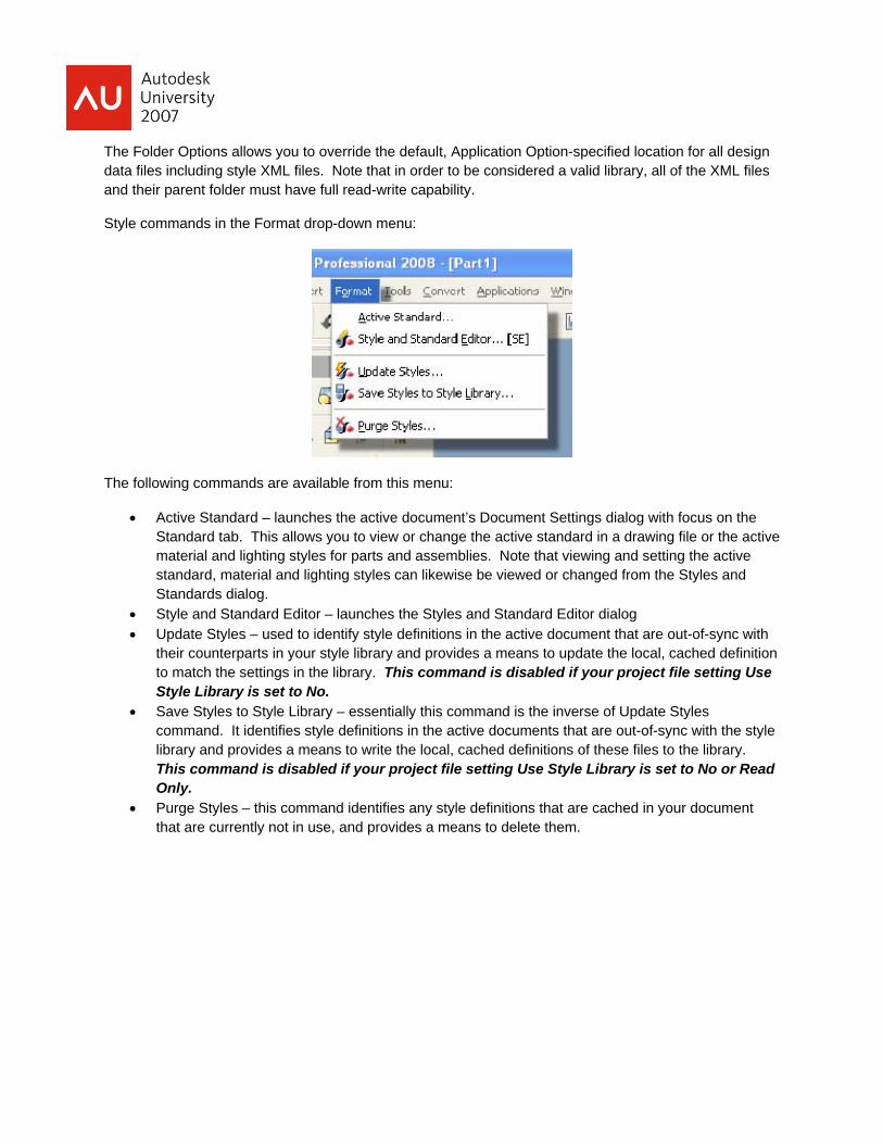
The Folder Options allows you to override the default, Application Option-specified location for all design data files including style XML files. Note that in order to be considered a valid library, all of the XML files and their parent folder must have full read-write capability.
Style commands in the Format drop-down menu:
The following commands are available from this menu:
• Active Standard – launches the active document’s Document Settings dialog with focus on the Standard tab. This allows you to view or change the active standard in a drawing file or the active material and lighting styles for parts and assemblies. Note that viewing and setting the active standard, material and lighting styles can likewise be viewed or changed from the Styles and Standards dialog.
• Style and Standard Editor – launches the Styles and Standard Editor dialog • Update Styles – used to identify style definitions in the active document that are out-of-sync with
their counterparts in your style library and provides a means to update the local, cached definition to match the settings in the library. This command is disabled if your project file setting Use Style Library is set to No.
• Save Styles to Style Library – essentially this command is the inverse of Update Styles command. It identifies style definitions in the active documents that are out-of-sync with the style library and provides a means to write the local, cached definitions of these files to the library. This command is disabled if your project file setting Use Style Library is set to No or Read Only.
• Purge Styles – this command identifies any style definitions that are cached in your document that are currently not in use, and provides a means to delete them.
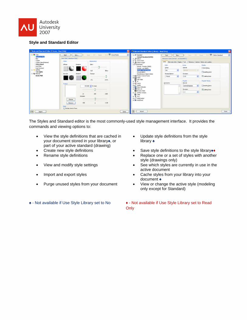
Style and Standard Editor
The Styles and Standard editor is the most commonly-used style management interface. It provides the commands and viewing options to:
• View the style definitions that are cached in your document stored in your library♠, or part of your active standard (drawing)
• Update style definitions from the style library ♠
• Create new style definitions • Save style definitions to the style library♠♦ • Rename style definitions • Replace one or a set of styles with another
style (drawings only) • View and modify style settings • See which styles are currently in use in the
active document • Import and export styles • Cache styles from your library into your
document ♠ • Purge unused styles from your document • View or change the active style (modeling
only except for Standard)
♠ - Not available if Use Style Library set to No ♦ - Not available if Use Style Library set to Read Only
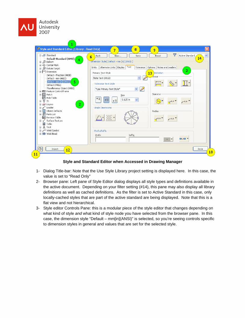
Style and Standard Editor when Accessed in Drawing Manager
1- Dialog Title-bar: Note that the Use Style Library project setting is displayed here. In this case, the value is set to “Read Only”
2- Browser pane: Left pane of Style Editor dialog displays all style types and definitions available in the active document. Depending on your filter setting (#14), this pane may also display all library definitions as well as cached definitions. As the filter is set to Active Standard in this case, only locally-cached styles that are part of the active standard are being displayed. Note that this is a flat view and not hierarchical.
3- Style editor Controls Pane: this is a modular piece of the style editor that changes depending on what kind of style and what kind of style node you have selected from the browser pane. In this case, the dimension style “Default – mm[in](ANSI)” is selected, so you’re seeing controls specific to dimension styles in general and values that are set for the selected style.
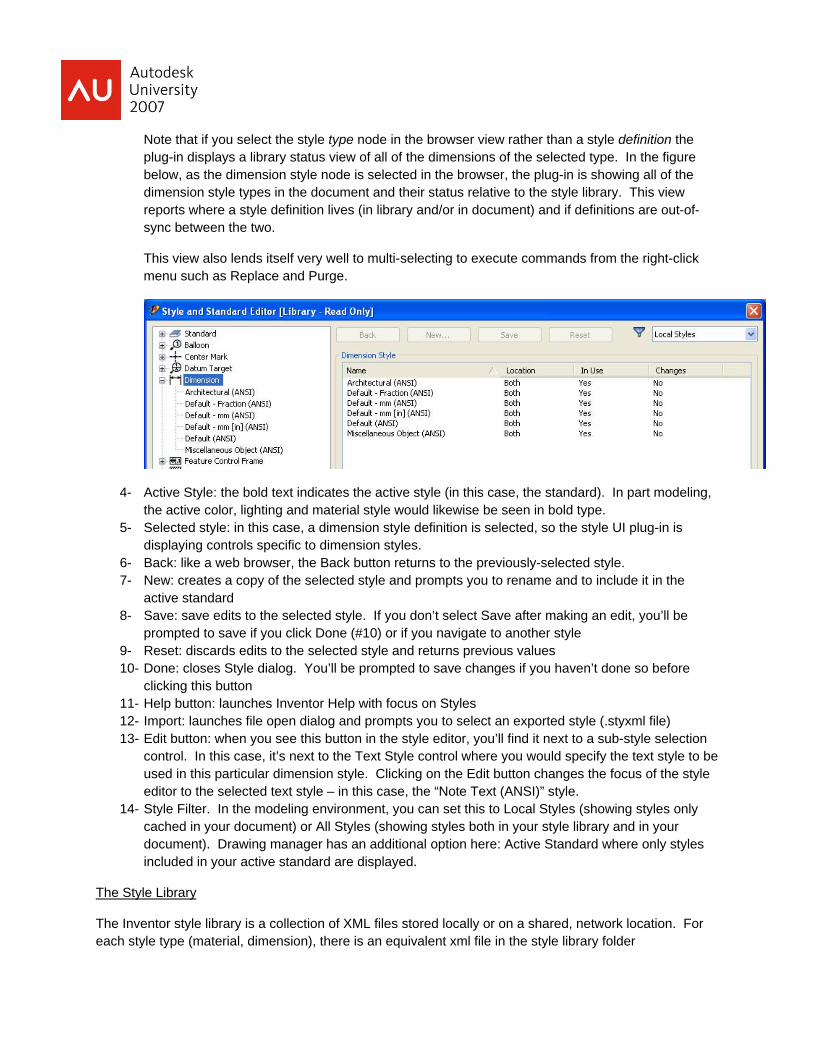
Note that if you select the style type node in the browser view rather than a style definition the plug-in displays a library status view of all of the dimensions of the selected type. In the figure below, as the dimension style node is selected in the browser, the plug-in is showing all of the dimension style types in the document and their status relative to the style library. This view reports where a style definition lives (in library and/or in document) and if definitions are out-of-sync between the two.
This view also lends itself very well to multi-selecting to execute commands from the right-click menu such as Replace and Purge.
4- Active Style: the bold text indicates the active style (in this case, the standard). In part modeling, the active color, lighting and material style would likewise be seen in bold type.
5- Selected style: in this case, a dimension style definition is selected, so the style UI plug-in is displaying controls specific to dimension styles.
6- Back: like a web browser, the Back button returns to the previously-selected style. 7- New: creates a copy of the selected style and prompts you to rename and to include it in the
active standard 8- Save: save edits to the selected style. If you don’t select Save after making an edit, you’ll be
prompted to save if you click Done (#10) or if you navigate to another style 9- Reset: discards edits to the selected style and returns previous values 10- Done: closes Style dialog. You’ll be prompted to save changes if you haven’t done so before
clicking this button 11- Help button: launches Inventor Help with focus on Styles 12- Import: launches file open dialog and prompts you to select an exported style (.styxml file) 13- Edit button: when you see this button in the style editor, you’ll find it next to a sub-style selection
control. In this case, it’s next to the Text Style control where you would specify the text style to be used in this particular dimension style. Clicking on the Edit button changes the focus of the style editor to the selected text style – in this case, the “Note Text (ANSI)” style.
14- Style Filter. In the modeling environment, you can set this to Local Styles (showing styles only cached in your document) or All Styles (showing styles both in your style library and in your document). Drawing manager has an additional option here: Active Standard where only styles included in your active standard are displayed.
The Style Library
The Inventor style library is a collection of XML files stored locally or on a shared, network location. For each style type (material, dimension), there is an equivalent xml file in the style library folder
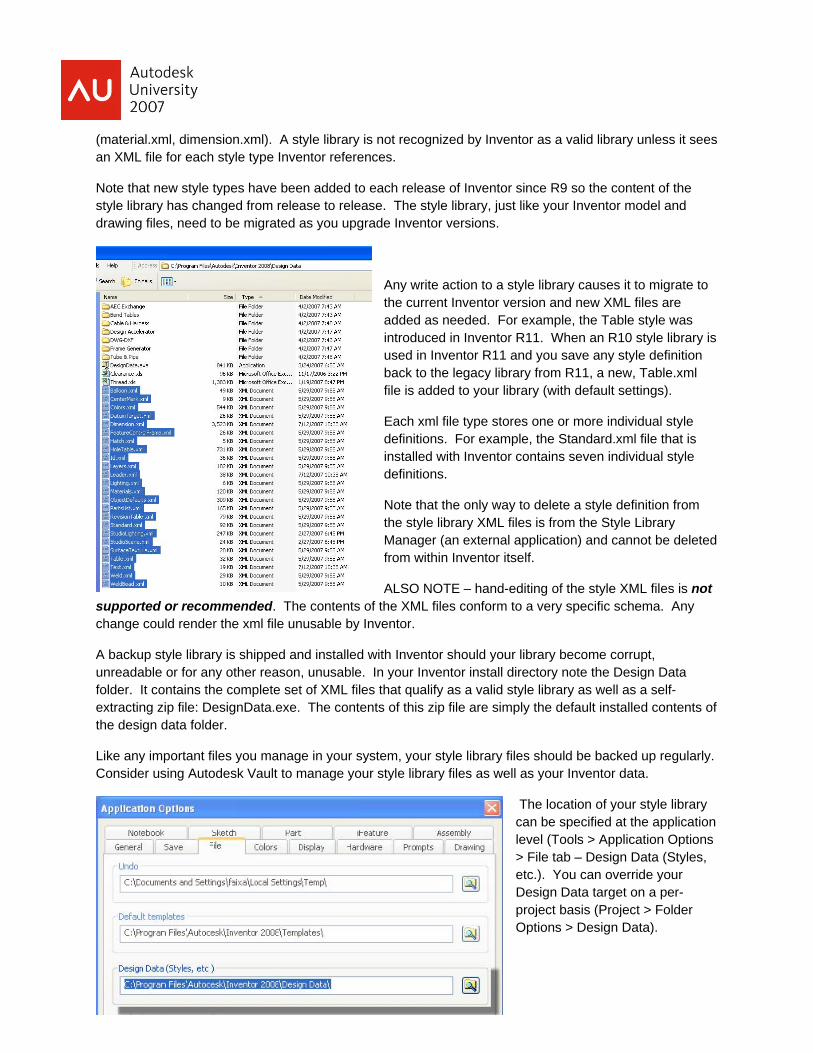
(material.xml, dimension.xml). A style library is not recognized by Inventor as a valid library unless it sees an XML file for each style type Inventor references.
Note that new style types have been added to each release of Inventor since R9 so the content of the style library has changed from release to release. The style library, just like your Inventor model and drawing files, need to be migrated as you upgrade Inventor versions.
Any write action to a style library causes it to migrate to the current Inventor version and new XML files are added as needed. For example, the Table style was introduced in Inventor R11. When an R10 style library is used in Inventor R11 and you save any style definition back to the legacy library from R11, a new, Table.xml file is added to your library (with default settings).
Each xml file type stores one or more individual style definitions. For example, the Standard.xml file that is installed with Inventor contains seven individual style definitions.
Note that the only way to delete a style definition from the style library XML files is from the Style Library Manager (an external application) and cannot be deleted from within Inventor itself.
ALSO NOTE – hand-editing of the style XML files is not supported or recommended. The contents of the XML files conform to a very specific schema. Any change could render the xml file unusable by Inventor.
A backup style library is shipped and installed with Inventor should your library become corrupt, unreadable or for any other reason, unusable. In your Inventor install directory note the Design Data folder. It contains the complete set of XML files that qualify as a valid style library as well as a self-extracting zip file: DesignData.exe. The contents of this zip file are simply the default installed contents of the design data folder.
Like any important files you manage in your system, your style library files should be backed up regularly. Consider using Autodesk Vault to manage your style library files as well as your Inventor data.
The location of your style library can be specified at the application level (Tools > Application Options > File tab – Design Data (Styles, etc.). You can override your Design Data target on a per-project basis (Project > Folder Options > Design Data).
It may be advantageous, depending on the kind of work that you do, to maintain two or more style libraries. This would be especially true for contract design companies that cater to many different customers each with their own formatting and drafting rules. Generally speaking, you’d also likely maintain concurrent, specialized Inventor file templates for each style library.
Modeling versus Drawing Styles
The behavior and workflows of styles in both the modeling and drawing environments are generally similar but have several key, notable differences.
For example, a part file can only have one material, one color and one lighting style applied at any time (although features and faces can have color overrides). Generally speaking, only one modeling style is active at a time and when using the style library, only one of each style needs to be cached in the document. All other styles are stored in and accessed from the project’s style library.
Drawing styles behave more like a set of drafting rules rather than simple formatting options. Drawing styles are managed as a complete Standard. A Standard is a high-level style that “owns” other drawing sub-styles like parts list and dimension styles.
Styles, sub-styles and overrides
Many style types are managed as sub-styles or child styles of a higher-level style. For example: a color style is stored as a sub-style of the material style, all drawing manager styles are managed as sub-styles of the standard style and the dimension styles use both leader and text sub-styles.
Use of sub-styles introduces parent-child associative relationships. The child or sub-style cannot be purged if the parent style is in use. If the parent style is exported, the child styles are written out (and read in) as part of the XML style definition. If a parent style is cached into a document from the library, its sub-styles are likewise cached into the document.
Working with Modeling Styles – Workflow Examples
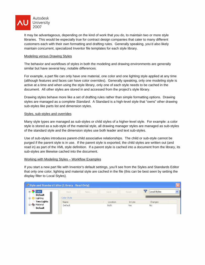
If you start a new part file with Inventor’s default settings, you’ll see from the Styles and Standards Editor that only one color, lighting and material style are cached in the file (this can be best seen by setting the display filter to Local Styles).
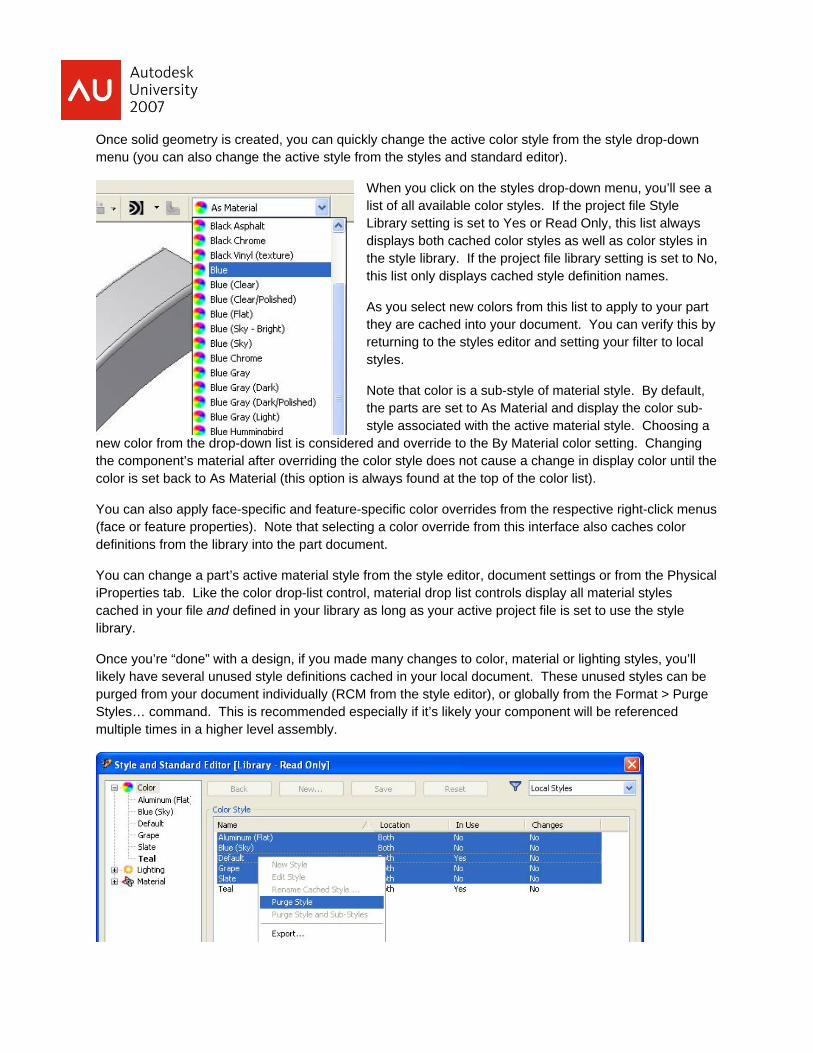
Once solid geometry is created, you can quickly change the active color style from the style drop-down menu (you can also change the active style from the styles and standard editor).
When you click on the styles drop-down menu, you’ll see a list of all available color styles. If the project file Style Library setting is set to Yes or Read Only, this list always displays both cached color styles as well as color styles in the style library. If the project file library setting is set to No, this list only displays cached style definition names.
As you select new colors from this list to apply to your part they are cached into your document. You can verify this by returning to the styles editor and setting your filter to local styles.
Note that color is a sub-style of material style. By default, the parts are set to As Material and display the color sub-style associated with the active material style. Choosing a
new color from the drop-down list is considered and override to the By Material color setting. Changing the component’s material after overriding the color style does not cause a change in display color until the color is set back to As Material (this option is always found at the top of the color list).
You can also apply face-specific and feature-specific color overrides from the respective right-click menus (face or feature properties). Note that selecting a color override from this interface also caches color definitions from the library into the part document.
You can change a part’s active material style from the style editor, document settings or from the Physical iProperties tab. Like the color drop-list control, material drop list controls display all material styles cached in your file and defined in your library as long as your active project file is set to use the style library.
Once you’re “done” with a design, if you made many changes to color, material or lighting styles, you’ll likely have several unused style definitions cached in your local document. These unused styles can be purged from your document individually (RCM from the style editor), or globally from the Format > Purge Styles… command. This is recommended especially if it’s likely your component will be referenced multiple times in a higher level assembly.
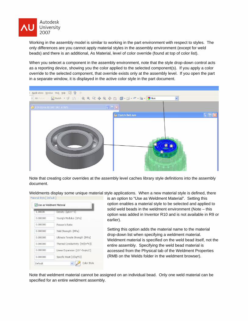
Working in the assembly model is similar to working in the part environment with respect to styles. The only differences are you cannot apply material styles in the assembly environment (except for weld beads) and there is an additional, As Material, level of color override (found at top of color list).
When you selecet a component in the assembly environment, note that the style drop-down control acts as a reporting device, showing you the color applied to the selected component(s). If you apply a color override to the selected component, that override exists only at the assembly level. If you open the part in a separate window, it is displayed in the active color style in the part document.
Note that creating color overrides at the assembly level caches library style definitions into the assembly document.
Weldments display some unique material style applications. When a new material style is defined, there is an option to “Use as Weldment Material”. Setting this option enables a material style to be selected and applied to solid weld beads in the weldment environment (Note – this option was added in Inventor R10 and is not available in R9 or earlier).
Setting this option adds the material name to the material drop-down list when specifying a weldment material. Weldment material is specified on the weld bead itself, not the entire assembly. Specifying the weld bead material is accessed from the Physical tab of the Weldment Properties (RMB on the Welds folder in the weldment browser).
Note that weldment material cannot be assigned on an individual bead. Only one weld material can be specified for an entire weldment assembly.
Defining a modeling Style
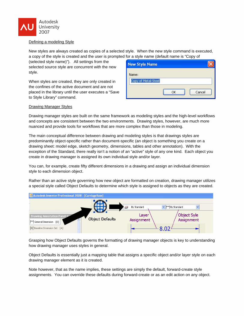
New styles are always created as copies of a selected style. When the new style command is executed, a copy of the style is created and the user is prompted for a style name (default name is “Copy of (selected style name)”). All settings from the selected source style are concurrent with the new style.
When styles are created, they are only created in the confines of the active document and are not placed in the library until the user executes a “Save to Style Library” command.
Drawing Manager Styles
Drawing manager styles are built on the same framework as modeling styles and the high-level workflows and concepts are consistent between the two environments. Drawing styles, however, are much more nuanced and provide tools for workflows that are more complex than those in modeling.
The main conceptual difference between drawing and modeling styles is that drawings styles are predominantly object-specific rather than document-specific (an object is something you create on a drawing sheet: model edge, sketch geometry, dimensions, tables and other annotation). With the exception of the Standard, there really isn’t a notion of an “active” style of any one kind. Each object you create in drawing manager is assigned its own individual style and/or layer.
You can, for example, create fifty different dimensions in a drawing and assign an individual dimension style to each dimension object.
Rather than an active style governing how new object are formatted on creation, drawing manager utilizes a special style called Object Defaults to determine which style is assigned to objects as they are created.
Grasping how Object Defaults governs the formatting of drawing manager objects is key to understanding how drawing manager uses styles in general.
Object Defaults is essentially just a mapping table that assigns a specific object and/or layer style on each drawing manager element as it is created.
Note however, that as the name implies, these settings are simply the default, forward-create style assignments. You can override these defaults during forward-create or as an edit action on any object.
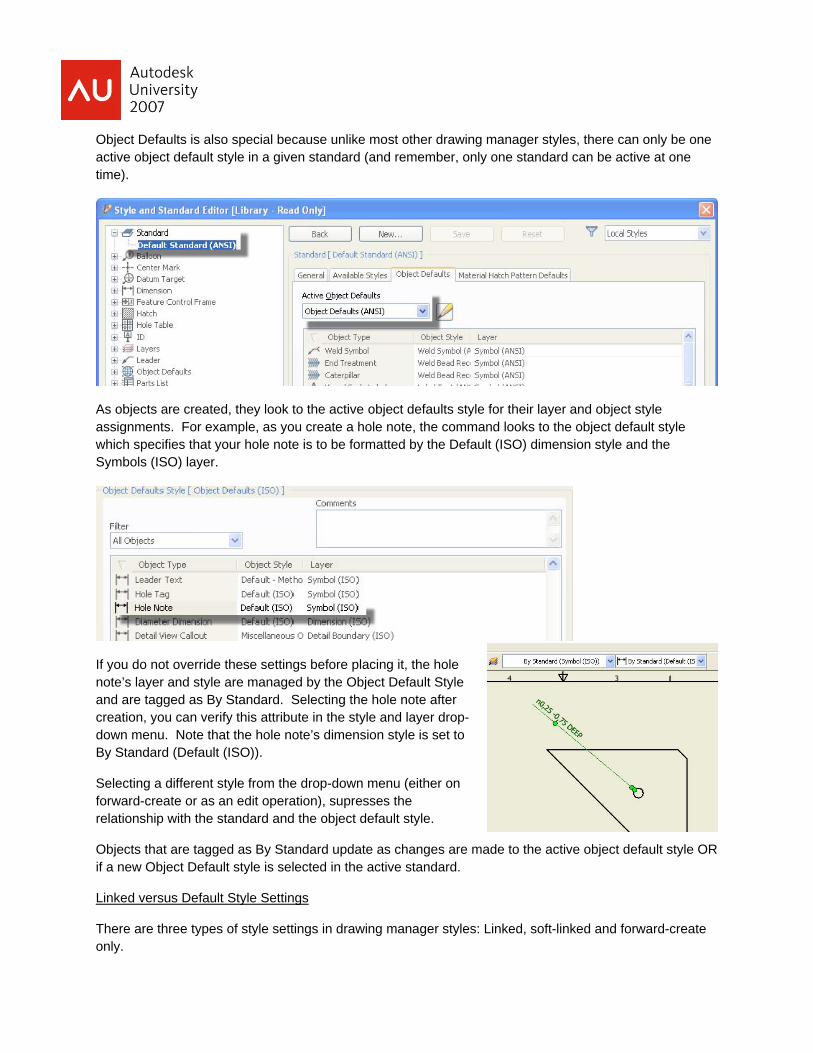
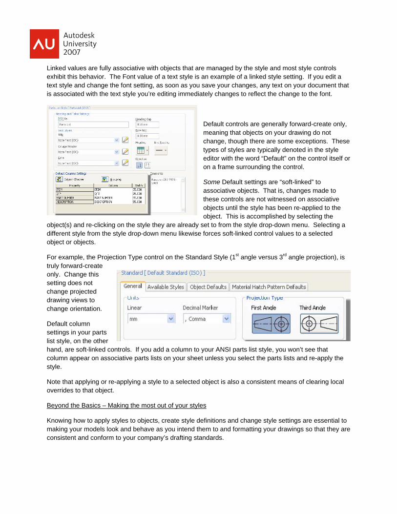
Object Defaults is also special because unlike most other drawing manager styles, there can only be one active object default style in a given standard (and remember, only one standard can be active at one time).
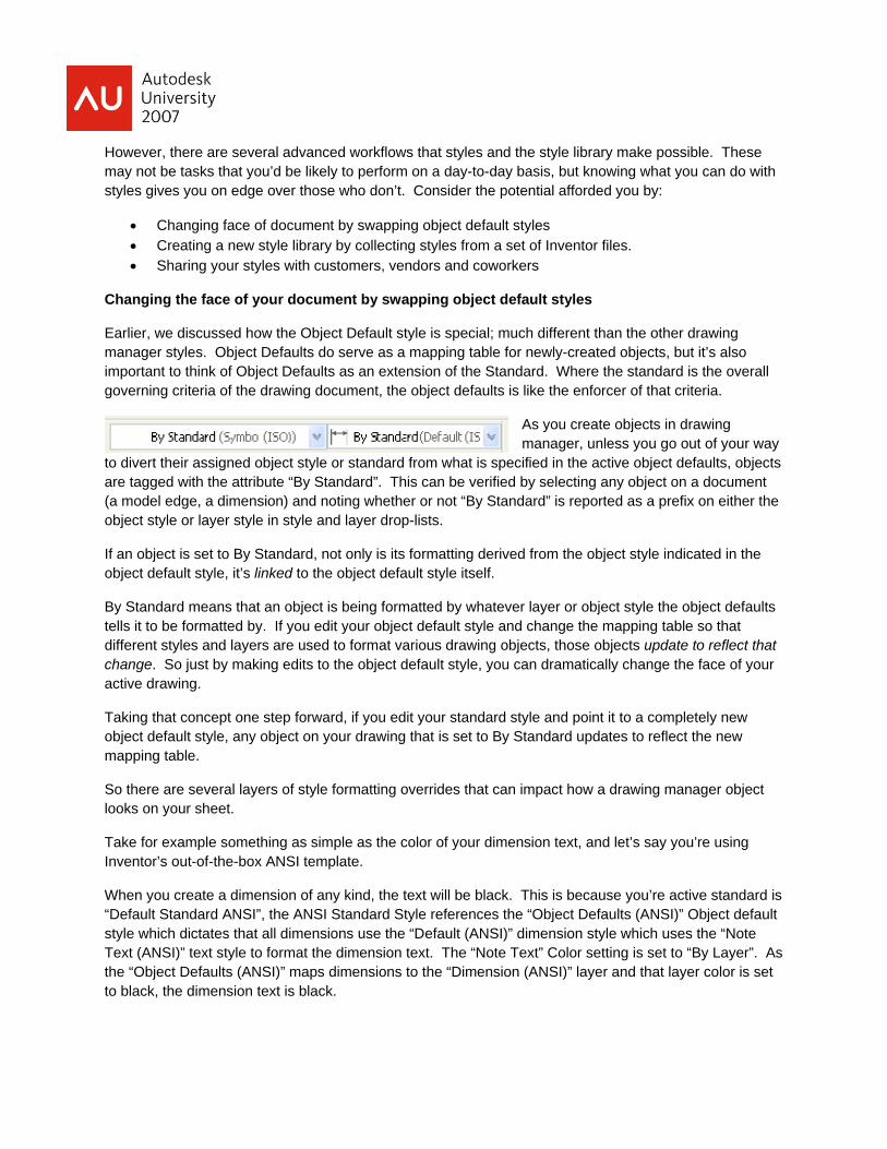
As objects are created, they look to the active object defaults style for their layer and object style assignments. For example, as you create a hole note, the command looks to the object default style which specifies that your hole note is to be formatted by the Default (ISO) dimension style and the Symbols (ISO) layer.
If you do not override these settings before placing it, the hole note’s layer and style are managed by the Object Default Style and are tagged as By Standard. Selecting the hole note after creation, you can verify this attribute in the style and layer drop-down menu. Note that the hole note’s dimension style is set to By Standard (Default (ISO)).
Selecting a different style from the drop-down menu (either on forward-create or as an edit operation), supresses the relationship with the standard and the object default style.
Objects that are tagged as By Standard update as changes are made to the active object default style OR if a new Object Default style is selected in the active standard.
Linked versus Default Style Settings
There are three types of style settings in drawing manager styles: Linked, soft-linked and forward-create only.
Linked values are fully associative with objects that are managed by the style and most style controls exhibit this behavior. The Font value of a text style is an example of a linked style setting. If you edit a text style and change the font setting, as soon as you save your changes, any text on your document that is associated with the text style you’re editing immediately changes to reflect the change to the font.
Default controls are generally forward-create only, meaning that objects on your drawing do not change, though there are some exceptions. These types of styles are typically denoted in the style editor with the word “Default” on the control itself or on a frame surrounding the control.
Some Default settings are “soft-linked” to associative objects. That is, changes made to these controls are not witnessed on associative objects until the style has been re-applied to the object. This is accomplished by selecting the
object(s) and re-clicking on the style they are already set to from the style drop-down menu. Selecting a different style from the style drop-down menu likewise forces soft-linked control values to a selected object or objects.
For example, the Projection Type control on the Standard Style (1st angle versus 3rd angle projection), is truly forward-create only. Change this setting does not change projected drawing views to change orientation.
Default column settings in your parts list style, on the other hand, are soft-linked controls. If you add a column to your ANSI parts list style, you won’t see that column appear on associative parts lists on your sheet unless you select the parts lists and re-apply the style.
Note that applying or re-applying a style to a selected object is also a consistent means of clearing local overrides to that object.
Beyond the Basics – Making the most out of your styles
Knowing how to apply styles to objects, create style definitions and change style settings are essential to making your models look and behave as you intend them to and formatting your drawings so that they are consistent and conform to your company’s drafting standards.
However, there are several advanced workflows that styles and the style library make possible. These may not be tasks that you’d be likely to perform on a day-to-day basis, but knowing what you can do with styles gives you on edge over those who don’t. Consider the potential afforded you by:
• Changing face of document by swapping object default styles • Creating a new style library by collecting styles from a set of Inventor files. • Sharing your styles with customers, vendors and coworkers
Changing the face of your document by swapping object default styles
Earlier, we discussed how the Object Default style is special; much different than the other drawing manager styles. Object Defaults do serve as a mapping table for newly-created objects, but it’s also important to think of Object Defaults as an extension of the Standard. Where the standard is the overall governing criteria of the drawing document, the object defaults is like the enforcer of that criteria.
As you create objects in drawing manager, unless you go out of your way
to divert their assigned object style or standard from what is specified in the active object defaults, objects are tagged with the attribute “By Standard”. This can be verified by selecting any object on a document (a model edge, a dimension) and noting whether or not “By Standard” is reported as a prefix on either the object style or layer style in style and layer drop-lists.
If an object is set to By Standard, not only is its formatting derived from the object style indicated in the object default style, it’s linked to the object default style itself.
By Standard means that an object is being formatted by whatever layer or object style the object defaults tells it to be formatted by. If you edit your object default style and change the mapping table so that different styles and layers are used to format various drawing objects, those objects update to reflect that change. So just by making edits to the object default style, you can dramatically change the face of your active drawing.
Taking that concept one step forward, if you edit your standard style and point it to a completely new object default style, any object on your drawing that is set to By Standard updates to reflect the new mapping table.
So there are several layers of style formatting overrides that can impact how a drawing manager object looks on your sheet.
Take for example something as simple as the color of your dimension text, and let’s say you’re using Inventor’s out-of-the-box ANSI template.
When you create a dimension of any kind, the text will be black. This is because you’re active standard is “Default Standard ANSI”, the ANSI Standard Style references the “Object Defaults (ANSI)” Object default style which dictates that all dimensions use the “Default (ANSI)” dimension style which uses the “Note Text (ANSI)” text style to format the dimension text. The “Note Text” Color setting is set to “By Layer”. As the “Object Defaults (ANSI)” maps dimensions to the “Dimension (ANSI)” layer and that layer color is set to black, the dimension text is black.
Standard references Object Default Style Object Default Style references Dimension Style
Dimension Style references Text Style • Text Style color set to By Layer
Object Default Style references Layer
Layer color is black, therefore dimension color is black
That means that you can change the text color of your dimensions (intentionally or not) by changing any one of five style settings, or by selecting the dimension and putting it on a different layer.
The right way to change the dimension’s text color is dependent on whether you want that change to affect all of your dimensions, all of your linear dimensions or only a selected dimension.
With multiple levels of control, you have ultimate flexibility over how your documents are formatted.
Consider a company that is required to create both ANSI-inch-based documents and ISO-mm-based documents when they document their models.
With styles, this is pretty easy. You could:
• add all of your views, notes, dimensions, and other annotation,
• then save it,
• then cache in the ISO standard into your document,
• then apply the ISO-flavored style to each object and selecting a new style from the style drop-down menu
(we’ll call this scenario A).
A an easier way to achieve the same end result is by caching in the ISO standard, then editing the ANSI object default style and replacing each ANSI-based style with it’s ISO equivalent for each object row. Any and all objects in your document that are set to “By Standard” update to become ISO (scenario B).
EVEN EASIER: cache in the ISO standard, edit your ANSI standard and set it to use the ISO Object Default style…Done! (scenario C).
Scenario A is what you would have to do in AutoCAD or in Inventor previous to R9. Scenario A is also your only option if you don’t appreciate how Object Defaults manages your documents style settings.
If you had to change 400 annotation objects on your document (not at all out-of-the question), scenario C could easily save you several hours of work over scenario A.
Another very important reason why scenario C is better than scenario A is that any local overrides you had on your objects are cleared if you apply a new style to that object (something as simple as appending text or changing the precision of a dimension).
Scenario C (swapping object default styles) preserves all local object overrides while still changing the underlying, styles-based formatting.
Create a new style library by collecting styles from a set of Inventor files
The Style Management Wizard is purpose built to combing through a specified set of Inventor files, collecting all of the local style definitions within those files and writing them all out as a complete (or appending to an already existing) style library.
This tool was especially important when the new styles environment was first introduced in R9. Prior to that time, all styles were stored in local documents. Some documents may have had four dimension styles that you needed, but on one project, you had to create a few special dimension styles to get the job done.
The Style Management Wizard allowed you to collect all of those scattered styles into one central repository (of course this worked with modeling styles as well).
Today, this tool is very useful for new Inventor customers coming over from AutoCAD and for users who are transitioning into working with a style library altogether.
Remember, you don’t have to use the style library. If you’re Use Style Library project setting is set to No, that’s it. You’re working in your local documents only, and you may have good reasons to do that. When or if you’re ready to move from that kind of style management paradigm into using the library, the Style Management Wizard is there to build a library from your Inventor file templates and other Inventor documents.
Note that your Inventor files need to be migrated to the current release to run this tool.
Note for AutoCAD users coming over into Inventor: with the DWG True Connect technology introduced in Inventor 2008, the Style Management Wizard enables you to harvest dimension and text style directly from your AutoCAD dwg files. This should make setting up your Inventor templates and your default style library to behave similarly to your AutoCAD templates much easier (note that for the Harvester to recognize dimension and text styles in a dwg file, it first needs to be opened and saved as an Inventor dwg file).
Also note that the Style Management Wizard also provides an automation tool for auditing a large selection of files and purging out all unreferenced styles.
Sharing your styles with customers, vendors and coworkers
If you take the time to build a robust and complete set of styles, you’ll likely need an efficient means to share those styles with peers, other internal design groups or even external parties such as customers or vendors.
There are three methods you can employ to share styles among Inventor users.
1 – Provide access to your Inventor templates. This is a completely non-XML-based solution. It would require that any and all styles that your recipients may need be defined and cached in your documents. This is essentially the way styles have always been shared and this technique is certainly not exclusive to Inventor.

One important caveat to this method is that your recipients are going to get a lot more than just styles. They’ll get file properties, title-blocks, sketch symbols, and anything else you have stored in your template files. While many times, sharing all of this data is important, there are plenty of examples where you might not want to provide all of this extra data.
2 – Provide a full style library. One way to accomplish this is by using Windows Explorer to navigate out to the folder containing your library, selecting all of the valid XML files that comprise a valid style library, adding them to a .zip file and sending the ZIP file out as needed.
3 – Export your styles as a .styxml file. This is probably the simplest and most efficient way to share styles. Simply RMB on one or more styles from your Styles and Standards Editor (you can multi-select when you selection in the browser pane is on the style type collector) and choose “Export…” from the right-click menu.
Remember, the export command gathers up all substyles from a selected style. This means that in the drawing environment, as long as you have all of your styles added to your standard (you can verify this by editing your standard and looking at the Available Styles tab), you can gather up all of your drawing manager styles in one .styxml file.
Once that file is made available, all a user needs to do is start the Styles and Standard Editor, select the Import button and pull in your exported standard. This command overwrites any local settings should a name collision occur on style definitions.
Goodies and Idiosyncrasies
Replace Styles
Replace styles is a very powerful command that can quickly reduce the number of extraneous styles in your drawing files and enforce consistency across your drawing document.
Quite simply, it allows you to select multiple definitions of a particular style type, replace all of the definitions with a new definition and optionally purge out the replaced styles.
The command identifies and modifies all style references based on your selected styles including styles referenced by objects and referenced by other styles (this is especially significant with styles referenced in Object Defaults)
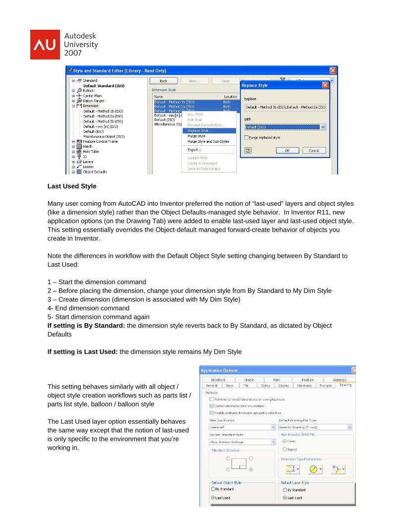
Last Used Style Many user coming from AutoCAD into Inventor preferred the notion of “last-used” layers and object styles (like a dimension style) rather than the Object Defaults-managed style behavior. In Inventor R11, new application options (on the Drawing Tab) were added to enable last-used layer and last-used object style. This setting essentially overrides the Object-default managed forward-create behavior of objects you create in Inventor. Note the differences in workflow with the Default Object Style setting changing between By Standard to Last Used: 1 – Start the dimension command 2 – Before placing the dimension, change your dimension style from By Standard to My Dim Style 3 – Create dimension (dimension is associated with My Dim Style) 4- End dimension command 5- Start dimension command again If setting is By Standard: the dimension style reverts back to By Standard, as dictated by Object Defaults If setting is Last Used: the dimension style remains My Dim Style This setting behaves similarly with all object / object style creation workflows such as parts list / parts list style, balloon / balloon style The Last Used layer option essentially behaves the same way except that the notion of last-used is only specific to the environment that you’re working in.
So if you create a new layer called GREEN, for example, then start the dimension command and change the active layer to GREEN, the next dimension you create will be on the GREEN layer. If you then create a center mark, it is likewise placed on the GREEN layer. However, if I switch environments in the drawing by creating a view sketch or editing a title-block, the layer is reset back to By Standard until I change it. Once I change the layer in the context of the sketch, the sketch itself remembers the Last Used layer, but again is resent when I exit out of the sketch. Leveraging Layers in Inventor The use of layers in Inventor Drawing Manager should be completely transparent. As you create views, sketches and annotation, these objects are placed on layers as dictated by Object Defaults, and few users even appreciate the level of formatting and visibility options afforded to them by layers. Consider a condition where you are documenting a part file that has numerous hole and other cut-outs. A side view with hidden lines displayed would be very cluttered as hidden lines would be displayed for each hole or cut. You can selectively pick the hidden lines you don’t want to see and turn off their visibility and this may be 90% of the hidden lines in a given view. Alternatively, you could create a new Hidden layer (call it My Hidden), select 10% of the hidden lines you want to keep, move them to your new layer, then turn off the main hidden line layer. In Inventor 2008 a new layer attribute was added, Plot. This option behaves the same as the layer Plot option in AutoCAD. Basically, any objects that are on a layer that is set not to plot are seen only when viewing the drawing file natively in Inventor or in Inventor View. Objects on layers that are set to not plot are not drawn on any publishing operation including Print and publishing DWF files. This means that you can add information to a drawing file that you might only want to see yourself or that you only want other Inventor users to see. Having layers in Inventor also lets you map Inventor layers to layers in AutoCAD and AutoCAD Mechanical as required by a down-stream consumer of your data. If you need a custom layer configuration for AutoCAD dwg export, simply create a new Object Default style with the proper object layer assignments and prior to saving out your drawing, edit your standard and change the active object default style to the one configured for your desired AutoCAD layer schema. Style conflict when creating a new drawing If your project Use Style Library project setting is set to Yes or Read only, you may see this error when you create a new drawing from your template.
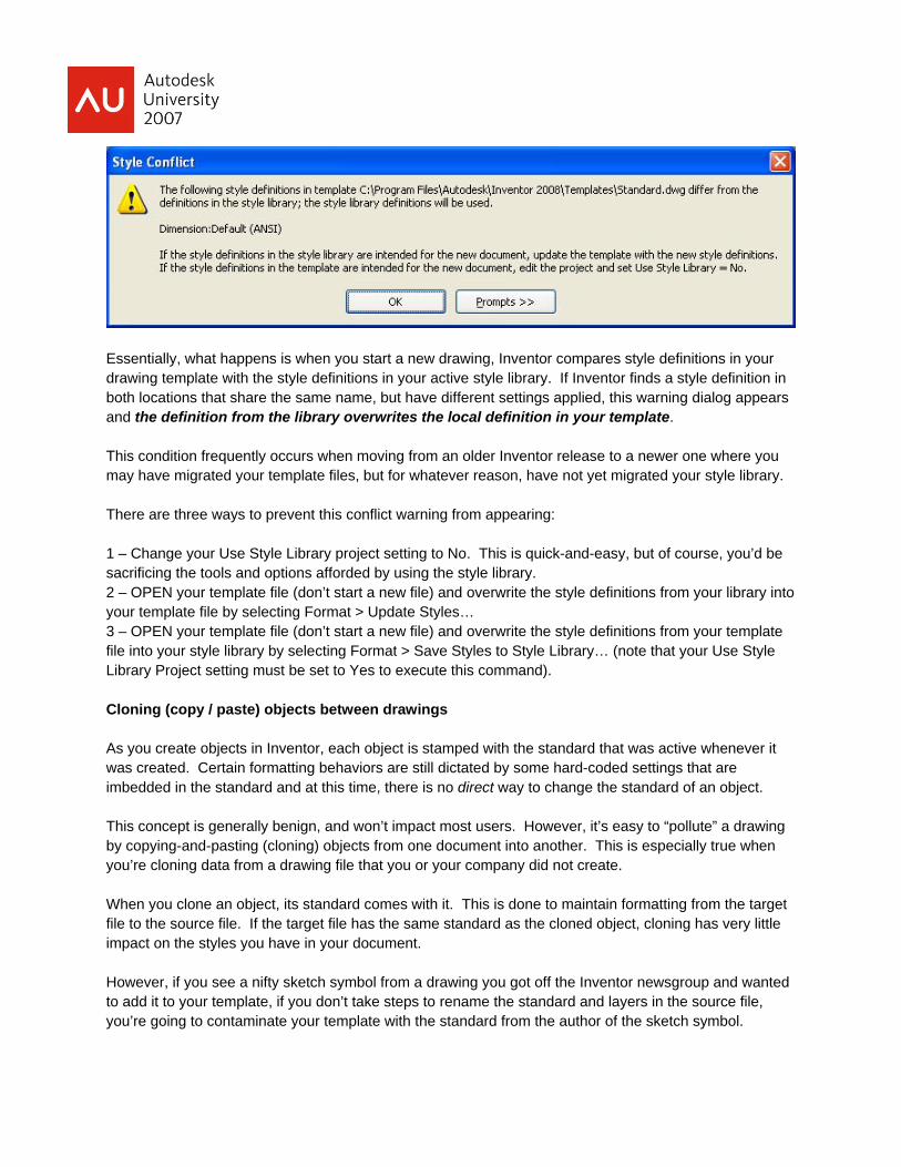
Essentially, what happens is when you start a new drawing, Inventor compares style definitions in your drawing template with the style definitions in your active style library. If Inventor finds a style definition in both locations that share the same name, but have different settings applied, this warning dialog appears and the definition from the library overwrites the local definition in your template. This condition frequently occurs when moving from an older Inventor release to a newer one where you may have migrated your template files, but for whatever reason, have not yet migrated your style library. There are three ways to prevent this conflict warning from appearing: 1 – Change your Use Style Library project setting to No. This is quick-and-easy, but of course, you’d be sacrificing the tools and options afforded by using the style library. 2 – OPEN your template file (don’t start a new file) and overwrite the style definitions from your library into your template file by selecting Format > Update Styles… 3 – OPEN your template file (don’t start a new file) and overwrite the style definitions from your template file into your style library by selecting Format > Save Styles to Style Library… (note that your Use Style Library Project setting must be set to Yes to execute this command). Cloning (copy / paste) objects between drawings As you create objects in Inventor, each object is stamped with the standard that was active whenever it was created. Certain formatting behaviors are still dictated by some hard-coded settings that are imbedded in the standard and at this time, there is no direct way to change the standard of an object. This concept is generally benign, and won’t impact most users. However, it’s easy to “pollute” a drawing by copying-and-pasting (cloning) objects from one document into another. This is especially true when you’re cloning data from a drawing file that you or your company did not create. When you clone an object, its standard comes with it. This is done to maintain formatting from the target file to the source file. If the target file has the same standard as the cloned object, cloning has very little impact on the styles you have in your document. However, if you see a nifty sketch symbol from a drawing you got off the Inventor newsgroup and wanted to add it to your template, if you don’t take steps to rename the standard and layers in the source file, you’re going to contaminate your template with the standard from the author of the sketch symbol.
Note that when a style name collision occurs on paste (i.e. – the name of the standard in your target file is identical to the name of the standard on the copied object), the target file’s style definition wins. This means that if my target and source file are both using a standard called My_ANSI but the target file’s object default style dictates that sketch data goes on the RED layer, a sketch symbol cloned from a document where sketch data is on the GREEN layer is going to be on the RED layer in the target document. Getting rid of unwanted standards in your document As mentioned in the previous section, without taking preventative steps to avoid it, you can very quickly and ignorantly add unwanted standard definitions into your drawing file. The best way to solve this problem is to never get into this situation to begin with. The two most common pitfalls that propagate this condition are cloning objects between files (mentioned in the previous section) and creating a new, custom standard in your template. If you plan on cloning objects (views, sketches, etc) from one drawing to another (especially if the source file wasn’t authored by you or someone in your company), verify that the source file has the same naming style convention as your target file (note that you don’t have to save these edits in the source file, you just need to make the change before you start a Copy command). Many users also frequently pollute their template files when they first edit it to create a custom standard (we’re under no illusions that our default standard settings meet everyone’s needs). Rather than renaming and modifying the default standard in the templates shipped with Inventor, many users create a copy of the standard and then modify it to their needs. This practice is absolutely discouraged as it inevitably lends itself to the problem described in this section. Don’t be afraid of changing the out-of-the-box standard. There are multiple ways to restore those settings if you need to. When you want to create a custom standard, the recommended method is to rename the standards that are included in the templates installed with Inventor. If you do find yourself in a situation where you have multiple standards in your documents and you’re not sure why and you want to purge out one or more of these standards, there is a way to do that, but it’s fairly complex. In short, you will need to identify which objects are stamped with the unwanted standard, then clone that object or objects into a target file that includes the “bad” standard name, rename the “bad” standard in the target file to the correct standard name, and the clone the object back into the original file. This operation should enable the Purge command for the unwanted standard. Usually the most difficult part of this process is finding the offending object or objects and this is usually accomplished with trial-and-error. Example:
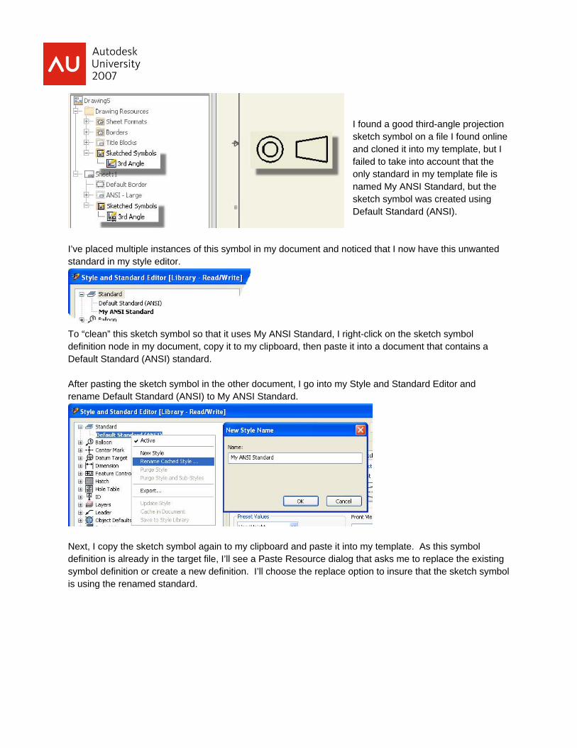
I found a good third-angle projection sketch symbol on a file I found online and cloned it into my template, but I failed to take into account that the only standard in my template file is named My ANSI Standard, but the sketch symbol was created using Default Standard (ANSI).
I’ve placed multiple instances of this symbol in my document and noticed that I now have this unwanted standard in my style editor.
To “clean” this sketch symbol so that it uses My ANSI Standard, I right-click on the sketch symbol definition node in my document, copy it to my clipboard, then paste it into a document that contains a Default Standard (ANSI) standard. After pasting the sketch symbol in the other document, I go into my Style and Standard Editor and rename Default Standard (ANSI) to My ANSI Standard.
Next, I copy the sketch symbol again to my clipboard and paste it into my template. As this symbol definition is already in the target file, I’ll see a Paste Resource dialog that asks me to replace the existing symbol definition or create a new definition. I’ll choose the replace option to insure that the sketch symbol is using the renamed standard.
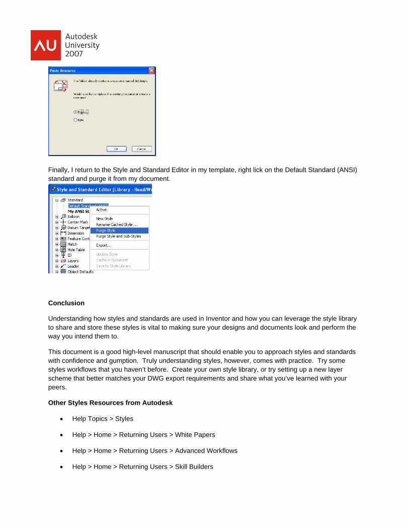
Finally, I return to the Style and Standard Editor in my template, right lick on the Default Standard (ANSI) standard and purge it from my document.
Conclusion
Understanding how styles and standards are used in Inventor and how you can leverage the style library to share and store these styles is vital to making sure your designs and documents look and perform the way you intend them to.
This document is a good high-level manuscript that should enable you to approach styles and standards with confidence and gumption. Truly understanding styles, however, comes with practice. Try some styles workflows that you haven’t before. Create your own style library, or try setting up a new layer scheme that better matches your DWG export requirements and share what you’ve learned with your peers.
Other Styles Resources from Autodesk
• Help Topics > Styles
• Help > Home > Returning Users > White Papers
• Help > Home > Returning Users > Advanced Workflows
• Help > Home > Returning Users > Skill Builders

Skill builders can also be found on the Autodesk Website:
http://usa.autodesk.com/adsk/servlet/autoindex?siteID=123112&id=3365505&linkID=9242016