ray optics modify
DESCRIPTION
Material on Ray opticsTRANSCRIPT

INTRODUCTIONThe branch of physics which deals with the nature of light, its sources, properties, effects and vision is called optics. Light is that form of energy which makes objects visible to our eye.
USESThe science of optics is by far an important part of our life and our economy. It is due to optics that we have discovered our universe from the microscopic virus to the largest galaxy. It is due to optics that we see the colours of a rainbow, sparkling of diamond, twinkling of stars, shining of air bubble in water etc.
NATURE, PROPERTIES AND BEHAVIOR1. Huygen gave wave theory of light. Maxwell showed that light is an electromagnetic wave, which consists of oscillation of electric field and magnetic field perpendicular to each other and perpendicular to direction of propagation in space. 2. The wavelength of light typically varies form 400nm to 700 nm. The limits of the visible spectrum are not well defined because the eye sensitivity curve approaches the axis asymptotically at both long and short wavelengths. This theory explained beautifully reflection, refraction, interference, diffraction and polarization.
Photoelectric effect, Compton effect and several other phenomena associated with emission and absorption of light could not be explained by wave theory. Therefore, quantum theory of light was developed, mainly by Planck and Einstein. At present it is believed that light has dual nature i.e., it propagates as a wave but interacts with matter as a particle.
CLASSIFICATION INTO GEOMETRICAL AND WAVE OPTICS, AND ITS NECESSITYTo make the study of optics easy, it is divided into two parts.
(a) Geometrical or Ray Optics: The phenomena of rectilinear propagation of light, reflection and refraction, are studied in this section.
(b) Wave Optics: The wave behavior of light (like diffraction and interference) is studied in this section. Geometrical optics can be treated as the limiting case of wave optics when size of obstacle or
opening is very much large than the wavelength of light. Under such conditions, wave nature of light can be ignored and light can be assumed to be travelling in straight line (rectilinear propagation). But when size of obstacle or opening is comparable to wavelength of light, rectilinear propagation is no longer valid and resulting phenomena are explained by using wave nature of light.
REFLECTION AND ITS LAWS
When light falls on the surface of a material it is either re-emitted without change in frequency or is absorbed in the material and turned into heat. When the re-emitted light is returned into the same medium from which it comes, it is called reflected light and the process is known reflection.
LAW OF REFLECTION:
OPTICS

2 OPTICS
(I) (I)
(N) (N)
(R) (R)
(P)
i ir r
Reflecting Surface (P)
T T
Note: To apply laws of reflection draw tangent (T) and Normal (N) at the point of reflection (P)
1st Law : Incident ray (I), normal (N) and reflected ray (R) are in same plane.
2nd Law : Angle of incidence = Angle of reflection i r⇒ ∠ = ∠
Mirrors: 1. Plane Mirror 2. Concave Mirror
3. Convex Mirror
REFLECTION AT PLANE SURFACE WITH DIFFERENT EXAMPLES
Image Formation of Point Object by Plane Mirror:
1. Point of intersection of incident light ray is known as object. 2. The point of intersection of reflected rays or refracted ray is known as image.
Note: The object and image may be real or virtual 3. For real object the image formed by plane mirror is virtual.
I M
MO=MI
O
4. For virtual object image formed by plane mirror is real.
MI R
MO=MI
O
Field of view: Region in which diverging rays from object or image are actually present is known as field of view.
Case 1: Field of view for real object

3 OPTICS
Field of view
Field of viewO II
Case 2: Field of view for virtual object
Field of viewO I
Image formation of extended object by plane mirror :
Case 1: Case 2:
A
B
A’
B’
A
B
A’
B’
NGE OF VISION, DEVIATION PRODUCED BY MIRROR
Angle of Deviation: The angle between the direction of incident and reflected (refracted) light ray is known as angle of deviation.
i ir rδ δ
angle of deviation (i r)δ = π − +
Assume i r ,∠ = ∠ = α then (2 )δ = π − α
180º
90º (angle of incidence)
(angle of deviation)
Normal incidence:(N)
(R)(I)
(N)
(R)(I)
i r 0,∠ = ∠ = δ = π
4 OPTICS
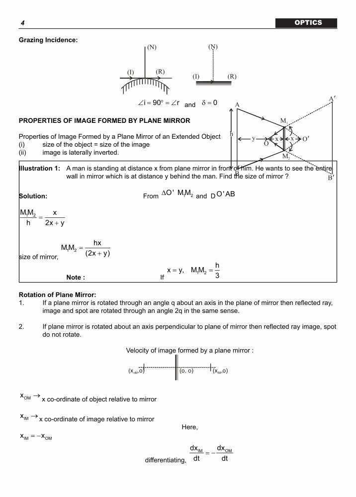
Grazing Incidence:(N)
(R)(I)
(N)
(R)(I)
i 90 r∠ = ° = ∠ and 0δ =
PROPERTIES OF IMAGE FORMED BY PLANE MIRROR
Properties of Image Formed by a Plane Mirror of an Extended Object (i) size of the object = size of the image (ii) image is laterally inverted.
Illustration 1: A man is standing at distance x from plane mirror in front of him. He wants to see the entire wall in mirror which is at distance y behind the man. Find the size of mirror ?
O
A
B
M1
M2
A’
B’
O’h y x x
Solution: From 1 2O ' M M∆ and D O' AB
1 2M M xh 2x y
=+
size of mirror, 1 2
hxM M(2x y)
=+
Note : If 1 2
hx y, M M3
= =
Rotation of Plane Mirror:1. If a plane mirror is rotated through an angle q about an axis in the plane of mirror then reflected ray,
image and spot are rotated through an angle 2q in the same sense.
2. If plane mirror is rotated about an axis perpendicular to plane of mirror then reflected ray image, spot do not rotate.
Velocity of image formed by a plane mirror :
(x ,o)IM(x ,o)oM (o, o)
OMx → x co-ordinate of object relative to mirror
IMx → x co-ordinate of image relative to mirror
Here, IM OMx x= −
differentiating, OMIM dxdx
dt dt= −

5 OPTICS
IM OMv v⇒ = −
⇒ velocity of image relative to mirror = – velocity of object relative to mirror. Illustration 2: Find velocity of image when object and mirror both are moving towards each other with
velocity 2 m/s and 3 ms-1. How they are moving ?
Solution: Here OM IMv v= −
1 1
0 M I M Iv v (v v ) ( 2ms ) ( 3ms ) v ( 3)− −− = − − ⇒ + − − = − + −
1
Iv 8ms−⇒ = −
Combination of Plane MirrorsTo find net deviation produced by combination of plane mirror and deviation produced by each mirror. While adding the deviation ensure that they must be in same direction either clockwise or anticlockwise.
Illustration 3: Two plane mirrors are inclined at 30º as shown in figure. A light ray is incident at angle 45º. Find total deviation produced by combination of mirror after two successive reflection.
30º 45º
M1
Solution: deviation at mirror 1 1M , 180 2 45 90δ = ° − × ° = ° ↑ (clockwise)
deviation at mirror 2 2M ,δ = 180º - 2 × 15º = 150º ¯ (anti clockwise)
total deviation 2 1δ = δ − δ = 150º - 90º = 60º (anti clockwise)IMAGES FORMED BY TWO MIRRORS CASE 1: When the mirrors are parallel to each other
M1 M2
I1’ I2’y
I1
I2
(2x+y)
O x
(2y+x)
y x
Above figure shows image formed by object placed at distance y, from M1 and at distance x from M2. Number of image formed by parallel plane mirrors is infinity.
CASE 2: (when the mirrors are inclined at angle q)
1. All the images formed by two mirrors lie on circle having centre C. Here if angle between mirror is q then image will formed on circle at angle (2p - q). If angle q is less number of image formed will be more. θ
C 2 -π θ
2. If n is number of images, n then

6 OPTICS
(a)
360n 1= −θ If
i 360( ) is even.
360(ii) is odd and object is kept symmetrically
θ θ
(b) If
360n = θ = fractional number then only integral part is taken.
(c)
360n = θ For all other conditions .
Reflection at a spherical surface, paraxial and marginal rays
Spherical mirrors are part of polished spherical surface
Convex mirror
Concave mirror
R
C
PP
1. Center of curvature (C): Center of circle of which mirror is a part. 2. Radius of curvature (R): Radius of circle of which mirror is a part . 3. Pole (P): Centre of mirror reflecting portion 4. Principal axis: Line which join pole to the centre of curvature 5. Diameter of mirror: Shortest distance between two ends of mirror.
Concept of focus:
According to figure,
SCcosiCQ
=
Here RSC 2=
So,
( )R R2CQ CQcosi 2cosi
= ⇒ =
Also,
hsiniR
=
C Q P
ihS i
2iT
When Ri o, CQ 2→ =
and h o→ and TC PC→
Paraxial Ray: Rays whose angle of incidence are small are known as paraxial rays.
Marginal Ray: Rays whose angle of incidence are not small are known as marginal rays.

7 OPTICS
FOCUS, FOCAL PLANE, CENTRE OF CURVATURE, RADIUS OF CURVATURE
Focus:
F Pf
fFP
F = Focus
f = Focal length
If paraxial rays are parallel to the axis of mirror they will meet or appear to meet at a point on the axis, the point is known as focus and the distance between pole and focus is called focal length
Focal plane:
Plane perpendicular to principal axis and passing through focus is known as focal plane
F Primary focus
F Secondary focus’
(i) Rays coming from primary focus will become parallel after reflection.
(ii) Parallel rays of light after reflection will meet at secondary focus.
Centre of curvature:
It is the geometrical centre of the mirror. If light ray passes or appear to pass through centre of curvature then, it retraces its path.
PFC
R
P CF
R
R = Radius of curvature

8 OPTICS
RULES FOR IMAGE FORMATION BY SPHERICAL MIRROR AND RAY DIAGRAM
1. (i) Rays parallel to principal axis passes through focus. (ii) Rays passing through focus goes parallel to principal axis.
C F F
2. Ray passing through center of curvature returns in same path.
C
3. In case of convex mirror for real object, image is erect diminished virtual and between pole and focus
Position, nature and magnification of image and mirror formula
SIGN CONVENTION:
1. Pole is taken as origin and principal axis is taken as x-axis 2. Direction of incident light is taken as direction of +ve x-axis 3. Object, focus, image are referred by their co-ordinates. 4. Height above principal axis is taken as positive.
MIRROR FORMULA:
1 1 1v u f
+ =
1. Mirror formula holds only for paraxial rays.
2. Proof : (for point object and concave mirror)
In CMO i∆ β = + α …(i)
In CMI i∆ γ = + β …(ii) From eqn. (i) and (ii),
( )γ = β − α + β
2⇒ γ = β − α
2⇒ α + γ = β …(iii)
,∴ α β and γ are very small
MP MPtan , tanPO PI
α = α = γ = γ =
and
MPtanPC
β = β =

9 OPTICS
Substitute the value in equation (iii), we will get
M
P I
i
βγ
i
Cα
O
1 1 2PO PI PC
+ =
using, PO u, PI v= − = − and PC R= −
1 1 2( u) ( v) ( R)
⇒ + =− − −
1 1 2v u R
⇒ + =
1 1 2 1 1 1v u 2f v u f
⇒ + = ⇒ + =
Magnification(m):
height of image Imheight of object O
= =
Proof: PAB∆ and PA 'B '∆ are similar
A 'B ' AB A 'B ' PA 'PA ' PA AB PA
= ⇒ =
( I) ( v) I vm( O) ( u) O u
− −⇒ = ⇒ = = −
+ −
1. For Concave mirrors a. If the object is real, the image formed is real and inverted
b. If the object is real, the image formed is virtual and erect.c. If the object is virtual, the image formed is real and erect.
2. For Convex mirrors a. If the object is real, the image formed is virtual and erect. b. If the object is virtual, the image formed is real and erect. c. If the object is virtual, the image formed is virtual and inverted.Methodoffindingco-ordinatesofimageofapointobjectifthecoordinatesofobjectsareknown:

10 OPTICS
Here f, should be substituted with sign Illustration:
Lex
REFRACTION AND ITS LAWS, REFRACTIVE INDEX, SPEED OF LIGHT IN DIFFERENT MEDIA
1. Change in the speed of light as it passes from one medium to other is called refraction
2. Light is deviated due to medium when it is not along the normal
3. Velocity of light in medium
r
r r
Cv = µ →µ ε relative permeability of medium
C → velocity of light in vacuum
rε → relative permitivity of medium
4. Absolute refractive index of medium is defined by
m
CV
µ =V → velocity of light in medium.
SNELL’S LAW:
(N) ® Normal (I) ® Incident Ray (R) ® Refracted Ray
(I) (N)Medium(1)
Medium(2)
r
iµ1
µ2 (R)
11 OPTICS
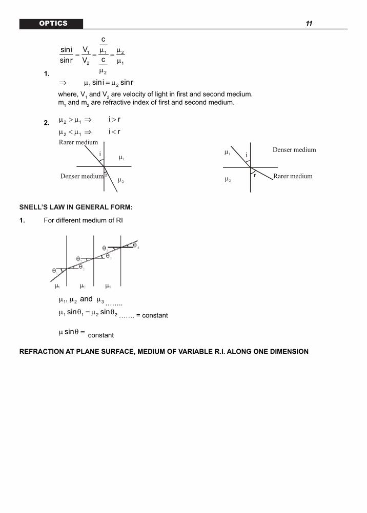
1.
1 1 2
2 1
2
cVsini
csinr Vµ µ
= = =µ
µ
1 2sini sinr⇒ µ = µ
where, V1 and V2 are velocity of light in first and second medium. m1 and m2 are refractive index of first and second medium.
2. 2 1 i rµ > µ ⇒ >
2 1 i rµ < µ ⇒ <
r
i
Denser medium
Rarer medium
µ1
µ2
µ1
µ2r
i
Rarer medium
Denser medium
SNELL’S LAW IN GENERAL FORM:
1. For different medium of RI
1 2 3, and µ µ µ ……..
1 1 2 2sin sinµ θ = µ θ ……. = constant
sinµ θ = constant
REFRACTION AT PLANE SURFACE, MEDIUM OF VARIABLE R.I. ALONG ONE DIMENSION

12 OPTICS
REFRACTION AT PLANE SURFACE
Let us consider the situation as shown in figure. A point object O in medium (1) is viewed from me-dium (2).
Medium (1)
Medium (2)
InterfaceA i
r
IM
O
uv
i
r
From Snell’s law, we have
1 2sini sinrµ = µ …(i) Rays are assumed to be paraxial (i.e., near normal viewing). So i and r are very small
∴ sin i tan i i≈ ≈
sin r tan r r≈ ≈
Hence, equation (i) can be rewritten as
1 2tan i tan rµ = µ
or 1 2
AM AMMO MI
µ = µ
or 1 2
u vµ µ
=− − or
1 2
u vµ µ
=
In general, for refraction at plane surface following relation is used :
i r
u vµ µ
= …(ii)
where, iµ = refractive index of the medium in which incident rays are present
rµ = refractive index of the medium in which refracted rays are present. Particular Case (I): When object is in denser medium and viewed from rarer medium. Using equation (ii), we get
Interface
HH’ I
O
Denser Medium (R.I. = )µD
Rarer Medium (R.I. = )µR
0 R
H vµ µ
=− or R D
Hv −=
µ
∴ R D
HH′ =µ

13 OPTICS also, shift (S) = Real depth (H) – Apparent depth (H’)
or
Particular Case (II): When object is in rarer and viewed from denser medium Using equation (ii), we get
R D
H vµ µ
=−
or R Dv H= − µ
∴ R DH' H= µ
InterfaceH H’
I
O
Denser Medium (R.I. = )µD
Rarer Medium (R.I. = )µR
Also, shift (S) = Apparent height (H’) – Real height (H)
or R DS H( 1)= µ − .
2. If refractive index of a medium is function of x, f(x)µ = then normal should be along x axis.
3. If refractive index of a medium is function of y, f(y)µ = then normal should along y- axis.
Critical angle and T.I.R
i
µR
µDi<θC
i=θCi
µR
µD
µR
µD
i>θC
i
Dµ → Refractive index of denser medium ; Rµ → Refractive index of rarer medium.
1. When a ray propagates from denser medium to rarer medium for 90º angle of refraction corresponding angle of incidence is known as critical angle.
2. At critical angle refraction takes place
RD C R C
D
sin sin90 sin µµ θ = µ ° ⇒ θ =
µ
3. Critical angle does not depend on angle of incidence.REFRACTION THROUGH SLAB AND PRISM, DEVIATIONRefraction through slab:
Let us consider a slab of thickness d and R.I. µ as shown in figure.

14 OPTICS
d
xS
OI1I2
Air SlabAir
Consider refraction at air–slab interface
1x v
µ=
−
or 1v x= −µ
Now, I1 will act as object for refraction at slab–air interface
∴ 2
1(d x) v
µ=
− + µ ⋅
or 2
dv x = − + µ
∴ shift (S)
d 1d x x d 1 = + − + = − µ µ .
1. For real or virtval object the shift will be in the direction of incident wave
2. For multiple slabs, the net shift ‘S’ is given by
Dispersion by Prism: Prism is combination of two plane refracting surface A → angle of prism i → angle of incidence e → angle of emergence δ → angle of deviation
1 2180 A 180 (r r )° − = ° − +

15 OPTICS
1 2A r r⇒ = + …(i)
deviation 1 2 1 2(i r ) (e r )δ = δ + δ = − + −
1 2(i e) (r r )⇒ δ = + − +
Using equation (i), (i e) Aδ = + − …(ii) d-igraph
(angle of incidence)
Minimum Deviation: For minimum deviation i e= ,
So, min
minA2i A i
2δ +
δ = − ⇒ = …(i)
Also, 1 2
Ar r r 2r A r2
= = ⇒ = ⇒ = …(ii)
Using Snell’s law,
1sini sinr= µ min A Asin sin
2 2δ +
⇒ = µ
min( A)sin2Asin2
δ +
⇒ µ =
Maximum Deviation: At maximum deviation e 90= °
and max mini 90 Aδ = + ° −
To find imin in different condition
2 Cr = θ and 1 Cr A= − θ
A
imin er2r1
Using Snell’s law, min Csini sin(A )= µ − θ
[ ]1min Ci sin sin(A )−⇒ = µ − θ
1. If CA 2= θ then mini 90= °

16 OPTICS
2. If CA 2> θ then mini 0>
3. If CA < θ then 4. For mini i 90< < ° light ray comes out. 5. For mini i< T.I.R. occurs.
Thin Prism:
For thin prism A 10≤ °
sini i,= 1 1sinr r ,= 2 2sinr r= , sine e=
and,
1 1
2 2
1sini sinr i rsinr isine e r
= µ ⇒ = µ µ = ⇒ = µ …(i)
deviation 1 2(i e) A (r r ) Aδ = + − ⇒ δ = µ + −
using equation (i) and 1 2r r A, A( 1)+ = δ = µ −
Illustration 4: The cross-section of the glass prism has the form of an isosceles triangle. One of the equal faces is silvered. A ray of light incident normally on the other equal face and after being reflected twice, emerges through the base of prism along the normal. Find the angle of the prism.
Solution:
From the figure,
o90 Aα = −
oi 90 A= − α = …… (i)
Also, o o90 2i 90 2Aβ = − = −
And o90 2Aγ = − β =
Thus, r 2Aγ = =
From geometry,
oA 180+ γ + γ = or o180A 36
5= =

17 OPTICS
Dispersion of Light:
1. The angular splitting of a ray of white light into a number of components and spreading in different direction is called dispersion of light.
2. Angle of Dispersion :
A
θ
Violet
Mean ray (yellow)
Redδr
δyδv
Angle between the rays of the extreme colours in the refracted (dispersed) light is called angle
of dispersion. v rθ = δ − δ
3. Dispersive power ( w) of the medium of the material of prism is given by
y
angular dispersiondeviation of mean ray (yellow)
θω = =
δ
4. For small angled prism A 10≤ °
v v(n 1)Aδ = − R R(n 1)Aδ = − y t(n 1)Aδ = −
here v Rn ,n and yn refractive index of material for violet, red and yellow colours respectively.
y R v R
y y
(n n )(n 1)
δ − δ −ω = =
δ −
If yn is not given in the problem then take
v Ry
n nn2+
=
5. Cause of dispersion :
Dependence of n on l according to cauchy’s formula 2
bn( ) aλ = +λ
Combination of Two Prism: (i) Achromatic Combination :
It is used for deviation without dispersion. For this combination
comb 0θ =
1 1 2 2v R 1 v R 2(n n )A (n n )A− = −
A1
A2
12
Net mean deviation 1 2net y 1 y 2[n 1]A [n 1]Aδ = − − −
1 1 2 2v R v Rnet 1 2
n n n n1 A 1 A
2 2+ −
δ = − − −

18 OPTICS
Also
1net 1
2
1 ω
δ = δ − ω and 1 1 2 2 0ω δ + ω δ = where 1ω and 2ω are depressive powers for the
two prisms and 1δ and 2δ are the mean deviation produced by them.
(ii) Direct vision combination It is used for producing dispersion without deviation, condition for direct vision combination is
A1A2
White light Mean ray
(yellow)
Deviation of mean ray (dy) = 0
1 2y 1 y 2(n 1)A (n 1)A⇒ − = −
1 1 2 2v R v R1 2
n n n n1 A 1 A
2 2+ +
− = −
Net angle of dispersion
1 1 2 2net v R 1 v R 2(n n )A (n n )A⇒ θ = − − −
or 1net y 1 2( )θ = δ ω − ω
REFRACTION AT SPHERICAL SURFACE (PARAXIAL RAY) CHROMATIC ABBERATION
In ∆ OCM, i = α + β …(i)
In ∆ CMI, rβ = + γ …(ii)
According to Snell’s law, 1 2sini sinrµ = µ
For paraxial ray, 1 2i rµ = µ
From eq. (i) and (ii), 1 2( ) ( )µ α + β = µ β − γ
M
P IO Cγα β
r
uv
iµ1µ2
1 2 2 1( )⇒ µ α + µ γ = µ − µ β 1 2 2 1PM PM PM( )PO PI PC
⇒ µ + µ = µ − µ
1 2 2 1( )u v R
µ µ µ − µ⇒ + =
− 2 1 2 1( )
v u Rµ µ µ − µ
⇒ − =
Note: 1. The formula is applicable only for paraxial rays. 2. When surface is plane, R = ∞
2 1
V uµ µ
=
MagnificationbyCurvedSurface:
From Snell’s law, 1 2sini sinrµ = µ
For paraxial rays, 1 2i rµ = µ

19 OPTICS
1 21 2
( O) ( I)OO' II'( )PO PI ( u) v
µ + µ − ⇒ µ = µ ⇒ = − +
So, magnification,
1
2
vImO u
µ= =
µ
O
O’
P
Cir
I
I’u
v
Illustration 5: A linear object of length 4 cm is placed at 30 cm from the plane surface of hemispherical glass of radius 10 cm. The hemispherical glass is surrounded by water. Find the final position and size of the image
Solution: For 1st surface 1 2
4 3, ,u 203 2
µ = µ = = − cm,
and R 10= + cm,
using 2 1 2 1( )
v u Rµ µ µ − µ
− =
( ) ( ) ( )3 34 42 3 2 3
v ( 20) 10
−⇒ − =
−
v 30⇒ = − cm Using
( )( )
1
2
4 ( 30)vA 'B ' A 'B ' 33AB u (4cm) ( 20)2
−µ= ⇒ =
µ −
4cmA’
B’ B
A
B”
A’
1 surfacest
uv
u’v’
5.3cm 5.3cm

20 OPTICSA 'B ' 5.3⇒ = cm.
A 'B ' behaves as the object for plane surface
' '1 2
3 4,2 3
µ = µ = and R , u' 40= ∞ = −
( ) ( )' '2 1
343 2
v ' u ' v ' ( 40)µ µ
⇒ = ⇒ =−
Solving it we will get, v ' 25.4= − cm
Now using,
( )( )
'1
'2
vA "B"A 'B ' u
µ=
µ
( ) ( )
( ) ( )
3 35.4A "B" 2 A "B" 5.34(5.3) 403
−⇒ = ⇒ =
− cm
The final images in all the above cases are shown in figure.
30cm
20cm
Right
µ = 4/3
C A
µ = 1
P
Left BD
O15cm
Illustration 6: The slab of a material of refractive index 2 shown in figure has a curved surface APB of radius of curvature 10 cm and a plane sur-face CD. On the left of APB is air & on the right of CD is water with refractive indices as given in the figure. An object O is placed at a distance of 15 cm from the pole P as shown. What is the distance of final image of O from P as shown. What is the distance of final image of O from P as viewed from the left?
Solution: In case of refraction from a curved surface, we have
Here ; R = - 10 cm and u = - 15 cm
So
1 2 1 2 , i.e., 30cm( 15) 10
−− = ν = −
ν − −i.e., the curved surface will form virtual image I at a distance of 30 cm from P. Since, the image is virtual there will be no refraction at the plane surface CD (as the rays are not actually passing through the bound-ary), the distance of final image I from P will remain 30 cm.
THIN LENS AND ITS PROPERTIES
1. A lens is a homogenous transparent medium (such as glass) bounded by two curved surfaces or one curved and a one plane surface.

21 OPTICS
Types of Lens:
Assume 1 2R and R are Radius of curvature of first and second surface.
(i) Biconvex Lens (ii) Plano convex lens
(iii) Biconcave Lens (iv) Plano concave lens
(v) Concavo convex lens
2. Centre most point (P) of lens is known as optical centre
3. Line joining both the center of curvature and optical center is called principal axis.
(I) Real focus: (2nd focus, Main focus)
converging point of parallel beam of light is known as real focus (u , v f )= ∞ =
F2
f2
f2
F2
(II) 1st Focus: If ray coming from a point or converging to a point after refraction become parallel then the point is known as 1st focus.
f1
F1
f1
F1
Note: (1) For convex lens 2 1f ve, f ve= + = − (2) For concave lens 2 1f ve, f ve= − = +
REFRACTION THROUGH THIN LENS

22 OPTICS
FC
f
(a) Refraction through a convex lens
Focal Plane
FC
f(b) Refraction through a
concave lens
Focal Plane
LENS MAKER FORMULA, POWER OF LENS LensMaker’sFormula:
sµ → refractive index of surrounding.
lµ → refractive index of lens
For surface of radius R1:
µ µ − µµ− =s l sI
1
( )v ' u R …(i)
and for surface of radius R2 :
s s ll
2
( )v v ' R
µ µ − µµ− =
…(ii) adding equation (i) and (ii)
l s
s 1 2
( )1 1 1 1v u R R
µ − µ ⇒ − = − µ
l
s 1 2
1 1 1 11v u R R
µ− = − − µ …(iii)
If u = ∞ then v f=
− −
l
s 1 2
ì1 1 1= 1fì R R (LensMaker’sFormula) …(iv)
From equation (iii) and (iv)
1 1 1= -f v u ® Lens Formula
Note: (Condition for application of Len’s makers formula)
P Q C P1 Q1

23 OPTICS 1. Medium on both sides of lens should be same 2. Lens should be thin 3. Light rays should be paraxial
POWER OF LENS
Power of a lens is defined as the ratio of the refractive index of the surrounding medium and the focal length of the lens in that medium f. The unit of power is dioptre.
Mathematically it can be written as
ìP =f . [f in metre]
RULES FOR IMAGE FORMATION AND MAGNIFICATION ETC. RAY DIAGRAM
Position and Nature of Image formed for a given Position of Object. The following rules are used for image formation in case of thin lenses : (i) A ray passing through optical centre proceeds undeviated through the lens as shown in figure.
C
(a)
C
(b) (ii) A ray passing parallel to the principal axis after refraction through the lens passes or appears to
pass through second focal point as shown in figure.
(a)
f
F2
C
C
(b)f
F2
(iii) A ray passing through first focus or directed towards first focus, after refraction from the lens becomes parallel to the principal axis as shown in figure.
(a)
fF1 C
C
(b)
f
F1
Magnification:
This is defined as the ratio of size of image to the size of object.
Size of image (I)Magnification (m) =Size of object (O)
(a) TransverseorLateralmagnification(mT) It is defined as the ratio of any transverse dimension of the image to the corresponding transverse
dimension of the object. Let the size of the object and image be denoted by O and I respectively.
T
ImO
=.
(b) It is defined as the ratio of the length of the image to the corresponding length of the object.

24 OPTICS
P QL
P Q
v vm
u u−
=−
For small object, L
dvmdu
=
Differentiating lens equation, we get
2 2
dv du 0v v
− − − = or
2 2
dv du 0v u
− =
and therefore,
222
L 2
dv v vm mdu uu
= = = =
Therefore, for small object longitudinal magnification is square of transverse magnification.
(a) For Convergent or Convex Lens S.No.PositionofObject Ray-Diagram DetailsofImage
1. At infinity Real, inverted, Diminished (m << -1) at F
F1
F2
2. Between infinity and 2F Real, inverted, Diminished (m < -1) between F and 2F
IO
3. At 2F Real, inverted, Equal m = -1 at 2F
IO
4. Between 2F and F Real, inverted, Enlarged (m >-1) between 2F and infinity
IO2F F
2FF
5. At F Real, inverted, Enlarged (m >>-1) at infinity.
O2F F
F 2F

25 OPTICS 6. Between F and O Virtual Erect Enlarged (m>>-1)
2F FF 2F
(b) For Divergent or Concave Lens
S.No.PositionofObject Ray-Diagram DetailsofImage
1. At infinity Virtual, inverted, very small (m << -1), at F
F
2. Between F and optical centre Near Lens Virtual, Erect Diminished (m<+1)
F IO
Sign Convention:Focal length of converging lens is taken as positive and that of the diverging lens is taken as negative, if it is kept in vacuum or in a medium whose refractive index is less than the lens. 1. For convex lens a) If object is real, image formed is real & inverted b) If object is real, image formed is virtual & erect c) If object is virtual, image formed is real & erect 2. For concave lens a) If object is real, image formed is virtual of erect b) If object is virtual, image formed is real & erect c) If object is virtual, image formed is virtual & inverted
COMBINATION OF LENSES Equivalent Focal Length of Combination of Lenses: If number of lenses of focal lengths are placed coaxially in contact then the equivalent focal length
of the combination is given by
1 2 n
1 1 1 1.....F f f f
= + + + ...(iii)
In terms of power 1 2 nP p p ..... p= + + +
SILVERING OF LENSES
When a lens is silvered, it behaves like a spherical mirror whose power eq(P ) is given by
eq iP P= Σ

26 OPTICS
where Pi is the power of lens or mirror to be taken as many times as the number of refraction or reflection. For example, let us consider silvered equiconvex lens then
eq L MP 2P P= +
as final image is formed after three optical events involving two refraction through lens and one reflection at plane mirror. The focal length of equivalent spherical mirror is given by
eq
eq
1fP
= −
If feq is –ve then mirror is concave and, if feq is +ve, then mirror is convex.
FORMATION OF IMAGE BY DISPLACEMENT METHOD
In this method, an object and a screen are placed at a distance a apart. A convex lens of focal length f(f < a/4) can be placed in two position between the object and the screen such that a real image of the same object is formed on the screen in both the positions.
A
B Screen
A'
B'
B"
u vV
ad
u
Let a be the distance between the object and the screen and let d be the distance between the two position of the lens. From the figure :
u + v = a v – u = d
Solving, we get
a d a dv , u2 2+ −
= =
Using the lens formula and simplifying, we get
2 2a df4a−
= ...(i)
Let 1 2I A 'B '; I A 'B ; O AB′′= = =
1
1I a dmO a d
+= =
− i.e. the one image is larger than the object
2
2I a dmO a d
−= =
+ i.e. the other image is shorter than the object
\ 1 2O I I= ...(ii) i.e. the size of the object is the geometric mean of the sizes of the two images.

27 OPTICSIllustration 7: For two positions of a converging lens between an object and a screen which are 96 cm apart,
two real images are formed. The ratio of the lengths of the two images is 4.84. Calculate the focal length of the lens.
Solution: Here
1
2
m 4.84m
= ⇒
2a d 4.84a d
+ = − ⇒
a d 2.2a d 1
+=
− Putting a = 96 cm gives d = 36 cm
2 2a df 20.6254a−
∴ = =cm .
KEY CONCEPTS Light is said to move rectilinearly if, a D>> λ
Mirror formula.
1 1 2 1v u R f
+ = =
Newton’s Formula. XY = f2
Optical power of a mirror (in Diopters) = −
m
1f ; fm is meter.
Laws of refraction.
2 1 1
1 2 2
n vsinisinr n v
λ= = =
λ
Refractive index of the medium relative of vacuum r r= µ ∈
Deviation (d) of ray incident at i∠ and refracted at
r∠ is given by | i r |δ = −
Principle of Reversibility of light Rays.
1 2
2 1
1nn
=
Refraction through a Parallel Slab
( )t sin i rd
cosr−
=
Apparent Depth and shift of Submerged object.
Apparent shift rel
1d 1n
= −
Refraction through a Composite Slab
Apparent shift = 1 2 n
1rel 2rel n rel
1 1 nt 1 t 1 .... 1 tn n n
− + − + + −
CriticalAngleandTotalInternalReflection(T.I.R.).
1 r
d
nC sinn
−=
Angle of deviation. d = i + e – A Angle of dispersion. q = dv – dr

28 OPTICS
Cauchy’s formula.
( ) 2
bn aλ = +λ
Dispersive power
v r
y
n nn 1
−ω =
−
Dispersion without deviationThe condition for direct vision combination is.
y yn 1 A n 1 A′ ′ − = − ⇔
v rn n 12+ −
v rn nA 1 A2
′ ′+ ′= −
Deviation without dispersion Condition for achromatic combination is.
( ) ( )v r v rn n A n n A′ ′ ′− = −
Spherical Surfaces
2 1 2 1n n n n
v u R−
− =
Transversemagnification
2
1
v / nv Rmu R u / n
−= = −
Refraction at plane Surface
2
1
n uvn
=
For a spherical, thin lens having the same medium on both sides.
( )rel
1 2
1 1 1 1n 1v u R R
− = − −
… (a)
when
lensrel
medium
nnn
=
Transversemagnification(m)
vmu
=
Lens formula
1 1 1v u f
− =
The equivalent focal length of thin lenses in contact is given by
1 2 3
1 1 1 1F f f f
= + +….
The combination of lens and mirror behaves like a mirror of focal length ‘f’ given by
m
1 1 2f F F
= −

29 OPTICSCONCEPTUAL QUESTIONS
1. A thick plane mirror shows a number of images of the filament of an electric bulb. Of these, the brightness image is the
(a) first (b) second (c) fourth (d) last.
2. A light beam is being reflected by using two mirrors, as in a periscope used in submarines. If one of the mirrors rotates by an angle θ , the reflected light will deviate from the original path by the angle
(a) 2θ (b) 0º (c) θ (d) 4θ .
3. A convex mirror is used to form the image of an real object. Then which of the following statements is wrong
(a) the image lies between the pole and the focus (b) the image is diminished in size (c) the image is erect (d) the image is real.
4. All the following statements are correct except (a) A real, inverted same sized image can be formed using convex mirror (b) The magnification produced by a convex mirror is always less than one (c) A virtual erect and same sized image can be obtained using a plane mirror (d) A virtual, erect, magnified image can be formed using a cancave mirror
5. When light travels from one medium to the other which the refractive index is different, then which of the following will change
(a) frequency, wavelength and velocity (b) frequency and wavelength (c) frequency and velocity (d) wavelength and velocity.
6. Light of different colours propagates through air (a) with the velocity of air (b) with different velocities (c) with the velocity of sound (d) having the equal velocities.
7. A cut diamond sparkles because of its (a) hardness (b) high refractive index (c) emission of light by the diamond (d) absorption of light by the diamond.
8. A diver in a swimming pool wants to signal his distress to a person lying on the edge of the pool by flashing his water proof flash light
(a) he must direct the beam vertically upwards (b) he has to direct to the beam horizontally (c) he has to direct the beam at an angle to the vertical which is slightly less than the critical angle
of incidence for total internal reflection (d) he has to direct the beam at an angle to the vertical which is slightly more than the critical angle
of incidence for total internal reflection.
9. When white light passes through a glass prism, one gets spectrum on the other side of the prism. In the emergent beam, the ray which is deviating least is or deviation by a prism is lowest for
(a) violet ray (b) green ray (c) red ray (d) yellow ray.
10. We use flint glass prism to disperse polychromatic light because light of different colours

30 OPTICS (a) travel with same speed (b) travel with same speed but deviate differently due to the shape of the prism (c) have different anisotropic properties while travelling through the prism (d) travel with different speeds.
11. A glass lens is placed in a medium in which it is found to behave like a glass plate. Refractive index of the medium will be
(a) greater than the refractive index (b) smaller than the refractive index of glass (c) equal to refractive index of glass (d) no case will be possible from above.
12. A biconvex lens from a real image of an object placed perpendicular to its principal axis. Suppose the radii of curvature of the lens tend to infinity. Then the image would
(a) disappear (b) remain as real image still (c) be virtual and of the same size as the object (d) suffer from aberrations.
KEY
1. (b) 2. (a)
3. (d) 4. (a) 5. (d) 6. (d)
7. (b) 8. (c)
9. (c) 10. (c)
11. (c) 12. (c)CINTSHI
HINTS AND SOLUTIONS
1. Several images will be formed but second image will be brightest
90%
10%
100%
9%
Incident light
First image
Second brightestimage
Third image10%
90%
10% 80%
10%
.2. When a mirror is rotated by an angle θ , the reflected ray deviate from its original path by angle 2θ .3. The image formed by a convex mirror is always virtual.4. Convex mirror can produce real & erect or virtual & inverted.5. Velocity and wavelength change but frequency remains same.6. In vacuum, the speed of light is independent of wave length. Thus vacuum (or air) is a non dispersive
medium in which all colours travel with the same speed.7. Due to high refractive index its critical angle is very small so that most of the light incident on the diamond
is total internally reflected repeatedly and diamond sparkles.8. When incident angle is greater than critical angle, then total internal reflection takes place and will come

31 OPTICSback in same medium.
9. R( 1)δ ∝ µ − ⇒ µ is least so Rδ is least.10. Conceptual
11.
a gI
a I g
( 1)ff ( 1)
µ −=
µ −
1f⇒ = ∞ if I g 1µ =
a I a g⇒ µ = µ.
12. 1 2
1 1 1( 1)f R R
= µ − −
For biconvex lens 2 1R R= −
1 2( 1)f R
∴ = µ −
Given R f= ∞ ∴ = ∞ , so no focus at real distance.
LEVEL – IMODEL QUESTIONS
SINGLE CHOICE CORRECT QUESTIONS
1. A concave mirror is placed on a horizontal table, with its axis directed vertically upwards. Let O be the pole of the mirror and C its centre of curvature. A point object is placed at C. It has a real image, also located at C. If the mirror is now filled with water, the image will be
(a) real and will remain at C (b) real and located at a point between C and ∞ (c) virtual and located at a point between C and O (d) real and located at a point between C and O.
2. A ray of light passes through four transparent media with refractive indices 1 2 3, ,µ µ µ and 4µ as shown in the figure, the surfaces of all media are parallel. If the emergent ray CD is parallel to the incident ray AB, we must have
(a) 1 2µ = µ (b) 2 3µ = µ
(c) 3 4µ = µ (d) 4 1µ = µ .

32 OPTICS3. A ray of light passes through an equilateral prism such that the angle of incidence and the angle of
emergence are both equal to 3/4th of the angle of prism. The angle of minimum deviation is (a) 15º (b) 30º (c) 45º (d) 60º.
4. A ray of light falls on a transparent glass slab with refractive index (relative to air) of 1.62. The angle of incidence for which the reflected and refracted rays are mutually perpendicular is.
(a) 1tan (1.62)−
(b) 1sin (1.62)−
(c) 1cos (1.62)−
(d) none of these.
5. A 4.0 cm thick water layer ( 4 / 3)µ = rests on a 6.0 cm layer of 4CCl ( 1.5)µ = in a tank. How far below the water surface, viewed normally from above, does the bottom of the tank seem to be
(a) 7.0 cm (b) 8.0 cm (c) 9.0 cm (d) 10.0 cm.
6. Which one of the following spherical lenses does not exhibit dispersion? The radii of curvature of the surfaces of the lenses are as given in the diagrams
(a)
R1 R2
21 RR ≠ (b)
R
(c)
R R
(d)
R
.
7. A lens of focal length f projects m times magnified image of an object on a screen. The distance of the screen from the lens is
(a)
f(m 1)− (b)
f(m 1)+
(c) f(m 1)− (d) f(m 1)+ .
8. A thin equiconvex lens of refractive index 3/2 and radius of curvature 30 m is put in water (refractive
index
43
=). Its focal length is
(a) 0.15 m (b) 0.30m (c) 0.45 m (d) 1.20 m.
9. A 16 cm long image of an object is formed by a convex lens on a screen. On moving the lens towards the screen, without changing the positions of the object and the screen, a 9 cm long image is formed again on the screen. The size of the object is
(a) 9 cm (b) 11 cm (c) 12 cm (d) 13 cm.
10. Two lenses, one concave and the other convex of same power are placed such that their principal axes coincide. If the separation between the lenses is x, then
(a) real image is formed for x = 0 only (b) real image is formed for all values of x (c) system will behave like a glass plate for x = 0 (d) virtual image is formed for all values of x other than zero.

33 OPTICSMAY BE MORE THAN ONE CORRECT CHOICE ANSWERS
11. For which of the pairs of u and f for a mirror image is smaller in size. (a) u = – 10 cm, f = 20 cm (b) u = – 20 cm, f = – 30 cm (c) u = – 45 cm, f = – 10 cm (d) u = – 60 cm, f = 30 cm
12. There are three optical media 1, 2 and 3 with their refractive indices 1 2 3µ > µ > µ . (TIR – total internal reflection) (a) when a ray of light travels from 3 to 1 no TIR will take place (b) critical angle between 1 and 2 is less than the critical angle between 1 and 3 (c) critical angle between 1 and 2 is more than the critical angle between 1 and 3 (d) chances of TIR are more when ray of light travels from 1 to 3 as compare to the case when it
travel from 1 to 2
13. A ray of light is incident in situation as shown in figure which of the following statements is/are true?
30ºµ1=4
µ2
µ3=2
(I) if then angle of deviation is 60º
(II) if then angle of deviation is 60º
(III) if then angle of deviation is 120º
(IV) if then angle of deviation is zero (a) I and IV (b) III and I (c) II and IV (d) none
14. In the figure light is incident at angle which is slightly greater than the critical angle. Now, keeping the incident ray fixed a parallel slab of refractive index n3 is placed on surface AB. Which of the following statements are correct .
A Bn2
n <n1 2
θ
(a)
n1
A Bn2 θ
(b)
n3
n1C D
(a) total internal reflection occurs at AB for n3 < n1 (b) total internal reflection occurs at AB for n3 > n1 (c) the ray will return back to the same medium for all values of n3 (d) total internal reflection may occur at CD for n3 > n1
15. For refraction through a small angled prism, the angle of minimum deviation .
(a) increases with the increases in R.I. of the prism

34 OPTICS
(b) will be 2D for a ray of R.I. 2.4, if it is D for a ray of R.I. 1.2
(c) is directly proportional to the angle of the prism
(d) will decrease with the increase in R.I. of the prism
16. Parallel rays of light are falling on convex spherical surface of radius of curvature R = 20 cm as
shown. Refractive index of the medium is 1.5µ = . After refraction from the spherical surface parallel rays
(a) actually meet at some point (b) appears to meet after extending the refracted rays backwards (c) meet (or appears to meet) at a distance of 30 cm from the spherical surface (d) meet (or appears to meet) at a distance of 60 cm from the spherical surface
17. A point object is placed at 30 cm from a convex glass lens S
32
µ = of focal length 20 cm. The final
image of object will be formed at infinity if (a) another concave lens of focal length 60 cm is placed in contact with the previous lens (b) another convex lens of focal length 60 cm is placed at a distance of 30 cm from the first lens (c) the whole system is immersed in a liquid of refractive index 4/3 (d) the whole system is immersed in a liquid of refractive index 9/8
18. The radius of curvature of the left and right surface of the concave lens are 10 cm and 15 cm respec-tively. The radius of curvature of the mirror is 15 cm .
(a) equivalent focal length of the combination is – 18 cm
(b) equivalent focal length of the combination is + 36 cm
(c) the system behaves like a concave mirror
(d) the system behaves like a convex mirror
COMPREHENSION
@ Write-up–1
A ray of light enters a spherical drop of water of refractive index m as shown in the figure.
φ
αA
19. Select the correct statement . (a) Incident rays are partially reflected at point A. (b) Incident rays are totally reflected at point A. (c) Incident rays are totally transmitted through A. (d) None of these.

35 OPTICS
20. An expression of the angle between incidence ray and emergent ray (angle of deviation) as shown in the figure is
φ
αA
(a) 0º (b)
(c) (d)
21. Consider the figure of previous question the angle for which minimum deviation is produced will be given by
(a)
22 1cos
3µ +
φ = (b)
22 1cos
3µ −
φ =
(c)
22 1sin
3µ +
φ = (d)
22 1sin
3µ −
φ =.
@ Write-up–2
Magnification by a lens of an object at distance 10 cm from it is – 2. Now a second lens is placed exactly at the same position where first was kept, without changing the distance between the object and lens. The magnification by this second lens is – 3.
22. Now both the lens are kept in contact at the same place. What will be the new magnification? (a) – 13/5 (b) – 12/7 (c) – 6/11 (d) – 5/7
23. What is the focal length of the combination when both lenses are in contact ?
(a)
60 cm17 (b)
5 cm17
(c)
12 cm7 (d)
13 cm9
24. What is the focal length for the first lens (a) 10 cm (b) 20 cm (c) 20/3 cm (d) 10/3 cm
ASSERTION / REASONCodes. (a) Statement – 1 is True, Statement – 2 is True; Statement – 2 is a correct explanation for State-
ment – 1. (b) Statement – 1 is True, Statement – 2 is True; Statement – 2 is Not a correct explanation for State-
ment – 1. (c) Statement – 1 is True, Statement – 2 is False. (d) Statement – 1 is False, Statement – 2 is True.
25. STATEMENT – 1 For all types of mirrors, object and image always move in opposite directions. STATEMENT – 2 Speeds of object and image are equal for a stationary plane mirror.

36 OPTICS26. STATEMENT – 1
For a prism of refracting angle 60º and refractive index 2 , minimum deviation is 30º. STATEMENT – 2
At minimum deviation,
mA Dsin2Asin2
+
µ =
; where the symbols have their usual meanings
27. STATEMENT – 1 When light travels from denser to rarer medium the critical angle of incidence have different values for different wavelengths of light.
STATEMENT – 2 Refractive index of a medium varies with wavelength of light.
28. STATEMENT – 1 White light splits into seven colours when refraction occurs even at single surface. STATEMENT – 2 For different wavelength angles of refraction are different, as their corresponding refractive indices
are different.
29. STATEMENT – 1 The focal length of a thin converging lens, made of glass, for violet light is fv, while that for red light is
fr, these satisfy the relation . fr > fv. STATEMENT – 2 The refractive index of the material of the lens (glass) satisfies mv > mr;
and 1 2
1 1 1( 1)f R R
= µ − −
applies to the lens.MATRIX MATCHEach question contains statements given in two column which have to be matched. Statements (a, b, c, d) in Column A have to be matched with statements (p, q, r, s) in Column B. The answers to these questions have to be appropriately bubbled as illustrated in the following example.
30. A real object is being seen by optical component listing in column A and nature of image of this object is listing in column B .
Column – A Column – B Nature of image (a) Convex lens. (p) Real. (b) Convex mirror. (q) Virtual. (c) Concave lens. (r) Erect. (d) Concave mirror. (s) Inverted.
31. Column–B shows the optical phenomenon that can be associated with optical components given in Column–A. Note the Column–I may have more than one matching options in Column–B.
Column – A Column – B (a) Convex mirror. (p) Dispersion. (b) Converging lens. (q) Deviation. (c) Thin prism. (r) Real image of real object. (d) Glass slab. (s) Virtual image of real object.
PRACTICE QUESTIONS
37 OPTICS
QP R
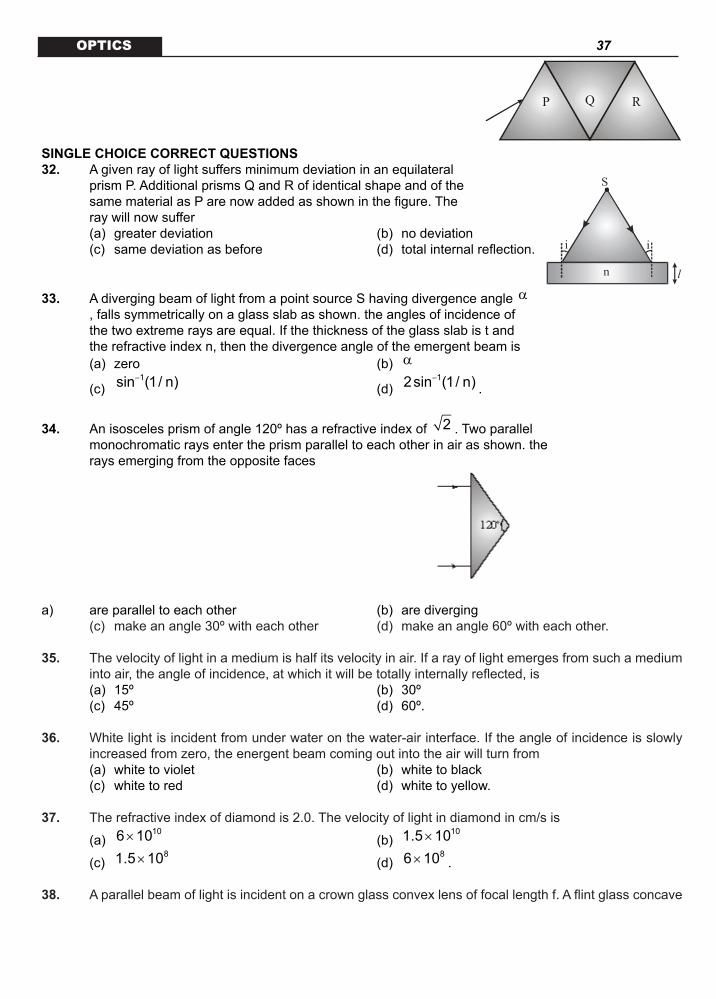
SINGLE CHOICE CORRECT QUESTIONS32. A given ray of light suffers minimum deviation in an equilateral
prism P. Additional prisms Q and R of identical shape and of the same material as P are now added as shown in the figure. The ray will now suffer
(a) greater deviation (b) no deviation (c) same deviation as before (d) total internal reflection.
n
S
i
l
i
33. A diverging beam of light from a point source S having divergence angle α, falls symmetrically on a glass slab as shown. the angles of incidence of the two extreme rays are equal. If the thickness of the glass slab is t and the refractive index n, then the divergence angle of the emergent beam is
(a) zero (b) α
(c) 1sin (1/ n)−
(d) 12sin (1/ n)−
.
34. An isosceles prism of angle 120º has a refractive index of 2 . Two parallel monochromatic rays enter the prism parallel to each other in air as shown. the rays emerging from the opposite faces
a) are parallel to each other (b) are diverging (c) make an angle 30º with each other (d) make an angle 60º with each other.
35. The velocity of light in a medium is half its velocity in air. If a ray of light emerges from such a medium into air, the angle of incidence, at which it will be totally internally reflected, is
(a) 15º (b) 30º (c) 45º (d) 60º.
36. White light is incident from under water on the water-air interface. If the angle of incidence is slowly increased from zero, the energent beam coming out into the air will turn from
(a) white to violet (b) white to black (c) white to red (d) white to yellow.
37. The refractive index of diamond is 2.0. The velocity of light in diamond in cm/s is
(a) 106 10× (b)
101.5 10×
(c) 81.5 10× (d)
86 10× .
38. A parallel beam of light is incident on a crown glass convex lens of focal length f. A flint glass concave

38 OPTICSlens of the same focal length is placed in contact with it. The image will now be formed at
(a) f (b) between f and 2f (c) 2f (d) infinity.
39. A thin double convex lens has radii of curvature each of magnitude 40 cm and is made of glass with 1.5µ = . The focal length of the lens is
(a) 30 cm (b) 31 cm (c) 40 cm (d) 41 cm.
40. A hollow double concave lens is made of very thin transparent material. It can be filled with air or either
of two liquids L1 or L2 having refracting indices n1 and n2 respectively 2 1(n n 1)> > . The lens will diverge a parallel beam of light if it is filled with
(a) air and placed in air. (b) air and immersed in (c) L1 and immersed in L2 (d) L2 and immersed in L1.
MLAY BE MORE THAN ONE CORRECT CHOICE ANSWERS
41. A plane mirror M is arranged parallel to a wall W at a distance from it. The light produced by a point source S kept on the wall is reflected by the mirror and produces a light spot on the wall. The mirror moves with velocity n towards the wall. Then.
(a) The spot of light will move with the speed n on the wall. (b) The spot of light will not move on the wall. (c) As the mirror comes closer, the spot of light will becomes larger and shift ways from the wall with speed larger then n. (d) The size of the light spot on the wall remains the same.
42. Two points P and Q lie on either side of an axis XY as shown. It is desired to produce an image of p at Q using a spherical mir-ror, with XY as the optic axis. The mirror must be
(a) converging and positioned to the left of P (b) diverging and positioned to the left of P (c) converging and positioned to the right of Q (d) diverging and positioned to the right of Q.43. The deviation produced by a prism depends on
(a) the angle of incidence of light on its face (b) the refracting angle of prism

39 OPTICS (c) the refractive index of the prism
(d) the wavelength of the light used.
44. In the figure, a ray of light falls on face 1 of a piece of glass (refrac-tive index = m) kept in air. Faces 1 and 3 are planar, and the ray is not intercepted by faces 2 and 4. The angle(s) independent of m is/are
(a) i + i’ + d (b) i + i’ – d
(c)
i i '2+
(d)
i i '2+
– d
45. For the refraction of light through a prism. (a) For every angle of deviation there are two angles of incidence (b) the light traveling inside and equilateral prism is necessarily parallel to the base when prism is
set for minimum deviation (c) There are two angles of incidence for maximum deviation (d) Angle of minimum deviation will increase if refractive index of prism is increased keeping the
outside medium unchanged and if mp > ms.
46. A diminished image of an object is to be obtained on a screen 1.0 m away from it. This can be achieved by approximately placing
(a) a convex mirror of suitable focal length (b) a concave mirror of suitable focal length (c) a convex lens of focal length less than 0.25 m (d) a concave lens of suitable focal length.
47. An image of a bright square is obtained on a screen with the aid of a convergent lens. The distance between the square and the lens is 40 cm. The area of the image is nine time larger than that of the square. Select the correct statement(s) .
(a) Image is formed at a distance 120 cm from lens. (b) Image is formed at a distance 360 cm from lens. (c) Focal length of lens is 30 cm. (d) Focal length of lens is 36 cm.
48. A lens of focal length ‘f’ is placed in between an object and screen separated by a distance ‘D’. The lens forms two real images of object on the screen for two of its different positions, a distance ‘x’ apart. The two real images have magnifications m1 and m2 respectively (m1> m2).
(a) 1 2
xfm m
=− (b) m1m2 = 1
(c)
2 2D xf4D−
= (d) D ³ 4f.
49. Consider the rays shown in the diagram as paraxial. The image of the virtual point object O formed by the lens LL is
40 OPTICS (a) Virtual. (b) Real. (c) Located below the principal axis. (d) Located left of the lens.
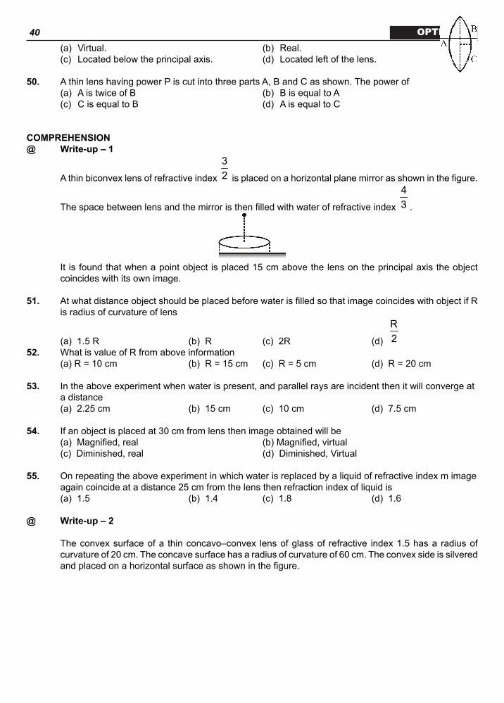
50. A thin lens having power P is cut into three parts A, B and C as shown. The power of (a) A is twice of B (b) B is equal to A (c) C is equal to B (d) A is equal to C
COMPREHENSION@ Write-up–1
A thin biconvex lens of refractive index
32 is placed on a horizontal plane mirror as shown in the figure.
The space between lens and the mirror is then filled with water of refractive index
43 .
It is found that when a point object is placed 15 cm above the lens on the principal axis the object coincides with its own image.
51. At what distance object should be placed before water is filled so that image coincides with object if R is radius of curvature of lens
(a) 1.5 R (b) R (c) 2R (d)
R2
52. What is value of R from above information (a) R = 10 cm (b) R = 15 cm (c) R = 5 cm (d) R = 20 cm
53. In the above experiment when water is present, and parallel rays are incident then it will converge at a distance
(a) 2.25 cm (b) 15 cm (c) 10 cm (d) 7.5 cm
54. If an object is placed at 30 cm from lens then image obtained will be (a) Magnified, real (b) Magnified, virtual (c) Diminished, real (d) Diminished, Virtual
55. On repeating the above experiment in which water is replaced by a liquid of refractive index m image again coincide at a distance 25 cm from the lens then refraction index of liquid is
(a) 1.5 (b) 1.4 (c) 1.8 (d) 1.6
@ Write-up–2
The convex surface of a thin concavo–convex lens of glass of refractive index 1.5 has a radius of curvature of 20 cm. The concave surface has a radius of curvature of 60 cm. The convex side is silvered and placed on a horizontal surface as shown in the figure.

41 OPTICS
56. The focal length of the combination has the magnitude (a) 8.6 cm (b) 7.5 cm (c) 1.5 cm (d) 15 cm
57. The combination behaves like (a) a concave mirror (b) a convex mirror (c) a concave lens (d) a convex lens
58. A small object is placed on the principal axis of the combination, at a distance of 30 cm in front of the mirror. The magnification of the image is
(a)
13
− (b)
34
(c) 5 (d) none of these.
ASSERTOPM / REASON
Codes. (a) Statement – 1 is True, Statement – 2 is True; Statement – 2 is a correct explanation for State-
ment – 1. (b) Statement – 1 is True, Statement – 2 is True; Statement – 2 is NOT a correct explanation for
Statement – 1. (c) Statement – 1 is True, Statement – 2 is False. (d) Statement – 1 is False, Statement – 2 is True.
59. STATEMENT-1 Geometrical optics can be regarded as the limiting case of wave optics. STATEMENT-2 When size of obstacle or opening is very large compared to the wavelength of light then wave nature
can be ignored and light can be assumed to be traveling in straight line.
60. STATEMENT-1 Virtual images cannot be photographed. STATEMENT-2 Rays from virtual image are diverging. 61. STATEMENT-1 Virtual object can’t be seen by human eye. STATEMENT-2 Virtual object is formed by converging rays.
62. STATEMENT-1 A convex mirror is used as rear view mirror. STATEMENT-2 Convex mirror always forms virtual, erect and diminished image.

42 OPTICS
63. STATEMENT-1 The behavior of any lens depends on surrounding medium. STATEMENT-2 A lens can be looked upon as a collection of small prisms with varying prism angle.
MATRIX MATCHEach question contains statements given in two column which have to be matched. Statements (a, b, c, d) in Column A have to be matched with statements (p, q, r, s) in Column B. The answers to these questions have to be appropriately bubbled as illustrated in the following example.
64. A ray of light strikes at the boundary separating two media at angle . and are refractive indices
of media with .
65. Four rays of light parallel to optic axis and their path after passing through an optical system are shown
in column-A match the corresponding optical instrument from Column-B Column-A Column-B
a) p) convex lens
b) q) concare lens
c) r) convex mirror
d) s) concare mirrorLEVEL
MODEL QUESTIONS

43 OPTICSSINGLE CHOICE CORRECT QUESTIONS
KEY 1. (d) 2. (d) 3. (b) 4. (a) 5. (a) 6. (c) 7. (d) 8. (d) 9. (c) 10. (b, c)
MAY BE MORE THAN CORRECT CHOICE ANSWERS
11. (a, c, d) 12. (a, c, d)13. (b) 14. (a, d)15. (a, c) 16. (a, d)17. (a, d) 18. (a, c)
COMPREHENSION
@ Write-up–2
19. (a) 20. (d) 21. (b)
@Write-up–2
22. (c) 23. (a) 24. (c)
ASSERTION / REASON
25. (b) 26. (a) 27. (a) 28. (a) 29. (a)
MATRIX MATCH
30. (a – p, q, r, s), (b – q, r), (c – q, r), (d – p, q, r, s) 31. (a – q, s), (b – p, q, r, s), (c – p, q, s), (d – s)
PRACTICE QUESTIONS
SINGLE CHOICE CORRECT QUESTIONS 32. (c) 33. (b) 34. (c) 35. (b) 36. (b) 37. (b) 38. (d) 39. (c)

44 OPTICS 40. (d)MAY BE MORE THAN CORRECT CHOICE ANSWERS
41. (b, d) 42. (a) 43. (a, b, c, d) 44. (b) 45. (b, d) 46. (b, c) 47. (a, c) 48. (a, b, c, d) 49. (a, c, d) 50. (b, c, d)
COMPREHENSION@Write-up–1
51. (b) 52. (a)53. (d) 54. (c)55. (d)@WRITE-UP–2
56. (b) 57. (a) 58. (d)
ASSERTION / REASON
59. (a) 60. (a)61. (a) 62. (a)63. (b)
MATRIX MATCH
64. (a – s) (b – p) (c – q) (d – r)65. (a – r) (b – q) (c – p) (d – s)
LEVEL-1MODEL QUESTIONSSINGE CHOICE CORRECT QUESTIONS
HINTS AND SOLUTIONS
1. The image will be real and between C and O. 2. According to Snell’s Law,
sinµ θ =constant which gives
1 4µ = µ .3. Given A = 60º
3i i A 45º4
′= = =

45 OPTICS
i i A′+ = + δ or 90º = 60º + ∴ 30ºδ = Note that i i′= is the condition for minimum deviation.
Hence min30ºδ = = δ .4 we know that
sinisinr
µ = and i r 90º+ =
or r = 90 - i
sini tanisin(90 i)
µ = =−
or 1 1i tan ( ) tan (1.62)− −= µ = .
5. ( )4 / 3v 6
1.5= −
final
16 1 28cm; v 7 cm3 4 / 3 3
= − = − = − .
6. ( )
1 2
1 1 11f R R
= µ − −
,
For no dispersion
1d 0f
=
Þ 1 2
1 1d 0R R
µ − =
Þ 1 2R R= .7. Image will be real. We know that
1 1 1f v u
= −
⇒
v v1f u
= −
⇒
v 1 mf
= + [ u is negative]
⇒ v f(m 1)= + .
8.
1
2 1 2
1 1 11f R R
µ= − − µ
1 3 / 2 1 11f 4 / 3 0.3 0.3
= − +
or
1 9 21f 8 0.3
= −
or
1 1 2f 8 0.3
= ×

46 OPTICS
or f 1.20m= .
9. 1 2y y y= × 16 9= × 4 3 12cm= × = .
10. 1 2 1 2
1 1 1 xf f f f f
= + −
2
1 1 1
1 1 1 xf f f f
= − +
2
1 1
1 xf f
=
⇒ f 0> for every x.
for x 0, f= = ∞ Hence for x = 0, system will behave like a glass plate.
MAY BE MORE THAN CORRECT CHOICE ANSWERS 11. For convex mirror (positive focal length) image is always smaller in size. For concave mirror (negative
focal length) image is smaller when object lies beyond 2f.
12. TIR takes place when ray of light travels from denser to rarer medium.
Further,
3212 13
1 1
sin and sin µµθ = θ =
µ µ
Since,
32
1 1
µµ>
µ µ
12 13θ > θ Smaller the value of critical angle, more are the chances of TIR.
13. If m2 < 2, because of total internal reflection, angle of deviation is 20º. If m2 < 2, ray deviates by 60º.
14. 3 1n n< and n1 < n2
⇒ n3 < n2.15. d = (m – 1)A.
16. Using, 2 1 2 1
u Rµ µ µ − µ
− =ν , we get
1.5 1.0 1.5 1.020−
− =ν ∞
or 60cmν = ± .
17. Final image is formed at infinity if the combined focal length of the two lenses (in contact) becomes 30 cm or
1 1 130 20 f
= +
i.e., when another concave lens of focal length 60 cm is kept in contact with the first lens Similarly, let be the refractive index of a liquid in which focal length of the given lens becomes 30 cm. Then

47 OPTICS
1 2
1 3 1 1120 2 R R
= − − ..... (i)
1 2
1 3 / 2 1 1130 R R
= − − µ ..... (ii)
From equations, (i) and (ii), we get
98
µ =.
18. eq g w m
1 1 1 1 2F f f f
= + + ×
=
3 1 1 4 1 1 22 1 12 10 15 3 15 15 15
− − + − − + − −
⇒ eq
90F17
=cm.
COMPREHENSION
@ Write-up–1
19.
From Snell’s law, m sin a = sin f
1 1sin sinα = φ <µ µ
a is less than critical angle.
20.

48 OPTICS
21.
d 4d 2d d
δ α= − +
φ φ
d 0d
δ=
φ ,
d 1d 2α
⇒ =φ
1 1sin sin− α = φ µ
22 1cos
3µ −
φ =.
@ Write-up–2 22 to 24.
1v m= , u = 20 cm; 1
1 1 1f 20 10
= −−
V2 = m2 u = 30 cm; 2
1 1 1f 30 10
= −−
12 cm
15−=
1 17f 60
=
1 17 1 11v 60 10 60
= + =−
⇒
vmu
= ( )
6011 10
=−
6011
=.
ASSERTION / REASON

49 OPTICS25. According to the mirror formula, as |u| decreases, |v| increases.
26. .
27. 2
BAµ = +λ and .
28. 2
BAµ = +λ and .
29. 2
BAµ = +λ for more materials; .
MATRIX MATCH
30. Real objects always give erect, virtual images with a diverging lens or mirror.31. All four can form a virtual image; glass slab cannot cause deviation or visible dispersion.
PRACTICAL QUESTIONSSINGLE ANSWER QUESTIONS
32. The effective situation is unchanged.33. Each ray emerges without any deviation.34. Each ray deviates towards the other by 15º.
35. 2; 2sin 1 30ºµ = θ = ⇒ θ = .
36. .
37.
cv2
=.
38. Focal length of the combination will be zero.
39.
1 1 1(1.5 1)f 40 40
= − +
f = 40 cm.
40. The refraction index of the surrounding medium should be less than the fill.
MAY BE MORE THAN CORRECT CHOICE ANSWERS
41. Light keeps falling on the same spot.42. image is real, inverted and magnified.
43. 1 2i i Aδ = + −
All options are correct.
44. i i ' A+ − δ = .45. (b) For minimum deviation i i '= .

50 OPTICS
(d)
A msin2Asin2
+ δ
µ =
.
46. Image can be formed on the screen if it is real. Real image of reduced size can be formed by a concave mirror or a convex lens.
Let u = 2f + x, then
1 1 1u v f
+ =
⇒
1 1 12f x v f
+ =+
⇒
1 1 1 f xv f 2f x f(2f x)
+= − =
+ +
⇒
f(2f x)vf x
+=
+ It is given that u + v = lm
f(2f x) f2f x (2f x) 1 lmf x f x
+ + + = + + < + +
or
2f(2f x) lmf x
+<
+
or 2(2f x) (f x)+ < +
This will be true only when f < 0.25 m.
47.
vmu
=
v mu 120 cm⇒ = = ; 11 1 1 1 cm
f 120 40 30−= − =
− .
48. For one image .
D x D xu , v2 2− +
= − =
For the other image .
D x D 2u , v2 2+ −
= − =
All options are correct.
49.
L
O
F(principal axis)
(first principal focus)
LI
.50. Focal length of A, B, C are equal.
COMPREHENSION

51 OPTICS@ Write-up–1
51. eq
1 3 1 11f 2 R R
= − − ; eqf R= ;
\ object should be placed at equivalent2f R=
52. glass water
1 1 1f f f
= −
=
3 1 1 4 1 1 1 11 12 R R 3 R R 3R
− − + − − = − − − ∞
3f R2
=
image will coincide with object if it placed at focus because if object is placed at this position ray will be incident normally on mirror.
3R 15 10cm2
= =
53. Since image coincides with object when object is at 15 cm
Þ equivalent focal length is
15 7.5cm2
=
54.
1 1 1 V 10V 30 7.5
+ = = −−
Þ diminished and real
55. [ ]1 3 1 1 1 11 1
25 2 R R R − − + µ − − − − ∞
@ Write-up–2
56. to 58. Use the equation
1 2
1 1 1 .......f f f
± = ± +
to find the equivalent power of the combination, with proper sign. Then use the equation of the lens/mirror as appropriate.
59. The path of light is ill defined at resolutions which are close to its wavelength. 60. Virtual images cannot be observed on a screen, because the rays of light coming from a virtual image
- only appear to come from the location of the image.61. Converging rays forming a virtual object will not focus on the retina.62. A concave mirror may form an inverted image, and so it is not useful as a rear view mirror.63. By Lens maker’s formula,
.MATRIX MATCH
64. A ray travelling from a denser medium to a rarer medium undergoes reflection and refraction unless it is incident at an angle which is greater than the critical angle. In the latter case, it undergoes total internal reflection.
65. a) for convex mirror, when object at infinity image is formed at focus

52 OPTICS b) for concave lens, for object at infinity image is at focus c) for convex lens, for object at infinity image is at focus d) for concave mirror, object at infinity image is at focus
LEVEL-IIMODEL QUESTIONSSINGE CHOICE CORRECT QUESTIONS
1. A point source has been placed as shown in the figure. What is the length on the screen that will receive reflected light from the mirror?
(a) 2H (b) 3H (c) H (d) None.
2. A boy is walking under an inclined mirror at a constant velocity V m/s along the X axis as shown in figure. If the mirror is inclined at an angle q with the horizontal then what is the velocity of the image?
(a) V sin qi + V cos qj (b) V cos qI + V sin qj (c) V sin 2qI + V cos 2qj (d) V cos 2qi + V sin 2qj.
3. A boy of height H is standing in front of a mirror, which has been fixed on the ground as shown in figure. What length of his body can the boy see in the mirror? The length of the mirror is (H / 2,).
(a) H (b) H2 / (H2/L2)1/2
(c) zero (d) 2H2 / L.
4. The incorrect statement for a concave mirror producing a virtual image of the object is. (a) The linear magnification is always greater than one, except at the pole. (b) The linear magnification is always less than one. (c) The magnification tends to one as the object moves nearer to the pole of the mirror. (d) The distance of the object from the pole of the mirror is less than the focal length of mirror.
5. Light is incident from vacuum on the surface of a medium of refractive index. If the angle of incidence obeys the relation , the angle between the reflected and refracted rays is
(a) 30º (b) 45º (c) 90º (d) 135º.
6. A small angled prism has its refracting angle A = 4º and refractive index = 3/2. It is placed with its base horizontal in front of a vertical mirror. A horizontal ray of light passes through the prism and is reflected back from the mirror. By what angle the mirror should be rotated so that the reflected ray becomes horizontal?
(a) 1º (b) 4º (c) 6º (d)8º.
7. A light ray of frequency v and wavelength enters a liquid of refractive index 3/2. The ray travels in the liquid with

53 OPTICS
(a) frequency v and wavelength
23
λ (b) frequency v and wavelength
32
λ
(c) frequency v and wavelength (d) frequency
3 v2
and wavelength .
8. A thin prism P1 with angle 4º and made from glass of refractive index 1.54 is combined with another thin prism P2 made from glass of refractive index 1.72 to produce dispersion without deviation. The angle of the prism P2 is
(a) 5.33º (b) 4º (c) 3º (d) 2.6º. 9. A beam of light consisting of red, green and blue colours is incident on a right-angled prism as
shown in figure. The refractive indices of the material of the prism for the above red, green and blue wavelengths are 1.39, 1.44 and 1.47 respectively. The prism will
(a) Separate part of the red colour from the green and blue colours. (b) Separate part of the blue colour from the red and green colour. (c) Separate all the three colour from one another. (d) Not separate even partially any colour from the other two colours.
10. A parallel beam of light falls normally on the plane surface of a plano convex lens of refractive index 3/2. If the radius of the curved surface of the lens is 20 cm, the beam will be focused at which of the following distances from the lens?
(a) 20 cm (b) 30 cm (c) 40 cm (d) 50 cm.
11. A beam of light strikes one mirror of a right angle mirror assembly at an angle of incidence 45º as shown in the figure. The right angle mirror assembly is rotated such that the angle of incidence becomes 60º. Which of the following statements is (are) correct about the emerging light beam.
45º
Incidentlight beam
Original emerginglight beam
(a) It will move through an angle of 15º with respect to the original emerging beam (b) it will move through an angle of 30º with respect to the original emerging beam (c) it will move through an angle of 45º with respect to the original emerging beam (d) it will emerge parallel to the original emerging beam.
12. Two plane mirror M1 and M2 are placed parallel to each other 20 cm apart. A luminous point object ‘O’ is placed between them at 5 cm from M1 as shown in figure.

54 OPTICS
(a) the distance (in cm) of three nearest images from mirror M1 are 5, 35 and 45 respectively. (b) The distances (in cm) of three nearest image from mirror M2 are 5, 35 and 45 respectively. (c) the distance (in cm) of three nearest images from mirror M1 are 15, 25 and 55 respectively. (d) the distances (in cm) of three nearest images from mirror M2 are 15, 25 and 55 respectively.
MAY BE MORE THAN CORRECT CHOICE ANSWERS
13. Which of the following (referred to a spherical mirror) do (does) not depend on whether the rays are paraxial or not?
(a) Pole (b) Focus (c) Radius of curvature (d) Principal axis.
14. The image of an extended object, placed perpendicular to the principal axis of a mirror, will be erect if (a) the object and the image are both real (b) the object and the image are both virtual (c) the object is real but the image is virtual (d) the object is virtual but the image is real.
15. A person standing in air looks at the bottom of a lake then apparent depth is. (a) maximum at normal viewing (b) maximum at grazing viewing
(c) increases as angle of incidence decreases from 2π
(d) depends on refractive index for a given real depth.
16. The figure shows a ray incident at an angle i
3π
=. If the plot drawn shown the variation of r i− versus
1
2
k,µ=
µ (r = angle of refraction).
i
µ1
µ2
O k k1
θ1
δ=|r-i|
k2
θ2
(a) the value of k1 is
23 (b) the value of
1 6π
θ =

55 OPTICS
(c) the value of 2 3
πθ =
(d) the value of k2 is 1.
17. A convex lens forms a real image of a point object placed on its principal axis. If the upper half of the lens is painted black,
(a) the image will be shifted downward (b) the image will be shifted upward (c) the image will not be shifted (d) the intensity of the image formed on a screen will decrease.
18. Consider three converging lenses L1, L2 and L3 having identical geo-metrical construction. The index of refraction of L1 and L2 are m1 and m2 respectively. The upper half of the lens L3 has a refractive index m1 and the lower half has m2 (figure). A point object O is imaged at O1 by the lens L1 and at O2 by the lens L2 placed in same position. If L3 is placed at the same place.
(a) there will be an image at O1 (b) there will be an image at O2 (c) the only image will form somewhere between O1 and O2 (d) the only image will form away from O2.
19. A screen is placed a distance 40 cm away from an illuminated object. A converging lens is placed between the source and the screen and it is attempted to form the image of the source on the screen. If no position could be found, the focal length of the lens
(a) must be less than 10 cm (b) must be greater than 20 cm (c) must not be greater than 20 cm (d) must not be less than 10 cm.
20. An object and a screen are kept at a distance of 120 cm. A lens of focal length 22.5 cm is kept between them so that a real image is formed on the screen. The possible location of the lens is.
(a) 90 cm from object (b) 30 cm from object (c) 40 cm from object (d) 80 cm from object.
COMPREHENSION@ Write-up–1
Speed of light in a medium of refractive index n is given by
cn where c is speed of light in vacuum
refractive index of a medium depends on wavelength (l). As wavelength increases refractive index decreases. It is also given
lred > lorange > lyellow
21. In glass (a) orange light travels faster than yellow light

56 OPTICS (b) yellow light travels faster than orange light (c) yellow light travels faster than red light (d) orange light travels faster than red light
22. Which quantity remains unchanged if light enters from water to glass (a) Wavelength and colour (b) Refractive index and frequency (c) Frequency and velocity (d) Colour and frequency
23. Which of the following phenomenon happens because of variation of wavelength (a) Focal length (b) Dispersion (c) Total internal reflection (d) Bending of light
@ Write-up–2
A ray of light traveling in air is incident at grazing angle ( )i 90º∠ ≈ on a long rectangular slab of a transparent medium of thickness t = 1.0 m. The point of incidence is the medium A (0, 0). The medium has a variable index of refraction n(y) given by n(y) = [ky3/2 + 1]1/2 where k = 1.0 (m)–3/2. The refractive index of air is 1.
θi
y
x
t = 1m
MediumP air
(x, y)B
AirA(0, 0)
24. The incident angle at B(x, y) in the medium and the slope at B are related by the formula
(a)
dy tanidx
= (b)
dy cot idx
=
(c)
dy sinidx
= (d)
dy cosidx
=.
25. Equation for the trajectory y(x) of the ray in the medium is (a) x4 = 256 y (b) y4 = 256x (c) x = 4y1/3 (d) y = 2x1/3
26. The coordinates (x1, y1) of the point P where the ray intersects the upper surface of the slab-air boundary are
(a) (1, 4) (b) (4, 2) (c)(4, 1) (d) (4, 3).
ASSERTION / REASONCodes. (a) Statement – 1 is True, Statement – 2 is True; Statement – 2 is a correct explanation for
Statement – 1. (b) Statement – 1 is True, Statement – 2 is True; Statement – 2 is NOT a correct explanation for
Statement – 1. (c) Statement – 1 is True, Statement – 2 is False. (d) Statement – 1 is False, Statement – 2 is True.
27. STATEMENT – 1 Radius of curvature of a convex mirror is 20 cm. If a real object is placed at 10 cm from pole of the
mirror, image is formed at infinity. STATEMENT – 2

57 OPTICS When object is placed at focus, its image is formed at infinity.
28. STATEMENT – 1 Minimum deviation for a given prism does not depend on the refractive index m of the prism. STATEMENT – 2
Deviation by a prism is given by ( )1 2i i Aδ = + − and does not have the term m.
29. STATEMENT – 1 Critical angle of the light passing from glass to air is minimum for violet colour. STATEMENT – 2 The wavelength of violet light is greater than the light of other colours.
30. STATEMENT – 1 Different colours of light have same velocity in vacuum, but they have different velocities in any other
transparent medium STATEMENT – 2 v = c/m, where symbols have standard meaning. For different colours, refractive index, m of trans-
parent medium has different values. Therefore, v is different.
31. STATEMENT – 1 Image formed by concave lens is not always virtual. STATEMENT – 2 Image formed by a lens is real if the image is formed in the direction of ray of light with respect to the
lens.
MATRIX MATCHEach question contains statements given in two column which have to be matched. Statements (a, b, c, d) in Column A have to be matched with statements (p, q, r, s) in Column B. The answers to these questions have to be appropriately bubbled as illustrated in the following example.
32. An object located between the focus and the pole of a concave mirror moves towards the pole with a constant velocity along its principal axis. Consider the image formed by paraxial rays. Let q0 and qI represent the magnitudes (absolute values) of the angles subtended by the object and its image at the
pole of the mirror respectively; and let m be defined as
I
0
θθ . Use the New Cartesian Sign Convention.
33. A equi convex lens of refractive index m2 and focal length f (in air) is kept in medium of refractive index m1.

58 OPTICS
µ1
x x’
y
y’
µ1
µ2
PRACTICAL QUESTIONS
SINGE CHOICE CORRECT QUESTIONS
34. A person is standing in a room of width 200 cm. A plane square mirror of length 10 cm is fixed on a wall in front of the person looks into the mirror from distance 50 cm. How much width (height) of the wall behind him will he be able to see.
(a) 30 cm (b) 40 cm (c) 50 cm (d) None of these.
hθ
Screen35. Sun rays are reflected from a horizontal mirror and fall on a vertical
screen. An object is placed the mirror as shown in figure. If object is of length h then length of the shadow on the screen will be.
(a) h (b) 2h (c) 3h (d) 4h.
M A
s
d 2d
36. A point source of light ‘S’ at a distance d from the screen A produces light intensity I0 at the centre of the screen. If a completely reflecting mirror M is placed at a distance 2d behind the source as shown in the figure, the intensity at the centre of the screen changes to.
(a) 25/26 I0 (b) 26/25 I0 (c) 24/25 I0 (d) 25/24 I0. 3m/s
8cm
S=Source of lightWall
37. A plane mirror of length 8 cm is moving with speed 3 m/s towards a wall in situation as shown in figure, then size of spot formed on the wall is.
(a) 8 cm (b) 4 cm (c) 16 cm (d) None.
38. Figure shows a square enclouse. The inner surface are plane mirrors. A ray of light enters a small hole in the centre of one mirror. At what angle q must be ray enter in order to exit through the hole after being reflected one by each mirrors?

59 OPTICS (a) 15º (b) 30º (c) 45º (d) None.
39. A ray of light is incident on a plane mirror along a vector ˆ ˆ ˆi j k+ − . The normal to the mirror at the point
of incidence is along ˆ ˆi j+ . Then unit vector along the reflected ray is.
(a) ( )1 ˆ ˆ ˆi j k
3+ +
(b) ( )1 ˆ ˆ ˆi j k
3− + +
(c) ( )1 ˆ ˆ ˆi j k
3− − +
(d) None. 40. Two palne mirrors are arranged at right angles to each other as shown in figure. A ray of light is incident
on the horizontal mirror at an angle . For what value of the ray emerges parallel to the incoming ray after reflection from the vertical mirror?
(a) (b) 300
(c) 45 (d) All of these
41. A parallel beam of light ray parallel to the X-axis is incident on a parabolic reflecting surface x = 2 by2 as shown in the figure. After reflecting it passes through focal point F. The focal length of the reflecting surface is.
(a) 1/8b (b) 1/4b (c) 1/b (d) None.
42. A mirror of focal 15 cm is cut into two halves and placed before an object at a distance of 10 cm as shown in figure. The separation between images formed by two halves of mirror is.
(a) 3 mm (b) 4 mm (c) 5 mm (d) 6 mm.
43. An infinitely long rod lies along the axis of a concave mirror of focal length f. The near end of the rod is at a distance u > f from the mirror. Its image will have a length.
(a)
2fu f− (b)
ufu f−
(c)
2fu f+ (d)
ufu f+ .
MAY BE MORE THAN CORRECT CHOICE ANSWERS
44. An object is moving towards a converging lens on its axis. The image is also found to be moving towards the lens. Then the object can be at

60 OPTICS
(a) (b) 4f
(c) (d) 2f
45. A bird flies down vertically towards a water surface. To a fish inside the water, vertically below the bird, the bird will appear to
(a) be farther away than its actual distance (b) be closer than its actual distance (c) move faster than its actual speed (d) move slower than its actual speed.
OY
P
T
4m
46. T is a point at the bottom of a tank filled with water, as shown. The refractive index of water is 4/3. YPT is the vertical line through T. To an observer at the position O, T will appear to be
(a) to the left of YT (b) somewhere on YT (c) at a depth 3 m below T (d) at a depth < 3 m below T.
47. A ray of light travelling in a transparent medium falls on a surface separating the medium from air at an angle of incident 45º. The ray undergoes total internal reflection. If n is the refractive index of the medium with respect to air, select the possible value(s) of n from the following.
(a) 1.3 (b) 1.4 (c) 1.5 (d) 1.6.
48. A point object is palced at 30cm from a convex glass lens of focal length 20cm. The final image of object will be formed at infinity; if
(a) another concave lens of focal length 60cm is placed in contact with the previous lens (b) another convex lens of focal length 60cm is placed at a distance of 30cm from the first lens
(c) the whole system is inmersed in a liquid of refractive index
(d) the whole system is inmersed in a liquid of refractive index
49. Focal length of a lens in air is f. Refractive index of the lens is . Focal length changes to f1, if lens
is immersed in a liquid of refractive index , and it becomes f2 if the lens is immersed in a liquid of
refractive index . Then,
(a) (b)
(c) (d) Value of is required to find

61 OPTICS50. a diverging lens of focal length f1 is placed in front of and coaxially with a concave mirror of focal length
f2. Their separation is d. A parallel beam of light incident on the lens returns as a parallel beam from the arrangement.
(a) The beam diameters of the incident and reflected beams must be the same. (b) d =2 | f2 | – |f1| (c) d = |f2| – |f1| (d) If the entire arranegment is immersed in water, the conditions will remain unaltered.
51. A converging lens of focal length f1= is placed in front of and coaxially with a convex mirror of focal length f2. Their separation is d. A parallel beam of light incident on the lens returns as a parallel beam from the arrangement.
(a) The beam diameters of the incident and reflected beams must be the same. (b) d = f1 – |f2| (c) d =f1 – |f2| (d) If the entire arrangement is immersed in water, the conditions will remain unaltered.
52. A converging lens forms a five fold magnified image of an object. The screen is moved towards the object by a distance , and the lens is shifted so that image has the same size as the object
(a) the power of lens is 6.4 dioptre (b) the initial distance between screen of object is 0.1875m (c) the focal length of the lens is 0.156m (d) the focal length of the lens is 1.5m
COMPREHENSION@ Write-up–1
In case of convex lens, when object is moved from f to 2f, its image is real, inverted and magnified. It moves from infinity to 2f on other side.
53. Focal length of a convex lens is 10 cm. When the object is moved from 15 cm to 25 cm, the magnitude of linear magnification.
(a) will increase (b) will decrease (c) will first increase then decrease (d) will first decrease than increase.
54. Image of object AB shown in figure will be like.
B
A F 2F
(a) B'
A'F 2F
(b) B'
A'F 2F
(c) B'
A'F 2F
(d) B'
A'F 2F
ASSERTION / REASONCodes. (a) Statement – 1 is True, Statement – 2 is True; Statement – 2 is a correct explanation for State-
ment – 1.

62 OPTICS (b) Statement – 1 is True, Statement – 2 is True; Statement – 2 is NOT a correct explanation for
Statement – 1. (c) Statement – 1 is True, Statement – 2 is False. (d) Statement – 1 is False, Statement – 2 is True.
55. STATEMENT – 1 For observing traffic at our back, we prefer to use a convex mirror. STATEMENT – 2 A convex mirror has a much larger field of view than a plane mirror or a concave mirror.
56. STATEMENT – 1 The twinkling of star is due to reflection of light. STATEMENT – 2 The velocity of light changes while going from one medium to the other.
57. STATEMENT – 1 The minimum distance between an object and its real image formed by a convex lens is 2f. STATEMENT – 2 The distance between an object and its real image is minimum when its magnification is one.
58. STATEMENT – 1 A lens has two principal focal lengths which may differ. STATEMENT – 2 Light can fall on either surface of the lens. The two principal focal lengths differ when medium on the
two sides have different refractive indices.
59. STATEMENT – 1 If a convex lens of glass is immersed in water its power decreases. STATEMENT – 2 In water it behaves as a concave lens.
MATRIX MATCHEach question contains statements given in two column which have to be matched. Statements (a, b, c, d) in Column A have to be matched with statements (p, q, r, s) in Column B. The answers to these questions have to be appropriately bubbled as illustrated in the following example.
60. Column – A Column – B (a) Rainbow (p) Refraction (b) Mirage (q) Dispersion (c) Twinkling of stars (r) Scattering (d) Blue sky (s) Total internal reflection
61. Two thin prism of angle A, despersive power and , refractive index for yellow and violet and
red, as and for 1st prism and for 2nd prism are combined together

63 OPTICS
LEVEL-II
KEYMODEL QUESTIONS
SINGE CHOICE CORRECT QUESTIONS
1. (a) 2. (d) 3. (c) 4. (b)5. (c) 6. (a)7. (a) 8. (c) 9. (a) 10. (c)
MAY BE MORE THAN CORRECT CHOICE ANSWERS
11. (d) 12. (a, d)13. (a, c, d) 14. (c, d)15. (a, c, d) 16. (b, c, d)17. (c, d) 18. (a, b)19. (d) 20. (a, b)
COMPREHENSION@ Write-up–1
21. (a) 22. (d) 23. (b)
@ Write-up–2
24. (b) 25. (a) 26. (c)
ASSERTION / REASON
27. (D) 28. (D)
29. (c) 30. (a)
31. (b)
MATRIX MATCH32. (a – q), (b – p), (c – p), (d – r)33. (a – q), (b – r), (c – p), (d – s)

64 OPTICS
PRACTICAL QUESTIONS
SINGE CHOICE CORRECT QUESTIONS
34. (c) 35. (b)36. (b) 37. (c)38. (c) 39. (b)40. (d) 41. (a)42. (d) 43. (a)
MAY BE MORE THAN CORRECT CHOICE ANSWERS
44. (a, c) 45. (a, c)46. (a, d) 47. (c, d)48. (a, d) 49. (d)50 (a, b) 51. (a, b) 52. (b, c)
COMPREHENSION@ Write-up–1
53 (b) 54 (c)
ASSERTION / REASON
55. (a) 56. (d)
57. (d) 58. (a)59. (a,b,c)
MATRIX MATCH
60. (a – p, q, s), (b – p, s), (c – p), (d – r)61. (a – r), (b – p), (c – s), (d – q)
LEVEL – II
MODEL QUESTIONS
HINTS AND SOLUTIONS
SINGE CHOICE CORRECT QUESTIONS1. The length on the screen that will receive reflected light from the mirror will be 2 × (height of the mirror) Hence it will be 2H.
H
2H
2. If we resolve the velocity of the man along and perpendicular to the direction of mirror then

65 OPTICS
v cosθ ® along the mirror v sinθ ® perpendicular to the mirror. For image net angle will be 20º. Hence velocity of the image will be
imageˆ ˆv v cos2 i v sin2 j= θ + θ
.
3. The boy does not receive any light after reflection.4. For a concave mirror The linear magnification is always greater than one. m = 1, only, when the object is at the pole.
5. tani = µ
sini cosi= µ
sini sin(90 i)= µ − …(i)
But
sinisinr
= µ
sini sinr= µ …(ii) from (i) and (ii)
r (90 i)= − …(iii) From figure we can say angle between reflected and refracted rays is
(i r)= π − +
180º (i 90 i)= − + −
90º= .6.
Net deviation ( 1)Aδ = µ −

66 OPTICS
(3 / 2 1)4δ = −
2ºδ = Hence, the incident ray will make 2º with horizontal, so to keep it
in the horizontal plane we should rotate the mirror by (2 × 2)º = 4º.
7. From going one medium to the other medium the frequency of the light ray does not change.
1 1v n⇒ = λ
2 2v n= λ
where v1 and v2 are the speeds of the light ray
1 1
2 2
vv
λ⇒ =
λ
Hence,
22 1
1
vv
λ λ
But
1
2
v 3v 2
= µ =
Hence, 2
23
λ = λ .
8. Prism Angle Refractive index P1 4º 1.54 P2 A 1.72
Since min ( 1)Aδ = µ −
When the deviation is from 1st prism. (1.54 1)4δ = − 2.16δ = since final ray has no deviation. Then for 2nd prism 2.16δ =
Hence 2 2( 1)Aδ = µ −
22.16 (1.72 1)A= −
2A 3º= .
9. Since rµ passes a much different value than that of green and blue wavelength. Hence the prism will have separate part of the red colour from the green and blue colours.
10. since 1 2
1 1 1( 1)f R R
= µ − −
µ=3/2
Hence
1 3 1 11f 2 20
= − − ∞
1 1 1f 2 20
= ×
f 40 cm⇒ = .11. Irrespective of the angle of incidence, the emergent ray is anti-parallel to incident ray. 12. Image of previous optical action acts as an object for next.

67 OPTICS13. The marginal rays do not pass through a unique point. 14. “Real is inverted”15. As the angle of incidence increases, the apparent depth decreases. 4
16. For critical ray, 2 1
3 sin0º2
µ ⋅ = µ
⇒ 1
3k2
=, 1 30ºθ =
Deviation is zero for k2 = 1. For large k, the angel of emergence ≈ 0º ∴ 2 60ºθ = .17. Not all the rays will participate in image formation. 18. The two halves of L3 will form two images.19. The minimum distance between an object & its real image (by a convex lens) is uf. 20. ( )
1 1 1120 x x 22.5
− =− −
⇒ x 90= , 30 cm.
COMPREHENSION@Write-up–1
21.
1vn
∝ ∝ λ
22. In refraction, the frequency remains same.
23. n depends on l.
@Write-up–2
24. ( )dy tan tan 90 i wti
dx= θ = − =
25. ( )sini 1 sin90ºµ =
⇒ 2 1/2 3/4ti 1 k yω = µ − =
⇒ 3/4 1/2y dy k dx− =
⇒
4xy256
=(K = 1).
26. y = 1 x = 4.27. The focus of a convex mirror is behind the mirror.
28. ; hence Dm depends upon .
29. is maximum.
Also, .
30. Speed of light in medium where are permittivity and permeability.

68 OPTICS
31. If the object is virtual, then the image formed by a concave lens is real.
MATRIX MATCH
32. For a concave mirror, , where f is negative and, under the given conditions
Differentiating the mirror equation, we get the velocity and acceleration of the image.
33. If the lens is cut along , there will be no change in . If it is cut along .
PRACTICAL QUESTIONSSINGE CHOICE CORRECT QUESTIONS
34.
x 25010 50
=
x 50 cm⇒ = .35.
.
36. 0
0 2
II I5
= +
0
26 I25
=.
37. In double the distance, the speed, of light also double.38. The maximum speed of the image is equal to that of the object.
39. The incident ray ( )ˆ ˆ ˆi j k= + −
; the reflected ray can be found by reversing the sign of the component along the normal.
40.
41.
1focus : b, 08
.
42.
1 1 1v 15 10
= −− −
⇒ v = 30 cm
m =
30 310
− =−
∴ (d)

69 OPTICS
43.
fuvu f
=− (near end)
v =f (for far end)
∴
2
imagef
u f=
−
.
MAY BE MORE THAN CORRECT CHOICE ANSWERS
44. when ; image is virtual & effect, as object moves towards pole image also moves towards pole
45. since .46. (a) rays will appear to come from left of YT (b) observed depth will be less than that for normal view. 47. (u) sin45º > (I) s in 90º
⇒ m 2> .48. final image is formed at infinity, if the combined focal length of the two lenses (in contact) becomes
30cm
similarly, let be the refractive index of a liquid in which the focal length of the given lens become
30cm
49. value of is required to get
50. The rays fall normally on the mirror and retrace their path. 51. Conceptual
52. in first case; in second case

70 OPTICS
COMPREHENSION@ Write-up–1
53
vmu
=
54 Image will be real inverted and enlarged. Also, object and its image move in the same direction for refraction.
ASSERTION / REASON
55. Since the image is dininished, the field of view is enlarged.56. Twinkling of stars is due to the passage of star light through moving layers of air having different refractive
indices.57. The minimum distance between an object and its real image formed by a convex lens is 4f.58. For a lens with different media on both sides, we have
.
59. Power of lens .MATRIX MATCH
60. Formation of Rainbows, mirages involve refraction and total internal reflection; twinkling of stars involves refraction; white the sky is blue due to scattering of blue light.
61. and for a thin prism.
LEVEL-III
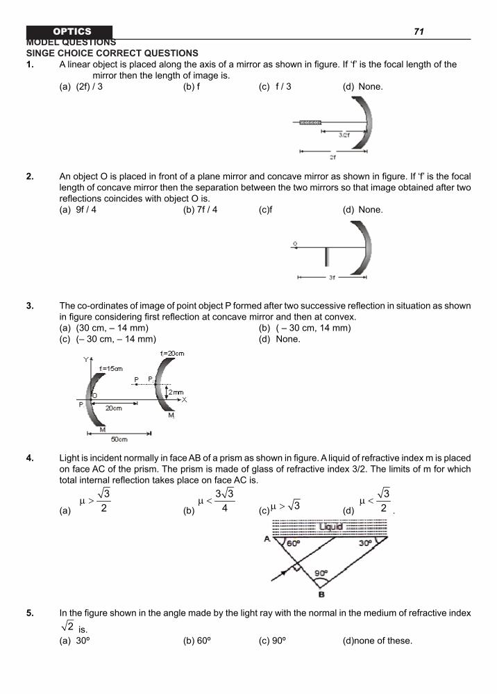
71 OPTICSMODEL QUESTIONSSINGE CHOICE CORRECT QUESTIONS1. A linear object is placed along the axis of a mirror as shown in figure. If ‘f’ is the focal length of the mirror then the length of image is. (a) (2f) / 3 (b) f (c) f / 3 (d) None.
2. An object O is placed in front of a plane mirror and concave mirror as shown in figure. If ‘f’ is the focal
length of concave mirror then the separation between the two mirrors so that image obtained after two reflections coincides with object O is.
(a) 9f / 4 (b) 7f / 4 (c)f (d) None.
3. The co-ordinates of image of point object P formed after two successive reflection in situation as shown in figure considering first reflection at concave mirror and then at convex.
(a) (30 cm, – 14 mm) (b) ( – 30 cm, 14 mm) (c) (– 30 cm, – 14 mm) (d) None.
4. Light is incident normally in face AB of a prism as shown in figure. A liquid of refractive index m is placed
on face AC of the prism. The prism is made of glass of refractive index 3/2. The limits of m for which total internal reflection takes place on face AC is.
(a)
32
µ > (b)
3 34
µ < (c) 3µ > (d)
32
µ <.
5. In the figure shown in the angle made by the light ray with the normal in the medium of refractive index
2 is. (a) 30º (b) 60º (c) 90º (d)none of these.

72 OPTICS
6. In the figure shown
sinisinr is equal to .
(a)
22
3 1
µµ µ (b)
3
1
µµ (c)
3 122
µ µµ (d) None of these.
7. A ray of light is incident normally on a prism of refractive index 1.5, as shown in figure. The prism is immersed in a liquid of refractive index ‘m’ . The largest value of the angle ACB, so that the ray is totally reflected at the face AC, is 60º. Then the value of m must be.
(a)
32 (b)
53 (c)
43 (d)
3 34 .
8. The x-z plane separates two media A and B with refractive indices m1 and m2 respectively. A ray of
light travels from A to B. Its directions in the two media are given by the unit vectors Aˆ ˆr ai bj= +
and
Bˆ ˆr i j= α + β
respectively where i and j are unit vectors in the x and y directions. Then.
(a) 1 2aµ = µ α (b) 1 2aµ α = µ
(c) 1 2bµ = µ β (d) 1 2bµ β = µ .
9. A ray of light is incident at angle i on a surface of a prism of small angle A and emerges normally form the opposite surface. If the refractive index of the material of the prism is m, the angle of incidence i is nearly equal to.
(a) A / m (b) A / 2m (c) mA (d) mA / 2.
MAY BE MORE THAN CORRECT CHOICE ANSWERS

73 OPTICS10. From a concave mirror of focal length f, image is 2 times larger. Then the object distance from the mirror
is.
(a)
f2 (b)
3f2
(c)
f4 (d)
4f3 .
11. For a mirror linear magnification m come out to be + 2. What conclusions can be drawn from this? (a) mirror is concave (b) mirror can be convex or concave but it can not be plane (c) object lies between pole and focus (d) object lies beyond focus.
12. Refractive index of an equilateral prism is 2 . (a) minimum deviation from this prism can be 30º (b) minimum deviation from this prism ca be 45º (c) at angle of incidence = 45º, deviation is minimum (d) at angle of incidence = 60º, deviation is minimum.
13. In refraction, ray of light passes undeviated, when. (a) medium on both sides is same (b) angle of incidence is 90º (c) angle of incidence is 0º (d) medium on other side is rarer.
14. A ray of light has speed v0 frequency f0 and wavelength in vacuum. When this ray of light enters in a medium of refractive index m, corresponding values are v, f and l Then.
(a)
0ff =µ (b)
0λλ =
µ
(c)
0vv =µ (d) 0f f= .
15. A convex lens made of glass (mg = 3/2) has focal length f in air. The image of an object placed infront of it is inverted real and magnified. Now the whole arrangement is immersed in water (mw = 4/3) without changing is distance between object and lens. Then.
(a) the new focal length will become 4f
(b) the new focal length will become
f4
(c) new image will be virtual and magnified (d) new image will be real inverted and smaller in size.
16. A converging lens is used to form an image on a screen. When the upper half of the lens is covered by an opaque screen.
(a) half of the image will disappear (b) complete image will be formed (c) intensity of the image will increase (d) intensity of the image will decrease.
17. The index of refraction for violet light in silica flint galss is 1.66 and thot for red light is 1.62 Let a visible light pass through a prism of apex angle with angle of incidence at , then
(a) deviation ofr violet is (b) deviation for red is (c) angular dispersion is (d) angular dispession is

74 OPTICS
COMPREHENSION@ Write-up–1
A point object O is placed at a distance of 0.3 m from a convex lens of focal length 0.2m. It is then cut into two halves each of which is displaced by 0.0005 m as shown in figure.
2 x 0.0005 mO
0.3 m
L1
L2
18. Image will be formed from the lens at a distance of (a) 30 cm (b) 40 cm (c) 50 cm (d) 60 cm.
19. Number of images found is (a) 3 (b) 2 (c) 1 (d) 4.
20. Separation between the images is (a) 0.2 cm (b) 0.4 cm (c) 0.3 cm (d) 0.6 cm.
@ Write-up–2
A convex lens of focal length 15 cm and a concave mirror of focal length 30 cm are kept with their optic axis PQ and RS parallel but separated in vertical direction by 0.6 cm as shown. The distance between the lens and the mirror is 30 cm. An upright object AB of height 1.2 cm is placed on the optic axis PQ of the lens at a distance of 20 cm form the lens.
A
BQS
P
R
30cm 20cm
21. If A B′ ′ is the image after refraction from the lens followed by reflection from the mirror, the position of A B′ ′ from the pole of the mirror is
(a) 15 cm in front of the mirror (b) 15 cm below the mirror (c) 20 cm in front of the mirror (c) 20 cm behind the mirror.
22. Overall magnification caused by lens and mirror (a) –3/2 (b) – 3 (c) 1/2 (d) 3/2.
23. Positions of A′ with respect to the optic axis is (a) 1.5 cm above RS (b) 1.5 cm below RS (c) 0.3 cm above RS (d) 0.3 cm below RS.

75 OPTICS
ASSERTION / REASONCodes. (a) Statement – 1 is True, Statement – 2 is True; Statement – 2 is a correct explanation for State-
ment – 1. (b) Statement – 1 is True, Statement – 2 is True; Statement – 2 is NOT a correct explanation for
Statement – 1. (c) Statement – 1 is True, Statement – 2 is False. (d) Statement – 1 is False, Statement – 2 is True.
24. STATEMENT – 1 Shaving, we prefer to use a concave mirror. STATEMENT – 2 A concave mirror gives an enlarged image when used in this manner.
25. STATEMENT – 1 If a plane glass slab is placed on the letters of different colours all the letters appear to be raised up
to the different height. STATEMENT – 2 Different colours have different wavelength.
26. STATEMENT – 1 Higher is the refractive index of a medium or denser the medium, lesser is the velocity of light in that
medium. STATEMENT – 2 Refractive index is inversely proportional to velocity of light in the medium.
27. STATEMENT – 1 The blue colour of sky is on account of scattering of sunlight. STATEMENT – 2 The intensity of scattered light varies inversely as the fourth power of wavelength of light.
28. STATEMENT – 1 An air bubble in a jar of water shines brightly due to phenomenon of reflection. STATEMENT – 2 Refraction of light is the phenomenon of change in the path of light, when it goes from one medium
to another.
MATRIX MATCH
Each question contains statements given in two column which have to be matched. Statements (a, b, c, d) in Column A have to be matched with statements (p, q, r, s) in Column B. The answers to these questions have to be appropriately bubbled as illustrated in the following example.
29. A plane mirror is tied to the free end of an ideal spring. The other end of the spring is attached to a wall. The spring with mirror is held vertically to the floor, can slide along it smoothly. When the spring is at its natural length, the mirror is found to be moving at a speed of V with respect to ground frame. An object is moving towards the mirror with speed 2V with respect to ground frame. Then, Match the following .

76 OPTICS
2V
VMirror
Wall
30. Choose the correct matching in Column B corresponding to statements in Column A.
SSINGE CHOICE CORRECT QUESTIONS
31. A ray of light strikes a plane mirror at an angle of incidence 45º as shown in the figure. After reflection, the ray passes through a prism of refractive index 1.50, whose apex angle is 4º. The angle through which the mirror should be rotated if the total deviation of the ray is to be 90º is.
(a) 1º clockwise (b) 1º anticlockwise (c) 2º clockwise (d) 2º anticlockwise.
32. Two parallel light rays pass through an isosceles prism of refractive index 32 as shown in the figure. The angle between the two emergent rays
is. (a) 45º (b) 30º (c) 15º (d) 60º.
33. A thin prism has different medium on its either side. A light ray is incident almost normally on the first face. What is the angle of deviation if all the angles are very small.
(a)
1
2 2
I 1 A 1 µ µ
− − − µ µ (b)
1
2 2
I 1 A 1 µ µ
− + − µ µ
(c)
1
2 2
I 1 A 1 µ µ
+ − − µ µ (d) None.
34. A plane mirror is placed at the bottom of a tank containing a liquid of refractive index m. P is a small object a height h above the mirror. An observer O – vertically above P, outside the liquid – submerged sees P and its image in the mirror. The apparent distance between these two will be

77 OPTICS
(a) 2mh (b)
2hµ
(c)
2h1µ − (d)
1h 1 + µ .
35. P is a point on the axis of a concave, mirror. The image of P, formed by the mirror, coincides with P. A rectangular glass slab of thickness t and refractive index m is now introduced between P and the mirror. For the image of P to coincide with P again, the mirror must be moved.
(a) towards P by (m – 1)t (b) away from P by (m – 1)t (c) towards P by t(1 – 1/m) (d) away from P by (1 – 1/m)t.
36. A ray of light travels from an optically denser to rarer medium. The critical angle for the two media is c. The maximum possible deviation of the ray will be
(a) p – c (b) p - 2c (c) 2c (d) p/2 + c.
37. A transparent sphere of radius R and refractive index m is kept in air. At what distance from the surface of the sphere should a point object be placed so as to form a real image at the same distance from the sphere?
(a) R/m (b) mR (c) (d) .
38. An air bubble is inside water. The refractive index of water is 4/3. At what distance from the air bubble should a point object be placed so as to form a real image at the same distance from the bubble?
(a) 2R (b) 3R (c) 4R (d) The air bubble cannot form a real image.
39. A converging lens forms a real image I on its optic axis. A rectangular glass slab of refractive index m and thickness t is introduced between the lens and I. I will move
(a) away from the lens by t(m – 1) (b) towards the lens by t(m – 1) (c) away from the lens by t(1 – 1/m ) (d) towards the lens by t(1 – 1/m).
40. A diminished image of an object is to be obtained on a screen 1.0 m from it. This can be achieved by appropriate placing .
(a) a concave mirror of suitable focal length (b) a convex mirror of suitable focal length (c) a convex lens of focal length less than 0.25 m (d) a convex lens of suitable focal length
MAY BE MORE THAN CORRECT CHOICE ANSWERS
41. A ray of light traveling in a transparent medium falls on a surface separating the medium from air, at an angle of incidence of 45º. The ray undergoes total internal reflection. If n is the refractive index of the medium with respect to air, select the possible values of n from the following
(a) 1.3 (b) 1.4 (c) 1.5 (d) 1.6
42. A ray of light traveling in a transparent medium falls on a surface separating the medium from air at an angle of incidence 45º. The ray undergoes total internal reflection. If n is the refractive index of the medium with respect to air, select the possible value (s) of n from the following.
(a) 1.3 (b) 1.4 (c) 1.5 (d) 1.6.
43. Light incident on a surface separating two media is partly reflected and partly refracted as shown in

78 OPTICS
the figure given ahead.
(a) ( )2
1/22 21 2
nsinin n
=+
(b)
1
2
ntanin
=
(c) csini cot i= (d) csini sec i= .44. A solid, transparent sphere has a small, opaque dot at its centre. When observed from outside, the
apparent position of the dot will be (a) closer to the eye than its actual position (b) farther away from the eye than its actual position (c) the same as its actual position (d) independent of the refractive index of the sphere.
45. A water-filled hollow glass prism is mounted on a spectrometer and a parallel beam of monochromatic light is incident on one of the refracting faces from the side of the base. The angle of prism is 60º. On refraction through the prism.
(a) the emergent beam gets deviated away from the base (b) there is a position of the prism for the minimum deviation (c) the refractive index of water with respect to air can be computed (d) the refractive index of water with respect to glass alone can be computed.
46. A thin concavo-convex lens has to surfaces of radii of curvature R and 2R. The material of the lens has a refractive index . When kept in air, the focal length of the lens
(a) will depend on the direction from which light is incident on it (b) will be the same, irrespective of the direction from which light is incident on it
(c) will be equal to
R1µ −
(d) will be equal to
2R1µ − .
47. If a convergent beam of light passes through a diverging lens, the result (a) may be a convergent beam (b) may be a divergent beam (c) may be a parallel beam (d) must be a parallel beam
48. Which of the following form virtual and erect images for all positions of the real object? (a) Convex lens (b) Concave lens (c) Convex mirror (d) Concave mirror.
49. In the displacement method a convex lens is placed in between an object and a screen. If the magnifications in the two positions are m1 and m2, the focal length of the lens is. (x is the diff. In position of lens)
(a) x/(m1 + m2) (b) x/(m1 – m2) (c) [x/(m1 + m2)
2] (d) [x/(m1 – m2)2].

79 OPTICS
COMPREHENSION@ Write-up–1
The following figure shows a simple version of a zoom. The converging lens has a focal length f1 and the diverging lens has focal length f2 = – |f2|. The two lenses are separated by a variable distance d that is always less than f1, also the magnitude of the focal length of the diverging lens satisfies the inequality |f2| > (f1 – d). If the rays that emerge from the diverging lens and reach the final image point are extended backward to the left of the diverging lens, they will eventually expand to the original radius r0 at the same point Q. To determine the effective focal length of the combination lens consider a bundle of parallel rays of radius r0 entering the converging lens.
r0 r'0
f1f =-|f |1 2
Q
df
s'2
I'
50. At the point where ray enters the diverging lens, the radius of the ray bundle decreases to.
(a)
10 0
1
f dr rf
−′ = (b)
10 0
1
f dr rf
− ′=
(c)
1 20 0
1
f fr rf
−′ = (d) 0 0r r′ = .
51. To the right of the diverging lens the final image I′ is formed at a distance 2s′ given by.
(a)
( )1 2
2 1
f f df f d
−− + (b)
( )1 2
2 1
f d ff d f
−+ −
(c)
1 2
1 2
f f df f− +
− (d)
( )1 2
1 2
d f ff f d
−− −
52. The effective focal length is given by.
(a)
1 1
1 1
f ff f d− + (b)
1 2
1 2
f ff f d− −
(c)
1
2 1
ff f d− + (d)
2
1 2
ff f d+ + .
@ Write-up–2Mirror
0.9m 0.8m
A thin equiconvex lens of glass of refractive index. m = 3/2 and of

80 OPTICSfocal length 0.3 m in air is sealed into an opening at one end of a tank filled with water (m = 4/3). On the opposite side of the lens, a mirror is placed inside the tank on the tank wall perpendicular to the lens axis, as shown in figure. The separation between the lens and the mirror is 0.8 m. A small object is placed outside the tank in front of the lens at a distance of 0.9 m from the lens along its axis.
53. Radius of curvature of any of the curved surface of equiconvex lens is. (a) 0.3 m (b) 0.4 m (c) 0.5 m (d) 0.6 m.
54. After refraction at glass-water interface, the position of real image formed by the mirror is. (a) at a distance of 0.4 m from the lens (b) at a distance of 0.3 m from the lens (c) at a distance of 0.2 m from the lens (d) at a distance of 0.1 m from the lens.
55. After final refraction at glass-air interface, where the image appears to be formed? (a) 0.6 m from the lens on the side of the mirror (b) 0.7 m from the lens on the side of the mirror (c) 0.8 m from the lens on the side of the mirror (d) 0.9 m from the lens on the side of the mirror.
ASSERTION / REASONCodes. (a) Statement – 1 is True, Statement – 2 is True; Statement – 2 is a correct explanation for State-
ment – 1. (b) Statement – 1 is True, Statement – 2 is True; Statement – 2 is NOT a correct explanation for
Statement – 1. (c) Statement – 1 is True, Statement – 2 is False. (d) Statement – 1 is False, Statement – 2 is True.
56. STATEMENT – 1 Just before setting, the sun may appear to be elliptical. This happens due to refraction. STATEMENT – 2 Refraction of light rays through the atmosphere may cause different magnification in mutually
perpendicular directions.
57. STATEMENT – 1 Critical angle of light passing from glass to air is minimum for violet colour. STATEMENT – 2 The wavelength of blue light is greater than the light of other colours.
58. STATEMENT – 1 The sun looks bigger in size at sunrise and sunset than during day. STATEMENT – 2 The phenomenon of diffraction bends light rays.
59. STATEMENT – 1 The images formed by total internal reflections are much brighter than those formed by mirrors or lenses. STATEMENT – 2 There is no loss of intensity in total internal reflection.
60. STATEMENT – 1 A convex lens of glass (m = 1.5) behaves as a diverging lens when immersed in carbon disulphide of
higher refractive index (m = 1.65). STATEMENT – 2

81 OPTICS A diverging lens is thinner in the middle and thicker at the edges.
MATRIX MATCH
Each question contains statements given in two column which have to be matched. Statements (a, b, c, d) in Column A have to be matched with statements (p, q, r, s) in Column B. The answers to these questions have to be appropriately bubbled as illustrated in the following example.
61. A cocave mirror of focal length f with pole at origin is as shown. A point object ‘O’ is located in XY plane
as given in columnA. The column B gives the position of point image so formed. Here are x&y
co-ordinates of point object, simillarly are x & y co-ordinates of point image respectively.
Column – A Column – B
(a) (p)
(b) (q)
(c) (r)
(d) (s) 62. The greatest thickness of a plan convex lens when viewed normally through the plane surface appears
to be 0.03m and when viewed normally thorugh the curved surface it appears to be 0.036m. The actual thickness is 0.045m.Then, match the following
Column – A Column – B (a) refractive index of the material of lens (p) 1.5 (b) radius of curvature of the lens (q) 9 cm (c) focal length, if its plane surface is silvered (r) -9 cm (d) focal length, if its curved surface is silvered (s) -3 cm a) p b) q c) r d) s
LEVEL-IIIMODEL QUESTIONS
SINGE CHOICE CORRECT QUESTIONS
1. (b) 2. (a)3. (a) 4. (b)5. (a) 6. (b)7. (d) 8. (a)9. (c)
MAY BE MORE THAN CORRECT CHOICE ANSWERS

82 OPTICS
10. (a, b) 11. (a, c)12. (a, c) 13. (a, c)14. (b, c, d) 15. (a, c)16. (b, d) 17. (b, c)
COMPREHENSION@ Write-up–1
18. (d) 19. (b) 20. (c)
@ Write-up–2
21. (a) 22. (a) 23. (b)
ASSERTION / REASON
24. (a) 25. (a)
26. (a) 27. (a) 28. (d)
MATRIX MATCH29. (a – r) (b – p) (c – r) (d – r)
30. (a – r) (b – p, r) (c – q, r) (d – p, r, s)
PRACTICAL QUESTIONS
SINGE CHOICE CORRECT QUESTIONS
31. (b) 32. (b)33. (a) 34. (b)35. (d) 36. (b)37. (c) 38. (d)39. (c) 40. (c)
MAY BE MORE THAN CORRECT CHOICE ANSWERS
41. (c, d) 42. (c, d)43. (a, c) 44. (c, d)45. (b, c) 46. (b, d)47. (a, b, c) 48. (b, c) 49. (b)
COMPREHENSION
@ Write-up–1
50. (a) 51. (b) 52. (a)

83 OPTICS
@ Write-up–2
53. (a) 54. (a) 55. (d)
ASSERTION / REASON
56. (a) 57. (c)58. (b) 59. (a)60. (b)
MATRIX MATCH
61. (a – p,r) (b – q,s) (c – s) (d – r)62. (a – p) (b – q) (c – r) (d – s)
LEVEL – III
MODEL QUESTIONS
SINGE CHOICE CORRECT QUESTIONS
1. The image of object at 2f will be formed at 2f. So the object and image will coincide at 2f
Image of
3f2
1 1 1v u f
− =
1 1 13fv f2
− =−
1 1 2 1v f 3f 3f
= − =
V = 3f ∴ Length of image = 3f – 2f = f.
2.
1 1 1v f 3f
= −− −
3fv2
= −
Reqd. dist =
3f 1 3f 9f3f2 2 2 4
+ − = .
3.
1 1 1v 20 15
= − +− −
⇒ v = – 60 cm
1
60m 320
− = − = − −

84 OPTICS
final
1 1 1v 10 20
= − +
⇒ finalv = – 20 cm; 2
20m 210− = − =
4. w g
1 1sin60 3 / 2
µ > =
g
w
23
µ>
µ ⇒
3 / 2 23
>µ
⇒
3 34
µ <.
5. (1) ( ) ( )1 2 sin
2
= θ
⇒ q = 30º6. m1 sin I = m3 sin r
7. ( )1.5 sin60º sin90º= µ
⇒
3 34
µ =.
8. am1 = am2
AB
jbia +
ji β+α
9. i – A = (m – 1)A ⇒ I = mA.
MAY BE MORE THAN CORRECT CHOICE ANSWERS
10. If image is virtual. Then suppose u = - x, then v = + 2x From the mirror formula
1 1 1v u f
+ = or
1 1 12x x f
− =−
or
fx2
=
if image is real. Then suppose u = - y then v = - 2y Again applying the mirror formula
1 1 12y y f
− = −−
or
3 12y f
=

85 OPTICS
∴
3y f2
=.
11. M = + 2 means image is virtual, erect and magnified. Virtual magnified image can be formed only by a concave mirror and that too when object lies between pole and focus.
12. From
mAsin2Asin2
+ δ µ =
we can see that m 30ºδ = for 2µ = and A =60º Further, at minimum deviation,
1 2
Ar r 30º2
= = =
∴ 1 1sini sinr= µ
( )2 sin30º=
12
=
∴ 1i 45º= .13. Ray passes undeviated when m1 = m2 or ray is normal or angle of incidence is 0º.14. In passing from vacuum to a medium, frequency remain unchanged while speed and wavelength
decreases a time.
15. air 1 2
1 3 1 11f 2 R R
= − −
water 1 2
1 3 / 2 1 11f 4 / 3 R R
= − −
From these two equations we get ,
water airf 4f 4f= =
In air object was inverted, real and magnified. Therefore, object was lying between f and 2f. Now the focal length has changed two 4f. Therefore, the object now lies between pole and focus. Hence, the new image will be virtual and magnified.
16. When upper half of the lens is covered, image is formed by the rays coming from lower half of the lens. Or image will be formed by less number of rays. Therefore, intensity of image will decrease. But complete image will be formed.
17.

86 OPTICS
angular dispersion COMPREHENSION@ Write-up–1
18.
1 1 1v 0.2 0.3
= +−
⇒ v = 60 cm19. Two
20.
v 60m 2v 30
= = = −−
∴ depuration = 0.3 cm
@ Write-up–2
21.
1 1 1v 15 20
= +−
⇒ v = 60 cm
final
1 1 1v 30 30
= −−
⇒ finalv 15= − cm. 180. 22. m = m1 ´ m2
= ( – 3)
12
×
32
= −.
23. 1.5 cm below RS24. When an object between the focus and the pole of a concave mirror, the image is erect and enlarged.
25. , the images should appear to be raised by different amounts.

87 OPTICS
26. Refractive index .27. The wavelength of blue light is smaller than that of red light.28. The phenomenon is due to total internal reflection.
MATRIX MATCH
29. velocity of image w.r.t. ground = 2v velocity of image w.r.t. mirror = v velocity of image w.r.t. object = 2v 30. Frequency of the wave remains invariant. The speed of the wave depends on the medium; and there
is a phase change of 180º on reflection at a denser medium. S
PRACTICAL QUESTIONS
SINGE CHOICE CORRECT QUESTIONS
31. ( )1 Aδ = µ − = 2º ∴ mirror should be rotated by 1º anticlock vise.
32.
3 1 12 2
=
60ºθ = ∴ regd. Angle = 30º
33. ( )i e Aδ = + − … (i)
1 1i rµ = µ
⇒
11r iµ
=µ … (ii)
2 1r A r= −
⇒ ( )1 2A r eµ − = µ
⇒ ( )1
2
e A rµ= −
µ
∴
1
2
i A i Aµ µδ = + − − µ µ
1
2 2
i 1 A 1 µ µ
− − − µ µ .
34. 1
xv = −µ

88 OPTICS
1
x 2hv +′ = −µ
∴
2hdist =µ .
35. By moving the mirror away by
11 t − µ , the effective situation remains unchanged.
36.
π-2C
C
37. v
1 1Ltv R→∞
µ µ −− =
µ
⇒
Rv1
= −µ −
38. Virtual image will be formed.
39. Image will appear shifted by
1t 1 − µ
40. Image can be formed on the screen if it is real. Real image of reduced size scan be formed by a concave mirror or a convex lens as shown in figure.
A diminished real image is formed by a convex lens when the object is placed beyond 2f and the image of such object is formed beyond 2f on other side.
Thus, d > (2f + 2f) or 4f < 0.1 m or f < 0.25 mMAY BE MORE THAN CORRECT CHOICE ANSWERS
41. For T.I.R. 450 > C
⇒
1sinC2
<
⇒ 1.414µ > .42. For total internal reflection to take place. Angle of incidence, i > critical angle, qc or sin i > sin qc or sin 45º > 1/n
or
1 1n2
>
or n 2> Or n > 1.414 Therefore, possible values of n can be 1.5 or 1.6 in the given options.

89 OPTICS
43. ( )1 2n sini n sin 90 i= −
2
1
n 1tanin sinC
= =
22 21 2
nsinin n
=+ .
44. The rays are radial.45. This is equivalent to a water prism. 46. For thin lens, it doesn’t matter which side faces light.
Also, ( )1 1 11
f R 2R = µ − − + +
47. Any of (a), (b) or (c) is possible depending upon the divergence caused. 48. Concave lens and convex mirror form virtual image of a real object.
49. 1
D xmD x
+=
− , 2
D xmD x
−=
+ and
2 2D xf4D−
=
( )2 2
1 2
x D xx fm m 4Dx
−= =
− .
COMPREHENSION@Write-up–1
50. From similar s∆
10 1
0 1
r f dr f
−=
.51. For diverging lens
1 2 2u (f d), f | f |= + − = −
1 2
2 1
(f d) | f |v| f | d f
−∴ =
+ − .
52. eff 1 2 1 2
1 1 1 df f f f f
= + −.
@ Write-up–2
53. to 55. From lens Maker’s formula,
1 2
1 1 1( 1)f R R
= µ − −
we have
1 3 1 110.3 2 R R
= − − − (here, R1 = R and R2 = – R)
R 0.3∴ =
Now applying 2 1 2 1
u Rµ µ µ − µ
= =ν at air glass surface, we get

90 OPTICS
1
3 3 112 2(0.9) 0.3
−− =
ν −
1 2.7m∴ ν = . i.e., first image I1 will be formed at 2.7 m from the lens. This will act as the virtual object for glass water
surface.
Therefore, applying 2 1 2 1
u Rµ µ µ − µ
− =ν at glass water surface we have
2
4 4 333 3 22
2.7 0.3
−= =
ν −
i.e., second image I2 is formed at 1.2 m from the lens or 0.4 m from the plane mirror. This will act as a virtual object for mirror. Therefore, third real image I3 will be formed at a distance of 0.4 m in front of the mirror after reflection from it. Now this image will work as a real object for water–glass interface. Hence, applying
2 1 2 1
u Rµ µ µ − µ
− =ν
we get 4
4 3 433 2 32
(0.8 0.4) 0.3
−− =
ν − −
4 0.54 m∴ ν = −
i.e., fourth image is formed to the right of the lens at a distance of 0.54 m from it. Now finally applying the same formula for glass–air surface,
5
3 311 2 20.54 0.3
−− =
ν − −
5 0.9 m∴ ν = −
i.e., position of final image is 0.9 m relative to the lens (rightwards) or the image is formed 0.1 m behind the mirror.
ASSERTION / REASON
56. The refractive index of the atmosphere varies with height.
57. Sun .58. The sun looks bigger at sunrise and sunset due to refraction. 59. Since no light undergoes refractino (in TIR) the reflected light is of maximum intensity.
60. .MATRIX MATCH
61. For a For b For c

91 OPTICS
62.
if plane surface is silvered
F=-9cm If curved surface is silvered
INTEGER ANSWER TYPE QUESTIONS
MODEL QUESTIONS
1. Three mirrors lying along x-y, y-z and z-x places are joined at the origin. An object is placed in the first octant. How many images are formed ?
2. The inside surface of a cylindrecal shell of diameter 1 cm and length 8cm is silvered . A thin parallel beam of light, containing the axis of the cylinder in its plane of motion, enters it its silvery surface close to one end. Given the angle of incidence as 530, find the number of reflections that the beam undergoes before at the other end of the tube.
3. An object stands on a plane mirror Parallel light rays fall on it forming the shadow of the object by reflection on a screen positioned vertically, what is the maximum possible number of shadows that can be spotted on the screen ?

92 OPTICS
4. Light falls on a prism of angle . If the minimum value of refractive index of the prism-
material, so that light entering one face may not exit through the other is , then k = ?
PRACTICE QUESTIONS
5. Two plane mirrors with their shiny sides facing meet at an angle of . A pencil of parallel light rays moving parallel to one of the mirrors parallel the line of maximum slope of the mirror, strikes the other mirror. After how many reflections does it leave the mirror system to returns on its path ?
6. A point object is placed on the principal axis of a concave mirror of focal length 15cm at a distance
of 190cm from it. A converging lense of focal length 40cm, located between the object and the mirror is moved around to discover any positions such that the final image of the
point object coincides with the object itself. How many different positions of the lens can be found. 7. A glass biconvex lens of radii of curvature 50cm and 100 cm, with its latter face silvered is placed
in air. The refractive index of glass is 1.5. What is the power of the optical system in diopter ? 8. A rod of length 10 cm lies along the principal axis of a concave mirror of focal length 10 cm in such a
way that the end closer to the pole is 20 cm away from it. find the length of image in cm.
9. A glass prism of angle 60º and index of refraction 1.5 is immersed in a liquid of refractive index 1.33. If the angle of minimum deviation inside the liquid is not more than δ then find δ (in degree).
KEY
1. 7 2. 6 3. 2 4. 4 5. 3 6. 3 7. 5 8. 5 9. 9.
HINTS AND SOLUTIONS
1. 7 images are formed at the remaining 7 corners of the cuvoid formed by the object and image ( formed by these reflections ) serving as its long digonal.
2.
3.

93 OPTICS
4.
now, required
5. Reflecting off the first mirror the ray strikes the second one orthogonally6. two positions of the lens correspond to the situation when the image in the lens is made at the pole
of the mirror . one position of lens corresponds to the situation when the image in the lens is formed at the center of the curvature of the mirror.
7. p = 5D
8.
Thus the image of A is formed at 15 cm from the pole. the length of the image is, therefore, 5.0 cm.
9.
m
g
Asin2Asin2
δ +
µ =
m m60 60sin sin1.5 2 260 11.33 sin2 2
+ δ + δ
= =
m 8º 40 ' 9ºδ = <
SUBJECTIVE QUESTIONS
1. Find the height to the shortest plane mirror fixed vertically on the wall of a room in which a man stands at the centre of the room can see the full images of the wall behind him.
2. If a luminous point is moving at a speed 0V towards a spherical mirror, along its axis, show that the speed at which the image of this object is moving will be given by.
2
i 0fV V
u f = − −
3. A thin rod of length (f / 3) is placed along the principal axis of a concave mirror of focal length f such that its image which is real and elongated, just touches the rod. What is the magnification?

94 OPTICS4. A man standing on the edge of a swimming pool looks at a stone lying on the bottom. The depth of
the swimming pool is equal to h . At what distance from the surface of water is the image of the stone formed if the line of vision makes an angle θ with the normal to the surface?
A B
C5. A right prism is made by selecting a proper material and the angles
A and B(B A)<< as shown in figure. It is desired that a ray of light incident on the face AB emerges parallel to the incident direction after two internal reflections.
(i) What should be the minimum refractive index n for this to be possible?
(ii) For n 5 / 3= is it possible to achieve this with the angle B equal to 30 degree?
6. A ray of light is incident at an angle of 60º on one face of a prism which has an angle of refraction of 30º If the angle of deviation of the ray after it traverses the prism is 30º, show that the emergent ray is perpendicular to the face through which it emerges and calculate the refractive index of the material of the prism.
7. A rectangular block of glass is placed on a printed page lying on a horizontal surface. Find the minimum value of the refractive index of glass for which the letters on the page are not visible from any of vertical faces of the block.
8. Light is incident at an angle α on one of the flat surfaces of a transparent cylindrical rod of refractive index n . Determine the least value of n so that the light entering the rod does not emerge from the curved surface of the rod irrespective of the value of α .
9. A rod made of glass ( 1.5)µ = and of square cross-section is bent into the shape shown in figure. A parallel beam of light falls perpendicularly on the plane flat surface A . Referring to the diagram, d is the width of a side and R the radius of inner semi-circle. Find the maximum value of ratio (d / R) so that all light entering the glass through surface A emerge from the glass through B .
10. A glass prism of angle 72º and index of refraction 1.66 is immersed in a liquid of refractive index 1.33. Find the angle of minimum deviation for a parallel beam in light passing through the prism. Take sin 36º = 0.6, sin 48º = 0.75.
11. The refractive index of the material of a prism of refracting angle 45º is 2 for a certain monochromatic ray. What would be the minimum angle of incidence of this ray on the prism so that no total internal reflection takes place as the ray comes out the of prism? (Take sin 15º = 0.26).
12. A cylindrical glass rod of radius 0.100m and refractive index 3 lies on a horizontal plane mirror. A horizontal ray of light moving perpendicular to the axis of the rod is incident on it. At what height from
the mirror should the ray be incident so that it leaves the rod at a height of 0.100m above the plane mirror? At what distance a second similar rod parallel to the first be placed on the mirror such that the emergent ray from the second rod is in line with the incident ray on the first rod?
13. If a mark, of size 0.2cm made on the surface of a glass sphere of diameter 10cm and 1.5µ = is viewed through the diametrically opposite point, where will the image be seen and of what size?
14. Consider a co-axial system of two thin convex lenses of focal length f each separated by a distance

95 OPTICS
d . Draw ray diagrams for image formation corresponding to an object at infinity placed on the principal axis in the following cases (a) d f< (b) d f= (c) f d 2f< < (d) d 2f= and d 2f> . Indicate the nature of the combination (concave, convex or plane) in each case.
15. A convex lens A of focal length 20cm and a concave lens B of focal length 5cm are kept along the same axis with a distance d between them. What is the value of d if a parallel beam of light incident on A leaves B as a parallel beam?
SUBJECTIVE QUESTIONSKEY
1. 3 EF.
2.
2
i 0fV V
u f = − −
3. - 3/2
4.
2 3
2 2 3/2
hcosh( sin )
µ θ′ =µ − θ
5. (i) 1.414 (ii) no.6. 1.732
7. 1.4µ =
8. value of n is 2
9. max
d 0.5R
=
10. m 24ºδ = (approx)
11. The minimum value of 1i is 31º12. 3.15 cm13. 0.6 cm14. (a) d < f (b) d =f (c) f < d < 2f (d) d = 2f (e) d < 2f.15. d = 15 cm.
SUBJECTIVE QUESTIONS
HINTS AND SOLUTIONS
1. In figure MN is the man with E as the position of the eyes. He is standing at N such that KN NB=
. AB is the wall. For full image to be seen, the rays starting from A strike the wall LK at S and similarly the rays from B strike at G. This gives the minimum size of the mirror for full wall to be seen. In the mirror SG , the rays appear to come from A B′ ′
Now ESG∆ and EA B′ ′ are similar
∴
SG EFA B EH
=′ ′

96 OPTICS
where EH is perpendicular drawn to A B′ ′
or,
EF 1SG AB ABEH 3
= × =.
EH FH EF= + KB EF= + 2KN EF= +
3EF= . [ A B AB]′ ′ = .2. In case of spherical mirrors
1 1 1v u f
+ = … (i)
or, 2 2
1 dv 1 du 0dt dtv u
− − = [as f is constant]
or,
2
i 0vV Vu
= i 0
dv duas V and Vdt dt
= = But from equation (i)
1 1 1v f u
= − i.e.,
ufv(u f )
=−
So,
2
i 0fV V
u f = − − .
which is the desired result. 3. As the image is real and enlarged, the object must be between C and F . Also as the image of one
end coincides with the end itself, i.e., A Av u= , the rays return to A after reflection on the mirror; this happens only if the rays are incident normally on the mirror i.e. A is located at the centre of curvature, C of the concave mirror.
Now as the length of the rod is (f / 3) , its other end B will be at a distance [2f (f / 3)] (5 / 3)f− = from P . So if the distance of image of end B fromP is Bv ,
B
1 1 1v (5 / 3)f f
+ =− −
i.e., B
5v f2
= −
So the size of the image
B A
5 1| v | | v | f 2f f2 2
− = − =
and so
B A
B A
(v v ) (1/ 2)f 3m(u u ) (1/ 3)f 2
−= − = − = −
− .

97 OPTICS
4. The situation is shown in figure.
θ
α
A
h'
O
BB'
θ
h
α
O'
For figure, AB h tan= α … (i) Similarly, AB h tan′ ′= θ … (ii) Now h tan h tan′α − θ = constant Differentiating both sides, we get
2 2dhsec h sec 0
dα ′α − θ =θ
or, 2 2
h d hdcos cos
′α = θα θ
or,
2
2
hcos dhdcos
θ α ′ = θθ … (iii)
We know that,
sinsin
θµ =
α
or, sin sinθ = µ α … (iv)Differentiating both sides, we get
dcos cosdα θ = µ α θ
or,
d cosd cosα θ = θ µ α … (v)
Substituting the value of (d / d )α θ from equation (v) in equation (iii), we get
2
2 3
hcos cos hcoshcoscos cos
3θ θ θ′ = × =µ αα µ α … (vi)
from equation (iv),
sinsin θα =
µ
∴
2
2
sincos 1 θ
α = − µ
or,
3/22 2 2 3/23
2 3
sin ( sin )cos 1 θ µ − θ
α = − = µ µ
Substituting the value of 3cos α in equation (vi), we have
2 3
2 2 3/2
hcosh( sin )
µ θ′ =µ − θ .
5. (i) As shown in figure, the ray MN falls normally on face AB and hence passes undeviated
along NO . The angle of incidence 1i for face AC is equal to A . The direction of reflected ray
is 2OP i⋅ is the angle of incidence for this ray on face BC . It is obvious from figure that 2i B=

98 OPTICS.
From the geometry of figure A B 90º∠ + ∠ = . As B A<< , the ray gets totally reflected
only if 2i C> or B C> . Here C be the critical angle of the prism and air interface.
We know that
1nsinC
=
min
1nsinB
=
When A B= , min
1n 2 1.414sin45º
= = =
(ii) When B 30º= ; then
min
1 1n 2sinB sin30º
= = =
Therefore minn 5 / 3 n= < and B 30º= , the condition can not be achieved. 6. The situation is shown in the figure.
For a prism, let
1i = angle of incident
2i = angle of emergence A = angle of prism δ = angle of deviation,
then, 1 2i i A+ = + δ … (i)
and, 1 2r r A+ = … (ii)For equation (i),
2 1i A i 30º 30º 60º 0= + δ − = + − = ( A 30º, i 60º= = and 30º )δ =
Thus the emergent ray is normal to the other face.
When 2i 0= , 2r 0=
∴ From equation (ii), 1r A 30º= =
From Snell’s law
1
1
sini sin60º 3 / 2 3sinr sin30º 1/ 2
µ = = = = 1.732= .
Here emergent ray is normal to the other face, AC .7. Let XNY be the printed page lying on a horizontal surface as shown in figure. ACBD is a rectangular
block of glass placed on the page. An air film is enclosed between the glass block and the printed page as shown by shaded portion in the figure. Let a ray PQ falls on the block at grazing incidence and being refracted along QS . Now GQS∠ represents the critical angle for the glass and let this value
be Cθ . When the angle of incidence is greater than Cθ total internal reflection will occur.
Now, C CGSQ 90º∠ = −θ = θ
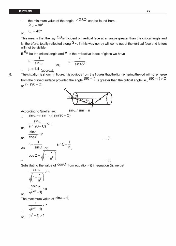
99 OPTICS
∴ the minimum value of the angle, GSQ∠ can be found from .
C2 90ºθ =
or, C 45ºθ =
This means that the ray QS is incident on vertical face at an angle greater than the critical angle and is, therefore, totally reflected along SL . In this way no ray will come out of the vertical face and letters will not be visible.
If Cθ be the critical angle and µ is the refractive index of glass we have
C
1sin
µ =θ or,
1sin45º
µ =
∴ 1.4µ = (approx). 8. The situation is shown in figure. It is obvious from the figures that the light entering the rod will not emerge
from the curved surface provided the angle (90 r)− is greater than the critical angle i.e., (90 r) C− >
or r (90 C)< − .
According to Snell’s law, sin / sinr nα =
∴ sin nsinr nsin(90 C)α = < −
or,
sin nsin(90 C)
α<
−
or,
sin ncosC
α<
… (i)
As
1nsinC
= or,
1sinCn
=,
∴ 2
1cosC 1n
= − … (ii)
Substituting the value of cosC from equation (ii) in equation (i), we get
2
sin n11n
α<
−
or, 2
nsin n(n 1)
α<
−
The maximum value of sin 1α = .
∴ 2
1 1(n 1)
<−
or, 2(n 1) 1− >

100 OPTICS
or, 2n 2>
n 2>
So the least value of n is 2 .9. In order that all the ray entering at A emerge from B , the angle of incidence i for a ray (say PQ
shown in figure), should be equal to or greater than critical angle Cθ for air glass interface. So,
1C
1i sin− ≥ θ = µ
or,
1sini ≥µ
From figure,
PO RsiniOQ (R d)
= =+
∴
R 1(R d) 1.5
≥+ or, 1.5R (R d)≥ +
or, 0.5R d≥ or, d / R 0.5≤
∴ max
d 0.5R
= .
10. Here a g 1.66µ = and a w 1.33µ =
∴ w
a gw g
a
1.661.33
µµ = =
µ
We know that
msin(A ) / 2 1.66
sin A / 2 1.33+ δ
µ = = = 1.25 (approx).
or,
m72ºsin2 1.25
sin36º
+δ =
m72ºsin 1.25sin36º 0.752+δ = =
(approx)
or, m72º 48º
2+δ
=
∴ m 24ºδ = (approx).11. Since the ray does not suffer total internal reflection, therefore,
1 2r r C< ≤ … (i) We
know that
1 1sinC 0.52
= = =µ
∴ C 30º=
Also 1 2r r A+ =
or, 1 2r 45º r= −
or, 1r 45º 30º 15º≥ − = [from equation (i)]

101 OPTICS
Also
1
1
sini 2sinr
= or, 1 1sini 2 sinr= ×
Since 1r 15º≥
∴ 1sini 2 sin15º≥ ×
or, 1sini 0.52≥
1i 31º≥
Therefore the minimum value of 1i is 31º.
12. The given situation is shown in figure. If the ray is incident at a height h (in cm), from Snell’s law at B
, sini sinr= µ . But from the geometry of the figure, i 2r= so
sini 3 sin(i / 2)=
or, cos(i / 2) ( 3 / 2)=
i.e., i 60º=
Now from figure in BHO∆ ,
1
BH h RsiniBO R
−= =
or,
h 10 3sin60º10 2−
= =
or, h 10 5 3= + 18.66 cm=
Now for retracing its path in the other rod with centre 2O , through reflection from plane mirror MM′ , the distance between the centres of two rods must be
i.e., 1 2O O 2(R x) 20 2x= + = +
But in figure from CDP∆ ,
Rtanix
= tan60º 3= =
∴
Rx3
=
∴ 1 2
RO O 2 R3
= +
( )20 3 3 cm
3= +
3.15 cm= .13. As mark is on one surface, refraction will take place on the other surface only (which is curved) so that
2 1 2 1( )
v u Rµ µ µ − µ
− =
Here, 1 1.5µ = , 2 1µ =
R 5cm= − and u 10cm= −

102 OPTICS
So,
1 (1.5) 1 1.5v ( 10) 5
−− =
− −
which on simplification gives v 20cm= − , i.e., the image is at a distance of 20cm from P towards O as shown in figure.
Now as in case of refraction from curved surface
1
2
vI 1.5 ( 20)m 3O u 1 ( 10)
µ × −= = = =
µ × −
So image is erect, virtual, and enlarged, i.e., of size I m O 3 0.2= × = × 0.6 cm= . 14. In case of two thin lenses separated by a distance d , we have
(a) 1 2 1 2
1 1 1 dF f f f f
= + −
For 1 2f f, f f= = ,
2
1 1 1 dF f f f
= + −
i.e.,
2fF2f d
=− … (i)
So (a) If d f :<
F will be positive and f< , so the system will behave as convex lens of focal length f< as shown in figure (a)
(b) If d f= . F f= , i.e., the system will behave as convex lens of focal length f as shown in figure(b) (c) If f d 2f< < . F will be positive and f> , so the system will behave as convex lens of focal length
f> as shown in figure (c).
(d) If d 2f= . F will be infinite, i.e., the system will behave as a plane glass plate of infinite focal length
figure (d). (e) If d > 2f. F will become negative, i.e., the system will behave as concave lens as shown in figure(e). 15. As the incident beam is parallel, in absence of concave lens it will form an image at a distance v from
it such that

103 OPTICS
1 1 1v 20
− =−∞
i.e., v 20cm( f )= =
Now since d is the distance between convex and concave lens, the distance of image I from concave
lens B will be (20 d)= − .Since the image I will act as an object for concave lens which forms its image at ∞ , so
1 1 1(20 d) 5
− =∞ − −
i.e., 20 d 5− =
or, d 15cm=
This is shown in figure.ADDITONAL QUESITONS
A
CB
nn1
1. A right angle prism (45º-90º-45º) or refractive index n has a plane of refractive
index 1 1n (n n)< cemented to its diagonal face. The assembly is in air. The ray is incident on AB (as shown in the figure).
(i) Calculate the angle of incidence at AB for which the ray strikes the diagonal face at the critical angle.
(ii) Assuming n 1.352= , calculate the angle of incidence at AB for which the refracted ray passes through the diagonal face undeviated.
A B
C D
60º
70º
40º
20ºn1
n2
2. A prism of refractive index 1n and another prism of refractive index 2n are stuck together with a gap as shown in the figure. The angles
of the prism are as shown. 1n and 2n depend on λ , the wavelength of light according to .
4
1 2
10.8 10n 1.20 ×= +
λ and
4
2 2
1.80 10n 1.45 ×= +
λ where λ is in nm.
(a) Calculate the wavelength 0λ for which rays incident at any angle on the interface BC pass through without bending at that interface.
(b) For light of wavelength 0λ , find the angle of incidence i on the face AC such that the deviation

104 OPTICSproduced by the combination of prisms is minimum.
3. The x-y plane is the boundary between two transparent media. Medium –1 with Z 0≥ has a refractive
index 2 and medium –2 with Z 0≤ has a refractive index 3 . A ray of light in medium –1 given by
the vector ˆ ˆ ˆA 6 3i 8 3 j 10k= + −
is incident on the plane of separation. Find the unit vector in the direction of the refracted ray in medium –2.
4. A 4 cm thick layer of water covers a 6 cm thick glass slab. A coin is placed at the bottom of the slab and is being observed from the air side along the normal to the surface. Find the apparent position of the coin from the surface.
h1
h2
Water
Glass
Air
4cm
6cm
Coin
5. How long will the light take in travelling a distance of 500 metre in water? Given that m for water is 4/3 and the velocity of light in vacuum is 3´ 1010 cm/sec. Also calculate equivalent path.
6. Figure shown an irregular block of material of refractive index 2 . A ray of light strikes the face AB as shown in the figure. After refraction it is incident on a spherical surface CD of radius of curvature 0.4 m and enters a medium of refractive index 1.514 to meet PQ at E. Find the distance OE upto two places of decimal.
B C
A D
OE
QP45º
µ=1.51460º 2=µ
µ=1
7. For the optical arrangement shown in the figure. Find the position and nature of image.
40cm20cm
1cmO C
µ=1 µ=1.33
1.8m
8. A thin plano–convex lens of focal length f is split into two halves. One of the halves is shifted along the optical axis. The separation between object and image planes is 1.8 m. The magnification of the image formed by one of the half lens is 2. Find the focal length of the lens and separation between the two halves. Draw the ray diagram for image formation.

105 OPTICS
RmR
P
9. A quarter cylinder of radius R and refractive index 1.5 is placed on a table. A point object P is kept at a distance of mR from it. Find the value of m for which a ray from P will emerge parallel to the table as shown in figure.
10. A convex lens of focal length 15 cm and a concave mirror of focal length 30 cm are kept with their optic axis PQ and RS parallel but separated in vertical direction by 0.6 cm as shown. The distance between the lens and mirror is 30 cm. An upright object AB of height 1.2 cm is placed on the optic axis PQ of the lens at a distance of 20 cm from the lens. If A B′ ′ is the image after refraction from the mirror, find the distance of A B′ ′ from the pole of the mirror and obtain its magnification. Also locate positions of A’ and B’ with respect to the optic axis RS.
PA
B
30cm 20cm
Q
SR
11. A thin biconvex lens of refractive index 3/2 is placed on a horizontal plane mirror as shown in the figure. The space between the lens and the mirror is then filled with water of refractive index 4/3. It is found that when a point object is placed 15 cm above the lens on its principal axis, the object coincides with its own image. On repeating with another liquid, the object and the image again coincide at a distance 25 cm from the lens. Calculate the refractive index of the liquid.
12. In the figure, light is incident on the thin lens as shown. The radius of curvature for both the surface is R. Determine the focal length of this system.
µ1 µ2 µ3
ADDITIONAL QUESTIONSKEYS
1. (i) { }1 2 2
1 11i sin n n n2
− = − −
. (ii) I = 72.94º
2. (a) l0 = 600 nm (b) i = sin–1 (3/4).

106 OPTICS
3. ( )1 ˆ ˆ ˆr 3i 4 j 5k
5 2= + −
4. 7.0 cm.5. 666.67 m.6. v = 6.056 m. 7. h2 = 0.6 cm.8. 0.4 m
9.
4m3
=
10. 90 nm.
11.
12.
3
3 1
Rµµ − µ .
ADDITIONAL QUESTIONS
HINTS AND SOLUTIONS
1. The ray incident on AB at M makes an angle of incident i. It gets reflected at M. The angle of refraction is r.
sininsinr
=
AMN 90º∠ = … (i) ∴ ∠ AMP = 90 – r ∴ ∠ APM = 45 + r n sin C = n1 … (ii) Also ∠ APN = 90º ∴ C = 45 – r … (iii) sin i = n sin r = n sin (45 – C)
From (iii) sin I = n [ ]sin45ºcosC cos 45º sinC−
By solving { }1 2 2
1 11i sin n n n2
− = − −
For no deviation the ray should strike at AC normally. Then r = 45º
1.352sini nsinr nsin45º 0.9562
= = = =
I = 72.94º.
2. 1
10.8 10n 1.204
2
×= +
λ and
4
2 2
1.80 10n 1.45 ×= +
λ Here, l is in nm. (a) The incident ray will not deviate at BC if n1 = n2
⇒
4 4
2 20 0
10.8 10 1.80 101.20 1.45× ×+ = +
λ λ
⇒
4
20
9 10 0.25×=
λ

107 OPTICS
Or
2
03 10
0.5×
λ = or l0 = 600 nm.
(b) The given system is a part of an equilateral prism of prism angle 60º as shown in figure. At minimum deviation,
1 2
60r r2
°= =
= 30º = r (say)
A B
C D
60º
70º
40º
20ºn1
n2
60º
A
i
∴ 1
sininsinr
=
∴ 1sini n sin30º= ⋅
( )
4
2
10.8 10 1 1.5 3sini 1.202 2 4600
× = + = =
3. Incident ray ( ) ( )ˆ ˆ ˆ ˆ ˆ ˆA 6 3 i 8 3 j 10k 6 3 i 8 3 j 10k= + − = + + −
QO PQ+
(as shown in figure)
Note that QO
is lying on x y− plane. Now, QQ' and z − axis are mutually perpendicular. Hence, we can show them in two-dimensional
figure as below.
Vector A
makes an angle i with z − axis, given by
( ) ( ) ( )
1 1
2 22
10 1i cos cos210 6 3 8 3
− −
= =
+ +
oi 60=
Unit vector in the direction of QOQ' will be
( ) ( )
( )2 2
ˆ ˆ6 3 i 8 3 j 1 ˆ ˆq 3i 4 j56 3 8 3
+= = +
+
Snell’s law gives
o3 sini sin60sinr sinr2
= =
∴
3 / 2 1sinr3 / 2 2
= =
∴ or 45=
Now, we have to find a unit vector in refracted ray’s direction OR. Say it is r whose magnitude is 1. Thus,
( ) ( ) ( ) ( )1 1 1ˆ ˆ ˆ ˆ ˆˆ ˆ ˆr 1sinr q 1cosr k q k 3i 4 j k
52 2 = − = − = + −
( )1 ˆ ˆ ˆr 3i 4 j 5k
5 2= + −

108 OPTICS
4. Using equation, the total apparent shift is
1 2
1 2
1 1s h 1 h 1
= − + − µ µ
or
1 1s 4 1 6 14 / 3 3 / 2
= − + −
= 3.0 cm
Thus, 1 2h h h s 4 6 3= + − = + −
= 7.0 cm. 5. We know that
velocity of light invaccumvelocity of light in water
µ =
104 3 103 velocity of light in water
×=
or velocity of light in water = 2.25 ´ 1010 cm/sec.
Time taken = 6
10
500 100 2.22 10 sec.2.25 10
−×= ×
× Equivalent optical path = m ´ distance travelled in water
4 500 666.643
= × = m.
6. n1 = 1, n2 = 2 , I = 45º, r = ? n1= sin i = n2 sin r
sin r
12
= ⇒ r = 30º.
Angle of refraction at AB = 30º So ray is parallel to horizontal for refraction at curved surface COD
2 1 2 1n n n n
v u R−
− =
1.514 0.4v0.1
×=
⇒ v = 6.056 m. 7. According to Cartesian sign convention u = - 40 cm, R = - 20 cm m = 1, m2 = 1.33 Applying equation for refraction through spherical surface, we get
2 1 2 1
v u Rµ µ µ − µ
− =
1.33 1 1.33 1v 40 20
−− =
− − After solving, v = - 32 cm.
The magnification is
2 1
1 2
h vmh u
µ= =
µ
∴
2h 1(32)1 1.33( 40)
= −− or h2 = 0.6 cm
The positive sign shows that the image is erect.

109 OPTICS 8. This is a modified displacement method .
Here a = 1.8m and
a d 2a d 1
+=
− Solving we get d = 0.6 m
∴
2 2a df 0.4m4a−
= =.
Or i = sin–1 (3/4).9. Here we have to find the value of m so that the ray from P will emerge parallel to table. Here there are
two surfaces through which the ray will be refracted. 1st is plane while 2nd is curved. Here image of P will be I’ after reflection by 1st surface.
2 1 2 1
v u Rµ µ µ − µ
− =
⇒ from plane surface (R = ∞ ) 2 1
v uµ µ
=
∴
2
1
v u 1.5 mRµ= = −
µ
For IInd surface
( )1 1.5 1 1.5R
1.5m 1 R−
+ =∞ + −
⇒
4m3
=.
10. 1
1 1 1v u f
− =
⇒
1 1 1v 20 15
− =−
1 1 1 1v 15 20 60
= − =
⇒ v = 60 cm.
vm 3u
= − =
1 1 1v u fm
+ =′ ′
⇒
1 1 1 1v 30 30 v
= − = −′ −
V = – 15 cm
⇒
v 15 1mu 30 2
′ −= − = − =
′
Size of image
1 3.6 1.82
= × = cm

110 OPTICS
Path difference mn n 2t
2λ
∆ = × +
For maxima mn 2t m
2λ
× + = λ
m
12 nt m2
= − λ
When m = 1 m
6.48t4 n 4 1.8
λ= =
× = 90 nm. 11. Let R be the radius of curvature of both the surfaces of the equi-convex lens. In the first case.
Let 1f be the focal length of equi-convex lens of refractive index 1µ and 2f be the focal length of
planoconcave lens of refractive index 2.µ The focal length of the combined lens system will be given by
( ) ( )1 2
1 2
1 1 1 1 1 1 11 1F f f R R R
= + = µ − − + µ − − − − ∞
3 2 4 1 1 1 21 12 R 3 R R 3R 3R
= − + − − = − =
or
3RF2
=
Now, image coincides with the object when ray of light retraces its path or it is falls normally on the plane mirror. This is possible only when object is at centre of curvature of the lens system.
Hence, F 15cm= (Distance of object 15cm= )
or
3R 15cm or R 10cm2
= =
In the second case, let µ be the refractive index of the liquid filled between lens and mirror and let F' be the focal length of new lens system. Then,
( ) ( )1
1 1 1 1 11 1F' R R R
= µ − − + µ − − − − ∞
or
( ) ( )1 21 3 2 1 11F' 2 R R R R R
µ − − µµ − = − − = − =
∴
R 10F'2 2
= =− µ − µ ( )R 10cm=
Now, the range coincides with object when it is placed at 25cm distance. Hence, F' 25=
or
10 252
=− µ or 50 25 10− µ =
or 25 40µ =
∴
40 1.6 or 1.625
µ = = µ =
12. For refraction at first surface,
2 1 2 1
1v Rµ µ µ − µ
− =−∞ + (1)
For refraction at 2nd surface,

111 OPTICS
3 3 22
2 1v v Rµ µ − µµ
− =+ (2)
Adding equations (1) and (2), we get
3 3 1 32
2 3 1
Ror vv Rµ µ − µ µ
= =µ − µ
Therefore, focal length of the given lens system is
3
3 1
Rµµ − µ
WAVE OPTICSHUYGENS’ PRINCIPLE
Wavefronts and Rays.
A wavefront is defined as a surface joining the points of same phase. The speed with which the wavefront moves outwards from the source is called the phase velocity or wave velocity. The energy of the wave moves in a direction perpendicular to the wavefront.
Figure shows light waves emitting out from a point source forming a spherical wavefront in three dimensional space. The energy travels outwards along straight lines emerging from the source, that is, radii of the spherical wavefront. These lines are called the rays.
Important.
1. Rays are perpendicular to wavefronts 2. The time taken by light to travel from one wavefront to another is the same along any line.
(a) (b)Huygen’s Principle.
1. Every point on a wavefront vibrates in same phase and with same frequency 2. Every point on a wavefront acts like a secondary source and sends out a spherical wave, called a
secondary wave. 3. Wavefronts move in space with the velocity of wave in that medium.
SUPERPOSITION PRINCIPLE
The phenomena of interference is based on the principle of superposition. It states that the instantaneous optical disturbance at a point where two or more light waves cross is the sum of the optical disturbances that would be produced by each of the waves separately.
COHERENT SOURCES
Two source are said to be coherent if they have the same frequency and the phase relationship remains independent of time. In this case, the total intensity I is not just the sum of individual intensities I1 and I2 due to two sources but also includes an interference term whose magnitude depends on the phase difference at a given point.

112 OPTICSINCOHERENT SOURCESTwo sources are said to be incoherent if they have different frequency and phase different is not constant with
respect to time. In this case the 1 22 I I cosφ averaged over a cycle is zero.For such incoherent sources .
INTERFERENCE . YOUNG’S DOUBLE SLIT EXPERIMENT
It was carried out in 1802 by the English scientist Thomas Young to prove the wave nature of light.
Two slits S1 and S2 are made in an opaque screen, parallel and very close to each other. These two are illuminated by another narrow slits S and light fall on both S1 and S2 which behave like coherent sources. Note that the coherent sources are derived from the same source. In this way, any phase change which
occurs in S will occur in both S1 and S2. The phase difference 1 2( )φ − φ between S1 and S2 is unaffected and remains constant.
Light now spreads out from both S1 and S2 and falls on a screen. It is essential that the waves from the two sources overlap on the same part of the screen. If one slit is covered up, the other produces a wide smoothly illuminated patch on the screen. But when both slits are open, the patch is seen to be crossed by dark and bright bands called interference fringes. This redistribution of intensity, pattern is called interference pattern.
...(v)
where φ is the phase difference and I is the resultant intensity.Condition for bright fringes or maxima
2nφ = π
or path difference, p n= λ where n = 0, 1, 2, …….
2
max 1 2I ( I I )= + …(vi)Condition for dark fringes or minima
(2n 1)φ = − π or
1p n2
= − λ path difference, where n = 1, 2, 3, …….
2
min 1 2I ( I I )= − ...(vii)
The relation between phase difference ( )φ and path difference (p) is given by
2 pπφ =
λ ...(viii)Distance of nth maxima from central bright fringe

113 OPTICS
S dS1
S2
D
O
P
θ
yn
dsinθ
θ
Schematic arrangement of YDSEAt point O the path difference between to superimposing waves is zero. So at that point central bright fringe will be formed.Let P be the position of the nth maxima on the screen. The two waves arriving at P follow the path S1P and S2P, thus the path difference between the two waves is
1 2p S P S P dsin= − = θ
From experimental conditions, we know that D >> d, therefore, the angle θ is small,
Thus nysin tan
Dθ ≈ θ =
∴
nn
yp dsin dtan d y pD / dD
= θ = θ = ⇒ =
For nth maxima
p n= λ
∴ n
Dy nd
= λ where n = 0, 1, 2, ………. ...(ix)
For nth minima
1p n2
= − λ
∴ n
1 Dy n2 d
λ = − where n = 1, 2, 3, …….. ...(x)
Note that the nth minima comes before the nth maxima.
Fringe Width.It is defined as the distance between two successive maxima or minima.
∴ n 1 n
D n Dy y (n 1)d d+
λ λω = − = + −
or
Dd
λω =
...(xi)
If λ changes to 'λ then the fringe width
'D'd
λω =
Illustration 1. In a YDSE, if D = 2 m; d = 6 mm and = 6000 A, then (a) find the fringe width (b) find the position of the 3rd maxima (c) find the position of the 2nd minima
Solution. (a) Frindge width,
10
3
D (6000 10 )(2) 0.2mmd 6 10
−
−
λ ×ω = = =
× (b) Position of 3rd maxima ...(xii),

114 OPTICS
3
3 Dy 3 3(0.2) 0.6mmdλ
= = ω = =
(c) Position of 2nd minima ...(xiii),
2
1 D 3 3y 2 (0.2) 0.3mm2 d 2 2
λ = − = ω = =
Illustration 2. White light is used to illuminate the two slits in a Young’s double slit experiment. The separation between the slits is b and the screen is at a distance D >> d from the slits. At a point on the screen directly in front of one of the slits find the missing wavelengths.
Solution. According to theory of interference, position y of a point on the screen is given by
Dy ( x)d
= ∆
S1
S2
d
D
yP
and as for missing wavelengths intensity will be min. (=0) if x (2n 1) / 2∆ = − λ
So,
(2n 1)y D2d− λ
=
However, here d = b and y = (b/2).
So,
2b(2n 1)D
λ =− with n = 1, 2, 3, ….
i.e., wavelengths 2 2 2(b / D).(b / 3D), (b / 5D) , etc., will be absent (or missing) at point
P.OPTICAL PATH
It is defined as distance travelled by light in vacuum taking the same time in which it travels a given path length in a medium. If light travels a path length d in a medium at speed v, the tame taken by it will be (d/c). So optical path length
d cL c d (because )v v
= × = µ µ = ... (xiv)Since for all media optical path length is always greater then geometrical path length. When two light waves arrive at a point by travelling different distances in different media, the phase difference between the two is related by their optical path difference instead of simply path difference.
Phase Difference (optical path difference)
Fringe Shift When a transparent film of thickness t and refractive index µ is introduced infront of one of the slits, the fringe pattern shifts in the direction where the film is placed.
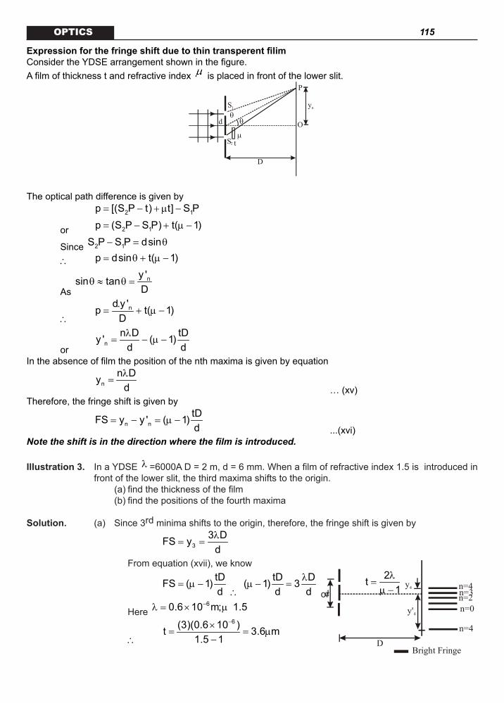
115 OPTICS
ExpressionforthefringeshiftduetothintransperentfilimConsider the YDSE arrangement shown in the figure. A film of thickness t and refractive index is placed in front of the lower slit.
d
S1
S2
D
O
P
θ
yn
θ
tµ
The optical path difference is given by
2 1p [(S P t) t] S P= − + µ −
or 2 1p (S P S P) t( 1)= − + µ −
Since 2 1S P S P dsin− = θ
∴ p dsin t( 1)= θ + µ −
As ny 'sin tan
Dθ ≈ θ =
∴ nd.y 'p t( 1)
D= + µ −
or n
n D tDy ' ( 1)d dλ
= − µ −
In the absence of film the position of the nth maxima is given by equation
n
n Dydλ
= … (xv)
Therefore, the fringe shift is given by
n n
tDFS y y ' ( 1)d
= − = µ − ...(xvi)
Note the shift is in the direction where the film is introduced.
Illustration 3. In a YDSE λ =6000A D = 2 m, d = 6 mm. When a film of refractive index 1.5 is introduced in front of the lower slit, the third maxima shifts to the origin.
(a) find the thickness of the film (b) find the positions of the fourth maxima
Solution. (a) Since 3rd minima shifts to the origin, therefore, the fringe shift is given by
3
3 DFS ydλ
= =
From equation (xvii), we know
tDFS ( 1)d
= µ − ∴
tD D( 1) 3d d
λµ − =
or
2t1
λ=
µ −
Here 60.6 10 m; 1.5−λ = × µ
∴
6(3)(0.6 10 )t 3.6 m1.5 1
−×= = µ
−Bright Fringe
n=4n=3n=2n=0
n=4
D
dy4
y'4

116 OPTICS (b) There are two positions of 4th maxima;
one above and the other below the origin.
4
Dy 1 0.2 mmd
λ= ω = =
4
Dy ' 7 1.4 mmd
λ= − ω = = −
LLOYD’S MIRRORd
P
OS1
S2
A plane grass plate (acting as a mirror) is illuminated at almost grazing incidence by a light from a slit S1. A virtual image S2 is formed closed to S1 by reflection and these two act as coherent sources. The expression giving the fringes width is the same as for the double slit, but the fringe system differs in one important respect. In Lloyd’s mirror, if the point P, for example, is such that the path difference S2 P – S1 P is a whole number of wavelengths, the fringe at P is dark not bright. This is due to 180º phase change which occurs when light is reflected from a denser medium. This is equivalent to adding an extra half wavelength to the path of the reflected wave. At grazing incidence a fringe is formed at O, where the geometrical path difference between the direct and reflected waves is zero and it follows that it will be dark rather than bright.
Thus, whenever there exists a phase difference of π between the two interfering beams of light, conditions of maximas and minimas are interchanged, i.e., x n∆ = λ (for minimum intensity)
and x (2n 1) / 2∆ = − λ (for maximum intensity)
Interferenceinthinfilms.
Interference effects are commonly observed in thin films, such as thin layers of oil on water or the thin surface of a soap bubble.
The varied colours observed when white light is incident on such films result from the interference of waves reflected from the two surfaces of the film.
Consider a film of uniform thickness t and index of refraction µ , as shown in figure. Let us assume that the light rays travelling in air are nearly normal to the two surfaces of the film. To determine whether the reflected rays interfere constructively or destructively, we first note the following facts.
1 2
A
BFilm
Air µ µair film<
Air
t
180º phasechange No phase
change
Interference in light reflected from a thin film is due to a combination of rays reflected from the upper and lower surfaces of the film.
(i) The wavelength of light in a medium whose refractive index is µ is,

117 OPTICS
µ
µλ =
µ
where λ is the wavelength of light in vacuum (or air)(ii) If a wave is reflected from a denser medium it undergoes a phase change of 180º. Let us apply
these rules to the film shown in figure. The path difference between the two rays 1 and 2 is 2t while the phase difference between them is 180º. Hence, condition of constructive interference will be,
2t (2n 1)
2µλ
= − n = 1, 2, 3, …
or
12 t n2
µ = − λ as
µ
λλ =
µ Similarly, condition of destructive interference will be,
2 t nµ = λ n = 0, 1, 2, …
KEY CONCEPTS
In case of superposition of two waves,
R 1 2 1 2I I I 2 I I cos= + + φ , or ( )2 2R 1 2 1 2I A A 2A A cos∝ + + φ
Condition for constructive interference
2 n,φ = ± π n = 1, 2, 3, ….( )x n∆ = ± λ , n = 1, 2, 3, ….
Condition for destructive interference
( )2n 1φ = ± − π , n = 1, 2, 3, ….( ) ( )x 2n 1 / 2∆ = ± − λ n = 1, 2, 3, …
Distance of nth bright fringe from C.B.F. is
( )n B
Dy n ,d
= ± λn = 0, 1, 2, 3, ….
Distance of nth dark fringe from C.B.F. is
( ) ( )n D
Dy 2n 12dλ
= ± +, n = 0, 1, 2, 3, ….
Fringe width , Angular fringe width =
Equivalent optical path of a medium of R.I, and distance d is .
Displacement of fringe pattern due to introduction of a transparent sheet of R.I. and thickness t in YDSE = y0 = ( – 1) t (D/d), in the same side in which the transparent sheet is introduced.
DCO
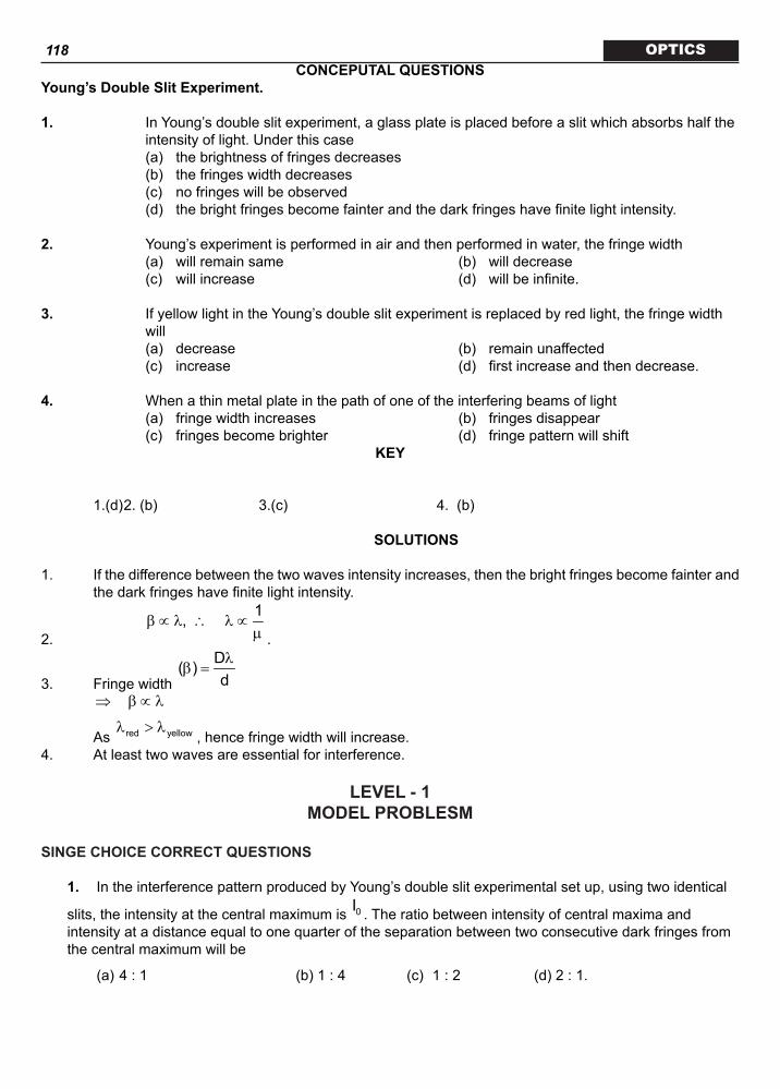
118 OPTICSCONCEPUTAL QUESTIONS
Young’s Double Slit Experiment.
1. In Young’s double slit experiment, a glass plate is placed before a slit which absorbs half the intensity of light. Under this case
(a) the brightness of fringes decreases (b) the fringes width decreases (c) no fringes will be observed (d) the bright fringes become fainter and the dark fringes have finite light intensity.
2. Young’s experiment is performed in air and then performed in water, the fringe width (a) will remain same (b) will decrease (c) will increase (d) will be infinite.
3. If yellow light in the Young’s double slit experiment is replaced by red light, the fringe width will
(a) decrease (b) remain unaffected (c) increase (d) first increase and then decrease.
4. When a thin metal plate in the path of one of the interfering beams of light (a) fringe width increases (b) fringes disappear (c) fringes become brighter (d) fringe pattern will shift
KEY
1.(d) 2. (b) 3.(c) 4. (b)
SOLUTIONS
1. If the difference between the two waves intensity increases, then the bright fringes become fainter and the dark fringes have finite light intensity.
2.
1,β ∝ λ ∴ λ ∝µ .
3. Fringe width
D( )dλ
β =
⇒ β ∝ λ
As red yellowλ > λ, hence fringe width will increase.
4. At least two waves are essential for interference.
LEVEL-1MODEL PROBLESM
SINGE CHOICE CORRECT QUESTIONS
1. In the interference pattern produced by Young’s double slit experimental set up, using two identical
slits, the intensity at the central maximum is 0I . The ratio between intensity of central maxima and intensity at a distance equal to one quarter of the separation between two consecutive dark fringes from the central maximum will be
(a) 4 : 1 (b) 1 : 4 (c) 1 : 2 (d) 2 : 1.

119 OPTICS
2. In Young’s double slit experiment, let 0I be the intensity at the central bright fringe and β be the fringe width. The intensity at a distance x from the central bright fringe will be
(a) 0
xI cos π β (b)
20
xI cos π β
(c)
20
x4I cos π β (d)
20I xcos2
π β .
3. In YDSE the fringe width is β . If the whole set-up is placed inside a transparent liquid of refractive index µ , the new fringe width will be
(a) (b) ( 1)µ − β (c) µβ (d) /β µ .
4. In double slit experiment with monochromatic light of wavelength λ , the shift in the fringe pattern is observed by introducing a thin mica sheet of thickness t and refractive index µ in the path of one of the interfering waves. When the mica sheet is removed the separation between the slits and the screen in doubled, it is found that the resulting fringe width is equal to the observed shift in the fringe pattern. The wavelength λ is given by
(a) ( 1)tµ − (b) 2( 1)tµ −
(c)
1 ( 1)t2
µ − (d) none of these.
5. In YDSE , films of thickness 1t and 2t and refractive indices 1µ and 2µ are placed in the path of
the two interfering beams of light. If 1 1 2 2t tµ = µ , then the central maximum will shift by
(a) 1 2t ~ t
λ fringes (b) 1 2t t2+λ fringes
(c) 1 1 2 2t tµ + µ
λ fringes (d) none of these.
MAY BE MORE THAN CORRECT CHOICE ANSWERS
θ
S1
S2
d2
d2
6. In an interference arrangement, similar to Young’s double slit
experiment, the slits 1S and 2S are illuminated with coherent microwave source, each of frequency 106 Hz. The source are synchronized to have zero phase difference. The slits are separated by distance d=150.0 m. The
intensity ( )I θ is measured as a function of θ , where θ is defined as shown
in figure. If 0I is maximum intensity, then ( )I θ for 0 90≥ θ ≤ is given by
(a) ( ) 0I Iθ = for =0θ ° (b) ( ) ( )0I I /2θ =
for =30θ °

120 OPTICS
(c) ( ) ( )0I I /4θ = for =90θ ° (d) ( )I θ is constant for all values of θ
7. In a Young’s double-slit experiment, let A and B be the two slits. A thin film of thickness t and
refractive index is placed in front of A. Let = fringe width. The central maximum will shift
(a) towards A (b) towards B
(c) by ( )t 1 βµ −
λ (d) by t β
µλ .
8. If white light is used in a Young’s double-slit experiment,
(a) bright white fringe is formed at the centre of the screen
(b) fringes of different colours are observed clearly only in the first order
(c) the first-order violet fringes are closer to the centre of the screen than the first-order red fringes
(d) the first-order red fringes are closer to the centre of the screen than the first-order violet fringes.
COMPREHENSION@ Write-up–1
In a young’s experiment the upper slit is covered by a thin glass plate of refractive index 1.4. Interference pattern is observed using light of interference 5000 Å.
9. The central maxima will shift (a) Upward
(b) Downward
(c) Fringe pattern will change after introduction of thin plate
(d) None of the above
10. Now a thin plate of refractive index 1.8 and the same thickness as the previous one, is placed in front of lower slit then
(a) Central maxima will be obtained below centre (b) Central maxima will be obtain at centre (c) There will not be any change in central maxima after introduction of thin plate (d) Cannot be predicted
11. Assume the thickness of both thin glass plate having refractive index 1.4 & 1.8 is t then path difference between waves incident at center is
(a) 0.5 t (b) 0.3 t
(c) 0.8 t (d) t1.7
1.5ASSERTION / REASONCodes. (a) Statement – 1 is True, Statement – 2 is True; Statement – 2 is a correct explanation for
Statement – 1. (b) Statement – 1 is True, Statement – 2 is True; Statement – 2 is NOT a correct explanation for
Statement – 1. (c) Statement – 1 is True, Statement – 2 is False. (d) Statement – 1 is False, Statement – 2 is True. 12. STATEMENT – 1

121 OPTICS
Two slits in YDSE are illuminated by two different sodium lamps emitting light of same wavelength. No interference pattern is observed.
STATEMENT – 2 To obtain interference pattern, source must be coherent. Two different light sources can never be
coherent.
13. STATEMENT – 1
Thin films such as soap bubble or a thin layer of oil on water show beautiful colours when illuminated by monochromatic light.
STATEMENT – 2
The colours are obtained by dispersion of light.
14. STATEMENT – 1
No interference pattern is detected when two coherent sources are infinitely close to each other.
STATEMENT – 2
The fringe width is inversely proportional to the distance between the two slits.
15. STATEMENT – 1
Light added to light can produce darkness.
STATEMENT – 2
The destructive interference of two coherent light sources may give dark fringes.
MATRIX MATCHEach question contains statements given in two column which have to be matched. Statements (a, b, c, d) in Column A have to be matched with statements (p, q, r, s) in Column B. The answers to these questions have to be appropriately bubbled as illustrated in the following example.
16.
Column – A Column – B (a) Wave nature of light (p) Young’s double slit experiment (b) Particle nature of light (q) Photoelectric effect (c) Wave nature of electrons (r) Electron microscope (d) Particle nature of electrons (s) Cathode rays
PRACTICAL QUESTIONSSINGE CHOICE CORRECT QUESTIONS
17. In a Young’s double-slit experiment comprising two identical slits 1S and 2S , a thin transparent film
of thickness t and refractive index µ is placed in front of 1S . If β be the fringe width in the interference pattern and λ = wavelength of light source the central fringe will shift
(a) towards 1S by t /µ β λ (b) towards 1S by ( 1)t /µ − β λ
(c) towards 2S by t /µ β λ (d) towards 2S by ( 1)t /µ − β λ .
18. In Young’s double slit experiment the 5th maximum with wavelength 1λ is at a distance 1d from the

122 OPTICS
centre of the fringe pattern and that with wavelength 2λ at a distance 2d , then the ratio 1 2d / d is
(a) 2 1/λ λ (b) 1 2/λ λ
(c) 2 22 1/λ λ (d)
2 21 2/λ λ .
19. In a double slit experimental set up producing interference pattern on a screen placed at a distance D meter from the two narrow slits which are d mater apart, N fringes were observed per meter using monochromatic light of wavelength λ , then the value of N is
(a) d / Dλ (b) D / dλ
(c) d / Dλ (d) D / dλ .
20. Consider a YDSE set up with a monochromatic source of wavelength 0λ in a liquid of refractive
index Lµ where the central maximum is located at 0P . If the slits are covered with thin transparent
plates of thickness 1t and 2t and refractive indices 1µ and 2µ such that 1 1 2 2 1 2t t (t t )µ − µ = − , then the position of the central maximum will shift by
(a)
1 1 2 2
0
t tµ − µλ fringes (b)
1 2 1 2
0
( )(t t )µ − µ −λ fringes
(c)
1 1
2 2
tt
µµ fringes (d) none of the above.
21. In the ideal double-slit experiment, when a glass-plate (refractive index 1.5) of thickness t is introduced in the path of one of the interfering beams (wave-length λ ), the intensity at the position where the central maximum occurred previously remains unchanged. The maximum thickness of the glass-plate is
(a) 2λ (b)
23λ
(c) 3λ
(d) λ
MAY BE MORE THAN CORRECT CHOICE ANSWERS
22. In the Young’s double slit experiment, the interference pattern is found to have an intensity ratio between the bright and dark fringes as 9. This implies that .
(a) the intensities at the screen due to the two slits are 5 units and 4 units respectively
(b) the intensities at the screen due to the two slits are 4 units and 1 unit respectively
(c) the amplitude ratio is 3
(d) the amplitude ratio is 2.
23. White light is used to illuminate the two slits in Young’s double slit experiment. The separation between the slits is b and the screen is at a distance d (>>b) from the slits. At a point on the screen directly in front of one of the slits, certain wavelengths are missing. Some of these missing wavelengths are.

123 OPTICS
(a) 2b / dλ = (b)
22b / dλ =
(c) 2b / 3dλ = (d)
22b / 3dλ = .
S1 S2O
24. Two point monochromatic and coherent sources of light of wavelength l are placed on the dotted line in front of an infinite screen. The source emit waves in phase with each other. The distance between S1 and S2 is d while their distance from the screen is much larger. Then,
(i) if d = 7l/2, O will be a minima
(ii) if d = 4.3l, there will be a total of 8 minima on screen
(iii) if d = 7l, O will be a maxima
(iv) if d = l, there will be only one maxima on the screen
which is the set of correct statement .
(a) (i), (ii) and (iii) (b) (ii), (iii) and (iv)
(c) (i), (ii), (iii) and (iv) (d) (i), (iii) and (iv)
COMPREHENSION@ Write-up–1
A monochromatic beam of light falls on Young’s double slit experiment apparatus as shown in figure. A thin sheet of glass is inserted in front of lower slit S2. ( = 600 nm is wavelength of source).
25. The central bright fringe can be obtained (a) at O (b) at O or below O (c) at O or above O (d) Anywhere on the screen
26. If central bright fringe is obtained on screen at O
(a) (b)
(c) (d)
t d1 sin
=µ − θ
27. The phase difference between central maxima and fifth minima is
(a) 6π
(b)
(c)
32π
(d)
28. Fringe width of the pattern obtained on screen if = 600 nm, = 1.5, d = 3mm (D = 2m = 30°)

124 OPTICS
(a) nm1054
4.5×
(b) 4 × 10⁵ nm
(c)
54 ×10 sin304.5 (d)
64 10 cos304.5×
29. Assume if is increased then (for given value of ) central maxima will move
π θ < 2 . (a) Downward (b) Upward (c) Fringe width will increases (d) Fringe width will decrease.
ASSERTION / REASON
Codes. (a) Statement – 1 is True, Statement – 2 is True; Statement – 2 is a correct explanation for
Statement – 1. (b) Statement – 1 is True, Statement – 2 is True; Statement – 2 is NOT a correct explanation for
Statement – 1. (c) Statement – 1 is True, Statement – 2 is False. (d) Statement – 1 is False, Statement – 2 is True.
30. STATEMENT – 1 Young’s double slit experiment can be performed using a source of white light. STATEMENT – 2 The wavelength of red light is less than the wavelength of other colours in white light.
31. STATEMENT – 1 Colours are seen in thin layers of oil on the surface of water STATEMENT – 2 White light is composed of several colours.
32. STATEMENT – 1 All bright interference bands have the same intensity. STATEMENT – 2 In interference all bands receive same light from two sources.
33. STATEMENT – 1 If the whole apparatus of Young’s experiment is immersed in liquid, the fringe width will decrease. STATEMENT – 2 The wavelength of light in water is more than that of air.
MATRIX MATCHEach question contains statements given in two column which have to be matched. Statements (a, b, c, d) in Column A have to be matched with statements (p, q, r, s) in Column B. The answers to these questions have to be appropriately bubbled as illustrated in the following example.34. In the YDSE appratus shown in the figure Dx is the path difference between S2P and S1P. Now a glass slab is introduced in front of S2, then match the following .
S1
S2
P
O

125 OPTICS Column – A Column – B (a) Dx at P will (p) increase (b) Fringe width will (q) decrease (c) Fringe pattern will (r) remain same (d) Number of fringes between O and P will (s) shift upward
LEVEL-1KEYMODEL QUESTIONS
SINGE CHOICE CORRECT QUESTIONS
1. (d) 2. (b) 3. (d) 4. (c) 5. (a)MAY BE MORE THAN CORRECT CHOICE ANSWERS
6. (a, b) 7. (a, c) 8. (a, b, c)
COMPREHENSION@ Write-up–1
9. (a) 10. (a) 11. (b)ASSERTION / REASON
12. (a) 13. (c) 14. (a) 15. (a)
MATRIX MATCH
16. (a – p) (b – q) (c – r) (d – s)
PRACTICAL QUESTIONS KEYSINGE CHOICE CORRECT QUESTIONS
17. (b) 18. (b) 19. (c) 20. (d) 21. (a)
MAY BE MORE THAN CORRECT CHOICE ANSWERS
22. (b, d) 23. (a, c) 24. (a,b)COMPREHENSION@ Write-up–1

126 OPTICS
25. (d) 26. (a) 27. (b) 28. (b) 29. (b)
ASSERTION / REASON
30. (c) 31. (b) 32. (c) 33. (c)
MATRIX MATCH
34. (a – p) (b – r) (c – t) (d – r)
MODEL PROBLEMSSINGE CHOICE CORRECT QUESTIONS
1. The resultant intensity r 1 2 1 2I I I 2 I I cos= + + φ
Here 1 2I I I= = , so rI 2I(1 cos )= + φ
At the central maximum, wave superpose in same phase,
i.e., 0φ =
0I 2I(1 cos ) 4I= + φ =
Now, at a distance equal to
14
× fringe width
14
= β from the central maximum, wave superpose with
phase difference
1 24 2
πφ = × π =
∴ I 2I(1 cos / 2)′ = + π 2I= , and the required ratio
0
4II / I 2 :12I
′ = =.
2. If I be the intensity from two coherent sources, the resultant intensity
rI I I 2Icos= + + φ
2I(1 cos )= + φ
24Icos2φ =
.
At the central maximum, r 0I I= and 0φ =
∴ 0I 4I=
At a distance x from the central fringe, path difference dsin dtan∆ = θ ≈ θ ∴ Phase difference

127 OPTICS
2 2 xd 2 xD (D / d)
π π πφ = ∆ = =
λ λ λ2 xπ
=β
∴ The intensity at point P will be
2 2P 0
x xI 4Icos I cos = π = π β β .
3. The fringe width 0D
dλ
β = where 0λ is the wavelength in free space. When the whole system is in a
liquid, only λ changes to
λ′λ =µ and
D Dd d
′λ λ β′β = = =µ µ .
4. If y be the shift in the fringe system,
( 1)t y d / Dµ − = ,
or,
( 1)Dtyd
µ −=
… (i) In the second case, fringe width
D (2D)d d′λ λ
β = = … (ii)
Equating (i) and (ii)
2D ( 1)Dtd d
λ µ −=
⇒
1 ( 1)t2
λ = µ −.
5. Optical path introduced by the plates are 1 1( 1)tµ − and 2 2( 1)tµ − . Net path difference introduced at
the previously occupied central fringe is 1 1 2 2( 1)t ( 1)t∆ = µ − − µ −
1 1 2 2 2 1( t t ) (t t )= µ − µ + −
Hence the displacement of the central maximum will be
Dyd
∆ ∆= = β
λ
1 2(t ~ t )
=λ fringes.
MAY BE MORE THAN CORRECT CHOICE ANSWERS
6. The intensity of light is I(q) = Io cos22δ
where d =
2πλ (Dx) =
2π λ (d sin )
(i) For = 30°
l =
cv =
8
6
3 1010×
= 300 m and d = 150 m
d =
2300
π (150)
12
= 2
π

128 OPTICS
\ 2δ
= 4π
\ = I0 cos2
0I4 2π =
(option a) (ii) For = 90°
d =
2300
π (150)(1) =
or 2δ
= 2π
and = 0
(iii) For = 0°, d = 0 or 2δ
= 0 \ I( ) = I0 (option c)
7. Change in yn
Dd
= × (change in path diff)
( )D 1 t
d= × µ − ( )1 tβ
= µ −π .
8. For central bright fringe, path diff. = 0 Violet light has lesser wavelength, so less path difference.
COMPREHENSION@Write-up–1
9. Because the slit is kept in front of upper slit so, to produce zero path diff central maxima will shift in upward dixetia.
10. The light emerging from the lower slit will be delayed more after passing through the glass plate of higher refractive index.
11. Change path diff.
( ) ( ){ }1.7 1 1.4 1 t= − − −
= 0.3 t. ASSERTION / REASON12. Two different sodium lamps are not coherent.13. The colours are obtained due to interference.14. The fringe width is inversely proportional to the separation of between the sources.
15. .
MATRIX MATCH16. The wave nature of light (or meter) is important in experiments that involve objects whose size is
comparable to the wavelength.PRACTICAL QUESTIONS HINTS/SOLUTIONS
SINGE CHOICE CORRECT QUESTIONS
17 Initially, the path difference at the central maximum was zero. Introduction of thin film in front of 1S

129 OPTICS
produces a path difference ( 1)t∆ = µ − and hence to compensate the path, central fringe will shift
towards 1S by and amount
y ∆
= βλ ( 1)t /= µ − β λ .
18. 1
1 1Dd 5 5
dλ
= β =
2
2 2Dd 5 5
dλ
= β =
∴
1 1
2 2
dd
λ=
λ .
19. Fringe width
Ddλ
β = meter hence
Ddλ
meter comprises one fringe, hence 1 meter will comprise
dDλ
number of fringes.
Hence
dND
=λ .
20. Optical path introduced by the two plates are 1 L 1( )tµ − µ and 2 L 2( )tµ − µ . Hence the shift of the central maximum will be
0
y ∆= β
λ
1 L 1 2 L 2
0
( )t ( )tµ − µ − µ − µ=
λ fringes.
21. Path difference introduced at the position of previously occupied central maximum is ( 1)tµ − . For maximum intensity at this point, the path difference
( 1)t nµ − = λ , where n 1,2,....=
∴min(t)
1 (1.5 1)λ λ
= =µ − − 2= λ .
MAY BE MORE THAN CORRECT CHOICE ANSWERS
22.
max
min
II =
( )( )
2
1 2
2
1 2
I I
I I
+
−
=
2
1 2
1 2
I I 1I I 1
+ − = 9 (Given)
Solving this, we have
1
2
II = 4
but I A2
\
1
2
AA = 2
23. At P (directly in front of S1)
y=
b2

130 OPTICS \ Path difference,
DX = S2P – S1P =
b (b)y.(b) 2
d d
=
=
2b2d
Those wavelengths will be missing for which
DX = 31 2 53, ,
2 2 2λλ λ
…
\ l1 = 2Dx =
2bd
l2 =
2 x3∆
=
2b3d
l3 =
22 x b5 5d∆
=
\ correct options are (a) and (c)24. For point O, path diff = d
For minima,
( )2n 1d
2− λ
=
N = 1, 2, 3, 4….
7d2λ
=
For another point, ad for path diff. = d sin q = (2n –1) 2λ
( )2n 1sin
2d− λ
θ =, n = 1, 2, 3, 4, …
For maxima,
nsindλ
θ =.
COMPREHENSION@ Write-up–1
25. Anywhere on screen because there is no relation between 26. Total path difference
Dx = Dx = for central maxima27. D = (2n -1) Here n = 5
28. fringe width =
ëDd
54 10= ×
29. Dx = d sin - ( -1)t if increases then will increase, this will shift central maxima upward.
ASSERTION / REASON30. The wavelength of red light is a maximum.31. Colours in the films are due to interference. 32. Near the central maximum, the intensity of bright fringes remains the same.33. The speed of light in water is less than that in air, but the freqeuncy remains unchanged.
MATRIX MATCH
34. The optical path between S2 and P is increased due to the glass slab, and the order of the fringe at P

131 OPTICS
is increased. Fringe width remains unchanged.LEVEL-II
MODEL QUESTIONSSINGLE CHOICE CORRECT QUESTIONS
1. Which of the following is not an essential condition for sustained interference? (a) The two interfering waves must be propagated in almost the same direction or the two interfering
waves must intersect at very small angle. (b) The wave must have the same period and wavelength (c) The amplitude of the two waves must be equal (d) The two interfering beams of light must originate from the same source
2. Interference fringes are obtained in Young’s double slit experiment on a screen. Which of the following statements will not be correct about the effect of a thin transparent plate when placed in the path of one of the two interfering beams?
(a) The separation between fringes remains unaffected. (b) The entire fringe system shifts towards the side on which the plate is placed.
(c) The condition for maxima and minima are reversed i.e., maxima for odd multiple of 2λ
and minima
for even multiple of 2λ
. (d) The shape of the fringe also remains unaffected.
3. In a Young’s double-slit experiment, if the slits are of unequal width, (a) fringes will not be formed (b) the positions of minimum intensity will not be completely dark (c) bright fringe will not be formed at the center of the screen (d) distance between two consecutive bright fringes will not be equal to the distance between two
consecutive dark fringes.
4. Interference patterns are not observed in thick films, because (a) most of the incident light intensity is absorbed within the film (b) a thick film has high coefficient of reflection (c) coherence is lost (d) maxima of interference patterns are far from the minima.
MAY BE MORE THAN CORRECT CHOICE ANSWERS
5. Which of the following can give sustained interference? (a) Two independent laser sources (b) Two independent light bulbs (c) Two independent sound sources (d) Two independent microwave sources
6. Two monochromatic coherent point sources S1 and S2 are separated by a distance L. Each source emits light of wavelength l; where L >> l. The line S1S2 when extended meets a screen perpendicular to it at a point A.
(a) the interference fringes on the screen are circular in shape (b) the interference fringes on the screen are straight lines perpendicular to the line S1S2A (c) the point A is an intensity maxima if L = nl (d) the point A is always an intensity maxima for any separation L.

132 OPTICS
7. A long narrow horizontal slit lies 1 mm above a plane mirror. The interference pattern produced by the slit and its image is viewed on a screen distant 1m from the slit. The wavelength of light is 600 nm. Then the distance of the first maxima above the mirror is equal to.
(a) 30 mm (b) 0.15 mm (c) 60 mm (d) 0.75 mm.
COMPREHENSION@ Write-up–1
In a Young’s double slit experiment set up, source S of wavelength 6000Å illuminates two slits S1 and S2 which act two coherent sources. The source S oscillates about its shown position according to the equation y = 1 + cos t where y is in millimeters and t in seconds.
8. At t = 0, fringe width is b1, and at t = 2 seconds, fringe width of figure is b2. Then (a) b1 > b2 (b) b2 > b1 (c) b1 = b2 (d) Data is insufficient.
9. At t = 2 second, the position of central maxima is (a) 2 mm above the C (b) 2 mm below the C (c) 4 mm below the C (d) 4 mm below the C.
10. At t = 1 second, a slab of thickness 2 × 10⁻³ mm and refractive index 1.5 is placed in just front of S1. The central maxima is formed at
(a) 1 mm above the C (b) 1 mm below the C (c) 2 mm above the C (d) 2 mm below the C.
ASSERTION / REASON
Codes. (a) Statement – 1 is True, Statement – 2 is True; Statement – 2 is a correct explanation for
Statement – 1. (b) Statement – 1 is True, Statement – 2 is True; Statement – 2 is NOT a correct explanation for
Statement – 1. (c) Statement – 1 is True, Statement – 2 is False. (d) Statement – 1 is False, Statement – 2 is True.
11. STATEMENT – 1 The film which appears bright in reflected system will appear dark in the transmitted light and vice-
versa. STATEMENT – 2 The conditions for film to appear bright or dark in reflected light are just reverse to those in the
transmitted light.
12. STATEMENT – 1 For best contrast between maxima and minima in the interference pattern of Young’s double slit

133 OPTICSexperiment, the intensity of light emerging out of the two slits should be equal.
STATEMENT – 2 The intensity of interference pattern is proportional to square of amplitude.
13. STATEMENT – 1 In Young’s double slit experiment, the fringes become indistinct if one of the slits is covered with
cellophane paper. STATEMENT – 2 The clear cellophane paper decrease the wavelength of light.
14. STATEMENT – 1 In Young’s double slit experiment the two slits are at distance d apart. Interference pattern is
observed on a screen at distance D from the slits. At a point on the screen when it is directly opposite to one of the slits, a dark fringe is observed. Then the wavelength of wave is proportional to square of distance of two slits.
STATEMENT – 2 For a dark fringe intensity is zero.
15. STATEMENT – 1 If the phase difference between the light waves emerging from the slits of the Young’s experiment is
radian, the central fringe will be dark. STATEMENT – 2
Phase difference is equal to times of path difference.
MATRIX MATCHEach question contains statements given in two column which have to be matched. Statements (a, b, c, d) in Column A have to be matched with statements (p, q, r, s) in Column B. The answers to these questions have to be appropriately bubbled as illustrated in the following example.
16. In case of Young’s double slit arrangement match the following facts
PRACTICE QUESTIONS
SINGLE CHOICE CORRECT QUESTIONS

134 OPTICS17. If one of the two slits of a Young’s double slit experiment is painted over so that it transmits half the
light intensity as compared to that of the other, then (a) The fringe system would disappear (b) The bright fringes will be more bright & dark fringes will be more dark (c) The dark fringes would be less dark and bright fringes would be less bright (d) Bright as well as dark fringes would be darker.
18. In Young’s double slit experiment, the constant phase difference between two sources is .
2π
The
intensity at a point equidistant from the slits in terms of maximum intensity 0I is
(a) 0I (b) 0I2
(c) 03I
4 (d) 03I
BS1
S2
Q
P
O
19. In the figure, Young’s double slit experiment Q is the position of the first bright fringe on the right side of O.P is the 11th fringe on the other side,
as measured from Q. If 6000A°λ = , then 1S B will be equal to (a)
66 10 m−× (b) 66.6 10 m−×
(c) 73.318 10 m−× (d)
73.144 10 m−×
20. In a Young’s double-slit experiment, the central bright fringe can be identified (a) as it has greater intensity than the other bright fringes (b) as it wider than the other bright fringes (c) as it is narrower than the other bright fringes (d) by using white light instead of monochromatic light.
MAY BE MORE THAN CORRECT CHOICE ANSWERS
21. Four light waves are represented by
(i) y = a1 (ii) y = a2
(iii) y = a1 (iv) y = a2 Interference fringes may be observed due to superposition of (a) (i) and (ii) (b) (i) and (iii) (c) (ii) and (iv) (d) (iii) and (iv).
22. Identify the correct statements related to Young’s double slit experiment (a) the initial phase difference between the two sources should be constant (b) the distance between two successive maxima or minima is constant (c) the angular fringe width d is independent of the order n of maxima
(d) the fringe width is given by .
23. As a wave propagates. (a) the wave intensity remains constant for a plane wave (b) the wave intensity decreases as the inverse of the distance from the source for a spherical wave (c) the wave intensity decreases as the inverse square of the distance from the source for a
spherical wave (d) total intensity of the spherical wave over the spherical surface centred at the source remains
constant at all times.
COMPREHENSION

135 OPTICS@ Write-up–1
A thin film of a specific material can be used to decrease the intensity of reflected light. There is destructive interference of waves reflected from upper and lower surfaces of the film. These films are called non–reflecting or antireflection coatings. The process of coating the lens or surface with non–reflecting film is called blooming as shown in the figure. The refracting index of coating (n1) is less than that of the glass (n2).
Film
Glass
R.I. = n1
1 2
R.I. = n2
Air
24. If the light of wavelength l is incident normally and the thickness of film is ‘t’ then optical path difference between waves reflected from upper and lower surface of film is
(a) 2n1t (b) 12n t
2λ
−
(c) 12n t
2λ
+ (d) 2t.
25. Magnesium fluoride (MgF2) is generally used as anti–reflection coating. If refractive index of MgF2 is 1.38 then minimum thickness of film required is (Take = 550 nm) .
(a) 112.4 nm (b) 78.2 nm (c) 99.64 nm (d) 225 nm.
26. If the thickness of film in above question is not technologically possible to manufacture, then next thickness of film required is (approximately)
(a) 298.9 nm (b) 271.7 nm (c) 304.7 nm (d) 550 nm.
ASSERTION / REASONCodes. (a) Statement – 1 is True, Statement – 2 is True; Statement – 2 is a correct explanation for
Statement – 1. (b) Statement – 1 is True, Statement – 2 is True; Statement – 2 is NOT a correct explanation for
Statement – 1. (c) Statement – 1 is True, Statement – 2 is False. (d) Statement – 1 is False, Statement – 2 is True.
27. STATEMENT – 1 The maximum intensity in interference in an interference pattern is four times the intensity due to
each slit. STATEMENT – 2 Intensity is directly proportional to square of amplitude.
28. STATEMENT – 1 When monochromatic light is incident on a surface separating two media, the reflected and refracted
light both have the same frequency as the incident frequency. STATEMENT – 2 The frequency of monochromatic light depends on media.

136 OPTICS29. STATEMENT – 1 No interference pattern is detected when two coherent sources are infinitely close to each other. STATEMENT – 2 The fringe width is inversely proportional to the distance between the two coherent sources.
30. STATEMENT – 1 For best contrast between maxima and minima in the interference pattern of Young’s double slit
experiment, the intensity of light emerging out of the two slits should be equal. STATEMENT – 2 The intensity of interference pattern is proportional to square of amplitude.
MATRIX MATCHEach question contains statements given in two column which have to be matched. Statements (a, b, c, d) in Column A have to be matched with statements (p, q, r, s) in Column B. The answers to these questions have to be appropriately bubbled as illustrated in the following example.
31. Match the column
LEVEL-IIKEY
MODEL QUESTIONSSINGE CHOICE CORRECT QUESTION
1. (c) 2. (c) 3. (b) 4. (c)
MAY BE MORE THAN CORRECT CHOICE ANSWERS
5. (a, c, d) 6. (a, c) 7. (b)
COMPREHENSION@ Write-up–1
8 (c) 9. (d) 10. (a)
ASSERTION / REASON
137 OPTICS 11. (a) 12. (b) 13. (c) 14. (b) 15. (b)
MATRIX MATCH 16. (a – q) (b – r) (c – p) (d – s)
PRACTICE QUESTIONSKEY
SINGE CHOICE CORRECT QUESTIONS
17. (c) 18. (b) 19. (a) 20. (d)
MAY BE MORE THAN CORRECT CHOICE ANSWERS
21. (a, d) 22. (a, b, c, d) 23. (a, c, d)
COMPREHENSION@ Write-up–1
24. (a) 25. (c) 26. (a)
ASSERTION / REASON
27. (b) 28. (c) 29. (a) 30. (b)
MATRIX MATCH
31. (a – s) (b – p) (c – r) (d – q)

138 OPTICS
LEVEL-II
LEVEL-IIHINTS AND SOLUTIONS
MODEL QUESTIONSSINGE CHOICE CORRECT QUESTIONS
1. For sustained interference waves must be coherent2. The condition for maxima and minima formed by refracted light is not reversed.
3. ( )2
min 1 2I I I= −
4. Coherence is lost for a duration of time.
MAY BE MORE THAN CORRECT CHOICE ANSWERS
5. For sustained interference, sources must be coherent. 6. All points lying on any circle on the screen, concentric with A are symmetric with respect to S1 S2. Path
difference = nl, for maximum.
7. 1
Dy4dλ
= = 1.5 mm.
COMPREHENSION@ Write-up–1
8. to 10.
Position of central maxima at any time is y¢ = – 2 (1 + t) mm at t = 2 seconds, y¢ = – 4 mm. at t = 1 second Central maxima is at y¢ = 0 But when a plate is inserted Central maxima is at
1
Dy ( 1)td
= µ − = 1 mm.
ASSERTION / REASON
11. The phase is reflected light and transmitted light differ by 180º at the air-film barrier.
12. The visibility of the fringes is difined by : and the contrast of the fringe system is higher when visibliity is higher.
13. Contrast is reduced when the intensities of light emerging from the slits are not equal.
14. .
15. path difference.MATRIX MATCH
16. Independent sources are not choherent, in general. When white light is used in Young’s doulbe slit experiment, coloured fringes are obtained (except for the central fringe). A diffraction pattern is obtained

139 OPTICS
with a single slit. The contrast depends on the relative intensities of light from the two slits.CE QU
PRACTICAL QUESTIONSHINTS AND SOLUTIONS
SINGE CHOICE CORRECT QUESTIONS
17. ( )2
min 1 2I I I= −
( )2
max 1 2I I I= +.
18. 2
0I I cos2φ
=
2
0I cos4π =
0I2
=.
19. n
10 D Dy xd dλ
= = ∆
x 10∆ = λ
66 10 m−= × .
20. Because after using white light central bright fringe will be white due to zero path difference for all colours.
MAY BE MORE THAN CORRECT CHOICE ANSWERS
21. For superposition waves must be coherent (i.e., must have same frequency) 22. For sustained interference, waves must be coherent and fringe width doesn’t depend upon order n. 23. For plane wave, For sphericalwave,
I = const, 2
PIr
∝
COMPREHENSION@ Write-up–1
24. OPD = 2 n1t (a)25. For destructive interference,
1 min 1 22n t ( n n )
2λ
= <
min
550t 99.64 nm4 1.38
∴ = =× .
26. 1
32n t2λ
=
mint 3t 298.9nm⇒ = ≅ .
ASSERTION / REASON
27. .28. Frequency remains unchanged during reflection and refraction.29. In this case intensity will be same at each point on the screen.

140 OPTICS
30. Contrast is better when visibility is high.
MATRIX MATCH
31. A line source produces a cylindrical wave front while a point source produces spherical wavefront.
Contrast is better when visibility is high
.
LEVEL-IIIMODEL QUESTIONS
SINGE CHOICE CORRECT QUESTIONS1. In Young’s double slit experiment, 12 fringes are observed to be formed in a certain segment of the
screen when light of wavelength 600 nm is used. If the wave length of light is changed to 400 nm, number of fringes observed in the same segment of the screen is given by
(a) 12 (b) 18 (c) 24 (d) 30.2. Two beams of light having intensities I and 4I interfere to produce a fringe pattern on a screen.
The phase difference between the beams is / 2π at point A and π at point B. Then the difference between the resultant intensities at A and B is
(a) 2 I (b) 4 I (c) 5 I (d) 7 I.
3. In Young’s double slit experiment the wavelength of light was changed from 7000 A° to 3500 A° . While doubling the separation between the slits, which of the following is not true for this experiment?
(a) The width of fringes changes (b) The colour of bright fringes changes (c) The separation between successive bright fringes changes. (d) The separation between successive dark fringes remains unchanged.
4. In the ideal double slit experiment, when a glass plate of refractive index 1.5 and thickness t is introduced in the path of one of the interfering beams of wavelength λ , the intensity at the position of central maxima, remains unchanged. Minimum thickness of glass plate is
(a) 2 λ (b) 2 / 3λ (c) / 3λ (d) λ .
A
B BA
C
5. A ray of light of intensity I is incident on a parallel glass slab at a point A as shown. It undergoes partial reflection and refraction. At each reflection, 25% of incident energy is reflected. The rays AB and A B′ ′ undergo interference (see figure). The ratio of their intensities is
(a) 4 : 3 (b) 8 : 1 (c) 7 : 1 (d) 49 : 1.
MAY BE MORE THAN CORRECT CHOICE ANSWERS
6. If the width of slit S1 in Young’s double slit experiment is gradually increased.

141 OPTICS
(a) bright fringes become brighter and dark fringes become darker.
(b) Bright fringes become less bright , dark fringes become less dark.
(c) Bright fringes become brighter, dark fringes lighter.
(d) Bright fringes become less bright, dark fringes darker.
7. A light wave can travel
(a) in vacuum (b) in vacuum only
(c) in a material medium (d) in a material medium only.
8. Which of the following properties of light conclusively support wave theory of light?
(a) Light obeys laws of reflection
(b) speed of light in water is smaller than the speed in vacuum
(c) light shows interference
(d) light shows photoelectric effect.
COMPREHENSION@ Write-up–1
In Young’s experiment, light of wavelength 6000Å is incident on the double slits. Intensity of central maximum, formed at O, is I0, and the angular fringe–width is 0.1º. If a thin transparent plate A is placed in the path of one of the interfering beams, it is found that smallest thickness of the plate, for which intensity at O becomes half of maximum, is 250 nm. Also, the zero order fringe earlier at O now forms 0.5 mm from O.
O
S1
S2
d
DD >> d
However, instead of plate A, if a plate B made of another material is placed in the path of one of the interfering beams, smallest thickness of B for which intensity at O becomes zero is 300 nm. Neglect absorption of light by the plates and consider the following situations.
Answer the following questions .
9. Refractive index of plate A is (a) 1.4 (b) 1.5

142 OPTICS (c) 1.6 (d) 1.82.
10. Refractive index of plate B is (a) 2 (b) 1.8 (c) 1.65 (d) 1.48
11. If plate A is kept in front of S1 and plate B in front of S2 then intensity at O is (a) I0 (b) I0/2 (c) I0/4 (d) I0/8.
ASSERTION / REASONCodes. (a) Statement – 1 is True, Statement – 2 is True; Statement – 2 is a correct explanation for
Statement – 1. (b) Statement – 1 is True, Statement – 2 is True; Statement – 2 is NOT a correct explanation for
Statement – 1. (c) Statement – 1 is True, Statement – 2 is False. (d) Statement – 1 is False, Statement – 2 is True.
12. STATEMENT – 1 In Young’s double slit experiment the fringes become indistinct if one of the slits is covered with
cellophane paper. STATEMENT – 2 The cellophane paper decreases the wavelength of light.
13. STATEMENT – 1
In interference all the fringes are of same width
STATEMENT – 2
In interference fringe width is independent of position of the fringe.
14. STATEMENT – 1
One of the condition for interference is that the two slits should be very narrow.
STATEMENT – 2
Fringe width is inversely proportional to separation between slits.
15. STATEMENT – 1
Interference obeys the law of conservation of energy
STATEMENT – 2
The energy is redistributed in case of interference.
MATRIX MATCHEach question contains statements given in two column which have to be matched. Statements (a, b, c, d) in Column A have to be matched with statements (p, q, r, s) in Column B. The answers to these questions have to be appropriately bubbled as illustrated in the following example.
16. Match the column

143 OPTICS
SINGE CHOICE CORRECT QUESTIONS
17. In Young’s double slit experiment, the slits are illuminated by white light. The distance between two slits is d and screen is D distance away from the slits. Some wavelengths are missing on the screen in front of one of the slits. These wavelengths are
(a)
2 2d d,D 3D
λ = (b)
22dD
λ =
(c)
22d3D
λ = (d)
2 2d d,D 2D
λ =.
18. White light is incident on a soap film of thickness 55 10−× cm and refractive index 1.33. Which
wavelength is reflected maximum in the visible region ?
(a) 2600 °A (b) 8866 °A
(c) 5320 °A (d) 3800 °A .
s1
s2
Oθ
19. A monochromatic beam of light falls on Young’s double slit experiment apparatus at some angle (say ) as shown in the figure. A thin sheet of glass is inserted in front of the lower slit S2. The central bright fringe (path difference = 0) will be obtained
(a) anywhere depending on angle thickness of plate t and refractive index of glass
(b) at O (c) below O (d) above O
20. Young’s double slit experiment is performed in a liquid. The 10th bright fringe in liquid lies where 6th dark fringe lies in vacuum. The refractive index of the liquid is approximately
(a) 1.2 (b) 1.67 (c) 1.5 (d) 1.8
21. Two identical coherent sources are placed on a diameter of a circle of radius R at separation ( )x R<< symmetrically about the center of the circle. The sources emit identical wavelength λ

144 OPTICS
each. The number of points on the circle with maximum intensity is ( )x 5= λ
(a) 24 (b) 20 (c) 22 (d) 26.
θθd
P
22. A plane wave front of light is incident on a plane mirror as shown in the figure. Intensity is maximum at P when
(a) cos / 2d= λ (b) cos 3 / 4dθ = λ
(c) sec cos 3 / 4dθ − θ = λ (d) sec cos / 2dθ − θ = λ
23. In Young’s double slit experiment, the y coordinates of central maxima and 10th maxima are 2 cm and 5 cm respectively. When the apparatus is immersed in a liquid of refractive index 1.5, the corresponding y-coordinates will be
(a) 2 cm, 4 cm (b) 4/3 cm, 10/3 cm (c) 2 cm, 7.5 cm (d) 3 cm, 6 cm.
24. A plate of thickness t made of a material of refractive index µ is placed in front of one of the slits in a double slit experiment. What should be minimum thickness t, which will make the intensity at the centre of the fringe pattern zero ?
(a) ( )1
2λ
µ − (b) ( )1
λµ −
(c) ( )2 1λ
µ − (d) ( )1µ − λ .
C
S
S
1
2
I0
I0
I0
I0
dS3
S4
Dd
λ2
D
25. In the given figure, C is middle point of line 1 2S S . A monochromatic
light of wavelength λ in incident on slits. The ratio of intensity at 3S
and 4S is (a) 0 (b) ∞ (c) 4 . 1 (d) 1 . 4.
MAY BE MORE THAN CORRECT CHOICE ANSWERS
26. When light propagates in vacuum there is an electric field and a magnetic field. These fields (a) are constant in time (b) have zero average value (c) are perpendicular to the direction of propagation of light. (d) are mutually perpendicular
27. Huygens’ principle of secondary wavelets may be used to (a) find the velocity of light in vacuum (b) explain the particle behaviour of light (c) find the new position of a wavefront (d) explain Snell’s law.
28. Three observers A, B and C measure the speed of light coming from a source to be vA, vB and vC.

145 OPTICS
The observer A moves towards the source and C move away from the source at the same speed. The observer B stays stationary. The surrounding space is water everywhere. Select the correct option(s) from the list given in that question.
(a) vA > vB > vC (b) vA > vB > vC
(c) vA = vB = vC (d) vB = ( )A C
1 v v2
+.
COMPREHENSION@Write-up–1
The Young’s double-slit experiment is done in a medium of refractive index 4/3. A light of 600 nm wavelength is falling on the slits having 0.45 mm separation. The lower slit s2 is covered by a thin glass sheet of thickness 10.4 mm and refractive index 1.5. The interference pattern is observed on a screen placed 1.5 m from the slits. All the wavelengths given in this are for the given medium of refractive index 4/3. Ignore dispersion.
29. The location of the central point maximum (bright fringe with zero path difference) on the y-axis is.
(a) 4.33 mm (b) 3.44 mm
(c) 4.033 mm (d) 3.044 mm.
30. The light intensity at central point of screen relative to the maximum fringe intensity is given by.
(a) 0.50 (b) 0.75
(c) 0.25 (d) 1.00
31. Now, if 600 nm light is replaced by white light of range 400 to 700 nm, find the wavelengths of the light that forms maxima exactly at central point.
(a) = 650 nm and 434.4 nm (b) = 450 nm and 434.4 nm
(c) = 850 nm and 234.4 nm (d) = 250 nm and 234.4 nm.
ASSERTION / REASONCodes. (a) Statement – 1 is True, Statement – 2 is True; Statement – 2 is a correct explanation for
Statement – 1. (b) Statement – 1 is True, Statement – 2 is True; Statement – 2 is NOT a correct explanation for
Statement – 1. (c) Statement – 1 is True, Statement – 2 is False. (d) Statement – 1 is False, Statement – 2 is True.
32. STATEMENT – 1
In Young’s double slit experiment interference pattern disappears when one of the slits is closed
STATEMENT – 2
Interference occurs due to superimposition of light wave from two coherent sources
33. STATEMENT – 1
If the phase difference between the light waves emerging from the slits of the Young’s experiment is p- radian, the central fringe will be dark.
STATEMENT – 2

146 OPTICS
Phase difference is equal to
2πλ times the path difference.
34. STATEMENT – 1
Interference pattern is obtained on a screen due to two identical coherent sources of monochromatic light. The intensity at the central part of the screen becomes one half if one of the sources is blocked.
STATEMENT – 2
The resultant intensity is the sum of the intensities due to two sources; if one is blocked the intensity obviously reduces to one-half.
MATRIX MATCHEach question contains statements given in two column which have to be matched. Statements (a, b, c, d) in Column A have to be matched with statements (p, q, r, s) in Column B. The answers to these questions have to be appropriately bubbled as illustrated in the following example.
35. Match the column
LEVEL-IIIKEYMODEL QUESTIONS
SINGLE CHOICE CORRECT QUESTIONS
1. (b) 2. (b) 3. (d) 4. (a) 5. (b)
MAY BE MORE THAN CORRECT CHOICE ANSWERS
6. (c) 7. (a, c) 8. (b, c)COMPREHENSION@ Write-up–1
9. (c) 10. (a) 11. (b)ASSERTION / REASON
12. (c) 13. (a) 14. (a) 15. (a)
MATRIX MATCH
16. (a – q) (b – s) (c – r) (d – p)

147 OPTICS
PRACTICE QUESTIONS KEYSINGE CHOICE CORRECT QUESTIONS 17. (a) 18. (c) 19. (a) 20. (b) 21. (b) 22. (a) 23. (b) 24. (c) 25. (b)
MAY BE MORE THAN CORRECT CHOICE ANSWERS 26. (b, c, d) 27. (c, d) 28. (a, d)
COMPREHENSION@ Write-up–1 29. (a) 30. (b) 31. (a)ASSERTION / REASON 32. (a) 33. (b) 34. (d)MATRIX MATCH 35. (a – r) (b – q) (c – p)
LEVEL-IIISOLUTIONSMODEL QUESTIONS
SINGLE CHOICE CORRECT QUESTIONS
1.
12 600D n 400Dd d
× ×=
n 18= .
2. netI | (I 4I) (I 4I 2 I 4Icos ) | 4I= + − + + × π = .
3.
Dd
λβ =
If d will change, width of fringe will change.
4. 2
mdI I cos2
=
For I to be Im, 2 ,φ = π
(1.5 1)t− = λ
t3 12
π=
− .

148 OPTICS
5.
2
max2
min
I 3 I2 8I 49
I 1I 3 I2 8
+
= =
− .
MAY BE MORE THAN CORRECT CHOICE ANSWERS
6. 2 2
max 1 2 min 1 2I ( I I ) , I ( I I )= + = −
Here, I1 will increase that’s why Imax and Imin will increase.7. Light is an electromagnetic wave which can travel in vacuum and in a material medium also.8. In interference, fringes are formed which is the proof of continuous energy distribution i.e., wave theory
of light.
COMPREHENSION@Write-up–1
9. Here,
, x
2 4π λ
φ = ∆ =.
mII2
=,
( )A I t
4λ
µ − =
( )
102
A6000 101 250 10
4
−− ×
µ − × × =.
10. A 1.6µ =
, x
2λ
φ = π ∆ =
( )
109
B6000 101 300 10
2
−− ×
µ − × × =.
11. x
2 4 4λ λ λ
∆ = − =.
2π
φ =
0II2
=.
ASSERTION / REASON
12. The contrast between maximum and minimum intensity reduces as a result of covering one of the slits with cellophase paper.
13. near the central maximum.

149 OPTICS
14. for small d, W will be large.15. In interference, the energy is more at maximum while it is less at minima.
MATRIX MATCH
16.
and Also .
PRACTICE QUESTIONSHINTS AND SOLUTIONS
SINGLE CHOICE CORRECT QUESTIONS
17.
d (2n 1) D2 2d
− λ=
n = 1, 2, 3, … .
18. 2 t n
2λ
µ + = λ (for maxima)
4 t2n 1
µ⇒ λ =
− .19. x 0∆ =
dsin ( 1)t 0θ − µ − =
So, anywhere depending on angle θ thickness of plate t and refractive index of glass µ .
20.
10 D 11 D 11,d 2d 20λ λλ
= =λ
2011
µ =.
21.
P
θS1 S2
5λ
x 5 cos∆ = λ θ at P and 5 cos nλ θ = λ for maxima
n 20⇒ = .
22. At P, x dsec cos2 dsec
2λ
∆ = θ θ + θ +
2dcos
2λ
= θ +

150 OPTICS
for maxima, 2dcos n
2λ
θ + = λ.
23. y maxima = 2 / 1.5 = 4/3 y10th maxima = 5 / 1.5 = 10/3
24. ( 1)t
2λ
µ − =
or, t
2( 1)λ
=µ − .
25.
3
4
S 0
S
I 4II 0
= = ∞.
MAY BE MORE THAN CORRECT CHOICE ANSWERS
26. The coverage value of a sinusoidal function is zero; v, E, B
are mutually perpendicular. 27. From Huygen’s construction.28. Here, velocity of light in medium will be less than C. That’s why we can use the relative motion concept.
COMPREHENSION@ Write-up–1
29.
63 3x 1 10.4 102 4
− ∆ = × − × ×
n
Dy x 4.33 mmd
= ∆ =.
30.
2 xπφ = ∆
λ
2
md 3I I cos2 4
= =.
31.
63 3x 1 10.4 10 n2 4
− ∆ = × − × × = λ n = 1, 2, 3, ….
650 nm, and 34.4 nmλ = .ASSERTION / REASON32. At least two waves are necessary for interference. 33. If the phase difference is rad. It means waves superimpose in opposite phase.34. If one of these slits is closed, intensity becomes one fourth
.MATRIX MATCH35. The phenomena which can be explained by wave theory are reflection, refraction, interference etc. and
the phenomena which can be explained by particle nature of light is photoelectric effect.
INTEGER ANSWER TYPE QUESTIONSMODEL QUESTIONS

151 OPTICS
1. A thin wafer of 9.9 m thickness and refractive index 1.5 is introduced in front of one of the slits in a young’s double-slite experiment. By how many fringe widths does the fringe pattern shift ?
2. LIght used in a young’s double-slit experiment consists of two wavelengths . 450nm and 720nm. In the interference pattern , eighth maximum of the first coincides with the nth maximum of the second. What is n ?
3. In YDSE, d = 2 mm, D = 2m and 500nmλ = . If intensity of two slits are I0 and 9 I0 then the intensity
at
1y mm6
= is K I0. Find ‘K’.
4. Two identical coherent sources of wavelength λ are placed at (100 , 0)λ and ( 50 ,0)− λ
respectively. A detector moves slowly from origin to (2 , 0)λ along x–axis. The number of maximas
detected [including origin and (2 , 0)λ ] are
PRACTICE QUESTIONSA
B
C
DP
d/2
d/2
ScreenParallel beam of light of wavelength λ
5. For the situation in the figure
BP AP and D d3λ
− = >>. The slits are of equal
widths, having intensity I0. If the intensity of P is K I0 find K.
6. A parallel beam of light of wavelength 500 nm and intensity 210 watt / m
π is incident normally on two circular openings A and B of radii 10–3 m and 5 × 10⁻³ m. A perfectly transparent film of thickness 250 nm and refractive index 1.5 is placed in front of A. A lens is placed symmetrically w.r.t. openings. Assume that 20% of the power received by circular openings goes in original direction. The power received at the focus of the lens is 13 x × 10–6 watt. Assuming there is no absorption by the lens. Find x. Screen
A
BD 2D
S1
S2
dSource
7. In YDSE, the point source of light is placed as shows in figure that follows. The source starts moving at t = 0 from the shown position in upward direction along AB with constant velocity 3 m/s. The wavelength is λ and D d>> and d >> λ . Find the velocity of central maxima (in m/s).
MODEL QUESTIONS
KEY 1.9. 2. 5. 3.7. 4. 5.
HINTS AND SOLUTIONS

152 OPTICS
1.
2.
3.
3 3 6dy 2 10 1 10 10x mD 2 6 6
− − −× × ×∆ = = =
×
6
7
2 2 10 2x6 35 10
−
−
π π π∆φ = × ∆ = × =
λ ×
1 2 1 2I I I 2 I I cos= + + φ
0I 7I= .
4. If detector moves by 0.5 λ from origin it observed 2nd maxima. So after every 0.5 λ , one maxima will be observed.
PRACTICE QUESTIONS
KEY 5. 3. 6. 4. 7. 6.
HINTS AND SOLUTIONS
5. BP AP
3λ
− =
22 dD D
4 3λ
+ − =
2
2
dD 1 134D
λ + − =
2
2
1 dD 1 12 34D
λ+ − =
2d8D 3
λ=
2 2CP AP D d D− = + −
2
2
1 dD 1 12 D
= + −
2d 42D 3
λ= =
8( )3π
∆φ =
R 0I 3I= .6. When interference taking place, resultant power
I Power∝

153 OPTICS
1 2 1 2P P P 2 PP cos= + + ∆φ …(i)
2 6
1 A A10P P 20% of r 2 10 watt−= = × π = ×π
2 6
2 B B10P P 20% of r 50 10 watt−= = × π = ×π
x ( 1)t 125 nm∆ = µ − =
2 x2
π π∆φ = × ∆ =
λ Putting in (i)
6P 52 10 watt−= × .
7.
vt dyx dD 2D
∆ = × −
For central maxima x 0∆ =
y 2vt=
dy 2v 2 3 6 m / sdt
= = × =.
SUBJECTIVE QUESTIONS
1. A beam of light consisting of two wavelengths of 6500Å and 5200Å is used to obtain interference fringes in a Young’s double slit experiment.
(i) Find the distance of the third bright fringe on the screen from the central maximum for the
wavelength 6500Å .
(ii) What is the least distance from the central maximum where the bright fringes due to both the wavelengths coincide?
Given that the distance between the slits is 2mm and the distance between the plane of the slits and the screen is 120cm .
2. In Young’s double slit experiment using monochromatic light, the fringe pattern shifts by a certain distance on the screen when a mica sheet of refractive index 1.6 and thickness 1.964 micron is introduced in the path of one of the interfering waves. The mica sheet is then removed and the distance between the slits and the screen is doubled. It is observed that the distance between successive maxima (or minima) now is the same as the observed fringe shift upon the introduction of the mica sheet.

154 OPTICS
Calculate the wavelength of monochromatic light used in the experiment.
3. An air-wedge film is formed by placing an aluminium foil between two glass slides at a distance
of 6.0cm from the line of contact of the slides. When the air wedge is illuminated normally by
monochromatic light of wavelength 5893Å , interference fringes are produced parallel to the line of
contact of the glass slides having a separation of 1.20mm . Calculate the angle of the wedge and the thickness of the foil.
4. In Young’s double slit experiment, the incident sodium light consists of two wavelengths of 5890Å
and 5895Å . The separation between the slits is 1mm and the screen is 1m away from the slits. It is observed that the contrast in the fringe pattern varies from a maximum at the 0th order to a minimum at the nth order for the first time. Find the value of n . How far from the centre of the screen does this occur.
S1
S2
S
a b
O
µ
5. A monochromatic source of light S illuminates two narrow
slits 1 2S & S at separation d . The source and the screen are at distances a and b from the plane of the slits. The space between the point source S and lower half of the slit system is filled with water of refractive index µ as shown in the figure. Both the slits are sealed with mica sheets of equal thickness. Find the distance from the point O where the central fringe will shift. Assume that d a,b<< .
6. A parallel beam of white light falls on a thin film of refractive index 1.33.The angle of incidence is o52 . What must be the film thickness so that the yellow light of wavelength 0.60 mµ is most intensively
reflected. Given sin52º 0.788= .
7. Consider the Young’s double slit experimental set up with two identical narrow slits 1S and 2S which are 2mm apart. A screen is placed at a distance of 1m from the slits and the space between the slits and the screen in filled with a homogeneous transparent liquid of refractive index 1.3 . The slits are covered by transparent thin plates of the same material of thickness 2 mµ and 1 mµ respectively. The refractive index of the plates is 1.4 . The slits are illuminated by parallel beam of monochromatic light of
wavelength 6000Å (in air). Find the ratio of intensity at O (the foot of perpendicular bisector of 1S 2S on the screen) to the maximum intensity of the interference pattern obtained on the screen.
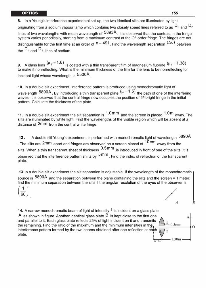
155 OPTICS
8. In a Young’s interference experimental set-up, the two identical slits are illuminated by light
originating from a sodium vapour lamp which contains two closely speed lines referred to as 1D and 2D lines of two wavelengths with mean wavelength of 5893Å . It is observed that the contrast in the fringe system varies periodically, starting from a maximum contrast at the Oth order fringe. The fringes are not distinguishable for the first time at an order of n 491= . Find the wavelength separation ( )∆λ between
the 1D and 2D lines of sodium.
9. A glass lens g( 1.6)µ = is coated with a thin transparent film of magnesium fluoride f( 1.38)µ =
to make it nonreflecting. What is the minimum thickness of the film for the lens to be nonreflecting for incident light whose wavelength is 5500Å .
10. In a double slit experiment, interference pattern is produced using monochromatic light of wavelength 5890Å . By introducing a thin transparent plate ( 1.5)µ = the path of one of the interfering waves, it is observed that the central fringe now occupies the position of 5th bright fringe in the initial pattern. Calculate the thickness of the plate.
11. In a double slit experiment the slit separation is 1.0mm and the screen is placed 1.0m away. The slits are illuminated by white light. Find the wavelengths of the visible region which will be absent at a distance of 2mm from the central white fringe.
12 . A double slit Young’s experiment is performed with monochromatic light of wavelength 5890Å
. The slits are 2mm apart and fringes are observed on a screen placed at 10cm away from the slits. When a thin transparent sheet of thickness 0.5mm is introduced in front of one of the slits, it is observed that the interference pattern shifts by 5mm . Find the index of refraction of the transparent plate.
13. In a double slit experiment the slit separation is adjustable. If the wavelength of the monochromatic source is 5890Å and the separation between the plane containing the slits and the screen = 1 meter; find the minimum separation between the slits if the angular resolution of the eyes of the observer is
o160
.
A B
14. A narrow monochromatic beam of light of intensity I is incident on a glass plate A as shown in figure. Another identical glass plate B is kept close to the first one and parallel to it. Each glass plate reflects 25% of light incident on it and transmits the remaining. Find the ratio of the maximum and the minimum intensities in the interference pattern formed by the two beams obtained after one reflection at each plate.
A
O0.5mm
1.30m
L1
L2
0.15m
S

156 OPTICS
15. In the given figure a thin convex lens of circular shape having focal
length 10cm is cut into two identical halves 1L and 2L by a plane through its diameter which are placed symmetrically about the central
axis SO with a gap of 0.5mm . A monochromatic source of wavelength 500nm and a screen are placed at 15cm and 130cm from the lens system.
(i) Find the distance OA , if A is the position of the third maximum in the interference pattern
(ii) What will happen to the fringe system if the gap between 1L and 2L is reduced, other conditions remaining the same.
KEY1. (i) 1.17 mm (ii) 0.156 cm2. = 5892 Å3. = 14.76 mm.4. x = 0.347m.
5.
2
2
dy ( 1)ab 1 / d4a
= µ − +
6. (2n 1) 0.14 m= + × µ
7. 3/48. =6Å9. 99.6 nm.
10. 45.89 10 cm−= ×
11. 4444Å and 5714Å
12. 1.2µ =
13. 2.025nm.
14. max minI / I
15. (i) 1 mm (ii) fringe width increases
SUBJECTIVE QUESTIONS
HINTS AND SOLUTIONS
1. (i) For constructive interference resulting in the formation of bright fringe, the distance nx for the nth
bright fringe from the central maximum is n
nDxd
λ=
Given n 3= , D 120cm= , 6500 Åλ =
106500 10 m−= × , d 2mm=
32 10 m−= ×

157 OPTICS
∴
2 10
n 3
3 120 10 6500 10x m2 10
− −
−
× × × ×=
×
1.17mm= .
(ii) For the coincidence of the two bright fringes, let nth bright fringe of 1λ coincides with th(n 1)+
bright fringe of 2λ , thus
1 2n(D ) D(n 1)
d dλ λ
= +
or,
1
2
n 1 6500 5n 5200 4
λ+= = =
λ
∴ n 4= ∴Required distance from the central maximum is
81
1
nD 4 120 6500 10x cmd 2 10
−
−
λ × × ×= =
×
0.156cm= .2. The distance through which the central fringe gets shifted by introducing the mica sheet is
x ( 1)tD / d= µ − … (i) where µ = refractive index of mica,
t = its thickness 61.964 10 m−= ×
D = separation between screen and the plane of the slits and d = slit separation In the second case, D is changed to 2D and the mica plate is removed, the fringe width
(2D)d
λβ =
... (ii) Equating (i) and (ii), we get
( 1)tD 2Dd d
µ − λ=
or,
( 1)t2
µ −λ =
6(1.6 1) 1.964 10 m2
−− × ×=
60.5892 10 m−= × 5892Å= .
3. If β be the separation between two consecutive bright bands, we have, the path difference
1 22(t t )− = λ
or, 2 tanβ θ = λ
∴
10
3
5893 10 mtan2 2 1.2 10
−
−
λ ×θ = =
β × ×
or, 42.46 10−θ = × radius
If t be the thickness of the foil,
t tans
= θ
or, ( )2 4t s tan 6 10 m (2.46 10 )− −= ⋅ θ = × ×
614.76 10 m−= ×
14.76 m= µ .

158 OPTICS
4. The condition for minimum contrast is given by
1 2
1n n2
λ = + λ
or,
1n(5895) n 58902
= +
Solving, we get n 589= . Thus fringes will be indistinguishable at the order n 589= . The required distance from the centre of the screen is
10
3
D 589 5895 10 1x n nd 10
−
−
λ × × ×= β = =
0.347m= .
5. Let the central fringe is shifted to P , where OP y= . For P to be the central maximum, optical path
from S to P through the slits 1S and 2S must be equal.
∴ 2 2 1 1(SS ) S P SS S Pµ + = +
or, 2 1 2( 1)SS (S P S P)µ − = −
1 2S S sin dtan= ⋅ θ = θ
or,
22 d y( 1) a d
2 b µ − + = ⋅
Simplifying, we get
2
2
dy ( 1)ab 1 / d4a
= µ − +
.6. For maximum intensity in the reflected beam, the condition of constructive interference
12 t cosr n2
µ = + λ must be satisfied. The thickness
1t n2 2 cosr
λ = + µ
2 2
1n2 2 sin i
λ = + µ −
2 2
1 0.60 mn2 2 (1.33) (0.788)
µ = + −
0.15 m(2n 1)1.071
µ= +
(2n 1) 0.14 m= + × µ .
Hence the required thickness will be (0.14,0.42,0.70,....) mµ .
7. For the slit 1S , the optical path introduced is 1 s 1( )t∆ = µ − µ
Similarly for slit 2S ,
2 s 2( )t∆ = µ − µ
∴ Net optical path introduced is
1 2 s 1 2( )(t t )∆ = ∆ − ∆ = µ − µ −
(1.4 1.3)(2 1) m 0.1 m= − − µ = µ
∴ The phase difference between the waves reaching the point equidistant from the two slits will be

159 OPTICS
0
2πφ = ×
λ optical path difference
6
10
2 0.1 1036000 10
−
−
π × × π= =
×
Hence the intensity at O is
1 2 1 2I I I 2 I I cos= + + φ
0 0 0 0I I 2I cos 3I
3π
= + + × =
But the intensity where the waves superpose in the same phase is
( ) ( )2 2
max 1 2 0 0I I I 2 I 4I= + = =
∴ The required ratio of intensities is
0
max 0
3II 3I 4I 4
= =.
8. The two spectral lines will produce their individual fringe pattern and their superposition results in the variation of contrast starting from the Oth order to a minimum contrast at the nth order where n 491= .
This happens when maximum of 1λ falls on the minimum of 2λ ,
i.e., 1 2
1n n2
λ = + λ ,
where, 1λ and 2λ are the component wave length with 1 2λ > λ . Given n 491= , we have
1 2
1491 4912
λ = + λ
or,
1
2
983982
λ=
λ
or,
1 2
1 2
19651
λ + λ=
λ − λ
or,
1 2 19652( ) 2
λ + λ=
∆λ
or, mean 1965
2λ
=∆λ
or, mean2 5893 2 6Å
1965 1965⋅ λ ×
∆λ = = ≈
Hence wavelength separation 6Å= .9. A glass lens is made nonreflecting by coating it with a thin film of a material whose refractive index
f gµ < µ. If the coating is a quarter-wave length thick, the difference in the path length between the

160 OPTICS
reflected rays is 2t / 2′= λ , where ′λ0
f
λ=
µ is the wavelength of light in the coating. Here both the reflected waves (i) and (ii) undergo a 180° phase shift, they are out of phase for a path difference of
/ 2′λ and interfere destructively, i.e., the waves are transmitted rather than reflected, making the lens surface nonreflecting.
Hence mint
4′λ
=
0
f4λ
=µ
105500 10 m4 1.38
−×=
×
999.6 10 m−= ×
99.6nm= .10. Displacement of the central fringe is given by
( 1)tDxd
µ −=
Given that this displacement is equal to five times the fringe width, i.e.,
D5 5dλ
β =
∴
( 1)tD 5Dd d
µ − λ=
or,
85 5 5890 10t cm( 1) (1.5 1)
−λ × ×= =
µ − −
45.89 10 cm−= × .
11. The wavelengths which satisfy the condition for destructive interference will remain absent at the given
position and correspond to the dark fringe. If nx be the distance from the central maximum where dark fringe exists, we have
nx (2n 1)
2β
= +,
where, n 0,1,2,....= and β is the fringe width
Ddλ =
∴ n
D 1 Dx (2n 1) n2d 2 d
λ λ = + = +
or, n
1x d / n D2
λ = ⋅ +
Given 3
nx 2mm 2 10 m−= = × ,
3d 1mm 1 10 m−= = ×
D 1.0m=
Putting n 1,2,3,4......=

161 OPTICS
40000Å,1333.3Å, 8000Å,5714.2Å,4444.4Å,3636.3Åλ = .
The absent components consist of 4444Å and 5714Å . 12. In absence of the thin plate, the path difference at the central fringe is zero, but its introduction in front of
one of the slits produces a path difference ( 1)t∆ = µ − where t is the thickness and µ is its refractive index. Since introducing a path difference of one wave length shifts the fringe system by one fringe-
width ( )= β , hence number of fringes shifted will be
( 1)tn ∆ µ −= =
λ λ and the corresponding distance
( 1)t D ( 1)tDx nd d
µ − λ µ −= β = ⋅ =
λ
Given 2t 0.5mm =5 10 cm,D 10cm−= × =
d 2mm 0.2cm,= = x 0.5cm=
∴
2( 1) 5 10 100.50.2
−µ − × × ×=
Solving we get
1.2µ = .
13. The observed can see the fringes distinctly if the angle subtended by the fringe width β at the eye
( )= θ be such that
o160
θ >
But Dβ
θ =(radian)
DdD d
λ λ= =
∴ min
1d 60 180
λ π= ×
or, min
60 180d λ × ×=
π
105890 10 60 180 (m)3.14
−× × ×=
2.025mm= .
14. Since each plate reflects 25%
14
= of the incident intensity, the transmitted wave will consist of 75%
34
= of the incident light, assuming no absorption by the this glass plates. The intensity of part (i)
and (ii) are shown in the figure as
I4 and
9 I64 respectively.
If 1a and 2a be the corresponding amplitudes, then

162 OPTICS
2
1 1
2 2
I aI a
=
or,
1 1
2 2
a I I / 4 4a I 9I / 64 3
= = =
or,
1 2
1 2
a a 7a a 1
+= −
or,
21 2
21 2
(a a ) 491(a a )
+=
−
or, max minI / I .
15. (i) The split parts 1L and 2L of the convex lens with a separation 1 2O O produces coherent sources
(real images of S ) 1S and 2S . The separation between 1S and 2S can be obtained from similar
triangle 1 2SO O and 1 2SS S .
1 2
1 2
O O uS S u v
=+
or, 1 2
0.5mm 15cmS S (15 30)cm
=+ [ v 30cm= from lens formula]
or, 1 2S S 1.5mm=
Now, the fringe width
Ddλ
β =; where
D = distance between coherent sources & screen
(130 30)cm 100cm= − =
9 7500nm 500 10 m 500 10 cm− −λ = = × = ×
and, d 1.5mm 0.15cm= =
∴
7100 500 10 1 cm0.15 30
−× ×β = =
∴1 1OA 3 3 cm cm
30 10= β = × =
= 1mm .
(ii) If the separation 1 2O O is reduced the distance between the coherent sources 1 2 1 2
u vd S S O Ou+ = =
is also reduced and accordingly the fringe width
Ddλ β =
increases. ADDITIONAL QUESTIONS1. A doubled slit apparatus is immersed in a liquid of refractive index 1.33. It has slit separation of
1 mm and distance between the plane of slits and screen is 1.33 m. The slits are illuminated by a parallel beam of light whose wavelength in air is 6300 Å .
(i) calculate the fringe width (ii) one of the slits of the apparatus is covered by a thin glass sheet of refractive index 1.53. Find the
smallest thickness of the sheet to bring the adjacent maximum on the axis.
x
y
D=1.0 m
d=1.0 mm
Screen
30º

163 OPTICS
2. A coherent parallel beam of microwaves of wavelength 0.5λ = mm falls on a Young’s double slit apparatus. The separation between the slits is 1.0 mm. The intensity of microwaves is measured on a screen placed parallel to the plane of the slits at a distance of 1.0 m from it as shown in the figure.
(a) If the incident beam falls normally on the double slit apparatus, find the y–coordinates of all the interference minima on the screen.
(b) If the incident beam makes an angle of 30° with the x–axis (as in the dotted arrows shown in figure), find the y–coordinates of the first minima on either side of the central maximum.
S
Y
O*
3. The Young’s double slit experiment is done in a medium of
refractive index 4/3. A light of 600 nm wavelength is falling on the slits having 0.45 mm separation. The lower slit S2 is covered by a thin glass sheet of thickness 10.4 mµ and refractive index 1.5. The interference pattern is observed on a screen placed 1.5 m away from the slits as shown.
(a) Find the location of central maximum (bright fringe with zero path difference) on the y-axis. (b) Find the light intensity at point O relative to the maximum fringe intensity. (c) Now if 600 nm light is replaced by white light of range 400 to 700 nm, find the wavelengths of the
light that form maxima exactly at point O. [All wavelengths in the are for the given medium of refractive index 4/3. Ignore dispersion]
4. In a Young’s double slit experiment, two wavelengths of 500 nm and 700 nm were used. What is the
minimum distance from the central maximum where their maxima coincide again? Take 3D / d 10= .
Symbols have their usual meanings.
5. A beam of light consisting of two wavelengths 6500 Å and 5200 Å is used to obtain interference fringes in a Young’s double slit experiment. (a) Find the distance of the third bright fringe on the screen from the central maxima for the wavelength 6500 Å. (b) What is the least distance from the central maxima where the bright fringes due to both the wavelengths coincide? The distance between the slits is 2 mm and the distance between the plane of the slits and screen is 120 cm.
6. In a modified Young’s double slit experiment, a monochromatic uniform and parallel beam of light of wavelength 6000 Å and intensity (10/p)W/m2 is incident normally on two circular apertures A and B of radii 0.001 m and 0.002 m respectively. A perfectly transparent film of thickness 2000 Å and refractive index 1.5 for wavelength 6000 Å is placed in front of aperture A. Calculate the power (in watts) received at the focal spot F of the lens. The lens is symmetrically placed with respect to the aperture. Assume that 10% of the power received by each aperture goes in the original direction and is bought to the focal spot.
KEY
1. (i) 0.63mmω = (ii) t 1.579 m= µ
2. (a) 0.26m± and 1.13m± (b) 1y 0.26m= and 2y 1.13m=
3. (a) y 4.33mm=
(b) max
3I I4
=

164 OPTICS (c) 400 to 700 nm are 650 nm and 433.33 nm
4. = 3.5 mm.
5. (a) b = 0.039 cm (b) y′ = 0.156 cm
6. 7 ´ 10–6 watt
HINTS AND SOLUTIONS
1. Given — m = 1.33, d = 1 mm, D = 1.33 m l = 6300 Å (i) Wavelength of light in the given liquid —
l¢ =
63001.33
λ=
µ Å » 4737 Å = 4737 × 10–10 m
\ Fringe width, w =
Dd′λ
w =
10
3
(4737 10 m)(1.33 m)(1 10 m)
−
−
××
= 6.3 × 10⁻⁴ m (ii) Let t be the thickness of the glass slab.
O
Path difference due to glass slab at center O.
Dx =
glass
liquid
ì1
ì
− t
=
1.53 11.33
− t
or Dx = 0.15 t
Now, for the intensity to be minimum at O, this path difference should be equal to 2′λ
\ Dx = 2′λ
or 0.15 t =
47372 Å
\ t = 15790 Å or t = 1.579 mm.2. Given l = 0.5 mm, d = 1.0 mm, D = 1m
(a) When the incident beam falls normally . Path difference between the two rays S2P and S1P is Dx = S2P – S1P » d sin q For minimum intensity,
d sin q = (2n – 1) 2λ
, n = 1, 2, 3, ….
or sin q =
( )2n 14− λ

165 OPTICS
=
(2n 1)0.52 1.0
−× =
2n 14−
As sin q £ 1 therefore
(2n 1)4−
£ 1 or n £ 2.5 So, n can be either 1 or 2
When n = 1, sin q1 =
14 or tan q1 =
115
n = 2, sin q2 =
34 or tan q2 =
37
\ y = D tan q = tan q (D = 1 m) So, the position of minima will be .
y1 = tan q1 =
115 m = 0.26 m
y2 = tan q2 =
37 m = 1.13 m
And as minima can be on either side of center O. Therefore there will be four minimas at positions ±0.26 m and +1.13 m on the screen. (b) When a = 30°, path difference between the rays before reaching S1 and S2 is
[In this case, net path difference Dx = Dx1 – Dx2]
Dx1 = d sin a = (1.0) sin 30° = 0.5 mm = l So, there is already a path difference of l between the rays. Position of central maximum. Central maximum is defined as a point where net path difference is zero.
So
Dx1 = Dx2 or d sin a = d sin q or q = a = 30°
or tan q =
13 =
0yD
\ y0 =
13 m (D = 1m)
y0 = 0.58 m At point P, Dx1 = Dx2 Above point P Dx2 > Dx1 and

166 OPTICS
Below point P Dx1 > Dx2 Now, let P1 and P2 be the minimas on either side of central maxima. Then, for P2
Dx2 – Dx1 = 2λ
or Dx2 = Dx1 + 2λ
= l + 2λ
=
32λ
or d sin q2 =
32λ
or sin q2 =
32d
λ
=
(3)(0.5)(2)(1.0) =
34
\ tan q2 =
37 =
2yD
or y2 =
37 m = 1.13 m
Similarly by for P1
Dx1 – Dx2 = 2λ
or Dx2 = Dx1 – 2λ
= l – 2λ
= 2λ
or d sin q1 = 2λ
or sin q1 = 2dλ
=
(0.5)(2)(1.0) =
14
\ tan q1 =
115 =
1yD
or y1 =
115 m = 0.26 m
Therefore, y-coordinates of the first minima on either side of the central maximum are y1 = 0.26 m and y2 = 1.13 m.
3. Given l = 600 nm = 6 × 10⁻⁷ m d = 0.45 mm = 0.45 × 10⁻³ m D = 1.5 m Thickness of glass sheet, t = 10.4 mm = 10.4 × 10⁻⁶ m
Refractive index of medium, mm =
43
And refractive index of glass sheet, mg = 1.5
(a) Let central maximum is obtained at a distance y below point O. Then Dx1 = S1P – S2P =
ydD
Path difference due to glass sheet
Dx2 =
g
m
1µ
− µ t Net path difference will be zero when Dx1= Dx2
or
ydD =
g
m
1µ
− µ t

167 OPTICS
\ y =
g
m
D1 td
µ − µ
Substituting the values, we have
y =
1.5 14 3
−
6
3
10.4 10 (1.5)0.45 10
−
−
××
y = 4.33 × 10⁻³ m or we can say y = 4.33 mm
(b) At O, Dx1 = 0 and Dx2 =
g
m
1 tµ
− µ \ Net path difference, Dx = Dx2
Corresponding phase difference, Df or simple f =
2πλ .Dx
Substituting the values, we have
f = 7
2 1.5 14 36 10−
π− ×
(10.4 × 10⁻⁶)
f =
133
π
Now, I(f) = Imax cos22φ
\ I = Imax cos2
136
π
I =
34 Imax
(c) At O . path difference is Dx = Dx2 =
g
m
1µ
− µ t For maximum intensity at O Dx = nl (Here n = 1, 2, 3, …)
\ l =
x x x, ,1 2 3
∆ ∆ ∆
… and so on
Dx =
1.5 14 3
−
(10.4 × 10⁻⁶ m)
=
1.5 14 3
−
(10.4 × 10³ nm) \ Maximum intensity will be corresponding to
l = 13000 nm,
13002 nm,
13003 m,
13004 nm ….
= 1300 nm, 650nm, 433.33 nm, 325 nm nm …. The wavelengths in the range 400 to 700 nm are 650 nm and 433.33 nm.4. Let n1 bright fringe corresponding to wavelength l1 = 500 nm coincides with n2 bright fringe
corresponding to wavelength l2 = 700 nm.
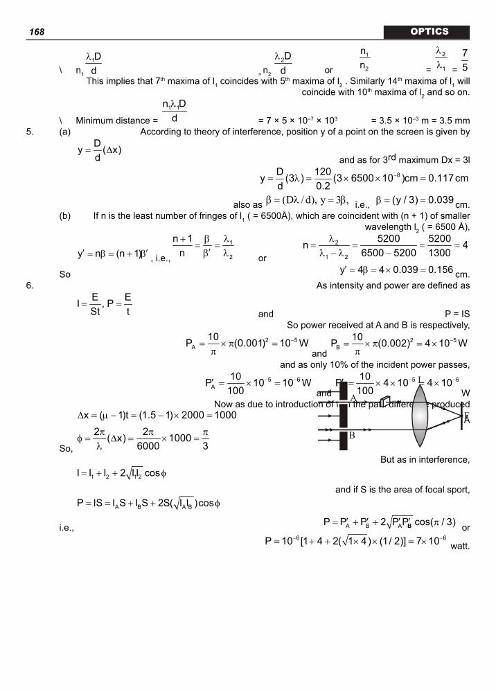
168 OPTICS
\ n1
1Dd
λ
= n2
2Dd
λ
or
1
2
nn =
2
1
λλ =
75
This implies that 7th maxima of l1 coincides with 5th maxima of l2 . Similarly 14th maxima of l1 will coincide with 10th maxima of l2 and so on.
\ Minimum distance = 1 1n Ddλ
= 7 × 5 × 10–7 × 103 = 3.5 × 10⁻³ m = 3.5 mm5. (a) According to theory of interference, position y of a point on the screen is given by
Dy ( x)d
= ∆ and as for 3rd maximum Dx = 3l
8D 120y (3 ) (3 6500 10 )cm 0.117cm
d 0.2−= λ = × × =
also as (D / d), y 3 ,β = λ = β i.e., (y / 3) 0.039β = = cm. (b) If n is the least number of fringes of l1 ( = 6500Å), which are coincident with (n + 1) of smaller
wavelength l2 ( = 6500 Å),
y n (n 1)′ ′= β = + β , i.e.,
1
2
n 1n
λ+ β= =
′β λ or
2
1 2
5200 5200n 46500 5200 1300
λ= = = =
λ − λ −
So y 4 4 0.039 0.156′ = β = × = cm.6. As intensity and power are defined as
E EI , PSt t
= = and P = IS
So power received at A and B is respectively,
2 5
A10P (0.001) 10 W−= × π =π and
2 5B
10P (0.002) 4 10 W−= × π = ×π
and as only 10% of the incident power passes,
5 6
A10P 10 10 W
100− −′ = × =
and 5 6
B10P 4 10 4 10
100− −′ = × × = ×
W Now as due to introduction of film the path difference produced
x ( 1)t (1.5 1) 2000 1000∆ = µ − = − × = Å
So,
2 2( x) 10006000 3
π π πφ = ∆ = × =
λ
A
B
L
F
But as in interference,
1 2 1 2I I I 2 I I cos= + + φ and if S is the area of focal sport,
A B A BP IS I S I S 2S( I I )cos= = + + φ
i.e., A B AP P P 2 P P cos( / 3)′ ′ ′ ′= + + πB or 6 6P 10 [1 4 2( 1 4) (1/ 2)] 7 10− −= + + × × = × watt.

169 OPTICS

170 OPTICS

171 OPTICS

172 OPTICS

173 OPTICS

174 OPTICS

175 OPTICS

176 OPTICS

177 OPTICS

178 OPTICS