rankine cycle sum
TRANSCRIPT
8/11/2019 Rankine Cycle Sum
http://slidepdf.com/reader/full/rankine-cycle-sum 1/76
Thermodynamics I
Spring 1432/1433H (2011/2012H)Saturday, Wednesday 8:00am -
10:00am & Monday 8:00am - 9:00amMEP 261 Class ZA
Dr. Walid A. AissaAssociate Professor, Mech. Engg. Dept.
Faculty of Engineering at Rabigh, KAU, KSA
Chapter #10
December XX, 2011
8/11/2019 Rankine Cycle Sum
http://slidepdf.com/reader/full/rankine-cycle-sum 2/76
Announcements:
Dr. Walid’s e-mail and Office Hours walid [email protected]
Office hours for Thermo 01 will be every
Sunday and Tuesday from 9:00 – 12:00 am
in Dr. Walid’ office (Room 5-213).Text book:
Thermodynamics An Engineering Approach Yunus A. Cengel & Michael A. Boles7th Edition, McGraw-Hill Companies,
ISBN-978-0-07-352932-5, 2008

8/11/2019 Rankine Cycle Sum
http://slidepdf.com/reader/full/rankine-cycle-sum 3/76
Chapter 10
VAPOR AND COMBINED POWERCYCLES
8/11/2019 Rankine Cycle Sum
http://slidepdf.com/reader/full/rankine-cycle-sum 4/76
Objectives of CH10: To
• Analyze vapor power cycles in which theworking fluid is alternately vaporized andcondensed .
• Analyze power generation coupled withprocess heating called cogeneration .
• Investigate ways to modify the basicRankine vapor power cycle to increase
the cycle thermal efficiency .• Analyze the reheat and regenerative
vapor power cycles .

8/11/2019 Rankine Cycle Sum
http://slidepdf.com/reader/full/rankine-cycle-sum 5/76
• Analyze power cycles that consist oftwo separate cycles known ascombined cycles and binary cycles
8/11/2019 Rankine Cycle Sum
http://slidepdf.com/reader/full/rankine-cycle-sum 6/76
Chapter 10
VAPOR AND COMBINED POWER CYCLES
10–1 ■ THE CARNOT VAPOR CYCLE
We have mentioned repeatedly that the Carnot cycle
is the most efficient cycle operating between two
spec e temperature m ts. us t s natura to ooat the Carnot cycle first as a prospective ideal cycle
for vapor power plants.
8/11/2019 Rankine Cycle Sum
http://slidepdf.com/reader/full/rankine-cycle-sum 7/76
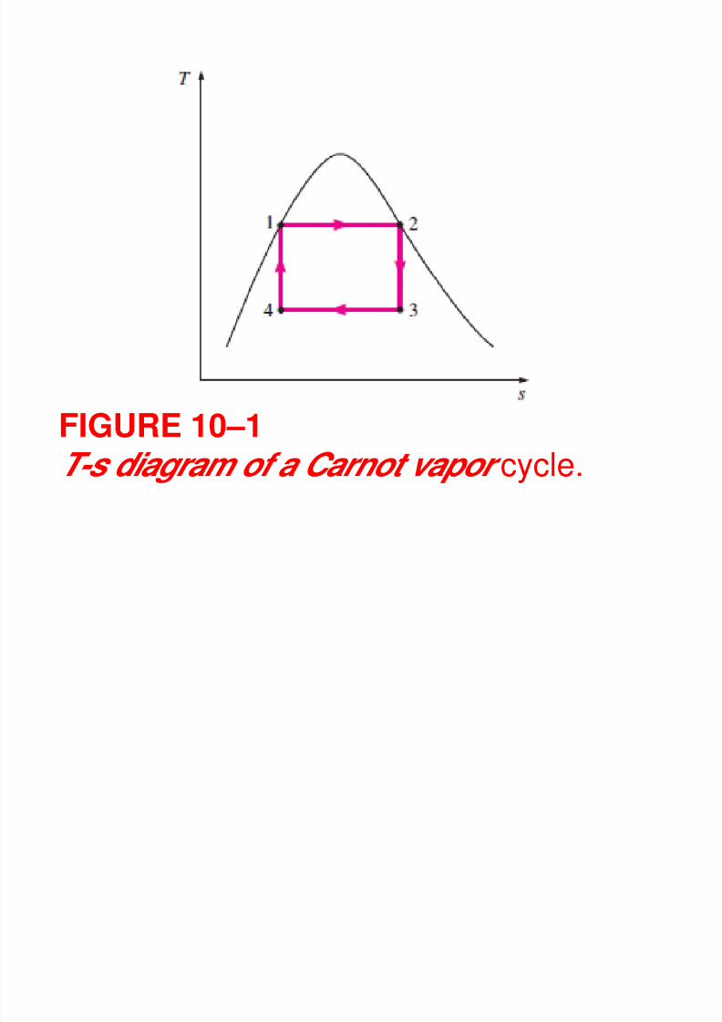
FIGURE 10–1T-s diagram of a Carnot vapor cycle.
8/11/2019 Rankine Cycle Sum
http://slidepdf.com/reader/full/rankine-cycle-sum 8/76
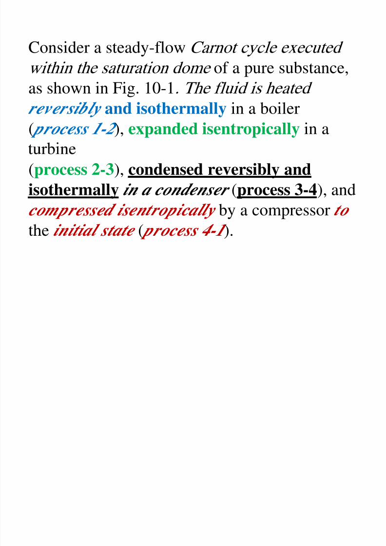
Consider a steady-flow Carnot cycle executedwithin the saturation dome of a pure substance,
as shown in Fig. 10-1. The fluid is heated
reversibly and isothermally in a boiler( process 1-2 ), expanded isentropically in a
(process 2-3), condensed reversibly and
isothermally in a condenser (process 3-4), and
compressed isentropically by a compressor to the initial state ( process 4-1 ).
8/11/2019 Rankine Cycle Sum
http://slidepdf.com/reader/full/rankine-cycle-sum 9/76
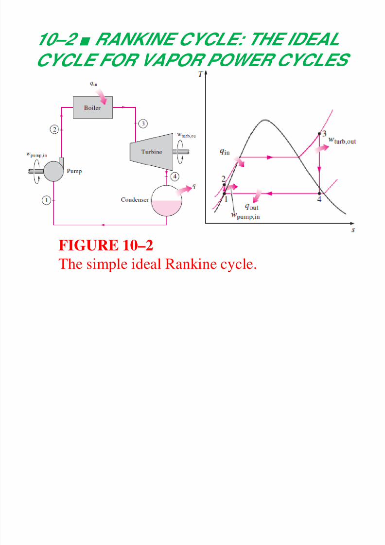
10–2 ■ RANKINE CYCLE: THE IDEALCYCLE FOR VAPOR POWER CYCLES
FIGURE 10–2
The simple ideal Rankine cycle.
8/11/2019 Rankine Cycle Sum
http://slidepdf.com/reader/full/rankine-cycle-sum 10/76
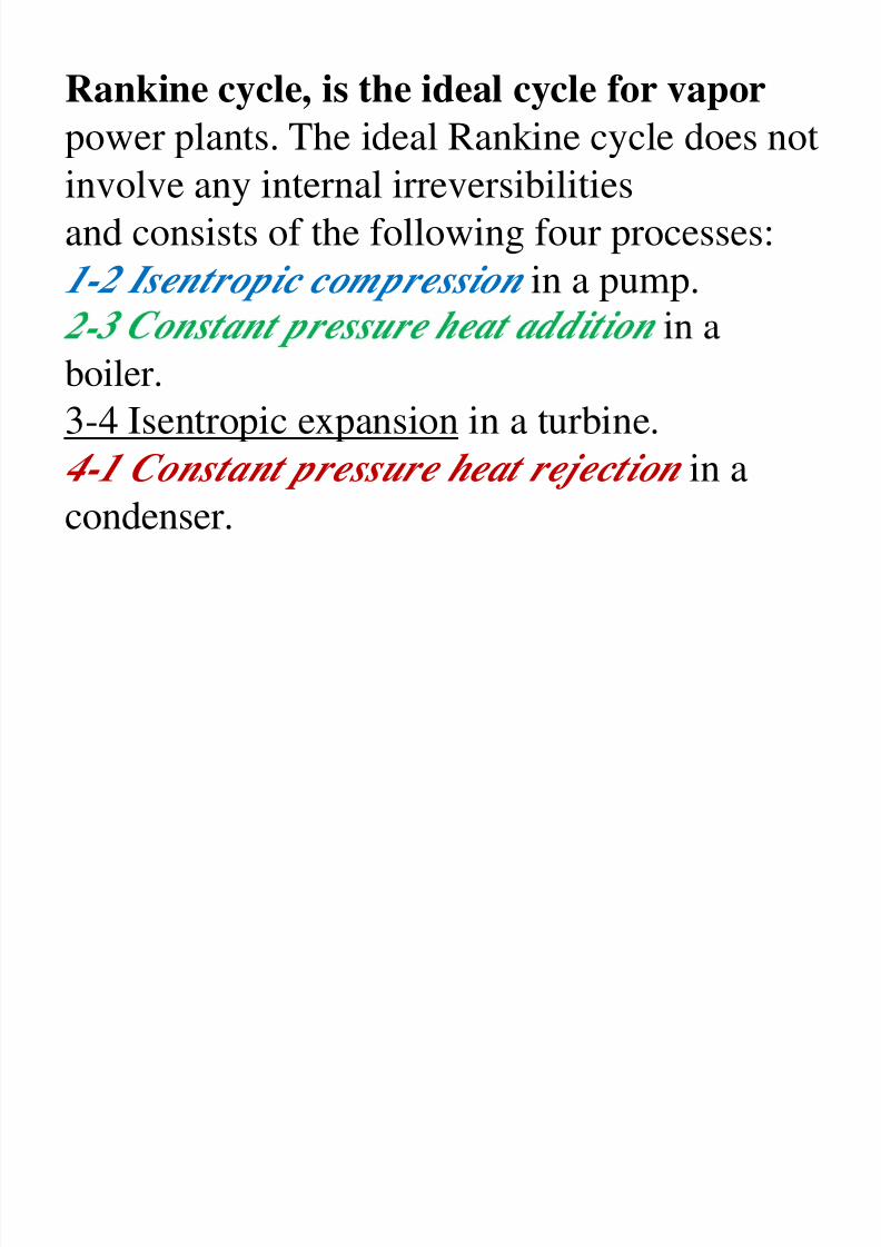
Rankine cycle, is the ideal cycle for vapor
power plants. The ideal Rankine cycle does not
involve any internal irreversibilities
and consists of the following four processes:1-2 Isentropic compression in a pump.
-
boiler.
3-4 Isentropic expansion in a turbine.
4-1 Constant pressure heat rejection in acondenser.
8/11/2019 Rankine Cycle Sum
http://slidepdf.com/reader/full/rankine-cycle-sum 11/76
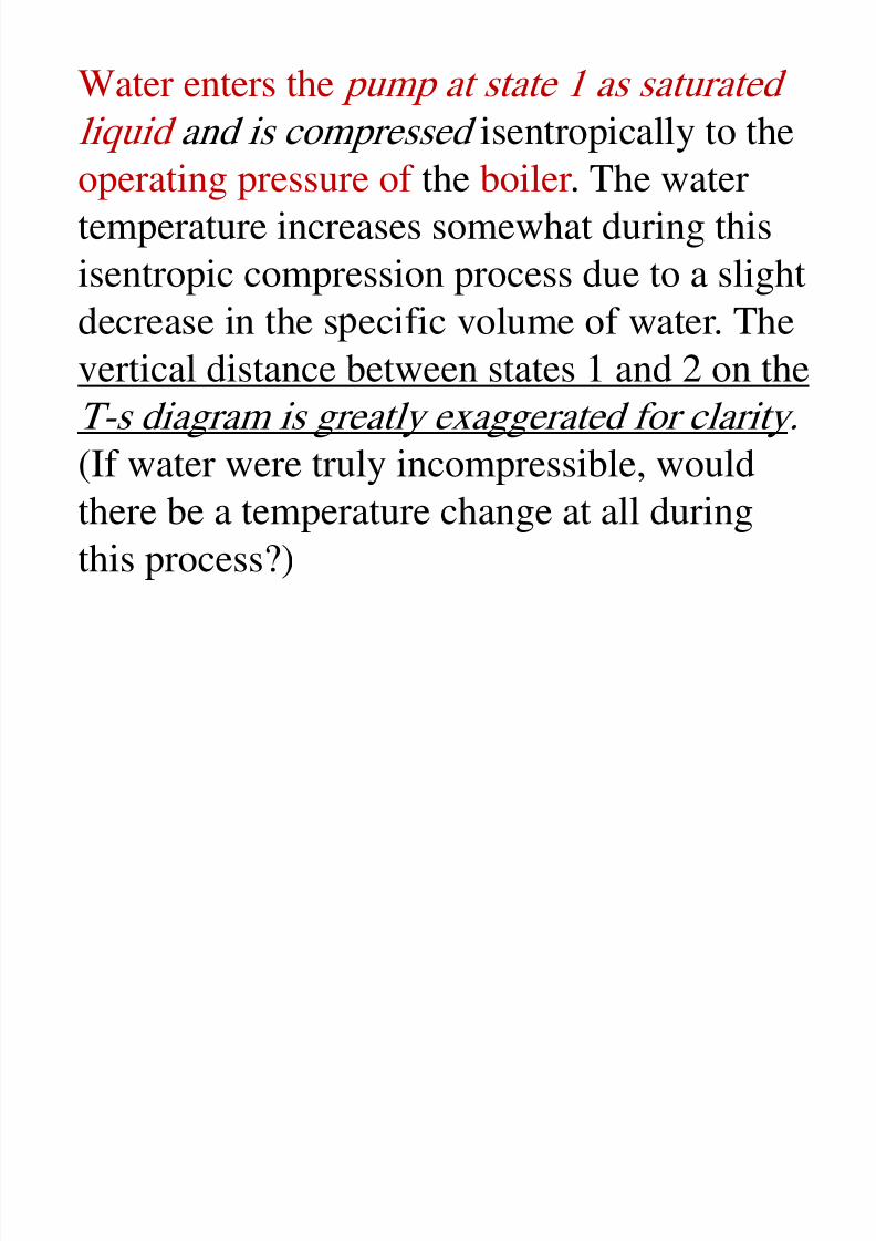
Water enters the pump at state 1 as saturated
liquid and is compressed isentropically to theoperating pressure of the boiler. The water
temperature increases somewhat during thisisentropic compression process due to a slight
decrease in the s ecific volume of water. The
vertical distance between states 1 and 2 on theT-s diagram is greatly exaggerated for clarity.
(If water were truly incompressible, wouldthere be a temperature change at all during
this process?)
8/11/2019 Rankine Cycle Sum
http://slidepdf.com/reader/full/rankine-cycle-sum 12/76
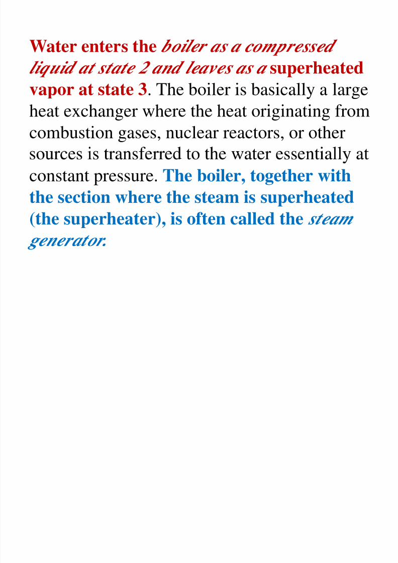
Water enters the boiler as a compressedliquid at state 2 and leaves as a superheated
vapor at state 3. The boiler is basically a large
heat exchanger where the heat originating fromcombustion gases, nuclear reactors, or other
constant pressure. The boiler, together with
the section where the steam is superheated
(the superheater), is often called the steam generator.
8/11/2019 Rankine Cycle Sum
http://slidepdf.com/reader/full/rankine-cycle-sum 13/76
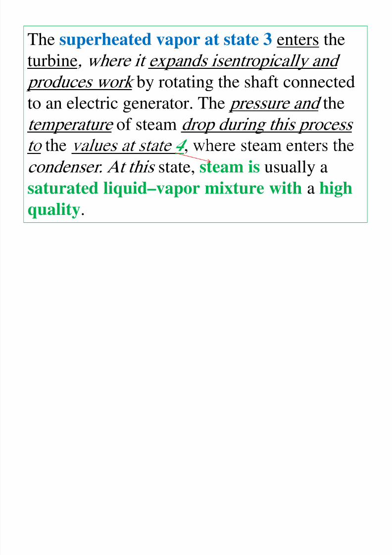
The superheated vapor at state 3 enters the
turbine, where it expands isentropically and
produces work by rotating the shaft connected
to an electric generator. The pressure and thetemperature of steam drop during this process
condenser. At this state, steam is usually a
saturated liquid–vapor mixture with a high
quality.
8/11/2019 Rankine Cycle Sum
http://slidepdf.com/reader/full/rankine-cycle-sum 14/76
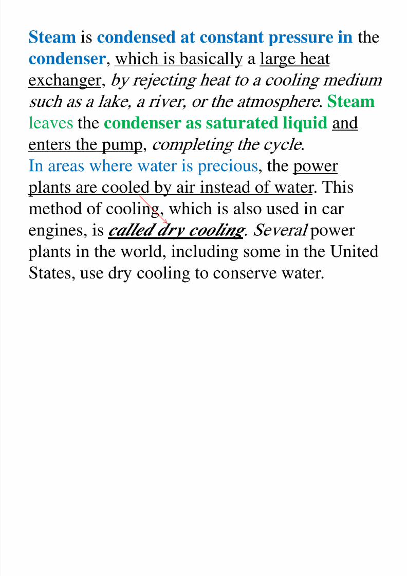
Steam is condensed at constant pressure in the
condenser, which is basically a large heatexchanger, by rejecting heat to a cooling medium
such as a lake, a river, or the atmosphere . Steam
leaves the condenser as saturated liquid and
enters the pump, completing the cycle .
In areas where water is precious, the powerplants are cooled by air instead of water. This
method of cooling, which is also used in car
engines, is called dry cooling . Several power
plants in the world, including some in the United
States, use dry cooling to conserve water.
8/11/2019 Rankine Cycle Sum
http://slidepdf.com/reader/full/rankine-cycle-sum 15/76
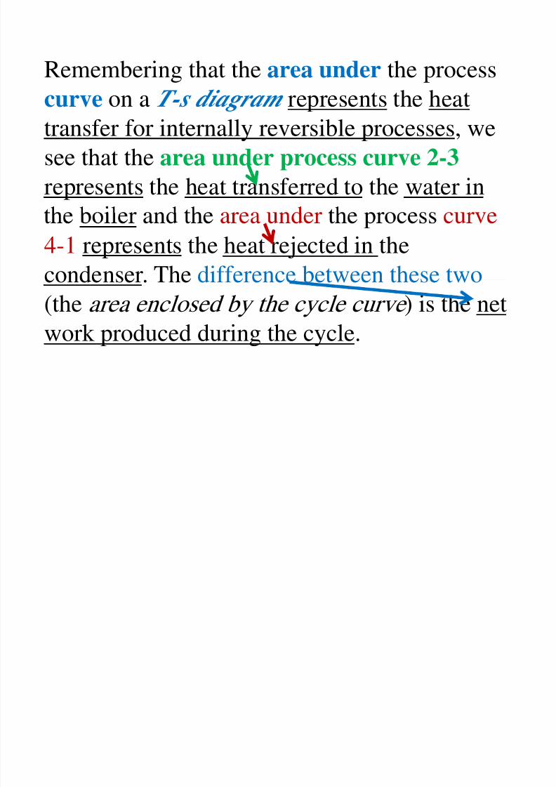
Remembering that the area under the processcurve on a T-s diagram represents the heat
transfer for internally reversible processes, we
see that the area under process curve 2-3represents the heat transferred to the water in
4-1 represents the heat rejected in the
condenser. The difference between these two
(the area enclosed by the cycle curve ) is the network produced during the cycle.
8/11/2019 Rankine Cycle Sum
http://slidepdf.com/reader/full/rankine-cycle-sum 16/76
Energy Analysis of the Ideal Rankine Cycle
All four components associated with the
Rankine cycle (the pump, boiler, turbine, and
condenser) are steady-flow devices, and thus allfour processes that make up the Rankine cycle
- .
The kinetic and potential energy changes of
the steam are usually small relative to the work and heat transfer terms and are therefore usually
neglected .
8/11/2019 Rankine Cycle Sum
http://slidepdf.com/reader/full/rankine-cycle-sum 17/76
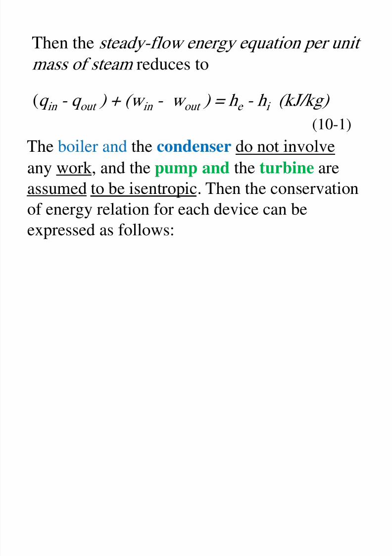
Then the steady-flow energy equation per unit
mass of steam reduces to
(q in - q out ) + (w in - w out ) = h e - h i (kJ/kg)
(10-1)
any work, and the pump and the turbine are
assumed to be isentropic. Then the conservation
of energy relation for each device can beexpressed as follows:
8/11/2019 Rankine Cycle Sum
http://slidepdf.com/reader/full/rankine-cycle-sum 18/76
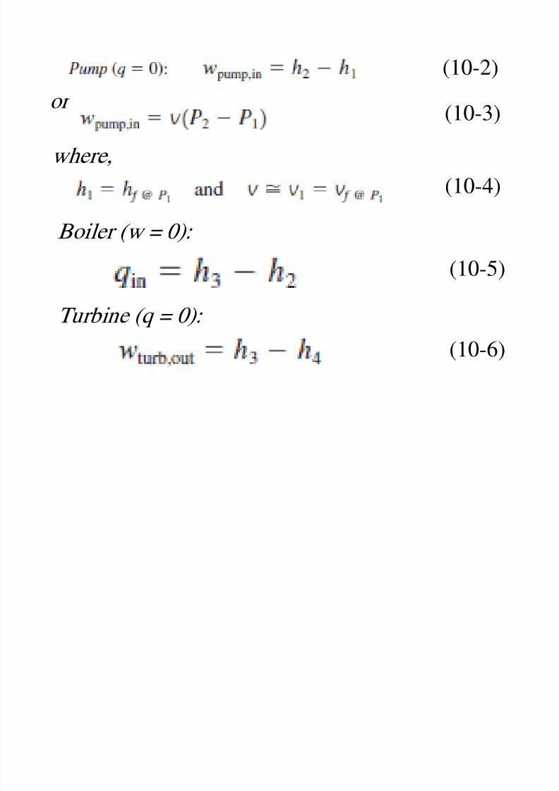
(10-2)or
(10-3)
where,(10-4)
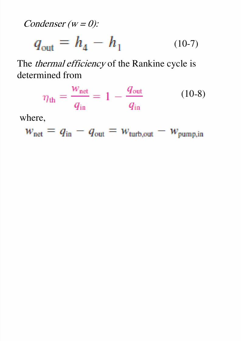
Boiler (w = 0):
(10-5)
Turbine (q = 0):
(10-6)
8/11/2019 Rankine Cycle Sum
http://slidepdf.com/reader/full/rankine-cycle-sum 19/76
8/11/2019 Rankine Cycle Sum
http://slidepdf.com/reader/full/rankine-cycle-sum 20/76
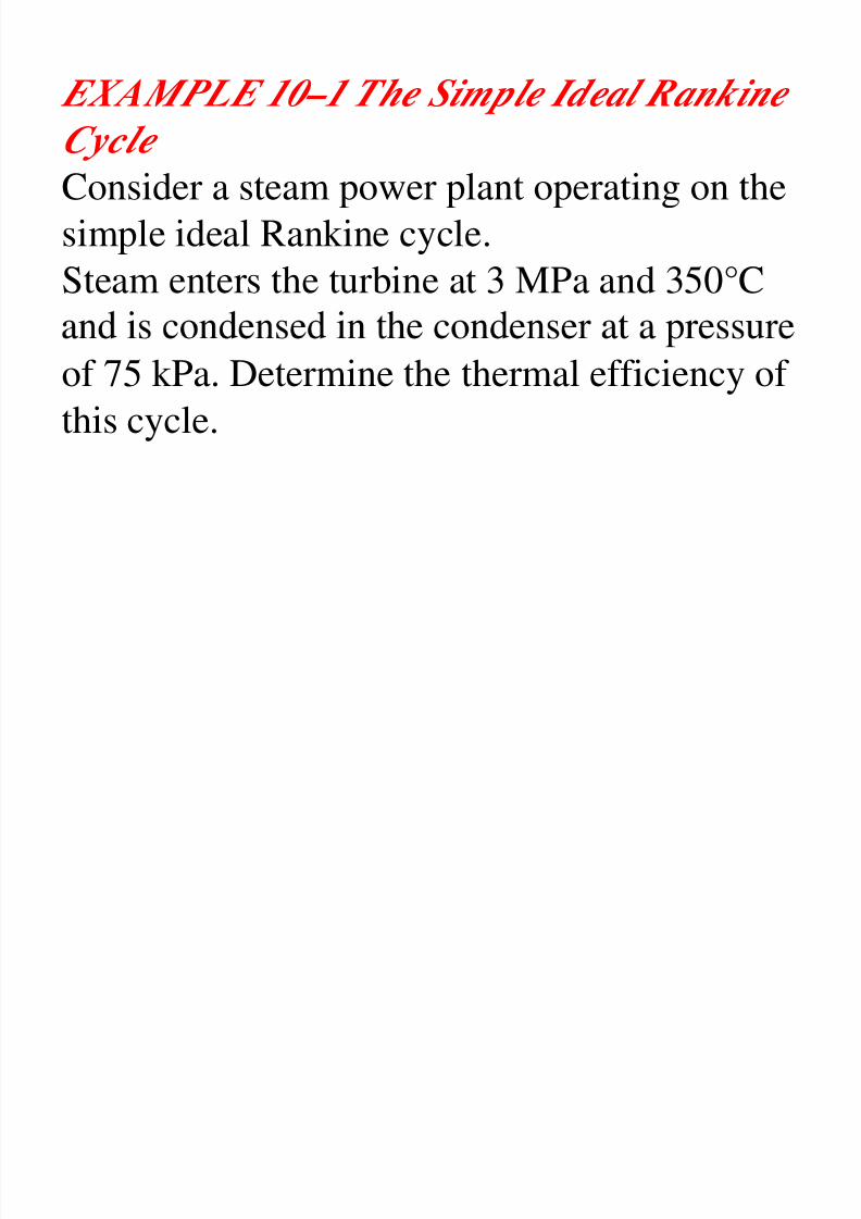
EXAMPLE 10–1 The Simple Ideal Rankine
Cycle
Consider a steam power plant operating on the
simple ideal Rankine cycle.Steam enters the turbine at 3 MPa and 350°C
of 75 kPa. Determine the thermal efficiency of
this cycle.
8/11/2019 Rankine Cycle Sum
http://slidepdf.com/reader/full/rankine-cycle-sum 21/76
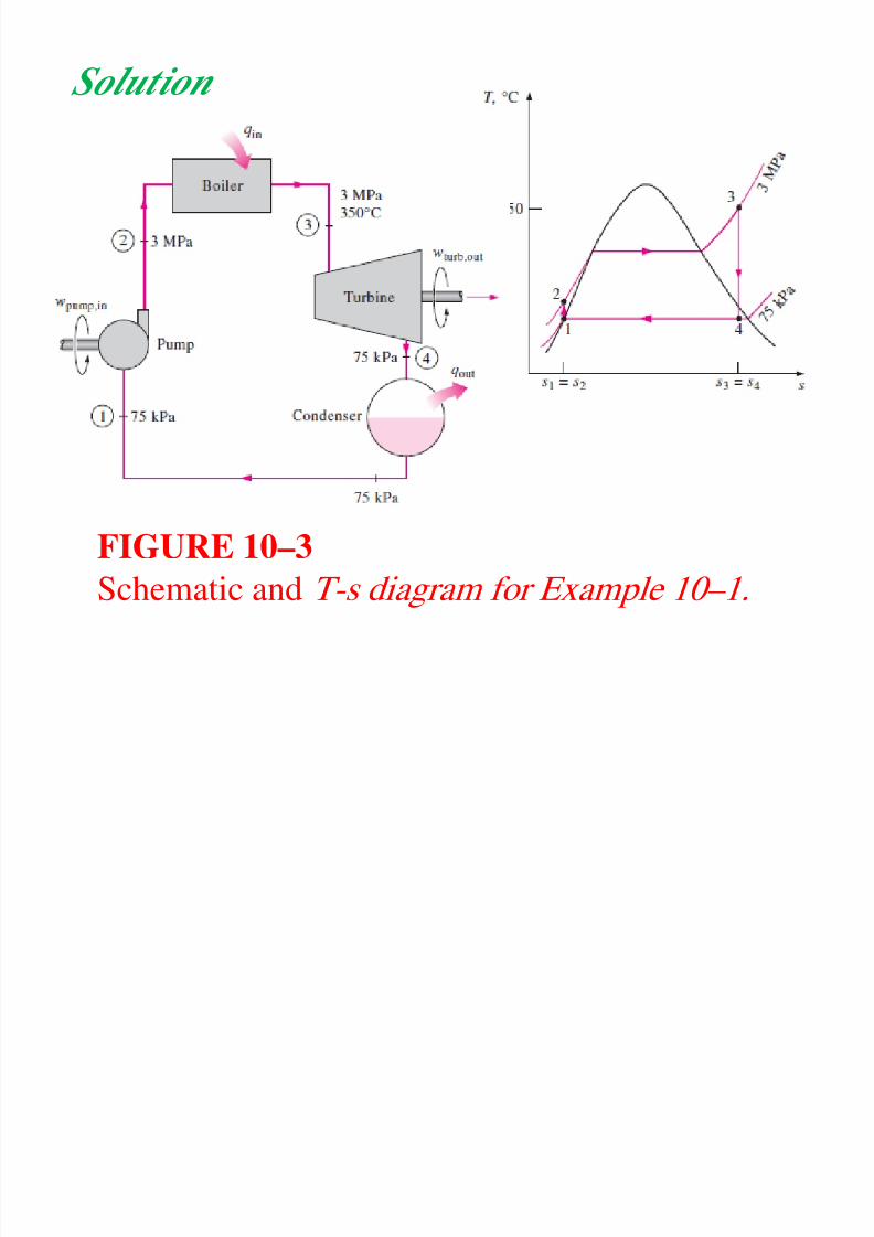
Solution
FIGURE 10–3
Schematic and T-s diagram for Example 10–1.
8/11/2019 Rankine Cycle Sum
http://slidepdf.com/reader/full/rankine-cycle-sum 22/76
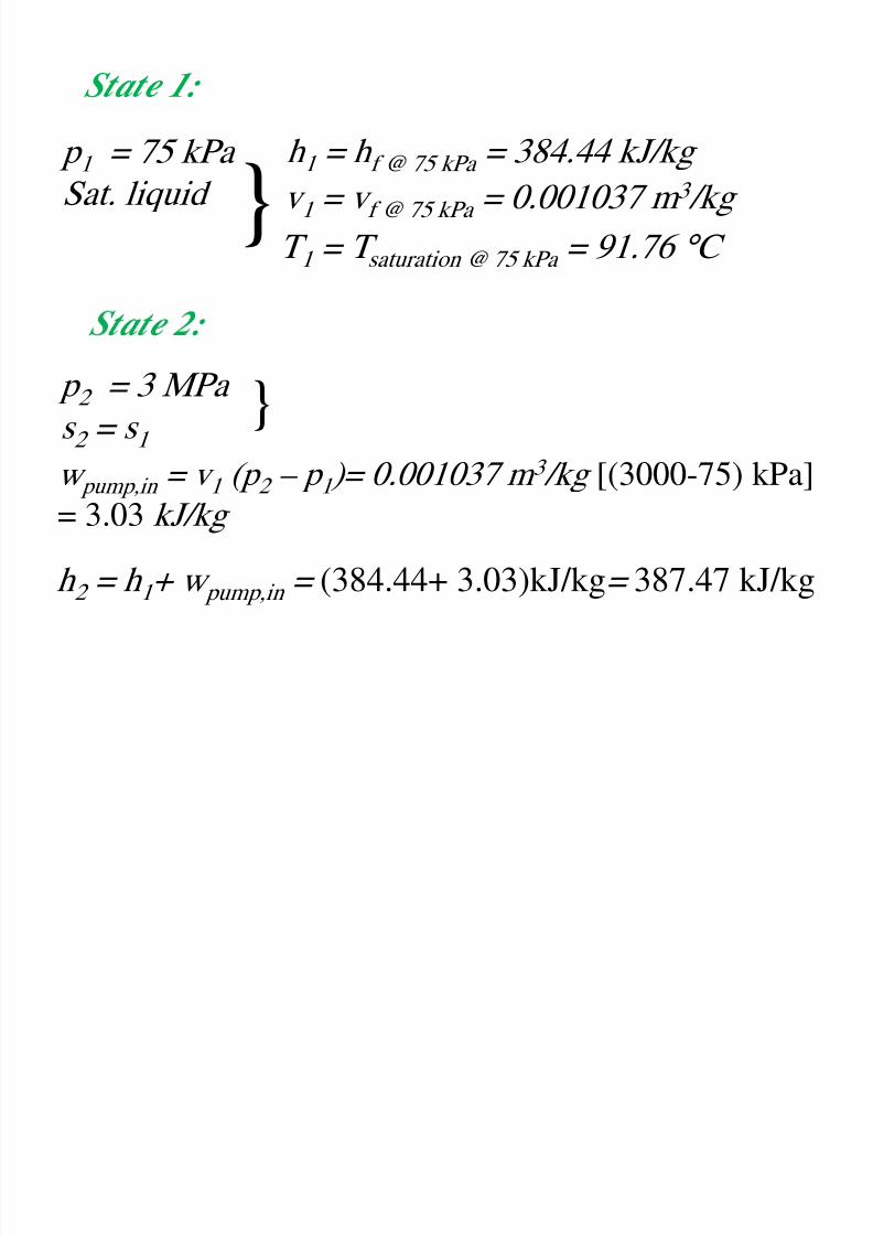
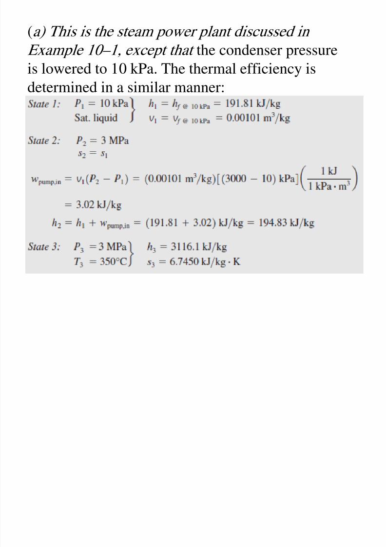
State 1:
p 1 = 75 kPa
Sat. liquid
}
h 1 = h f @ 75 kPa = 384.44 kJ/kg
v 1 = v f @ 75 kPa = 0.001037 m 3 /kg
T 1 = T saturation @ 75 kPa = 91.76 ° C
p 2 = 3 MPa
s 2 = s 1
w pump,in = v 1 (p 2 – p 1 )= 0.001037 m 3 /kg [(3000-75) kPa]= 3.03 kJ/kg
h 2 = h 1 + w pump,in = (384.44+ 3.03)kJ/kg= 387.47 kJ/kg
}
8/11/2019 Rankine Cycle Sum
http://slidepdf.com/reader/full/rankine-cycle-sum 23/76
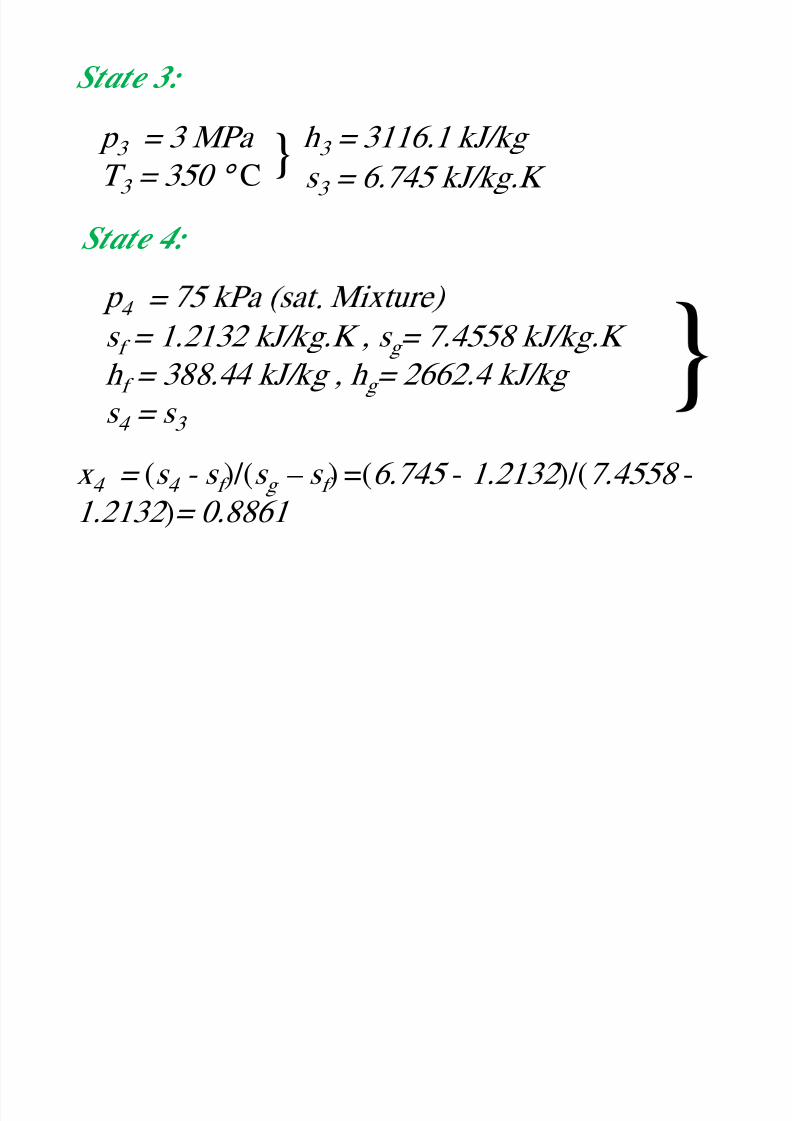
State 3:
p 3 = 3 MPa
T 3 = 350 ° C} h 3 = 3116.1 kJ/kg
s 3 = 6.745 kJ/kg.K
State 4:
= .
s f = 1.2132 kJ/kg.K , s g = 7.4558 kJ/kg.K
h f = 388.44 kJ/kg , h g = 2662.4 kJ/kg
s 4
= s 3
x 4 = (s 4 - s f )/(s g – s f ) =(6.745 - 1.2132 )/(7.4558 -
1.2132 )= 0.8861
8/11/2019 Rankine Cycle Sum
http://slidepdf.com/reader/full/rankine-cycle-sum 24/76
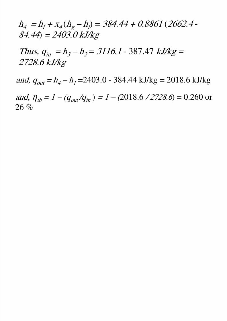
h 4 = h f + x 4 (h g – h f ) = 384.44 + 0.8861 (2662.4 -
84.44 ) = 2403.0 kJ/kg
Thus, q in = h 3 – h 2 = 3116.1 - 387.47 kJ/kg =
2728.6 kJ/kg
and, q out = h 4 – h 1 =2403.0 - 384.44 kJ/kg = 2018.6 kJ/kg
and, η th = 1 – (q out /q in ) = 1 – ( 2018.6 / 2728.6 ) = 0.260 or
26 %
8/11/2019 Rankine Cycle Sum
http://slidepdf.com/reader/full/rankine-cycle-sum 25/76
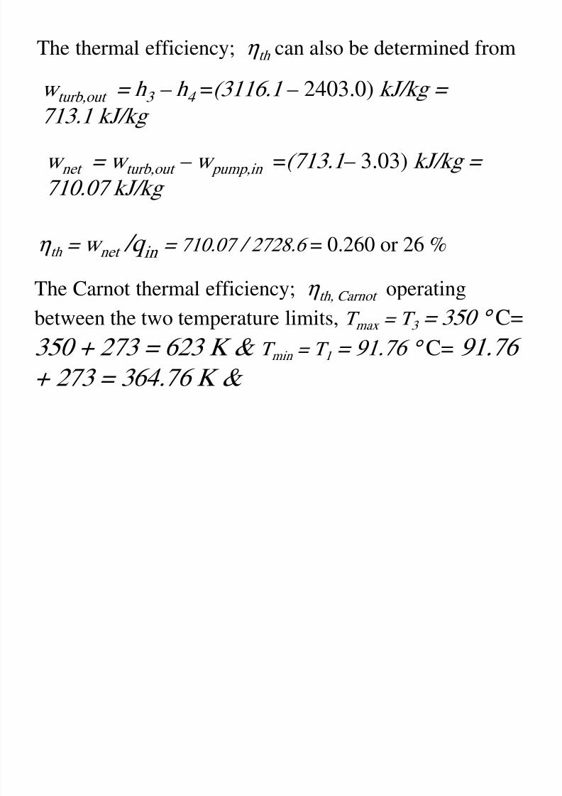
The thermal efficiency; η th can also be determined from
w turb,out = h 3 – h 4 =(3116.1 – 2403.0) kJ/kg =
713.1 kJ/kg
w net = w turb,out – w pump,in =(713.1 – 3.03) kJ/kg =710.07 kJ/kg
η th = w net /q in = 710.07 / 2728.6 = 0.260 or 26 %
The Carnot thermal efficiency; η th, Carnot operating
between the two temperature limits, T max = T 3 = 350 ° C=
350 + 273 = 623 K & T min = T 1 = 91.76 ° C= 91.76
+ 273 = 364.76 K &
8/11/2019 Rankine Cycle Sum
http://slidepdf.com/reader/full/rankine-cycle-sum 26/76
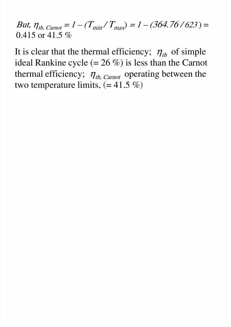
It is clear that the thermal efficiency; η th of simple
ideal Rankine cycle (= 26 %) is less than the Carnotthermal efficiency; η th, Carnot operating between the
two tem erature limits, = 41.5 %
But, η th, Carnot = 1 – ( T min / T max ) = 1 – ( 364.76 / 623 ) =
0.415 or 41.5 %
8/11/2019 Rankine Cycle Sum
http://slidepdf.com/reader/full/rankine-cycle-sum 27/76
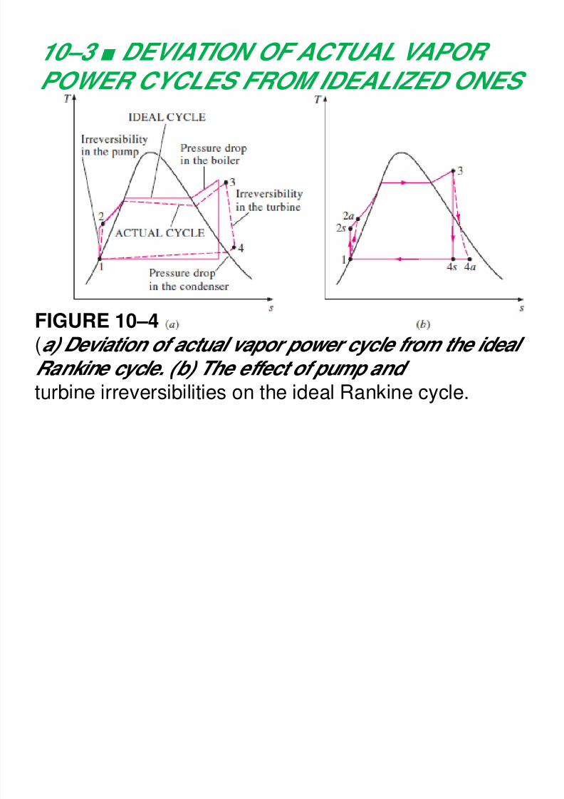
10–3 ■ DEVIATION OF ACTUAL VAPOR
POWER CYCLES FROM IDEALIZED ONES
FIGURE 10–4(a) Deviation of actual vapor power cycle from the idealRankine cycle. (b) The effect of pump and
turbine irreversibilities on the ideal Rankine cycle.
8/11/2019 Rankine Cycle Sum
http://slidepdf.com/reader/full/rankine-cycle-sum 28/76
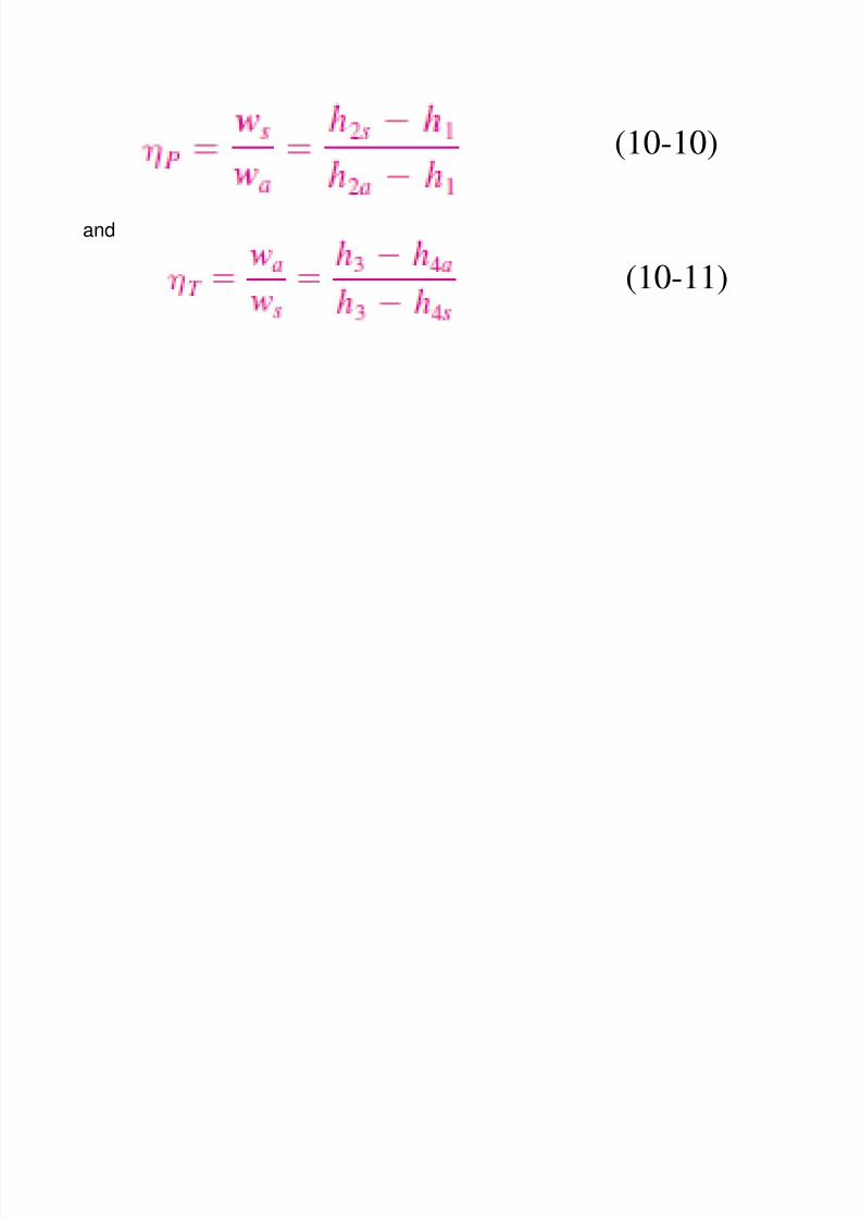
and
(10-10)
(10-11)
8/11/2019 Rankine Cycle Sum
http://slidepdf.com/reader/full/rankine-cycle-sum 29/76
EXAMPLE 10–2 An Actual Steam Power
Cycle
A steam power plant operates on the cycle shown
in Fig. 10–5. If the isentropic efficiency of theturbine is 87 percent and the isentropic efficiency
of the um is 85 ercent determine a the
thermal efficiency of the cycle and (b) the netpower output of the plant for a mass flow rate of
15 kg/s.
8/11/2019 Rankine Cycle Sum
http://slidepdf.com/reader/full/rankine-cycle-sum 30/76
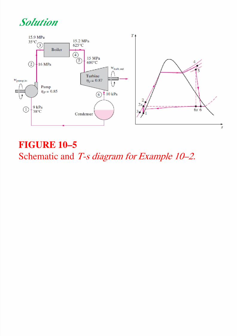
Solution
FIGURE 10–5
Schematic and T-s diagram for Example 10–2.

8/11/2019 Rankine Cycle Sum
http://slidepdf.com/reader/full/rankine-cycle-sum 31/76
Solution:
A steam power cycle with specified turbine and
pump efficiencies is considered. The thermal
efficiency and the net power output are to be
determined.
Assumptions : 1) Steady operating conditions exist.
K inetic and potential energy changes arenegligible.
8/11/2019 Rankine Cycle Sum
http://slidepdf.com/reader/full/rankine-cycle-sum 32/76
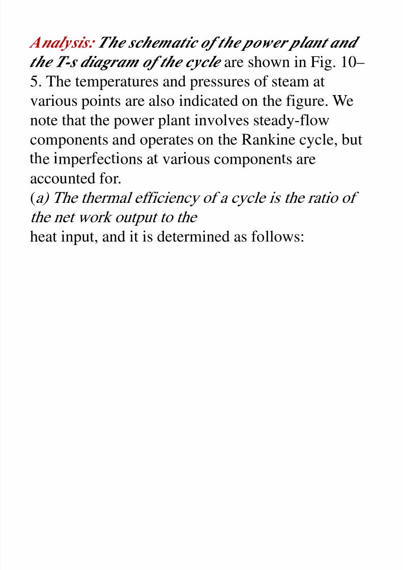
Analysis: The schematic of the power plant and
the T-s diagram of the cycle are shown in Fig. 10–5. The temperatures and pressures of steam at
various points are also indicated on the figure. We
note that the power plant involves steady-flow
components and operates on the Rankine cycle, but
e mper ec ons a var ous componen s areaccounted for.
(a) The thermal efficiency of a cycle is the ratio of
the net work output to the heat input, and it is determined as follows:
8/11/2019 Rankine Cycle Sum
http://slidepdf.com/reader/full/rankine-cycle-sum 33/76
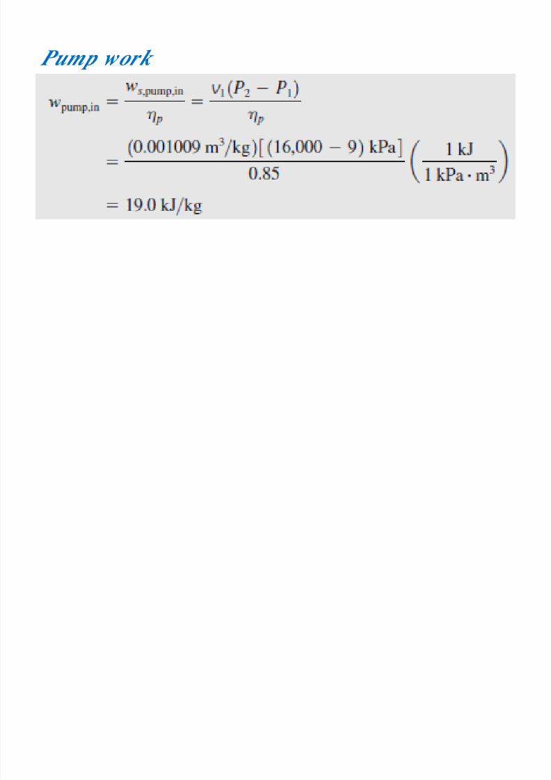
Pump work
input:
8/11/2019 Rankine Cycle Sum
http://slidepdf.com/reader/full/rankine-cycle-sum 34/76
8/11/2019 Rankine Cycle Sum
http://slidepdf.com/reader/full/rankine-cycle-sum 35/76
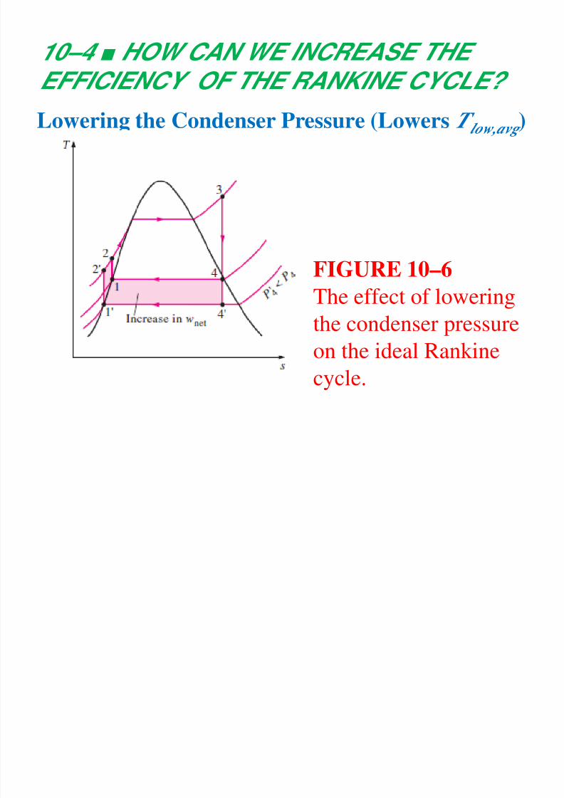
10–4 ■ HOW CAN WE INCREASE THE
EFFICIENCY OF THE RANKINE CYCLE?Lowering the Condenser Pressure (Lowers T low,avg )
FIGURE 10–6
The effect of lowering
the condenser pressure
on the ideal Rankine
cycle.
8/11/2019 Rankine Cycle Sum
http://slidepdf.com/reader/full/rankine-cycle-sum 36/76
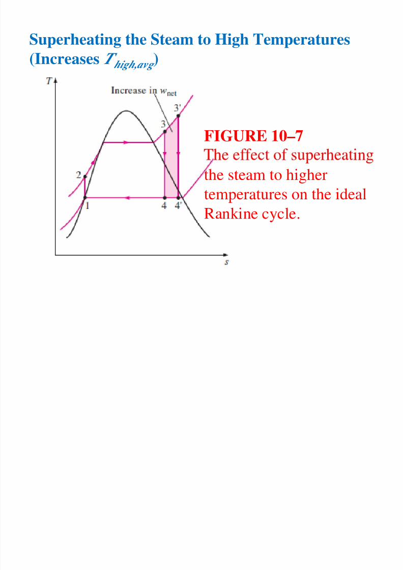
Superheating the Steam to High Temperatures
(Increases T high,avg )
FIGURE 10–7
the steam to higher
temperatures on the ideal
Rankine cycle.
8/11/2019 Rankine Cycle Sum
http://slidepdf.com/reader/full/rankine-cycle-sum 37/76
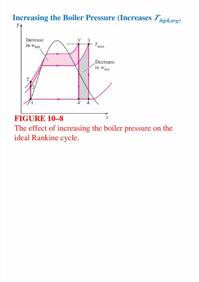
Increasing the Boiler Pressure (Increases T high,avg)
FIGURE 10–8
The effect of increasing the boiler pressure on the
ideal Rankine cycle.
8/11/2019 Rankine Cycle Sum
http://slidepdf.com/reader/full/rankine-cycle-sum 38/76
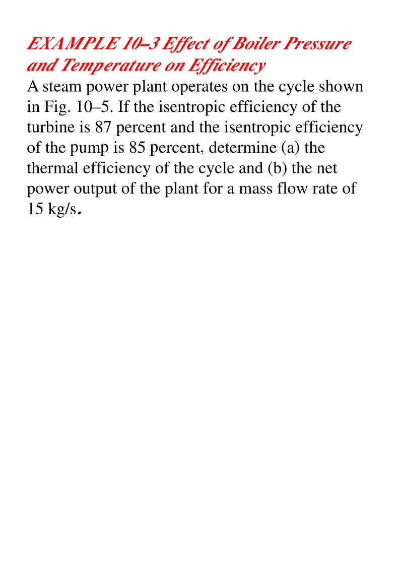
EXAMPLE 10–3 Effect of Boiler Pressure
and Temperature on Efficiency A steam power plant operates on the cycle shown
in Fig. 10–5. If the isentropic efficiency of theturbine is 87 percent and the isentropic efficiency
of the um is 85 ercent determine a the
thermal efficiency of the cycle and (b) the netpower output of the plant for a mass flow rate of
15 kg/s.
8/11/2019 Rankine Cycle Sum
http://slidepdf.com/reader/full/rankine-cycle-sum 39/76
Solution: A steam power plant operating on
the ideal Rankine cycle is considered.
The effects of superheating the steam to a higher
temperature and raising the boiler pressure on
thermal efficiency are to be investigated.
nalysis: The T- diagrams of the cycle for allthree cases are given in Fig. 10–10.
8/11/2019 Rankine Cycle Sum
http://slidepdf.com/reader/full/rankine-cycle-sum 40/76
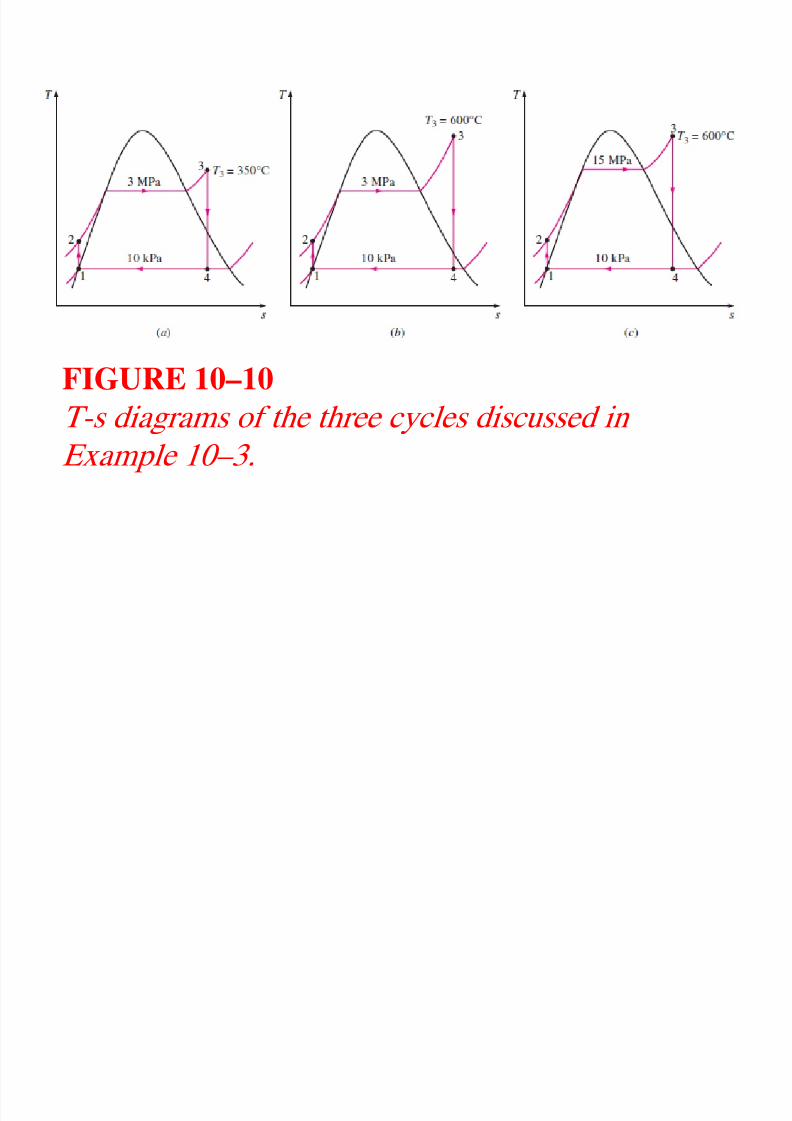
FIGURE 10–10
T-s diagrams of the three cycles discussed in
Example 10–3.
(a) This is the steam po er plant disc ssed in
8/11/2019 Rankine Cycle Sum
http://slidepdf.com/reader/full/rankine-cycle-sum 41/76
(a) This is the steam power plant discussed in
Example 10–1, except that the condenser pressureis lowered to 10 kPa. The thermal efficiency is
determined in a similar manner:
8/11/2019 Rankine Cycle Sum
http://slidepdf.com/reader/full/rankine-cycle-sum 42/76
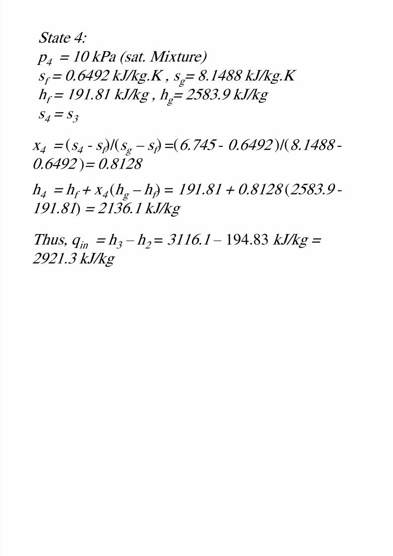
State 4:
p 4 = 10 kPa (sat. Mixture) s f = 0.6492 kJ/kg.K , s g = 8.1488 kJ/kg.K
h f = 191.81 kJ/kg , h g = 2583.9 kJ/kg
s 4 = s 3
x = s - s / s – s = 6.745 - 0.6492 / 8.1488 -
0.6492 )= 0.8128
h 4 = h f + x 4 (h g – h f ) = 191.81 + 0.8128 (2583.9 -
191.81 ) = 2136.1 kJ/kg
Thus, q in = h 3 – h 2 = 3116.1 – 194.83 kJ/kg =
2921.3 kJ/kg
8/11/2019 Rankine Cycle Sum
http://slidepdf.com/reader/full/rankine-cycle-sum 43/76
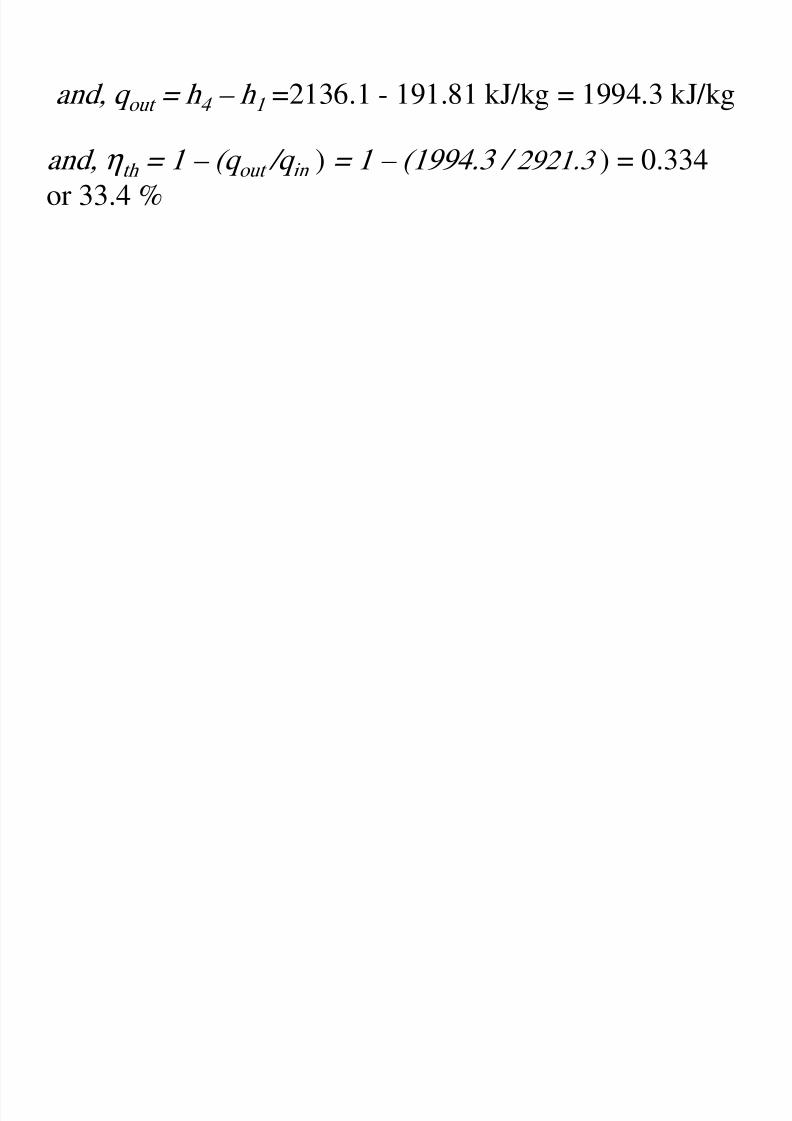
and, q out = h 4 – h 1 =2136.1 - 191.81 kJ/kg = 1994.3 kJ/kg
and, η th = 1 – (q out /q in ) = 1 – (1994.3 / 2921.3 ) = 0.334
or 33.4 %
8/11/2019 Rankine Cycle Sum
http://slidepdf.com/reader/full/rankine-cycle-sum 44/76
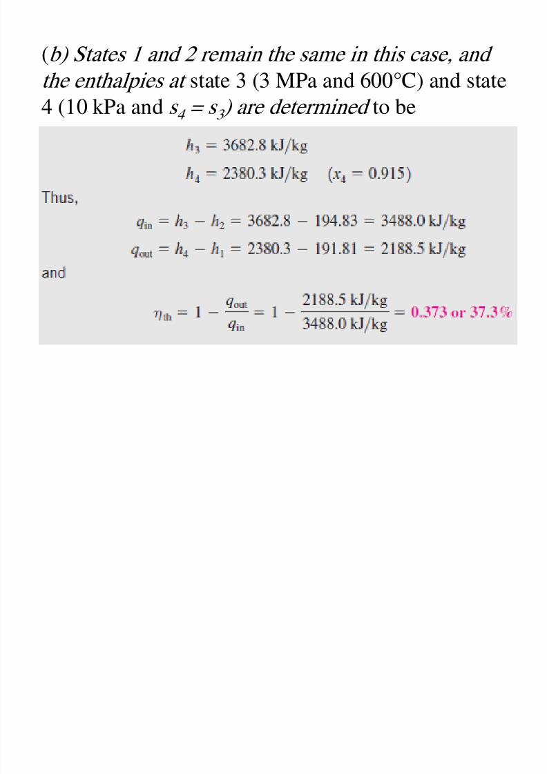
(b) States 1 and 2 remain the same in this case, and
the enthalpies at state 3 (3 MPa and 600°C) and state4 (10 kPa and s 4 = s 3 ) are determined to be
h f h h l ffi i i f
8/11/2019 Rankine Cycle Sum
http://slidepdf.com/reader/full/rankine-cycle-sum 45/76
Therefore, the thermal efficiency increases from 33.4
to 37.3 percent as a result of superheating the steamfrom 350 to 600°C. At the same time, the quality of
the steam increases from 81.3 to 91.5 percent (in
other words, the moisture content decreases from18.7 to 8.5 percent).
( ) St t 1 i th i thi b t th
8/11/2019 Rankine Cycle Sum
http://slidepdf.com/reader/full/rankine-cycle-sum 46/76
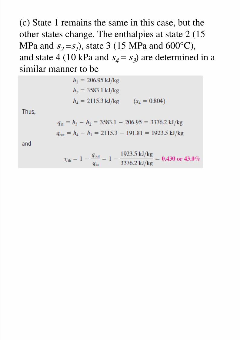
(c) State 1 remains the same in this case, but the
other states change. The enthalpies at state 2 (15MPa and s 2 =s 1 ), state 3 (15 MPa and 600°C),
and state 4 (10 kPa and s 4 = s 3 ) are determined in a
similar manner to be
Di i Th h l ffi i i f

8/11/2019 Rankine Cycle Sum
http://slidepdf.com/reader/full/rankine-cycle-sum 47/76
Discussion: The thermal efficiency increases from
37.3 to 43.0 percent as a result of raising the boilerpressure from 3 to 15 MPa while maintaining the
turbine inlet temperature at 600°C. At the same time,
however, the quality of the steam decreases from91.5 to 80.4 percent (in other words, the moisture
con en ncreases rom . o . percen .
10 5 ■ THE IDEAL REHEAT RANKINE
8/11/2019 Rankine Cycle Sum
http://slidepdf.com/reader/full/rankine-cycle-sum 48/76
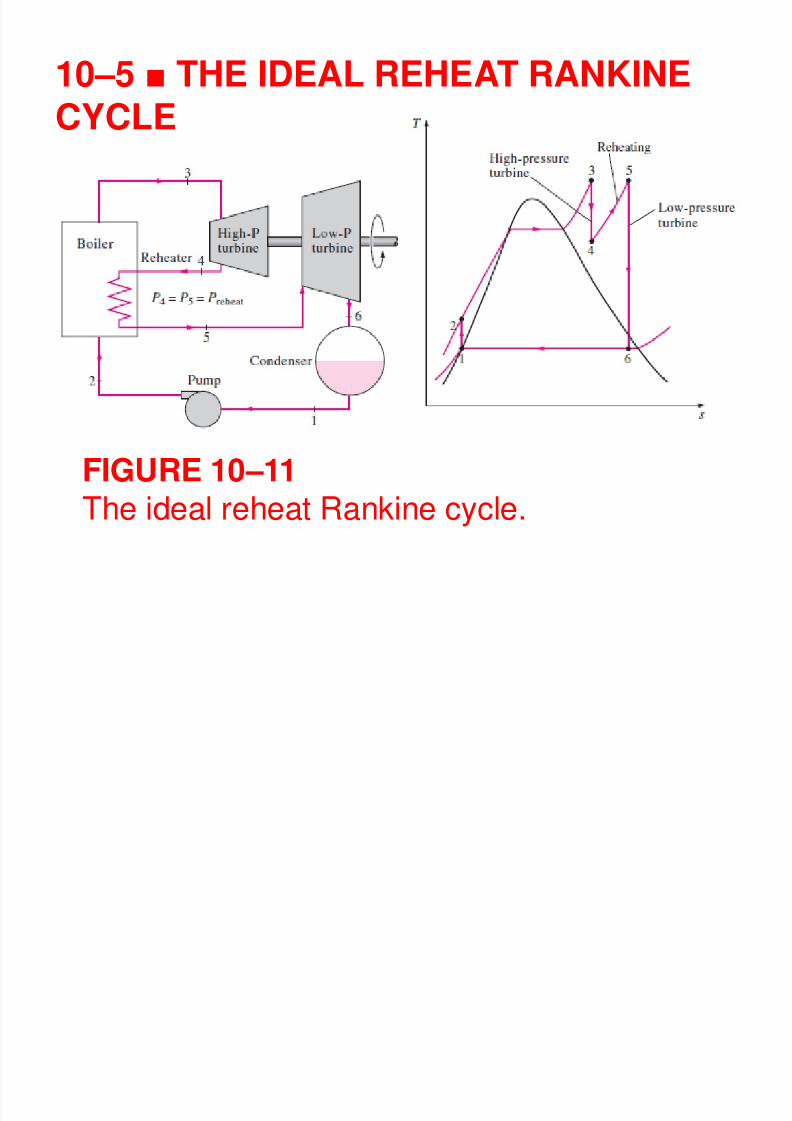
10–5 ■ THE IDEAL REHEAT RANKINE
CYCLE
FIGURE 10–11The ideal reheat Rankine cycle.
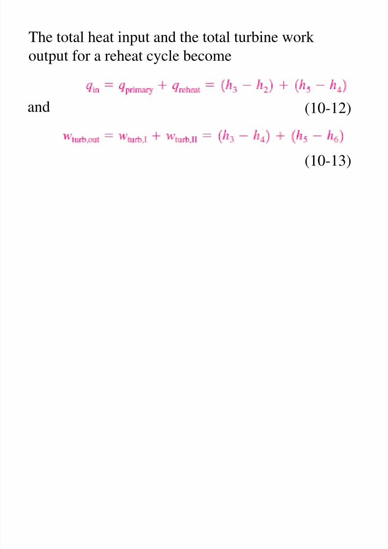
The total heat input and the total turbine work
8/11/2019 Rankine Cycle Sum
http://slidepdf.com/reader/full/rankine-cycle-sum 49/76
The total heat input and the total turbine work
output for a reheat cycle become
and (10-12)
(10-13)
EXAMPLE 10 4 Th Id l R h R ki C l
8/11/2019 Rankine Cycle Sum
http://slidepdf.com/reader/full/rankine-cycle-sum 50/76
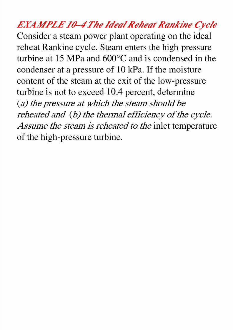
EXAMPLE 10–4 The Ideal Reheat Rankine Cycle
Consider a steam power plant operating on the idealreheat Rankine cycle. Steam enters the high-pressure
turbine at 15 MPa and 600°C and is condensed in the
condenser at a pressure of 10 kPa. If the moisture
content of the steam at the exit of the low-pressure
ur ne s no o excee . percen , e erm ne
(a) the pressure at which the steam should be
reheated and (b) the thermal efficiency of the cycle.
Assume the steam is reheated to the inlet temperatureof the high-pressure turbine.
Solution:
8/11/2019 Rankine Cycle Sum
http://slidepdf.com/reader/full/rankine-cycle-sum 51/76
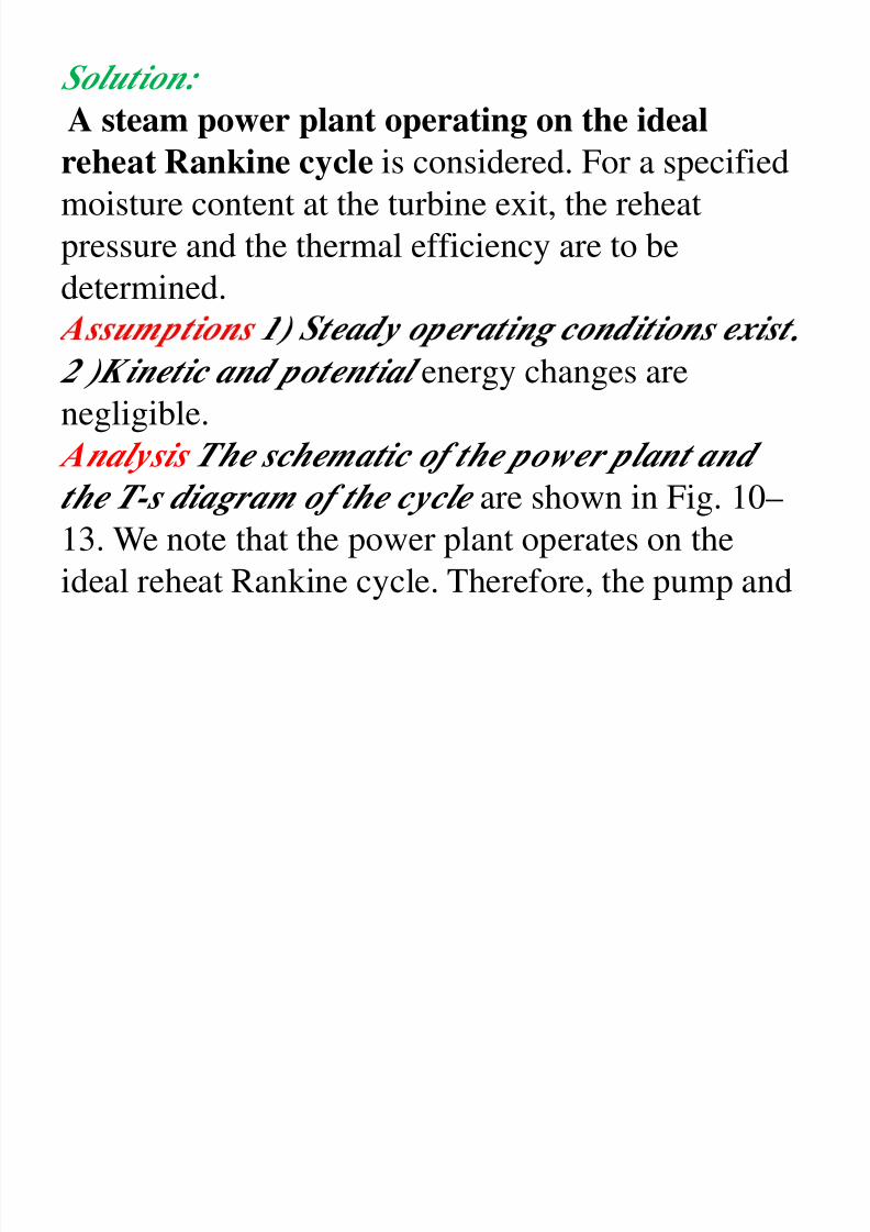
Solution:
A steam power plant operating on the idealreheat Rankine cycle is considered. For a specified
moisture content at the turbine exit, the reheat
pressure and the thermal efficiency are to bedetermined.
.
2 )Kinetic and potential energy changes arenegligible.
Analysis The schematic of the power plant and
the T-s diagram of the cycle are shown in Fig. 10–
13. We note that the power plant operates on the
ideal reheat Rankine cycle. Therefore, the pump and
the turbines are isentropic there are no pressure
8/11/2019 Rankine Cycle Sum
http://slidepdf.com/reader/full/rankine-cycle-sum 52/76
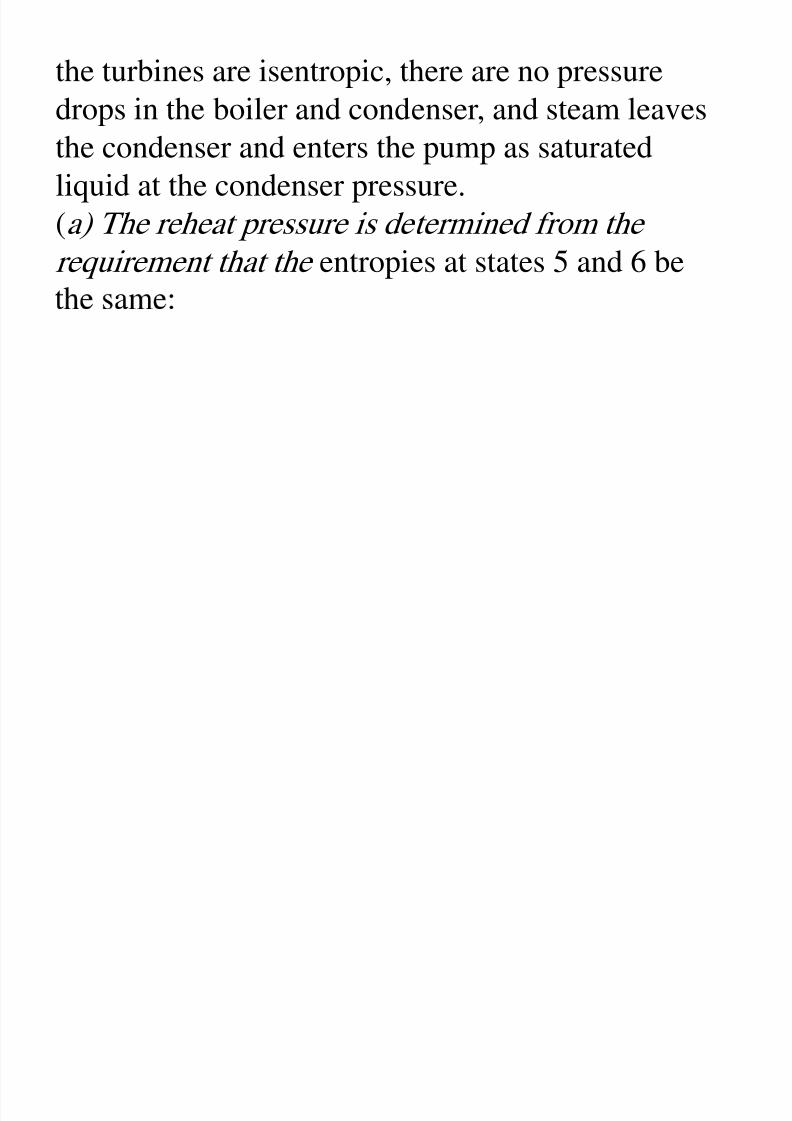
the turbines are isentropic, there are no pressure
drops in the boiler and condenser, and steam leavesthe condenser and enters the pump as saturated
liquid at the condenser pressure.
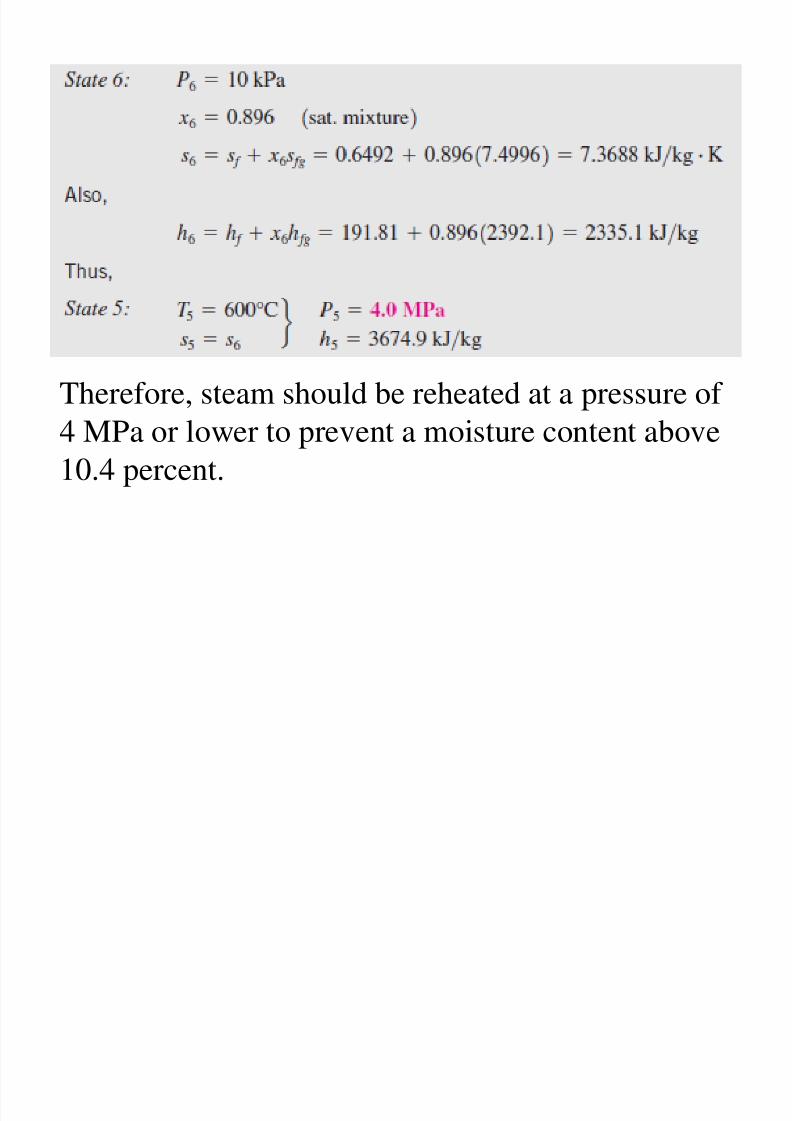
(a) The reheat pressure is determined from therequirement that the entropies at states 5 and 6 be
8/11/2019 Rankine Cycle Sum
http://slidepdf.com/reader/full/rankine-cycle-sum 53/76
Therefore, steam should be reheated at a pressure of
4 MPa or lower to prevent a moisture content above10.4 percent.
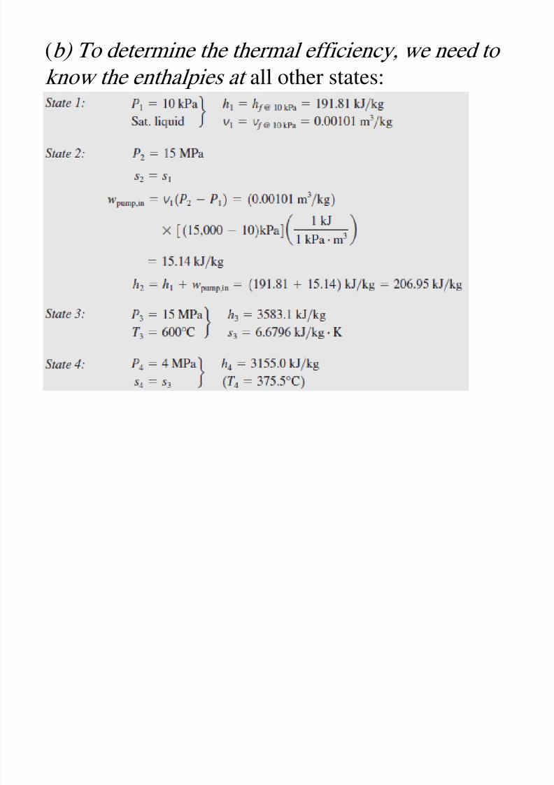
(b) To determine the thermal efficiency, we need to
8/11/2019 Rankine Cycle Sum
http://slidepdf.com/reader/full/rankine-cycle-sum 54/76
(b) To determine the thermal efficiency, we need to
know the enthalpies at all other states:
8/11/2019 Rankine Cycle Sum
http://slidepdf.com/reader/full/rankine-cycle-sum 55/76
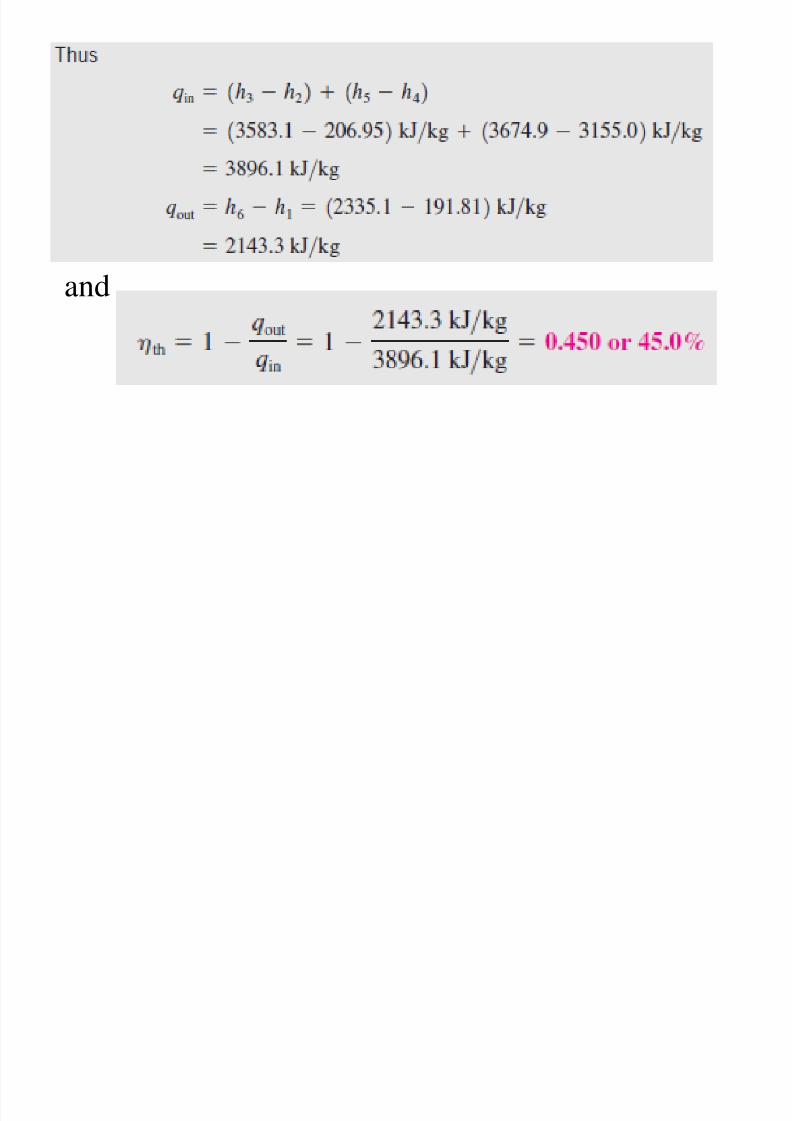
and
Discussion This problem was solved in Example
8/11/2019 Rankine Cycle Sum
http://slidepdf.com/reader/full/rankine-cycle-sum 56/76
Discussion This problem was solved in Example
10–3c for the same pressure and temperaturelimits but without the reheat process. A comparison
of the two results reveals that reheating reduces the
moisture content from 19.6 to 10.4 percent whileincreasing the thermal efficiency from 43.0 to 45.0
percen .
8/11/2019 Rankine Cycle Sum
http://slidepdf.com/reader/full/rankine-cycle-sum 57/76
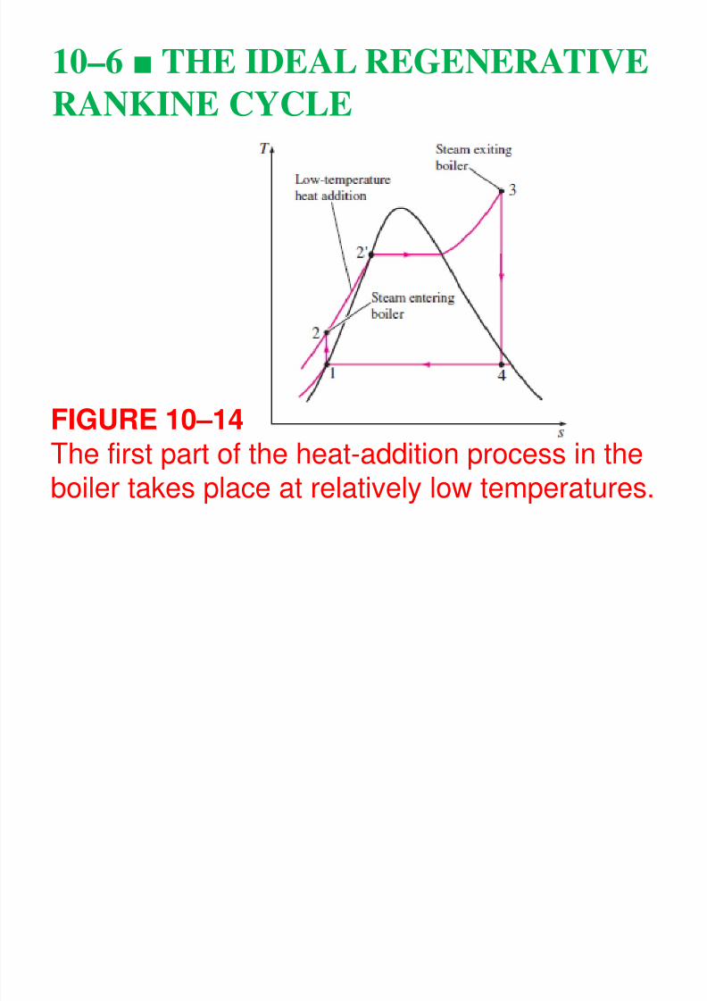
To remedy this shortcoming, we look for ways to
8/11/2019 Rankine Cycle Sum
http://slidepdf.com/reader/full/rankine-cycle-sum 58/76
y g y
raise the temperature of the liquid leaving the pump(called the feedwater) before it enters the boiler.
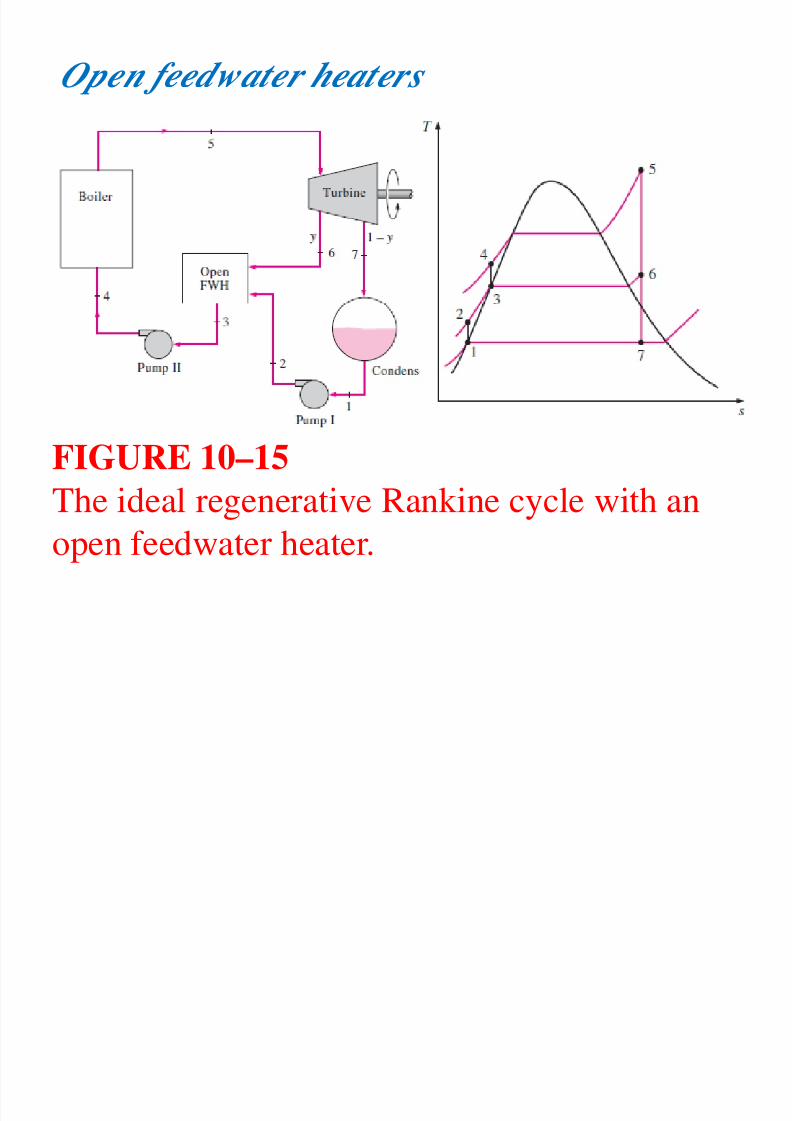
A feedwater heater is basically a heat exchangerwhere heat is transferred from the steam to the
(open feedwater heaters ) or without mixing them(closed feedwater heaters ).
Regeneration with both types of feedwater heaters
is discussed below.
Open feedwater heaters
8/11/2019 Rankine Cycle Sum
http://slidepdf.com/reader/full/rankine-cycle-sum 59/76
Op f
FIGURE 10–15
The ideal regenerative Rankine cycle with an
open feedwater heater.
In the analysis of steam power plants, it is
8/11/2019 Rankine Cycle Sum
http://slidepdf.com/reader/full/rankine-cycle-sum 60/76
y p p ,
more convenient to work with quantitiesexpressed per unit mass of the steam flowing
through the boiler.
For each 1 kg of steam leaving the boiler, y kg
ex ands artiall in the turbine and is extracted
at state 6. The remaining (1- y) kg expandscompletely to the condenser pressure.
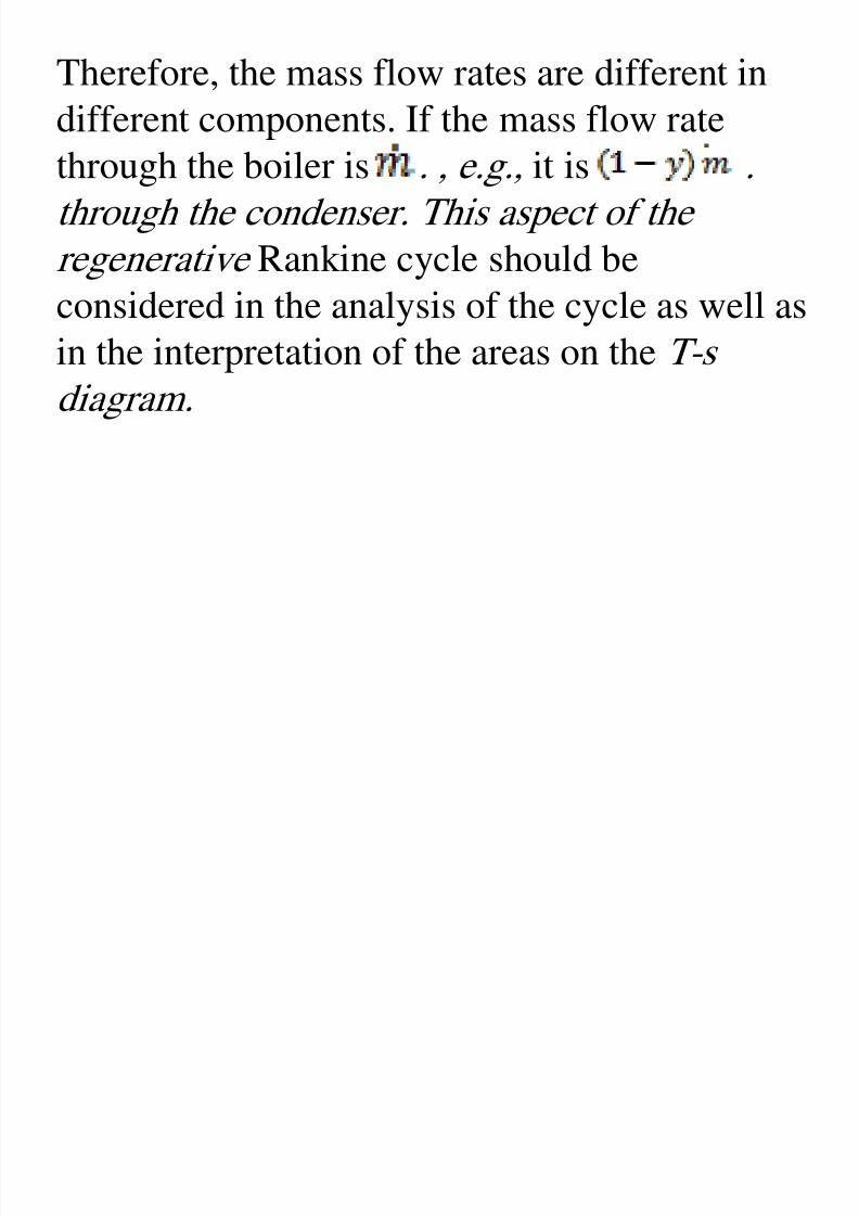
Therefore, the mass flow rates are different in
8/11/2019 Rankine Cycle Sum
http://slidepdf.com/reader/full/rankine-cycle-sum 61/76
different components. If the mass flow ratethrough the boiler is . , e.g., it is .
through the condenser. This aspect of the
regenerative Rankine cycle should beconsidered in the analysis of the cycle as well as
in the interpretation of the areas on the T-sdiagram.
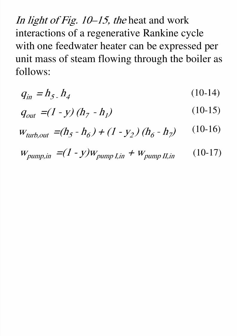
In light of Fig. 10–15, the heat and work
8/11/2019 Rankine Cycle Sum
http://slidepdf.com/reader/full/rankine-cycle-sum 62/76
interactions of a regenerative Rankine cyclewith one feedwater heater can be expressed per
unit mass of steam flowing through the boiler as
follows:
q in = 5 - 4 -
q out =(1 - y) (h 7 - h 1 ) (10-15)
w turb,out =(h 5 - h 6 ) + (1 - y 2 ) (h 6 - h 7 ) (10-16)
w pump,in =(1 - y)w pump I,in + w pump II,in (10-17)
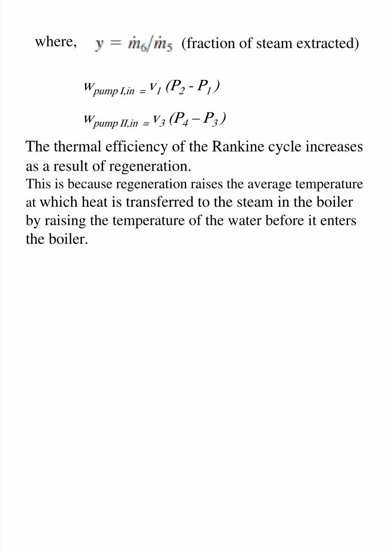
where, (fraction of steam extracted)
8/11/2019 Rankine Cycle Sum
http://slidepdf.com/reader/full/rankine-cycle-sum 63/76
w e e,
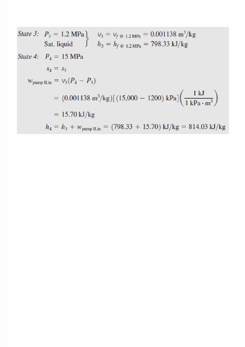
w pump I,in = v 1 (P 2 - P 1 )
(fraction of steam extracted)
w pump II,in = v 3 (P 4 – P 3 )
as a result of regeneration.This is because regeneration raises the average temperature
at which heat is transferred to the steam in the boiler
by raising the temperature of the water before it entersthe boiler.
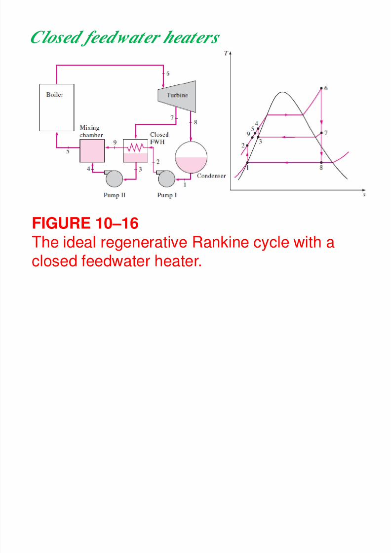
Closed feedwater heaters
8/11/2019 Rankine Cycle Sum
http://slidepdf.com/reader/full/rankine-cycle-sum 64/76
FIGURE 10–16The ideal regenerative Rankine cycle with aclosed feedwater heater.
Another type of feedwater heater frequently
8/11/2019 Rankine Cycle Sum
http://slidepdf.com/reader/full/rankine-cycle-sum 65/76
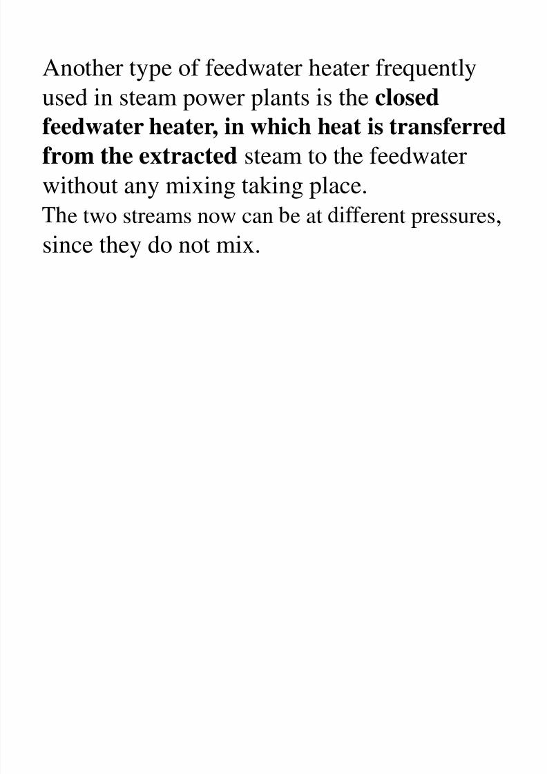
Another type of feedwater heater frequently
used in steam power plants is the closed
feedwater heater, in which heat is transferred
from the extracted steam to the feedwaterwithout any mixing taking place.
e two streams now can e at erent pressures,
since they do not mix.
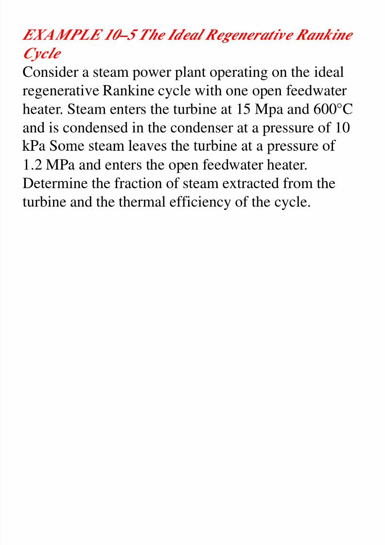
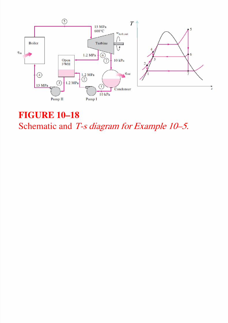
EXAMPLE 10–5 The Ideal Regenerative Rankine
8/11/2019 Rankine Cycle Sum
http://slidepdf.com/reader/full/rankine-cycle-sum 66/76
Cycle Consider a steam power plant operating on the ideal
regenerative Rankine cycle with one open feedwater
heater. Steam enters the turbine at 15 Mpa and 600°Cand is condensed in the condenser at a pressure of 10
1.2 MPa and enters the open feedwater heater.Determine the fraction of steam extracted from the
turbine and the thermal efficiency of the cycle.
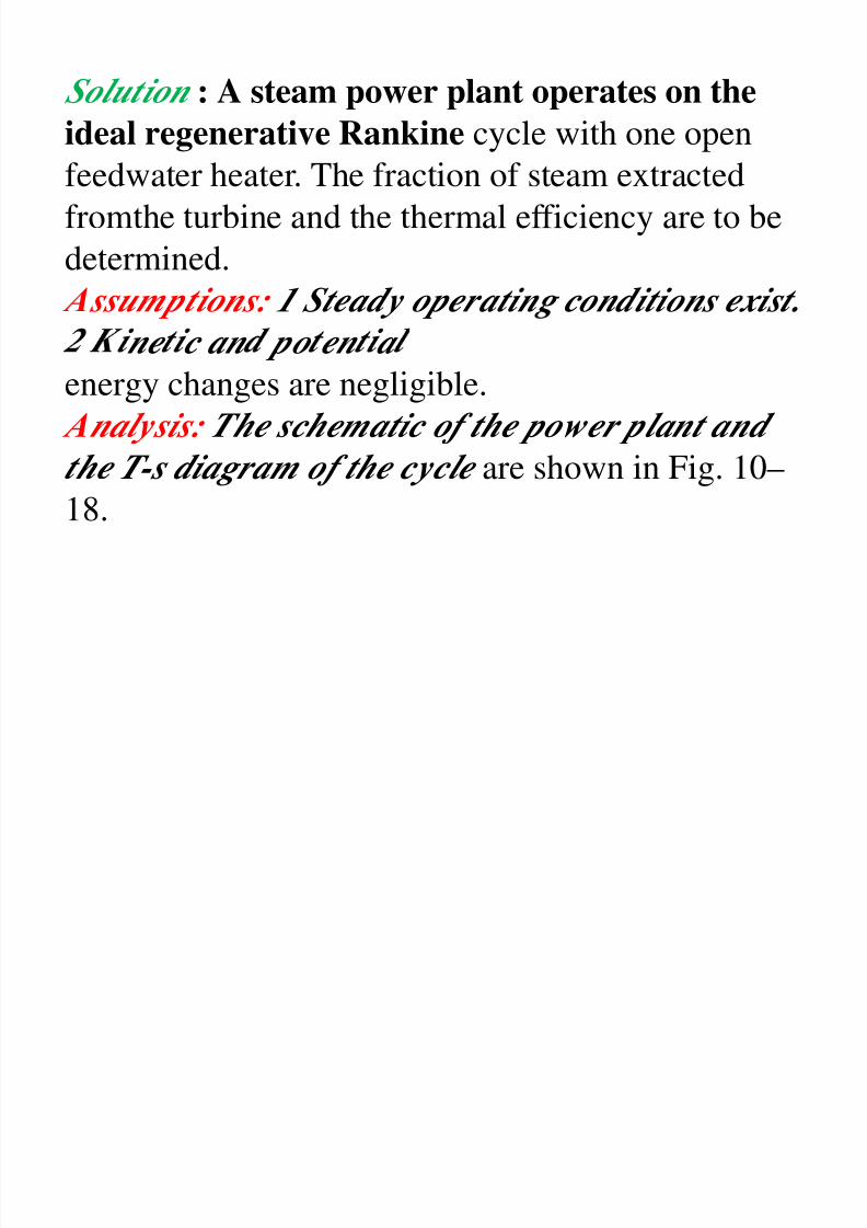
Solution : A steam power plant operates on the
8/11/2019 Rankine Cycle Sum
http://slidepdf.com/reader/full/rankine-cycle-sum 67/76
p p p
ideal regenerative Rankine cycle with one openfeedwater heater. The fraction of steam extracted
fromthe turbine and the thermal efficiency are to be
determined. Assumptions: 1 Steady operating conditions exist.
ne c an po en a
energy changes are negligible.
Analysis: The schematic of the power plant and
the T-s diagram of the cycle are shown in Fig. 10–
18.
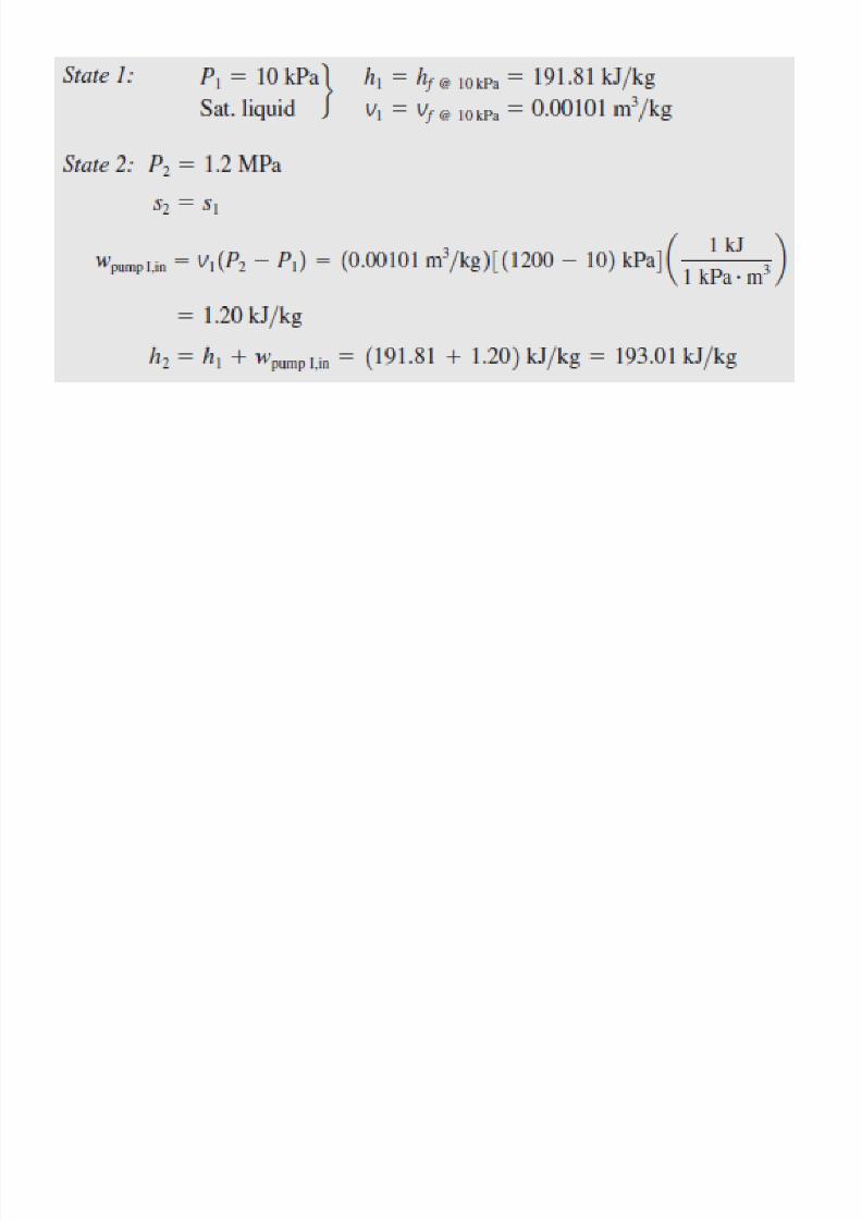
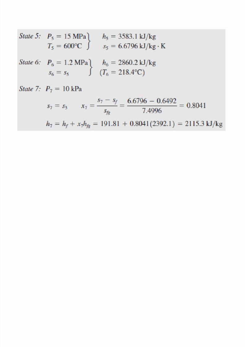
We note that the power plant operates on the ideal

8/11/2019 Rankine Cycle Sum
http://slidepdf.com/reader/full/rankine-cycle-sum 68/76
regenerative Rankine cycle. Therefore, the pumpsand the turbines are isentropic; there are no pressure
drops in the boiler, condenser, and feedwater heater;
and steam leaves the condenser and the feedwaterheater as saturated liquid. First, we determine the
en a p es a var ous s a es:
8/11/2019 Rankine Cycle Sum
http://slidepdf.com/reader/full/rankine-cycle-sum 69/76
T
8/11/2019 Rankine Cycle Sum
http://slidepdf.com/reader/full/rankine-cycle-sum 70/76
FIGURE 10–18
Schematic and T-s diagram for Example 10–5.
8/11/2019 Rankine Cycle Sum
http://slidepdf.com/reader/full/rankine-cycle-sum 71/76
8/11/2019 Rankine Cycle Sum
http://slidepdf.com/reader/full/rankine-cycle-sum 72/76
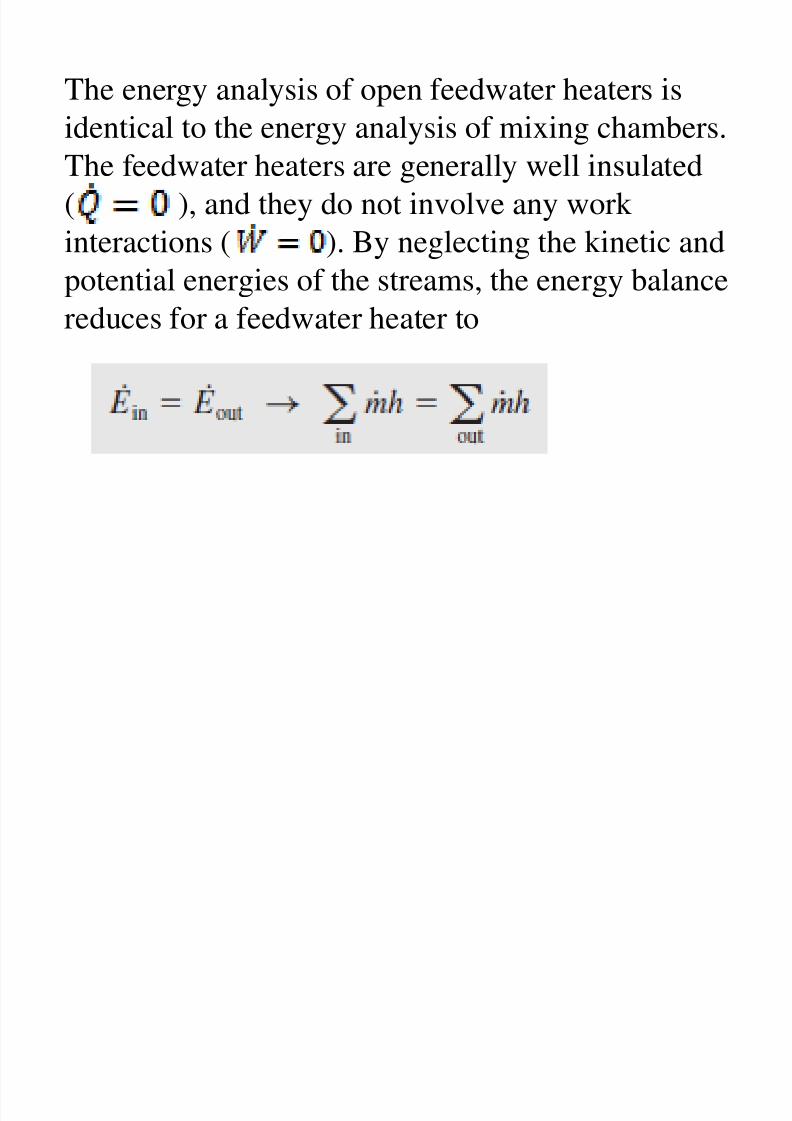
The energy analysis of open feedwater heaters is
8/11/2019 Rankine Cycle Sum
http://slidepdf.com/reader/full/rankine-cycle-sum 73/76
identical to the energy analysis of mixing chambers.The feedwater heaters are generally well insulated
( ), and they do not involve any work
interactions ( ). By neglecting the kinetic andpotential energies of the streams, the energy balance
reduces for a feedwater heater to
or
8/11/2019 Rankine Cycle Sum
http://slidepdf.com/reader/full/rankine-cycle-sum 74/76
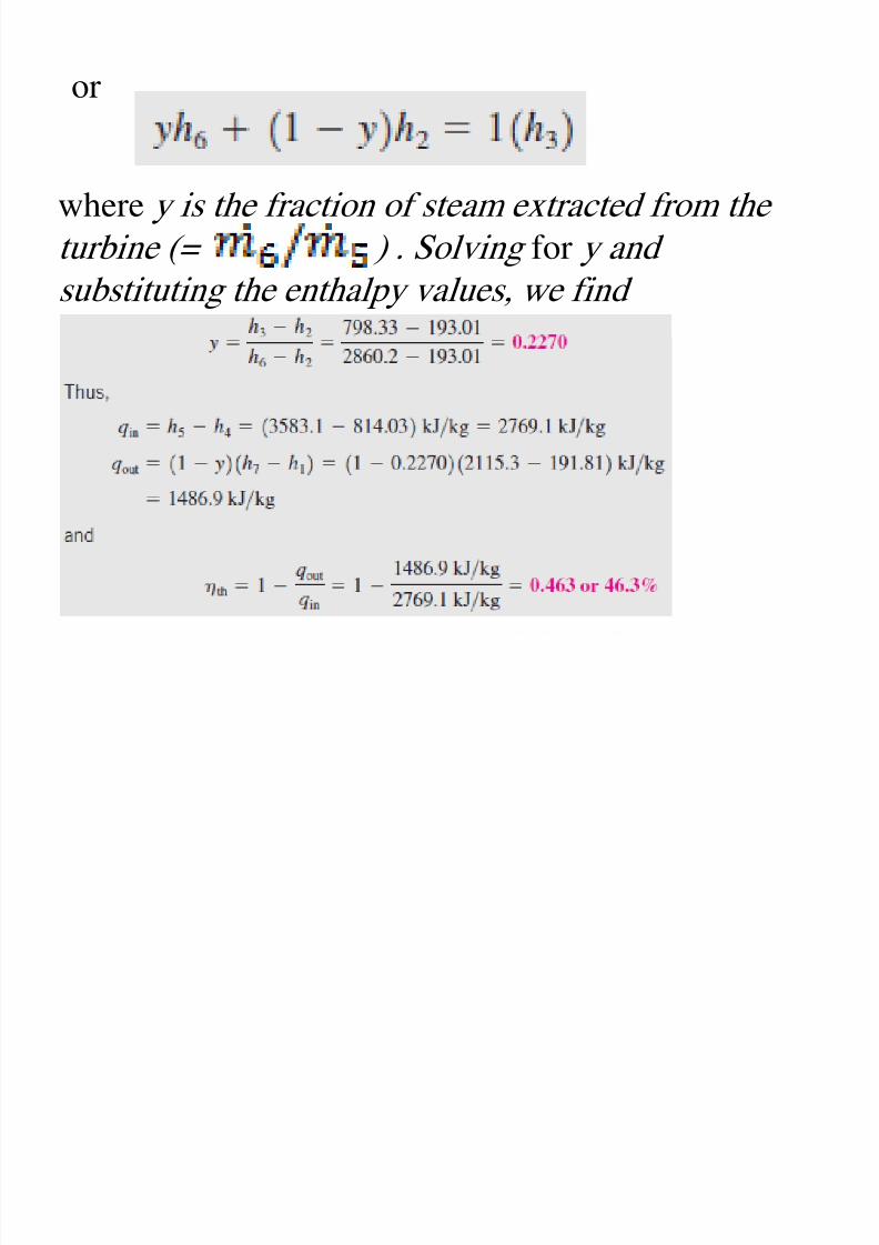
where y is the fraction of steam extracted from the
turbine (= ) . Solving for y andsubstituting the enthalpy values, we find
Discussion This problem was worked out in
8/11/2019 Rankine Cycle Sum
http://slidepdf.com/reader/full/rankine-cycle-sum 75/76
Example 10–3c for the same pressure andtemperature limits but without the regeneration
process. A comparison of the two results reveals
that the thermal efficiency of the cycle hasincreased from 43.0 to 46.3 percent as a result of
.
kJ/kg, but the heat input decreased by 607 kJ/kg,which results in a net increase in the thermal
efficiency.
Homework

8/11/2019 Rankine Cycle Sum
http://slidepdf.com/reader/full/rankine-cycle-sum 76/76
10–2C , 10–3C , 10–4C , 10–5C , 10–6C , 10–7C , 10–8C , 10–9C , 10–12C ,
10–13C , 10–14 , 10-16, 10-20, 10-21 ,
, , , , , –
, 10-34, , 10-36, 10–37, 10–38 , 10–42C , 10–43C , 10–47 , 10–48 , 10–51
, 10–52 , 10–56 , 10–58.