ranger compass model: 515 - college of … compass model: 515 2 your silva ranger compass is a...
TRANSCRIPT
A PRECISION INSTRUMENT DESIGNED FOR PROFESSIONAL USE.INSTRUCTION MANUAL
RANGER COMPASSmodel: 515
2
Your Silva Ranger Compass is a precision instrument made by experi-enced specialists in this field; it is the finest hand compass available for professional use. Your Silva Ranger is finely crafted to withstand rigors associated with the out-door professions. It is a rugged, durable piece of equipment that, with proper care, will remain dependable and accurate.
We recommend that you read this manual to understand the basic functions of the compass. When you read, keep in mind that no two compass applications are identical. The instructions given here are intended to provide you with a working knowledge that you will be able to apply in almost any situation.
The illustrated 360 Degree Graduations are based on standard dial graduations of 360 degrees, in 2º increments. With this graduation North is 0º and increases clockwise so East is 90º, South is 180º, West is 270º and 360º is again North. 0º and 360º are the same direction.
The Silva Ranger Model 515CLQ has Quadrant Graduations. With this graduation North is 0º and increases clockwise so East is 90º then it decreases so South is 0º then increases so West is 90º and then decreases so North is 0º. Instructions in this manual will apply to this graduation except when it is necessary to refer to the proper “quadrant,” such as North 20º East, or North 15º West, or South 40º East or South l0º West.

3
compass cover
luminous points
base plate
black clinometer pointer
magnetic needle with red north
2X magnifier
scale in mm
sight
mirror
sighting line
index pointer
orienting arrow with red north endmeridian lines
liquid filled capsule
bezel with 2º graduations
scale in inches
4
GENERAL SUGGESTIONSYour Silva Ranger compass may be used for finding directions with or without the
aid of the sighting mirror. LEARN BOTH WAYS.1. When extreme accuracy required: With the sighting mirror, hold compass at eye
level with cover opened to an acute angle.2. When quick accuracy required: With the sighting line as a direction pointer, hold
the compass at waist level with cover wide open. In either instance, the compass must be held level enough to permit the needle to swing freely.
Always check compass function prior to using it in the field. Be aware that expos-ing your compass to articles with iron content (a magnetic field) can cause the red end of the needle to align with South, a condition called reverse polarity. Something as simple as being placed next to a pair of scissors or knife for a length of time, microwaves, high tension wires, stereo speakers, magnets, etc. can cause this problem.
A small bubble may form in the liquid compass, but it has no influence on accuracy. The appearance and disappearance of this bubble is due to changes in temperature and atmospheric pressure. Bubbles larger than 1/4" diameter, however, should be viewed with suspicion and probably are caused by a leaking capsule.
To increase their brilliance, expose the luminous points to bright light before use.
Protect your compass from high temperatures extremes. The heat expanded liquid could damage the capsule.
5
THE CLINOMETERThe SILVA Ranger compasses are practical instruments for measuring angles of
inclination. The long side of the compass coincides with the slope of the terrain. Measure an angle of inclination in the following way:1. Open the lid completely.2. Turn the dial so that the cardinal point “W” on the dial is set at the index pointer.3. Hold he compass at eye level with arms out-stretched so that the clinometer
needle is hanging vertically and follows the scale in the bottom of the compass housing. “S” on the compass should point down.
4. Let one long side of the compass coincide with the slope of the terrain— the inclination you wish to measure.
5. Read the angle of inclination at the point of the clinometer needle.
RULES OF USETwo separate sets of rules apply to the use of a magnetic compass. One set applies
if you work “from map to terrain.” In this case you take “map bearings.” In the fol-lowing, Sections A, B, C, D and E deal with “from map to terrain.”
Exactly opposite rules apply if you work “from terrain to map.” In this case you use “field bearings,” also called “magnetic bearings” and “compass bearings,” Sections F, G and H deal with “from terrain to map.”
The word “map” is broadly interpreted to also include charts, descriptions and even a mental picture of the terrain.
6
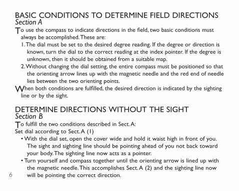
BASIC CONDITIONS TO DETERMINE FIELD DIRECTIONSSection ATo use the compass to indicate directions in the field, two basic conditions must
always be accomplished. These are:1. The dial must be set to the desired degree reading. If the degree or direction is
known, turn the dial to the correct reading at the index pointer. If the degree is unknown, then it should be obtained from a suitable map.
2. Without changing the dial setting, the entire compass must be positioned so that the orienting arrow lines up with the magnetic needle and the red end of needle lies between the two orienting points.
When both conditions are fulfilled, the desired direction is indicated by the sighting line or by the sight.
DETERMINE DIRECTIONS WITHOUT THE SIGHTSection BTo fulfill the two conditions described in Sect. A:Set dial according to Sect. A (1)
• With the dial set, open the cover wide and hold it waist high in front of you. The sight and sighting line should be pointing ahead of you not back toward your body. The sighting line now acts as a pointer.
• Turn yourself and compass together until the orienting arrow is lined up with the magnetic needle. This accomplishes Sect. A (2) and the sighting line now will be pointing the correct direction.
7
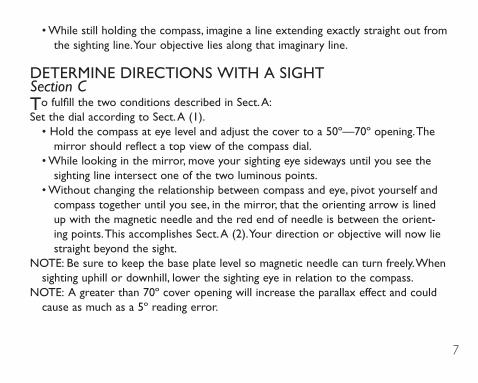
• While still holding the compass, imagine a line extending exactly straight out from the sighting line. Your objective lies along that imaginary line.
DETERMINE DIRECTIONS WITH A SIGHTSection CTo fulfill the two conditions described in Sect. A:Set the dial according to Sect. A (1).
• Hold the compass at eye level and adjust the cover to a 50º—70º opening. The mirror should reflect a top view of the compass dial.
• While looking in the mirror, move your sighting eye sideways until you see the sighting line intersect one of the two luminous points.
• Without changing the relationship between compass and eye, pivot yourself and compass together until you see, in the mirror, that the orienting arrow is lined up with the magnetic needle and the red end of needle is between the orient-ing points. This accomplishes Sect. A (2). Your direction or objective will now lie straight beyond the sight.
NOTE: Be sure to keep the base plate level so magnetic needle can turn freely. When sighting uphill or downhill, lower the sighting eye in relation to the compass.
NOTE: A greater than 70º cover opening will increase the parallax effect and could cause as much as a 5º reading error.
8
OBTAIN A BEARING FROM A MAPSection DWe state in Sect. A, that one of the two conditions for using the Silva Ranger is to
set the dial at the desired degree reading. If this degree or bearing is not known, it can be determined from a map. Your compass is also a protractor with a transpar-ent bottom in the dial housing. Two steps are required:1. Lay the compass on the map so either the inch scale or the millimeter scale
is exactly on (or parallel with) the line on the map you wish to travel, and the hinged cover points in the direction of travel.
2. Hold the compass in position on the map, turn the dial so the meridian lines of the compass are exactly parallel with any meridian (North-South) line on the map, and the letter “N” on top of the dial is toward North on the map.
Remove the compass from the map. These two steps set your compass for the degree reading to your destination. This reading may be read at the index pointer. You fulfilled the first basic condition in Sect. A. Proceed to Sect. B or C.
ABOUT DECLINATIONSection EThe magnetic needle in a compass is attracted by the magnetism of the Earth. This is
why it always points to the constantly shifting Magnetic North where the magnetic lines of force come together. There is another “North Pole.” True North is static and located geographically, maps and directions usually are based on True North.
9
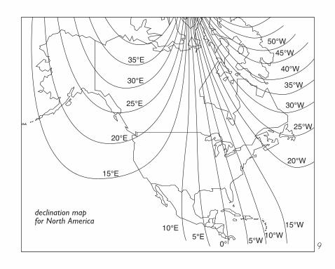
declination map for North America
10
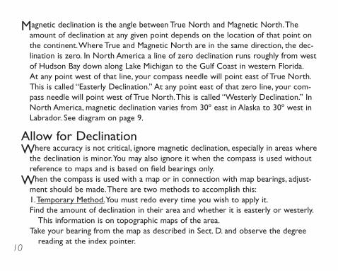
Magnetic declination is the angle between True North and Magnetic North. The amount of declination at any given point depends on the location of that point on the continent. Where True and Magnetic North are in the same direction, the dec-lination is zero. In North America a line of zero declination runs roughly from west of Hudson Bay down along Lake Michigan to the Gulf Coast in western Florida. At any point west of that line, your compass needle will point east of True North. This is called “Easterly Declination.” At any point east of that zero line, your com-pass needle will point west of True North. This is called “Westerly Declination.” In North America, magnetic declination varies from 30º east in Alaska to 30º west in Labrador. See diagram on page 9.
Allow for DeclinationWhere accuracy is not critical, ignore magnetic declination, especially in areas where
the declination is minor. You may also ignore it when the compass is used without reference to maps and is based on field bearings only.
When the compass is used with a map or in connection with map bearings, adjust-ment should be made. There are two methods to accomplish this:1. Temporary Method. You must redo every time you wish to apply it. Find the amount of declination in their area and whether it is easterly or westerly.
This information is on topographic maps of the area. Take your bearing from the map as described in Sect. D. and observe the degree
reading at the index pointer.
11
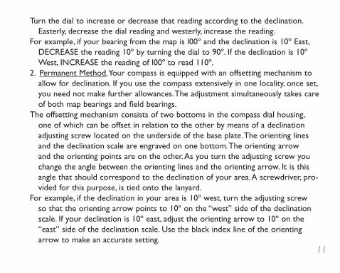
Turn the dial to increase or decrease that reading according to the declination. Easterly, decrease the dial reading and westerly, increase the reading.
For example, if your bearing from the map is l00º and the declination is 10º East, DECREASE the reading 10º by turning the dial to 90º. If the declination is 10º West, INCREASE the reading of l00º to read 110º.
2. Permanent Method. Your compass is equipped with an offsetting mechanism to allow for declination. If you use the compass extensively in one locality, once set, you need not make further allowances. The adjustment simultaneously takes care of both map bearings and field bearings.
The offsetting mechanism consists of two bottoms in the compass dial housing, one of which can be offset in relation to the other by means of a declination adjusting screw located on the underside of the base plate. The orienting lines and the declination scale are engraved on one bottom. The orienting arrow and the orienting points are on the other. As you turn the adjusting screw you change the angle between the orienting lines and the orienting arrow. It is this angle that should correspond to the declination of your area. A screwdriver, pro-vided for this purpose, is tied onto the lanyard.
For example, if the declination in your area is 10º west, turn the adjusting screw so that the orienting arrow points to 10º on the “west” side of the declination scale. If your declination is 10º east, adjust the orienting arrow to 10º on the “east” side of the declination scale. Use the black index line of the orienting arrow to make an accurate setting.
12
NOTE: The declination offsetting mechanism is set at zero at the factory. Use the zero setting for all compass operations which involve no allowance for declination or in which the temporary allowance is being used. If the declination scale does not read zero, set it to zero with the adjusting screw.
NOTE: When the orienting arrow is not set at zero, it becomes obvious that the orienting lines and the orienting arrow serve different purposes. The orienting lines are used to line up with orienting lines on the map. The orienting arrow is used to line up with the magnetic needle when using compass in the field.
TAkE A BEARINGSection FA“bearing” is the direction or the degree reading from one object to another. One
of those objects is usually YOU. To “take” a bearing means to DETERMINE the direction from one object to another.1. Bearings are taken from a map as in Sect. D. The “bearing” is the degree reading
indicated at the index pointer.2. Bearings can be taken on the terrain, by reversing the steps in Sect. B and C.
When using the compass without the sight, open the cover wide and hold it level, at waist high, in front of you. The sight and sighting line should be pointing straight ahead of you. The sighting line acts as a pointer. Pivot yourself and com-pass together until the sighting line points straight to the object on which you are taking the bearing. Without changing position of the compass, carefully turn the dial until the orienting arrow and the magnetic needle are lined up and with

13
the red end of needle lying between the two orienting points. The “bearing” to your object is now the degree reading indicated at the index pointer.
3. Bearings can be taken by using the sight. Hold the compass at eye level and adjust cover so top of the dial is seen in mirror. Face toward your object and sight object across compass sight. Look in the mirror and adjust position of compass so that the sighting line intersects one of the luminous points. While you simultaneously see your object across the sight, and the sighting line across one of the luminous points, turn the dial so that the orienting arrow is lined up with the needle, red end between the orienting points. The “bearing” to your object is now the degree reading indicated at the index pointer.
ADjUST FIELD BEARINGS FOR DECLINATIONSection G
1. The permanent adjustment for declination eliminates need for further adjust-ment.
2. To accomplish the temporary adjustment for field bearing declination: Take a bearing as described in Sect. F and observe the degree reading at the index pointer. Turn the dial to increase or decrease that reading according to the dec-lination. If declination of your area is easterly, increase your dial reading by the amount of declination. If westerly, decrease the reading.
For example, assume your field bearing is 100º. If the declination is 10º east, INCREASE the reading 10º by turning the dial to read 110º. If the declination is 10º west, DECREASE the reading of 100º to read 90º.
14
NOTE: The instructions for a “temporary” adjustment for declination of a field bear-ing are exactly opposite from the temporary adjustment of a map bearing.
NOTE: The declination scale should be set at zero for all compass operations which involve no allowance for declination; or when the temporary method is used.
A “Short-Cut” Method to Deal with Declination:
When the compass is used with a map, no adjustment is necessary if the orienting lines on the map are drawn according to Magnetic North instead of True North. Most topographic maps are drawn according to True North and the orienting lines are also according to True North.
Draw your own orienting line according to Magnetic North:On all topographic maps, there is a declination diagram near the bottom. The star line
designates True North and is parallel with the orienting lines. However, the single barb arrow designates Magnetic North. Draw your own Magnetic North orient-ing lines by drawing 1" or 2" lines across the map that are parallel to the Magnetic North arrow. Use these lines instead of the True North lines when setting your compass and you will not need to adjust for declination.
PLOT LOCATIONS ON A MAPSection ITriangulation method:Find two specific sites (a) and (b) on the map which you recognize, by sight, on the
terrain. These are the chosen points from which to take cross bearings.
15
Adjust your compass for the declination of your area by the permanent method.Take a bearing to the first site (a)— without disturbing the dial setting.Place the compass on the map so that either side of the base plate intersects the
symbol for the chosen site (a). keep the edge of compass base plate on the symbol and turn entire compass on the map until the compass orienting lines in the bot-tom of the dial are parallel with the orienting lines on the map, and so that the orienting arrow points upward on the map (North).
NOTE: Orienting arrow may be slightly off of North because of declination adjust-ment.
Draw a line on the map along the edge of the compass, intersecting the symbol. You are somewhere along this line. To establish your position along this line, you need another bearing.
Take a bearing to the second site (b) and mark a line as you did with site (a). This line will intersect the first line. Where the lines cross is your exact position.
BE EXPERT WITH MAP AND COMPASS, Second EditionBjörn kjellström
This new and enlarged edition includes everything you need to know about the skill of Orienteering; how to use a map and compass, alone or together. The text includes a series of games and exercises which encourage self-training. Each copy of the book also contains a sample training map to help you put newfound knowl-edge into practice. Required reading for the beginner in map and compass work.

16Johnson Outdoors Gear LLC. © 2009 p/n 5793150C 2-09
Johnson Outdoors Gear LLC625 Conklin Road
Binghamton, NY 13903www.silvausa.com
Johnson Outdoors Inc. Canada4180 Harvester Road
Burlington, Ontario Canada L7L 6B6 1.905.634.0023 Fax 1.800.661.1170