range q - tekon.com.ua€¦ · emergency shut down (esd) facility. q-pak - optional extras with the...
TRANSCRIPT
Redefining Flow Control
A4/US
US
A4
A4/US
US
A4
A4 US
US
A4
US
A4
A4 US
PUB007-001-00Issue 01/12
Formerly E610E. As part of a process of on-going product development, Rotork reserves the right to amend and change specifications without prior notice. Published data may be subject to change. For the very latest version release, visit our website at www.rotork.com
The name Rotork is a registered trademark. Rotork recognises all registered trademarks. Published and produced in the UK by Rotork Controls Limited. POWSH0112
www.rotork.com
A full listing of our worldwide sales and service network is available on our website.
UKRotork plctel +44 (0)1225 733200fax +44 (0)1225 333467email [email protected]
Electric Actuators and Control Systems
Fluid Power Actuators and Control Systems
Gearboxes and Gear Operators
Projects, Services and Retrofit
USARotork Controls Inc.tel +1 (585) 247 2304fax +1 (585) 247 2308email [email protected]
Watertight Single-Phase Electric Quarter-turn Actuators for
part-turn valves and dampers
Q Range
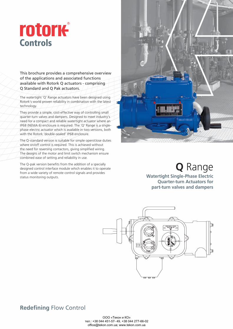
This brochure provides a comprehensive overview of the applications and associated functions available with Rotork Q actuators - comprising Q Standard and Q Pak actuators.
The watertight ‘Q’ Range actuators have been designed using Rotork’s world proven reliability in combination with the latest technology.
They provide a simple, cost-effective way of controlling small quarter-turn valves and dampers. Designed to meet industry’s need for a compact and reliable watertight actuator where an IP68 (NEMA 6) enclosure is required. The ‘Q’ Range is a single-phase electric actuator which is available in two versions, both with the Rotork ‘double-sealed’ IP68 enclosure.
The Q-standard version is suitable for simple open/close duties where on/off control is required. This is achieved without the need for reversing contactors, giving simplified wiring. The designs of the motor and limit switch mechanism ensure combined ease of setting and reliability in use.
The Q-pak version benefits from the addition of a specially designed control interface module which enables it to operate from a wide variety of remote control signals and provides status monitoring outputs.
Watertight Single-Phase Electric Quarter-turn Actuators for part-turn valves and dampers
Q Range
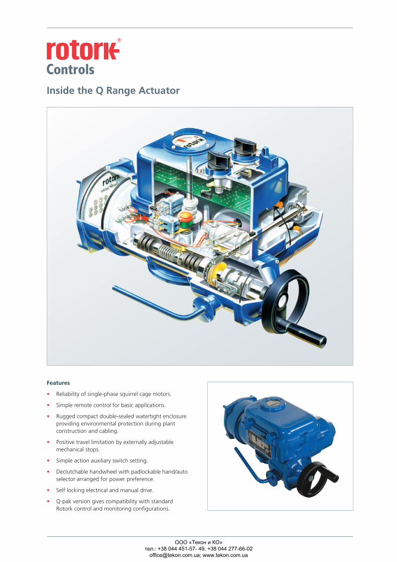
Features
• Reliability of single-phase squirrel cage motors.
• Simple remote control for basic applications.
• Rugged compact double-sealed watertight enclosure providing environmental protection during plant construction and cabling.
• Positive travel limitation by externally adjustable mechanical stops.
• Simple action auxiliary switch setting.
• Declutchable handwheel with padlockable hand/auto selector arranged for power preference.
• Self locking electrical and manual drive.
• Q-pak version gives compatibility with standard Rotork control and monitoring configurations.
Inside the Q Range Actuator
ООО «Текон и КО» тел.: +38 044 451-57- 49, +38 044 277-66-02
[email protected]; www.tekon.com.ua
Redefining Flow Control
US A4
US
A4
A4US
US
A4
A4/US
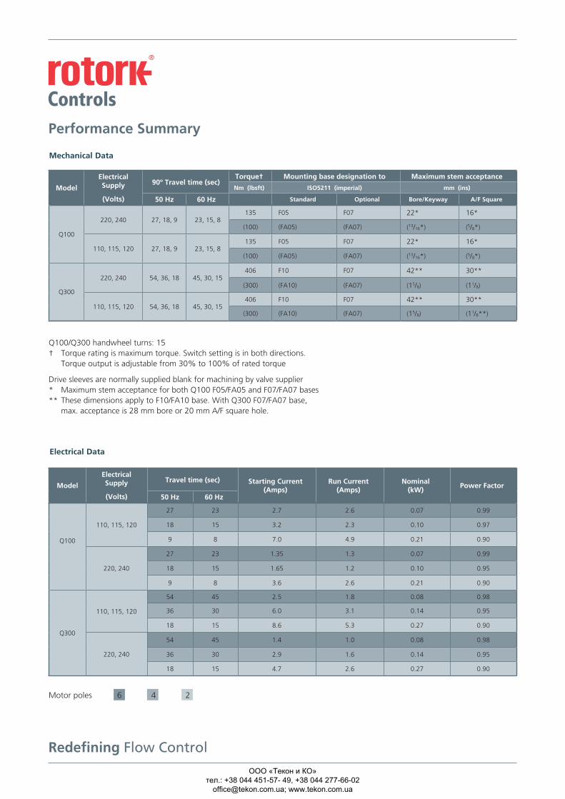
Performance Summary
Mechanical Data
Q100/Q300 handwheel turns: 15 † Torque rating is maximum torque. Switch setting is in both directions. Torque output is adjustable from 30% to 100% of rated torque
Drive sleeves are normally supplied blank for machining by valve supplier * Maximum stem acceptance for both Q100 F05/FA05 and F07/FA07 bases ** These dimensions apply to F10/FA10 base. With Q300 F07/FA07 base, max. acceptance is 28 mm bore or 20 mm A/F square hole.
Q Standard Specification Q Pak Specification
Enclosure
Watertight to IEC529, IP68 (suitable for submersion under 3 metres head of water for 48 hours) NEMA 4 and 6. Even when the terminal cover is removed, the electrical compartment is protected to a level of IP67 from ingress of dirt and moisture.
Temperature
The ‘Q’ Range has been designed for use in ambient temperatures from -30 to +70 ºC.
Vibration
The actuator can withstand plant induced vibration of 0.5g over a frequency range of 10 to 200 Hz and seismic vibration of 1g in a frequency range of 0.2 to 33 Hz. Structural integrity is maintained with a seismic vibration of up to 6g.
Performance
Output torque available from 30 lbs.ft (40 Nm).
Power Supply
The ‘Q’ Range of actuators is available as standard for use on the following single phase electrical supplies:
50 Hz-110 V, 220 V, 240 V 60 Hz-110 V, 115 V, 120 V, 127 V, 220 V and 240 V.
Other voltages can be supplied to special order. A tolerance of ±10% applies to the above voltages. The motor is S2 rated for a 20% duty cycle according to IEC 34.2.
Construction
The gearcase and all housings are diecast aluminium to BS1490. The main gearcase and motor housings are to grade LM4 with the remainder being LM24.
Output Drive
Easily removable blank, steel drive bush suitable for machining by customer to suit valve stem.
Gearing
Double reduction worm and wheel with steel worm and aluminium bronze worm wheel. The second stage worm and wheel is self locking to ensure that the output cannot be back driven by valve reaction forces.
Switches
Torque-limit and auxiliary limit switches are provided as detailed below and have the following electrical ratings on inductive loads:
110/240 VAC 15 A 110 VDC 0.25 A 50 VDC 2.5 A 24 VDC 3 A
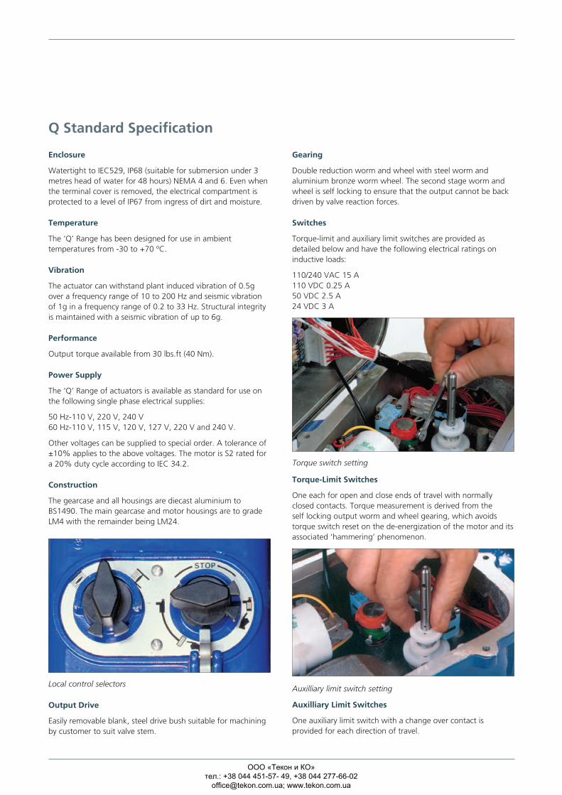
Torque-Limit Switches
One each for open and close ends of travel with normally closed contacts. Torque measurement is derived from the self locking output worm and wheel gearing, which avoids torque switch reset on the de-energization of the motor and its associated ‘hammering’ phenomenon.
Auxilliary Limit Switches
One auxiliary limit switch with a change over contact is provided for each direction of travel.
Local control selectors
Torque switch setting
Auxilliary limit switch setting
Motor
A single-phase squirrel cage capacitor run, class F insulated induction motor is fitted. The motor is protected from overload by a thermostat.
Local Indication
A mechanical, continuous position indicator is provided on the electrical compartment cover.
Mounting
All flange mountings are in accordance with ISO5211. As an alternative, they are available with UNC thread holes. See page 2.
Manual Operation
A handwheel is provided for manual operation, which is engaged by a padlockable hand/auto selection lever arranged for power preference. When engaged, the handwheel drives the second wormshaft. At no time can the handwheel be driven by the motor.
Mechanical Stops
Externally adjustable mechanical stops are provided with a setting range of 80º to 100º of output movement. The setting of these provides travel limitation for both electrical and manual operation.
Conduit Entries
Two off M32 or two off 1 inch ASA NPT.
Q-Standard – Optional Extras
Two auxiliary limit switches each independently adjustable to any pointing of valve travel.
12 watt anti-condensation heater to suit motor supply voltage. Integrally mounted open/close and local/stop/remote selectors.
1 watt potentiometer for remote valve position indication. Externally powered 4-20 mA Current Position Transmitter (CPT).
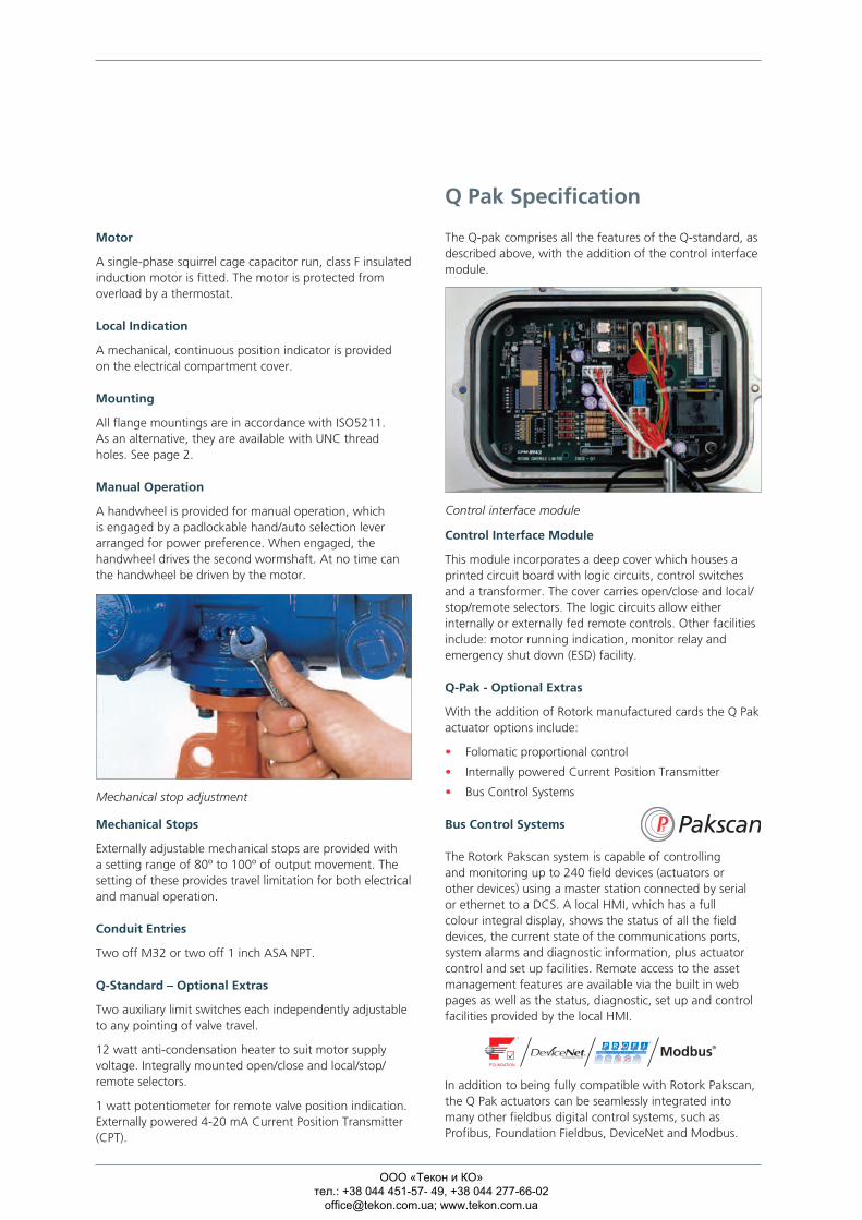
The Q-pak comprises all the features of the Q-standard, as described above, with the addition of the control interface module.
Control Interface Module
This module incorporates a deep cover which houses a printed circuit board with logic circuits, control switches and a transformer. The cover carries open/close and local/stop/remote selectors. The logic circuits allow either internally or externally fed remote controls. Other facilities include: motor running indication, monitor relay and emergency shut down (ESD) facility.
Q-Pak - Optional Extras
With the addition of Rotork manufactured cards the Q Pak actuator options include:
• Folomatic proportional control
• Internally powered Current Position Transmitter
• Bus Control Systems
Bus Control Systems
The Rotork Pakscan system is capable of controlling and monitoring up to 240 field devices (actuators or other devices) using a master station connected by serial or ethernet to a DCS. A local HMI, which has a full colour integral display, shows the status of all the field devices, the current state of the communications ports, system alarms and diagnostic information, plus actuator control and set up facilities. Remote access to the asset management features are available via the built in web pages as well as the status, diagnostic, set up and control facilities provided by the local HMI.
In addition to being fully compatible with Rotork Pakscan, the Q Pak actuators can be seamlessly integrated into many other fieldbus digital control systems, such as Profibus, Foundation Fieldbus, DeviceNet and Modbus.
Control interface module
Mechanical stop adjustment
Model
Electrical Supply
(Volts)
90º Travel time (sec)Torque† Mounting base designation to Maximum stem acceptance
Nm (lbsft) ISO5211 (imperial) mm (ins)
50 Hz 60 Hz Standard Optional Bore/Keyway A/F Square
Q100
220, 240 27, 18, 9 23, 15, 8135 F05 F07 22* 16*
(100) (FA05) (FA07) (13/16*) (5/8*)
110, 115, 120 27, 18, 9 23, 15, 8 135 F05 F07 22* 16*
(100) (FA05) (FA07) (13/16*) (5/8*)
Q300
220, 240 54, 36, 18 45, 30, 15 406 F10 F07 42** 30**
(300) (FA10) (FA07) (15/8) (11/8)
110, 115, 120 54, 36, 18 45, 30, 15 406 F10 F07 42** 30**
(300) (FA10) (FA07) (15/8) (11/8**)
Model
Electrical Supply
(Volts)
Travel time (sec) Starting Current (Amps)
Run Current (Amps)
Nominal (kW)
Power Factor
50 Hz 60 Hz
Q100
110, 115, 120
27 23 2.7 2.6 0.07 0.99
18 15 3.2 2.3 0.10 0.97
9 8 7.0 4.9 0.21 0.90
220, 240
27 23 1.35 1.3 0.07 0.99
18 15 1.65 1.2 0.10 0.95
9 8 3.6 2.6 0.21 0.90
Q300
110, 115, 120
54 45 2.5 1.8 0.08 0.98
36 30 6.0 3.1 0.14 0.95
18 15 8.6 5.3 0.27 0.90
220, 240
54 45 1.4 1.0 0.08 0.98
36 30 2.9 1.6 0.14 0.95
18 15 4.7 2.6 0.27 0.90
Electrical Data
Motor poles 6 4 2
ООО «Текон и КО» тел.: +38 044 451-57- 49, +38 044 277-66-02
[email protected]; www.tekon.com.ua
Redefining Flow Control
US A4
US
A4
A4US
US
A4
A4/US
Performance Summary
Mechanical Data
Q100/Q300 handwheel turns: 15 † Torque rating is maximum torque. Switch setting is in both directions. Torque output is adjustable from 30% to 100% of rated torque
Drive sleeves are normally supplied blank for machining by valve supplier * Maximum stem acceptance for both Q100 F05/FA05 and F07/FA07 bases ** These dimensions apply to F10/FA10 base. With Q300 F07/FA07 base, max. acceptance is 28 mm bore or 20 mm A/F square hole.
Q Standard Specification Q Pak Specification
Enclosure
Watertight to IEC529, IP68 (suitable for submersion under 3 metres head of water for 48 hours) NEMA 4 and 6. Even when the terminal cover is removed, the electrical compartment is protected to a level of IP67 from ingress of dirt and moisture.
Temperature
The ‘Q’ Range has been designed for use in ambient temperatures from -30 to +70 ºC.
Vibration
The actuator can withstand plant induced vibration of 0.5g over a frequency range of 10 to 200 Hz and seismic vibration of 1g in a frequency range of 0.2 to 33 Hz. Structural integrity is maintained with a seismic vibration of up to 6g.
Performance
Output torque available from 30 lbs.ft (40 Nm).
Power Supply
The ‘Q’ Range of actuators is available as standard for use on the following single phase electrical supplies:
50 Hz-110 V, 220 V, 240 V 60 Hz-110 V, 115 V, 120 V, 127 V, 220 V and 240 V.
Other voltages can be supplied to special order. A tolerance of ±10% applies to the above voltages. The motor is S2 rated for a 20% duty cycle according to IEC 34.2.
Construction
The gearcase and all housings are diecast aluminium to BS1490. The main gearcase and motor housings are to grade LM4 with the remainder being LM24.
Output Drive
Easily removable blank, steel drive bush suitable for machining by customer to suit valve stem.
Gearing
Double reduction worm and wheel with steel worm and aluminium bronze worm wheel. The second stage worm and wheel is self locking to ensure that the output cannot be back driven by valve reaction forces.
Switches
Torque-limit and auxiliary limit switches are provided as detailed below and have the following electrical ratings on inductive loads:
110/240 VAC 15 A 110 VDC 0.25 A 50 VDC 2.5 A 24 VDC 3 A
Torque-Limit Switches
One each for open and close ends of travel with normally closed contacts. Torque measurement is derived from the self locking output worm and wheel gearing, which avoids torque switch reset on the de-energization of the motor and its associated ‘hammering’ phenomenon.
Auxilliary Limit Switches
One auxiliary limit switch with a change over contact is provided for each direction of travel.
Local control selectors
Torque switch setting
Auxilliary limit switch setting
Motor
A single-phase squirrel cage capacitor run, class F insulated induction motor is fitted. The motor is protected from overload by a thermostat.
Local Indication
A mechanical, continuous position indicator is provided on the electrical compartment cover.
Mounting
All flange mountings are in accordance with ISO5211. As an alternative, they are available with UNC thread holes. See page 2.
Manual Operation
A handwheel is provided for manual operation, which is engaged by a padlockable hand/auto selection lever arranged for power preference. When engaged, the handwheel drives the second wormshaft. At no time can the handwheel be driven by the motor.
Mechanical Stops
Externally adjustable mechanical stops are provided with a setting range of 80º to 100º of output movement. The setting of these provides travel limitation for both electrical and manual operation.
Conduit Entries
Two off M32 or two off 1 inch ASA NPT.
Q-Standard – Optional Extras
Two auxiliary limit switches each independently adjustable to any pointing of valve travel.
12 watt anti-condensation heater to suit motor supply voltage. Integrally mounted open/close and local/stop/remote selectors.
1 watt potentiometer for remote valve position indication. Externally powered 4-20 mA Current Position Transmitter (CPT).
The Q-pak comprises all the features of the Q-standard, as described above, with the addition of the control interface module.
Control Interface Module
This module incorporates a deep cover which houses a printed circuit board with logic circuits, control switches and a transformer. The cover carries open/close and local/stop/remote selectors. The logic circuits allow either internally or externally fed remote controls. Other facilities include: motor running indication, monitor relay and emergency shut down (ESD) facility.
Q-Pak - Optional Extras
With the addition of Rotork manufactured cards the Q Pak actuator options include:
• Folomatic proportional control
• Internally powered Current Position Transmitter
• Bus Control Systems
Bus Control Systems
The Rotork Pakscan system is capable of controlling and monitoring up to 240 field devices (actuators or other devices) using a master station connected by serial or ethernet to a DCS. A local HMI, which has a full colour integral display, shows the status of all the field devices, the current state of the communications ports, system alarms and diagnostic information, plus actuator control and set up facilities. Remote access to the asset management features are available via the built in web pages as well as the status, diagnostic, set up and control facilities provided by the local HMI.
In addition to being fully compatible with Rotork Pakscan, the Q Pak actuators can be seamlessly integrated into many other fieldbus digital control systems, such as Profibus, Foundation Fieldbus, DeviceNet and Modbus.
Control interface module
Mechanical stop adjustment
Model
Electrical Supply
(Volts)
90º Travel time (sec)Torque† Mounting base designation to Maximum stem acceptance
Nm (lbsft) ISO5211 (imperial) mm (ins)
50 Hz 60 Hz Standard Optional Bore/Keyway A/F Square
Q100
220, 240 27, 18, 9 23, 15, 8135 F05 F07 22* 16*
(100) (FA05) (FA07) (13/16*) (5/8*)
110, 115, 120 27, 18, 9 23, 15, 8 135 F05 F07 22* 16*
(100) (FA05) (FA07) (13/16*) (5/8*)
Q300
220, 240 54, 36, 18 45, 30, 15 406 F10 F07 42** 30**
(300) (FA10) (FA07) (15/8) (11/8)
110, 115, 120 54, 36, 18 45, 30, 15 406 F10 F07 42** 30**
(300) (FA10) (FA07) (15/8) (11/8**)
Model
Electrical Supply
(Volts)
Travel time (sec) Starting Current (Amps)
Run Current (Amps)
Nominal (kW)
Power Factor
50 Hz 60 Hz
Q100
110, 115, 120
27 23 2.7 2.6 0.07 0.99
18 15 3.2 2.3 0.10 0.97
9 8 7.0 4.9 0.21 0.90
220, 240
27 23 1.35 1.3 0.07 0.99
18 15 1.65 1.2 0.10 0.95
9 8 3.6 2.6 0.21 0.90
Q300
110, 115, 120
54 45 2.5 1.8 0.08 0.98
36 30 6.0 3.1 0.14 0.95
18 15 8.6 5.3 0.27 0.90
220, 240
54 45 1.4 1.0 0.08 0.98
36 30 2.9 1.6 0.14 0.95
18 15 4.7 2.6 0.27 0.90
Electrical Data
Motor poles 6 4 2
ООО «Текон и КО» тел.: +38 044 451-57- 49, +38 044 277-66-02
[email protected]; www.tekon.com.ua
Redefining Flow Control
US A4
US
A4
A4US
US
A4
A4/US
Performance Summary
Mechanical Data
Q100/Q300 handwheel turns: 15† Torque rating is maximum torque. Switch setting is in both directions.
Torque output is adjustable from 30% to 100% of rated torque
Drive sleeves are normally supplied blank for machining by valve supplier* Maximum stem acceptance for both Q100 F05/FA05 and F07/FA07 bases** These dimensions apply to F10/FA10 base. With Q300 F07/FA07 base,
max. acceptance is 28 mm bore or 20 mm A/F square hole.
Q Standard Specification Q Pak Specification
Enclosure
Watertight to IEC529, IP68 (suitable for submersion under 3 metres head of water for 48 hours) NEMA 4 and 6. Even when the terminal cover is removed, the electrical compartment is protected to a level of IP67 from ingress of dirt and moisture.
Temperature
The ‘Q’ Range has been designed for use in ambient temperatures from -30 to +70 ºC.
Vibration
The actuator can withstand plant induced vibration of 0.5g over a frequency range of 10 to 200 Hz and seismic vibration of 1g in a frequency range of 0.2 to 33 Hz. Structural integrity is maintained with a seismic vibration of up to 6g.
Performance
Output torque available from 30 lbs.ft (40 Nm).
Power Supply
The ‘Q’ Range of actuators is available as standard for use on the following single phase electrical supplies:
50 Hz-110 V, 220 V, 240 V60 Hz-110 V, 115 V, 120 V, 127 V, 220 V and 240 V.
Other voltages can be supplied to special order. A tolerance of ±10% applies to the above voltages. The motor is S2 rated for a 20% duty cycle according to IEC 34.2.
Construction
The gearcase and all housings are diecast aluminium to BS1490. The main gearcase and motor housings are to grade LM4 with the remainder being LM24.
Output Drive
Easily removable blank, steel drive bush suitable for machining by customer to suit valve stem.
Gearing
Double reduction worm and wheel with steel worm and aluminium bronze worm wheel. The second stage worm and wheel is self locking to ensure that the output cannot be back driven by valve reaction forces.
Switches
Torque-limit and auxiliary limit switches are provided as detailed below and have the following electrical ratings on inductive loads:
110/240 VAC 15 A110 VDC 0.25 A50 VDC 2.5 A24 VDC 3 A
Torque-Limit Switches
One each for open and close ends of travel with normally closed contacts. Torque measurement is derived from the self locking output worm and wheel gearing, which avoids torque switch reset on the de-energization of the motor and its associated ‘hammering’ phenomenon.
Auxilliary Limit Switches
One auxiliary limit switch with a change over contact is provided for each direction of travel.
Local control selectors
Torque switch setting
Auxilliary limit switch setting
Motor
A single-phase squirrel cage capacitor run, class F insulated induction motor is fitted. The motor is protected from overload by a thermostat.
Local Indication
A mechanical, continuous position indicator is provided on the electrical compartment cover.
Mounting
All flange mountings are in accordance with ISO5211. As an alternative, they are available with UNC thread holes. See page 2.
Manual Operation
A handwheel is provided for manual operation, which is engaged by a padlockable hand/auto selection lever arranged for power preference. When engaged, the handwheel drives the second wormshaft. At no time can the handwheel be driven by the motor.
Mechanical Stops
Externally adjustable mechanical stops are provided with a setting range of 80º to 100º of output movement. The setting of these provides travel limitation for both electrical and manual operation.
Conduit Entries
Two off M32 or two off 1 inch ASA NPT.
Q-Standard – Optional Extras
Two auxiliary limit switches each independently adjustable to any pointing of valve travel.
12 watt anti-condensation heater to suit motor supply voltage. Integrally mounted open/close and local/stop/remote selectors.
1 watt potentiometer for remote valve position indication. Externally powered 4-20 mA Current Position Transmitter (CPT).
The Q-pak comprises all the features of the Q-standard, as described above, with the addition of the control interface module.
Control Interface Module
This module incorporates a deep cover which houses a printed circuit board with logic circuits, control switches and a transformer. The cover carries open/close and local/stop/remote selectors. The logic circuits allow either internally or externally fed remote controls. Other facilities include: motor running indication, monitor relay and emergency shut down (ESD) facility.
Q-Pak - Optional Extras
With the addition of Rotork manufactured cards the Q Pak actuator options include:
• Folomatic proportional control
• Internally powered Current Position Transmitter
• Bus Control Systems
Bus Control Systems
The Rotork Pakscan system is capable of controlling and monitoring up to 240 field devices (actuators or other devices) using a master station connected by serial or ethernet to a DCS. A local HMI, which has a full colour integral display, shows the status of all the field devices, the current state of the communications ports, system alarms and diagnostic information, plus actuator control and set up facilities. Remote access to the asset management features are available via the built in web pages as well as the status, diagnostic, set up and control facilities provided by the local HMI.
In addition to being fully compatible with Rotork Pakscan, the Q Pak actuators can be seamlessly integrated into many other fieldbus digital control systems, such as Profibus, Foundation Fieldbus, DeviceNet and Modbus.
Control interface module
Mechanical stop adjustment
Model
ElectricalSupply
(Volts)
90º Travel time (sec)Torque† Mounting base designation to Maximum stem acceptance
Nm (lbsft) ISO5211 (imperial) mm (ins)
50 Hz 60 Hz Standard Optional Bore/Keyway A/F Square
Q100
220, 240 27, 18, 9 23, 15, 8135 F05 F07 22* 16*
(100) (FA05) (FA07) (13/16*) (5/8*)
110, 115, 120 27, 18, 9 23, 15, 8 135 F05 F07 22* 16*
(100) (FA05) (FA07) (13/16*) (5/8*)
Q300
220, 240 54, 36, 18 45, 30, 15 406 F10 F07 42** 30**
(300) (FA10) (FA07) (15/8) (11/8)
110, 115, 120 54, 36, 18 45, 30, 15 406 F10 F07 42** 30**
(300) (FA10) (FA07) (15/8) (11/8**)
Model
ElectricalSupply
(Volts)
Travel time (sec) Starting Current(Amps)
Run Current(Amps)
Nominal(kW)
Power Factor
50 Hz 60 Hz
Q100
110, 115, 120
27 23 2.7 2.6 0.07 0.99
18 15 3.2 2.3 0.10 0.97
9 8 7.0 4.9 0.21 0.90
220, 240
27 23 1.35 1.3 0.07 0.99
18 15 1.65 1.2 0.10 0.95
9 8 3.6 2.6 0.21 0.90
Q300
110, 115, 120
54 45 2.5 1.8 0.08 0.98
36 30 6.0 3.1 0.14 0.95
18 15 8.6 5.3 0.27 0.90
220, 240
54 45 1.4 1.0 0.08 0.98
36 30 2.9 1.6 0.14 0.95
18 15 4.7 2.6 0.27 0.90
Electrical Data
Motor poles 6 4 2
ООО «Текон и КО» тел.: +38 044 451-57- 49, +38 044 277-66-02
[email protected]; www.tekon.com.ua
Redefining Flow Control
A4/US
US
A4
A4/US
US
A4
A4 US
US
A4
US
A4
A4 US
PUB007-001-00Issue 01/12
Formerly E610E. As part of a process of on-going product development, Rotork reserves the right to amend and change specifications without prior notice. Published data may be subject to change. For the very latest version release, visit our website at www.rotork.com
The name Rotork is a registered trademark. Rotork recognises all registered trademarks. Published and produced in the UK by Rotork Controls Limited. POWSH0112
www.rotork.com
A full listing of our worldwide sales and service network is available on our website.
UKRotork plctel +44 (0)1225 733200fax +44 (0)1225 333467email [email protected]
Electric Actuators and Control Systems
Fluid Power Actuators and Control Systems
Gearboxes and Gear Operators
Projects, Services and Retrofit
USARotork Controls Inc.tel +1 (585) 247 2304fax +1 (585) 247 2308email [email protected]
Watertight Single-Phase ElectricQuarter-turn Actuators for
part-turn valves and dampers
Q Range
This brochure provides a comprehensive overview of the applications and associated functions available with Rotork Q actuators - comprising Q Standard and Q Pak actuators.
The watertight ‘Q’ Range actuators have been designed using Rotork’s world proven reliability in combination with the latest technology.
They provide a simple, cost-effective way of controlling small quarter-turn valves and dampers. Designed to meet industry’s need for a compact and reliable watertight actuator where an IP68 (NEMA 6) enclosure is required. The ‘Q’ Range is a single-phase electric actuator which is available in two versions, both with the Rotork ‘double-sealed’ IP68 enclosure.
The Q-standard version is suitable for simple open/close duties where on/off control is required. This is achieved without the need for reversing contactors, giving simplified wiring. The designs of the motor and limit switch mechanism ensure combined ease of setting and reliability in use.
The Q-pak version benefits from the addition of a specially designed control interface module which enables it to operate from a wide variety of remote control signals and provides status monitoring outputs.
Watertight Single-Phase Electric Quarter-turn Actuators for part-turn valves and dampers
Q Range
Features
• Reliability of single-phase squirrel cage motors.
• Simple remote control for basic applications.
• Rugged compact double-sealed watertight enclosureproviding environmental protection during plantconstruction and cabling.
• Positive travel limitation by externally adjustablemechanical stops.
• Simple action auxiliary switch setting.
• Declutchable handwheel with padlockable hand/autoselector arranged for power preference.
• Self locking electrical and manual drive.
• Q-pak version gives compatibility with standardRotork control and monitoring configurations.
Inside the Q Range Actuator
ООО «Текон и КО»тел.: +38 044 451-57- 49, +38 044 277-66-02
[email protected]; www.tekon.com.ua