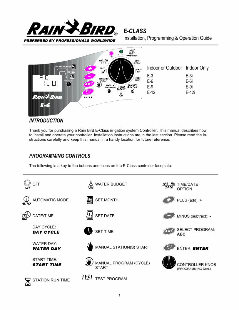
rain bird e-class user manual
TRANSCRIPT
1
2 : 0
E-CLASSInstallation, Programming & Operation Guide
PREFERRED BY PROFESSIONALS WORLDWIDE
Indoor or Outdoor
E-3E-6E-9E-12
Indoor Only
E-3iE-6iE-9iE-12i
INTRODUCTION
Thank you for purchasing a Rain Bird E-Class irrigation system Controller. This manual describes howto install and operate your controller. Installation instructions are in the last section. Please read the in-structions carefully and keep this manual in a handy location for future reference.
PROGRAMMING CONTROLS
The following is a key to the buttons and icons on the E-Class controller faceplate.
OFF
AUTOMATIC MODE
DATE/TIME
DAY CYCLE:DAY CYCLEDAY CYCLE
WATER DAY:WATER DAYWATER DAY
START TIME:START TIMESTART TIME
STATION RUN TIME
WATER BUDGET
SET MONTH
SET DATE
SET TIME
MANUAL STATION(S) START
MANUAL PROGRAM (CYCLE)START
TEST PROGRAM
TIME/DATEOPTION
PLUS (add): +
MINUS (subtract): -
SELECT PROGRAM:ABC
ENTER: ENTERENTER
CONTROLLER KNOB(PROGRAMMING DIAL)

Special Upgrade O�er
Save an extra 15% o� new sprinkler timers and irrigation controllers at the Rain Bird Online Store.*
Enter discount code:
UPGRADE15 at checkout to save an extra 15% o�*
* Additional discount not valid on clearance items, bundles or store specials. Discount applies to controller products only. Cannot be combined with
other store discount codes. Valid at the Rain Bird Online Store only. Subject to change without notice.
Still struggling with your old sprinkler timer? Having a hard time complying with local watering restrictions? Upgrading to a new Rain Bird sprinkler timer is easier than you might think.
New timers are easier to program than ever before, with powerful features to help save you time and water while keeping your yard healthy and vibrant.
There are lots of models to meet your needs, including indoor and outdoor versions, �exible modular timers and even smart controllers that automatically adjust themselves based on the weather.
Shop Now at store.rainbird.com and enjoy exclusive upgrade savings!
® Registered trademark of Rain Bird Corporation.
2
WHAT MAKES UP A PROGRAM?
DAY CYCLE: The number of days before the cycle repeats, i.e., 7-day cycle: one week long: 3-day cy-cle: once every three days.
WATERING DAYS: set weekdays ON or OFF as watering days (7-day cycle). Set "Today's" numberwithin the cycle (1 through 6-day cycles).
START TIME: The time of day that the program begins. This is the time that the first station in the pro-gram begins watering. All other stations in the program then follow in sequence, AUTOMATICALLY.
STATION RUNTIME: The number of minutes that each station runs.
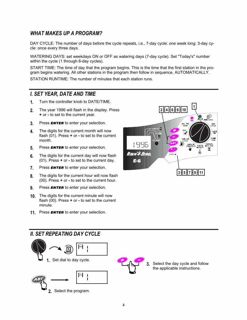
I. SET YEAR, DATE AND TIME
1. Turn the controller knob to DATE/TIME.
2. The year 1996 will flash in the display. Press+ or - to set to the current year.
3. Press ENTERENTER to enter your selection.
4. The digits for the current month will nowflash (01). Press + or - to set to the currentmonth.
5. Press ENTERENTER to enter your selection.
6. The digits for the current day will now flash(01). Press + or - to set to the current day.
7. Press ENTERENTER to enter your selection.
8. The digits for the current hour will now flash(00). Press + or - to set to the current hour.
9. Press ENTER ENTER to enter your selection.
10. The digits for the current minute will nowflash (00). Press + or - to set to the currentminute.
11. Press ENTER ENTER to enter your selection.
12 4 6 8 10
24:00
3 5 7 9 11
II. SET REPEATING DAY CYCLE
1. Set dial to day cycle.
2. Select the program.
3. Select the day cycle and followthe applicable instructions.
3
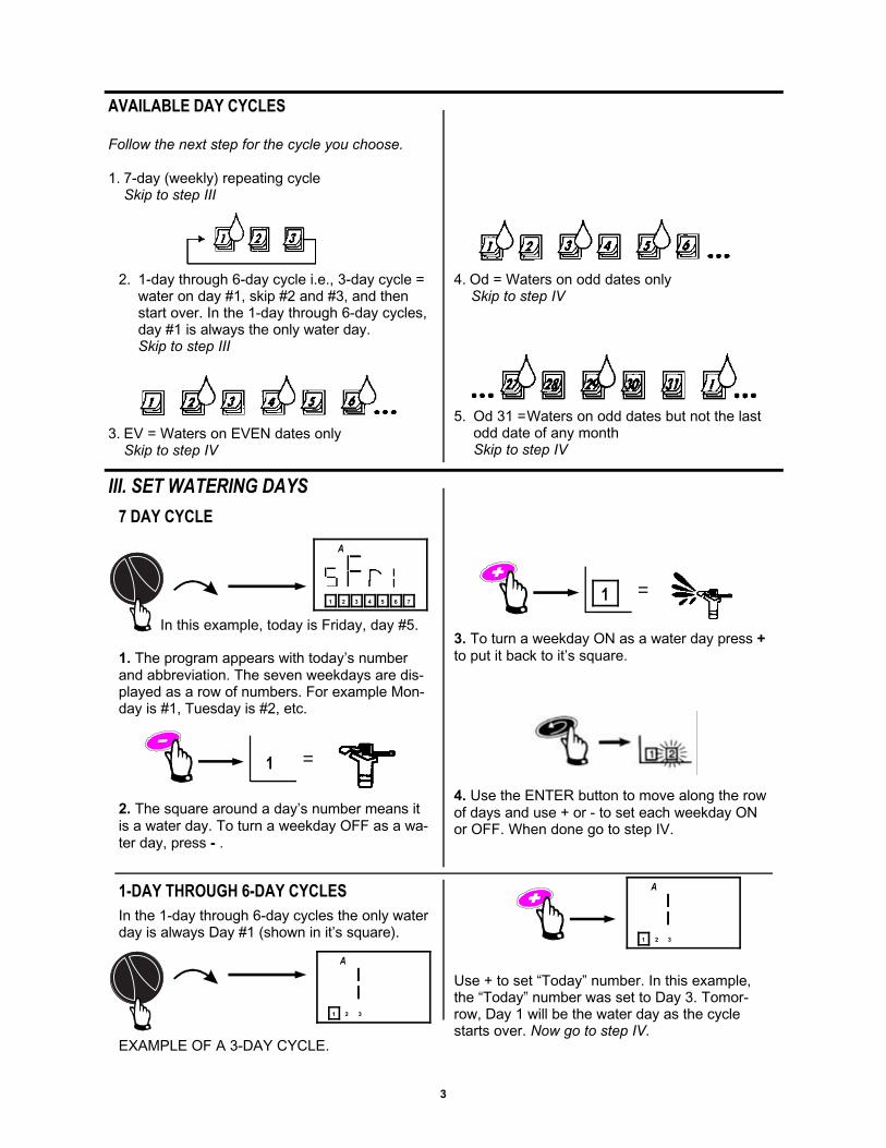
AVAILABLE DAY CYCLES
Follow the next step for the cycle you choose.
1. 7-day (weekly) repeating cycleSkip to step III
2. 1-day through 6-day cycle i.e., 3-day cycle =water on day #1, skip #2 and #3, and thenstart over. In the 1-day through 6-day cycles,day #1 is always the only water day.Skip to step III
3. EV = Waters on EVEN dates onlySkip to step IV
4. Od = Waters on odd dates onlySkip to step IV
5. Od 31 =Waters on odd dates but not the lastodd date of any monthSkip to step IV
III. SET WATERING DAYS
7 DAY CYCLE
In this example, today is Friday, day #5.
1. The program appears with today’s numberand abbreviation. The seven weekdays are dis-played as a row of numbers. For example Mon-day is #1, Tuesday is #2, etc.
1 =
2. The square around a day’s number means itis a water day. To turn a weekday OFF as a wa-ter day, press - .
1 =
3. To turn a weekday ON as a water day press +to put it back to it’s square.
4. Use the ENTER button to move along the rowof days and use + or - to set each weekday ONor OFF. When done go to step IV.
1-DAY THROUGH 6-DAY CYCLES
In the 1-day through 6-day cycles the only waterday is always Day #1 (shown in it’s square).
EXAMPLE OF A 3-DAY CYCLE.
Use + to set “Today” number. In this example,the “Today” number was set to Day 3. Tomor-row, Day 1 will be the water day as the cyclestarts over. Now go to step IV.
1 2 543 76
A
1 2 3
A
1 2 3
A
4
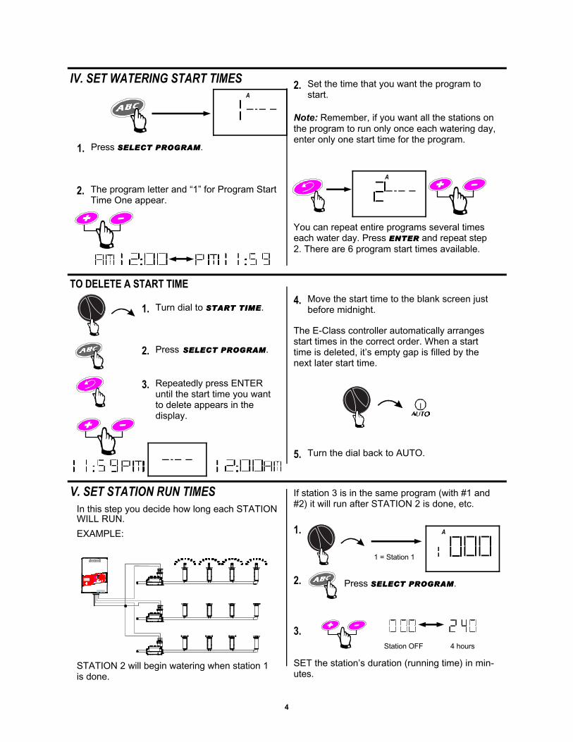
IV. SET WATERING START TIMES
2. The program letter and “1” for Program StartTime One appear.
2. Set the time that you want the program tostart.
Note: Remember, if you want all the stations onthe program to run only once each watering day,enter only one start time for the program.
TO DELETE A START TIME
1. Turn dial to START TIMESTART TIME.
2. Press SELECT PROGRAMSELECT PROGRAM.
You can repeat entire programs several timeseach water day. Press ENTERENTER and repeat step2. There are 6 program start times available.
3. Repeatedly press ENTERuntil the start time you wantto delete appears in thedisplay.
4. Move the start time to the blank screen justbefore midnight.
The E-Class controller automatically arrangesstart times in the correct order. When a starttime is deleted, it’s empty gap is filled by thenext later start time.
5. Turn the dial back to AUTO.
V. SET STATION RUN TIMES
In this step you decide how long each STATIONWILL RUN.
EXAMPLE:
STATION 2 will begin watering when station 1is done.
1.
1 = Station 1
2.
Station OFF 4 hours
If station 3 is in the same program (with #1 and#2) it will run after STATION 2 is done, etc.
SET the station’s duration (running time) in min-utes.
A
A
A
1. Press SELECT PROGRAMSELECT PROGRAM.
Press SELECT PROGRAMSELECT PROGRAM.
3.
5
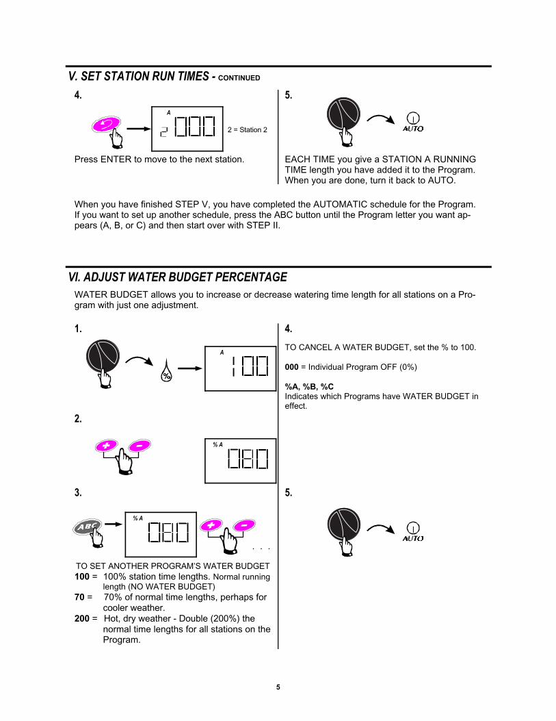
V. SET STATION RUN TIMES - CONTINUED
4.
2 = Station 2
5.
Press ENTER to move to the next station. EACH TIME you give a STATION A RUNNINGTIME length you have added it to the Program.When you are done, turn it back to AUTO.
When you have finished STEP V, you have completed the AUTOMATIC schedule for the Program.If you want to set up another schedule, press the ABC button until the Program letter you want ap-pears (A, B, or C) and then start over with STEP II.
VI. ADJUST WATER BUDGET PERCENTAGE
1.
WATER BUDGET allows you to increase or decrease watering time length for all stations on a Pro-gram with just one adjustment.
2.
3.
TO SET ANOTHER PROGRAM’S WATER BUDGET100 = 100% station time lengths. Normal running
length (NO WATER BUDGET)70 = 70% of normal time lengths, perhaps for
cooler weather.200 = Hot, dry weather - Double (200%) the
normal time lengths for all stations on theProgram.
. . .
4.
TO CANCEL A WATER BUDGET, set the % to 100.
000 = Individual Program OFF (0%)
%A, %B, %CIndicates which Programs have WATER BUDGET ineffect.
5.
A
A
% A
% A
6
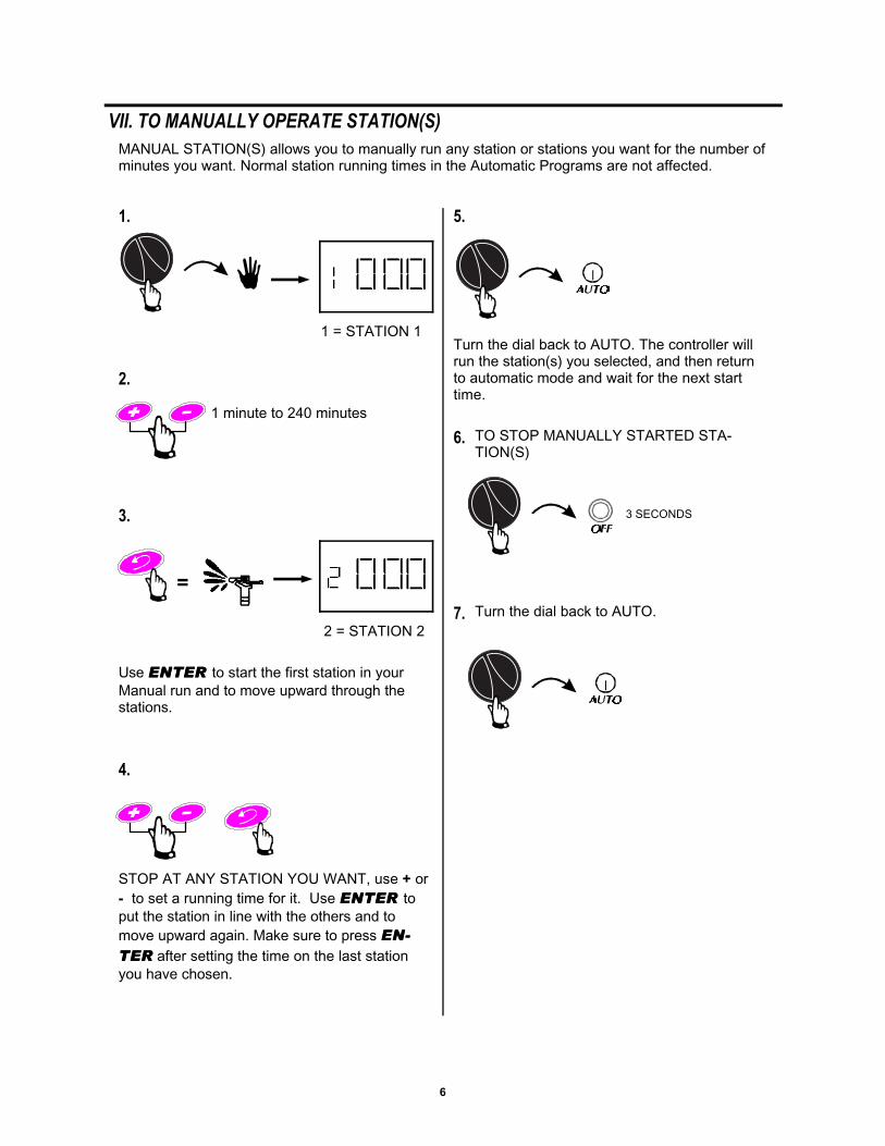
VII. TO MANUALLY OPERATE STATION(S)
1.
1 = STATION 1
2.
3.
=
5.
3 SECONDS
6. TO STOP MANUALLY STARTED STA-TION(S)
1 minute to 240 minutes
Use ENTER ENTER to start the first station in yourManual run and to move upward through thestations.
MANUAL STATION(S) allows you to manually run any station or stations you want for the number ofminutes you want. Normal station running times in the Automatic Programs are not affected.
2 = STATION 2
4.
STOP AT ANY STATION YOU WANT, use + or- to set a running time for it. Use ENTER ENTER toput the station in line with the others and tomove upward again. Make sure to press EN-EN-
TERTER after setting the time on the last stationyou have chosen.
Turn the dial back to AUTO. The controller willrun the station(s) you selected, and then returnto automatic mode and wait for the next starttime.
7. Turn the dial back to AUTO.
7
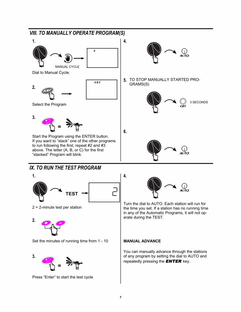
4.
VIII. TO MANUALLY OPERATE PROGRAM(S)
1.
MANUAL CYCLE
2.
3.
=
5. TO STOP MANUALLY STARTED PRO-GRAMS(S)
3 SECONDS
6.
Dial to Manual Cycle.
Select the Program
Start the Program using the ENTER button.If you want to “stack” one of the other programsto run following the first, repeat #2 and #3above. The letter (A, B, or C) for the first“stacked” Program will blink.
4.
IX. TO RUN THE TEST PROGRAM
1.
2.
3.
=
You can manually advance through the stationsof any program by setting the dial to AUTO andrepeatedly pressing the ENTER ENTER key.
2 = 2-minute test per station
Set the minutes of running time from 1 - 10
Press “Enter” to start the test cycle
TEST
Turn the dial to AUTO. Each station will run forthe time you set. If a station has no running timein any of the Automatic Programs, it will not op-erate during the TEST.
MANUAL ADVANCE
A
A B C
8
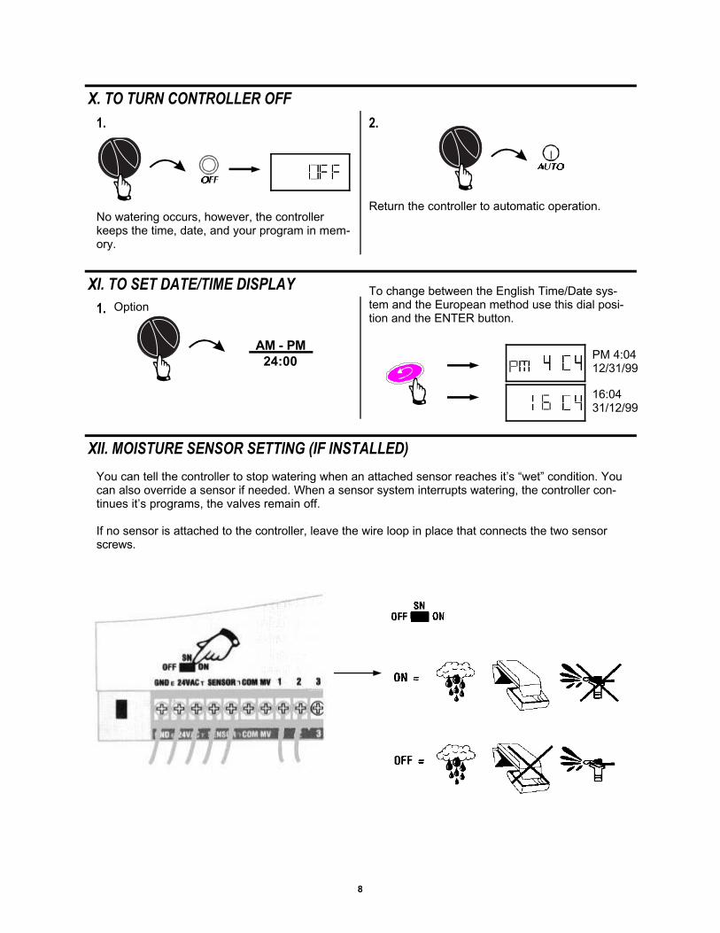
2.
X. TO TURN CONTROLLER OFF
1.
No watering occurs, however, the controllerkeeps the time, date, and your program in mem-ory.
Return the controller to automatic operation.
AM - PM24:00
XI. TO SET DATE/TIME DISPLAY
1. OptionTo change between the English Time/Date sys-tem and the European method use this dial posi-tion and the ENTER button.
XII. MOISTURE SENSOR SETTING (IF INSTALLED)
You can tell the controller to stop watering when an attached sensor reaches it’s “wet” condition. Youcan also override a sensor if needed. When a sensor system interrupts watering, the controller con-tinues it’s programs, the valves remain off.
If no sensor is attached to the controller, leave the wire loop in place that connects the two sensorscrews.
PM 4:0412/31/99
16:0431/12/99
9
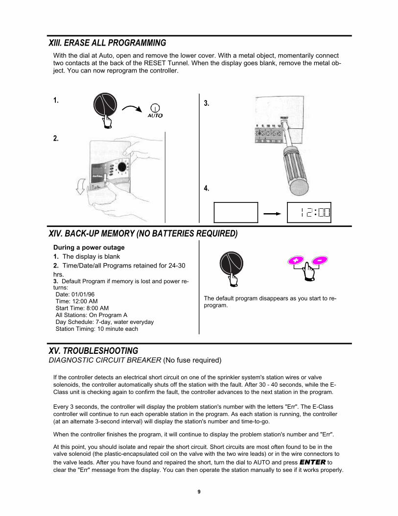
XIII. ERASE ALL PROGRAMMING
With the dial at Auto, open and remove the lower cover. With a metal object, momentarily connecttwo contacts at the back of the RESET Tunnel. When the display goes blank, remove the metal ob-ject. You can now reprogram the controller.
1.
4.
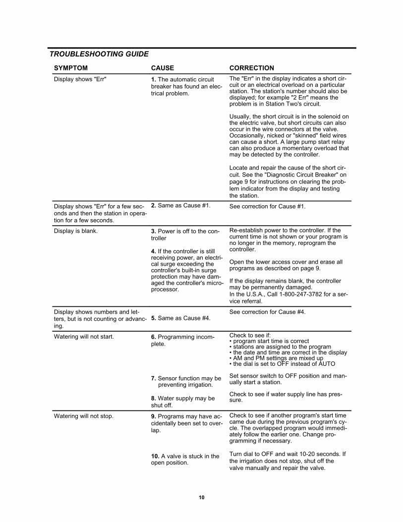
XIV. BACK-UP MEMORY (NO BATTERIES REQUIRED)
During a power outage1. The display is blank2. Time/Date/all Programs retained for 24-30hrs.3. Default Program if memory is lost and power re-turns:Date: 01/01/96Time: 12:00 AMStart Time: 8:00 AMAll Stations: On Program ADay Schedule: 7-day, water everydayStation Timing: 10 minute each
The default program disappears as you start to re-program.
XV. TROUBLESHOOTINGDIAGNOSTIC CIRCUIT BREAKER (No fuse required)
If the controller detects an electrical short circuit on one of the sprinkler system's station wires or valvesolenoids, the controller automatically shuts off the station with the fault. After 30 - 40 seconds, while the E-Class unit is checking again to confirm the fault, the controller advances to the next station in the program.
Every 3 seconds, the controller will display the problem station's number with the letters "Err". The E-Classcontroller will continue to run each operable station in the program. As each station is running, the controller(at an alternate 3-second interval) will display the station's number and time-to-go.
When the controller finishes the program, it will continue to display the problem station's number and "Err".
At this point, you should isolate and repair the short circuit. Short circuits are most often found to be in thevalve solenoid (the plastic-encapsulated coil on the valve with the two wire leads) or in the wire connectors tothe valve leads. After you have found and repaired the short, turn the dial to AUTO and press ENTERENTER toclear the "Err" message from the display. You can then operate the station manually to see if it works properly.
2.
3.
10
TROUBLESHOOTING GUIDE
SYMPTOM CAUSE CORRECTION
Display shows "Err" 1. The automatic circuitbreaker has found an elec-trical problem.
The "Err" in the display indicates a short cir-cuit or an electrical overload on a particularstation. The station's number should also bedisplayed; for example "2 Err" means theproblem is in Station Two's circuit.
Usually, the short circuit is in the solenoid onthe electric valve, but short circuits can alsooccur in the wire connectors at the valve.Occasionally, nicked or "skinned" field wirescan cause a short. A large pump start relaycan also produce a momentary overload thatmay be detected by the controller.
Locate and repair the cause of the short cir-cuit. See the "Diagnostic Circuit Breaker" onpage 9 for instructions on clearing the prob-lem indicator from the display and testingthe station.
Display shows "Err" for a few sec-onds and then the station in opera-tion for a few seconds.
2. Same as Cause #1. See correction for Cause #1.
Display is blank. 3. Power is off to the con-troller
4. If the controller is stillreceiving power, an electri-cal surge exceeding thecontroller's built-in surgeprotection may have dam-aged the controller's micro-processor.
Re-establish power to the controller. If thecurrent time is not shown or your program isno longer in the memory, reprogram thecontroller.
Open the lower access cover and erase allprograms as described on page 9.
If the display remains blank, the controllermay be permanently damaged.In the U.S.A., Call 1-800-247-3782 for a ser-vice referral.
Display shows numbers and let-ters, but is not counting or advanc-ing.
5. Same as Cause #4.See correction for Cause #4.
Watering will not start. 6. Programming incom-plete.
7. Sensor function may bepreventing irrigation.
8. Water supply may beshut off.
Check to see if:• program start time is correct• stations are assigned to the program• the date and time are correct in the display• AM and PM settings are mixed up• the dial is set to OFF instead of AUTO
Set sensor switch to OFF position and man-ually start a station.
Check to see if water supply line has pres-sure.
Watering will not stop. 9. Programs may have ac-cidentally been set to over-lap.
10. A valve is stuck in theopen position.
Check to see if another program's start timecame due during the previous program's cy-cle. The overlapped program would immedi-ately follow the earlier one. Change pro-gramming if necessary.
Turn dial to OFF and wait 10-20 seconds. Ifthe irrigation does not stop, shut off thevalve manually and repair the valve.
11
NOTE: Even though directions for connecting the wiring to the controller are provided in this manual, localelectrical codes may vary in what is required for proper and safe installation. This controller must be installedin compliance with local electrical codes
Rain Bird E-Class controllers are available in either indoor or outdoor models. Indoor models have a separatetransformer. Outdoor models have a built-in transformer and a separate plastic junction box.
CHOOSE LOCATION
Choose a mounting location near an electrical power source. For the indoor controller, the mountinglocation must be within 5' (1.5 m) of the electrical wall outlet.
For the outdoor controller, the wires from the source of electrical power to the controller need to beprotected in a conduit that meets local electrical code requirements for high voltage (either 120 or230 volt) circuits. Even though the outdoor model is housed in a weather-resistant cabinet, choose alocation that is somewhat sheltered if possible.
Note: The sliding door (cover) on the outdoor models must be left in the down (closed) position toprovide weather and water spray protection to the controller.
XVI. INSTALLING THE CONTROLLER
MOUNT CONTROLLERNote 1: Allow 7-1/2" inches of clearance above thetop of the controller (or 8-1/2" above the upper edgeof the wall mounting bracket) so you will have roomto slide the controller down over the wall mountingbracket (on models with a sliding door, this overheadclearance also allows the door to be removed or rein-stalled).
Note 2: For indoor units that do not have a slidingdoor, the overhead clearance can be reduced to 2"above the top of the controller (or 3" above the top ofthe wall mount bracket). This lower clearance may beneeded, for example, if the only mounting locationwas for the controller under a shelf on the garagewall. See note 3 on page 12 on how to mount thecontroller using this lower clearance.
1. Holding mounting bracket to the wall or othermounting surface, at about eye level, mark, with apencil, the location for screws or fasteners at the topof the narrow slot(s). For a flat surface, use keyholeslots "A" and "C" for the fasteners. If you are mount-ing the controller on a narrow post or exposed wallstud, use keyhole slot "B". The bracket's upper slotsare sized for the head of a Number 8 screw, however,you will need the type of fasteners appropriate foryour wall's surface. Remove the bracket and drive thefastener(s) into the wall where you made the marksin the upper slot(s) only. (See illustration.) DO NOTdrive a fastener through hole "D" at this time.Leave 1/4" of the fastener's shaft showing betweenthe wall and its head. Hang the wall bracket on thefasteners by the upper slot(s). Tighten or loosen thefasteners for a snug fit that will still allow the bracketto slide up and off the fasteners should it ever benecessary. With a nail or punch, tap a pilot hole inthe wall through the center of hole "D".
A B C
D
12
2. Pull upward on the slid-ing door (for controllerswith doors) to the latchedposition that exposes theface panel controls andthen with a firmer tug pullthe door upward and offthe controller. Remove thelower access cover byplacing your fingers underthe door at the bottom ofthe controller and yourthumb on top of the accessdoor on its latch hook.Then, press gently downon the latch hook andswing the door outwardand downward away fromthe controller. Turn thecontroller upside down onthe edge of a flat surface(see illustration).
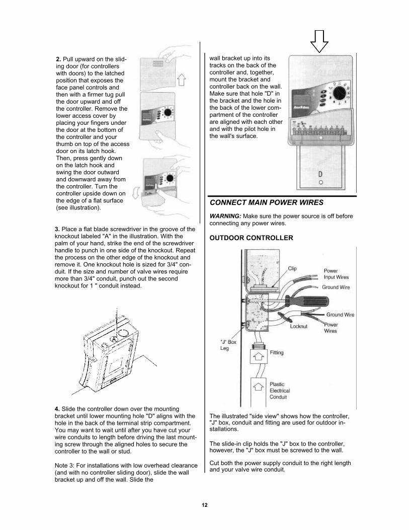
3. Place a flat blade screwdriver in the groove of theknockout labeled "A" in the illustration. With thepalm of your hand, strike the end of the screwdriverhandle to punch in one side of the knockout. Repeatthe process on the other edge of the knockout andremove it. One knockout hole is sized for 3/4" con-duit. If the size and number of valve wires requiremore than 3/4" conduit, punch out the secondknockout for 1 " conduit instead.
4. Slide the controller down over the mountingbracket until lower mounting hole "D" aligns with thehole in the back of the terminal strip compartment.You may want to wait until after you have cut yourwire conduits to length before driving the last mount-ing screw through the aligned holes to secure thecontroller to the wall or stud.
Note 3: For installations with low overhead clearance(and with no controller sliding door), slide the wallbracket up and off the wall. Slide the
wall bracket up into itstracks on the back of thecontroller and, together,mount the bracket andcontroller back on the wall.Make sure that hole "D" inthe bracket and the hole inthe back of the lower com-partment of the controllerare aligned with each otherand with the pilot hole inthe wall's surface.
CONNECT MAIN POWER WIRES
WARNING: Make sure the power source is off beforeconnecting any power wires.
OUTDOOR CONTROLLER
The illustrated "side view" shows how the controller,"J" box, conduit and fitting are used for outdoor in-stallations.
The slide-in clip holds the "J" box to the controller,however, the "J" box must be screwed to the wall.
Cut both the power supply conduit to the right lengthand your valve wire conduit.
13
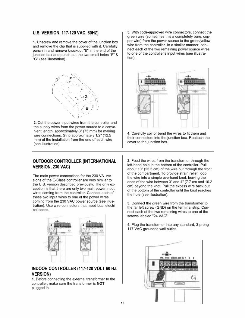
2. Feed the wires from the transformer through theleft-hand hole in the bottom of the controller. Pullabout 10" (25.5 cm) of the wire out through the frontof the compartment. To provide strain relief, loopthe wire into a simple overhand knot, leaving theends of the wire between 3" and 4" (7.7 cm and 10.2cm) beyond the knot. Pull the excess wire back outof the bottom of the controller until the knot reachesthe hole (see illustration).
3. Connect the green wire from the transformer tothe far left screw (GND) on the terminal strip. Con-nect each of the two remaining wires to one of thescrews labeled "24 VAC".
4. Plug the transformer into any standard, 3-prong117 VAC grounded wall outlet.
U.S. VERSION, 117-120 VAC, 60HZ)
1. Unscrew and remove the cover of the junction boxand remove the clip that is supplied with it. Carefullypunch in and remove knockout "E" in the end of thejunction box and punch out the two small holes "F" &"G" (see illustration).
3. With code-approved wire connectors, connect thegreen wire (sometimes this a completely bare, cop-per wire) from the power source to the green/yellowwire from the controller. In a similar manner, con-nect each of the two remaining power source wiresto one of the controller’s input wires (see illustra-tion).
4. Carefully coil or bend the wires to fit them andtheir connectors into the junction box. Reattach thecover to the junction box.
OUTDOOR CONTROLLER (INTERNATIONALVERSION, 230 VAC)
The main power connections for the 230 VA. ver-sions of the E-Class controller are very similar tothe U.S. version described previously. The only ex-ception is that there are only two main power inputwires coming from the controller. Connect each ofthese two input wires to one of the power wirescoming from the 230 VAC power source (see illus-tration). Use wire connectors that meet local electri-cal codes.
2. Cut the power input wires from the controller andthe supply wires from the power source to a conve-nient length, approximately 3" (75 mm) for makingwire connections. Strip approximately 1/2" (12.5mm) of the installation from the end of each wire(see illustration).
INDOOR CONTROLLER (117-120 VOLT 60 HZVERSION)1. Before connecting the external transformer to thecontroller, make sure the transformer is NOTplugged in.
14
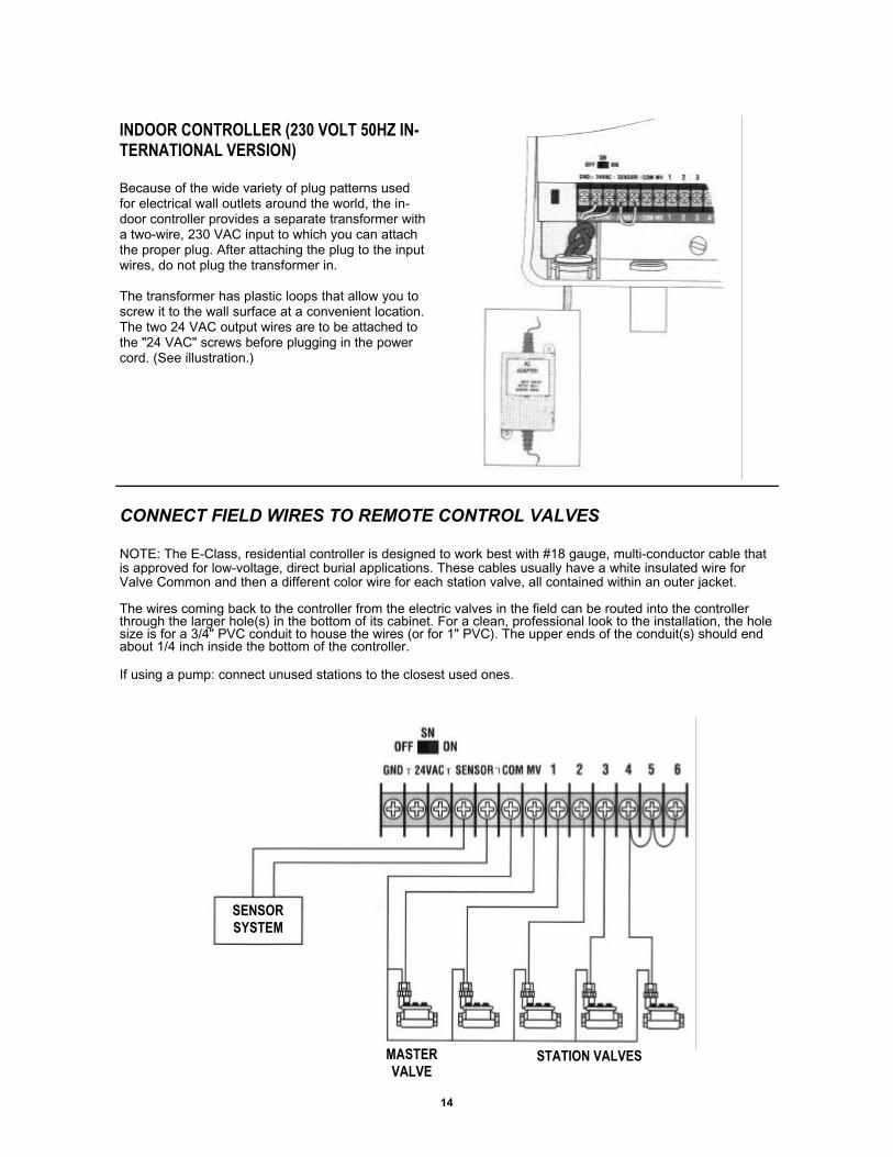
INDOOR CONTROLLER (230 VOLT 50HZ IN-TERNATIONAL VERSION)
Because of the wide variety of plug patterns usedfor electrical wall outlets around the world, the in-door controller provides a separate transformer witha two-wire, 230 VAC input to which you can attachthe proper plug. After attaching the plug to the inputwires, do not plug the transformer in.
The transformer has plastic loops that allow you toscrew it to the wall surface at a convenient location.The two 24 VAC output wires are to be attached tothe "24 VAC" screws before plugging in the powercord. (See illustration.)
CONNECT FIELD WIRES TO REMOTE CONTROL VALVES
NOTE: The E-Class, residential controller is designed to work best with #18 gauge, multi-conductor cable thatis approved for low-voltage, direct burial applications. These cables usually have a white insulated wire forValve Common and then a different color wire for each station valve, all contained within an outer jacket.
The wires coming back to the controller from the electric valves in the field can be routed into the controllerthrough the larger hole(s) in the bottom of its cabinet. For a clean, professional look to the installation, the holesize is for a 3/4" PVC conduit to house the wires (or for 1" PVC). The upper ends of the conduit(s) should endabout 1/4 inch inside the bottom of the controller.
If using a pump: connect unused stations to the closest used ones.
SENSORSYSTEM
MASTERVALVE
STATION VALVES
15
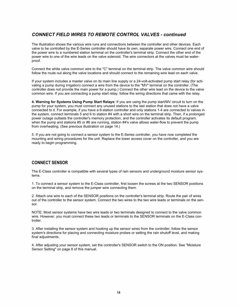
The illustration shows the various wire runs and connections between the controller and other devices. Eachvalve to be controlled by the E-Series controller should have its own, separate power wire. Connect one end ofthe power wire to a numbered station terminal on the controller's terminal strip. Connect the other end of thepower wire to one of the wire leads on the valve solenoid. The wire connectors at the valves must be water-proof.
Connect the white valve common wire to the "C" terminal on the terminal strip. The valve common wire shouldfollow the route out along the valve locations and should connect to the remaining wire lead on each valve.
If your system includes a master valve on its main line supply or a 24-volt-activated pump start relay (for acti-vating a pump during irrigation) connect a wire from the device to the "MV" terminal on the controller. (Thecontroller does not provide the main power for a pump.) Connect the other wire lead on the device to the valvecommon wire. If you are connecting a pump start relay, follow the wiring directions that came with the relay.
4. Warning for Systems Using Pump Start Relays: If you are using the pump start/MV circuit to turn on thepump for your system, you must connect any unused stations to the last station that does not have a valveconnected to it. For example, if you have a 6-station controller and only stations 1-4 are connected to valves inthe system, connect terminals 5 and 6 to station #4 with a short wire on the terminal strip. Then, if a prolongedpower outage outlasts the controller's memory protection, and the controller activates its default program,when the pump and stations #5 or #6 are running, station #4's valve allows water-flow to prevent the pumpfrom overheating. (See previous illustration on page 14.)
5. If you are not going to connect a sensor system to the E-Series controller, you have now completed themounting and wiring procedures for the unit. Replace the lower access cover on the controller, and you areready to begin programming.
CONNECT FIELD WIRES TO REMOTE CONTROL VALVES - continued
CONNECT SENSOR
The E-Class controller is compatible with several types of rain sensors and underground moisture sensor sys-tems.
1. To connect a sensor system to the E-Class controller, first loosen the screws at the two SENSOR positionson the terminal strip, and remove the jumper wire connecting them.
2. Attach one wire to each of the SENSOR positions on the controller's terminal strip. Route the pair of wiresout of the controller to the sensor system. Connect the two wires to the two wire leads or terminals on the sen-sor.
NOTE: Most sensor systems have two wire leads or two terminals designed to connect to the valve commonwire. However, you must connect these two leads or terminals to the SENSOR terminals on the E-Class con-troller.
3. After installing the sensor system and hooking up the sensor wires from the controller, follow the sensorsystem's directions for placing and connecting moisture probes or setting the rain shutoff level, and makingfinal adjustments.
4. After adjusting your sensor system, set the controller's SENSOR switch to the ON position. See "MoistureSensor Setting" on page 8 of this manual.

16
This controller generates radio frequency energy and may cause interference to radio and television reception.It has been type tested and found to comply with the limits for a Class B computing device in accordance withthe specifications in Subpart J of Part 15 of FCC Rules, which are designed to provide reasonable protectionagainst such interference in a residential installation. However, there is no guarantee that interference will notoccur in a particular installation.
If this equipment does cause interference to radio or television reception, which can be determined by turningthe equipment off and on, the user is encouraged to try to correct the interference by one or more of the follow-ing measures:
• Reorient the receiving antenna.• Move the controller away from the receiver.• Plug the controller into a different outlet so that the controller and receiver are on different branch circuits.
If necessary, the user should consult the dealer or experienced radio/ television technician for additional sug-gestions. The user may find the following booklet prepared by the Federal Communications Commission help-ful:
"How to Identify and Resolve Radio-TV Interference Problems."
This booklet is available from the U.S. Government Printing Office, Washington, D.C. 20402,Stock No. 004000003454.
PREFERRED BY PROFESSIONALS WORLDWIDE
Rain Bird Sales, Inc.Customer Support Center
6991 E. Southpoint Rd., Bldg. #1Tucson, AZ 857061-800-RAIN BIRD
(520) 434-6290 FAX© 1998 Rain Bird Sprinkler Mfg. Corp.
® Registered trademark of Rain Bird Sprinkler Mfg. Corp.
PN 633659B