radiolinx wireless specification - lesman · prosoft technology serves the automation...
TRANSCRIPT

Wireless Specifications
Radios
Switches
Antennas
Cables
Amplifiers
Lightning Protection
Accessories
June 2005
1675 Chester Avenue, 2nd Floor
Bakersfield, CA 93301
(661) 716-5100
(661) 716-5101 (Fax)

About ProSoft Technology ProSoft Technology serves the automation industry's communications and specialized application needs with high quality products, application expertise, and technical support. With our home office in Bakersfield, CA, ProSoft Technology is committed to providing localized sales and support to customers worldwide.
Sales, application engineering, and support services are provided internationally by our channels served by our Regional Area Offices:
North America Seven Regional Area Managers provide coverage for our distributors across the continent.
Latin America Two full-service offices; one services Brazil exclusively, and the other provides coverage to South America.
Europe One full-service office based in France serves Europe, Middle East, and Africa.
Asia Pacific Offices in India, China, and Malaysia service Asia, India, Australia, and New Zealand.
Company History Development of ProSoft Technology’s first product began in 1988 under contract to Allen-Bradley. This initial firmware solution provided Modbus Slave communications for the PLC platform.
Formally incorporated in 1990, by 1993 ProSoft Technology had developed an extensive protocol library which helped them evolve from a single product company to a multiple product provider. Since then, ProSoft Technology has become a major supplier of communication products for the industrial automation industry. Facilitated by our extremely active product development program and customer recognition of our product quality, ProSoft Technology now has four product families including:
In-chassis interface modules for Allen-Bradley control platforms PLC-5, SLC 500, ControlLogix, Flex I/O, CompactLogix, and SCANport/Drives.
ProLinx stand-alone industrial gateways offer communication solutions between automation platforms, controllers, field instrumentation, Ethernet, and serial networks.
In-chassis interface modules for Schneider Electric's Quantum platform.
Wireless industrial communication networks
Corporate Office: 1675 Chester Avenue, 2nd Floor Bakersfield, CA 93301 (661) 716-5100 (661) 716-5101 (Fax)
e-mail: [email protected]

Industrial Wireless Network Solutions ProSoft Technology industrial wireless modems and switches are designed to maximize network flexibility, reliability, and performance in industrial control applications. ProSoft's RadioLinx products provide a unique combination of advanced features.
RadioLinx wireless products serve Ethernet or serial applications and offer global compatibility product conformities in frequency and power. By combining RadioLinx powerful wireless connectivity with ProSoft's longstanding expertise in protocol interoperability for device and network layers, customers benefit by obtaining end-to-end industrial communications solutions and support from one source.
RadioLinx radios come with ProSoft's three-year warranty and unlimited technical support. Sales are available worldwide. Contact your automation equipment distributor or ProSoft Technology.

Contents
About ProSoft Technology .......................................................................................................... 1 Industrial Wireless Network Solutions ....................................................................................... 1
RADIOS.............................................................................................................................................. 3 RLX-IH .......................................................................................................................................... 4 RLX-FHE......................................................................................................................................... 5 RLX-FHES ...................................................................................................................................... 6 RLX-FHS......................................................................................................................................... 7 Port Layouts .................................................................................................................................. 8 Ordering Information .................................................................................................................... 9
PC SOLUTIONS............................................................................................................................... 11 RLX-PC-EB................................................................................................................................... 12 RLX-PC-IG.................................................................................................................................... 13
2.4 GHZ OMNIDIRECTIONAL ANTENNAS.................................................................................... 15 2 dBi Halfwave Antenna ............................................................................................................. 16 Tape Mount Antennas ................................................................................................................ 17 Straight Antenna ......................................................................................................................... 18 Articulating Omni Antenna ........................................................................................................ 19 Magnetic Mount........................................................................................................................... 20 Whipless Antennas..................................................................................................................... 21 Base Station Antenna................................................................................................................. 22 Heavy Duty Antenna ................................................................................................................... 24
2.4 GHZ DIRECTIONAL ANTENNAS ............................................................................................. 25 Panel/Patch Antennas ................................................................................................................ 26 Yagi Antennas ............................................................................................................................. 28 Parabolic Antennas .................................................................................................................... 30
CABLES........................................................................................................................................... 31 LMR-195 Type Cables................................................................................................................. 32

LMR-400 Type Cables................................................................................................................. 33 LMR-600 Type Cables................................................................................................................. 34 VXL5-50 Type Cables.................................................................................................................. 35 Cables ........................................................................................................................................ 36 Cable Numbering ........................................................................................................................ 37
AMPLIFIERS.................................................................................................................................... 39 RLX-500 Amplifier ....................................................................................................................... 40 RLX-500 Amplifier Kit ................................................................................................................. 41
LIGHTNING PROTECTION ............................................................................................................. 43 Lightning Protection................................................................................................................... 44
POWER DIVIDER............................................................................................................................. 45 Power Divider Kit ........................................................................................................................ 46 Ordering Information .................................................................................................................. 46

Radios
Items in this Section
• RLX-IH 4 • RLX-FHE 5 • RLX-FHES 6 • RLX-FHS 7 • Port Layouts 8 • Ordering Information 9

Radios RadioLinx Industrial Hotspot
4
RLX-IH The RadioLinx Industrial Hotspot is four times more powerful than high-speed commercial grade radios, allowing better coverage of the factory floor with fewer radios. It provides outdoor links of up to 20+ miles.
Features and Benefits Single unit repeater
functionality Powerful transmitter with
amplifier option for long range outdoor applications
Redundant master radios WPA encryption, 802.1x and MAC ID
authentication Built-in web server for browser-based
configuration and remote diagnostics Fast data throughput Compatible with any device that supports
Ethernet/IP, Modbus TCP/IP, or any 802.3 compliant Ethernet protocol
Three year standard warranty
Specifications
Radio Frequency 2400 to 2483.5 MHz (USA)* Wireless Medium Direct sequence
spread spectrum Network standard 802.11b Output power 200 mW / 500 mW**
(32 mW - Europe/Asia) Channel data rates 11, 5.5, 2, 1 Mbps Receiver sensitivity -86 dBm @ 11 Mbps
-88 dBm @ 5.5 Mbps -90 dBm @ 2 Mbps -92 dBm @ 1 Mbps
Channels (user selectable)
11 - North America 13 - Europe
Outdoor range 20 + miles at 11 Mbps Security 802.1x authentication
MAC white list WPA encryption WEP for legacy devices
Physical Enclosure Extruded aluminum with DIN
and panel mount Size 3.98” x 3.475” x 2.183”
10/100 Base-T connector, shielded RJ-45
Ethernet port
IEEE 802.3, 802.3u, 802.3x Antenna ports (2) RP-SMA connectors,
active receive diversity Weight 1.15 lbs /522g
Environmental Operating temperature
-30°C to +60°C
Humidity To 90% RH, non-condensing External power 10 to 24 VDC Average power <6W * Varies for other countries
** With external amplifier
Regulatory Approvals Type Approvals FCC FCC Part 15.247 Industry Canada RSS 210 Europe / CE LVD EN 50850-2000
RF Safety EN 50364-2001 EMC EN 301 489-1, EN 301 489-17 Spectrum EN 300 328 v1.4.1
Mexico Nom 121 SCT1 2 or 1 Australia AS/NZS 4771 Brazil 365 / 2004 e
238 / 2000 Malaysia SIRIM
Hazardous Locations UL UL 1604 Class 1 Division 2,
Groups A, B, C, D Temp Code T4A
CSA/cUL C22.2 No. 213-1987 ATEX Zone 1 ATEX I
ATEZ Zone 2 ATEX II 3 G EEx nC IIC Visit our website for the latest certification information

Radios RadioLinx Frequency Hopping Ethernet
5
RLX-FHE The RadioLinx Frequency Hopping Ethernet radio is designed to operate in high-interference environments by combining advanced frequency hopping and digital signal processing technology with outstanding receiver sensitivity and antenna diversity. This combination results in exceptional noise and interference rejection.
The RLX-FHE is compatible with all protocols that run over standard IEEE 802.3 Ethernet including TCP/IP, UDP, IPX,
NetBEUI, BootP, EtherNet/IP, and Modbus/TCP. The RLX-FHE simultaneously supports multiple 802.3 compliant protocols.
Features and Benefits Supports up to 1000 addressed devices with 2000
radios and 78 repeaters per network 64 user-selectable data channels for multiple
network operation Active antenna diversity 2.4 GHz frequency hopping spread spectrum
(FHSS) technology Secure wireless communications with data
encryption, proprietary radio protocol, and 2.4 GHz FHSS physical layer
Industrial temperature range 15+ mile range with high-gain antennas
(longer with repeaters) Remote diagnostics without interrupting data
communications Over air user programmability (after initial
configuration) using Windows-based software. Three year standard warranty
Specifications
Radio Frequency 2400 to 24835.5 MHz
(varies by country) Compliance IEEE 802.3, 802.3u, 802.3x Protocols All standard IEEE
802.3 protocols Encryption ARC4 (40 or 128 bit) Network Topology Peer-to-Peer, store and
forward repeater Hop Patterns 64 independent,
non-interfacing networks Error Detection 32-bit CRC and ARQ
(Automatic Re-Send Query) Radio Type Frequency Hopping
Spread Spectrum Output power 1mW to 250mW,
programmable (varies by country)
Channel data rates 250 Kbps Receiver sensitivity -96 dBm @ 10-6 BER Channels - user selectable
64 North America (varies by country)
Typical indoor range
500 to 1500 ft (150 to 450 meters)
Outdoor range 15 + miles line of site with high-gain antennas
Security ARC4 (40 or 128 bit)
Physical Enclosure Extruded aluminum with DIN
and panel mount Size 4.10” x 3.71” x 2.05”
(104.1 mm x 94.23 mm x 52.07 mm) 10/100 Base-T connector, shielded RJ-45
Ethernet port
IEEE 802.3, 802.3u, 802.3x Weight 1 lbs /454g
Environmental Operating temperature
-40°C to +70°C (-40° F to 158° F)
Humidity To 90% RH, non-condensing External power 10 to 24 VDC Average power <4W
Regulatory Approvals Type Approvals FCC FCC Part 15.247 Industry Canada RSS 210 Europe / CE LVD EN 50850-2000
RF Safety EN 50364-2001 EMC EN 301 489-1, EN 301 489-17 Spectrum EN 300 328 v1.4.1
Mexico Nom 121 SCT1 2 or 1 Australia AS/NZS 4771 Brazil 365 / 2004 e
238 / 2000 Malaysia SIRIM
Hazardous Locations UL UL 1604 Class 1 Division 2,
Groups A, B, C, D Temp Code T4A
CSA/cUL C22.2 No. 213-1987 ATEZ Zone 2 ATEX II 3 G EEx nC IIC Visit our website for the latest certification information

Radios RadioLinx Frequency Hopping Ethernet with Serial Device Server
6
RLX-FHES The RadioLinx Frequency Hopping Ethernet with Serial Device Server contains an embedded serial device server that enables a transparent connection between an Ethernet host and a serial only device connected to the RLX-FHES RS-232 serial port. Several serial protocols are supported including DF1, ASCII, DNP3, and Modbus RTU.
Encapsulated serial or Modbus/TCP Ethernet packets
are delivered to the RLX-FHES socket where the serial server extracts the serial data stream from the Ethernet packets and outputs it to the RS-232 port. Bi-directional serial communication is supported by encapsulating the RS-232 port input stream into Ethernet packets, then sending them to the host client via the established socket interface.
Features and Benefits Supports up to 1000 addressed devices with 2000
radios and 78 repeaters per network 64 user-selectable data channels for multiple
network operation Full-Duplex asynchronous communication rates to
100 Kbps Active antenna diversity 2.4 GHz frequency hopping spread spectrum
(FHSS) technology Secure wireless communications with data
encryption, proprietary radio protocol, and 2.4 GHz FHSS physical layer
Industrial temperature range 15+ mile range with high-gain antennas
(longer with repeaters) Remote diagnostics without interrupting data
communications Over air user programmability (after initial
configuration) using Windows-based software Three year standard warranty
Specifications
Radio Frequency 2400 to 2483.5 MHz
(varies by country) Compliance IEEE 802.3, 802.3u, 802.3x Protocols All standard IEEE
802.3 protocols Encryption ARC4 (40 or 128 bit) Network Topology Peer-to-Peer, store and
forward repeater Hop Patterns 64 independent,
non-interfacing networks Error Detection 32-bit CRC and ARQ
(Automatic Re-Send Query) Radio Type Frequency Hopping
Spread Spectrum Output power 1mW to 250mW,
programmable (varies by country)
Channel data rates 250 Kbps
Receiver sensitivity -96 dBm @ 10-6 BER Channels - user selectable
79 North America (varies by country)
Typical indoor range
500 to 1500 ft (150 to 450 meters)
Outdoor range 15 + miles line of site with high-gain antennas
Security ARC4 (40 or 128 bit)
Physical Enclosure Extruded aluminum with DIN
and panel mount Size 4.10” x 3.71” x 2.05”
(104.1 mm x 94.23 mm x 52.07 mm)
Serial Data Port RS-232, DB9 Asynchronous half-duplex/full-duplex 2400 bps to 115.2 Kbps full duplex 10/100 Base-T connector, shielded RJ-45
Ethernet port
IEEE 802.3, 802.3u, 802.3x Antenna ports (2) RP-SMA connectors,
automatic antenna diversity Weight 1 lbs /454g
Environmental Operating temperature
-40°C to +70°C (-40° F to 158° F)
Humidity To 90% RH, non-condensing External power 10 to 24 VDC Average power <4W
Regulatory Approvals Type Approvals FCC FCC Part 15.247 Industry Canada RSS 210 Europe / CE LVD EN 50850-2000
RF Safety EN 50364-2001 EMC EN 301 489-1, EN 301 489-17 Spectrum EN 300 328 v1.4.1
Mexico Nom 121 SCT1 2 or 1 Australia AS/NZS 4771 Brazil 365 / 2004 e
238 / 2000 Malaysia SIRIM
Hazardous Locations UL UL 1604 Class 1 Division 2,
Groups A, B, C, D Temp Code T4A
CSA/cUL C22.2 No. 213-1987 ATEZ Zone 2 ATEX II 3 G EEx nC IIC Visit our website for the latest certification information
Radios RadioLinx Frequency Hopping Serial
7
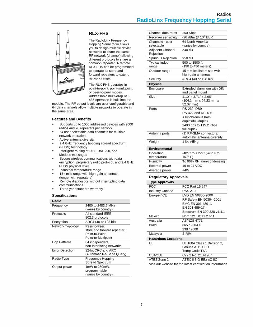
RLX-FHS The RadioLinx Frequency Hopping Serial radio allows you to design multiple device networks to share the same RF network (channel) allowing different protocols to share a common repeater. A remote RLX-FHS can be programmed to operate as store and forward repeaters to extend network range.
The RLX-FHS operates in point-to-point, point-multipoint, or peer-to-peer modes. Addressable multi-drop RS-485 operation is built into the
module. The RF output levels are user-configurable and 64 data channels allow multiple networks to operate in the same area.
Features and Benefits Supports up to 1000 addressed devices with 2000
radios and 78 repeaters per network 64 user-selectable data channels for multiple
network operation Active antenna diversity 2.4 GHz frequency hopping spread spectrum
(FHSS) technology Intelligent routing of DF1, DNP 3.0, and
Modbus messages Secure wireless communications with data
encryption, proprietary radio protocol, and 2.4 GHz FHSS physical layer
Industrial temperature range 15+ mile range with high-gain antennas
(longer with repeaters) Remote diagnostics without interrupting data
communications Three year standard warranty
Specifications
Radio Frequency 2400 to 2483.5 MHz
(varies by country) Protocols All standard IEEE
802.3 protocols Encryption ARC4 (40 or 128 bit) Network Topology Peer-to-Peer,
store and forward repeater, Point-to-Point, Point-to-Multipoint
Hop Patterns 64 independent, non-interfacing networks
Error Detection 32-bit CRC and ARQ (Automatic Re-Send Query)
Radio Type Frequency Hopping Spread Spectrum
Output power 1mW to 250mW, programmable (varies by country)
Channel data rates 250 Kbps Receiver sensitivity -96 dBm @ 10-6 BER Channels - user selectable
64 North America (varies by country)
Adjacent Channel Rejection
>40 dB
Spurious Rejection >50 dB Typical indoor range
500 to 1500 ft (150 to 450 meters)
Outdoor range 15 + miles line of site with high-gain antennas
Security ARC4 (40 or 128 bit)
Physical Enclosure Extruded aluminum with DIN
and panel mount Size 4.10” x 3.71” x 2.05”
(104.1 mm x 94.23 mm x 52.07 mm)
Ports RS-232, DB9 RS-422 and RS-485 Asynchronous half-duplex/full-duplex 2400 bps to 115.2 Kbps full duplex
Antenna ports (2) RP-SMA connectors, automatic antenna diversity
Weight 1 lbs /454g
Environmental Operating temperature
-40°C to +75°C (-40° F to 167° F)
Humidity To 90% RH, non-condensing External power 10 to 24 VDC Average power <4W
Regulatory Approvals Type Approvals FCC FCC Part 15.247 Industry Canada RSS 210 Europe / CE LVD EN 50850-2000
RF Safety EN 50364-2001 EMC EN 301 489-1, EN 301 489-17 Spectrum EN 300 328 v1.4.1
Mexico Nom 121 SCT1 2 or 1 Australia AS/NZS 4771 Brazil 365 / 2004 e
238 / 2000 Malaysia SIRIM
Hazardous Locations UL UL 1604 Class 1 Division 2,
Groups A, B, C, D Temp Code T4A
CSA/cUL C22.2 No. 213-1987 ATEZ Zone 2 ATEX II 3 G EEx nC IIC Visit our website for the latest certification information

Radios RadioLinx Frequency Hopping Serial
8
Port Layouts Top Ports All three FH radios share the same top port configuration
FH Radios
IH Radio
Bottom Ports The FHE and FHES radios share the same bottom port configuration.
FHE and FHES
FHS
IH

Radios Ordering Information
9
Ordering Information The following Ordering Information should be used to identify the radio product needed for your region. If you are unsure which radio to select, please contact your local distributor.
RadioLinx 2.4 GHz Wireless Ethernet Switches Country Catalog # Frequency RF Power Power Supply Australia RLX-FHE-AU 2400-2483.5 MHz 4W AU China RLX-FHE-CN 2400-2483.5 MHz 500 mW EIRP EU Europe RLX-FHE-EU 2400-2483.5 MHz 100 mW EIRP EU France RLX-FHE-FR 2400-2454 MHz 100 mW EIRP EU Mexico RLX-FHE-MX 2450-2483.5 MHz 650 mW EIRP US Saudi Arabia RLX-FHE-SA 2413-2439 MHz 100 mW EIRP US Singapore RLX-FHE-SG 2400-2483.5 MHz 100 mW EIRP UK United Kingdom RLX-FHE-UK 2400-2483.5 MHz 100 mW EIRP UK USA RLX-FHE-US 2400-2483.5 MHz 4W US
RadioLinx 2.4 GHz Frequency Hopping Ethernet Switch with Serial Server Country Catalog # Frequency RF Power Power Supply Australia RLX-FHES-AU 2400-2483.5 MHz 4W AU China RLX-FHES-CN 2400-2483.5 MHz 500 mW EIRP EU Europe RLX-FHES-EU 2400-2483.5 MHz 100 mW EIRP EU France RLX-FHES-FR 2400-2454 MHz 100 mW EIRP EU Mexico RLX-FHES-MX 2450-2483.5 MHz 650 mW EIRP US Saudi Arabia RLX-FHES-SA 2413-2439 MHz 100 mW EIRP US Singapore RLX-FHES-SG 2400-2483.5 MHz 100 mW EIRP UK United Kingdom RLX-FHES-UK 2400-2483.5 MHz 100 mW EIRP UK USA RLX-FHES-US 2400-2483.5 MHz 4W US
RadioLinx 2.4GHz Frequency Hopping Serial Modem Country Catalog # Frequency RF Power Power Supply Australia RLX-FHS-AU 2400-2483.5 MHz 4W AU China RLX-FHS-CN 2400-2483.5 MHz 500 mW EIRP EU Europe RLX-FHS-EU 2400-2483.5 MHz 100 mW EIRP EU France RLX-FHS-FR 2400-2454 MHz 100 mW EIRP EU Mexico RLX-FHS-MX 2450-2483.5 MHz 650 mW EIRP US Saudi Arabia RLX-FHS-SA 2413-2439 MHz 100 mW EIRP US Singapore RLX-FHS-SG 2400-2483.5 MHz 100 mW EIRP UK United Kingdom RLX-FHS-UK 2400-2483.5 MHz 100 mW EIRP UK USA RLX-FHS-US 2400-2483.5 MHz 4W US
RadioLinx 2.4 GHz Industrial Hotspot Country Catalog # Frequency RF Power Power Supply Australia RLX-IH-AU 2400-2483.5 MHz 4W AU China RLX-IH-CN 2400-2483.5 MHz 500 mW EIRP EU Europe RLX-IH-EU 2400-2483.5 MHz 100 mW EIRP EU France RLX-IH-FR 2400-2454 MHz 100 mW EIRP EU Mexico RLX-IH-MX 2450-2483.5 MHz 650 mW EIRP US Saudi Arabia RLX-IH-SA 2413-2439 MHz 100 mW EIRP US Singapore RLX-IH-SG 2400-2483.5 MHz 100 mW EIRP UK United Kingdom RLX-IH-UK 2400-2483.5 MHz 100 mW EIRP UK USA RLX-IH-US 2400-2483.5 MHz 4W US

PC Solutions Wireless radio cards for use in a laptop computer.
Items in this Section
• RLX-PC-EB 12 • RLX-PC-IG 13

PC Solutions Industrial Wireless PC Card with External Antenna
12
RLX-PC-EB
The RadioLinx Industrial Wireless PC Card with External Antenna is an ultra-fast wireless solution for the most demanding industrial applications. While providing the benefits of industrial wireless Ethernet connectivity for fixed or mobile devices with 10/100 Base-T Ethernet connections, the RLX-PC-EB is a high-power client radio for the “industrial hotspot” RLX-IH and other wireless access devices.
Features and Benefits Up to 23 dBm transmit output power providing up
to eight times more power than commercial grade PC cards.
IEEE 802.11b compliant Automatic data rate scaling at 11, 5.5, 2,
and 1 Mbps Improved 64/128-bit WEP Engine Wide coverage range up to 1200 meters in
open space Advanced Power Management and extended
battery life Plug and Play installation Improved indoor multi-path distortion provides
higher link quality in indoor environments
Specifications
General Radio Data Rate 11, 5.5, 2, and 1 Mbps, Auto
Fall-Back Range (open environment) @23 dBm
11 Mbps - 300m/450m 5.5 Mbps - 400m/600m 2 Mbps - 500m/750m 1 Mbps - 800m/1200m
Operating Voltage 3.3V/5V Compatibility Fully interoperable with
IEEE802.11b compliant products
LED Indicator RF Link Activity Network Architecture
Support ad-hoc, peer-to-peer networks, and infrastructure communications to wired Ethernet networks via Access Point
Drivers Windows 98/ME/2000/NT 4.0/CE/XP
Access Protocol CSMS/CA Roaming IEEE802.11b compliant Security 64/128-bit WEP data
encryption Frequency Band 2.4 to 2.484 GHz Radio Type Direct Sequence Spread
Spectrum (DSSS)
Modulation CCK (11, 5.5 Mbps), DQPSK (2 Mbps), DBPSK (1 Mbps)
Operation Channels
11 for North America, 14 for Japan, 13 for Europe, 2 for Spain, and 4 for France
RF Output Power 23 dBm (200mW) - FCC 20dBm (100mW) - CE
Antenna Two antenna connectors (MMCX)
Sensitivity @ FER=0.08
89dBm @ 11Mbps 91dBm @ 5.5Mbps 93dBm @ 2Mbps 95dBm @ 1Mbps
Physical Form Factor PCMCIA Type II PC Card Size 118 (L) mm x 54 (W) mm x
7.5 (H) mm Weight 40 g
Environmental Temperature Range
-10° C to 60° C Operating -40° C to 70° C Storage
Humidity 5% to 95% typical
Regulatory Approvals Type Approvals FCC FCC Part 15/UL ETSI ETSI 300/328/CE
Ordering Information RLX-PC-EB 802.11b PC Radio Card with
external antenna plug

PC Solutions Industrial Wireless PC Card with Internal Antenna
13
RLX-PC-IG
The RadioLinx Industrial Wireless PC Card with Internal Antenna is an ultra-fast wireless solution for the most demanding industrial applications. While providing the benefits of industrial wireless Ethernet connectivity for fixed or mobile devices with 10/100 Base-T Ethernet connections, the RLX-PC-IG is a high-power client radio for the “industrial hotspot” RLX-IH and other wireless access devices.
Features and Benefits Up to 21 dBm transmit output power providing up
to four times the transmit power of commercial grade wireless cards
IEEE 802.11b and IEEE 802.11g compliant Automatic data rate scaling at up to 54 Mbps Wi-Fi Protected Access (WPA) with Pre-Shared
Key (PSK) (requires driver update) 802.11d global regulatory roaming
Specifications
General Radio Data Rate 1, 2, 5.5, 6, 9, 11, 12, 18, 24,
36, 48, and 54 Mbps Operating Voltage 3.3V/5V Compatibility Fully interoperable with
IEEE802.11b & IEEE802.11g compliant products
LED Indicator RF Link Activity Network Architecture
Support ad-hoc, peer-to-peer networks, and infrastructure communications to wired Ethernet networks via Access Point
Drivers Windows 98/ME/2000/NT 4.0/CE/XP
Access Protocol CSMS/CA Security Wi-Fi Protected Access
(WPA) Frequency Band 2.12 to 2.484 GHz
Radio Type Direct Sequence Spread Spectrum (DSSS)
Modulation CCK (11, 5.5 Mbps), DQPSK (2 Mbps), DBPSK (1 Mbps), BPSK (6, 9 Mbps), QPSK (12, 18 Mbps), 16-QAM (24, 36 Mbps), 64-QAM (48, 54 Mbps)
Operation Channels
11 for North America, 13 for Europe, 2 for Spain, and 4 for France
RF Output Power FCC < 23 dBm (200mW) @ 1, 2, 5.5, 11 Mbps <22 dBm (158 mW) @ 6, 9, 12, 18 Mbps < 19 dBm (79 mW) @ 24, 26 Mbps < 18 dBm (63 mW) @ 48, 54 Mbps CE 20dBm (100mW) Power depends on country regulations
Antenna Integrated with built-in diversity
Receive @ typical -92 dBm @ 1 Mbps -89 dBm @ 2 Mbps -88 dBm @ 5.5 Mbps -91 dBm @ 6 Mbps -90 dBm @ 9 Mbps -85 dBm @ 11 Mbps -87 dBm @ 12 Mbps -85 dBm @ 18 Mbps -82 dBm @ 24 Mbps -78 dBm @ 36 Mbps -71 dBm @ 48 Mbps
Physical Form Factor PCMCIA Type II PC Card Size 118 (L) mm x 54 (W) mm x
7.5 (H) mm Weight 40 g
Environmental Temperature Range
0° C to 55° C Operating -40° C to 70° C Storage
Humidity 5% to 95% typical
Regulatory Approvals Type Approvals FCC FCC Part 15/UL ETSI ETSI 300/328/CE
Ordering Information RLX-PC-IG 802.11g PC Radio Card with
internal antenna

2.4 GHz Omnidirectional Antennas All antennas in this section have been tested for compatibility with RadioLinx products. Please see our Antenna Selection Guide to assist you in choosing the best antenna for your application.
Items in this Section
• 2 dBi Halfwave Antenna 16 • Tape Mount Antennas 17 • Straight Antenna 18 • Articulating Omni Antenna 19 • Magnetic Mount 20 • Whipless Antennas 21 • Base Station Antenna 22 • Heavy Duty Antenna 24

2.4 GHz Omnidirectional Antennas Halfwave Antenna
16
2 dBi Halfwave Antenna The Halfwave Antenna is molded in polyurethane with a reverse polarity SMA connector.
Features and Benefits Halfwave design does note require a
groundplane. Rugged injection molded design exceeds
stringent OEM drop test requirements.
Ordering Information A2402S-OSLP 2 dBi Omnicollinear Antenna
General Specifications Radome Material
Flexible Urethane Exterior (molded)
Polarization Vertical Nominal Impedance
50 Ohms
Termination Type RP-SMA plug Height 2.5”
Electrical Specifications Model # Frequency Range Gain Bandwidth VSWR A2402S-OSLP 2400-2500 MHz 2 dBi 75 MHz 1.5:1

2.4 GHz Omnidirectional Antennas Tape Mount Antennas
17
Tape Mount Antennas The RadioLinx Tape Mount Antennas have a VSWR of less than 1.5:1. These rugged antennas accommodate a wide variety of applications including office LAN environments, factories, remote telemetry, and other harsh environments where a compact, stick-on mount antenna solution is required. The antennas utilize 3M® very high bond tape for quick, easy mounting.
Features and Benefits High bond tape mount provides mounting flexibility
for various applications, including computer monitors, hand-held devices, cashier terminals, glass, and so on.
Rugged, ultra thin housing design withstands heavy use and provides maximum visibility.
The antennas can be used for fixed or mobile applications providing maximum flexibility and versatility.
Desktop base mount included which is ideal for use in office and home environments.
Antennas are provided in kits that include the antenna with a 72 inch pigtail that can be fitted with various connector types, and a base.
Ordering Information A2402S-OTM 2 dBi Omnidirectional Tape Mount
Antenna
General Specifications Radome Material
U.V. resistant pultruded fiberglass
Polarization Vertical, linear Nominal Impedance
50 Ohms
Mounting Method
3M® high bond tape Desktop base mount included in black
Termination Type RP-SMA plug with LMR 100A 72” pigtail
Electrical Specifications Model # Frequency Range Gain VSWR Max Power Color A2402S-OTM 2400-2500 MHz 2 dBi <1.7:1 on glass, <2:1 in free space 5 W Black
Mechanical Specifications Model # Temperature Range Cable Dimensions Weight A2402S-OTM 40° C to +85° C 72” (1,828.8 mm)
LMR100A 5.7” L x 1” W x 0.1” D (144.8 x 25.4 x 2.54 mm)
0.14 lbs (0.064 kg)
Patterns A2402S-OTM Elevation A2402S-OTM Azimuth

2.4 GHz Omnidirectional Antennas Straight Antenna
18
Straight Antenna The Straight Antenna works well with belt-mounted remote radios and is available in two models.
Ordering Information A2402S-OS 2 dBi Omnicollinear Antenna A2405S-OS 5 dBi Omnicollinear Antenna
General Specifications Radome Material
Flexible Urethane Exterior (molded)
Connector Material
Brass with black chrome plating
Polarization Vertical Nominal Impedance
50 Ohms
Termination Type RP-SMA plug Height 2.5”
Electrical Specifications Model # Frequency Range Gain A2402S-OS 2400-2500 MHz 2 dBi A2405S-OS 2400-2483.5 MHz 5 dBi
Mechanical Specifications Model # Height Weight Operation Temp Storage Temp A2402S-OS 4.1” (104 mm) 0.34 lbs (0.172 kg) -20 to +65 celsius -30 to +75 celsius A2405S-OS 7.1” (180 mm) 0.38 lbs (0.172 kg) -20 to +65 celsius -30 to +75 celsius
Patterns A2402S-OS Elevation A2405S-OS Elevation
A2402S-OS Azimuth A2405S-OS Azimuth

2.4 GHz Omnidirectional Antennas Articulating Omni Antenna
19
Articulating Omni Antenna The Articulating Omni Antenna bends at the connection and is typically connected to a remote radio.
Ordering Information A2405S-OA 5 dBi Omnicollinear Antenna
General Specifications Radome Material
Flexible Urethane Exterior (molded)
Connector Material
Brass with black chrome plating
Polarization Vertical Nominal Impedance
50 Ohms
Termination Type RP-SMA plug Height 2.5”
Electrical Specifications Model # Frequency Range Gain A2405S-OA 2400-2500 MHz 5 dBi
Mechanical Specifications Model # VSWR Height Operation Temp Storage Temp A2405S-OA <2.0:1 6.5” (166 mm) -20 to +65 celsius -30 to +75 celsius
Patterns A2405S-OA Elevation A2405S-OA Azimuth

2.4 GHz Omnidirectional Antennas Magnetic Mount Omnicollinear Antenna
20
Magnetic Mount The engineered design of the Magnetic Mount Omnicollinear Antenna combines a magnetic base, an antenna whip and high efficiency cable that allows direct installation on metallic surfaces without the need to use a separate antenna mount.
Features and Benefits Black coated whip assembly and machine
polymer base. Inconspicuous appearance, less susceptible to theft or vandalism.
High efficiency cable provides maximum power to the antenna to help optimize system performance.
Ordering Information A2405S-OM 5 dBi Omnicollinear Magnetic
Mount Antenna
General Specifications Radome Material
Stainless steel with black chrome finish
Polarization Vertical Nominal Impedance
50 Ohms
Mounting Method
Magnetic Base
Termination Type RP-SMA plug on 72" pigtail
Electrical Specifications Model # Frequency Range Gain VSWR Max Power A2405S-OM 2400-2484 MHz 5 dBi <1.5:1 15 W
Mechanical Specifications Model # Height Weight Operation Temp Rod/Coil Type A2405S-OM 9” (228.6 mm) 2.5 oz -40 to +70 celsius Trilinear/open
Patterns A2405S-OM Elevation A2405S-OM Azimuth

2.4 GHz Omnidirectional Antennas A2403NBH-OC Whipless Antenna
21
Whipless Antennas The RadioLinx A2403NBH-OC Whipless Antenna is a tough antenna for outdoor or indoor applications. The revolutionary design features field diversity with both vertical and horizontal polarization components. This provides the antenna
diversity, frequency agility, low visibility, wide bandwidth, wide bandwidth, and a low angle radiation pattern that is superior to traditional gain antennas in most applications.
Features and Benefits Excellent for voice to telemetry applications Permanent mounting. Permanent mount models
are available for high-risk applications such as metering where antennas must resist vandalism and achieve economical mounting
The patented whipless design allows car washes without removing the antenna. Whipless means they don't look like antennas, attract less attention, less vandalism, and have lower wind resistance. The A2403NBH-OC is also less susceptible to damage by trees, garages, or other obstructions
Field diversity means that the antenna is simultaneously sensitive to both electric and magnetic fields of signal, like having two antennas. Field diversity makes the antenna resistant to the picket fence fading and multipath nulls that are found in urban operation and undulating mobile environments.
Ordering Information A2403NBH-OC 3 dBi Omnidirectional N Jack
Bulkhead Antenna
General Specifications Radome Material
White housing
Polarization Vertical or horizontal Nominal Impedance
50 Ohms
Mounting Base Diameter
Bulkhead mounting hardware included
Termination Type N jack standard
Electrical Specifications Model # Frequency Range Gain Bandwidth @
1.5:1 WVSR VSWR Max
Power Downtilt
A2403NBH-OC 2400-2500MHz 3 dBi >100 MHz 1.5:1 100 W N/A
Mechanical Specifications Model # Height Weight A2403NBH-OC 3.5 inches (89.9 mm) N/A
Patterns A2403NBH-OC Elevation A2403NBH-OC Azimuth

2.4 GHz Omnidirectional Antennas Base Station Antenna
22
Base Station Antenna The RadioLinx wireless broadband Omnidirectional Base Station Antennas are designed to provide maximum performance and reliability under the toughest weather conditions. These antennas feature a U.V. stable, vented radome that provides the ultimate protection against weather elements. The antennas can be mast, wall, or ceiling mounted.
These antennas are typically composed of several linear antennas stacked on top of each other. The number of stacked elements increases the gain of this antenna which is typically between 5 to 8 dBi depending on the
number of elements. This array of antennas provides an omni-directional pattern. Polarity is linear, parallel to the length of the antenna.
Features and Benefits UV stable, pultruded fiberglass radome. Allows
outdoor installation even in harsh climates. Vented system design provides reliable
performance by protecting the electrical design against extreme moisture and/or temperatures.
Thread relief on connector. Improved accessibility for taping reduces installation time and improves overall effectiveness.
Internal O-ring seal in the base of the antenna with integrated connector at the base. Ensures a watertight seal to prevent water from migrating into the antenna connector.
Electrical downtilt options on select models provide system planners flexibility in challenging operating environments.
Ordering Information A2404NJ-OC 4 dBi Omnidirectional N Jack
Collinear Antenna A2406NJ-OC 6 dBi Omnidirectional N Jack
Collinear Antenna A2408NJ-OC 8 dBi Omnidirectional N Jack
Collinear Antenna
General Specifications Radome Material
UV resistant pultruded fiberglass
Polarization Vertical Nominal Impedance
50 Ohms
Mounting Base Diameter
1.25 inches
Mounting Method
RLX-MMK-1924 L-bracket mount for wall or pipe mount RLX-MMK8 Aluminum extruded bracket for mast mounting RLX-MMK11 Ceiling mount bracket
Termination Type N jack standard with all models
Electrical Specifications Model # Frequency Gain Bandwidth
@ 1.5:1 WVSR
Vertical Beamwidth @ ½ Power
VSWR Max Power
Downtilt
A2404NJ-OC 2400-2483.5 MHz 4 dBi 100 MHz 30° < 1.5:1 25 Watts N/A A2406NJ-OC 2400-2483.5 MHz 6 dBi 100 MHz 20° < 1.5:1 25 Watts N/A A2408NJ-OC 2400-2483.5 MHz 8 dBi 100 MHz 13° < 1.5:1 25 Watts N/A
Mechanical Specifications Model # Wind
Survival Equivalent Flat Plate Area
Lateral Thrust @ Rated Wind
Bending Movement @ Rated Wind
Height Weight
A2404NJ-OC 125 mph .02 ft2 2.1 lbs 0.7 ft-lbs 8.1” (294.6 mm)
0.34 lbs (0.172 kg)
A2406NJ-OC 125 mph .04 ft2 3.0 lbs 1.4 ft-lbs 11.6” (294.6 mm)
0.38 lbs (0.172 kg)
A2408NJ-OC 125 mph .06 ft2 5.2 lbs 4.4 ft-lbs 20.2” (513.1 mm)
0.50 lbs (0.226 kg)

2.4 GHz Omnidirectional Antennas Base Station Antenna
23
Patterns A2404NJ-OC Elevation A2406NJ-OC Elevation A2408NJ-OC Elevation
Mounting Hardware Part Number Description Included with Works with Illustration RLX-MMK8 Mounting bracket for mounting a
1 ¼ inch diameter antenna to a 2 inch diameter mast
A2404NJ-OC A2406NJ-OC A2408NJ-OC
A2404NJ-OC A2406NJ-OC A2408NJ-OC
RLX-MMK11 Ceiling mount bracket for
2.4 GHz N/A A2406NJ-OC
A2408NJ-OC
RLX-MMK1924 L bracket for mounting
omnidirectional antennas to a 2 inch maximum diameter mast. Bracket is 6 inches long with a 5/8 diameter hole
N/A A2404NJ-OC A2406NJ-OC A2408NJ-OC

2.4 GHz Omnidirectional Antennas Heavy Duty Antenna
24
Heavy Duty Antenna The Omnidirectional Heavy Duty Antenna Series antennas are optimized for use in a wide variety of wireless systems. Typical uses include WLAN access points or bridge (802.11b/g), and surveillance transmitters.
These antennas consist of a collinear array with elements stacked vertically.Unique phasing cancels out-of-
phase current distribution, improving system performance. This design maintains an omni pattern in the horizontal plane. The OCD series are free space antennas; no ground plane is required.
Features and Benefits UV stable, pultruded fiberglass radome. Allows
outdoor installation even in harsh climates. 3dBi, 6 dBi, and 9 dBi antennas provide uniform
omni coverage Unique design allows economical build out Mounting kit includes all hardware needed. Reflector option provides directional beamshaping
and increased performance.
Ordering Information A2403NJ-OCD 3 dBi Omnidirectional Antenna A2406NJ-OCD 6 dBi Omnidirectional Antenna A2409NJ-OCD 9 dBi Omnidirectional Antenna
General Specifications Radome Material
Black fiberglass
Polarization Vertical Nominal Impedance
50 Ohms
Mounting Base Diameter
Use mast up to 2"
Mounting Method
Mast mount kit included
Termination Type N jack
Electrical Specifications Model # Frequency Gain Vertical Beamwidth
(-3 dB point) Maximum Power
A2403NJ-OCD 2400-2485 MHz 3 dBi 55° 25 Watts A2406NJ-OCD 2400-2485 MHz 6 dBi 25° 25 Watts A2409NJ-OCD 2400-2485 MHz 9 dBi 14° 25 Watts
Mechanical Specifications Model # Wind Survival Equivalent Flat
Plate Area Height Weight
A2403NJ-OCD 100 mph 10-40 Sq. inch 16" 1.5 lbs A2406NJ-OCD 100 mph 10-40 Sq. inch 19" 1.5 lbs A2409NJ-OCD 100 mph 10-40 Sq. inch 27" 2.0 lbs
Patterns A2403NJ-OCD Elevation A2406NJ-OCD Elevation A2409NJ-OCD Elevation

2.4 GHz Directional Antennas All antennas in this section have been tested for compatibility with RadioLinx products. Please see our Antenna Selection Guide to assist you in choosing the best antenna for your application.
Items in this Section
• Panel/Patch Antennas 26 • Yagi Antennas 28 • Parabolic Antennas 30

2.4 GHz Directional Antennas Directional Panel/Patch Antennas
26
Panel/Patch Antennas The RadioLinx Directional Panel/Patch Antennas are designed to cover 2.45 GHz ISM with a VSWR of less than 1.5:1, obtaining maximum gain with an attractive, low profile package. All models provide efficient and stable performance across the band and can be mounted indoors or outdoors.
Features and Benefits Flat design provides efficiency and low back lobes
with minimal depth dimension Allowed in covenant controlled areas Easy installation saves time and money Protected from the environment
(ice loading and wildlife)
Ordering Information A2408NJ-DP 8 dBi Panel Antenna A2413NJ-DP 13 dBi Panel Antenna A2419NJ-DP 19 dBi Panel Antenna
General Specifications Polarization Linear Lightning Protection
Direct Ground
Mounting Method
Mounting brackets included
Termination 8 dBi antenna uses type N jack on 8" pigtail All others use type N jack
Electrical Specifications Model # Frequency
Range Gain Front-to-
Back Ratio Horizontal Beamwidth
Vertical Beamwidth
VSWR Max Power
A2408NJ-DP 2.4-2.5 GHz 8.5 dBi >30 dB 60° 60° <1.5:1 100 W A2413NJ-DP 2.4-2.5 GHz 13 dBi >30 dB 38° 38° <1.5:1 100 W A2419NJ-DP 2.4-2.5 GHz 19 dBi >30 dB 18° 18° <1.5:1 100 W
Mechanical Specifications Model # Wind/ice
loading area Lateral Thrust @ 100 mph
Torsional moment @ 100 mph with standard mounting
Dimensions
A2408NJ-DP 26.5 in² (171 cm²)
5 lbs (11 kg)
0.1 ft/lbs (0.22 m/kg)
5.15" W x 5.15" H x .82" D (13.1 x 13.1 x 2.1 cm)
A2413NJ-DP 72 in² (466 cm²)
10 lbs (22 kg)
0.2 ft/lbs (0.22 m/kg)
8.5" W x 8.5" H x 1.125" D (21.6 x 21.6 x 2.8 cm)
A2419NJ-DP 240 in² (1552 cm²)
15 lbs (33 kg)
0.4 ft/lbs (0.88 m/kg)
15.5" W x 15.5" H x 1.125" D (39.4 x 39.4 x 2.8 cm)

2.4 GHz Directional Antennas Directional Panel/Patch Antennas
27
Patterns A2408NJ-DP Elevation A2413NJ-DP Elevation A2419NJ-DP Elevation
A2408NJ-DP Azimuth A2413NJ-DP Azimuth A2419NJ-DP Azimuth

2.4 GHz Directional Antennas Directional Yagi Antenna
28
Yagi Antennas
The RadioLinx Directional Yagi Antenna can be used as bridge antennas between two networks or for point-to-point communications. The antennas are field adjustable for vertical or horizontal polarization with matched principal plane beamwidth for optimum performance in either orientation. This design also provides improved front-to-back ratio and sidelobe suppression that reduces interference. All models feature a robust mounting structure for consistent performance regardless of weather conditions.
Typically, Yagi antennas compose an array of linear elements, parallel to on another and attached perpendicular to and along the length of a metal boom. Elements on one side of the feed element are longer and act as reflectors. Elements on the other side of the feed element are shorter and act as directors. The antenna radiates in a beam out the end with the shorter elements. Beam width varies (longer length produces a narrower beam). This type of antenna produces gain in the 6-15 dBi range depending on the overall geometry of the antenna.
Features and Benefits Field adjustable to allow vertical or horizontal
polarity. Eliminates co-channel interference from neighboring radiators. Polarity markings molded on the antenna ensure proper installation and correct orientation.
Optional articulating mount allows precise adjustment of the antenna both vertically and horizontally.
All antennas include a robust mast mount bracket designed to withstand 125 mph wind.
Matched principal plane beamwidths with excellent sidelobe suppression and cross polarization
rejection of more than 20 dB. Provides superior signal quality with enhanced gain performance and minimal interference from neighboring radiators.
30 dB front-to-back ratio permits less physical separation on the tower, thus adding mounting flexibility at installation sites where space is limited.
Attractive weather-proof radome constructed of UV resistant material provides robust and trouble free use in harsh outdoor climates.
Ordering Information A2410NJ-DY 10 dBi Directional N Jack Yagi
Antenna A2415NJ-DY 15 dBi Directional N Jack Yagi
Antenna
General Specifications Radome Material
White plastic
Polarization Vertical or horizontal, linear (user adjustable)
Lightning Protection
DC grounded
Nominal Impedance
50 Ohms
Mounting Method
Heavy duty Yagi mounting bracket (included) permits mast mounting on mast up to 2 inches O.D. RLX-MYK18 adjustable wall/pipe mount allows 180° (included angle) azimuth and elevation adjustment (sold separately)
Termination Type N jack standard with all models
Electrical Specifications Model # Frequency
Range Gain Front-to-
Back Ratio Horizontal Bandwidth
Vertical Beamwidth
VSWR
A2410NJ-DY 2.4-2.5 GHz 10 dBi 23 dB 55° 55° <1.5:1 A2415NJ-DY 2.4-2.5 GHz 15 dBi 30 dB 30° 30° <1.5:1
Mechanical Specifications Model # Wind
Survival Lateral Thrust at Rated Wind
Equivalent Flat Plate Area
Length Weight Cable
A2410NJ-DY 125 mph 5.8 lbs 0.060 ft2 4.5” x 3” OD (114 mm x 76 mm OD)
1 lbs (0.5 kg)
18” (457 mm) coax
A2415NJ-DY 125 mph 18.3 lbs 0.020 ft2 14” x 3” OD (356 mm x 76 mm OD)
1 lbs (0.5 kg)
18” (457 mm) coax

2.4 GHz Directional Antennas Directional Yagi Antenna
29
Patterns A2410NJ-DY Elevation A2415NJ-DY Elevation
A2410NJ-DY Azimuth A2415NJ-DY Azimuth
Mounting Hardware Part Number Description Included with Works with Illustration RLX-MYK18 Adjustable Yagi mounting kit.
Clamps to a vertical mast up to 2 inches OD
N/A A2410NJ-DY A2415NJ-DY

2.4 GHz Directional Antennas Parabolic Antenna
30
Parabolic Antennas The Parabolic Antenna is constructed of welded steel wires which are galvanized and then powder coat painted with a light gray epoxy paint. The wire grid semi-parabolic design offers unsurpassed low wind loading while maintaining good RF performance. The compact low visual impact attractive styling blends well in almost any application.
Features and Benefits Rugged and Weatherproof Ultra Low Wind Loading and Low Visual Impact Vertical or Horizontal Polarization Various Connection Choices
Ordering Information A2415NJ-DB 15 dBi Directional N Jack
Parabolic Antenna A2419NJ-DB 19 dBi Directional N Jack
Parabolic Antenna A2424NJ-DB 24 dBi Directional N Jack
Parabolic Antenna
General Specifications Radome Material
White plastic
Polarization Vertical or horizontal, linear (user adjustable)
Nominal Impedance
50 Ohms
Termination Type N jack
Electrical Specifications Model # Frequency Range Gain Front-to-Back Ratio 3dB BW VSWR A2415NJ-DB 2.4-2.485 GHz 15 dBi 17 dB 17° V
21° H <1.5:1
A2419NJ-DB 2.4-2.485 GHz 19 dBi 22 dB 11" V 17" H
<1.5:1
A2424NJ-DB 2.4-2.485 GHz 24 dBi 25 dB 8" V 10" H
<1.5:1
Mechanical Specifications Model # Dimensions Weight Vertical Tilt A2415NJ-DB 12" x 16" (305 x 406 mm) 4 lbs (1.8 kg) 0 to 45° A2419NJ-DB 16.5” x 24” (419 x 610 mm) 6 lbs (2.7 kg) 0 to 45° A2424NJ-DB 28.5" x 36" (724 x 914 mm) 11 lbs (5 kg) 0 to 45°
Patterns A2415NJ-DB A2419NJ-DB A2424NJ-DB

Cables RadioLinx cables are designed to provide the lowest attenuation and are pre-cut and assembled with connectors at the factory to ensure ultimate reliability and customer satisfaction.
Items in this Section
• LMR-195 Type Cables 32 • LMR-400 Type Cables 33 • LMR-600 Type Cables 34 • VXL5-50 Type Cables 35 • Cables 36 • Cable Numbering 37

Cables LMR-195 Type Cables
32
LMR-195 Type Cables
LMR-195 Type Cables are ideal for jumper assemblies in wireless communication systems and short antenna feed runs.
Features and Benefits Flexible: With a ½-inch mimimum bend radius, the
LMR-195 cable is substantially more flexible than RG-142 and very comparable to RG-58. The LMR-195 cable affords lower loss, greater shielding, and lower cost.
Low Loss: LMR-195 boasts lower loss than other RG58/RG142 type cables. This is achieved through the use of a high velocity gas-injected closed cell foam dielectric, and bonded aluminum tape outer conductor.
Weatherproof: The UV-protected black polyethylene jacket makes the cables rugged and resistant to the full range of outdoor environments. Various jacket materials are available to address other indoor and outdoor requirements.
RF Shielding: The bonded aluminum tape outer conductor is overlapped to provide 100% coverage, resulting in >90 dB RF shielding (>180 dB crosstalk) and excellent interference immunity (ingress and egress); a substantial improvement from RG58s 40 dB and RG142s 60 dB performance level
Phase Stability: The intimately bonded structure and foam dielectric of LMR cables provide excellent phase stability over temperature and with bending. The high velocity dielectric results in superior phase stability as compared with RG58 and RG142 solid dielectric cables.
Mechanical Specifications Minimum Bend Radius 0.5 in (12.7 mm) Bending Movement 0.2 ft lbs (0.27 N-m) Weight 0.021 lb/ft (0.03 kg/m) Tensile Strength 40 lbs (18.2 kg) Flat Plate Crush 15 lb/in (0.27 kg/mm
Environmental Specifications Installation Temp Range
-40° / +185° F -40° / +85° C
Storage Temp Range -94° / +185° F -70° / + 85° C
Operating Temp Range -40° / +185° F -40° / +85° C
Electrical Specifications Voltage Withstand 1000 VDC Peak Power 2.5 kW Jacket Spark 3000 VRMS
Attenuation Average @ 2500 MHz dB/100 ft dB/100 m Power kW 18.1 59.5 0.09
Ordering Information Cable Type Part Number Part Description LMR-195 C19M10-30-002 2' LMR 195 RA RP-SMA plug--> RP-SMA BH jack cable LMR-195 C19M10-30-005 5' LMR 195 RA RP-SMA plug --> RP-SMA BH jack cable LMR-195 C19M10-30-010 10' LMR 195 RA RP-SMA plug --> RP-SMA BH jack cable LMR-195 C19M10-30-015 15' LMR 195 RA RP-SMA plug --> RP-SMA BH jack cable LMR-195 C19M10-30-020 20' LMR 195 RA RP-SMA plug --> RP-SMA BH jack cable LMR-195 C19M10-40-002 2' LMR 195 RA RP-SMA plug --> N plug cable LMR-195 C19M10-40-005 5' LMR 195 RA RP-SMA plug --> N plug cable LMR-195 C19M10-40-010 10' LMR 195 RA RP-SMA plug --> N plug cable LMR-195 C19M10-40-020 20' LMR 195 RA RP-SMA plug --> N plug cable LMR-195 C19M10-60-002 2' LMR 195 RA RP-SMA plug --> RA-N plug LMR-195 C19M10-80-002 2' LMR 195 RA RP-SMA plug --> N BH jack cable LMR-195 C19M10-80-005 5' LMR 195 RA RP-SMA plug--> N BH jack cable LMR-195 C19M10-80-010 10' LMR 195 RA RP-SMA plug --> N BH jack cable LMR-195 C19M40-60-003 3' LMR 195 N plug --> RA-N plug cable LMR-195 C19M40-80-003 3' LMR 195 N plug --> N Jack BH LMR-195 C19M60-90-003 3' LMR 195 RA N plug --> NBH jack cable

Cables LMR-400 Type Cables
33
LMR-400 Type Cables
LMR-400 Type Cables are ideal for jumper assemblies in wireless communication systems and antenna feed runs less than one-hundred feet.
Features and Benefits Flexible: With a 1-inch minimum bend radius,
LMR-400 cable can be easily routed into and through tight spaces without kinking.
Low Loss: LMR400 has the lowest loss of any RG8/RG13 type cable. This is achieved through the use of a high velocity gas-injected closed cell foam dielectric, and bonded aluminum tape outer conductor.
Weatherproof: The UV protected black polyethylene jacket makes the cable rugged and resistant to the full range of outdoor environments. The DB version of the cable includes a water blocking material within the braid to protect the cable from moisture ingress and eliminates any potential for corrosion in harsh environments or should the jacket become damaged.
RF Shielding: The bonded aluminum tape outer conductor is overlapped to provide 100% coverage, resulting in >90 dB RF shielding (>180 dB crosstalk) and excellent interference immunity (ingress and egress).
Phase Stability: The intimately bonded structure and foam dielectric of LMR cables provide excellent phase stability over temperature and with bending. The high velocity dielectric results in superior phase stability as compared with solid and air-spaced dielectric cables.
Mechanical Specifications Minimum Bend Radius 1 in (25.4 mm) Bending Movement 0.5 ft lbs (0.68 N-m) Weight 0.068 lb/ft (0.10 kg/m) Tensile Strength 160 lbs (72.6 kg) Flat Plate Crush 40 lb/in (0.71 kg/mm
Environmental Specifications Installation Temp Range
-40° / +185° F -40° / +85° C
Storage Temp Range -94° / +185° F -70° / + 85° C
Operating Temp Range -40° / +185° F -40° / +85° C
Electrical Specifications Voltage Withstand 2500 VDC Peak Power 16 kW Jacket Spark 8000 VRMS
Attenuation Average @ 2500 MHz dB/100 ft dB/100 m Power kW 6.8 22.2 0.33
Ordering Information Cable Type Part Number Part Description LMR-400 C40M40-40-002 2' LMR 400 N Plug --> N plug cable LMR-400 C40M40-40-005 5' LMR 400 N Plug --> N plug cable LMR-400 C40M40-40-010 10' LMR 400 N Plug --> N plug cable LMR-400 C40M40-40-015 15' LMR 400 N Plug --> N plug cable LMR-400 C40M40-40-020 20' LMR 400 N Plug --> N plug cable LMR-400 C40M40-40-025 25' LMR 400 N Plug --> N plug cable LMR-400 C40M40-40-040 40' LMR 400 N Plug --> N plug cable LMR-400 C40M40-40-050 50' LMR 400 N Plug --> N plug cable LMR-400 C40M40-40-060 60' LMR 400 N Plug --> N plug cable LMR-400 C40M40-40-080 80' LMR 400 N Plug --> N plug cable LMR-400 C40M40-40-100 100' LMR 400 N Plug --> N plug cable LMR-400 C40M40-40-150 150' LMR 400 N Plug --> N plug cable LMR-400 C40M40-40-200 200' LMR 400 N Plug --> N plug cable LMR-400 C40M40-40-250 250' LMR 400 N Plug --> N plug cable

Cables LMR-600 Type Cables
34
LMR-600 Type Cables
LMR-600 Type Cables are ideal for jumper assemblies in wireless communication systems and antenna feed runs greater than one-hundred feet.
Features and Benefits Flexible: With a 1 ½ -inch minimum bend radius,
LMR-600 cable can be easily routed into and through tight spaces without kinking.
Low Loss: LMR-600 has the lowest loss of any ½-inch superflex cable. This is achieved through the use of a high velocity gas-injected closed cell foam dielectric, and bonded aluminum tape outer conductor.
Weatherproof: The UV protected black polyethylene jacket makes the cable rugged and resistant to the full range of outdoor environments. The DB version of the cable includes a water blocking material within the braid to protect the cable from moisture ingress and eliminates any potential for corrosion in harsh environments or should the jacket become damaged.
RF Shielding: The bonded aluminum tape outer conductor is overlapped to provide 100% coverage, resulting in >90 dB RF shielding (>180 dB crosstalk) and excellent interference immunity (ingress and egress).
Phase Stability: The intimately bonded structure and foam dielectric of LMR cables provide excellent phase stability over temperature and with bending. The high velocity dielectric results in superior phase stability as compared with solid and air-spaced dielectric cables.
Mechanical Specifications Minimum Bend Radius 1.5 in (38.1 mm) Bending Movement 2.75 ft lbs (3.73 N-m) Weight 0.031 lb/ft (0.20 kg/m) Tensile Strength 350 lbs (158.9 kg) Flat Plate Crush 60 lb/in (1.07 kg/mm
Environmental Specifications Installation Temp Range
-40° / +185° F -40° / +85° C
Storage Temp Range -94° / +185° F -70° / + 85° C
Operating Temp Range -40° / +185° F -40° / +85° C
Electrical Specifications Voltage Withstand 4000 VDC Peak Power 40 kW Jacket Spark 8000 VRMS
Attenuation Average @ 2500 MHz dB/100 ft dB/100 m Power kW 4.4 14.5 0.52
Ordering Information Cable Type Part Number Part Description LMR-600 C60M40-40-050 50' LMR 600 N Plug --> N plug cable LMR-600 C60M40-40-060 60' LMR 600 N Plug --> N plug cable LMR-600 C60M40-40-080 80' LMR 600 N Plug --> N plug cable LMR-600 C60M40-40-100 100' LMR 600 N Plug --> N plug cable LMR-600 C60M40-40-125 125' LMR 600 N Plug --> N plug cable LMR-600 C60M40-40-150 150' LMR 600 N Plug --> N plug cable LMR-600 C60M40-40-200 200' LMR 600 N Plug --> N plug cable

Cables VXL Series 7/8-inch Standard Cable
35
VXL5-50 Type Cables
Andrews VXL Series 7/8-inch Standard Cable, Standard Jacket VXL5-50 flexible feeder cable uses advanced processing technology to provide a lower cost/higher performance solution for wireless applications. Versatile and flexible, VXL series cable is ideal for installation in difficult areas such as lift shafts, monopoles, and collocated sites.
Faster Site Completion VXL series cable makes the job go faster. VXL cable is easier to handle, easier to bend, and easier to install. Using “jumperless” VXL5-50 reduces the number of connectors and weatherproofing. The result is a faster tower build out.
The lowest loss solution in the industry When used as a one-piece feeder line, VXL5-50 requires no antenna jumpers. It lowers VSWR, reduces insertion loss, and minimizes installation time. System designers and engineers can eliminate the need for jumper cables when VXL5-50, a 7/8-inch feeder cable is specified. It is suitable for continuous cable runs from the base station cabinet to the antenna.
Mechanical Specifications Nominal Size 7/8-in Jacket O.D. 1.08 in (27.5 mm) Minimum Bend Radius 5 in (125 mm) One Time Minimum Bend Radius
3.5 in (89 mm)
Bending Movement 12 ft lbs (16.3 N-m) Number of Bends 15 min (40 typical) Weight 0.29 lb/ft (0.431 kg/m) Tensile Strength 225 lbs (102 kg) Flat Plate Crush 80 lb/in (1.4 kg/mm
Environmental Specifications Installation Temp Range
-40° / +185° F -40° / +85° C
Storage Temp Range -40° / +140° F -70° / + 60° C
Operating Temp Range -67° / +185° F -55° / +85° C
Electrical Specifications Voltage Withstand 1000 VDC Peak Power 90 kW Jacket Spark 8000 VRMS
Attenuation Average @ 2500 MHz dB/100 ft dB/100 m Power kW 2.18 7.15 1.21
Ordering Information Cable Type Part Number Part Description VXL5-50 CVX540-40-100 100' VXL5 N Plug --> N plug cable VXL5-50 CVX540-40-120 120' VXL5 N Plug --> N plug cable VXL5-50 CVX540-40-140 140' VXL5 N Plug --> N plug cable VXL5-50 CVX540-40-160 160' VXL5 N Plug --> N plug cable VXL5-50 CVX540-40-180 180' VXL5 N Plug --> N plug cable VXL5-50 CVX540-40-200 200' VXL5 N Plug --> N plug cable VXL5-50 CVX540-40-400 400' VXL5 N Plug --> N plug cable

Cables Extension and Conversion Cables
36
Cables The following Extension and Conversion Cables can be purchased for use with RadioLinx products.
Extension Cables
C19M10-30-0XX (RP-SMA Plug to RP-SMA Jack)
LMR-195 Extension Cable with reverse polarity, right angle RP SMA female type connector on radio side and reverse polarity, SMA bulkhead connector on antenna side. Use to remotely mount antennas with RP female connectors.
C40M40-40-XXX, C60M40-40-XXX, and CVX540-40-XXX (N Plug to N Plug)
LMR-400, 600, VLX5 type extension cables with standard N plug connector on both ends. Use to connect antenna to lightning protector on bulkhead.
Conversion Cables
C19M10-40-0XX (RP-SMA Plug to N Plug)
LMR-195 type Conversion Cable with reverse-polarity, right angle RP SMA female type connector on radio side and standard N male plug connector on antenna side. Converts SMA connector type to N plug type and normally attaches to enclosure side bulkhead lightning protector.
C19M10-80-0XX (RP-SMA Plug to N Jack)
LMR-195 type conversion cable with reverse polarity, right angle SMA female type connector on radio side and standard N bulkhead connector on antenna side. Converts SMA connector type to N bulkhead and normally attaches to extension cable on outside of enclosure for indoor applications (i.e., no lightning protector)
C10M15-30-0XX (MMCX to RP-SMA Jack)
Cable for use with PC card radios.
C10M15-40-0XX (MMCX to N Plug)
Cable for use with PC card radios.

Cables Cable Numbering
37
Cable Numbering The following Cable Numbering chart shows a cable number example, and how the numbering is broken down.
C40M40-40-020
C 40M 40 40 020
Designator for Cable
Cable Type First Connector End Connector Length
LMR400 N Plug N Plug Measured in Feet
Cable Types 19M = LMR195
40M = LMR400
60M = LMR600
VX5 = VXL5
Connector Types RP = Reverse Polarity
RA = Right Angle
Jack = threads on the outside
BH = Bulkhead
Plug = threads on the inside
SMA = SMA Type Connector
N = N Type Connector
Connector Numbers 10 = RA RP SMA Plug
20 = RP SMA Plug
30 = RP SMA BH Jack
40 = N Plug
50 = N Jack
60 = RA N Plug
80 = N Jack BH

Amplifiers
Items in this Section
• RLX-500 Amplifier 40 • RLX-500 Amplifier Kit 41

Amplifiers RLX-500 Amplifier
40
RLX-500 Amplifier
The RadioLinx RLX-500 Amplifier series are Automatic Gain Control (AGC) compensated for constant power output bi-directional amplification. This provides constant maximum output power at the antenna over a wide RF input range. An antenna amplifier significantly improves the link reliability and operating range by low noise amplification in receive mode, and spectrally clean power amplification in transmit mode. This amplifier has unique internal 3-pole filtering and AGC in both the Tx and Rx paths. This combination provides exceptional cosite performance in high traffic areas.
The bi-directional amplifier may be needed if an application requires long lengths of coaxial cable to reach the antenna. The amplifier is designed to put maximum power right at the antenna and boost the received signal primarily to overcome cable loss and improve overall receiver signal quality. Only the RLX-500 amplifier has been specifically FCC approved for use with the RadioLinx RLX-IH Hotspot radio.
Features and Benefits High dynamic range 3 poles of high Q filtering in both Tx and Rx paths Extremely low transmit harmonics Transmit AGC Low receive noise figure Internal lightning protection Rx high level AGC (preserves noise figure while
providing maximum input dynamic range even with high inband RF levels
Tx/Rx LED indicator Automatically switches between Tx/Rx Rugged weatherproof housing
Specifications Frequency Coverage 2.44 GHz +/-50 MHz Supply Voltage +12 to 15 VDC Receive Gain 20 dB +/- 2dB Receive High Level AGC Gain
Maintains receive chain linearity when receive. Pin > -12 dBm by automatically reducing gain. High level receive gain - 4 dB +/- 2dB
Noise Figure 4.5 dB Tx to Rx Switching 2 µSec IP3 (Input) +13 dBm Transmit AGC Gain Automatically adjusts to
specified power output loop 3 dB bandwidth = 150 KHz
RF Input Power for Turn On
> +2 dBm to +20 dBm
Harmonic Rejection > 70 dBc @ Power Out Supply Current < 900 mA Rx to Tx Switching 2 µSec Maximum Ratings Pin (Radio port) + 30
dBm Pin (Antenna port) + 27 dBm
System Filtering An internal 3-pole filter in both Rx and Tx paths provides superior cosite performance achieving maximum dynamic range and low harmonic distortion
RF Connector Size 2.53” x 5.90” x1.45” (N type jack connectors)
Weight < 15 oz. Chassis Watertight diecast
aluminum with black powder paint. Internal PCB is sealed via conformal coating to enhance weather protection.
Indicator LED Green LED - Rx mode, Red LED - Tx mode.
Lightning Suppression ¼ wavelength short
Ordering Information RLX-500 500 mW Power Amplifier
with DC Injector

Amplifiers RLX-500 Amplifier Kit
41
RLX-500 Amplifier Kit Kit Contents The RLX-500 Amplifier Kit includes:
Item Description Quantity 1 RLX-500 Amplifier (outdoor rated) 1 2 RLX-500 DC Injector (indoor rated) 1 3 12 VDC wall mount 1 4 Aluminum “L” Pole mounting bracket 1 5 ¼-inch stainless steel pan head screws 2 6 2.5 -inch stainless steel U bolt kit with
hardware 1
7 Strips of coaxial seal tape 2 8 2 foot LMR-195 RA RP SMA plug to RA N
plug Cable 1
9 3 foot LMR-195 RA N plug to N plug cable 2 10 N jack to N jack bulkhead lightning
protector 1
11 N jack to N jack in-line lightning protector 1 12 Superflex 400 N plug to N plug extension
cable (length varies with part number) 1
Important Note:
The kit items shown in the table are only included when you order the entire RLX-500 kit. The kit will have a part number of RLX-500-XXX. If you only order part number RLX-500, you only receive items 1 through 7.
Installation Guidelines Each RLX-500 amplifier is equipped with internal ¼ wave technology lightning protection. However, for additional protection, the RLX-500 kit provides additional lightning arrestors between the antenna and the RLX-500 amplifier and between the radio and the RLX-500 DC injector. This arrestor should be grounded properly with a heavy gauge ground 12AWG wire.
1 The RLX-500 amplification device is a RadioLinx subassembly and its use has been FCC approved for use in an RF system. The RLX-500 kit has been pre-designed to meet FCC approval and use under the following guidelines:
2 The bi-directional amplifier has been designed to operate with a cable loss between the radio and amplifier of 6.5 dB to 20 dB. Within this range, the output of the amplifier will always be ½ W regardless of the input level.
3 The amplifier may not be used with less than 6.5 dB cable loss.
4 Use of the amplifier outside of these guidelines will result in violation of 47 CFR Part 15 FCC Rules, under which the equipment has been authorized.
5 With more than 20 dB of coaxial cable loss, the amplifier will not turn on.
6 Maximum antenna transmit gain allowed for use with the RLX-500 amplifier is 15 dBi for point-to-point paths and 9 dBi for point-to-multipoint paths.
Ordering Information RLX-500-050 500 mW Power Amplifier Kit with
50 ft extension cable RLX-500-075 500 mW Power Amplifier Kit with
75 ft extension cable RLX-500-100 500 mW Power Amplifier Kit with
100 ft extension cable RLX-500-150 500 mW Power Amplifier Kit with
150 ft extension cable RLX-500-200 500 mW Power Amplifier Kit with
200 ft extension cable

Lightning Protection
Items in this Section
• Lightning Protection 44

Lightning Protection Lightning Protection
44
Lightning Protection RadioLinx Lightning Protection is designed to provide protection for broadband wireless, Wi-Fi, and WLAN systems with low RF power and excellent protection for less exposed subscriber units.
Features Multi-strike capability Fully weatherized housing Low throughput energy DC blocked
Technical Specifications Surge Capabilities IEC 1000-4-5, 8/20µs
@ 10kA Frequency Range 2.0 to 6.0 GHz Return Loss > 20 dB Insertion Loss ≤ 0.2 dB RF Power 10W Temperature Operating/Storage
-40° to + 85° C
Relative Humidity 0 to 100% condensing Surge Throughput Energy
≤ 0.5µJ (6kV/3kA 8/20µs)
Peak Let-Through Voltage
± 3V (6kV/3kA 8/20µs)
Ordering Information LP-24002 Lightning Protector LP-24003 Lightning Protector
with barrel adapter
LP-24002 The LP-24002 lightning protection is designed for use internal to an enclosure with the bulkhead fitting protruding the enclosure from the inside. The connectors are standard N jack connector to standard N jack BH connector. The bulkhead fitting can be connected to any standard N type connector extension cable.
LP-24003 The LP-24003 lightning protection is designed for use internal to an enclosure with the bulkhead fitting protruding the enclosure from the inside connecting to a N plug barrel adapter. The barrel adapter fitting can be connected to any antenna standard N type connector.

Power Divider
Items in this Section
• Power Dividers 46

Power Divider Power Dividers
46
Power Divider Kit
RadioLinx Power Dividers come in both 2 way and 3 way divider models.
Ordering Information Part Number Description Insertion Loss RLX-PD2 2 way divider kit 3.0 dB RLX-PD3 3 way divider kit 5.0 dB