radio wave propagation - ecoa.caecoa.ca/lesson-7 propagation 1010.pdf · • sky wave (skip/ hop/...
TRANSCRIPT

RADIO WAVE PROPAGATION
REFERENCES “Almost Everything You Need to Know…”:
Chapter 7: 53-68
“RAC Basic Study Guide 6th Ed:”
6.2, 6.3, 6.4, 6.5, 6.6, 6.8, 6.9, 6.10
“RAC Operating Manual 2nd Ed:”
“The ARRL Handbook For Radio Amateurs 2001,78thEd:”
Chapter 21: 1-37
"Radio Propagation"
Wikipedia, The Free Encyclopedia. 6 Nov 2007
http://en.wikipedia.org/
“Chelmsford Amateur Radio Society”
Intermediate Course (5) Antennas and Feeders
TOC: •INTRO
•RADIO WAVES
•POLARIZATION
•LINE OF SIGHT, GROUND & SKY WAVES
•IONOSPHERE REGIONS
•IONOSPHERIC LAYERS
•PROPAGATION, HOPS, SKIPS ZONES
•ABSORPTION AND FADING
•SOLAR ACTIVITY AND SUN SPOTS
•MF, HF CRITICAL FREQUENCIES
•UHF, VHF, SPORADIC E, AURORAS, DUCTING
•SCATTER, HF, VHF,UHF
•BEACONS
•SAMPLE QUESTIONS
Major General Urquhart:
“My communications are completely broken down. Do you
really believe any of that can be helped by a cup of tea?”
Corporal Hancock:
“Couldn't hurt, sir” -Arnhem 1944

PROPAGATION - INTRO
Propagation: How radio waves travel from point A to point B;
and the events occurring in the transmission path that affect the
communications between the points, stations, or operators.
When the electrons in a conductor, (antenna wire) are made to
oscillate back and forth, Electromagnetic Waves (EM waves)
are produced.
These waves radiate outwards from the source at the speed of
light, 300 million meters per second.
Light waves (waves we see) and radio waves (waves we
hear)are both EM waves, differing only in frequency and
wavelength.
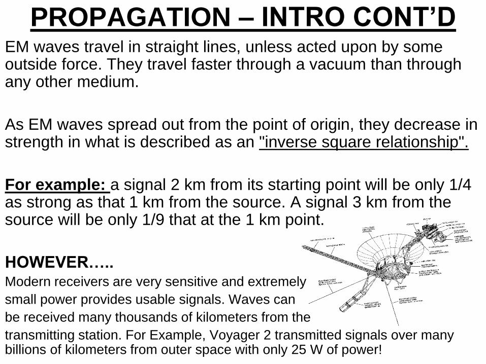
EM waves travel in straight lines, unless acted upon by some outside force. They travel faster through a vacuum than through any other medium.
As EM waves spread out from the point of origin, they decrease in strength in what is described as an "inverse square relationship".
For example: a signal 2 km from its starting point will be only 1/4 as strong as that 1 km from the source. A signal 3 km from the source will be only 1/9 that at the 1 km point.
HOWEVER….. Modern receivers are very sensitive and extremely
small power provides usable signals. Waves can
be received many thousands of kilometers from the
transmitting station. For Example, Voyager 2 transmitted signals over many billions of kilometers from outer space with only 25 W of power!
PROPAGATION – INTRO CONT’D
RADIO WAVES

RADIO WAVES
• Electromagnetic radiation comprises both an Electric and a Magnetic
Field.
• The two fields are at right-angles to each other and the direction of
propagation is at right-angles to both fields.
• The Plane of the Electric Field defines the Polarisation of the wave.
z
x
y
Electric
Field, E
Magnetic
Field, H
Direction of
Propagation
RADIO WAVES CONT’D
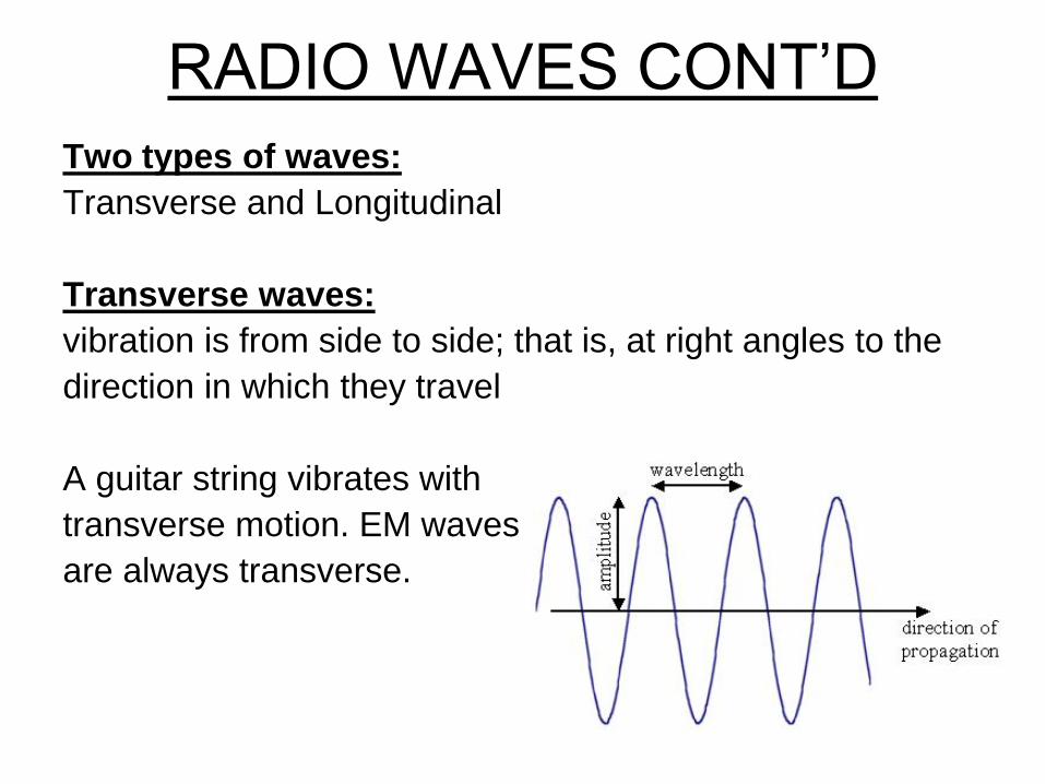
Two types of waves:
Transverse and Longitudinal
Transverse waves:
vibration is from side to side; that is, at right angles to the
direction in which they travel
A guitar string vibrates with
transverse motion. EM waves
are always transverse.
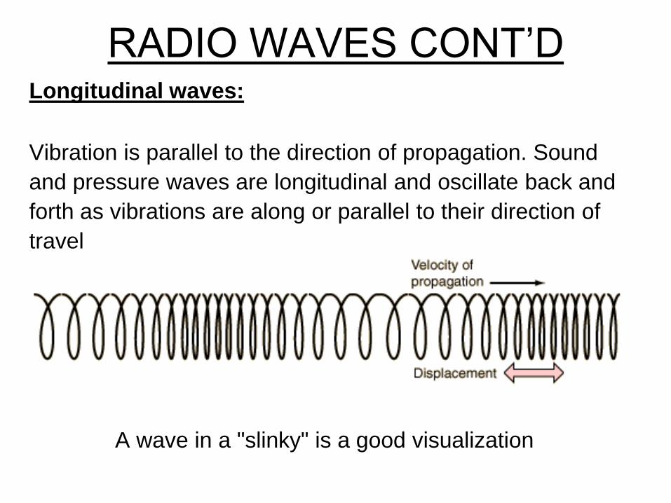
RADIO WAVES CONT’D Longitudinal waves:
Vibration is parallel to the direction of propagation. Sound
and pressure waves are longitudinal and oscillate back and
forth as vibrations are along or parallel to their direction of
travel
A wave in a "slinky" is a good visualization
POLARIZATION
• The polarization of an antenna is the orientation of
the electric field with respect to the Earth's surface
and is determined by the physical structure of the
antenna and by its orientation
• Radio waves from a vertical antenna will usually
be vertically polarized.
• Radio waves from a horizontal antenna are
usually horizontally polarized.
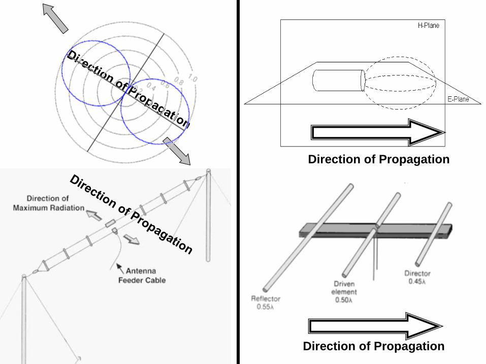
Direction of Propagation
Direction of Propagation
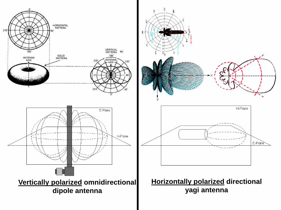
Horizontally polarized directional
yagi antenna Vertically polarized omnidirectional
dipole antenna
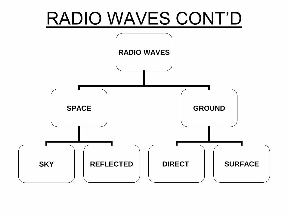
RADIO WAVES CONT’D
RADIO WAVES
SPACE GROUND
SKY REFLECTED DIRECT SURFACE

LINE OF SIGHT, GROUND WAVE,
SKY WAVE • Ground Wave is a Surface Wave that propagates or travels close to the
surface of the Earth.
• Line of Sight (Ground Wave or Direct Wave) is propagation of waves travelling in a straight line. These waves are deviated (reflected) by obstructions and cannot travel over the horizon or behind obstacles. Most common direct wave occurs with VHF modes and higher frequencies. At higher frequencies and in lower levels of the atmosphere, any obstruction between the transmitting antenna and the receiving antenna will block the signal, just like the light that the eye senses.
• Space Waves: travel directly from an antenna to another without reflection on the ground. Occurs when both antennas are within line of sight of each another, distance is longer that line of sight because most space waves bend near the ground and follow practically a curved path. Antennas must display a very low angle of emission in order that all the power is radiated in direction of the horizon instead of escaping in the sky. A high gain and horizontally polarized antenna is thus highly recommended.
• Sky Wave (Skip/ Hop/ Ionospheric Wave) is the propagation of radio waves bent (refracted) back to the Earth's surface by the ionosphere. HF radio communication (3 and 30 MHz) is a result of sky wave propagation.
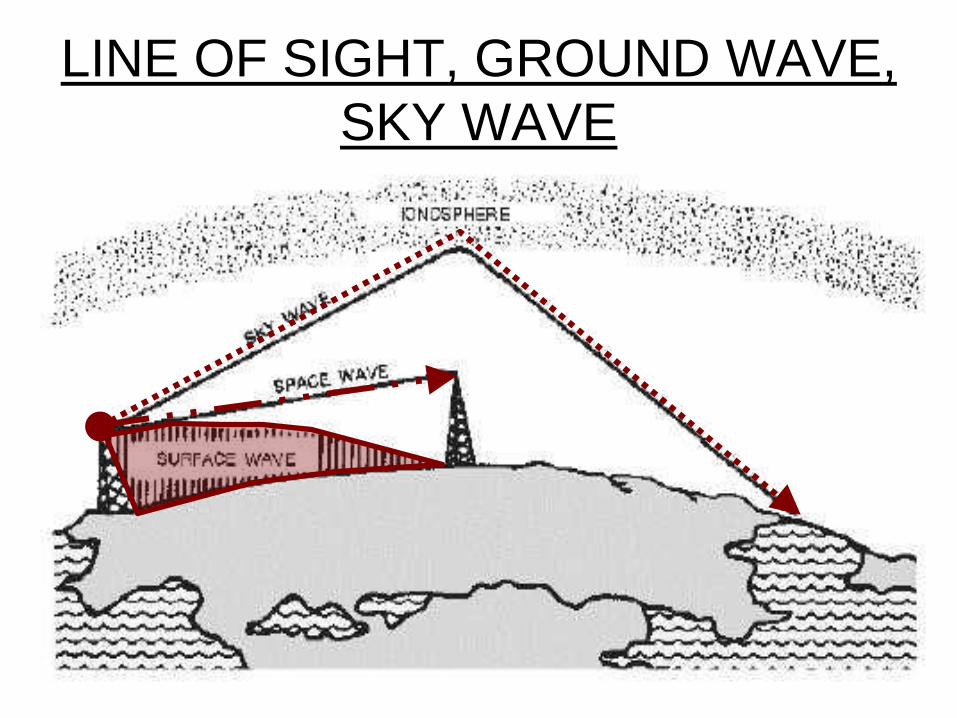
LINE OF SIGHT, GROUND WAVE,
SKY WAVE
KNOWLEDGE CHECK

PROPAGATION, HOPS, SKIPS ZONES

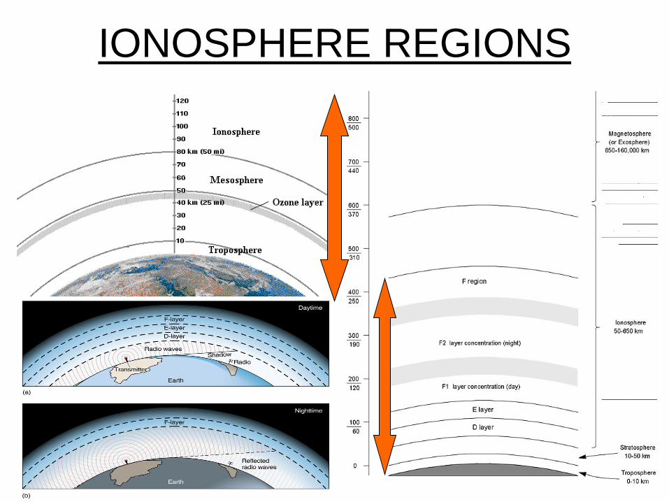
IONOSPHERE REGIONS • The ionosphere is the
uppermost part of the atmosphere and is ionized by solar radiation.
• Ionization is the conversion of atoms or molecules into an ion by light (heating up or charging) from the sun on the upper atmosphere.
• Ionization also creates a horizontal set of stratum (layer) where each has a peak density and a definable width or profile that influences radio propagation.
IONOSPHERE REGIONS
THE IONOSPHERIC LAYERS
The F layer: or region, is 120 km to 400 km above the surface of the Earth. It is the top most layer of the ionosphere. Here extreme ultraviolet (UV) (10-100 nm) solar radiation ionizes atomic oxygen (O). The F region is the most important part of the ionosphere in terms of HF communications. The F layer combines into one layer at night, and in the presence of sunlight (during daytime), it divides into two layers, the F1 and F2. The F layers are responsible for most skywave propagation of radio waves, and are thickest and most reflective of radio on the side of the Earth facing the sun.
The E layer: is the middle layer, 90 km to 120 km above the surface of the Earth. This layer can only reflect radio waves having frequencies less than about 10 MHz. It has a negative effect on frequencies above 10 MHz due to its partial absorption of these waves. At night the E layer begins to disappear because the primary source of ionization is no longer present. The increase in the height of the E layer maximum increases the range to which radio waves can travel by reflection from the layer
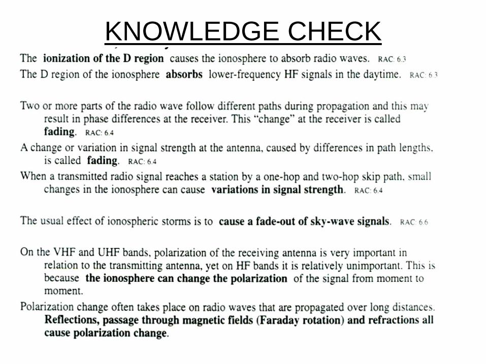
The D layer: is the innermost layer, 50 km to 90 km above the surface of the Earth. when the sun is active with 50 or more sunspots, During the night cosmic rays produce a residual amount of ionization as a result high-frequency (HF) radio waves aren't reflected by the D layer. The D layer is mainly responsible for absorption of HF radio waves, particularly at 10 MHz and below, with progressively smaller absorption as the frequency gets higher. The absorption is small at night and greatest about midday. The layer reduces greatly after sunset. A common example of the D layer in action is the disappearance of distant AM broadcast band stations in the daytime.
THE IONOSPHERIC LAYERS
CONT’D
THE IONOSPHERIC LAYERS
CONT’D Ionospheric Storms: Solar activity such as flares and coronal mass ejections produce large electromagnetic radiation incidents upon the earth and leads to disturbances of the ionosphere; changes the density distribution, electron content, and the ionospheric current system. These storms can also disrupt satellite communications and cause a loss of radio frequencies which would otherwise reflect off the ionosphere. Ionospheric storms can last typically for a day or so.
D layer Absorption: Occurs when the ionosphere is strongly charged (daytime, summer, heavy solar activity) longer waves will be absorbed and never return to earth. You don't hear distant AM broadcast stations during the day. Shorter waves will be reflected and travel further. Absorption occurs in the D layer which is the lowest layer in the ionosphere. The intensity of this layer is increased as the sun climbs above the horizon and is greatest at noon. Radio waves below 3 or 4 MHz are absorbed by the D layer when it is present.
When the ionosphere is weakly charged (night time, winter, low solar activity) longer waves will travel a considerable distance but shorter waves may pass through the ionosphere and escape into space. VHF waves pull this trick all the time, hence their short range and usefulness for communicating with satellites.
Faraday rotation: EM waves passing through the ionosphere may have their polarizations changed to random directions (refraction) and propagate at different speeds. Since most radio waves are either vertically or horizonally polarized, it is difficult to predict what the polarization of the waves will be when they arrive at a receiver after reflection in the ionosphere.
THE IONOSPHERIC LAYERS
CONT’D
SO!!!! • Solar radiation, acting on the different compositions of the atmosphere
generates layers of ionization
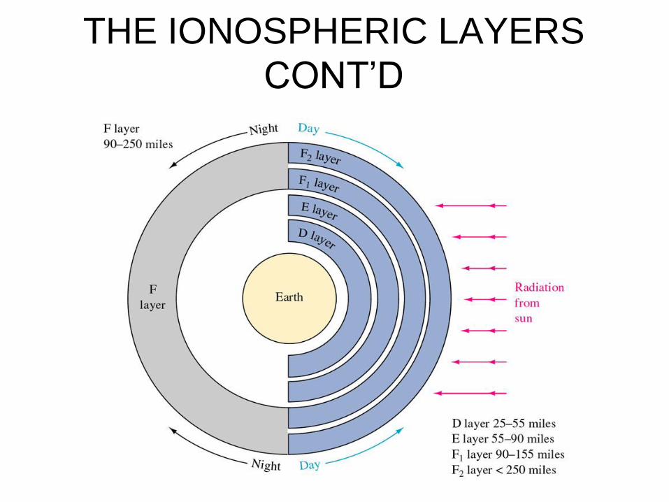
• Studies of the ionosphere have determined that there are at least four distinct layers of D, E, F1, and F2 layers.
• The F layer is a single layer during the night and other periods of low ionization, during the day and periods of higher ionization it splits into two distinct layers, the F1 and F2.
• There are no clearly defined boundaries between layers. These layers vary in density depending on the time of day, time of year, and the amount of solar (sun) activity.
• The top-most layer (F and F1/F2) is always the most densely ionized because it is least protected from the Sun.
KNOWLEDGE CHECK

PROPAGATION, HOPS, SKIPS ZONES
DEFINITIONS
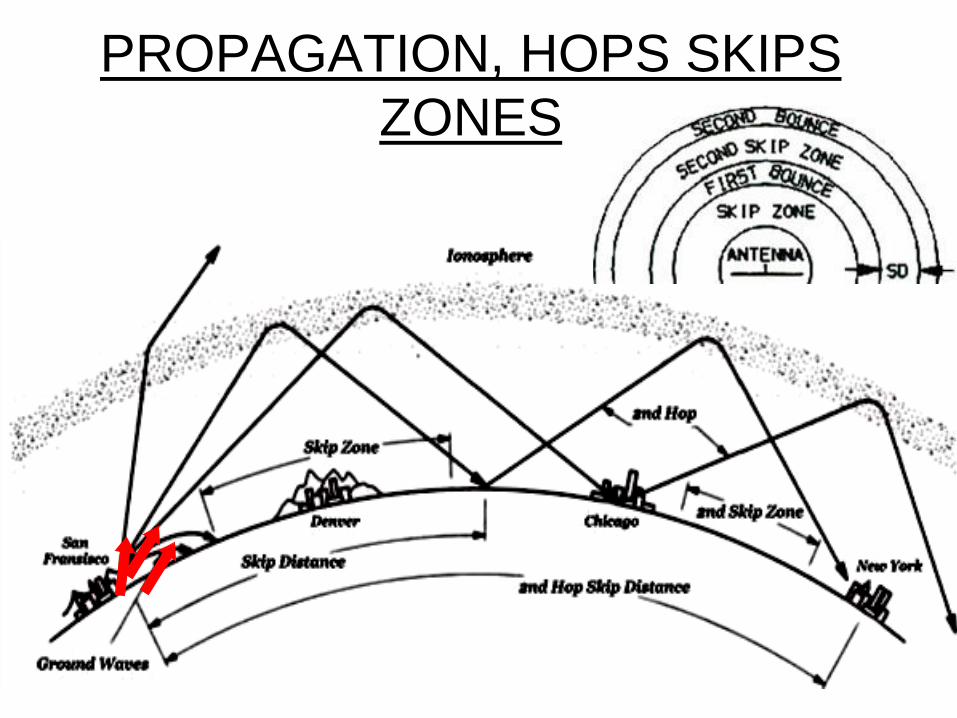
• Multihop: Via the F2-layer signals can reach DX (distant stations) by doing several hops to the other side of the Earth.
• Skip Zone: The region between the furthest transmission points and the nearest point refracted waves can be received. Within this region, no signal can be received as there are no radio waves to receive.
• Skip Distance: The least distance between point of transmission and the point of reception
• Diffraction: High frequency radio waves can bend around the edge of an object such as a spot located out of sight from a transmitter (i.e. behind a hill), the remote radio is able to receive weak emissions because its signals are bending gradually by diffraction. This effect has practically no influence on HF since waves arrive usually to the receiver by many other means such as refraction or reflection in the upper atmosphere including sometimes ground waves if the transmitter is not too far (150-200 km away).
PROPAGATION, HOPS, SKIPS
ZONES
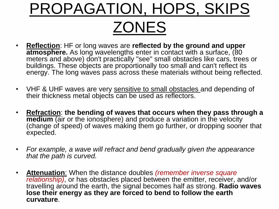
• Reflection: HF or long waves are reflected by the ground and upper atmosphere. As long wavelengths enter in contact with a surface, (80 meters and above) don't practically "see" small obstacles like cars, trees or buildings. These objects are proportionally too small and can't reflect its energy. The long waves pass across these materials without being reflected.
• VHF & UHF waves are very sensitive to small obstacles and depending of their thickness metal objects can be used as reflectors.
• Refraction: the bending of waves that occurs when they pass through a medium (air or the ionosphere) and produce a variation in the velocity (change of speed) of waves making them go further, or dropping sooner that expected.
• For example, a wave will refract and bend gradually given the appearance that the path is curved.
• Attenuation: When the distance doubles (remember inverse square relationship), or has obstacles placed between the emitter, receiver, and/or travelling around the earth, the signal becomes half as strong. Radio waves lose their energy as they are forced to bend to follow the earth curvature.
PROPAGATION, HOPS, SKIPS
ZONES
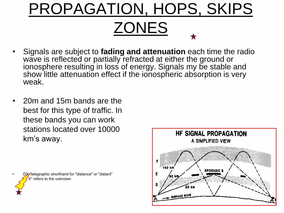
• Signals are subject to fading and attenuation each time the radio wave is reflected or partially refracted at either the ground or ionosphere resulting in loss of energy. Signals my be stable and show little attenuation effect if the ionospheric absorption is very weak.
• 20m and 15m bands are the
best for this type of traffic. In
these bands you can work
stations located over 10000
km’s away.
• DX, telegraphic shorthand for "distance" or "distant”
& "X" refers to the unknown

Refraction is the change in
direction of a wave due to
a change in its speed
Reflection is the
change in direction
of a wave front at an
interface between
two different media
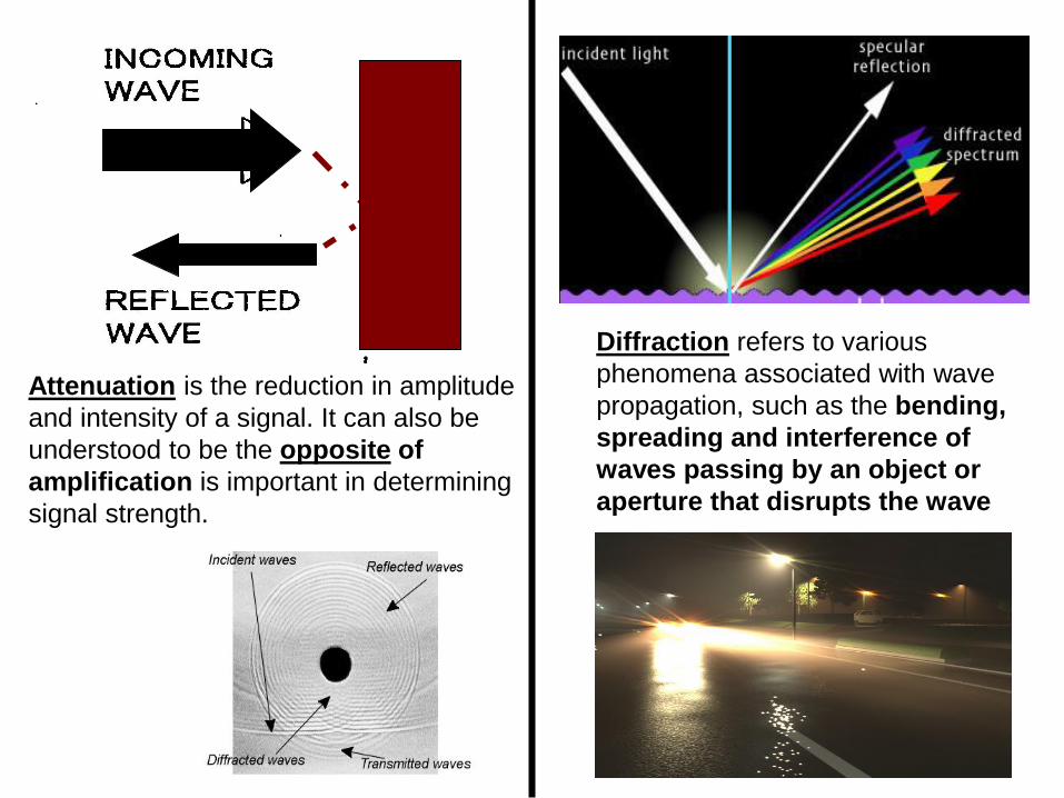
Diffraction refers to various
phenomena associated with wave
propagation, such as the bending,
spreading and interference of
waves passing by an object or
aperture that disrupts the wave
Attenuation is the reduction in amplitude
and intensity of a signal. It can also be
understood to be the opposite of
amplification is important in determining
signal strength.
PROPAGATION, HOPS SKIPS
ZONES
PROPAGATION, HOPS SKIPS
ZONES CONT’D
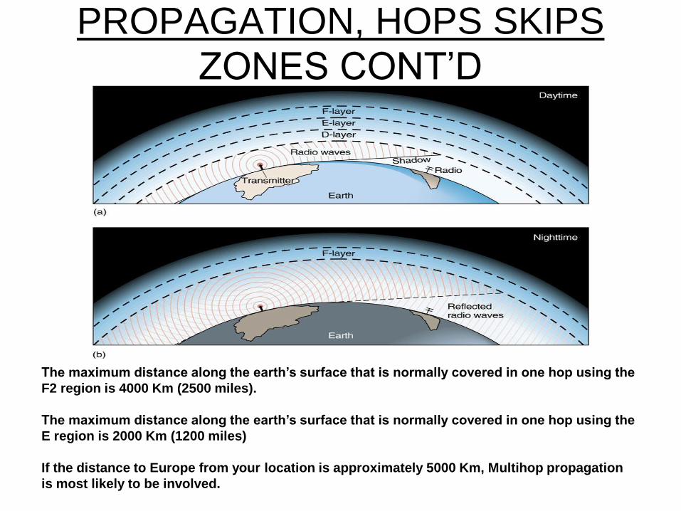
The maximum distance along the earth’s surface that is normally covered in one hop using the
F2 region is 4000 Km (2500 miles).
The maximum distance along the earth’s surface that is normally covered in one hop using the
E region is 2000 Km (1200 miles)
If the distance to Europe from your location is approximately 5000 Km, Multihop propagation
is most likely to be involved.
ABSORPTION AND FADING

ABSORPTION AND FADING Fading of signals is the effect at a receiver do to a disturbed propagation path. A local
station will come in clearly, a distant station may rise and fall in strength or appear garbled.
Fading may be caused by a variety of factors:
a. A reduction of the ionospheric ionization level near sunset.
b. Multi-path propagation: some of the signal is being reflected by one layer of the ionosphere and some by another layer. The signal gets to the receiver by two different routes The received signal may be enhanced or reduced by the wave interactions. In essence, radio signals' reaching the receiving antenna by two or more paths. Causes include atmospheric ducting (more on this latter), ionospheric reflection and refraction, and reflection from terrestrial objects, such as mountains and buildings.
c. Increased absorption as the D layer builds up during the morning hours.
d. Difference in path lengths caused by changing levels of ionization in the reflecting layer.
e. E layer starts to disappear radio waves will pass through and be reflected by the F layer, thus causing the skip zone to fall beyond the receiving station.
f. Selective fading: similar to Multi-path propagation, creates a hollow tone common on international shortwave AM reception. The signal arrives at the receiver by two different paths, and at least one of the paths is changing (lengthening or shortening). This typically happens in the early evening or early morning as the various layers in the ionosphere move, separate, and combine. The two paths can both be skywave or one can be ground wave.

ABSORPTION AND FADING
Received signal Transmission signal
Different paths
KNOWLEDGE CHECK
SOLAR ACTIVITY AND SUN SPOTS
SOLAR ACTIVITY AND SUN
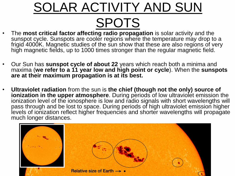
SPOTS • The most critical factor affecting radio propagation is solar activity and the
sunspot cycle. Sunspots are cooler regions where the temperature may drop to a frigid 4000K. Magnetic studies of the sun show that these are also regions of very high magnetic fields, up to 1000 times stronger than the regular magnetic field.
• Our Sun has sunspot cycle of about 22 years which reach both a minima and maxima (we refer to a 11 year low and high point or cycle). When the sunspots are at their maximum propagation is at its best.
• Ultraviolet radiation from the sun is the chief (though not the only) source of ionization in the upper atmosphere. During periods of low ultraviolet emission the ionization level of the ionosphere is low and radio signals with short wavelengths will pass through and be lost to space. During periods of high ultraviolet emission higher levels of ionization reflect higher frequencies and shorter wavelengths will propagate much longer distances.

SOLAR ACTIVITY AND SUN
SPOTS CONT’D Emission of larger amounts of ultraviolet radiation corresponds to increased surface activity on the sun.
Length of a solar cycle can vary by one or two years in either direction from the 22 and 11 year average but it has remained near this value throughout geologic time.
Solar maxima can also lead to highly variable propagation conditions due to periods of disturbance during solar magnetic disturbances (solar storms) which occur at this period.
Solar Flux (Index): is a measure of the radio energy emitted from the sun. The solar flux value is considered to be one of the best ways of relating solar activity to propagation. When sun spot cycles hit their peaks the solar flux may have a value over 200. When the sun spot cycle is at its lowest point the solar flux values can be as low as 50 or 60. The higher the solar flux value the better propagation will be.
Coronal Mass Ejections (CME)

SOLAR ACTIVITY AND SUN
SPOTS CONT’D • Electromagnetic emissions and particle emissions hit the Earths ionosphere
at various speeds with different energy levels. Effects of their impact varies accordingly but mainly affects sky waves. The particles emitted are accompanied by a tiny pulse of electromagnetic radiation. Electromagnetic and particle radiations can potentially modify the ionosphere and affect its properties.
• Electromagnetic emissions hit first the F-layer of the ionosphere increasing its ionization; atoms and molecules warm up and free one or more electrons. The higher the solar activity, the stronger the ionization of the F-layer. A strong ionization of the F-layer increases its reflecting power. Stronger ionization increase or raise the Maximum Usable Frequency or (MUF) (next section), regularly by 40 or 50 MHz in such occasions.
• Particle emissions are constituted of high-energy protons electrons forming solar cosmic rays when the sun releases huge amount of energy in Coronal Mass Ejections (CME). These particles of protons and heavy nuclei propagate into space, creating a shockwave. The pressure created by the particles clouds is huge and has a large effect on the ionosphere communications are interrupted
KNOWLEDGE CHECK
• MF, HF CRITICAL FREQUENCIES
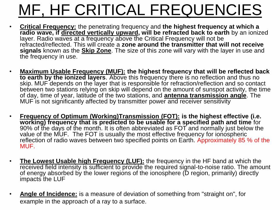
MF, HF CRITICAL FREQUENCIES • Critical Frequency: the penetrating frequency and the highest frequency at which a
radio wave, if directed vertically upward, will be refracted back to earth by an ionized layer. Radio waves at a frequency above the Critical Frequency will not be refracted/reflected. This will create a zone around the transmitter that will not receive signals known as the Skip Zone. The size of this zone will vary with the layer in use and the frequency in use.
• Maximum Usable Frequency (MUF): the highest frequency that will be reflected back to earth by the ionized layers. Above this frequency there is no reflection and thus no skip. MUF depends on the layer that is responsible for refraction/reflection and so contact between two stations relying on skip will depend on the amount of sunspot activity, the time of day, time of year, latitude of the two stations, and antenna transmission angle. The MUF is not significantly affected by transmitter power and receiver sensitivity
• Frequency of Optimum (Working)Transmission (FOT): is the highest effective (i.e. working) frequency that is predicted to be usable for a specified path and time for 90% of the days of the month. It is often abbreviated as FOT and normally just below the value of the MUF. The FOT is usually the most effective frequency for ionospheric reflection of radio waves between two specified points on Earth. Approximately 85 % of the MUF.
• The Lowest Usable high Frequency (LUF): the frequency in the HF band at which the received field intensity is sufficient to provide the required signal-to-noise ratio. The amount of energy absorbed by the lower regions of the ionosphere (D region, primarily) directly impacts the LUF
• Angle of Incidence: is a measure of deviation of something from "straight on", for
example in the approach of a ray to a surface.

MF, HF CRITICAL FREQUENCIES
Maximum Useful Frequency
(MUF)
Frequency of optimum
transmission (FOT) /Optimal
Working Frequency (OWF)
Lower Absorption Frequency
(ALF) / The lowest Usable
frequency (LUF):
Above Critical Frequency
MF, HF CRITICAL FREQUENCIES
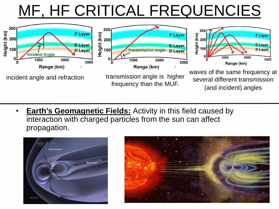
• Earth's Geomagnetic Fields: Activity in this field caused by interaction with charged particles from the sun can affect propagation.
incident angle and refraction transmission angle is higher
frequency than the MUF.
waves of the same frequency at
several different transmission
(and incident) angles
KNOWLEDGE CHECK
(More on beacons latter on!)

KNOWLEDGE CHECK CONT’D

• UHF, VHF, SPORADIC E, AURORAS,
DUCTING

UHF, VHF, SPORADIC E, AURORAS,
DUCTING
Propagation above 30 MHz is normally not affected by conditions of the ionosphere. These radio waves pass through the ionosphere without refraction and escape to space. These frequencies are useful for Direct Wave Communication and for working Amateur satellites (ARISS / OSCAR) and moon-bounce (EME). The 6 metre band is an exception as under conditions of high sunspot activity it acquires some of the characteristics of the 10 metre band.
The VHF band and above use direct waves and line of sight communications. The range of propagation can be slightly greater at times by a factor of 4/3 due to refraction effects in the Troposphere. This means under the right conditions, you can make contact with stations beyond the horizon. The effects diminish as the frequency increases. In certain favorable locations, enhanced tropospheric propagation may enable reception signals up to 800 miles or more.
Other conditions which affect the propagation of VHF signals (and above) are:
Sporadic-E: strongly ionized clouds can occur in the "E“ layer of the ionosphere and VHF signals will be refracted back to earth extending the range to a few thousand kilometers. Conditions occur primarily in the spring and late fall. Until recently 50 MHz (6 metre band) was considered to be the highest frequency useable for Sporadic-E operation. Increased 2 metre activity in the last decades show several DX records have been set using suspected Sporadic-E propagation and the highest frequency at which this propagation mode can be used must be considered to be as yet unknown.

UHF, VHF, SPORADIC E, AURORAS,
DUCTING Temperature Inversion / Troposphere Ducting: Certain weather conditions
produce a layer of air in the Troposphere that will be at a higher temperature
than the layers of air above and below it. Such a layer will provide a "duct"
creating a path through the warmer layer of air which has less signal loss than
cooler layers above and below. These ducts occur over relatively long
distances and at varying heights from almost ground level to several hundred
meters above the earth's surface. This propagation takes place when hot days
are followed by rapid cooling at night and affects propagation in the 50 MHz -
450 MHz range (6 meter, 2 meter, 1 1/4 meter and 70 centimeter bands).
Signals can propagate hundreds of kilometers up to about 2,000 kilometers
(1,300 mi).
UHF, VHF, SPORADIC E, AURORAS,
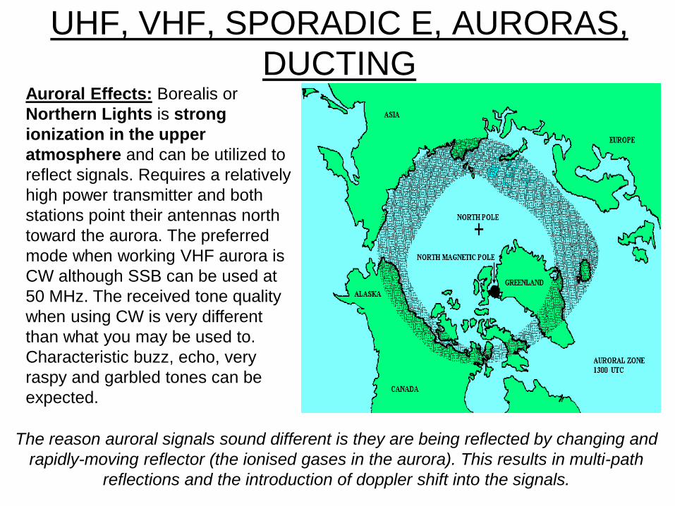
DUCTING Auroral Effects: Borealis or
Northern Lights is strong
ionization in the upper
atmosphere and can be utilized to
reflect signals. Requires a relatively
high power transmitter and both
stations point their antennas north
toward the aurora. The preferred
mode when working VHF aurora is
CW although SSB can be used at
50 MHz. The received tone quality
when using CW is very different
than what you may be used to.
Characteristic buzz, echo, very
raspy and garbled tones can be
expected.
The reason auroral signals sound different is they are being reflected by changing and
rapidly-moving reflector (the ionised gases in the aurora). This results in multi-path
reflections and the introduction of doppler shift into the signals.
UHF, VHF, SPORADIC E, AURORAS,
DUCTING
Hilly Terrain: mountainous area signals tend to be much shorter than those in open country. Signals are reflected off mountains and are also absorbed by them. If a signal passes over the top of a hill it may bend or refract back down the other side.
The Concrete Jungle: Propagation in the city is similar to the effects found in mountainous terrain. A city will often be plagued by "mobile flutter", caused by multiple reflections of the signal off buildings. A move of 20 cm or so can make all the difference in the world. Working through a repeater can be complicated by the fact that you are using two different frequencies (some times called fence picketing).
Equatorial E-skip: a regular daytime occurrence over the equatorial regions and is common in the temperate latitudes in late spring, early summer and, to a lesser degree, in early winter. For receiving stations located within +/− 10 degrees of the geomagnetic equator, equatorial E-skip can be expected on most days throughout the year, peaking around midday local time.
Earth – Moon – Earth (EME) propagation (Moon Bounce): Radio amateurs have been experimenting with lunar communications by reflecting VHF and UHF signals off the moon between any two points that can observe the moon at a common time. Distance from earth means path losses are very high. The resulting signal level is often just above the noise.
KNOWLEDGE CHECK
• SCATTER, HF, VHF,UHF
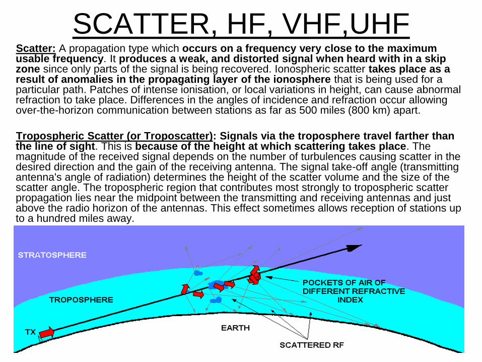
SCATTER, HF, VHF,UHF Scatter: A propagation type which occurs on a frequency very close to the maximum usable frequency. It produces a weak, and distorted signal when heard with in a skip zone since only parts of the signal is being recovered. Ionospheric scatter takes place as a result of anomalies in the propagating layer of the ionosphere that is being used for a particular path. Patches of intense ionisation, or local variations in height, can cause abnormal refraction to take place. Differences in the angles of incidence and refraction occur allowing over-the-horizon communication between stations as far as 500 miles (800 km) apart.
Tropospheric Scatter (or Troposcatter): Signals via the troposphere travel farther than the line of sight. This is because of the height at which scattering takes place. The magnitude of the received signal depends on the number of turbulences causing scatter in the desired direction and the gain of the receiving antenna. The signal take-off angle (transmitting antenna's angle of radiation) determines the height of the scatter volume and the size of the scatter angle. The tropospheric region that contributes most strongly to tropospheric scatter propagation lies near the midpoint between the transmitting and receiving antennas and just above the radio horizon of the antennas. This effect sometimes allows reception of stations up to a hundred miles away.
SCATTER, HF, VHF,UHF
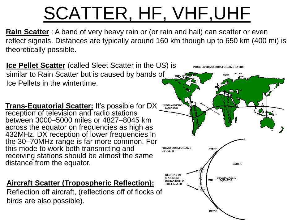
Trans-Equatorial Scatter: It’s possible for DX reception of television and radio stations between 3000–5000 miles or 4827–8045 km across the equator on frequencies as high as 432MHz. DX reception of lower frequencies in the 30–70MHz range is far more common. For this mode to work both transmitting and receiving stations should be almost the same distance from the equator.
Aircraft Scatter (Tropospheric Reflection):
Reflection off aircraft, (reflections off of flocks of
birds are also possible).
Rain Scatter : A band of very heavy rain or (or rain and hail) can scatter or even
reflect signals. Distances are typically around 160 km though up to 650 km (400 mi) is
theoretically possible.
Ice Pellet Scatter (called Sleet Scatter in the US) is
similar to Rain Scatter but is caused by bands of
Ice Pellets in the wintertime.
SCATTER, HF, VHF,UHF
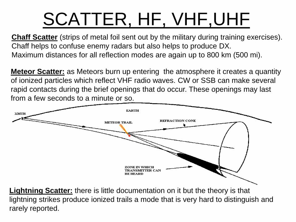
Meteor Scatter: as Meteors burn up entering the atmosphere it creates a quantity
of ionized particles which reflect VHF radio waves. CW or SSB can make several
rapid contacts during the brief openings that do occur. These openings may last
from a few seconds to a minute or so.
Lightning Scatter: there is little documentation on it but the theory is that
lightning strikes produce ionized trails a mode that is very hard to distinguish and
rarely reported.
Chaff Scatter (strips of metal foil sent out by the military during training exercises).
Chaff helps to confuse enemy radars but also helps to produce DX.
Maximum distances for all reflection modes are again up to 800 km (500 mi).

KNOWLEDGE CHECK Scatter propagation would best be used by two stations within each other’s skip zone on a certain or close to
the MUF.
If you receive a weak, distorted signal from a distance, and close to maximum usable frequency, scatter
propagation is probably occurring.
A wavering sound is characteristic of HF scatter signals
Energy scattered into the skip zone through several radio-wave paths makes HF scatter Signals often
sound distorted.
HF scatter signals are usually weak because only a small part of the signal energy is scattered into the
skip zone.
Scatter propagation allows a signal to be detected at a distance to far for ground-wave propagation but to near
for normal sky-wave propagation.
Scatter propagation on the HF bands most often occurs when communicating on frequencies above and
close to the maximum usable frequency (MUF)
Side, Back, and Forward, Meteor, Ionospheric, and Tropospheric ARE all scatter modes.
Inverted and Absorption are NOT scatter modes.
In the 30 – 100 MHz frequency range, meteor scatter is NOT the most effective for extended-range
communications.
Meteor scatter is the most effective on the 6 metre band.
BEACONS
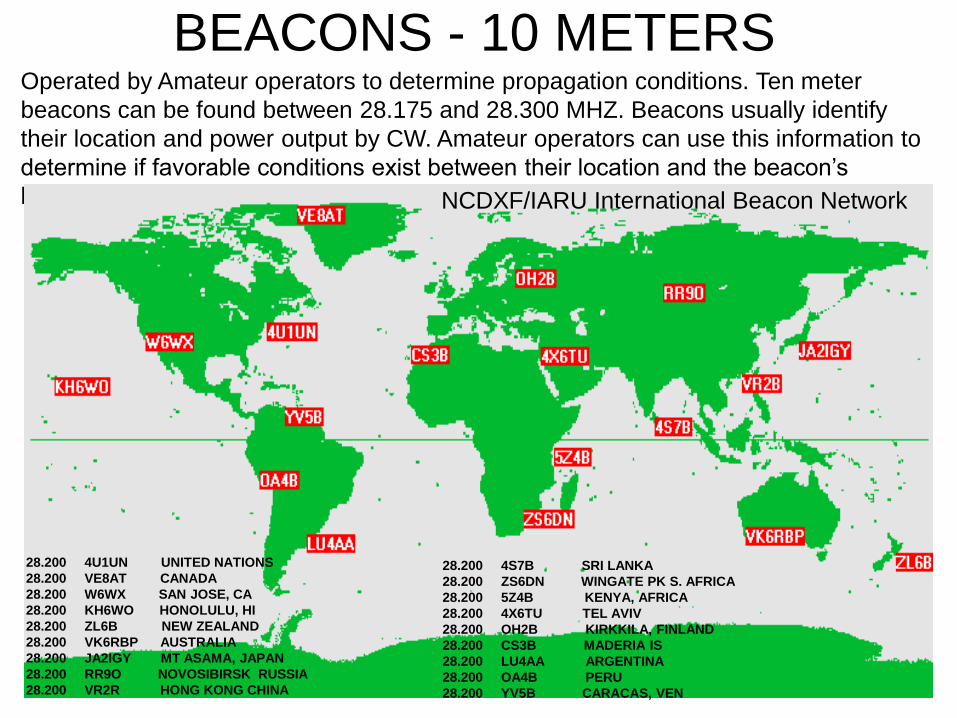
BEACONS - 10 METERS Operated by Amateur operators to determine propagation conditions. Ten meter
beacons can be found between 28.175 and 28.300 MHZ. Beacons usually identify
their location and power output by CW. Amateur operators can use this information to
determine if favorable conditions exist between their location and the beacon’s
location. NCDXF/IARU International Beacon Network
28.200 4S7B SRI LANKA
28.200 ZS6DN WINGATE PK S. AFRICA
28.200 5Z4B KENYA, AFRICA
28.200 4X6TU TEL AVIV
28.200 OH2B KIRKKILA, FINLAND
28.200 CS3B MADERIA IS
28.200 LU4AA ARGENTINA
28.200 OA4B PERU
28.200 YV5B CARACAS, VEN
28.200 4U1UN UNITED NATIONS
28.200 VE8AT CANADA
28.200 W6WX SAN JOSE, CA
28.200 KH6WO HONOLULU, HI
28.200 ZL6B NEW ZEALAND
28.200 VK6RBP AUSTRALIA
28.200 JA2IGY MT ASAMA, JAPAN
28.200 RR9O NOVOSIBIRSK RUSSIA
28.200 VR2R HONG KONG CHINA
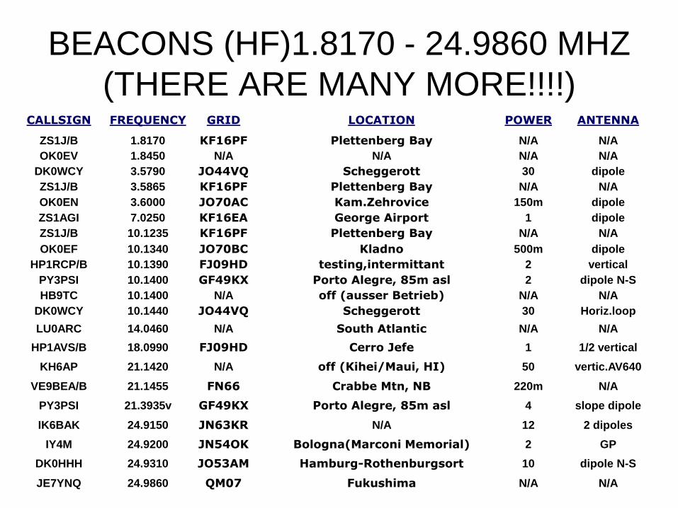
BEACONS (HF)1.8170 - 24.9860 MHZ
(THERE ARE MANY MORE!!!!) CALLSIGN FREQUENCY GRID LOCATION POWER ANTENNA
ZS1J/B 1.8170 KF16PF Plettenberg Bay N/A N/A
OK0EV 1.8450 N/A N/A N/A N/A
DK0WCY 3.5790 JO44VQ Scheggerott 30 dipole
ZS1J/B 3.5865 KF16PF Plettenberg Bay N/A N/A
OK0EN 3.6000 JO70AC Kam.Zehrovice 150m dipole
ZS1AGI 7.0250 KF16EA George Airport 1 dipole
ZS1J/B 10.1235 KF16PF Plettenberg Bay N/A N/A
OK0EF 10.1340 JO70BC Kladno 500m dipole
HP1RCP/B 10.1390 FJ09HD testing,intermittant 2 vertical
PY3PSI 10.1400 GF49KX Porto Alegre, 85m asl 2 dipole N-S
HB9TC 10.1400 N/A off (ausser Betrieb) N/A N/A
DK0WCY 10.1440 JO44VQ Scheggerott 30 Horiz.loop
LU0ARC 14.0460 N/A South Atlantic N/A N/A
HP1AVS/B 18.0990 FJ09HD Cerro Jefe 1 1/2 vertical
KH6AP 21.1420 N/A off (Kihei/Maui, HI) 50 vertic.AV640
VE9BEA/B 21.1455 FN66 Crabbe Mtn, NB 220m N/A
PY3PSI 21.3935v GF49KX Porto Alegre, 85m asl 4 slope dipole
IK6BAK 24.9150 JN63KR N/A 12 2 dipoles
IY4M 24.9200 JN54OK Bologna(Marconi Memorial) 2 GP
DK0HHH 24.9310 JO53AM Hamburg-Rothenburgsort 10 dipole N-S
JE7YNQ 24.9860 QM07 Fukushima N/A N/A

Sample Questions From The IC Question Bank A. The medium which reflects HF radio waves back to the earth's surface is called:
1) biosphere
2) stratosphere
3) ionosphere
4) troposphere
B. All communications frequency throughout the spectrum are affected in varying degrees by:
1) atmospheric conditions
2) ionosphere
3) aurora borealis
4) sun
C. Solar cycles have an average length of:
1) 1 year
2) 3 years
3) 6 years
4) 11 years
D. Wave energy produced on frequencies below 4 MHz during daylight hours is almost always absorbed by the - layer:
1) C
2) D
3) E
4) F
E. If the distance to Europe from your location is approximately 5000 km what sort of propagation is the most likely to be involved?
1) sporadic-E
2) tropospheric scatter
3) back scatter
4) Multihop
KNOWLEDGE CHECK

-END-