radiation exposures unit 2 chapters 10, 15, 16, and 18
TRANSCRIPT
Radiation Exposures Unit 2
CHAPTERS 10, 15, 16, AND 18
Objectives • Define filtration, inherent filtration, added
filtration , compound filtration, compensating filtration and total filtration.
• Explain concept of half-value layer equivalency measurements of filtration.
• Appraise various types of filters for specific clinical situations.
• Describe effect of filtration on entire x-ray beam.
• Identify the factors that affect scatter.
• Discuss types of scatter control used by radiographers
• Explain the purpose, construction, advantages and disadvantages of beam-restricting devices.
• Describe the effect of beam restriction on image quality and patient dose.
• Explain the process of attenuation
• Describe the basic composition of the human body and how they attenuate the x-ray beam
• Explain the relationship of the patient to density/image receptor exposure, contrast, recorded detail and distortion of the recorded image.
• Describe the purpose of a grid and its construction
• Explain: material, ratio, frequency and lead content
• Differentiate various grid patterns.
• Describe: parallel vs focused grids and stationary vs moving grids.
• Explain grid and technique selection based on : patient , procedure, dose and IR exposure.
• Discuss proper use and errors with grids and how both effect the image.
Chapter 10FILTRATION
Filtration • The process of eliminating undesirable low-energy photons by
inserting absorbing material into the primary beam
• Shape the photon emissions into a more useful beam
• “hardens” the beam
• Removes low energy (soft ) photons
• Main Purpose
• Decreases radiation dose to the patient by removing photons that would not enhance the image.
Filter• Any material designed to selectively absorb photons
• Placed between the tube( source) and the patient
• Aluminum
• Most common / standard filter material used
• All other materials are measured against it ability to filter- Aluminum equivalency
(Al/Eq)
Alternated Materials
glass, oil , copper and tin
Measurement of Filtration • Express in half-value layer ( HVL ) – amount of absorbing material to
reduce the intensity of the primary beam by ½ the original value
• Also expressed in Al/Eq example : HVL = 2.0 mm Al/Eq
• Federal govt. specifies min HVL for diagnostic tubes:
• 2.5 mm Al/Eq
Types of Filtration• 2 types:
• Inherent – in the design of the tube
• Added- between tube and image receptor
Inherent filtration• Result of composition of tube and housing
• Glass envelope
• Oil surrounding tube
• Glass window – where most of the filtration comes from
• Total inherent is 0.5-1.0
• Increases as tube ages because of vaporization of tungsten
• HVL testing for QC tests for reduced tube efficiency because of the added filtration
Added Filtration • Any filtration that occurs outside the tube but before the IR
• Absorb as many low-energy photons as possible while allowing max amount of high-energy photons through.
• Aluminum used as a low energy absorber
• Collimators are considered added_ 1.0 mm Al/Eq
• Most comes from the silver on the mirror that reflects the positioning light.
Types of Added Filtration Compound filtration ( AKA: K-Edge)
• Uses two or more material that work together well to absorb
• High atomic number material sandwiched with a lower atomic number material • Cooper ( 29) with Al ( 13)
• Built to absorb characteristic photons ( K shell photons) created by the previous layer• The higher atomic number will absorb higher energies but Al is needed to absorb
the lower energy photons created.
• Examples: Thoreaus filter- used in radiation therapy
Some QC testing uses copper + Al filters
Types of Added Filtration • Compensation Filters
• Designed to solve a problem of unequal subject densities
• Produces a more uniform IR exposure
• Components:
• AL, Lead, leaded plastic or plastic – saline solution bag
• Common types
• Wedge- thicker portion is placed over thinner part- foot, t-spine
• Trough ( double wedge) – chest to even out mediastinum
Total Filtration • Equal to the sum of inherent + added filtration but DOES not
include compensating filters
• Thickness depends on use of equipment
• Above 70 kVp 2.5 mm Al
Effect on Output• As filtration increases- technical factors must increase to maintain IR
exposure
• Even though there is an increase in technique necessary for compensation- the ESE is decreased as compared to no filtration in place at lower techniques
• See table 10-4 page 176

Beam Restriction CHAPTER 15
Scatter• Product of Compton interactions ( scatter that contributes to fog and
tech dose)
• Not part of the useful beam
• Impair image quality by adding exposure to the IR unrelated to patient anatomy
• Best way to control scatter reaching the IR is to use a grid.
• Best way to control scatter to the patient is use beam restriction.
• Principle factors affecting scatter
1. kilovoltage
2. irradiated material
1. Kilovoltage• As kVp increases
• More photons pass through the patient to interact with the image receptor
• Image quality is increased with less scatter
• Photons that do not pass through the matter interact as Compton and photoelectric interactions
• Higher kVp will increase Compton( scatter) and decrease photoelectric ( pt dose)
• Since photoelectric contribute to patient dose, dose will be decreased
• kVp should be based on part/anatomy thickness /size and the amount of contrast desired
• Increased kVp with NO change in mAs : increased scatter
• Increased kVp and reduction in mAs: decreased scatter
2. Irradiated Material • Scatter is affected by the volume and atomic number of the material being x-
rayed.
• Volume is controlled by field size and patient thickness
• Increased volume increases scatter ( more interactions)
• Volume increases as part increases and as field size increase • 14 x17 has more volume than 10 x 12 – increased scatter , so smallest field size should be
used
• Large patients should have better collimation to decrease interaction ( decrease scatter)
• When collimation is used- more technique is needed ( 14x17 to 10x12- aprox increase is 25% , 14x17 to 8 x 10 aprox increase of 40%)
• Higher atomic numbers will have less scatter- they absorb more through photoelectric absorption- more contrast ( black and white)
• Bone absorbs more than soft tissue- less scatter
• Iodine, Ba and Pb absorbs more- less scatter
Types of Beam Restrictors 1. Collimators
2. Aperture diaphragms and cones / cylinders
3 . Ancillary devices
1. Collimator• Most common beam restrictor – results in filtration of the beam –
aprox 1 mm of Al
• Multiple size configurations- but should always be minimized to the part being radiographed
• Lead shutters at right angles and move in opposing pairs
• 3 purposes:
1. Regulate field size
2. Reduce penumbra
3. Act as a light field
Field Size• Various square or rectangle shapes
• PBL device - positive beam limitation device- automatic collimation of the beam size- works with a sensor in the Bucky tray to determine film size being used.
• Collimator accuracy must be checked yearly – Within 2 % of the distance
Penumbra • Geometric unsharpness around the edge of the image
• Result of off focus radiation – photons emerge at different angles from the tube and interact with the tissue at various angles and create a “shadow “ image outside the exposed field of radiation
• Reducing penumbra will increase recorded detail
Light Field • Provides an exposure field with crosshair
• Some units will have an AEC chamber outline
• Lightbulb is placed at a 450 to a mirror – improper placement of the mirror can cause a mis-projection of the light and misrepresent the field size
2. Aperture diaphragms and cones / cylinders
• Aperture diaphragm- flat sheet of metal( Pb) with opening cut in the middle
• Attached to the bottom of the collimator box
• Simplest of all beam limiting devices
• Different sizes for different receptor sizes at different distances
• Mostly seen in mammography because they don’t use collimators
• Cones and cylinders
• Circular aperture diaphragm with metal extensions
• Can flare or diverges- small at top than bottom
• Most effective use of scatter control
3. Ancillary Devices • Designed for a specific need and are tailored for specific use during
a given procedure
• Lead blockers or lead masks
• Blockers
• Lead impregnated rubber
• Used to absorb scatter created from soft tissue- used a lot on larger patients
• May be placed behind a patient’s back on an lateral L-spine
• Masks
• cut to a specific shape and attached to collimator

Chapter 16 THE PATIENT AS A BEAM EMITTER
Attenuation• The reduction in the total number of x-ray photons remaining in the
beam after passing through an object
• Result of :
• x-rays interacting with matter and being absorbed or scattered• The thicker the body part, the more attenuation
• Photoelectric absorption( provides information) and Compton scattering ( no useful info- only dose to tech )
• Determined by the amount or type of irradiated material
• High atomic number = higher attenuation – bone , barium, lead
• Low atomic number= low attenuation- hydrogen, carbon, oxygen
• Lowes to highest attenuators in body by density: Air, fat, water, muscle, bone

The Patient • The greatest variable
• Atomic makeup : hydrogen (atomic # 1) , carbon(6), nitrogen(7) and oxygen(8) calcium (20)
• 4 Major substances account for most variations in absorption:
• Air
• Fat
• Muscle
• Bone
1. Air• Higher atomic number than fat or muscle but lower tissue density
• Absorbs fewer photons as it passes through allowing more photons to reach IR
• Present in : ?????
• Lungs
• Sinuses
• GI tract
2. Fat• Similar to muscle- both soft tissue structures- fat has less tissue
density
• Effective atomic number similar to water- water is used to simulate fat in experiments
• Varies from patient to patient
• Fat sometimes allow for better visualization of certain organs during x-raying
• kidneys
3. Muscle • Higher atomic number and density than fat- cells are packed closer
together
• Greater attenuator
• Can often see psoas muscles on abdomen radiograph
4. Bone• Calcium level in bones makes them higher attenuators
• Highest effective atomic number and tissue density of the four basic substances of the body
• Results in few photons reaching the IR
Patients Relationship to Image Quality• Patient has affect on all properties of image quality
1. Density/image receptor exposure ( subject density)
2. Contrast ( subject contrast)
3. Recorded detail ( subject detail )
4. Distortion ( subject distortion)
1. Subject Density • The impact the subject has on the resultant radiographic density or
IR exposure
• Varies depending on the amount or type of tissue being irradiated
• Thicker the part/ more dense the tissue = less IR exposure
2. Subject Contrast• The difference in densities of a recorded image
• The degree of differential absorption resulting from the differing absorption characteristics of the tissue in the body
• Dependent on patient’s tissues
• Less difference in adjacent densities- fat and muscle- less contrast
• More difference in adjacent densities- bone and air- more contrast
3. Subject Detail • Primary factor affecting sharpness in distance from structure to IR
• Dependent on where structure is in the body• Even size of body- larger patients the part is further away from IR
• How the patient is positioned• PA vs AP, RT vs LT lateral
4. Subject Distortion• The misrepresentation of size or shape of the structure of interest
• Varies with patient position

Chapter 18THE GRID
Invention of the Grid• 1913- Gustav Bucky, an American radiologist, designed the first grid
• Designed in a cross-hatched pattern using lead strips
• Grid showed on image but decrease scatter and improved contrast
• 1920- Hollis Potter, a Chicago radiologist, improved Bucky’s design
• Redesigned lead to run in one direction
• Made lead thinner and less obvious on image
Potter also designed the Potter-Bucky diaphragm- allowed for the grid move during exposure
• Lead strips became blurred and were no longer visible
Purpose• Improves contrast of the image
• Absorbs scatter before reaching the IR
• Used with thicker body parts and higher kVp since scatter increases as both of these increase
• Greater than 10cm
• kVp above 60
Construction• Series of radiopaque strips alternated with interspace strips
• Radiopaque strips absorb scatter and are made of high atomic number material
• Interspace is radiolucent – allows radiation to pass through without interaction
• Construction Involves:
1. materials
2. grid ratio
3. grid frequency
1. Materials
• Interspace- aluminum and plastic fiber
• Should not absorb any radiation
• However, Al has a high atomic number and actually absorbs primary photons- disadvantage at low-kVp techniques- fiber is better for low kVp techniques
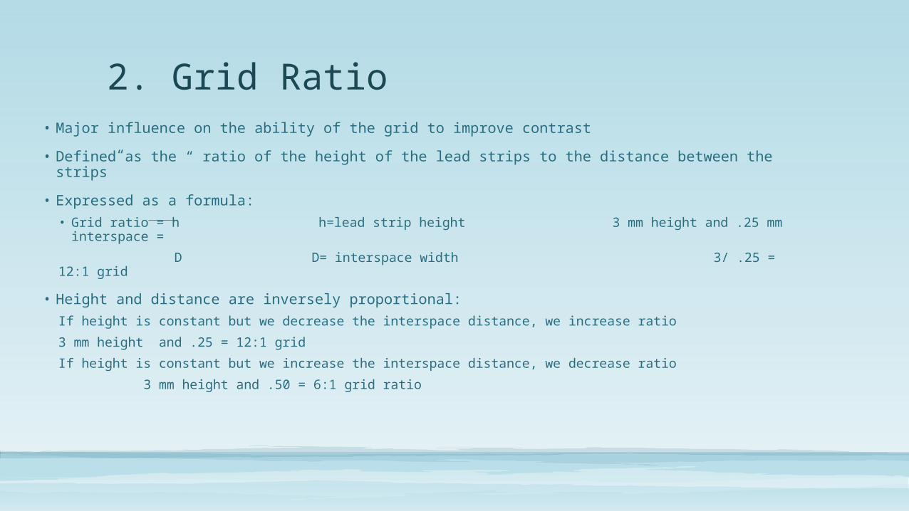
2. Grid Ratio• Major influence on the ability of the grid to improve contrast
• Defined as the “ ratio of the height of the lead strips to the distance between the strips”
• Expressed as a formula:
• Grid ratio = h h=lead strip height 3 mm height and .25 mm interspace =
D D= interspace width 3/ .25 = 12:1 grid
• Height and distance are inversely proportional:
If height is constant but we decrease the interspace distance, we increase ratio
3 mm height and .25 = 12:1 grid
If height is constant but we increase the interspace distance, we decrease ratio
3 mm height and .50 = 6:1 grid ratio
Comparing grid ratios• Higher grid ratios allow less
scatter to pass through- more effective at removing scatter
• Disadvantage to high grid ratio: must be more precise positioning of grid so primary isn’t absorbed – higher grid error

3. Grid Frequency• The number of grid lines per inch or cm
• Higher grid frequencies have thinner lead strips
• Range from 60-200 lines/inch
• Most common 85-103 lines / inch
• Very high frequencies 178-200 lines/inch are common for digital to minimize grid lines on image( because digital is more sensitive)
Grid Ratio and Grid Frequency• The combination of the two variable will determine the total quantity
of lead in the grid.
• Lead content is the most important in determining grid efficiency
• Lead content is greater in a grid with high radio and lower frequency – because the strips will be thicker in lower frequency
Grid Patterns: 2 types1. Linear grids- lead runs in one direction
• Most common- used in x-ray table
• Allow for tube angle along the direction of the lines ( long axis) – head to feet • Can have short axis grids- helpful for Port CXR where gird is place crosswise.
2. Criss-crossed or cross hatched- lead strips run at right angles • Do not allow for tube angle
• Limited applications
• Grid Cut-off- can occur with ANY grid • when the lead strips “cut-off” or absorb the primary beam- not allowing for it to
reach IR- no image in that area of the IR

Grid types1. Parallel – least common
2. Focused
1. Parallel grids• Lead and interspace run parallel to each other
• will never intersect
• Strips do not coincide with divergence of the beam • Absorb primary beam as a result-more along lateral edges
• Worse at short SIDs
• Better at long SIDs because beam is more straight
2. Focused Grid • Lead and interspace are still parallel but are angle to match
the divergence of the beam at different distances
• Would eventually intersect at a convergence line• The distance from the face of the grid to the point of
convergence is called grid radius
• Tube must be located across the convergence line
• Focused grids are grouped by focal ranges ( distances) 60-72 inch focus, 30-48 inch focus – grid will be marked • Lower grid ratios allow for greater latitude in tube alignment
• Higher grid ratios proper tube alignment is critical
Grid Uses • Stationary
• Come in various sizes to match cassette size
• Grid lines are more noticeable • Low frequency grids( thicker strips) worse than high frequency ( thinner strips)
• Used with portable or in rooms when patient is not on x-ray table- gurney or hosp bed
• Grid cassettes- for film/screen- grid was build into cassette
• Mounted moving- AKA Bucky• Mounted below table top ( or upright holder ) and hold cassette in place below (behind) the
grid
• Moves during exposure so grid lines will be blurred and not seen
• Larger than largest cassette size used in machine
• Grid lines run along the axis of table ( head to foot)
• Movement moves the grid at right angles to the grid- side to side
• Two movement types• Reciprocating- side to side- motor driven
• Oscillating- circular movement- electromagnet driven

Grid Selection• Made in equipment purchase- not normally interchangeable
• Stationary grids will be selected by size/ focus/ grid ratio
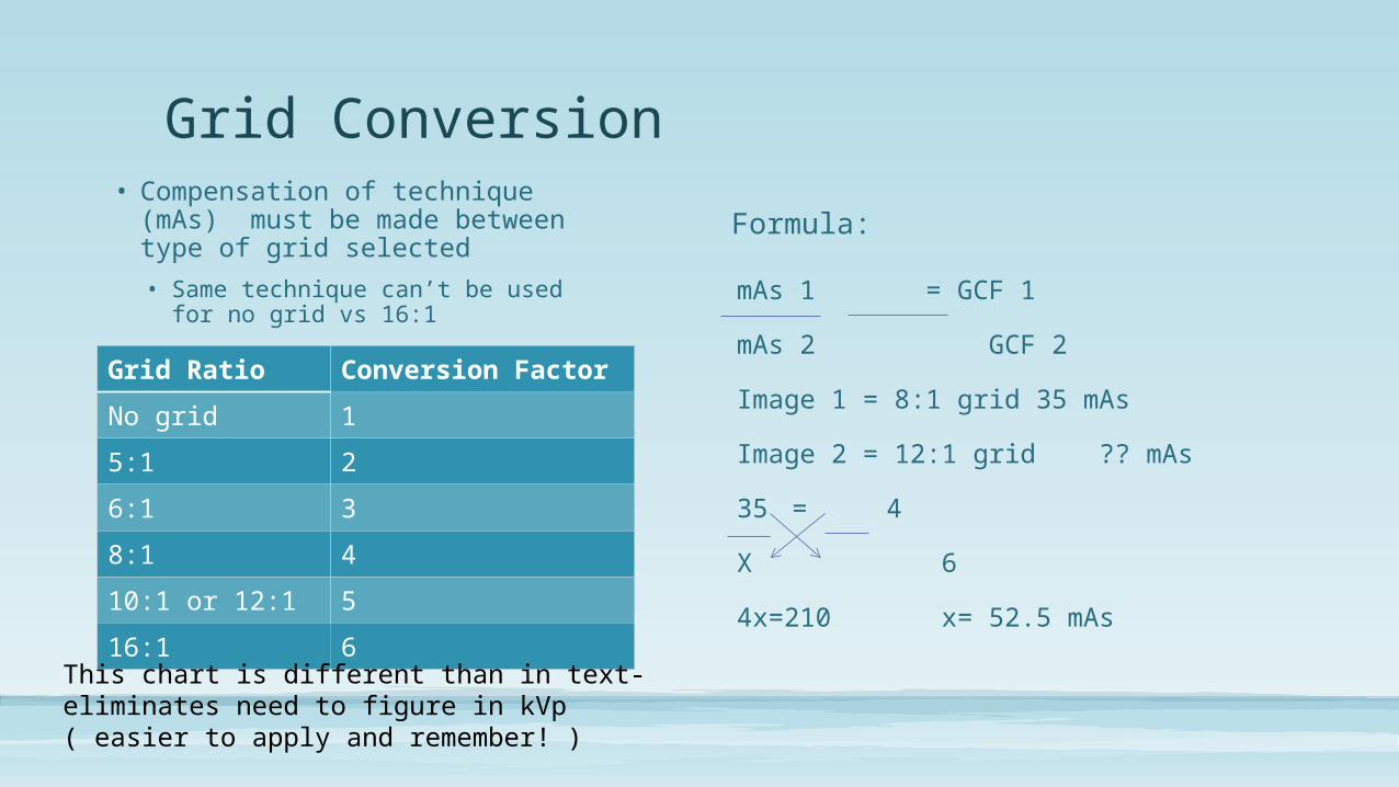
• Compensation of technique (mAs) must be made between type of grid selected
• Same technique can’t be used for no grid vs 16:1
Formula:
mAs 1 = GCF 1
mAs 2 GCF 2
Image 1 = 8:1 grid 35 mAs
Image 2 = 12:1 grid ?? mAs
35 = 4
X 6
4x=210 x= 52.5 mAs
Grid Conversion
Grid Ratio Conversion Factor
No grid 1
5:1 2
6:1 3
8:1 4
10:1 or 12:1 5
16:1 6
This chart is different than in text- eliminates need to figure in kVp ( easier to apply and remember! )
Grid Performance Evaluation• The measuring of a grid in cleanup or removing scatter
• Determined by two factors:
1. Selectivity
2. Contrast improvement ability
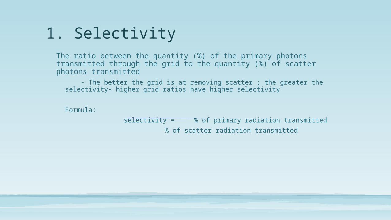
1. SelectivityThe ratio between the quantity (%) of the primary photons transmitted through the grid to the quantity (%) of scatter photons transmitted
- The better the grid is at removing scatter ; the greater the selectivity- higher grid ratios have higher selectivity
Formula:
selectivity = % of primary radiation transmitted
% of scatter radiation transmitted
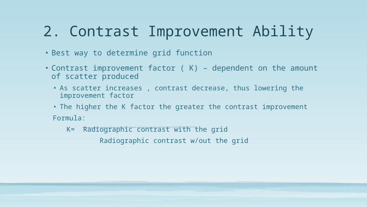
2. Contrast Improvement Ability• Best way to determine grid function
• Contrast improvement factor ( K) – dependent on the amount of scatter produced
• As scatter increases , contrast decrease, thus lowering the improvement factor
• The higher the K factor the greater the contrast improvement
Formula:
K= Radiographic contrast with the grid
Radiographic contrast w/out the grid
Grid Errors• Result of improper use
• More frequent with focused grids- tube must be centered and at correct SID
• Also has tube side and IR side
• Types of Errors
• Off- Level
• Off-Center
• Off-Focus
• Upside-down
• Moiré Effect
Off-Level• Occurs when tube is angled across the long axis of the grid strips
• Result of improper tube or grid position
• Most common with stationary grid- portable procedures
• Result
• Absorption of primary beam & decrease in overall exposure – light image
Off-Center• When tube is not centered to grid
• Does not line up with divergence of beam
• The greater degree of lateral off-centering the greater the cut-off
• Result :
• Decreased exposure across entire image ( light image)

Off-Focus• When a grid is used at incorrect
SID
• Higher grid ratios require greater accuracy to prevent cutoff
• Result:
• Grid cutoff along the peripheral edges of the image
Upside-Down• Focused grids have an identified tube
side
• Result:
• If used upside-down- severe peripheral grid cut-off will occur
The Moire Effect• Occurs with digital image receptors when grid lines are captured and
scanned parallel to the scan lines of the imaging plate reader
• Grid lines run parallel with the laser
• Happens with stationary grids- ran across short axis
• Corrected by high-frequency grids w/ 103 lines per inch or higher
References sheet for all documents
Alternate to Grid• Restricting beam size
• Compress body part- compression band
• Air-Gap Technique
• Increased OID – same amount of scatter will leave patient , but won’t reach patient
• 10” air gap has similar clean-up of 15:1 grid

This workforce solution was funded by a grant awarded by the U.S. Department of Labor's Employment and Training Administration. The solution was created by the grantee and does not necessarily reflect the official position of the U.S. Department of Labor. The Department of Labor makes no guarantees, warranties, or assurances of any kind, express or implied, with respect to such information, including any information on linked sites and including, but not limited to, accuracy of the information or its completeness, timeliness, usefulness, adequacy, continued availability, or ownership.