r3g630-ap01-01 operatinginstructions 1...
TRANSCRIPT
Operating instructionsR3G630-AP01-01Tr
ansl
atio
n of
the
orig
inal
ope
ratin
g in
stru
ctio
ns
ebm-papst Mulfingen GmbH & Co. KGBachmühle 2D-74673 MulfingenPhone +49 (0) 7938 81-0Fax +49 (0) 7938 [email protected]
CONTENTS
1. SAFETY REGULATIONS AND INFORMATION
11. SAFETY REGULATIONS AND INFORMATION
Read these operating instructions carefully before starting work on thedevice. Observe the following warnings to prevent malfunctions ordanger to persons.These operating instructions are to be regarded as part of the device.The device is only to be sold or passed on together with the operatinginstructions.These operating instructions may be duplicated and distributed to informabout potential dangers and their prevention.
1.1 Hazard levels for warnings11.1 Hazard levels for warnings
These operating instructions use the following hazard levels to indicatepotentially hazardous situations and important safety regulations:
DANGERIndicates an imminently hazardous situation which will result indeath or serious injury if the specified actions are not taken.Compliance with the instructions is imperative.
WARNINGIndicates a potentially hazardous situation which can result indeath or serious injury if the specified actions are not taken.Exercise extreme caution while working.
CAUTIONIndicates a potentially hazardous situation which can result inminor or moderate injury or damage to property if the specifiedactions are not taken.
NOTEA potentially harmful situation can occur and, if not avoided, canlead to property damage.
1.2 Staff qualifications
11.2 Staff qualifications
The device may only be transported, unpacked, installed, operated,maintained and otherwise used by suitably qualified, trained andauthorized technical staff.Only authorized specialists are permitted to install the device, to carryout a test run and to perform work on the electrical installation.
1.3 Basic safety rules
11.3 Basic safety rules
The safety hazards associated with the device must be assessed againfollowing installation in the final product.The locally applicable industrial safety regulations are always to beobserved when working on the device.Keep the workplace clean and tidy. Untidiness in the work areaincreases the risk of accidents.Note the following when working on the device:
; Do not perform any modifications, additions or conversions on thedevice without the approval of ebm-papst.
1.4 Voltage
11.4 Voltage
; Check the device's electrical equipment at regular intervals; seeChapter 6.3 Safety inspection.
; Replace loose connections and defective cables immediately.
DANGERElectrically charged deviceRisk of electric shock
→ When working on an electrically charged device, stand on arubber mat.
21.5 Safety and protective features21.6 Electromagnetic radiation21.7 Mechanical movement21.8 Emissions21.9 Hot surface21.10 Storage
32. INTENDED USE
43. TECHNICAL DATA43.1 Product drawing63.2 Nominal data63.3 Data according to Commission Regulation (EU) 327/201163.4 Technical description73.5 Mounting data73.6 Transport and storage conditions73.7 Electromagnetic compatibility
74. CONNECTION AND STARTUP74.1 Mechanical connection74.2 Electrical connection84.3 Connection in terminal box104.4 Factory settings114.5 Connection diagram124.6 Checking connections124.7 Switching on the device124.8 Switching off the device
125. INTEGRATED PROTECTIVE FEATURES
136. MAINTENANCE, MALFUNCTIONS, POSSIBLECAUSES AND REMEDIES
136.1 Vibration testing146.2 Cleaning146.3 Safety inspection146.4 Disposal
Item no. 51092-5-9970 · ENU · Change 90396 · Approved 2016-09-21 · Page 1 / 15
ebm-papst Mulfingen GmbH & Co. KG · Bachmühle 2 · D-74673 Mulfingen · Phone +49 (0) 7938 81-0 · Fax +49 (0) 7938 81-110 · [email protected] · www.ebmpapst.com
Operating instructionsR3G630-AP01-01Tr
ansl
atio
n of
the
orig
inal
ope
ratin
g in
stru
ctio
ns
WARNINGLive terminals and connections even with deviceswitched offElectric shock
→ Wait five minutes after disconnecting the voltage at all polesbefore opening the device.
CAUTIONIn the event of a fault, the rotor and the impeller will beenergizedThe rotor and the impeller have basic insulation.
→ Do not touch the rotor and impeller once installed.
CAUTIONIf control voltage or a stored speed set value is applied,the motor will restart automatically, e.g. after a powerfailure.Risk of injury
→ Keep out of the device’s danger zone.# When working onthe device, switch off the line voltage and ensure that itcannot be switched back on.
→ Wait until the device comes to a stop.
→ After working on the device, remove any tools or otherobjects from the device.
1.5 Safety and protective features
DANGERProtective device missing and protective device notfunctioningWithout a protective device there is a risk of serious injury, forinstance if the hands reach or are sucked into the device duringoperation.
→ Operate the device only with a fixed protective device andguard grille.
→ The fixed protective device must be able to withstand thekinetic energy of a fan blade that becomes detached atmaximum speed. There must not be any gaps which it ispossible to reach into with the fingers, for example.
→ The device is a built-in component. As the operator, youare responsible for ensuring that the device is securedadequately.
→ Stop the device immediately if you notice a missing orineffective protective device.
1.6 Electromagnetic radiation
Interference from electromagnetic radiation is possible, e.g. in conjunctionwith open- and closed-loop control devices.If impermissible radiation levels occur following installation, appropriateshielding measures have to be taken by the user.
NOTEElectrical or electromagnetic interference after installingthe device in customer equipment.
→ Verify that the entire setup is EMC-compliant.
1.7 Mechanical movement
DANGERRotating deviceRisk of injury to body parts coming into contact with the rotor orthe impeller.
→ Secure the device against accidental contact.
→ Before working on the system/machine, wait until allparts have come to a standstill.
DANGEREjected partsMissing protective devices may cause balancing weights orbroken fan blades to be ejected and cause injuries.
→ Take appropriate safety measures.
WARNINGRotating deviceLong hair and dangling items of clothing, jewelry and the likecan become entangled and be pulled into the device. Injuriescan result.
→ Do not wear any loose-fitting or dangling clothing or jewelrywhile working on rotating parts.
→ Protect long hair with a cap.
1.8 Emissions
WARNINGDepending on the installation and operating conditions,the sound pressure level may exceed 70 dB(A).Risk of noise-induced hearing loss
→ Take appropriate technical safety measures.
→ Protect operating personnel with appropriate safetyequipment such as hearing protection.
→ Also observe the requirements of local agencies.
1.9 Hot surface
CAUTIONHigh temperature on electronics housingRisk of burns
→ Ensure sufficient protection against accidental contact.
1.10 Storage
; Store the device, partially or fully assembled, in a dry place,protected against the weather and free from vibration, in the originalpackaging in a clean environment.
; Protect the device against environmental effects and dirt until finalinstallation.
; We recommend storing the device for no longer than one year inorder to guarantee trouble-free operation and the longest possibleservice life.
; Even devices explicitly intended for outdoor use are to be stored asdescribed prior to commissioning.
; Maintain the storage temperature, seeChapter 3.6 Transport and storage conditions.
; Make sure that all cable glands are fitted with dummy plugs.
Item no. 51092-5-9970 · ENU · Change 90396 · Approved 2016-09-21 · Page 2 / 15
ebm-papst Mulfingen GmbH & Co. KG · Bachmühle 2 · D-74673 Mulfingen · Phone +49 (0) 7938 81-0 · Fax +49 (0) 7938 81-110 · [email protected] · www.ebmpapst.com
Operating instructionsR3G630-AP01-01Tr
ansl
atio
n of
the
orig
inal
ope
ratin
g in
stru
ctio
ns
2. INTENDED USE
The device is exclusively designed as a built-in device for conveyingair according to its technical data.Any other usage above and beyond this does not conform with theintended purpose and constitutes misuse of the device.Customer equipment must be capable of withstanding the mechanicaland thermal stresses that can arise from this product. This applies for theentire service life of the equipment in which this product is installed.
Intended use also includes
● Using the device only in power systems with grounded neutral (TN/TT power systems).
● The device is to be used in networks with network qualitycharacteristics as per EN 50160.
● Using the device only in stationary systems.
● Performing all maintenance work.
● Conveying air at an ambient air pressure between 800 mbar and1050 mbar.
● Using the device within the permitted ambient temperature range; seeChapter 3.6 Transport and storage conditions andChapter 3.2 Nominal data.
● Operating the device with all protective devices.
● Following the operating instructions.
Improper use
In particular, operating the device in the following ways is prohibited andcould be hazardous:
● Operating the device in an unbalanced state, e.g. due to dirt depositsor ice formation.
● Resonant operation, operation with severe vibration. This alsoincludes vibration transmitted to the fan from the customer installation.
● Operation in medical equipment with a life-sustaining or life-supportfunction.
● Conveying solids in the flow medium.
● Painting the device
● Connections (e.g. screws) coming loose during operation.
● Opening the terminal box during operation.
● Conveying air that contains abrasive particles.
● Conveying highly corrosive air, e.g. salt spray. Exception: devicesdesigned for salt spray and correspondingly protected.
● Conveying air with high dust content, e.g. suctioning off sawdust.
● Operating the device close to flammable materials or components.
● Operating the device in an explosive atmosphere.
● Using the device as a safety component or to perform safety-relatedfunctions.
● Operation with completely or partially disassembled or manipulatedprotective devices.
● In addition, all applications not listed among the intended uses.
Item no. 51092-5-9970 · ENU · Change 90396 · Approved 2016-09-21 · Page 3 / 15
ebm-papst Mulfingen GmbH & Co. KG · Bachmühle 2 · D-74673 Mulfingen · Phone +49 (0) 7938 81-0 · Fax +49 (0) 7938 81-110 · [email protected] · www.ebmpapst.com
Operating instructionsR3G630-AP01-01Tr
ansl
atio
n of
the
orig
inal
ope
ratin
g in
stru
ctio
ns
3. TECHNICAL DATA
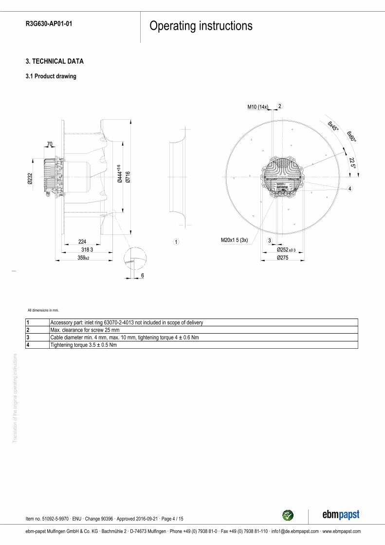
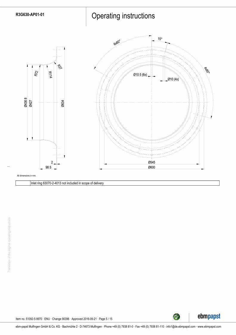
3.1 Product drawing
All dimensions in mm.
1 Accessory part: inlet ring 63070-2-4013 not included in scope of delivery2 Max. clearance for screw 25 mm3 Cable diameter min. 4 mm, max. 10 mm, tightening torque 4 ± 0.6 Nm4 Tightening torque 3.5 ± 0.5 Nm
Item no. 51092-5-9970 · ENU · Change 90396 · Approved 2016-09-21 · Page 4 / 15
ebm-papst Mulfingen GmbH & Co. KG · Bachmühle 2 · D-74673 Mulfingen · Phone +49 (0) 7938 81-0 · Fax +49 (0) 7938 81-110 · [email protected] · www.ebmpapst.com
Operating instructionsR3G630-AP01-01Tr
ansl
atio
n of
the
orig
inal
ope
ratin
g in
stru
ctio
ns
All dimensions in mm.
Inlet ring 63070-2-4013 not included in scope of delivery
Item no. 51092-5-9970 · ENU · Change 90396 · Approved 2016-09-21 · Page 5 / 15
ebm-papst Mulfingen GmbH & Co. KG · Bachmühle 2 · D-74673 Mulfingen · Phone +49 (0) 7938 81-0 · Fax +49 (0) 7938 81-110 · [email protected] · www.ebmpapst.com
Operating instructionsR3G630-AP01-01Tr
ansl
atio
n of
the
orig
inal
ope
ratin
g in
stru
ctio
ns
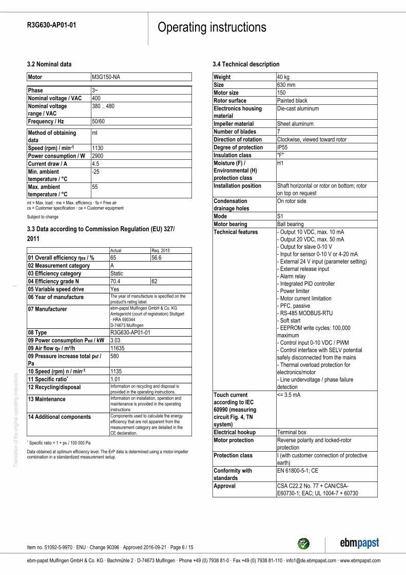
3.2 Nominal data
Motor M3G150-NA
Phase 3~Nominal voltage / VAC 400Nominal voltagerange / VAC
380 .. 480
Frequency / Hz 50/60
Method of obtainingdata
ml
Speed (rpm) / min-1 1130Power consumption / W 2900Current draw / A 4.5Min. ambienttemperature / °C
-25
Max. ambienttemperature / °C
55
ml = Max. load · me = Max. efficiency · fa = Free aircs = Customer specification · ce = Customer equipment
Subject to change
3.3 Data according to Commission Regulation (EU) 327/2011
Actual Req. 2015
01 Overall efficiency ηes / % 65 56.602 Measurement category A03 Efficiency category Static04 Efficiency grade N 70.4 6205 Variable speed drive Yes06 Year of manufacture The year of manufacture is specified on the
product's rating label.
07 Manufacturer ebm-papst Mulfingen GmbH & Co. KGAmtsgericht (court of registration) Stuttgart· HRA 590344D-74673 Mulfingen
08 Type R3G630-AP01-0109 Power consumption Ped / kW 3.0309 Air flow qv / m³/h 1163509 Pressure increase total psf /Pa
580
10 Speed (rpm) n / min-1 113511 Specific ratio* 1.0112 Recycling/disposal Information on recycling and disposal is
provided in the operating instructions.
13 Maintenance Information on installation, operation andmaintenance is provided in the operatinginstructions.
14 Additional components Components used to calculate the energyefficiency that are not apparent from themeasurement category are detailed in theCE declaration.
* Specific ratio = 1 + pfs / 100 000 Pa
Data obtained at optimum efficiency level. The ErP data is determined using a motor-impellercombination in a standardized measurement setup.
3.4 Technical description
Weight 40 kgSize 630 mmMotor size 150Rotor surface Painted blackElectronics housingmaterial
Die-cast aluminum
Impeller material Sheet aluminumNumber of blades 7Direction of rotation Clockwise, viewed toward rotorDegree of protection IP55Insulation class "F"Moisture (F) /Environmental (H)protection class
H1
Installation position Shaft horizontal or rotor on bottom; rotoron top on request
Condensationdrainage holes
On rotor side
Mode S1Motor bearing Ball bearingTechnical features - Output 10 VDC, max. 10 mA
- Output 20 VDC, max. 50 mA- Output for slave 0-10 V- Input for sensor 0-10 V or 4-20 mA- External 24 V input (parameter setting)- External release input- Alarm relay- Integrated PID controller- Power limiter- Motor current limitation- PFC, passive- RS-485 MODBUS-RTU- Soft start- EEPROM write cycles: 100,000maximum- Control input 0-10 VDC / PWM- Control interface with SELV potentialsafely disconnected from the mains- Thermal overload protection forelectronics/motor- Line undervoltage / phase failuredetection
Touch currentaccording to IEC60990 (measuringcircuit Fig. 4, TNsystem)
<= 3.5 mA
Electrical hookup Terminal boxMotor protection Reverse polarity and locked-rotor
protectionProtection class I (with customer connection of protective
earth)Conformity withstandards
EN 61800-5-1; CE
Approval CSA C22.2 No. 77 + CAN/CSA-E60730-1; EAC; UL 1004-7 + 60730
Item no. 51092-5-9970 · ENU · Change 90396 · Approved 2016-09-21 · Page 6 / 15
ebm-papst Mulfingen GmbH & Co. KG · Bachmühle 2 · D-74673 Mulfingen · Phone +49 (0) 7938 81-0 · Fax +49 (0) 7938 81-110 · [email protected] · www.ebmpapst.com
Operating instructionsR3G630-AP01-01Tr
ansl
atio
n of
the
orig
inal
ope
ratin
g in
stru
ctio
ns
With regard to cyclic speed loads, note that the rotating parts ofthe device are designed for a maximum of one million loadcycles. If you have special questions, consult ebm-papst forsupport.
; Use the device in accordance with its degree of protection.
Information on surface quality
The surfaces of the products conform to the generally applicable industrialstandard. The surface quality may change during the production period.This has no effect on strength, dimensional stability and dimensionalaccuracy.The color pigments in the paints used perceptibly react to UV light overthe course of time. This does not however in any way affect thetechnical properties of the products. The product is to be protected againstUV radiation to prevent the formation of patches and fading. Changes incolor are not a reason for complaint and are not covered by the warranty.
3.5 Mounting data
; Secure the screws against unintentional loosening (e.g. use self-locking screws).
Strength class ofscrews
8.8
Any further mounting data required can be taken from the productdrawing or Section Chapter 4.1 Mechanical connection.
3.6 Transport and storage conditions
Max. permittedambient temp. formotor (transport/storage)
+80 °C
Min. permittedambient temp. formotor (transport/storage)
-40 °C
3.7 Electromagnetic compatibility
If several devices are switched in parallel on the supply sideso that the line current of the arrangement is in the range of 16-75 A, then this arrangement conforms to IEC 61000-3-12provided that the short-circuit power Ssc at the connection pointof the customer system to the public power system is greaterthan or equal to 120 times the rated output of the arrangement.It is the responsibility of the installation engineer or operator/owner of the device to ensure, if necessary after consultationwith the network operator, that this device is only connected toa connection point with a Ssc value that is greater than or equalto 120 times the rated output of the arrangement.
4. CONNECTION AND STARTUP
4.1 Mechanical connection
CAUTIONCutting and crushing hazard when removing fan frompackaging
→ Carefully remove the device from its packaging, by the fanimpeller. Strictly avoid shocks.
→ Wear safety shoes and cut-resistant safety gloves.
CAUTIONDevice weighs over 25 kg! Heavy load when unpackingdevice.Risk of physical injury, such as back injuries.
→ Use suitable hoisting equipment to remove the device fromits packaging.
NOTEDamage to the device from vibrationBearing damage, shorter service life
→ The fan must not be subjected to force or excessive vibrationfrom sections of the installation. #If the fan is connected to airducts, the connection should be isolated from vibration, e.g.using compensators or similar elements. #Ensure stress-freeattachment of the fan to the substructure.
; Check the device for transport damage. Damaged devices are not tobe installed.
; Install the undamaged device in accordance with your application.
CAUTIONPossible damage to the deviceIf the device slips during installation, serious damage can result.
→ Ensure that the device is securely positioned at its place ofinstallation until all fastening screws have been tightened.
● The fan must not be strained on fastening.
4.2 Electrical connection
DANGERVoltage on the deviceElectric shock
→ Always connect a protective earth first.
→ Check the protective earth.
DANGERFaulty insulationRisk of fatal injury from electric shock
→ Use only cables that meet the specified installationregulations for voltage, current, insulation material, capacity,etc.
→ Route cables so that they cannot be touched by anyrotating parts.
DANGERElectrical charge (>50 µC) between phase conductor andprotective earth connection after switching off supplywith multiple devices connected in parallel.Electric shock, risk of injury
→ Ensure sufficient protection against accidental contact.Before working on the electrical hookup, short the supplyand PE connections.
Item no. 51092-5-9970 · ENU · Change 90396 · Approved 2016-09-21 · Page 7 / 15
ebm-papst Mulfingen GmbH & Co. KG · Bachmühle 2 · D-74673 Mulfingen · Phone +49 (0) 7938 81-0 · Fax +49 (0) 7938 81-110 · [email protected] · www.ebmpapst.com
Operating instructionsR3G630-AP01-01Tr
ansl
atio
n of
the
orig
inal
ope
ratin
g in
stru
ctio
ns
CAUTIONVoltageThe fan is a built-in component and has no disconnecting switch.
→ Only connect the fan to circuits that can be switched off withan all-pole disconnection switch.
→ When working on the fan, secure the system/machine inwhich the fan is installed so as to prevent it from beingswitched back on.
NOTEDevice malfunctions possibleRoute the device's control lines separately from the supply line.
→ Maintain the greatest possible clearance.Recommendation: clearance > 10 cm (separate cablerouting)
NOTEWater ingress into wires or cablesWater ingress at the customer end of the cable can damage thedevice.
→ Make sure the end of the cable is connected in a dryenvironment.
Only connect the device to circuits that can be switched off withan all-pole disconnection switch.
4.2.1 Requirements
; Check whether the information on the nameplate matches theconnection data.
; Before connecting the device, make sure the power supply matchesthe device voltage.
; Only use cables designed for the current level indicated on thenameplate.For determining the cross-section, note the sizing criteria accordingto EN 61800-5-1. The protective earth must have a cross-sectionequal to or greater than that of the phase conductor.We recommend the use of 105 °C cables. Ensure that the minimumcable cross-section is at leastAWG 26 / 0.13 mm².
Protective earth contact resistance according to EN 61800-5-1
Compliance with the resistance specifications according to EN 61800-5-1 for the protective earth connection circuit must be verified in the endapplication. Depending on the installation situation, it may be necessaryto connect an additional protective earth conductor by way of the extraprotective earth terminal provided on the device. The protective earthterminal is located on the housing and provided with a protective earthsymbol and a hole.
4.2.2 Supply connection and fuses
Assignment of supply cable cross-sections and their required fuses (lineprotection only, no equipment protection).
Nominalvoltage
Fuse Automaticcircuitbreaker
Cablecross-section
Cablecross-section
VDE UL VDE mm² *AWG3/PE AC380-480VAC
16 A 15 A C16A 1.5 16
3/PE AC380-480VAC
20 A 20 A C20A 2.5 14
3/PE AC380-480VAC
25 A 25 A C25A 4.0 12
* AWG = American Wire Gauge
4.2.3 Reactive currents
Because of the EMC filter integrated for compliance with EMClimits (interference emission and immunity to interference),reactive currents can be measured in the supply line evenwhen the motor is at a standstill and the line voltage is switchedon.
● The values are typically in the range < 250 mA
● At the same time, the effective power in this operating state(operational readiness) is typically < 5 W.
4.2.4 Residual current circuit breaker (RCCB)
If the use of a residual current device (RCD) is required in yourinstallation, only AC/DC-sensitive residual current devices(type B or B+) are permissible. As with variable frequencydrives, residual current devices cannot provide personal safetywhile operating the device. When the device power supply isswitched on, pulsed charging currents from the capacitors in theintegrated EMC filter can lead to the instant tripping of residualcurrent devices. We recommend the use of residual currentcircuit breakers (RCCB) with a trip threshold of 300 mA anddelayed tripping (super-resistant, characteristic K).
4.2.5 Leakage current
For asymmetrical power systems or if a phase fails, theleakage current can increase to a multiple of the nominal value.
4.2.6 Locked-rotor protection
Due to the locked-rotor protection, the starting current (LRA) isequal to or less than the nominal current (FLA).
4.3 Connection in terminal box
4.3.1 Preparing cables for connection
Only strip the cable as far as necessary, ensuring that the cable gland issealed and there is no strain on the connections. For tightening torques,see Chapter 3.1 Product drawing.
NOTETightness and strain relief are dependent on the cableused.
→ This must be checked by the user.
Item no. 51092-5-9970 · ENU · Change 90396 · Approved 2016-09-21 · Page 8 / 15
ebm-papst Mulfingen GmbH & Co. KG · Bachmühle 2 · D-74673 Mulfingen · Phone +49 (0) 7938 81-0 · Fax +49 (0) 7938 81-110 · [email protected] · www.ebmpapst.com
Operating instructionsR3G630-AP01-01Tr
ansl
atio
n of
the
orig
inal
ope
ratin
g in
stru
ctio
ns
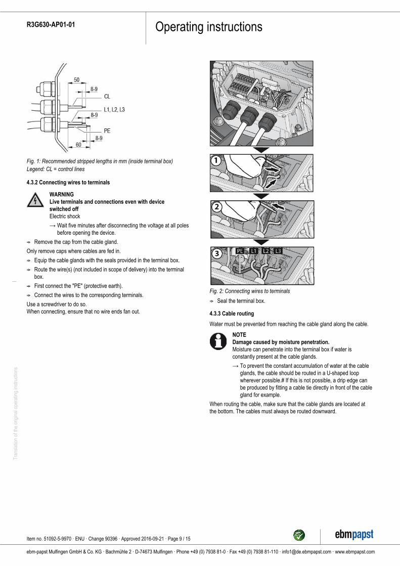
Fig. 1: Recommended stripped lengths in mm (inside terminal box)Legend: CL = control lines
4.3.2 Connecting wires to terminals
WARNINGLive terminals and connections even with deviceswitched offElectric shock
→ Wait five minutes after disconnecting the voltage at all polesbefore opening the device.
; Remove the cap from the cable gland.
Only remove caps where cables are fed in.
; Equip the cable glands with the seals provided in the terminal box.
; Route the wire(s) (not included in scope of delivery) into the terminalbox.
; First connect the "PE" (protective earth).
; Connect the wires to the corresponding terminals.
Use a screwdriver to do so.When connecting, ensure that no wire ends fan out.
Fig. 2: Connecting wires to terminals
; Seal the terminal box.
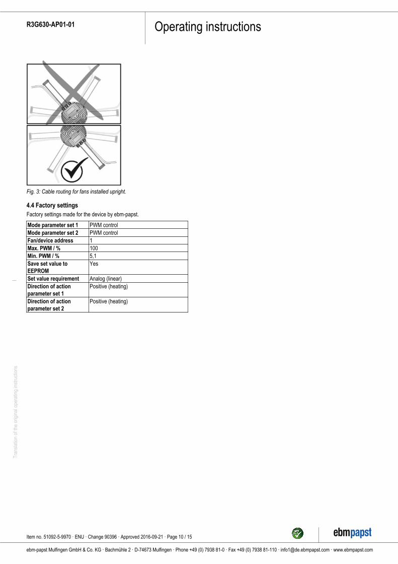
4.3.3 Cable routing
Water must be prevented from reaching the cable gland along the cable.
NOTEDamage caused by moisture penetration.Moisture can penetrate into the terminal box if water isconstantly present at the cable glands.
→ To prevent the constant accumulation of water at the cableglands, the cable should be routed in a U-shaped loopwherever possible.# If this is not possible, a drip edge canbe produced by fitting a cable tie directly in front of the cablegland for example.
When routing the cable, make sure that the cable glands are located atthe bottom. The cables must always be routed downward.
Item no. 51092-5-9970 · ENU · Change 90396 · Approved 2016-09-21 · Page 9 / 15
ebm-papst Mulfingen GmbH & Co. KG · Bachmühle 2 · D-74673 Mulfingen · Phone +49 (0) 7938 81-0 · Fax +49 (0) 7938 81-110 · [email protected] · www.ebmpapst.com
Operating instructionsR3G630-AP01-01Tr
ansl
atio
n of
the
orig
inal
ope
ratin
g in
stru
ctio
ns
Fig. 3: Cable routing for fans installed upright.
4.4 Factory settingsFactory settings made for the device by ebm-papst.
Mode parameter set 1 PWM controlMode parameter set 2 PWM controlFan/device address 1Max. PWM / % 100Min. PWM / % 5,1Save set value toEEPROM
Yes
Set value requirement Analog (linear)Direction of actionparameter set 1
Positive (heating)
Direction of actionparameter set 2
Positive (heating)
Item no. 51092-5-9970 · ENU · Change 90396 · Approved 2016-09-21 · Page 10 / 15
ebm-papst Mulfingen GmbH & Co. KG · Bachmühle 2 · D-74673 Mulfingen · Phone +49 (0) 7938 81-0 · Fax +49 (0) 7938 81-110 · [email protected] · www.ebmpapst.com
Operating instructionsR3G630-AP01-01Tr
ansl
atio
n of
the
orig
inal
ope
ratin
g in
stru
ctio
ns
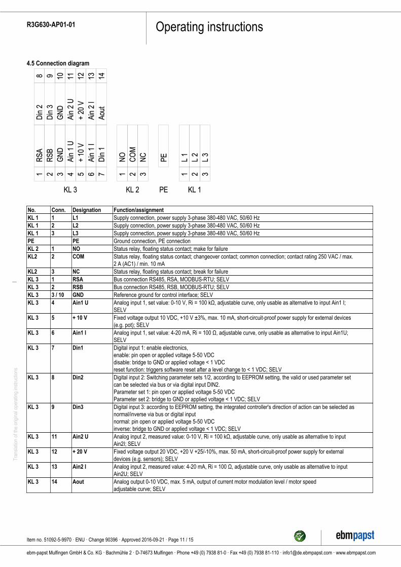
4.5 Connection diagram
No. Conn. Designation Function/assignmentKL 1 1 L1 Supply connection, power supply 3-phase 380-480 VAC, 50/60 HzKL 1 2 L2 Supply connection, power supply 3-phase 380-480 VAC, 50/60 HzKL 1 3 L3 Supply connection, power supply 3-phase 380-480 VAC, 50/60 HzPE PE Ground connection, PE connectionKL 2 1 NO Status relay, floating status contact; make for failureKL2 2 COM Status relay, floating status contact; changeover contact; common connection; contact rating 250 VAC / max.
2 A (AC1) / min. 10 mAKL2 3 NC Status relay, floating status contact; break for failureKL 3 1 RSA Bus connection RS485, RSA, MODBUS-RTU; SELVKL 3 2 RSB Bus connection RS485, RSB, MODBUS-RTU; SELVKL 3 3 / 10 GND Reference ground for control interface; SELVKL 3 4 Ain1 U Analog input 1, set value: 0-10 V, Ri = 100 kΩ, adjustable curve, only usable as alternative to input Ain1 I;
SELVKL 3 5 + 10 V Fixed voltage output 10 VDC, +10 V ±3%, max. 10 mA, short-circuit-proof power supply for external devices
(e.g. pot); SELVKL 3 6 Ain1 I Analog input 1, set value: 4-20 mA, Ri = 100 Ω, adjustable curve, only usable as alternative to input Ain1U;
SELVKL 3 7 Din1 Digital input 1: enable electronics,
enable: pin open or applied voltage 5-50 VDCdisable: bridge to GND or applied voltage < 1 VDCreset function: triggers software reset after a level change to < 1 VDC; SELV
KL 3 8 Din2 Digital input 2: Switching parameter sets 1/2, according to EEPROM setting, the valid or used parameter setcan be selected via bus or via digital input DIN2.Parameter set 1: pin open or applied voltage 5-50 VDCParameter set 2: bridge to GND or applied voltage < 1 VDC; SELV
KL 3 9 Din3 Digital input 3: according to EEPROM setting, the integrated controller's direction of action can be selected asnormal/inverse via bus or digital inputnormal: pin open or applied voltage 5-50 VDCinverse: bridge to GND or applied voltage < 1 VDC; SELV
KL 3 11 Ain2 U Analog input 2, measured value: 0-10 V, Ri = 100 kΩ, adjustable curve, only usable as alternative to inputAin2I; SELV
KL 3 12 + 20 V Fixed voltage output 20 VDC, +20 V +25/-10%, max. 50 mA, short-circuit-proof power supply for externaldevices (e.g. sensors); SELV
KL 3 13 Ain2 I Analog input 2, measured value: 4-20 mA, Ri = 100 Ω, adjustable curve, only usable as alternative to inputAin2U; SELV
KL 3 14 Aout Analog output 0-10 VDC, max. 5 mA, output of current motor modulation level / motor speedadjustable curve; SELV
Item no. 51092-5-9970 · ENU · Change 90396 · Approved 2016-09-21 · Page 11 / 15
ebm-papst Mulfingen GmbH & Co. KG · Bachmühle 2 · D-74673 Mulfingen · Phone +49 (0) 7938 81-0 · Fax +49 (0) 7938 81-110 · [email protected] · www.ebmpapst.com
Operating instructionsR3G630-AP01-01Tr
ansl
atio
n of
the
orig
inal
ope
ratin
g in
stru
ctio
ns
4.6 Checking connections
; Ensure isolation from supply (all phases).
; Make sure a restart is impossible
; Check the cables for proper fit.
; Screw the terminal box cover back on again. Terminal box tighteningtorque, see Chapter 3.1 Product drawing.
; Route the cables in the terminal box so that the terminal box covercloses without resistance.
; Use all screw plugs. Insert the screws by hand to avoid damage tothe threads.
; Make sure the terminal box is completely closed and sealed and thatall screws and cable glands have been properly tightened.
4.7 Switching on the device
The device may only be switched on if it has been installed properly andin accordance with its intended use, including the required safetymechanisms and professional electrical hookup. This also applies fordevices which have already been equipped with plugs and terminals orsimilar connectors by the customer.
WARNINGHot motor housingRisk of fire
→ Ensure that no combustible or flammable materials arelocated close to the fan.
; Before switching on, check the device for visible external damageand make sure the protective devices are functional.
; Check the fan's air flow paths for foreign matter and remove anyforeign matter found.
; Apply the nominal supply voltage.
; Start the device by changing the input signal.
NOTEDamage to the device from vibrationBearing damage, shorter service life
→ Low-vibration operation of the fan must be ensured over theentire speed control range. #Severe vibration can arise forinstance from inexpert handling, transportation damage andresultant imbalance or be caused by component or structuralresonance. #Speed ranges with excessively high vibrationlevels and possibly resonant frequencies must bedetermined in the course of fan commissioning. #Either runthrough the resonant range as quickly as possible withspeed control or find another remedy.# Operation withexcessively high vibration levels can lead to prematurefailure.
→ The maximum permissible vibration severity must notexceed 3.5 mm/s and should be checked at intervals of 6months. #It is to be measured at the motor mount at themotor support plate in all three 3 dimensions, see Chapter 6.Maintenance, malfunctions, possible causes and remedies.
4.8 Switching off the device
Switching off the device during operation:
; Switch off the device via the control input.
; Do not switch the motor (e.g. in cyclic operation) on and off via powersupply.
Switching off the device for maintenance:
; Switch off the device via the control input.
; Do not switch the motor (e.g. in cyclic operation) on and off via powersupply.
; Disconnect the device from the power supply.
; When disconnecting, be sure to disconnect the ground connection last.
5. INTEGRATED PROTECTIVE FEATURES
The integrated protective functions cause the motor to switch offautomatically in the event of the faults described in the table.
Fault Safety feature description/function
Rotor position detection error An automatic restart follows.Blocked rotor ; After the blockage is
removed, the motor restartsautomatically.
Line undervoltage (line voltageoutside of permitted nominalvoltage range)
; If the line voltage returns topermitted values, the motorrestarts automatically.
Phase failure A phase of the supply voltagefails for at least 5 s.; When all phases arecorrectly supplied again, themotor automatically restarts after10-40 s.
Item no. 51092-5-9970 · ENU · Change 90396 · Approved 2016-09-21 · Page 12 / 15
ebm-papst Mulfingen GmbH & Co. KG · Bachmühle 2 · D-74673 Mulfingen · Phone +49 (0) 7938 81-0 · Fax +49 (0) 7938 81-110 · [email protected] · www.ebmpapst.com
Operating instructionsR3G630-AP01-01Tr
ansl
atio
n of
the
orig
inal
ope
ratin
g in
stru
ctio
ns
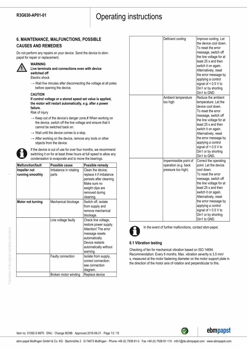
6. MAINTENANCE, MALFUNCTIONS, POSSIBLECAUSES AND REMEDIES
Do not perform any repairs on your device. Send the device to ebm-papst for repair or replacement.
WARNINGLive terminals and connections even with deviceswitched offElectric shock
→ Wait five minutes after disconnecting the voltage at all polesbefore opening the device.
CAUTIONIf control voltage or a stored speed set value is applied,the motor will restart automatically, e.g. after a powerfailure.Risk of injury
→ Keep out of the device’s danger zone.# When working onthe device, switch off the line voltage and ensure that itcannot be switched back on.
→ Wait until the device comes to a stop.
→ After working on the device, remove any tools or otherobjects from the device.
If the device is out of use for over four months, we recommendswitching it on for at least three hours at full speed to allow anycondensation to evaporate and to move the bearings.
Malfunction/fault Possible cause Possible remedyImpeller notrunning smoothly
Imbalance in rotatingparts
Clean the device;replace it if imbalancepersists after cleaning.Make sure noweight clips areremoved duringcleaning.
Motor not turning Mechanical blockage Switch off, isolatefrom supply andremove mechanicalblockage.
Line voltage faulty Check line voltage,restore power supply.Attention! The errormessage resetsautomatically.Device restartsautomatically withoutwarning.
Faulty connection Isolate from supply,correct connection;see connectiondiagram.
Broken motor winding Replace device
Deficient cooling Improve cooling. Letthe device cool down.To reset the errormessage, switch offthe line voltage for atleast 25 s and thenswitch it on again.Alternatively, resetthe error message byapplying a controlsignal of < 0.5 V toDin1 or by shortingDin1 to GND.
Ambient temperaturetoo high
Reduce the ambienttemperature. Let thedevice cool down.To reset the errormessage, switch offthe line voltage for atleast 25 s and thenswitch it on again.Alternatively, resetthe error message byapplying a controlsignal of < 0.5 V toDin1 or by shortingDin1 to GND.
Impermissible point ofoperation (e.g. backpressure too high)
Correct the operatingpoint. Let the devicecool down.To reset the errormessage, switch offthe line voltage for atleast 25 s and thenswitch it on again.Alternatively, resetthe error message byapplying a controlsignal of < 0.5 V toDin1 or by shortingDin1 to GND.
In the event of further malfunctions, contact ebm-papst.
6.1 Vibration testing
Checking of fan for mechanical vibration based on ISO 14694.Recommendation: Every 6 months. Max. vibration severity is 3.5 mm/s, measured at the motor fastening diameter on the motor support plate inthe direction of the motor axis of rotation and perpendicular to this.
Item no. 51092-5-9970 · ENU · Change 90396 · Approved 2016-09-21 · Page 13 / 15
ebm-papst Mulfingen GmbH & Co. KG · Bachmühle 2 · D-74673 Mulfingen · Phone +49 (0) 7938 81-0 · Fax +49 (0) 7938 81-110 · [email protected] · www.ebmpapst.com
Operating instructionsR3G630-AP01-01Tr
ansl
atio
n of
the
orig
inal
ope
ratin
g in
stru
ctio
ns
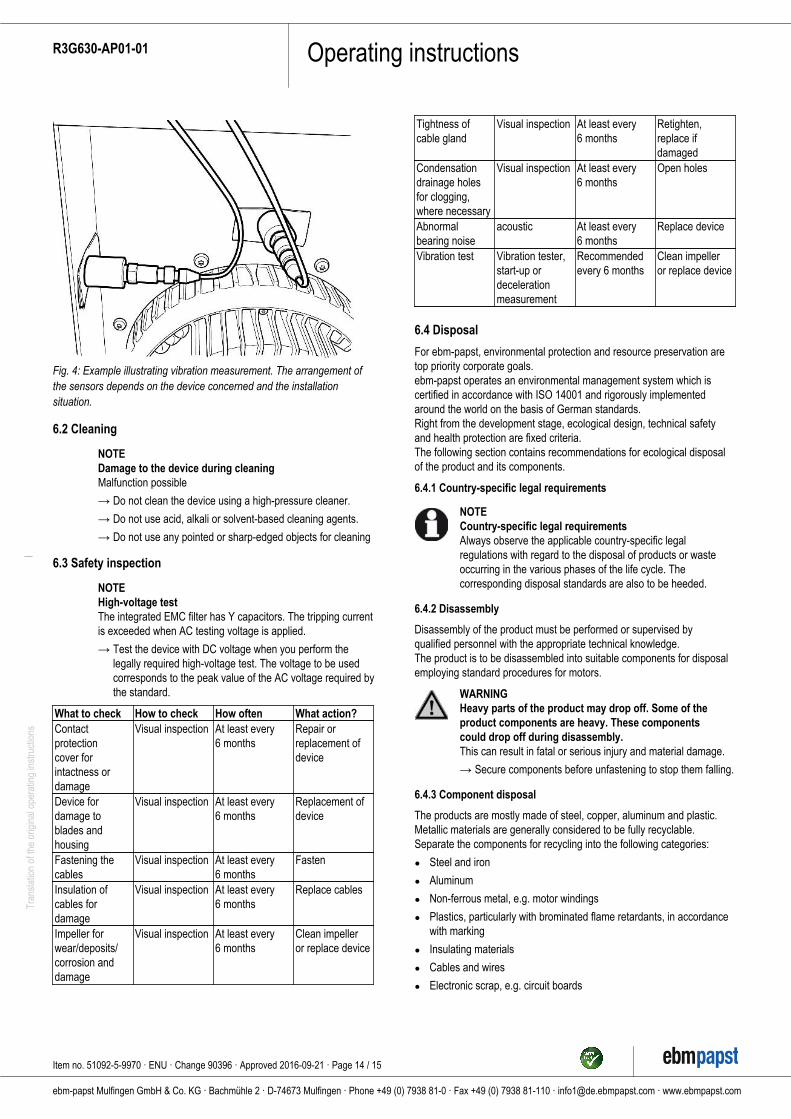
Fig. 4: Example illustrating vibration measurement. The arrangement ofthe sensors depends on the device concerned and the installationsituation.
6.2 Cleaning
NOTEDamage to the device during cleaningMalfunction possible
→ Do not clean the device using a high-pressure cleaner.
→ Do not use acid, alkali or solvent-based cleaning agents.
→ Do not use any pointed or sharp-edged objects for cleaning
6.3 Safety inspection
NOTEHigh-voltage testThe integrated EMC filter has Y capacitors. The tripping currentis exceeded when AC testing voltage is applied.
→ Test the device with DC voltage when you perform thelegally required high-voltage test. The voltage to be usedcorresponds to the peak value of the AC voltage required bythe standard.
What to check How to check How often What action?Contactprotectioncover forintactness ordamage
Visual inspection At least every6 months
Repair orreplacement ofdevice
Device fordamage toblades andhousing
Visual inspection At least every6 months
Replacement ofdevice
Fastening thecables
Visual inspection At least every6 months
Fasten
Insulation ofcables fordamage
Visual inspection At least every6 months
Replace cables
Impeller forwear/deposits/corrosion anddamage
Visual inspection At least every6 months
Clean impelleror replace device
Tightness ofcable gland
Visual inspection At least every6 months
Retighten,replace ifdamaged
Condensationdrainage holesfor clogging,where necessary
Visual inspection At least every6 months
Open holes
Abnormalbearing noise
acoustic At least every6 months
Replace device
Vibration test Vibration tester,start-up ordecelerationmeasurement
Recommendedevery 6 months
Clean impelleror replace device
6.4 Disposal
For ebm-papst, environmental protection and resource preservation aretop priority corporate goals.ebm-papst operates an environmental management system which iscertified in accordance with ISO 14001 and rigorously implementedaround the world on the basis of German standards.Right from the development stage, ecological design, technical safetyand health protection are fixed criteria.The following section contains recommendations for ecological disposalof the product and its components.
6.4.1 Country-specific legal requirements
NOTECountry-specific legal requirementsAlways observe the applicable country-specific legalregulations with regard to the disposal of products or wasteoccurring in the various phases of the life cycle. Thecorresponding disposal standards are also to be heeded.
6.4.2 Disassembly
Disassembly of the product must be performed or supervised byqualified personnel with the appropriate technical knowledge.The product is to be disassembled into suitable components for disposalemploying standard procedures for motors.
WARNINGHeavy parts of the product may drop off. Some of theproduct components are heavy. These componentscould drop off during disassembly.This can result in fatal or serious injury and material damage.
→ Secure components before unfastening to stop them falling.
6.4.3 Component disposal
The products are mostly made of steel, copper, aluminum and plastic.Metallic materials are generally considered to be fully recyclable.Separate the components for recycling into the following categories:
● Steel and iron
● Aluminum
● Non-ferrous metal, e.g. motor windings
● Plastics, particularly with brominated flame retardants, in accordancewith marking
● Insulating materials
● Cables and wires
● Electronic scrap, e.g. circuit boards
Item no. 51092-5-9970 · ENU · Change 90396 · Approved 2016-09-21 · Page 14 / 15
ebm-papst Mulfingen GmbH & Co. KG · Bachmühle 2 · D-74673 Mulfingen · Phone +49 (0) 7938 81-0 · Fax +49 (0) 7938 81-110 · [email protected] · www.ebmpapst.com
Operating instructionsR3G630-AP01-01Tr
ansl
atio
n of
the
orig
inal
ope
ratin
g in
stru
ctio
ns
Only ferrite magnets and not rare earth magnets are used in externalrotor motors from ebm-papst Mulfingen GmbH & Co. KG.
; Ferrite magnets can be disposed of in the same way as normal ironand steel.
Electrical insulating materials on the product, in cables and wires aremade of similar materials and are therefore to be treated in the samemanner.The materials concerned are as follows:
● Miscellaneous insulators used in the terminal box
● Power cables
● Cables for internal wiring
● Electrolytic capacitors
Dispose of electronic components employing the proper procedures forelectronic scrap.
→ Please contact ebm-papst for any other questions on disposal.
Item no. 51092-5-9970 · ENU · Change 90396 · Approved 2016-09-21 · Page 15 / 15
ebm-papst Mulfingen GmbH & Co. KG · Bachmühle 2 · D-74673 Mulfingen · Phone +49 (0) 7938 81-0 · Fax +49 (0) 7938 81-110 · [email protected] · www.ebmpapst.com