quick startup guide - docshare04.docshare.tipsdocshare04.docshare.tips/files/11858/118585867.pdf ·...
TRANSCRIPT
Version 1.3 07/01/1999 Page 1
Quick Startup Guide forSIMOVERT MASTERDRIVES
6SE70 MC
Motion Control
Section 1: Parameterization of Base Drive
Section 2: Servo Drive Tuning Procedure
Section 3: Technology Options Quick Setup Method
Version 1.3 07/01/1999 Page 2
We reserve the right to modify functions, technical data, standards, drawings and
parameters.
We have checked the contents of this document to ensure that they coincide with the
described hardware and software. However, deviations cannot be completely ruled-
out, so we cannot guarantee complete conformance. However, the information in this
document is regularly checked and the necessary corrections will be included in
subsequent editions. We are thankful for any recommendations or suggestions.
e-mail: [email protected]
Version 1.3 07/01/1999 Page 3
Note:
This Quick Startup Guide is not an autonomous document, but is intended to direct users to thesection in the Operating Instructions which are important for start-up. Thus, these brief instructionscan only be completely valid when used in conjunction with the Operating Instructions. It isespecially important to observe the warning and information regarding potential hazards in theOperating Instructions.
Warning:
• Electrical equipment has parts an components which are at hazardous voltage levels.• If the warning information in the detailed Operating Instructions is not observed, this can result
in severe bodily injury or material damage.• Only appropriately qualified personnel may work with this equipment.• These personnel must be knowledgeable with all of the warning information and
service/maintenance measures of the Operating Instruction.
Perfect and safe operation of this equipment assumes professional transport, storage, erection andinstallation as well as careful operating control and service.
NOTE:
These instructions do not purport to cover all details or variations in equipment, nor toprovide for every possible contingency to be met in connection with installation,operation or maintenance. Should further information be desired or should particularproblems arise which are not covered sufficiently for the purchaser’s purposes, pleasecontact your local Siemens office.
Further, the contents of these instructions shall neither become a part of nor modifyany prior or existing agreement, commitment or relationship. The sales contractcontains the entire obligation of Siemens Energy & Automation. The warrantycontained in the contract between the parties is the sole warranty of Siemens Energy &Automation. Any statements contained herein do not create new warranties normodify the existing warranty.
Version 1.3 07/01/1999 Page 4
Parameterization of Base UnitSection 1 Table of Contents:
1.1 Power Section Definition
1.2 Factory Reset
1.3 Drive Setting with Siemens Motor
1.4 Drive Control Word
1.5 Tuning Drive and Current Loop
1.6 Communication Board Configuration
Note: Refer to Operating Instruction Manual for power andcontrol connections.
Version 1.3 07/01/1999 Page 5
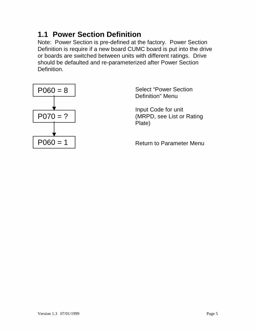
1.1 Power Section DefinitionNote: Power Section is pre-defined at the factory. Power SectionDefinition is require if a new board CUMC board is put into the driveor boards are switched between units with different ratings. Driveshould be defaulted and re-parameterized after Power SectionDefinition.
P060 = 8
P070 = ?
P060 = 1
Select “Power SectionDefinition” Menu
Input Code for unit(MRPD, see List or RatingPlate)
Return to Parameter Menu
Version 1.3 07/01/1999 Page 6
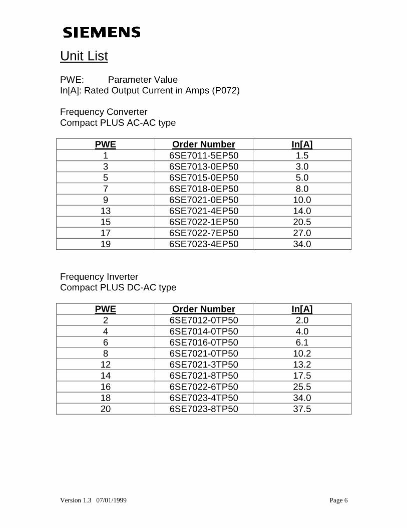
Unit List
PWE: Parameter ValueIn[A]: Rated Output Current in Amps (P072)
Frequency ConverterCompact PLUS AC-AC type
PWE Order Number In[A]1 6SE7011-5EP50 1.53 6SE7013-0EP50 3.05 6SE7015-0EP50 5.07 6SE7018-0EP50 8.09 6SE7021-0EP50 10.013 6SE7021-4EP50 14.015 6SE7022-1EP50 20.517 6SE7022-7EP50 27.019 6SE7023-4EP50 34.0
Frequency InverterCompact PLUS DC-AC type
PWE Order Number In[A]2 6SE7012-0TP50 2.04 6SE7014-0TP50 4.06 6SE7016-0TP50 6.18 6SE7021-0TP50 10.212 6SE7021-3TP50 13.214 6SE7021-8TP50 17.516 6SE7022-6TP50 25.518 6SE7023-4TP50 34.020 6SE7023-8TP50 37.5
Version 1.3 07/01/1999 Page 7
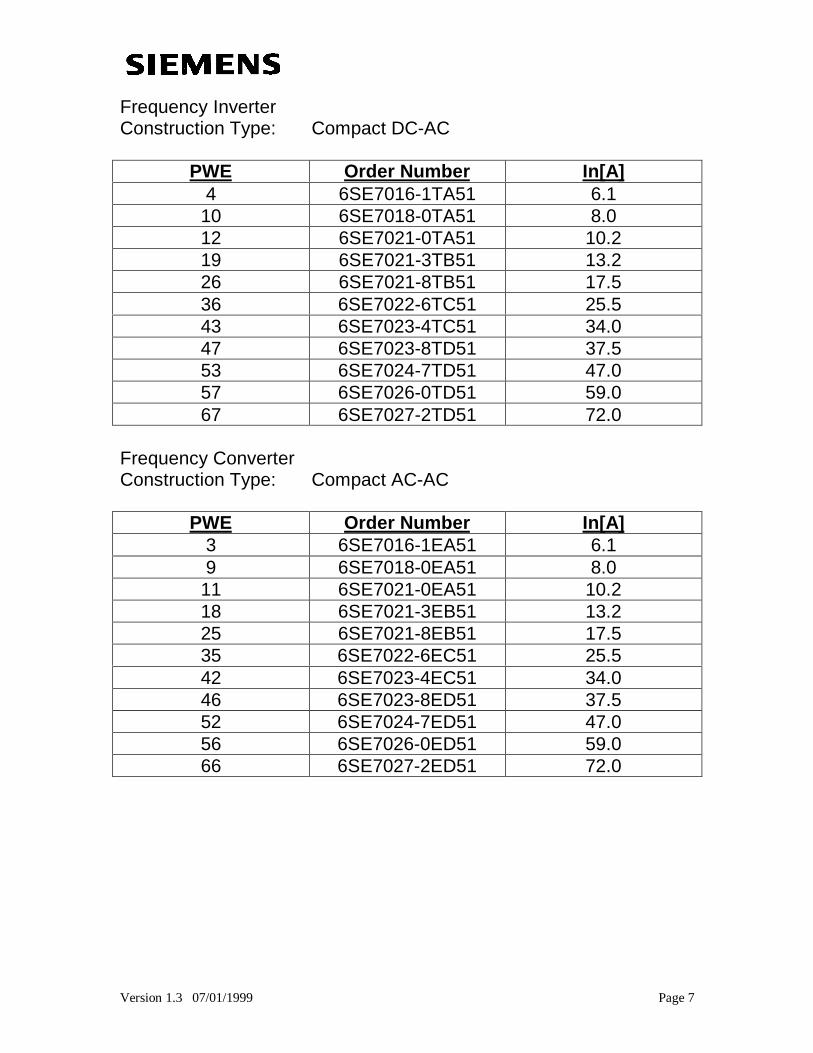
Frequency InverterConstruction Type: Compact DC-AC
PWE Order Number In[A]4 6SE7016-1TA51 6.110 6SE7018-0TA51 8.012 6SE7021-0TA51 10.219 6SE7021-3TB51 13.226 6SE7021-8TB51 17.536 6SE7022-6TC51 25.543 6SE7023-4TC51 34.047 6SE7023-8TD51 37.553 6SE7024-7TD51 47.057 6SE7026-0TD51 59.067 6SE7027-2TD51 72.0
Frequency ConverterConstruction Type: Compact AC-AC
PWE Order Number In[A]3 6SE7016-1EA51 6.19 6SE7018-0EA51 8.011 6SE7021-0EA51 10.218 6SE7021-3EB51 13.225 6SE7021-8EB51 17.535 6SE7022-6EC51 25.542 6SE7023-4EC51 34.046 6SE7023-8ED51 37.552 6SE7024-7ED51 47.056 6SE7026-0ED51 59.066 6SE7027-2ED51 72.0
Version 1.3 07/01/1999 Page 8
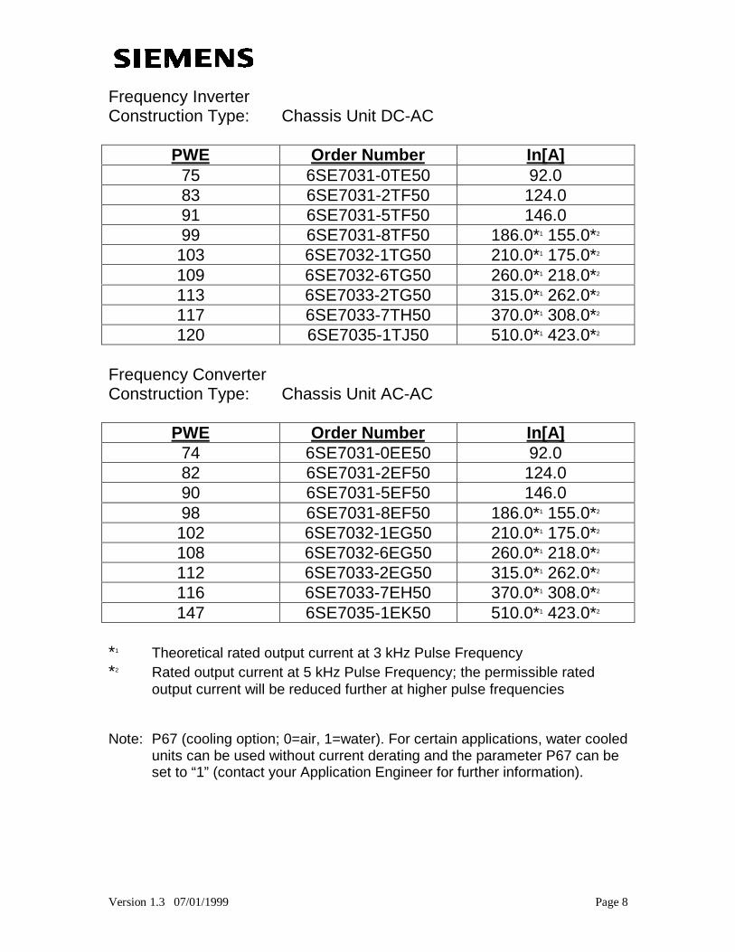
Frequency InverterConstruction Type: Chassis Unit DC-AC
PWE Order Number In[A]75 6SE7031-0TE50 92.083 6SE7031-2TF50 124.091 6SE7031-5TF50 146.099 6SE7031-8TF50 186.0*1 155.0*2
103 6SE7032-1TG50 210.0*1 175.0*2
109 6SE7032-6TG50 260.0*1 218.0*2
113 6SE7033-2TG50 315.0*1 262.0*2
117 6SE7033-7TH50 370.0*1 308.0*2
120 6SE7035-1TJ50 510.0*1 423.0*2
Frequency ConverterConstruction Type: Chassis Unit AC-AC
PWE Order Number In[A]74 6SE7031-0EE50 92.082 6SE7031-2EF50 124.090 6SE7031-5EF50 146.098 6SE7031-8EF50 186.0*1 155.0*2
102 6SE7032-1EG50 210.0*1 175.0*2
108 6SE7032-6EG50 260.0*1 218.0*2
112 6SE7033-2EG50 315.0*1 262.0*2
116 6SE7033-7EH50 370.0*1 308.0*2
147 6SE7035-1EK50 510.0*1 423.0*2
*1 Theoretical rated output current at 3 kHz Pulse Frequency*2 Rated output current at 5 kHz Pulse Frequency; the permissible rated
output current will be reduced further at higher pulse frequencies
Note: P67 (cooling option; 0=air, 1=water). For certain applications, water cooledunits can be used without current derating and the parameter P67 can beset to “1” (contact your Application Engineer for further information).
Version 1.3 07/01/1999 Page 9
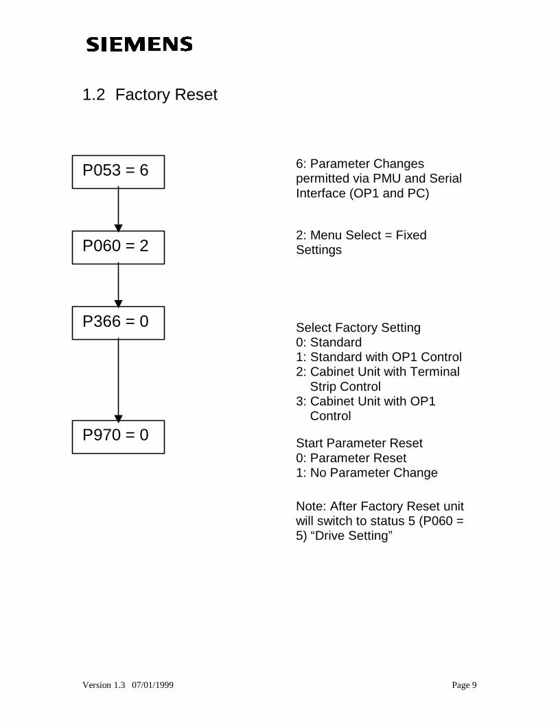
1.2 Factory Reset
P053 = 6
P060 = 2
P366 = 0
P970 = 0
6: Parameter Changespermitted via PMU and SerialInterface (OP1 and PC)
2: Menu Select = FixedSettings
Select Factory Setting0: Standard1: Standard with OP1 Control2: Cabinet Unit with Terminal Strip Control3: Cabinet Unit with OP1 Control
Start Parameter Reset0: Parameter Reset1: No Parameter Change
Note: After Factory Reset unitwill switch to status 5 (P060 =5) “Drive Setting”
Version 1.3 07/01/1999 Page 10
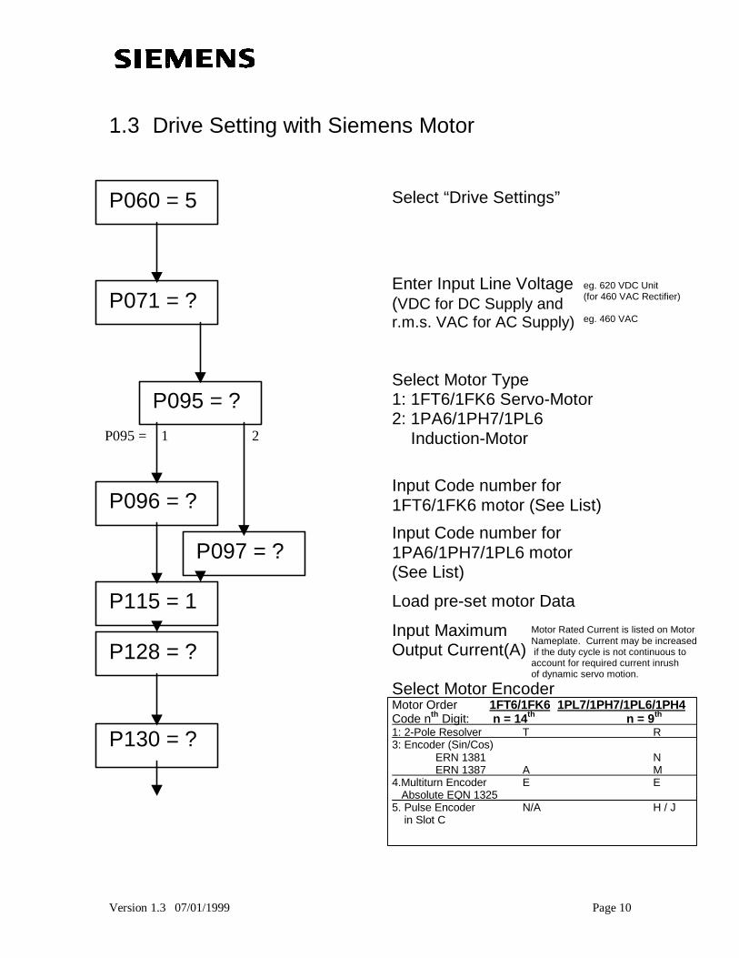
1.3 Drive Setting with Siemens Motor
P060 = 5
P071 = ?
P095 = ?
P096 = ?
P097 = ?
P115 = 1
P128 = ?
P130 = ?
Select “Drive Settings”
Enter Input Line Voltage(VDC for DC Supply andr.m.s. VAC for AC Supply)
Select Motor Type1: 1FT6/1FK6 Servo-Motor2: 1PA6/1PH7/1PL6 Induction-Motor
Input Code number for1FT6/1FK6 motor (See List)
Input Code number for1PA6/1PH7/1PL6 motor(See List)
Load pre-set motor Data
Input MaximumOutput Current(A)
Select Motor EncoderMotor Order 1FT6/1FK6 1PL7/1PH7/1PL6/1PH4Code nth Digit: n = 14th n = 9th
1: 2-Pole Resolver T R 3: Encoder (Sin/Cos)
ERN 1381 N ERN 1387 A M 4.Multiturn Encoder E E Absolute EQN 1325 5. Pulse Encoder N/A H / J in Slot C
P095 = 1 2
eg. 620 VDC Unit(for 460 VAC Rectifier)
eg. 460 VAC
Motor Rated Current is listed on MotorNameplate. Current may be increased if the duty cycle is not continuous toaccount for required current inrushof dynamic servo motion.
Version 1.3 07/01/1999 Page 11
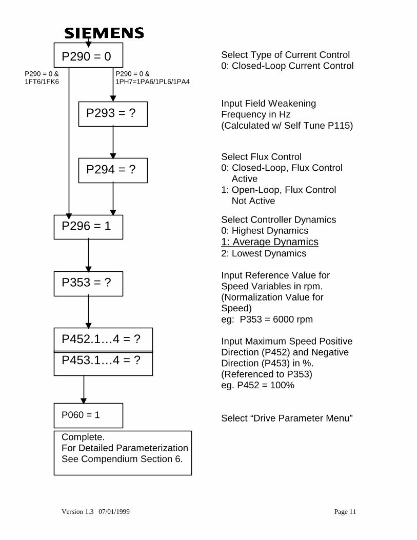
P290 = 0
P293 = ?
P294 = ?
P296 = 1
P353 = ?
P452.1… 4 = ?
P453.1… 4 = ?
P060 = 1
Complete.For Detailed ParameterizationSee Compendium Section 6.
Select Type of Current Control0: Closed-Loop Current Control
Input Field WeakeningFrequency in Hz(Calculated w/ Self Tune P115)
Select Flux Control0: Closed-Loop, Flux Control Active1: Open-Loop, Flux Control Not Active
Select Controller Dynamics0: Highest Dynamics1: Average Dynamics2: Lowest Dynamics
Input Reference Value forSpeed Variables in rpm.(Normalization Value forSpeed)eg: P353 = 6000 rpm
Input Maximum Speed PositiveDirection (P452) and NegativeDirection (P453) in %.(Referenced to P353)eg. P452 = 100%
Select “Drive Parameter Menu”
P290 = 0 & P290 = 0 &1FT6/1FK6 1PH7=1PA6/1PL6/1PA4
Version 1.3 07/01/1999 Page 12
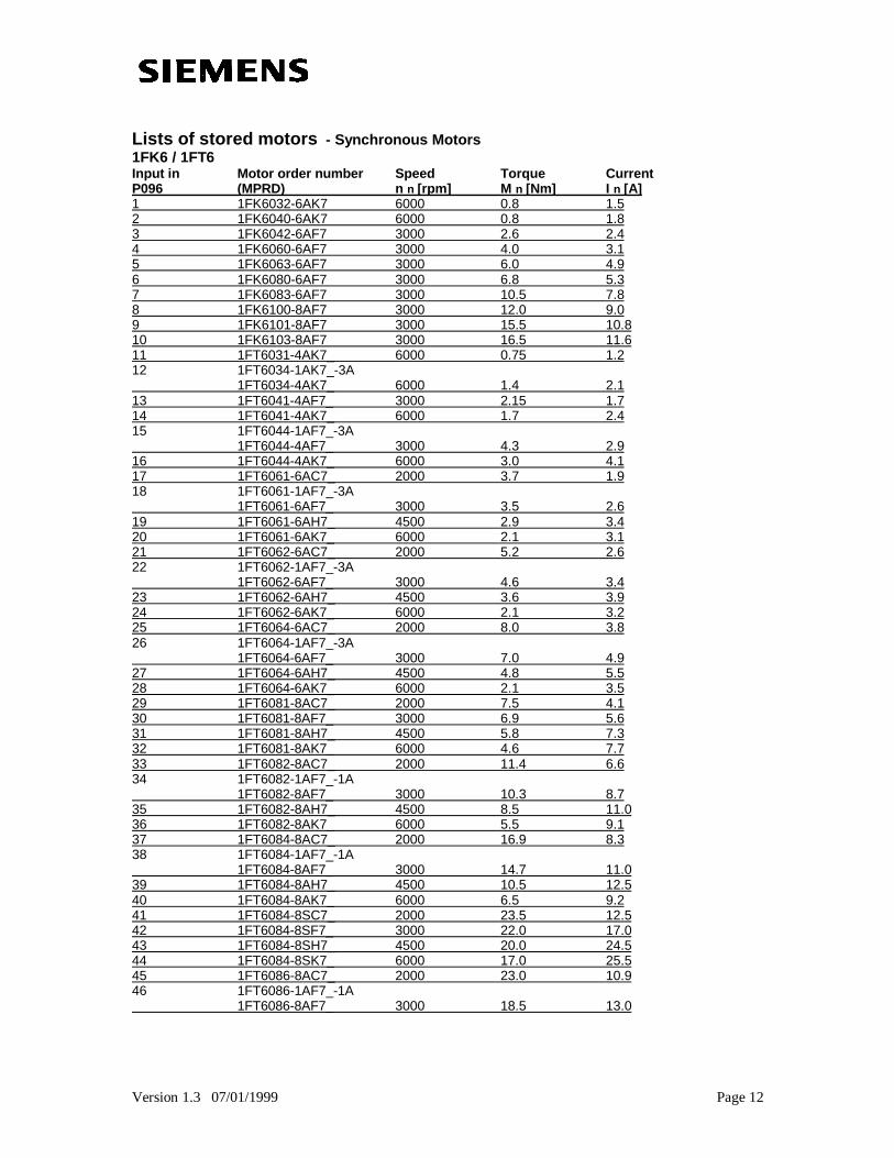
Lists of stored motors - Synchronous Motors1FK6 / 1FT6Input in Motor order number Speed Torque CurrentP096 (MPRD) n n [rpm] M n [Nm] I n [A]1 1FK6032-6AK7 6000 0.8 1.52 1FK6040-6AK7 6000 0.8 1.83 1FK6042-6AF7 3000 2.6 2.44 1FK6060-6AF7 3000 4.0 3.15 1FK6063-6AF7 3000 6.0 4.96 1FK6080-6AF7 3000 6.8 5.37 1FK6083-6AF7 3000 10.5 7.88 1FK6100-8AF7 3000 12.0 9.09 1FK6101-8AF7 3000 15.5 10.810 1FK6103-8AF7 3000 16.5 11.611 1FT6031-4AK7_ 6000 0.75 1.212 1FT6034-1AK7_-3A 1FT6034-4AK7_ 6000 1.4 2.113 1FT6041-4AF7_ 3000 2.15 1.714 1FT6041-4AK7_ 6000 1.7 2.415 1FT6044-1AF7_-3A 1FT6044-4AF7_ 3000 4.3 2.916 1FT6044-4AK7_ 6000 3.0 4.117 1FT6061-6AC7_ 2000 3.7 1.918 1FT6061-1AF7_-3A 1FT6061-6AF7_ 3000 3.5 2.619 1FT6061-6AH7_ 4500 2.9 3.420 1FT6061-6AK7_ 6000 2.1 3.121 1FT6062-6AC7_ 2000 5.2 2.622 1FT6062-1AF7_-3A 1FT6062-6AF7_ 3000 4.6 3.423 1FT6062-6AH7_ 4500 3.6 3.924 1FT6062-6AK7_ 6000 2.1 3.225 1FT6064-6AC7_ 2000 8.0 3.826 1FT6064-1AF7_-3A 1FT6064-6AF7_ 3000 7.0 4.927 1FT6064-6AH7_ 4500 4.8 5.528 1FT6064-6AK7_ 6000 2.1 3.529 1FT6081-8AC7_ 2000 7.5 4.130 1FT6081-8AF7_ 3000 6.9 5.631 1FT6081-8AH7_ 4500 5.8 7.332 1FT6081-8AK7_ 6000 4.6 7.733 1FT6082-8AC7_ 2000 11.4 6.634 1FT6082-1AF7_-1A 1FT6082-8AF7_ 3000 10.3 8.735 1FT6082-8AH7_ 4500 8.5 11.036 1FT6082-8AK7_ 6000 5.5 9.137 1FT6084-8AC7_ 2000 16.9 8.338 1FT6084-1AF7_-1A 1FT6084-8AF7_ 3000 14.7 11.039 1FT6084-8AH7_ 4500 10.5 12.540 1FT6084-8AK7_ 6000 6.5 9.241 1FT6084-8SC7_ 2000 23.5 12.542 1FT6084-8SF7_ 3000 22.0 17.043 1FT6084-8SH7_ 4500 20.0 24.544 1FT6084-8SK7_ 6000 17.0 25.545 1FT6086-8AC7_ 2000 23.0 10.946 1FT6086-1AF7_-1A 1FT6086-8AF7_ 3000 18.5 13.0
Version 1.3 07/01/1999 Page 13
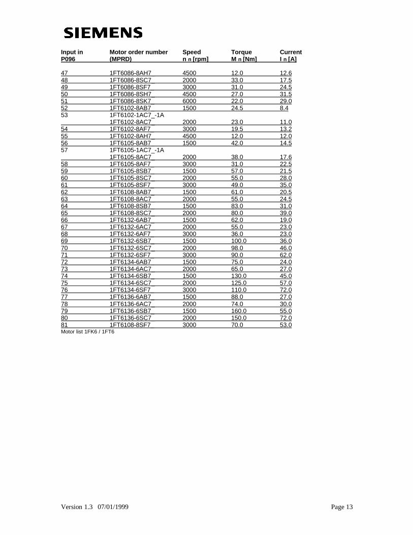
Input in Motor order number Speed Torque CurrentP096 (MPRD) n n [rpm] M n [Nm] I n [A]
47 1FT6086-8AH7_ 4500 12.0 12.648 1FT6086-8SC7_ 2000 33.0 17.549 1FT6086-8SF7_ 3000 31.0 24.550 1FT6086-8SH7_ 4500 27.0 31.551 1FT6086-8SK7_ 6000 22.0 29.052 1FT6102-8AB7_ 1500 24.5 8.453 1FT6102-1AC7_-1A 1FT6102-8AC7_ 2000 23.0 11.054 1FT6102-8AF7_ 3000 19.5 13.255 1FT6102-8AH7_ 4500 12.0 12.056 1FT6105-8AB7_ 1500 42.0 14.557 1FT6105-1AC7_-1A 1FT6105-8AC7_ 2000 38.0 17.658 1FT6105-8AF7_ 3000 31.0 22.559 1FT6105-8SB7_ 1500 57.0 21.560 1FT6105-8SC7_ 2000 55.0 28.061 1FT6105-8SF7_ 3000 49.0 35.062 1FT6108-8AB7_ 1500 61.0 20.563 1FT6108-8AC7_ 2000 55.0 24.564 1FT6108-8SB7_ 1500 83.0 31.065 1FT6108-8SC7_ 2000 80.0 39.066 1FT6132-6AB7_ 1500 62.0 19.067 1FT6132-6AC7_ 2000 55.0 23.068 1FT6132-6AF7_ 3000 36.0 23.069 1FT6132-6SB7_ 1500 100.0 36.070 1FT6132-6SC7_ 2000 98.0 46.071 1FT6132-6SF7_ 3000 90.0 62.072 1FT6134-6AB7_ 1500 75.0 24.073 1FT6134-6AC7_ 2000 65.0 27.074 1FT6134-6SB7_ 1500 130.0 45.075 1FT6134-6SC7_ 2000 125.0 57.076 1FT6134-6SF7_ 3000 110.0 72.077 1FT6136-6AB7_ 1500 88.0 27.078 1FT6136-6AC7_ 2000 74.0 30.079 1FT6136-6SB7_ 1500 160.0 55.080 1FT6136-6SC7_ 2000 150.0 72.081 1FT6108-8SF7_ 3000 70.0 53.0Motor list 1FK6 / 1FT6
Version 1.3 07/01/1999 Page 14
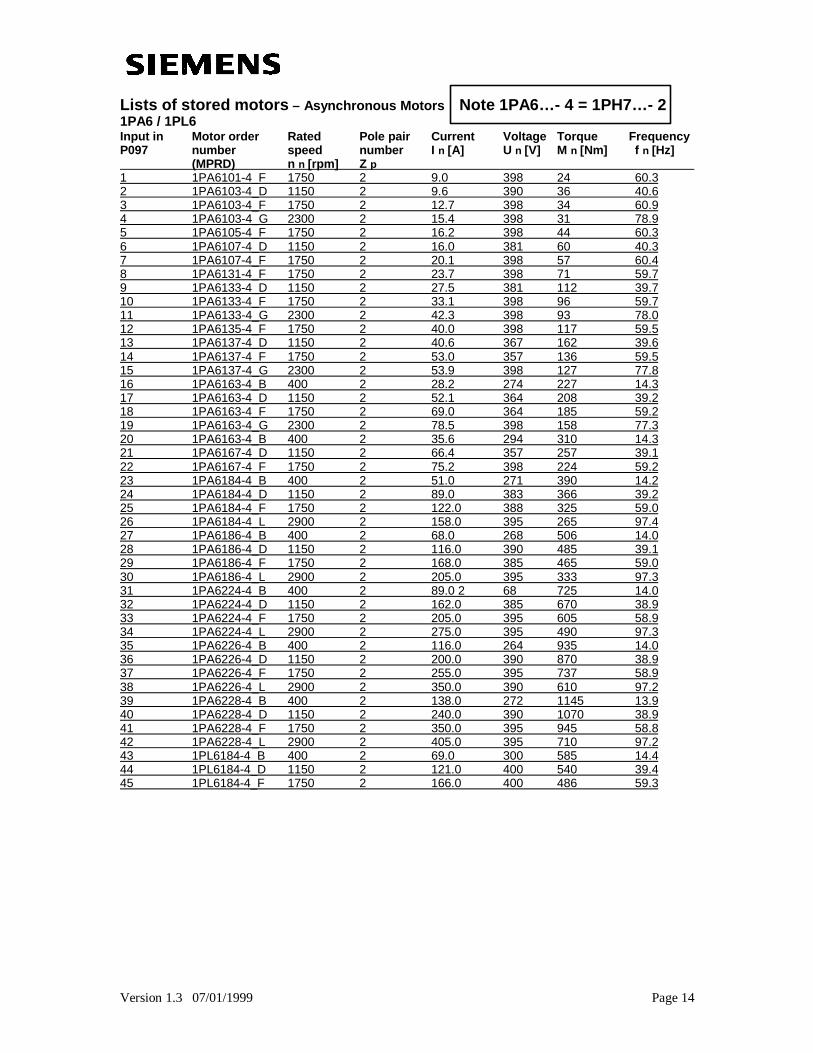
Lists of stored motors – Asynchronous Motors Note 1PA6… - 4 = 1PH7… - 21PA6 / 1PL6Input in Motor order Rated Pole pair Current Voltage Torque FrequencyP097 number speed number I n [A] U n [V] M n [Nm] f n [Hz] (MPRD) n n [rpm] Z p 1 1PA6101-4_F 1750 2 9.0 398 24 60.32 1PA6103-4_D 1150 2 9.6 390 36 40.63 1PA6103-4_F 1750 2 12.7 398 34 60.94 1PA6103-4_G 2300 2 15.4 398 31 78.95 1PA6105-4_F 1750 2 16.2 398 44 60.36 1PA6107-4_D 1150 2 16.0 381 60 40.37 1PA6107-4_F 1750 2 20.1 398 57 60.48 1PA6131-4_F 1750 2 23.7 398 71 59.79 1PA6133-4_D 1150 2 27.5 381 112 39.710 1PA6133-4_F 1750 2 33.1 398 96 59.711 1PA6133-4_G 2300 2 42.3 398 93 78.012 1PA6135-4_F 1750 2 40.0 398 117 59.513 1PA6137-4_D 1150 2 40.6 367 162 39.614 1PA6137-4_F 1750 2 53.0 357 136 59.515 1PA6137-4_G 2300 2 53.9 398 127 77.816 1PA6163-4_B 400 2 28.2 274 227 14.317 1PA6163-4_D 1150 2 52.1 364 208 39.218 1PA6163-4_F 1750 2 69.0 364 185 59.219 1PA6163-4_G 2300 2 78.5 398 158 77.320 1PA6163-4_B 400 2 35.6 294 310 14.321 1PA6167-4_D 1150 2 66.4 357 257 39.122 1PA6167-4_F 1750 2 75.2 398 224 59.223 1PA6184-4_B 400 2 51.0 271 390 14.224 1PA6184-4_D 1150 2 89.0 383 366 39.225 1PA6184-4_F 1750 2 122.0 388 325 59.026 1PA6184-4_L 2900 2 158.0 395 265 97.427 1PA6186-4_B 400 2 68.0 268 506 14.028 1PA6186-4_D 1150 2 116.0 390 485 39.129 1PA6186-4_F 1750 2 168.0 385 465 59.030 1PA6186-4_L 2900 2 205.0 395 333 97.331 1PA6224-4_B 400 2 89.0 2 68 725 14.032 1PA6224-4_D 1150 2 162.0 385 670 38.933 1PA6224-4_F 1750 2 205.0 395 605 58.934 1PA6224-4_L 2900 2 275.0 395 490 97.335 1PA6226-4_B 400 2 116.0 264 935 14.036 1PA6226-4_D 1150 2 200.0 390 870 38.937 1PA6226-4_F 1750 2 255.0 395 737 58.938 1PA6226-4_L 2900 2 350.0 390 610 97.239 1PA6228-4_B 400 2 138.0 272 1145 13.940 1PA6228-4_D 1150 2 240.0 390 1070 38.941 1PA6228-4_F 1750 2 350.0 395 945 58.842 1PA6228-4_L 2900 2 405.0 395 710 97.243 1PL6184-4_B 400 2 69.0 300 585 14.444 1PL6184-4_D 1150 2 121.0 400 540 39.445 1PL6184-4_F 1750 2 166.0 400 486 59.3
Version 1.3 07/01/1999 Page 15
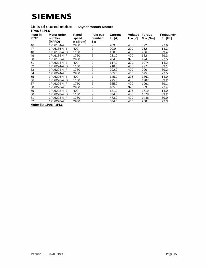
Lists of stored motors – Asynchronous Motors1PA6 / 1PL6Input in Motor order Rated Pole pair Current Voltage Torque FrequencyP097 number speed number I n [A] U n [V] M n [Nm] f n [Hz] (MPRD) n n [rpm] Z p 46 1PL6184-4_L 2900 2 209.0 400 372 97.647 1PL6186-4_B 400 2 90.0 290 752 14.348 1PL6186-4_D 1150 2 158.0 400 706 39.449 1PL6186-4_F 1750 2 231.0 400 682 59.350 1PL6186-4_L 2900 2 284.0 390 494 97.551 1PL6224-4_B 400 2 117.0 300 1074 14.252 1PL6224-4_D 1150 2 218.0 400 997 39.153 1PL6224-4_F 1750 2 292.0 400 900 59.254 1PL6224-4_L 2900 2 365.0 400 675 97.555 1PL6226-4_B 400 2 145.0 305 1361 14.056 1PL6226-4_D 1150 2 275.0 400 1287 39.257 1PL6226-4_F 1750 2 355.0 400 1091 59.158 1PL6226-4_L 2900 2 485.0 395 889 97.459 1PL6228-4_B 400 2 181.0 305 1719 14.060 1PL6228-4_D 1150 2 334.0 400 1578 39.261 1PL6228-4_F 1750 2 473.0 400 1448 59.062 1PL6228-4_L 2900 2 534.0 400 988 97.3Motor list 1PA6 / 1PL6
Version 1.3 07/01/1999 Page 16
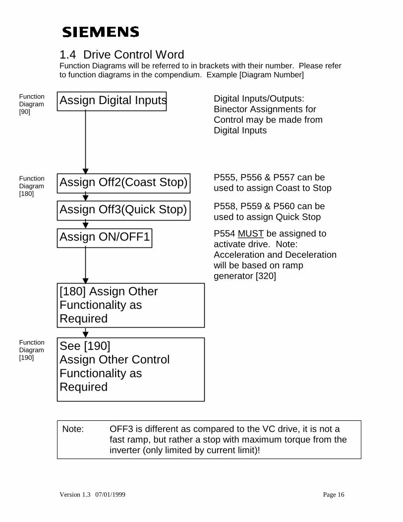
1.4 Drive Control WordFunction Diagrams will be referred to in brackets with their number. Please referto function diagrams in the compendium. Example [Diagram Number]
Assign Digital Inputs
Assign Off2(Coast Stop)
Assign Off3(Quick Stop)
Assign ON/OFF1
[180] Assign OtherFunctionality asRequired
See [190]Assign Other ControlFunctionality asRequired
Digital Inputs/Outputs:Binector Assignments forControl may be made fromDigital Inputs
P555, P556 & P557 can beused to assign Coast to Stop
P558, P559 & P560 can beused to assign Quick Stop
P554 MUST be assigned toactivate drive. Note:Acceleration and Decelerationwill be based on rampgenerator [320]
FunctionDiagram[180]
FunctionDiagram[90]
FunctionDiagram[190]
Note: OFF3 is different as compared to the VC drive, it is not afast ramp, but rather a stop with maximum torque from theinverter (only limited by current limit)!
Version 1.3 07/01/1999 Page 17
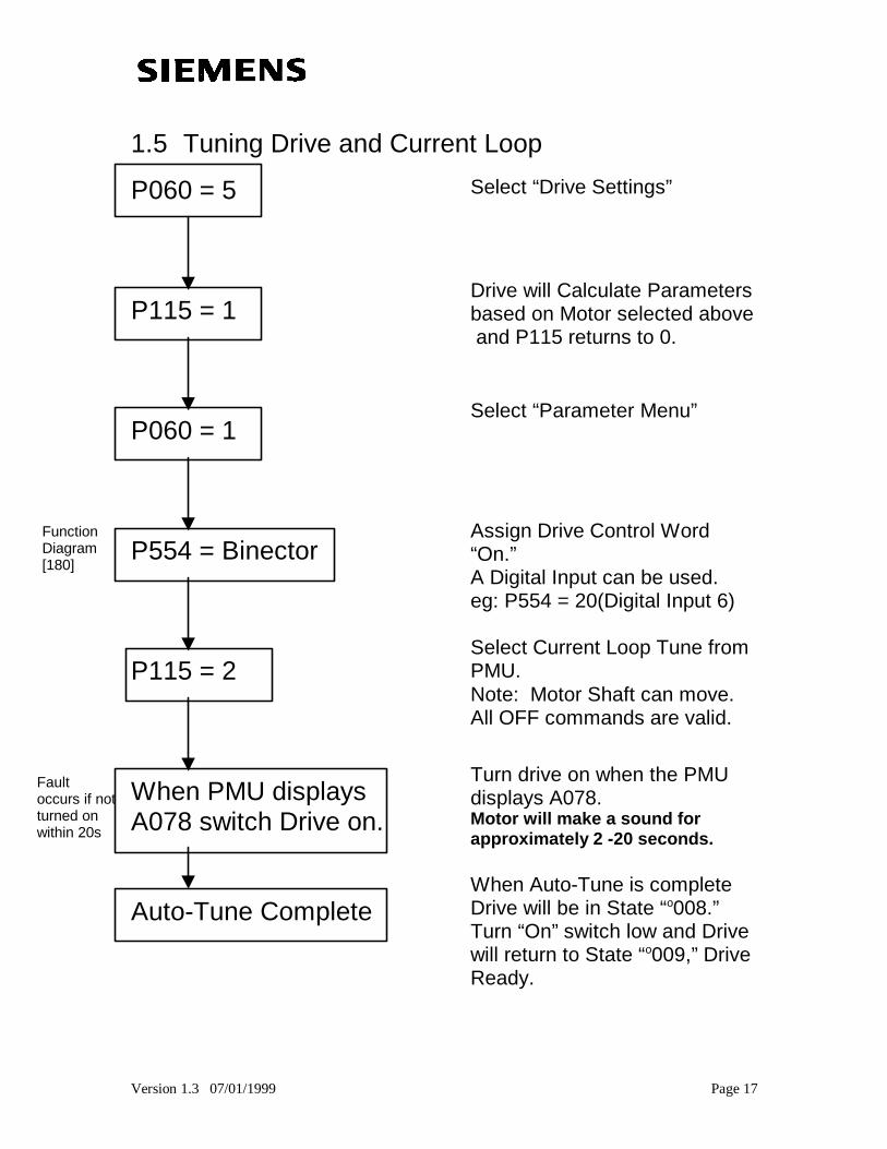
1.5 Tuning Drive and Current Loop
P060 = 5
P115 = 1
P060 = 1
P554 = Binector
P115 = 2
When PMU displaysA078 switch Drive on.
Auto-Tune Complete
Select “Drive Settings”
Drive will Calculate Parametersbased on Motor selected above and P115 returns to 0.
Select “Parameter Menu”
Assign Drive Control Word“On.”A Digital Input can be used.eg: P554 = 20(Digital Input 6)
Select Current Loop Tune fromPMU.Note: Motor Shaft can move.All OFF commands are valid.
Turn drive on when the PMUdisplays A078.Motor will make a sound forapproximately 2 -20 seconds.
When Auto-Tune is completeDrive will be in State “o008.”Turn “On” switch low and Drivewill return to State “o009,” DriveReady.
FunctionDiagram[180]
Faultoccurs if notturned onwithin 20s
Version 1.3 07/01/1999 Page 18
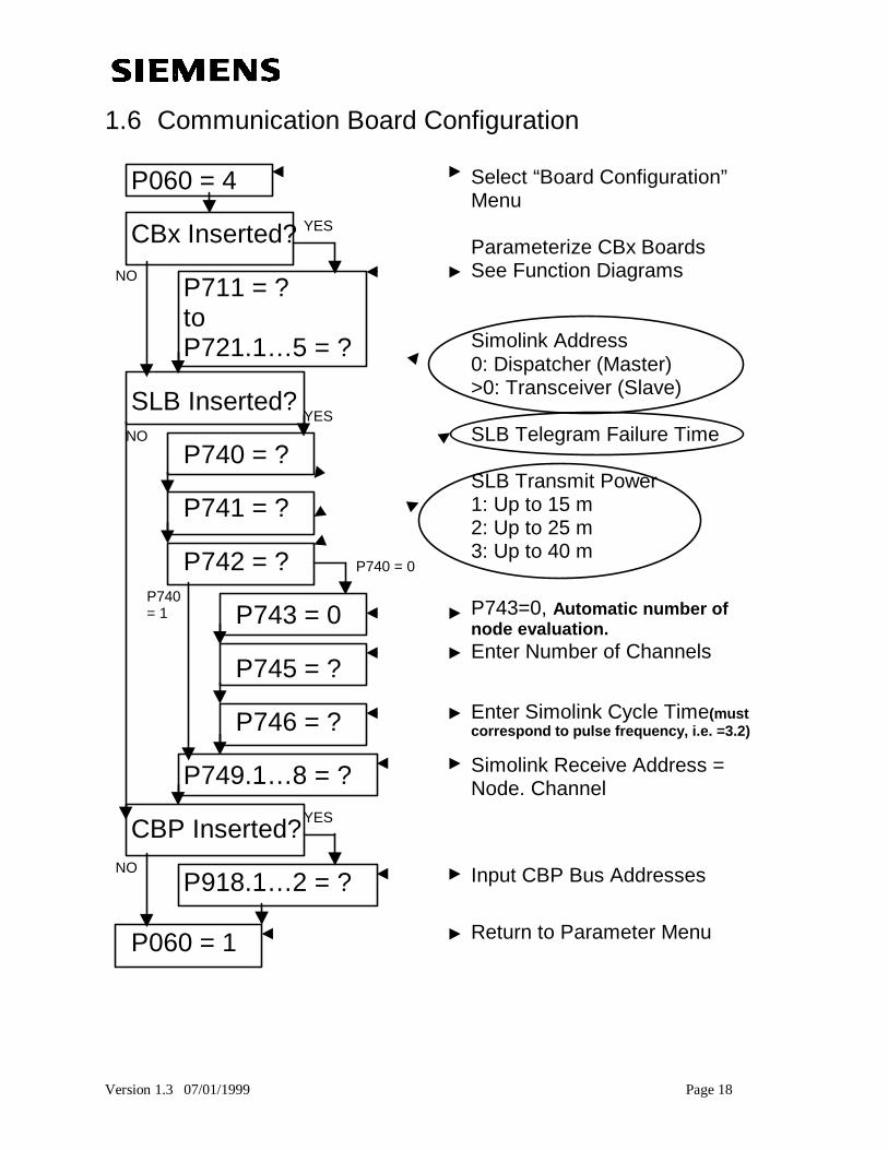
1.6 Communication Board Configuration
P060 = 4
CBx Inserted?
P711 = ?toP721.1… 5 = ?
SLB Inserted?
P740 = ?
P741 = ?
P742 = ?
P743 = 0
P745 = ?
P746 = ?
P749.1… 8 = ?
CBP Inserted?
P918.1… 2 = ?
P060 = 1
Select “Board Configuration”Menu
Parameterize CBx BoardsSee Function Diagrams
Simolink Address0: Dispatcher (Master)>0: Transceiver (Slave)
SLB Telegram Failure Time
SLB Transmit Power1: Up to 15 m2: Up to 25 m3: Up to 40 m
P743=0, Automatic number ofnode evaluation.Enter Number of Channels
Enter Simolink Cycle Time(mustcorrespond to pulse frequency, i.e. =3.2)
Simolink Receive Address =Node. Channel
Input CBP Bus Addresses
Return to Parameter Menu
YES
NO
YES
YES
NO
NO
P740 = 0
P740= 1
Version 1.3 07/01/1999 Page 19
Section 2:Servo Drive Tuning Procedure
SIMOVERT MASTERDRIVES6SE70 MC
Motion Control
Version 1.3 07/01/1999 Page 20
Servo Drive Tuning ProcedureSection 2 Table of Contents:
2.1 Drive Tuning Considerations and Overview
2.2 Configuring Drive
2.3 Configuring Drive For Speed Controller Tuning
2.4 Set Speed Controller Proportional Gain (Kp)
2.5 Set Speed Controller Integral Gain (Tn)
2.6 Set Position Controller Proportional Gain
Version 1.3 07/01/1999 Page 21
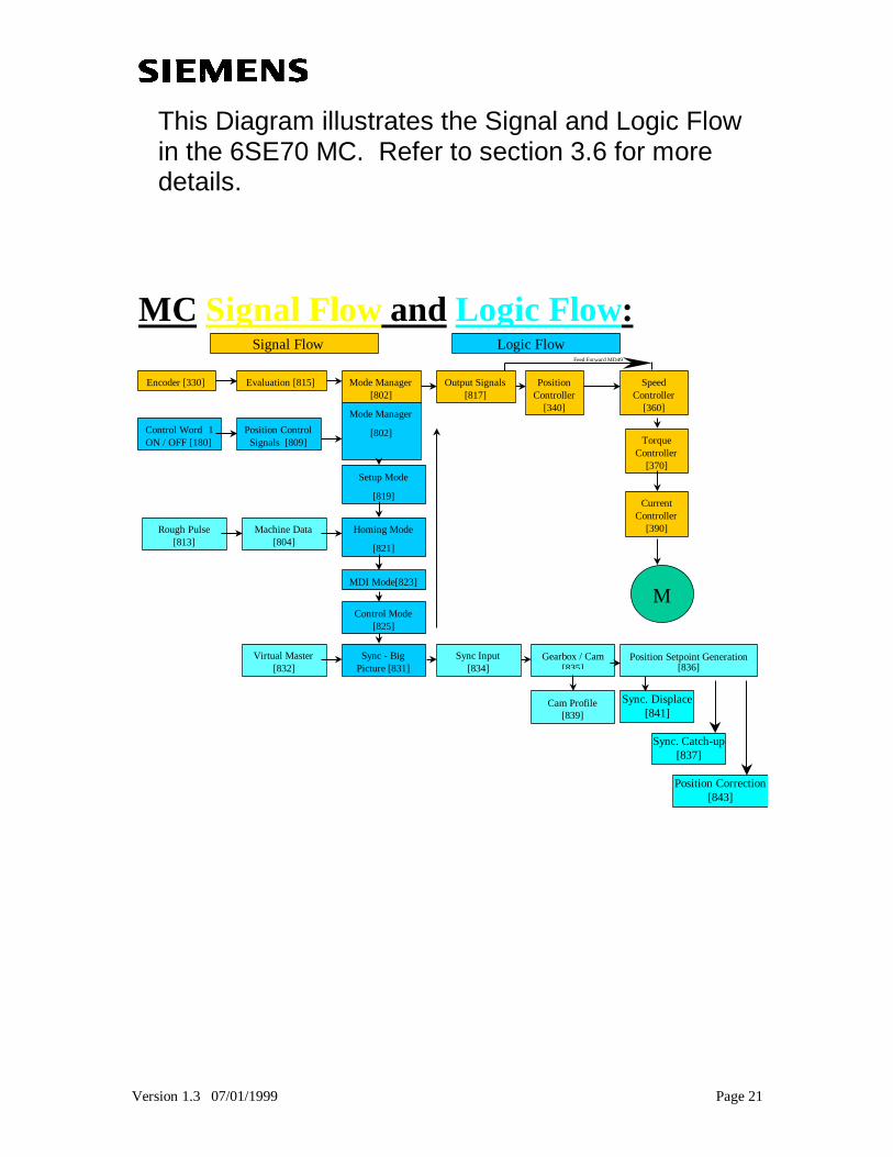
This Diagram illustrates the Signal and Logic Flowin the 6SE70 MC. Refer to section 3.6 for moredetails.
MC Signal Flow and Logic Flow :
Encoder [330] Evaluation [815] Mode Manager[802]
Output Signals[817]
PositionController
[340]
SpeedController
[360]
TorqueController
[370]
CurrentController
[390]
M
Control Word 1ON / OFF [180]
Position ControlSignals [809]
Setup Mode
[819]
Homing Mode
[821]
MDI Mode[823]
Rough Pulse[813]
Machine Data[804]
Control Mode[825]
Sync - BigPicture [831]
Virtual Master[832]
Sync Input[834]
Cam Profile[839]
Mode Manager
[802]
Signal Flow Logic Flow
Position Setpoint Generation[836]
Gearbox / Cam[835]
Sync. Displace[841]
Sync. Catch-up[837]
Position Correction[843]
Feed Forward MD49
Version 1.3 07/01/1999 Page 22
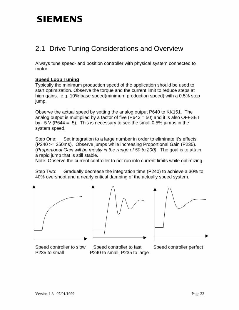
2.1 Drive Tuning Considerations and Overview
Always tune speed- and position controller with physical system connected tomotor.
Speed Loop TuningTypically the minimum production speed of the application should be used tostart optimization. Observe the torque and the current limit to reduce steps athigh gains. e.g. 10% base speed(minimum production speed) with a 0.5% stepjump.
Observe the actual speed by setting the analog output P640 to KK151. Theanalog output is multiplied by a factor of five (P643 = 50) and it is also OFFSETby –5 V (P644 = -5). This is necessary to see the small 0.5% jumps in thesystem speed.
Step One: Set integration to a large number in order to eliminate it’s effects(P240 >= 250ms). Observe jumps while increasing Proportional Gain (P235).(Proportional Gain will be mostly in the range of 50 to 200). The goal is to attaina rapid jump that is still stable.Note: Observe the current controller to not run into current limits while optimizing.
Step Two: Gradually decrease the integration time (P240) to achieve a 30% to40% overshoot and a nearly critical damping of the actually speed system.
Speed controller to slow Speed controller to fast Speed controller perfectP235 to small P240 to small, P235 to large
Version 1.3 07/01/1999 Page 23
Notes:
While tuning the speed controller, make sure the torque step does not reach thelimits of torque or current (a step of 0.5% causes a 100% torque step when gainis 200). For high gains the step should be smaller e.g. 0.1%. Check controllersetting at minimum speed and maximum speed and watch behavior during rampup, ramp down and fast stop.
Set the integral part of speed controller (P240 [360]) to maximum(1000) toeliminate the influence of it. Increase the proportional gain for fast responsewithout overshoot. Increase smoothing if necessary to increase proportionalgain. Reduce the step if the proportional gain is higher than 100 ( step * gain =torque-step).
Decrease the integral part to reach a 43% overshoot in step response. Thetheoretical value is Tn = 4 * (2ms + Tgl); Tgl is the smoothing time of the actualspeed value ( if no smoothing is used Tn can be 7 to 8 ms).
In multi-drive applications the smoothing factor must be equal for all the driveswhich have to perform together in order to get the same response from everydrive. Also, the smoothing of the setpoint must be the same as the smoothing ofthe actual value.
If no smoothing of the actual value is used( P223 = 0), then the smoothing factorof the speed controller setpoint should be 0.5ms to 0.8ms. Because of differentcalculation cycles between the position controller and the speed controller,setpoint smoothing is required to produce a smoother torque setpoint.
Version 1.3 07/01/1999 Page 24
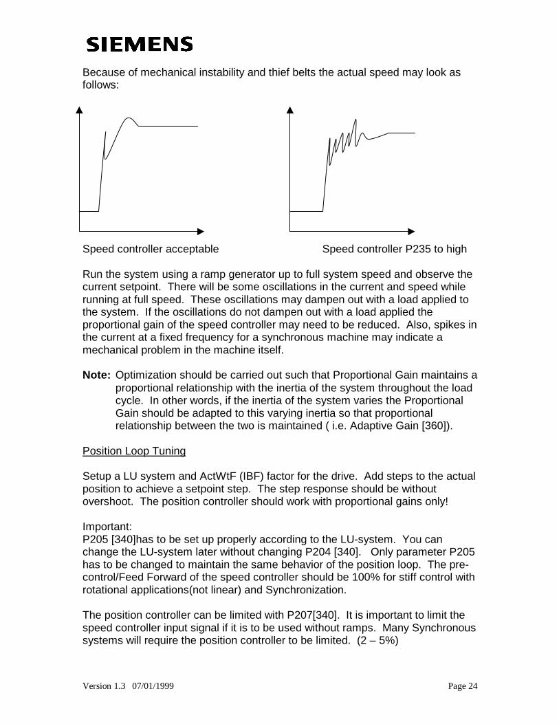
Because of mechanical instability and thief belts the actual speed may look asfollows:
Speed controller acceptable Speed controller P235 to high
Run the system using a ramp generator up to full system speed and observe thecurrent setpoint. There will be some oscillations in the current and speed whilerunning at full speed. These oscillations may dampen out with a load applied tothe system. If the oscillations do not dampen out with a load applied theproportional gain of the speed controller may need to be reduced. Also, spikes inthe current at a fixed frequency for a synchronous machine may indicate amechanical problem in the machine itself.
Note: Optimization should be carried out such that Proportional Gain maintains aproportional relationship with the inertia of the system throughout the loadcycle. In other words, if the inertia of the system varies the ProportionalGain should be adapted to this varying inertia so that proportionalrelationship between the two is maintained ( i.e. Adaptive Gain [360]).
Position Loop Tuning
Setup a LU system and ActWtF (IBF) factor for the drive. Add steps to the actualposition to achieve a setpoint step. The step response should be withoutovershoot. The position controller should work with proportional gains only!
Important:P205 [340]has to be set up properly according to the LU-system. You canchange the LU-system later without changing P204 [340]. Only parameter P205has to be changed to maintain the same behavior of the position loop. The pre-control/Feed Forward of the speed controller should be 100% for stiff control withrotational applications(not linear) and Synchronization.
The position controller can be limited with P207[340]. It is important to limit thespeed controller input signal if it is to be used without ramps. Many Synchronoussystems will require the position controller to be limited. (2 – 5%)
Version 1.3 07/01/1999 Page 25
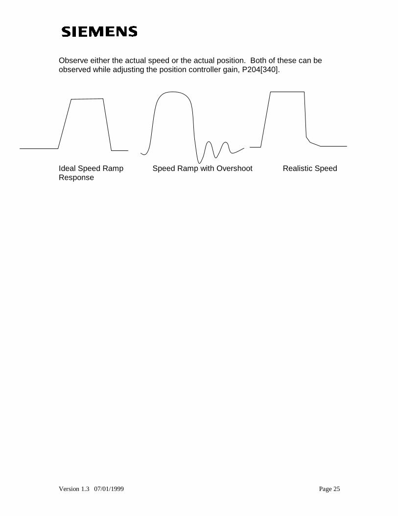
Observe either the actual speed or the actual position. Both of these can beobserved while adjusting the position controller gain, P204[340].
Ideal Speed Ramp Speed Ramp with Overshoot Realistic SpeedResponse
Version 1.3 07/01/1999 Page 26
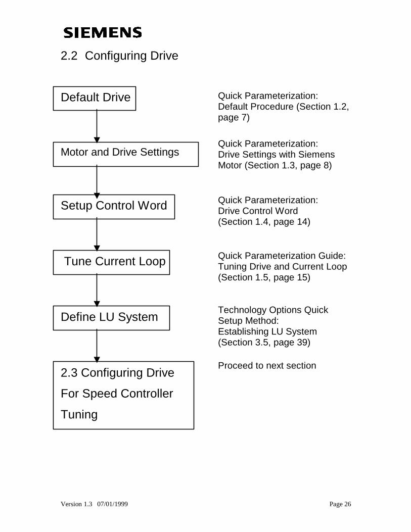
2.2 Configuring Drive
Default Drive
Motor and Drive Settings
Setup Control Word
Tune Current Loop
Define LU System
2.3 Configuring Drive
For Speed Controller
Tuning
Quick Parameterization:Default Procedure (Section 1.2,page 7)
Quick Parameterization:Drive Settings with SiemensMotor (Section 1.3, page 8)
Quick Parameterization:Drive Control Word(Section 1.4, page 14)
Quick Parameterization Guide:Tuning Drive and Current Loop(Section 1.5, page 15)
Technology Options QuickSetup Method:Establishing LU System(Section 3.5, page 39)
Proceed to next section
Version 1.3 07/01/1999 Page 27
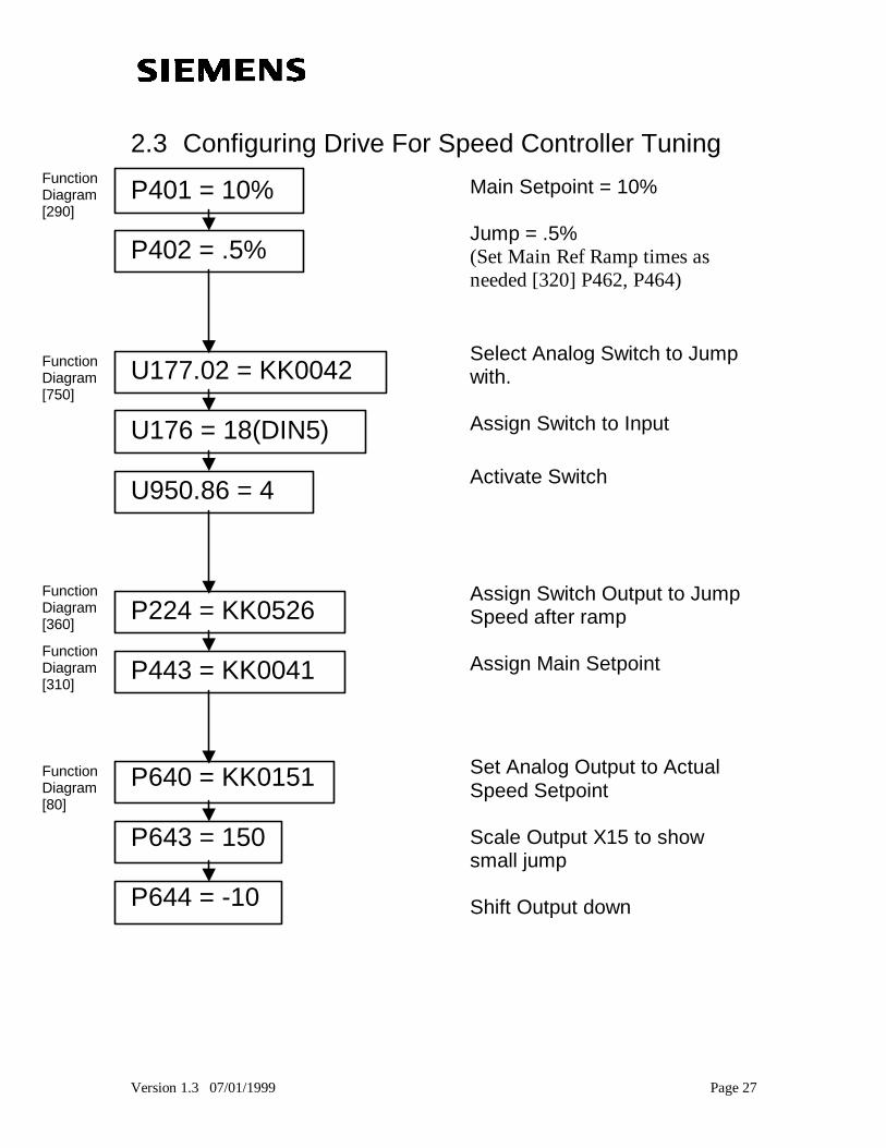
2.3 Configuring Drive For Speed Controller Tuning
P401 = 10%
P402 = .5%
U177.02 = KK0042
U176 = 18(DIN5)
U950.86 = 4
P224 = KK0526
P443 = KK0041
P640 = KK0151
P643 = 150
P644 = -10
Main Setpoint = 10%
Jump = .5%(Set Main Ref Ramp times asneeded [320] P462, P464)
Select Analog Switch to Jumpwith.
Assign Switch to Input
Activate Switch
Assign Switch Output to JumpSpeed after ramp
Assign Main Setpoint
Set Analog Output to ActualSpeed Setpoint
Scale Output X15 to showsmall jump
Shift Output down
FunctionDiagram[290]
FunctionDiagram[750]
FunctionDiagram[360]
FunctionDiagram[310]
FunctionDiagram[80]
Version 1.3 07/01/1999 Page 28
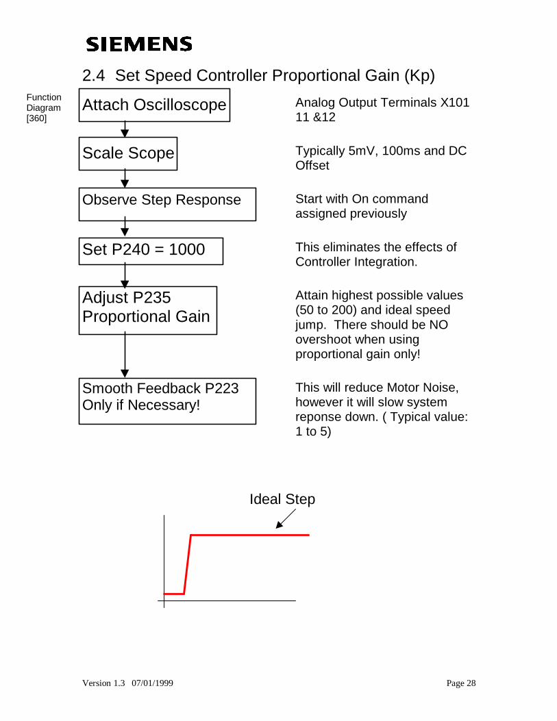
2.4 Set Speed Controller Proportional Gain (Kp)
Attach Oscilloscope Analog Output Terminals X10111 &12
Scale Scope Typically 5mV, 100ms and DCOffset
Observe Step Response Start with On commandassigned previously
Set P240 = 1000 This eliminates the effects ofController Integration.
Adjust P235Proportional Gain
Attain highest possible values(50 to 200) and ideal speedjump. There should be NOovershoot when usingproportional gain only!
Smooth Feedback P223Only if Necessary!
This will reduce Motor Noise,however it will slow systemreponse down. ( Typical value:1 to 5)
Ideal StepResponse
FunctionDiagram[360]
Version 1.3 07/01/1999 Page 29
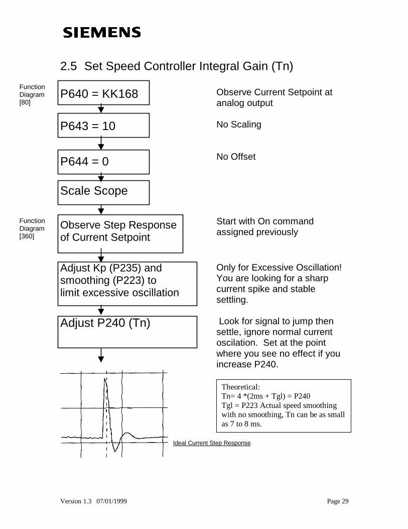
2.5 Set Speed Controller Integral Gain (Tn)
P640 = KK168 Observe Current Setpoint atanalog output
P643 = 10 No Scaling
P644 = 0 No Offset
Scale Scope
Observe Step Responseof Current Setpoint
Start with On commandassigned previously
Adjust Kp (P235) andsmoothing (P223) tolimit excessive oscillation
Only for Excessive Oscillation!You are looking for a sharpcurrent spike and stablesettling.
Adjust P240 (Tn) Look for signal to jump thensettle, ignore normal currentoscilation. Set at the pointwhere you see no effect if youincrease P240.
FunctionDiagram[80]
FunctionDiagram[360]
Ideal Current Step Response
Theoretical:Tn= 4 *(2ms + Tgl) = P240Tgl = P223 Actual speed smoothingwith no smoothing, Tn can be as smallas 7 to 8 ms.
Version 1.3 07/01/1999 Page 30
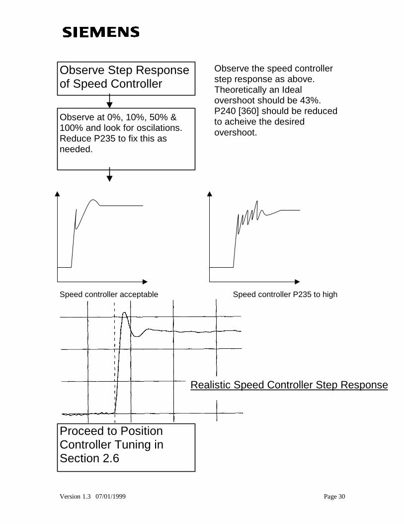
Observe Step Responseof Speed Controller
Observe at 0%, 10%, 50% &100% and look for oscilations.Reduce P235 to fix this asneeded.
Observe the speed controllerstep response as above.Theoretically an Idealovershoot should be 43%.P240 [360] should be reducedto acheive the desiredovershoot.
Speed controller acceptable Speed controller P235 to high
Proceed to PositionController Tuning inSection 2.6
Realistic Speed Controller Step Response
Version 1.3 07/01/1999 Page 31
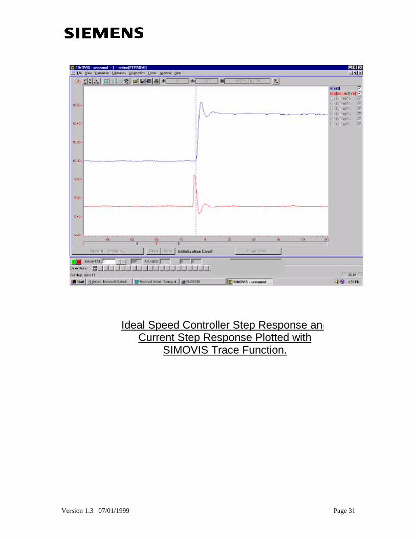
Ideal Speed Controller Step Response andCurrent Step Response Plotted with
SIMOVIS Trace Function.
Version 1.3 07/01/1999 Page 32
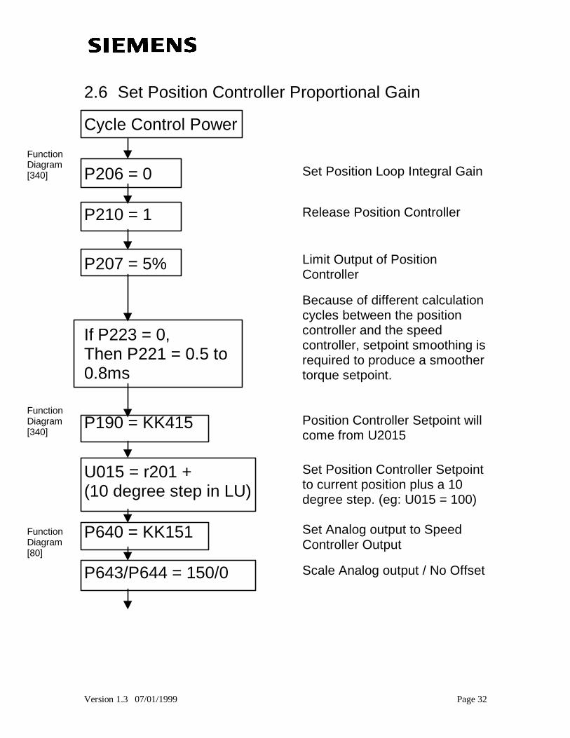
2.6 Set Position Controller Proportional Gain
Cycle Control Power
P206 = 0 Set Position Loop Integral Gain
P210 = 1 Release Position Controller
P207 = 5%
If P223 = 0,Then P221 = 0.5 to0.8ms
Limit Output of PositionController
Because of different calculationcycles between the positioncontroller and the speedcontroller, setpoint smoothing isrequired to produce a smoothertorque setpoint.
P190 = KK415 Position Controller Setpoint willcome from U2015
U015 = r201 +(10 degree step in LU)
Set Position Controller Setpointto current position plus a 10degree step. (eg: U015 = 100)
P640 = KK151 Set Analog output to SpeedController Output
P643/P644 = 150/0 Scale Analog output / No Offset
FunctionDiagram[340]
FunctionDiagram[340]
FunctionDiagram[80]
Version 1.3 07/01/1999 Page 33
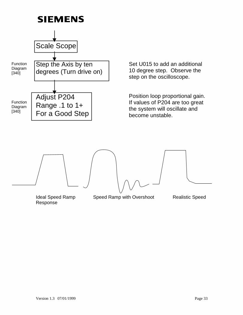
Scale Scope
Step the Axis by tendegrees (Turn drive on)
Set U015 to add an additional10 degree step. Observe thestep on the oscilloscope.
Adjust P204Range .1 to 1+For a Good Step
Position loop proportional gain.If values of P204 are too greatthe system will oscillate andbecome unstable.
Ideal Speed Ramp Speed Ramp with Overshoot Realistic SpeedResponse
FunctionDiagram[340]
FunctionDiagram[340]
Version 1.3 07/01/1999 Page 34
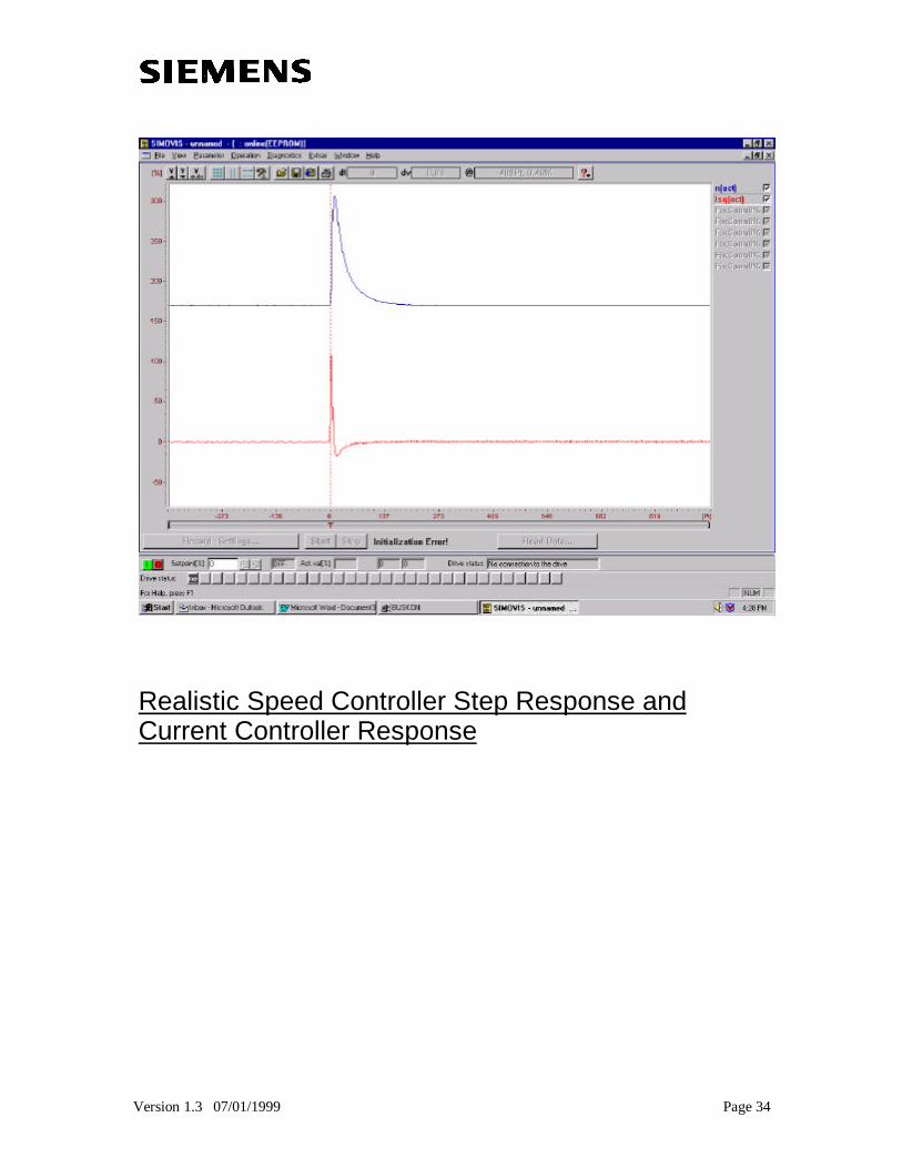
Realistic Speed Controller Step Response andCurrent Controller Response
Version 1.3 07/01/1999 Page 35
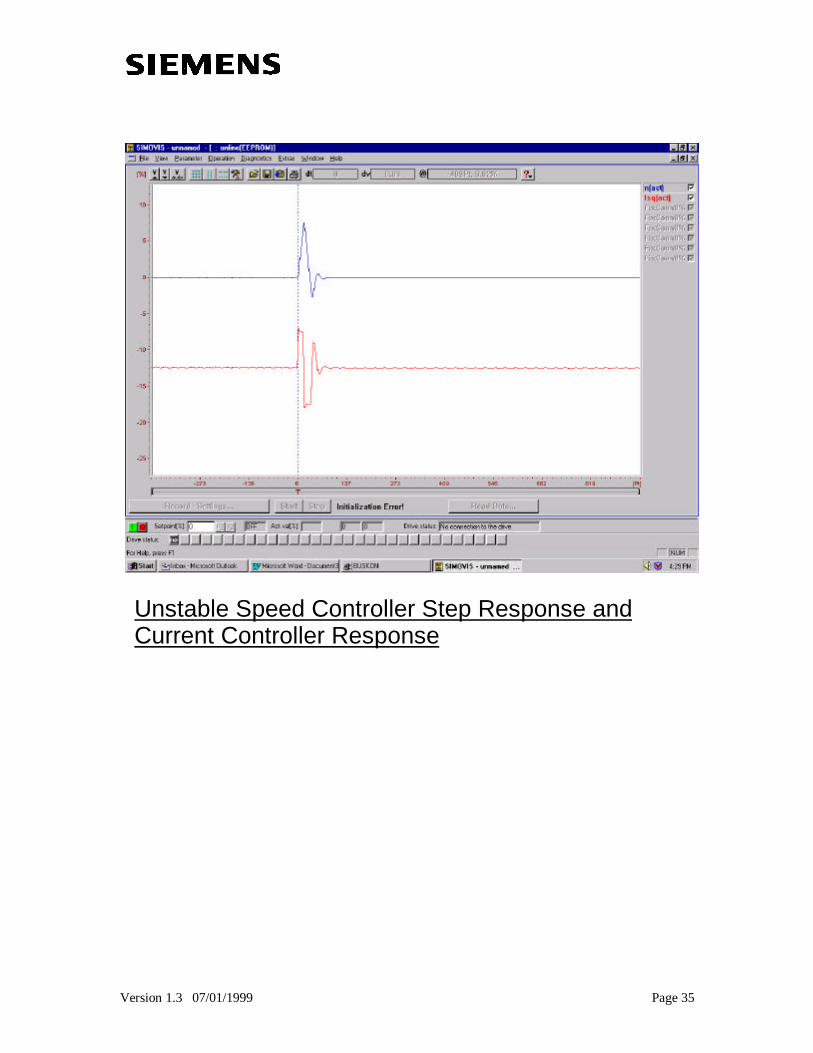
Unstable Speed Controller Step Response andCurrent Controller Response
Version 1.3 07/01/1999 Page 36
After P204 is OptimizedSet P206 = 250
Set a very long integration timeto cancel out residual errorwhich may occur over time.
Record values:P120-P125,235, 240,223, 204, 207, 206
Basic Speed Controller andPosition Controller TuningComplete.
Proceed to Technology Tuning
Note: When integration time is enabled, check to make sure that no overshootoccurs. If speed controller pre-control is properly adjusted theintegration time can actually be left off (P206=0 [340]).
Version 1.3 07/01/1999 Page 37
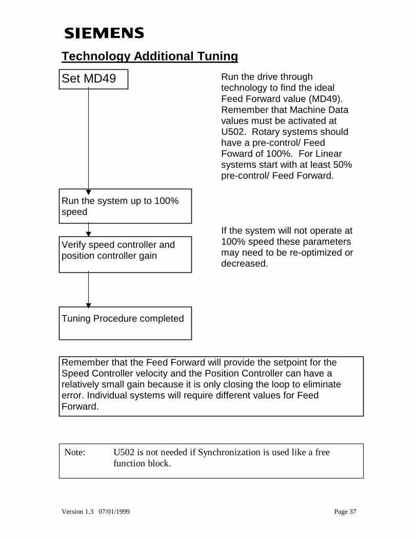
Technology Additional Tuning
Set MD49
Run the system up to 100%speed
Verify speed controller andposition controller gain
Run the drive throughtechnology to find the idealFeed Forward value (MD49).Remember that Machine Datavalues must be activated atU502. Rotary systems shouldhave a pre-control/ FeedFoward of 100%. For Linearsystems start with at least 50%pre-control/ Feed Forward.
If the system will not operate at100% speed these parametersmay need to be re-optimized ordecreased.
Tuning Procedure completed
Remember that the Feed Forward will provide the setpoint for theSpeed Controller velocity and the Position Controller can have arelatively small gain because it is only closing the loop to eliminateerror. Individual systems will require different values for FeedForward.
Note: U502 is not needed if Synchronization is used like a freefunction block.
Version 1.3 07/01/1999 Page 38
Section 3:Technology Options Quick
Setup Method
SIMOVERT MASTERDRIVES6SE70 MC
Motion Control
Version 1.3 07/01/1999 Page 39
MASTERDRIVE MOTION CONTROL:TECHNOLOGY OPTIONS QUICK SETUPMETHODTypical changes to Parameters needed for using TechnologyOptions.Intended to be used with function diagrams listed in [ ] .
Purpose:
The purpose of this document is to lead the user through a
typical setup of the Technology options for a MASTERDRIVE Motion
Controller. Follow through each of the steps, with the stated function
diagrams, and apply them to your individual setup. These steps will
lead you through general technology activation without the use of a
download file. The “Control flow sequence” and the “Activation &
Setting” sections illustrate the setup required for use with the
“Operating Mode Manager.” The individual setup of the drive control
and IO is left to the user. This should be used as a checklist for
connecting drive functions and performing required definitions.
Version 1.3 07/01/1999 Page 40
Technology Options QuickSetup MethodSection 3 Table of Contents:3.1 Default Drive
3.2 Set Motor Data
3.3 Verify Technology Activation
3.4 Choose Operating Mode Manager
3.5 Establishing Length Unit System
3.6 Control Flow Sequence
3.7 Activation and Settings
3.8 Verify and Define Common Machine Data
3.9 Homing Procedure Checklist
3.10 MDI Operation Checklist
3.11 Synchronism Method
3.12 Operation Signal Assertion
Version 1.3 07/01/1999 Page 41
3.1 Default Drive – Quick Startup Guide Section 1.2
3.2 Set Motor Data – Quick Startup Guide Section 1.3
3.3 Verify F01 Technology Activation [850]If n978 = 1 technology is activated.If n978 = 0 see [850].
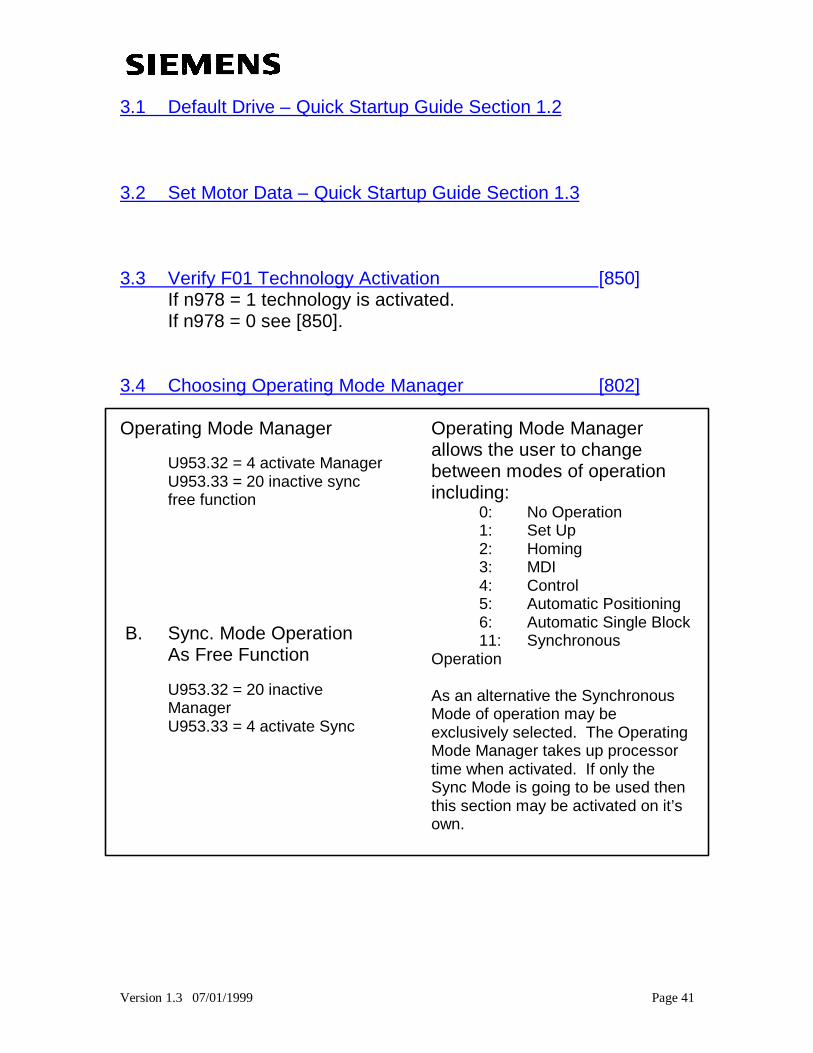
3.4 Choosing Operating Mode Manager [802]
Operating Mode Manager
U953.32 = 4 activate ManagerU953.33 = 20 inactive syncfree function
B. Sync. Mode OperationAs Free Function
U953.32 = 20 inactiveManagerU953.33 = 4 activate Sync
Operating Mode Managerallows the user to changebetween modes of operationincluding:
0: No Operation1: Set Up2: Homing3: MDI4: Control5: Automatic Positioning6: Automatic Single Block11: Synchronous
Operation
As an alternative the SynchronousMode of operation may beexclusively selected. The OperatingMode Manager takes up processortime when activated. If only theSync Mode is going to be used thenthis section may be activated on it’sown.
Version 1.3 07/01/1999 Page 42
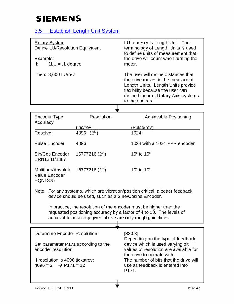
3.5 Establish Length Unit System
Rotary SystemDefine LU/Revolution Equivalent
Example:If: 1LU = .1 degree
Then: 3,600 LU/rev
LU represents Length Unit. Theterminology of Length Units is usedto define units of measurement thatthe drive will count when turning themotor.
The user will define distances thatthe drive moves in the measure ofLength Units. Length Units provideflexibility because the user candefine Linear or Rotary Axis systemsto their needs.
Encoder Type Resolution Achievable PositioningAccuracy (inc/rev) (Pulse/rev) Resolver 4096 (212) 1024
Pulse Encoder 4096 1024 with a 1024 PPR encoder
Sin/Cos Encoder 16777216 (224) 105 to 106
ERN1381/1387
Multiturn/Absolute 16777216 (224) 105 to 106
Value EncoderEQN1325
Note: For any systems, which are vibration/position critical, a better feedbackdevice should be used, such as a Sine/Cosine Encoder.
In practice, the resolution of the encoder must be higher than therequested positioning accuracy by a factor of 4 to 10. The levels ofachievable accuracy given above are only rough guidelines.
Determine Encoder Resolution:
Set parameter P171 according to theencoder resolution.
If resolution is 4096 ticks/rev:4096 = 2öûà P171 = 12
[330.3]Depending on the type of feedbackdevice which is used varying bitvalues of resolution are available forthe drive to operate with.The number of bits that the drive willuse as feedback is entered intoP171.
Version 1.3 07/01/1999 Page 43
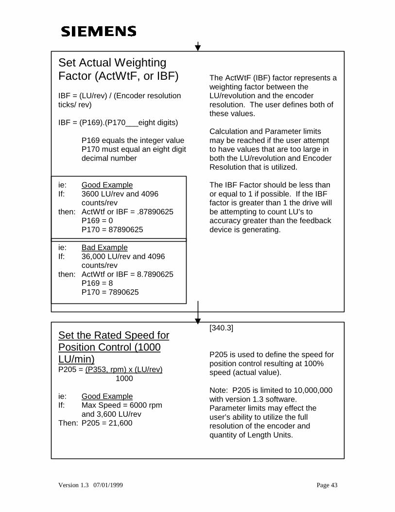
Set Actual WeightingFactor (ActWtF, or IBF)
IBF = (LU/rev) / (Encoder resolutionticks/ rev)
IBF = (P169).(P170___eight digits)
P169 equals the integer valueP170 must equal an eight digitdecimal number
ie: Good ExampleIf: 3600 LU/rev and 4096
counts/revthen: ActWtf or IBF = .87890625
P169 = 0P170 = 87890625
ie: Bad ExampleIf: 36,000 LU/rev and 4096
counts/revthen: ActWtf or IBF = 8.7890625
P169 = 8P170 = 7890625
The ActWtF (IBF) factor represents aweighting factor between theLU/revolution and the encoderresolution. The user defines both ofthese values.
Calculation and Parameter limitsmay be reached if the user attemptto have values that are too large inboth the LU/revolution and EncoderResolution that is utilized.
The IBF Factor should be less thanor equal to 1 if possible. If the IBFfactor is greater than 1 the drive willbe attempting to count LU’s toaccuracy greater than the feedbackdevice is generating.
Set the Rated Speed forPosition Control (1000LU/min)P205 = (P353, rpm) x (LU/rev)
1000
ie: Good ExampleIf: Max Speed = 6000 rpm
and 3,600 LU/revThen: P205 = 21,600
[340.3]
P205 is used to define the speed forposition control resulting at 100%speed (actual value).
Note: P205 is limited to 10,000,000with version 1.3 software.Parameter limits may effect theuser’s ability to utilize the fullresolution of the encoder andquantity of Length Units.
Version 1.3 07/01/1999 Page 44
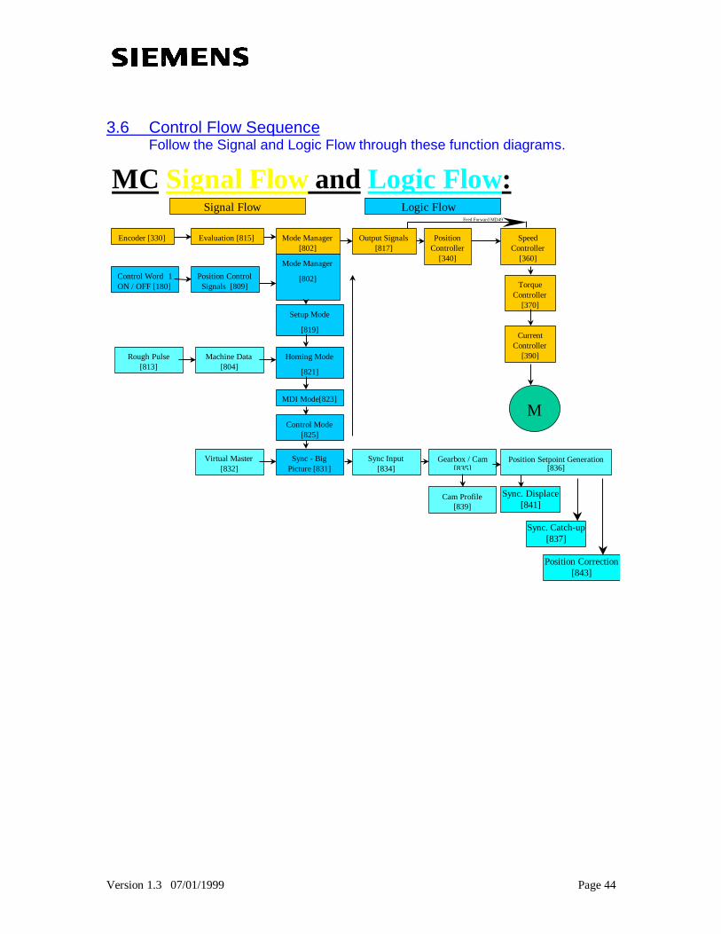
3.6 Control Flow SequenceFollow the Signal and Logic Flow through these function diagrams.
MC Signal Flow and Logic Flow :
Encoder [330] Evaluation [815] Mode Manager[802]
Output Signals[817]
PositionController
[340]
SpeedController
[360]
TorqueController
[370]
CurrentController
[390]
M
Control Word 1ON / OFF [180]
Position ControlSignals [809]
Setup Mode
[819]
Homing Mode
[821]
MDI Mode[823]
Rough Pulse[813]
Machine Data[804]
Control Mode[825]
Sync - BigPicture [831]
Virtual Master[832]
Sync Input[834]
Cam Profile[839]
Mode Manager
[802]
Signal Flow Logic Flow
Position Setpoint Generation[836]
Gearbox / Cam[835]
Sync. Displace[841]
Sync. Catch-up[837]
Position Correction[843]
Feed Forward MD49
Version 1.3 07/01/1999 Page 45
Function Diagram:
[809] Position Control Signals
Description:
This block is used as a control wordfor the Technology (F01). Modes ofoperation and control signals areassigned at this point.
[802] Operating Mode Manager Operating Mode Manager allows theuser to change between modes ofoperation including:
0: No Operation1: Set Up2: Homing3: MDI4: Control5: Automatic Positioning6: Automatic Single Block11: Synchronous
Operation
[819] Setup Mode Set-up Mode is used for positioncontrolled inching. Set-up Modetakes into account software limits forposition.
[821] Homing Mode Homing Mode is used to approach apredefined position. This position isused to define the reference systemfor the Axis. An external signal(BERO signal), such as a proximityswitch, will indicate when the Axis isin place.
[823] MDI Positioning Mode MDI mode is used for point to pointpositioning. MDI defines theacceleration, speed and position fora movement of the axis.
[825] Control Mode Control Mode is used for positioncontrolled inching. Control Mode issimilar to Set-up Mode but it doesNOT take into account softwarelimits for position.
Version 1.3 07/01/1999 Page 46
Function Diagram: Description:
[831] Synchronism Mode (overview) Synchronism Mode is used for thesynchronization of several axis’s.Functions such as Virtual Master,Engaging/Disengaging, Gear Ratio,Cam Table and Position Correctionare incorporated into thesynchronization functionality of theTechnology (F01).
[832] Synchronism Virtual Master The Virtual Master is used as areference for each axis to follow.The advantage of a Virtual Masterverses a Real Master is adisturbance free system.
The Virtual Master is given speedreference, initial position, resetsignals and start/stop signals.
[834] Synchronism Input andEngaging / Disengaging
The Master Axis Signal is assignedhere. Engaging and Disengagingrepresent a clutching function thatallows the Axis to match the masterand be ramped on and off.
[835] Synchronism Gearbox andCam Table
The Gearbox can be used to definea ratio between the Master Axis andthe following Axis.
[836] Position Setpoint Generation Position Setpoint and Speed Pre-Control signals are generated aftersignal has gone passed throughTechnology Options.
[837] Synchronism Catch-up function This function can be used toaccelerate the drive to the speed of arunning machine.
Version 1.3 07/01/1999 Page 47
Function Diagram: Description:
[839] Synchronism Cam Table The Cam Table can be used as amapping function between theMaster Axis and a following Axis.Profiles are loaded into the table andthe following axis can be set to followirregular motion profiles.
[841] Angular Sync & Displacement Used to Displace Angle Absolute,Relative or to match Master.
[843] Position Correction Used to correct for position errors bycomparing actual position to areference position.
Version 1.3 07/01/1999 Page 48
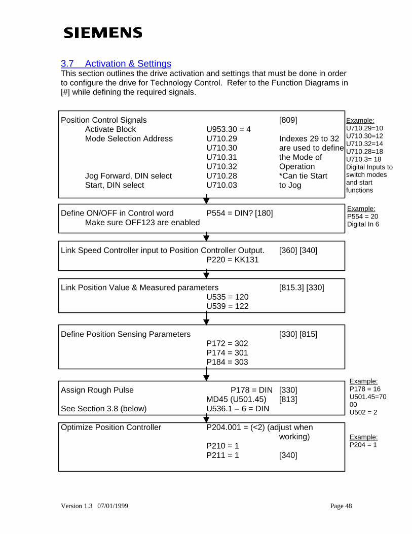
3.7 Activation & SettingsThis section outlines the drive activation and settings that must be done in orderto configure the drive for Technology Control. Refer to the Function Diagrams in[#] while defining the required signals.
Position Control Signals [809]Activate Block U953.30 = 4Mode Selection Address U710.29 Indexes 29 to 32
U710.30 are used to defineU710.31 the Mode ofU710.32 Operation
Jog Forward, DIN select U710.28 *Can tie StartStart, DIN select U710.03 to Jog
Define ON/OFF in Control word P554 = DIN? [180]Make sure OFF123 are enabled
Link Speed Controller input to Position Controller Output. [360] [340]P220 = KK131
Link Position Value & Measured parameters [815.3] [330]U535 = 120U539 = 122
Define Position Sensing Parameters [330] [815]P172 = 302P174 = 301P184 = 303
Assign Rough Pulse P178 = DIN [330]MD45 (U501.45) [813]
See Section 3.8 (below) U536.1 – 6 = DIN
Optimize Position Controller P204.001 = (<2) (adjust whenworking)
P210 = 1P211 = 1 [340]
Example:P554 = 20Digital In 6
Example:U710.29=10U710.30=12U710.32=14U710.28=18U710.3= 18Digital Inputs toswitch modesand startfunctions
Example:P178 = 16U501.45=7000U502 = 2
Example:P204 = 1
Version 1.3 07/01/1999 Page 49
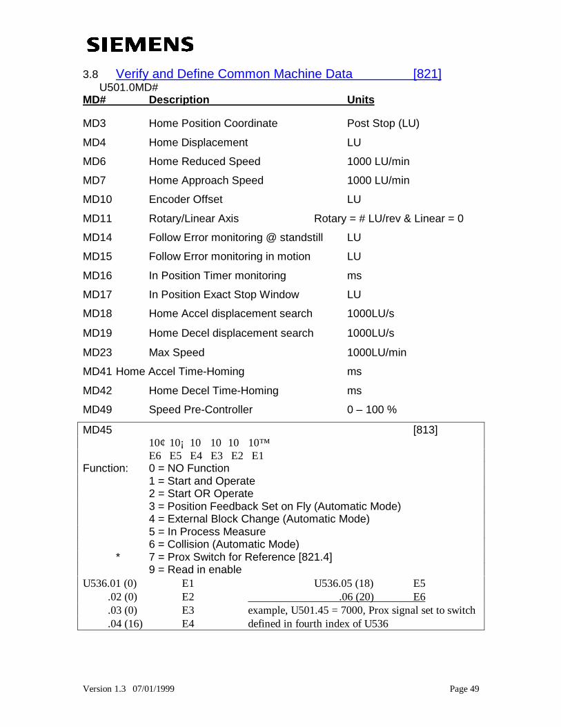
3.8 Verify and Define Common Machine Data [821]U501.0MD#
MD# Description Units
MD3 Home Position Coordinate Post Stop (LU)
MD4 Home Displacement LU
MD6 Home Reduced Speed 1000 LU/min
MD7 Home Approach Speed 1000 LU/min
MD10 Encoder Offset LU
MD11 Rotary/Linear Axis Rotary = # LU/rev & Linear = 0
MD14 Follow Error monitoring @ standstill LU
MD15 Follow Error monitoring in motion LU
MD16 In Position Timer monitoring ms
MD17 In Position Exact Stop Window LU
MD18 Home Accel displacement search 1000LU/sû
MD19 Home Decel displacement search 1000LU/sû
MD23 Max Speed 1000LU/min
MD41 Home Accel Time-Homing ms
MD42 Home Decel Time-Homing ms
MD49 Speed Pre-Controller 0 – 100 %
MD45 [813]10¢ 10¡ 10 10û10ö 10ôE6 E5 E4 E3 E2 E1
Function: 0 = NO Function1 = Start and Operate2 = Start OR Operate3 = Position Feedback Set on Fly (Automatic Mode)4 = External Block Change (Automatic Mode)5 = In Process Measure6 = Collision (Automatic Mode)
* 7 = Prox Switch for Reference [821.4]9 = Read in enable
U536.01 (0) ⇒ E1 U536.05 (18) ⇒ E5 .02 (0) ⇒ E2 .06 (20) ⇒ E6 .03 (0) ⇒ E3 example, U501.45 = 7000, Prox signal set to switch .04 (16) ⇒ E4 defined in fourth index of U536
Version 1.3 07/01/1999 Page 50
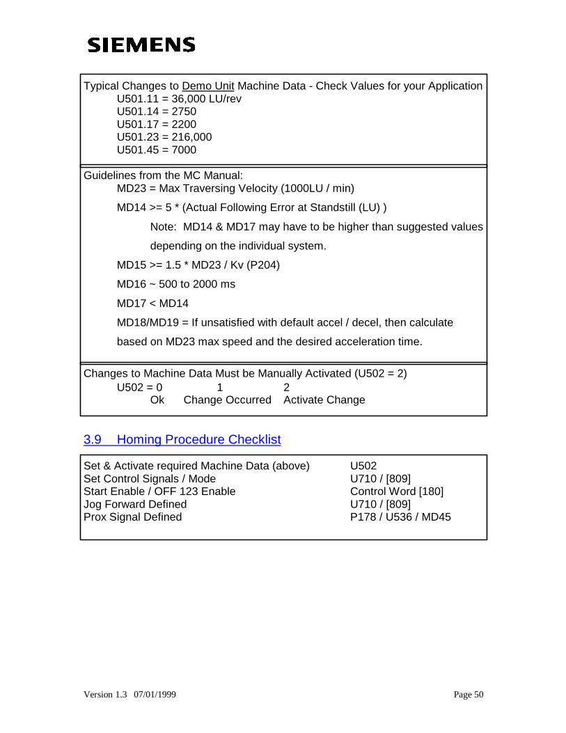
Typical Changes to Demo Unit Machine Data - Check Values for your ApplicationU501.11 = 36,000 LU/revU501.14 = 2750U501.17 = 2200U501.23 = 216,000U501.45 = 7000
Guidelines from the MC Manual:MD23 = Max Traversing Velocity (1000LU / min)
MD14 >= 5 * (Actual Following Error at Standstill (LU) )
Note: MD14 & MD17 may have to be higher than suggested values
depending on the individual system.
MD15 >= 1.5 * MD23 / Kv (P204)
MD16 ~ 500 to 2000 ms
MD17 < MD14
MD18/MD19 = If unsatisfied with default accel / decel, then calculate
based on MD23 max speed and the desired acceleration time.
Changes to Machine Data Must be Manually Activated (U502 = 2)U502 = 0 ⇒ 1 ⇒ 2
Ok Change Occurred Activate Change
3.9 Homing Procedure Checklist
Set & Activate required Machine Data (above) U502Set Control Signals / Mode U710 / [809]Start Enable / OFF 123 Enable Control Word [180]Jog Forward Defined U710 / [809]Prox Signal Defined P178 / U536 / MD45
Version 1.3 07/01/1999 Page 51
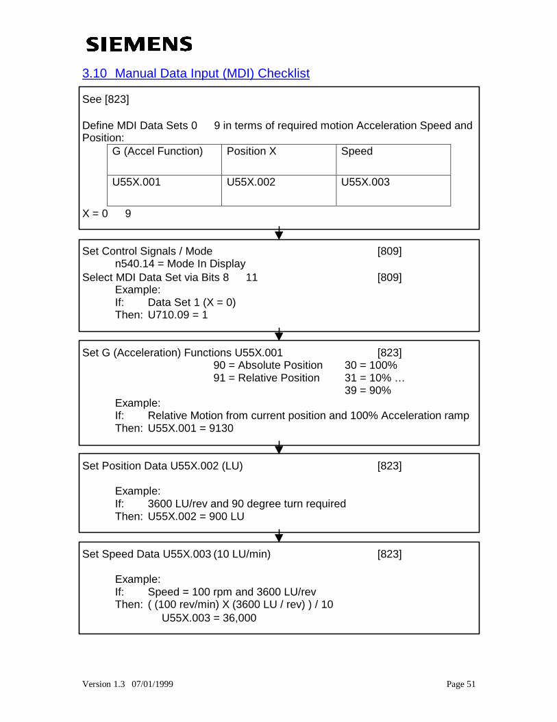
3.10 Manual Data Input (MDI) Checklist
See [823]
Define MDI Data Sets 0 ⇒ 9 in terms of required motion Acceleration Speed andPosition:
G (Accel Function) Position X Speed
U55X.001 U55X.002 U55X.003
X = 0 ⇒ 9
Set Control Signals / Mode [809]n540.14 = Mode In Display
Select MDI Data Set via Bits 8 ⇒ 11 [809]Example:If: Data Set 1 (X = 0)Then: U710.09 = 1
Set G (Acceleration) Functions U55X.001 [823] 90 = Absolute Position 30 = 100%
91 = Relative Position 31 = 10% …39 = 90%
Example:If: Relative Motion from current position and 100% Acceleration rampThen: U55X.001 = 9130
Set Position Data U55X.002 (LU) [823]
Example:If: 3600 LU/rev and 90 degree turn requiredThen: U55X.002 = 900 LU
Set Speed Data U55X.003 (10 LU/min) [823]
Example:If: Speed = 100 rpm and 3600 LU/revThen: ( (100 rev/min) X (3600 LU / rev) ) / 10
⇒ U55X.003 = 36,000
Version 1.3 07/01/1999 Page 52
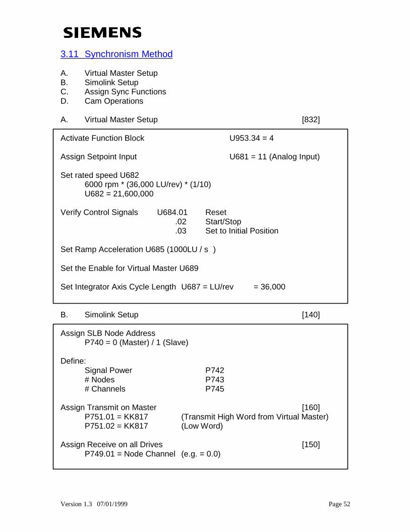
3.11 Synchronism Method
A. Virtual Master SetupB. Simolink SetupC. Assign Sync FunctionsD. Cam Operations
A. Virtual Master Setup [832]
Activate Function Block U953.34 = 4
Assign Setpoint Input U681 = 11 (Analog Input)
Set rated speed U6826000 rpm * (36,000 LU/rev) * (1/10)U682 = 21,600,000
Verify Control Signals U684.01 Reset .02 Start/Stop .03 Set to Initial Position
Set Ramp Acceleration U685 (1000LU / sû)
Set the Enable for Virtual Master U689
Set Integrator Axis Cycle Length U687 = LU/rev = 36,000
B. Simolink Setup [140]
Assign SLB Node AddressP740 = 0 (Master) / 1 (Slave)
Define:Signal Power P742# Nodes P743# Channels P745
Assign Transmit on Master [160]P751.01 = KK817 (Transmit High Word from Virtual Master)P751.02 = KK817 (Low Word)
Assign Receive on all Drives [150]P749.01 = Node Channel (e.g. = 0.0)
Version 1.3 07/01/1999 Page 53
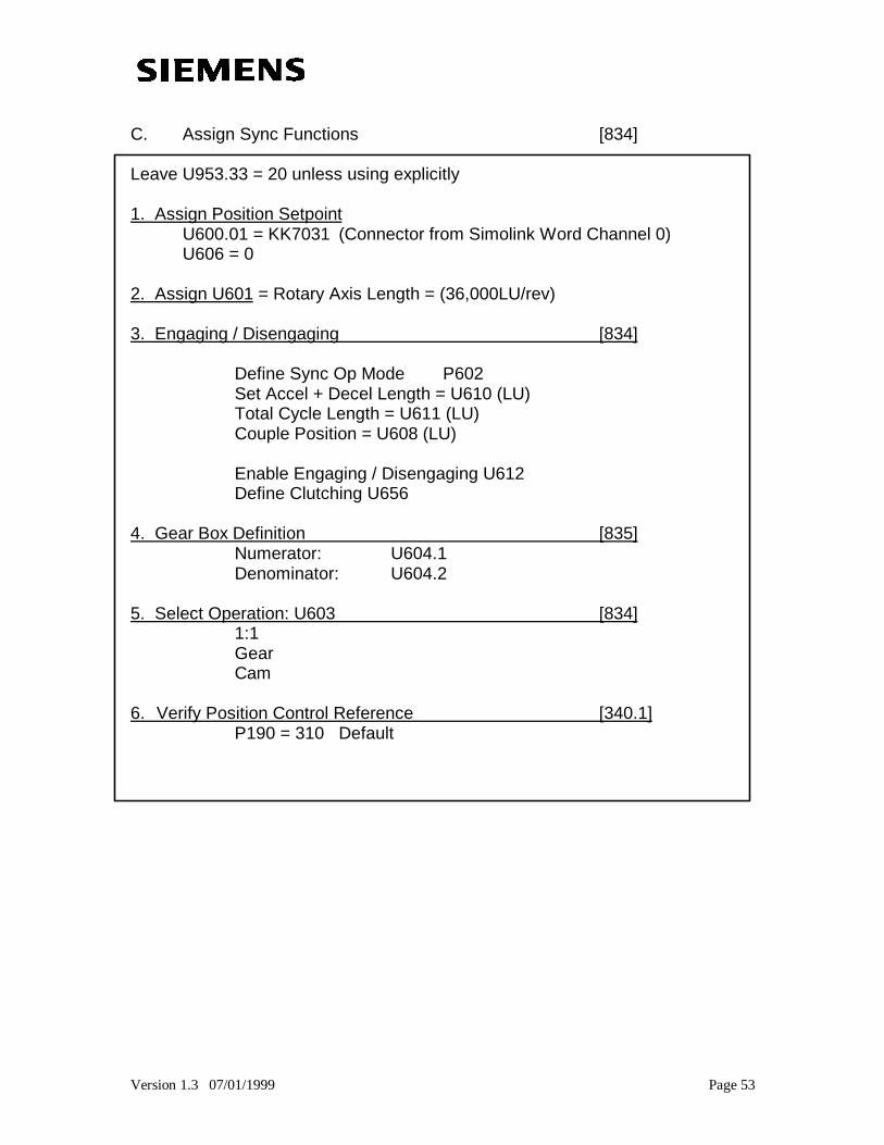
C. Assign Sync Functions [834]
Leave U953.33 = 20 unless using explicitly
1. Assign Position SetpointU600.01 = KK7031 (Connector from Simolink Word Channel 0)U606 = 0
2. Assign U601 = Rotary Axis Length = (36,000LU/rev)
3. Engaging / Disengaging [834]
Define Sync Op Mode P602Set Accel + Decel Length = U610 (LU)Total Cycle Length = U611 (LU)Couple Position = U608 (LU)
Enable Engaging / Disengaging U612Define Clutching U656
4. Gear Box Definition [835]Numerator: U604.1Denominator: U604.2
5. Select Operation: U603 [834]1:1GearCam
6. Verify Position Control Reference [340.1]P190 = 310 Default
Version 1.3 07/01/1999 Page 54
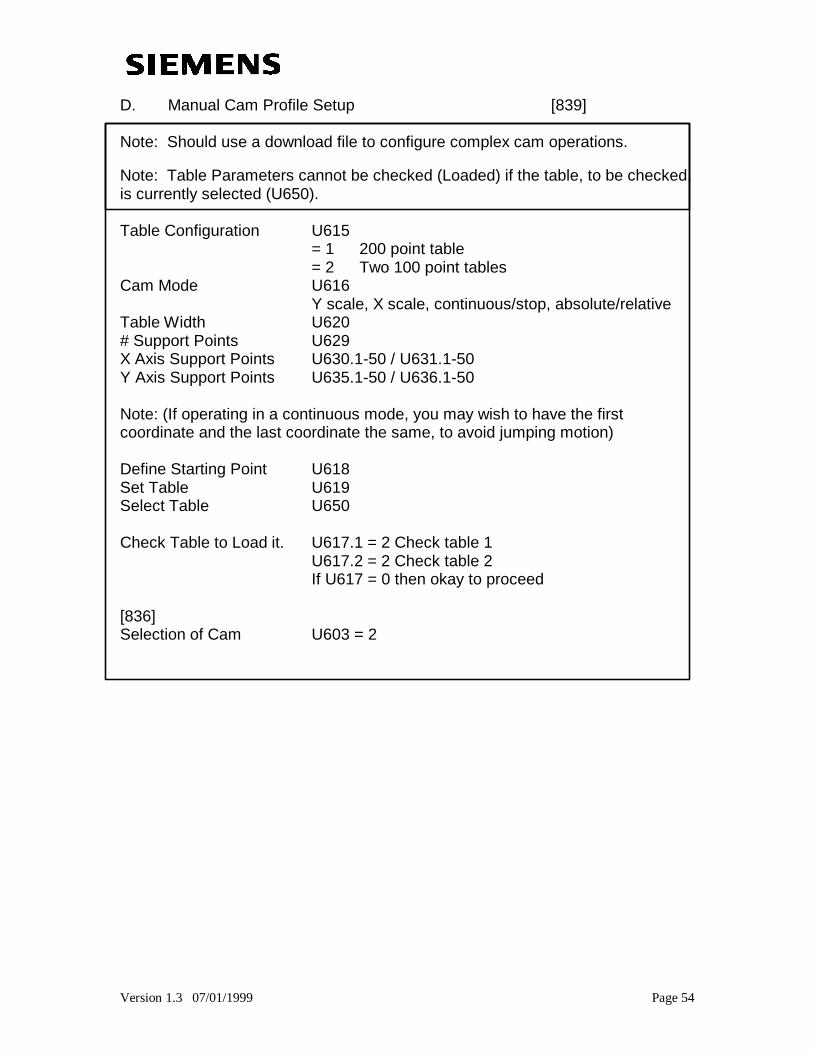
D. Manual Cam Profile Setup [839]
Note: Should use a download file to configure complex cam operations.
Note: Table Parameters cannot be checked (Loaded) if the table, to be checked,is currently selected (U650).
Table Configuration U615= 1 200 point table= 2 Two 100 point tables
Cam Mode U616Y scale, X scale, continuous/stop, absolute/relative
Table Width U620# Support Points U629X Axis Support Points U630.1-50 / U631.1-50Y Axis Support Points U635.1-50 / U636.1-50
Note: (If operating in a continuous mode, you may wish to have the firstcoordinate and the last coordinate the same, to avoid jumping motion)
Define Starting Point U618Set Table U619Select Table U650
Check Table to Load it. U617.1 = 2 Check table 1U617.2 = 2 Check table 2If U617 = 0 then okay to proceed
[836]Selection of Cam U603 = 2
Version 1.3 07/01/1999 Page 55
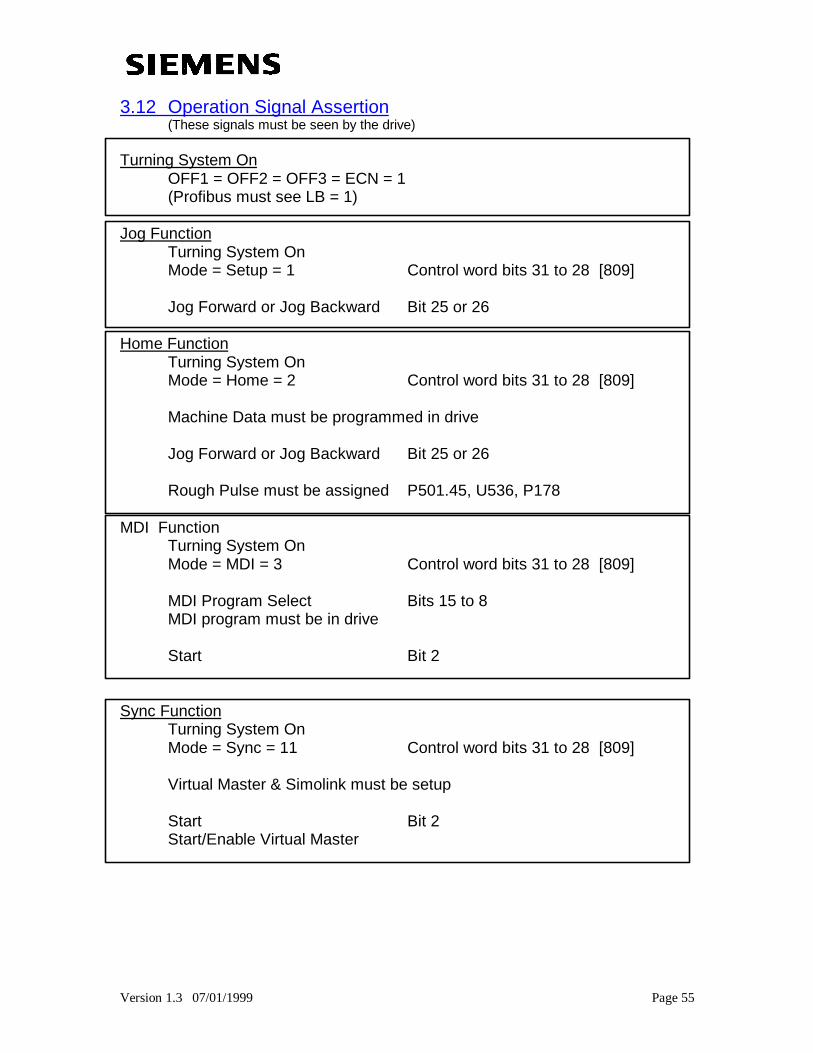
3.12 Operation Signal Assertion(These signals must be seen by the drive)
Turning System OnOFF1 = OFF2 = OFF3 = ECN = 1(Profibus must see LB = 1)
Jog FunctionTurning System OnMode = Setup = 1 Control word bits 31 to 28 [809]
Jog Forward or Jog Backward Bit 25 or 26
Home FunctionTurning System OnMode = Home = 2 Control word bits 31 to 28 [809]
Machine Data must be programmed in drive
Jog Forward or Jog Backward Bit 25 or 26
Rough Pulse must be assigned P501.45, U536, P178
MDI FunctionTurning System OnMode = MDI = 3 Control word bits 31 to 28 [809]
MDI Program Select Bits 15 to 8MDI program must be in drive
Start Bit 2
Sync FunctionTurning System OnMode = Sync = 11 Control word bits 31 to 28 [809]
Virtual Master & Simolink must be setup
Start Bit 2Start/Enable Virtual Master