qos enabled vertical handover in vehicular 4g...
TRANSCRIPT

I J C T A, 9(2) 2016, pp. 397-409© International Science Press
*1 Professor, CSE, Veltech Multitech Engineering College, Chennai, Tamilnadu, India2 Junior Research Fellow, Veltech Multitech Engineering College, Chennai, Tamilnadu, India3 Ph.D. Scholar, CSE, Anna University, Chennai, Tamilnadu, India
E-mail: [email protected]
Qos Enabled Vertical Handover in Vehicular4g NetworksA. Rengarajan*1, S. Rajasekaran2 and P. Kumaran3
SUMMARY
This paper intends to propose the use of Vehicle Access Wave Standards. It can drive various number of InformationTechnology services which are accessible for vehicles through IEEE 802.11 and IEEE 1609. This vehicle becomesan essential service handover. One of the service handover is Media Independent Handover which is based onvertical handoff scheme. Vertical handoff scheme to connect different access networks for interacting (both safetyand user application related information), VANET and vehicular users are used. At the time of intermingling,coinciding occurs in the area of heterogeneous networks. To eradicate this coinciding, VUs are allowed to dovertical handoff between several access networks. This vertical handoff plays a dynamic role in guaranteeing userquality of services and achieving enrichment of system performance. This vertical handoff scheme is functional inMIH. This MIH based vertical handoff scheme is used to upkeep multimedia services through inter-technologynodes. It is executed through NS3. From the performance analysis, dissimilar performance parameters such asnumber of throughput, delay, power consumption, and handoff are analyzed in heterogeneous wireless networks.Moreover to heighten these parameters, a new technique is proposed. This technique will heighten the performanceparameters by selecting only one network during vertical handoff session, and also the MOP is used to denotemultiple number of vertical handoff measures that will select the best available network over and done with enhancedparameter values such as latency of network should be least in the wireless network. This proposed work is simulatedusing NS3. The simulation outcome illustrations that the minimized handoff latency, maximum QoS and minimalcost during handover.
Keywords: Multiple Optimization Problem; Vertical handoff; Media Independent Handover; VANET (VehicularAd-hoc Network; QoS (Quality of Service)
1. INTRODUCTION
Vehicular Networks are based on the purposeful Intelligent Transportation Systems (ITS). The grippingresearch area of VANET’s is ad-hoc network. This VANET related research and applications are well-known considerations. In VANET, vehicular users can link different access networks for handover bothsafety and user application associated information. To upkeep this VU communication, the diverse accesstechnologies such as UMTS, WLAN and WiMAX are possible to integrate heterogeneously. At the time ofintermingling, intersecting arises in the area of various networks. Vehicular users may select the best networkto connect this interacted area of various access networks. For VUs having read one network, verticalhandoff, i.e., shifting from one to another can be executed for communication continuation or QoSenhancement. Performance analysis of VANET through simulation has been reviewed in the literatures inrecent years. In the review, the authors work on VANET simulation scenario built on network simulator(NS3) shows the effect of vehicle velocity, the distance between vehicles on the packet loss and throughputof the VUs. Though, in exercise, multiple access networks may heterogeneously combined in VANET.Thus estimating user communication performance scenario is highly desired [1]-[4]. In the security of

398 A. Rengarajan, S. Rajasekaran and P. Kumaran
vehicular network, developed actual techniques can have the potential to provide the public safety on theroads. These vehicular networks need an appropriate security design that will protect them from dissimilarkind of security outbreak.
Vehicular Network
To make a mobile network, Vehicular ad hoc network is used. In a MANET, VANET are used as carriagesmobile nodes [2]. These contributing cars in the VANET switch into a wireless node or router and thesecontributing carriages having network about 110 to 330 meters of respectively other can link and make anetwork with an extensive range. In case signal range doesn’t cover the carriages range, other carriages canbe added the link between the vehicles. By this way, a mobile Internet is made. For safety reasons, it can beevaluated in the first systems with police and fire vehicles. It is used to connect with each other by fit in thistechnology. An automotive corporation such as Daimler Chrysler, GM, BMW, Toyota, and Ford encouragesthis kind of tenure.
Necessitates for Handover
The next-generation wireless network is wished-for as a connection of dissimilar wireless networks beingLTE, WiMAX and Wi-Fi. These networks can provide the greatest facility to the mobile users anywhereanytime. So, challenge across various access networks is supporting terminal seamless handoff. It is one ofthe most critical factors for next-gen wireless network [6], [7]. The vertical handoff also named asHeterogeneous handoff method. It is usually designated in three stages: first one is handoff initiation, andthe second is handoff decision and the last one is handoff execution. In the first phase of heterogeneoushandoff method i.e. handoff initiation, all the essential information’s are gathered from applicant networks.This phase is named as handoff initiation (network discovery) phase. And the second phase of hand- offmethod is hand- off decision phase. Using this phase, it can be calculated as how to perform the handoff byevaluating and selecting the most proper access network. All the processes are done in the hand- off decisionphase. It is also termed as network selection phase [8]. The third one is handoff execution phase which isused to vary the channels and to combine with the objective network [10], [12]. It is the intelligent part ofvertical handoff process. Thus, handoff decision phase plays a vital role in the heterogeneous handoffmethod.
Figure 1: Overview of Handoff classifications

Qos Enabled Vertical Handover in Vehicular 4g Networks 399
Horizontal Handover
To upkeep the similar network technology, the horizontal handover process is used. The horizontal handoveris the handoff process of a terminal of mobile among access points shown in Figure-2 below. E.g., thechangeover of the transmission signal is examined as a horizontal handoff procedure from the base stationof IEEE 802.11b to a physically adjacent base station of IEEE 802.11b. Figure-2 Describes how hand offprocess takes place between the same networks. Normally, certain quality link condition constraints beingSNR, RSSI, and so on drip under a defined handoff threshold are considered by horizontal hand off decision[9].
Figure 2: Before and after handoff of Horizontal
Vertical Handover
To upkeep the dissimilar network technologies; the vertical handover process is used. The Vertical Handoveris the handoff procedure of a terminal of the mobile between access points having dissimilar networktechnologies as shown in Figure-3. E.g., the changeover of transmission signal is defined as a verticalhandoff method from the base station of IEEE 802.11b to the coincided cellular network Table I.
Figure 3: Vertical Handoff

400 A. Rengarajan, S. Rajasekaran and P. Kumaran
Table IDifference between vertical and horizontal handover
Parameter Horizontal handover Vertical Handover
IP address Changed Changed
Access Technology No change Changed
Network Interface No change Can be changed
QoS Parameter No change Can be changed
Figure 3 describes how to hand off takes place between the dissimilar networks. Table-I describes thebasic difference between horizontal and vertical handover function.
Vertical Handoff Decision
In overall, the three key steps are incorporated in the VHO process. First one is system discovery. Secondone is handoff decision and third one is handoff execution. The mobile stations are equipped with frequentinterfaces in the step of system discovery. By using these interfaces, Utilizing these interface, the networkand service accessibility in all the networks can be elected. These wireless networks are used to broadcastthe constant data rates for dissimilar services. The outcome will be based on various constraints or handoffmetrics with the accessible bandwidth convey power, delay, access cost, jitter, battery status of the mobiledevice and the user’s favourites. Lastly, to re-route the connection from the current network and the freshnetwork is a unified manner, handoff execution phase is used [13], [15].
Output A: The stable statuses show that the quality of link, WLAN is suitable and there is no pendingrequisite handoff.
Output B: The unstable state-Alert shows that the WLAN signal is fading and approaching the transitionregion. To allow the application for making handoff and HDE is used for growing buffer size and possiblyupdate upper layer protocols such as to adapt the TCP congestion, window size or other techniques inhandoff to increase the performance analysis.
Output C: Poor mean Handoff which shows that a handoff is wanted and the handoff process to theoverlay network (UMTS) is implored.
Handoff Procedure
The four phases of the entire signalling procedure of vertical handoff:
(1) Scanning of the new network interface;
(2) Invention of the new access router;
(3) Entry of the fresh network;
(4) The Routing intelligence apprising
The MN can transmit or receive information data packets over the new network interface, once theseprocedures are performed.
2. LITERATURE SURVEY
Vertical Handover Survey
The performance of Vertical handoff of VUs in a VANET scenario has dissimilar integrated UMTS andWLAN which have calculated based on network simulator 2 (NS2) [2]. To access both networks and MIH-
Qos Enabled Vertical Handover in Vehicular 4g Networks 401
based vertical handoff scheme, Multi-mode nodes are accessed and are executed in NS2 [10]. The VANETbased study and applications have established huge attentions. In VANET, VUs can be attached dissimilaraccess networks for conveying both user and safety application related information. To guarantee the userQoS and to achieve enhancement in terms of system performance, vertical handoff plays a vital role. So itmust be reviewed and valued thoroughly. VANET is an effective tool for estimating the performance. Dueto the long period and high cost, the approach may not be practicable [9]; alternatively, to make the processof vertical handoff and to estimate the performance and the simulation can be done in VANET. Performanceanalysis of VANET through simulation has been reviewed in the literature in recent years [15] and in thisreview, the authors work on VANET simulation scenarios built on network simulator (NS3) and shows theeffects of vehicle velocity, the distance between vehicles on the packet loss and throughput of VUs. Though,in exercise, multiple access networks may heterogeneously combined in VANET, thus estimating usercommunication performance below such scenario is highly desired. Also in previous works, the mobility isextremely simplified, which may strictly bind the simulation performance of the accuracy and efficiency[11].
Attributes MeNB Pico Cell HeNB Wi-Fi
Base Station Installation Mobile Operator Mobile Operator Subscriber Customer
Site Acquisition Mobile Operator Mobile Operator Subscriber Customer
TransmissionRange 300-2000m 40-100m 10-30m 100-200m
Band License Licensed Band Licensed Band Licensed Band Unlicensed Band
System Bandwidth 5,10,15,20 MHz 5,10,15,20 MHz 5,10,15,20 MHz 5,10,20 MHz
Transmission Range Up to 1 Gbps Up to 300 Mbps 100 Mbps – 1 Gbps Up to 600Mbps
Power consumption High Moderate Low Low
Problem Statement
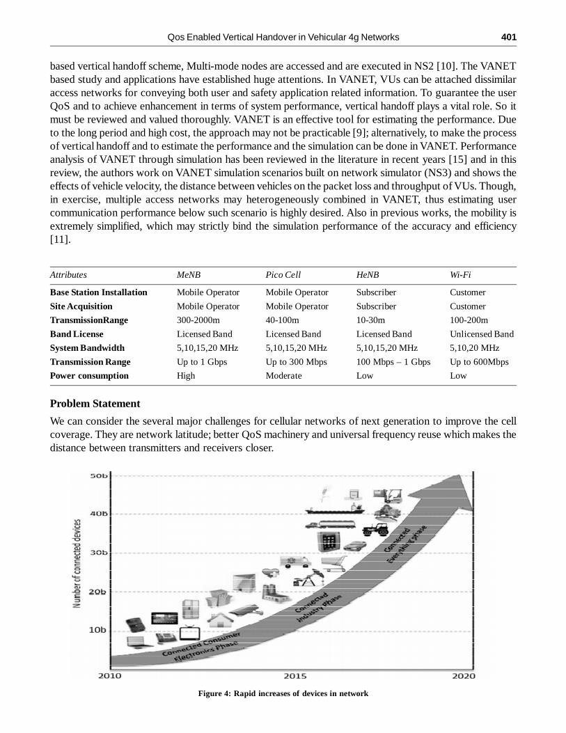
We can consider the several major challenges for cellular networks of next generation to improve the cellcoverage. They are network latitude; better QoS machinery and universal frequency reuse which makes thedistance between transmitters and receivers closer.
Figure 4: Rapid increases of devices in network

402 A. Rengarajan, S. Rajasekaran and P. Kumaran
The complete wireless accessing device plays a vital role to encounter the condition and to adopt theVertical Handoff to enhance the QoS due to demand in future generation.
3. OUR APPROACH
To encounter the QoS enhancement in Wireless Access technologies, our main motive is to part the signalin the small data rate signal to large data rate signal portion. As we all see that the Wi-Fi and LTE fits tounlicensed and licensed band structure accordingly. By comparing these licensed and unlicensed smallcells, we can conclude with this i.e. the small cell fits to licensed bands which consists of 3GPP, 3GPP2,WiMAX, and unauthorized small cells (e.g. Wi-Fi) [8]. To achieve QoS enhancement, flawless continuityover the large-scale networks for handoff, mobility and enhanced security, we will offer care for legacy. Inthe enlargement of the indoor analysis, our main motive is to focus on cell placement. In this we have tostudy Pico cells to progress the capacity of the network. By removing the coverage holes in a homogeneoussystem, these Pico cells are generally positioned. The Pico cells coverage areas are usually differs among40 m to 75 m. The Pico cells are made up of Omni directional antenna. To provide the well indoor coverageto the UE’s, can take the Omni directional antenna with 5dBi antenna gain. Low power compact basestations are elucidated using Pico cell and outdoor short range BS are described by using microcell.
Using short range BS we can enhance the coverage for both short and long distance users whereas themacro coverage is insufficient. To offer huge capacity area, the metro cell is modelled. In the case of Wi-Fi,we can access points which are working in the unlicensed band as well. To provide enhanced spectrumefficiency and coverage, handoff capabilities are proposed. While the base station of other macro cell orMeNB signal is powerless. A femto cell offers the high data rate, enhanced QoS and to communicate withthe distance macro cell base station such as Wi-Fi.
Our Motivation
� Higher data rate and enhanced QoS to subscribers
� Removing coverage gap in macro cell footprint
� Reducing Macro cell load
� Mitigate spectrum underutilization problem.
Comparisons among different radio base stations in LTETable II. Difference between radio base stations in LTE
4. SYSTEM MODULES
Antenna Patterns
The equation of azimuth antenna pattern of the single cell is demonstrated as:
� �2
3
min 12 ,� �� ��� �� � � � ��� �� �� �
mdB
A A
Where �3dB
= 70 degrees, Am = 20 dB. The patterns of the azimuth antenna for UEs and HeNBs are considered
to be Omni directional.
Path Loss Models
The deployments of the Path loss models are specified below. When the Tx-Rx parting is larger than orequal to 1m, the path loss models can put on, otherwise the following formula can be used with nosurveillance, which offers unique results to the 2 GHz capacities.

Qos Enabled Vertical Handover in Vehicular 4g Networks 403
PL (dB) = 38.46 + 20 log10R + 0.7d2D
Where the distance between the cells are denoted as D in m
Deployment
The deployment of path loss models are proposed as follows,
� R is the Tx-Rx separation in UE to HeNB.
� UE is inside the similar house as HeNB. Using the losses of free space and penetration which areproduced due to internal walls and floors, the path loss is displayed during that time. Due to internalwalls, the loss is executed as a log-linear value and is equal to 0.7dB/m.
� In UE to HeNB, UE is outside during that times the path loss modeling takes into account of d2D,indoor is the distance inside the house.
� In UE to HeNB, UE is inside the different house as HeNB during that time d2D, Low, 1 and Low, 2 arethe penetration losses of outdoor walls for the two houses.
Handover Request Procedures
� Acknowledgement procedure of Handover Request
� Transfer procedure of SN Status
� Release procedure of UE Context
Figure 5 stretches Sequence diagram of the X2-based handover below which displays the communicationof the objects of the X2 model in the simulator. When the UE or eNodeB is changed to another RRC state,the shaded labels specify the moments. Within the handover procedure, two timers are also displayed bythe figure: to maintain the handover leaving timer, the source eNodeB is used, at the same time to maintainthe handover joining timer, the target eNodeB is used.
Figure 5: Sequence diagram of the X2-based handover

404 A. Rengarajan, S. Rajasekaran and P. Kumaran
Though, in the present version of LTE module, there is no good handling of handover failure. In orderto evade handover failure, users must adjust the simulation correctly. Or else unpredicted behaviour mayhappen. To know this detail and for certain tips about this matter, refer the session of the tuning simulationalgorithm through handover process of the Consumer Documentation. The entity of the X2 model is theone that practices services from: The X2 interfaces,
� On the topmost point-to-point devices, they are executed as Sockets.
� To transmit/receive X2 messages, X2 interfaces of X2-C and X2-U interfaces to the peer eNB areused and also interfaced the application of S1.
To catch certain information desirable for the Elementary Actions of the X2 messages, X2 interface isused and it delivers these service systems to:
� The RRC entity (X2 SAP)
� To transmit/receive RRC messages
In the X2 message, the X2 entity transmits the RRC message as a transparent container. This messageof RRC is transmitted to the UE. Figure-6 gives execution Model of X2 object and SAPs displays theimplantation ideal of the X2 entity and its connection by all the other units and facilities in the protocolload. In the beginning of the handover method, the RRC entity is achieved. In the Handover Managementsub module of the eNB RRC entity, this RRC entity of handover method is implemented [9]. Some AdmissionControl events are achieved by the target eNB. This process is executed in the Admission Control submodule. This sub module will take any handover request originally.
Figure 6: Implementation model of X2 entity and SAPs
Design Issues
In contrast, the mobility between UMTS and WIFI is mentioned to partly intersecting handover and whenthe speed of the terminal of mobile is high, handover must be finished quickly to preserve the direct link.This affects large drop of packet and data rate, whereas the handover ensues between the UMTS and WIFI

Qos Enabled Vertical Handover in Vehicular 4g Networks 405
network [3], [10]. So, providing an efficient handover management and seamless service systems tosubscribers in vertical handover is the aim of our process. Below Figure-7 shows issues in design of verticalmobility architecture.
Figure 7: System architecture design issues in Vertical mobility
PROPOSED VERTICAL HAND-OFF
In our proposed work, the two stages of handoff procedure are stated as follows: Handoff of Layer 2(L2)and Layer 3(L3). The real transfer of means of communication connecting flanked by two unlike networkcrossing points is handoff of L2. To care the L2 handoff, L3 handoff is used by executing packet defendingand rerouting. When MNs move within the same domain, they do not alter their IP addresses, in our systemmodel. IP packets are addressed to an MN. Through the Internet, these MNs are routed to the WGW andnext to the MN during the Intra-Mesh Router. To come across the next-hop (to where the WMR must aheadthe data), the WMR checks the terminus IP address of a received packet. The physical interface is used toshow the third piece. Within the substantial crossing point, the WMR supposed to be used to ahead thedata. The WMR will practice the fixed next-hop to onward the data, if the target of the IP address absent inthe stand list [19], [20].
New Access Router Discovery
By the scanning process of new network interface, a new BS or AP is sensed once. The second process isthat the MN attempts to learn the information of WMR. The MN requests the new information of WMRfrom the information presently related with WMR by the use of new 802.11 APID or 802.16 BSID [18].That present related WMR is as well named as earlier WMR (PWMR) in handoff method. The MN isdemanding toward handoff among Inter Mesh Routers within dissimilar domains, as soon as the MNobtains the PrRtAdv communication which comprises a dissimilar HA’s IP address as of its individual[19].

406 A. Rengarajan, S. Rajasekaran and P. Kumaran
Novel Network Admission
In common, the part of the new network entry process is new network interface scanning. We place theinnovative system crossing point scrutinizing to an entity phase based on the different effect to the verticalhandoff. It is chiefly fretful so as to how the connection layer association is locate up subsequent to thenovel system crossing point examining and a handoff choice in this stage.
5. IMPLEMENTING MIH-BASED VERTICAL HAND-OFF SCHEME AND MULTI-MODE INNS3
MIH-Based Handover Strategy
IEEE 802.21 Working Cluster proposes the framework of MIH to avoid the performance detraction ofnetwork selection and vertical handover due to the heterogeneous characteristics of access networks, andto achieve seamless handover when user terminals roam among heterogeneous networks. In the framework,a new protocol layer, i.e., MIH layer between data link layer and network layer is proposed which hasseveral elements comprising MIH function, service access points, MIH users, etc. Figure 9 shows the MIH-based information interaction between a MN and an access point (AP).
Figure 8: Overall Architecture Diagram
To execute MIH-based vertical handoff in varied networks, a heterogeneous network handover platformcomprising of MIH modules must be established. The handover platform of MIH module mainly composedof both MIHF module and MIH User module. When MN enters the coverage area of one particular network,it must be able to spot the network information in time, this can be attained by ND mechanism, i.e., users

Qos Enabled Vertical Handover in Vehicular 4g Networks 407
notice route advertisement messages periodically broadcasted by the network in a heterogeneously integratednetwork of various access networks [16]. Based on which, the users controls whether a handover must beperformed or not. If yes, consistent control commands will be sent to low layer to start handoff.
6. PERFORMANCE ANALYSIS-QOS
The existing flows of QoS must be preserved efficiently by calculating approximately the attainable throughputof every traffic flow and evading the overloading channel. Depends on the IEEE 802.11e, we can go for theadmission control structure which is measurement-based one. This scheme is used for service of differentiationof the EDCA. To take conclusions on reception or rejection of a stream of voice, we have to listen MNs toavail budgets from the AP for voice traffic. To get good differentiation between dissimilar access groups andhigh-quality fairness between real-time streams inside the similar access group, this centrally-assisted distributedadmission control is supplied. The schemes of admission control and scheduling are significant in the networkof 802.16 and WLAN. But the particulars of the decision of admission control scheme cannot get through thenetwork of 802.16 and the details are given to the manufacturers [21]-[23].
Figure 9: MIH-based information interaction between a mobile Node and an Access Point
Figure 10: NS3 NetAnim .xml file output animation with 10 nodes

408 A. Rengarajan, S. Rajasekaran and P. Kumaran
7. CONCLUSION
We improve an extensible simulation environment combining a simulation tool NS3. MIH-based verticalhandoff scheme and multi-mode node model are established inNS3 and the communication performancesof multi-mode VU sin the heterogeneously integrated network of UMTS and WLAN is evaluated. Theimpacts of user velocity, the strength of traffic load and the type of handoff mechanisms on the communicationperformance of VUs are examined. Even though, the frequent handoff resulted from high velocity of usersmay degrade user QoS in terms of packet loss and handoff latency. Furthermore, while the light traffic loadof other users may not affect user performance severely, the heavy traffic load will degrade user performance,especially in WLAN. Comparing user performance during downward handoff and upward handoff, it isclear that the handoff latency resulted from upward handoff is much larger than that of downward handoff.
ACKNOWLEDGEMENT
Authors deliver their graduate to SERB (Young Scientist Scheme, No. SP/FTP/ETA-51/2013) Govt. of India for FinancialAssistance and FIST F.NO: SR/FST/College-189/2013
REFERENCES[1] I. F. Akyildiz, X. Wang, and W. Wang, “Wireless mesh networks: a survey”, Computer Networks, vol. 47, no. 4, pp. 445-
487, 2005.
[2] Dawei Mu, 2013[1] “Vertical Handoff Modeling and Simulation in VANET Scenarios” IEEE conf. 24-26 Oct. 2013 pp. 1-6.
[3] Jee-Young Song, Sung-Won Lee, Dong-Ho Cho, ‘Hybrid coupling scheme for UMTS and wireless LAN interworking’,IEEEconference, 2003.
[4] P. Kavitha and M. Santhalakshmi, “Enhanced QOS Factors for Load Balamced Handoff WiMax Net”, International Journalof Computer Application, Vol. 43, No. 24, April, 2012.
[5] Dimitrakopoulos, G; Dept.of Info. & Telematics, Harokopion Univ. of Athens, Athens, Greece, “Intelligent transportationsystems based on Internet-connected vehicles: fundamental Research Areas and Challenges”, IEEE Conf. 23-25 Aug.2011, pp. 145-151.
Figure 11: Simulation overview: Vertical handoff, using the constant velocity for the nodes

Qos Enabled Vertical Handover in Vehicular 4g Networks 409
[6] M. Buddhikot, G. Chandranmenon, S. Han, Y.W. Lee, S. Miller, and L. Salgarelli, “Integration of 802.11 and third-generation wireless data networks,” INFOCOM 2003, IEEE.
[7] Akyildiz, I.F, McNair, J, Ho, J.S.M, Uzunalioglu, H, “Mobility management in next-generation wireless systems,”Proceedings of the IEEE, vol. 87, Issue, 8, pp. 1347-1384, Aug. 1999.
[8] Kire jakimoski Toni Janevski, “Vertical Handover decision Algorithm from WiMAX to WLAN based on the Mobilenode’s speed and the session’s Priority”, International Journal of Advanced Science and Technology, vol. 49, December-2012.
[9] Rajinder Singh, Vikramjit Singh and Malti Rani “Implementing Horizontal Handover among Homogeneous Network inWiMAX”, IJAIEM, 2014.
[10] R. Good and N. Ventura, “A multilayered hybrid architecture to support vertical handover between IEEE 802.11 andUMTS”, International conference on Wireless Communications and Mobile Computing, 2006.
[11] Vicramjit Singh, Jyotsna sengupta, “Performance Analysis of Vertical Handover between Heterogeneous Networks,” inProc. International Conference on Advance Management and Technology (iCAMT 2013), 2013, pp. 15-18.
[12] Sukyoung, Youngsong Mun, “Improved Fast Handovers for Mobile IPv6 over IEEE 802.16e Networks,” Springer BerlinHeidelberg, May. 2007.
[13] Mark Stemm and Rendy H. Katz “Vertical handoffs in wireless overlay networks,” Mobile Networks and Applications,vol. 3, no. 4, pp. 335-350, 1998.
[14] Srikant Sharma, Inho Baek, Yuvrajsinh Dodia, and Tzi-cker Chiueh, “Omnicon:a mobile ip-based vertical handoff systemfor wireless LAN and GPRS links,” Compuer Science and Depertment, Stony Brook University.
[15] W. Wu, N. Banerjee, K. Basu, and S. K. Das, “SIP-based vertical handoff between WWANs and WLANs,” IEEE WirelessCommunications, vol. 12, no. 3, pp. 66-72, Jun. 2005.
[16] Simone Frattasi, Ernestina Cianca, and Ramjee Prasad, “An Integrated AP for Seamless Interworking of Existing WMANand WLAN Standards,” Springer US.
[17] Ghassan. M. T. Abdulla, Mosa Ali Abu-Rgheff and Sidi Mohammed Senouci, “Current trends in vehicular ad hocnetworks”, Ubiquitous Computing and Communication Journal.
[18] Dr.A.Rengarajan, S.Rajasekaran and P.Kumaran “Incorporation of Security Features in Agonistic Application Protocol inthe Web Search”, Middle-East Journal of Scientific Research 23(9): 2051-2059, 2015.
[19] Debashis Saha, Amitava Mukherjee, Iti Saha Misra, Mohuya Chakraborty, and Netaji Subhash, “Mobility support in IP: asurvey of related protocols,” IEEE Network, vol. 18, no. 6, pp. 34-40, Nov./Dec. 2004.
[20] Mohammad Jalil Piran, G. Rama Murthy and G. Praveen Babu, “Vehicular Ad Hoc and Sensor Networks; Principles andChalleges,” International Journla of Ad hoc, Sensor & Ubiquitiois Cmputing.
[21] Cheng Wei Lee, Li Ming Chen, Meng Chang Chen, and Yaali Sunny Sun, “A framework of handoffs in wireless overlaynetworks based on mobile IPv6,” IEEE Journal on Selected Areas in Communications, vol. 23, no. 11, pp. 2118-2128,Nov. 2005.
[22] Jing Nie, JiangChuan Wen, Qi Dong, and Zheng Zhou, “A seamless handoff in IEEE 802.16aand IEEE 802.11n hybridnetworks,” IEEE Communication, Circuit and Systems, 2005. http://ieeexplore.ieee.org/xpl/freeabs_all.jsp?arnumber=1493430&abst ractAccess=no&userType=inst
[23] Kyung-ah Kim, Chong-kwon Kim, and Tongsok Kim, “A Seamless Handover Mechanism for IEEE802.16e BroadbandWireless Access,” Springer Berlin Heidelberg, 2005.