qb-v850e2fx4h-pd in-circuit emulator user's manual · qb-v850e2fx4h-pd in-circuit emulator...
TRANSCRIPT

All information contained in these materials, including products and product specifications, represents information on the product at the time of publication and is subject to change by Renesas Electronics Corp. without notice. Please review the latest information published by Renesas Electronics Corp. through various means, including the Renesas Electronics Corp. website (http://www.renesas.com).
QB-V850E2FX4H-PD In-Circuit Emulator
User’s Manual
Rev.4.00 Sep 2014
Target Devices V850E2/FG4 V850E2/FJ4 V850E2/FK4 V850E2/FL4 V850E2/FF4-M V850E2/FK4-H V850E2/FL4-H V850E2/FK4-G

Notice 1. Descriptions of circuits, software and other related information in this document are provided only to illustrate the operation of
semiconductor products and application examples. You are fully responsible for the incorporation of these circuits, software, and information in the design of your equipment. Renesas Electronics assumes no responsibility for any losses incurred by you or third parties arising from the use of these circuits, software, or information.
2. Renesas Electronics has used reasonable care in preparing the information included in this document, but Renesas Electronics does not warrant that such information is error free. Renesas Electronics assumes no liability whatsoever for any damages incurred by you resulting from errors in or omissions from the information included herein.
3. Renesas Electronics does not assume any liability for infringement of patents, copyrights, or other intellectual property rights of third parties by or arising from the use of Renesas Electronics products or technical information described in this document. No license, express, implied or otherwise, is granted hereby under any patents, copyrights or other intellectual property rights of Renesas Electronics or others.
4. You should not alter, modify, copy, or otherwise misappropriate any Renesas Electronics product, whether in whole or in part. Renesas Electronics assumes no responsibility for any losses incurred by you or third parties arising from such alteration, modification, copy or otherwise misappropriation of Renesas Electronics product.
5. Renesas Electronics products are classified according to the following two quality grades: “Standard” and “High Quality”. The recommended applications for each Renesas Electronics product depends on the product’s quality grade, as indicated below. “Standard”: Computers; office equipment; communications equipment; test and measurement equipment; audio and visual
equipment; home electronic appliances; machine tools; personal electronic equipment; and industrial robots etc. “High Quality”: Transportation equipment (automobiles, trains, ships, etc.); traffic control systems; anti-disaster systems; anti-
crime systems; and safety equipment etc. Renesas Electronics products are neither intended nor authorized for use in products or systems that may pose a direct threat to human life or bodily injury (artificial life support devices or systems, surgical implantations etc.), or may cause serious property damages (nuclear reactor control systems, military equipment etc.). You must check the quality grade of each Renesas Electronics product before using it in a particular application. You may not use any Renesas Electronics product for any application for which it is not intended. Renesas Electronics shall not be in any way liable for any damages or losses incurred by you or third parties arising from the use of any Renesas Electronics product for which the product is not intended by Renesas Electronics.
6. You should use the Renesas Electronics products described in this document within the range specified by Renesas Electronics, especially with respect to the maximum rating, operating supply voltage range, movement power voltage range, heat radiation characteristics, installation and other product characteristics. Renesas Electronics shall have no liability for malfunctions or damages arising out of the use of Renesas Electronics products beyond such specified ranges.
7. Although Renesas Electronics endeavors to improve the quality and reliability of its products, semiconductor products have specific characteristics such as the occurrence of failure at a certain rate and malfunctions under certain use conditions. Further, Renesas Electronics products are not subject to radiation resistance design. Please be sure to implement safety measures to guard them against the possibility of physical injury, and injury or damage caused by fire in the event of the failure of a Renesas Electronics product, such as safety design for hardware and software including but not limited to redundancy, fire control and malfunction prevention, appropriate treatment for aging degradation or any other appropriate measures. Because the evaluation of microcomputer software alone is very difficult, please evaluate the safety of the final products or systems manufactured by you.
8. Please contact a Renesas Electronics sales office for details as to environmental matters such as the environmental compatibility of each Renesas Electronics product. Please use Renesas Electronics products in compliance with all applicable laws and regulations that regulate the inclusion or use of controlled substances, including without limitation, the EU RoHS Directive. Renesas Electronics assumes no liability for damages or losses occurring as a result of your noncompliance with applicable laws and regulations.
9. Renesas Electronics products and technology may not be used for or incorporated into any products or systems whose manufacture, use, or sale is prohibited under any applicable domestic or foreign laws or regulations. You should not use Renesas Electronics products or technology described in this document for any purpose relating to military applications or use by the military, including but not limited to the development of weapons of mass destruction. When exporting the Renesas Electronics products or technology described in this document, you should comply with the applicable export control laws and regulations and follow the procedures required by such laws and regulations.
10. It is the responsibility of the buyer or distributor of Renesas Electronics products, who distributes, disposes of, or otherwise places the product with a third party, to notify such third party in advance of the contents and conditions set forth in this document, Renesas Electronics assumes no responsibility for any losses incurred by you or third parties as a result of unauthorized use of Renesas Electronics products.
11. This document may not be reproduced or duplicated in any form, in whole or in part, without prior written consent of Renesas Electronics.
12. Please contact a Renesas Electronics sales office if you have any questions regarding the information contained in this document or Renesas Electronics products, or if you have any other inquiries.
(Note 1) “Renesas Electronics” as used in this document means Renesas Electronics Corporation and also includes its majority-owned subsidiaries.
(Note 2) “Renesas Electronics product(s)” means any product developed or manufactured by or for Renesas Electronics.
(2012.4)

General Precautions for Handling This Product
1. Circumstances not covered by product guarantee • If the product was disassembled, altered, or repaired by the customer. • If it was dropped, broken, or given another strong shock. • Use at overvoltage, use outside guaranteed temperature range, storing outside guaranteed
temperature range. • If power was turned on while the AC adapter, USB interface cable, or connection to the target
system was in an unsatisfactory state. • If the cable of the AC adapter, the USB interface cable, the POD probe, or the like was bent or
pulled excessively • When using an AC adapter not supported in the region of use • If the product got wet • If this product is connected to the target system when there is a potential difference between the
GND of this product and GND of the target system. • If the connectors or cables are plugged/unplugged while this product is in the power-on state. • If excessive load is applied to the connectors or sockets. • If a metal part of the power switch, cooling fan, or another such part comes in contact with an
electrostatic charge • If the product is used or stored in an environment where it may likely be exposed to electrostatic
discharge or electrical noise
2. Safety precautions • If used for a long time, the product may become hot (50°C to 60°C). Be careful of low temperature
burns and other dangers due to the product becoming hot. • Be careful of electrical shock. There is a danger of electrical shock if the product is used as
described above in 1. Circumstances not covered by product guarantee. • Please install without fail and use emulation POD cover.

How to Use This Manual Readers This manual is intended for users who wish to perform debugging using the QB-V850E2FX4H-PD
(generic name: POD). The readers of this manual are assumed to be familiar with the device functions
and usage, and to have knowledge of debuggers.
Purpose This manual is intended to give users an understanding of the basic specifications and correct usage of
the POD.
Organization This manual is divided into the following sections.
General
Names and functions of Hardware
Setup procedure
Notes
Optional products
How to Read This Manual It is assumed that the readers of this manual have general knowledge in the fields of
electrical engineering, logic circuits, and microcontrollers. This manual describes the basic
setup procedures and how to set switches.
To understand the overall functions and usages of the IE850
→ Read this manual in the order of the CONTENTS.
To know the manipulations, command functions, and other software-related settings of the IE850
→ See the user’s manual of the debugger to be used.
Conventions Note: Footnote for item marked with Note in the text Caution: Information requiring particular attention Remark: Supplementary information Numeric representation: Binary ... xxxx or xxxxB Decimal ... xxxx Hexadecimal ... xxxxH Prefix indicating power of 2 (address space, memory capacity): K (kilo): 210 = 1,024 M (mega): 220 = 1,0242

Terminology The meanings of the terms used in this manual are described in the table below.
Term Meaning
Target device This is the device to be emulated.
Target system This is the system to be debugged (system provided by the user). This includes the target program and the hardware provided by the user.
IE850® Generic name for Renesas Electronics’ high-performance, compact in-circuit emulator.
POD This is IE850 peripheral to interface with the target system.
Emulator This is the product to emulate the target device.

QB-V850E2FX4H-PD Contents
R20UT0822EJ0400 Rev.4.00 Page 6 of 45 2014.09.16
Contents
CHAPTER 1 GENERAL .......................................................................... 9
1.1 Hardware Specification ............................................................... 10 1.2 System Overview ...................................................................... 11 1.3 Functional Overview .................................................................. 13 1.3.1 Program execution function (real-time execution function) ........................ 13 1.3.2 Step execution function (non-real-time execution function) ....................... 13 1.3.3 Break functions (program execution stop) ......................................... 13 1.3.4 Trace function (program execution history) ....................................... 15 1.3.5 Time measurement function........................................................ 16 1.3.6 Event function (specific CPU operation detection) ................................ 16 1.3.7 Event link function (event combinations) ......................................... 17 1.3.8 Peripheral break function........................................................ 17 1.3.9 Mask function ................................................................... 17
1.4 System Specifications ................................................................ 18 1.5 Block Overview ....................................................................... 19 1.6 Package Contents ..................................................................... 19
CHAPTER 2 NAMES AND FUNCTIONS OF HARDWARE .................................................. 20
2.1 POD .................................................................................. 20 2.2 IE850 main ........................................................................... 21
CHAPTER 3 SETUP PROCUDURE ................................................................. 23
3.1 Installation of Software Tools ....................................................... 24 3.2 Setting up POD and Connecting IE850 .................................................. 24 3.2.1 Removing POD Cover .............................................................. 24 3.2.2 Clock Settings .................................................................. 24 3.2.3 Connection to IE850 ............................................................. 26
3.3 Connection of System ................................................................. 26 3.3.1 Connection of Target Connector (TC) .............................................. 27 3.3.2 Connection of Emulator Connector (EC) ............................................ 28 3.3.3 Connection of Exchange Adater (EA) ............................................... 29 3.3.4 Handling Precautions for Sockets ................................................. 29 3.3.5 Connecting Pod and Target System ................................................. 30 3.3.6 Connecting USB cable, AC adapter ................................................. 30
3.4 Turn on IE850 ........................................................................ 31

QB-V850E2FX4H-PD Contents
R20UT0822EJ0400 Rev.4.00 Page 7 of 45 2014.09.16
3.5 Turn on Target System ................................................................ 31 3.6 Start the software tool .............................................................. 32 3.7 Shut down procedure .................................................................. 32
CHAPTER 4 NOTES ........................................................................... 33
4.1 Notes for Differences between Actual Device and Emulator ............................. 33 4.1.1 Behavior after Target System Is Powered On ....................................... 33 4.1.2 DBTRAP Instruction .............................................................. 33 4.1.3 On-chip Debugging ............................................................... 33 4.1.4 Downloaded Programs ............................................................. 33 4.1.5 Power Save Mode ................................................................. 33 4.1.6 Oscillator ...................................................................... 34 4.1.7 Current Consumption ............................................................. 34 4.1.8 Pin Characteristics and Pin States ............................................... 34 4.1.9 PWGD Pin ........................................................................ 34 4.1.10 Reset Period of Power-on Clear Circuit (POC) ..................................... 34 4.1.11 ECC Errors ...................................................................... 34 4.1.12 Standby Mode Settings ........................................................... 35 4.1.13 The specification of power supply emulation ...................................... 35 4.1.14 The specification of A0VREFP emulation ........................................... 35 4.1.15 The specification of A1VREFP emulation ........................................... 35 4.1.16 The specification of VSS emulation ............................................... 35 4.1.17 The specification of A0VREFM emulation ........................................... 35 4.1.18 The specification of A1VREFM emulation ........................................... 35 4.1.19 The caution about internal power supply emulation ................................ 35 4.1.20 The specification of PTCTL1 emulation ............................................ 35
4.2 Notes for Debugging .................................................................. 36 4.2.1 Dropping of Trace Results by Trace Function ...................................... 36 4.2.2 Hardware Breaks in Internal RAM Area ............................................. 36 4.2.3 Dropping of Traces When Power-on Clear Circuit (POC) Is Reset .................... 36 4.2.4 When High-speed Internal Oscillator (High-speed IntOsc) Is Stopped ............... 36 4.2.5 Mask Function ................................................................... 36 4.2.6 During Breaks ................................................................... 36
CHAPTER 5 OPTIONAL PRODUCT ................................................................ 37
5.1 LONG TERM TRACE OPTION ............................................................... 37 5.1.1 General ......................................................................... 37 5.1.2 SETUP PROCEDURE ................................................................. 38

QB-V850E2FX4H-PD Contents
R20UT0822EJ0400 Rev.4.00 Page 8 of 45 2014.09.16
APPENDIX A CHARACTERISTICS OF TARGET INTERFACE ............................................... 39

QB-V850E2FX4H-PD 1.GENERAL
R20UT0822EJ0400 Rev.4.00 Page 9 of 45 2014.09.16
CHAPTER 1 GENERAL
The QB-V850E2FX4H-PD (“POD”) is used together with the QB-V850E2 (IE850 main unit) in order to emulate the V850E2/Fx4 microcontroller.
The IE850 can be used to debug hardware and software efficiently when developing systems using the target device.
Figure 1-1. Description of external dimension

QB-V850E2FX4H-PD 1.GENERAL
R20UT0822EJ0400 Rev.4.00 Page 10 of 45 2014.09.16
1.1 Hardware Specification
The following table describes hardware specifications of POD.
Table 1-1. POD Hardware Specifications
Parameter Specification
Target device V850E2/FG4,V850E2/FJ4,
V850E2/FK4,V850E2/FL4,
V850E2/FF4-M, V850E2/FK4-G,
V850E2/FK4-H, V850E2/FL4-H
Target system interface
voltagenote
REGxVDD,FVDD0,
ExVDD,B0VDD,
AxVDD,AxVREFP
3.3V or 5.0V
MLB0VDD 3.0V to 3.6V
Maximum operating frequency 160MHz
Capability of main clock oscillator 4 to 20MHz (The oscillator on POD is used)
Low-speed internal oscillator 240kHz (typ.)
High-speed internal oscillator 8MHz (typ.)
Operating temperature range 0 to 40°C (No condensation)
Storage temperature range −15 to 60°C (No condensation)
Note: The other terminals are connected to the internal power of IE850.

QB-V850E2FX4H-PD 1.GENERAL
R20UT0822EJ0400 Rev.4.00 Page 11 of 45 2014.09.16
1.2 System Overview The system configuration is described as below. POD can not be used alone. IE850, AC adapter and
sockets are needed to use. These are sold separately.
Figure 1-2. System Configuration

QB-V850E2FX4H-PD 1.GENERAL
R20UT0822EJ0400 Rev.4.00 Page 12 of 45 2014.09.16
The following table describes the corresponding sockets for the target device.
Table 1-2. Sockets for the target device
Socket Target Device
V850E2/FG4 V850E2/FJ4 V850E2/FK4
Exchange Adapter QB-100GC-EA-60T QB-144GJ-EA-62T QB-176GM-EA-61T
Emulator Connector QB-100GC-YQ-01T QB-144GJ-YQ-01T QB-176GM-YQ-01T
Target Connector QB-100GC-NQ-01T QB-144GJ-NQ-01T QB-176GM-NQ-01T
Space Adapter QB-100GC-YS-01T QB-144GJ-YS-01T QB-176GM-YS-01T
Mount Adapter QB-100GC-HQ-01T QB-144GJ-HQ-01T QB-176GM-HQ-01T
Socket Target Device
V850E2/FF4-M V850E2/FK4-H V850E2/FK4-G
Exchange Adapter QB-80GK-EA-60T QB-176GM-EA-62T QB-176GM-EA-61T
Emulator Connector QB-80GK-YQ-01T QB-176GM-YQ-01T QB-176GM-YQ-01T
Target Connector QB-80GK-NQ-01T QB-176GM-NQ-01T QB-176GM-NQ-01T
Space Adapter QB-80GK-YS-01T QB-176GM-YS-01T QB-176GM-YS-01T
Mount Adapter QB-80GK-HQ-01T QB-176GM-HQ-01T QB-176GM-HQ-01T
Socket
Target Device
V850E2/FL4 V850E2/FL4-H
Package:
P272F1
Package:
P-FQFP208
Package:
P272F1
Package:
P-FQFP208
Exchange Adapter QB-272F1-EA-60T QB-208GD-EA-61T QB-272F1-EA-61T QB-208GD-EA-62T
Emulator Connector - QB-208GD-YQ-01T - QB-208GD-YQ-01T
Target Connector QB-272F1-NQ-01T QB-208GD-NQ-01T QB-272F1-NQ-01T QB-208GD-NQ-01T
Space Adapter - QB-208GD-YS-01T - QB-208GD-YS-01T
Mount Adapter - QB-208GD-HQ-02T - QB-208GD-HQ-02T

QB-V850E2FX4H-PD 1.GENERAL
R20UT0822EJ0400 Rev.4.00 Page 13 of 45 2014.09.16
1.3 Functional Overview IE850 is provided with a wealth of debug functions to enable efficient program debugging, in addition to
being used to emulate the operation of a target device. An overview of the functions is provided in this section.
Some functions are not supported, depending on the debugger to be used. See also the manual of the debugger to be used to confirm.
1.3.1 Program execution function (real-time execution function) The program execution function enables program execution equivalent to that of the target device. The
executed program can be stopped under various conditions by using the break functions (1.3.3 Break functions (program execution stop)). The operation of only a function can be checked by executing a program, because a program can be executed from any address.
1.3.2 Step execution function (non-real-time execution function) The step execution function can be used to execute instructions one by one, in assemble instruction units.
Only instructions to be executed purely in steps can be executed, because interrupts are not acknowledged during step execution.
Caution Step execution to be performed at the C language level is performed by a debugger using the break function. In this case, interrupts are acknowledged in step execution. Consequently, if processing at the interrupt destination cannot be completed, step execution may not be completed. For handling such a case, see the manual of the debugger.
1.3.3 Break functions (program execution stop) The break functions are used to stop program execution. With IE850, program execution can be stopped
under the following various conditions. See (1) to (5) for an overview of each break function. • An address has been executed → Hardware break function, Software break function • A variable has been accessed → Hardware break function • A specific time has elapsed → Timer overflow break function Variable values can be checked during a break and a program can be executed again by changing register
values, because the CPU operates even during a break (while the program is stopped). Interrupts generated during the break are suspended, because basically peripheral functions also operate during the break. Use the peripheral break function (1.3.8 Peripheral break function) to stop peripheral functions during the break.

QB-V850E2FX4H-PD 1.GENERAL
R20UT0822EJ0400 Rev.4.00 Page 14 of 45 2014.09.16
(1) Hardware break function The hardware break function is used to observe the CPU bus cycles and set a break for a specific fetch or access operation. For example, a break can be set by detecting a state where an address has been executed or a variable has been accessed. For states that can be set, see 1.3.6 Event function (specific CPU operation detection).
Caution The address for which a break has been set is at a position ahead of the address
where an actual access has occurred, because the break set for the access (write, read) is detected at an MEM stage or a WB stage on the CPU pipeline.
(2) Software break function
The software break function is used to set a break when a specific address has been executed (fetched).
(3) Timer overflow break function
This function is used to set a break when a time set by using the time measurement function (1.3.5 Time measurement function) has elapsed. For example, if the execution time of a function must be 2 ms, a break can be set when at least 2 ms have elapsed between starting and ending the function. This function and the trace function (1.3.4 Trace function (program execution history)) can be used together to find the source that has taken time.
(4) Forced break function
This function is used to forcibly stop a program when it is desired to be stopped.
(5) Trace full break function This function is used to stop a program when the trace memory is full.

QB-V850E2FX4H-PD 1.GENERAL
R20UT0822EJ0400 Rev.4.00 Page 15 of 45 2014.09.16
1.3.4 Trace function (program execution history) The trace function can be used to check the CPU execution history (trace). Items (1) to (7) can be
recorded in the execution history.
(1) Program counter (PC) of branch source and branch destination The PCs of a branch source and a branch destination can be recorded in the history. Consequently, practically all executed programs can be checked, because programs executed between branch points also will be clarified. The amount of trace memory used can be saved and more history items can be traced by that amount, by recording only branch information. (The amount of traces that can be traced back depends on the number of branches.)
(2) Access data/access address
Access addresses for memories and peripheral I/O registers, and access data can be recorded in the history. Read and write operations can also be recorded in the history.
Caution Accesses to CPU program registers (such as r1 and r2) and system registers (such
as PSW and EIPC) cannot be recorded in the history. (3) Time stamp
The time elapsed from the trace start point can be added to each trace information. The timer performance for time stamps is the same as that of the time measurement function (1.3.5 Time measurement function).
(4) DMA access address, data, status, channel number, transfer count
When the DMA function of the target microcontroller is being used, the DMA access can be recorded in the history. - Access address - Access data - Access status (R/W) - DMA channel number - Transfer count
(5) History of specific sections (section trace)
Only specific sections can be recorded in the history by using the event function (1.3.6 Event function (specific CPU operation detection)) in combination. For example, the execution history of from the start to the end of a function can be recorded.
(6) History of specific phenomenon occurred (qualify trace) Only the occurrence of specific phenomena can be recorded in the history by using the event function (1.3.6 Event function (specific CPU operation detection)) in combination. For example, a history of having accessed to only a variable can be recorded.

QB-V850E2FX4H-PD 1.GENERAL
R20UT0822EJ0400 Rev.4.00 Page 16 of 45 2014.09.16
(7) Recording histories before and after specific phenomenon has occurred (delay trigger trace)
The history after a specific phenomenon has occurred can be recorded by using the event function (1.3.6 Event function (specific CPU operation detection)) in combination. This is similar to being able to observe a signal waveform by assuming an edge as a trigger, when using an oscilloscope to observe a signal. For example, the program execution histories before and after a write access has been performed for a variable can be viewed.
1.3.5 Time measurement function This function is used to measure the execution time of a specific section. The measurement start and
end points can be set by using the event function (1.3.6 Event function (specific CPU operation detection)).
In addition, the maximum, minimum, and average execution time and the number by which the measurement section has been passed can be measured.
1.3.6 Event function (specific CPU operation detection) The event function is used to detect specific fetch and access operations by observing the CPU bus cycle.
CPU operations, such as of an address being executed and a variable are being accessed can be detected. Such specific CPU operations are called events. Use the event function together with the following functions.
• Hardware break function • Trace function • Time measurement function
The events that can be registered by using the event function are as follows.
(1) Pre-execution event
A pre-execution event is detected when execution of an address is attempted. It can be used only with the hardware break function. Four pre-execution event points can be specified. [Detection conditions that can be specified] - Execution address
(2) Post-execution event
A post-execution event is detected when an address has been executed. The address of a post-execution event can be specified as a range. Up to eight post-execution event points can be specified, but if the execution address has been specified as a range, two points will be consumed. When the execution address has been specified as a range for all events, four event points can be specified. [Detection conditions that can be specified] - Execution address (can be specified as a range)

QB-V850E2FX4H-PD 1.GENERAL
R20UT0822EJ0400 Rev.4.00 Page 17 of 45 2014.09.16
(3) Access event
An access event is detected when an address has been accessed (read or written). The following detection conditions can be specified for an access event. Up to six accesses event points can be specified, but if the access address has been specified as a range, two points will be consumed. When the access address has been specified as a range for all events, three event points can be specified. [Detection conditions that can be specified] - Access address (can be specified as a range) - Access data - Access size - Access status (read, write, both read and write)
1.3.7 Event link function (event combinations) The event link function is used to combine into one event, events that have been registered by using the
event function (1.3.6 Event function (specific CPU operation detection)). It is used to detect a specific sequence, such as when an address has been executed after a variable was accessed.
1.3.8 Peripheral break function When the break function has been used to stop program execution, peripheral functions other than the
watchdog timer continue to operate in general, but some peripheral functions can be stopped by using the peripheral break function. The following peripheral functions can be stopped.
• Following functions always stopped upon a breakpoint hit - Watch dog timer (WDTA)
• Following functions can be stopped or continue upon a breakpoint hit by user option - Timers (TAUA, TAUB, TAUC, TAUJ, ENCA, RTCA, CNTA, OSTM, TAPA) - Serial interfaces (UARTE, CSIH, CSIG, I2CB) - A/D converter (ADC)
1.3.9 Mask function The mask function can be used to mask the following sources.
- _RESET terminal - Internal reset (For example, watch dog timer)

QB-V850E2FX4H-PD 1.GENERAL
R20UT0822EJ0400 Rev.4.00 Page 18 of 45 2014.09.16
1.4 System Specifications
Parameter Specification
Emulation memory capacity
Internal ROM Same as target devices.
Internal RAM Same as target devices.
External memory None
Program execution functions
Real-time execution function Available
Non-real-time execution function
(Step execution)
Available
(Step execution in source level depends on debugger)
Event functions Detection of execution Pre-execution: 4 points (only for break function)
Post-execution: 8 points
Detection of access 6 points
Pass counter 12 bits
Sequential 4 steps
Modification when running Available
Break functions Hardware break Available
Software break Available (Depends on debugger)
Other Trace full break, forced break, timer overflow break, delay trigger break
Trace functions Trace data types Branch-source PC, branch-destination PC, access data, access address, R/W status, time stamp, DMA access data, DMA access address, DMA R/W status, DMA transfer count, DMA channel number
Trace events Delay trigger, section, qualify
Memory capacity 9M bytes (512K frames)
2.25G bytes (Approx. 128M frames)
(When using the long term trace option)
Other Trace full stop, delay trigger stop
Time measurement functions
(IE850 main supports)
Measurement clock 200 MHz
Measurement objects Beginning through end of program execution Start event through end event (6 sections)
Maximum measurement time Approximately 195 hours (When using measurement-dedicated clock divided by 16384)
Minimum resolution 5 ns
Measurement results Execution time (Start through end of execution) Maximum, minimum, average, pass count (between events)
Other Timer overflow break function (1 point)
Time measurement functions
(Debug chip supports)
Measurement clock CPU clock
Measurement objects Beginning through end of program execution Start event through end event (1 section)
Maximum measurement time Approximately 1 minutes (When CPU clock is 80MHz)
Minimum resolution Depends on CPU clock
Measurement results Execution time (Start through end of execution) Maximum, minimum, average, pass count (between events)
Other Timer overflow break function (1 point)
Other functions Peripheral break function, mask function(_RESET, internal reset)

QB-V850E2FX4H-PD 1.GENERAL
R20UT0822EJ0400 Rev.4.00 Page 19 of 45 2014.09.16
IE850 main POD
Debug chip Signals of target device
via sockets Oscillator
Control signals for debug chip include trace information via cable of IE850
FPGA
USB Block
Trace Memory
Firmware
Target System IE850 main POD
Debug chip Signals of target device
via sockets Oscillator
Control signals for debug chip include trace information via cable of IE850
FPGA
USB Block
Trace Memory
Firmware
Target System
1.5 Block Overview
An internal block overview of the functions is described as below.
Figure 1-3. Internal Block Overview
1.6 Package Contents
QB-V850E2FX4H-PD package includes the items below. The list contains only items which are delivered commonly to all regions and that depending on region more items may be available. Therefore, confirm that the items in the attached packing list.
Products supplied with QB-V850E2FX4H-PD
- POD - Table of Toxic and Hazardous Substance and Elements

QB-V850E2FX4H-PD 2.NAMES AND FUNCTIONS OF HARDWARE
R20UT0822EJ0400 Rev.4.00 Page 20 of 45 2014.09.16
(3) Connector for IE850
Top View Bottom View
PCB in POD
(2) Clock Socket
(1)Connectors for EA
CHAPTER 2 NAMES AND FUNCTIONS OF HARDWARE
The following shows the names of POD and IE850 hardware units and their features.
2.1 POD
Figure 2-1. Names of parts of POD
(1) Connector for EA
This is the connector for connecting to the exchange adapter (EA).
(2) Clock Socket
This is the socket for the main clock setting. A 4 MHz resonator is mounted upon shipment.
(3) Connectors for IE850
This is the connector for connecting to the IE850 main.

QB-V850E2FX4H-PD 2.NAMES AND FUNCTIONS OF HARDWARE
R20UT0822EJ0400 Rev.4.00 Page 21 of 45 2014.09.16
(5) Power connector
(6) Power switch
(7) USB connector
(8) Cooling fan(5) Power connector
(6) Power switch
(7) USB connector
(8) Cooling fan
2.2 IE850 main
Figure 2-2. Names of parts of IE850
(1) IE850 main
IE850 main is unit that controls debugging. IE850 main is sold separately.
(2) POD
Please refer to 2.1.

QB-V850E2FX4H-PD 2.NAMES AND FUNCTIONS OF HARDWARE
R20UT0822EJ0400 Rev.4.00 Page 22 of 45 2014.09.16
(3) Status LED
The status LEDs turn on or blink according to specific causes as described in the table below. If any LED does not turn on or not blink, IE850 might be broken. In this case, contact a RENESAS Electronics sales representative or distributor.
LED name Description
SYSTEM This LED turns on when the power switch is turned on.
This LED blinks if the FPGA in IE850 is not running correctly. In this case,
IE850 might be broken.
POD This LED turns on when communication with the emulation POD is established.
TARGET This LED turns on when the target system is turned on.
(4) POD cable
This coaxial cable is used to connect the IE850 main unit and emulation POD. The cable length is shown below. Be careful not to excessively bend this cable because doing so might break the cable.
(5) Power connector
This connector is for the power supply cable.
(6) Power switch
This switch turns the power on and off. Press the “|” side to turn on the power or the “O” side to turn off the power.
(7) USB connector
This connector is for a USB cable.
(8) Cooling fan
This fan cools down the IE850 internal units. Be careful not to obstruct the vents.

QB-V850E2FX4H-PD 3.SETUP PROCUDURE
R20UT0822EJ0400 Rev.4.00 Page 23 of 45 2014.09.16
1. Installation of Software tools
2. Setting up POD and Connecting IE850
3. Connection of System
4. Turn on IE850
5. Turn on Target system
6. Start the software tools
CHAPTER 3 SETUP PROCUDURE
This chapter explains the IE850 and the POD setup procedure. Setup can be completed by performing installation/setup in the order in which it appears in this chapter. Perform setup along the lines of the following procedure. To shut down the system, refer to 3.7 Shut Down Procedure

QB-V850E2FX4H-PD 3.SETUP PROCUDURE
R20UT0822EJ0400 Rev.4.00 Page 24 of 45 2014.09.16
3.1 Installation of Software Tools Install the necessary software tools before setting up the hardware. See the documentation of the software tools for installation instructions.
3.2 Setting up POD and Connecting IE850 Set up the clock on POD, and connect IE850.
3.2.1 Removing POD Cover Remove the POD cover as shown below.
3.2.2 Clock Settings The main-oscillator clock is generated by the oscillator on the POD, as shown in the figure below.

QB-V850E2FX4H-PD 3.SETUP PROCUDURE
R20UT0822EJ0400 Rev.4.00 Page 25 of 45 2014.09.16
C C OS C
Solder the resonator and capacitors in place.
To remove the socket, use a tool such as – a precision screwdriver.
1 2 3 4 5 6 7 8 9
1 - 2: Capacitor 4 - 6: Resonator 8 - 9: Capacitor 3, 5, 7pins are opened
C C OSC Solder the resonator and capacitors in place.
To remove the socket, use a tool such as – a precision screwdriver.
1 2 3 4 5 6 7 8 9
1 - 2: Capacitor 4 - 6: Resonator 8 - 9: Capacitor 3, 5, 7pins are opened
Clock setting can be done with
opening the POD cover.
The POD ships with an oscillation frequency of 4 MHz. To generate an oscillation clock with a
frequency other than 4 MHz, replace the parts on the clock socket as shown below.
Caution This product does not support clock input from an oscillator on the target system. A 32.768 KHz sub-oscillator clock is generated on the POD.
Additional information: If the POD cover is screwed shut, you can open the lid on the top of the POD, as shown in the figure below, to set the clock.

QB-V850E2FX4H-PD 3.SETUP PROCUDURE
R20UT0822EJ0400 Rev.4.00 Page 26 of 45 2014.09.16
Close the POD cover
3.2.3 Connection to IE850 Connect IE850 to POD as shown in the figure below.
The POD cover is closed at the end and completion.
3.3 Connection of System This section describes the connection of the system as a whole. The following abbreviations are used for
socket names. EA: Exchange Adapter EC: Emulator Connector TC: Target Connector SA: Space Adapter MA : Mount Adaptor

QB-V850E2FX4H-PD 3.SETUP PROCUDURE
R20UT0822EJ0400 Rev.4.00 Page 27 of 45 2014.09.16
3.3.1 Connection of Target Connector (TC) This section describes the procedure for mounting the TC.
(1) Coat the tips of the four protrusions on the bottom of the TC with a two-part epoxy adhesive (hardening time of 30 minutes or more), and fix the TC to the target system (clean the surface of the target system with alcohol or other cleaner first). If you have difficulty aligning the TC lead with the pad of the user board, position the components in accordance with the instructions in (2).
(2) Push the positioning guide pin included with the TC (NQGUIDE) through the pin hole at the top of the
TC, and then positions it relative to the unit. There are two or three 1.0-mm diameter non-through component holes. See the drawings for the individual TC for the hole locations.
(3) Solder the TC to the POD. If there is a mount adapter (MA), solder the TC after attaching the MA. This
will prevent problems from flux, solder, or other material spattering and adhering to the TC’s contact pins during soldering.
● Soldering conditions Reflow: 260 degrees x 10 seconds or less
Manual: 350 degrees x 5 seconds or less (1 pin)
Caution Do not clean off flux by immersion, steaming, etc. (4) If you used a guide pin or MA, remove it.

QB-V850E2FX4H-PD 3.SETUP PROCUDURE
R20UT0822EJ0400 Rev.4.00 Page 28 of 45 2014.09.16
YQGUIDE
EC
TC
Target System
YQGUIDE
EC
TC
Target System
3.3.2 Connection of Emulator Connector (EC) This section describes the procedure for connecting the emulator connector (EC).
(1) Make sure that the EC’s connector pins are not bent or broken, then connect the EC to the TC, and
lock it in place with the included YQGUIDE (see (2) for instructions on locking the EC in place). If you will be connecting and disconnecting the EC repeatedly, be sure to inspect the EC connector pins before connection. If a pin is bent, straighten it with a knife blade or other thin, flat object.
(2) Lock the EC to the TC on the target system using the included YQGUIDE. When doing so, use the
included flat-head screwdriver or a torque wrench to tighten each of the four corners evenly in turn. The tightening torque for the YQGUIDE is 0.054 Nm (MAX). If it is too tight, it could cause a bad connection.

QB-V850E2FX4H-PD 3.SETUP PROCUDURE
R20UT0822EJ0400 Rev.4.00 Page 29 of 45 2014.09.16
Exchange Adapter
Emulator Connector
Exchange Adapter
Emulator Connector
3.3.3 Connection of Exchange Adater (EA) Align the positions of the EA’s #1 pin (location of triangle (▲) mark) and the EC’s #1 pin (location of
“C” cut), then press in the EA. When pressing in the EA, hold down the EC with your finger so that force is not applied to the TC. When removing the EA, insert a precision screwdriver or other tool between the EC and EA, and pry them apart slowly, while rocking the screwdriver. Take care with the step, as rocking the screwdriver in the wrong direction could damage the connector.
3.3.4 Handling Precautions for Sockets This completes the socket connections. Please follow the precautions below when handling the sockets. ● When removing a socket from the case, pull out the cushion first, holding down the unit. ● Handle the EC and SA pins with care, as they are thin and bend easily. Make sure that the pins are
not bent before connecting to the TC. ● When screwing down an EC soldered to a TC and board, screw in each of the four screws partway,
and then tighten each of the screws in turn, using a #0 or #1 Phillips-head (cross-head) precision screwdriver or torque screwdriver. Lock the torque at 0.054 Nm (MAX). If only one screw is too tight, then it could cause a bad contact. The board that the EC is connected to must have component holes at the prescribed locations (four locations, with diameter of 2.3 or 3.3 mm). Wiring is not permitted in the area of the screw heads (3.8/4.3 mm diam.).
● When pulling out or pressing in the EC, do not twist or wiggle the EC, as this could cause the EC’s pins to bend or fall out. Instead, use a flat-head screwdriver to pry off the EC from each of the four sides, a little at a time. Before connecting the EC and SA, first screw together the TC and EC with the YQGUIDE (included with EC), using a flat-head screwdriver. Lock the torque at 0.054 Nm (MAX). If only one screw is too tight, then it could cause a bad contact.
● Do not clean with solvents, as residue of the cleaning solution could remain in the contact. ● Do not mount a combined TC and EC on a microcontroller. Use the MA to do so. ● Do not use sockets in environments subject to shocks or vibration.

QB-V850E2FX4H-PD 3.SETUP PROCUDURE
R20UT0822EJ0400 Rev.4.00 Page 30 of 45 2014.09.16
3.3.5 Connecting Pod and Target System Connect the emulation Pod to the exchange adapter. Be careful not to excessively bend the
emulation Pod cable.
3.3.6 Connecting USB cable, AC adapter Connect the USB cable and power supply adapter as shown below. At this time, make sure that
IE850 is not on.

QB-V850E2FX4H-PD 3.SETUP PROCUDURE
R20UT0822EJ0400 Rev.4.00 Page 31 of 45 2014.09.16
3.4 Turn on IE850 Turn on IE850. At this time, make sure that the target system is not on. When the power is turned on, the SYSTEM and POD LEDs turn on. If these LEDs blink or remain off,
IE850 might be broken. In this case, contact an RENESAS Electronics sales representative or distributor.
Remark: When the power is turned on for the first time, Plug and Play starts and sets up the USB driver. Continue setup according to the wizard.
3.5 Turn on Target System Turn on the target system. After the power is on, the TARGET LED turns on. If the LED remains off, connectors might be connected
poorly, the emulation Pod cable might be broken, or voltage might not be correctly applied to the power supply pins of the microcontroller (such as VDD). In this case, contact an RENESAS Electronics sales representative or distributor.

QB-V850E2FX4H-PD 3.SETUP PROCUDURE
R20UT0822EJ0400 Rev.4.00 Page 32 of 45 2014.09.16
1. Exit the software tool
2. Turn off the target system
3. Turn off IE850
4. Disconnecting the system
3.6 Start the software tool After the above procedure, the system starts up. Start the software tool to perform debugging. For details about debugging procedures, see the document supplied with the software tool.
3.7 Shut down procedure Shut down the system according to the procedure below. Note that shutting down the system incorrectly
might damage IE850.

QB-V850E2FX4H-PD 4.NOTES
R20UT0822EJ0400 Rev.4.00 Page 33 of 45 2014.09.16
CHAPTER 4 NOTES
This chapter explains the common notes of IE850.
4.1 Notes for Differences between Actual Device and Emulator When connecting the emulator and target system for debugging, the emulation duplicates the behavior of
an actual device on the target system to the greatest extent possible, but the following differences do exist between the behavior of the emulation and actual device. We therefore urge you to perform an evaluation on the actual device as the final evaluation step before mass production. It is your responsibility to ensure that the target system is suitable.
4.1.1 Behavior after Target System Is Powered On After powering on the device on which the target system is implemented, the program runs once the
reset has been cleared. The emulator, however, will not start the program until the debugger has downloaded the program and performed a start-execution operation.
Also, although the emulator is able to download and run an object before the initial variable values and
other information have been ROMized, the actual device will not function normally if the object is not
ROMized.
4.1.2 DBTRAP Instruction The DBTRAP instruction is not available in user programs, because it is used for software breakpoints.
4.1.3 On-chip Debugging The on-chip debugging function is not available in emulations.
4.1.4 Downloaded Programs User programs are downloaded to the Flash memory of a debugging chip mounted on POD (the
program is generally saved when the power is turned off). In order to run the program successfully, however, you should always download the program before starting debugging.
4.1.5 Power Save Mode When a break occurs, HALT mode, STOP mode, and DEEPSTOP mode are all cleared. STOP mode and
DEEPSTOP mode may also be cleared during program execution when the following operations are performed.
(1) When the trace function emits a full stop or delay stop
(2) When the settings of an event are changed during program execution
(3) When the real-time RAM monitoring function is used

QB-V850E2FX4H-PD 4.NOTES
R20UT0822EJ0400 Rev.4.00 Page 34 of 45 2014.09.16
4.1.6 Oscillator The emulator does not support clock input from an oscillator on the target system. The oscillator runs on
POD. For this reason, the operation clock frequency may differ depending on whether the system is implemented on the target device or connected to the emulator.
4.1.7 Current Consumption The current consumption of the emulator differs from that of the actual device.
4.1.8 Pin Characteristics and Pin States Unlike when the target system is implemented on the target device, the emulator acts as an intermediary
between the connectors, adapters, and circuit board. For this reason, the pin characteristics are slightly different. Note that the conversions results of the A/D converter are particularly susceptible to impact from this.
The table below shows the differences in pin states from when the actual device is used. Please take note of these differences.
Pin State when IE850 is used Connection of target system and POD
WAKE High level during external reset input Connected REGC Connection of 4.7uF capacitor on POD Not connected CVDD Connection to IE850 internal power Not connected
4.1.9 PWGD Pin When the PWGD pin is not used, lock it to “H”. Even if option byte PWGDEN is “0”, the PWGD pin is treated as “H” at all times when not in use.
4.1.10 Reset Period of Power-on Clear Circuit (POC) When the POC causes a reset, the internal registers on the debugging chip are re-set, which causes the
reset period to be slightly longer than on the actual device.
4.1.11 ECC Errors When a program is downloaded and executed, IE850 uses Flash self programming, and it initializes the
internal RAM area to that an ECC error does not occur. For this reason, ECC errors cannot be emulated after downloading a program.

QB-V850E2FX4H-PD 4.NOTES
R20UT0822EJ0400 Rev.4.00 Page 35 of 45 2014.09.16
4.1.12 Standby Mode Settings When setting isolated area 0 (Iso0) to power-save mode, mask all wake-up triggers if Isolated area 1
(Iso1) (WUFMSKL1/WUFMSKM1/WUFMSKH1) are masked, and then mask the Iso0 wake-up triggers (WUFMSKH0-WUFMSKH015).
When setting only Iso1 to power-save mode, clear the wake-up triggers (WUPMSKH1-WUPMSKH115) before setting power-save mode.
4.1.13 The specification of power supply emulation REG0VDD, REG1VDD, E0VDD, E1VDD, FVDD, and OSCVDD are connected to the same power
domain on the emulator system.
4.1.14 The specification of A0VREFP emulation A0VREFP is connected to A0VDD on the emulator system.
4.1.15 The specification of A1VREFP emulation A1VREFP is connected to A1VDD on the emulator system.
4.1.16 The specification of VSS emulation The following VSS are connected to the common GND on the emulation POD.
CVSS、E0VSS、E1VSS、B0VSS、OSCVSS、REG0VSS、REG1VSS、REG2VSS、REG3VSS、A0VSS、A1VSS
4.1.17 The specification of A0VREFM emulation A0VREFM is connected to the common GND on the emulation POD.
4.1.18 The specification of A1VREFM emulation A1VREFM is connected to the common GND on the emulation POD.
4.1.19 The caution about internal power supply emulation ISO0/ISO1 power supplies are not turned off with ICE mode during Deep Stop Mode and Terminal reset.
4.1.20 The specification of PTCTL1 emulation The PTCTL1 pin is not emulated. [ In case of V850E2/FL4,FK4,FJ4,FG4,FK4-G,FF4-M(M2) product ]
This pin is connected with the GPIO pin (same asM1 product), it is an unspecified value. [ In case of V850E2/FK4-H,FL4-H product ]
This pin is open.

QB-V850E2FX4H-PD 4.NOTES
R20UT0822EJ0400 Rev.4.00 Page 36 of 45 2014.09.16
4.2 Notes for Debugging When connecting the emulator and target system for debugging, the emulation duplicates the behavior of
an actual device on the target system to the greatest extent possible, but the following differences do exist between the behavior of the emulation and actual device. We therefore urge you to perform an evaluation on the actual device as the final evaluation step before mass production. It is your responsibility to ensure that the target system is suitable.
4.2.1 Dropping of Trace Results by Trace Function The trace function may drop some trace results. Although dropped information cannot be recovered, it is
possible to detect that the drop has occurred. Drops may occur during successive and frequent CPU data accesses.
4.2.2 Hardware Breaks in Internal RAM Area If a hardware break is set in the embedded RAM area, the break occurs on a match with the low-order
address. As shown in the example below, the break may occur at an unintended location. Example: When a break is set at 0x0FED_C000H, breaks will occur at the following addresses.
0x01ED_C000H, 0x03ED_C000H, 0x05ED_C000H, 0x07ED_C000H, 0x09ED_C000H, 0x0BED_C000H, 0x0DED_C000H
4.2.3 Dropping of Traces When Power-on Clear Circuit (POC) Is Reset When the POC causes a reset, trace data from before the POC reset may be dropped.
4.2.4 When High-speed Internal Oscillator (High-speed IntOsc) Is Stopped If a break occurs while the high-speed IntOsc is stopped, the debugger may hang. A reset must be
performed in order to recover.
4.2.5 Mask Function If Flash self-programming is performed or a program is downloaded while resets are masked, the
debugger may hang. Do not generate resets when performing these actions.
4.2.6 During Breaks Do not generate a reset via a pin reset while the program is stopped (during a break). Doing so may
cause the debugger to hang.

QB-V850E2FX4H-PD 5.OPTIONAL PRODUCT
R20UT0822EJ0400 Rev.4.00 Page 37 of 45 2014.09.16
CHAPTER 5 OPTIONAL PRODUCT
5.1 LONG TERM TRACE OPTION This chapter explains an optional product QB-V850E2-SP for extending the trace memory.
5.1.1 General The QB-V850E2-SP is a trace memory extension for IE850. This option product cannot be used by the
Integrated Development Environment for RENESAS microcontrollers, and it can be used by Integrated Development Environment Multi by U.S. Green Hills Software. Please make sure the supported version of debugger software.
Figure 5-1. QB-V850E2-SP

QB-V850E2FX4H-PD 5.OPTIONAL PRODUCT
R20UT0822EJ0400 Rev.4.00 Page 38 of 45 2014.09.16
5.1.2 SETUP PROCEDURE This section describes how to connect the QB-V850E2-SP to the IE850 main.
1.Remove the cover from the connector on the top side of the QB-V850E2-SP module. It might be necessary to loose the screw a little bit.
2.Make sure that the IE850 is switched off and the USB cable and power supply adapter is not connected to the IE850 main module. Then Remove the cover on the bottom side of the IE850 main module.
3.Mount the IE850 main module on the QB-V850E2-SP as shown in the picture. Now connect the USB cable and power supply adapter to the IE850 and turn the IE850 on.
IE850 detects trace memory extension automatically when QB-V850E2-SP is connected. Configuration in hardware or debugger software is not necessary. Please set the capacity of the trace memory with the software tool.

QB-V850E2FX4H-PD APPENDIX A CHARACTERISTICS OF TARGET INTERFACE
R20UT0822EJ0400 Rev.4.00 Page 39 of 45 2014.09.16
APPENDIX A CHARACTERISTICS OF TARGET INTERFACE
The target interface (signals connecting the in-circuit emulator and target system) operate, in terms of function, as if an actual device were connected. The characteristics, however, may be different from those of the actual device.
Figure A-1. Equivalent Circuit A
Figure A-2. Equivalent Circuit B
Figure A-3. Equivalent Circuit C
Debug chip P0,P1,P2,P3,P4,P10,P11,P12,P13, P21,P24,P25,P27,JP0,
ADCA0,VCPC0IN,VCPC1IN
QB-V850E2FX4H-PD side Target system side
Debug chip
Analog SW*2
Target system side QB-V850E2FX4H-PD side 5.5V*1
Power supply detector 12.1KΩ
9.1KΩ
EMVDD*1
REG0VDD REG1VDD
FVDD OSCVDD
E0VDD E1VDD
*1:Internal power for Emulator *2:When the target system is not connected, the power is changed the internal power.
Debug chip B0VDD
Analog SW*2
5.5V*1 QB-V850E2FX4H-PD side Target system side
*1:Internal power for Emulator *2:When the target system is not connected, the power is changed the internal power.

QB-V850E2FX4H-PD APPENDIX A CHARACTERISTICS OF TARGET INTERFACE
R20UT0822EJ0400 Rev.4.00 Page 40 of 45 2014.09.16
Figure A-4. Equivalent Circuit D
Figure A-5. Equivalent Circuit E
Figure A-6. Equivalent Circuit F
Figure A-7. Equivalent Circuit G
Debug chip A0VDD
Analog SW*2 A0VREFP
5.5V*1 Target system side QB-V850E2FX4H-PD side
*1:Internal power for Emulator *2:When the target system is not connected, the power is changed the internal power.
Debug chip A1VDD
Analog SW*2 A1VREFP
5.5V*1 Target system side QB-V850E2FX4H-PD side
*1:Internal power for Emulator *2:When the target system is not connected, the power is changed the internal power.
CVDD Power supply detector
Target system side QB-V850E2FX4H-PD side
12.1KΩ 9.1KΩ
P27_3
P25_1
P4_0
PWGD
WAKE
PTCTL1*1
Target system side QB-V850E2FX4H-PD side
Emulation circuit
*1:The connection is different by support devices (Refer to 4.1.20)

QB-V850E2FX4H-PD APPENDIX A CHARACTERISTICS OF TARGET INTERFACE
R20UT0822EJ0400 Rev.4.00 Page 41 of 45 2014.09.16
Figure A-8. Equivalent Circuit H
Figure A-9. Equivalent Circuit I
Figure A-10. Equivalent Circuit J
Figure A-11. Equivalent Circuit K
FLMD0 Emulation circuit
Target system side QB-V850E2FX4H-PD side
12.1KΩ
CVSS, E0VSS,E1VSS,
B0VSS, OSCVSS,
REG0VSS,REG1VSS,REG2VSS,REG3VSS, A0VSS,A1VSS,
A0VREFM,A1VREFM
Target system side QB-V850E2FX4H-PD side
X1,X2, XT1,XT2
REG0C,REG1C,REG2C,REG3C, REG2VDD,REG3VDD,IC
Target system side QB-V850E2FX4H-PD side
OPEN
RESET
Target system side QB-V850E2FX4H-PD side
EMVDD*1 EMVDD*1
*1:Internal power for Emulator (Refer to Figure A-2) *2:Target system is connected : OPEN
Target system is not connected : Pull-down
OPEN
Analog SW*2
9.1KΩ
Emulation circuit
C-1
Revision History
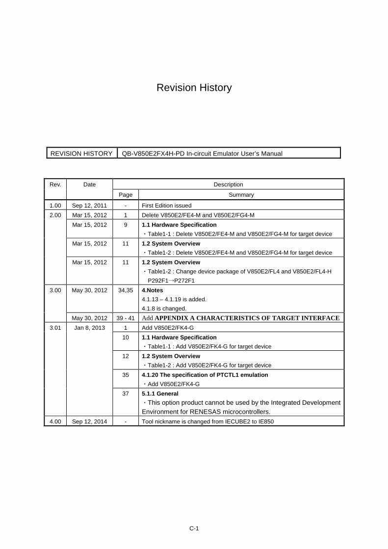
REVISION HISTORY QB-V850E2FX4H-PD In-circuit Emulator User’s Manual
Rev. Date Description
Page Summary
1.00 Sep 12, 2011 - First Edition issued 2.00 Mar 15, 2012 1 Delete V850E2/FE4-M and V850E2/FG4-M
Mar 15, 2012 9 1.1 Hardware Specification ・Table1-1 : Delete V850E2/FE4-M and V850E2/FG4-M for target device
Mar 15, 2012 11 1.2 System Overview ・Table1-2 : Delete V850E2/FE4-M and V850E2/FG4-M for target device
Mar 15, 2012 11 1.2 System Overview ・Table1-2 : Change device package of V850E2/FL4 and V850E2/FL4-H P292F1→P272F1
3.00 May 30, 2012 34,35 4.Notes 4.1.13 – 4.1.19 is added. 4.1.8 is changed.
May 30, 2012 39 - 41 Add APPENDIX A CHARACTERISTICS OF TARGET INTERFACE 3.01 Jan 8, 2013 1 Add V850E2/FK4-G
10 1.1 Hardware Specification ・Table1-1 : Add V850E2/FK4-G for target device
12 1.2 System Overview ・Table1-2 : Add V850E2/FK4-G for target device
35 4.1.20 The specification of PTCTL1 emulation ・Add V850E2/FK4-G
37 5.1.1 General ・This option product cannot be used by the Integrated Development Environment for RENESAS microcontrollers.
4.00 Sep 12, 2014 - Tool nickname is changed from IECUBE2 to IE850

QB-V850E2FX4H-PD User’s Manual Publication Date: Rev.4.00 Sep 16, 2014 Published by: Renesas Electronics Corporation

SALES OFFICES
Refer to "http://www.renesas.com/" for the latest and detailed information.
Renesas Electronics America Inc. 2801 Scott Boulevard Santa Clara, CA 95050-2549, U.S.A. Tel: +1-408-588-6000, Fax: +1-408-588-6130 Renesas Electronics Canada Limited 1101 Nicholson Road, Newmarket, Ontario L3Y 9C3, Canada Tel: +1-905-898-5441, Fax: +1-905-898-3220 Renesas Electronics Europe Limited Dukes Meadow, Millboard Road, Bourne End, Buckinghamshire, SL8 5FH, U.K Tel: +44-1628-585-100, Fax: +44-1628-585-900 Renesas Electronics Europe GmbH Arcadiastrasse 10, 40472 Düsseldorf, Germany Tel: +49-211-6503-0, Fax: +49-211-6503-1327
Renesas Electronics (China) Co., Ltd. Room 1709, Quantum Plaza, No.27 ZhiChunLu Haidian District, Beijing 100191, P.R.China Tel: +86-10-8235-1155, Fax: +86-10-8235-7679 Renesas Electronics (Shanghai) Co., Ltd. Unit 301, Tower A, Central Towers, 555 Langao Road, Putuo District, Shanghai, P. R. China 200333 Tel: +86-21-2226-0888, Fax: +86-21-2226-0999 Renesas Electronics Hong Kong Limited Unit 1601-1613, 16/F., Tower 2, Grand Century Place, 193 Prince Edward Road West, Mongkok, Kowloon, Hong Kong Tel: +852-2265-6688, Fax: +852 2886-9022/9044 Renesas Electronics Taiwan Co., Ltd. 13F, No. 363, Fu Shing North Road, Taipei 10543, Taiwan Tel: +886-2-8175-9600, Fax: +886 2-8175-9670 Renesas Electronics Singapore Pte. Ltd. 80 Bendemeer Road, Unit #06-02 Hyflux Innovation Centre, Singapore 339949 Tel: +65-6213-0200, Fax: +65-6213-0300 Renesas Electronics Malaysia Sdn.Bhd. Unit 906, Block B, Menara Amcorp, Amcorp Trade Centre, No. 18, Jln Persiaran Barat, 46050 Petaling Jaya, Selangor Darul Ehsan, Malaysia Tel: +60-3-7955-9390, Fax: +60-3-7955-9510 Renesas Electronics Korea Co., Ltd. 12F., 234 Teheran-ro, Gangnam-Ku, Seoul, 135-920, Korea Tel: +82-2-558-3737, Fax: +82-2-558-5141
http://www.renesas.com
© 2014 Renesas Electronics Corporation and Renesas Solutions Corp.
Colophon 3.0

R20UT0822EJ0400
QB-V850E2FX4H-PD