qalo’ss handbook - impala superstore 6 - introduction my name is karl frost, but i am also known...
TRANSCRIPT

QQaalloo’’ssss
HHaannddbbooookk

- 2 -
Author: Karl Frost
“QaloSS” [email protected]
Table of Contents Introduction …………………………………………….…page 5 Chapter 1 …………………………………………….………… 6
• Websites o Forums……………………………………….…. 6 o Technical………………………………….……. 6 o General (Articles, Information, etc.)…………… 6 o Clubs/Members……………………………….… 7 o Wheels & Tires………………………………..…7 o Aftermarket/OEM Part Sales……………….…....8 o Misc. Sites of Interest……………………............8
Chapter 2……………………………………………………...…9
• Impala SS/Caprice Modification, Maintenance & Repair Procedures o Cooling System………………………………....9
• Bleeding the System………....9 • Flushing the Radiator………..10 • Water Pump Replacement…..11 • Temp. Sensor Replacement…11 • Thermostat Replacement……12 • Heater Core Flush…………...12
o Beginner Modifications………………………..13 • Intake Alternatives………….13
• Home Plate Removal • First Base Removal
• Throttle Body Bypass……….18 • Red Bow Tie………………...20
o Chassis/Suspension/Body………………………21 • Lower Body Bushings Install….…21 • Coil Spring Replacement………....24

- 3 -
• Shock Replacement……………....25 • Sway Bar Replacement…………...25 • Rear Control Arms Replacement....26 • Front Control Arms Replacement…28 • Stealth Brake Bolt Modification…..28 • Buick Brace…………………….…32
o Engine/Fluids/Filters • Air Filter Replacement…………...32 • O2 Sensor Replacement……….….32 • PCV Valve Replacement…………33 • Oil Change & Light………………33 • Transmission Fluid Change………34 • Differential Fluid Change …….….35 • Fuel Filter Change…………….….36
o Exhaust • EGR Valve Replacement……..…..37 • AIR Pump Delete……………..…..37
o Electrical • Optispark Replacement ………..…40 • Spark Plug & Wire Replacement…44 • Antenna Switch……………………48 • Pass Key Fault Disable……………49 • Radar Detector ……………………50 • Tachometer Install…………………50 • Radio wiring chart…………………52 • Headlight Panel Illumination………52 • Z28 Cluster Change………………..52
o Interior • Window Sag……………………….62 • Door Panel Removal………………64 • Lower Dash Removal……………...65 • Interior Ideas………………………65
Chapter 3………………………………………………………65
• Trouble Shooting Guide o Vibration at high speeds…………………………………65 o Temperature gauge not working or acting strange……...66 o Cooling fans won’t turn on……………………………...66

- 4 -
o Fuel gauge not reading correct amount………………….66 o Hesitation, stumble, skipping, missing…………………..66 o Steering is sluggish and loose……………………………67 o Tire wear is not even………………………………….….67 o “Clunk” shift from 1st to 2nd ……………………………..67 o Pass Key Fault light ……………………………………….67 o Overheating…………………………………………….….67 o “Waterfall” noises………………………………………....68 o Heater not blowing hot air…………………………………68 o Water in Passengers side floorboard………………………68 o Blinker not Flashing or won’t Shut Off…………………...68 o Windshield Washer Light Stays On……………………….69 o That pesky “Change Oil” Light……………………………69
• Types, Brands, Sizes, etc. of Maintenance/Performance Parts o Torque Converters…………….69 o Gear Set ………………..…..….69 o Spark Plugs & Wires….….…...70 o Oils……………………….…....70 o Tires……………………….…..71 o Belts………………………..…..71 o Sway Bars……………….….….72 o Control Arms………………… 72 o Appearance Products …………..72 o Programming………………..….72 o Springs ………………………….72 o Shocks……………………….….73 o Brakes…………………………..73 o Hoods…………………………..74
Chapter 4………………………………………………………74
• Common Abbreviations …………………………………..74 o Automotive Acronyms
• VIN Decoder……………………………………………….76 • Service Intervals……………………………………….. ….79 • Impala Specifications/Capacities…………………….…….79
o How to tell the difference, is it a real SS or a clone? • DTC Diagnostic Trouble Codes……………………………80 • RPO (Regular Production Option) Codes………………….85

- 5 -

- 6 -
Introduction My name is Karl Frost, but I am also known as “QaloSS” on all three forums. I purchased my
1995 Impala SS on November 1, 1999 with 139,000 miles on her. When you purchase a high mileage car, you will need to do some repairs in the coming months. This is how it began and how I learned about the Impala SS. After I bought the car, I knew it was special and I knew there had to be more people who loved it just as much I did. Therefore, I went searching on the internet and found NAISSO. There I found the Superstore, forum, and many helpful resources. I was so happy, I found a place I belonged to and filled a void in my life (okay bare with me, I know it is melodramatic but, hey, it’s an SS!). You know when you have something nice; there will always be someone who will mess it up. I found this out shortly after I bought the car. Someone tags my side view mirror and makes it face the other direction. If this wasn’t enough, I was rear ended a few weeks later with a total of $12,000 plus in damages. No, it wasn’t totaled; only because the bent rear axle wasn’t discovered until the bodywork was finished. To keep a long story short, within the next few years, I had one more wreck, hail damage, and had a new transmission put in, any finally a pine tree totaled it on my day off in June 2003! Yes, it was a few banner years, but I never gave up and still loved the ole girl and do not regret purchasing the car.
In conclusion, I always wanted to make a reference guide for beginners and just a helpful little tool for anyone who owns a B-body. I never had enough information to go by or enough knowledge to back up my findings. Now I have learned a lot more and have plenty of hands on experience with many procedures and many more to come. If this guide helps at least one-person work their way through a repair or modification, then I will be happy. I tried to include all credits to everyone’s comments and procedures I used in this manual, but if I left anyone out or made a mistake of any kind, let me know and I will make the appropriate corrections. Please enjoy this guide and any feedback, suggestions, new procedures, corrections, problems, praises, insults, comments, criticisms, or additions that anyone would like to make, please contact me via email at [email protected]. Thanks for reading and happy cruiSSing! Always remember when doing any modifications,” To each, his own”. Forgot who started that but it is used repeatedly.
R.I.P. “Butch” 1995-2003
DISCLAIMER: The following information is meant to be a reference guide ONLY. Intended to help on any modifications or repairs by fellow B-Body owners. It was not created to be sold and should not be sold under any circumstances. If you do not think you are
capable of completing the repair/modification, then DO NOT attempt it. All credits are given and stated by the appropriate entries. The author and/or people quoted in this guide are in no way responsible for any damages or injuries caused by any of the procedures or
repairs listed in this manual. Always use the proper safety equipment while performing any car repair. If you will be underneath any vehicle, always use good quality jacks and jack stands that are comparable to the proper weight requirements.

- 7 -
Chapter 1 WEBSITES Forums: http://www.impalaclub.com/naisso/forum2002/
• Impala SS Forum http://www.impalassforum.com
• NAISSO Forum http://www.customcomputersunlimited.com/chatroom.html
• Chat room provided by Bobby Allan, “NyteTyme.” Wednesdays @ 9pm EST or 6pm PST. http://www.4adrive.com
• 4ADrive B-Body Forum http://www.gmforums.com/
• GM Forums http://www.impalaclubofsd.com/forums/
• San Diego Forum (ICSD) Technical Websites (Also see member/club websites)
http://www.impalaclub.com • NAISSO homepage, many resources.
http://impala.homeip.net/impala/home.html • Rob Cheek’s (OASIS Club) SS
homepage. Tech tips, member directory, dictionary, very useful.
http://www.theherd.com/tech_articles.html
• Tech write-ups from The Herd club out of Illinois, Wisconsin, and Indiana.
http://www.impalassforum.com/tech.htm • SS Forum tech help.
General Caprice/Impala SS Information, Articles, etc.
http://www.geocities.com/MotorCity/6577/tsb.html • Full TSB Website for 94-96 SS’s
http://impala.lc.cc.il.us/ • Scanned articles, pictures, brochure images
94-96, 2000. http://www.depanorama.net/impala/
• Peter MacHare’s scrapbook of articles.
http://www.raiden1.com • Joe Boccia’s SS website w/ FAQ, pics, and
much more. http://www.9c1.com
• Bob Lane’s webpage about B bodies. Tech, pics, part #’s, very helpful.
http://www.b-body.net/ • IGBA b body website. Excellent resource.
http://popularmechanics.com/automotive/sub_concept_gmtoys/2001/1/510_Impala_SS/ • Popular Mechanic’s write up of the 510 ci. Impala SS.

- 8 -
Impala SS Club/Members Websites http://www.theherd.com
• Illinois, Wisconsin, and Indiana area. http://www.goissca.org/
• National Impala SS club. http://www.hotss.com
• Austin, Central Texas SS Club http://www.lisst.com
• Long Island SS Club. http://www.hossimpala.com/
• HOSS club out of Texas. http://www.cusstom.com/
• “Fbiss” Contains MANY various pics. Excellent!
http://www.regionofdoom.com/default.htm • Northern Cali, Region, and Nevada
SS club. http://www.carissma.com/
• The Carolinas http://www.cttri9.com/
• Connecticut Tri-9 http://www.colpetzer.com/bisson/index.htm
• Buffalo SS Owners http://home.rochester.rr.com/raisse/
• Rochester NY http://members.cox.net/impalaclub/
• Tidewater, VA http://www.gassit.findhere.org/
• Georgia Area SS Owners http://www.sofasst.com/
• South Florida http://autos.groups.yahoo.com/group/OB_BO/
• Ontario SS Owners http://fly.hiwaay.net/~rayc/naimpala.htm
• North Alabama SS Owners http://www.taisso.com/
• Toronto area http://www.missl.org/
• Michigan B Bodies http://www.grail-ss.com/
• Missouri http://www.sail-ss.com/
• San Antonio TX http://www.socalss.org/
• Southern California
http://www.goissca.org/~indipalass/IndipalaSS_Index.htm • Indiana SS Owners
Wheels & Tires http://www.tires.com/
• Discount Tires Direct http://www.wheelsforless.com/
• Wheels for Less
- 9 -
Impala Aftermarket/OEM Part Replacement
DAL SLABAUGH [email protected]
1-877-448-5451http://www.gmpartsdirect.com/
• GM Parts Direct http://www.impalasuperstore.com
• NAISSO Impala SuperStore http://www.socalstreettrends.com/
• SoCal Street Trends http://www.bowlinggreencustoms.com/
• Bowling Green Customs http://www.rockauto.com
• Rock Auto. Good prices on AC Delco products plus images & part #’s!
http://www.summitracing.com/ • Summit Racing
http://www.jegs.com • Jeg’s
http://www.bmrfabrication.com/ • BMR Fabrication. Sway bars, control
arms, etc. http://www.pcmforless.com
• Bryan Herter programming. http://www.impalaperformance.com
• RAISS kit and parts. http://www.lmperformance.com/
• LMPerformance
http://www.suncoastcreations.com/ • Suncoast Creations
http://www.mbaproducts.com/ • Mallory Billet Aluminum Products.
http://www.rksport.com • RK Sport
http://bigfastcar.com/ • B-Body High Performance Inc.
http://www.slponline.com/ • SLP Performance Parts
http://www.autocandy.com • Ray Campbell from NASSA club’s
website. http://www.impalasscarpet.com/
• Impala SS Carpet. All carpet accessories.
http://www.clearimageautomotive.com/ • Clear Image Automotive
http://www.enginedressshop.com/ • Engine Dress Shop. Engine décor.
http://www.jetchip.com/ • Jet Performance Products
http://www.yearone.com/ • Year One
Miscellaneous Sites of Interest http://www.harborfeight.com
• Low Cost Tools http://www.pgctv.com/videos/
• Hard copy videos of Impalas. http://www.zainobros.com/
• Zaino polish. http://www.borla.com/
• Borla exhaust systems http://www.acdelco.com/
• AC Delco listing of parts. http://www.edelbrock.com/
• Edelbrock Performance http://www.eibach.com/
• Eibach Springs http://www.installdr.com/
• Radio wiring schematics for any car.
http://www.slpeng.com/ • SLP engineering
http://www.stillen.com/ • Steve Stillen Sportparts
http://www.alldata.com • All Data. TSB’s and recalls
http://www.car-stuff.com • General all around Car Stuff
http://www.metco-inc.com • Metco Motorsports Solutions. Control
arms http://www.gm.com
• General Motors website. http://www.lingenfelter.com/
• Lingenfelter Performance Engineering
- 10 -
Chapter 2
IMPALA HELP FACTS/COMMON PROBLEMS
COOLING SYSTEM Bleeding the system:
I am sure that everyone has his or her own way of doing this and this is what worked best for me. I found it easier to get the last bit of air out of the system when the car is cold. Here is my theory. While the car is running, air can be trapped and it will be hard to bleed it out. So here is what I did, start the car, get it warm, and make sure the heat is on hot. If you can park it where the rear is lower than the front would be best. Then in the morning (let the engine cool and do not start the engine), crack the bleeder screw and let the air out. I did this for two or three days to get all the air out of my system. No more waterfall sounds.
~“1996ISS”
Yes, get the bleed valve higher than the heater core, just jack up the front end. Another tip I heard of, unscrew the bleed valve and in its' place get a small ball valve and one of those barbed fittings for a rubber hose. Run the hose long enough down away from the optispark. Use the clear Tygon tubing so you can see the bubbles.
~“Douglas” That’s what I did, the "freasebleeder" mod. I got a quarter turn ball valve (1/8-27 thread) and
a barb fitting and the clear nylon hose to fit. Use a gallon jug as a catch can. Here is the tip I got from a professional (atlaSS96), run the car and get it hot, and bleed what you can.
~”uwsacf” Shut the car off and let it sit for 10 minutes, then bleed again with the engine OFF. Worked
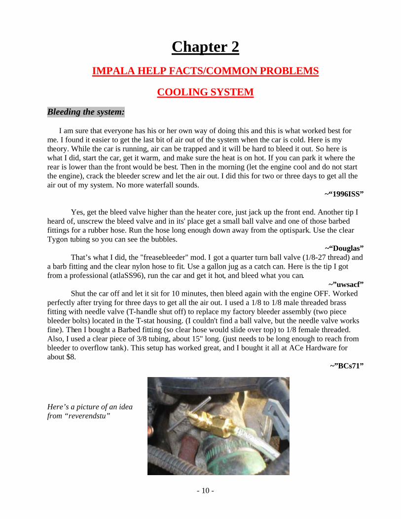
perfectly after trying for three days to get all the air out. I used a 1/8 to 1/8 male threaded brass fitting with needle valve (T-handle shut off) to replace my factory bleeder assembly (two piece bleeder bolts) located in the T-stat housing. (I couldn't find a ball valve, but the needle valve works fine). Then I bought a Barbed fitting (so clear hose would slide over top) to 1/8 female threaded. Also, I used a clear piece of 3/8 tubing, about 15" long. (just needs to be long enough to reach from bleeder to overflow tank). This setup has worked great, and I bought it all at ACe Hardware for about $8.
~”BCs71” Here’s a picture of an idea from “reverendstu”

- 11 -
Flushing the Radiator
http://www.impalassforum.com/tech/engine/coolant/coolant.htm
Here is a great way to change the anti-freeze / flush the system and not get the dreaded waterfall noise.
1. Remove the plastic junk on top of the motor. Home plate and first base.
2. Take the overflow breather off and let it drain into a bucket. This will syphon a 1/3 of the anti-freeze out of the motor.
3. Remove bottom hose to drain radiator. If you don't want to drain radiator skip to step five.
4. Put bottom hose back on and remove the top hose near the air box.
5. Move your car to a spot that you can spill some anti-freeze. Eithor push it or put the MAF back in and start it. It will only be running for a short time so nothing bad can happen. I guess you could be really smart and start the process where you can spill some anti-freeze but it was cold and windy when I did this.
6. Start car and let it push the remainder of the freeze out. Using a hose run water into the overfill container. It will suck it into the motor about as quick as the garden hose can go. Continue doing this until you see no more coolant come out. You might want to cycle the heat on to get water through the heating core. It might take a little bit for the stat to open but when it does all the old crap comes flying out. When done librally wash off all anti-freeze off the fron of your car. That stuff can't be good for the paint. IMPORTANT!!!! IF YOUR CAR IS HOT DO NOT PUMP COLD WATER INTO THE MOTOR!!! LET THE ENGINE COOL FIRST. I WILL NOT BE HELD RESPONCIBLE FOR SOMEONE CRACKING THEIR BLOCK OR HEAD BECAUSE THEY WERE IMPATIENT.
7. When all the old coolant is gone stop putting water into the overflow and let the motor pump dry. When the water starts to surge out of the hose shut her down. You still have 2 gallons in the system.
8. Put all the hoses back on tightly, and start to fill the overflow container with straight anti-freeze. Remember there is still 2 gallons of water in the motor.
9. Start motor and let it suck everything in through the overflow. When it won't take anymore and the stat has opened (top hose will be warm) open the bleader valve going into the stat. It will hiss and piss and hiss and piss for a while. I would do this 6-8 times, only letting about a 1/4 of a gallon bleed out in total.
10. Put all the plastic junk back on the top of the motor, and make sure all hoses are on and tight. Don't for get the little overflow hose.
11. Keep adding until you are at the cold fill mark and go drive for a few days. Top off some morning to the cold fill and you are done.
~Procedure by Mark Ekberg

- 12 -
Water Pump Replacement Well, the whole thing will take you a while but is fairly easy. First, you will need to drain
the cooling system, its a good idea to replace hoses if they need it since you have it flushed as well as the thermostat (may want to upgrade to a 160* one) next remove the home plate, first base and elbow to get them out of your way. Next go ahead and disconnect the hoses from the water pump. Now youre are going to have to remove your AIR pump and harness and the serpentine belt. Remove the bolts from the water pump and when it breaks from the block there will still be fluid coming out so make sure you DON’T get it on the optispark unit b/c it will mess it up, but if you have the money at 80k miles you might want to go ahead and replace it b/c if that pump was leaking on it, it may have already gotten some in it and if so you will be replacing it soon . Replacing it is the same except you have to remove the main pulley that requires a special tool. Now when you pull the pump off, pull it towards you, not down or it will damage the splined shaft behind it. Clean everything off from the old one, remove all the old gasket, and put it back on in the opposite order. Also, it would be a good time to replace the spark plug wires since everything is out of your way too. However, it’s just a thought. Good Luck man, I’ve taken that thing off twice and it gets easier every time. Some of the other guys will probably tell you some more but you can get the Haynes manual at a car parts store and it tells you everything. Just email me if you have any more questions. PS- When you get finished, sit back and enjoy a tall cold one, hell enjoy 12 of those bad boys!
~”QaloSS”
Ø Another tip, the weep hole on your water pump. Get a 1/8" NPT (National Pipe Thread) tap and run a thread in the weep hole. Then get a barbed fitting and run a short piece of tubing. If the WP goes, it won't drip on your optispark.
~“Douglas”
Temperature Sensor Replacement There are 2 different sensors. There is one on the water pump which sends readings to the PCM, and there is one in the passenger’s side manifold that sends reading to you gauge on the dash. Both sensors can be unscrewed with a crescent wrench but it is recommended that you use a deep socket. Water Pump Sensor: Simple to replace. Simply unscrew the sensor from the water pump after disconnecting the electrical connector. Have the new one ready with Teflon tape on the threads and install it when the old one is removed. Coolant will leak so have some rags or bucket handy to catch any leaking coolant. Manifold sensor: This one is more difficult and the most common cause of gauge problems. Do this when the car is cool. Raise the vehicle, and feel around the middle of the engine around the headers. The sensor is covered in a heat resistant silver coating to repel heat. Pull back the wrapping and disconnect the sensor harness. Slowly unscrew the sensor until it’s loose enough to finish it by hand. Coolant will come out of this hole pretty so you will need to be quick and do not have your face looking directly up at the sensor or you will regret it. Once you get the sensor out, quickly install the new one, wipe off any excess coolant and reconnect the sensor.
~”QaloSS”
- 13 -
Thermostat Replacement Tools:
• Socket wrench • Flat head screwdriver • Rubber mallet • Rags and bucket • Pliers • New screw driven hose clamp for larger hose • Siphon tool (not required)
There are two nuts on the top of the home plate. Remove those first, then use a screwdriver to loosen the clamp where the home plate attaches to the intake elbow right in front. Pull the home plate off and then you will need to loosen the clamp around the intake elbow where it meets the throttle body. You get the elbow and first base out of your way; you can loosen the clamp on the side of first base to disconnect it from the MAF sensor. Disconnect the hose and harness from the elbow before pulling on it.
After you have everything off, you will see the gooseneck coming out of the water pump. Your thermostat is underneath that neck. I usually release the petcock at the bottom of the driver’s side of the radiator to lower the level of coolant to prevent a lot of spillage. Not too much, just a little will do. Now remove the hose clamp from the upper radiator hose leading into the water pump (you will need pliers for the original clamp). Before you remove the hose, have some rags and/or a bucket to contain the spillage. Coolant on the optispark is bad news! Slowly pull off the hose. It may be stuck on it but a good twist will loosen it. When the hose gets loose, stick the end in the bucket or rags whichever you have handy. I stuff a rag in the end of the hose to prevent coolant from dripping out. Now for the gooseneck, you can look into the gooseneck and see coolant and the thermostat. Use rags or a siphon to get out the coolant around it. Use a wrench to loosen the bolts of the gooseneck. If the gooseneck is stuck, then tap it with a mallet to break it loose. Remove the thermostat and O-ring, and remove any old gasket material from the lip. Install the new one with a new gasket, and proceed in the reverse order. After you replace everything, replace the coolant you drained or siphoned with new coolant and bleed the system.
• This is a good time to replace any hoses that are cracked or deteriorated • Recommended to flush the radiator if it hasn’t been done recently
Note: You can replace the stock thermostat (180-degree) with an aftermarket 160-degree thermostat. It will cause the engine to run cooler but will take the heater longer to warm up in the winter. Some say there is no difference without PCM reprogramming or you must have the PCM reprogrammed. Wrong. The thermostat is not controlled by anything but temperature. If you have the PCM reprogrammed, then the 160-degree thermostat will be more effective combined with the fan temperature settings.
~”QaloSS” Heater Core Flush
If it looks like a rubber elbow approx. 1/2" ID, it's the drain for your heater box. If you have
a lot of coolant running out of it, it means your heater core is most likely shot. Don't worry, the core isn't that expensive and changing it is relatively easy. I don't know about photos. I did mine a few months ago and it wasn't difficult. Hope I remember right. You will need 1/4" drive tools to do this.

- 14 -
Remove the glove box. Remove the plastic panel under the dash. You'll see the flat bottom of the heater box held on with 7 screws 7/32" if I remember right. There are a couple close to the firewall. There is also a steel brace that goes to the bottom of the dash from the firewall. This will be in your way to remove the bottom of the heater box. When you have all the screws and the brace out, the bottom of the box will come loose. You will see the core inside. Disconnect the heater hoses on the engine compartment side of the firewall, go under the dash, remove the clips and remove the heater core. Replace in reverse. I got my core from AutoZone for about $65 I think. Not hard at all. Took me about 40 minutes or so.
~“sleepercaprice1”
BEGINNER MODIFICATIONS Intake Alternatives
Before doing any of the following procedures, be sure of exactly what you want first. There
are many options available but these are the cheapest. Some of the other, more expensive modifications are:
• R.A.I.S.S. – http://www.impalaperformance.com o Places the MAF sensor and filter directly onto the throttle body for quicker response o Encloses the filter to promote cold air o Air Force 1 option supplemented by the new Air Force II that is a shroud that directs
the airflow through the grill and over the radiator • RAMMIT Intake System
o Forced induction from underneath car • K & N Generation 2 Cold Air System
o Replaces “First Base” and encloses the cone filter to promote cold air into intake • SLP Ram Air System with Hood
o Coils the intake around to the top of the throttle body to work in conjunction with the SLP Ram Air hood.
• SLP Cold Air Intake o Much like the Gen 2 form K&N but has 2 cone filters and no heat shield
• SSRI - Super Stealth Ram Intake o Much like the R.A.I.S.S. but shroud is not as wide.
Home Plate Removal Before beginning this procedure: Purchase an elbow plug or have something to fill the hole in the elbow.
First off, the home plate is the “home plate” shaped air baffle that sits on top of the engine with “Fuel Injected V8” embossed on the top. This plate, along with the “first base” are baffles that reduce engine noise to quiet down the LT1 for the laid back folks, but some people like things loud with more power. Along with decreasing the noise, it also decreases the horsepower. Therefore, if you want an easy way to gain a few ponies, this is it. There are two nuts on top of the home plate. Remove those first, then use a screwdriver to loosen the hose clamp where the home plate attaches to the intake elbow right in front. Pull the baffle off and you will expose the engine to its full capacity. You will probably need to clean it after you complete this procedure.

- 15 -
Next, you will need to remove the rack that held the home plate on the engine. The two stems the plate sat on can be unscrewed using a wrench or a pair of pliers. Then remove the four screws that hold the rack as well as the fuel rails onto the throttle body. After you remove these screws, work the rack out of the way; be careful not to tear any wires. This may take a second or two because you will have to loosen a few wire/hose clamps but just be careful. When it is removed, reinstall the four screws back into the fuel rails. Otherwise, you will have problems later. Use zip ties to strap down any loose hoses or wires so they will not dangle onto hot parts of the engine. Now for the final piece, this will all depend on your money and taste. If you have not noticed already, there is a big hole in the elbow where the home plate once sat. You have many choices of what place in the hole. Whatever it is, it needs to be strong and not easily affected by heat. People have used many things; jar lids, hockey pucks, coasters, PVC plugs, etc. Anything with a good fit and strength will work. You can find many different choices by referring back to the website listing for aftermarket parts. There are many designs available, but some get pricey. When you get your plug, set it in the hole and tighten the hose clamp to a good seal. Viola, you are done. First Base Removal BCs71 Alternate Intake Here is my cheap alternative Air Intake system. Many have done it before me, but seem to have not taken pictures. Because many ask "how-to" pretty often, I took a few pics while doing mine recently. Materials needed: (2) PVC street 45 degree elbows, 3 inch diameter (3") of PVC straight pipe (1) Rubber coupling, 3 inch diameter (with hose clamps on either end) Also some PVC cement will be needed, along with either a can of black spray paint or black spray undercoating like I used. All pieces were bought at my local home improvement store, Home Depot, for about $8, with exception of the undercoating. The undercoating was purchased at an auto parts store for about $2. Total cost $10. Here are the basic materials as I bought them from the store. Notice how long the rubber coupling is---this is too long and needs to be cut in half to approx. three inches.
Here the pieces are cemented together, and the coupling is cut down to size (yeah my knife was dull
- 16 -
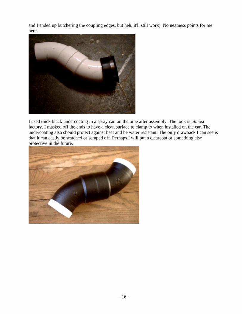
and I ended up butchering the coupling edges, but heh, it'll still work). No neatness points for me here.
I used thick black undercoating in a spray can on the pipe after assembly. The look is almost factory. I masked off the ends to have a clean surface to clamp to when installed on the car. The undercoating also should protect against heat and be water resistant. The only drawback I can see is that it can easily be sratched or scraped off. Perhaps I will put a clearcoat or something else protective in the future.

- 17 -
Installed in place of 1st base baffle, two pics.
Here is what needs to be removed to put the sewer pipe in place. This is the first base, but also pay close attention to the coupling piece at the right of the first base. This coupling clamps to the MAF and is notched on top to center the coupling. I also notched my sewer pipe coupling to ensure a good fit.
I am using the stock airbox and filter for now.

- 18 -
Many alternatives to this is to buy a K&N flat panel filter and drop in place of the stock filter, in the stock box. Many folks drill holes in the bottom of the stock airbox, which is why this method is called "swiss-cheese airbox". Another alternative is to remove the airbox completely and clamp a K&N or S&B cone filter on the opposite side of the MAF as the sewer pipe. The cost of these filters is in the neighborhood of $50. Here is thealbum in case the pics have difficulty showing up
~BCs71
Parts Required:
• A 3.5" chromed exhaust pipe cut to 13". About $20 from Pep Boys. • A 2"-3" section of 3.5" ID rubber hose. Check with a local heavy truck supply store for
Gates hoses. "GATES Green Strip 3 1/2" I.D. (89 mm)", P/N 24256, seems to work great. You can also get something called a "no hub coupler" from a hardware store. Basically, any sort of heat- resistant rubber connector will work fine. About $10 per foot.
• Two pipe clamps to secure the tubing to the MAF and the pipe. $2.
1) Originally, the pipe will come tapered on one end (the exit for the exhaust) and have a 2 1/2" "nipple" on the other to fit into the standard exhaust. You will have to cut both of these off so that it is just a straight piece of chrome pipe. If you can find such a piece without cutting, then you're better off. You'll need it to be around 13" long. The original pipe should look something like this:
________________________________ \ \____ \ | \ ____| \____________________________/
2) Loosen the clamps on both ends of the baffle. 3) Remove the baffle. You may need to remove the air filter cover to do this. Be careful not to
damage the MAF (mass airflow sensor) as you remove the baffle. While you are doing this, make sure you remember (or mark) which way the MAF faces.
4) Clamp the rubber tubing to one side of the chrome tube. 5) The other side of the rubber tubing should be clamped to the side of the MAF that originally
was connected to the rectangular baffle. The hose should fit inside the rubber coupling that used to connect to the resonator.
6) Insert the pipe into the intake elbow. Secure the clamp on the elbow so that it is tight around the pipe.
*There is some concern about putting stress on the MAF connector if you are using the stock airbox. The solution for this is to unmount the airbox from the top of the PCM and angle it such that when the straight pipe is installed, the stress on the elbow is relieved.
Procedure ( from Ted Dinsmore)
1) Take the air box lid off of the airbox base, remove the filter, and set them aside. 2) Unscrew the Torx head nut/bolt on the fenderwell.

- 19 -
3) Look at the airbox; it's actually two pieces consisting of the square airbox itself and a flat piece underneath that snaps down onto some tabs on top of the PCM.
4) Unsnap that flat piece and pull out the airbox base. 5) Take another look at the airbox after it's out of the car. You'll see two push pins holding the
flat piece to the bottom of the box -- one outside the box, one inside. 6) By *carefully* pushing the pin back through the base, remove the push pin that is outside
the box. Leave the one inside the box alone. The airbox should turn on the one remaining pin effectively providing a pivot point.
7) Snap the airbox back into place on the PCM. You should be able to turn the airbox somewhat.
8) Put the filter back in and put the lid back on the airbox. 9) Turn the airbox towards the intake elbow as far as possible without binding anything and
measure and install your pipe.
Procedure (from Erich Arndt)
http://impala.homeip.net/impala/technical/tech.cgi#intake_rect_baffle
Throttle Body Bypass
Here is the way I suggest doing the Throttle-Body Bypass on a 94+ B-body LT1 & L99. (Instructions might be a little different on a '94, and the process might also work on F-body and Corvette LT1) Supplies needed:
• Flathead screwdriver

- 20 -
• 2 pairs of pliers • door panel removal tool (less than $10 @ Autozone and will also help whenever you remove
one of your door panels) • spare rags • small clean bucket • 2 caps (rubber from hardware store or billet from AutoCandy.com) • sharp knife or scissors • 1 ziptie (optional) • a few feet of 7/16" ID rubber hose (fuel line) from a hardware store (optional)
Now would be a good time to put in a 160 deg Thermostat and flush the system. Many people recommend using regular Anti-freeze (the green stuff) instead of the Dex-Cool that General Motors suggests. If you do decide to use Dex-Cool again, DO NOT PUT IN THE CLAY TABLETS! They will most likely dirty up the coolant and might even clog your heater core. Preparation: Turn the engine off and let it cool for a while before beginning. Leave off until finished. This will help to keep you from being injured, and the coolant will not be flowing. Put the bucket below the water pump (as indicated in the picture) Put spare rags on the intake manifold (or homeplate) and stuff one under the small rubber elbow (blue) that connects the metal pipe (green) to the throttle-body. Step 1: Unscrew the screw-type hose clamp from the coolant resevoir. Remove the overflow hose and carefully lower the end into the bucket (as shown in pink). Coolant will probably begin spilling out of it. This should not last but a few moments. Reconnect the hose to the coolant tank and tighten the screw clamp. Step 2: Unscrew the screw-type hose clamp from the throttle-body side of the hose (orange). Disconnect the overflow hose, and move it to the metal pipe (green). Decide how much of the stock hose you want to trim off (just a few inches) and cut it. Remember: measure twice, cut once. You do not want the hose to hit the alternator or serpentine belt, so don't cut too much. Then reconnect the small length of hose that you cut to the throttle-body. This should keep any more coolant from falling on the water pump and Opti-spark. Let the long length of overflow hose from the coolant tank hang down out of the way. There should no longer be coolant in it, so you should not have any problems. Step 3: Using the door panel remover, disconnect the rubber elbow (blue) from the throttle-body. I found that by using the door panel remover, I didn't have to mess with the spring clamp. The hose just slid right off. There might be some coolant spilling during this, clean it up with the rag. Eventually, it should stop dripping. There might also some coolant out of the throttle-body might drip into the bucket. Step 4: Get the two pairs of pliers. Use one to rotate the rubber hose (blue) and the other to rotate the clamp until you can see the ends of the spring clips holding the tube on the long metal pipe (green) that runs from the rear of the engine to the front between the valve cover and the intake manifold. Move the spring clip inward (away from the end of the hose) by squeezing the clip with the pliers. Then slide the hose off the pipe (green). Step 5: Take the long length of overflow hose (purple) from Step 2 and attach the unconnected end (the end that you previously cut) to the metal pipe (green). Use the screw clamp from the front of

- 21 -
the throttle-body (also in Step 2) to hold it together. You might decide to use a zip tie (yellow) to attach it to the larger heater hose so it doesn't move around too much. Start the car and let it run for a few minutes to make sure everything is connected properly. Double-check all the connections and clamps. If you do not decide to switch anti-freeze, or flush the system, you will need to add some more anti-freeze to compensate for the amount that you lost. Fill the tank to the appropriate marker on the reservoir. Bleed the system as it says in the Factory Service Manual.
Procedure bv Cheston Phillips http://www.geocities.com/im_a_0/TB_bypass.html
Red Bow Tie Install Many people do not like the standard silver bow tie on the SS grill so many have chosen to go with a red one. You can buy the red bowtie a few websites but I purchased mine form the NAISSO Superstore. Lift the hood and look at the backside of the grill. There is a hole behind the original bow tie. Use a rod or screwdriver to press the old bow tie out. It is stuck in place by two sided tape so push slowly while applying back pressure to the grill for leverage and this will also keep you power freaks from cracking the grill mounts. Once you break a section loose, you can go back to the front of the grille and remove the rest with fishing line, using it like a saw, or a flathead screwdriver to pry it out. After it is out, clean the surface and remove any of the old adhesive tape. Now install your new bowtie, stand back, and enjoy.
~”QaloSS” There is also a LED bowtie, you can purchase from the Long Island SS Club http://www.lisst.com.

- 22 -
CHASSIS / SUSPENSION Lower Body Bushings I referenced Scott Mueller’s website at http://www.theherd.com/articles/bushings.html for most of this information. Read his site for more information on the reason why this mod is needed. I heard about this modification many times before I decided to do it. The one thing I found out was that I should have done it earlier! After calling Dal Slabaugh to get the parts I needed I checked
around and gathered all the information I needed to get it done. I have always been mechanically inclined but this procedure is even easy for someone is isn’t. To begin you need the proper parts. The pink bushings you will need are slightly thicker than the stock ones (Figure 1) to allow a better cushion to the frame with the exception of the Green ones (Figure 2) which fit better at Point 7.
Figure 1 Figure 2 There are 16 total points on the frame but Point 5 requires no lower bushings and the 2 under the radiator do not make much of a difference and I have been told to not mess with those due to the location of the radiator, so you will only need 12 total bushings; 10 pink, 2 green. People have mentioned the need for different bolts for position three. The stock ones are fine and you will not need new ones unless your old ones have deteriorated or rusted or you are replacing the upper bushings as well from the 9C1 package. Part Number Description Price 377801 Stock 5/8” thick soft rubber (Black) $7.16 457917 New 3/4“ thick firm rubber (Dk Green) $4.24 457915 New 7/8” thick firm rubber (Pink) $5.41 You will need 10 of the Pink ones and 2 of the Green ones. Total price should be around $ 62.58 from Dal at 1-877-448-5451. There may be somewhere else you can get them cheaper, but if not I suggest getting them from Dal
Notes:
• Points 1-3 do not have any lower bushings, only a washer and bolt. You will not need to use this washer with the new bushings.
• When installing the bushings from Points 1-4 be sure not to catch any wires or cables.

- 23 -
Tools you will need: 15 mm socket wrench w/ 6-inch extension. Torque wrench. (optional) Breaker bar or pipe to slip over you wrench to help break the bolts loose (if needed) Car jack and jack stands (optional). And of course, your bushings
• Points 4-7 (minus Point 5) will have the old bushing and bolt with no washer, simply discard the old bushing and re-install a new one.
• Points 1,2,3,4, & 6 use the pink bushings, and Point 7 uses the green ones. • All Points have a large opening in the frame
(Figure 3, right) with the exception of Point 3 that has a small hole to insert your socket wrench.(See in Procedure)
• When installing the bushings, the cupped end goes against the frame. Each bushing has a washer inside it on the flat end. The bolt head should go against it.
• Torque the bolts to 30 ft/lbs. I agree with Scott rather than the factory 50 ft/lbs.
Figure 3
• When removing the bolts, Use a breaker bar or pipe to slip over your wrench. I broke my Craftsman socket and could see the wrench bending removing mine.
• When installing the new bushings, the bushing will not sit snug against the frame. The upper bushing fits into the lower bushing with metal tube with rubber around it so there will be a small gap between the lip and the frame so don’t get mad or keep tightening the bolt thinking they will or you’ll strip the hole. Some have fixed this problem by doubling up on the bushings or using shorter bolts all around.
Procedure: 1. You will need to raise one side of the car on jack stands to allow better access to the bolts and make for an easier install. Which end you start at depends on you, but I went from Point 1 to Point 7. 2. Point 1 is directly behind the front tire at the end of the curve towards the engine. It’s hard to see the bolt but it’s there. Remove the bolt and washer and install the bolt and new pink bushing with no washer and tighten to specs. 3. Point 2 is a foot down from Point 1 right at the elbow of the frame. Remove the washer and bolt and install the bolt and new pink bushing with no washer and tighten to specs.
- 24 -
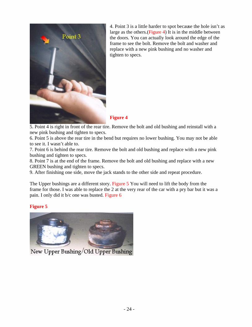
4. Point 3 is a little harder to spot because the hole isn’t as large as the others.(Figure 4) It is in the middle between the doors. You can actually look around the edge of the frame to see the bolt. Remove the bolt and washer and replace with a new pink bushing and no washer and tighten to specs. Figure 4
5. Point 4 is right in front of the rear tire. Remove the bolt and old bushing and reinstall with a new pink bushing and tighten to specs. 6. Point 5 is above the rear tire in the bend but requires no lower bushing. You may not be able to see it. I wasn’t able to. 7. Point 6 is behind the rear tire. Remove the bolt and old bushing and replace with a new pink bushing and tighten to specs. 8. Point 7 is at the end of the frame. Remove the bolt and old bushing and replace with a new GREEN bushing and tighten to specs. 9. After finishing one side, move the jack stands to the other side and repeat procedure. The Upper bushings are a different story. Figure 5 You will need to lift the body from the frame for those. I was able to replace the 2 at the very rear of the car with a pry bar but it was a pain. I only did it b/c one was busted. Figure 6 Figure 5

- 25 -
Figure 6
Coil Spring Replacement For the front, it’s a harder but the rears are easy as pie. Front You may want to bite the bullet and have someone install these for you, but if you are hard headed then go for it. You’ll need new insulators, a spring compressor and a special tool to break the joint loose on the control arm. Do these one at a time and keep your day open, it will take a while.
1. Jack up the corner you’re working on and place it on jack stands by the frame, you’ll need the jack for the spring install.
2. Remove the shock (see shock replacement procedure). 3. Remove the wheel and disconnect the lower part of the spindle and sway bar
end links. 4. Use your spring compressor to compress the spring. Now place your jack
under the control arm to brace it and remove the bolt on the ball joint. Use your special tool and break the ball joint loose.
5. Lower the control arm and remove the spring. 6. Compress your new spring and install the insulator on top & bottom. A piece
of tape will hold them on b/c without it, the insulator will get misaligned and cause squeaking later.
7. After it is in place, raise the control arm back up and reinstall in the reverse order.
The process sounds easy but it is HARD, especially while on the ground. So remember what I said about having them installed. Rear These are MUCH easier. You will need new insulators, a jack, and jack stands.
1. Raise the vehicle by the axle and place jack stands under the frame. 2. Leave the jack in place, lower the axle until it is at rest, and stop. 3. There should be enough room to simply pull the spring out by hand but if there isn’t then
remove the bottom of the shocks by unscrewing the nut on the end of the lower control arm and lowering the axle a little bit more.
4. Use a piece of tape to hold the new insulators in place while you put it back in. 5. Make sure the spring are set in the holders attached to the axle and not blocking the little
drain hole.

- 26 -
6. Reinstall the nuts on the shocks if needed and raise the vehicle back up off the jack stands. 7. Remove the stands and lower. 8. Sit back and enjoy!
Shock Replacement Replacing the shocks is easy for these cars but you may run into a snag when it comes to the upper connections. Front
1. Raise the corner you are working on and place on jack stands by the frame. 2. It is easier to do by removing the wheel but you don’t have to take it off. 3. Look at the top of the fender well and you will see the retaining nut for the shock. Remove
the nut. You may run into rust or the nut will stick. Spray with a nut loosening and continue after letting set for a few minutes. Tip:The stem it is on will usually have a pattern so you can grip it with pliers to hold it while you remove the nut.
4. Now go to the bottom and unscrew the 2 retaining nuts. The shock should slide directly out of the spring. Raise the vehicle some more if you need more clearance to get it out while on the ground.
5. Reinstall in the reverse order. Rear
1. Raise the vehicle by the axle and place jack stands under the frame. 2. Leave the jack in place, lower the axle until it is at rest, and then raise it back up just a hair. 3. If you have another set of jack stands, you can put those under the axle while doing this, but
if not a jack will do fine. 4. Remove the nuts at the bottom of the shock and slip it off the lower control arm. 5. Now, here is the tricky part. The more room you have, the better it will go. Remove the
spring (see spring removal) and the wheel if you have big arms like me. 6. Okay, the top is held by 2 bolts. Only one needs to be completely removed. The shock
bracket has 2 sides, one is a complete hole and the other is a crescent so it will slide from around the bolt. Which one is it? Only you will know.
7. Use a LONG extension to your socket wrench to reach the bolts and use a small wrench to get to the get to the top side. You will be working blindly getting on the nuts on the top but be patient and you’ll get it.
8. Reinstall in the reverse order. Usually people will turn the bolts around for the top part of the shock so it will be easier reinstalling them. Truth is, GM should have tack welded the nuts into place when they built the car. The most important thing to remember is to be patient through this process.
Sway Bar Replacement
*You can check in the preferred types for a selection of different sway bars. Front Remember to get new bushings and/or end links when replacing in order to fully optimize you new sway bar. They are around 16-20 bucks and can be purchased at Auto Zone.
1. Raise the vehicle and place jack stands under the frame. 2. Remove the end links that connect the sway bar ends to the spindle, but keep track of the
order of the bushings and washers in case you are reusing your old ones. 3. Remove the 4 bolts that attached the brackets to the frame (2 in each bracket). Be careful,
the sway bar is heavier than it looks so don’t let it fall on your face!

- 27 -
4. Reinstall in the reverse order. If you use urethane bushings, you can grease them up to lengthen their life and reduce squeaking.
Rear
1. Raise the vehicle by the axle and place jack stands under the frame. 2. The sway bar is held on by 4 bolts to the lower control arms, 2 to each side. 3. Remove the bolts and don’t let the sway bar hit you in the face! Remember, it is heavier
than it looks! 4. Reinstall in the reverse order.
When you finish, take your beast for a ride. You WILL notice a difference. Rear Control Arm Replacement
Well, the lowers are very simple and the uppers are pretty easy to remove as well, but the main thing you need to consider is the alignment of the axle. DO NOT remove all arms at the same time. Go one by one so it will be easier to reinstall the arms. You will likely have a adjustment to be done to get the bolts to line up but it wont be more than nudge to the rear tires here and there.
Before starting to replace either the upper or lower, remember to select what brand you need or if you want to remain stock, AND if you want to get extended and center the rear wheels or remain stock length. Stock arms are okay but it really makes a difference to use aftermarket arms. (See section of preferred brands). Now, choosing extended or stock length. Well, the change doesn’t help you any by performance except maybe a longer stance and slightly better handling but no one has ever said it noticeable. The main purpose is to center the rear wheels. If you haven’t noticed already, the rear wheels sit a little forward in the wells. Some don’t like this look and some don’t care. IF you decide to go with extended arms, there are other issues. One is maybe getting a new driveshaft, or you can get a longer yolk. It will work for a while if you change neither, but the seal to the transmission will grow weak and soon you will be wishing you took more time researching this procedure.
First, when you start, you will need 4 jack stands and a jack. Lift the rear of the car by the differential and chock the front wheels, then place jack stands under the frame. Lower the jack until the axle is at rest and lift back up a little and support the axle with the other 2 jack stands. It is important you support the axle in its normal position.
The lowers are a cinch. Remove the sway bar (See sway bar removal), unbolt them, and replace the arms one at a time. The uppers are the same way but the bolts connecting the arms to the body are a PITA to get to and are large, I believe they were 21 or 22mm, but don’t quote me on that! You’ll need a socket in that size as well as a wrench to hold the nut. Removing those bolts from the holes is somewhat difficult but a few whacks of a hammer or wrench and they’ll come out. If you flatten the threads, don’t worry, the new arms come with new bolts.
Now, the hardest and most time-consuming part of the replacement is the bushing removal. Follow Noel’s instructions. I personally used this procedure. The only thing I recommend is to use a sawzall. A jigsaw is worthless and be prepared to hammer a while getting the bushing back in. I recommend the Metco tool because you tend to beat the mess out of the new bushing. Also, when you use the puller to remove the shaft from the middle of the bushing, use a bolt laying around and drill an indention in the tip and let the bolt do the pushing and not the tip of the puller bolt. You

- 28 -
don’t want the place you rented it from or yours to get damaged, and the one I rented was a little thin and wanted to sink into the tube. Rear End Bushing Removal
By Noel Haro Background
This came about when installing my new set of BMR lower control arms. When, it came to the bushings, I wanted to replace them but I didn't buy the Metco tool cause I'd probably only use it once (or being the cheap bastard that I am [:-D] ). I looked around my garage to see what I had to remove them.
Read on and you'll see what I did.
Now this tip came from someone whose name escapes my mind but comes in very handy. When removing the control arms, there's no need to disconnect the brake lines and therefore, no brake bleeding.
1. Jack up the car as high as possible, chock the front wheels and put jackstands under the car. PLEASE TAKE ALL SAFETY PRECAUTIONS AS YOU WILL BE UNDER YOUR CAR FOR AWHILE.
2. Remove the bolt holding the brake line to the axle housing (at the top of the diff).
3. Open the tabs along the housing to detach the brake lines from it.
4. While lowering the axle, bend the lines down for more slack. Be careful not to put and kinks in the line. Bend it smoothly and evenly.
5. Installation is the reverse. Now to the bushing removal. Specific Tools
• Gear puller • Sawzall or Jigsaw (Sawzall is preferred) • Rubber mallet • Hammer
After you remove the control arms and lower the rear end and frame to work on it, do the following:
1. With the rear end as low as possible, put a block of wood (or similar) on both sides of the rear end to stabilize it.
2. Get a gear puller which has the center bolt approximately the same diameter of the inner metal sleeve in the bushing. You'll place the puller on the back side of the bushing (facing the rear of the

- 29 -
car) and pushing the metal sleeve towards the front of the car.
3. You'll notice that the bushing casing has an outer lip. I used a 3 prong puller and attached it there and centered the bolt on the metal sleeve. I used a ratchet to move push the sleeve out the other side. You can use an open end wrench as well.
4. Depending on the type of puller you use and how long the center bolt is, you may need some extra length to push it completely out. I used a small socket to get the "extra length" need to push the sleeve out completely.
5. Once you have the sleeve out, use a sawzall to cut a wedge out of the rubber bushing. You will only be able cut in certain areas due to things getting in your way. Alternatively, you can use a jigsaw but the blade won't be long enough to cut it all the way through. You'll have to cut it from both sides. And yes, the rubber will start to smoke and smell horrible.
6. Once there's a wedge out, cut the outer metal sleeve (facing the front of the car) through the wedge you've just cut out - cutting lengthwise from the back stopping at the axle. Make a few cuts. You can also cut the entire length of the metal housing but be careful not to cut into axle housing.
7. After you cut it, use a hammer to collapse the outer sleeve in. You don't have to completely collapse it. Just as long as the outer sleeve starts to come away from the axle housing.
8. Use a rubber mallet (anything with a big surface area) and hit it from the side facing the front of the car so the bushing flies out towards the back of the car. Trust me, it will fly. All it took was one hard hit. That's it. It took me about 1/2 hour for one side and just 10-15 minutes for the other side (after I figured it out).
I have no tips for installation of the new bushings other than starting it square with the axle housing and "working it in" by hitting it with the rubber mallet. YOU WILL GET TIRED swinging the mallet repeatedly. Keep a six pack handy.
~Noel Haro AKA impala_1995_ss on ISSF
Front Control Arm Replacement
Stealth Brake Bolt Modification Brake Combination or (Proportioning) Valve Mod
Posted by: kdrolt Senior Member Member # 776
Page Established 2/22/98
- 30 -
What is the Brake Proportioning Valve mod?
The Brake Proportioning Valve mod is a modification to the brake combination valve (combi valve) that increases the hydraulic pressure available to the rear brakes and results in less
brake dive, more even brake pad wear, and slightly firmer pedal feel.
GM installed the same brake combination valve in the Impala SS that they used in the Caprice with rear drum brakes. Because of functional differences between drum and disk brakes, cars with rear drums use a device which delays the onset of braking to the drums as well as reducing the pressure to the rear calipers. Because the Impala was made in such small numbers, GM didn't bother to design a specific proportioning valve for the SS. Thus, the Impala exhibits excessive brake dive (the nose dips) under heavy braking and the front pads wear out quickly. The rear pads last practically forever, since they are essentially just along for the ride.
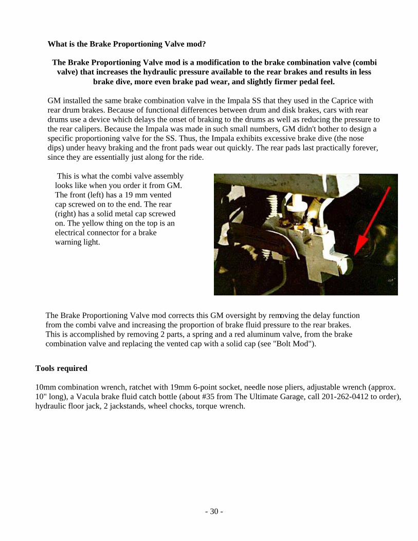
This is what the combi valve assembly
looks like when you order it from GM. The front (left) has a 19 mm vented cap screwed on to the end. The rear (right) has a solid metal cap screwed on. The yellow thing on the top is an electrical connector for a brake warning light.
The Brake Proportioning Valve mod corrects this GM oversight by removing the delay function from the combi valve and increasing the proportion of brake fluid pressure to the rear brakes. This is accomplished by removing 2 parts, a spring and a red aluminum valve, from the brake combination valve and replacing the vented cap with a solid cap (see "Bolt Mod").
Tools required
10mm combination wrench, ratchet with 19mm 6-point socket, needle nose pliers, adjustable wrench (approx. 10" long), a Vacula brake fluid catch bottle (about #35 from The Ultimate Garage, call 201-262-0412 to order), hydraulic floor jack, 2 jackstands, wheel chocks, torque wrench.

- 31 -
This shows the brake combination valve (combi valve) which is located below the brake fluid reservoir and master cylinder. The red arrow points to the 19 mm cap which has been replaced as part of the Brake Proportioning Valve modification.
Installation
• Place 4 sheets of paper towels underneath the brake combination valve to protect your car from the small amount of brake fluid which will leak out in step 6.
• Remove the rubber vented cap and paper tag from the original bolt at the front of the combination valve.
• Place the following within reach under the hood of your car: ratchet with 19mm 6-point socket, adjustable wrench, needle nose pliers, modified bolt.
• Stabilize the combi valve body with the adjustable wrench while loosening the vented bolt with the ratchet. This will prevent the brake lines which support the combi valve from becoming bent.
• Continue to loosen the vented bolt until you feel a gentle "pop". This is the spring inside the combi valve popping the bolt off. Remove the bolt and set it aside.
• Using the needle nose pliers, remove the spring and gently pull the red valve straight out of the combi valve. Check to be sure that the red valve has a small black plastic doughnut at one end. If not, you will need to fish it out of the combi valve opening with a pick (or a bent paper clip). The red valve and spring may be discarded.
• Install the new solid bolt in the combi valve in place of the one you removed in step 5. Stabilize the combi valve body with the adjustable wrench as you tighten the bolt with the ratchet.
• If you installed a "stealth" bolt, then reinstall the paper tag and rubber vent cap.
• WARNING: DO NOT DRIVE THE CAR UNTIL THE BRAKES HAVE BEEN BLED!!

- 32 -
Disclaimer: This document describes a modification to your Impala SS braking system. It assumes basic mechanical skills on the part of the reader. If you are not familiar with the techniques involved in bleeding your brakes, then do not attempt this modification without the assistance of a knowledgeable automotive technician. Done improperly, this modification can be dangerous. It will introduce air into your brake system which MUST be bled out prior to driving your car. The author and this web site assume no responsibility for any damages or injury which may result from this modification.
This is what's inside the combi valve.
The vented cap holds in a strong spring which pushes against the red aluminum proportioning valve.
The spring and proportioning valve are removed and discarded and the vented front cap is replaced with a solid cap.
Item:
If you mod the bolt on the combi valve closest to the radiator (on the rear brake hydraulic circuit), then you are doing the proportioning modification.
If you mod the bolt on the combi valve closest to the firewall (on the front brake hyd circuit), then you are doing the metering modification.
The proportioning mod removes the 90:10% front:rear proportioning needed on a civvy disc/drum car (because rear drums are self energizing once applied, so you only need a little bit of force to get them working). You need something more like 70:30% front:rear on a disc/disc car like the WX3/9C1.
The metering mod removes the delay in activating the front brakes. The metering was included by GM because the rear drums don't instantly apply until the brake shoe return springs have been stretched. You don't want the metering (delay) function once you fix the proportioning because in a hard stop, it means the front brakes WON'T come on at the same time as the rear brakes. In an easy stop, you won't ever notice the difference with or without the metering mod because the metering orifice has no effect.
BTW, the combi valve is called a combination valve because is serves the combination of three functions:
1. proportioning front to rear 2. metering the fronts 3. elec (shuttle) switch for the hydraulic failure for either the front OR the back brakes.
~ http://www.goissca.org/~gofasst/Tech_Section/Brakes/brakes.html

- 33 -
Buick Brace
This brace comes on a Buick Roadmaster but people have put it on their B-bodies to stiffen the rear portion of the frame. “…it does about the same thing a trailer hitch would as far as rigidity.”
~“Knightshade”
ENGINE / FLUIDS / FILTERS Air Filter Replacement
The air filter is located on the drivers side of the engine compartment. Remove the 2 screws holding the airbox lid in place and pull up, push down on the back side, and out to lift the lid. Pull out the filter and reinstall a new one. O2 Sensor Replacement
O2 Sensor replacement is recommended around every 100,000 miles. Although it is oaky to change them whenever you want and they may go bad anyway. They will cause bad gas mileage, sluggish performance and build up due to reading the wrong fuel/air mixture. You cannot “rejuvenate” an O2 sensor or “clean” it. They will usually go bad during a season change. For 1995 and before: You have two O2 sensors, both in front of your catalytic converters. You will need an O2 socket to remove them or a wrench. It is good to replace them while the exhaust is still a little warm and spray them with a loosening agent i.e. PB Blaster, WD40. Sometimes they’re easy, sometimes they’re not. For 1996: Since a government mandate to help with emissions, the 1996 B-bodies along with all other automobiles will have O2 sensors after the catalytic converters.
“You will have four O2 sensors since you are OBD II. Two are behind your catalytic converters and are useless except for emissions testing. If you do not have emissions testing in your state you can replace those with simulators. The other two are in front of your cats and, along with the PCM and a few other sensors control the entire fuel/air cycle of your car. You cannot replace those with anything other than real O2 sensors unless you want the car to run like crap. If you convert to OBD I you can leave out the rear O2 sensors entirely, not even simulators needed. Note: if you live in a state with emissions testing you will still have problems, as many states are moving to plugging into your PCM for 96 and newer cars and you'll fail if you have the OBD I conversion.”
~“Knightshade”

- 34 -
PCV Valve Replacement The PCV valve, or Positive Crankcase Ventilation valve, is located on the driver’s side of the throttle body between the #3 and #5 fuel injectors (the ones in the middle). Many people tend to forget about this small valve, and are recommended to change it every 12 months to 12, 000 miles.
The PCV (positive crankcase ventilation) Valve and Breather Element work together within the car’s emissions and ventilation systems. They serve as part of the emissions control system by re-circulating unburned gases and fumes back through the intake manifold to be re-burned. Therefore, these gases and vapors are not expelled through the exhaust system so air pollution is reduced
Benefits of changing the PCV Valve:
• Loss of power, oil dilution and even engine failure are avoided • Oil life is extended and engine lubrication is improved • Oil consumption, rough idle and air filter contamination are avoided • Environmental pollution is reduced
Oil Change
Ah, the old oil change. Well, if you don’t know how to do this, then you’re not a very mechanically inclined person and you may want to stick to labor charges. Jack the vehicle up, remove the oil fill cap, remove the drain plug and let it empty. Then remove the filter with a oil filter wrench. Use some of the old oil to lube the new filter seal.Go ahead and pour some fresh oil into the filter, this will help the engine regain oil pressure when cranking and not have to let it fill it up when you finish. Screw the filter on by hand and tighten a little, there’s no need to wrench the sucker on, just make sure it’s snug and not moving. After the filter is reinstalled and drain plug is in, lower the car and fill it up with new oil. Go ahead and put 4 quarts in and then check and add till you get in the crosshairs. Start the vehicle and let the oil flow for a few minutes. Doublecheck the oil level and you’re done. Take your used oil to a auto parts store and not your backyard! Now reset your Change Oil light. It depends in the year how this is done….
There are two methods depending on the year. One is to turn on the key "do not start the
motor" press the gas pedal to the floor three times and hold it until the change oil light flashes and goes out. The other method used on the 94s is a button inside the fuse box panel on the side of the dash. Turn key on, hold button until change oil flashes and goes out.
~“RJI”
*****You can go to the Recommended Brands Section to determine your oil.*****

- 35 -
Transmission Fluid Change
Here is a fluid many people don’t remember to change. Rule of thumb is replacing around every 15-30,000 miles. Okay, here’s the deal, I’m not a transmission mechanic but the guys who rebuilt my transmission, AAMCO, told me about this. This is a good AAMCO, some aren’t, but AAMCO, after all, is just a name; they don’t have anything to do with transmissions. The owners make a good name.
Check the fluid while the car is running and at normal operating temperature. Make sure the fluid is pink/red and does not smell burnt. Even though the fluid is pink or red, does not mean that it is still good and this is where many people make the mistake of not changing it. It loses its viscosity and detergents over time and wears your transmission out. It will slowly deteriorate your clutch discs away, you will see the particles in the fluid, causing your transmission to slip. It this condition goes unnoticed for a prolonged period, changing it would NOT be a wise decision. Many people have their own theories about this and have a story of a car that had 300k miles on the same transmission fluid and after they changed it, everything was fine. This very well may be true, but you will hear more bad stories about this than good. Why else would transmission shops not change your fluid if they offer a guarantee? Such as AAMCO, they offer a guarantee that if they change your old transmission fluid, and then it croaks, they will fix it at no charge, BUT if they don’t think it’s a good idea, as in my situation, they won’t. They looked at mine and said, “I don’t think so, but in about 6,000 miles, come see me.” Little did I know that I would be back in 6k miles slipping in overdrive. A lot of quick oil change franchises will not change it depending on the condition because they know about failure and have seen it happen. So if you’re in doubt, ask a professional, many places offer 50-60 inspections and if it checks out then they’ll guarantee it. If not, start saving your money now and think T-56 manual replacement☺.
You’ll need:
• Socket wrench • Wide collection pan for fluid • Rags • Flat head screwdriver • New filter and gasket • Maybe some gasket seal
1. Pull out the transmission dipstick about 6 inches to relieve pressure. Then
raise the vehicle just as you would for an oil change. Support it and locate the transmission pan, you can’t miss it; it’s big, square and right in your face.
2. Begin loosening the bolts around the edge of the transmission pan, but go in a criss-crossed pattern, loosening a little at a time. The pan is under pressure and you don’t want to warp it in any way. Fluid will begin to seep out of the edges but don’t worry, there’s a lot more where that came from ☺.
3. After loosening the bolts a little, place your container under the pan and center it under a corner.
4. Now loosen the bolts more at that corner and use your flathead, gently, to pry the edge down and break the seal. You can loosen the remaining corners to allow it to drain more but it gets messier the more you loosen.

- 36 -
5. After the drain has become a trickle or you spilt it all over yourself, remove all the bolts and drop the pan.
6. Take that pan and clean it, NO CLEANERS, just use a clean lint free rag to wipe it off and clean the magnet thoroughly. The magnet collects loose debris and shavings so don’t pick it off with your bare finger or you’ll get metal splinters. Don’t believe me? Try it.
7. Clean off all of the old gasket from the pan and the surface of the tranny. 8. Now to remove the old filter. Be easy on it, just twist it a little to break it
loose and wiggle it as you pull down gently. Now insert the new filter into the same hole.
9. Placing the gasket on can be a pain b/c it likes to move around and probably is deformed from being in the box. Some people use little stems that hold it in place by the boltholes or it will stay in place if you use a sealant. I usually stuck it to the pan and used a few bolts to hold it until I got it into place.
10. After you get a few bolts started, insert the rest to be sure you have everything lined up and the gasket isn’t wrinkled or out of place.
11. Tighten the bolts to specs and don’t tighten the hell out of them. The gasket will begin to squeeze out of the sides.
12. Pour about 4 quarts of fluid in the transmission. Lower the vehicle and crank it up. Move the shift lever through all of the gears a few times and let the run warm up.
13. Check the fluid while the car is running and slowly add fluid until the right level is obtained.
Differential Fluid Change I would recommend agains Synthetic lube with a posi, too slippery to allow posi to work right. Even the most diehard synthetic users on the other forum have switched back to regular because of this. Check the option tag in the trunk, if it says G80 you have posi use quality gearlube but not synthetic and use the limited slip additive. If you don't have posi just use the lube of your choice synthetic is ok.
~96CapriceMGR You can do this one of two ways:
1. Siphon the fluid out by the filler hole 2. Remove the cover w/ gasket replacement
Removing the Cover Technique: Needed:
• Differential oil 85W90 - Synthetic for no positive traction & conventional for positive traction
• New Felpro Gasket • GM Slip Additive –Avail. From dealer for about $8
1. Lift the car up on jack stands and chock the front wheels 2. Have a pan underneath the cover to catch the fluid, loosen the bolts by alternating the sides to prevent warpage of the cover. 3. When all the bolts are somewhat loose, pry an edge up and allow the fluid to drain.

- 37 -
4. Then remove the bolts and remove the cover. 5. Check to see what kind of gunk is at the bottom of the casing and inspect for any damaged parts. 6. Remove any old gasket from the cover and housing and re-install them both gradually tightening bolts to torque specs. 7. Remove the filler hole cap and fill the differential with the recommended oil and add the GM Slip Additive to the oil or you may overfill it. 8. Replace the fill hole cover and you’re done.
Using the Fillhope Technique: Needed:
• Differential oil 85W90 - Synthetic for no posi & conventional for posi • Hand pump or siphoning tool • GM Slip Additive –Avail. From dealer for about $8
1. Lift the car up on jack stands and chock the front wheels 2. Remove the fill hole cover and insert the siphon tube and remove all the old fluid. 3. Fill the differential with the recommended oil and add the GM Slip Additive to the oil or you may overfill it. 4. Replace the fill hole cover and you’re done. Fuel Filter Change
The fuel filter needs to be changed every 15-20,000 miles under extreme driving conditions. If you’re hauling aSS like I was, then follow that interval.
1. First, you need to raise the vehicle where the driver’s rear wheel is off the ground, the filter
is located under the body in front of that wheel. 2. Relieve the pressure form the system. You can remove the gas cap to do this but it’s best to
unplug the fuel pump by the wiring harness directly under the body below the tank fill tube while the car is running and let it stop. It will take a second or you can give it a little gas to until it chokes.
3. With the gas cap off, remove the bolts to the harness holding the filter in place. 4. Then use a set of pliers and a flathead screwdriver to unhook the hoses from each end. This
is a little tricky, but give a good look to them and you’ll see how they come off. Remember: There is still gas in the lines and it will pour out, so have a pan handy and then keep it there until the gas runs out. It helps to tilt it and remove the leftover gas in the filter.
5. Reinstall the new one in the reverse order making sure it is in the right direction and the hose are secure to the filter.
6. Reconnect the harness if you chose to disconnect it and crank the car. Turn the key to the “Run” position and let the pump prime the lines before cranking.

- 38 -
EXHAUST EGR Valve Replacement
One of the common repairs to the B-body LT1. It will cause hesitation, stumble, and hurt gas mileage. It’s an easy fix but a little pricey and annoying.
Get a new one or get the 6-speed EGR valve from the F-Body LT1. They tend to last longer and are the same price anyway. So buy it. Go ahead and get the solenoid as well, they’re not that much and it’s good to replace it while you’re back there. 1. The valve and solenoid are located on the back of the engine on the driver’s side. The valve looks like the one to the right. 2. It is held on by two bolts and connecting by hoses to the solenoid. The solenoid is connected by bracket to the engine that is secured a bolt. 3. Be sure to make note of how the hoses are connected while removing it. 4. Remove the old gasket from the valve and engine, and replace it with the new one and install in the reverse order. EGR Campaign Letter: If you have a 1996 with less than 100,000 miles on it and fewer than 10 years old, you may be eligible for a free replacement. Read the campaign letter at this link:
http://www.impalaclub.com/naisso/egr.pdf AIR Pump Delete Note: 1996 must be reprogrammed It will also blow your hood light, they work off the same fuse. I also believe it will give you knock on cold starts as well.
~“QaloSS”
GM TSB for Air Pump Removal- http://www.impalassforum.com/tech/engine/air_pump/air_pump.htm
Technical - Water in AIR Pump and/or DTC P0410, P0412, P0415, P0416, P0100, P0101, P0102 or DTC 48 (AIR System Disable Procedure) #01-06-04-011 Water in AIR Pump and/or DTC P0410, P0412, P0415, P0416, P0100, P0101, P0102 or DTC 48 (AIR System Disable Procedure)
1995-1996 Buick Roadmaster

- 39 -
1995-1996 Cadillac Fleetwood
1995-1996 Chevrolet Caprice, Impala SS
with 4.3L or 5.7L Engine (VINs W, P -- RPOs L99, LT1)
Condition
• Some customers may comment of a hesitation during heavy/full throttle acceleration. • A 1996 vehicle may also set any of the following DTCs:
o P0410 o P0412 o P1415 o P1416 o P0100 o P0101 o P0102
• A 1995 vehicle may set a DTC 48. • There will also be evidence of water in the AIR pump.
Cause
Under high engine speed and load conditions, hot exhaust gasses may leak past the air check valves. As the exhaust gasses in the air tube cool, water vapors collect into the AIR pump. As the vehicle is driven, condensation from the AIR pump may come into contact with the Mass Airflow Sensor through the AIR inlet hose. This condition may cause a hesitation on acceleration and may also set the DTCs.
Correction
To correct this condition, a Secondary AIR Injection Pump disable procedure has been developed. (It has been determined that the Secondary AIR Injection system is not required to meet emission requirements for these vehicles only.)

- 40 -
1. Locate the relay center (1) and air cleaner box (2).
2. Remove the AIR hose and clamp (1) from the air cleaner box. 3. Insert the plug (2) into the air cleaner box AIR hose inlet (3). 4. Install the AIR hose and clamp (1) to the air cleaner box.
5. Remove the cover (1) from the relay center (3). 6. Remove AIR pump relay (2) from the relay center (3). 7. Install the relay cover (1).
8. Install new emission label to radiator support (3). 9. Update vehicle calibration. (1995 4.3 L L99 Caprice, and 1996 vehicles)
Parts Information
Part Number Description Qty
12569122 AIR Inlet Hose Plug 1
12569123 New Emission Label 1
Parts are currently available from GMSPO.

- 41 -
Calibration Information
The Calibrations are electronic calibrations and are NOT available from GMSPO. Calibrations will be available from Techline starting February 2001, on the TIS 2000 version TIS 2.0/2001 data update or later.
Warranty Information For vehicles repaired under warranty, use:
Labor Operation Description Labor Time
J6930 AIR Disable Procedure 0.2 hr. This is a unique labor operation number for use only with this bulletin. This number will not be published in the Labor Time Guide.
1995 4.3 L (RPO L99) Caprice and 1996 vehicles should also use this add time for reprogramming:
Labor Operation Description Labor Time
J6355 Powertrain Controller -- Reprogram -- On Car Use Published Labor Times
© Copyright General Motors Corporation. All Rights Reserved.
ELECTRICAL Optispark installation Note: When replacing the optispark, add the weep hole fitting from p. 11 by “Douglas”
Complete vented Optispark Replacement Guide By John Reed
Way back in early '94 when I first picked up my Impala SS I was fairly disappointed when I opened the hood. You see I had read that the Impala engine compartment was supposed to contain one of the most powerful small block Chevy engines ever, the LT1. Unfortunately it did not look like an LT1, at least not like the one in the Corvette.
? 1992 - 1996 LT1/LT4 Corvettes (Y-Body) ? 1993 - 1997 LT1/LT4 Camaro's, Trans Ams (F-Body) ? 1994 - 1996 Fleetwood (D-Body) ? 1994 - 1996 Impala, Caprice, Roadmaster (B-Body)
After studying both the Corvette and the Impala engine bays, I determined that the dramatically different appearance between these two nearly identical engines was limited mainly to the dress items attached to the top of the respective engines. After studying both the 'vette and Impala parts catalogs I determined that it would be very easy to duplicate the look of the Corvette LT1 in the Impala by first removing the "home plate" induction resonator and it's bracketry, and then installing

- 42 -
the fuel injector rail covers and valve covers from the Corvette. This was surprisingly easy, and so dramatically changed the look of the engine, other Impala owners thought I had changed the engine itself!
Although these items can very easily be installed, there are a few modifications and adjustments that must be made, and several different parts are necessary to complete the job. The major appearance change comes from adding the Corvette fuel injector rail covers, and you can optionally also install the plastic Corvette valve covers as well. Since the valve covers are a direct bolt-on, there are no instructions necessary for them, other than what is already contained in the service manual. This text will focus on installing the fuel injector rail covers, which are a little more complicated. Finally, from 1992 - 1994 the Optispark was what is known in the gearhead world as "unvented". The reason it is called this is because it does not have the vacuum hoses connected like the newer 1995+ LT1/LT4 engines have. What the vacuum hoses do, is they pull the moisture out of the Optispark. What a lot of people don't realize is the unvented Optisparks are actually vented!! Yes, they have 3 weep holes at the base of the Optispark to allow moisture to escape. Well, all this does is pull moisture back in. Put cold water on a hot Optispark, it's going to suck the water in! This is the BIGGEST problem with the design. Before you go out and buy a brand new 1995+ Optispark, be forewarned. You CANNOT bolt a 1995+ Optispark up to a 1992-1994 LT1. The CAM is different. You could change the CAM, timing cover, CAM gear, etc but this gets expensive, and is very labor intensive. So, what is the solution? You can do 1 of 2 things : 1. Change the Optispark out and be up and running again. However you risk damaging it again. There have been people who have had to replace a brand new Optispark because they got them wet. 2. Change the Optispark out with a modified unit. The conversion process is simple! Buy a older style Optispark (the one you're supposed to buy), and simply change the cap! Of course you will need to do a few additional things.
First let's start with the parts list:
GM Parts needed:
? Optispark for 1992-1994 LT1's PN - 10457702 ? Cap and Rotor kit PN - 10457735 or ? 1995+ Distr. rebuild kit (Pep Boys or NAPA) ? 1996 Vacuum Hose Kit PN - 12556174 or ? 1995 Vacuum Hose Kit PN - 12555323

- 43 -
Order GM parts from http://www.gmpartsdirect.com/ or from your local GM dealer (yuk!). Other Parts:
? Inverse Torx Bit - E4, deep well!! SnapOn part number STLE40 - I stopped a truck, or you can order online at http://www.snapon.com/ ? 2-claw puller - Autozone ? 2 water pump gaskets ? Gasket Sealant ? Vacuum T or a brass T that will screw into the manifold ? Long Breaker bar, or torque wrench ? Brass fitting for the base of the Optispark. I got mine from the local parts house that carries various hose/pipe fittings. ? 3/16" Drill Bit (slightly bigger than the hole your drilling out) ? Bandages Recommended :
? Plugs and Plugwires Converting the new Optispark Remove your cap from your new Optispark. Nothing like taking apart something brand new eh? Remove the rotor from the Optispark. This is a torx T15 I believe. Carefully remove the rotor, and the metal disc. Do NOT remove the slotted one! It's spot welded on for a reason. Only the disc directly behind the rotor should be removed. Remove the middle spacer. This is the center portion of the Optispark body. Set aside everything, but the back plate. BE careful when handling this. Try not to get any grease, dirt or anything on the disc. You will notice 3 holes on the base. Fill the center one, and the one closest to the long pointed portion of the base in with JB Weld or something similar. I drilled out the remaining hole. Try not to get the metal shavings in or on the Optispark. Next I tapped in a brass fitting. Do not use the center hole for this, as it won't clear the balancer hub. IF you can find a brass L fitting, this would be your best bet. I wasn't able to find one small enough, so I used a straight brass fitting from a local parts house. Vacuum the metal shavings from the previous step. MAKE sure it's clean before you put it back together. Reassembly is the same. MAKE SURE you don't forget to put the metal disc back in place. If you leave it out, the gap for the rotor and cap will be WAY off. The rotor and disc are keyed, but still make sure you put them in correctly. Remove the old RTV Sealant, and put some new RTV on the cap at the electrical connection. Put it back together with the newer style cap. Lightly blow into one of the hose connections while closing off the other. You should hear no hissing. You aren't supposed to turn the shaft on the Optispark (why I don't know), but I would still recommend slightly turning it (1/4 turn is enough) to make sure everything spins smoothly. The Nitty Gritty First disconnect your battery. Drain your coolant. Be sure to open the bleed screws. This will help it drain much quicker. Remove the rubber intake elbow. Remove the upper radiator hoses.
- 44 -
Disconnect the bottom radiator hose from the water pump. Remove the coil wire, and the electrical connections from the Optispark and water pump. Pull the belt tensioner out of the way, and loosen the accessory belt. Remove the water pump. There are 6 bolts holding it in place. Additional coolant will dump out when you remove the drivers side lower bolt. Clean the old gasket material and set the water pump aside for now. You MIGHT need to remove the coil, but I didn't need to. Check the weep hole on the water pump to make sure it's not damp. This is the fun part (for me at least). Remove the 3 bolts from the balancer. The Haynes manual says you can simply pull it off without a puller. I was not able to. I had to use a 2-clawed puller. I got mine at Autozone. I believe the one I got was the 6". Somebody is borrowing it as we speak for this repair! MAKE SURE you make a note of the position of the balancer in relation to the hub. Both the hub and balancer should be marked, but not keyed. Remove the remaining plug wires. If they are old, you may want to replace them. Now is the time to do it! Remove the 3 bolts that hold the Optispark in place. Pull it straight out. There is a shaft that connects the Optispark to the Cam gear. This may or may not come out with the Optispark. At this point, you should look at the old Optispark and make a mark of where the notch (spline) is. This will assist you later. This would be a good time to put some gasket sealant on one side of the gaskets, and place them on the water pump so they can dry. This will make reinstalling the water pump much easier. With the old Optispark to compare, rotate the shaft on the new one until they match up. I found it easier to insert the shaft on the cam shaft, and then sliding the Optispark on top of it. IF there is any gap on any of the 3 mounting screws, you probably haven't lined the Optispark up correctly with the spline on the shaft. It should slide all the way on with no gaps on any of the mounting areas. Tighten the bolts, but do not over tighten. Run your vacuum lines. The clip goes on the alternator bracket. MAKE SURE the hoses are going to clear the belt. The hose that has the filter and regulator is the vacuum supply. Poke a hole in the rubber bellow (on the top) and push the L into it. Put a T or something similar on the drivers side intake manifold, and hook the vacuum hose up. Reconnect the plug wires. Reinstall the 3 bolts on the balancer. Tighten the bolts to 60 Ft-lbs. Make sure you line it up properly (see step above where you removed it) Put gasket sealant on the remaining gasket material, and reinstall the water pump. Tighten to 30 Ft-lbs. Reinstall the belt. It is much easier to do it now before you do the next step! Reconnect all the hoses, the coil wire and the other misc electrical connections (temp sensor, Optispark connector, etc). Lightly tighten the bleed screws. Refill the cooling system until it is full. Place a rag around the bleed screws, and bleed off the excess air. Don't let any coolant get on your new Optispark! Check and recheck everything. Fire it up. If everything looks good, your done! You should also pull the hose out of the bellow, and check for vacuum. If it gets clogged, or a hose gets pinched, it will cause the cap to cave in, and burn up the rotor.
~http://www.fierolt1.com/lt1_95_up_OptiReplace.htm

- 45 -
Spark plugs Installation / Spark Plug wire Replacement
PLUG AND WIRE CHANGE ON THE 94-96 GM B-BODY Pictures~ http://www.regionofdoom.com/images/doomtech/plugs/plugs1.htm
Supplies Needed
• Good set of plug wires. I and many others have had good luck with the Taylor 8mm wires from Summit Racing or other sources for approx $50 for the set. They are quality wires, fit well, available in a variety of colors, fit into the stock wire looms, and look great!
• 8 plugs : I most recently used Autolite Platinum AR106s, others have had good luck with NGK TR55s, stock 96 AC Delco plugs (use the 96 plugs, they are double platinum vs the 94-95 plugs which are single platinum), and other plugs.
• Anti-seize compound : to put on the plug threads so that you can remove the plugs on your next change
• Dielectric grease : helps seal the plug boots to moisture, a sufficient packet comes with the Taylor wires (and maybe others?) in the box.
Tools Needed
• Floorjack • 2 quality jackstands • Lug wrench, locking lugnut socket, and anything else you normally use to R-n-R your
wheels • Flathead screwdriver • 3/8" drive ratchet • several 3/8" extensions, I'd recommend them in 4",6", 12", and 18" • "regular" 5/8" plug socket, only necessary if you have headers • 3/4" open-end wrench (or whatever size appropriate for the above socket) • "U-joint" 5//8" plug socket, 3/8" drive • Set of metric 3/8" drive sockets, preferably deep well • 3/8" U-joint • Wire cutters • Needlenose pliers • Dremel Tool with cutoff wheel (only if you have headers) • A couple 3-4 foot lengths of 12-14 gauge insulated wire • Flashlight with GOOD batteries • Masking Tape • Ink Pen
Initial Directions
• Remove centercaps, loosen front wheel lugnuts • Set E-brake TIGHT. Putting "chocks" under the rear wheels would be a good idea as well. • Using jack, put the front of the car on jackstands and remove the wheels. • Be sure you pre-gap the plugs (stock is 0.050", that may change if you have an aftermarket
ignition, are running giggle gas, or have a severely modified motor). Also, put a thin layer

- 46 -
of anti-sieze on the plugs before install.....this will keep the threads from siezing to the head, and make later removal MUCH easier.
• FYI, the plugs are numbered 1,3,5,7 (from front to back) on the driver's side, and 2,4,6,8 (from front to back) on the passenger side.
Plug Directions (stock manifolds)
• ALL EIGHT plugs are accessible thru the wheelwells. No one believes me till they try this.....then they won't do it any other way!
• Starting on the driver's side, working back (plug 1), simply unplug the plug wires and use the 3/8" ratchet, a couple of the long extensions, and the u-joint plug socket to remove and replace the first plug. Go THRU the wheelwells.
• Continue this, working from front to back. Once done with driver's side, repeat on passenger side
• I'll once again emphasize : ALL EIGHT PLUGS are easily accessible thru the wheelwells with stock manifolds!
Plug Directions (headers)
• Note that I have the Clear Image Automotive Tri-Y Headers, so the info will be somewhat specific to them. But, similar will apply to other headers
• For plugs 1 and 3, it is easiest to just do them from up above. These plugs are possibly EASIER with headers than with stock manifolds!
• Plug 5 is a bit of a bear. To do it, you need to take the "regular" sparkplug socket and modify it (with dremel tool and cutoff wheel, hacksaw, or however else you wanna do it), cutting approx 3/4" off the end of the socket. This will let it JUST clear the header tube (the socket, unmodified, will NOT clear the header tube). You will also need to remove the rubber "tubing" inside the plug socket, and shorten it about the same amount (use wire cutters or something else appropriate here). Once modified, you can then slip the modified socket onto the plug and use the 3/4" box-end wrench to turn the socket and loosen it. Once "broken loose" a little, you can complete removal by hand. To reinstall, start the plug by hand and once it is "hand tight" you can slip the modified plug socket back on the plug and go from there.
• Plug 7 is the same as with stock manifolds (thru the wheel well). • Plugs 2,4,6 are easiest thru the wheel wells, same as stock manifolds • Plug 8 is another bear. Once again, put on the modified plug socket. Then, from UNDER
the car, slip the 3/4" box end wrench up and on the plug socket and loosen it up. With the headers, there will be enough room between the header collector and the engine block to get your hand with a wrench up there. Install the new plug similar to #5 (by hand, then tighten with the socket and wrench).
Wires (should work for both stock manifolds or headers)
• Before starting, note which wire loom is on which wire, and also note the order of the wires into the optispark. If you forget, the plug wire numbers ARE embossed on the optispark, next to the wire connection points. This info is also in the FSM and even in (somewhat cheaper, although often lacking) the Haynes manual.

- 47 -
• Remove the accessory belt (13mm wrench on the idler pulley), and then remove the idler pulley assembly (helps on the passenger side wires) which is held in by two 10mm bolts.
• Lay out your new plug wire set, and "prep" it by putting dielectric grease (a thin coat) in the inside of the boots on both the plug and distributor sides of the wires. Note that at least the Taylor Wire set includes TWO coil wires (one for 94-95, one for 96) so there will be an unused coil wire.
• To figure out which wire goes to which plug is simple. For the Taylors, the distributor end boots are black while the plug end boots are the same color as the wires. The "straight" distributor-end boots are for the driver's side wires (plugs 1,3,5,7) and the "bent" ones are for the passenger side wires (2,4,6,8). Then, amongst the straight-end wires it is simply 1,3,5,7 from shortest to longest, and similar amongst the passenger side wires (2 is shortest, 8 is longest).
• Unplug all 8 plug wires from the sparkplugs, unless you just changed plugs and them wire ends are already unplugged of course (grin)
• Start on the driver's side. Use a screwdriver and needlenose pliers (and just some brute force) to pop open the 4-wire holder that is a couple inches away from the optispark. This will be done from under the car. Remove the 4 wires from the holder.
• Remove the #1 plug wire from the optispark, and remove it from the car. • Unplug the rest of the driver's side wires from the optispark. • For the rest of the driver's side plugs, I found it easiest to just remove the entire metal
bracket that holds the wires (little holders, plus holds the #7 wire tight against the block) against the engine block. It is held on by two 10mm (I think) bolts, and at least with my car with the headers I could get to both bolts thru the wheelwell with some socket extensions and u-joint.
• Loosen the two bolts above, and remove the bracket from the car. It has JUST enough room to slide out the front, past the AIR pump.
• Once the bracket is removed, it is a LOT easier to individually remove/replace the wires from the bracket. Just match up the wires, and get them back into the bracket with approx the same lengths on each side of the 3 and 2 wire holders as the stock wires had. Also swap over any wire look from the old wires to the new wires, or replace with appropriate length/diameter of new loom.
• Reinstall the bracket assembly, with the 3,5,7 plug wires installed in it. Reinstall the two 10mm bolts that hold the bracket to the block.
• Plug the #3,5,7, wire boots onto the plugs, feeling for a "snap" that confirms the wire boot is tight on the plug.
• Reinstall the #1 plug wire onto the plug, and route the other end of the wire down with the 3,5,7 wires to the 4-wire holder.
• Reinstall the wires into the 4-wire holder, and snap it tight. Reinstall rest of the loom pieces (or new ones) onto the wires.
• Plug the wires onto the appropriate places on the optispark (once again, plug wire numbers are embossed on the end of the optispark).
• Now to the "fun" side (grin). Slide over to the passenger side, and unplug the wire boots from the optispark. It works a LOT better if you start with the "top" one (wire 4) and work your way down to the bottom (wire 2).
• Cut the opti-end boots off the plug wires. Trust me on this one! • Working from the motor side (mostly thru the wheelwell, some underneath), pull the old
wires out from the plug ends. This is a LOT easier than ANY other way on these wires. • Collect all the pieces or wire loom that fell off the wires as you removed them in the above
step.
- 48 -
• With the wires NOT in them, it is MUCH easier to unsnap the wire holders. Unsnap the 4-wire holder (near the distributor), 2 wire holder that held wires 6,8 (approx below the #4 plug), and the 1 wire holder that held wire 8 (approx below plug 6).
• For the 4 passenger side wires, LABEL the opti boot ends! I used masking tape, with the wire/plug number written on it.
• On the passenger side, the easiest way to route the plug wires into place is to tie the 12 gauge wire (see the "tools" section) around the plug boot end of the wire, and route the 12 gauge wire up thru the space between the accessory bracket and the AC compressor where the plug wires are squeezed thru. You can much more easily push this "stiff" wire up thru the spaces than the "limp" sparkplug wires.
• Start with the #8 wire, tie the 12 gauge wire to it and push it up and thru. Eventually, the 12 gauge wire will pop out near the #6 plug (can be seen from underneath) and you can use the wire to pull the plug wire thru to the #8 plug. Untie the #8 wire from the 12 gauge wire, and snap the boot onto the #8 plug. Then, put a piece of loom onto the #8 wire (with the loom between the plug boot and the 1-wire holder), and snap it into the 1-wire holder below the #6 plug. Making sure there is a LITTLE (but not much) slack in the #8 wire, snap the 1-wire holder closed. BE SURE you have things right, as it is a BITCH to get this 1-wire holder back open if there is a wire in it!
• Also put the #8 wire into the 2-wire holder, but DO NOT snap it shut yet! • Next, route the #6 wire up and thru with the 12 gauge wire, similar to how you did the #8.
Snap the #6 boot onto the plug, and put it (with a little, but not much) slack into the 2-wire holder. Once you are SURE that things are right, go ahead and snap shut the 2-wire holder.
• Put a piece of loom on each of the #8 and #6 wires forward of the 2-wire holder (i.e. on the parts of #8 and #6 wires that are running below the #4 and 2 plugs).
• For the #4 wire, you wanna tie a piece of 12 gauge wire to BOTH ends of the plug wire. Route the plug boot end up as you did with #6 and #8, but you'll probably have to "overshoot" to get the boot far enough down to untie the 12 gauge wire. Thus you have the 12 gauge wire on the other end to "pull it back thru" towards the optispark. Snap the #4 plug boot onto the plug, and untie the 12 gauge wire from the optispark end boot.
• Repeat the same as #4 on the #2 wire. Here, having the "other end" with the 12 gauge wire will be even more critical.
• From underneath, you want to put a small piece of wire loom on each wire individually so that the wire is protected from chafing as it passes thru that small space between the AC compressor and accessory bracket.
• DO NOT PUT THE WIRES IN THE 4 WIRE LOOM YET! • Put another piece of wire loom on each wire on the end closest to the opti-end boot. This
will protect the wire as it is run up to the Optispark. • Starting from the bottom up, route the #2 wire up to the optispark and plug it in. Repeat for
the #8, 6, and 4 plug wires. • IF POSSIBLE, put the wire ends into the 4-wire holder. On my car, I could get 3 of 4 to fit
but the #4 wire was not QUITE long enough to go back in. So, I just made sure it was touching nothing, and let it hang. Once you are SURE, then snap the 4-wire holder back together.
• If you want, reinstall the heat shields from the stock wires (on plugs 5,7,8 I believe) onto the new wires. Personally, since there is sufficient clearance AND these heat shields are often a source of problems with the wires shorting to ground, I didn't bother.
• Reinstall idler pulley and accessory belt

- 49 -
• Start car, and see if it is firing on all 8. If not, you probably crossed a couple plug wires OR didn't get a plug or opti boot on tight. Also, listen for a "tick tick" that would indicate a plug that isn't tight, and look for evidence of sparks jumping to ground.
Final
• Assuming all is OK, reinstall the wheels, lower the car, torque lugnuts to 100 ft lbs, and reinstall centercaps. Go for a test drive to make sure everything is ok.
~Directions by Ed Runnion
Antenna Switch I did the mod b/c I hated to see the antenna up while I was listening to my CD’s. It’s a simple mod and the main part is deciding where you want the switch. I put mine in the ashtray behind the coin holder, and I have seen others put it in the coin holder. You will need: One SPST contacts Rocker Switch, toggle or slider, from Radio Shack. I used #275-694 Some extra wire Use the removal instructions from http://www.installdr.com 1. Remove your ashtray and the lower dash because you’ll have to remove the radio in doing this procedure. 2. Pull out the radio by removing the 4 screws that hold it in and unplug the two harnesses and antenna wire. 3. Select where you want your switch to go and drill a hole but don’t mount it yet. Just test fit it. 4. Find the Antenna wire in the #8 position of the biggest harness. Schematics say pink but it’s green. 5. Tap into this wire and solder in two pieces of your spare wire, using a LOT of slack, attached one wire to one side and the other piece to the other side. 6. Now slide your wires through the ashtray slot and allow them to dangle. 7. Re-install the radio and lower dash, just snap it in place, don’t completely re-install it yet. 8. Position the ashtray and route your wires making note of the route you are going to take. It is very easy to place the wires where they be in the way of the ashtray closing. 9. Now solder some short wires, about 12 inches, to your switch terminals. And install the switch to the ashtray or wherever you are going to put it. 10. With your route set and switch in place. Mate your loose wires. Just twist them together at first to make sure it works. Later, you can solder them or use some connectors for easy detachment if you need to in the future, I highly recommend it.
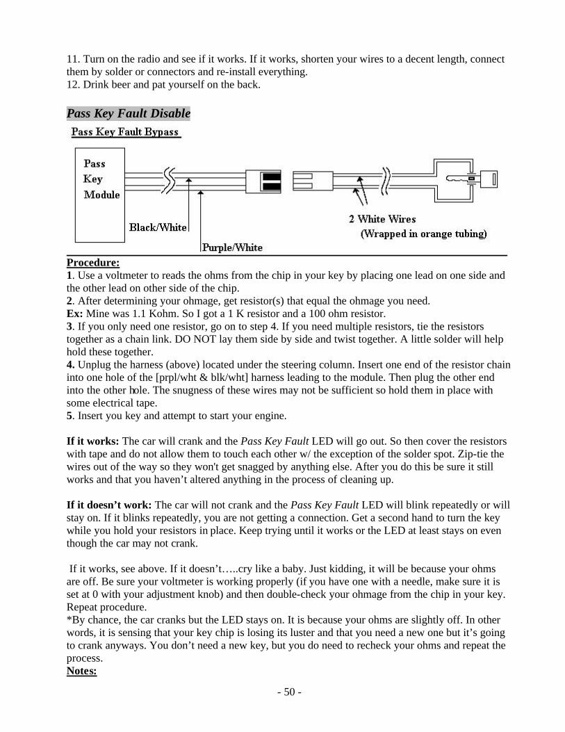
- 50 -
11. Turn on the radio and see if it works. If it works, shorten your wires to a decent length, connect them by solder or connectors and re-install everything. 12. Drink beer and pat yourself on the back. Pass Key Fault Disable
Procedure: 1. Use a voltmeter to reads the ohms from the chip in your key by placing one lead on one side and the other lead on other side of the chip. 2. After determining your ohmage, get resistor(s) that equal the ohmage you need. Ex: Mine was 1.1 Kohm. So I got a 1 K resistor and a 100 ohm resistor. 3. If you only need one resistor, go on to step 4. If you need multiple resistors, tie the resistors together as a chain link. DO NOT lay them side by side and twist together. A little solder will help hold these together. 4. Unplug the harness (above) located under the steering column. Insert one end of the resistor chain into one hole of the [prpl/wht & blk/wht] harness leading to the module. Then plug the other end into the other hole. The snugness of these wires may not be sufficient so hold them in place with some electrical tape. 5. Insert you key and attempt to start your engine. If it works: The car will crank and the Pass Key Fault LED will go out. So then cover the resistors with tape and do not allow them to touch each other w/ the exception of the solder spot. Zip-tie the wires out of the way so they won't get snagged by anything else. After you do this be sure it still works and that you haven’t altered anything in the process of cleaning up. If it doesn’t work: The car will not crank and the Pass Key Fault LED will blink repeatedly or will stay on. If it blinks repeatedly, you are not getting a connection. Get a second hand to turn the key while you hold your resistors in place. Keep trying until it works or the LED at least stays on even though the car may not crank. If it works, see above. If it doesn’t…..cry like a baby. Just kidding, it will be because your ohms are off. Be sure your voltmeter is working properly (if you have one with a needle, make sure it is set at 0 with your adjustment knob) and then double-check your ohmage from the chip in your key. Repeat procedure. *By chance, the car cranks but the LED stays on. It is because your ohms are slightly off. In other words, it is sensing that your key chip is losing its luster and that you need a new one but it’s going to crank anyways. You don’t need a new key, but you do need to recheck your ohms and repeat the process. Notes:

- 51 -
• I went ahead and cut the 2 white wires and soldered in the resistors. It made for a perfect connection. BUT I made sure I had the correct ohmage and that it worked before I went ahead with it.
• Although the module has been disabled, you can not crank the car with a key that does not have the chip in it.
*Special thanks to NyteTyme and RepoSSessor for all the help! Much appreciated. Radar Detector Hidden Power Cord This is pretty simple and I did it because I could not stand to see the power cord dangling from the windshield. First, you will have to cut the power cord and the internal wires are very thin so be careful. Figure out a spot to mount it. I used the spot next to rear view mirror b/c the install was easier than running it through the dash vent. Mainly, you need to route to the fuse box on the drivers side. Extend the power cord if needed. Decide a place to ground the ground wire on the body and connect the power cord to a switched fuse. I would look but my car is gone and I forgot which one I connected it to, it can be “hot-wired” but it will remain on when the car is turned off so be wise in which one you choose. Tachometer
Advantages
Installing the tachometer allows you to monitor engine RPM, a feature that is sorely missed by some 94-95 owners. Other gauges can be installed in '96 models to monitor oil pressure or voltage levels.
Disadvantages
You have to install a non-factory gauge in the interior of the car. It requires some cutting of (replaceable) interior pieces.
Parts Required:
• Replacement black dashboard instrument cluster bezel (P/N ???). Optional, but good insurance. About $15.
• A 2 1/16" tachometer. A Cyberdyne unit is about $50 from JC Whitney or Summit. It has two red digits indicating RPM and goes totally black when the engine is off. JC Whitney also carries a 2 1/16" analog unit for $21 that fits. It has a backlit white and green display (a little dim for some, but it works fine). No matter what you get, make sure it is at most 2 1/16" wide and no deeper than 3 1/2".
• 18 gauge wire and a length of black ribbed wiring conduit. About $5. • Soldering iron or some method of splicing.
Procedure (from Scott Mueller and Rob Cheek) :

- 52 -
1. Remove the black bezel surrounding the instrument cluster by removing the two bolts at the top of it and pulling it back away from the dash. There are three clips at the bottom in the back and two guide posts. Be careful with the rubber ring that goes around the steering column as it is held on by some flimsy plastic rivets and cannot be reattached easily.
2. The tach will go in the right hand side of the black plastic in the bezel to avoid interference with the turn signal and tilt levers and to allow the sacrifice of one of the two clips on the right if need be (the left has but one). If you're careful, you can keep both of them. It will need to rest on or near the point where the smooth grey plastic ends and the molded grey plastic for the rest of the dash begins. Using the tabs and holes as a reference, find where the center of the tach should be if it would rest about 1/8" above the lip and mark the spot on the back of the bezel.
3. Using a 2" hole saw and starting from the back of the bezel, cut out the hole for the tachometer. If you screw it up, don't worry: the bezel is only $15 and you can always try again.
4. Trial fit the tach. If it doesn't fit, work around the exterior of the hole with an Exacto knife until it does. Don't cut too much: it should fit tightly.
5. Cut an identical 2" hole out of the grey plastic behind the bezel. You can re-insert the bezel and use it as a guide. The tach will angle downward slightly, so take this into account.
6. Again, trial fit the tachometer. You may need to cut into the two slots for the clips. Make sure the tach fits in below the clear instrument cover and does not bind. It'll be tight but it will fit. Keep trimming the grey plastic until it does. Repeat ad-nauseum. You might need to cut into one of the rectangular holes for the clips to make it fit.
7. Once it fits in well, make sure the wires are routed so that they'll dangle into the are below the instrument panel and replace the bezel.
8. Remove the access panel below the steering wheel by removing the two screws on the bottom of it. Then remove the steel plate behind it by removing the four bolts and pulling it to the right. The wires for the tach should be dangling down there, or at least accessible from there. Installing a four-way connector here would be a good idea in case you ever need to remove the tach.
9. Tap in a "dimming" or "lights on" signal. The ashtray has both dimming lead and a ground wire going to its light. The wires are also free enough to work with. The grey wire is the dimming wire, and the black wire is the ground.
10. To get power to the tach, you might want to tap into one of the orange wires at the bottom of the fuse box. Check the Helm's manuals for details: you want one that is only hot during run.
11. To get the actual tachometer lead hooked up, you need to route it through the firewall using a factory, unused grommet. Look behind the LH wheelwell. There is an oval, rubber piece there. Now remove the LH kickpanel and look near the point where the hood latch cable exits. If you pull back the insulation, you'll see the same grommet. Use a sharp point to poke a hole in the plug in the firewall, and then squeeze the 18 gauge wire through it. You might have to fish it through using a coathanger or something.
12. The tachometer can take its signal from the black and white wire (negative) terminal at the coil pack on the front of the LH cylinder head. Alternatively, another member has plugged the lead into fourth, unused female terminal on the coil. The both go to the same spot.
13. Another good place to get a tach signal would be from the PCM connector pin A13. All B/F-car PCMs output the tach signal on this pin. You will need a terminal p/n 12084913 (for 20 ga. wire) to install in the PCM A connector (the factory uses a white wire for this application).

- 53 -
14. The wires should be inserted inside of factory ribbed conduit. You can cut a short length and route to one of the factory conduits from the firewall grommet, or route a new conduit all the way to the coil pack.
~Procedure by Scott Mueller & Rob Cheek
Radio Wiring Chart
10 9 8 7 6 5 4 3 2 1
20 19 18 17
Slot: Color: Purpose:
1 Light Gray Left Front Speaker (Negative) 2 Tan Left Front Speaker (Positive) 3 Light Green Right Front Speaker (Negative) 4 Dark Green Right Front Speaker (Positive) 5 Black Ground 6 Not Used 7 Gray Illumination Dimmer Control 8 Pink (Green) Antenna Power 9 Yellow Ignition 12v switched 10 Orange 12v constant battery 17 Light Blue Right Rear Speaker (Negative) 18 Dark Blue Right Rear Speaker (Positive) 19 Yellow Left Rear Speaker (Negative) 20 Brown Left Rear Speaker (Positive)
* http://www.installdr.com/ - Website has installation instructions for any car.
Headlight Instrument Panel Illumination Mine was out for a year because I realized that it had a light behind it. Therefore, I would
always have to feel for my headlight switch. Unfortunately, GM only sells the whole switch for a pretty penny. So here are 2 ways of fixing this. Oh, and yes, you have to remove the lower dash to get to this bulb.
1. You can get a 12-volt micro lamp (Pn# 272-1092C) from Radio Shack and solder it onto the connections, I did it this way and it was tedious b/c of the small soldering spots.
2. After I completed this, lt1ron informed me of a direct replacement made by Honda of all companies. (Pn# 35505S84B02). He says it is a direct replacement w/ no modifications.
Z28 Cluster Change The general purpose of this modification is to update the instrument cluster used in 94-95 Impala SS's, and 94-96 Caprice's. This modification is not easy, and requires extensive work and

- 54 -
time to make it fit and look factory. Your time will vary on the install, and will hopefully take less than mine. You will need to research this out and make sure that you want to do this modification. I will say up front, that after doing it, I love it. Scott Mueller put it best to me, when he said it was the best mod he had done to his car. What part of the car do you interface with more than the instrument cluster? I'll admit that the Digital Cluster was cool when I got it, having the little "Certified" label below it, got some attention, too. But the cluster looked older style (out of the 80's). It just doesn't look like something from the 90's to me. Now that I got this Z-28 cluster in, it works like a champ! Keep in mind you loose a couple of minor idiot lights, nothing major. Heck, I gained a couple. The biggest thing you loose is a gear position indicator, but if you check back in a couple of weeks, I will show you the Dakota Digital product I bought, which will be a nice alternative. It's been operational in my car for over a month now, and works great.
Your first question is probably.. where do I get one? Well, the answer is John Spears, at Speartech Fuel Injection Systems. He is an excellent GM technician, and he makes TONS of custom harnesses for GM car's and other things. I did the whole order through email, and I will tell you, his service is TOP notch. He contacted me to let me know he got his payment, he was willing to answer all my questions, and he gave me a quick turn around time for something custom. I had the cluster in my hands within 4 weeks from the date of order, and I thought this was excellent. The cluster worked like a champ when I got it, and the harness he made to allow it to be plug and play is TOP quality. He does a heck of a job both for service and for quality. I highly recommend him. Visit his page at http://www.speartech.com/. You can email him and he will get back to you within a few days. I think he works more than he gets on the computer, so don't think you are being ignored if you don't get a 1 day return response to your email. Mention my name when you contact him, and tell him Hi for me. The total cost for me, was $355 shipped. This covered the Z-28 Cluster, Adapter Harness (not cheap or easy to make), and the modifications to the cluster to allow it to work properly in the B-body chassis. I initially sent $370, and it ended up being cheaper to ship, he sent me a $15.00 check back, talk about service!

- 55 -
Here are the pictures that show the cluster when I pulled it out of the box that John shipped me. First picture shows what you get, you can see how it fits the black bezel (I thought it was gonna be easy!), and you get a picture of his adapter harness. The spooled up wire is for the tach hook up.

- 56 -
The before and after pictures. At this point I still was not done, and as of this time, I'm still not totally done.

- 57 -
A few pictures of the stuff removed. First thing.. disconnect the negative battery cable, use a 8mm box end wrench to do this. If you minimize what is on in the car, the arcing will be minimal. Have a 7mm socket handy and start removing all the screws from the lower dash (don't forget the one in the ash tray recess). You have to remove the cluster bezel, and then some more 7mm screws that hold the cluster in. Its a little bit difficult to get the cluster out the first time. I thought I was missing something, but after moving it side to side a little and wiggling it back and forth, I got it out without a problem.

- 58 -
These pictures show how I cut the dash support on each side. Now, I cut more than I needed to. You can probably leave an additional two inches on the front side of the dash support, but I wanted clearance, and I wanted to be able to remove the cluster without taking the whole dash apart. I accomplished this task, so I was happy. I used a Dremel tool with a flex shaft extension and 1 fiberglass reinforced cutoff wheel to do all my cutting. It will smoke, and the smell isn't great, and it is messy. Look at my floor, that is just after one side. I then kept test fitting the cluster... looks good... then I cut the left side. You might think.. looks like it fits ok, why cut the left side? Answer:

- 59 -
That is where the harness adapter plugs in. At this point, I had modified the cluster by rounding it as much as I could to match the factory cluster. If you look above at the first pictures, you will see how much I cutoff on the cluster itself. At this point, the cluster has the old lens on it. Notice the column is dropped, so you need to remove the bolts holding that in place (two 16mm nuts if I remember right), so that you can get that big cluster in there.
Now, notice, these pictures are very similar, but taken about 30 minutes apart. Notice on the first picture where the speedometer needle is, compared to the second one. If its on the right side of the dial, it will not pull itself over and work... I yanked the cluster to see if there was an electrical problem, but I could have just taken the lens off and flipped the needle over to the normal side. Once I had the cluster out, I simply turned it upside down and moved the needle that way, using gravity. I then reinstalled it. You will notice that in the first picture, in the lower left corner, there is still a white bracket coming off the cluster, but in the second picture it is gone. I cut all the mounting tabs off the cluster and used some little pieces of metal (used for installing a radio in a dash -rear support-), and cut them with my Dremel and drilled 4 holes in the cluster after getting the cluster in the dash and using my black bezel to get an approximate good location for them. They are straight above/below the factory mounting holes for the Caprice cluster. This allowed for some adjustment to be made for final fitting, and kept me from having to take the factory connectors out of the dash. Its looking good, but FAR from perfect. Though it looks good here, when I put the lower dash back in place, it stuck out too far on the bottom.. so I had to move the cluster further back in the dash. I did a

- 60 -
little minor cutting, your results may vary. Notice the cluster is now raised back into position, for a quick test fit/cluster operation.
Here's the PCM connection being made for the cluster. You have to hook into the RED connector, terminal 13. You need a mini-pack 100 series connector terminal for this. While I was here, I hooked up my Vehicle Speed Sensor signal for my new cruise control install. I used factory style wire conduit to run the wires down to the PCM, and taped them up to look factory. Give it a little dust and you won't be able to tell! <g>. Note: This is with the factory air box removed.

- 61 -
While I was doing the cluster, I figured why not install that replacement Dash Pad I got from Alex on the 9C1 List. Thanks Alex!! But this does give a better view of the cluster, and you know what? The dash pad is very easy to remove, just remove all the screws holding it to the dash (on the front of the dash pad), unsnap the trim piece on the right side of the dash above the glove box (the entire piece, including the A/C vent), and remove the A-pillar moldings, they just pull out with small metal snaps. Once you get all the screws out, just pull back evenly on the entire pad about 3 to 4 inches, and lift the front of it up (this clears the air bag assembly). Installation is the reverse of removal, and really only takes 10 minutes tops to remove it. It might make that cluster install much easier with it removed, as you can really get in there and work, plus you get better light.

- 62 -
I'm getting closer... this is about 95% done. I have done a little after this, but not a whole lot. There is a gap around the cluster, which I am filling with some neat kind of weather stripping. As soon as I get my black bezel fully modified, and get the weather stripping done around the cluster, I will post more pictures. Your final fit will determine how you can cover up the gaps. In any event, its a tight fit on the bottom of the cluster. I even included a night time photo, and in the 9C1 style, my high beams are on! :) On this cluster, I modified the cluster board myself for a couple of things. I enabled the "skip shift" light to now become my "Change Oil Light", and I enabled the ASR light (right, bottom of speedometer), to become my cruise control indicator. Yes folks, I enabled a light on the dash when the cruise control is on. Yes, you can do it.. very simply. If you want to know how, shoot me an email with one of the links at the bottom of this page. Don't forget to order up a new black bezel (good to have a spare), and a new lens for the cluster). These parts were about $25.00. Well worth it and gives you that NEW look. P/N's soon.

- 63 -
If you look closely, this is a preliminary shot of the weather stripping I used around the cluster. I just took this today, and I'm not done with it yet. But if you look closely, it really fills the gap nicely and is consistent around. I'll post a picture of what this stuff looks like. I paid $25.00 for 10 feet of it.. OUCH.. but I wanted a good look, and thought this would fit the bill. Cluster has about 200 miles on it now... boy is it pretty. The Impala guy's at work are a little jealous. I'll just call them Digital boy's.. they can call me Analog Man! <g> I have not put my Dakota Digital gear position indicator in here yet... so, I will be adding that soon.
~David Wambolt [email protected] or [email protected] © 1998 http://www.capricess.com/images/gauges/z28_cluster.htm
INTERIOR
Window Sag PROBLEM: The power window regulators move the door glass via a plastic retainer that slides in a metal guide mounted on the bottom of the glass. The standard equipment plastic retainer is a rectangle with a big hole in the middle where a ball tipped end of each regulator arm snaps into. The plastic fails (breaks) at the narrow sections and releases the arm which causes the window to fall on one side. This happens with age and use. NOTE: I have found this problem on 3 of my 4 doors!! SOLUTION: Replace standard plastic guide with new design window roller: GM P/N 966-6748, List: $1.90 ea. Two required per window. Same part works on all windows. Also, I highly recommend purchasing new door panel retainers as old ones may break or be unusable after inside door panel removal, GM P/N 15600382, $0.43 ea, approximately 5 or 6 required per door. Buy small box of aluminum or steel 3/16 diameter rivets for 1/2" depth HOW: Remove inside door panel, (See Door Panel Removal) (Sounds easy), unsnap regulator arms from bottom glass channel (if attached), REMOVE glass from door. You must first drill out ONLY one of the 3/16 sized pop rivets that are present on each end of the channel AND remove/bend out the stops placed at the end of the channel (the same end as the rivet), Remove old retainers, grease channel with suitable grease (I used a white lithium based grease) and install two

- 64 -
new rollers, replace pop-rivet, slide glass back into door and snap arms into rollers, and reassemble doors. NOTE: You do NOT have to re-bend the channel stop tabs back into place as they were only there to retain the plastic retainers during assembly. EDITOR'S NOTE: From experience, I have found that the rivet does NOT have to be drilled out. Bend out the stops at one end of the channel and tap out the old/broken guides and replace with new roller guides. The stop doesn't have to be be bent back into position. Wow! Sounds easy! Well, it is for those mechanically inclined. The front doors are relatively easy but the back doors are a more difficult as they require you to remove the channel guide in order to remove the glass. Also, getting the arms to snap into the new rollers can be difficult the first time. You must position the glass/arms such that you can get some pliers (in position in the door) to snap the arm into the roller. Heating the rollers helps to ease insertion (warm only as they will melt if too much heat is applied). TOOLS REQUIRED: Phillips screwdriver, POP-Rivet gun/pliers, large pliers, various sized screw drivers for prying etc. OTHER: Please retain part number of window roller otherwise you may have trouble identifying part via standard exploded view diagrams at parts counter (It is not there!!).
Procedure by Mitch Posner
Your problem is the same as many others on the list. The guide in the track has broken. The old versions look like little torpedoes, the new replacements are round and actually roll in the channel. Basically, you remove the door panel, bend the end (right next to the rivet) of the track (or grind a little notch with a dremel tool) on the side that failed, remove the old pink looking carrier (plastic) and replace it with the new teflon round one. After you bend the track at the very end, just inside the rivet (you'll see what I mean if you look at it), then insert the new roller. Take a small 2" C-clamp and press the window arm into the new roller. I can do it in about 10 minutes after the door panel is off. Parts needed are: Rollers for the windows (8 needed to do all windows), PN - 09666748, Bearing (About $1.10ea) Plastic panel fasteners (5ea front door,4 ea back door) PN - 10161510, fastener, Special (about $.19 ea as I recall). I have done at least one roller on each window already and both on the front. When you have the panel off it would help if you put some wheel bearing grease in the track. This will keep the old style from binding and breaking. If you ever have one fail in the down position you can put the window up by having someone guide it while you activate the switch. Need any other help let me know. NOTE - some folks will tell you to drill out the rivet, insert the new roller and replace the rivet with a screw and bolt. It's your choice - but I always go with what's easiest and what works. Getting those rivets out is no easy task. Hope this helps.
Procedure by Ken Orlando http://capricess.com/9c1/technical/info/window_fix.htm
Added Note: There is also an alignment bolt underneath the panel that will cause the window to sag if it becomes loose. I wrongfully diagnosed my problem as a broken roller when all it was was the bolt. It by the metal armrest bracket.
~”QaloSS”

- 65 -
Door panel removal Needed: Panel removal tool or large flathead screwdriver Phillips head screwdriver, large and small Small flathead screwdriver Optional: Extra clips Stainless screws and finishing washers Patience 1. Remove the window switch by prying the front end up and pulling it out, then disconnect the switch wire harnesses. 2. Pull the open lever and remove the small screw behind it, pry the plastic piece out, be VERY careful they tend to break by removing it this way. It’s tricky getting it out due to the locking mechanism so be patient and careful! When it’s out, disconnect the harness to the lock. 3. Next, remove the two large screws behind the caps on the gray pull strap. 4. Remove the two small screws in the armrest 5. Then remove the two left. One is at the bottom of the door panel under the storage pocket and the other is at the top of the storage pocket. 6. No to pop the clips. The removal tool is recommended BUT you can use a large flathead or drywall spatula but be careful, they tend to scratch the paint. 7. Work the clips out all around the panel, there are some in the middle of the panel too. If you break some clips don’t worry, you can get them at a parts store. 8. To lift it off the door, pull gently upwards & out. You may need to pull trim piece off the upper part of the door to get it completely off. 9. The reinstallation is the reverse but here are a few tips:
• Replace any clips that are broken or the feathers have come off of and go ahead and get a bunch, you will probably need them in the future!
• Take special care with the plastic, as I said before, they break very easy and they don’t come cheap and junkyards have already been scavenged for them.
• For the small screws in the armrest, they tend to break through the gray vinyl. I used some stainless steel screws with a wide Stainless finishing washer. It made a nice touch!
• The lock mechanism- be sure that it is aligned and locks and unlocks when you put it back on!
• *The rear doors are basically the same except you do not have power window switches except for one. It pries out easily.

- 66 -
Lower dash Removal 1. Remove the ashtray by taking out the 4 bolts, and disconnect the lighting harness. 2. Remove the 2 bolts in the instrument cluster bezel, and pop it out, you may need to put the shifter in gear 1 for 94 and 95 models. 3. When the bezel is removed remove the screws holding the lower dash in place 4. Take off the fuse box plate to expose 1 bolt and remove it. 5. Now remove the bolts at the lower lip of the lower dash until you get to the glove compartment. 6. Now gently pull the dash off starting from the left side, it will pop out and come off. 7. Installation in the reverse order. Interior Ideas Hey guys...I saw pics of Jayo's interior, and damn it's nice. He said how he colored in the leaping Impala on the back seat, and the SS scripts on the front seat headrests, with a fabric marker, and it looked pretty cool. Well taking a risk I went to the craft store and bought a black fabric marker. I didn't know which to pick, black(color of my car) or red, which I thought would look kinda cool. Well I picked black, and I have no regrets. I need to go over it again and touchup what I need to, but it looks pretty sweet. It matches the outside and is sharp. Makes those scripts and the emblem stand out. The marker only costs 2 bucks. It's a nice accent. Just thought I'd share. Thanks Jayo!
~“ChruiSSer” & “jayo” I had painted a few pieces of my interior and to each his own when it comes to this, but if you paint anything, sand and prime it real good, I used a high heat engine paint, and clear coated it. Of course, spray painting is done best by patience and doing a thin layer at a time so remember that. Also, Auto Zone carries an interior spray paint that is almost an exact match to our cars. I repainted my dash with it and it looked a lot better except that its flat but a little Armor All took care of that. BUT if you do this, be sure to make the dash have a nice rough surface and prime it before painting. Also, be careful with the dash during install and after, being painted and the material it scratches off easier. One last thing, TAKE THE DASH OFF BEFORE YOU TRY TO PAINT IT!
~”QaloSS”
Chapter 3
TROUBLE SHOOTING GUIDE Vibration at high speeds Many different things could cause this vibration. You will probably have to go by the trial and error method. Here are a few things to check:
• Rear Upper Control Arm bushings- will allow the axle to move while on a lift, usually a problem when car has many miles on it (110k+).
• Uneven tire tread wear or wheels not balanced properly. • Driveshaft is not balanced- maybe you hit something or bearings are worn. • Axle Shafts or bearings • Transmission Mounts • Transmission Tail shaft bushings

- 67 -
Temperature gauge not working or acting strange Most likely, your temperature sensor located in the passenger’s side manifold has gone bad. See the procedure for replacing it earlier in this manual. Cooling fans won’t turn on Either your problem is from a blown fuse, bad relay, or your fan motor is gone kaput. If you disconnect the temperature sensor from the water pump while the car is running you can test to see if the fans work. Once you unplug it, both fans will come on. This will disregard fan motors as your problem.
Here is how the fans are suppose to work. This is based on the 96 FSM. Primary Fan (passenger side) will come on if the A/C is on or the temp reaches 225. Fan will turn
off (assuming A/C is off) when the temp reaches 212. Secondary Fan (drivers side) should come on at 232 and shut off around 220. The secondary fan is
not affected by the A/C being on or off. So to answer your question, the primary fan should only come when you start the car and A/C is on or the temp is already 225.
You said that you replace the PCM temp sensor (in the water pump) last fall. Did you use GM or aftermarket? People have complained that the aftermarket ones do not last long. You may want to replace it with a GM part. Also, on other threads related to fans, there have been two cases of a bad battery connection at the starter causing poor fan operation. You may want to check the condition of the wires at the starter and make any necessary repairs.
~”1996ISS Fuel gauge not reading correct amount
This is a common problem among our cars. Unfortunately the only way to fix it is through
the gas tank. There is a fix kit you can purchase from the Superstore. Hesitation, stumble, skipping, missing Probably the most common problem among our cars. Remember hesitation and stumble are more than likely fuel, exhaust, or intake related and skipping and missing are common among ignition and timing problems. Hesitation and Stumble
• EGR Valve and/or Solenoid • Fuel Filter Clogged • Fuel Pump going bad • Fuel sending unit connections melting on fuel pump • Catalytic Converter clogged, glowing red • Idle Air Control Valve • MAF Sensor • Throttle Position Sensor

- 68 -
Skipping and Missing • Heat shield grounding on the plug, remove them. • Bad Spark plug wire • Bad Spark Plug • Optispark going bad • Ignition Coil going bad • Plugs are arching, check at night.
Steering is sluggish and loose
• Idler Arm worn, replace with Problem Solver arm • Steering linkage ball joints are worn, not lubed, or bent • Steering gearbox • Bushings in control arms worn • Bent steering components
Tire wear is not even First, always have you tires rotated and balanced at regular intervals.
• Over inflated (wear to the middle) or under inflated (wear on the edges) • Toe in or pinion angle is off (cause feathering or cupping), have car aligned • Suspension Parts worn
o Control arm bushings o Steering linkage, won’t hold an alignment
• Radical Driving, YES this is a factor “Clunk” shift from 1st to 2nd After repeatedly asking this question as well as others, this is normal and always will be for the 4L60E. It usually happens under slow acceleration around turns and through parking lots. I had my transmission rebuilt and upgraded and it still does it. Pass Key Fault light Either you module is going bad or your key is getting worn enough to where it will start the car but it is causing the LED to come on. Either replace the key (get it from Dal, MUCH cheaper) or the module OR you can disable the feature. See Pass Key Fault procedure Overheating
• Low Coolant or Coolant leak • Thermostat stuck • Fans not working properly • Heater core clogged, from Dye pellets inserted at factory. • Busted Radiator hose • Cracked Head, you’ll know by the smoke billowing out the tailpipe!
- 69 -
“Waterfall” noises
• Drain elbow clogged • Heater core clogged • Elbow came off the drip tube • Air in coolant, bleed the system
Your condensation is pooling in your tray because your elbow came off the driptube.
~uwsacf Could be- air in coolant- check to make sure coolant is up to the required level in the reservoir and use the bleed screw on the thermostat housing on the waterpump to bleed that oxygen out. If that is not your problem, then you need to flush your heater core out. find the two hoses that go into the firewall on the passenger side. disconnect them both from the water pump and flush that bad boy out until the water runs clean. be sure to flush both ways. I had this same problem. The heater worked fine, but it still needed a flush. ~JeffM Heater not blowing hot air Most likely, your heater core is clogged or is malfunctioning. Flush it using the procedure in this manual or replace it.
Water in Passengers side floorboard
• Leaking or clogged Heater Core • Clogged Drain Elbow
If your carpet is wet, then you either have a leak in your heater core, or an outside leak into the cabin. The A/C should not be able to create enough condensation to "Wet" the carpet. The Heater core is on the passengers side, IN the climate box with the A/C system. The heater core seems to last to about 90k to 150k or so, depending on how well the cooling system was maintained. That "pee" hose is for the A/C AND also if you have a leak in the heater core! If you notice a LOT of water coming out, regardless if the A/C is on, then you have a leak. You can get the heater core from any NAPA store (usually in stock) for about 80 bucks (no core charge). Its a NEW part and is not that difficult to replace. Buy a Hayes manual and take your time.
~SBCA96
Blinker not Flashing or won’t Shut Off
• Blown bulb. If the bulb remains on, the car is telling you that you have a bulb out. Check all bulbs for illumination.

- 70 -
• Flasher bad. There are 2 under the drivers lower dash. One for the blinkers and one for the Hazard lights.
• If the “clicker” does not turn off after your turn or will not click. The Turn Signal Switch inside the column has broken. This requires removing the airbag and steering wheel so be sure you know what you’re doing.
Low Windshield Washer Fluid light stays on. The sensor in the reservoir tends to stick. Use the “Fonz” technique by hitting the side of it or remove the reservoir and clean the sensor. That Pesky “Change Oil” light
There are two methods depending on the year. One is to turn on the key "do not start the motor" press the gas pedal to the floor three times and hold it until the change oil light flashes and goes out. The other methods used on the 94s, there is a button inside the fuse box panel on the side of the dash. Turn key on, hold button until change oil flashes and goes out.
~“RJI”
TYPES & BRANDS, OF MAINTENANCE/PERF. PARTS Torque Converters
• B&M • SLP • Vigilante • S-10 Converter
My opinion... and this is coming from someone who has firsthand experience with B&M... their converters suck. You get what you pay for and $125 doesn't buy much. Remember... how many times do you want to pull your trans out of the car for a converter swap? Me, I just want to do it once. I'd spend the money for a SLP converter or a Vigilante. Too much, you say? I work for min wage and have a wife and kid too... Just have to wait longer to get what you want... it's worth it though. Especially for something that difficult to install. But to answer your question, yeah, that converter will work with the stock drive train.
~“Interceptorss” Differential Gear Set TYPE:
• Eaton • Torsen
RATIO:
• 3.08 (Stock) • 3.42 • 3.53

- 71 -
• 3.73 • 4.10 I have owned both. Both are very streetable. The 3.73 will use a little more gas but it will mostly depend on your foot. If your planning on adding a cam then the 3.73 is best. If your looking to spin those big tires the 3.73 wins here too. I use a 3.42 in my 96 because I do 99% highway driving and have an S10 converter and do not plan to do internal mods.
~“RJI” Tire size also plays a part in your decision. If you are going to stick with the stock tire size, then I would also recommend 3.73's, however if you plan to go with a shorter tire, then 3.42's might be a better choice. I am running 275's and 315's, which are about 1.5" shorter than stock. I went with 3.42's. When you calculate the "effective" gear ratio with my tire size, it is roughly equal to 3.69's on a car with stock tire size.
~”2Fasst” Oh, and you want a Torsen differential if you don't plan to drag race... it's better than the Eaton in that case. If you do plan to drag too then get the Eaton.
~“Knightshade Spark Plugs & Wires Plugs
• AC Delco • Rapidfire – not worth the money • Splitfires • Bosch Platinum • NGK
Wires • Taylor • MSD • Magnacor
I’ve spoken with a few mechanics and basically for fuel injected cars, nothing will really give you any gain except Platinum will last longer OR you are running an aftermarket ignition. Stick with the OEM and you’ll be fine. i.e. GM:AC Delco, Mopar:Champion, etc.
~”QaloSS” Oils
Oil Today Today’s oils are products of modern technology and chemistry. The thinner oils perform much better than the blends of yesteryear under high temperature conditions; viscosity breakdown is no longer a serious problem; and the overall film strength is superior. However, the thinner oils are really designed to compliment modern vehicles built since the mid-80s. Car manufacturers tolerances are a lot tighter. The engines are practically blueprinted right out of the factory compared to the sloppy tolerances of 20-30 years ago, and internal clearances have been reduced to take advantage of the lighter oils. Also the advent of fuel injection has allowed consumers to drive the cars as soon as they fire up. Thinner oils help with cold running wear. Also, with fuel injection there’s less oil dilution by overly rich mixtures leaking down into the crankcase past the rings. I would not use 5W- or 10W-30 oils in old tech big blocks, although a premium 20W-50 is more than adequate.

- 72 -
Conversely, thick oil conceivably may cause problems in winter months on late model cars with their tighter internal clearances. In the absence of specific manufacturer guidelines to the contrary, 76 Performance Products recommends 5W-30 for northern-tier states; 10W-30 is preferred for south Texas and similar climate areas. After 100,00 miles step up in viscosity to 10W-40. Any fuel benefits from today’s slicker multiviscosity oils are generally negligible, on the order of 0.1 mpg or so. That’s no big deal to guys like us, but it’s significant to OEM manufactures forced to meet government fuel economy standards. For the purposes of CAFÉ (Corporate Average Fuel Economy) calculations, a model’s fuel mileage is rounded off to the nearest whole number. For example, a car that averages 18.45 mpg is considered an 18-mpg car for the government’s purposes. If thinner oil improves its mileage by 0.1 mpg to 18.55, the mileage rounds up to 19 mpg, which is significant over hundreds of thousands, or even millions, of units when calculating the entire average mileage performance of a given manufacturer’s new car fleet.
~http://www.gmhpclub.com Brands
• Mobil 1 • Castrol Syntec • Castrol Syntec High Mileage
Tires Stock tire size - 255/50 R17 Stock wheel Size - 17 X 8.5
5 X 5 Bolt Pattern 4.95" Offset, J or JJ Flange
Available brands:
• BF Goodrich g-Force KDWS • Nitto NT-450 • BF Goodrich Scorcher T/A • Falken Ziex S/TZ-01
~http://www.capricess.com Best snowtires, reg tires I was looking for some good quality tires to use on my impala SS rims for the winter, I know that they suck in the snow because of how wide the tires need to be, but I found great snow tires and they are good for summer too!! I bought the Kumho Ecsta Stx!! WOW!! They are awesome in the snow!!!! If anyone is looking for a way to keep their rides on the road ! I would recommend these tires!!! I only paid 98$ each plus a 14 mounting charge!!
~”Gold9C1” Belts
• Gatorback • AC Delco

- 73 -
Sway Bars • HO • HA- Herb Adams • 2nd Generation F-Body Sway bar (1970-81 Trans Am/Firebird) • Stock • Hotchkis
Control Arms
• Metco • BMR • Hotchkis • Global West
Appearance Products
• Zaino Bros. http://www.zainobros.com • Zymol • Megueier’s • Mother’s
Programming Many have different opinions about all of these, but consensus rules on Ed and Bryan. The only advantage that HPP has is that you can do the changes yourself. You can with TunerCat, but you need a laptop computer and harness.
Bryan Herter - http://www.pcmforless.com Ed Wright – http://www.fastchip.com
Hypertech Power Programmer III - http://www.hypertech-inc.com/ TunerCat - http://www.tunercat.com/
Springs *The main thing to remember about replacing stock springs with stock ones is that there is 1 set of SS springs and many different ones for the Caprices. So make sure you don’t get springs that the company says are for Caprices/Impalas such as CarParts.Com or JC Whitney.
• Eibach • Intrax • Suspension Technics (ST) • Sprint • Global West

- 74 -
Eibach makes two sets of springs. One for the Caprice and one for the Impala. Both kits will lower the respective car a little over an inch. Either kit can be used on your Caprice. Here's the link for eibach. http://www.eibach.com/index1.htm . The stock Impala springs can be used in the Caprice and allows it to sit the same heigth as the Impala. That is what I have on my Caprice.
~“RJI” Shocks
• Bilstein o Many prefer this brand
• Hal QA1 - 12 ways o Considered to be the best, hands down.
• Edelbrock o Apparent problems with leaking if you have the wrong springs.
• Koni • KYB • GM De-carbon OEM Shocks
o Good ole stockers! • Heavy Duty OEM shocks
o for towing, found with the Caprice • Monroe Sensatrack
o Okay shock, good for the price you pay. Brakes Types:
• Kevlar • Ceramic • Carbon Metallic

- 75 -
Hoods Suncoast Hood SLP Hood
Cowl Induction Hood WS6 Hood
Chapter 4
COMMON ABBREVIATIONS 4L60E – the transmission model that was stock for the LT1 equipped B-Bodies. 4L80E – a replacement transmission for the LT1 that is more heavy duty and handle more horsepower. Air Box – in case you didn’t know, the air filter casing behind the driver’s side AIR FORCE ONE – an alteration for the RAISS intake set up. A metal wind deflector. B- Body – Caprices, Impalas, Roadmasters BBB – Nickname acronym for Black paint color, Some translations are “Big, Black,
Beautiful”, “Bold, Black , Beautiful”, “Big, Black, Bitch”. The actual color name is Standard Onyx Black or SOB.
BLINK BLINKS – sequential brake lights.

- 76 -
BMR – Manufacturer of control arms. CAT EYE GRILL – a type of aftermarket grill, sold from Socal Street Trends LTZ – a certain package for the Caprice. CEL – Check engine Light D- Body – Cadillacs DCM – Paint Color, Dark Cherry Metallic DGGM- Paint Color, Dark Green Gray Metallic DTC - Diagnostic Trouble Code ECM – Electronic Control Module or Engine Control Module EGR – Exhaust Gas Recirculation FB – First Base, the rectangular baffle between the home plate (HP) and the air box. F-Body – Camaros, Firebirds, etc. HA – Herb Adams, refers to a maker of an aftermarket sway bar. HO – refers to a maker of an aftermarket sway bar. HP – Home plate, the home plate shaped baffle on the engine. HP – horse power HPP3 – Hypertech Power Programmer III IMHO – In my honest opinion IMO – In my opinion LCA – Lower Control Arms LED – Light Emitting Diodes, refers to the warning lights in your instrument cluster LS1 – the GM replacement of the LT1, found in new Firebirds, Camaros, Corvettes. LT1 – Your engine man. LT4 – Engine Upgrade. New cam, so on and so on. LT5 – Engine upgrade, Tim Allen’s SS has one. MAF – Mass Air Flow Sensor MIL - Malfunction Indicator Lamp O2 - Oxygen OBD - On Board Diagnostics OBD II - On Board Diagnostics, Generation 2 OEM - Original Equipment Manufacturer PCM – Powertrain Control Module PCV – Positive Crankcase Ventilation valve PITA – Pain in the ass RBT – Red Bow Tie SOB – Standard Onyx Black, see BBB T56 – Type of transmission, replaces the 4L60E, for the manual shift conversion. T84 – an aftermarket headlight kit that shines a lot better than stock. TB – Throttle Body TEFLON TAPE – white tape used to seal threads in order for no fluid leakage. Found in plumbing section of stores. WIG WAGS – police style alternating headlights. WOT – Wide Open Throttle WX3- Code for Super Sports on label in trunk.
AUTOMOTIVE ACRONYM LIST
http://www3.sympatico.ca/dhaughey/j1930.htm#P
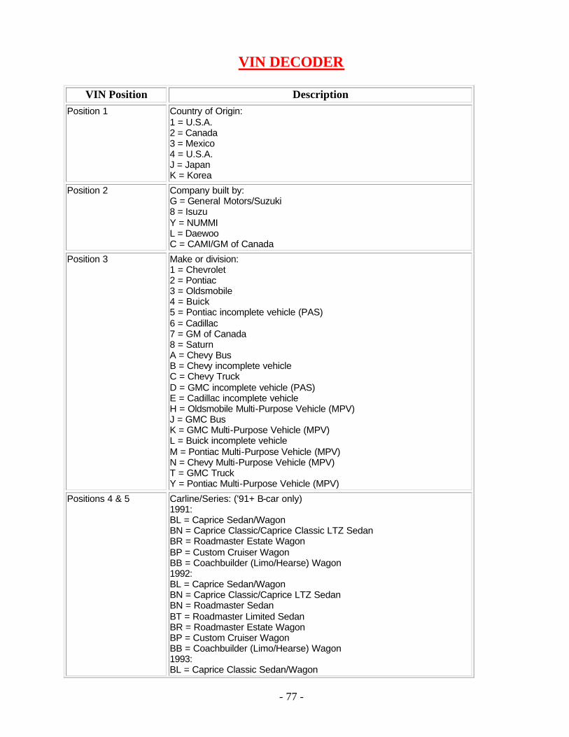
- 77 -
VIN DECODER
VIN Position Description Position 1 Country of Origin:
1 = U.S.A. 2 = Canada 3 = Mexico 4 = U.S.A. J = Japan K = Korea
Position 2 Company built by: G = General Motors/Suzuki 8 = Isuzu Y = NUMMI L = Daewoo C = CAMI/GM of Canada
Position 3 Make or division: 1 = Chevrolet 2 = Pontiac 3 = Oldsmobile 4 = Buick 5 = Pontiac incomplete vehicle (PAS) 6 = Cadillac 7 = GM of Canada 8 = Saturn A = Chevy Bus B = Chevy incomplete vehicle C = Chevy Truck D = GMC incomplete vehicle (PAS) E = Cadillac incomplete vehicle H = Oldsmobile Multi-Purpose Vehicle (MPV) J = GMC Bus K = GMC Multi-Purpose Vehicle (MPV) L = Buick incomplete vehicle M = Pontiac Multi-Purpose Vehicle (MPV) N = Chevy Multi-Purpose Vehicle (MPV) T = GMC Truck Y = Pontiac Multi-Purpose Vehicle (MPV)
Positions 4 & 5 Carline/Series: ('91+ B-car only) 1991: BL = Caprice Sedan/Wagon BN = Caprice Classic/Caprice Classic LTZ Sedan BR = Roadmaster Estate Wagon BP = Custom Cruiser Wagon BB = Coachbuilder (Limo/Hearse) Wagon 1992: BL = Caprice Sedan/Wagon BN = Caprice Classic/Caprice LTZ Sedan BN = Roadmaster Sedan BT = Roadmaster Limited Sedan BR = Roadmaster Estate Wagon BP = Custom Cruiser Wagon BB = Coachbuilder (Limo/Hearse) Wagon 1993: BL = Caprice Classic Sedan/Wagon

- 78 -
BN = Caprice Classic LS/Caprice Classic LTZ Sedan BN = Roadmaster Sedan BT = Roadmaster Limited Sedan BR = Roadmaster Estate Wagon BB = Coachbuilder (Limo/Hearse) Wagon 1994: BL = Caprice Classic Sedan/Wagon BN = Caprice Classic LS/Impala SS Sedan BN = Roadmaster Sedan BT = Roadmaster Limited Sedan BR = Roadmaster Estate Wagon BB = Coachbuilder (Limo/Hearse) Wagon 1995-1996: BL = Caprice Classic Sedan/Wagon, Impala SS Sedan BN = Roadmaster Sedan BT = Roadmaster Limited Sedan BR = Roadmaster Estate Wagon BB = Coachbuilder (Limo/Hearse) Wagon
Position 6 Body style: 1 = 2-door coupe/sedan 2 = 2-door hatchback/liftback 3 = 2-door convertible 4 = 2-door station wagon 5 = 4-door sedan 6 = 4-door hatchback/liftback 7 = 4-door liftback 8 = 4-door station wagon
Position 7 Restraint codes: 1 = Active (manual) belts 2 = Active (manual) belts w/driver & passenger air bags 3 = Active (manual) belts w/driver air bag 4 = Passive (automatic) belts 5 = Passive (automatic) belts w/driver air bag 6 = Passive (automatic) belts w/driver & passenger air bags
Position 8 Engine type: ('91+ B-car only) P = LT1 5.7L - 260 HP @ 5000, 330 lb-ft @ 3200 W = L99 4.3L - 200 HP @ 5200, 245 lb-ft @ 2400 7 = L05 5.7L - 205 HP @ 4400, 300 lb-ft @ 2800 (9C1 Police) 7 = L05 5.7L - 180 HP @ 4200, 300 lb-ft @ 2800 E = L03 5.0L - 170 HP @ 4000, 255 lb-ft @ 2400
Position 9 Check digit: This is a VIN checksum used to verify VIN legality.
Position 10 Model year: A = 1980 B = 1981 C = 1982 D = 1983 E = 1984 F = 1985 G = 1986 H = 1987 J = 1988 K = 1989 L = 1990 M = 1991 N = 1992

- 79 -
P = 1993 R = 1994 S = 1995 T = 1996
Position 11 Plant: A = Lakewood, GA B = Lansing (Reatta), MI B = Baltimore (Truck & Bus), MD B = Pupyong, KOREA C = Lansing, MI D = Doraville, GA E = Linden, NJ E = Pontiac (Truck & Bus), MI F = Fairfax II, KS F = Flint (Truck & Bus), MI G = Framingham, MA H = Flint, MI J = Janesville (Truck & Bus), WI J = Janesville, WI K = Leeds, MO K = Kosai, JAPAN L = Van Nuys ('82-'92 F-car), CA M = Lansing, MI N = Norwood ('82-'87 F-car), OH R = Arlington (B-car), TX S = St. Louis (Truck & Bus), MO S = Ramos Arizpe, MEXICO T = Tarrytown (Truck & Bus), NY U = Hamtramck, MI V = Pontiac (Truck & Bus), MI W = Willow Run (B-car), MI W = Iwata, JAPAN X = Fairfax, KS Y = Wilmington, DE Z = Fremont, CA Z = Spring Hill (Saturn), TN Z = Fort Wayne (Truck & Bus), IN 0 = Pontiac (Truck & Bus), MI 1 = Wentzville, MO 1 = Oshowa 2, ONTARIO 2 = Moraine (Truck & Bus), OH 2 = Ste. Therese ('93-'96+ F-car), QUEBEC 3 = Detroit (Truck & Bus), MI 3 = Kawasaki, JAPAN 3 = St. Eustache, QUEBEC 4 = Orion, MI 4 = Scarborough, ONTARIO 5 = Bowling Green ('84-'96+ Corvette), KY 5 = London, ONTARIO 6 = Oklahoma City, OK 6 = Ingersoll, ONTARIO 7 = Lordstown, OH 7 = Lordstown (Truck & Bus), OH 7 = Fujisawa, JAPAN 8 = Shreveport (Truck & Bus), LA 9 = Detroit, MI 9 = Tillsonburg, ONTARIO

- 80 -
9 = Oshawa 1, ONTARIO Positions 12-17 Sequence Number:
100001 = 1st vehicle 200001 = 100001st vehicle, etc.
Provided by Scott Mueller http://www.theherd.com/articles/gmvin.html
* The VIN won’t tell you if it’s a SS or not. The code “WX3” on the trunk lid decal will contain this code. It is the SS style package code.
SERVICE INTERVALS
Transmission Fluid – 30,000 miles Oil – 3,000 miles/3 months Differential – 15,000 miles Plug Wires – 75-100,000 miles Plugs – 30,000 miles Air filter – 6-12 months Fuel filter- 40,000 miles Rotation – 6,000 miles/6 months Balance – 6,000 miles/6 months or as needed Alignment – 12,000 miles or as needed Chassis Lube – 3,000 miles/3 months O2 sensors- 100,000 miles Serpentine Belt – 30-60,000 miles PCV Valve – 6-12 months Coolant – annually for the green stuff
IMPALA SPECIFICATIONS/CAPACITIES How to tell the difference, is it a real SS or a clone? OBD OBD I on 91-95, OBD II on 96-present SHIFTER Floor shifter in 1996 only ANALOG DASH Digital dash in 94 and 95, analog in 1996 New dash design came in 94, 93 and before had the elongated dash . WINDOWS 94 had quarter window plates, 95 and 96 had metal insertion. O2 SENSORS 94 and 95 have 2 before the cats, 96’s have 4; 2 before and 2 after. GENERAL Check for a “WX3” code on the label in the trunk. It’s is the code for the SS body package. ENGINE

- 81 -
1994 had an overflow tube for the coolant reservoir tank INTERIOR 1996 have seat belt clasp covers, matched gray to paneling. Capacities – **not finished**
DTC – DIAGNOSTIC TROUBLE CODES OBD I – On Board Diagnostic, Gen. 1 http://autorepair.about.com/library/ts/obd-i/bl-dtcs-main.htm
*Found on 1995 and before models.
13 Open Oxygen Sensor Circuit 14 Coolant Temperature Sensor (High Temp Indicated) 15 Coolant Temperature Sensor (Low Temp Indicated) 21 Throttle Position Sensor (Signal Voltage High) 22 Throttle Position Sensor (Signal Voltage Low) 23 Manifold Air Temperature (MAT) Low Temp Indicated 24 Vehicle Speed Sensor (VSS) Circuit 25 Manifold Air Temperature (MAT) High Temp Indicated 32 Exhaust Gas Recirculation (EGR) Circuit 33 Manifold Absolute Pressure Sensor Circuit (High Sig.) 34 Manifold Absolute Pressure Sensor Circuit (Low Sig.) 35 Idle Air Control (IAC) 41 Cylinder Select Error 42 Ignition Control (IC) Circuit 43 Knock Sensor (KS) Circuit 44 Oxygen Sensor Circuit (Lean Exhaust Indicated) 45 Oxygen Sensor Circuit (Rich Exhaust Indicated) 51 EEPROM or ECM Failure 53 System Voltage Overcharge
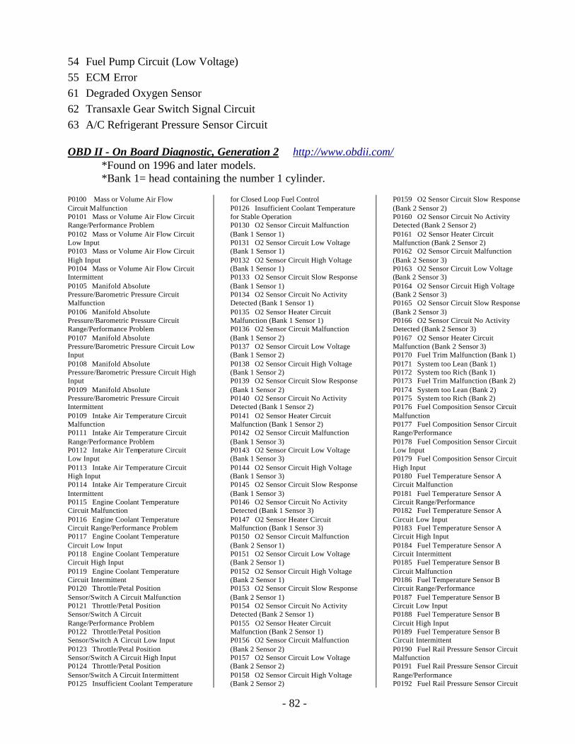
- 82 -
54 Fuel Pump Circuit (Low Voltage) 55 ECM Error 61 Degraded Oxygen Sensor 62 Transaxle Gear Switch Signal Circuit 63 A/C Refrigerant Pressure Sensor Circuit OBD II - On Board Diagnostic, Generation 2 http://www.obdii.com/
*Found on 1996 and later models. *Bank 1= head containing the number 1 cylinder.
P0100 Mass or Volume Air Flow Circuit Malfunction P0101 Mass or Volume Air Flow Circuit Range/Performance Problem P0102 Mass or Volume Air Flow Circuit Low Input P0103 Mass or Volume Air Flow Circuit High Input P0104 Mass or Volume Air Flow Circuit Intermittent P0105 Manifold Absolute Pressure/Barometric Pressure Circuit Malfunction P0106 Manifold Absolute Pressure/Barometric Pressure Circuit Range/Performance Problem P0107 Manifold Absolute Pressure/Barometric Pressure Circuit Low Input P0108 Manifold Absolute Pressure/Barometric Pressure Circuit High Input P0109 Manifold Absolute Pressure/Barometric Pressure Circuit Intermittent P0109 Intake Air Temperature Circuit Malfunction P0111 Intake Air Temperature Circuit Range/Performance Problem P0112 Intake Air Temperature Circuit Low Input P0113 Intake Air Temperature Circuit High Input P0114 Intake Air Temperature Circuit Intermittent P0115 Engine Coolant Temperature Circuit Malfunction P0116 Engine Coolant Temperature Circuit Range/Performance Problem P0117 Engine Coolant Temperature Circuit Low Input P0118 Engine Coolant Temperature Circuit High Input P0119 Engine Coolant Temperature Circuit Intermittent P0120 Throttle/Petal Position Sensor/Switch A Circuit Malfunction P0121 Throttle/Petal Position Sensor/Switch A Circuit Range/Performance Problem P0122 Throttle/Petal Position Sensor/Switch A Circuit Low Input P0123 Throttle/Petal Position Sensor/Switch A Circuit High Input P0124 Throttle/Petal Position Sensor/Switch A Circuit Intermittent P0125 Insufficient Coolant Temperature
for Closed Loop Fuel Control P0126 Insufficient Coolant Temperature for Stable Operation P0130 O2 Sensor Circuit Malfunction (Bank 1 Sensor 1) P0131 O2 Sensor Circuit Low Voltage (Bank 1 Sensor 1) P0132 O2 Sensor Circuit High Voltage (Bank 1 Sensor 1) P0133 O2 Sensor Circuit Slow Response (Bank 1 Sensor 1) P0134 O2 Sensor Circuit No Activity Detected (Bank 1 Sensor 1) P0135 O2 Sensor Heater Circuit Malfunction (Bank 1 Sensor 1) P0136 O2 Sensor Circuit Malfunction (Bank 1 Sensor 2) P0137 O2 Sensor Circuit Low Voltage (Bank 1 Sensor 2) P0138 O2 Sensor Circuit High Voltage (Bank 1 Sensor 2) P0139 O2 Sensor Circuit Slow Response (Bank 1 Sensor 2) P0140 O2 Sensor Circuit No Activity Detected (Bank 1 Sensor 2) P0141 O2 Sensor Heater Circuit Malfunction (Bank 1 Sensor 2) P0142 O2 Sensor Circuit Malfunction (Bank 1 Sensor 3) P0143 O2 Sensor Circuit Low Voltage (Bank 1 Sensor 3) P0144 O2 Sensor Circuit High Voltage (Bank 1 Sensor 3) P0145 O2 Sensor Circuit Slow Response (Bank 1 Sensor 3) P0146 O2 Sensor Circuit No Activity Detected (Bank 1 Sensor 3) P0147 O2 Sensor Heater Circuit Malfunction (Bank 1 Sensor 3) P0150 O2 Sensor Circuit Malfunction (Bank 2 Sensor 1) P0151 O2 Sensor Circuit Low Voltage (Bank 2 Sensor 1) P0152 O2 Sensor Circuit High Voltage (Bank 2 Sensor 1) P0153 O2 Sensor Circuit Slow Response (Bank 2 Sensor 1) P0154 O2 Sensor Circuit No Activity Detected (Bank 2 Sensor 1) P0155 O2 Sensor Heater Circuit Malfunction (Bank 2 Sensor 1) P0156 O2 Sensor Circuit Malfunction (Bank 2 Sensor 2) P0157 O2 Sensor Circuit Low Voltage (Bank 2 Sensor 2) P0158 O2 Sensor Circuit High Voltage (Bank 2 Sensor 2)
P0159 O2 Sensor Circuit Slow Response (Bank 2 Sensor 2) P0160 O2 Sensor Circuit No Activity Detected (Bank 2 Sensor 2) P0161 O2 Sensor Heater Circuit Malfunction (Bank 2 Sensor 2) P0162 O2 Sensor Circuit Malfunction (Bank 2 Sensor 3) P0163 O2 Sensor Circuit Low Voltage (Bank 2 Sensor 3) P0164 O2 Sensor Circuit High Voltage (Bank 2 Sensor 3) P0165 O2 Sensor Circuit Slow Response (Bank 2 Sensor 3) P0166 O2 Sensor Circuit No Activity Detected (Bank 2 Sensor 3) P0167 O2 Sensor Heater Circuit Malfunction (Bank 2 Sensor 3) P0170 Fuel Trim Malfunction (Bank 1) P0171 System too Lean (Bank 1) P0172 System too Rich (Bank 1) P0173 Fuel Trim Malfunction (Bank 2) P0174 System too Lean (Bank 2) P0175 System too Rich (Bank 2) P0176 Fuel Composition Sensor Circuit Malfunction P0177 Fuel Composition Sensor Circuit Range/Performance P0178 Fuel Composition Sensor Circuit Low Input P0179 Fuel Composition Sensor Circuit High Input P0180 Fuel Temperature Sensor A Circuit Malfunction P0181 Fuel Temperature Sensor A Circuit Range/Performance P0182 Fuel Temperature Sensor A Circuit Low Input P0183 Fuel Temperature Sensor A Circuit High Input P0184 Fuel Temperature Sensor A Circuit Intermittent P0185 Fuel Temperature Sensor B Circuit Malfunction P0186 Fuel Temperature Sensor B Circuit Range/Performance P0187 Fuel Temperature Sensor B Circuit Low Input P0188 Fuel Temperature Sensor B Circuit High Input P0189 Fuel Temperature Sensor B Circuit Intermittent P0190 Fuel Rail Pressure Sensor Circuit Malfunction P0191 Fuel Rail Pressure Sensor Circuit Range/Performance P0192 Fuel Rail Pressure Sensor Circuit

- 83 -
Low Input P0193 Fuel Rail Pressure Sensor Circuit High Input P0194 Fuel Rail Pressure Sensor Circuit Intermittent P0195 Engine Oil Temperature Sensor Malfunction P0196 Engine Oil Temperature Sensor Range/Performance P0197 Engine Oil Temperature Sensor Low P0198 Engine Oil Temperature Sensor High P0199 Engine Oil Temperature Sensor Intermittent P0200 Injector Circuit Malfunction P0201 Injector Circuit Malfunction - Cylinder 1 P0202 Injector Circuit Malfunction - Cylinder 2 P0203 Injector Circuit Malfunction - Cylinder 3 P0204 Injector Circuit Malfunction - Cylinder 4 P0205 Injector Circuit Malfunction - Cylinder 5 P0206 Injector Circuit Malfunction - Cylinder 6 P0207 Injector Circuit Malfunction - Cylinder 7 P0208 Injector Circuit Malfunction - Cylinder 8 P0209 Injector Circuit Malfunction - Cylinder 9 P0210 Injector Circuit Malfunction - Cylinder 10 P0211 Injector Circuit Malfunction - Cylinder 11 P0212 Injector Circuit Malfunction - Cylinder 12 P0213 Cold Start Injector 1 Malfunction P0214 Cold Start Injector 2 Malfunction P0215 Engine Shutoff Solenoid Malfunction P0216 Injection Timing Control Circuit Malfunction P0217 Engine Overtemp Condition P0218 Transmission Over Temperature Condition P0219 Engine Overspeed Condition P0220 Throttle/Petal Position Sensor/Switch B Circuit Malfunction P0221 Throttle/Petal Position Sensor/Switch B Circuit Range/Performance Problem P0222 Throttle/Petal Position Sensor/Switch B Circuit Low Input P0223 Throttle/Petal Position Sensor/Switch B Circuit High Input P0224 Throttle/Petal Position Sensor/Switch B Circuit Intermittent P0225 Throttle/Petal Position Sensor/Switch C Circuit Malfunction P0226 Throttle/Petal Position Sensor/Switch C Circuit Range/Performance Problem P0227 Throttle/Petal Position Sensor/Switch C Circuit Low Input P0228 Throttle/Petal Position Sensor/Switch C Circuit High Input P0229 Throttle/Petal Position Sensor/Switch C Circuit Intermittent P0230 Fuel Pump Primary Circuit
Malfunction P0231 Fuel Pump Secondary Circuit Low P0232 Fuel Pump Secondary Circuit High P0233 Fuel Pump Secondary Circuit Intermittent P0234 Engine Overboost Condition P0235 Turbocharger Boost Sensor A Circuit Malfunction P0236 Turbocharger Boost Sensor A Circuit Range/Performance P0237 Turbocharger Boost Sensor A Circuit Low P0238 Turbocharger Boost Sensor A Circuit High P0239 Turbocharger Boost Sensor B Malfunction P0240 Turbocharger Boost Sensor B Circuit Range/Performance P0241 Turbocharger Boost Sensor B Circuit Low P0242 Turbocharger Boost Sensor B Circuit High P0243 Turbocharger Wastegate Solenoid A Malfunction P0244 Turbocharger Wastegate Solenoid A Range/Performance P0245 Turbocharger Wastegate Solenoid A Low P0246 Turbocharger Wastegate Solenoid A High P0247 Turbocharger Wastegate Solenoid B Malfunction P0248 Turbocharger Wastegate Solenoid B Range/Performance P0249 Turbocharger Wastegate Solenoid B Low P0250 Turbocharger Wastegate Solenoid B High P0251 Injection Pump Fuel Metering Control "A" Malfunction (Cam/Rotor/Injector) P0252 Injection Pump Fuel Metering Control "A" Range/Performance (Cam/Rotor/Injector) P0253 Injection Pump Fuel Metering Control "A" Low (Cam/Rotor/Injector) P0254 Injection Pump Fuel Metering Control "A" High (Cam/Rotor/Injector) P0255 Injection Pump Fuel Metering Control "A" Intermittent (Cam/Rotor/Injector) P0256 Injection Pump Fuel Metering Control "B" Malfunction (Cam/Rotor/Injector) P0257 Injection Pump Fuel Metering Control "B" Range/Performance (Cam/Rotor/Injector) P0258 Injection Pump Fuel Metering Control "B" Low (Cam/Rotor/Injector) P0259 Injection Pump Fuel Metering Control "B" High (Cam/Rotor/Injector) P0260 Injection Pump Fuel Metering Control "B" Intermittent (Cam/Rotor/Injector) P0261 Cylinder 1 Injector Circuit Low P0262 Cylinder 1 Injector Circuit High P0263 Cylinder 1 Contribution/Balance Fault P0264 Cylinder 2 Injector Circuit Low P0265 Cylinder 2 Injector Circuit High P0266 Cylinder 2 Contribution/Balance
Fault P0267 Cylinder 3 Injector Circuit Low P0268 Cylinder 3 Injector Circuit High P0269 Cylinder 3 Contribution/Balance Fault P0270 Cylinder 4 Injector Circuit Low P0271 Cylinder 4 Injector Circuit High P0272 Cylinder 4 Contribution/Balance Fault P0273 Cylinder 5 Injector Circuit Low P0274 Cylinder 5 Injector Circuit High P0275 Cylinder 5 Contribution/Balance Fault P0276 Cylinder 6 Injector Circuit Low P0277 Cylinder 6 Injector Circuit High P0278 Cylinder 6 Contribution/Balance Fault P0279 Cylinder 7 Injector Circuit Low P0280 Cylinder 7 Injector Circuit High P0281 Cylinder 7 Contribution/Balance Fault P0282 Cylinder 8 Injector Circuit Low P0283 Cylinder 8 Injector Circuit High P0284 Cylinder 8 Contribution/Balance Fault P0285 Cylinder 9 Injector Circuit Low P0286 Cylinder 9 Injector Circuit High P0287 Cylinder 9 Contribution/Balance Fault P0288 Cylinder 10 Injector Circuit Low P0289 Cylinder 10 Injector Circuit High P0290 Cylinder 10 Contribution/Balance Fault P0291 Cylinder 11 Injector Circuit Low P0292 Cylinder 11 Injector Circuit High P0293 Cylinder 11 Contribution/Balance Fault P0294 Cylinder 12 Injector Circuit Low P0295 Cylinder 12 Injector Circuit High P0296 Cylinder 12 Contribution/Range Fault P0300 Random/Multiple Cylinder Misfire Detected P0301 Cylinder 1 Misfire Detected P0302 Cylinder 2 Misfire Detected P0303 Cylinder 3 Misfire Detected P0304 Cylinder 4 Misfire Detected P0305 Cylinder 5 Misfire Detected P0306 Cylinder 6 Misfire Detected P0307 Cylinder 7 Misfire Detected P0308 Cylinder 8 Misfire Detected P0309 Cylinder 9 Misfire Detected P0311 Cylinder 11 Misfire Detected P0312 Cylinder 12 Misfire Detected P0320 Ignition/Distributor Engine Speed Input Circuit Malfunction P0321 Ignition/Distributor Engine Speed Input Circuit Range/Performance P0322 Ignition/Distributor Engine Speed Input Circuit No Signal P0323 Ignition/Distributor Engine Speed Input Circuit Intermittent P0325 Knock Sensor 1 Circuit Malfunction (Bank 1 or Single Sensor) P0326 Knock Sensor 1 Circuit Range/Performance (Bank 1 or Single Sensor) P0327 Knock Sensor 1 Circuit Low Input (Bank 1 or Single Sensor) P0328 Knock Sensor 1 Circuit High Input (Bank 1 or Single Sensor) P0329 Knock Sensor 1 Circuit Intermittent (Bank 1 or Single Sensor)

- 84 -
P0330 Knock Sensor 2 Circuit Malfunction (Bank 2) P0331 Knock Sensor 2 Circuit Range/Performance (Bank 2) P0332 Knock Sensor 2 Circuit Low Input (Bank 2) P0333 Knock Sensor 2 Circuit High Input (Bank 2) P0334 Knock Sensor 2 Circuit Intermittent (Bank 2) P0335 Crankshaft Position Sensor A Circuit Malfunction P0336 Crankshaft Position Sensor A Circuit Range/Performance P0337 Crankshaft Position Sensor A Circuit Low Input P0338 Crankshaft Position Sensor A Circuit High Input P0339 Crankshaft Position Sensor A Circuit Intermittent P0340 Camshaft Position Sensor Circuit Malfunction P0341 Camshaft Position Sensor Circuit Range/Performance P0342 Camshaft Position Sensor Circuit Low Input P0343 Camshaft Position Sensor Circuit High Input P0344 Camshaft Position Sensor Circuit Intermittent P0350 Ignition Coil Primary/Secondary Circuit Malfunction P0351 Ignition Coil A Primary/Secondary Circuit Malfunction P0352 Ignition Coil B Primary/Secondary Circuit Malfunction P0353 Ignition Coil C Primary/Secondary Circuit Malfunction P0354 Ignition Coil D Primary/Secondary Circuit Malfunction P0355 Ignition Coil E Primary/Secondary Circuit Malfunction P0356 Ignition Coil F Primary/Secondary Circuit Malfunction P0357 Ignition Coil G Primary/Secondary Circuit Malfunction P0358 Ignition Coil H Primary/Secondary Circuit Malfunction P0359 Ignition Coil I Primary/Secondary Circuit Malfunction P0360 Ignition Coil J Primary/Secondary Circuit Malfunction P0361 Ignition Coil K Primary/Secondary Circuit Malfunction P0362 Ignition Coil L Primary/Secondary Circuit Malfunction P0370 Timing Reference High Resolution Signal A Malfunction P0371 Timing Reference High Resolution Signal A Too Many Pulses P0372 Timing Reference High Resolution Signal A Too Few Pulses P0373 Timing Reference High Resolution Signal A Intermittent/Erratic Pulses P0374 Timing Reference High Resolution Signal A No Pulses P0375 Timing Reference High Resolution Signal B Malfunction P0376 Timing Reference High Resolution Signal B Too Many Pulses P0377 Timing Reference High Resolution Signal B Too Few Pulses
P0378 Timing Reference High Resolution Signal B Intermittent/Erratic Pulses P0379 Timing Reference High Resolution Signal B No Pulses P0380 Glow Plug/Heater Circuit "A" Malfunction P0381 Glow Plug/Heater Indicator Circuit Malfunction P0382 Exhaust Gas Recirculation Flow Malfunction P0385 Crankshaft Position Sensor B Circuit Malfunction P0386 Crankshaft Position Sensor B Circuit Range/Performance P0387 Crankshaft Position Sensor B Circuit Low Input P0388 Crankshaft Position Sensor B Circuit High Input P0389 Crankshaft Position Sensor B Circuit Intermittent P0400 Exhaust Gas Recirculation Flow Malfunction P0401 Exhaust Gas Recirculation Flow Insufficient Detected P0402 Exhaust Gas Recirculation Flow Excessive Detected P0403 Exhaust Gas Recirculation Circuit Malfunction P0404 Exhaust Gas Recirculation Circuit Range/Performance P0405 Exhaust Gas Recirculation Sensor A Circuit Low P0406 Exhaust Gas Recirculation Sensor A Circuit High P0407 Exhaust Gas Recirculation Sensor B Circuit Low P0408 Exhaust Gas Recirculation Sensor B Circuit High P0410 Secondary Air Injection System Malfunction P0411 Secondary Air Injection System Incorrect Flow Detected P0412 Secondary Air Injection System Switching Valve A Circuit Malfunction P0413 Secondary Air Injection System Switching Valve A Circuit Open P0414 Secondary Air Injection System Switching Valve A Circuit Shorted P0415 Secondary Air Injection System Switching Valve B Circuit Malfunction P0416 Secondary Air Injection System Switching Valve B Circuit Open P0417 Secondary Air Injection System Switching Valve B Circuit Shorted P0418 Secondary Air Injection System Relay "A" Circuit Malfunction P0419 Secondary Air Injection System Relay "B" Circuit Malfunction P0420 Catalyst System Efficiency Below Threshold (Bank 1) P0421 Warm Up Catalyst Efficiency Below Threshold (Bank 1) P0422 Main Catalyst Efficiency Below Threshold (Bank 1) P0423 Heated Catalyst Efficiency Below Threshold (Bank 1) P0424 Heated Catalyst Temperature Below Threshold (Bank 1) P0430 Catalyst System Efficiency Below Threshold (Bank 2) P0431 Warm Up Catalyst Efficiency Below Threshold (Bank 2)
P0432 Main Catalyst Efficiency Below Threshold (Bank 2) P0433 Heated Catalyst Efficiency Below Threshold (Bank 2) P0434 Heated Catalyst Temperature Below Threshold (Bank 2) P0440 Evaporative Emission Control System Malfunction P0441 Evaporative Emission Control System Incorrect Purge Flow P0442 Evaporative Emission Control System Leak Detected (small leak) P0443 Evaporative Emission Control System Purge Control Valve Circuit Malfunction P0444 Evaporative Emission Control System Purge Control Valve Circuit Open P0445 Evaporative Emission Control System Purge Control Valve Circuit Shorted P0446 Evaporative Emission Control System Vent Control Circuit Malfunction P0447 Evaporative Emission Control System Vent Control Circuit Open P0448 Evaporative Emission Control System Vent Control Circuit Shorted P0449 Evaporative Emission Control System Vent Valve/Solenoid Circuit Malfunction P0450 Evaporative Emission Control System Pressure Sensor Malfunction P0451 Evaporative Emission Control System Pressure Sensor Range/Performance P0452 Evaporative Emission Control System Pressure Sensor Low Input P0453 Evaporative Emission Control System Pressure Sensor High Input P0454 Evaporative Emission Control System Pressure Sensor Intermittent P0455 Evaporative Emission Control System Leak Detected (gross leak) P0460 Fuel Level Sensor Circuit Malfunction P0461 Fuel Level Sensor Circuit Range/Performance P0462 Fuel Level Sensor Circuit Low Input P0463 Fuel Level Sensor Circuit High Input P0464 Fuel Level Sensor Circuit Intermittent P0465 Purge Flow Sensor Circuit Malfunction P0466 Purge Flow Sensor Circuit Range/Performance P0467 Purge Flow Sensor Circuit Low Input P0468 Purge Flow Sensor Circuit High Input P0469 Purge Flow Sensor Circuit Intermittent P0470 Exhaust Pressure Sensor Malfunction P0471 Exhaust Pressure Sensor Range/Performance P0472 Exhaust Pressure Sensor Low P0473 Exhaust Pressure Sensor High P0474 Exhaust Pressure Sensor Intermittent P0475 Exhaust Pressure Control Valve Malfunction P0476 Exhaust Pressure Control Valve

- 85 -
Range/Performance P0477 Exhaust Pressure Control Valve Low P0478 Exhaust Pressure Control Valve High P0479 Exhaust Pressure Control Valve Intermittent P0480 Cooling Fan 1 Control Circuit Malfunction P0481 Cooling Fan 2 Control Circuit Malfunction P0482 Cooling Fan 3 Control Circuit Malfunction P0483 Cooling Fan Rationality Check Malfunction P0484 Cooling Fan Circuit Over Current P0485 Cooling Fan Power/Ground Circuit Malfunction P0500 Vehicle Speed Sensor Malfunction P0501 Vehicle Speed Sensor Range/Performance P0502 Vehicle Speed Sensor Low Input P0503 Vehicle Speed Sensor Intermittent/Erratic/High P0505 Idle Control System Malfunction P0506 Idle Control System RPM Lower Than Expected P0507 Idle Control System RPM Higher Than Expected P0510 Closed Throttle Position Switch Malfunction P0520 Engine Oil Pressure Sensor/Switch Circuit Malfunction P0521 Engine Oil Pressure Sensor/Switch Circuit Range/Performance P0522 Engine Oil Pressure Sensor/Switch Circuit Low Voltage P0523 Engine Oil Pressure Sensor/Switch Circuit High Voltage P0530 A/C Refrigerant Pressure Sensor Circuit Malfunction P0531 A/C Refrigerant Pressure Sensor Circuit Range/Performance P0532 A/C Refrigerant Pressure Sensor Circuit Low Input P0533 A/C Refrigerant Pressure Sensor Circuit High Input P0534 Air Conditioner Refrigerant Charge Loss P0550 Power Steering Pressure Sensor Circuit Malfunction P0551 Power Steering Pressure Sensor Circuit Range/Performance P0552 Power Steering Pressure Sensor Circuit Low Input P0553 Power Steering Pressure Sensor Circuit High Input P0554 Power Steering Pressure Sensor Circuit Intermittent P0560 System Voltage Malfunction P0561 System Voltage Unstable P0562 System Voltage Low P0563 System Voltage High P0565 Cruise Control On Signal Malfunction P0566 Cruise Control Off Signal Malfunction P0567 Cruise Control Resume Signal Malfunction P0568 Cruise Control Set Signal Malfunction P0569 Cruise Control Coast Signal
Malfunction P0570 Cruise Control Accel Signal Malfunction P0571 Cruise Control/Brake Switch A Circuit Malfunction P0572 Cruise Control/Brake Switch A Circuit Low P0573 Cruise Control/Brake Switch A Circuit High P0574 Cruise Control Related Malfunction P0575 Cruise Control Related Malfunction P0576 Cruise Control Related Malfunction P0576 Cruise Control Related Malfunction P0578 Cruise Control Related Malfunction P0579 Cruise Control Related Malfunction P0580 Cruise Control Related Malfunction P0600 Serial Communication Link Malfunction P0601 Internal Control Module Memory Check Sum Error P0602 Control Module Programming Error P0603 Internal Control Module Keep Alive Memory (KAM) Error P0604 Internal Control Module Random Access Memory (RAM) Error P0605 Internal Control Module Read Only Memory (ROM) Error P0606 PCM Processor Fault P0608 Control Module VSS Output "A" Malfunction P0609 Control Module VSS Output "B" Malfunction P0620 Generator Control Circuit Malfunction P0621 Generator Lamp "L" Control Circuit Malfunction P0622 Generator Field "F" Control Circuit Malfunction P0650 Malfunction Indicator Lamp (MIL) Control Circuit Malfunction P0654 Engine RPM Output Circuit Malfunction P0655 Engine Hot Lamp Output Control Circuit Malfucntion P0656 Fuel Level Output Circuit Malfunction P0700 Transmission Control System Malfunction P0701 Transmission Control System Range/Performance P0702 Transmission Control System Electrical P0703 Torque Converter/Brake Switch B Circuit Malfunction P0704 Clutch Switch Input Circuit Malfunction P0705 Transmission Range Sensor Circuit malfunction (PRNDL Input) P0706 Transmission Range Sensor Circuit Range/Performance P0707 Transmission Range Sensor Circuit Low Input P0708 Transmission Range Sensor Circuit High Input P0709 Transmission Range Sensor
Circuit Intermittent P0710 Transmission Fluid Temperature Sensor Circuit Malfunction P0711 Transmission Fluid Temperature Sensor Circuit Range/Performance P0712 Transmission Fluid Temperature Sensor Circuit Low Input P0713 Transmission Fluid Temperature Sensor Circuit High Input P0714 Transmission Fluid Temperature Sensor Circuit Intermittent P0715 Input/Turbine Speed Sensor Circuit Malfunction P0716 Input/Turbine Speed Sensor Circuit Range/Performance P0717 Input/Turbine Speed Sensor Circuit No Signal P0718 Input/Turbine Speed Sensor Circuit Intermittent P0719 Torque Converter/Brake Switch B Circuit Low P0720 Output Speed Sensor Circuit Malfunction P0721 Output Speed Sensor Range/Performance P0722 Output Speed Sensor No Signal P0723 Output Speed Sensor Intermittent P0724 Torque Converter/Brake Switch B Circuit High P0725 Engine Speed input Circuit Malfunction P0726 Engine Speed Input Circuit Range/Performance P0727 Engine Speed Input Circuit No Signal P0728 Engine Speed Input Circuit Intermittent P0730 Incorrect Gear Ratio P0731 Gear 1 Incorrect ratio P0732 Gear 2 Incorrect ratio P0733 Gear 3 Incorrect ratio P0734 Gear 4 Incorrect ratio P0735 Gear 5 Incorrect ratio P0736 Reverse incorrect gear ratio P0740 Torque Converter Clutch Circuit Malfuction P0741 Torque Converter Clutch Circuit Performance or Stuck Off P0742 Torque Converter Clutch Circuit Stuck On P0743 Torque Converter Clutch Circuit Electrical P0744 Torque Converter Clutch Circuit Intermittent P0745 Pressure Control Solenoid Malfunction P0746 Pressure Control Solenoid Performance or Stuck Off P0747 Pressure Control Solenoid Stuck On P0748 Pressure Control Solenoid Electrical P0749 Pressure Control Solenoid Intermittent P0750 Shift Solenoid A Malfunction P0751 Shift Solenoid A Performance or Stuck Off P0752 Shift Solenoid A Stuck On P0753 Shift Solenoid A Electrical P0754 Shift Solenoid A Intermittent P0755 Shift Solenoid B Malfunction P0756 Shift Solenoid B Performance or Stuck Off

- 86 -
P0757 Shift Solenoid B Stuck On P0758 Shift Solenoid B Electrical P0759 Shift Solenoid B Intermittent P0760 Sh ift Solenoid C Malfunction P0761 Shift Solenoid C Performance or Stuck Off P0762 Shift Solenoid C Stuck On P0763 Shift Solenoid C Electrical P0764 Shift Solenoid C Intermittent P0765 Shift Solenoid D Malfunction P0766 Shift Solenoid D Performance or Stuck Off P0767 Shift Solenoid D Stuck On P0768 Shift Solenoid D Electrical
P0769 Shift Solenoid D Intermittent P0770 Shift Solenoid E Malfunction P0771 Shift Solenoid E Performance or Stuck Off P0772 Shift Solenoid E Stuck On P0773 Shift Solenoid E Electrical P0774 Shift Solenoid E Intermittent P0780 Shift Malfunction P0781 1-2 Shift Malfunction P0782 2-3 Shift Malfunction P0783 3-4 Shift Malfunction P0784 4-5 Shift Malfunction P0785 Shift/Timing Solenoid Malfunction
P0786 Shift/Timing Solenoid Range/Performance P0787 Shift/Timing Solenoid Low P0788 Shift/Timing Solenoid High P0789 Shift/Timing Solenoid Intermittent P0790 Normal/Performance Switch Circuit Malfunction P0801 Reverse Inhibit Control Circuit Malfunction P0803 1-4 Upshift (Skip Shift) Solenoid Control Circuit Malfunction P0804 1-4 Upshift (Skip Shift) Lamp Control Circuit Malfunction
Early models …
RPO CODES
Way too many to list!
Go here: http://capricess.com/9c1/technical/rpo_codes.htm
”