qa-es iii - fluke corporationassets.fluke.com/manuals/qaesiii_umeng0100.pdf · qa-es iii users...
TRANSCRIPT
PN FBC-0083 December 2015, Rev. 1 © 2015 Fluke Corporation. All rights reserved. Specifications are subject to change without notice. All product names are trademarks of their respective companies.
QA-ES III Electrosurgery Analyzer
Users Manual

Warranty and Product Support
Fluke Biomedical warrants this instrument against defects in materials and workmanship for one year from the date of original purchase OR two years if at the end of your first year you send the instrument to a Fluke Biomedical service center for calibration. You will be charged our customary fee for such calibration. During the warranty period, we will repair or at our option replace, at no charge, a product that proves to be defective, provided you return the product, shipping prepaid, to Fluke Biomedical. This warranty covers the original purchaser only and is not transferable. The warranty does not apply if the product has been damaged by accident or misuse or has been serviced or modified by anyone other than an authorized Fluke Biomedical service facility. NO OTHER WARRANTIES, SUCH AS FITNESS FOR A PARTICULAR PURPOSE, ARE EXPRESSED OR IMPLIED. FLUKE SHALL NOT BE LIABLE FOR ANY SPECIAL, INDIRECT, INCIDENTAL OR CONSEQUENTIAL DAMAGES OR LOSSES, INCLUDING LOSS OF DATA, ARISING FROM ANY CAUSE OR THEORY.
This warranty covers only serialized products and their accessory items that bear a distinct serial number tag. Recalibration of instruments is not covered under the warranty.
This warranty gives you specific legal rights and you may also have other rights that vary in different jurisdictions. Since some jurisdictions do not allow the exclusion or limitation of an implied warranty or of incidental or consequential damages, this limitation of liability may not apply to you. If any provision of this warranty is held invalid or unenforceable by a court or other decision-maker of competent jurisdiction, such holding will not affect the validity or enforceability of any other provision.
7/07
Notices
All Rights Reserved Copyright 2015, Fluke Biomedical. No part of this publication may be reproduced, transmitted, transcribed, stored in a retrieval system, or translated into any language without the written permission of Fluke Biomedical.
Copyright Release Fluke Biomedical agrees to a limited copyright release that allows you to reproduce manuals and other printed materials for use in service training programs and other technical publications. If you would like other reproductions or distributions, submit a written request to Fluke Biomedical.
Unpacking and Inspection Follow standard receiving practices upon receipt of the instrument. Check the shipping carton for damage. If damage is found, stop unpacking the instrument. Notify the carrier and ask for an agent to be present while the instrument is unpacked. There are no special unpacking instructions, but be careful not to damage the instrument when unpacking it. Inspect the instrument for physical damage such as bent or broken parts, dents, or scratches.
Technical Support For application support or answers to technical questions, either email [email protected] or call 1-800- 850-4608 or 1-440-248-9300. In Europe, email [email protected] or call +31-40-2965314.
Claims Our routine method of shipment is via common carrier, FOB origin. Upon delivery, if physical damage is found, retain all packing materials in their original condition and contact the carrier immediately to file a claim. If the instrument is delivered in good physical condition but does not operate within specifications, or if there are any other problems not caused by shipping damage, please contact Fluke Biomedical or your local sales representative.

Returns and Repairs Return Procedure
All items being returned (including all warranty-claim shipments) must be sent freight-prepaid to our factory location. When you return an instrument to Fluke Biomedical, we recommend using United Parcel Service, Federal Express, or Air Parcel Post. We also recommend that you insure your shipment for its actual replacement cost. Fluke Biomedical will not be responsible for lost shipments or instruments that are received in damaged condition due to improper packaging or handling.
Use the original carton and packaging material for shipment. If they are not available, we recommend the following guide for repackaging:
• Use a double–walled carton of sufficient strength for the weight being shipped. • Use heavy paper or cardboard to protect all instrument surfaces. Use nonabrasive material around all projecting parts. • Use at least four inches of tightly packed, industry-approved, shock-absorbent material around the instrument. Returns for partial refund/credit:
Every product returned for refund/credit must be accompanied by a Return Material Authorization (RMA) number, obtained from our Order Entry Group at 1-440-498-2560.
Repair and calibration:
To find the nearest service center, go to www.flukebiomedical.com/service or
In the U.S.A. and Asia:
Cleveland Calibration Lab Tel: 1-800-850-4608 x2564 Email: [email protected]
In Europe, Middle East, and Africa:
Eindhoven Calibration Lab Tel: +31-40-2675300 Email: [email protected]
To ensure the accuracy of the Product is maintained at a high level, Fluke Biomedical recommends the product be calibrated at least once every 12 months. Calibration must be done by qualified personnel. Contact your local Fluke Biomedical representative for calibration.

Certification This instrument was thoroughly tested and inspected. It was found to meet Fluke Biomedical’s manufacturing specifications when it was shipped from the factory. Calibration measurements are traceable to the National Institute of Standards and Technology (NIST). Devices for which there are no NIST calibration standards are measured against in-house performance standards using accepted test procedures.
WARNING Unauthorized user modifications or application beyond the published specifications may result in electrical shock hazards or improper operation. Fluke Biomedical will not be responsible for any injuries sustained due to unauthorized equipment modifications.
Restrictions and Liabilities Information in this document is subject to change and does not represent a commitment by Fluke Biomedical. Changes made to the information in this document will be incorporated in new editions of the publication. No responsibility is assumed by Fluke Biomedical for the use or reliability of software or equipment that is not supplied by Fluke Biomedical, or by its affiliated dealers.
Manufacturing Location The QA-ES III Electrosurgery Analyzer is manufactured at Fluke Biomedical, 6920 Seaway Blvd., Everett, WA, U.S.A.

i
Table of Contents
Title Page
Introduction .................................................................................................................... 1 Intended Use .................................................................................................................. 1 Safety Information .......................................................................................................... 2 Terminology ................................................................................................................... 4 Unpack the Product ........................................................................................................ 5 Product Familiarization ................................................................................................... 5 Turn on the Product........................................................................................................ 8 Top Menus ..................................................................................................................... 8 Measurement Connections ............................................................................................ 10
Footswitch Connections ............................................................................................ 10 Neutral Connections .................................................................................................. 10
Product Operation .......................................................................................................... 11 Generator Output....................................................................................................... 11
Generator Output Test .......................................................................................... 14 Generator Output Test Connections - Monopolar ................................................. 14
QA-ES III Users Manual
ii
Generator Output Test Connections - Bipolar ...................................................... 16 Vessel Sealing .......................................................................................................... 18
Vessel Sealing Test ............................................................................................. 20 Vessel Sealing Connections................................................................................. 20
HF Leakage .............................................................................................................. 20 HF Leakage Test .................................................................................................. 23
HF Leakage Test Connections.................................................................................. 23 HF Leakage - Isolated ESUs - Type CF Electrode (Active to Earth) .................... 24 HF Leakage - Isolated ESUs - Type CF Electrode (Neutral to Earth) .................. 26 HF Leakage - Grounded ESUs with Type BF Electrodes (Test 1) ....................... 28 HF Leakage - Grounded ESUs with Type BF Electrodes (Test 2) ....................... 30 HF Leakage - Bipolar ESUs and Vessel Sealing .................................................. 32
CQM Test ................................................................................................................. 34 CQM Test Setup .................................................................................................. 36 CQM Test Connections ........................................................................................ 36
Power Distribution ..................................................................................................... 38 Memory Menu ........................................................................................................... 40
Test Record Fields ............................................................................................... 41 Example Test Records ......................................................................................... 42 Saving Test Records ............................................................................................ 42
Clock Menu ............................................................................................................... 43 Setup Communications .................................................................................................. 44
USB Device Port ....................................................................................................... 44 Windows Software Driver ..................................................................................... 44 Device Manager ................................................................................................... 45
Wireless Port............................................................................................................. 46 Product Maintenance ..................................................................................................... 48
Cleaning .................................................................................................................... 48 Troubleshooting ........................................................................................................ 48
Contents (continued)
iii
Replaceable Parts ..................................................................................................... 49 Accessories ............................................................................................................... 50
General Specifications ................................................................................................... 50 Technical Specifications ................................................................................................. 51

QA-ES III Users Manual
iv
v
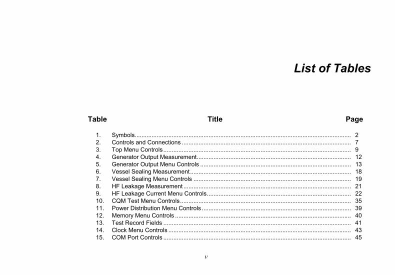
List of Tables
Table Title Page
1. Symbols ................................................................................................................................. 2 2. Controls and Connections ..................................................................................................... 7 3. Top Menu Controls ................................................................................................................ 9 4. Generator Output Measurement ............................................................................................ 12 5. Generator Output Menu Controls .......................................................................................... 13 6. Vessel Sealing Measurement ................................................................................................ 18 7. Vessel Sealing Menu Controls .............................................................................................. 19 8. HF Leakage Measurement .................................................................................................... 21 9. HF Leakage Current Menu Controls ...................................................................................... 22 10. CQM Test Menu Controls ...................................................................................................... 35 11. Power Distribution Menu Controls ......................................................................................... 39 12. Memory Menu Controls ......................................................................................................... 40 13. Test Record Fields ................................................................................................................ 41 14. Clock Menu Controls ............................................................................................................. 43 15. COM Port Controls ................................................................................................................ 45
QA-ES III Users Manual
vi
16. Bluetooth Settings ................................................................................................................. 47 17. Troubleshooting .................................................................................................................... 48 18. Replaceable Parts ................................................................................................................ 49 19. List of Accessories ................................................................................................................ 50
vii
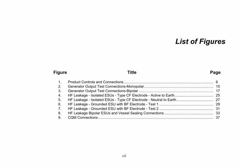
List of Figures
Figure Title Page
1. Product Controls and Connections ........................................................................................ 6 2. Generator Output Test Connections-Monopolar .................................................................... 15 3. Generator Output Test Connections-Bipolar ......................................................................... 17 4. HF Leakage - Isolated ESUs - Type CF Electrode - Active to Earth ...................................... 25 5. HF Leakage - Isolated ESUs - Type CF Electrode - Neutral to Earth .................................... 27 6. HF Leakage - Grounded ESU with BF Electrode - Test 1 ..................................................... 29 7. HF Leakage - Grounded ESU with BF Electrode - Test 2 ..................................................... 31 8. HF Leakage Bipolar ESUs and Vessel Sealing Connections ................................................ 33 9. CQM Connections ................................................................................................................. 37

QA-ES III Users Manual
viii
1
Introduction The QA-ES III (or the Product) measures the performance of high frequency Electrosurgery Units (ESU) and saves test records that you can transmit to a computer (PC). You can control the Product remotely from the Fluke Ansur software program.
The Product makes these measurements and tests:
• Generator output:
ο Power, RMS
ο Current, RMS
ο Voltage, peak to peak
ο Crest Factor
• Vessel Sealing Loop Current
• HF Leakage Current in various configurations
• Contact Quality Monitor (CQM) test
• Power Distribution test automatically makes a series of Generator Output measurements at various loads
Intended Use The Product is a precision instrument for use in performing tests on high-frequency electrosurgical units in accordance with national and international standards. It is for use by trained service technicians. Tests include automatic power distribution measurement, crest factor measurement, RF leakage measurement, CQM (contact quality monitor) test. The Product will be used in hospitals, clinical engineering departments, independent service organizations, and at ESU OEMs. The Product will not be used in patient rooms while a patient is present.
QA-ES III Users Manual
2
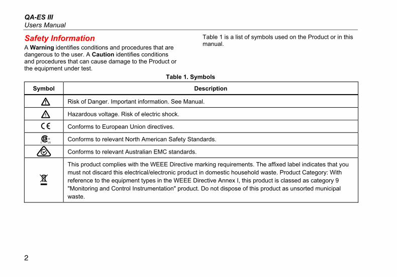
Safety Information A Warning identifies conditions and procedures that are dangerous to the user. A Caution identifies conditions and procedures that can cause damage to the Product or the equipment under test.
Table 1 is a list of symbols used on the Product or in this manual.
Table 1. Symbols
Symbol Description
W Risk of Danger. Important information. See Manual.
X Hazardous voltage. Risk of electric shock.
P Conforms to European Union directives.
) Conforms to relevant North American Safety Standards.
Conforms to relevant Australian EMC standards.
~
This product complies with the WEEE Directive marking requirements. The affixed label indicates that you must not discard this electrical/electronic product in domestic household waste. Product Category: With reference to the equipment types in the WEEE Directive Annex I, this product is classed as category 9 "Monitoring and Control Instrumentation" product. Do not dispose of this product as unsorted municipal waste.
Electrosurgery Analyzer Safety Information
3
XW Warning
To prevent possible electrical shock, fire, or personal injury, follow these guidelines:
• Read all safety information before you use the Product.
• Use the Product only as specified, or the protection supplied by the Product can be compromised.
• Limit operation to the specified measurement category, voltage, or amperage ratings.
• Use the correct terminals, function, and range for measurements.
• Carefully read all instructions.
• Do not touch voltages >30 V ac rms, 42 V ac peak, or 60 V dc.
• Do not use the Product around explosive gas, vapor, or in damp or wet environments.
• Do not use the Product if it operates incorrectly.
• Examine the case before you use the Product. Look for cracks or missing plastic. Carefully look at the insulation around the terminals.
• Do not use test leads if they are damaged. Examine the test leads for damaged insulation, exposed metal, or if the wear indicator shows. Check test lead continuity.
• Use this Product indoors only.
• Use only the mains power cord and connector approved for the voltage and plug configuration in your country and rated for the Product.
• Make sure the ground conductor in the mains power cord is connected to a protective earth ground. Disruption of the protective earth could put voltage on the chassis that could cause death.
QA-ES III Users Manual
4
• Replace the mains power cord if the insulation is damaged or if the insulation shows signs of wear.
• Use only current probes, test leads, and adapters supplied with the Product.
• Connect the common test lead before the live test lead and remove the live test lead before the common test lead.
• Only use probes, test leads, and accessories that have the same measurement category, voltage, and amperage ratings as the Product.
• Remove all probes, test leads, and accessories that are not necessary for the measurement.
• Do not connect measurement inputs directly to mains.
• Do not use test leads if they are damaged. Examine the test leads for damaged insulation and measure a known voltage.
• Disable the Product if it is damaged.
• Do not use the Product if it is damaged.
Terminology The Product uses the following terminology as described in IEC 60601-2-2:
• HF – high frequency surgical signals also called RF (radio frequency).
• Neutral Electrode also called Dispersive Electrode.
• Contact Quality Monitor (CQM) also called Return Electrode Monitor (REM trademarked by Covidien) or Return Electrode Current Monitor (RECM).
Electrosurgery Analyzer Unpack the Product
5
Unpack the Product Carefully unpack all items from the box and check that you have the following items:
• QA-ES III Electrosurgery Analyzer
• Users Manual on CD
• Getting Started Manual
• Alligator clips, black and red
• Dispersive safety lead
• CQM safety lead
• Jumper safety lead (Shorting Leads)
• 40 inch stackable/retractable safety leads, black, red (2), blue, yellow, and green
• 20 inch stackable/retractable safety leads, black and red
• Multi-stacking 4 mm banana plug patch cord, black
• RECM Alarm Disabling Lead
• Bipolar Activation Lead
• USB cable
• Ansur Software CD ROM
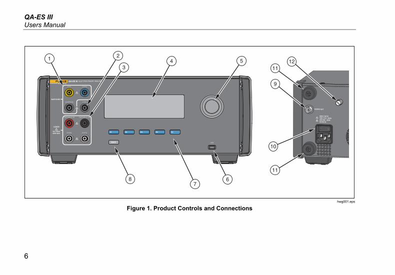
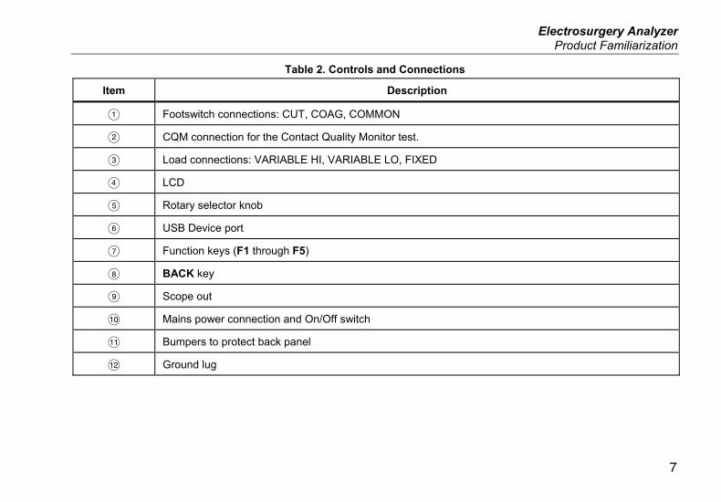
Product Familiarization Figure 1 and Table 2 describe the controls and connections on the product.
QA-ES III Users Manual
6
ELECTROSURGERY ANALYZERQA-ES III
CUT COAG
COMMON CQM
VARIABLE HI VARIABLE LO
FIXED FIXED F1
BACK USB
F2 F3 F4 F5
SWITCHES
LOADS
5kV PEAK400W MAX
1 24 5
67
8
3
9
10
11
1112
hwg001.eps
Figure 1. Product Controls and Connections
Electrosurgery Analyzer Product Familiarization
7
Table 2. Controls and Connections
Item Description
Footswitch connections: CUT, COAG, COMMON
CQM connection for the Contact Quality Monitor test.
Load connections: VARIABLE HI, VARIABLE LO, FIXED
LCD
Rotary selector knob
USB Device port
Function keys (F1 through F5)
BACK key
Scope out
Mains power connection and On/Off switch
Bumpers to protect back panel
Ground lug
QA-ES III Users Manual
8
Turn on the Product Before you turn on the Product, check for damage or wear. Check for adequate ventilation. The Product requires a clear area of 10 cm (4 in) at the rear panel and all vent openings.
Connect the power cord to Mains power and push the power switch. The start-up sequence begins.
During the start-up sequence, a screen shows the firmware version for reference. You can use the start-up sequence to update the firmware.
After the start-up sequence, the Product starts the application. When the Top Menu screen shows, the Product is ready for use.
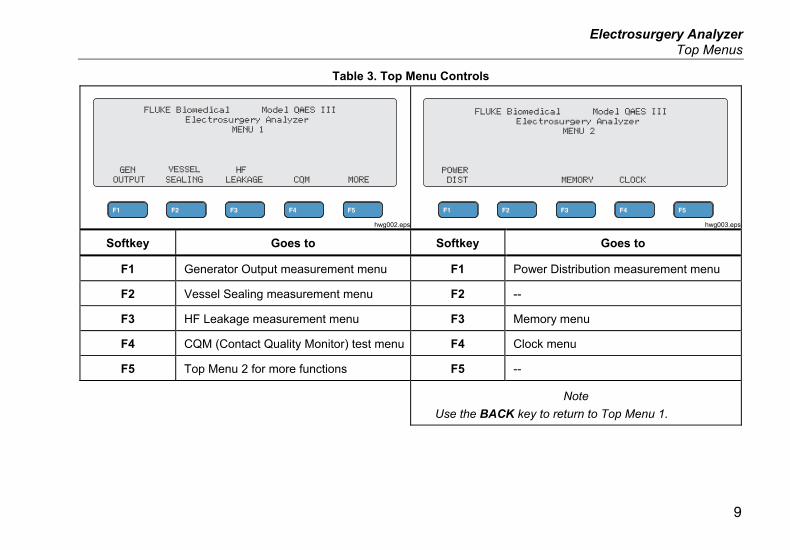
Top Menus The Top Menus 1 and 2 have sub-menus to make measurements, set up the instrument, and maintain memory. Use the controls and softkeys to make selections from the menus. Table 3 describes the Top Menu controls.
See the Product Operation section for a description of each test menu.
Electrosurgery Analyzer Top Menus
9
Table 3. Top Menu Controls
hwg002.eps
hwg003.eps
Softkey Goes to Softkey Goes to
F1 Generator Output measurement menu F1 Power Distribution measurement menu
F2 Vessel Sealing measurement menu F2 --
F3 HF Leakage measurement menu F3 Memory menu
F4 CQM (Contact Quality Monitor) test menu F4 Clock menu
F5 Top Menu 2 for more functions F5 --
Note
Use the BACK key to return to Top Menu 1.
QA-ES III Users Manual
10
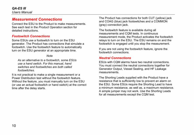
Measurement Connections Connect the ESU to the Product to make measurements. See each test in the Product Operation section for detailed instructions.
Footswitch Connections Some ESUs use a footswitch to turn on the ESU generator. The Product has connections that simulate a footswitch. Use the footswitch feature to automatically turn on the ESU generator at an appropriate time.
Note
As an alternative to a footswitch, some ESUs use a hand switch. For this manual, hand switches and footswitches are both called footswitches.
It is not practical to make a single measurement or a Power Distribution test without the footswitch feature. Without the feature, you must manually turn on the ESU (or use an actual footswitch or hand switch) at the correct time after the delay starts.
The Product has connections for both CUT (yellow) jack and COAG (blue) jack footswitches and a COMMON (gray) connection jack.
The footswitch feature is available during all measurements and CQM tests. In continuous measurement mode, the Product activates the footswitch relays to turn on the ESU. The ESU remains on and the footswitch is engaged until you stop the measurement.
If you are not using the footswitch feature, ignore the footswitch connections.
Neutral Connections ESUs with CQM alarms have two neutral connections. You must connect the neutral connections together for Generator Output, Vessel Sealing, and HF Leakage measurements.
The Shorting Leads supplied with the Product have a resistance that is sufficiently low to prevent an alarm on the ESU. Some ESUs require the Shorting Lead to have a minimum resistance, as well as, a maximum resistance. A simple jumper may not work. Use the Shorting Leads for all measurements except the CQM test.
Electrosurgery Analyzer Product Operation
11
Product Operation
XW Warning
To prevent possible electrical shock, fire, or personal injury, follow these guidelines:
• Do not touch exposed metal on banana plugs, they can have voltages that could cause death.
• Remove circuit power before you connect the Product in the circuit when you measure current. Connect the Product in series with the circuit.
• Connect an approved three-conductor mains power cord to a grounded power outlet.
• Do not put the Product where access to the mains power cord is blocked.
• Make sure that the Product is grounded before use.
• Do not put metal objects into connectors.
• Do not use an extension cord or adapter plug.
• Make sure that the space around the Product meets minimum requirements.
• Do not use the Analyzer in CAT II, III, or IV environments.
• Retractable end of test leads are for use on ESU only.
• No probes or accessories supplied with the Analyzer are intended for handheld use. Setup and stand clear when activating the ESU with the footswitch.
Generator Output During the Generator Output test, the Product connects the variable load resistance from the VARIABLE HI (red) active electrode to the VARIABLE LO (black) neutral electrode. The test measures the ESU output across that load and shows the measured Generator Output:
• Power (W)
• Current (mA)
• VoltagePkPk (V)
• Crest Factor
QA-ES III Users Manual
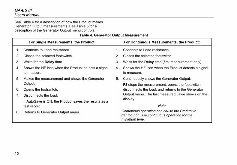
12
See Table 4 for a description of how the Product makes Generator Output measurements. See Table 5 for a description of the Generator Output menu controls.
Table 4. Generator Output Measurement
For Single Measurements, the Product: For Continuous Measurements, the Product:
1. Connects to Load resistance.
2. Closes the selected footswitch.
3. Waits for the Delay time.
4. Shows the HF icon when the Product detects a signal to measure.
5. Makes the measurement and shows the Generator Output.
6. Opens the footswitch.
7. Disconnects the load.
If AutoSave is ON, the Product saves the results as a test record.
8. Returns to Generator Output menu.
1. Connects to Load resistance.
2. Closes the selected footswitch.
3. Waits for the Delay time (first measurement only)
4. Shows the HF icon when the Product detects a signal to measure.
5. Continuously shows the Generator Output.
F3 stops the measurement, opens the footswitch, disconnects the load, and returns to the Generator Output menu. The last measured value shows on the display.
Note
Continuous operation can cause the Product to get too hot. Use continuous operation for the minimum time.
Electrosurgery Analyzer Product Operation
13
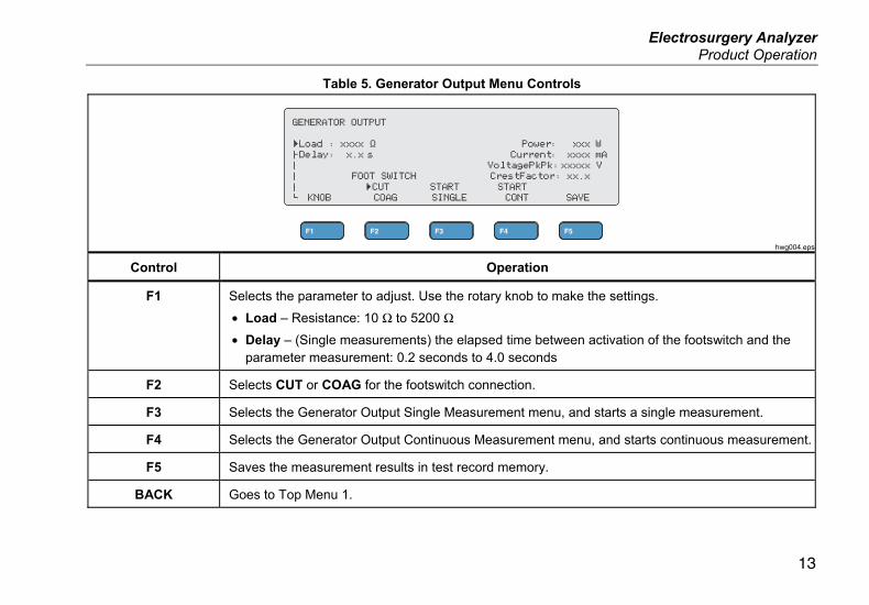
Table 5. Generator Output Menu Controls
hwg004.eps
Control Operation
F1 Selects the parameter to adjust. Use the rotary knob to make the settings.
• Load – Resistance: 10 Ω to 5200 Ω
• Delay – (Single measurements) the elapsed time between activation of the footswitch and the parameter measurement: 0.2 seconds to 4.0 seconds
F2 Selects CUT or COAG for the footswitch connection.
F3 Selects the Generator Output Single Measurement menu, and starts a single measurement.
F4 Selects the Generator Output Continuous Measurement menu, and starts continuous measurement.
F5 Saves the measurement results in test record memory.
BACK Goes to Top Menu 1.

QA-ES III Users Manual
14
Generator Output Test To do a Generator Output test:
1. Push F1 from the Top Menu 1.
2. Use the rotary knob to set the Load resistance.
3. If using the footswitch, push F1 and use the rotary knob to set the Delay.
4. Make the test connections, see Generator Output Test Connections.
5. If using the footswitch, select CUT or COAG.
6. Push F3 to start a single measurement or push F4 to start continuous measurement.
7. Push F3 to stop the measurement.
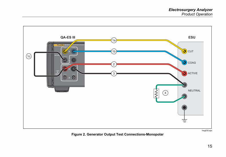
Generator Output Test Connections - Monopolar Figure 2 shows the monopolar test connections between the ESU and the Product. Make these connections to do a Generator Output or Power Distribution test.
1. If using the footswitch, make these connections:
a. Connect the ESU cut switch to the CUT (yellow) jack on the Product.
b. Connect the ESU coag switch to the COAG (blue) jack on the Product.
c. Use a stackable jumper to connect the footswitch COMMON (gray) jack to the VARIABLE HI jack (red).
2. Connect the ESU active electrode to the VARIABLE HI (red) active electrode on the Product.
3. Use a stackable connector to connect one of the ESU neutral electrodes to the VARIABLE LO (black) jack on the Product.
4. Connect the Shorting Leads between the neutral connections on the ESU.
Electrosurgery Analyzer Product Operation
15
ELECTROSURGERY ANALYZERQA-ES III
CUT COAG
COMMON CQM
VARIABLE HI VARIABLE LO
FIXED FIXED
SWITCHES
LOADS
5kV PEAK400W MAX
COAG
ACTIVE
NEUTRAL
ESUQA-ES III
1c
1a
1b
4
2
3
CUT
hwg030.eps
Figure 2. Generator Output Test Connections-Monopolar
QA-ES III Users Manual
16
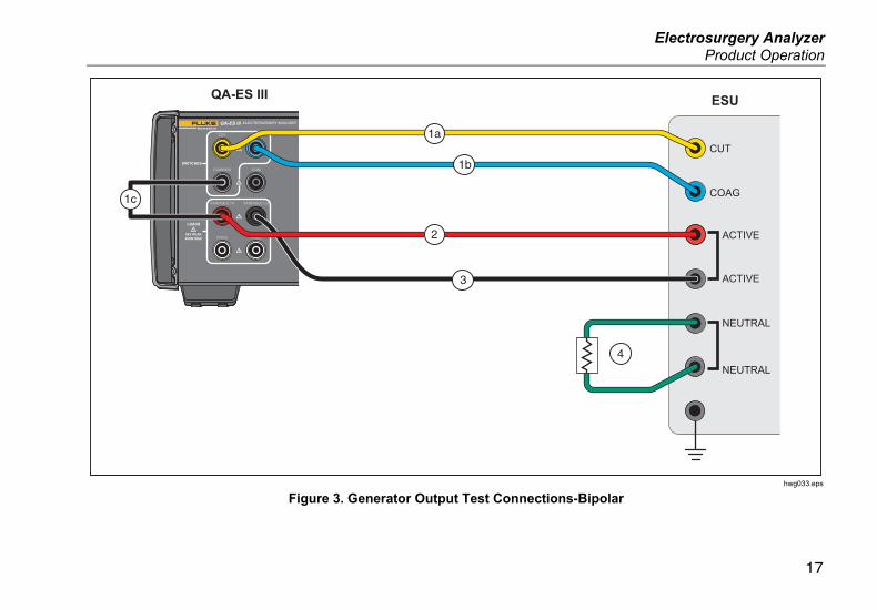
Generator Output Test Connections - Bipolar Figure 3 shows the bipolar test connections between the ESU and the Product. Make these connections to do a Generator Output or Power Distribution test.
1. If using the footswitch, make these connections:
a. Connect the ESU cut switch to the CUT (yellow) jack on the Product.
b. Connect the ESU coag switch to the COAG (blue) jack on the Product.
c. Use a stackable jumper to connect the footswitch COMMON (gray) jack to the VARIABLE HI jack (red).
2. Connect one ESU Bipolar Active Electrode to the VARIABLE HI (red) active electrode on the Product.
3. Connect the other ESU Bipolar Active Electrode to the VARIABLE LO (black) active electrode on the Product.
4. Connect the Shorting Leads between the neutral connections on the ESU.
Electrosurgery Analyzer Product Operation
17
ELECTROSURGERY ANALYZERQA-ES III
CUT COAG
COMMON CQM
VARIABLE HI VARIABLE LO
FIXED FIXED
SWITCHES
LOADS
5kV PEAK400W MAX
COAG
ACTIVE
ACTIVE
NEUTRAL
NEUTRAL
ESUQA-ES III
1a
1bCUT
3
4
2
1c
hwg033.eps
Figure 3. Generator Output Test Connections-Bipolar
QA-ES III Users Manual
18
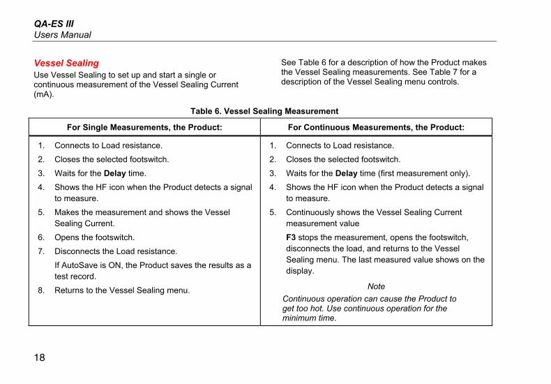
Vessel Sealing Use Vessel Sealing to set up and start a single or continuous measurement of the Vessel Sealing Current (mA).
See Table 6 for a description of how the Product makes the Vessel Sealing measurements. See Table 7 for a description of the Vessel Sealing menu controls.
Table 6. Vessel Sealing Measurement
For Single Measurements, the Product: For Continuous Measurements, the Product:
1. Connects to Load resistance.
2. Closes the selected footswitch.
3. Waits for the Delay time.
4. Shows the HF icon when the Product detects a signal to measure.
5. Makes the measurement and shows the Vessel Sealing Current.
6. Opens the footswitch.
7. Disconnects the Load resistance.
If AutoSave is ON, the Product saves the results as a test record.
8. Returns to the Vessel Sealing menu.
1. Connects to Load resistance.
2. Closes the selected footswitch.
3. Waits for the Delay time (first measurement only).
4. Shows the HF icon when the Product detects a signal to measure.
5. Continuously shows the Vessel Sealing Current measurement value
F3 stops the measurement, opens the footswitch, disconnects the load, and returns to the Vessel Sealing menu. The last measured value shows on the display.
Note
Continuous operation can cause the Product to get too hot. Use continuous operation for the minimum time.
Electrosurgery Analyzer Product Operation
19
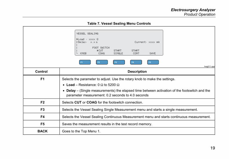
Table 7. Vessel Sealing Menu Controls
hwg011.eps
Control Description
F1 Selects the parameter to adjust. Use the rotary knob to make the settings.
• Load – Resistance: 0 Ω to 5200 Ω
• Delay – (Single measurements) the elapsed time between activation of the footswitch and the parameter measurement: 0.2 seconds to 4.0 seconds
F2 Selects CUT or COAG for the footswitch connection.
F3 Selects the Vessel Sealing Single Measurement menu and starts a single measurement.
F4 Selects the Vessel Sealing Continuous Measurement menu and starts continuous measurement.
F5 Saves the measurement results in the test record memory.
BACK Goes to the Top Menu 1.
QA-ES III Users Manual
20
Vessel Sealing Test To do a Vessel Sealing test:
1. Push F2 from the Top Menu 1.
2. Use the rotary knob to set the Load resistance.
3. If using the footswitch, push F1 and use the rotary knob to set the Delay for the footswitch.
4. Make the Vessel Sealing connections, see Vessel Sealing Connections.
5. If using the footswitch, select CUT or COAG.
6. Push F3 to start a single measurement or push F4 to start continuous measurement.
7. Push F3 to stop the measurement and return to the menu.
Vessel Sealing Connections The Vessel Sealing Test connection is the same as the bipolar connection. See Figure 3 and Generator Output Test Connections - Bipolar.
HF Leakage For all HF Leakage measurements, the Product places a 200 Ω load resistance from the VARIABLE HI (red) active jack to the VARIABLE LO (black) neutral jack, and measures the Leakage Current (mA) through that load.
Some measurements also use the fixed 200 Ω load at the (white) 200 Ω jacks. The bipolar leakage measurement uses an additional internal 200 Ω load to earth that gets switched into the circuit.
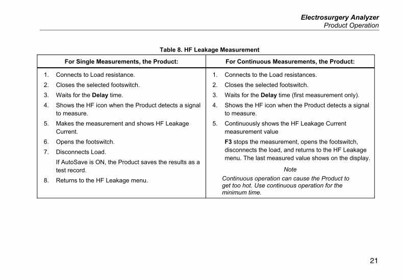
See Table 8 for a description of how the Product makes the HF Leakage measurements. See Table 9 for a description of the HF Leakage menu controls.
Electrosurgery Analyzer Product Operation
21
Table 8. HF Leakage Measurement
For Single Measurements, the Product: For Continuous Measurements, the Product:
1. Connects to Load resistance.
2. Closes the selected footswitch.
3. Waits for the Delay time.
4. Shows the HF icon when the Product detects a signal to measure.
5. Makes the measurement and shows HF Leakage Current.
6. Opens the footswitch.
7. Disconnects Load.
If AutoSave is ON, the Product saves the results as a test record.
8. Returns to the HF Leakage menu.
1. Connects to the Load resistances.
2. Closes the selected footswitch.
3. Waits for the Delay time (first measurement only).
4. Shows the HF icon when the Product detects a signal to measure.
5. Continuously shows the HF Leakage Current measurement value
F3 stops the measurement, opens the footswitch, disconnects the load, and returns to the HF Leakage menu. The last measured value shows on the display.
Note
Continuous operation can cause the Product to get too hot. Use continuous operation for the minimum time.
QA-ES III Users Manual
22
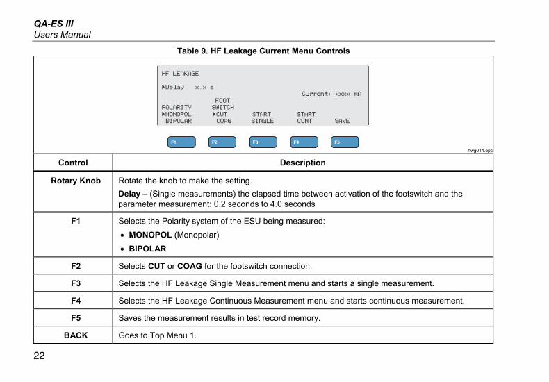
Table 9. HF Leakage Current Menu Controls
hwg014.eps
Control Description
Rotary Knob Rotate the knob to make the setting.
Delay – (Single measurements) the elapsed time between activation of the footswitch and the parameter measurement: 0.2 seconds to 4.0 seconds
F1 Selects the Polarity system of the ESU being measured:
• MONOPOL (Monopolar)
• BIPOLAR
F2 Selects CUT or COAG for the footswitch connection.
F3 Selects the HF Leakage Single Measurement menu and starts a single measurement.
F4 Selects the HF Leakage Continuous Measurement menu and starts continuous measurement.
F5 Saves the measurement results in test record memory.
BACK Goes to Top Menu 1.
Electrosurgery Analyzer Product Operation
23
HF Leakage Test To do a HF Leakage test:
1. Push F3 from the Top Menu 1.
2. If using the footswitch, use the rotary knob to set the Delay for the footswitch.
3. Make the appropriate connections, see HF Leakage Test Connections
4. To use the footswitch, set CUT or COAG.
5. Push F3 to start a single measurement or push F4 to start continuous measurement.
6. Push F3 to stop the measurement and return to the menu.
HF Leakage Test Connections This section tells how to connect the ESU to the Product to make HF Leakage measurements. The HF Leakage measurement connections are in accordance with the international standard: IEC 60601-2-2, Edition 5.0, 2009-02. Medical electrical equipment – Part 2-2: Particular requirements for the basic safety and essential performance of high frequency surgical equipment and high frequency surgical accessories.
QA-ES III Users Manual
24
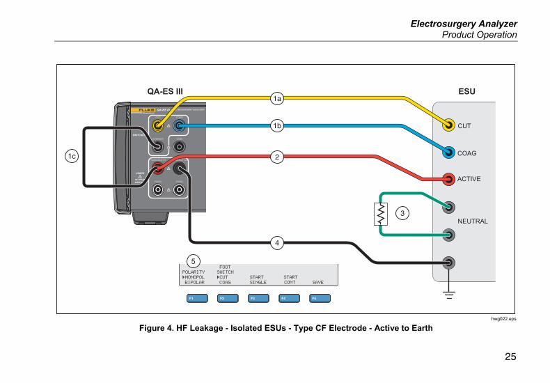
HF Leakage - Isolated ESUs - Type CF Electrode (Active to Earth)
Section 201.8.7.3.101 a) 2), figure 201.106 (Active Electrode to Earth) Figure 4 shows how to connect the ESU to the Product to make an HF Leakage test for Isolated ESUs with Type CF electrodes. For this test, the Product measures the current through the VARIABLE HI (red) active jack to the VARIABLE LO (black) neutral jack.
To test active electrode to earth
1. If using the footswitch, make these connections:
a. Connect the ESU cut switch to the CUT (yellow) jack on the Product.
b. Connect the ESU coag switch to the COAG (blue) jack on the Product.
c. Use a stackable jumper to connect the footswitch COMMON (gray) jack to the VARIABLE HI (red) active jack.
2. Connect the ESU active electrode stacked onto the VARIABLE HI (red) active jack.
3. Connect the Shorting Leads between the two ESU neutral connections.
4. Connect an earth contact on the ESU to the VARIABLE LO (black) neutral jack on the Product.
5. Set POLARITY to MONOPOL (Monopolar).
Electrosurgery Analyzer Product Operation
25
ELECTROSURGERY ANALYZERQA-ES III
CUT COAG
COMMON CQM
VARIABLE HI VARIABLE LO
FIXED FIXED
SWITCHES
LOADS
5kV PEAK400W MAX
COAG
ACTIVE
NEUTRAL
ESUQA-ES III
1c
1a
1b
2
5
4
3
CUT
hwg022.eps
Figure 4. HF Leakage - Isolated ESUs - Type CF Electrode - Active to Earth
QA-ES III Users Manual
26
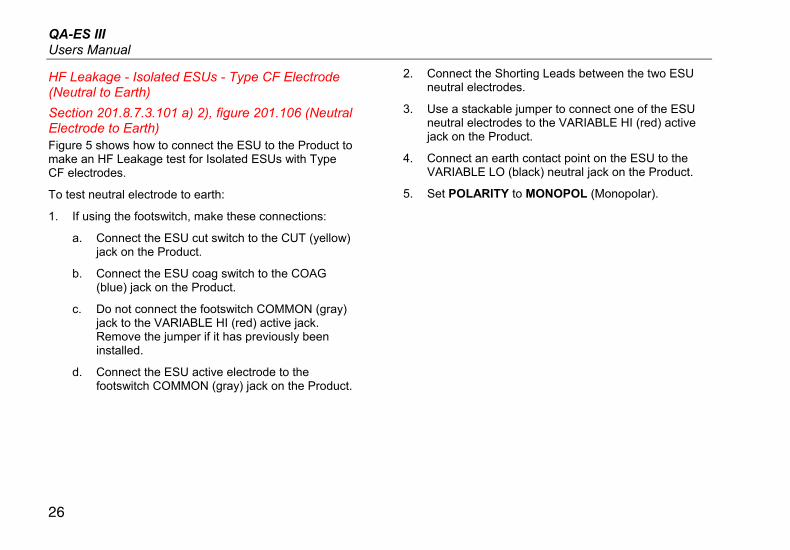
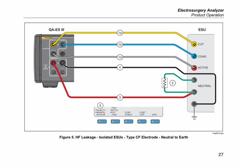
HF Leakage - Isolated ESUs - Type CF Electrode (Neutral to Earth)
Section 201.8.7.3.101 a) 2), figure 201.106 (Neutral Electrode to Earth) Figure 5 shows how to connect the ESU to the Product to make an HF Leakage test for Isolated ESUs with Type CF electrodes.
To test neutral electrode to earth:
1. If using the footswitch, make these connections:
a. Connect the ESU cut switch to the CUT (yellow) jack on the Product.
b. Connect the ESU coag switch to the COAG (blue) jack on the Product.
c. Do not connect the footswitch COMMON (gray) jack to the VARIABLE HI (red) active jack. Remove the jumper if it has previously been installed.
d. Connect the ESU active electrode to the footswitch COMMON (gray) jack on the Product.
2. Connect the Shorting Leads between the two ESU neutral electrodes.
3. Use a stackable jumper to connect one of the ESU neutral electrodes to the VARIABLE HI (red) active jack on the Product.
4. Connect an earth contact point on the ESU to the VARIABLE LO (black) neutral jack on the Product.
5. Set POLARITY to MONOPOL (Monopolar).
Electrosurgery Analyzer Product Operation
27
ELECTROSURGERY ANALYZERQA-ES III
CUT COAG
COMMON CQM
VARIABLE HI VARIABLE LO
FIXED FIXED
SWITCHES
LOADS
5kV PEAK400W MAX
COAG
CUT
ACTIVE
NEUTRAL
ESUQA-ES III1a
1b
1d
5
4
3
2
hwg023.eps
Figure 5. HF Leakage - Isolated ESUs - Type CF Electrode - Neutral to Earth
QA-ES III Users Manual
28
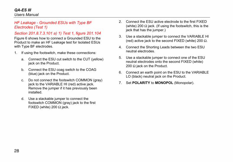
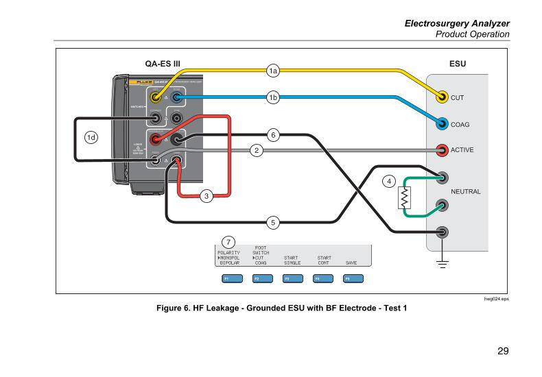
HF Leakage - Grounded ESUs with Type BF Electrodes (Test 1)
Section 201.8.7.3.101 a) 1) Test 1, figure 201.104 Figure 6 shows how to connect a Grounded ESU to the Product to make an HF Leakage test for Isolated ESUs with Type BF electrodes.
1. If using the footswitch, make these connections:
a. Connect the ESU cut switch to the CUT (yellow) jack on the Product.
b. Connect the ESU coag switch to the COAG (blue) jack on the Product.
c. Do not connect the footswitch COMMON (gray) jack to the VARIABLE HI (red) active jack. Remove the jumper if it has previously been installed.
d. Use a stackable jumper to connect the footswitch COMMON (gray) jack to the first FIXED (white) 200 Ω jack.
2. Connect the ESU active electrode to the first FIXED (white) 200 Ω jack. (If using the footswitch, this is the jack that has the jumper.)
3. Use a stackable jumper to connect the VARIABLE HI (red) active jack to the second FIXED (white) 200 Ω.
4. Connect the Shorting Leads between the two ESU neutral electrodes.
5. Use a stackable jumper to connect one of the ESU neutral electrodes onto the second FIXED (white) 200 Ω jack on the Product.
6. Connect an earth point on the ESU to the VARIABLE LO (black) neutral jack on the Product.
7. Set POLARITY to MONOPOL (Monopolar).
Electrosurgery Analyzer Product Operation
29
ELECTROSURGERY ANALYZERQA-ES III
CUT COAG
COMMON CQM
VARIABLE HI VARIABLE LO
FIXED FIXED
SWITCHES
LOADS
5kV PEAK400W MAX
COAG
ACTIVE
NEUTRAL
ESUQA-ES III
CUT
1a
1b
2
7
5
4
1d 6
3
hwg024.eps
Figure 6. HF Leakage - Grounded ESU with BF Electrode - Test 1
QA-ES III Users Manual
30
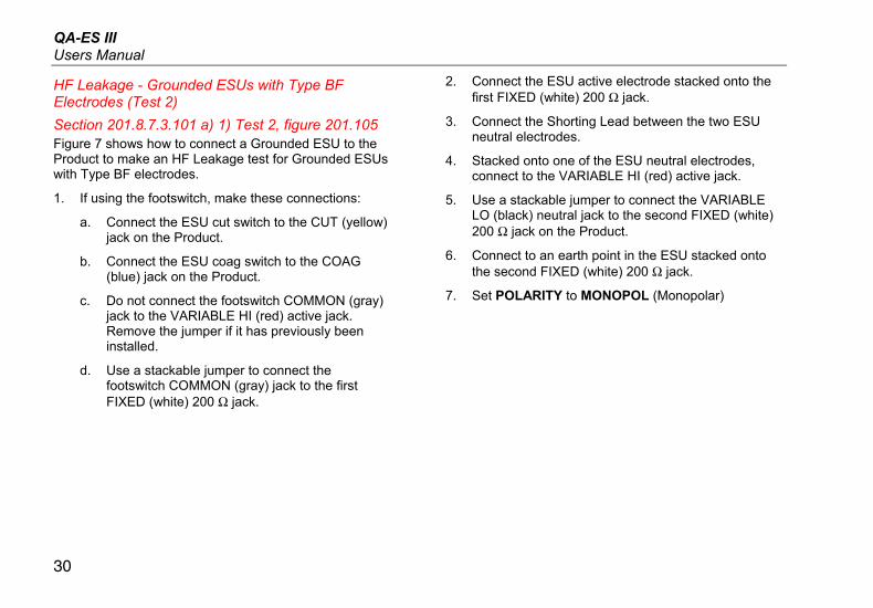
HF Leakage - Grounded ESUs with Type BF Electrodes (Test 2)
Section 201.8.7.3.101 a) 1) Test 2, figure 201.105 Figure 7 shows how to connect a Grounded ESU to the Product to make an HF Leakage test for Grounded ESUs with Type BF electrodes.
1. If using the footswitch, make these connections:
a. Connect the ESU cut switch to the CUT (yellow) jack on the Product.
b. Connect the ESU coag switch to the COAG (blue) jack on the Product.
c. Do not connect the footswitch COMMON (gray) jack to the VARIABLE HI (red) active jack. Remove the jumper if it has previously been installed.
d. Use a stackable jumper to connect the footswitch COMMON (gray) jack to the first FIXED (white) 200 Ω jack.
2. Connect the ESU active electrode stacked onto the first FIXED (white) 200 Ω jack.
3. Connect the Shorting Lead between the two ESU neutral electrodes.
4. Stacked onto one of the ESU neutral electrodes, connect to the VARIABLE HI (red) active jack.
5. Use a stackable jumper to connect the VARIABLE LO (black) neutral jack to the second FIXED (white) 200 Ω jack on the Product.
6. Connect to an earth point in the ESU stacked onto the second FIXED (white) 200 Ω jack.
7. Set POLARITY to MONOPOL (Monopolar)
Electrosurgery Analyzer Product Operation
31
ELECTROSURGERY ANALYZERQA-ES III
CUT COAG
COMMON CQM
VARIABLE HI VARIABLE LO
FIXED FIXED
SWITCHES
LOADS
5kV PEAK400W MAX
COAG
ACTIVE
NEUTRAL
ESUQA-ES III
CUT
1a
1b
2
7
3
1d
4
6
5
hwg025.eps
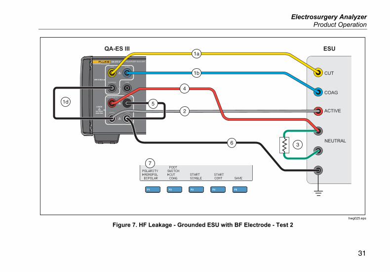
Figure 7. HF Leakage - Grounded ESU with BF Electrode - Test 2
QA-ES III Users Manual
32
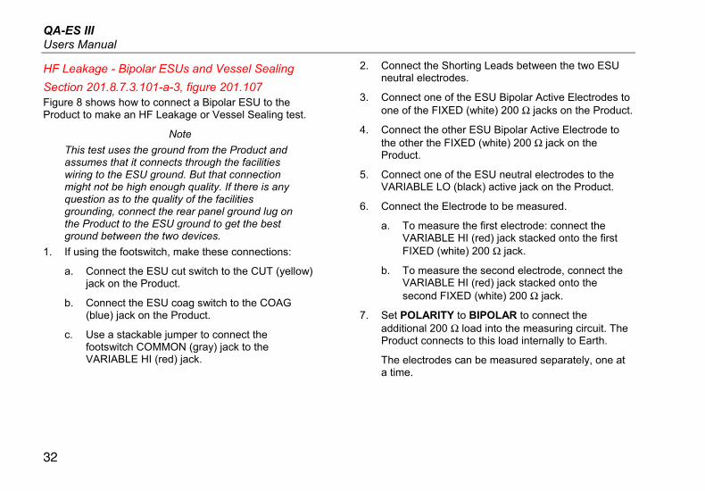
HF Leakage - Bipolar ESUs and Vessel Sealing
Section 201.8.7.3.101-a-3, figure 201.107 Figure 8 shows how to connect a Bipolar ESU to the Product to make an HF Leakage or Vessel Sealing test.
Note
This test uses the ground from the Product and assumes that it connects through the facilities wiring to the ESU ground. But that connection might not be high enough quality. If there is any question as to the quality of the facilities grounding, connect the rear panel ground lug on the Product to the ESU ground to get the best ground between the two devices.
1. If using the footswitch, make these connections:
a. Connect the ESU cut switch to the CUT (yellow) jack on the Product.
b. Connect the ESU coag switch to the COAG (blue) jack on the Product.
c. Use a stackable jumper to connect the footswitch COMMON (gray) jack to the VARIABLE HI (red) jack.
2. Connect the Shorting Leads between the two ESU neutral electrodes.
3. Connect one of the ESU Bipolar Active Electrodes to one of the FIXED (white) 200 Ω jacks on the Product.
4. Connect the other ESU Bipolar Active Electrode to the other the FIXED (white) 200 Ω jack on the Product.
5. Connect one of the ESU neutral electrodes to the VARIABLE LO (black) active jack on the Product.
6. Connect the Electrode to be measured.
a. To measure the first electrode: connect the VARIABLE HI (red) jack stacked onto the first FIXED (white) 200 Ω jack.
b. To measure the second electrode, connect the VARIABLE HI (red) jack stacked onto the second FIXED (white) 200 Ω jack.
7. Set POLARITY to BIPOLAR to connect the additional 200 Ω load into the measuring circuit. The Product connects to this load internally to Earth.
The electrodes can be measured separately, one at a time.
Electrosurgery Analyzer Product Operation
33
ELECTROSURGERY ANALYZERQA-ES III
CUT COAG
COMMON CQM
VARIABLE HI VARIABLE LO
FIXED FIXED
SWITCHES
LOADS
5kV PEAK400W MAX
COAG
ACTIVE
ACTIVE
NEUTRAL
ESUQA-ES III
CUT1a
1b
7
2
c
NEUTRAL
3
b 4
a6
5
hwg026.eps
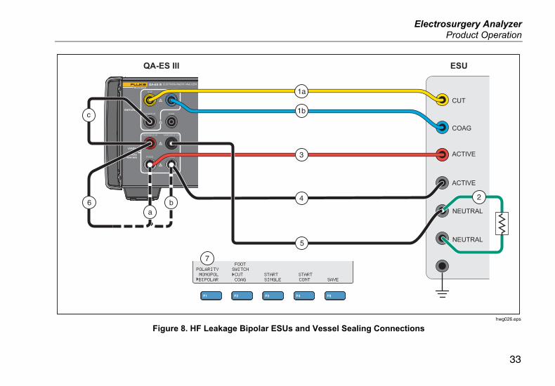
Figure 8. HF Leakage Bipolar ESUs and Vessel Sealing Connections
QA-ES III Users Manual
34
CQM Test The CQM test places the variable test resistance from the CQM (gray) jack to the VARIABLE LO (black) jack.
The ESU has an alarm that monitors contact between the two neutral electrode connections on the ESU. Use the CQM menu to test the ESU alarm.
For the CQM test, the Product puts an adjustable test resistance from the CQM (gray) jack to the VARIABLE LO (black) jack. Start the test with a small resistance and increase it until the alarm sounds on the ESU. The test result is the resistance that is just large enough to cause the ESU to alarm.
The resistance is always present across the jacks, as you make the adjustments.
The Product has an optional automatic mode for the CQM test. In automatic mode, the resistance starts at the current value, and increases by a 1 Ω step every given number of seconds (AutoTime). Stop the test when the device alarm sounds. You can start and stop the automatic mode.
When automatic mode is on, the rotary knob does not set the resistance or change the footswitch selection. You cannot save the test record during automatic mode. To exit automatic mode, push the F4 key.
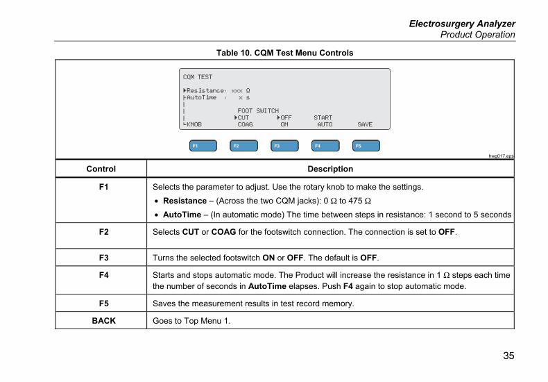
See Table 10 for a description of the CQM Test menu controls.
Electrosurgery Analyzer Product Operation
35
Table 10. CQM Test Menu Controls
hwg017.eps
Control Description
F1 Selects the parameter to adjust. Use the rotary knob to make the settings.
• Resistance – (Across the two CQM jacks): 0 Ω to 475 Ω
• AutoTime – (In automatic mode) The time between steps in resistance: 1 second to 5 seconds
F2 Selects CUT or COAG for the footswitch connection. The connection is set to OFF.
F3 Turns the selected footswitch ON or OFF. The default is OFF.
F4 Starts and stops automatic mode. The Product will increase the resistance in 1 Ω steps each time the number of seconds in AutoTime elapses. Push F4 again to stop automatic mode.
F5 Saves the measurement results in test record memory.
BACK Goes to Top Menu 1.
QA-ES III Users Manual
36
CQM Test Setup To do a CQM test:
1. Push F4 from the Top Menu 1.
2. Push F1 and use the rotary knob to set the Resistance and AutoTime.
3. Make the connections, see CQM Test Connections
4. Select CUT or COAG.
5. Push F4 to stop the automatic mode and return to the menu.
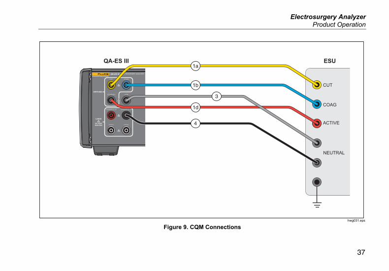
CQM Test Connections Figure 9 tells how to connect the ESU to the Product to make a CQM test.
1. If using the footswitch, make these connections:
a. Connect the ESU cut switch to the CUT (yellow) jack on the Product.
b. Connect the ESU coag switch to the COAG (blue) jack on the Product.
c. Do not connect the footswitch COMMON (gray) jack to the VARIABLE HI (red) active jack. Remove the jumper if it has previously been installed.
d. Connect the ESU active electrode to the footswitch COMMON (gray) jack on the Product.
2. If the Shorting Leads are present on the ESU, disconnect the Shorting Leads.
3. Connect one of the ESU neutral electrodes to the CQM (gray) jack on the Product.
4. Connect the other ESU neutral electrode to the VARIABLE LO (black) neutral jack on the Product.
The CQM test places the variable test resistance from the CQM (gray) jack to the neutral (black) jack.
Electrosurgery Analyzer Product Operation
37
ELECTROSURGERY ANALYZERQA-ES III
CUT COAG
COMMON CQM
VARIABLE HI VARIABLE LO
FIXED FIXED
SWITCHES
LOADS
5kV PEAK400W MAX
COAG
CUT
ACTIVE
NEUTRAL
ESUQA-ES III1a
1b
1d
4
3
hwg031.eps
Figure 9. CQM Connections

QA-ES III Users Manual
38
Power Distribution The Power Distribution test makes a series of Generator Output measurements at different loads (low to high).
Use the Power Distribution menu to make a series of Generator Output measurements. The measurement starts at the Start Load resistance and moves to the End Load resistance at intervals of the Step resistance.
For each measurement, the Product:
1. Connects to the Load resistance.
2. Closes the selected footswitch (CUT or COAG).
3. Waits for the Delay time.
4. Makes the measurement and shows the Generator Output:
• Load (Ω)
• Current (mA)
• Power (W)
• Voltage PkPk (V)
• Crest Factor
5. Opens the footswitch.
6. Disconnects Load.
If AutoSave is ON, the Product saves the results as a test record.
Table 11 describes the Power Distribution menu controls.
To do a Power Distribution test:
1. Push F4 from the Top Menu 1.
2. Push F1 and use the rotary knob to set the start resistance, end resistance, the step size, and the footswitch delay.
3. Select CUT or COAG for the footswitch.
4. Make the appropriate connections, see Generator Output Test Connections.
5. Push F3 to start the measurement.
Electrosurgery Analyzer Product Operation
39
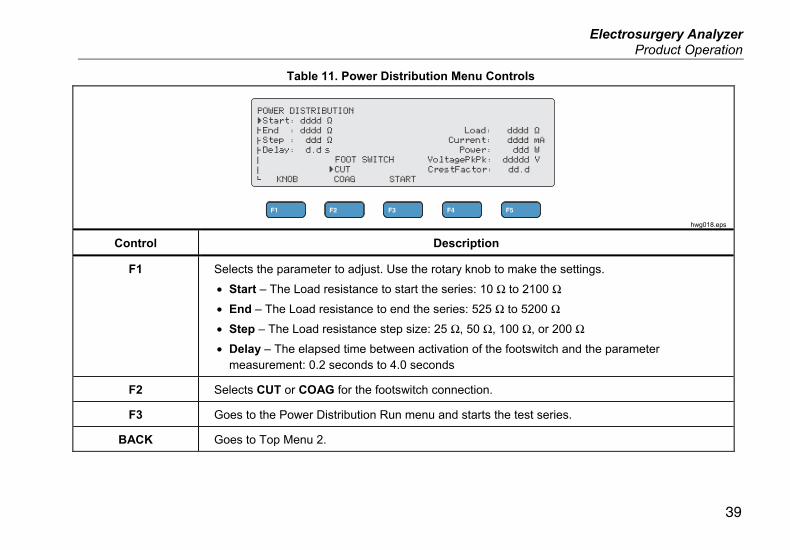
Table 11. Power Distribution Menu Controls
hwg018.eps
Control Description
F1 Selects the parameter to adjust. Use the rotary knob to make the settings.
• Start – The Load resistance to start the series: 10 Ω to 2100 Ω
• End – The Load resistance to end the series: 525 Ω to 5200 Ω
• Step – The Load resistance step size: 25 Ω, 50 Ω, 100 Ω, or 200 Ω
• Delay – The elapsed time between activation of the footswitch and the parameter measurement: 0.2 seconds to 4.0 seconds
F2 Selects CUT or COAG for the footswitch connection.
F3 Goes to the Power Distribution Run menu and starts the test series.
BACK Goes to Top Menu 2.
QA-ES III Users Manual
40
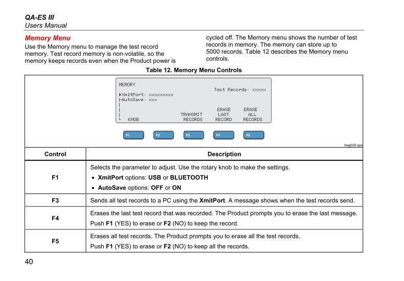
Memory Menu Use the Memory menu to manage the test record memory. Test record memory is non-volatile, so the memory keeps records even when the Product power is
cycled off. The Memory menu shows the number of test records in memory. The memory can store up to 5000 records. Table 12 describes the Memory menu controls.
Table 12. Memory Menu Controls
hwg020.eps
Control Description
F1
Selects the parameter to adjust. Use the rotary knob to make the settings.
• XmitPort options: USB or BLUETOOTH
• AutoSave options: OFF or ON
F3 Sends all test records to a PC using the XmitPort. A message shows when the test records send.
F4 Erases the last test record that was recorded. The Product prompts you to erase the last message.
Push F1 (YES) to erase or F2 (NO) to keep the record.
F5 Erases all test records. The Product prompts you to erase all the test records.
Push F1 (YES) to erase or F2 (NO) to keep all the records.
Electrosurgery Analyzer Product Operation
41
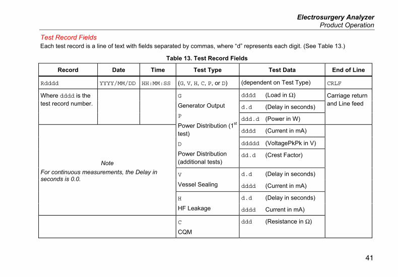
Test Record Fields Each test record is a line of text with fields separated by commas, where “d” represents each digit. (See Table 13.)
Table 13. Test Record Fields
Record Date Time Test Type Test Data End of Line
Rdddd YYYY/MM/DD HH:MM:SS (G, V, H, C, P, or D) (dependent on Test Type) CRLF
Where dddd is the test record number.
G
Generator Output
P
Power Distribution (1st test)
D
Power Distribution (additional tests)
dddd (Load in Ω) Carriage return and Line feed
d.d (Delay in seconds)
ddd.d (Power in W)
Note
For continuous measurements, the Delay in seconds is 0.0.
dddd (Current in mA)
ddddd (VoltagePkPk in V)
dd.d (Crest Factor)
V
Vessel Sealing
d.d (Delay in seconds)
dddd (Current in mA)
H
HF Leakage
d.d (Delay in seconds)
dddd Current in mA)
C
CQM
ddd (Resistance in Ω)
QA-ES III Users Manual
42
Example Test Records Generator Output
R0001,2015/07/04,12:31:34,G,0200,2.3,1234,3.5,213,0386,04316,01.4<CRLF>
Power Distribution
R0101,2015/08/17,15:22:06,P,100,4.0,150,1035,02156,01.4<CRLF>
R0102,2015/08/17,15:27:34,D,200,4.0,145,0962,02487,01.4<CRLF>
R0103,2015/08/17,15:32:34,D,300,4.0,140,0894,02743,01.4<CRLF>
R0104,2015/08/17,15:27:34,D,400,4.0,135,0756,03276,01.4<CRLF>
Vessel Sealing
R0234,2015/11/23,16:28:59,V,1.2,3456<CRLF>
HF Leakage
R3502,2016/01/02,07:24:56,H,0.0,2452<CRLF>
CQM
R5000,2015/03/14,02:45:37,C,034<CRLF>
Saving Test Records You can save records manually (AutoSave is OFF) or automatically (AutoSave is ON). The Product gives an indication each time a record is saved.
“Saving test record: xxxx”
Electrosurgery Analyzer Product Operation
43
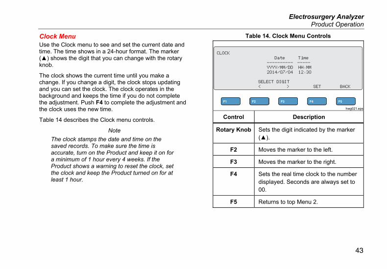
Clock Menu Use the Clock menu to see and set the current date and time. The time shows in a 24-hour format. The marker () shows the digit that you can change with the rotary knob.
The clock shows the current time until you make a change. If you change a digit, the clock stops updating and you can set the clock. The clock operates in the background and keeps the time if you do not complete the adjustment. Push F4 to complete the adjustment and the clock uses the new time.
Table 14 describes the Clock menu controls.
Note
The clock stamps the date and time on the saved records. To make sure the time is accurate, turn on the Product and keep it on for a minimum of 1 hour every 4 weeks. If the Product shows a warning to reset the clock, set the clock and keep the Product turned on for at least 1 hour.
Table 14. Clock Menu Controls
hwg021.eps
Control Description
Rotary Knob Sets the digit indicated by the marker ().
F2 Moves the marker to the left.
F3 Moves the marker to the right.
F4 Sets the real time clock to the number displayed. Seconds are always set to 00.
F5 Returns to top Menu 2.

QA-ES III Users Manual
44
Setup Communications The Product has a USB Device Port for communication to a computer (PC). Some Products also have wireless functionality. You can use the communications ports to:
• Send saved test records to a PC.
• Send commands and receive responses to control the Product remotely.
Use Ansur or a terminal emulation program (for example HyperTerminal or Tera Term) to set the COM port options. COM port settings are:
• 115,200 baud
• No parity
• 8 data bits
• 1 stop bit
• Hardware handshaking is on. (The Product uses hardware handshaking but does not use XON/XOFF software handshaking.)
Operating system requirements:
• Windows Vista
• Windows 7
• Windows 8 or later
USB Device Port The USB port on the Product (a Micro Type B connector) connects to a USB controller port on the PC (Type A rectangular connector). Use the supplied USB Type A-to-Micro-B cable to connect the Product to a PC.
The PC sees the USB Port while the cable is connected to the Product (even if the Product is turned off). If the cable is disconnected, the PC must close the port and reopen the connection.
Windows Software Driver The USB port uses an integrated circuit (IC) to convert USB to RS232. Adapter cables frequently use this IC (FT232R from the company FTDI). When the Product connects to a PC for the first time, the PC registers the Product as a virtual COM port (VCP). The virtual COM port looks like a serial (RS232) device.
The IC is compatible with the USB Version 2.0 Full Speed specification. The USB ID numbers are: VID 0403 and PID 6001.
Electrosurgery Analyzer Setup Communications
45
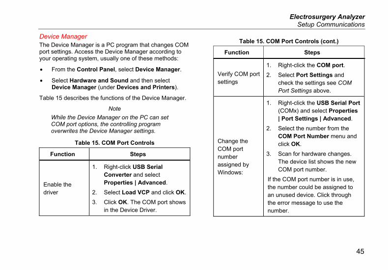
Device Manager The Device Manager is a PC program that changes COM port settings. Access the Device Manager according to your operating system, usually one of these methods:
• From the Control Panel, select Device Manager.
• Select Hardware and Sound and then select Device Manager (under Devices and Printers).
Table 15 describes the functions of the Device Manager.
Note
While the Device Manager on the PC can set COM port options, the controlling program overwrites the Device Manager settings.
Table 15. COM Port Controls
Function Steps
Enable the driver
1. Right-click USB Serial Converter and select Properties | Advanced.
2. Select Load VCP and click OK.
3. Click OK. The COM port shows in the Device Driver.
Table 15. COM Port Controls (cont.)
Function Steps
Verify COM port settings
1. Right-click the COM port.
2. Select Port Settings and check the settings see COM Port Settings above.
Change the COM port number assigned by Windows:
1. Right-click the USB Serial Port (COMx) and select Properties | Port Settings | Advanced.
2. Select the number from the COM Port Number menu and click OK.
3. Scan for hardware changes. The device list shows the new COM port number.
If the COM port number is in use, the number could be assigned to an unused device. Click through the error message to use the number.
QA-ES III Users Manual
46
Wireless Port For Products with wireless functionality, the wireless port communicates with a PC that has an 802.15 (Bluetooth) wireless interface. For PCs without the interface, use a commercially available USB adapter. The PC starts the interface when you connect the adapter. (Additional software is not necessary.)
The PC sees the wireless port while the Product is on. When the Product is turned off, the PC closes the port. When the wireless device is assigned to a COM port, the COM port reopens when the Product is turned on again.
Note
The wireless port on the Product is a Classic Bluetooth port not a Low Energy Bluetooth port.
To install a wireless device:
1. Right-click the Bluetooth Devices icon and select Add a Device, or select Show Bluetooth Devices | Add a Device.
The Product shows in the window. The serial number of the Product is part of the name.
Note
It is okay if the icon is a headset, or if the name is Bluetooth headset. These are defaults and the name will change to the Product.
2. Select the Product and click Next.
The system prompts you to compare the codes. Ignore the message and continue with the next step.
3. Make sure Yes is selected and click Next.
4. Select Driver Software Installation.
The system installs two standard serial-over-Bluetooth-link COM ports. The Bluetooth Peripheral Device will fail. Ignore the message and close the window. The Add a device window shows the device successfully added to the computer.
5. Close the Add a device window.
6. Right-click the Bluetooth icon and select Show Bluetooth Devices.
The Product name (including serial number) shows. Ignore the message about the missing driver for the Bluetooth Peripheral Device.
7. Right-click the Product and select Properties.
The Hardware section shows a COM port for a Standard Serial-over-Bluetooth link. Use this Outgoing COM port for the interface.
The Bluetooth Settings COM ports show that the Product has 2 COM ports: Outgoing (initiated by the PC) and Incoming (initiated by the Product). The system uses the Outgoing port only.
Electrosurgery Analyzer Setup Communications
47
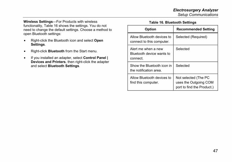
Wireless Settings—For Products with wireless functionality, Table 16 shows the settings. You do not need to change the default settings. Choose a method to open Bluetooth settings:
• Right-click the Bluetooth icon and select Open Settings.
• Right-click Bluetooth from the Start menu.
• If you installed an adapter, select Control Panel | Devices and Printers, then right-click the adapter and select Bluetooth Settings.
Table 16. Bluetooth Settings
Option Recommended Setting
Allow Bluetooth devices to connect to this computer.
Selected (Required)
Alert me when a new Bluetooth device wants to connect.
Selected
Show the Bluetooth icon in the notification area.
Selected
Allow Bluetooth devices to find this computer.
Not selected (The PC uses the Outgoing COM port to find the Product.)
QA-ES III Users Manual
48
Product Maintenance
XW Warning
To prevent possible electrical shock, fire, or personal injury, follow these guidelines:
• Do not use an extension cord or adapter plug.
• Do not operate the Product with covers removed or the case open. Hazardous voltage exposure is possible.
• Disconnect the mains power cord and input cables before you remove the Product covers.
• Remove the input signals before you clean the Product.
• Use only specified replacement parts.
• Have an approved technician repair the Product.
After troubleshooting or maintenance, restart the Product and ensure that it starts without errors.
Cleaning
WCaution
For safe operation and maintenance of the Product:
• Do not spray cleaning solution or water directly on the Product.
• Do not pour or drip liquid onto the Product.
The Product needs little maintenance or special care. To clean, wipe with a damp cloth.
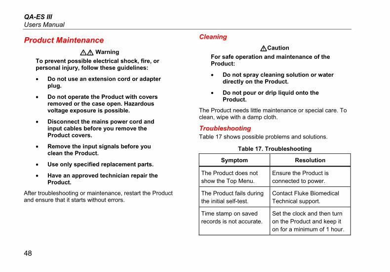
Troubleshooting Table 17 shows possible problems and solutions.
Table 17. Troubleshooting
Symptom Resolution
The Product does not show the Top Menu.
Ensure the Product is connected to power.
The Product fails during the initial self-test.
Contact Fluke Biomedical Technical support.
Time stamp on saved records is not accurate.
Set the clock and then turn on the Product and keep it on for a minimum of 1 hour.
Electrosurgery Analyzer Product Maintenance
49
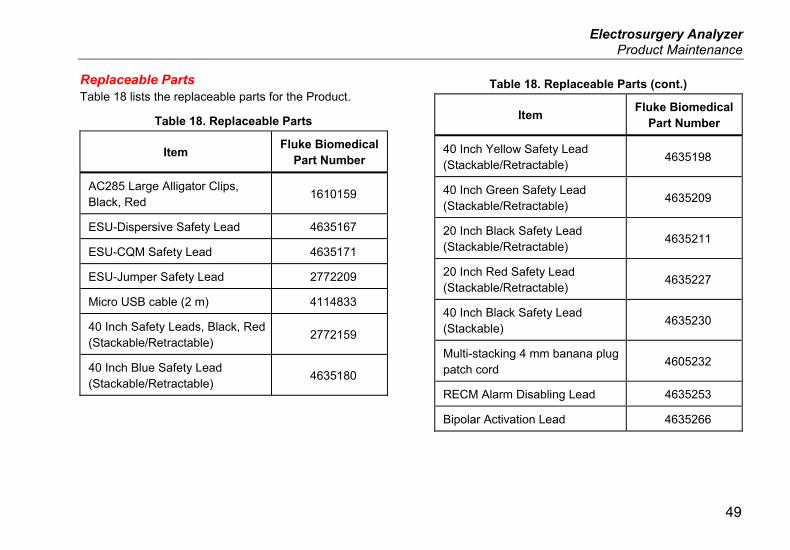
Replaceable Parts Table 18 lists the replaceable parts for the Product.
Table 18. Replaceable Parts
Item Fluke Biomedical
Part Number
AC285 Large Alligator Clips, Black, Red
1610159
ESU-Dispersive Safety Lead 4635167
ESU-CQM Safety Lead 4635171
ESU-Jumper Safety Lead 2772209
Micro USB cable (2 m) 4114833
40 Inch Safety Leads, Black, Red (Stackable/Retractable) 2772159
40 Inch Blue Safety Lead (Stackable/Retractable) 4635180
Table 18. Replaceable Parts (cont.)
Item Fluke Biomedical
Part Number
40 Inch Yellow Safety Lead (Stackable/Retractable) 4635198
40 Inch Green Safety Lead (Stackable/Retractable) 4635209
20 Inch Black Safety Lead (Stackable/Retractable) 4635211
20 Inch Red Safety Lead (Stackable/Retractable) 4635227
40 Inch Black Safety Lead (Stackable) 4635230
Multi-stacking 4 mm banana plug patch cord
4605232
RECM Alarm Disabling Lead 4635253
Bipolar Activation Lead 4635266
QA-ES III Users Manual
50
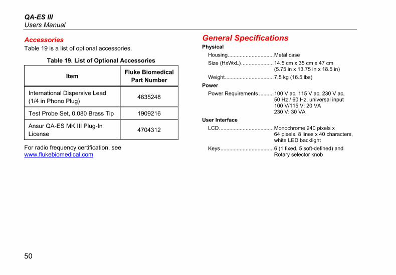
Accessories Table 19 is a list of optional accessories.
Table 19. List of Optional Accessories
Item Fluke Biomedical
Part Number
International Dispersive Lead (1/4 in Phono Plug) 4635248
Test Probe Set, 0.080 Brass Tip 1909216
Ansur QA-ES MK III Plug-In License
4704312
For radio frequency certification, see www.flukebiomedical.com
General Specifications Physical
Housing ............................... Metal case
Size (HxWxL) ...................... 14.5 cm x 35 cm x 47 cm (5.75 in x 13.75 in x 18.5 in)
Weight ................................. 7.5 kg (16.5 lbs)
Power
Power Requirements .......... 100 V ac, 115 V ac, 230 V ac, 50 Hz / 60 Hz, universal input 100 V/115 V: 20 VA 230 V: 30 VA
User Interface
LCD ..................................... Monochrome 240 pixels x 64 pixels, 8 lines x 40 characters, white LED backlight
Keys .................................... 6 (1 fixed, 5 soft-defined) and Rotary selector knob
Electrosurgery Analyzer Technical Specifications
51
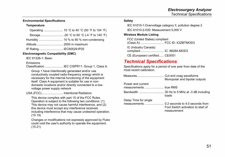
Environmental Specifications
Temperature
Operating ....................... 10 °C to 40 °C (50 °F to 104 °F)
Storage ........................... -20 °C to 60 °C (-4 °F to 140 °F)
Humidity ............................. 10 % to 90 % non-condensing
Altitude ............................... 2000 m maximum
IP Rating............................. IEC60529:IP20
Electromagnetic Compatibility (EMC)
IEC 61326-1: Basic
Emissions Classification ...................... IEC CISPR11: Group 1, Class A.
Group 1 have intentionally generated and/or use conductively coupled radio-frequency energy which is necessary for the internal functioning of the equipment itself. Class A equipment is suitable for use in non-domestic locations and/or directly connected to a low-voltage power supply network
USA (FCC) ......................... Intentional Radiators
This device complies with part 15 of the FCC Rules. Operation is subject to the following two conditions: (1) This device may not cause harmful interference, and (2) this device must accept any interference received, including interference that may cause undesired operation. (15.19)
Changes or modifications not expressly approved by Fluke could void the user's authority to operate the equipment. (15.21)
Safety
IEC 61010-1:Overvoltage category II, pollution degree 2
IEC 61010-2-030: Measurement 5,000 V
Wireless Module Listing
FCC (United States) compliant (Class A) ............................ FCC ID: X3ZBTMOD3
IC (Industry Canada) compliant ............................ IC: 8828A-MOD3
CE (European) certified...... CE0051
Technical Specifications Specifications apply for a period of one year from date of the most recent calibration.
Measures ................................ Cut and coag waveforms Monopolar and bipolar outputs
Power and current measurements ....................... true RMS
Bandwidth ............................. 30 Hz to 5 MHz at -3 dB including loads
Delay Time for single measurements ....................... 0.2 seconds to 4.0 seconds from
Foot Switch activation to start of measurement
QA-ES III Users Manual
52
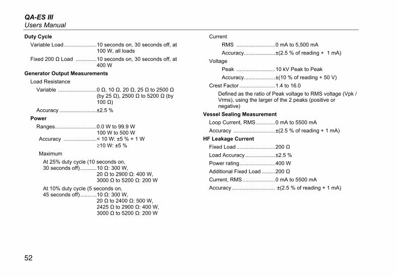
Duty Cycle
Variable Load ...................... 10 seconds on, 30 seconds off, at 100 W, all loads
Fixed 200 Ω Load .............. 10 seconds on, 30 seconds off, at 400 W
Generator Output Measurements
Load Resistance
Variable .......................... 0 Ω, 10 Ω, 20 Ω, 25 Ω to 2500 Ω (by 25 Ω), 2500 Ω to 5200 Ω (by 100 Ω)
Accuracy ......................... ±2.5 %
Power
Ranges ............................ 0.0 W to 99.9 W 100 W to 500 W
Accuracy ...................... < 10 W: ±5 % + 1 W ≥10 W: ±5 %
Maximum
At 25% duty cycle (10 seconds on, 30 seconds off) ........... 10 Ω: 300 W,
20 Ω to 2900 Ω: 400 W, 3000 Ω to 5200 Ω: 200 W
At 10% duty cycle (5 seconds on, 45 seconds off) ........... 10 Ω: 300 W,
20 Ω to 2400 Ω: 500 W, 2425 Ω to 2900 Ω: 400 W, 3000 Ω to 5200 Ω: 200 W
Current
RMS .......................... 0 mA to 5,500 mA
Accuracy ..................... ±(2.5 % of reading + 1 mA)
Voltage
Peak .......................... 10 kV Peak to Peak
Accuracy ..................... ±(10 % of reading + 50 V)
Crest Factor ........................ 1.4 to 16.0
Defined as the ratio of Peak voltage to RMS voltage (Vpk / Vrms), using the larger of the 2 peaks (positive or negative)
Vessel Sealing Measurement
Loop Current, RMS ............. 0 mA to 5500 mA
Accuracy ............................ ±(2.5 % of reading + 1 mA)
HF Leakage Current
Fixed Load .......................... 200 Ω
Load Accuracy .................... ±2.5 %
Power rating ........................ 400 W
Additional Fixed Load ......... 200 Ω
Current, RMS ...................... 0 mA to 5500 mA
Accuracy ............................. ±(2.5 % of reading + 1 mA)
Electrosurgery Analyzer Technical Specifications
53
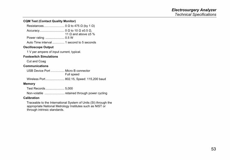
CQM Test (Contact Quality Monitor)
Resistances ........................ 0 Ω to 475 Ω (by 1 Ω)
Accuracy............................. 0 Ω to 10 Ω ±0.5 Ω, 11 Ω and above ±5 %
Power rating ...................... 0.5 W
Auto Time interval .............. 1 second to 5 seconds
Oscilloscope Output
1 V per ampere of input current, typical.
Footswitch Simulations
Cut and Coag
Communications
USB Device Port ................ Micro B connector Full speed
Wireless Port ...................... 802.15, Speed: 115,200 baud
Memory
Test Records ...................... 5,000
Non-volatile ....................... retained through power cycling
Calibration
Traceable to the International System of Units (SI) through the appropriate National Metrology Institutes such as NIST or through intrinsic standards.

QA-ES III Users Manual
54