pws helical antenna - professional wireless · pws helical antennas at work: unparalleled drop-out...
TRANSCRIPT
PWS HELICAL ANTENNAS AT WORK:
Unparalleled drop-out free RF
performance for In-Ear
Monitors and Wireless Mics,
delivering more than double
the range over other antennas
The PWS Helical Antenna is part of a new generation of antennas that provide greater bandwidth, longer range gain and more flexibility in wireless communications. Unlike the traditional whip antenna, which transmit and receive signals in a single polarization, the helical antenna distributes signals multi-dimensionally. The circular motion of the RF field emitted by the helical antenna reduces the risk of drop-outs and guarantees the strongest possible signal.
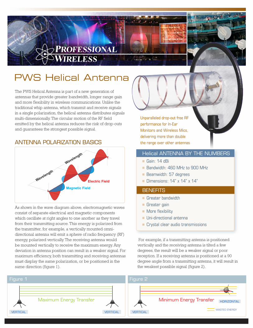
AntennA POLARIZAtIOn BASICS
As shown in the wave diagram above, electromagnetic waves consist of separate electrical and magnetic components which oscillate at right angles to one another as they travel from their transmitting source. This energy is polarized from the transmitter, for example, a vertically mounted omni-directional antenna will emit a sphere of radio frequency (RF) energy, polarized vertically. The receiving antenna would be mounted vertically to receive the maximum energy. Any deviation in antenna position can result in a weaker signal. For maximum efficiency, both transmitting and receiving antennas must display the same polarization, or be positioned in the same direction (figure 1).
PWS Helical Antenna
Helical AntennA BY tHe nUMBeRS Gain: 14 dBi Bandwidth: 460 MHz to 900 MHz Beamwidth: 57 degrees Dimensions: 14” x 14” x 14”
BeneFItS Greater bandwidth Greater gain More flexibility Uni-directional antenna Crystal clear audio transmissions
VeRtICAL
HORIZOntALMaximum energy transfer Minimum energy transfer
Figure 1 Figure 2
WASted eneRgYVeRtICAL VeRtICAL
For example, if a transmitting antenna is positioned vertically and the receiving antenna is tilted a few degrees, the result will be a weaker signal or poor reception. If a receiving antenna is positioned at a 90 degree angle from a transmitting antenna, it will result in the weakest possible signal (figure 2).
Electric FieldWavelength
Wavelength
Magnetic Field
WORd On tHe StReet
“The antenna works great wherever I am in the venue. I can still get RF even in the dressing rooms through these thick walls; it’s incredible!” – George Squires, monitor engineer for REM and Red Hot Chili Peppers
“This was designed by the same guy who does the RF support for the Super Bowl and they are used at the Super Bowl every year. Rat uses them because they are amazing for in-ears and wireless mics.” – Jon Rat Sound
FOR MORe InFORMAtIOn
www.professionalwireless.com/helical
POLARIZAtIOn SOLUtIOnSTypical antennas suffer from polarization. This isn’t so much of a problem under normal circumstances, for example, the large vertical FM antenna tower broadcasting a local radio station is being received by the vertically mounted antenna on your car. The trouble is, in the entertainment and events industry, antenna polarization is becoming a major issue. Larger venues and more RF used for performer microphones, in-ear-monitors (IEMs) and crew communication are causing headaches for audio engineers.
The helical antenna, which eliminates polarization problems, has been around for decades, but was previously used only for military applications and for satellite communications. Helical Antennas are increasingly being utilized in the entertainment and events industry where drop-out free coverage is critical.
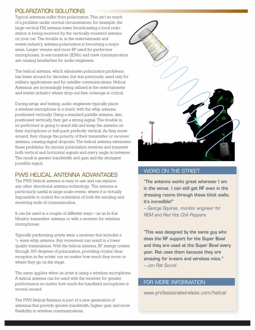
During setup and testing, audio engineers typically place a wireless microphone in a stand, with the whip antenna positioned vertically. Using a standard paddle antenna, also positioned vertically, they get a strong signal. The trouble is, no performer is going to stand still and keep the antenna on their microphone or belt pack perfectly vertical. As they move around, they change the polarity of their transmitter or receiver antenna, causing signal dropouts. The helical antenna eliminates these problems. Its circular polarization receives and transmits both vertical and horizontal signals and every angle in between. The result is greater bandwidth and gain and the strongest possible signal.
PWS HeLICAL AntennA AdVAntAgeSThe PWS Helical antenna is easy to use and can replace any other directional antenna technology. The antenna is particularly useful in large-scale events, where it is virtually impossible to control the orientation of both the sending and receiving ends of communication.
It can be used in a couple of different ways – as an In-Ear Monitor transmitter antenna or with a receiver for wireless microphones.
Typically performing artists wear a receiver that includes a ¼ wave whip antenna. Any movement can result in a lower quality transmission. With the helical antenna, RF energy rotates through 360 degrees of polarization, providing crystal clear reception in the artists’ ear no matter how much they move or where they go on the stage.
The same applies when an artist is using a wireless microphone. A helical antenna can be used with the receiver for greater performance no matter how much the handheld microphone is moved around. The PWS Helical Antenna is part of a new generation of antennas that provide greater bandwidth, higher gain and more flexibility in wireless communications.
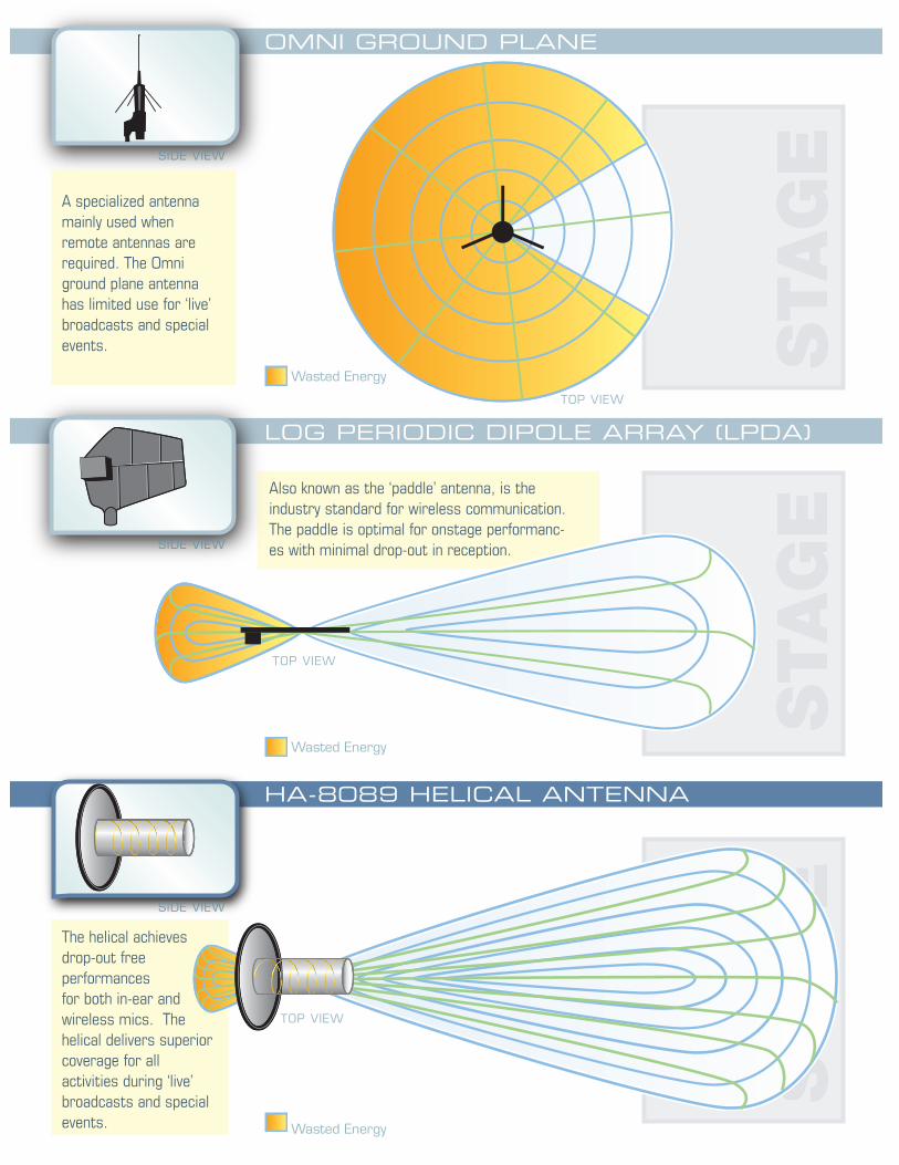
OmNI GROuND PLANE
Wasted energy
LOG PERIODIC DIPOLE ARRAy (LPDA)
HA-8089 HELICAL ANTENNA
A specialized antenna mainly used when remote antennas are required. The Omni ground plane antenna has limited use for ‘live’ broadcasts and special events.
Also known as the ‘paddle’ antenna, is the industry standard for wireless communication. The paddle is optimal for onstage performanc-es with minimal drop-out in reception.
The helical achieves drop-out free performances for both in-ear and wireless mics. The helical delivers superior coverage for all activities during ‘live’ broadcasts and special events.
Wasted energy
Wasted energy
SIde VIeW
tOP VIeW
SIde VIeW
SIde VIeW
tOP VIeW
tOP VIeW

HA-8089 HELICAL
ENGINEERING DATA
SPECIFICATIONS
RF Frequency Range / Bandwidth460 - 900 MHz
Impedance50 ohms
Beamwidth57 degrees
Antenna Gain14 dBi (on axis)
Front-to-Back Ratio / Rear Rejection30 dB
DC/AC Power SourceNot required
RF ConnectorBNC female, right angle
Dual Mounting Adapter5/8”-27 U.S. standard3/8”-16 European standard
Antenna Cable RetainerPlastic clamp on rear of antenna
Estimated Operating Temperature-30 degrees F to 180 degrees F [-34 degrees C to 80 degrees C]
Construction MaterialClear Polycarbonate plastic Net Weight: 3 lbs 11 oz [1.7 kg]
Shipping Weight: 5 lbs [ 2.3 kg]
PWS HELICAL ANTENNAS AT WORK:
THE APPRENTICE FINALE
SUPERCROSS
QVC
For More Information Contact Our Sales Department at:
407-240-28809468 American Eagle Way Suite 100Orlando, FL 32837-8380
Distributed by:
© 2006 Professional Wireless Systems, A Masque Sound Company. All Rights Reserved
A Masque Sound Company
www.masquesound.com www.shure.comwww.professionalwireless.com
Sheet # MAS 05-0039
THE SUPERBOWL
Please ask about our
Low Loss Cable
Please ask about our
Low Loss Cable