purco inc. - your partner in technologypurco.qc.ca/ftp/wattsups'...
TRANSCRIPT

YourPartner inTechnology
MMG-NEOSID
Magnetic Components
Catalogue

MMG Companies: MMG-NeosidHuntingdon MagnetsMMG SailcrestMMG-North AmericaNeosid Canada LtdNeosid Australia Pty LtdNeosid (India) PVT Ltd
MMG-Neosid has been manufacturing magnetic materials since its foundation in 1936
and now manufactures an extensive range of soft ferrite components and accessories.
These are used in the Industrial, Computer, Telecommunications and Automotive/
Aerospace industries and include both Mn-Zn and Ni-Zn ferrite components, thermo-
set/thermoplastic formers and bobbins, and clips.
We also offer a range of toroids and rods (leaded and un-leaded) in Iron and Nickel-
Iron Powders including Molypermalloy.
Isotropic hard ferrite magnets and resin bonded Neodymium-Iron-Boron magnets are
also available from Huntingdon Magnets - a division of MMG-Neosid, based in
Letchworth.
Always sensitive to market changes, MMG-Neosid is constantly developing new ferrite
materials and component geometries to meet changing customer requirements and it
is the experience gained from this that allows us to provide the very best of technical
support and assistance to our customers at all stages of their projects.
Our ISO 9002 accreditation forms the basis of our Quality Assurance Policy but we
would like to think we go beyond the scope of this and offer quality in every aspect of
the way we do business.
The Company’s policy is one of continuousimprovement and development and the right tochange materials, designs, dimensions anddescriptive matter, etc. at any time without notice isreserved.Specifications and information contained within thisbrochure are intended for guidance only.
MMG-Neosid has exercised the utmost care andattention in compiling the information contained inthis brochure and believes it to be accurate andreliable. However, it is provided for illustrative purposes onlyand MMG-Neosid gives no warranty and makes norepresentation that the theory or other informationcontained in the brochure is suitable for anyparticular purpose or application.MMG-Neosid shall not be liable for any loss, director consequential, which may result from the use ofsuch information.
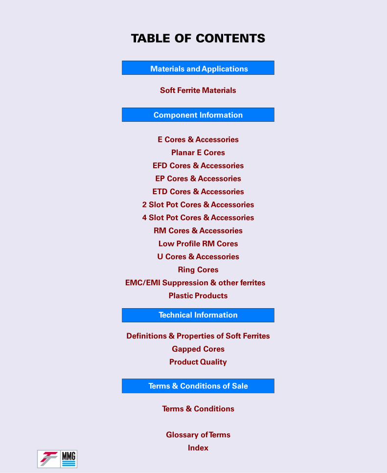
Materials and Applications
TABLE OF CONTENTS
Component Information
E Cores & Accessories
Planar E Cores
EFD Cores & Accessories
EP Cores & Accessories
ETD Cores & Accessories
2 Slot Pot Cores & Accessories
4 Slot Pot Cores & Accessories
RM Cores & Accessories
Low Profile RM Cores
U Cores & Accessories
Ring Cores
EMC/EMI Suppression & other ferrites
Plastic Products
Soft Ferrite Materials
Technical Information
Terms & Conditions of Sale
Terms & Conditions
Glossary of Terms
Index
Definitions & Properties of Soft Ferrites
Gapped Cores
Product Quality
F47
F45
F44
F5A
F9
F9C
Soft Ferrite MaterialsSpecific Material Data
F10
F39
P11
P12
F58
F19
F25
F28
F29
F14
F16

Material CharacteristicsThe following data tabulates the specified materialcharacteristics of MMG ferrites.Supplementary graphs show typical performance.These are given for guidance only.
Data is derived from measurements on toroidalcores and the values obtained cannot be directlytransferred to products of another shape and size.
The Nickel-Zinc ferrites (mainly used in open-circuitconfigurations) are described by Loss Factorscorresponding to the sum of the residual and eddycurrent losses.The grades of Manganese-Zinc ferrites mainlydeveloped for power applications are characterisedby the Power Loss Density under specifiedconditions.Other Manganese-Zinc ferrites, especially thoseused in low frequency telecommunication
Information given for individual grades of ferritespecify the typical or maximum Loss Factors for arange of frequencies where these losses remainfairly low. Generally speaking, these loss factorsincrease with frequency at a steady rate, slowly atfirst and then rapidly increasing to overtake thefrequency rise. The point at which this acceleratedrate of increase of loss factors occurs depends uponthe composition and sintering conditions and mayvary between batches of cores.
At frequencies well outside their normal range ofapplication, all ferrites exhibit high losscharacteristics, and are extensively used forsuppression purposes.
Applications GuideMMG ferrites are used in an extensive range ofproducts and applications. Electronics applicationsare constantly developing. Listed below is anapplications guide outlining the most popular use ofMMG material grades. It is intended for guidanceonly.
Pot cores/RM cores for inductors, transformers -
Grades: P11, P12, F58, F5A, F44, F45, F47, F9,F9C, F10, F39
Low power and pulse transformer cores -
Grades: F9, F9C, F10, F39, F14
Balun cores -
Grades: P11, F9, F9C, F10, F19, F14
High power transformer core (E,U & Ring) -
Grades: F5A, F44, F45, F47
Suppression cores -
Grades: F9, F9C, F10, F39, F19, F14
Toroidal cores -
Grades: All grades.
Aerial Rods and slabs -
Long and medium waves:
Grades: F14Short wave and VHF:
Grades: F16, F25, F28, F29
Screw cores, rods, pins and tubes -
Grades: F14, F25, F29
High frequency welding impeders -
Grades: F14, F59
applications, are characterised by both the residualand eddy current loss factor and the hysteresis lossfactors.
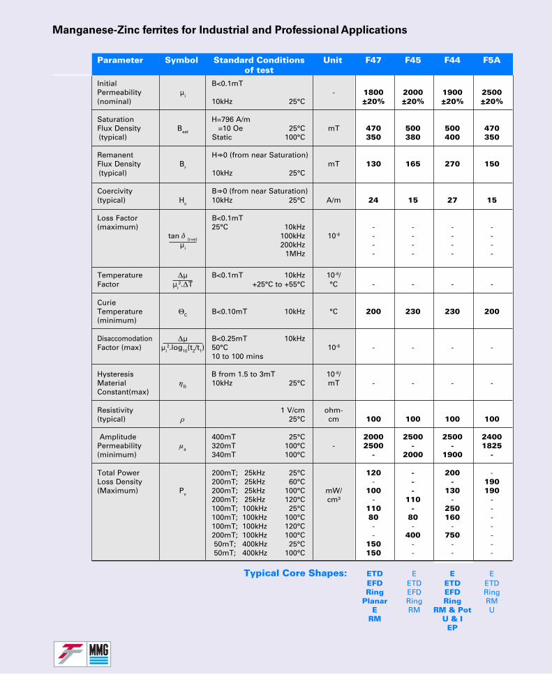
Manganese-Zinc ferrites for Industrial and Professional Applications
Parameter Symbol Standard Conditions Unit F47 F45 F44 F5Aof test
Initial B<0.1mTPermeability µi - 1800 2000 1900 2500(nominal) 10kHz 25°C ±20% ±20% ±20% ±20%
Saturation H=796 A/mFlux Density Bsat =10 Oe 25°C mT 470 500 500 470
(typical) Static 100°C 350 380 400 350
Remanent H⇒0 (from near Saturation)Flux Density Br mT 130 165 270 150
(typical) 10kHz 25°C
Coercivity B⇒0 (from near Saturation)(typical) Hc 10kHz 25°C A/m 24 15 27 15
Loss Factor B<0.1mT(maximum) 25°C 10kHz - - - -
tan δ (r+e) 100kHz 10-6 - - - -µi 200kHz - - - -
1MHz - - - -
Temperature ∆µ B<0.1mT 10kHz 10-6/Factor µi
2.∆T +25°C to +55°C °C - - - -
CurieTemperature ΘC B<0.10mT 10kHz °C 200 230 230 200(minimum)
Disaccomodation ∆µ B<0.25mT 10kHzFactor (max) µi
2.log10(t2/t1) 50°C 10-6 - - - -10 to 100 mins
Hysteresis B from 1.5 to 3mT 10-6/Material ηΒ 10kHz 25°C mT - - - -Constant(max)
Resistivity 1 V/cm ohm-(typical) ρ 25°C cm 100 100 100 100
Amplitude 400mT 25°C 2000 2500 2500 2400Permeability µa 320mT 100°C - 2500 - - 1825(minimum) 340mT 100°C - 2000 1900 -
Total Power 200mT; 25kHz 25°C 120 - 200 -Loss Density 200mT; 25kHz 60°C - - - 190(Maximum) Pv 200mT; 25kHz 100°C mW/ 100 - 130 190
200mT; 25kHz 120°C cm³ - 110 - -100mT; 100kHz 25°C 110 - 250 -100mT; 100kHz 100°C 80 80 160 -100mT; 100kHz 120°C - - - -200mT; 100kHz 100°C - 400 750 - 50mT; 400kHz 25°C 150 - - - 50mT; 400kHz 100°C 150 - - -
Typical Core Shapes: ETD E E EEFD ETD ETD ETDRing EFD EFD Ring
Planar Ring Ring RME RM RM & Pot U
RM U & IEP
InitialPermeability(Nominal)
SaturationFlux Density(Typical)
RemanentFlux Density(Typical)
Coercivity(Typical)
Loss Factor(Maximum)
TemperatureFactor
CurieTemperature(Minimum)
DisaccomodationFactor (Max)
HysteresisMaterialConstant (Max)
Resistivity(Typical)
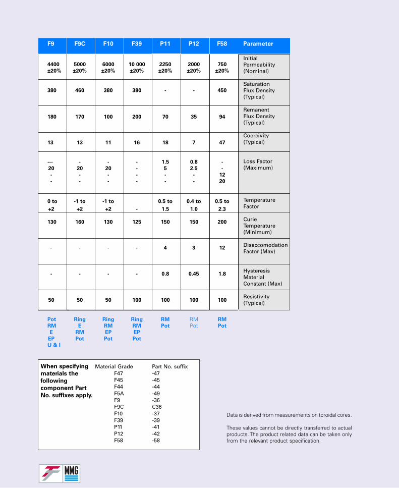
Data is derived from measurements on toroidal cores.
These values cannot be directly transferred to actualproducts. The product related data can be taken onlyfrom the relevant product specification.
Material Grade Part No. suffixF47 -47F45 -45F44 -44F5A -49F9 -36F9C C36F10 -37F39 -39P11 -41P12 -42F58 -58
When specifying
materials the
following
component Part
No. suffixes apply.
F9 F9C F10 F39 P11 P12 F58 Parameter
4400 5000 6000 10 000 2250 2000 750
±20% ±20% ±20% ±20% ±20% ±20% ±20%
380 460 380 380 - - 450
180 170 100 200 70 35 94
13 13 11 16 18 7 47
--- - - - 1.5 0.8 -
20 20 20 - 5 2.5 -
- - - - - - 12
- - - - - - 20
0 to -1 to -1 to 0.5 to 0.4 to 0.5 to
+2 +2 +2 - 1.5 1.0 2.3
130 160 130 125 150 150 200
- - - - 4 3 12
- - - - 0.8 0.45 1.8
50 50 50 100 100 100 100
Pot Ring Ring Ring RM RM RM
RM E RM RM Pot Pot Pot
E RM EP EP
EP Pot Pot Pot
U & I
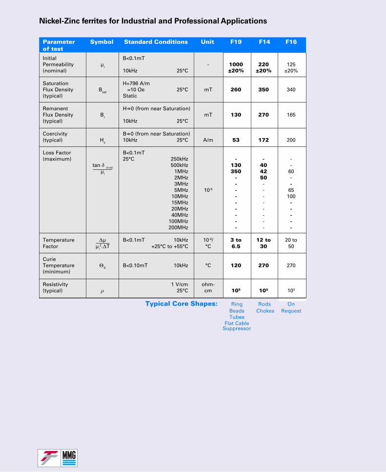
Nickel-Zinc ferrites for Industrial and Professional Applications
Parameter Symbol Standard Conditions Unit F19 F14 F16of test
Initial B<0.1mTPermeability µi - 1000 220 125(nominal) 10kHz 25°C ±20% ±20% ±20%
Saturation H=796 A/mFlux Density Bsat =10 Oe 25°C mT 260 350 340(typical) Static
Remanent H⇒0 (from near Saturation)Flux Density Br mT 130 270 165(typical) 10kHz 25°C
Coercivity B⇒0 (from near Saturation)(typical) Hc 10kHz 25°C A/m 53 172 200
Loss Factor B<0.1mT(maximum) 25°C 250kHz - - -
tan δ (r+e) 500kHz 130 40 -µi 1MHz 350 42 60
2MHz - 50 -3MHz - - -5MHz 10-6 - - 65
10MHz - - 10015MHz - - -20MHz - - -40MHz - - -
100MHz - - -200MHz - - -
Temperature ∆µ B<0.1mT 10kHz 10-6/ 3 to 12 to 20 toFactor µi
2.∆T +25°C to +55°C °C 6.5 30 50
CurieTemperature ΘΧ B<0.10mT 10kHz °C 120 270 270(minimum)
Resistivity 1 V/cm ohm-(typical) ρ 25°C cm 105 105 105
Typical Core Shapes: Ring Rods OnBeads Chokes RequestTubes
Flat CableSuppressor
InitialPermeability(Nominal)
SaturationFlux Density(Typical)
RemanentFlux Density(Typical)
Coercivity(Typical)
Loss Factor(Maximum)
TemperatureFactor
CurieTemperature(Minimum)
Resistivity(Typical)
Data is derived from measurements on toroidal cores.
These values cannot be directly transferred to actualproducts. The product related data can be taken onlyfrom the relevant product specification.
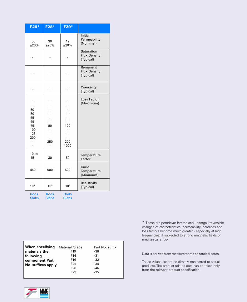
* These are perminvar ferrites and undergo irreversiblechanges of characteristics (permeability increases andloss factors become much greater - especially at highfrequencies) if subjected to strong magnetic fields ormechanical shock.
F25* F28* F29*
50 30 12±20% ±20% ±20%
- - -
- - -
- - -
- - -- - -
50 - -50 - -55 - -65 - -75 80 100100 - -125 - -300 - -- 250 200- - 1000
10 to15 30 50
450 500 500
105 105 105
Rods Rods RodsSlabs Slabs Slabs
Material Grade Part No. suffixF19 -38F14 -31F16 -32F25 -34F28 -46F29 -35
When specifying
materials the
following
component Part
No. suffixes apply.
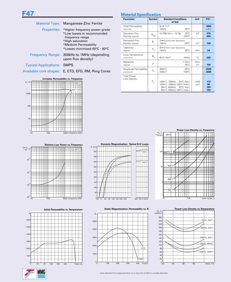
Parameter Symbol Standard Conditions Unit F47of test
Initial Permeability B<0.1mT - 1800
(nominal) 10kHz 25°C ±20%
Saturation Flux H=796 A/m = 10 Oe 25°C mT 470
Density (typical) 100°C 350
Remanent Flux H 0 (from near Saturation)Density (typical) 10kHz 25°C mT 130
Coercivity B 0 (from near Saturation)(typical) 10kHz 25°C A/m 24
Curie Temperature(minimum) B<0.10mT 10kHz °C 200
Resistivity 1 V/cm ohm-(typical) 25°C cm 100
Amplitude Permeability 400mT 25°C - 2500
(minimum) 340mT 100°C 2000
Total PowerLoss Density
100mT; 100kHz 25°C (typ.) mW/ 110
100mT; 100kHz 100°C (max.) cm³ 80
150mT; 400kHz 25°C (typ.) 150
150mT; 400kHz 100°C (max.) 150
Bsat
Br
-
Hc
Θc
ρ
µa
Pv
Material Specification
Relative Loss Factor vs. Frequency
Initial Permeability vs. Temperature
Complex Permeability vs. Frequency
Power Loss Density vs. Frequency
Power Loss Density vs. TemperatureStatic Magnetisation: Permeability vs. B
Dynamic Magnetisation: Typical B-H Loops
23°C
100°C
Data derived from measurements on a ring core of 30mm outside diameter.
F47Material Type: Manganese-Zinc Ferrite
Properties: *Higher frequency power grade*Low losses in recommended
frequency range*High saturation*Medium Permeability*Losses minimised 60°C - 80°C
Frequency Range: 300kHz to 1MHz (dependingupon flux density)
Typical Applications: SMPS.
Available core shapes: E, ETD, EFD, RM, Ring Cores.
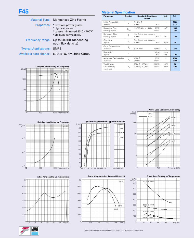
Parameter Symbol Standard Conditions Unit F45of test
Initial Permeability B<0.1mT - 2000
(nominal) 10kHz 25°C ±20%
Saturation Flux H=796 A/m = 10 Oe 25°C mT 500
Density (typical) 100°C 380
Remanent Flux H 0 (from near Saturation)Density (typical) 10kHz 25°C mT 165
Coercivity B 0 (from near Saturation)(typical) 10kHz 25°C A/m 15
Curie Temperature(minimum) B<0.10mT 10kHz °C 230
Resistivity 1 V/cm ohm-(typical) 25°C cm 100
Amplitude Permeability 400mT 25°C - 2500
(minimum) 340mT 100°C 2000
Total Power 100mT; 100kHz 100°C mW/ 80
Loss Density Pv 200mT; 100kHz 100°C cm³ 400
(maximum)
Bsat
Br
-
Hc
Θc
ρ
µa
Material Specification
Relative Loss Factor vs. Frequency
Initial Permeability vs. Temperature
Complex Permeability vs. Frequency
Power Loss Density vs. Frequency
Power Loss Density vs. TemperatureStatic Magnetisation: Permeability vs. B
Dynamic Magnetisation: Typical B-H Loops
Data is derived from measurements on a ring core of 30mm outside diameter.
F45Material Type: Manganese-Zinc Ferrite
Properties: *Low loss power grade.*High saturation*Losses minimised 80°C - 100°C*Medium permeability
Frequency range: Up to 500kHz (dependingupon flux density)
Typical Applications: SMPS.
Available core shapes: E, U, ETD, RM, Ring Cores.
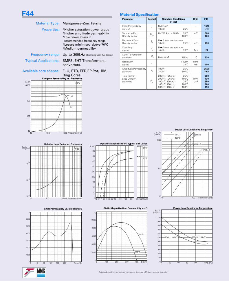
Parameter Symbol Standard Conditions Unit F44of test
Initial Permeability B<0.1mT - 1900
(nominal) 10kHz 25°C ±20%
Saturation Flux H=796 A/m = 10 Oe 25°C mT 500
Density (typical) 100°C 400
Remanent Flux H 0 (from near Saturation)Density (typical) 10kHz 25°C mT 270
Coercivity B 0 (from near Saturation)(typical) 10kHz 25°C A/m 27
Curie Temperature(minimum) B<0.10mT 10kHz °C 230
Resistivity 1 V/cm ohm-(typical) 25°C cm 100
Amplitude Permeability 400mT 25°C - 2500
(minimum) 340mT 100°C 1900
Total Power 200mT; 25kHz 25°C 200
Loss Density 200mT; 25kHz 100°C mW/ 130
(maximum) 100mT; 100kHz 25°C cm³ 250
100mT; 100kHz 100°C 160
200mT; 100kHz 100°C 750
Bsat
Br
-
Hc
Θc
ρ
µa
Pv
Material Specification
Relative Loss Factor vs. Frequency
Initial Permeability vs. Temperature
Complex Permeability vs. Frequency
Power Loss Density vs. Frequency
Power Loss Density vs. TemperatureStatic Magnetisation: Permeability vs. B
Dynamic Magnetisation: Typical B-H Loops
Data is derived from measurements on a ring core of 30mm outside diameter.
Complex Permeability vs. Frequency
F44Material Type: Manganese-Zinc Ferrite
Properties: *Higher saturation power grade*Higher amplitude permeability*Low power losses in recommended frequency range*Losses minimised above 70°C*Medium permeability
Frequency range: Up to 300kHz (depending upon flux density)
Typical Applications: SMPS, EHT Transformers,converters.
Available core shapes: E, U, ETD, EFD,EP,Pot, RM,Ring Cores.
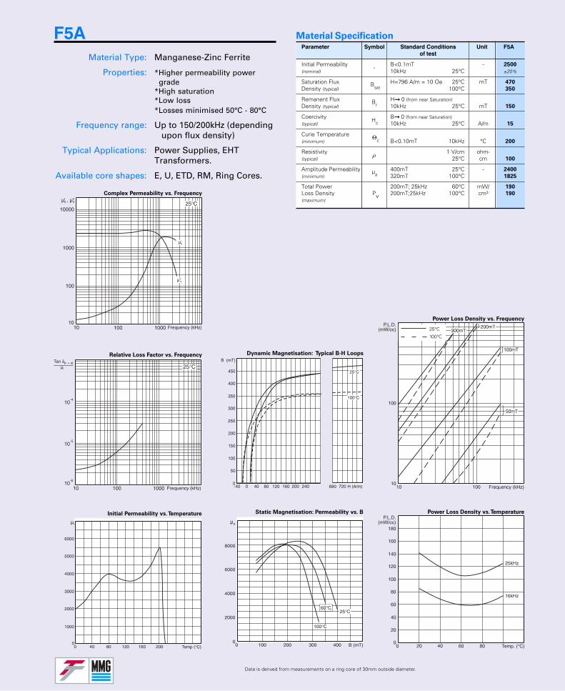
Parameter Symbol Standard Conditions Unit F5Aof test
Initial Permeability B<0.1mT - 2500
(nominal) 10kHz 25°C ±20%
Saturation Flux H=796 A/m = 10 Oe 25°C mT 470
Density (typical) 100°C 350
Remanent Flux H 0 (from near Saturation)Density (typical) 10kHz 25°C mT 150
Coercivity B 0 (from near Saturation)(typical) 10kHz 25°C A/m 15
Curie Temperature(minimum) B<0.10mT 10kHz °C 200
Resistivity 1 V/cm ohm-(typical) 25°C cm 100
Amplitude Permeability 400mT 25°C - 2400
(minimum) 320mT 100°C 1825
Total Power 200mT; 25kHz 60°C mW/ 190
Loss Density Pv 200mT;25kHz 100°C cm³ 190
(maximum)
Bsat
Br
-
Hc
Θc
ρ
µa
Material Specification
Relative Loss Factor vs. Frequency
Initial Permeability vs. Temperature
Complex Permeability vs. Frequency
Power Loss Density vs. Frequency
Power Loss Density vs. TemperatureStatic Magnetisation: Permeability vs. B
Dynamic Magnetisation: Typical B-H Loops
Data is derived from measurements on a ring core of 30mm outside diameter.
25°C
100°C
F5AMaterial Type: Manganese-Zinc Ferrite
Properties: *Higher permeability power grade*High saturation*Low loss*Losses minimised 50°C - 80°C
Frequency range: Up to 150/200kHz (dependingupon flux density)
Typical Applications: Power Supplies, EHTTransformers.
Available core shapes: E, U, ETD, RM, Ring Cores.
60°C
Relative Loss Factor vs. Frequency
Complex Permeability vs. Frequency
Dynamic Magnetisation: Typical B-H Loops
Data is derived from measurements on a ring core of 30mm outside diameter.
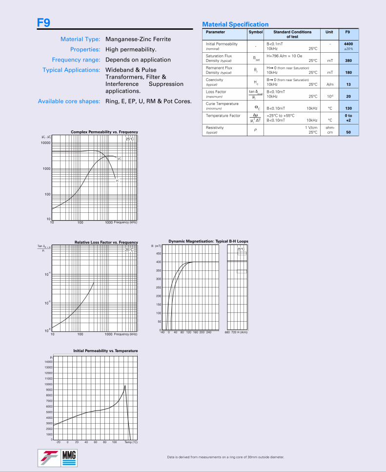
Parameter Symbol Standard Conditions Unit F9of test
Initial Permeability B<0.1mT - 4400
(nominal) 10kHz 25°C ±20%
Saturation Flux H=796 A/m = 10 OeDensity (typical) 25°C mT 380
Remanent Flux H 0 (from near Saturation)Density (typical) 10kHz 25°C mT 180
Coercivity B 0 (from near Saturation)(typical) 10kHz 25°C A/m 13
Loss Factor B<0.10mT(maximum) 10kHz 25°C 10-6 20
Curie Temperature(minimum) B<0.10mT 10kHz °C 130
Temperature Factor +25°C to +55°C 0 to
B<0.10mT 10kHz °C +2
Resistivity 1 V/cm ohm-(typical) 25°C cm 50
Bsat
Br
-
Hc
ΘC
Material Specification
ρ
F9Material Type: Manganese-Zinc Ferrite
Properties: High permeability.
Frequency range: Depends on application
Typical Applications: Wideband & PulseTransformers, Filter &Interference Suppressionapplications.
Available core shapes: Ring, E, EP, U, RM & Pot Cores.
Initial Permeability vs. Temperature
∆µµi
2.∆T
tan δ(r+e)
µi
Relative Loss Factor vs. Frequency
Initial Permeability vs. Temperature
Complex Permeability vs. Frequency
Power Loss Density vs. Frequency
Power Loss Density vs. TemperatureNormalised Impedance vs. Frequency
Dynamic Magnetisation: Typical B-H Loops
Data is derived from measurements on a ring core of 30mm outside diameter.
25°C
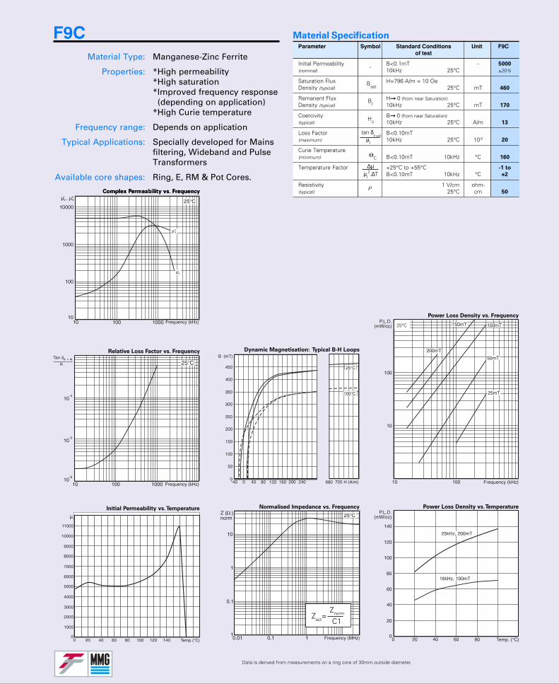
Parameter Symbol Standard Conditions Unit F9Cof test
Initial Permeability B<0.1mT - 5000
(nominal) 10kHz 25°C ±20%
Saturation Flux H=796 A/m = 10 OeDensity (typical) 25°C mT 460
Remanent Flux H 0 (from near Saturation)Density (typical) 10kHz 25°C mT 170
Coercivity B 0 (from near Saturation)(typical) 10kHz 25°C A/m 13
Loss Factor B<0.10mT(maximum) 10kHz 25°C 10-6 20
Curie Temperature(minimum) B<0.10mT 10kHz °C 160
Temperature Factor +25°C to +55°C -1 to
B<0.10mT 10kHz °C +2
Resistivity 1 V/cm ohm-(typical) 25°C cm 50
Bsat
Br
-
Hc
ΘC
Material Specification
ρComplex Permeability vs. Frequency
F9CMaterial Type: Manganese-Zinc Ferrite
Properties: *High permeability*High saturation*Improved frequency response
(depending on application)*High Curie temperature
Frequency range: Depends on application
Typical Applications: Specially developed for Mainsfiltering, Wideband and PulseTransformers
Available core shapes: Ring, E, RM & Pot Cores.∆µ
µi2.∆T
tan δ(r+e)
µi
Zact=Znorm
C1
Relative Loss Factor vs. Frequency
Initial Permeability vs. Temperature
Complex Permeability vs. Frequency
Dynamic Magnetisation: Typical B-H Loops
Data is derived from measurements on a ring core of 30mm outside diameter.
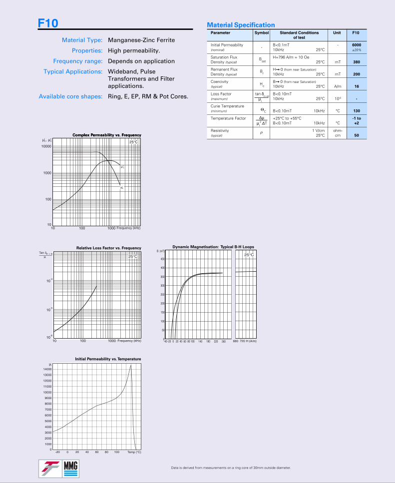
Parameter Symbol Standard Conditions Unit F10of test
Initial Permeability B<0.1mT - 6000
(nominal) 10kHz 25°C ±20%
Saturation Flux H=796 A/m = 10 OeDensity (typical) 25°C mT 380
Remanent Flux H 0 (from near Saturation)Density (typical) 10kHz 25°C mT 200
Coercivity B 0 (from near Saturation)(typical) 10kHz 25°C A/m 16
Loss Factor B<0.10mT(maximum) 10kHz 25°C 10-6 -
Curie Temperature(minimum) B<0.10mT 10kHz °C 130
Temperature Factor +25°C to +55°C -1 to
B<0.10mT 10kHz °C +2
Resistivity 1 V/cm ohm-(typical) 25°C cm 50
Bsat
Br
-
Hc
ΘC
Material Specification
ρComplex Permeability vs. Frequency
F10Material Type: Manganese-Zinc Ferrite
Properties: High permeability.
Frequency range: Depends on application
Typical Applications: Wideband, PulseTransformers and Filterapplications.
Available core shapes: Ring, E, EP, RM & Pot Cores.
∆µµi
2.∆T
tan δ(r+e)
µi
Initial Permeability vs. Temperature
Complex Permeability vs. Frequency
Dynamic Magnetisation: Typical B-H Loops
Data is derived from measurements on a ring core of 30mm outside diameter.
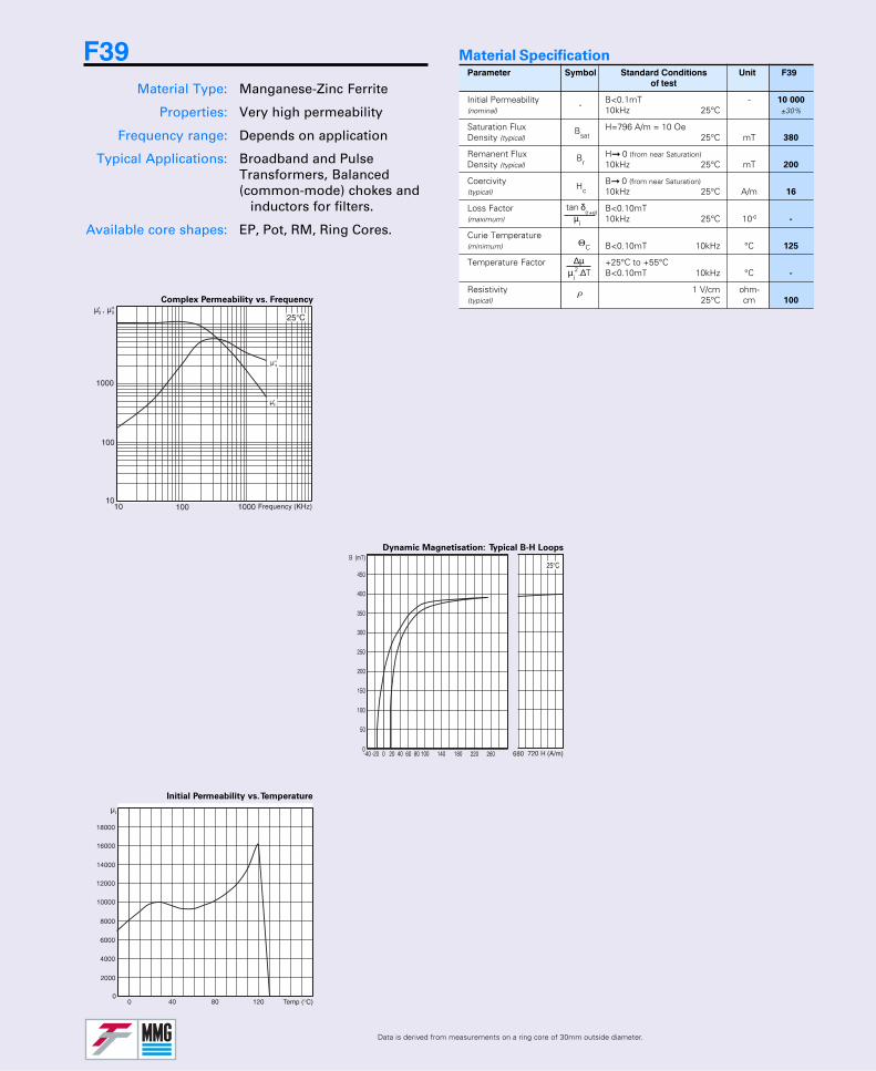
Parameter Symbol Standard Conditions Unit F39of test
Initial Permeability B<0.1mT - 10 000
(nominal) 10kHz 25°C ±30%
Saturation Flux H=796 A/m = 10 OeDensity (typical) 25°C mT 380
Remanent Flux H 0 (from near Saturation)Density (typical) 10kHz 25°C mT 200
Coercivity B 0 (from near Saturation)(typical) 10kHz 25°C A/m 16
Loss Factor B<0.10mT(maximum) 10kHz 25°C 10-6 -
Curie Temperature(minimum) B<0.10mT 10kHz °C 125
Temperature Factor +25°C to +55°CB<0.10mT 10kHz °C -
Resistivity 1 V/cm ohm-(typical) 25°C cm 100
Bsat
Br
-
Hc
ΘC
Material Specification
ρ
F39Material Type: Manganese-Zinc Ferrite
Properties: Very high permeability
Frequency range: Depends on application
Typical Applications: Broadband and PulseTransformers, Balanced(common-mode) chokes and
inductors for filters.
Available core shapes: EP, Pot, RM, Ring Cores.
∆µµi
2.∆T
tan δ(r+e)
µi

Parameter Symbol Standard Conditions Unit P11of test
Initial Permeability B<0.1mT - 2250
(nominal) 10kHz 25°C ±20%
Saturation Flux H=796 A/m = 10 OeDensity (typical) 25°C mT -
Remanent Flux H 0 (from near Saturation)Density (typical) 10kHz 25°C mT 70
Coercivity B 0 (from near Saturation)(typical) 10kHz 25°C A/m 18
Loss Factor B<0.10mT 10kHz 1.5
(maximum) 25°C 100kHz 10-6 5
Curie Temperature(minimum) B<0.10mT 10kHz °C 150
Hysteresis Material B from 1.5 to 3mT 10-6/Constant (maximum) 10kHz 25°C °C 0.8
Disaccommodation 10 to 100mins. 50°CFactor (maximum) B<0.25mT 10kHz 10-6 4
Temperature Factor +25°C to +55°C 0.5 to
B<0.10mT 10kHz °C 1.5
Resistivity 1 V/cm ohm-(typical) 25°C cm 100
Material Specification
Relative Loss Factor vs. Frequency
Initial Permeability vs. Temperature
Complex Permeability vs. Frequency
Dynamic Magnetisation: Typical B-H Loops
Data is derived from measurements on a ring core of 30mm outside diameter.
Bsat
Br
-
Hc
ΘC
ρ
ηB
µi2.log10(t2/t1)
∆µ
P11Material Type: Manganese-Zinc Ferrite
Properties: *High stability of inductance*Low temperature coefficient*Low loss factors*Medium permeability
Frequency range: Depends on application
Typical Applications: Filter networks and proximitydetectors
Available core shapes: RM and Pot Cores.
∆µµi
2.∆T
tan δ(r+e)
µi
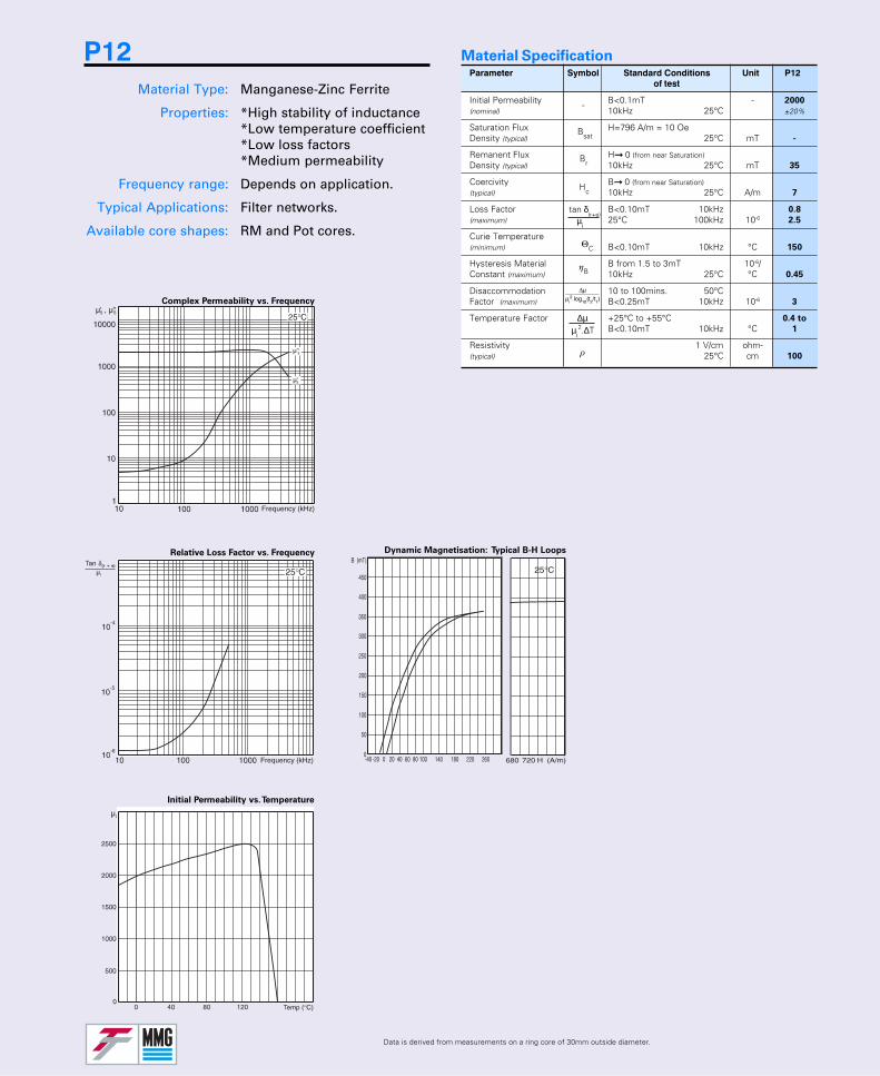
Parameter Symbol Standard Conditions Unit P12of test
Initial Permeability B<0.1mT - 2000
(nominal) 10kHz 25°C ±20%
Saturation Flux H=796 A/m = 10 OeDensity (typical) 25°C mT -
Remanent Flux H 0 (from near Saturation)Density (typical) 10kHz 25°C mT 35
Coercivity B 0 (from near Saturation)(typical) 10kHz 25°C A/m 7
Loss Factor B<0.10mT 10kHz 0.8
(maximum) 25°C 100kHz 10-6 2.5
Curie Temperature(minimum) B<0.10mT 10kHz °C 150
Hysteresis Material B from 1.5 to 3mT 10-6/Constant (maximum) 10kHz 25°C °C 0.45
Disaccommodation 10 to 100mins. 50°CFactor (maximum) B<0.25mT 10kHz 10-6 3
Temperature Factor +25°C to +55°C 0.4 to
B<0.10mT 10kHz °C 1
Resistivity 1 V/cm ohm-(typical) 25°C cm 100
Material Specification
Relative Loss Factor vs. Frequency
Initial Permeability vs. Temperature
Complex Permeability vs. Frequency
Dynamic Magnetisation: Typical B-H Loops
Data is derived from measurements on a ring core of 30mm outside diameter.
Bsat
Br
-
Hc
ΘC
ρ
ηB
µi2.log10(t2/t1)
∆µ
P12Material Type: Manganese-Zinc Ferrite
Properties: *High stability of inductance*Low temperature coefficient*Low loss factors*Medium permeability
Frequency range: Depends on application.
Typical Applications: Filter networks.
Available core shapes: RM and Pot cores.
∆µµi
2.∆T
tan δ(r+e)
µi
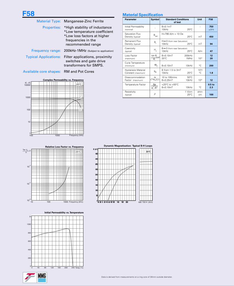
Parameter Symbol Standard Conditions Unit F58of test
Initial Permeability B<0.1mT - 750
(nominal) 10kHz 25°C ±20%
Saturation Flux H=796 A/m = 10 OeDensity (typical) 25°C mT 450
Remanent Flux H 0 (from near Saturation)Density (typical) 10kHz 25°C mT 94
Coercivity B 0 (from near Saturation)(typical) 10kHz 25°C A/m 47
Loss Factor B<0.10mT 200kHz 12
(maximum) 25°C 1MHz 10-6 20
Curie Temperature(minimum) B<0.10mT 10kHz °C 200
Hysteresis Material B from 1.5 to 3mT 10-6/Constant (maximum) 10kHz 25°C °C 1.8
Disaccommodation 10 to 100mins. 50°CFactor (maximum) B<0.25mT 10kHz 10-6 12
Temperature Factor +25°C to +55°C 0.5 to
B<0.10mT 10kHz °C 2.3
Resistivity 1 V/cm ohm-(typical) 25°C cm 100
Material Specification
Relative Loss Factor vs. Frequency
Initial Permeability vs. Temperature
Complex Permeability vs. Frequency
Dynamic Magnetisation: Typical B-H Loops
Data is derived from measurements on a ring core of 30mm outside diameter.
Bsat
Br
-
Hc
ΘC
ρ
ηB
µi2.log10(t2/t1)
∆µ
F58Material Type: Manganese-Zinc Ferrite
Properties: *High stability of inductance*Low temperature coefficient*Low loss factors at higherfrequencies in therecommended range
Frequency range: 200kHz-1MHz (Subject to application)
Typical Applications: Filter applications, proximityswitches and gate drive
transformers for SMPS.
Available core shapes: RM and Pot Cores
∆µµi
2.∆T
tan δ(r+e)
µi
Relative Loss Factor vs. Frequency
Initial Permeability vs. Temperature
Complex Permeability vs. Frequency
Data is derived from measurements on a ring core of 30mm outside diameter.
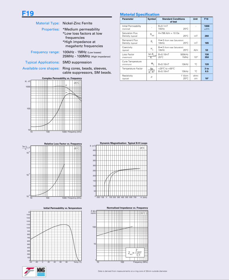
Parameter Symbol Standard Conditions Unit F19of test
Initial Permeability B<0.1mT - 1000
(nominal) 10kHz 25°C ±20%
Saturation Flux H=796 A/m = 10 OeDensity (typical) 25°C mT 260
Remanent Flux H 0 (from near Saturation)Density (typical) 10kHz 25°C mT 165
Coercivity B 0 (from near Saturation)(typical) 10kHz 25°C A/m 53
Loss Factor B<0.10mT 500kHz 130
(maximum) 25°C 1MHz 10-6 350
Curie Temperature(minimum) B<0.10mT 10kHz °C 120
Temperature Factor +25°C to +55°C 3 to
B<0.10mT 10kHz °C 6.5
Resistivity 1 V/cm ohm-(typical) 25°C cm 104
Bsat
Br
-
Hc
ΘC
Material Specification
ρ
Dynamic Magnetisation: Typical B-H Loops
Normalised Impedance vs. Frequency
F19Material Type: Nickel-Zinc Ferrite
Properties: *Medium permeability*Low loss factors at low
frequencies*High impedance at
megahertz frequencies
Frequency range: 100kHz - 1MHz (Low losses)
25MHz - 100MHz (High impedance)
Typical Applications: SMD suppression
Available core shapes: Ring cores, beads, sleeves,cable suppressors, SM beads.
Zact≈Znorm
C1
∆µµi
2.∆T
tan δ(r+e)
µi
Relative Loss Factor vs. Frequency
Initial Permeability vs. Temperature
Complex Permeability vs. Frequency
Dynamic Magnetisation: Typical B-H Loops
Data is derived from measurements on a ring core of 30mm outside diameter.
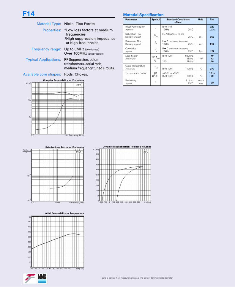
Parameter Symbol Standard Conditions Unit F14of test
Initial Permeability B<0.1mT - 220
(nominal) 10kHz 25°C ±20%
Saturation Flux H=796 A/m = 10 OeDensity (typical) 25°C mT 350
Remanent Flux H 0 (from near Saturation)Density (typical) 10kHz 25°C mT 217
Coercivity B 0 (from near Saturation)(typical) 10kHz 25°C A/m 172
Loss Factor B<0.10mT 500kHz 40
(maximum) 1MHz 10-6 42
25°c 2MHz 50
Curie Temperature(minimum) B<0.10mT 10kHz °C 270
Temperature Factor +25°C to +55°C 12 to
B<0.10mT 10kHz °C 30
Resistivity 1 V/cm ohm-(typical) 25°C cm 105
Bsat
Br
-
Hc
ΘC
Material Specification
ρ
F14Material Type: Nickel-Zinc Ferrite
Properties: *Low loss factors at mediumfrequencies
*High suppression impedanceat high frequencies
Frequency range: Up to 3MHz (Low losses)
Over 100MHz (Suppression)
Typical Applications: RF Suppression, baluntransformers, aerial rods,medium frequency tuned circuits.
Available core shapes: Rods, Chokes. ∆µµi
2.∆T
tan δ(r+e)
µi
Relative Loss Factor vs. Frequency
Initial Permeability vs. Temperature
Complex Permeability vs. Frequency
Dynamic Magnetisation: Typical B-H Loops
Data is derived from measurements on a ring core of 145x3.8x12mm (ODxIDxHT)
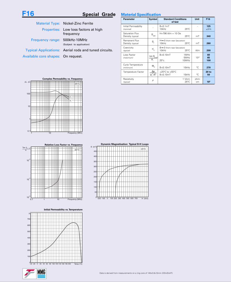
Parameter Symbol Standard Conditions Unit F16of test
Initial Permeability B<0.1mT - 125
(nominal) 10kHz 25°C ±20%
Saturation Flux H=796 A/m = 10 OeDensity (typical) 25°C mT 340
Remanent Flux H 0 (from near Saturation)Density (typical) 10kHz 25°C mT 260
Coercivity B 0 (from near Saturation)(typical) 10kHz 25°C A/m 200
Loss Factor B<0.10mT 1MHz 60
(maximum) 5MHz 10-6 65
25°c 10MHz 100
Curie Temperature(minimum) B<0.10mT 10kHz °C 270
Temperature Factor +25°C to +55°C 20 to
B<0.10mT 10kHz °C 50
Resistivity 1 V/cm ohm-(typical) 25°C cm 105
Bsat
Br
-
Hc
ΘC
Material Specification
ρ
F16 Special Grade
Material Type: Nickel-Zinc Ferrite
Properties: Low loss factors at highfrequency
Frequency range: 500kHz-10MHz(Subject to application)
Typical Applications: Aerial rods and tuned circuits.
Available core shapes: On request.
∆µµi
2.∆T
tan δ(r+e)
µi
Data is derived from measurements on a ring core of 14.5x3.8x12mm (OD x ID x HT)
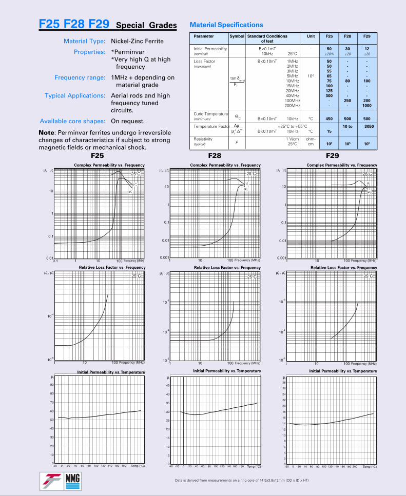
F25 F28 F29 Special Grades
Material Type: Nickel-Zinc Ferrite
Properties: *Perminvar*Very high Q at high
frequency
Frequency range: 1MHz + depending onmaterial grade
Typical Applications: Aerial rods and highfrequency tunedcircuits.
Available core shapes: On request.
Material Specifications
Note: Perminvar ferrites undergo irreversiblechanges of characteristics if subject to strongmagnetic fields or mechanical shock.
Complex Permeability vs. Frequency
Relative Loss Factor vs. Frequency
Initial Permeability vs. Temperature
Complex Permeability vs. Frequency
Relative Loss Factor vs. Frequency
Initial Permeability vs. Temperature
Complex Permeability vs. Frequency
Relative Loss Factor vs. Frequency
Initial Permeability vs. Temperature
F25 F28 F29
ΘC
ρ
Parameter Symbol Standard Conditions Unit F25 F28 F29of test
Initial Permeability B<0.1mT - 50 30 12
(nominal) 10kHz 25°C ±20% ±20 ±20
Loss Factor B<0.10mT 1MHz 50 - -
(maximum) 2MHz 50 - -
3MHz 55 - -
5MHz 10-6 65 - -
10MHz 75 80 100
15MHz 100 - -
20MHz 125 - -
40MHz 300 - -
100MHz - 250 200
200MHz - - 1000
Curie Temperature(minimum) B<0.10mT 10kHz °C 450 500 500
Temperature Factor +25°C to +55°C 10 to 3050
B<0.10mT 10kHz °C 15
Resistivity 1 V/cm ohm-(typical) 25°C cm 105 105 105
∆µµi
2.∆T
tan δ(r+e)
µi
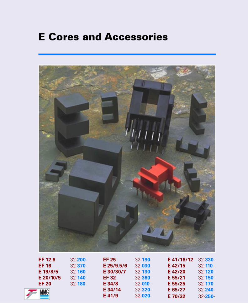
EF 25 32-190-E 25/9.5/6 32-030-E 30/30/7 32-130-EF 32 32-360-E 34/8 32-010-E 34/14 32-320-E 41/9 32-020-
E Cores and Accessories
E 41/16/12 32-330-E 42/15 32-110 -E 42/20 32-120-E 55/21 32-150-E 55/25 32-170-E 65/27 32-240-E 70/32 32-250-
EF 12.6 32-200-EF 16 32-370-E 19/8/5 32-160-E 20/10/5 32-140-EF 20 32-180-
E SeriesComponentsE SeriesComponents
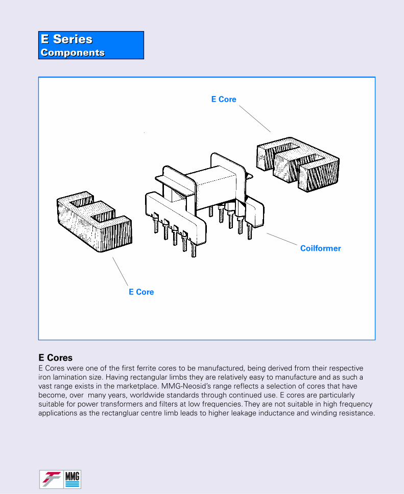
E CoresE Cores were one of the first ferrite cores to be manufactured, being derived from their respectiveiron lamination size. Having rectangular limbs they are relatively easy to manufacture and as such avast range exists in the marketplace. MMG-Neosid’s range reflects a selection of cores that havebecome, over many years, worldwide standards through continued use. E cores are particularlysuitable for power transformers and filters at low frequencies. They are not suitable in high frequencyapplications as the rectangluar centre limb leads to higher leakage inductance and winding resistance.
E Core
Coilformer
E Core
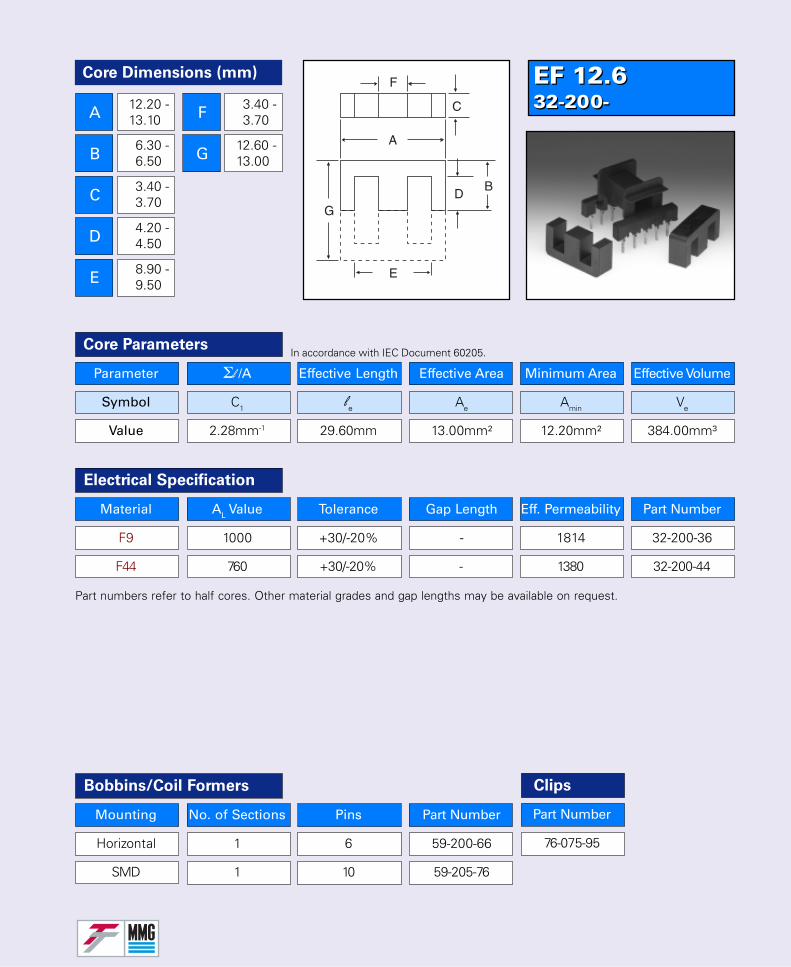
EF 12.632-200-EF 12.632-200-
Parameter Σl /A Effective Length Effective Area Minimum Area Effective Volume
Symbol C1 le Ae Amin Ve
Value 2.28mm-1 29.60mm 13.00mm² 12.20mm² 384.00mm³
Core Parameters
Material AL Value Tolerance Gap Length Eff. Permeability Part Number
F9 1000 +30/-20% - 1814 32-200-36
F44 760 +30/-20% - 1380 32-200-44
Electrical Specification
Part numbers refer to half cores. Other material grades and gap lengths may be available on request.
In accordance with IEC Document 60205.
Bobbins/Coil Formers
Mounting No. of Sections Pins Part Number
Horizontal 1 6 59-200-66
SMD 1 10 59-205-76
Core Dimensions (mm)
A
B
C
D
E
F
G
12.20 -13.10
6.30 -6.50
3.40 -3.70
4.20 -4.50
8.90 -9.50
3.40 -3.70
12.60 -13.00
Part Number
76-075-95
Clips

EF 1632-370-EF 1632-370-
Parameter Σl /A Effective Length Effective Area Minimum Area Effective Volume
Symbol C1 le Ae Amin Ve
Value 1.87mm-1 37.60mm 20.10mm² 19.40mm² 754.00mm³
Core Parameters
Material AL Value Tolerance Gap Length Eff. Permeability Part Number
F9 1400 +30/-20% - 2083 32-370-36
F44 960 +30/-20% - 1428 32-370-44
Electrical Specification
Part numbers refer to half cores. Other material grades and gap lengths may be available on request.
In accordance with IEC Document 60205.
Bobbins/Coil Formers
Mounting No. of Sections Pins Part Number
Horizontal 1 6 59-370-66
Vertical 1 6 59-375-66
Core Dimensions (mm)
A
B
C
D
E
F
G
15.50 -16.70
7.90 -8.20
4.30 -4.70
5.70 -6.10
11.30 -11.90
4.30 -4.70
15.80 -16.40
Part Number
76-076-95
Clips
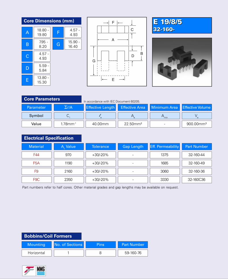
E 19/8/532-160-E 19/8/532-160-
Parameter Σl /A Effective Length Effective Area Minimum Area Effective Volume
Symbol C1 le Ae Amin Ve
Value 1.78mm-1 40.00mm 22.50mm² - 900.00mm³
Core Parameters
Material AL Value Tolerance Gap Length Eff. Permeability Part Number
F44 970 +30/-20% - 1375 32-160-44
F5A 1190 +30/-20% - 1685 32-160-49
F9 2160 +30/-20% - 3060 32-160-36
F9C 2350 +30/-20% - 3330 32-160C36
Electrical Specification
Bobbins/Coil Formers
Mounting No. of Sections Pins Part Number
Horizontal 1 8 59-160-76
Part numbers refer to half cores. Other material grades and gap lengths may be available on request.
In accordance with IEC Document 60205.
Core Dimensions (mm)
A
B
C
D
E
F
G
18.80 -19.80
7.95 -8.20
4.57 -4.93
5.59 -5.84
13.80 -15.30
4.57 -4.93
15.90 -16.40
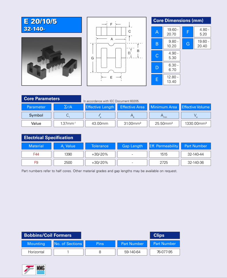
E 20/10/532-140-E 20/10/532-140-
Parameter Σl /A Effective Length Effective Area Minimum Area Effective Volume
Symbol C1 le Ae Amin Ve
Value 1.37mm-1 43.00mm 31.00mm² 25.50mm² 1330.00mm³
Core Parameters
Material AL Value Tolerance Gap Length Eff. Permeability Part Number
F44 1390 +30/-20% - 1515 32-140-44
F9 2500 +30/-20% - 2725 32-140-36
Electrical Specification
Part numbers refer to half cores. Other material grades and gap lengths may be available on request.
In accordance with IEC Document 60205.
Bobbins/Coil Formers
Mounting No. of Sections Pins Part Number
Horizontal 1 8 59-140-64
Core Dimensions (mm)
A
B
C
D
E
F
G
19.60 -20.70
9.80 -10.20
4.90 -5.30
6.30 -6.70
12.80 -13.40
4.80 -5.20
19.60 -20.40
Part Number
76-077-95
Clips
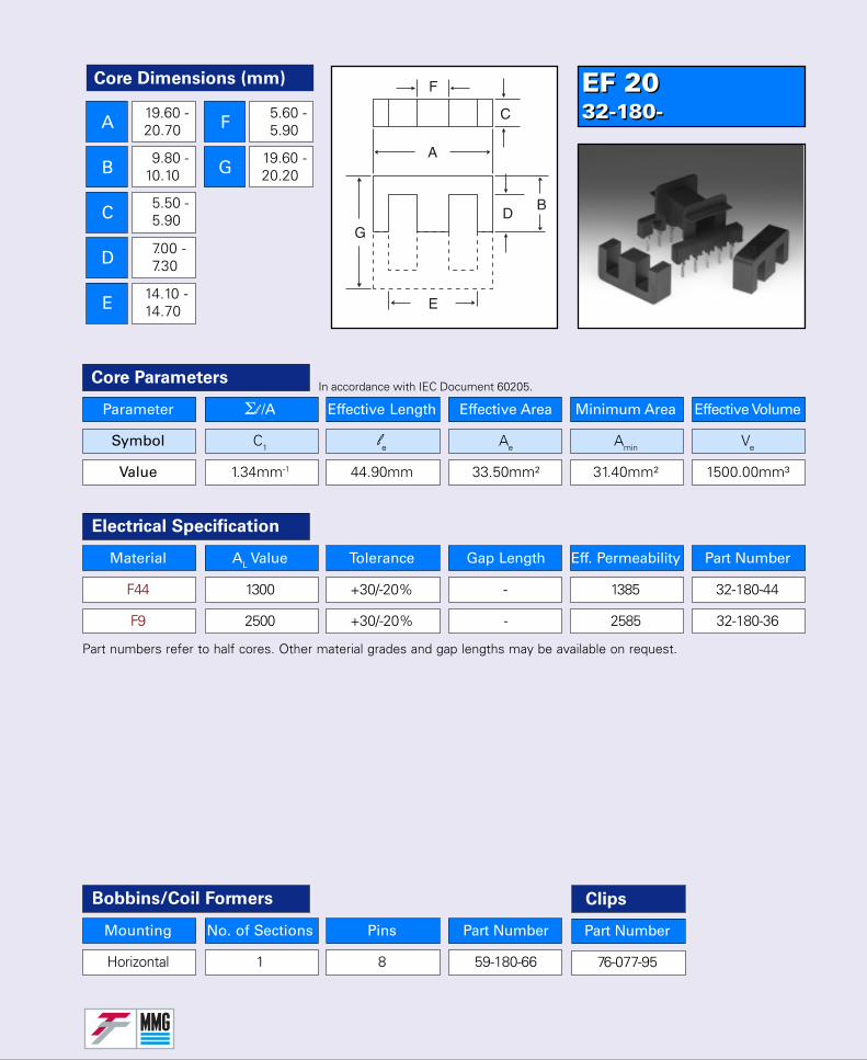
EF 2032-180-EF 2032-180-
Parameter Σl /A Effective Length Effective Area Minimum Area Effective Volume
Symbol C1 le Ae Amin Ve
Value 1.34mm-1 44.90mm 33.50mm² 31.40mm² 1500.00mm³
Core Parameters
Material AL Value Tolerance Gap Length Eff. Permeability Part Number
F44 1300 +30/-20% - 1385 32-180-44
F9 2500 +30/-20% - 2585 32-180-36
Electrical Specification
Bobbins/Coil Formers
Mounting No. of Sections Pins Part Number
Horizontal 1 8 59-180-66
Part numbers refer to half cores. Other material grades and gap lengths may be available on request.
In accordance with IEC Document 60205.
Part Number
76-077-95
Clips
Core Dimensions (mm)
A
B
C
D
E
F
G
19.60 -20.70
9.80 -10.10
5.50 -5.90
7.00 -7.30
14.10 -14.70
5.60 -5.90
19.60 -20.20
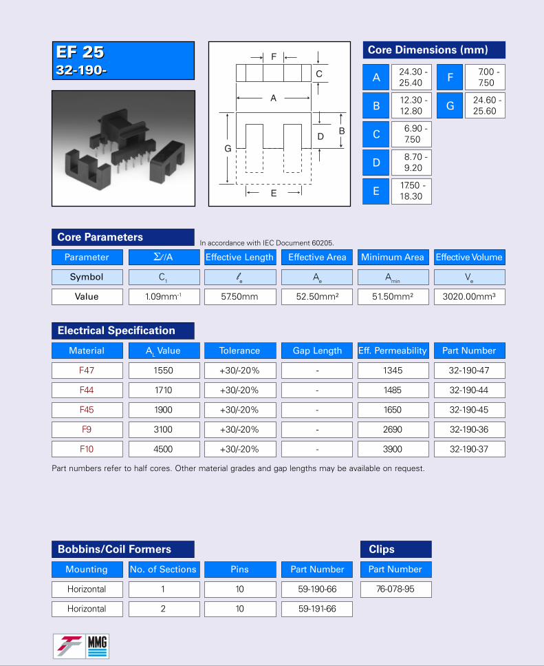
EF 2532-190-EF 2532-190-
Parameter Σl /A Effective Length Effective Area Minimum Area Effective Volume
Symbol C1 le Ae Amin Ve
Value 1.09mm-1 57.50mm 52.50mm² 51.50mm² 3020.00mm³
Core Parameters
Electrical Specification
Part numbers refer to half cores. Other material grades and gap lengths may be available on request.
In accordance with IEC Document 60205.
Bobbins/Coil Formers
Mounting No. of Sections Pins Part Number
Horizontal 1 10 59-190-66
Horizontal 2 10 59-191-66
Part Number
76-078-95
Clips
Material AL Value Tolerance Gap Length Eff. Permeability Part Number
F47 1550 +30/-20% - 1345 32-190-47
F44 1710 +30/-20% - 1485 32-190-44
F45 1900 +30/-20% - 1650 32-190-45
F9 3100 +30/-20% - 2690 32-190-36
F10 4500 +30/-20% - 3900 32-190-37
Core Dimensions (mm)
A
B
C
D
E
F
G
24.30 -25.40
12.30 -12.80
6.90 -7.50
8.70 -9.20
17.50 -18.30
7.00 -7.50
24.60 -25.60
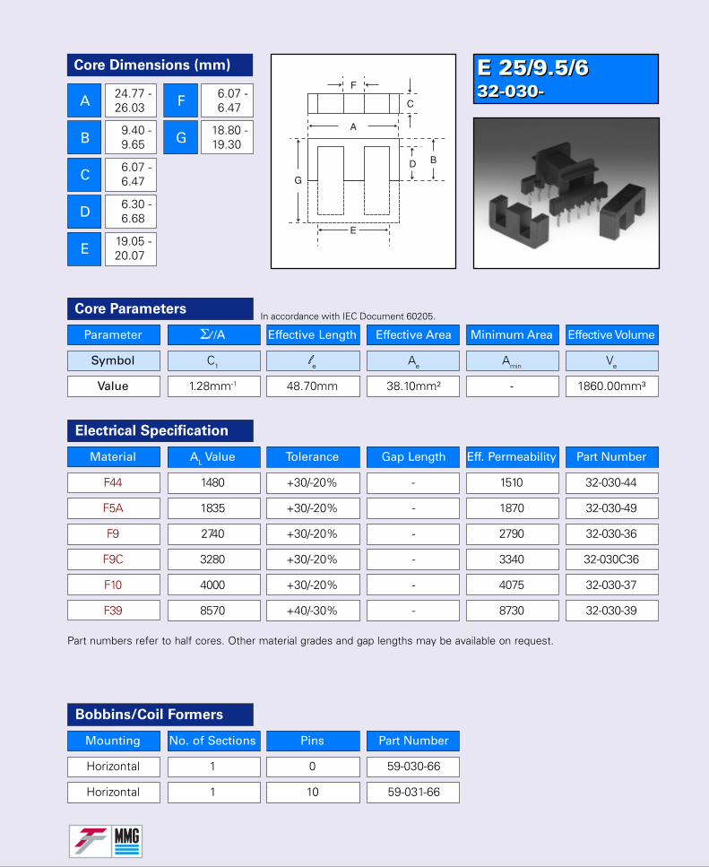
E 25/9.5/632-030-E 25/9.5/632-030-
Parameter Σl /A Effective Length Effective Area Minimum Area Effective Volume
Symbol C1 le Ae Amin Ve
Value 1.28mm-1 48.70mm 38.10mm² - 1860.00mm³
Core Parameters
Bobbins/Coil Formers
Mounting No. of Sections Pins Part Number
Horizontal 1 0 59-030-66
Horizontal 1 10 59-031-66
In accordance with IEC Document 60205.
Material AL Value Tolerance Gap Length Eff. Permeability Part Number
F44 1480 +30/-20% - 1510 32-030-44
F5A 1835 +30/-20% - 1870 32-030-49
F9 2740 +30/-20% - 2790 32-030-36
F9C 3280 +30/-20% - 3340 32-030C36
F10 4000 +30/-20% - 4075 32-030-37
F39 8570 +40/-30% - 8730 32-030-39
Electrical Specification
Part numbers refer to half cores. Other material grades and gap lengths may be available on request.
Core Dimensions (mm)
A
B
C
D
E
F
G
24.77 -26.03
9.40 -9.65
6.07 -6.47
6.30 -6.68
19.05 -20.07
6.07 -6.47
18.80 -19.30

E 30/30/732-130-E 30/30/732-130-
Electrical Specification
Part numbers refer to half cores. Other material grades and gap lengths may be available on request.
In accordance with IEC Document 60205.
Bobbins/Coil Formers
Mounting No. of Sections Pins Part Number
Horizontal 1 10 59-130-64
Horizontal 1 12 59-130-66
Material AL Value Tolerance Gap Length Eff. Permeability Part Number
F44 1800 +30/-20% - 1605 32-130-44
F45 1800 +30/-20% - 1605 32-130-45
F9 3300 +30/-20% - 2940 32-130-36
Core Parameters
Core Dimensions (mm)
A
B
C
D
E
F
G
29.40 -30.80
14.80 -15.20
6.80 -7.30
9.20 -9.70
19.50 -20.30
6.80 -7.20
29.60 -30.40
Parameter Σl /A Effective Length Effective Area Minimum Area Effective Volume
Symbol C1 le Ae Amin Ve
Value 1.12mm-1 67.00mm 60.00mm² - 4000.00mm³
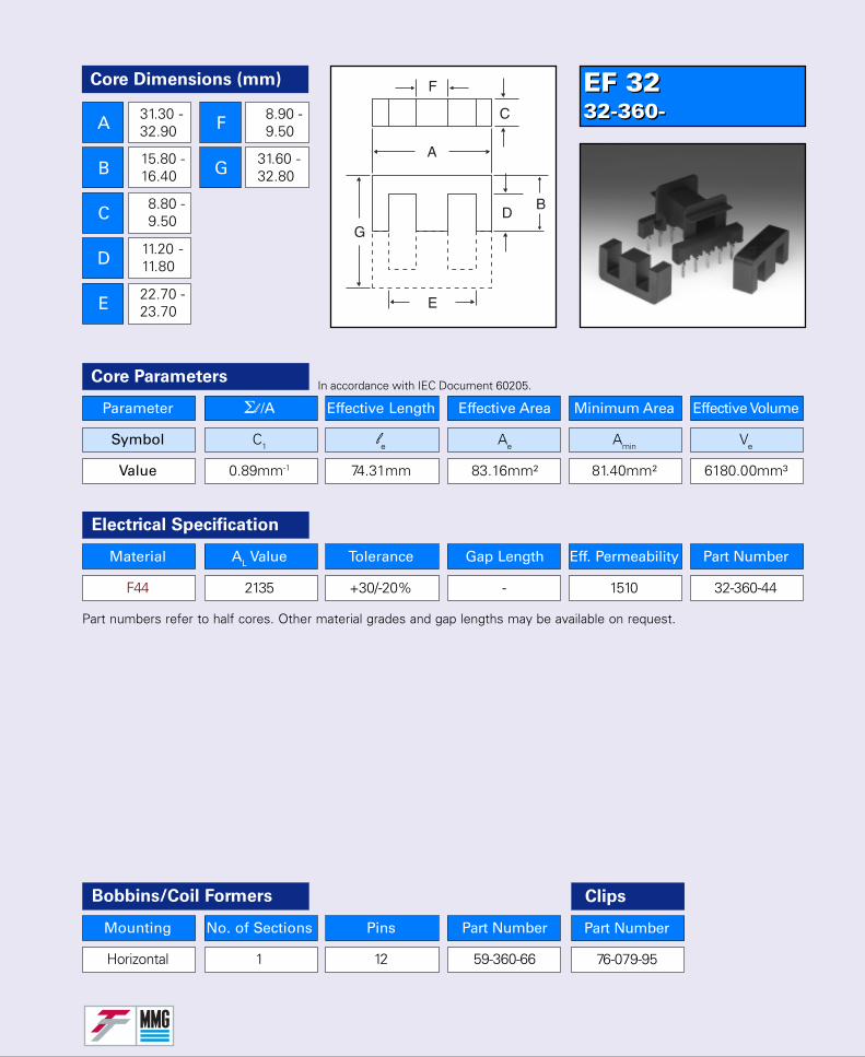
EF 3232-360-EF 3232-360-
Parameter Σl /A Effective Length Effective Area Minimum Area Effective Volume
Symbol C1 le Ae Amin Ve
Value 0.89mm-1 74.31mm 83.16mm² 81.40mm² 6180.00mm³
Core Parameters
Material AL Value Tolerance Gap Length Eff. Permeability Part Number
F44 2135 +30/-20% - 1510 32-360-44
Electrical Specification
Bobbins/Coil Formers
Mounting No. of Sections Pins Part Number
Horizontal 1 12 59-360-66
Part numbers refer to half cores. Other material grades and gap lengths may be available on request.
In accordance with IEC Document 60205.
Part Number
76-079-95
Clips
Core Dimensions (mm)
A
B
C
D
E
F
G
31.30 -32.90
15.80 -16.40
8.80 -9.50
11.20 -11.80
22.70 -23.70
8.90 -9.50
31.60 -32.80
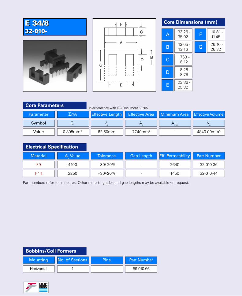
E 34/832-010-E 34/832-010-
Parameter Σl /A Effective Length Effective Area Minimum Area Effective Volume
Symbol C1 le Ae Amin Ve
Value 0.808mm-1 62.50mm 77.40mm² - 4840.00mm³
Core Parameters
Electrical Specification
Part numbers refer to half cores. Other material grades and gap lengths may be available on request.
In accordance with IEC Document 60205.
Bobbins/Coil Formers
Material AL Value Tolerance Gap Length Eff. Permeability Part Number
F9 4100 +30/-20% - 2640 32-010-36
F44 2250 +30/-20% - 1450 32-010-44
Mounting No. of Sections Pins Part Number
Horizontal 1 - 59-010-66
Core Dimensions (mm)
A
B
C
D
E
F
G
33.26 -35.02
13.05 -13.16
7.63 -8.12
8.28 -8.78
23.86 -25.32
10.81 -11.45
26.10 -26.32

E 34/14 (US E375)32-320-E 34/14 (US E375)32-320-
Parameter Σl /A Effective Length Effective Area Minimum Area Effective Volume
Symbol C1 le Ae Amin Ve
Value 0.79mm-1 69.17mm 87.96mm² - 6084.00mm³
Core Parameters
Material AL Value Tolerance Gap Length Eff. Permeability Part Number
F44 2380 +30/-20% - 1490 32-320-44
F5A 2890 +25/-25% - 1810 32-320-49
F9C 4800 +30/-20% - 30200 32-320C36
Electrical Specification
Part numbers refer to half cores. Other material grades and gap lengths may be available on request.
In accordance with IEC Document 60205.
Core Dimensions (mm)
A
B
C
D
E
F
G
34.16 -35.20
14.27 -14.53
9.02 -9.52
9.53 -9.77
25.02 min.
9.27 -9.53
18.54 -19.06
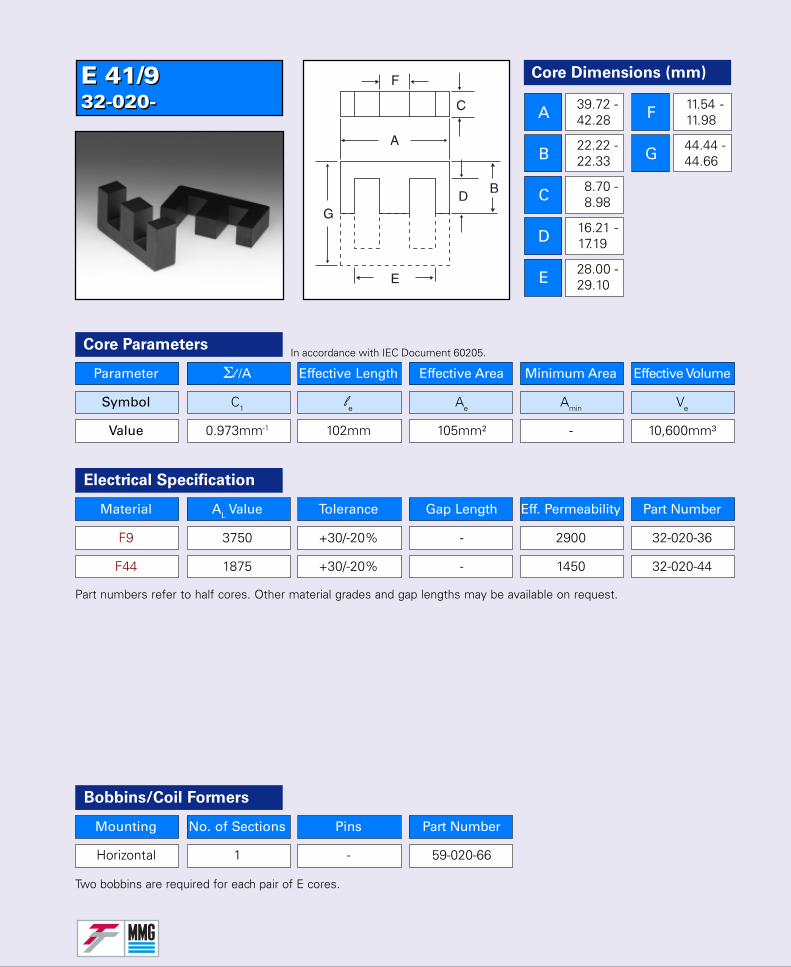
E 41/932-020-E 41/932-020-
Parameter Σl /A Effective Length Effective Area Minimum Area Effective Volume
Symbol C1 le Ae Amin Ve
Value 0.973mm-1 102mm 105mm² - 10,600mm³
Core Parameters
Electrical Specification
Part numbers refer to half cores. Other material grades and gap lengths may be available on request.
In accordance with IEC Document 60205.
Bobbins/Coil Formers
Material AL Value Tolerance Gap Length Eff. Permeability Part Number
F9 3750 +30/-20% - 2900 32-020-36
F44 1875 +30/-20% - 1450 32-020-44
Mounting No. of Sections Pins Part Number
Horizontal 1 - 59-020-66
Two bobbins are required for each pair of E cores.
Core Dimensions (mm)
A
B
C
D
E
F
G
39.72 -42.28
22.22 -22.33
8.70 -8.98
16.21 -17.19
28.00 -29.10
11.54 -11.98
44.44 -44.66
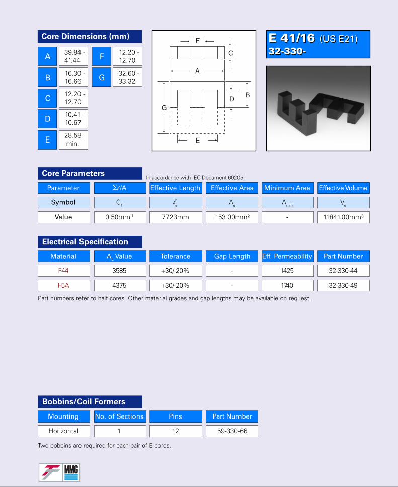
E 41/16 (US E21)32-330-E 41/16 (US E21)32-330-
Parameter Σl /A Effective Length Effective Area Minimum Area Effective Volume
Symbol C1 le Ae Amin Ve
Value 0.50mm-1 77.23mm 153.00mm² - 11841.00mm³
Core Parameters
Material AL Value Tolerance Gap Length Eff. Permeability Part Number
F44 3585 +30/-20% - 1425 32-330-44
F5A 4375 +30/-20% - 1740 32-330-49
Electrical Specification
Part numbers refer to half cores. Other material grades and gap lengths may be available on request.
In accordance with IEC Document 60205.
Core Dimensions (mm)
A
B
C
D
E
F
G
39.84 -41.44
16.30 -16.66
12.20 -12.70
10.41 -10.67
28.58 min.
12.20 -12.70
32.60 -33.32
Bobbins/Coil Formers
Mounting No. of Sections Pins Part Number
Horizontal 1 12 59-330-66
Two bobbins are required for each pair of E cores.
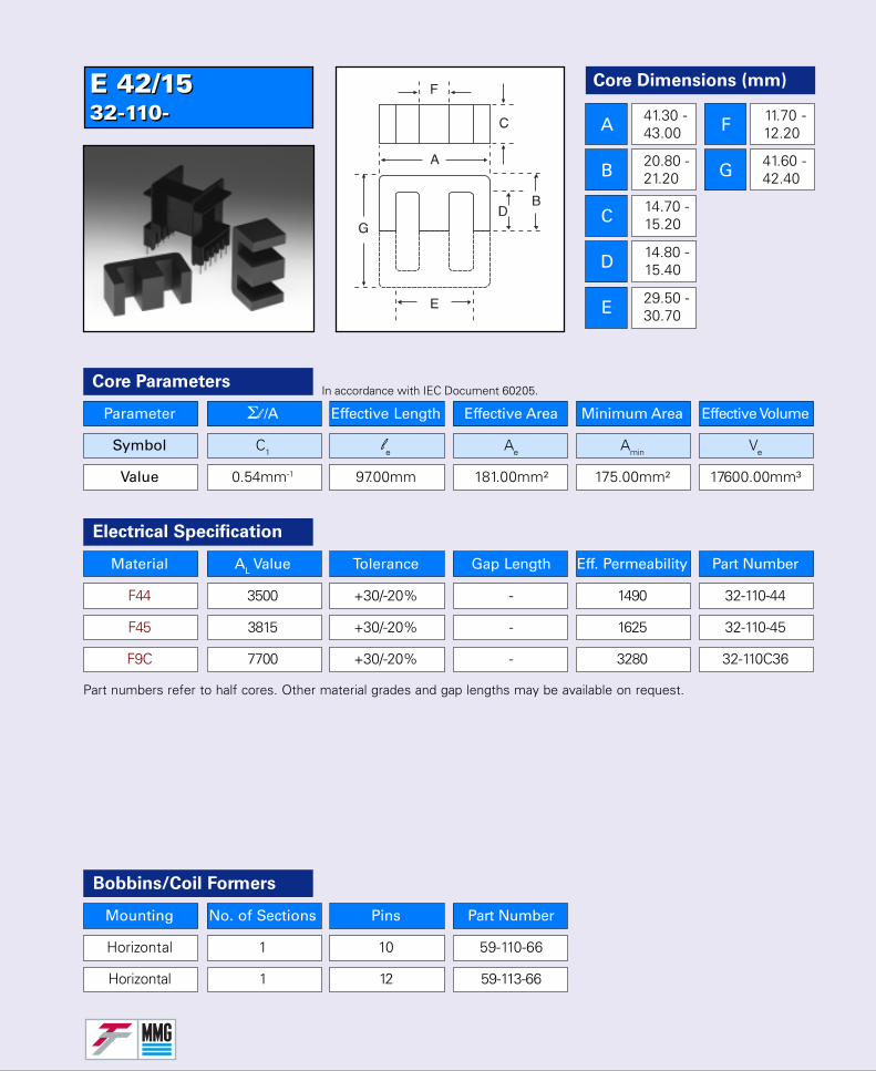
E 42/1532-110-E 42/1532-110-
Parameter Σl /A Effective Length Effective Area Minimum Area Effective Volume
Symbol C1 le Ae Amin Ve
Value 0.54mm-1 97.00mm 181.00mm² 175.00mm² 17600.00mm³
Core Parameters
Material AL Value Tolerance Gap Length Eff. Permeability Part Number
F44 3500 +30/-20% - 1490 32-110-44
F45 3815 +30/-20% - 1625 32-110-45
F9C 7700 +30/-20% - 3280 32-110C36
Electrical Specification
Part numbers refer to half cores. Other material grades and gap lengths may be available on request.
In accordance with IEC Document 60205.
Bobbins/Coil Formers
Mounting No. of Sections Pins Part Number
Horizontal 1 10 59-110-66
Horizontal 1 12 59-113-66
Core Dimensions (mm)
A
B
C
D
E
F
G
41.30 -43.00
20.80 -21.20
14.70 -15.20
14.80 -15.40
29.50 -30.70
11.70 -12.20
41.60 -42.40

E 42/2032-120-E 42/2032-120-
Parameter Σl /A Effective Length Effective Area Minimum Area Effective Volume
Symbol C1 le Ae Amin Ve
Value 0.41mm-1 97.00mm 240.00mm² 232.00mm² 23300.00mm³
Core Parameters
Material AL Value Tolerance Gap Length Eff. Permeability Part Number
F44 4560 +30/-20% - 1470 32-120-44
Electrical Specification
Bobbins/Coil Formers
Mounting No. of Sections Pins Part Number
Horizontal 1 12 59-120-66
Part numbers refer to half cores. Other material grades and gap lengths may be available on request.
In accordance with IEC Document 60205.
Core Dimensions (mm)
A
B
C
D
E
F
G
41.30 -43.00
20.80 -21.20
19.40 -20.00
14.80 -15.40
29.40 -30.70
11.70 -12.20
41.60 -42.40
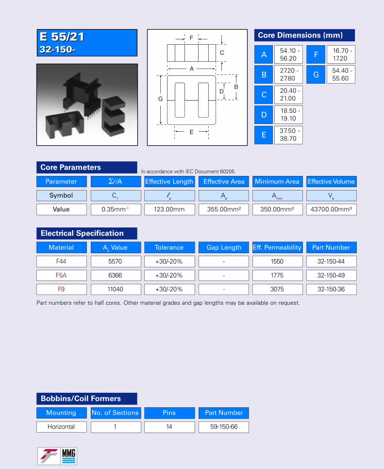
E 55/2132-150-E 55/2132-150-
Parameter Σl /A Effective Length Effective Area Minimum Area Effective Volume
Symbol C1 le Ae Amin Ve
Value 0.35mm-1 123.00mm 355.00mm² 350.00mm² 43700.00mm³
Core Parameters
Material AL Value Tolerance Gap Length Eff. Permeability Part Number
F44 5570 +30/-20% - 1550 32-150-44
F5A 6366 +30/-20% - 1775 32-150-49
F9 11040 +30/-20% - 3075 32-150-36
Electrical Specification
Part numbers refer to half cores. Other material grades and gap lengths may be available on request.
In accordance with IEC Document 60205.
Bobbins/Coil Formers
Mounting No. of Sections Pins Part Number
Horizontal 1 14 59-150-66
Core Dimensions (mm)
A
B
C
D
E
F
G
54.10 -56.20
27.20 -27.80
20.40 -21.00
18.50 -19.10
37.50 -38.70
16.70 -17.20
54.40 -55.60
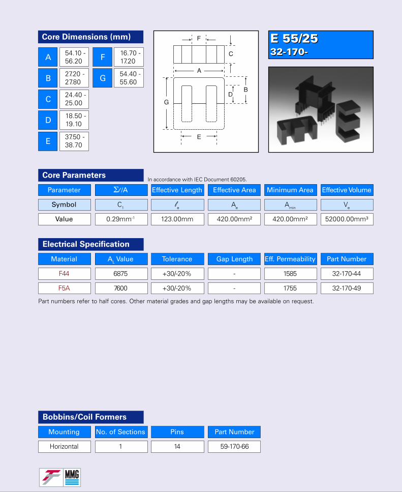
E 55/2532-170-E 55/2532-170-
Parameter Σl /A Effective Length Effective Area Minimum Area Effective Volume
Symbol C1 le Ae Amin Ve
Value 0.29mm-1 123.00mm 420.00mm² 420.00mm² 52000.00mm³
Core Parameters
Material AL Value Tolerance Gap Length Eff. Permeability Part Number
F44 6875 +30/-20% - 1585 32-170-44
F5A 7600 +30/-20% - 1755 32-170-49
Electrical Specification
Bobbins/Coil Formers
Mounting No. of Sections Pins Part Number
Horizontal 1 14 59-170-66
Part numbers refer to half cores. Other material grades and gap lengths may be available on request.
In accordance with IEC Document 60205.
Core Dimensions (mm)
A
B
C
D
E
F
G
54.10 -56.20
27.20 -27.80
24.40 -25.00
18.50 -19.10
37.50 -38.70
16.70 -17.20
54.40 -55.60
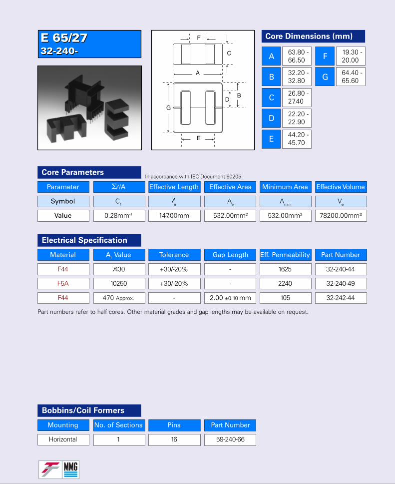
E 65/2732-240-E 65/2732-240-
Parameter Σl /A Effective Length Effective Area Minimum Area Effective Volume
Symbol C1 le Ae Amin Ve
Value 0.28mm-1 147.00mm 532.00mm² 532.00mm² 78200.00mm³
Core Parameters
Material AL Value Tolerance Gap Length Eff. Permeability Part Number
F44 7430 +30/-20% - 1625 32-240-44
F5A 10250 +30/-20% - 2240 32-240-49
F44 470 Approx. - 2.00 ±0.10 mm 105 32-242-44
Electrical Specification
Part numbers refer to half cores. Other material grades and gap lengths may be available on request.
In accordance with IEC Document 60205.
Bobbins/Coil Formers
Mounting No. of Sections Pins Part Number
Horizontal 1 16 59-240-66
Core Dimensions (mm)
A
B
C
D
E
F
G
63.80 -66.50
32.20 -32.80
26.80 -27.40
22.20 -22.90
44.20 -45.70
19.30 -20.00
64.40 -65.60
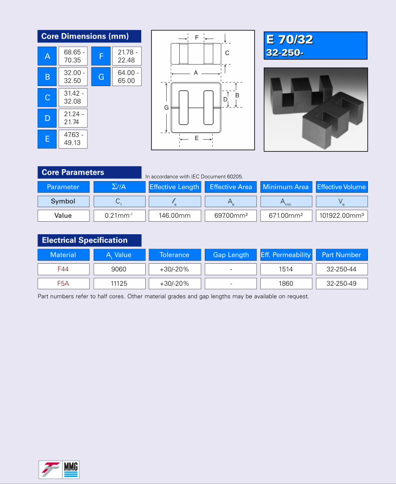
E 70/3232-250-E 70/3232-250-
Parameter Σl /A Effective Length Effective Area Minimum Area Effective Volume
Symbol C1 le Ae Amin Ve
Value 0.21mm-1 146.00mm 697.00mm² 671.00mm² 101922.00mm³
Core Parameters
Material AL Value Tolerance Gap Length Eff. Permeability Part Number
F44 9060 +30/-20% - 1514 32-250-44
F5A 11125 +30/-20% - 1860 32-250-49
Electrical Specification
Part numbers refer to half cores. Other material grades and gap lengths may be available on request.
In accordance with IEC Document 60205.
Core Dimensions (mm)
A
B
C
D
E
F
G
68.65 -70.35
32.00 -32.50
31.42 -32.08
21.24 -21.74
47.63 -49.13
21.78 -22.48
64.00 -65.00
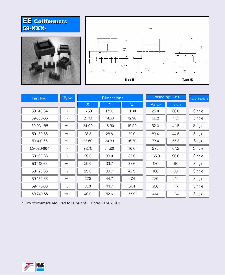
EE Coilformers59-XXX-EE Coilformers59-XXX-
No. of sectionsPart No. Type Dimensions
‘X’ ‘Y’ ‘Z’
Winding Data
AN (mm²)
* Two coilformers required for a pair of E Cores. 32-020-XX
IN (mm)
Type H1
‘X’
‘Z’
‘Y’
‘PL’‘PO’ ‘X’
‘Z’
Type H3
59-140-64 H1 17.50 17.50 11.80 25.0 30.0 Single
59-030-66 H4 21.10 18.60 12.90 56.2 41.0 Single
59-031-66 H1 24.00 18.90 19.90 52.3 41.8 Single
59-130-66 H1 28.8 28.8 20.0 83.4 44.8 Single
59-010-66 H4 23.60 20.30 16.20 73.4 55.3 Single
59-020-66* H4 27.70 24.90 16.0 97.3 61.2 Single
59-100-66 H1 29.0 38.0 35.0 165.0 90.0 Single
59-113-66 H3 29.0 39.7 38.6 180 88 Single
59-120-66 H3 29.0 39.7 42.9 180 98 Single
59-150-66 H3 37.0 44.7 47.4 280 110 Single
59-170-66 H3 37.0 44.7 51.4 280 117 Single
59-240-66 H3 40.0 52.6 55.9 414 134 Single
Material
No. of
Clip Part Number
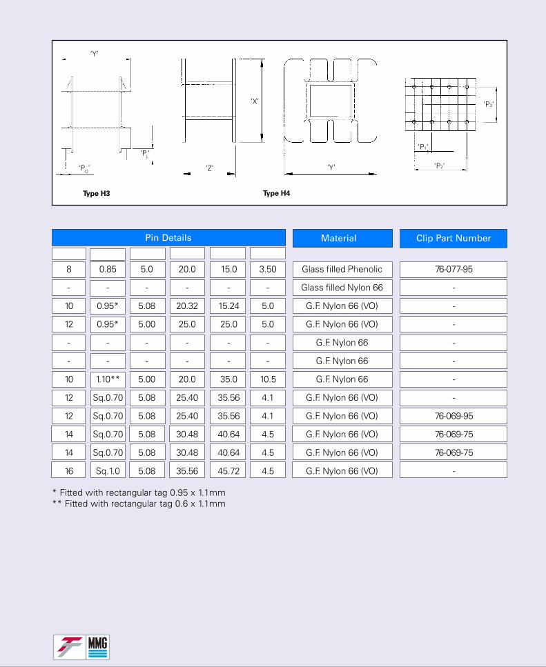
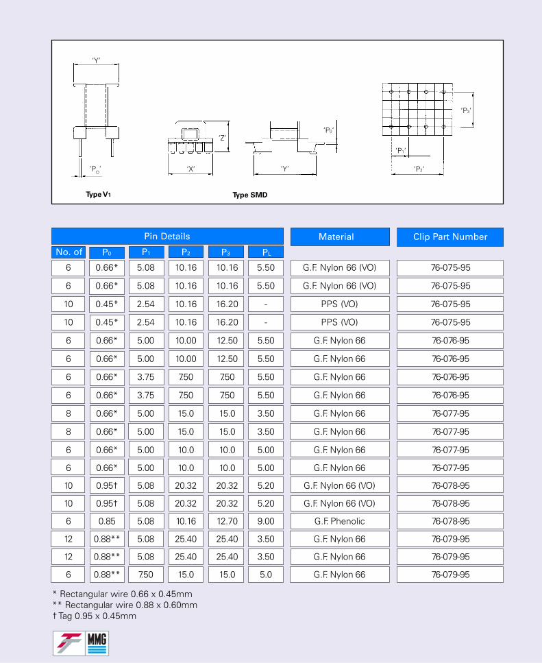
P1 P2 P3 PL
Pin Details
P0
* Fitted with rectangular tag 0.95 x 1.1mm** Fitted with rectangular tag 0.6 x 1.1mm
Type H3
‘Y’
‘PO’
‘PL’
‘Z’
‘X’
‘Y’ ‘P2‘
‘P1’
‘P3’
Type H4
8 0.85 5.0 20.0 15.0 3.50 Glass filled Phenolic 76-077-95
- - - - - - Glass filled Nylon 66 -
10 0.95* 5.08 20.32 15.24 5.0 G.F. Nylon 66 (VO) -
12 0.95* 5.00 25.0 25.0 5.0 G.F. Nylon 66 (VO) -
- - - - - - G.F. Nylon 66 -
- - - - - - G.F. Nylon 66 -
10 1.10** 5.00 20.0 35.0 10.5 G.F. Nylon 66 -
12 Sq.0.70 5.08 25.40 35.56 4.1 G.F. Nylon 66 (VO) -
12 Sq.0.70 5.08 25.40 35.56 4.1 G.F. Nylon 66 (VO) 76-069-95
14 Sq.0.70 5.08 30.48 40.64 4.5 G.F. Nylon 66 (VO) 76-069-75
14 Sq.0.70 5.08 30.48 40.64 4.5 G.F. Nylon 66 (VO) 76-069-75
16 Sq.1.0 5.08 35.56 45.72 4.5 G.F. Nylon 66 (VO) -
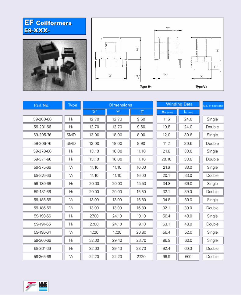
EF Coilformers59-XXX-EF Coilformers59-XXX-
No. of sectionsPart No. Type Dimensions
‘X’ ‘Y’ ‘Z’
Winding Data
AN (mm²) IN (mm)
59-200-66 H1 12.70 12.70 9.60 11.6 24.0 Single
59-201-66 H1 12.70 12.70 9.60 10.8 24.0 Double
59-205-76 SMD 13.00 18.00 8.90 12.0 30.6 Single
Type H1
‘X’
‘Z’
‘Y’
‘PL’‘PO’ ‘X’
Type V1
‘Z’
‘PL’
59-206-76 SMD 13.00 18.00 8.90 11.2 30.6 Double
59-370-66 H1 13.10 16.00 11.10 21.6 33.0 Single
59-371-66 H1 13.10 16.00 11.10 20.10 33.0 Double
59-375-66 V1 11.10 11.10 16.00 21.6 33.0 Single
59-376-66 V1 11.10 11.10 16.00 20.1 33.0 Double
59-180-66 H1 20.00 20.00 15.50 34.8 39.0 Single
59-181-66 H1 20.00 20.00 15.50 32.1 39.0 Double
59-185-66 V1 13.90 13.90 16.80 34.8 39.0 Single
59-186-66 V1 13.90 13.90 16.80 32.1 39.0 Double
59-190-66 H1 27.00 24.10 19.10 56.4 48.0 Single
59-191-66 H1 27.00 24.10 19.10 53.1 48.0 Double
59-196-64 V1 17.20 17.20 20.80 56.4 52.0 Single
59-360-66 H1 32.00 29.40 23.70 96.9 60.0 Single
59-361-66 H1 32.00 29.40 23.70 92.4 60.0 Double
59-365-66 V1 22.20 22.20 27.20 96.9 600 Double
Material
No. of
Clip Part Number
P1 P2 P3 PL
Pin Details
P0
* Rectangular wire 0.66 x 0.45mm** Rectangular wire 0.88 x 0.60mm† Tag 0.95 x 0.45mm
Type V1
‘Z’
‘X’ ‘Y’ ‘P2‘
‘P1’
‘P3’
‘P0‘
Type SMD
‘Y’
‘PO’
6 0.66* 5.08 10.16 10.16 5.50 G.F. Nylon 66 (VO) 76-075-95
6 0.66* 5.08 10.16 10.16 5.50 G.F. Nylon 66 (VO) 76-075-95
10 0.45* 2.54 10.16 16.20 - PPS (VO) 76-075-95
10 0.45* 2.54 10.16 16.20 - PPS (VO) 76-075-95
6 0.66* 5.00 10.00 12.50 5.50 G.F. Nylon 66 76-076-95
6 0.66* 5.00 10.00 12.50 5.50 G.F. Nylon 66 76-076-95
6 0.66* 3.75 7.50 7.50 5.50 G.F. Nylon 66 76-076-95
6 0.66* 3.75 7.50 7.50 5.50 G.F. Nylon 66 76-076-95
8 0.66* 5.00 15.0 15.0 3.50 G.F. Nylon 66 76-077-95
8 0.66* 5.00 15.0 15.0 3.50 G.F. Nylon 66 76-077-95
6 0.66* 5.00 10.0 10.0 5.00 G.F. Nylon 66 76-077-95
6 0.66* 5.00 10.0 10.0 5.00 G.F. Nylon 66 76-077-95
10 0.95† 5.08 20.32 20.32 5.20 G.F. Nylon 66 (VO) 76-078-95
10 0.95† 5.08 20.32 20.32 5.20 G.F. Nylon 66 (VO) 76-078-95
6 0.85 5.08 10.16 12.70 9.00 G.F. Phenolic 76-078-95
12 0.88** 5.08 25.40 25.40 3.50 G.F. Nylon 66 76-079-95
12 0.88** 5.08 25.40 25.40 3.50 G.F. Nylon 66 76-079-95
6 0.88** 7.50 15.0 15.0 5.0 G.F. Nylon 66 76-079-95
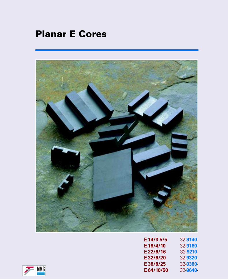
Planar E Cores
E 14/3.5/5 32-9140-E 18/4/10 32-9180-E 22/6/16 32-9210-E 32/6/20 32-9320-E 38/8/25 32-9380-E 64/10/50 32-9640-
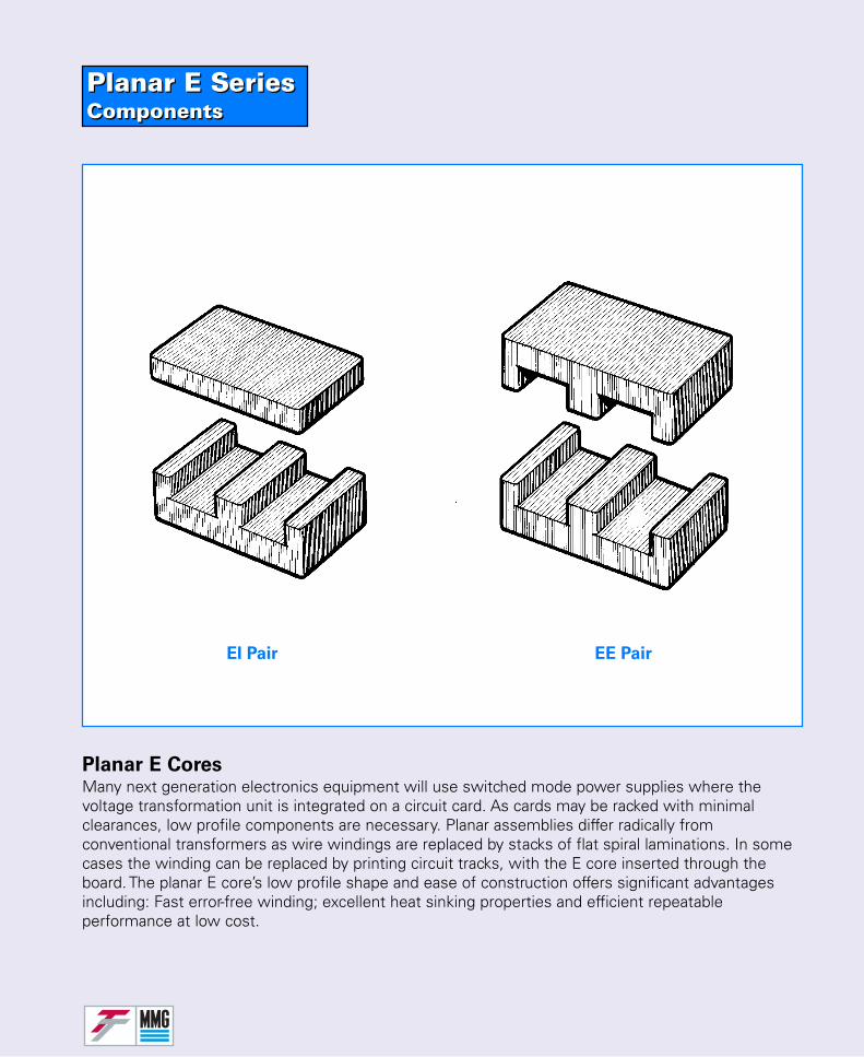
Planar E SeriesComponentsPlanar E SeriesComponents
Planar E CoresMany next generation electronics equipment will use switched mode power supplies where thevoltage transformation unit is integrated on a circuit card. As cards may be racked with minimalclearances, low profile components are necessary. Planar assemblies differ radically fromconventional transformers as wire windings are replaced by stacks of flat spiral laminations. In somecases the winding can be replaced by printing circuit tracks, with the E core inserted through theboard. The planar E core’s low profile shape and ease of construction offers significant advantagesincluding: Fast error-free winding; excellent heat sinking properties and efficient repeatableperformance at low cost.
EE PairEI Pair
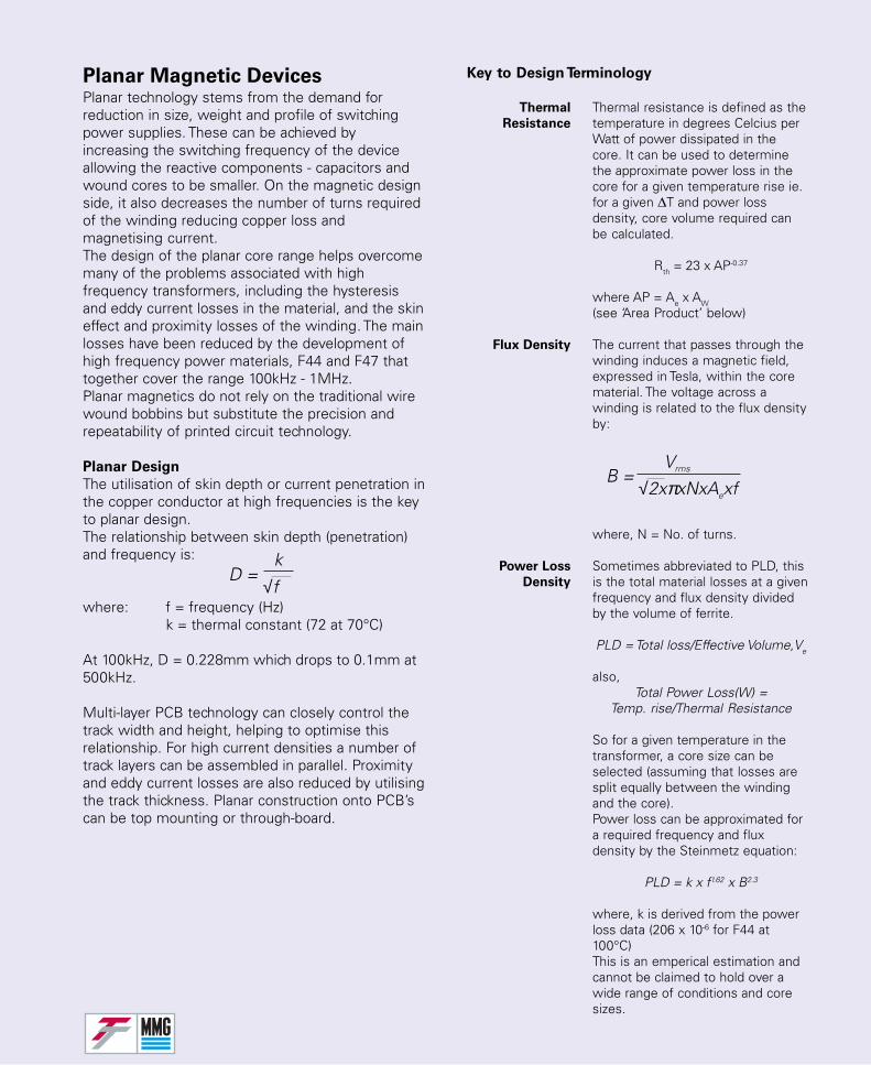
Planar Magnetic DevicesPlanar technology stems from the demand forreduction in size, weight and profile of switchingpower supplies. These can be achieved byincreasing the switching frequency of the deviceallowing the reactive components - capacitors andwound cores to be smaller. On the magnetic designside, it also decreases the number of turns requiredof the winding reducing copper loss andmagnetising current.The design of the planar core range helps overcomemany of the problems associated with highfrequency transformers, including the hysteresisand eddy current losses in the material, and the skineffect and proximity losses of the winding. The mainlosses have been reduced by the development ofhigh frequency power materials, F44 and F47 thattogether cover the range 100kHz - 1MHz.Planar magnetics do not rely on the traditional wirewound bobbins but substitute the precision andrepeatability of printed circuit technology.
Planar Design
The utilisation of skin depth or current penetration inthe copper conductor at high frequencies is the keyto planar design.The relationship between skin depth (penetration)and frequency is:
where: f = frequency (Hz)k = thermal constant (72 at 70°C)
At 100kHz, D = 0.228mm which drops to 0.1mm at500kHz.
Multi-layer PCB technology can closely control thetrack width and height, helping to optimise thisrelationship. For high current densities a number oftrack layers can be assembled in parallel. Proximityand eddy current losses are also reduced by utilisingthe track thickness. Planar construction onto PCB’scan be top mounting or through-board.
Key to Design Terminology
Thermal Thermal resistance is defined as theResistance temperature in degrees Celcius per
Watt of power dissipated in thecore. It can be used to determinethe approximate power loss in thecore for a given temperature rise ie.for a given ∆T and power lossdensity, core volume required canbe calculated.
Rth = 23 x AP-0.37
where AP = Ae x AW(see ‘Area Product’ below)
Flux Density The current that passes through thewinding induces a magnetic field,expressed in Tesla, within the corematerial. The voltage across awinding is related to the flux densityby:
where, N = No. of turns.
Power Loss Sometimes abbreviated to PLD, thisDensity is the total material losses at a given
frequency and flux density dividedby the volume of ferrite.
PLD = Total loss/Effective Volume,Ve
also,Total Power Loss(W) =
Temp. rise/Thermal Resistance
So for a given temperature in thetransformer, a core size can beselected (assuming that losses aresplit equally between the windingand the core).Power loss can be approximated fora required frequency and fluxdensity by the Steinmetz equation:
PLD = k x f1.62 x B2.3
where, k is derived from the powerloss data (206 x 10-6 for F44 at100°C)This is an emperical estimation andcannot be claimed to hold over awide range of conditions and coresizes.
B = √2xπxNxAexf
Vrms
D = √f
k
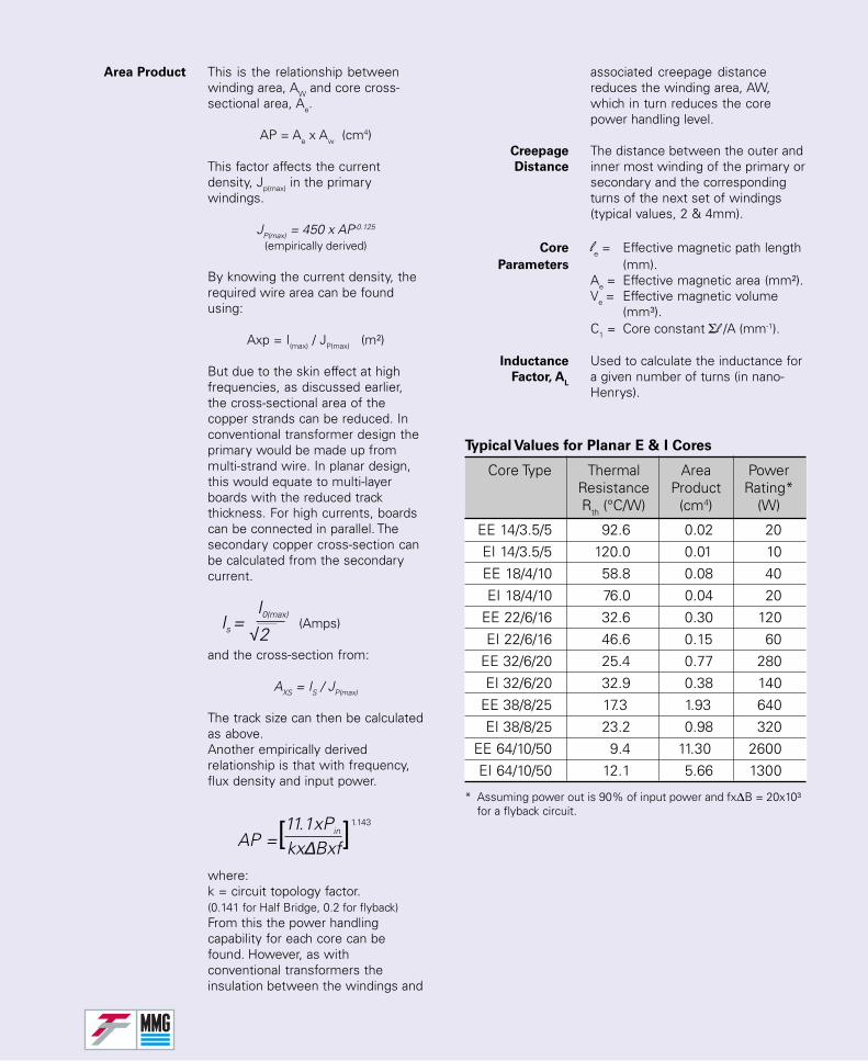
Area Product This is the relationship betweenwinding area, AW and core cross-sectional area, Ae.
AP = Ae x Aw (cm4)
This factor affects the currentdensity, Jp(max) in the primarywindings.
JP(max) = 450 x AP-0.125
(empirically derived)
By knowing the current density, therequired wire area can be foundusing:
Axp = I(max) / JP(max) (m²)
But due to the skin effect at highfrequencies, as discussed earlier,the cross-sectional area of thecopper strands can be reduced. Inconventional transformer design theprimary would be made up frommulti-strand wire. In planar design,this would equate to multi-layerboards with the reduced trackthickness. For high currents, boardscan be connected in parallel. Thesecondary copper cross-section canbe calculated from the secondarycurrent.
(Amps)
and the cross-section from:
AXS = IS / JP(max)
The track size can then be calculatedas above.Another empirically derivedrelationship is that with frequency,flux density and input power.
where:k = circuit topology factor.(0.141 for Half Bridge, 0.2 for flyback)From this the power handlingcapability for each core can befound. However, as withconventional transformers theinsulation between the windings and
associated creepage distancereduces the winding area, AW,which in turn reduces the corepower handling level.
Creepage The distance between the outer andDistance inner most winding of the primary or
secondary and the correspondingturns of the next set of windings(typical values, 2 & 4mm).
Core le = Effective magnetic path lengthParameters (mm).
Ae = Effective magnetic area (mm²).Ve = Effective magnetic volume
(mm³).C1 = Core constant Σl /A (mm-1).
Inductance Used to calculate the inductance forFactor, A
La given number of turns (in nano-Henrys).
Core Type Thermal Area PowerResistance Product Rating*Rth (°C/W) (cm4) (W)
EE 14/3.5/5 92.6 0.02 20EI 14/3.5/5 120.0 0.01 10EE 18/4/10 58.8 0.08 40EI 18/4/10 76.0 0.04 20
EE 22/6/16 32.6 0.30 120EI 22/6/16 46.6 0.15 60
EE 32/6/20 25.4 0.77 280EI 32/6/20 32.9 0.38 140
EE 38/8/25 17.3 1.93 640EI 38/8/25 23.2 0.98 320
EE 64/10/50 9.4 11.30 2600EI 64/10/50 12.1 5.66 1300
Typical Values for Planar E & I Cores
* Assuming power out is 90% of input power and fx∆B = 20x10³for a flyback circuit.
Is = √2
I0(max)
AP =[kx∆Bxf]1.14311.1xPin
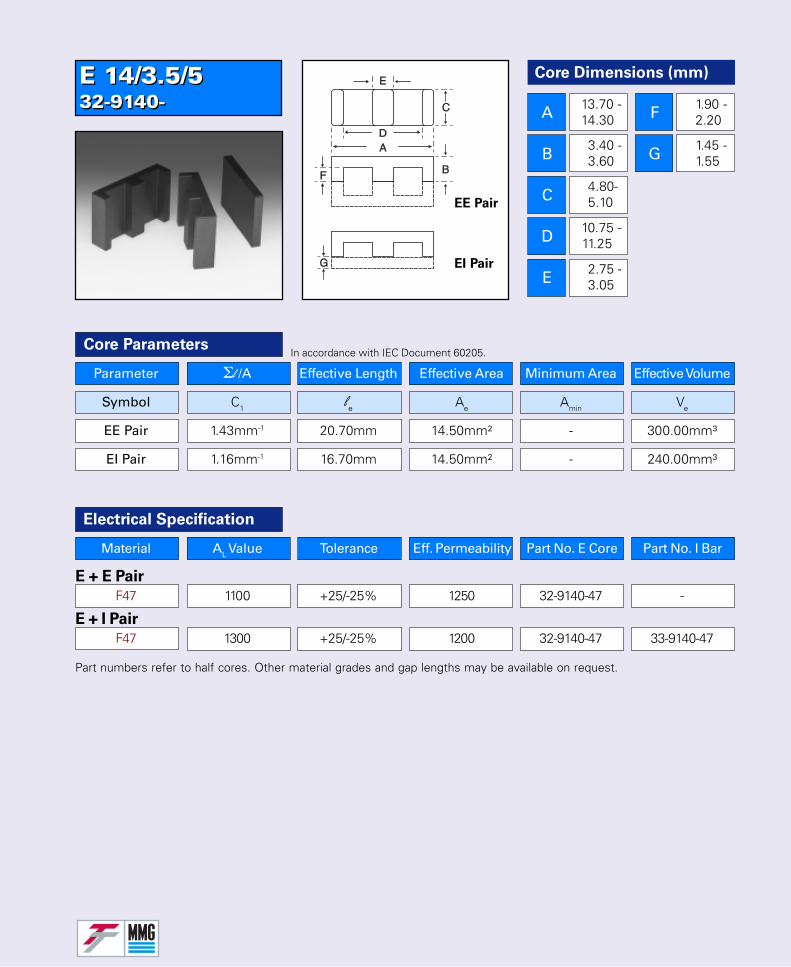
E 14/3.5/532-9140-E 14/3.5/532-9140-
Core Dimensions (mm)
A
B
C
D
E
F
G
13.70 -14.30
3.40 -3.60
4.80-5.10
10.75 -11.25
2.75 -3.05
1.90 -2.20
1.45 -1.55
Parameter Σl /A Effective Length Effective Area Minimum Area Effective Volume
Symbol C1 le Ae Amin Ve
EE Pair 1.43mm-1 20.70mm 14.50mm² - 300.00mm³
EI Pair 1.16mm-1 16.70mm 14.50mm² - 240.00mm³
Core Parameters
Material AL Value Tolerance Eff. Permeability Part No. E Core Part No. I Bar
E + E Pair
F47 1100 +25/-25% 1250 32-9140-47 -
E + I Pair
F47 1300 +25/-25% 1200 32-9140-47 33-9140-47
Electrical Specification
Part numbers refer to half cores. Other material grades and gap lengths may be available on request.
In accordance with IEC Document 60205.
EE Pair
EI Pair
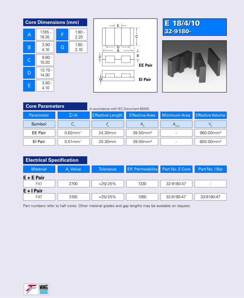
E 18/4/1032-9180-E 18/4/1032-9180-
Core Dimensions (mm)
A
B
C
D
E
F
G
17.65 -18.35
3.90 -4.10
9.80 -10.20
13.70 -14.30
3.80 -4.10
1.90 -2.20
1.90 -2.10
EE Pair
EI Pair
Parameter Σl /A Effective Length Effective Area Minimum Area Effective Volume
Symbol C1 le Ae Amin Ve
EE Pair 0.62mm-1 24.30mm 39.50mm² - 960.00mm³
EI Pair 0.51mm-1 20.30mm 39.50mm² - 800.00mm³
Core Parameters
Material AL Value Tolerance Eff. Permeability Part No. E Core Part No. I Bar
E + E Pair
F47 2700 +25/-25% 1330 32-9180-47 -
E + I Pair
F47 3100 +25/-25% 1260 32-9180-47 33-9180-47
Electrical Specification
Part numbers refer to half cores. Other material grades and gap lengths may be available on request.
In accordance with IEC Document 60205.
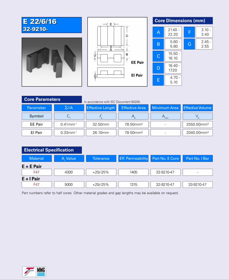
E 22/6/1632-9210-E 22/6/1632-9210-
Core Dimensions (mm)
A
B
C
D
E
F
G
21.40 -22.20
5.60 -5.80
15.50 -16.10
16.40 -17.20
4.70 -5.10
3.10 -3.40
2.45 -2.55
Parameter Σl /A Effective Length Effective Area Minimum Area Effective Volume
Symbol C1 le Ae Amin Ve
EE Pair 0.41mm-1 32.50mm 78.50mm² - 2550.00mm³
EI Pair 0.33mm-1 26.10mm 78.50mm² - 2040.00mm³
Core Parameters
Material AL Value Tolerance Eff. Permeability Part No. E Core Part No. I Bar
E + E Pair
F47 4300 +25/-25% 1405 32-9210-47 -
E + I Pair
F47 5000 +25/-25% 1315 32-9210-47 33-9210-47
Electrical Specification
Part numbers refer to half cores. Other material grades and gap lengths may be available on request.
In accordance with IEC Document 60205.
EE Pair
EI Pair
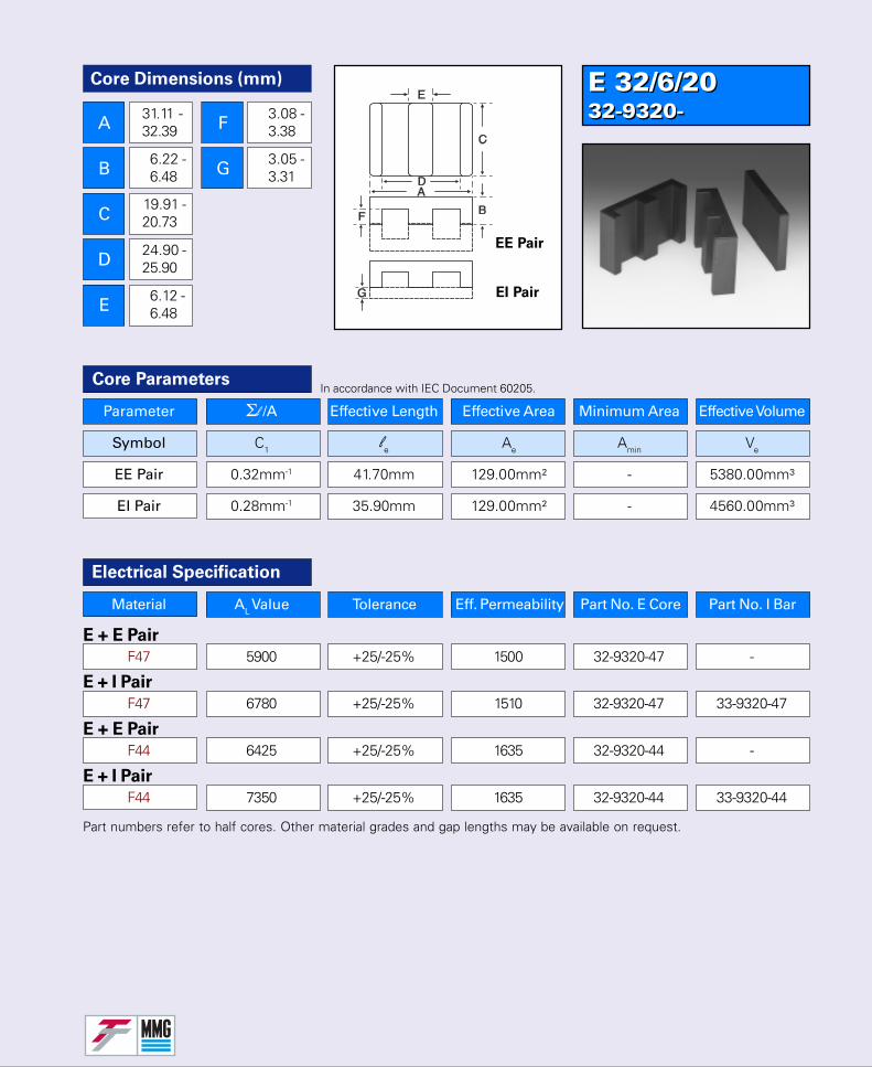
E 32/6/2032-9320-E 32/6/2032-9320-
Core Dimensions (mm)
A
B
C
D
E
F
G
31.11 -32.39
6.22 -6.48
19.91 -20.73
24.90 -25.90
6.12 -6.48
3.08 -3.38
3.05 -3.31
Parameter Σl /A Effective Length Effective Area Minimum Area Effective Volume
Symbol C1 le Ae Amin Ve
EE Pair 0.32mm-1 41.70mm 129.00mm² - 5380.00mm³
EI Pair 0.28mm-1 35.90mm 129.00mm² - 4560.00mm³
Core Parameters
Material AL Value Tolerance Eff. Permeability Part No. E Core Part No. I Bar
E + E Pair
F47 5900 +25/-25% 1500 32-9320-47 -
E + I Pair
F47 6780 +25/-25% 1510 32-9320-47 33-9320-47
E + E Pair
F44 6425 +25/-25% 1635 32-9320-44 -
E + I Pair
F44 7350 +25/-25% 1635 32-9320-44 33-9320-44
Electrical Specification
Part numbers refer to half cores. Other material grades and gap lengths may be available on request.
In accordance with IEC Document 60205.
EE Pair
EI Pair
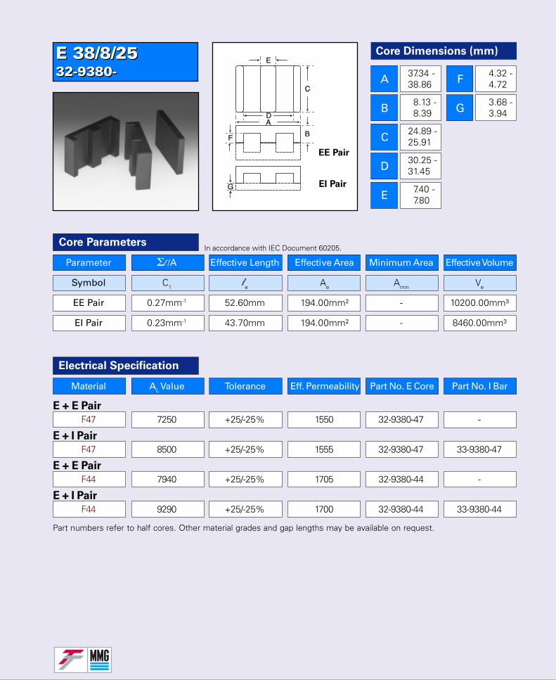
E 38/8/2532-9380-E 38/8/2532-9380-
Core Dimensions (mm)
A
B
C
D
E
F
G
37.34 -38.86
8.13 -8.39
24.89 -25.91
30.25 -31.45
7.40 -7.80
4.32 -4.72
3.68 -3.94
Parameter Σl /A Effective Length Effective Area Minimum Area Effective Volume
Symbol C1 le Ae Amin Ve
EE Pair 0.27mm-1 52.60mm 194.00mm² - 10200.00mm³
EI Pair 0.23mm-1 43.70mm 194.00mm² - 8460.00mm³
Core ParametersIn accordance with IEC Document 60205.
EE Pair
EI Pair
Material AL Value Tolerance Eff. Permeability Part No. E Core Part No. I Bar
E + E Pair
F47 7250 +25/-25% 1550 32-9380-47 -
E + I Pair
F47 8500 +25/-25% 1555 32-9380-47 33-9380-47
E + E Pair
F44 7940 +25/-25% 1705 32-9380-44 -
E + I Pair
F44 9290 +25/-25% 1700 32-9380-44 33-9380-44
Electrical Specification
Part numbers refer to half cores. Other material grades and gap lengths may be available on request.

E 64/10/5032-9640-E 64/10/5032-9640-
Core Dimensions (mm)
A
B
C
D
E
F
G
62.50 -65.10
10.07 -10.33
49.30 -51.30
52.50 -54.70
10.00 -10.40
4.97 -5.23
4.95 -5.21
Parameter Σl /A Effective Length Effective Area Minimum Area Effective Volume
Symbol C1 le Ae Amin Ve
EE Pair 0.16mm-1 79.70mm 511.00mm² - 40700.00mm³
EI Pair 0.14mm-1 69.60mm 511.00mm² - 35500.00mm³
Core Parameters
Material AL Value Tolerance Eff. Permeability Part No. E Core Part No. I Bar
E + E Pair
F47 12720 +25/-25% 1620 32-9640-47 -
E + I Pair
F47 14360 +25/-25% 1600 32-9640-47 33-9640-47
E + E Pair
F44 13300 +25/-25% 1695 32-9640-44 -
E + I Pair
F44 15050 +25/-25% 1675 32-9640-44 33-9640-44
Electrical Specification
Part numbers refer to half cores. Other material grades and gap lengths may be available on request.
In accordance with IEC Document 60205.
EE Pair
EI Pair
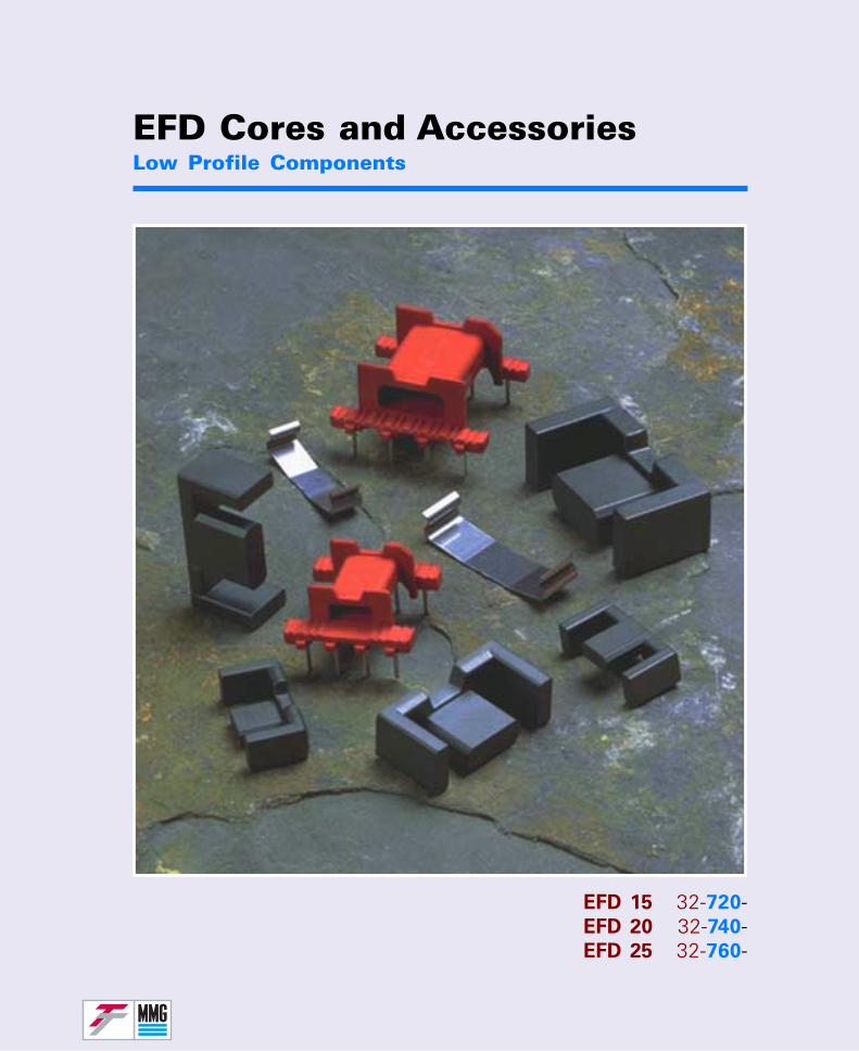
EFD Cores and AccessoriesLow Profile Components
EFD 15 32-720-EFD 20 32-740-EFD 25 32-760-
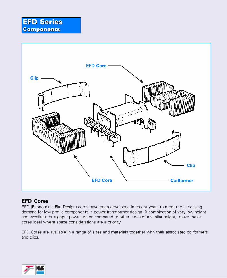
EFD SeriesComponentsEFD SeriesComponents
EFD CoresEFD (Economical Flat Design) cores have been developed in recent years to meet the increasingdemand for low profile components in power transformer design. A combination of very low heightand excellent throughput power, when compared to other cores of a similar height, make thesecores ideal where space considerations are a priority.
EFD Cores are available in a range of sizes and materials together with their associated coilformersand clips.
Clip
EFD Core Coilformer
EFD Core
Clip
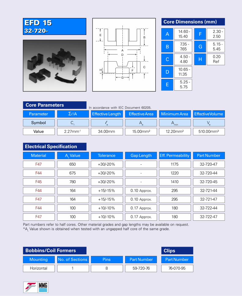
EFD 1532-720-EFD 1532-720-
Core Dimensions (mm)
A
B
C
D
E
F
G
H
14.60 -15.40
7.35 -7.65
4.50 -4.80
10.65 -11.35
5.25 -5.75
2.30 -2.50
5.15 -5.45
0.20 Ref
Parameter Σl /A Effective Length Effective Area Minimum Area Effective Volume
Symbol C1 le Ae Amin Ve
Value 2.27mm-1 34.00mm 15.00mm² 12.20mm² 510.00mm³
Core Parameters
Electrical Specification
Bobbins/Coil Formers Clips
Part Number
76-070-95
Part numbers refer to half cores. Other material grades and gap lengths may be available on request.*AL Value shown is obtained when tested with an ungapped half core of the same grade.
In accordance with IEC Document 60205.
Material AL Value Tolerance Gap Length Eff. Permeability Part Number
F47 650 +30/-20% - 1175 32-720-47
F44 675 +30/-20% - 1220 32-720-44
F45 780 +30/-20% - 1410 32-720-45
F44 164 +15/-15% 0.10 Approx. 295 32-721-44
F47 164 +15/-15% 0.10 Approx. 295 32-721-47
F44 100 +10/-10% 0.17 Approx. 180 32-722-44
F47 100 +10/-10% 0.17 Approx. 180 32-722-47
Mounting No. of Sections Pins Part Number
Horizontal 1 8 59-720-76
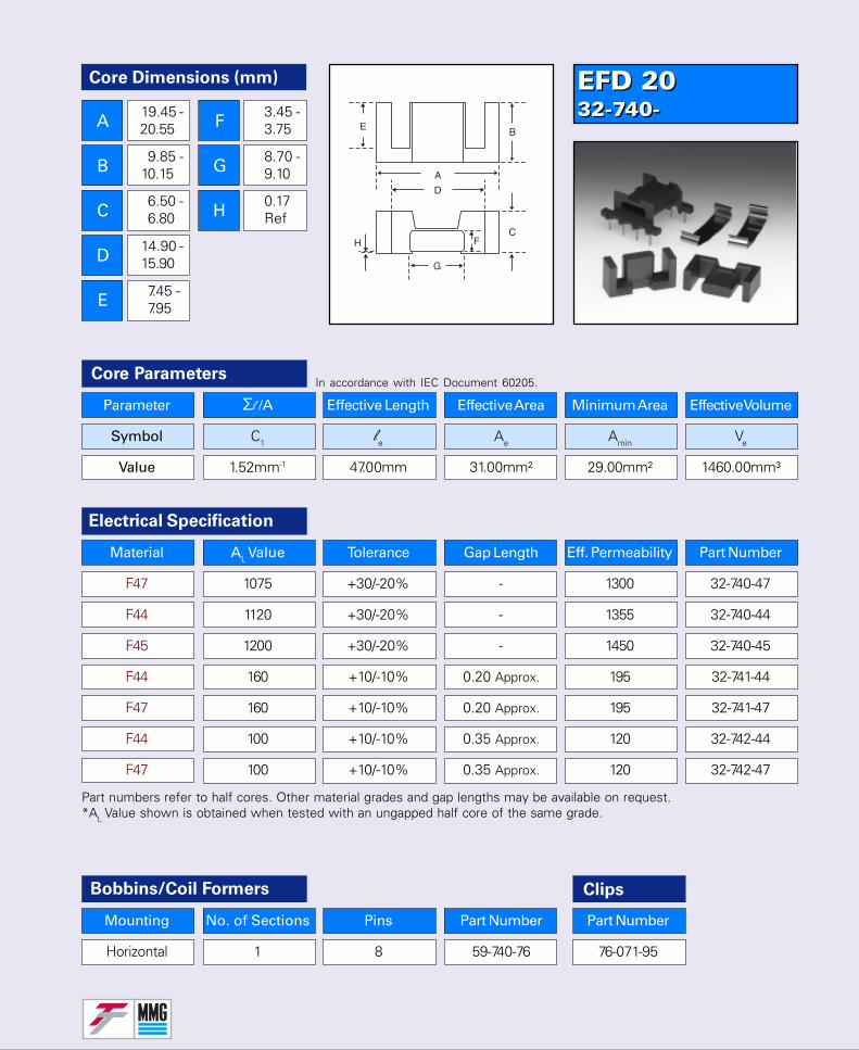
EFD 2032-740-EFD 2032-740-
Core Dimensions (mm)
A
B
C
D
E
F
G
H
19.45 -20.55
9.85 -10.15
6.50 -6.80
14.90 -15.90
7.45 -7.95
3.45 -3.75
8.70 -9.10
0.17 Ref
Parameter Σl /A Effective Length Effective Area Minimum Area Effective Volume
Symbol C1 le Ae Amin Ve
Value 1.52mm-1 47.00mm 31.00mm² 29.00mm² 1460.00mm³
Core Parameters
Electrical Specification
Bobbins/Coil Formers Clips
Part Number
76-071-95
Part numbers refer to half cores. Other material grades and gap lengths may be available on request.*AL Value shown is obtained when tested with an ungapped half core of the same grade.
In accordance with IEC Document 60205.
Material AL Value Tolerance Gap Length Eff. Permeability Part Number
F47 1075 +30/-20% - 1300 32-740-47
F44 1120 +30/-20% - 1355 32-740-44
F45 1200 +30/-20% - 1450 32-740-45
F44 160 +10/-10% 0.20 Approx. 195 32-741-44
F47 160 +10/-10% 0.20 Approx. 195 32-741-47
F44 100 +10/-10% 0.35 Approx. 120 32-742-44
F47 100 +10/-10% 0.35 Approx. 120 32-742-47
Mounting No. of Sections Pins Part Number
Horizontal 1 8 59-740-76
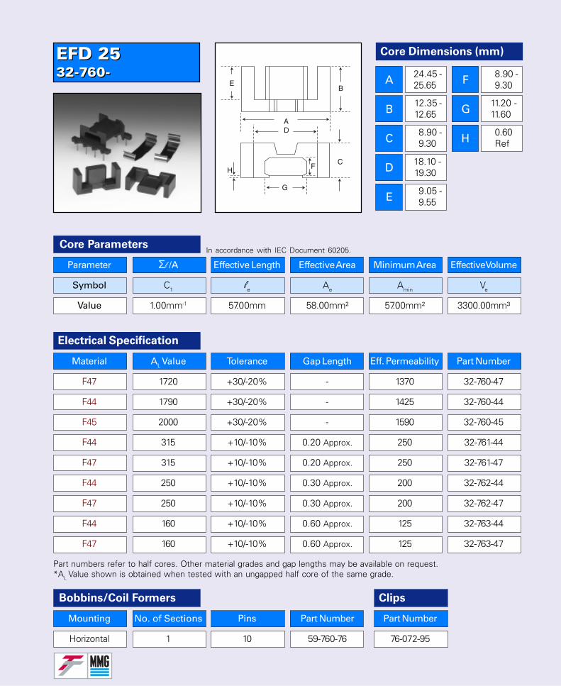
EFD 2532-760-EFD 2532-760-
Core Dimensions (mm)
A
B
C
D
E
F
G
H
24.45 -25.65
12.35 -12.65
8.90 -9.30
18.10 -19.30
9.05 -9.55
8.90 -9.30
11.20 -11.60
0.60 Ref
Parameter Σl /A Effective Length Effective Area Minimum Area Effective Volume
Symbol C1 le Ae Amin Ve
Value 1.00mm-1 57.00mm 58.00mm² 57.00mm² 3300.00mm³
Core Parameters
Electrical Specification
Bobbins/Coil Formers Clips
Part Number
76-072-95
Part numbers refer to half cores. Other material grades and gap lengths may be available on request.*AL Value shown is obtained when tested with an ungapped half core of the same grade.
In accordance with IEC Document 60205.
Material AL Value Tolerance Gap Length Eff. Permeability Part Number
F47 1720 +30/-20% - 1370 32-760-47
F44 1790 +30/-20% - 1425 32-760-44
F45 2000 +30/-20% - 1590 32-760-45
F44 315 +10/-10% 0.20 Approx. 250 32-761-44
F47 315 +10/-10% 0.20 Approx. 250 32-761-47
F44 250 +10/-10% 0.30 Approx. 200 32-762-44
F47 250 +10/-10% 0.30 Approx. 200 32-762-47
F44 160 +10/-10% 0.60 Approx. 125 32-763-44
F47 160 +10/-10% 0.60 Approx. 125 32-763-47
Mounting No. of Sections Pins Part Number
Horizontal 1 10 59-760-76
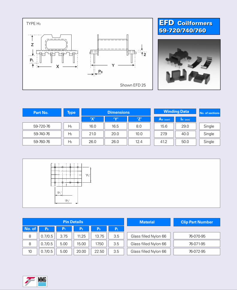
EFD Coilformers59-720/740/760EFD Coilformers59-720/740/760
No. of sectionsPart No. Type Dimensions
‘X’ ‘Y’ ‘Z’
Winding Data
AN (mm²) IN (mm)
Material
No. of
Clip Part Number
P1 P2 P3 PL
Pin Details
P0
TYPE H3
Shown EFD 25
‘P2‘
‘P1’
‘P3’
59-720-76 H3 16.0 16.5 8.0 15.6 29.0 Single
59-740-76 H3 21.0 20.0 10.0 27.9 40.0 Single
59-760-76 H3 26.0 26.0 12.4 41.2 50.0 Single
8 0.7/0.5 3.75 11.25 13.75 3.5 Glass filled Nylon 66 76-070-95
8 0.7/0.5 5.00 15.00 17.50 3.5 Glass filled Nylon 66 76-071-95
10 0.7/0.5 5.00 20.00 22.50 3.5 Glass filled Nylon 66 76-072-95
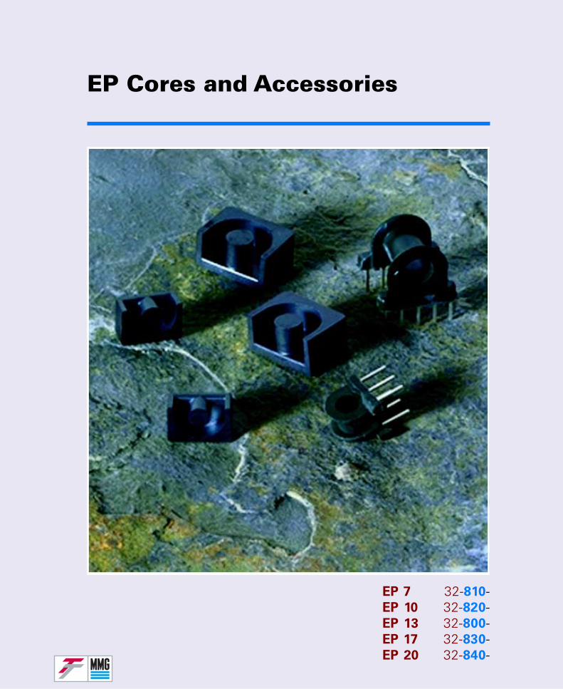
EP Cores and Accessories
EP 7 32-810-EP 10 32-820-EP 13 32-800-EP 17 32-830-EP 20 32-840-
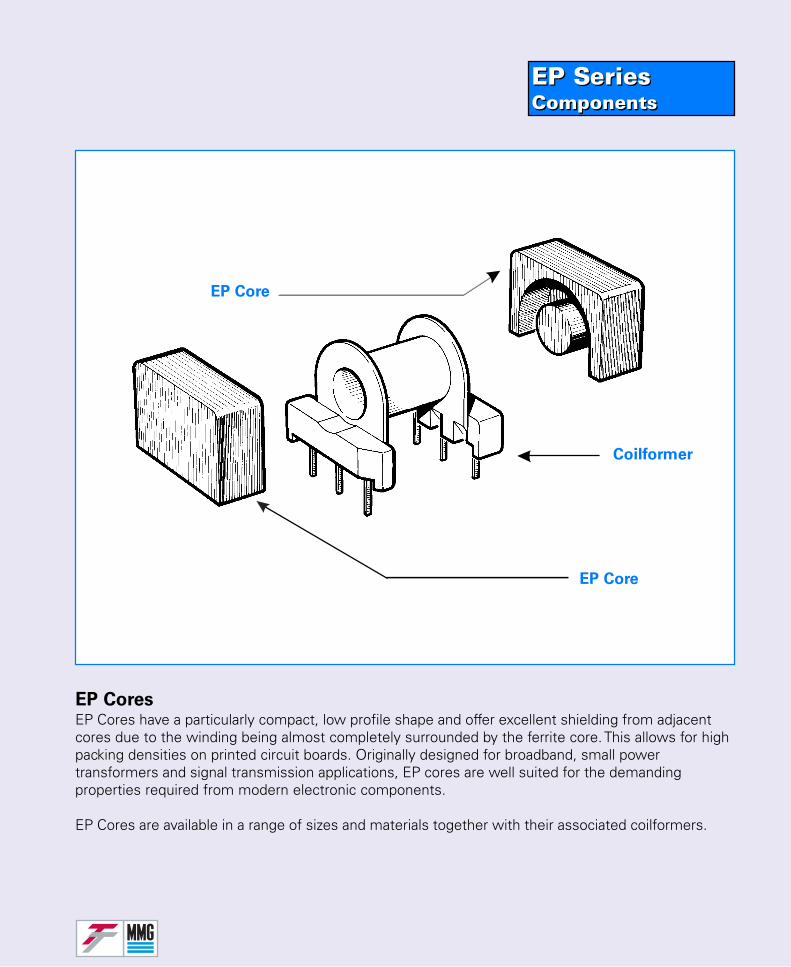
EP SeriesComponentsEP SeriesComponents
EP CoresEP Cores have a particularly compact, low profile shape and offer excellent shielding from adjacentcores due to the winding being almost completely surrounded by the ferrite core. This allows for highpacking densities on printed circuit boards. Originally designed for broadband, small powertransformers and signal transmission applications, EP cores are well suited for the demandingproperties required from modern electronic components.
EP Cores are available in a range of sizes and materials together with their associated coilformers.
EP Core
EP Core
Coilformer
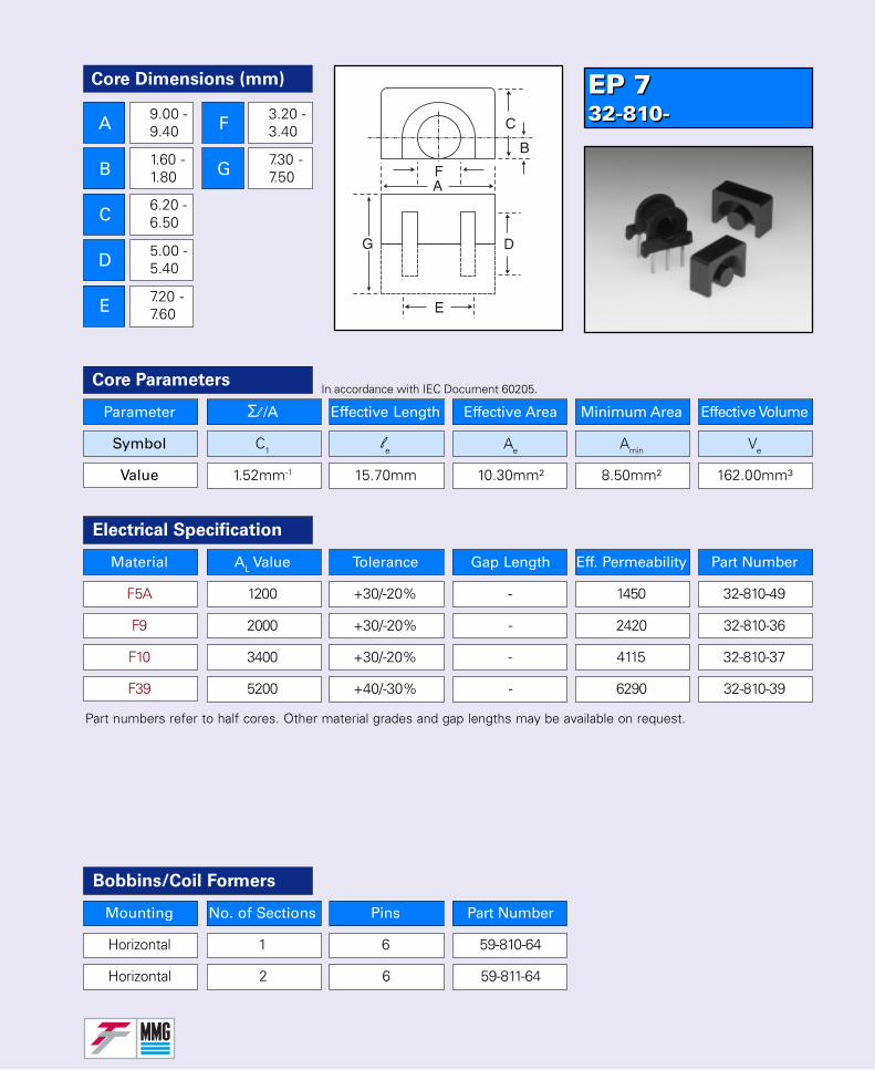
Core Dimensions (mm)
A
B
C
D
E
F
G
9.00 -9.40
1.60 -1.80
6.20 -6.50
5.00 -5.40
7.20 -7.60
3.20 -3.40
7.30 -7.50
Parameter Σl /A Effective Length Effective Area Minimum Area Effective Volume
Symbol C1 le Ae Amin Ve
Value 1.52mm-1 15.70mm 10.30mm² 8.50mm² 162.00mm³
Core Parameters
Material AL Value Tolerance Gap Length Eff. Permeability Part Number
F5A 1200 +30/-20% - 1450 32-810-49
F9 2000 +30/-20% - 2420 32-810-36
F10 3400 +30/-20% - 4115 32-810-37
F39 5200 +40/-30% - 6290 32-810-39
Electrical Specification
Bobbins/Coil Formers
Mounting No. of Sections Pins Part Number
Horizontal 1 6 59-810-64
Horizontal 2 6 59-811-64
Part numbers refer to half cores. Other material grades and gap lengths may be available on request.
In accordance with IEC Document 60205.
EP 732-810-EP 732-810-
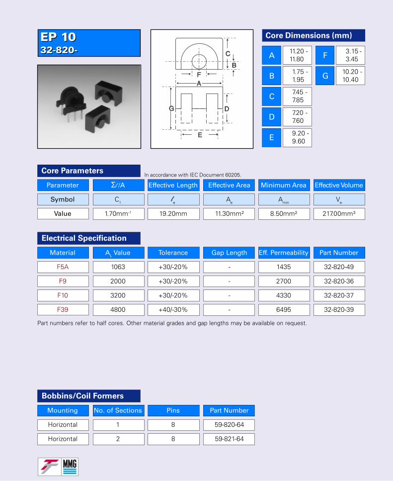
Parameter Σl /A Effective Length Effective Area Minimum Area Effective Volume
Symbol C1 le Ae Amin Ve
Value 1.70mm-1 19.20mm 11.30mm² 8.50mm² 217.00mm³
Core Parameters
Material AL Value Tolerance Gap Length Eff. Permeability Part Number
F5A 1063 +30/-20% - 1435 32-820-49
F9 2000 +30/-20% - 2700 32-820-36
F10 3200 +30/-20% - 4330 32-820-37
F39 4800 +40/-30% - 6495 32-820-39
Electrical Specification
Part numbers refer to half cores. Other material grades and gap lengths may be available on request.
In accordance with IEC Document 60205.
Bobbins/Coil Formers
Mounting No. of Sections Pins Part Number
Horizontal 1 8 59-820-64
Horizontal 2 8 59-821-64
Core Dimensions (mm)
A
B
C
D
E
F
G
11.20 -11.80
1.75 -1.95
7.45 -7.85
7.20 -7.60
9.20 -9.60
3.15 -3.45
10.20 -10.40
EP 1032-820-EP 1032-820-
Core Dimensions (mm)
A
B
C
D
E
F
G
12.20 -12.80
2.30 -2.50
8.60 -9.00
9.00 -9.40
9.70 -10.30
4.20 -4.50
12.70 -13.00
Parameter Σl /A Effective Length Effective Area Minimum Area Effective Volume
Symbol C1 le Ae Amin Ve
Value 1.24mm-1 24.20mm 19.50mm² 14.90mm² 472.00mm³
Core Parameters
Material AL Value Tolerance Gap Length Eff. Permeability Part Number
F44 1235 +30/-20% - 1220 32-800-44
F9 2800 +30/-20% - 2760 32-800-36
F10 4400 +30/-20% - 4340 32-800-37
F39 7000 +40/-30% - 6905 32-800-39
Electrical Specification
Bobbins/Coil Formers
Mounting No. of Sections Pins Part Number
Horizontal 1 10 59-805-64
Horizontal 2 10 59-806-64
Part numbers refer to half cores. Other material grades and gap lengths may be available on request.
In accordance with IEC Document 60205.
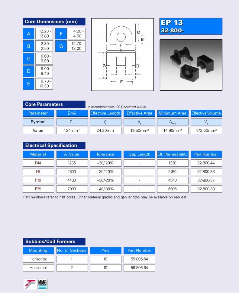
EP 1332-800-EP 1332-800-
Parameter Σl /A Effective Length Effective Area Minimum Area Effective Volume
Symbol C1 le Ae Amin Ve
Value 0.84mm-1 28.50mm 33.90mm² 25.50mm² 966.00mm³
Core Parameters
Material AL Value Tolerance Gap Length Eff. Permeability Part Number
F44 2130 +30/-20% - 1425 32-830-44
F9 4310 +30/-20% - 2880 32-830-36
F10 6875 +30/-20% - 4595 32-830-37
F39 11400 +40/-30% - 7620 32-830-39
Electrical Specification
Part numbers refer to half cores. Other material grades and gap lengths may be available on request.
In accordance with IEC Document 60205.
Bobbins/Coil Formers
Mounting No. of Sections Pins Part Number
Horizontal 1 8 59-830-64
Horizontal 2 8 59-831-64
Core Dimensions (mm)
A
B
C
D
E
F
G
17.50 -18.50
3.05 -3.45
10.75 -11.25
11.20 -11.80
11.50 -12.50
5.50 -5.85
16.60 -17.00
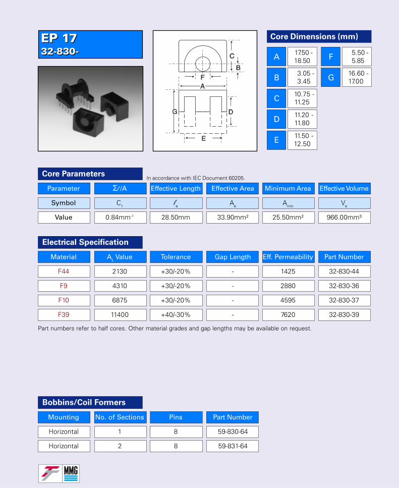
EP 1732-830-EP 1732-830-
Core Dimensions (mm)
A
B
C
D
E
F
G
23.50 -24.50
4.30 -4.70
14.60 -15.30
14.00 -14.60
16.10 -16.90
8.50 -9.00
21.20 -21.60
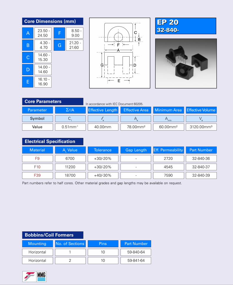
Parameter Σl /A Effective Length Effective Area Minimum Area Effective Volume
Symbol C1 le Ae Amin Ve
Value 0.51mm-1 40.00mm 78.00mm² 60.00mm² 3120.00mm³
Core Parameters
Material AL Value Tolerance Gap Length Eff. Permeability Part Number
F9 6700 +30/-20% - 2720 32-840-36
F10 11200 +30/-20% - 4545 32-840-37
F39 18700 +40/-30% - 7590 32-840-39
Electrical Specification
Part numbers refer to half cores. Other material grades and gap lengths may be available on request.
In accordance with IEC Document 60205.
Bobbins/Coil Formers
Mounting No. of Sections Pins Part Number
Horizontal 1 10 59-840-64
Horizontal 2 10 59-841-64
EP 2032-840-EP 2032-840-
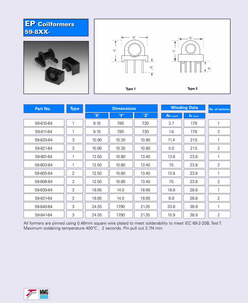
EP Coilformers59-8XX-EP Coilformers59-8XX-
No. of sectionsPart No. Type Dimensions
‘X’ ‘Y’ ‘Z’
Winding Data
AN (mm²) IN (mm)
Type 1 Type 2
‘Y’
‘X’
‘PL’
‘X’
‘PL’
‘Y’
All formers are pinned using 0.46mm square wire plated to meet solderability to meet IEC 68-2-20B, Test T.Maximum soldering temperature 400°C , 2 seconds. Pin pull out 2.7N min.
59-810-64 1 9.10 7.85 7.30 3.7 17.9 1
59-811-64 1 9.10 7.85 7.30 1.6 17.9 2
59-820-64 3 10.90 10.30 10.90 11.4 21.5 1
59-821-64 3 10.90 10.30 10.90 5.0 21.5 2
59-801-64 1 12.50 10.80 13.40 13.8 23.8 1
59-803-64 1 12.50 10.80 13.40 7.5 23.8 2
59-805-64 2 12.50 10.80 13.40 13.8 23.8 1
59-806-64 2 12.50 10.80 13.40 7.5 23.8 2
59-830-64 3 18.85 14.0 18.85 18.8 28.8 1
59-831-64 3 18.85 14.0 18.85 8.9 28.8 2
59-840-64 3 24.55 17.90 21.35 33.8 38.9 1
59-841-64 3 24.55 17.90 21.35 15.9 38.9 2
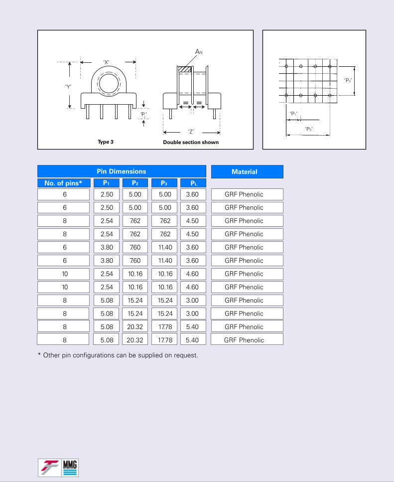
* Other pin configurations can be supplied on request.
‘P2‘
‘P1’
‘P3’
Material
No. of pins* P1 P2 P3 PL
Pin Dimensions
‘X’
‘Y’
‘Z’
Type 3
‘PL’
‘P2‘
‘P1’
‘P3’
AN
Double section shown
6 2.50 5.00 5.00 3.60 GRF Phenolic
6 2.50 5.00 5.00 3.60 GRF Phenolic
8 2.54 7.62 7.62 4.50 GRF Phenolic
8 2.54 7.62 7.62 4.50 GRF Phenolic
6 3.80 7.60 11.40 3.60 GRF Phenolic
6 3.80 7.60 11.40 3.60 GRF Phenolic
10 2.54 10.16 10.16 4.60 GRF Phenolic
10 2.54 10.16 10.16 4.60 GRF Phenolic
8 5.08 15.24 15.24 3.00 GRF Phenolic
8 5.08 15.24 15.24 3.00 GRF Phenolic
8 5.08 20.32 17.78 5.40 GRF Phenolic
8 5.08 20.32 17.78 5.40 GRF Phenolic
1234512345
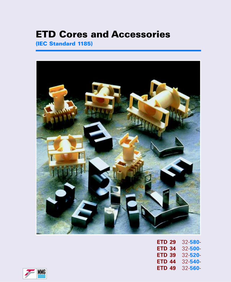
ETD Cores and Accessories(IEC Standard 1185)
ETD 29 32-580-ETD 34 32-500-ETD 39 32-520-ETD 44 32-540-ETD 49 32-560-
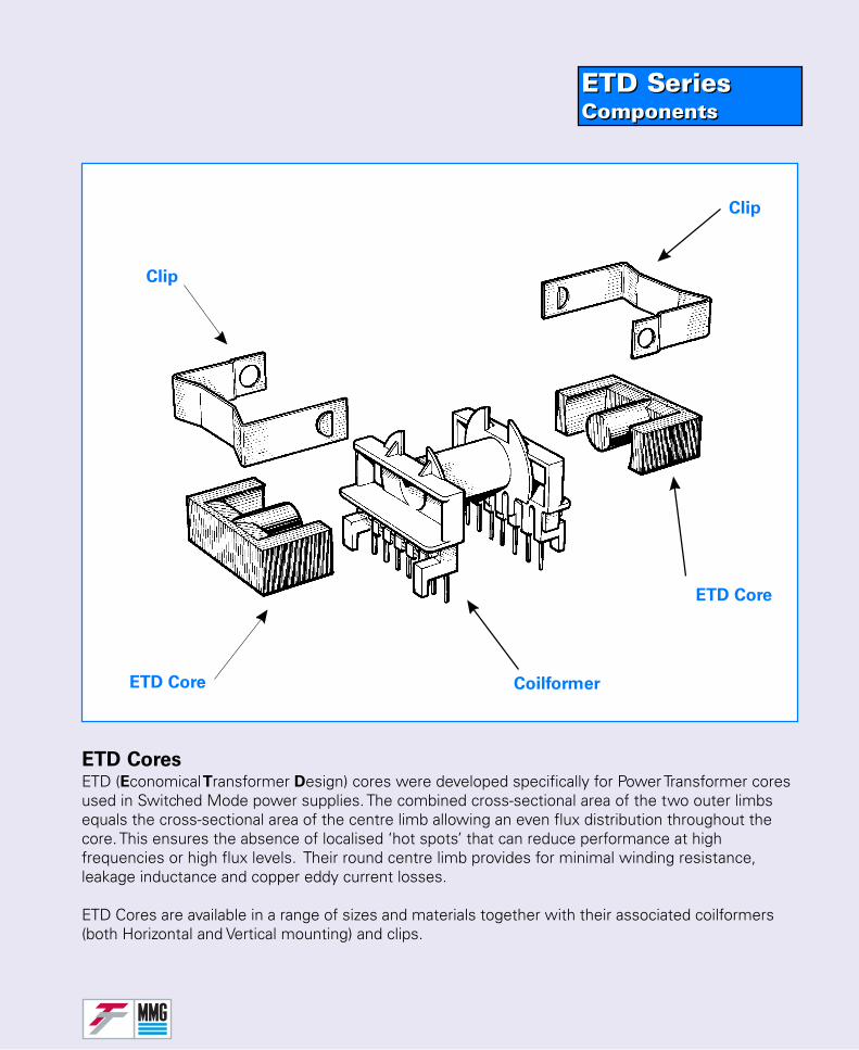
ETD SeriesComponentsETD SeriesComponents
ETD CoresETD (Economical Transformer Design) cores were developed specifically for Power Transformer coresused in Switched Mode power supplies. The combined cross-sectional area of the two outer limbsequals the cross-sectional area of the centre limb allowing an even flux distribution throughout thecore. This ensures the absence of localised ‘hot spots’ that can reduce performance at highfrequencies or high flux levels. Their round centre limb provides for minimal winding resistance,leakage inductance and copper eddy current losses.
ETD Cores are available in a range of sizes and materials together with their associated coilformers(both Horizontal and Vertical mounting) and clips.
Clip
ETD Core
CoilformerETD Core
Clip
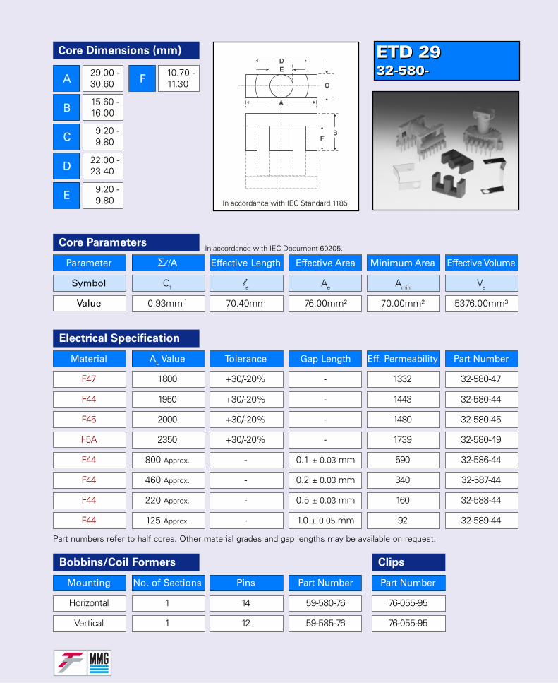
ETD 2932-580-ETD 2932-580-
Parameter Σl /A Effective Length Effective Area Minimum Area Effective Volume
Symbol C1 le Ae Amin Ve
Value 0.93mm-1 70.40mm 76.00mm² 70.00mm² 5376.00mm³
Core Parameters
Material AL Value Tolerance Gap Length Eff. Permeability Part Number
F47 1800 +30/-20% - 1332 32-580-47
F44 1950 +30/-20% - 1443 32-580-44
F45 2000 +30/-20% - 1480 32-580-45
F5A 2350 +30/-20% - 1739 32-580-49
F44 800 Approx. - 0.1 ± 0.03 mm 590 32-586-44
F44 460 Approx. - 0.2 ± 0.03 mm 340 32-587-44
F44 220 Approx. - 0.5 ± 0.03 mm 160 32-588-44
F44 125 Approx. - 1.0 ± 0.05 mm 92 32-589-44
Electrical Specification
Bobbins/Coil Formers
Mounting No. of Sections Pins Part Number
Horizontal 1 14 59-580-76
Vertical 1 12 59-585-76
Clips
Part Number
76-055-95
76-055-95
Part numbers refer to half cores. Other material grades and gap lengths may be available on request.
In accordance with IEC Standard 1185
In accordance with IEC Document 60205.
Core Dimensions (mm)
A
B
C
D
E
F29.00 -30.60
15.60 -16.00
9.20 -9.80
22.00 -23.40
9.20 -9.80
10.70 -11.30
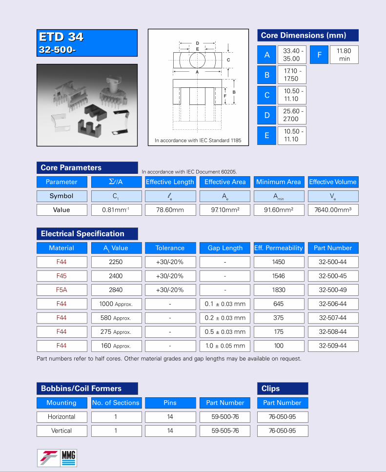
ETD 3432-500-ETD 3432-500-
Parameter Σl /A Effective Length Effective Area Minimum Area Effective Volume
Symbol C1 le Ae Amin Ve
Value 0.81mm-1 78.60mm 97.10mm² 91.60mm² 7640.00mm³
Core Parameters
Material AL Value Tolerance Gap Length Eff. Permeability Part Number
F44 2250 +30/-20% - 1450 32-500-44
F45 2400 +30/-20% - 1546 32-500-45
F5A 2840 +30/-20% - 1830 32-500-49
F44 1000 Approx. - 0.1 ± 0.03 mm 645 32-506-44
F44 580 Approx. - 0.2 ± 0.03 mm 375 32-507-44
F44 275 Approx. - 0.5 ± 0.03 mm 175 32-508-44
F44 160 Approx. - 1.0 ± 0.05 mm 100 32-509-44
Electrical Specification
Bobbins/Coil Formers
Mounting No. of Sections Pins Part Number
Horizontal 1 14 59-500-76
Vertical 1 14 59-505-76
Clips
Part Number
76-050-95
76-050-95
Part numbers refer to half cores. Other material grades and gap lengths may be available on request.
In accordance with IEC Standard 1185
In accordance with IEC Document 60205.
Core Dimensions (mm)
A
B
C
D
E
F33.40 -35.00
17.10 -17.50
10.50 -11.10
25.60 -27.00
10.50 -11.10
11.80 min
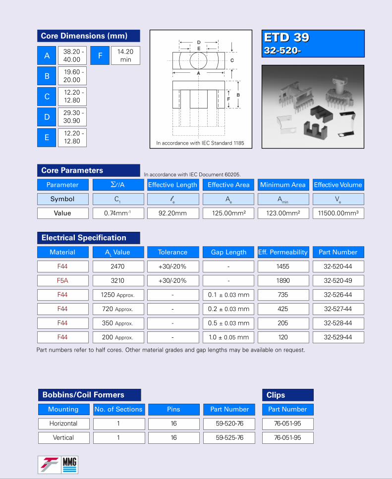
ETD 3932-520-ETD 3932-520-
Parameter Σl /A Effective Length Effective Area Minimum Area Effective Volume
Symbol C1 le Ae Amin Ve
Value 0.74mm-1 92.20mm 125.00mm² 123.00mm² 11500.00mm³
Core Parameters
Material AL Value Tolerance Gap Length Eff. Permeability Part Number
F44 2470 +30/-20% - 1455 32-520-44
F5A 3210 +30/-20% - 1890 32-520-49
F44 1250 Approx. - 0.1 ± 0.03 mm 735 32-526-44
F44 720 Approx. - 0.2 ± 0.03 mm 425 32-527-44
F44 350 Approx. - 0.5 ± 0.03 mm 205 32-528-44
F44 200 Approx. - 1.0 ± 0.05 mm 120 32-529-44
Electrical Specification
Bobbins/Coil Formers
Mounting No. of Sections Pins Part Number
Horizontal 1 16 59-520-76
Vertical 1 16 59-525-76
Clips
Part Number
76-051-95
76-051-95
Part numbers refer to half cores. Other material grades and gap lengths may be available on request.
In accordance with IEC Document 60205.
In accordance with IEC Standard 1185
Core Dimensions (mm)
A
B
C
D
E
F38.20 -40.00
19.60 -20.00
12.20 -12.80
29.30 -30.90
12.20 -12.80
14.20 min
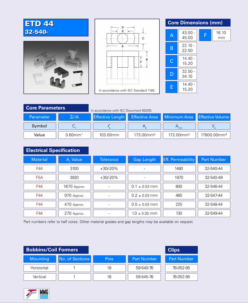
ETD 4432-540-ETD 4432-540-
In accordance with IEC Standard 1185
Parameter Σl /A Effective Length Effective Area Minimum Area Effective Volume
Symbol C1 le Ae Amin Ve
Value 0.60mm-1 103.00mm 173.00mm² 172.00mm² 17800.00mm³
Core Parameters
Material AL Value Tolerance Gap Length Eff. Permeability Part Number
F44 3100 +30/-20% - 1480 32-540-44
F5A 3920 +30/-20% - 1870 32-540-49
F44 1670 Approx. - 0.1 ± 0.03 mm 800 32-546-44
F44 970 Approx. - 0.2 ± 0.03 mm 460 32-547-44
F44 470 Approx. - 0.5 ± 0.03 mm 225 32-548-44
F44 270 Approx. - 1.0 ± 0.05 mm 130 32-549-44
Electrical Specification
Bobbins/Coil Formers
Mounting No. of Sections Pins Part Number
Horizontal 1 18 59-540-76
Vertical 1 18 59-545-76
Clips
Part Number
76-052-95
76-052-95
Part numbers refer to half cores. Other material grades and gap lengths may be available on request.
In accordance with IEC Document 60205.
Core Dimensions (mm)
A
B
C
D
E
F43.00 -45.00
22.10 -22.50
14.40 -15.20
32.50 -34.10
14.40 -15.20
16.10 min

ETD 4932-560-ETD 4932-560-
Parameter Σl /A Effective Length Effective Area Minimum Area Effective Volume
Symbol C1 le Ae Amin Ve
Value 0.54mm-1 114.00mm 211.00mm² 209.00mm² 24000.00mm³
Core Parameters
Material AL Value Tolerance Gap Length Eff. Permeability Part Number
F44 3525 +30/-20% - 1515 32-560-44
F5A 4400 +30/-20% - 1890 32-560-49
F44 2000 Approx. - 0.1 ± 0.03 mm 860 32-566-44
F44 1165 Approx. - 0.2 ± 0.03 mm 500 32-567-44
F44 570 Approx. - 0.5 ± 0.03 mm 245 32-568-44
F44 335 Approx. - 1.0 ± 0.05 mm 145 32-569-44
Electrical Specification
Clips
Part numbers refer to half cores. Other material grades and gap lengths may be available on request.
In accordance with IEC Document 60205.
In accordance with IEC Standard 1185
Bobbins/Coil Formers
Mounting No. of Sections Pins Part Number
Horizontal 1 20 59-560-76
Vertical 1 20 59-565-76
Part Number
76-053-95
76-053-95
Clips
Core Dimensions (mm)
A
B
C
D
E
F47.60 -49.80
24.50 -24.90
15.90 -16.70
36.10 -37.90
15.90 -16.70
17.70 min
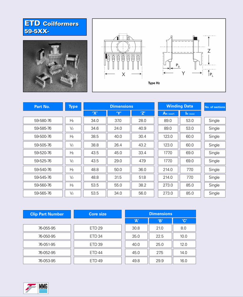
ETD Coilformers59-5XX-ETD Coilformers59-5XX-
No. of sectionsPart No. Type Dimensions
‘X’ ‘Y’ ‘Z’
Winding Data
AN (mm²) IN (mm)
Clip Part Number Core size
‘A’ ‘B’ ‘C’
Dimensions
Type H2
59-580-76 H2 34.0 37.0 28.0 89.0 53.0 Single
59-585-76 V2 34.6 24.0 40.9 89.0 53.0 Single
59-500-76 H2 38.5 40.0 30.4 123.0 60.0 Single
59-505-76 V2 38.8 26.4 43.2 123.0 60.0 Single
59-520-76 H2 43.5 45.0 33.4 177.0 69.0 Single
59-525-76 V2 43.5 29.0 47.9 177.0 69.0 Single
59-540-76 H2 48.8 50.0 36.0 214.0 77.0 Single
59-545-76 V2 48.8 31.5 51.8 214.0 77.0 Single
59-560-76 H2 53.5 55.0 38.2 273.0 85.0 Single
59-565-76 V2 53.5 34.0 56.0 273.0 85.0 Single
76-055-95 ETD 29 30.8 21.0 8.0
76-050-95 ETD 34 35.0 22.5 10.0
76-051-95 ETD 39 40.0 25.0 12.0
76-052-95 ETD 44 45.0 27.5 14.0
76-053-95 ETD 49 49.8 29.9 16.0
P0
PL
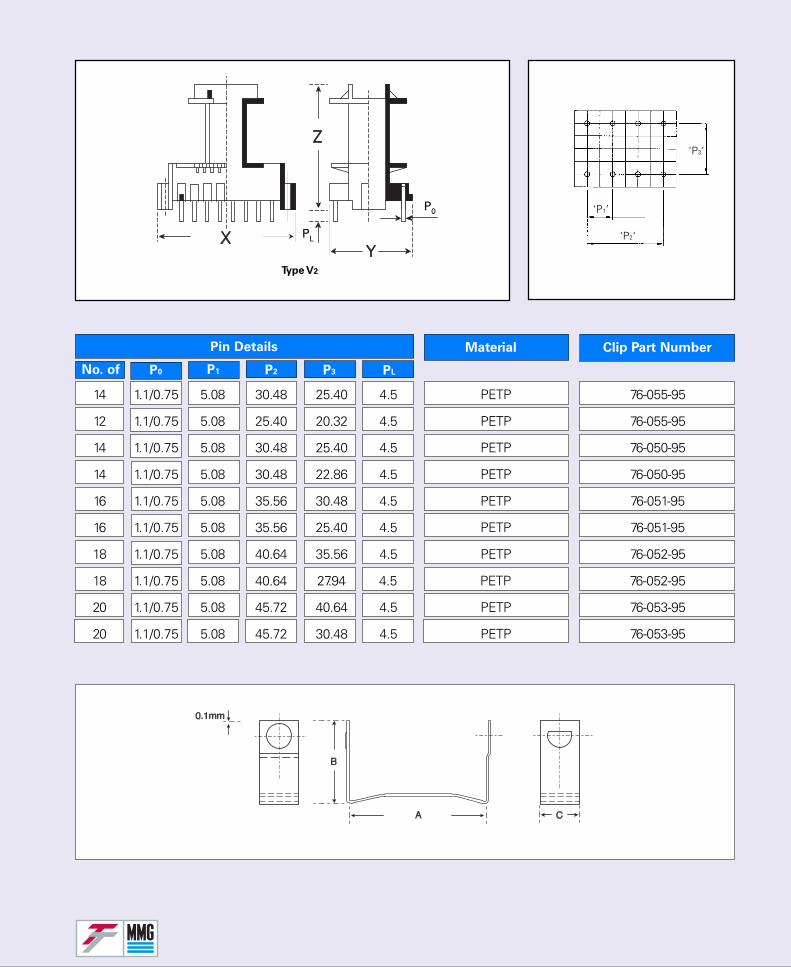
Material
No. of
Clip Part Number
P1 P2 P3 PL
Pin Details
P0
Type V2
‘P2‘
‘P1’
‘P3’
14 1.1/0.75 5.08 30.48 25.40 4.5 PETP 76-055-95
12 1.1/0.75 5.08 25.40 20.32 4.5 PETP 76-055-95
14 1.1/0.75 5.08 30.48 25.40 4.5 PETP 76-050-95
14 1.1/0.75 5.08 30.48 22.86 4.5 PETP 76-050-95
16 1.1/0.75 5.08 35.56 30.48 4.5 PETP 76-051-95
16 1.1/0.75 5.08 35.56 25.40 4.5 PETP 76-051-95
18 1.1/0.75 5.08 40.64 35.56 4.5 PETP 76-052-95
18 1.1/0.75 5.08 40.64 27.94 4.5 PETP 76-052-95
20 1.1/0.75 5.08 45.72 40.64 4.5 PETP 76-053-95
20 1.1/0.75 5.08 45.72 30.48 4.5 PETP 76-053-95
P0
PL
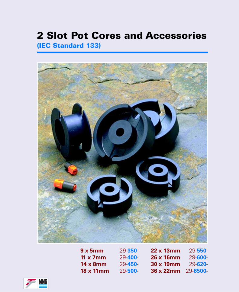
2 Slot Pot Cores and Accessories(IEC Standard 133)
22 x 13mm 29-550-26 x 16mm 29-600-30 x 19mm 29-620-36 x 22mm 29-6500-
9 x 5mm 29-350-11 x 7mm 29-400-14 x 8mm 29-450-18 x 11mm 29-500-
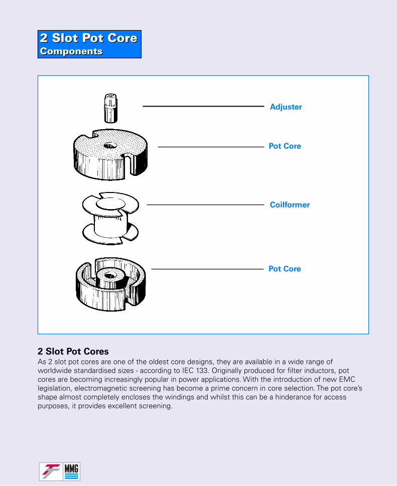
2 Slot Pot CoreComponents2 Slot Pot CoreComponents
2 Slot Pot CoresAs 2 slot pot cores are one of the oldest core designs, they are available in a wide range ofworldwide standardised sizes - according to IEC 133. Originally produced for filter inductors, potcores are becoming increasingly popular in power applications. With the introduction of new EMClegislation, electromagnetic screening has become a prime concern in core selection. The pot core’sshape almost completely encloses the windings and whilst this can be a hinderance for accesspurposes, it provides excellent screening.
Pot Core
Coilformer
Pot Core
Adjuster
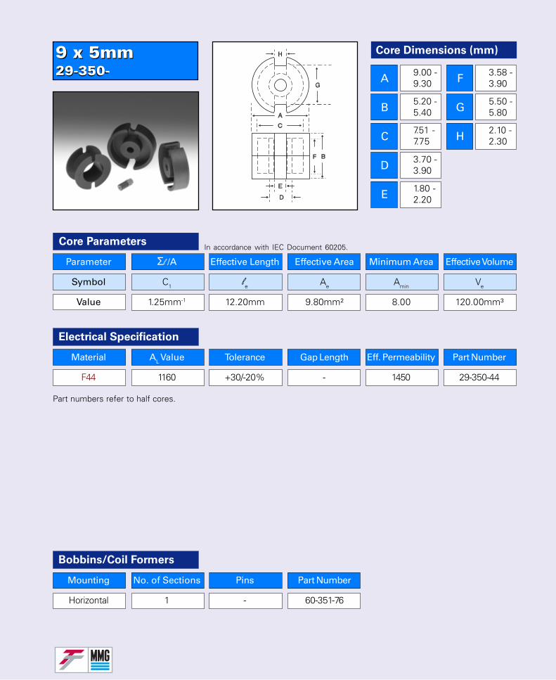
9 x 5mm29-350-9 x 5mm29-350-
Core Dimensions (mm)
A
B
C
D
E
F
G
H
9.00 -9.30
5.20 -5.40
7.51 -7.75
3.70 -3.90
1.80 -2.20
3.58 -3.90
5.50 -5.80
2.10 -2.30
Parameter Σl /A Effective Length Effective Area Minimum Area Effective Volume
Symbol C1 le Ae Amin Ve
Value 1.25mm-1 12.20mm 9.80mm² 8.00 120.00mm³
Core Parameters
Electrical Specification
Part numbers refer to half cores.
In accordance with IEC Document 60205.
Bobbins/Coil Formers
Mounting No. of Sections Pins Part Number
Horizontal 1 - 60-351-76
Material AL Value Tolerance Gap Length Eff. Permeability Part Number
F44 1160 +30/-20% - 1450 29-350-44
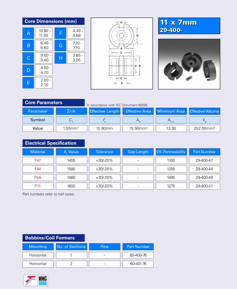
11 x 7mm29-400-11 x 7mm29-400-
Parameter Σl /A Effective Length Effective Area Minimum Area Effective Volume
Symbol C1 le Ae Amin Ve
Value 1.00mm-1 15.90mm 15.90mm² 13.30 252.00mm³
Core Parameters
Material AL Value Tolerance Gap Length Eff. Permeability Part Number
F47 1455 +30/-20% - 1160 29-400-47
F44 1580 +30/-20% - 1255 29-400-44
F5A 1880 +30/-20% - 1495 29-400-49
P11 1600 +30/-20% - 1275 29-400-41
Electrical Specification
Part numbers refer to half cores.
In accordance with IEC Document 60205.
Bobbins/Coil Formers
Core Dimensions (mm)
A
B
C
D
E
F
G
H
10.90 -11.30
6.40 -6.60
9.00 -9.40
4.50 -4.70
2.00 -2.10
4.40 -4.68
7.20 -7.70
2.65 -3.05
Mounting No. of Sections Pins Part Number
Horizontal 1 - 60-400-76
Horizontal 2 - 60-401-76
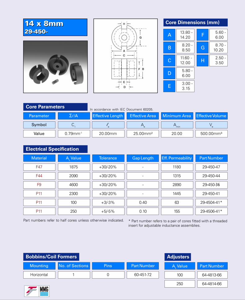
14 x 8mm29-450-14 x 8mm29-450-
Core Dimensions (mm)
A
B
C
D
E
F
G
H
13.80 -14.20
8.20 -8.50
11.60 -12.00
5.80 -6.00
3.00 -3.15
5.60 -6.00
8.70 -10.20
2.50 -3.50
Parameter Σl /A Effective Length Effective Area Minimum Area Effective Volume
Symbol C1 le Ae Amin Ve
Value 0.79mm-1 20.00mm 25.00mm² 20.00 500.00mm³
Core Parameters
Bobbins/Coil Formers
Mounting No. of Sections Pins Part Number
Horizontal 1 0 60-451-72
In accordance with IEC Document 60205.
Material AL Value Tolerance Gap Length Eff. Permeability Part Number
F47 1875 +30/-20% - 1180 29-450-47
F44 2090 +30/-20% - 1315 29-450-44
F9 4600 +30/-20% - 2890 29-450-36
P11 2300 +30/-20% - 1445 29-450-41
P11 100 +3/-3% 0.40 63 29-4504-41*
P11 250 +5/-5% 0.10 155 29-4506-41*
Electrical Specification
Part numbers refer to half cores unless otherwise indicated. * Part number refers to a pair of cores fitted with a threadedinsert for adjustable inductance assemblies.
AL Value Part Number
100 64-4813-66
250 64-4814-66
Adjusters
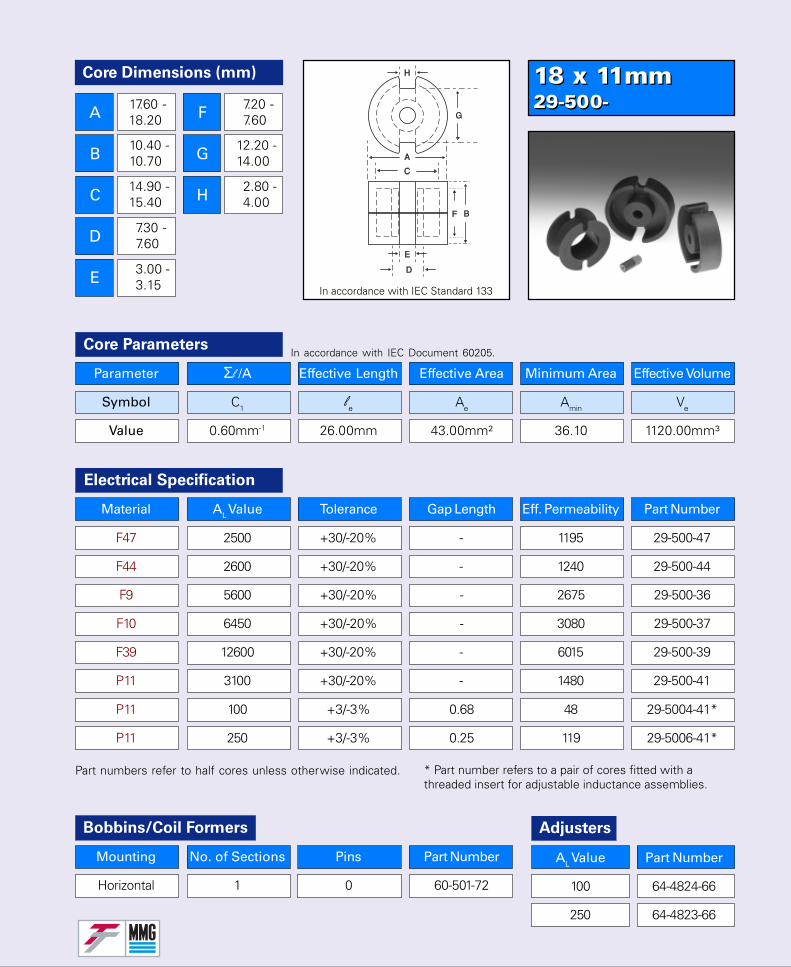
18 x 11mm29-500-18 x 11mm29-500-
Parameter Σl /A Effective Length Effective Area Minimum Area Effective Volume
Symbol C1 le Ae Amin Ve
Value 0.60mm-1 26.00mm 43.00mm² 36.10 1120.00mm³
Core Parameters
Material AL Value Tolerance Gap Length Eff. Permeability Part Number
F47 2500 +30/-20% - 1195 29-500-47
F44 2600 +30/-20% - 1240 29-500-44
F9 5600 +30/-20% - 2675 29-500-36
F10 6450 +30/-20% - 3080 29-500-37
F39 12600 +30/-20% - 6015 29-500-39
P11 3100 +30/-20% - 1480 29-500-41
P11 100 +3/-3% 0.68 48 29-5004-41*
P11 250 +3/-3% 0.25 119 29-5006-41*
Electrical Specification
Part numbers refer to half cores unless otherwise indicated.
In accordance with IEC Document 60205.
Core Dimensions (mm)
A
B
C
D
E
F
G
H
17.60 -18.20
10.40 -10.70
14.90 -15.40
7.30 -7.60
3.00 -3.15
7.20 -7.60
12.20 -14.00
2.80 -4.00
In accordance with IEC Standard 133
Bobbins/Coil Formers
Mounting No. of Sections Pins Part Number
Horizontal 1 0 60-501-72
AL Value Part Number
100 64-4824-66
250 64-4823-66
Adjusters
* Part number refers to a pair of cores fitted with athreaded insert for adjustable inductance assemblies.
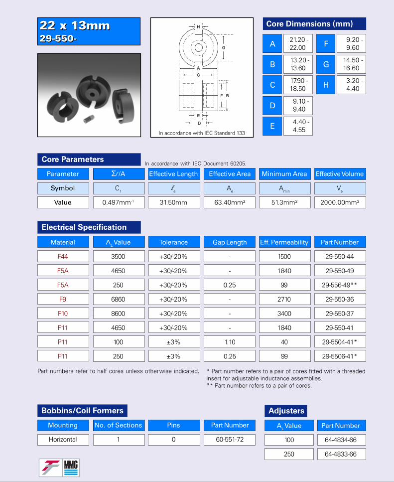
22 x 13mm29-550-22 x 13mm29-550-
Core Dimensions (mm)
A
B
C
D
E
F
G
H
21.20 -22.00
13.20 -13.60
17.90 -18.50
9.10 -9.40
4.40 -4.55
9.20 -9.60
14.50 -16.60
3.20 -4.40
Parameter Σl /A Effective Length Effective Area Minimum Area Effective Volume
Symbol C1 le Ae Amin Ve
Value 0.497mm-1 31.50mm 63.40mm² 51.3mm² 2000.00mm³
Core Parameters
Bobbins/Coil Formers
Mounting No. of Sections Pins Part Number
Horizontal 1 0 60-551-72
In accordance with IEC Document 60205.
In accordance with IEC Standard 133
Electrical Specification
Part numbers refer to half cores unless otherwise indicated. * Part number refers to a pair of cores fitted with a threadedinsert for adjustable inductance assemblies.** Part number refers to a pair of cores.
AL Value Part Number
100 64-4834-66
250 64-4833-66
Adjusters
Material AL Value Tolerance Gap Length Eff. Permeability Part Number
F44 3500 +30/-20% - 1500 29-550-44
F5A 4650 +30/-20% - 1840 29-550-49
F5A 250 +30/-20% 0.25 99 29-556-49**
F9 6860 +30/-20% - 2710 29-550-36
F10 8600 +30/-20% - 3400 29-550-37
P11 4650 +30/-20% - 1840 29-550-41
P11 100 ±3% 1.10 40 29-5504-41*
P11 250 ±3% 0.25 99 29-5506-41*

26 x 16mm29-600-26 x 16mm29-600-
Core Parameters
Electrical Specification
Part numbers refer to half cores unless otherwise indicated.
In accordance with IEC Document 60205.
Core Dimensions (mm)
A
B
C
D
E
F
G
H
25.00 -26.00
15.90 -16.30
21.20 -22.00
11.10 -11.40
5.40 -5.60
11.00 -11.40
17.50 -20.00
3.20 -4.40
In accordance with IEC Standard 133
Bobbins/Coil Formers
Mounting No. of Sections Pins Part Number
Horizontal 1 0 60-601-72
AL Value Part Number
100/250 64-4844-66
400 64-4843-66
Adjusters
* Part number refers to a pair of cores fitted with a nut foradjustable inductance assemblies.** Part number denotes solid core.
Parameter Σl /A Effective Length Effective Area Minimum Area Effective Volume
Symbol C1 le Ae Amin Ve
Value 0.40mm-1 37.50mm 94.00mm² 76.50 3525.00mm³
Solid** 0.35mm-1 39.50mm 112.00mm² 86.50 4410.00mm³
Material AL Value Tolerance Gap Length Eff. Permeability Part Number
F44 4650 +30/-20% - 1480 29-600-44
F5A 6000 +30/-20% - 1910 29-600-49
F9 9000 +30/-20% - 2865 29-600-36
F10 12000 +30/-20% - 3820 29-600-37
F9 10000 ±3% - 2810 29-610-36**
F39 25000 +40/-30% - 7020 29-610-39**
P11 5200 +30/-20% - 1655 29-600-41
P11 100 ±3% 1.60 32 29-6004-41*
P11 250 ±3% 0.48 80 29-6006-41*
P11 400 ±3% 0.25 127 29-6008-41*
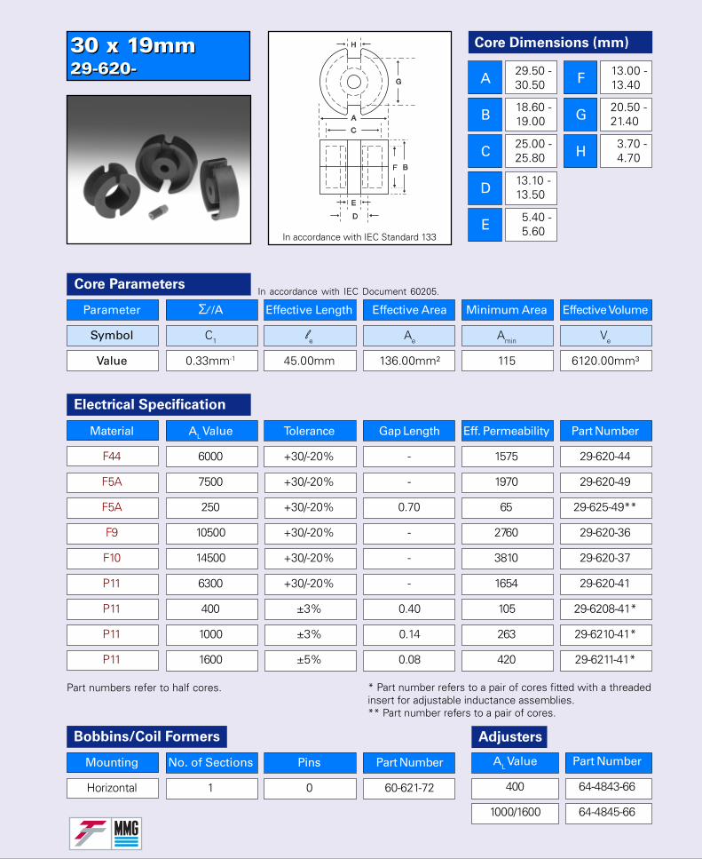
30 x 19mm29-620-30 x 19mm29-620-
Core Dimensions (mm)
A
B
C
D
E
F
G
H
29.50 -30.50
18.60 -19.00
25.00 -25.80
13.10 -13.50
5.40 -5.60
13.00 -13.40
20.50 -21.40
3.70 -4.70
Parameter Σl /A Effective Length Effective Area Minimum Area Effective Volume
Symbol C1 le Ae Amin Ve
Value 0.33mm-1 45.00mm 136.00mm² 115 6120.00mm³
Core Parameters
Electrical Specification
Part numbers refer to half cores.
In accordance with IEC Document 60205.
In accordance with IEC Standard 133
Bobbins/Coil Formers
Mounting No. of Sections Pins Part Number
Horizontal 1 0 60-621-72
Adjusters
* Part number refers to a pair of cores fitted with a threadedinsert for adjustable inductance assemblies.** Part number refers to a pair of cores.
Material AL Value Tolerance Gap Length Eff. Permeability Part Number
F44 6000 +30/-20% - 1575 29-620-44
F5A 7500 +30/-20% - 1970 29-620-49
F5A 250 +30/-20% 0.70 65 29-625-49**
F9 10500 +30/-20% - 2760 29-620-36
F10 14500 +30/-20% - 3810 29-620-37
P11 6300 +30/-20% - 1654 29-620-41
P11 400 ±3% 0.40 105 29-6208-41*
P11 1000 ±3% 0.14 263 29-6210-41*
P11 1600 ±5% 0.08 420 29-6211-41*
AL Value Part Number
400 64-4843-66
1000/1600 64-4845-66
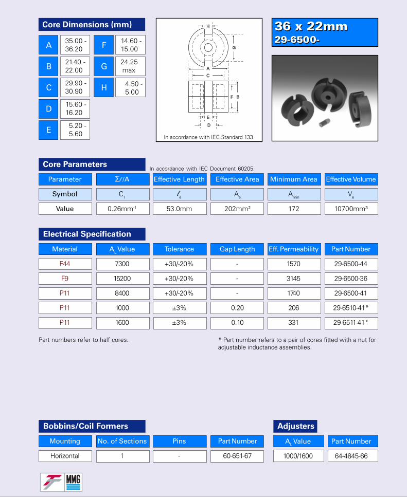
36 x 22mm29-6500-36 x 22mm29-6500-
Parameter Σl /A Effective Length Effective Area Minimum Area Effective Volume
Symbol C1 le Ae Amin Ve
Value 0.26mm-1 53.0mm 202mm² 172 10700mm³
Core Parameters
Electrical Specification
Part numbers refer to half cores.
In accordance with IEC Document 60205.
Bobbins/Coil Formers
Mounting No. of Sections Pins Part Number
Horizontal 1 - 60-651-67
Core Dimensions (mm)
A
B
C
D
E
F
G
H
In accordance with IEC Standard 133
Material AL Value Tolerance Gap Length Eff. Permeability Part Number
F44 7300 +30/-20% - 1570 29-6500-44
F9 15200 +30/-20% - 3145 29-6500-36
P11 8400 +30/-20% - 1740 29-6500-41
P11 1000 ±3% 0.20 206 29-6510-41*
P11 1600 ±3% 0.10 331 29-6511-41*
Adjusters
AL Value Part Number
1000/1600 64-4845-66
35.00 -36.20
21.40 -22.00
29.90 -30.90
15.60 -16.20
5.20 -5.60
14.60 -15.00
24.25 max
4.50 -5.00
* Part number refers to a pair of cores fitted with a nut foradjustable inductance assemblies.
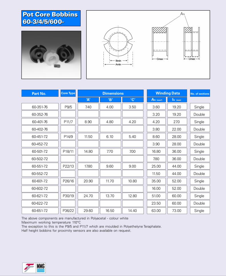
Pot Core Bobbins60-3/4/5/600-Pot Core Bobbins60-3/4/5/600-
1234567123456712345671234567
No. of sectionsPart No. Core Type Dimensions
‘A’ ‘B’ ‘C’
Winding Data
AN (mm²) IN (mm)
The above components are manufactured in Polyacetal - colour whiteMaximum working temperature 110°CThe exception to this is the P9/5 and P11/7 which are moulded in Polyethelyne Teraphalate.Half height bobbins for proximity sensors are also available on request.
1234123412341234
AN
60-351-76 P9/5 7.40 4.00 3.50 3.60 19.20 Single
60-352-76 3.20 19.20 Double
60-401-76 P11/7 8.90 4.80 4.20 4.20 27.0 Single
60-402-76 3.80 22.00 Double
60-451-72 P14/9 11.50 6.10 5.40 8.60 28.00 Single
60-452-72 3.90 28.00 Double
60-501-72 P18/11 14.80 7.70 7.00 16.80 36.00 Single
60-502-72 7.80 36.00 Double
60-551-72 P22/13 17.80 9.60 9.00 25.00 44.00 Single
60-552-72 11.50 44.00 Double
60-601-72 P26/16 20.90 11.70 10.80 35.00 52.00 Single
60-602-72 16.00 52.00 Double
60-621-72 P30/19 24.70 13.70 12.80 51.00 60.00 Single
60-622-72 23.50 60.00 Double
60-651-72 P36/22 29.60 16.50 14.40 63.00 73.00 Single
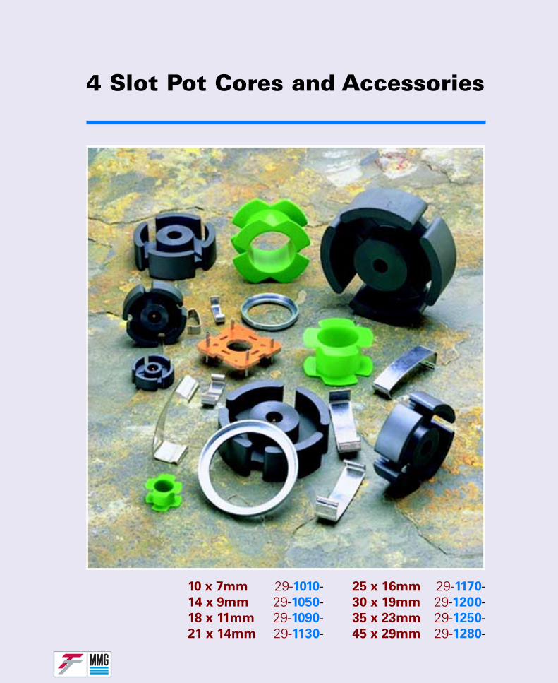
4 Slot Pot Cores and Accessories
25 x 16mm 29-1170-30 x 19mm 29-1200-35 x 23mm 29-1250-45 x 29mm 29-1280-
10 x 7mm 29-1010-14 x 9mm 29-1050-18 x 11mm 29-1090-21 x 14mm 29-1130-
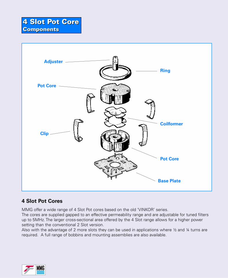
4 Slot Pot CoreComponents4 Slot Pot CoreComponents
4 Slot Pot Cores
Pot Core
Adjuster
Ring
Clip
Base Plate
Pot Core
Coilformer
MMG offer a wide range of 4 Slot Pot cores based on the old ‘VINKOR’ series.The cores are supplied gapped to an effective permeability range and are adjustable for tuned filtersup to 5MHz. The larger cross-sectional area offered by the 4 Slot range allows for a higher powersetting than the conventional 2 Slot version.Also with the advantage of 2 more slots they can be used in applications where ½ and ¼ turns arerequired. A full range of bobbins and mounting assemblies are also available.
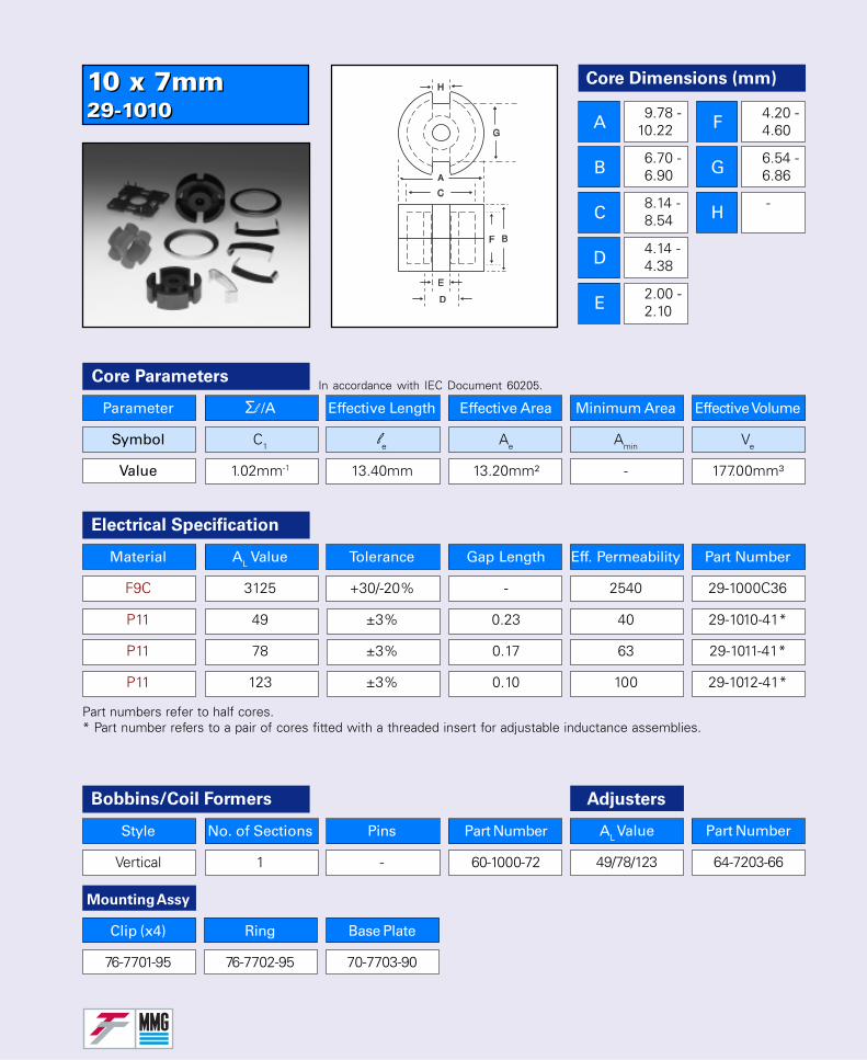
10 x 7mm29-101010 x 7mm29-1010
Core Dimensions (mm)
A
B
C
D
E
F
G
H
9.78 -10.22
6.70 -6.90
8.14 -8.54
4.14 -4.38
2.00 -2.10
4.20 -4.60
6.54 -6.86
-
Parameter Σl /A Effective Length Effective Area Minimum Area Effective Volume
Symbol C1 le Ae Amin Ve
Value 1.02mm-1 13.40mm 13.20mm² - 177.00mm³
Core Parameters
Electrical Specification
Part numbers refer to half cores.* Part number refers to a pair of cores fitted with a threaded insert for adjustable inductance assemblies.
In accordance with IEC Document 60205.
Material AL Value Tolerance Gap Length Eff. Permeability Part Number
F9C 3125 +30/-20% - 2540 29-1000C36
P11 49 ±3% 0.23 40 29-1010-41*
P11 78 ±3% 0.17 63 29-1011-41*
P11 123 ±3% 0.10 100 29-1012-41*
Bobbins/Coil Formers
Style No. of Sections Pins Part Number
Vertical 1 - 60-1000-72
AL Value
49/78/123
Adjusters
Part Number
64-7203-66
Mounting Assy
Clip (x4) Ring Base Plate
76-7701-95 76-7702-95 70-7703-90
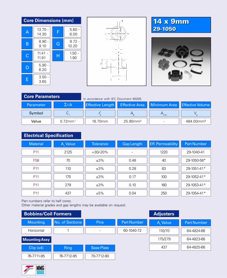
14 x 9mm29-105014 x 9mm29-1050
Parameter Σl /A Effective Length Effective Area Minimum Area Effective Volume
Symbol C1 le Ae Amin Ve
Value 0.72mm-1 18.70mm 25.90mm² - 484.00mm³
Core Parameters
Electrical Specification
Part numbers refer to half cores.Other material grades and gap lengths may be available on request.
In accordance with IEC Document 60205.
Bobbins/Coil Formers
Mounting No. of Sections Pins Part Number
Horizontal 1 - 60-1040-72
Core Dimensions (mm)
A
B
C
D
E
F
G
H
13.70 -14.30
8.90 -9.10
11.41 -11.91
5.90 -6.20
3.50 -3.65
5.60 -6.00
9.72 -10.20
1.50 -1.90
Material AL Value Tolerance Gap Length Eff. Permeability Part Number
P11 2125 +30/-20% - 1220 29-1040-41
F58 70 ±3% 0.48 40 29-1050-58*
P11 110 ±3% 0.28 63 29-1051-41*
P11 175 ±3% 0.17 100 29-1052-41*
P11 279 ±3% 0.10 160 29-1053-41*
P11 437 ±5% 0.04 250 29-1054-41*
AL Value
110/70
175/279
437
Adjusters
Part Number
64-4824-66
64-4823-66
64-4825-66
Mounting Assy
Clip (x4) Ring Base Plate
76-7711-95 76-7712-95 70-7712-90
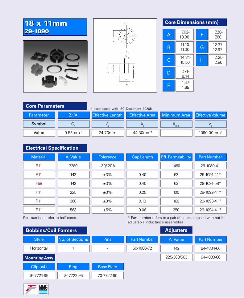
18 x 11mm29-109018 x 11mm29-1090
Core Dimensions (mm)
A
B
C
D
E
F
G
H
17.62-18.38
7.20-7.60
12.37-12.97
2.20-2.80
Core ParametersIn accordance with IEC Document 60205.
Electrical Specification
Part numbers refer to half cores. * Part number refers to a pair of cores supplied with nut foradjustable inductance assemblies.
Material AL Value Tolerance Gap Length Eff. Permeability Part Number
P11 3280 +30/-20% - 1460 29-1080-41
P11 142 ±3% 0.40 63 29-1091-41*
F58 142 ±3% 0.40 63 29-1091-58*
P11 225 ±3% 0.25 100 29-1092-41*
P11 360 ±3% 0.13 160 29-1093-41*
P11 563 ±5% 0.06 250 29-1094-41*
Parameter Σl /A Effective Length Effective Area Minimum Area Effective Volume
Symbol C1 le Ae Amin Ve
Value 0.55mm-1 24.70mm 44.30mm² - 1090.00mm³
Bobbins/Coil Formers
Style No. of Sections Pins Part Number
Horizontal 1 - 60-1080-72
AL Value
142
225/360/563
Adjusters
Part Number
64-4834-66
64-4833-66Mounting Assy
Clip (x4) Ring Base Plate
76-7721-95 76-7722-95 70-7722-90
11.10-11.30
14.84-15.50
7.74-8.14
4.47-4.65
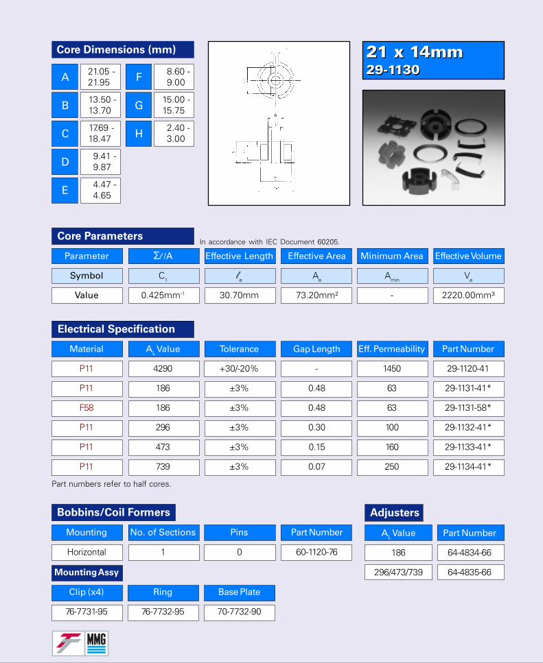
21 x 14mm29-113021 x 14mm29-1130
Parameter Σl /A Effective Length Effective Area Minimum Area Effective Volume
Symbol C1 le Ae Amin Ve
Value 0.425mm-1 30.70mm 73.20mm² - 2220.00mm³
Core Parameters
Electrical Specification
Part numbers refer to half cores.
In accordance with IEC Document 60205.
Core Dimensions (mm)
A
B
C
D
E
F
G
H
21.05 -21.95
13.50 -13.70
17.69 -18.47
9.41 -9.87
4.47 -4.65
8.60 -9.00
15.00 -15.75
2.40 -3.00
Bobbins/Coil Formers
Mounting No. of Sections Pins Part Number
Horizontal 1 0 60-1120-76
AL Value Part Number
186 64-4834-66
296/473/739 64-4835-66
Adjusters
Material AL Value Tolerance Gap Length Eff. Permeability Part Number
P11 4290 +30/-20% - 1450 29-1120-41
P11 186 ±3% 0.48 63 29-1131-41*
F58 186 ±3% 0.48 63 29-1131-58*
P11 296 ±3% 0.30 100 29-1132-41*
P11 473 ±3% 0.15 160 29-1133-41*
P11 739 ±3% 0.07 250 29-1134-41*
Mounting Assy
Clip (x4) Ring Base Plate
76-7731-95 76-7732-95 70-7732-90
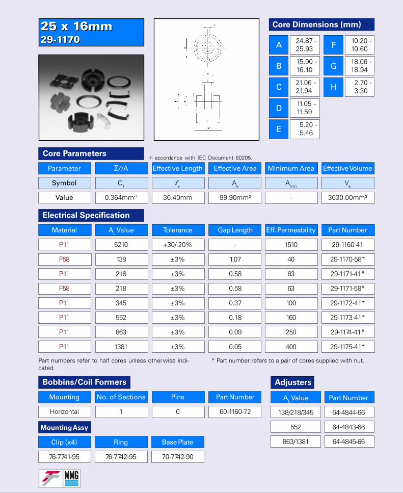
25 x 16mm29-117025 x 16mm29-1170
Core Dimensions (mm)
A
B
C
D
E
F
G
H
24.87 -25.93
15.90 -16.10
21.06 -21.94
11.05 -11.59
5.20 -5.46
10.20 -10.60
18.06 -18.94
2.70 -3.30
Parameter Σl /A Effective Length Effective Area Minimum Area Effective Volume
Symbol C1 le Ae Amin Ve
Value 0.364mm-1 36.40mm 99.90mm² - 3630.00mm³
Core Parameters
Bobbins/Coil Formers
Mounting No. of Sections Pins Part Number
Horizontal 1 0 60-1160-72
In accordance with IEC Document 60205.
Electrical Specification
Part numbers refer to half cores unless otherwise indi-cated.
* Part number refers to a pair of cores supplied with nut.
Adjusters
Material AL Value Tolerance Gap Length Eff. Permeability Part Number
P11 5210 +30/-20% - 1510 29-1160-41
F58 138 ±3% 1.07 40 29-1170-58*
P11 218 ±3% 0.58 63 29-1171-41*
F58 218 ±3% 0.58 63 29-1171-58*
P11 345 ±3% 0.37 100 29-1172-41*
P11 552 ±3% 0.18 160 29-1173-41*
P11 863 ±3% 0.09 250 29-1174-41*
P11 1381 ±3% 0.05 400 29-1175-41*
Mounting Assy
Clip (x4) Ring Base Plate
76-7741-95 76-7742-95 70-7742-90
AL Value Part Number
138/218/345 64-4844-66
552 64-4843-66
863/1381 64-4845-66
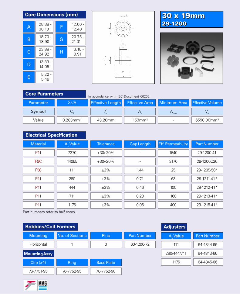
30 x 19mm29-120030 x 19mm29-1200
Parameter Σl /A Effective Length Effective Area Minimum Area Effective Volume
Symbol C1 le Ae Amin Ve
Value 0.283mm-1 43.20mm 153mm² - 6590.00mm³
Core Parameters
Electrical Specification
Part numbers refer to half cores.
In accordance with IEC Document 60205.
Core Dimensions (mm)
A
B
C
D
E
F
G
H
28.88 -30.10
18.70 -18.90
23.88 -24.92
13.39 -14.05
5.20 -5.46
12.00 -12.40
20.75 -21.01
3.10 -3.91
Bobbins/Coil Formers
Mounting No. of Sections Pins Part Number
Horizontal 1 0 60-1200-72
Adjusters
Material AL Value Tolerance Gap Length Eff. Permeability Part Number
P11 7270 +30/-20% - 1640 29-1200-41
F9C 14065 +30/-20% - 3170 29-1200C36
F58 111 ±3% 1.44 25 29-1205-58*
P11 280 ±3% 0.71 63 29-1211-41*
P11 444 ±3% 0.46 100 29-1212-41*
P11 711 ±3% 0.23 160 29-1213-41*
P11 1176 ±3% 0.06 400 29-1215-41*
Mounting Assy
Clip (x4) Ring Base Plate
76-7751-95 76-7752-95 70-7752-90
AL Value Part Number
111 64-4844-66
280/444/711 64-4843-66
1176 64-4845-66

35 x 23mm29-12535 x 23mm29-1250
Core Dimensions (mm)
A
B
C
D
E
F
G
H
34.75 -36.25
22.70 -22.92
28.70 -29.92
15.80 -16.61
5.20 -5.46
14.58 -14.98
25.17 -25.43
3.61 -4.39
Parameter Σl /A Effective Length Effective Area Minimum Area Effective Volume
Symbol C1 le Ae Amin Ve
Value 0.236mm-1 52.50mm 223mm² - 11,700mm³
Core ParametersIn accordance with IEC Document 60205.
Electrical Specification
Part numbers refer to half cores.
Material AL Value Tolerance Gap Length Eff. Permeability Part Number
F9C 16690 +30/-20% - 3135 29-1240C36
P11 8690 +30/-20% - 1632 29-1240-41
F58 213 ±3% - 40 29-1250-58*
F58 336 ±3% 0.86 63 29-1251-58*
P11 336 ±3% 0.86 63 29-1251-41*
P11 533 ±3% 0.55 100 29-1252-41*
P11 852 ±3% 0.28 160 29-1253-41*
P11 1331 ±-3% 0.14 250 29-1254-41*
P11 2130 ±3% 0.08 400 29-1255-41*
Bobbins/Coil Formers
Mounting No. of Sections Pins Part Number
Horizontal 1 0 60-1240-72
Adjusters
Mounting Assy
Clip (x4) Ring Base Plate
76-7761-95 76-7762-95 70-7762-90
AL Value Part Number
213 64-4844-66
336/533 64-4843-66
852/1331/2130 64-4863-66
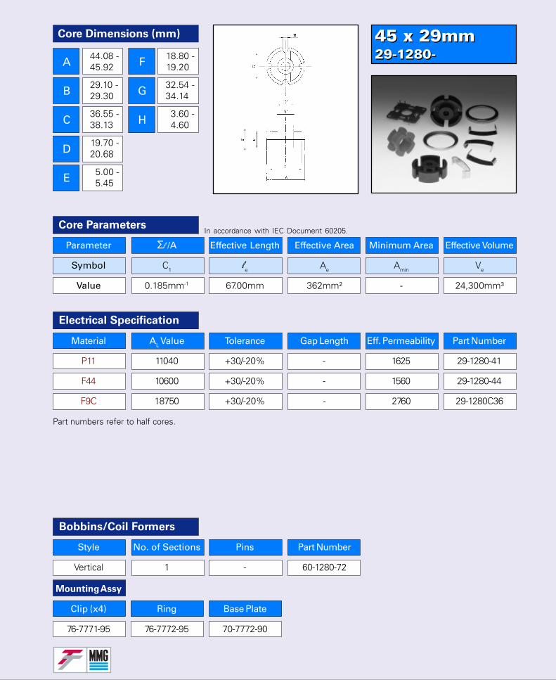
45 x 29mm29-1280-45 x 29mm29-1280-
Parameter Σl /A Effective Length Effective Area Minimum Area Effective Volume
Symbol C1 le Ae Amin Ve
Value 0.185mm-1 67.00mm 362mm² - 24,300mm³
Core Parameters
Material AL Value Tolerance Gap Length Eff. Permeability Part Number
P11 11040 +30/-20% - 1625 29-1280-41
F44 10600 +30/-20% - 1560 29-1280-44
F9C 18750 +30/-20% - 2760 29-1280C36
Electrical Specification
Part numbers refer to half cores.
In accordance with IEC Document 60205.
Bobbins/Coil Formers
Style No. of Sections Pins Part Number
Vertical 1 - 60-1280-72
Core Dimensions (mm)
A
B
C
D
E
F
G
H
44.08 -45.92
29.10 -29.30
36.55 -38.13
19.70 -20.68
5.00 -5.45
18.80 -19.20
32.54 -34.14
3.60 -4.60
Mounting Assy
Clip (x4) Ring Base Plate
76-7771-95 76-7772-95 70-7772-90
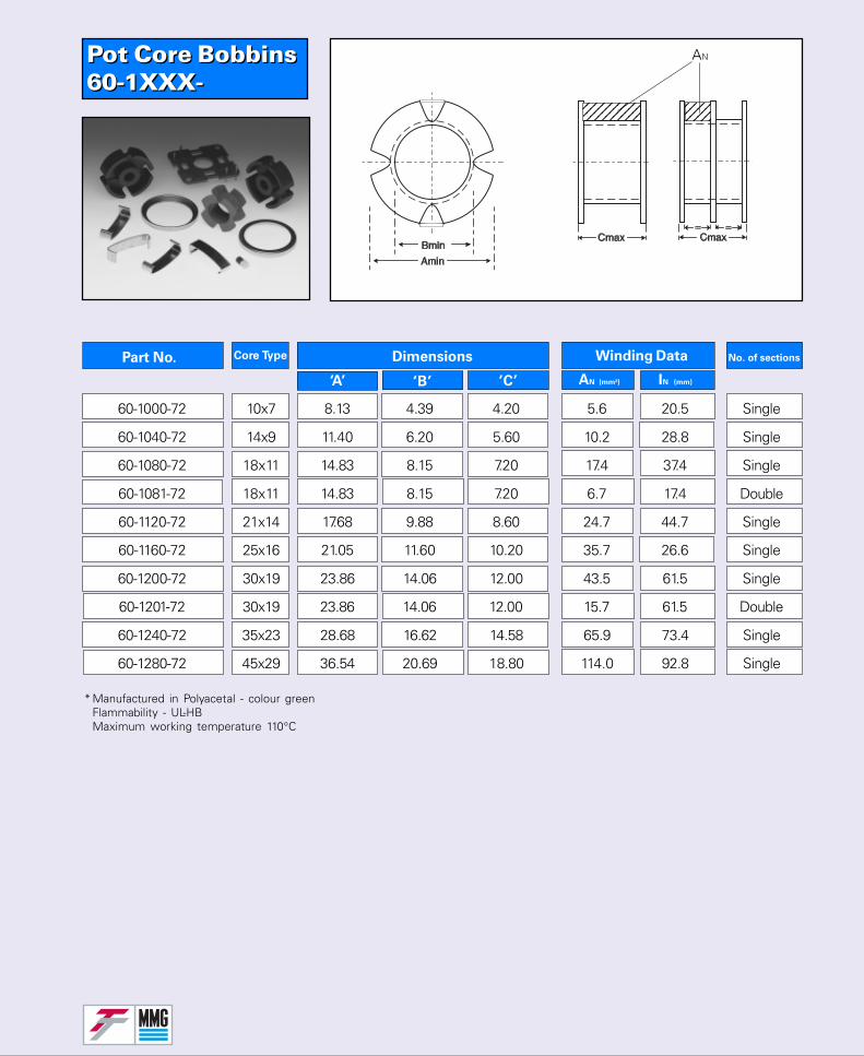
Pot Core Bobbins60-1XXX-Pot Core Bobbins60-1XXX-
No. of sectionsPart No. Core Type Dimensions
‘A’ ‘B’ ‘C’
Winding Data
AN (mm²) IN (mm)
* Manufactured in Polyacetal - colour greenFlammability - UL-HBMaximum working temperature 110°C
60-1000-72 10x7 8.13 4.39 4.20 5.6 20.5 Single
60-1040-72 14x9 11.40 6.20 5.60 10.2 28.8 Single
60-1080-72 18x11 14.83 8.15 7.20 17.4 37.4 Single
60-1081-72 18x11 14.83 8.15 7.20 6.7 17.4 Double
60-1120-72 21x14 17.68 9.88 8.60 24.7 44.7 Single
60-1160-72 25x16 21.05 11.60 10.20 35.7 26.6 Single
60-1200-72 30x19 23.86 14.06 12.00 43.5 61.5 Single
60-1201-72 30x19 23.86 14.06 12.00 15.7 61.5 Double
60-1240-72 35x23 28.68 16.62 14.58 65.9 73.4 Single
60-1280-72 45x29 36.54 20.69 18.80 114.0 92.8 Single
123456789123456789123456789
1234123412341234
AN
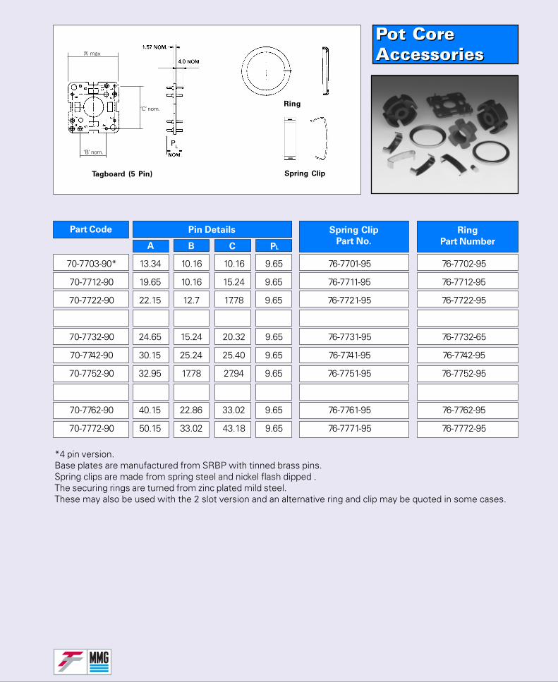
Pot CoreAccessoriesPot CoreAccessories
Spring Clip
Part No.
Part Code Ring
Part NumberA B C PL
Pin Details
*4 pin version.Base plates are manufactured from SRBP with tinned brass pins.Spring clips are made from spring steel and nickel flash dipped .The securing rings are turned from zinc plated mild steel.These may also be used with the 2 slot version and an alternative ring and clip may be quoted in some cases.
‘A’ max
‘B’ nom.
Tagboard (5 Pin)
‘C’ nom.Ring
Spring Clip
PL
70-7703-90* 13.34 10.16 10.16 9.65 76-7701-95 76-7702-95
70-7712-90 19.65 10.16 15.24 9.65 76-7711-95 76-7712-95
70-7722-90 22.15 12.7 17.78 9.65 76-7721-95 76-7722-95
70-7732-90 24.65 15.24 20.32 9.65 76-7731-95 76-7732-65
70-7742-90 30.15 25.24 25.40 9.65 76-7741-95 76-7742-95
70-7752-90 32.95 17.78 27.94 9.65 76-7751-95 76-7752-95
70-7762-90 40.15 22.86 33.02 9.65 76-7761-95 76-7762-95
70-7772-90 50.15 33.02 43.18 9.65 76-7771-95 76-7772-95
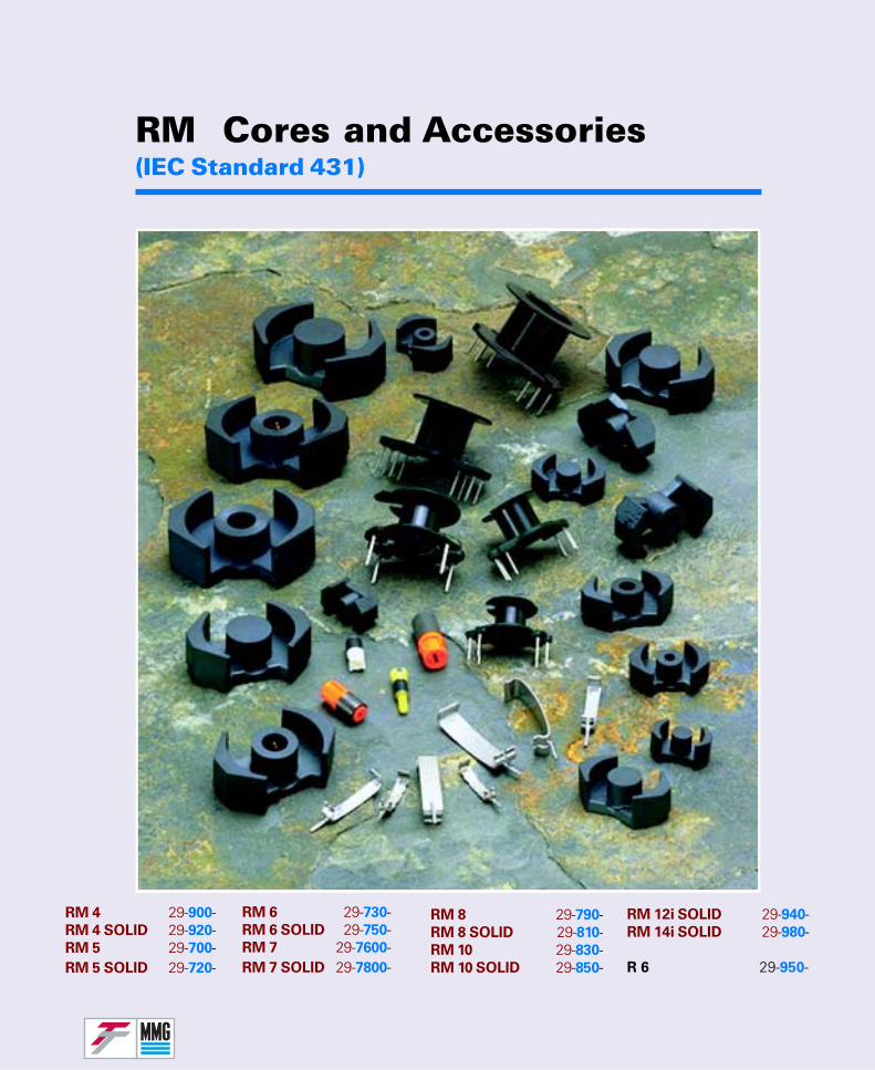
RM Cores and Accessories(IEC Standard 431)
RM 6 29-730-RM 6 SOLID 29-750-RM 7 29-7600-RM 7 SOLID 29-7800-
RM 4 29-900-RM 4 SOLID 29-920-RM 5 29-700-RM 5 SOLID 29-720-
RM 8 29-790-RM 8 SOLID 29-810-RM 10 29-830-RM 10 SOLID 29-850-
RM 12i SOLID 29-940-RM 14i SOLID 29-980-
R 6 29-950-
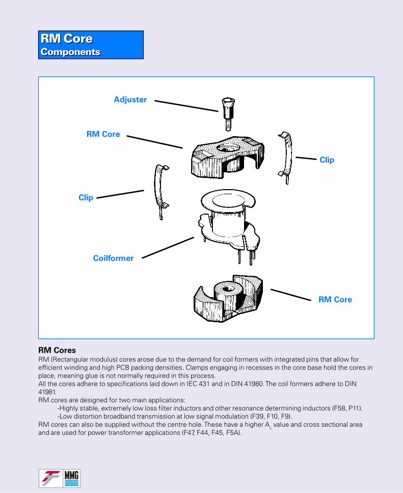
RM CoreComponentsRM CoreComponents
RM CoresRM (Rectangular modulus) cores arose due to the demand for coil formers with integrated pins that allow forefficient winding and high PCB packing densities. Clamps engaging in recesses in the core base hold the cores inplace, meaning glue is not normally required in this process.All the cores adhere to specifications laid down in IEC 431 and in DIN 41980. The coil formers adhere to DIN41981.RM cores are designed for two main applications:
-Highly stable, extremely low loss filter inductors and other resonance determining inductors (F58, P11).-Low distortion broadband transmission at low signal modulation (F39, F10, F9).
RM cores can also be supplied without the centre hole. These have a higher AL value and cross sectional areaand are used for power transformer applications (F47, F44, F45, F5A).
RM Core
Coilformer
RM Core
Clip
Clip
Adjuster
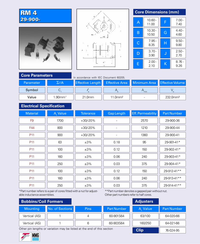
RM 429-900-RM 429-900-
Part Number
64-020-66
64-021-66
76-024-95
Parameter Σl /A Effective Length Effective Area Minimum Area Effective Volume
Symbol C1 le Ae Amin Ve
Value 1.90mm-1 21.0mm 11.0mm² - 232.0mm³
Core Parameters
Electrical Specification
In accordance with IEC Document 60205.
Bobbins/Coil Formers Adjusters
Material AL Value Tolerance Gap Length Eff. Permeability Part Number
F9 1700 +30/-20% - 2570 29-900-36
F44 800 +30/-20% - 1210 29-900-44
P11 900 +30/-20% - 1360 29-900-41
P11 63 ±3% 0.18 95 29-901-41*
P11 100 ±3% 0.12 150 29-902-41*
P11 160 ±3% 0.06 240 29-903-41*
P11 250 ±3% 0.03 375 29-904-41*
P11 100 ±3% 0.12 150 29-912-41**
P11 160 ±3% 0.06 240 29-913-41**
P11 250 ±3% 0.03 375 29-914-41**
Mounting No. of Sections Pins Part Number
Vertical (AS) 1 4 60-901S64
Vertical (AS) 1 6 60-903S64
Other pin lengths or variation may be listed at the end of this section
AL Value
63/100
160/250
Clip
*Part number refers to a pair of cores fitted with a nut for adjust-able inductance assemblies.
**Part number denotes a gapped pair without nut.Other part numbers refer to half cores.
Core Dimensions (mm)
A
B
C
D
E
F
G
H
J
K
10.60 -11.00
10.30 -10.50
7.95 -8.35
3.70 -3.90
2.00 -2.10
7.00 -7.40
4.40 -4.60
9.50 -9.80
2.50 -2.70
8.76 -9.26
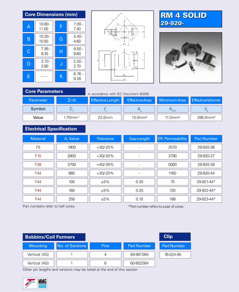
RM 4 SOLID29-920-RM 4 SOLID29-920-
76-024-95
Parameter Σl /A Effective Length Effective Area Minimum Area Effective Volume
Symbol C1 le Ae Amin Ve
Value 1.70mm-1 22.0mm 13.0mm² 11.3mm² 286.0mm³
Core ParametersIn accordance with IEC Document 60205.
Part numbers refer to half cores. *Part number refers to a pair of cores.
Other pin lengths and versions may be listed at the end of this section
Electrical Specification
Material AL Value Tolerance Gap Length Eff. Permeability Part Number
F9 1900 +30/-20% - 2570 29-920-36
F10 2800 +30/-20% - 3790 29-920-37
F39 3700 +40/-30% - 5000 29-920-39
F44 860 +30/-20% - 1160 29-920-44
F44 100 ±5% 0.35 75 29-921-44*
F44 160 ±5% 0.20 120 29-922-44*
F44 250 ±5% 0.10 188 29-923-44*
Bobbins/Coil Formers
Mounting No. of Sections Pins Part Number
Vertical (AS) 1 4 60-901S64
Vertical (AS) 1 6 60-902S64
Clip
Part Number
Core Dimensions (mm)
A
B
C
D
E
F
G
H
J
K
10.60 -11.00
10.30 -10.50
7.95 -8.35
3.70 -3.90
7.00 -7.40
4.40 -4.60
9.50 -9.80
2.50 -2.70
8.76 -9.26
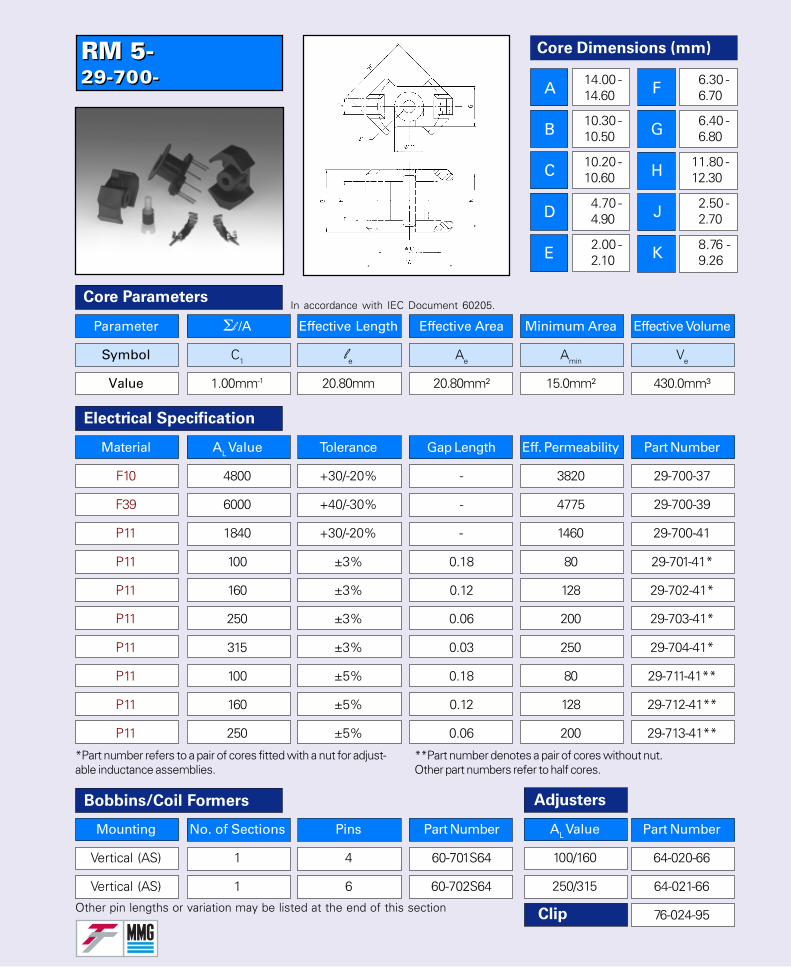
RM 5-29-700-RM 5-29-700-
Parameter Σl /A Effective Length Effective Area Minimum Area Effective Volume
Symbol C1 le Ae Amin Ve
Value 1.00mm-1 20.80mm 20.80mm² 15.0mm² 430.0mm³
Core Parameters
Electrical Specification
In accordance with IEC Document 60205.
Bobbins/Coil Formers Adjusters
Material AL Value Tolerance Gap Length Eff. Permeability Part Number
F10 4800 +30/-20% - 3820 29-700-37
F39 6000 +40/-30% - 4775 29-700-39
P11 1840 +30/-20% - 1460 29-700-41
P11 100 ±3% 0.18 80 29-701-41*
P11 160 ±3% 0.12 128 29-702-41*
P11 250 ±3% 0.06 200 29-703-41*
P11 315 ±3% 0.03 250 29-704-41*
P11 100 ±5% 0.18 80 29-711-41**
P11 160 ±5% 0.12 128 29-712-41**
P11 250 ±5% 0.06 200 29-713-41**
Other pin lengths or variation may be listed at the end of this section
AL Value
100/160
250/315
Clip
*Part number refers to a pair of cores fitted with a nut for adjust-able inductance assemblies.
**Part number denotes a pair of cores without nut.Other part numbers refer to half cores.
Part Number
64-020-66
64-021-66
76-024-95
Mounting No. of Sections Pins Part Number
Vertical (AS) 1 4 60-701S64
Vertical (AS) 1 6 60-702S64
Core Dimensions (mm)
A
B
C
D
E
F
G
H
J
K
14.00 -14.60
10.30 -10.50
10.20 -10.60
4.70 -4.90
2.00 -2.10
6.30 -6.70
6.40 -6.80
11.80 -12.30
2.50 -2.70
8.76 -9.26
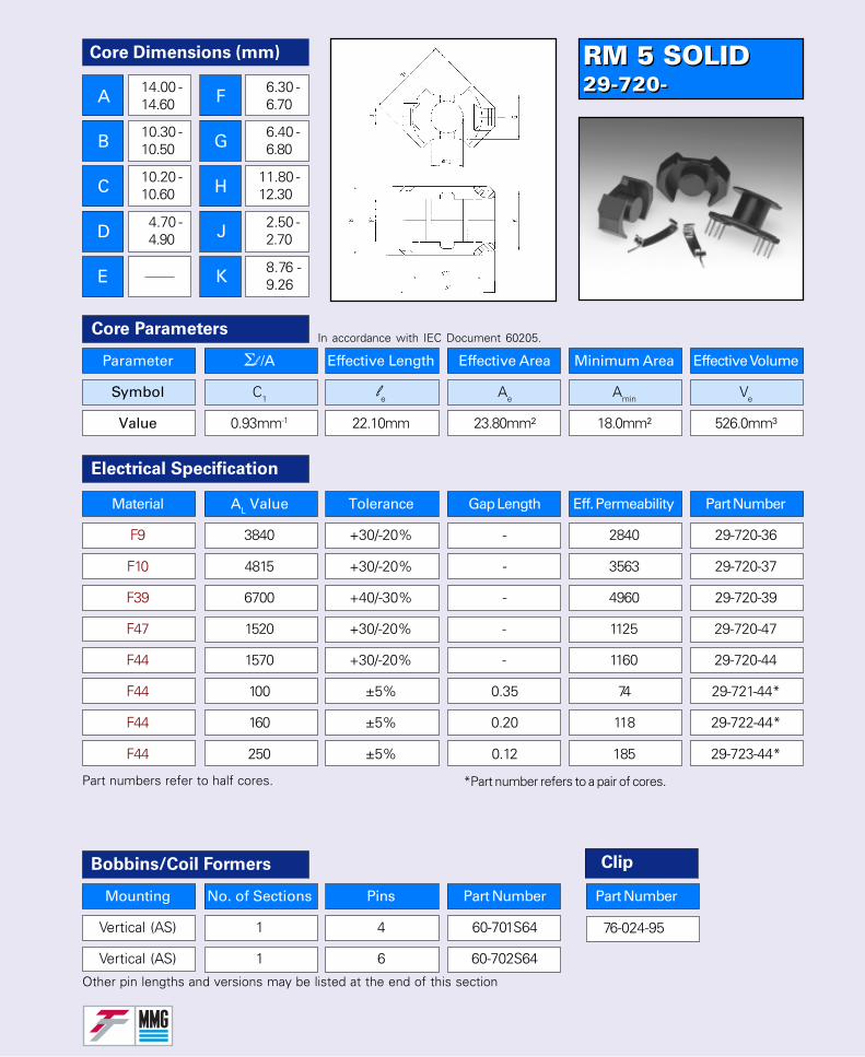
RM 5 SOLID29-720-RM 5 SOLID29-720-
76-024-95
Mounting No. of Sections Pins Part Number
Vertical (AS) 1 4 60-701S64
Vertical (AS) 1 6 60-702S64
Parameter Σl /A Effective Length Effective Area Minimum Area Effective Volume
Symbol C1 le Ae Amin Ve
Value 0.93mm-1 22.10mm 23.80mm² 18.0mm² 526.0mm³
Core ParametersIn accordance with IEC Document 60205.
Part numbers refer to half cores. *Part number refers to a pair of cores.
Other pin lengths and versions may be listed at the end of this section
Electrical Specification
Material AL Value Tolerance Gap Length Eff. Permeability Part Number
F9 3840 +30/-20% - 2840 29-720-36
F10 4815 +30/-20% - 3563 29-720-37
F39 6700 +40/-30% - 4960 29-720-39
F47 1520 +30/-20% - 1125 29-720-47
F44 1570 +30/-20% - 1160 29-720-44
F44 100 ±5% 0.35 74 29-721-44*
F44 160 ±5% 0.20 118 29-722-44*
F44 250 ±5% 0.12 185 29-723-44*
Bobbins/Coil Formers Clip
Part Number
Core Dimensions (mm)
A
B
C
D
E
F
G
H
J
K
14.00 -14.60
10.30 -10.50
10.20 -10.60
4.70 -4.90
6.30 -6.70
6.40 -6.80
11.80 -12.30
2.50 -2.70
8.76 -9.26
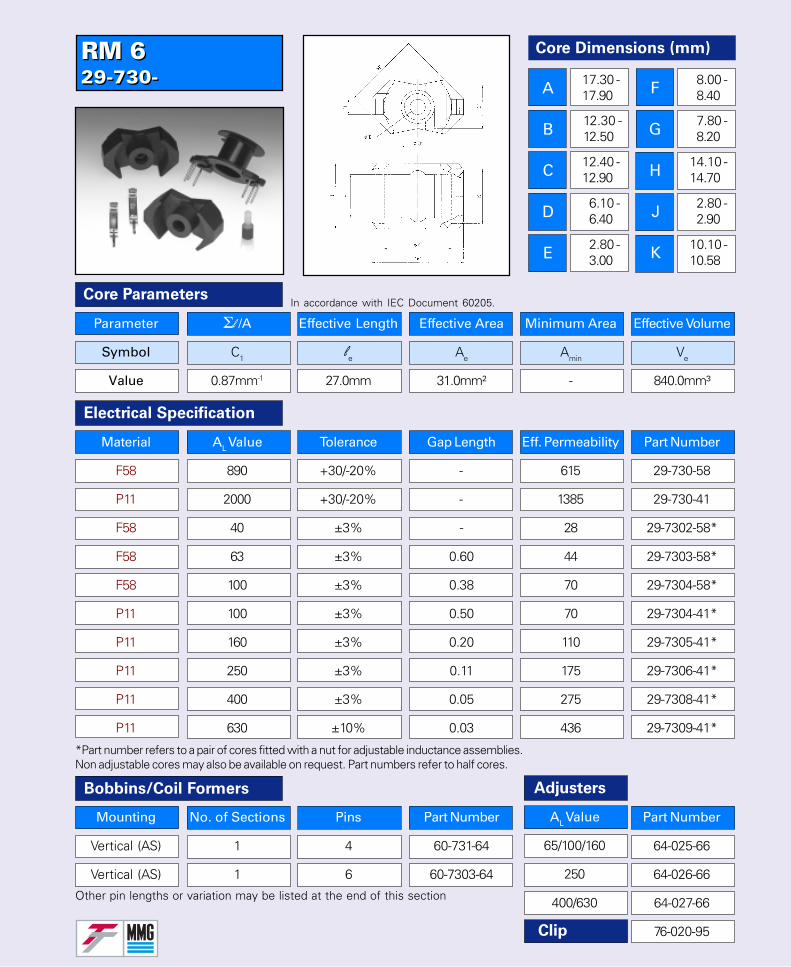
RM 629-730-RM 629-730-
*Part number refers to a pair of cores fitted with a nut for adjustable inductance assemblies.Non adjustable cores may also be available on request. Part numbers refer to half cores.
Parameter Σl /A Effective Length Effective Area Minimum Area Effective Volume
Symbol C1 le Ae Amin Ve
Value 0.87mm-1 27.0mm 31.0mm² - 840.0mm³
Core Parameters
Electrical Specification
In accordance with IEC Document 60205.
Bobbins/Coil Formers Adjusters
Material AL Value Tolerance Gap Length Eff. Permeability Part Number
F58 890 +30/-20% - 615 29-730-58
P11 2000 +30/-20% - 1385 29-730-41
F58 40 ±3% - 28 29-7302-58*
F58 63 ±3% 0.60 44 29-7303-58*
F58 100 ±3% 0.38 70 29-7304-58*
Other pin lengths or variation may be listed at the end of this section
Clip
Mounting No. of Sections Pins Part Number
Vertical (AS) 1 4 60-731-64
Vertical (AS) 1 6 60-7303-64
AL Value
65/100/160
250
400/630
Part Number
64-025-66
64-026-66
64-027-66
76-020-95
P11 100 ±3% 0.50 70 29-7304-41*
P11 160 ±3% 0.20 110 29-7305-41*
P11 250 ±3% 0.11 175 29-7306-41*
P11 400 ±3% 0.05 275 29-7308-41*
P11 630 ±10% 0.03 436 29-7309-41*
Core Dimensions (mm)
A
B
C
D
E
F
G
H
J
K
17.30 -17.90
12.30 -12.50
12.40 -12.90
6.10 -6.40
2.80 -3.00
8.00 -8.40
7.80 -8.20
14.10 -14.70
2.80 -2.90
10.10 -10.58
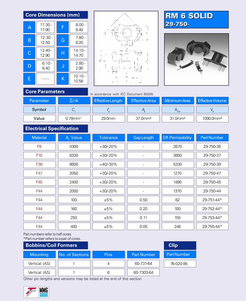
RM 6 SOLID29-750-RM 6 SOLID29-750-
76-020-95
Mounting No. of Sections Pins Part Number
Vertical (AS) 1 4 60-731-64
Vertical (AS) 1 6 60-7303-64
Parameter Σl /A Effective Length Effective Area Minimum Area Effective Volume
Symbol C1 le Ae Amin Ve
Value 0.78mm-1 29.0mm 37.0mm² 31.0mm² 1090.0mm³
Core ParametersIn accordance with IEC Document 60205.
Other pin lengths and versions may be listed at the end of this section
Electrical Specification
Bobbins/Coil Formers
F44 2000 +30/-20% - 1370 29-750-44
F44 100 ±5% 0.50 62 29-751-44*
F44 160 ±5% 0.20 100 29-752-44*
F44 250 ±5% 0.11 155 29-753-44*
F44 400 ±5% 0.05 248 29-755-44*
Material AL Value Tolerance Gap Length Eff. Permeability Part Number
F9 4300 +30/-20% - 2670 29-750-36
F10 6200 +30/-20% - 3850 29-750-37
F39 8600 +40/-30% - 5330 29-750-39
F47 2050 +30/-20% - 1270 29-750-47
F45 2400 +30/-20% - 1490 29-750-45
Part numbers refer to half cores.*Part number refers to a pair of cores.
Clip
Part Number
Core Dimensions (mm)
A
B
C
D
E
F
G
H
J
K
17.30 -17.90
12.30 -12.50
12.40 -12.90
6.10 -6.40
8.00 -8.40
7.80 -8.20
14.10 -14.70
2.80 -2.90
10.10 -10.58
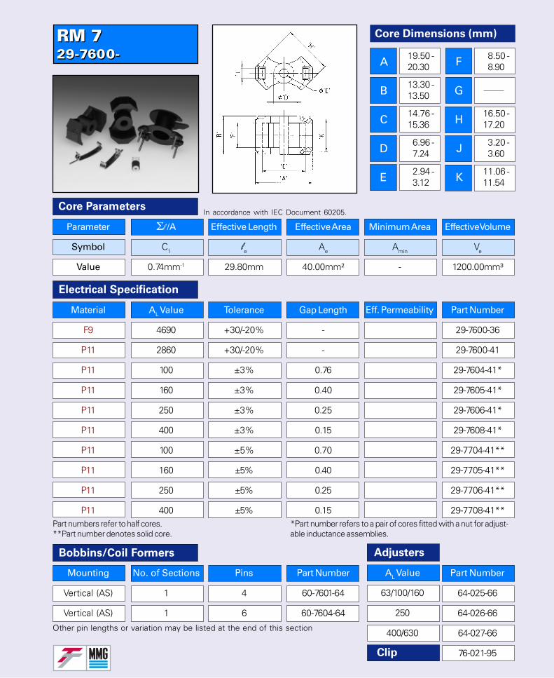
RM 729-7600-RM 729-7600-
Part numbers refer to half cores.**Part number denotes solid core.
Parameter Σl /A Effective Length Effective Area Minimum Area Effective Volume
Symbol C1 le Ae Amin Ve
Value 0.74mm-1 29.80mm 40.00mm² - 1200.00mm³
Core Parameters
Electrical Specification
In accordance with IEC Document 60205.
Bobbins/Coil Formers Adjusters
Other pin lengths or variation may be listed at the end of this section
Clip
Mounting No. of Sections Pins Part Number
Vertical (AS) 1 4 60-7601-64
Vertical (AS) 1 6 60-7604-64
AL Value
63/100/160
250
400/630
Part Number
64-025-66
64-026-66
64-027-66
76-021-95
Material AL Value Tolerance Gap Length Eff. Permeability Part Number
F9 4690 +30/-20% - 29-7600-36
P11 2860 +30/-20% - 29-7600-41
P11 100 ±3% 0.76 29-7604-41*
P11 160 ±3% 0.40 29-7605-41*
P11 250 ±3% 0.25 29-7606-41*
P11 400 ±3% 0.15 29-7608-41*
P11 100 ±5% 0.70 29-7704-41**
P11 160 ±5% 0.40 29-7705-41**
P11 250 ±5% 0.25 29-7706-41**
P11 400 ±5% 0.15 29-7708-41***Part number refers to a pair of cores fitted with a nut for adjust-able inductance assemblies.
Core Dimensions (mm)
A
B
C
D
E
F
G
H
J
K
19.50 -20.30
13.30 -13.50
14.76 -15.36
6.96 -7.24
2.94 -3.12
8.50 -8.90
16.50 -17.20
3.20 -3.60
11.06 -11.54
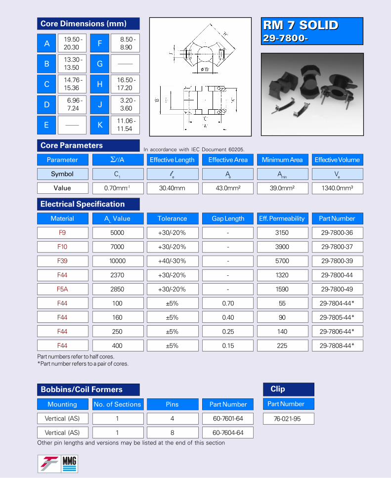
RM 7 SOLID29-7800-RM 7 SOLID29-7800-
Mounting No. of Sections Pins Part Number
Vertical (AS) 1 4 60-7601-64
Vertical (AS) 1 8 60-7604-64
Parameter Σl /A Effective Length Effective Area Minimum Area Effective Volume
Symbol C1 le Ae Amin Ve
Value 0.70mm-1 30.40mm 43.0mm² 39.0mm² 1340.0mm³
Core ParametersIn accordance with IEC Document 60205.
Other pin lengths and versions may be listed at the end of this section
Electrical Specification
Bobbins/Coil Formers
Part numbers refer to half cores.*Part number refers to a pair of cores.
F44 100 ±5% 0.70 55 29-7804-44*
F44 160 ±5% 0.40 90 29-7805-44*
F44 250 ±5% 0.25 140 29-7806-44*
F44 400 ±5% 0.15 225 29-7808-44*
Material AL Value Tolerance Gap Length Eff. Permeability Part Number
F9 5000 +30/-20% - 3150 29-7800-36
F10 7000 +30/-20% - 3900 29-7800-37
F39 10000 +40/-30% - 5700 29-7800-39
F44 2370 +30/-20% - 1320 29-7800-44
F5A 2850 +30/-20% - 1590 29-7800-49
76-021-95
Clip
Part Number
Core Dimensions (mm)
A
B
C
D
E
F
G
H
J
K
19.50 -20.30
13.30 -13.50
14.76 -15.36
6.96 -7.24
8.50 -8.90
16.50 -17.20
3.20 -3.60
11.06 -11.54

RM 829-790-RM 829-790-
Part numbers refer to half cores.Non adjustable type may be available on request.
Parameter Σl /A Effective Length Effective Area Minimum Area Effective Volume
Symbol C1 le Ae Amin Ve
Value 0.68mm-1 35.50mm 52.00mm² - 1850.00mm³
Core Parameters
Electrical Specification
In accordance with IEC Document 60205.
Bobbins/Coil Formers Adjusters
Other pin lengths or variation may be listed at the end of this section
Clip
Mounting No. of Sections Pins Part Number
Vertical (Z) 1 8 60-792-64
Vertical (AS) 1 12 60-793-64
AL Value
63/100/160
250/400
630
Part Number
64-4834-66
64-4833-66
64-4835-66
76-022-95
Material AL Value Tolerance Gap Length Eff. Permeability Part Number
P11 2500 +30/-20% - 1350 29-790-41
F58 1170 +30/-20% - 630 29-790-58
F58 63 ±3% 1.40 34 29-7903-58*
F58 100 ±3% 0.80 54 29-7904-58*
P11 100 ±3% 0.86 54 29-7904-41*
P11 160 ±3% 0.40 86 29-7905-41*
P11 250 ±3% 0.23 135 29-7906-41*
P11 315 ±3% 0.18 170 29-7907-41*
P11 400 ±3% 0.13 216 29-7908-41*
P11 630 ±3% 0.08 341 29-7909-41**Part number refers to a pair of cores fitted with a nut foradjustable inductance assemblies.
Core Dimensions (mm)
A
B
C
D
E
22.30 -23.20
16.30 -16.50
17.00 -17.70
8.25 -8.55
4.40 -4.60
10.80 -11.20
10.50 -11.40
18.90 -19.70
4.30 -5.10
14.06 -14.54
F
G
H
J
K

RM 8 SOLID29-810-RM 8 SOLID29-810-
Mounting No. of Sections Pins Part Number
Vertical (Z) 1 8 60-792-64
Vertical (AS) 1 12 60-793-64
Parameter Σl /A Effective Length Effective Area Minimum Area Effective Volume
Symbol C1 le Ae Amin Ve
Value 0.59mm-1 38.0mm 64.0mm² 55.0mm² 2430.0mm³
Core ParametersIn accordance with IEC Document 60205.
Other pin lengths and versions may be listed at the end of this section
Electrical Specification
Bobbins/Coil Formers
Part numbers refer to half cores.
F5A 4000 +30/-20% - 1880 29-810-49
F44 100 ±5% 0.70 47 29-811-44*
F44 160 ±5% 0.40 75 29-812-44*
F44 250 ±5% 0.25 117 29-813-44*
F44 315 ±5% 0.15 188 29-814-44*
Material AL Value Tolerance Gap Length Eff. Permeability Part Number
F9 5700 +30/-20% - 2675 29-810-36
F10 8375 +30/-20% - 3930 29-810-37
F39 12500 +40/-30% - 5870 29-810-39
F44 2905 +30/-20% - 1365 29-810-44
F45 3300 +30/-20% - 1550 29-810-45
76-022-95
Clip
Part Number
Core Dimensions (mm)
A
B
C
D
E
22.30 -23.20
16.30 -16.50
17.00 -17.70
8.25 -8.55
F
G
H
J
K
10.80 -11.20
10.50 -11.00
18.90 -19.70
4.30 -5.10
14.06 -14.54
*Part number refers to a pair of cores.
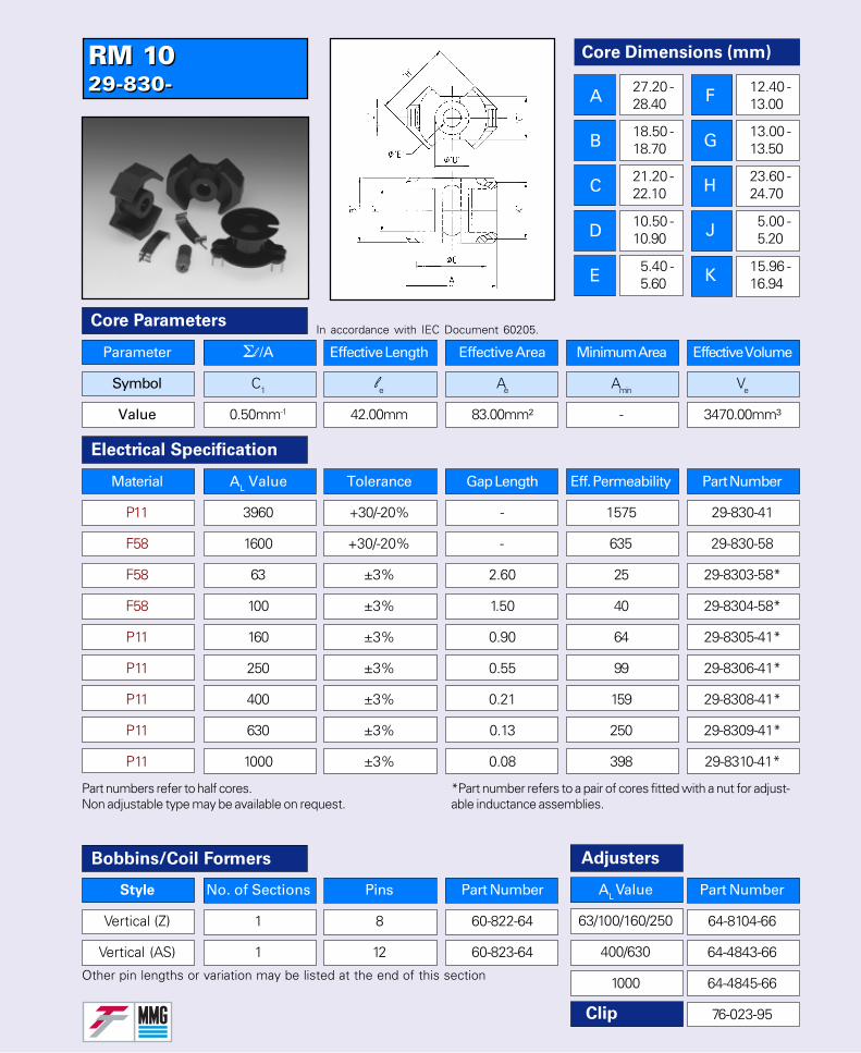
RM 1029-830-RM 1029-830-
Part numbers refer to half cores.Non adjustable type may be available on request.
Parameter Σl /A Effective Length Effective Area Minimum Area Effective Volume
Symbol C1 le Ae Amin Ve
Value 0.50mm-1 42.00mm 83.00mm² - 3470.00mm³
Core Parameters
Electrical Specification
In accordance with IEC Document 60205.
Bobbins/Coil Formers Adjusters
Other pin lengths or variation may be listed at the end of this section
Clip
Style No. of Sections Pins Part Number
Vertical (Z) 1 8 60-822-64
Vertical (AS) 1 12 60-823-64
AL Value
63/100/160/250
400/630
1000
Part Number
64-8104-66
64-4843-66
64-4845-66
76-023-95
Material AL Value Tolerance Gap Length Eff. Permeability Part Number
P11 3960 +30/-20% - 1575 29-830-41
F58 1600 +30/-20% - 635 29-830-58
F58 63 ±3% 2.60 25 29-8303-58*
F58 100 ±3% 1.50 40 29-8304-58*
P11 160 ±3% 0.90 64 29-8305-41*
P11 250 ±3% 0.55 99 29-8306-41*
P11 400 ±3% 0.21 159 29-8308-41*
P11 630 ±3% 0.13 250 29-8309-41*
P11 1000 ±3% 0.08 398 29-8310-41*
*Part number refers to a pair of cores fitted with a nut for adjust-able inductance assemblies.
Core Dimensions (mm)
A
B
C
D
E
27.20 -28.40
18.50 -18.70
21.20 -22.10
10.50 -10.90
5.40 -5.60
12.40 -13.00
13.00 -13.50
23.60 -24.70
5.00 -5.20
15.96 -16.94
F
G
H
J
K
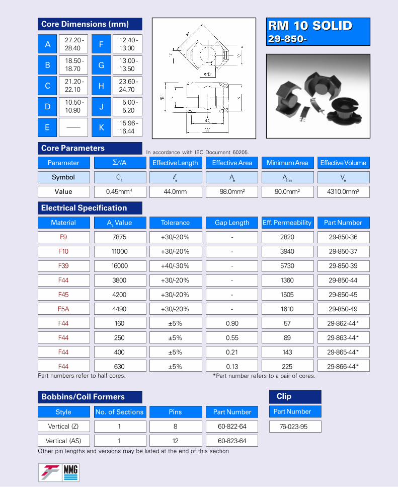
RM 10 SOLID29-850-RM 10 SOLID29-850-
Style No. of Sections Pins Part Number
Vertical (Z) 1 8 60-822-64
Vertical (AS) 1 12 60-823-64
Parameter Σl /A Effective Length Effective Area Minimum Area Effective Volume
Symbol C1 le Ae Amin Ve
Value 0.45mm-1 44.0mm 98.0mm² 90.0mm² 4310.0mm³
Core ParametersIn accordance with IEC Document 60205.
Other pin lengths and versions may be listed at the end of this section
Electrical Specification
Bobbins/Coil Formers
Part numbers refer to half cores.
F5A 4490 +30/-20% - 1610 29-850-49
F44 160 ±5% 0.90 57 29-862-44*
F44 250 ±5% 0.55 89 29-863-44*
F44 400 ±5% 0.21 143 29-865-44*
F44 630 ±5% 0.13 225 29-866-44*
Material AL Value Tolerance Gap Length Eff. Permeability Part Number
F9 7875 +30/-20% - 2820 29-850-36
F10 11000 +30/-20% - 3940 29-850-37
F39 16000 +40/-30% - 5730 29-850-39
F44 3800 +30/-20% - 1360 29-850-44
F45 4200 +30/-20% - 1505 29-850-45
76-023-95
Clip
Part Number
Core Dimensions (mm)
A
B
C
D
E
27.20 -28.40
18.50 -18.70
21.20 -22.10
10.50 -10.90
12.40 -13.00
13.00 -13.50
23.60 -24.70
5.00 -5.20
15.96 -16.44
F
G
H
J
K
*Part number refers to a pair of cores.
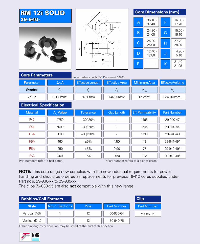
RM 12i SOLID29-940-RM 12i SOLID29-940-
76-085-95
Parameter Σl /A Effective Length Effective Area Minimum Area Effective Volume
Symbol C1 le Ae Amin Ve
Value 0.388mm-1 56.60mm 146.00mm² 125mm2 8340.00mm³
Core Parameters
Electrical Specification
In accordance with IEC Document 60205.
Bobbins/Coil Formers
Other pin lengths or variation may be listed at the end of this section
Style No. of Sections Pins Part Number
Vertical (AS) 1 12 60-930-64
Vertical (DIL) 1 12 60-940-76
Material AL Value Tolerance Gap Length Eff. Permeability Part Number
F47 4750 +30/-20% - 1465 29-940-47
F44 5000 +30/-20% - 1545 29-940-44
F5A 5800 +30/-20% - 1790 29-940-49
F5A 160 ±5% 1.50 49 29-941-49*
F5A 250 ±5% 0.90 77 29-942-49*
F5A 400 ±5% 0.50 123 29-943-49*
Core Dimensions (mm)
A
B
C
D
E
36.10 -37.40
24.30 -24.60
25.00 -26.00
12.40 -12.80
16.80 -17.70
15.60 -16.10
27.70 -28.80
4.90 -5.10
21.40 -21.98
Part numbers refer to half cores. *Part number refers to a pair of cores.
NOTE: This core range now complies with the new industrial requirements for powerhandling and should be ordered as replacements for previous RM12 cores supplied underPart no’s. 29-930-xx to 29-939-xx.The clips 76-030-95 are also not compatible with this new range.
Clip
Part Number
F
G
H
J
K
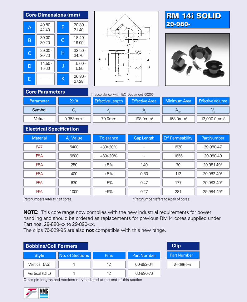
RM 14i SOLID29-980-RM 14i SOLID29-980-
Style No. of Sections Pins Part Number
Vertical (AS) 1 12 60-882-64
Vertical (DIL) 1 12 60-990-76
Parameter Σl /A Effective Length Effective Area Minimum Area Effective Volume
Symbol C1 le Ae Amin Ve
Value 0.353mm-1 70.0mm 198.0mm² 168.0mm² 13,900.0mm³
Core ParametersIn accordance with IEC Document 60205.
Other pin lengths and versions may be listed at the end of this section
Electrical Specification
Bobbins/Coil Formers
Part numbers refer to half cores.
F5A 1000 ±5% 0.27 281 29-984-49*
Material AL Value Tolerance Gap Length Eff. Permeability Part Number
F47 5400 +30/-20% - 1520 29-980-47
F5A 6600 +30/-20% - 1855 29-980-49
F5A 250 ±5% 1.40 70 29-981-49*
F5A 400 ±5% 0.80 112 29-982-49*
F5A 630 ±5% 0.47 177 29-983-49*
76-086-95
Clip
Part Number
*Part number refers to a pair of cores.
Core Dimensions (mm)
A
B
C
D
E
40.80 -42.40
30.00 -30.20
29.00 -30.20
14.50 -15.00
20.80 -21.40
18.40 -19.00
33.50 -34.70
5.60 -5.80
26.80 -27.28
NOTE: This core range now complies with the new industrial requirements for powerhandling and should be ordered as replacements for previous RM14 cores supplied underPart nos. 29-880-xx to 29-890-xx.The clips 76-029-95 are also not compatible with this new range.
F
G
H
J
K
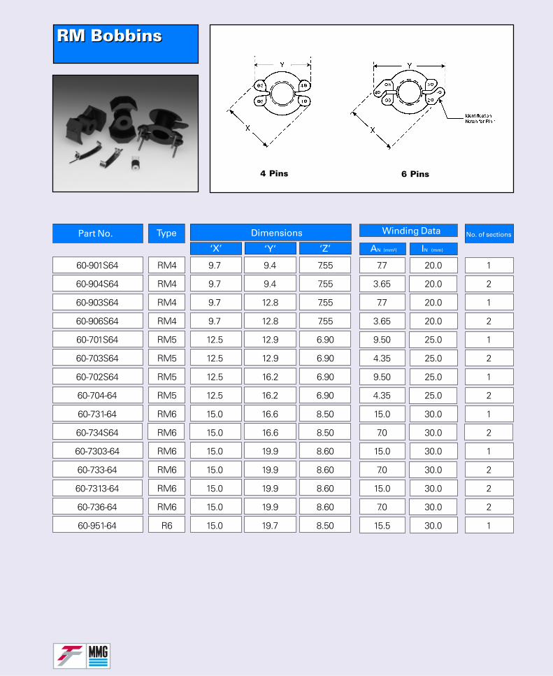
RM BobbinsRM Bobbins
No. of sectionsPart No. Type Dimensions
‘X’ ‘Y’ ‘Z’
Winding Data
AN (mm²) IN (mm)
4 Pins 6 Pins
60-901S64 RM4 9.7 9.4 7.55 7.7 20.0 1
60-904S64 RM4 9.7 9.4 7.55 3.65 20.0 2
60-903S64 RM4 9.7 12.8 7.55 7.7 20.0 1
60-906S64 RM4 9.7 12.8 7.55 3.65 20.0 2
60-701S64 RM5 12.5 12.9 6.90 9.50 25.0 1
60-703S64 RM5 12.5 12.9 6.90 4.35 25.0 2
60-702S64 RM5 12.5 16.2 6.90 9.50 25.0 1
60-704-64 RM5 12.5 16.2 6.90 4.35 25.0 2
60-731-64 RM6 15.0 16.6 8.50 15.0 30.0 1
60-734S64 RM6 15.0 16.6 8.50 7.0 30.0 2
60-7303-64 RM6 15.0 19.9 8.60 15.0 30.0 1
60-733-64 RM6 15.0 19.9 8.60 7.0 30.0 2
60-7313-64 RM6 15.0 19.9 8.60 15.0 30.0 2
60-736-64 RM6 15.0 19.9 8.60 7.0 30.0 2
60-951-64 R6 15.0 19.7 8.50 15.5 30.0 1
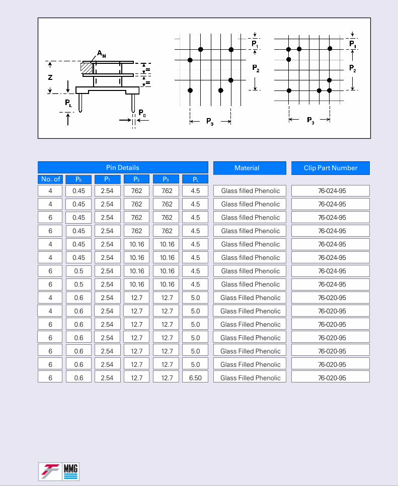
Material
No. of
Clip Part Number
P1 P2 P3 PL
Pin Details
P0
4 0.45 2.54 7.62 7.62 4.5 Glass filled Phenolic 76-024-95
4 0.45 2.54 7.62 7.62 4.5 Glass filled Phenolic 76-024-95
6 0.45 2.54 7.62 7.62 4.5 Glass filled Phenolic 76-024-95
6 0.45 2.54 7.62 7.62 4.5 Glass filled Phenolic 76-024-95
4 0.45 2.54 10.16 10.16 4.5 Glass filled Phenolic 76-024-95
4 0.45 2.54 10.16 10.16 4.5 Glass filled Phenolic 76-024-95
6 0.5 2.54 10.16 10.16 4.5 Glass filled Phenolic 76-024-95
6 0.5 2.54 10.16 10.16 4.5 Glass filled Phenolic 76-024-95
4 0.6 2.54 12.7 12.7 5.0 Glass Filled Phenolic 76-020-95
4 0.6 2.54 12.7 12.7 5.0 Glass Filled Phenolic 76-020-95
6 0.6 2.54 12.7 12.7 5.0 Glass Filled Phenolic 76-020-95
6 0.6 2.54 12.7 12.7 5.0 Glass Filled Phenolic 76-020-95
6 0.6 2.54 12.7 12.7 5.0 Glass Filled Phenolic 76-020-95
6 0.6 2.54 12.7 12.7 5.0 Glass Filled Phenolic 76-020-95
6 0.6 2.54 12.7 12.7 6.50 Glass Filled Phenolic 76-020-95
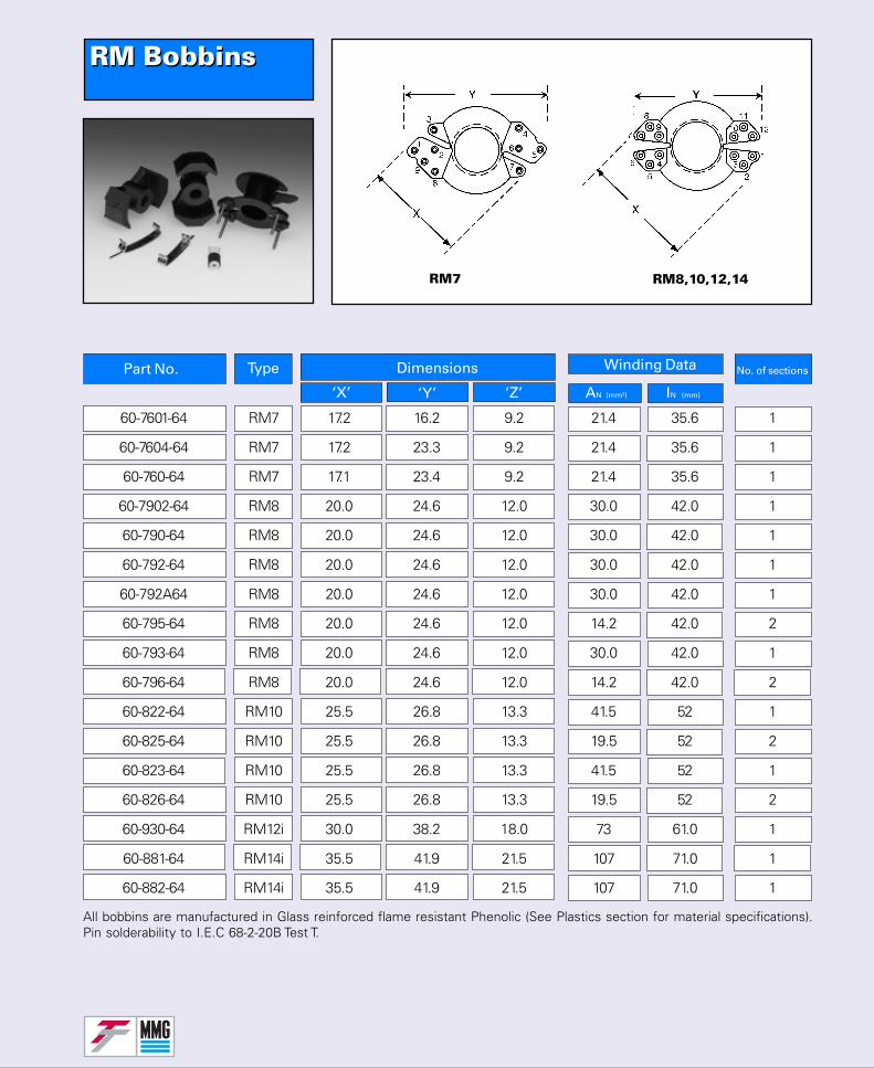
No. of sectionsPart No. Type Dimensions
‘X’ ‘Y’ ‘Z’
Winding Data
AN (mm²) IN (mm)
RM BobbinsRM Bobbins
60-7601-64 RM7 17.2 16.2 9.2 21.4 35.6 1
60-7604-64 RM7 17.2 23.3 9.2 21.4 35.6 1
60-760-64 RM7 17.1 23.4 9.2 21.4 35.6 1
60-7902-64 RM8 20.0 24.6 12.0 30.0 42.0 1
60-790-64 RM8 20.0 24.6 12.0 30.0 42.0 1
60-792-64 RM8 20.0 24.6 12.0 30.0 42.0 1
60-792A64 RM8 20.0 24.6 12.0 30.0 42.0 1
60-795-64 RM8 20.0 24.6 12.0 14.2 42.0 2
60-793-64 RM8 20.0 24.6 12.0 30.0 42.0 1
60-796-64 RM8 20.0 24.6 12.0 14.2 42.0 2
60-822-64 RM10 25.5 26.8 13.3 41.5 52 1
60-825-64 RM10 25.5 26.8 13.3 19.5 52 2
60-823-64 RM10 25.5 26.8 13.3 41.5 52 1
60-826-64 RM10 25.5 26.8 13.3 19.5 52 2
60-930-64 RM12i 30.0 38.2 18.0 73 61.0 1
60-881-64 RM14i 35.5 41.9 21.5 107 71.0 1
60-882-64 RM14i 35.5 41.9 21.5 107 71.0 1
RM7 RM8,10,12,14
All bobbins are manufactured in Glass reinforced flame resistant Phenolic (See Plastics section for material specifications).Pin solderability to I.E.C 68-2-20B Test T.
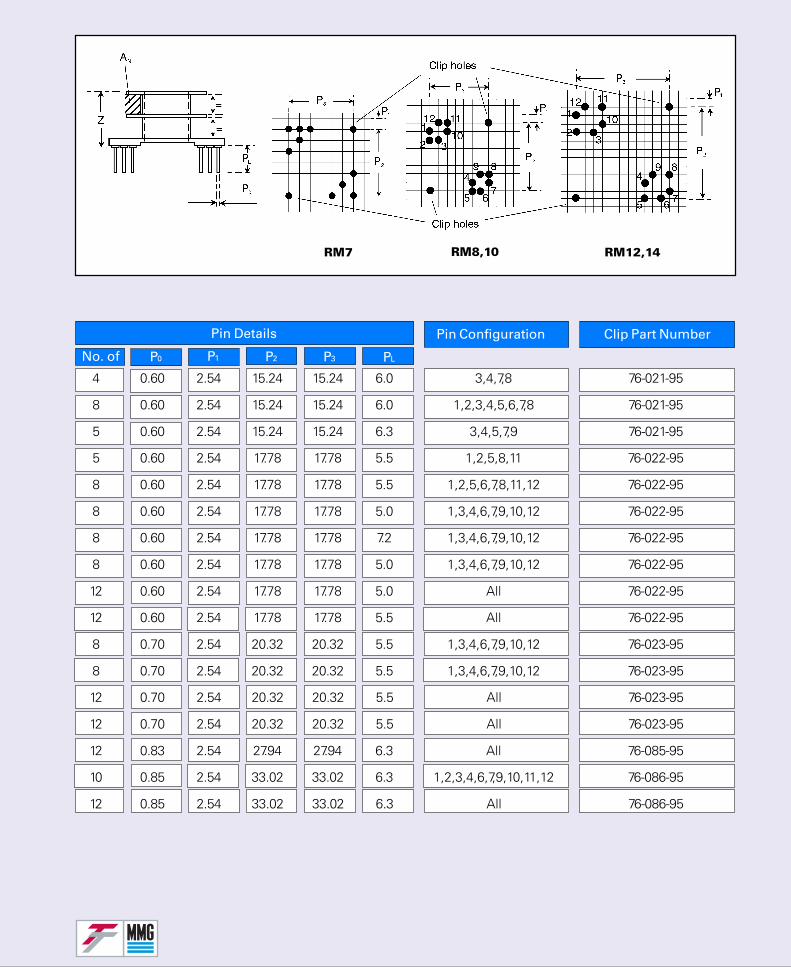
Pin Configuration
No. of
Clip Part Number
P1 P2 P3 PL
Pin Details
P0
RM8,10 RM12,14RM7
4 0.60 2.54 15.24 15.24 6.0 3,4,7,8 76-021-95
8 0.60 2.54 15.24 15.24 6.0 1,2,3,4,5,6,7,8 76-021-95
5 0.60 2.54 15.24 15.24 6.3 3,4,5,7,9 76-021-95
5 0.60 2.54 17.78 17.78 5.5 1,2,5,8,11 76-022-95
8 0.60 2.54 17.78 17.78 5.5 1,2,5,6,7,8,11,12 76-022-95
8 0.60 2.54 17.78 17.78 5.0 1,3,4,6,7,9,10,12 76-022-95
8 0.60 2.54 17.78 17.78 7.2 1,3,4,6,7,9,10,12 76-022-95
8 0.60 2.54 17.78 17.78 5.0 1,3,4,6,7,9,10,12 76-022-95
12 0.60 2.54 17.78 17.78 5.0 All 76-022-95
12 0.60 2.54 17.78 17.78 5.5 All 76-022-95
8 0.70 2.54 20.32 20.32 5.5 1,3,4,6,7,9,10,12 76-023-95
8 0.70 2.54 20.32 20.32 5.5 1,3,4,6,7,9,10,12 76-023-95
12 0.70 2.54 20.32 20.32 5.5 All 76-023-95
12 0.70 2.54 20.32 20.32 5.5 All 76-023-95
12 0.83 2.54 27.94 27.94 6.3 All 76-085-95
10 0.85 2.54 33.02 33.02 6.3 1,2,3,4,6,7,9,10,11,12 76-086-95
12 0.85 2.54 33.02 33.02 6.3 All 76-086-95
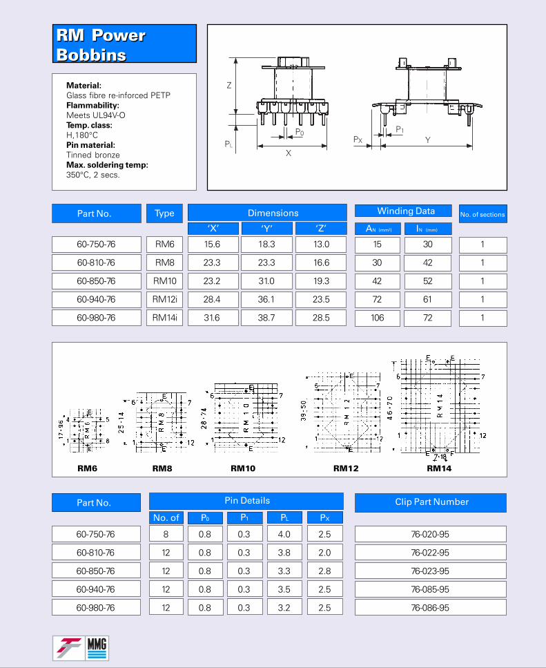
RM PowerBobbinsRM PowerBobbins
No. of sectionsPart No. Type Dimensions
‘X’ ‘Y’ ‘Z’
Winding Data
AN (mm²) IN (mm)
Part No.
P1 PL PX
Pin Details
P0No. of
Clip Part Number
60-750-76 RM6 15.6 18.3 13.0 15 30 1
60-810-76 RM8 23.3 23.3 16.6 30 42 1
60-850-76 RM10 23.2 31.0 19.3 42 52 1
60-940-76 RM12i 28.4 36.1 23.5 72 61 1
60-980-76 RM14i 31.6 38.7 28.5 106 72 1
Material:
Glass fibre re-inforced PETPFlammability:
Meets UL94V-OTemp. class:
H,180°CPin material:
Tinned bronzeMax. soldering temp:
350°C, 2 secs.
RM6 RM10RM8 RM12 RM14
60-750-76 8 0.8 0.3 4.0 2.5 76-020-95
60-810-76 12 0.8 0.3 3.8 2.0 76-022-95
60-850-76 12 0.8 0.3 3.3 2.8 76-023-95
60-940-76 12 0.8 0.3 3.5 2.5 76-085-95
60-980-76 12 0.8 0.3 3.2 2.5 76-086-95
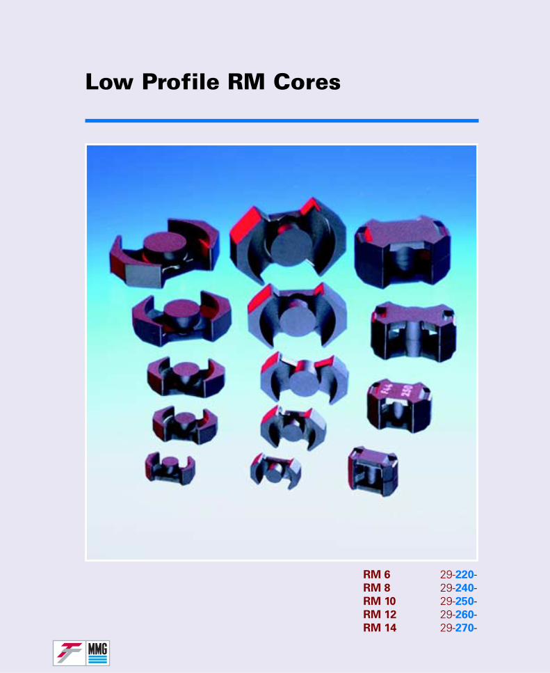
Low Profile RM Cores
RM 6 29-220-RM 8 29-240-RM 10 29-250-RM 12 29-260-RM 14 29-270-
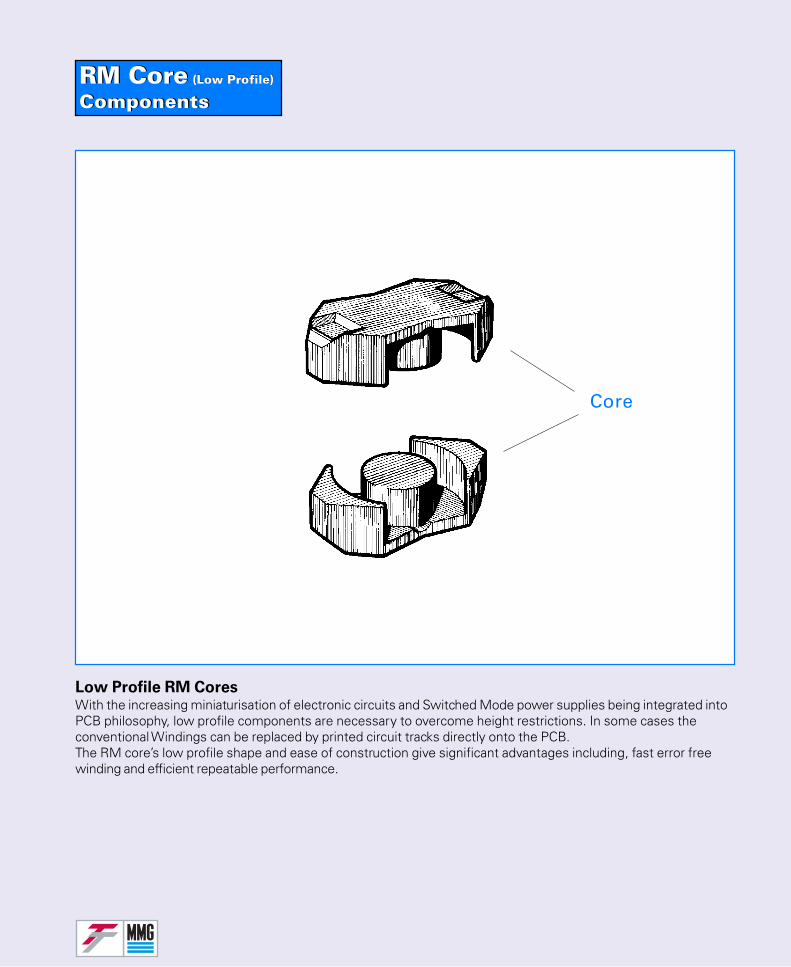
RM Core (Low Profile)
ComponentsRM Core (Low Profile)
Components
Low Profile RM CoresWith the increasing miniaturisation of electronic circuits and Switched Mode power supplies being integrated intoPCB philosophy, low profile components are necessary to overcome height restrictions. In some cases theconventional Windings can be replaced by printed circuit tracks directly onto the PCB.The RM core’s low profile shape and ease of construction give significant advantages including, fast error freewinding and efficient repeatable performance.
Core
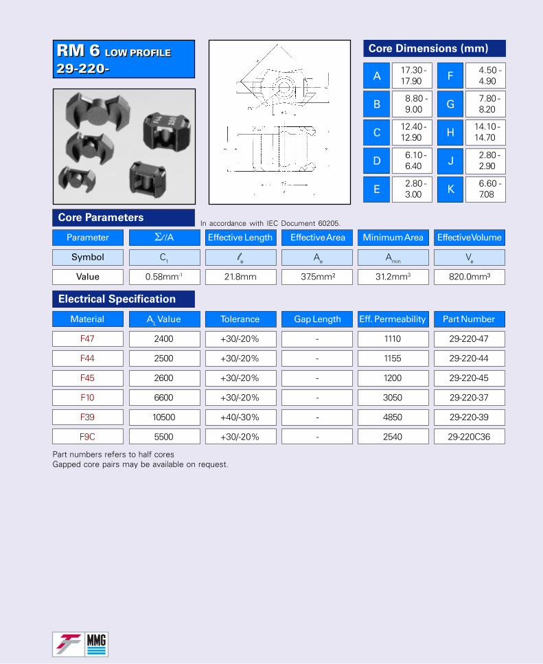
RM 6 LOW PROFILE
29-220-RM 6 LOW PROFILE
29-220-
Part numbers refers to half coresGapped core pairs may be available on request.
Parameter Σl /A Effective Length Effective Area Minimum Area Effective Volume
Symbol C1 le Ae Amin Ve
Value 0.58mm-1 21.8mm 37.5mm² 31.2mm3 820.0mm³
Core Parameters
Electrical Specification
In accordance with IEC Document 60205.
Core Dimensions (mm)
A
B
C
D
E
F
G
H
J
K
17.30 -17.90
8.80 -9.00
12.40 -12.90
6.10 -6.40
2.80 -3.00
4.50 -4.90
7.80 -8.20
14.10 -14.70
2.80 -2.90
6.60 -7.08
Material AL Value Tolerance Gap Length Eff. Permeability Part Number
F47 2400 +30/-20% - 1110 29-220-47
F44 2500 +30/-20% - 1155 29-220-44
F45 2600 +30/-20% - 1200 29-220-45
F10 6600 +30/-20% - 3050 29-220-37
F39 10500 +40/-30% - 4850 29-220-39
F9C 5500 +30/-20% - 2540 29-220C36
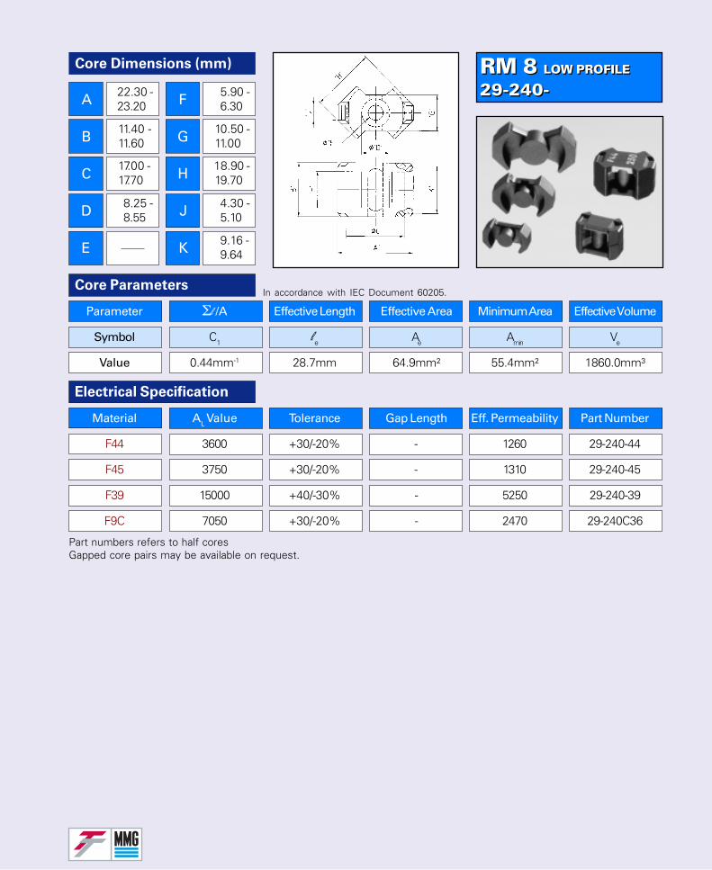
RM 8 LOW PROFILE
29-240-RM 8 LOW PROFILE
29-240-
Parameter Σl /A Effective Length Effective Area Minimum Area Effective Volume
Symbol C1 le Ae Amin Ve
Value 0.44mm-1 28.7mm 64.9mm² 55.4mm² 1860.0mm³
Core ParametersIn accordance with IEC Document 60205.
Electrical Specification
Core Dimensions (mm)
A
B
C
D
E
F
G
H
J
K
22.30 -23.20
11.40 -11.60
17.00 -17.70
8.25 -8.55
5.90 -6.30
10.50 -11.00
18.90 -19.70
4.30 -5.10
9.16 -9.64
Part numbers refers to half coresGapped core pairs may be available on request.
Material AL Value Tolerance Gap Length Eff. Permeability Part Number
F44 3600 +30/-20% - 1260 29-240-44
F45 3750 +30/-20% - 1310 29-240-45
F39 15000 +40/-30% - 5250 29-240-39
F9C 7050 +30/-20% - 2470 29-240C36
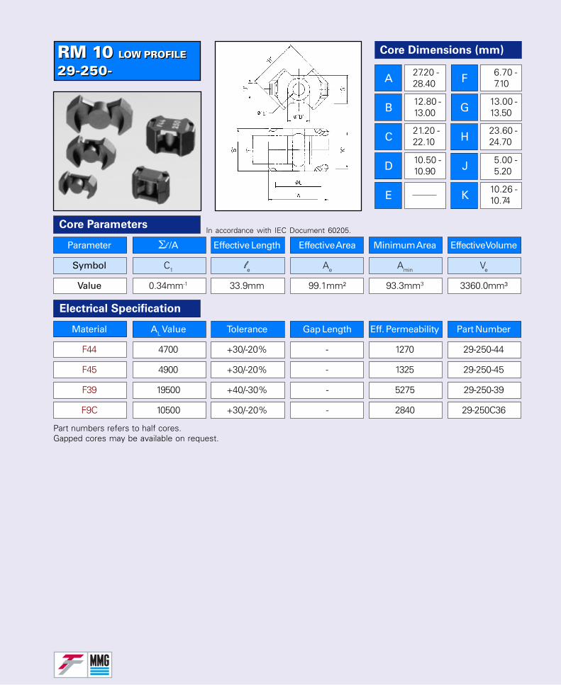
RM 10 LOW PROFILE
29-250-RM 10 LOW PROFILE
29-250-
Part numbers refers to half cores.Gapped cores may be available on request.
Parameter Σl /A Effective Length Effective Area Minimum Area Effective Volume
Symbol C1 le Ae Amin Ve
Value 0.34mm-1 33.9mm 99.1mm² 93.3mm3 3360.0mm³
Core Parameters
Electrical Specification
In accordance with IEC Document 60205.
Core Dimensions (mm)
A
B
C
D
E
F
G
H
J
K
27.20 -28.40
12.80 -13.00
21.20 -22.10
10.50 -10.90
6.70 -7.10
13.00 -13.50
23.60 -24.70
5.00 -5.20
10.26 -10.74
Material AL Value Tolerance Gap Length Eff. Permeability Part Number
F44 4700 +30/-20% - 1270 29-250-44
F45 4900 +30/-20% - 1325 29-250-45
F39 19500 +40/-30% - 5275 29-250-39
F9C 10500 +30/-20% - 2840 29-250C36
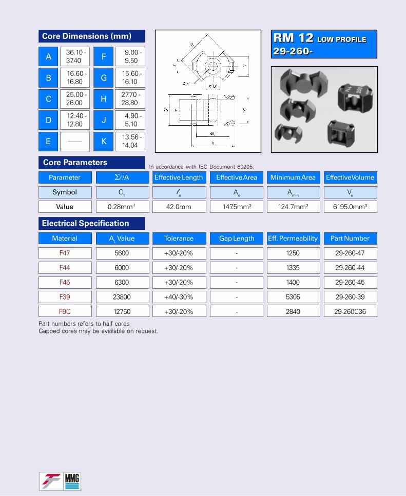
RM 12 LOW PROFILE
29-260-RM 12 LOW PROFILE
29-260-
Parameter Σl /A Effective Length Effective Area Minimum Area Effective Volume
Symbol C1 le Ae Amin Ve
Value 0.28mm-1 42.0mm 147.5mm² 124.7mm² 6195.0mm³
Core ParametersIn accordance with IEC Document 60205.
Electrical Specification
Core Dimensions (mm)
A
B
C
D
E
F
G
H
J
K
36.10 -37.40
16.60 -16.80
25.00 -26.00
12.40 -12.80
9.00 -9.50
15.60 -16.10
27.70 -28.80
4.90 -5.10
13.56 -14.04
Part numbers refers to half coresGapped cores may be available on request.
Material AL Value Tolerance Gap Length Eff. Permeability Part Number
F47 5600 +30/-20% - 1250 29-260-47
F44 6000 +30/-20% - 1335 29-260-44
F45 6300 +30/-20% - 1400 29-260-45
F39 23800 +40/-30% - 5305 29-260-39
F9C 12750 +30/-20% - 2840 29-260C36
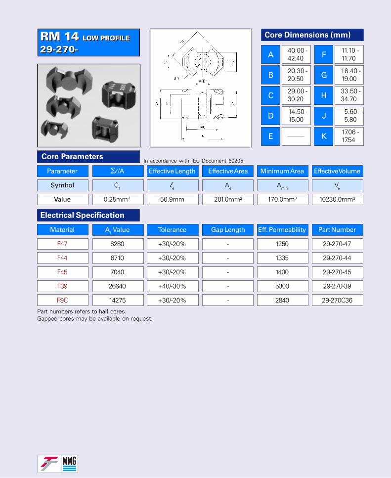
RM 14 LOW PROFILE
29-270-RM 14 LOW PROFILE
29-270-
Part numbers refers to half cores.Gapped cores may be available on request.
Parameter Σl /A Effective Length Effective Area Minimum Area Effective Volume
Symbol C1 le Ae Amin Ve
Value 0.25mm-1 50.9mm 201.0mm² 170.0mm3 10230.0mm³
Core Parameters
Electrical Specification
In accordance with IEC Document 60205.
Core Dimensions (mm)
A
B
C
D
E
F
G
H
J
K
40.00 -42.40
20.30 -20.50
29.00 -30.20
14.50 -15.00
11.10 -11.70
18.40 -19.00
33.50 -34.70
5.60 -5.80
17.06 -17.54
Material AL Value Tolerance Gap Length Eff. Permeability Part Number
F47 6280 +30/-20% - 1250 29-270-47
F44 6710 +30/-20% - 1335 29-270-44
F45 7040 +30/-20% - 1400 29-270-45
F39 26640 +40/-30% - 5300 29-270-39
F9C 14275 +30/-20% - 2840 29-270C36
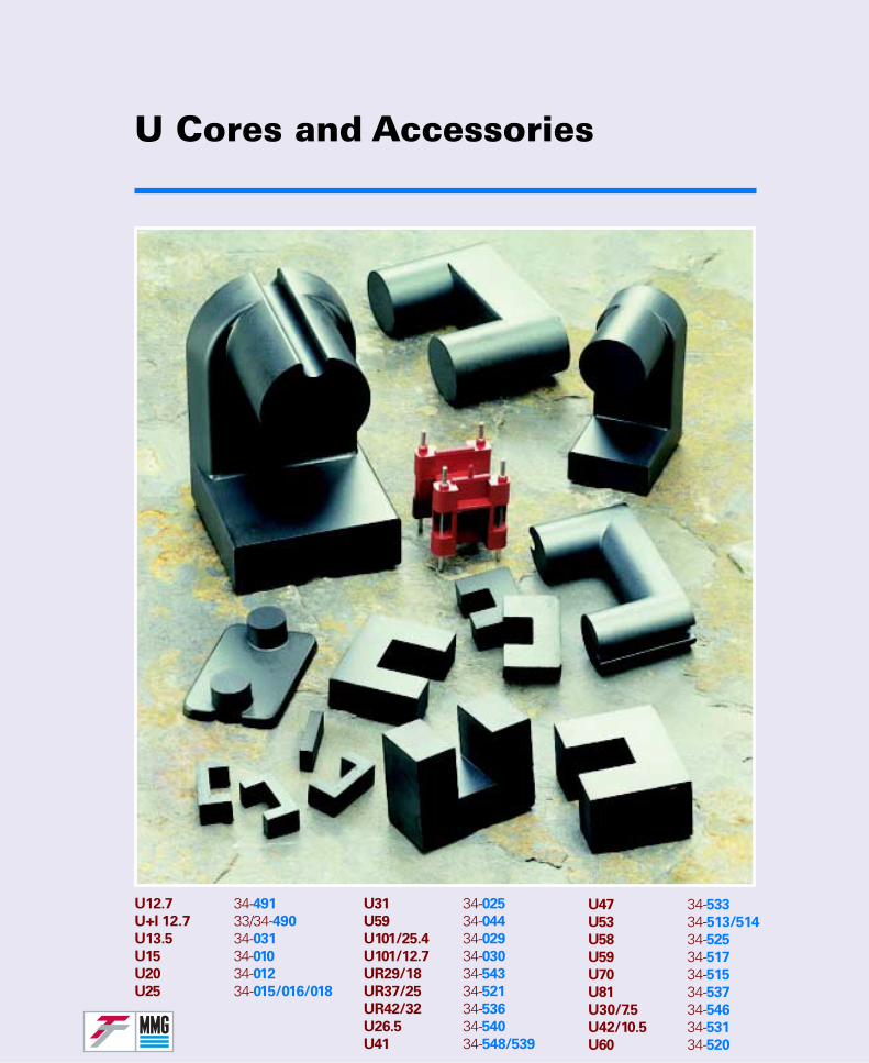
U Cores and Accessories
U12.7 34-491
U+I 12.7 33/34-490
U13.5 34-031
U15 34-010
U20 34-012
U25 34-015/016/018
U31 34-025
U59 34-044
U101/25.4 34-029
U101/12.7 34-030
UR29/18 34-543
UR37/25 34-521
UR42/32 34-536
U26.5 34-540
U41 34-548/539
U47 34-533
U53 34-513/514
U58 34-525
U59 34-517
U70 34-515
U81 34-537
U30/7.5 34-546
U42/10.5 34-531
U60 34-520
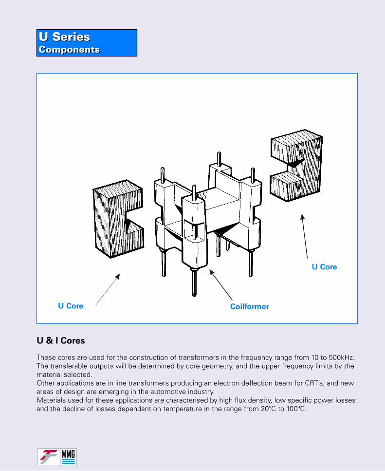
U SeriesComponentsU SeriesComponents
U & I Cores
U Core
CoilformerU Core
These cores are used for the construction of transformers in the frequency range from 10 to 500kHz.The transferable outputs will be determined by core geometry, and the upper frequency limits by thematerial selected.Other applications are in line transformers producing an electron deflection beam for CRT’s, and newareas of design are emerging in the automotive industry.Materials used for these applications are characterised by high flux density, low specific power lossesand the decline of losses dependant on temperature in the range from 20ºC to 100ºC.
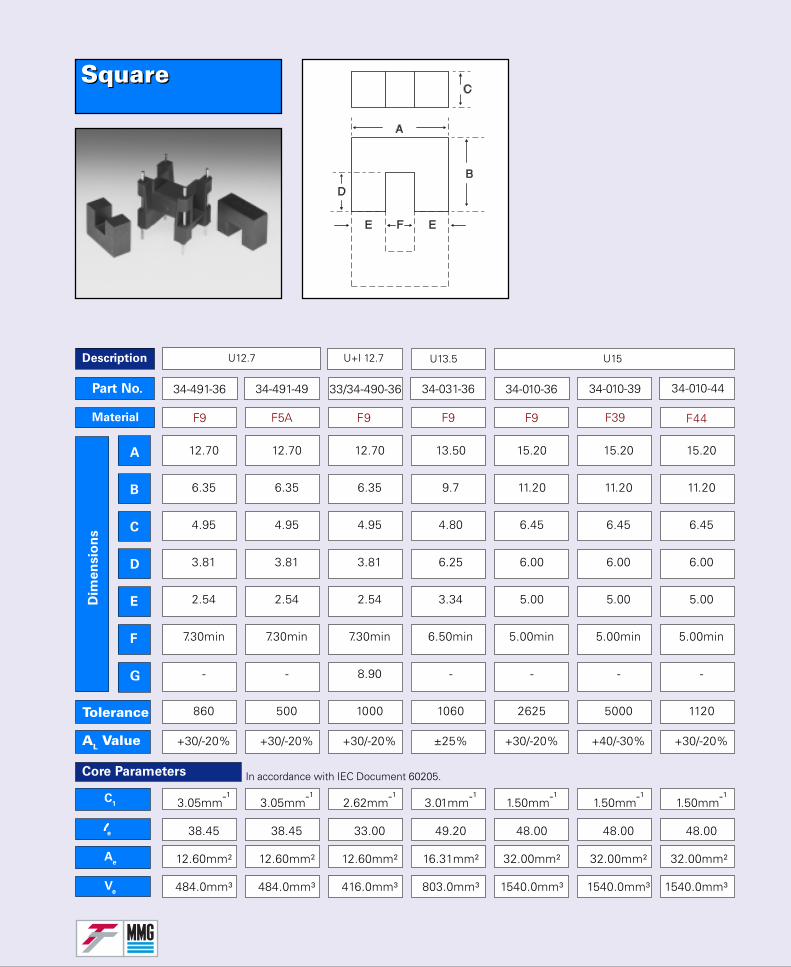
34-491-36
F9
34-491-49
F5A
Part No.
Material
Dim
en
sio
ns
Tolerance
C1
llllle
Ae
Ve
A
B
C
D
E
F
G
U12.7
34-010-39
F39
U13.5 U15U+I 12.7
Core Parameters
SquareSquare
AL Value
33/34-490-36
F9 F44
34-031-36
F9
34-010-36
F9
34-010-44
12.70 12.70 12.70 13.50 15.20 15.20 15.20
6.35 6.35 6.35 9.7 11.20 11.20 11.20
4.95 4.95 4.95 4.80 6.45 6.45 6.45
3.81 3.81 3.81 6.25 6.00 6.00 6.00
2.54 2.54 2.54 3.34 5.00 5.00 5.00
7.30min 7.30min 7.30min 6.50min 5.00min 5.00min 5.00min
- - 8.90 - - - -
860 500 1000 1060 2625 5000 1120
+30/-20% +30/-20% +30/-20% ±25% +30/-20% +40/-30% +30/-20%
3.05mm-¹ 3.05mm-¹ 2.62mm-¹ 3.01mm-¹ 1.50mm-¹ 1.50mm-¹ 1.50mm-¹
38.45 38.45 33.00 49.20 48.00 48.00 48.00
12.60mm² 12.60mm² 12.60mm² 16.31mm² 32.00mm² 32.00mm² 32.00mm²
484.0mm³ 484.0mm³ 416.0mm³ 803.0mm³ 1540.0mm³ 1540.0mm³ 1540.0mm³
Description
In accordance with IEC Document 60205.
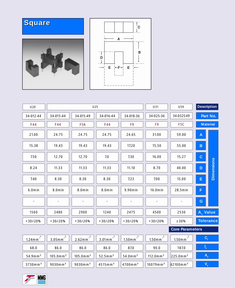
Part No.
Material
Dim
en
sio
ns
AL Value
Tolerance
C1
llllle
Ae
Ve
A
B
C
D
E
F
G
Core Parameters
34-015-49
F5A
U20
34-018-36
F9
34-025-36
F9
34-032S49
F5C
U59U25 U31
34-012-44
F44
34-015-44
F44
34-016-44
F44
21.00 24.75 24.75 24.75 24.65 31.00 59.00
15.38 19.43 19.43 19.43 17.20 15.50 55.00
7.50 12.70 12.70 7.0 7.30 16.00 15.27
8.24 11.33 11.33 11.33 11.10 8.70 40.00
7.40 8.30 8.30 8.30 7.23 7.00 15.00
6.0min 8.0min 8.0min 8.0min 9.90min 16.0min 28.5min
- - - - - - -
1560 2480 2900 1240 2475 4500 2530
+30/-20% +30/-20% +30/-20% +30/-20% +30/-20% +30/-20% ±30%
1.24mm-¹ 3.05mm-¹ 2.62mm-¹ 3.01mm-¹ 1.50mm-¹ 1.50mm-¹ 1.50mm-¹
68.0 86.0 86.0 86.0 87.0 90.0 187.0
54.9mm² 105.0mm² 105.0mm² 52.5mm² 54.0mm² 112.0mm² 225.0mm²
3730mm³ 9030mm³ 9030mm³ 4515mm³ 4700mm³ 10079mm³ 42100mm³
Description
SquareSquare
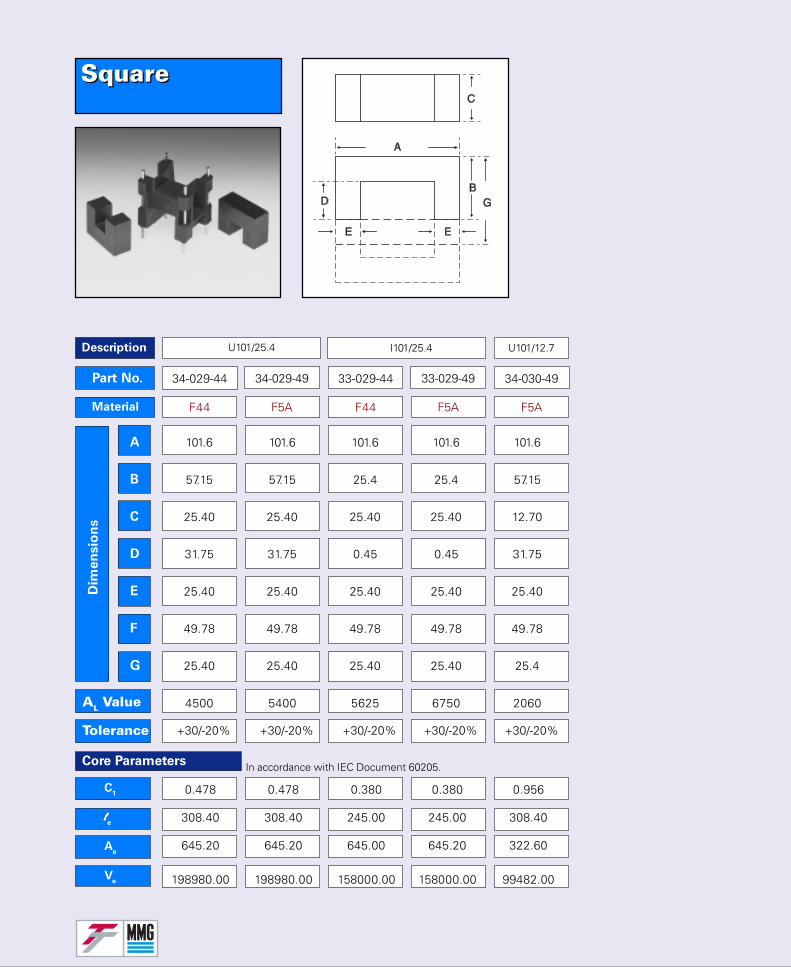
SquareSquare
Part No.
Material
Dim
en
sio
ns
AL Value
Tolerance
C1
llllle
Ae
Ve
A
B
C
D
E
F
G
U101/25.4 U101/12.7I101/25.4
Core Parameters
34-029-44
F44
34-029-49
F5A
33-029-44
F44
33-029-49
F5A
0.478 0.478 0.380 0.380 0.956
308.40 308.40 245.00 245.00 308.40
645.20 645.20 645.00 645.20 322.60
198980.00 198980.00 158000.00 158000.00 99482.00
101.6 101.6 101.6 101.6 101.6
57.15 57.15 25.4 25.4 57.15
25.40 25.40 25.40 25.40 12.70
31.75 31.75 0.45 0.45 31.75
25.40 25.40 25.40 25.40 25.40
49.78 49.78 49.78 49.78 49.78
25.40 25.40 25.40 25.40 25.4
4500 5400 5625 6750 2060
+30/-20% +30/-20% +30/-20% +30/-20% +30/-20%
34-030-49
F5A
Description
In accordance with IEC Document 60205.
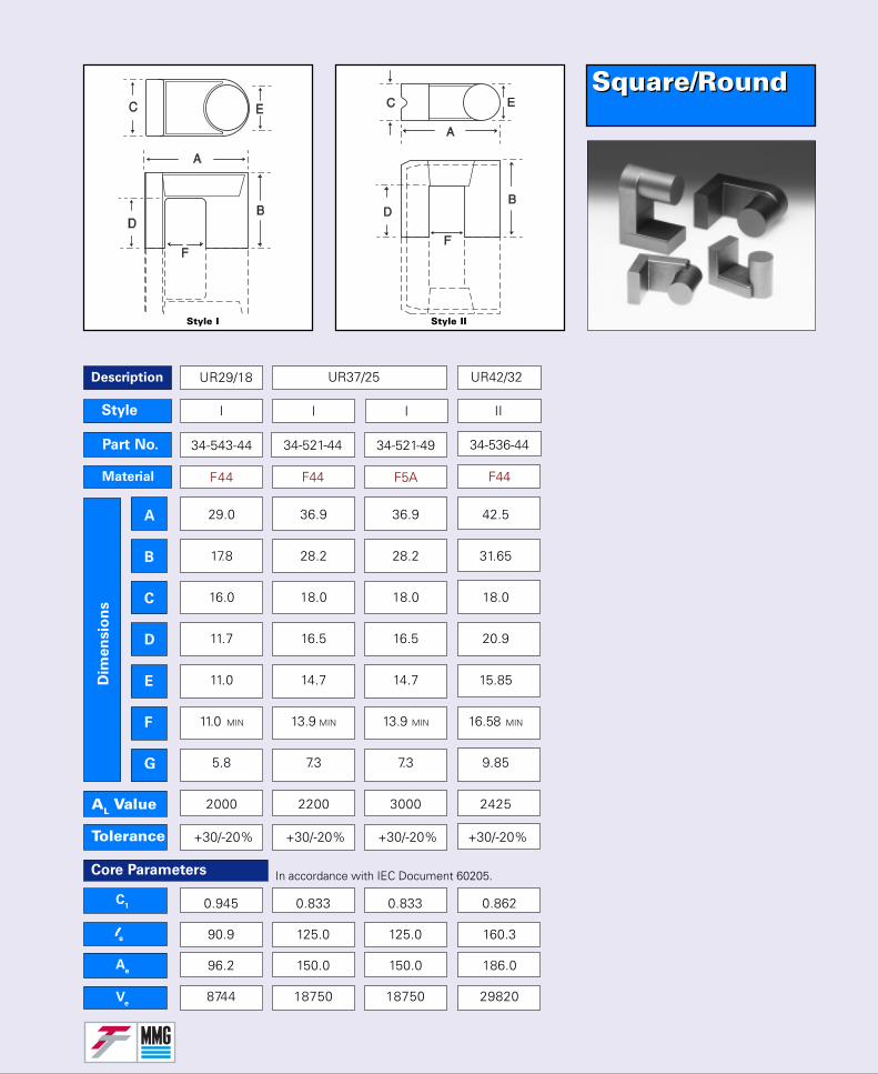
I I II
UR29/18 UR37/25 UR42/32
I
Square/RoundSquare/Round
Part No.
Material
Dim
en
sio
ns
AL Value
Tolerance
C1
llllle
Ae
Ve
A
B
C
D
E
F
G
Core Parameters
Style
34-521-44
F44
34-521-49
F5A
34-536-44
F44
29.0 36.9 36.9 42.5
17.8 28.2 28.2 31.65
16.0 18.0 18.0 18.0
11.7 16.5 16.5 20.9
11.0 14.7 14.7 15.85
11.0 MIN 13.9 MIN 13.9 MIN 16.58 MIN
5.8 7.3 7.3 9.85
2000 2200 3000 2425
+30/-20% +30/-20% +30/-20% +30/-20%
0.945 0.833 0.833 0.862
90.9 125.0 125.0 160.3
96.2 150.0 150.0 186.0
8744 18750 18750 29820
34-543-44
F44
Description
Style I Style II
In accordance with IEC Document 60205.
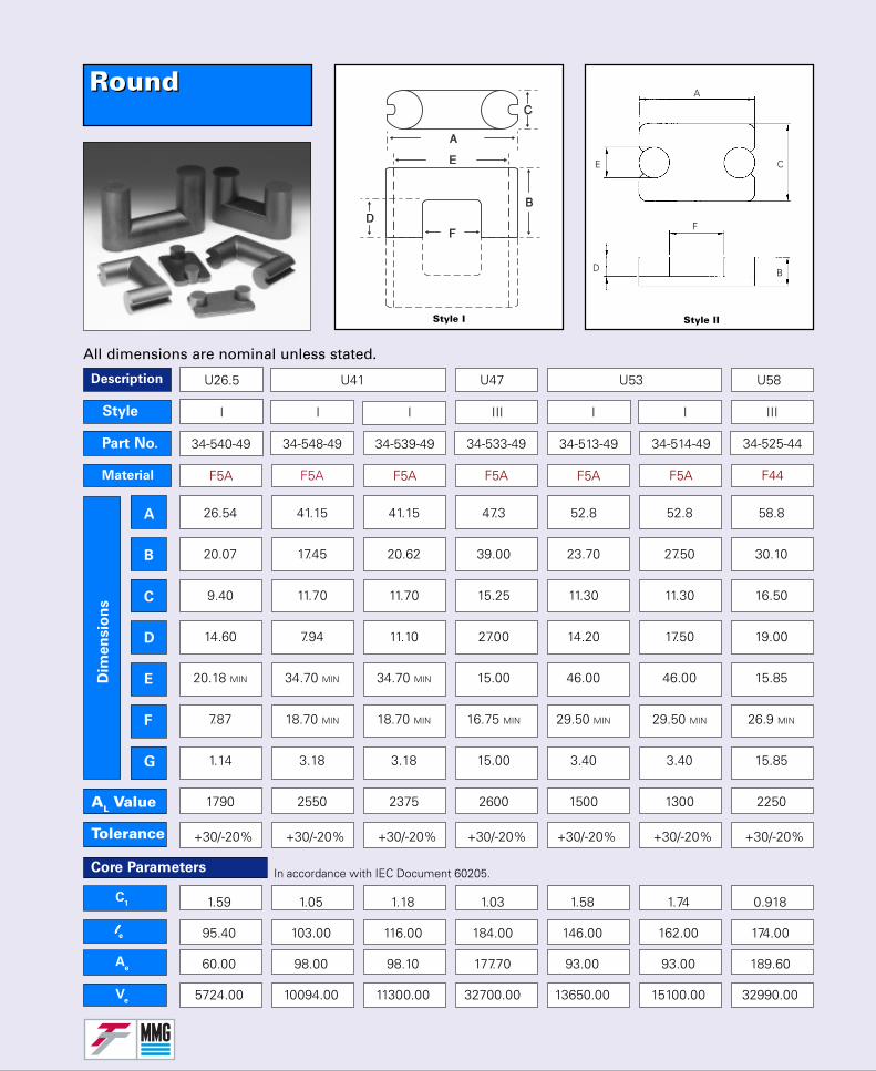
RoundRound
Part No.
Material
Dim
en
sio
ns
AL Value
Tolerance
C1
llllle
Ae
Ve
A
B
C
D
E
F
G
34-540-49
F5A
34-548-49
F5A
34-539-49
F5A
34-533-49
F5A
34-513-49
F5A
34-514-49
F5A
34-525-44
F44
Core Parameters
U26.5 U41 U47 U53 U58
I I I III I I IIIStyle
26.54 41.15 41.15 47.3 52.8 52.8 58.8
20.07 17.45 20.62 39.00 23.70 27.50 30.10
9.40 11.70 11.70 15.25 11.30 11.30 16.50
14.60 7.94 11.10 27.00 14.20 17.50 19.00
20.18 MIN 34.70 MIN 34.70 MIN 15.00 46.00 46.00 15.85
7.87 18.70 MIN 18.70 MIN 16.75 MIN 29.50 MIN 29.50 MIN 26.9 MIN
1.14 3.18 3.18 15.00 3.40 3.40 15.85
1790 2550 2375 2600 1500 1300 2250
+30/-20% +30/-20% +30/-20% +30/-20% +30/-20% +30/-20% +30/-20%
1.59 1.05 1.18 1.03 1.58 1.74 0.918
95.40 103.00 116.00 184.00 146.00 162.00 174.00
60.00 98.00 98.10 177.70 93.00 93.00 189.60
5724.00 10094.00 11300.00 32700.00 13650.00 15100.00 32990.00
All dimensions are nominal unless stated.
Description
A
B
C
D
E
Style I Style II
In accordance with IEC Document 60205.
F
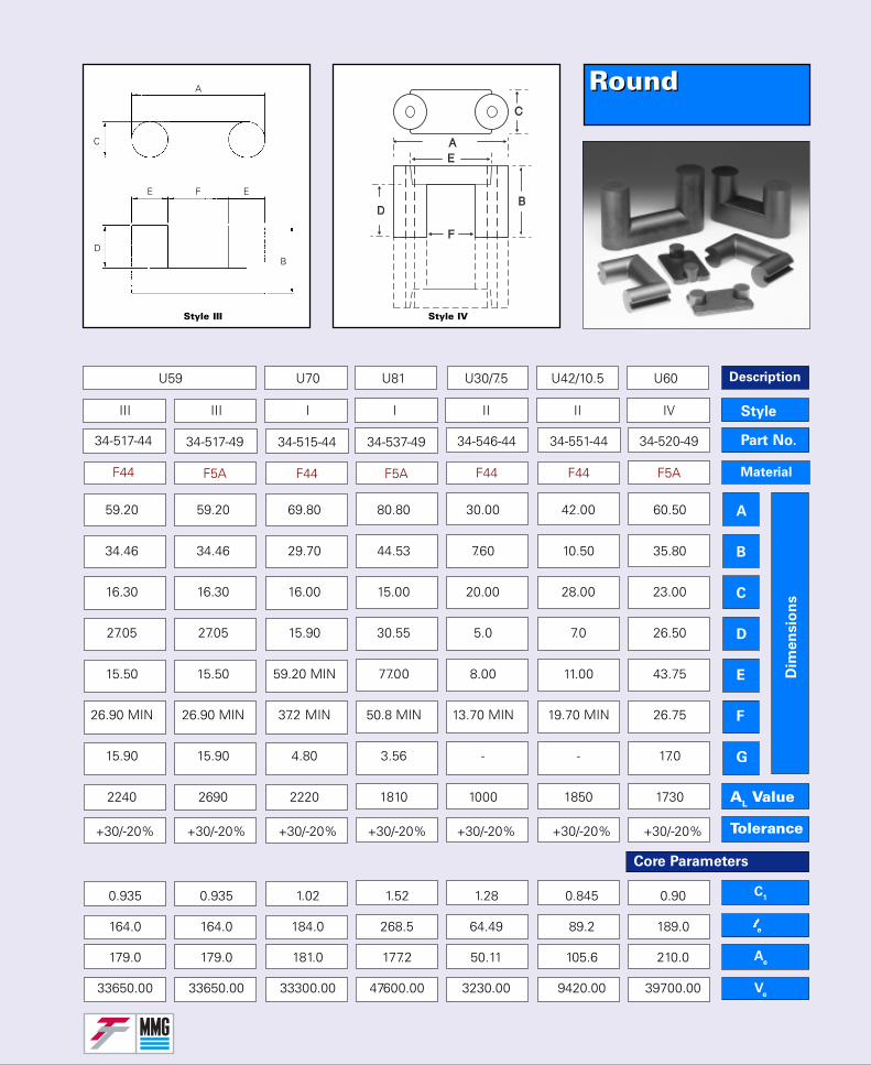
C1
llllle
Ae
Ve
AL Value
Tolerance
Part No.
Material
Dim
en
sio
ns
A
B
C
D
E
F
G
Core Parameters
59.20 59.20 69.80 80.80 30.00 42.00 60.50
34.46 34.46 29.70 44.53 7.60 10.50 35.80
16.30 16.30 16.00 15.00 20.00 28.00 23.00
27.05 27.05 15.90 30.55 5.0 7.0 26.50
15.50 15.50 59.20 MIN 77.00 8.00 11.00 43.75
26.90 MIN 26.90 MIN 37.2 MIN 50.8 MIN 13.70 MIN 19.70 MIN 26.75
15.90 15.90 4.80 3.56 - - 17.0
2240 2690 2220 1810 1000 1850 1730
III III I I II II IV
U59 U70 U81 U30/7.5 U42/10.5 U60
Style
+30/-20% +30/-20% +30/-20% +30/-20% +30/-20% +30/-20% +30/-20%
0.935 0.935 1.02 1.52 1.28 0.845 0.90
164.0 164.0 184.0 268.5 64.49 89.2 189.0
179.0 179.0 181.0 177.2 50.11 105.6 210.0
33650.00 33650.00 33300.00 47600.00 3230.00 9420.00 39700.00
34-546-44
F44
34-515-44
F44
34-517-49
F5A
34-551-44
F44
34-520-49
F5A
34-517-44
F44
34-537-49
F5A
RoundRound
Description
A
B
C
D
E
Style III
F E
Style IV
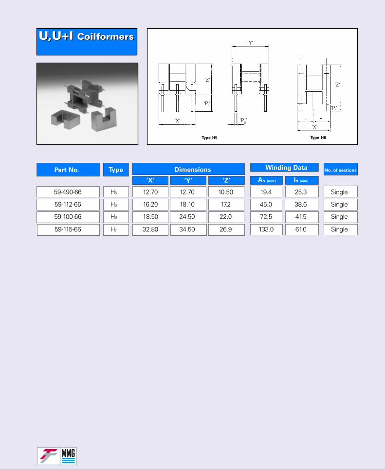
U,U+I CoilformersU,U+I Coilformers
No. of sectionsPart No. Type Dimensions
‘X’ ‘Y’ ‘Z’
Winding Data
AN (mm²) IN (mm)
59-490-66 H5 12.70 12.70 10.50 19.4 25.3 Single
59-112-66 H6 16.20 18.10 17.2 45.0 38.6 Single
59-100-66 H6 18.50 24.50 22.0 72.5 41.5 Single
59-115-66 H7 32.80 34.50 26.9 133.0 61.0 Single
‘Z’
‘X’
‘Y’
‘PL‘
‘P0’
‘Z’
‘X’
‘PL‘
Type H5 Type H6
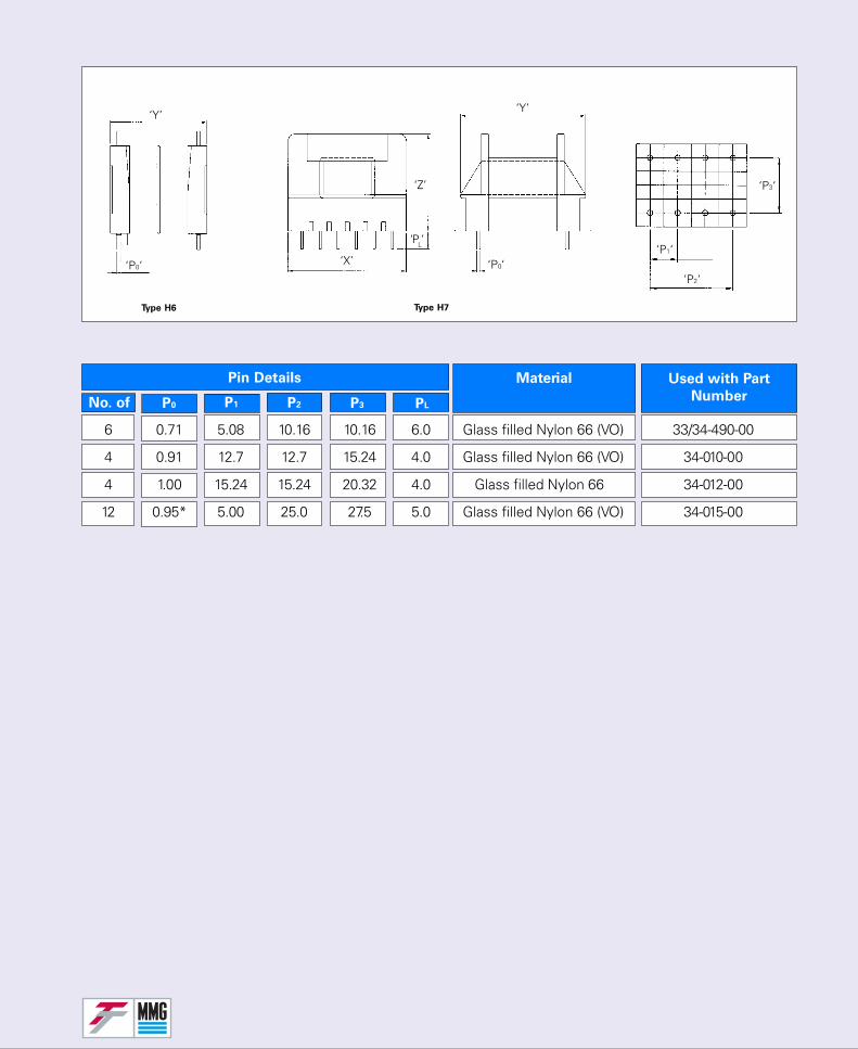
Material
No. of
Used with Part
NumberP1 P2 P3 PL
Pin Details
P0
6 0.71 5.08 10.16 10.16 6.0 Glass filled Nylon 66 (VO) 33/34-490-00
4 0.91 12.7 12.7 15.24 4.0 Glass filled Nylon 66 (VO) 34-010-00
4 1.00 15.24 15.24 20.32 4.0 Glass filled Nylon 66 34-012-00
12 0.95* 5.00 25.0 27.5 5.0 Glass filled Nylon 66 (VO) 34-015-00
‘Z’
‘X’
‘Y’
‘P0‘
‘PL’
‘P0‘‘P1‘
‘P2‘
‘P3‘
Type H6 Type H7
‘Y’
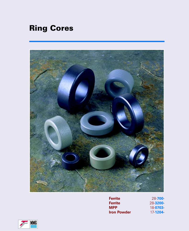
Ring Cores
Ferrite 28-700-Ferrite 28-3200-MPP 18-0703-Iron Powder 17-1204-
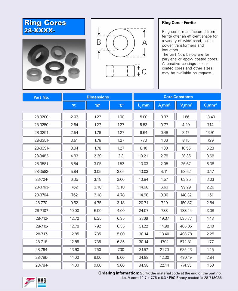
Ring Cores28-XXXX-Ring Cores28-XXXX-
Part No. Dimensions
‘A’ ‘B’ ‘C’
Core Constants
Le mm A
emm2 V
emm3 C
1mm-1
28-3200- 2.03 1.27 1.00 5.00 0.37 1.86 13.40
28-3250- 2.54 1.27 1.27 5.53 0.77 4.29 7.14
28-3251- 2.54 1.78 1.27 6.64 0.48 3.17 13.91
28-3351- 3.51 1.78 1.27 7.70 1.06 8.15 7.29
28-3391- 3.94 1.78 1.27 8.10 1.30 10.55 6.23
28-3482- 4.83 2.29 2.3 10.21 2.78 28.35 3.68
28-3581- 5.84 3.05 1.52 13.03 2.05 26.67 6.38
28-3583- 5.84 3.05 3.05 13.03 4.11 53.52 3.17
28-704- 6.35 3.18 3.00 13.84 4.57 63.25 3.03
28-3763- 7.62 3.18 3.18 14.98 6.63 99.29 2.26
28-3764- 7.62 3.18 4.78 14.98 9.90 148.32 1.51
28-770- 9.52 4.75 3.18 20.71 7.29 150.87 2.84
28-7107- 10.00 6.00 4.00 24.07 7.83 188.44 3.08
28-712- 12.70 6.35 6.35 27.66 19.37 535.77 1.43
28-719- 12.70 7.92 6.35 31.22 14.90 465.05 2.10
28-717- 12.85 7.35 5.00 30.14 13.40 403.78 2.25
28-718- 12.85 7.35 6.35 30.14 17.02 572.81 1.77
28-794- 13.90 7.50 7.00 31.57 21.70 685.23 1.45
28-785- 14.00 9.00 5.00 34.98 12.30 430.19 2.84
28-784- 14.00 9.00 9.00 34.98 22.14 774.35 1.58
Ordering information: Suffix the material code at the end of the part no.i.e. A core 12.7 x 7.75 x 6.3 / F9C Epoxy coated is 28-718C36
Ring Core - Ferrite
Ring cores manufactured fromferrite offer an efficient shape fora variety of wide band, pulse,power transformers andinductors.The part No’s below are forparylene or epoxy coated cores.Alternative coatings or un-coated cores and other sizesmay be available on request.
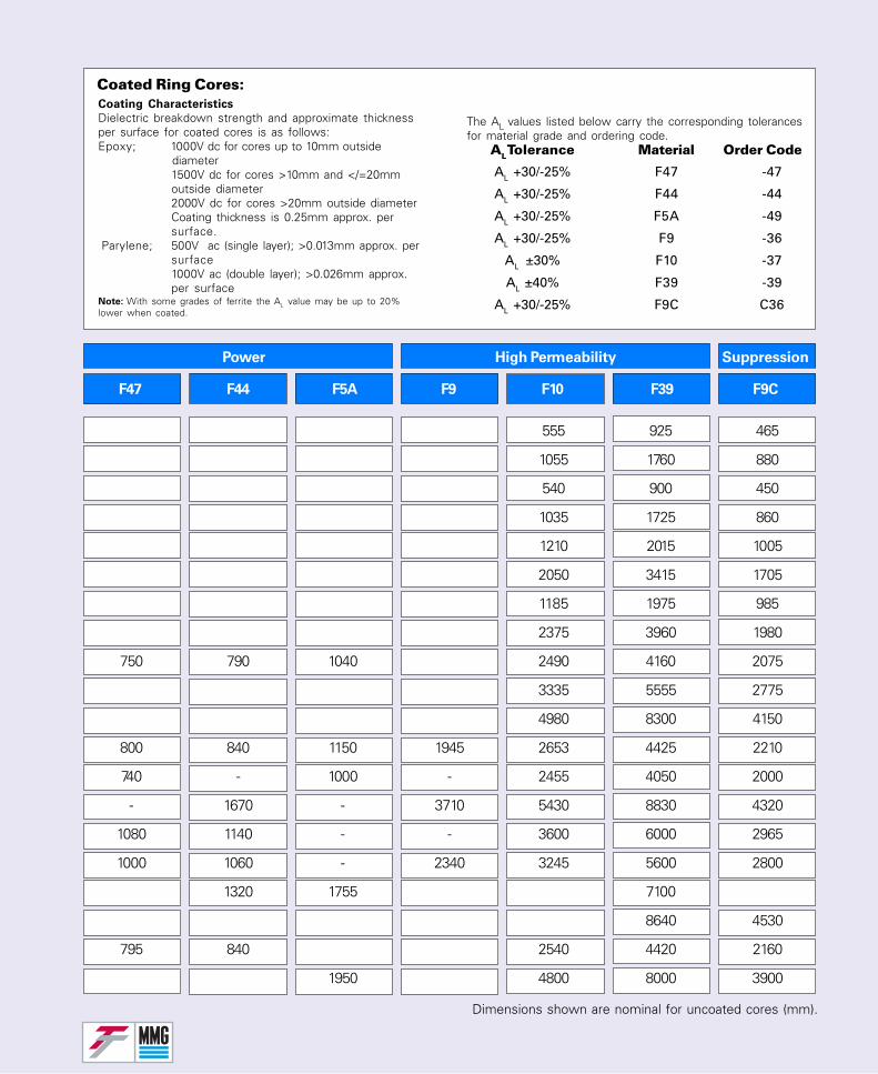
Power High Permeability Suppression
F47 F44 F5A F9 F10 F39 F9C
555 925 465
1055 1760 880
540 900 450
1035 1725 860
1210 2015 1005
2050 3415 1705
1185 1975 985
2375 3960 1980
750 790 1040 2490 4160 2075
3335 5555 2775
4980 8300 4150
800 840 1150 1945 2653 4425 2210
740 - 1000 - 2455 4050 2000
- 1670 - 3710 5430 8830 4320
1080 1140 - - 3600 6000 2965
1000 1060 - 2340 3245 5600 2800
1320 1755 7100
8640 4530
795 840 2540 4420 2160
1950 4800 8000 3900
Coated Ring Cores:
AL Tolerance Material Order Code
AL +30/-25% F47 -47
AL +30/-25% F44 -44
AL +30/-25% F5A -49
AL +30/-25% F9 -36
AL ±30% F10 -37
AL ±40% F39 -39
AL +30/-25% F9C C36
Dimensions shown are nominal for uncoated cores (mm).
Coating Characteristics
Dielectric breakdown strength and approximate thicknessper surface for coated cores is as follows:Epoxy; 1000V dc for cores up to 10mm outside
diameter1500V dc for cores >10mm and </=20mmoutside diameter2000V dc for cores >20mm outside diameterCoating thickness is 0.25mm approx. persurface.
Parylene; 500V ac (single layer); >0.013mm approx. persurface1000V ac (double layer); >0.026mm approx.per surface
Note: With some grades of ferrite the AL value may be up to 20%lower when coated.
The AL values listed below carry the corresponding tolerancesfor material grade and ordering code.

Ring Cores28-XXXX-Ring Cores28-XXXX-
Part No. Dimensions
‘A’ ‘B’ ‘C’
28-759- 16.70 9.60 5.0 39.45 17.33 683 2.28
28-763- 16.70 9.60 6.35 39.45 21.84 861 1.81
28-723- 19.05 12.70 9.52 48.50 29.88 1449 1.62
28-7116- 20.0 10.0 6.80 43.60 33.10 1443 1.32
28-757- 20.0 10.0 10.0 43.60 48.92 2135 0.90
28-782- 22.1 13.7 6.35 54.19 26.10 1414 2.07
28-795- 22.1 13.7 12.7 54.19 51.6 2791 1.05
28-755- 24.0 12.0 12.0 52.0 69.2 3598 0.76
28-780- 25.0 15.0 10.0 60.2 49.0 2950 1.23
28-736- 25.0 15.0 16.0 60.2 78.3 4711 0.77
28-760- 31.5 19.6 7.0 77.3 40.88 3160 1.78
28-756- 31.5 19.6 12.5 77.3 73.0 5645 1.06
28-7140- 36.0 23.0 16.0 89.65 95.89 8596 0.93
28-744- 38.1 25.4 15.90 97.10 99.4 9650 0.97
28-743- 38.1 25.4 19.05 97.10 119.4 11580 0.81
28-796- 38.1 19.6 12.70 84.21 113.24 9545 0.74
28-797- 38.1 19.6 25.40 84.29 226.49 19090 0.37
28-7132- 49.0 31.8 19.0 123.05 160.88 19796 0.76
28-761- 63.0 38.0 25.0 152.0 305.0 46530 0.50
28-7797- 78.0 45.0 14.0 183.8 225.26 41403 0.82
Core Constants
Le mm A
emm2 V
emm3 C
1mm-1
Ordering information: Suffix the material code at the end of the part no.i.e. A core 12.7 x 7.75 x 6.3 / F9C Epoxy coated is 28-718C36
Ring Core - Ferrite
Ring cores manufactured fromferrite offer an efficient shape fora variety of wide band, pulse,power transformers andinductors.The part No’s below are forparylene or epoxy coated cores.Alternative coatings or un-coated cores and other sizesmay be available on request.
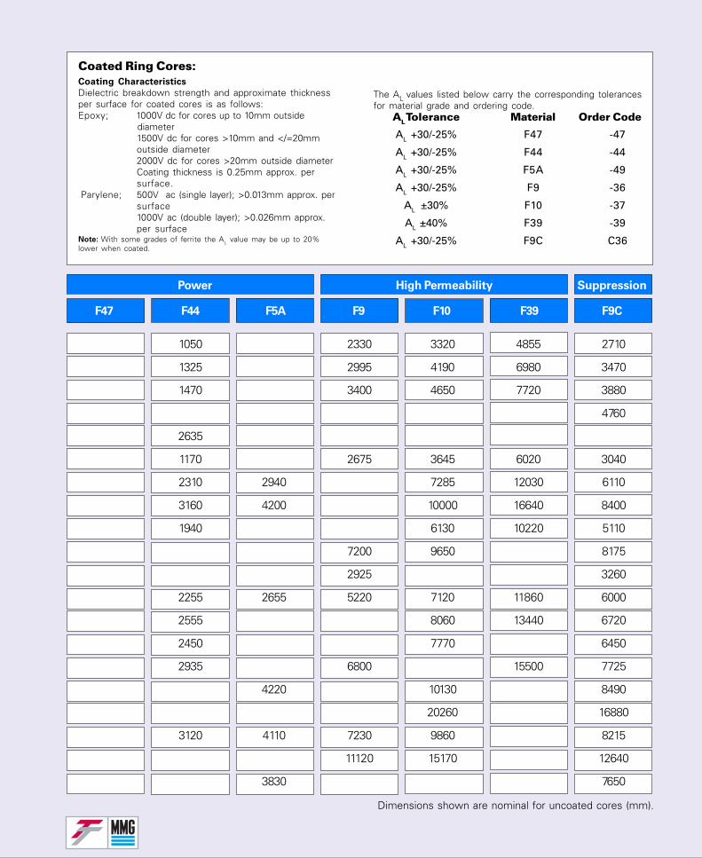
Power High Permeability Suppression
F47 F44 F5A F9 F10 F39 F9C
1050 2330 3320 4855 2710
1325 2995 4190 6980 3470
1470 3400 4650 7720 3880
4760
2635
1170 2675 3645 6020 3040
2310 2940 7285 12030 6110
3160 4200 10000 16640 8400
1940 6130 10220 5110
7200 9650 8175
2925 3260
2255 2655 5220 7120 11860 6000
2555 8060 13440 6720
2450 7770 6450
2935 6800 15500 7725
4220 10130 8490
20260 16880
3120 4110 7230 9860 8215
11120 15170 12640
3830 7650
Dimensions shown are nominal for uncoated cores (mm).
Coated Ring Cores:
AL Tolerance Material Order Code
AL +30/-25% F47 -47
AL +30/-25% F44 -44
AL +30/-25% F5A -49
AL +30/-25% F9 -36
AL ±30% F10 -37
AL ±40% F39 -39
AL +30/-25% F9C C36
Coating Characteristics
Dielectric breakdown strength and approximate thicknessper surface for coated cores is as follows:Epoxy; 1000V dc for cores up to 10mm outside
diameter1500V dc for cores >10mm and </=20mmoutside diameter2000V dc for cores >20mm outside diameterCoating thickness is 0.25mm approx. persurface.
Parylene; 500V ac (single layer); >0.013mm approx. persurface1000V ac (double layer); >0.026mm approx.per surface
Note: With some grades of ferrite the AL value may be up to 20%lower when coated.
The AL values listed below carry the corresponding tolerancesfor material grade and ordering code.
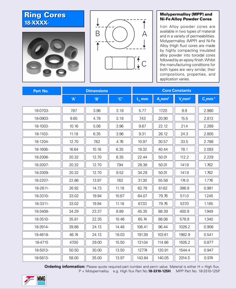
Ring Cores18-XXXX-Ring Cores18-XXXX-
Part No. Dimensions
‘A’ ‘B’ ‘C’
Core Constants
Le mm A
emm2 V
emm3 C
1mm-1
18-0703- 7.87 3.96 3.18 5.77 17.20 9.9 2.980
18-0903- 9.65 4.78 3.18 7.43 20.90 15.5 2.813
18-1003- 10.16 5.08 3.96 9.67 22.12 21.4 2.289
18-1103- 11.18 6.35 3.96 9.31 26.12 24.3 2.805
18-1204- 12.70 7.62 4.76 10.97 30.57 33.5 2.788
18-1606- 16.64 10.16 6.35 19.32 40.44 78.1 2.093
18-2006- 20.32 12.70 6.35 22.44 50.01 112.2 2.229
18-2007- 20.32 12.70 7.94 28.38 50.01 141.9 1.762
18-2009- 20.32 12.70 9.52 34.29 50.01 141.9 1.762
18-2207- 22.86 13.97 7.62 31.30 55.58 174.0 1.776
18-2611- 26.92 14.73 11.18 62.78 61.62 386.9 0.981
18-3310- 33.02 19.94 10.67 64.07 79.76 511.0 1.245
18-3311- 33.02 19.94 11.18 67.33 79.76 537.0 1.185
18-3408- 34.29 23.37 8.89 45.35 88.39 400.9 1.949
18-3510- 35.81 22.35 10.46 65.74 88.06 578.9 1.340
18-3914- 39.88 24.13 14.48 106.41 96.44 1026.2 0.906
18-4618- 46.74 24.13 18.03 191.39 103.61 1982.9 0.541
18-4715 47.00 29.00 15.50 131.04 114.86 1505.2 0.877
18-5013- 50.50 30.00 13.50 127.74 120.91 1544.4 0.947
18-5813- 58.00 35.00 13.97 143.84 140.05 2014.5 0.974
Molypermalloy (MPP) andNi-Fe Alloy Powder Cores
Iron Alloy powder cores areavailable in two types of materialand in a variety of permeabilities.Molypermalloy (MPP) and Ni-FeAlloy (High flux) cores are madeby highly compacting insulatedalloy powder into toroidal coresfollowed by an epoxy finish. Whilstthe manufacturing conditions forboth types are very similar, theircompositions, properties, andapplication varies.
Ordering information: Please quote required part number and perm value. Material is either H = High flux.P = Molypermalloy e.g. High flux Part No.18-3310-125H. MPP Part No. 18-3310-125P.
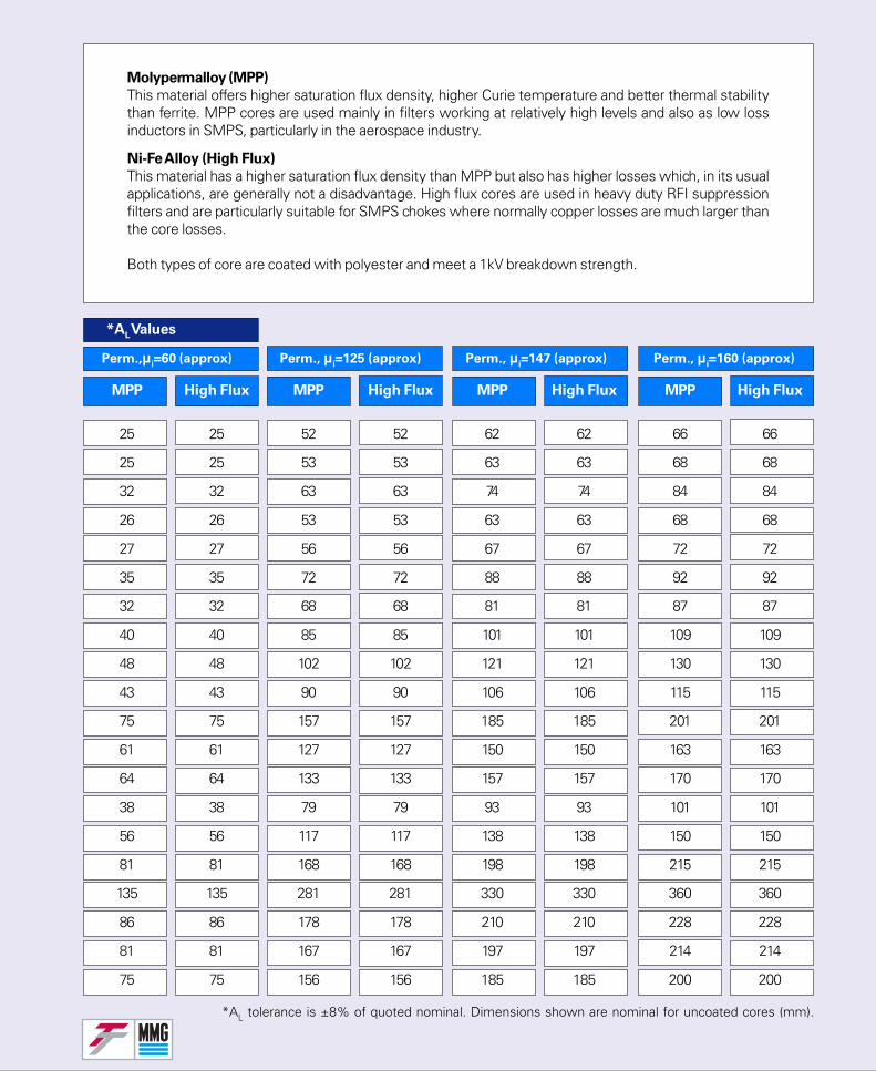
MPP High Flux MPP High Flux MPP High Flux MPP High Flux
Perm.,µi=60 (approx) Perm., µ
i=125 (approx) Perm., µ
i=147 (approx) Perm., µ
i=160 (approx)
Molypermalloy (MPP)
This material offers higher saturation flux density, higher Curie temperature and better thermal stabilitythan ferrite. MPP cores are used mainly in filters working at relatively high levels and also as low lossinductors in SMPS, particularly in the aerospace industry.
Ni-Fe Alloy (High Flux)
This material has a higher saturation flux density than MPP but also has higher losses which, in its usualapplications, are generally not a disadvantage. High flux cores are used in heavy duty RFI suppressionfilters and are particularly suitable for SMPS chokes where normally copper losses are much larger thanthe core losses.
Both types of core are coated with polyester and meet a 1kV breakdown strength.
25 25 52 52 62 62 66 66
25 25 53 53 63 63 68 68
32 32 63 63 74 74 84 84
26 26 53 53 63 63 68 68
27 27 56 56 67 67 72 72
35 35 72 72 88 88 92 92
32 32 68 68 81 81 87 87
40 40 85 85 101 101 109 109
48 48 102 102 121 121 130 130
43 43 90 90 106 106 115 115
75 75 157 157 185 185 201 201
61 61 127 127 150 150 163 163
64 64 133 133 157 157 170 170
38 38 79 79 93 93 101 101
56 56 117 117 138 138 150 150
81 81 168 168 198 198 215 215
135 135 281 281 330 330 360 360
86 86 178 178 210 210 228 228
81 81 167 167 197 197 214 214
75 75 156 156 185 185 200 200
*AL tolerance is ±8% of quoted nominal. Dimensions shown are nominal for uncoated cores (mm).
*AL Values
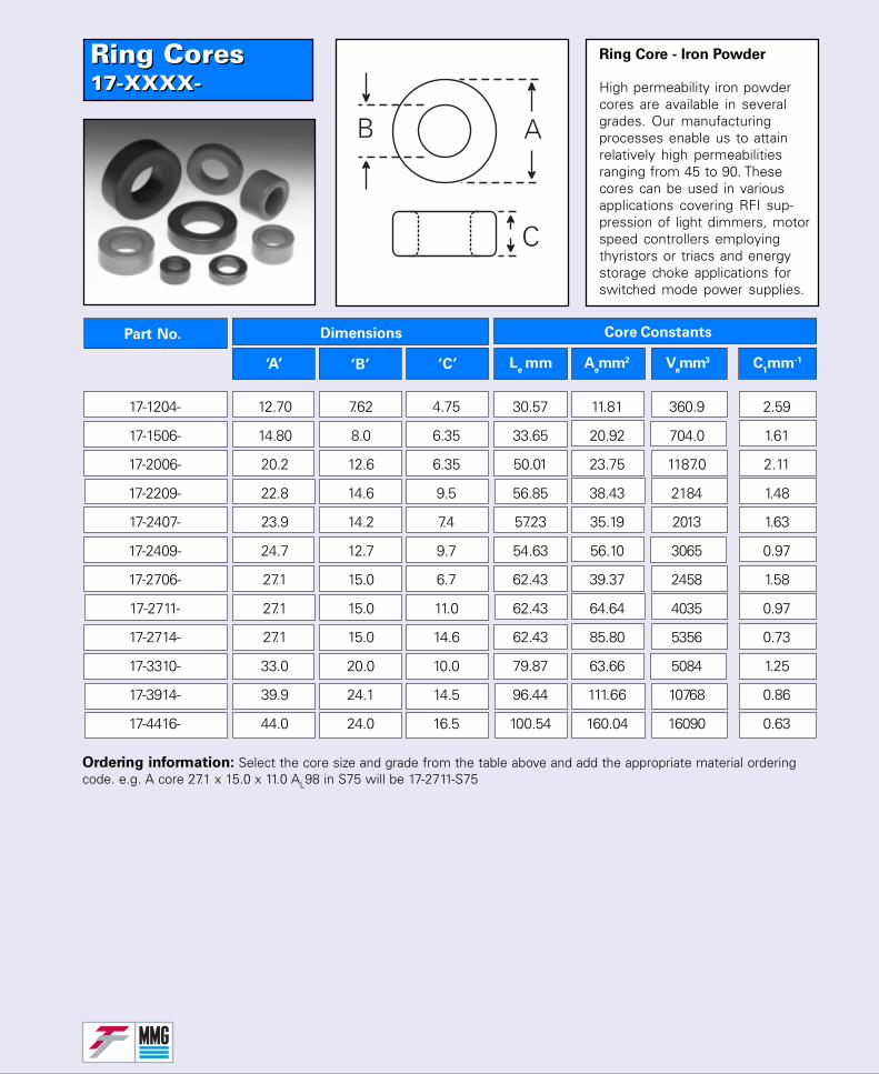
Ring Cores17-XXXX-Ring Cores17-XXXX-
Part No. Dimensions
‘A’ ‘B’ ‘C’
Core Constants
Le mm A
emm2 V
emm3 C
1mm-1
17-1204- 12.70 7.62 4.75 30.57 11.81 360.9 2.59
17-1506- 14.80 8.0 6.35 33.65 20.92 704.0 1.61
17-2006- 20.2 12.6 6.35 50.01 23.75 1187.0 2.11
17-2209- 22.8 14.6 9.5 56.85 38.43 2184 1.48
17-2407- 23.9 14.2 7.4 57.23 35.19 2013 1.63
17-2409- 24.7 12.7 9.7 54.63 56.10 3065 0.97
17-2706- 27.1 15.0 6.7 62.43 39.37 2458 1.58
17-2711- 27.1 15.0 11.0 62.43 64.64 4035 0.97
17-2714- 27.1 15.0 14.6 62.43 85.80 5356 0.73
17-3310- 33.0 20.0 10.0 79.87 63.66 5084 1.25
17-3914- 39.9 24.1 14.5 96.44 111.66 10768 0.86
17-4416- 44.0 24.0 16.5 100.54 160.04 16090 0.63
Ordering information: Select the core size and grade from the table above and add the appropriate material orderingcode. e.g. A core 27.1 x 15.0 x 11.0 AL98 in S75 will be 17-2711-S75
Ring Core - Iron Powder
High permeability iron powdercores are available in severalgrades. Our manufacturingprocesses enable us to attainrelatively high permeabilitiesranging from 45 to 90. Thesecores can be used in variousapplications covering RFI sup-pression of light dimmers, motorspeed controllers employingthyristors or triacs and energystorage choke applications forswitched mode power supplies.
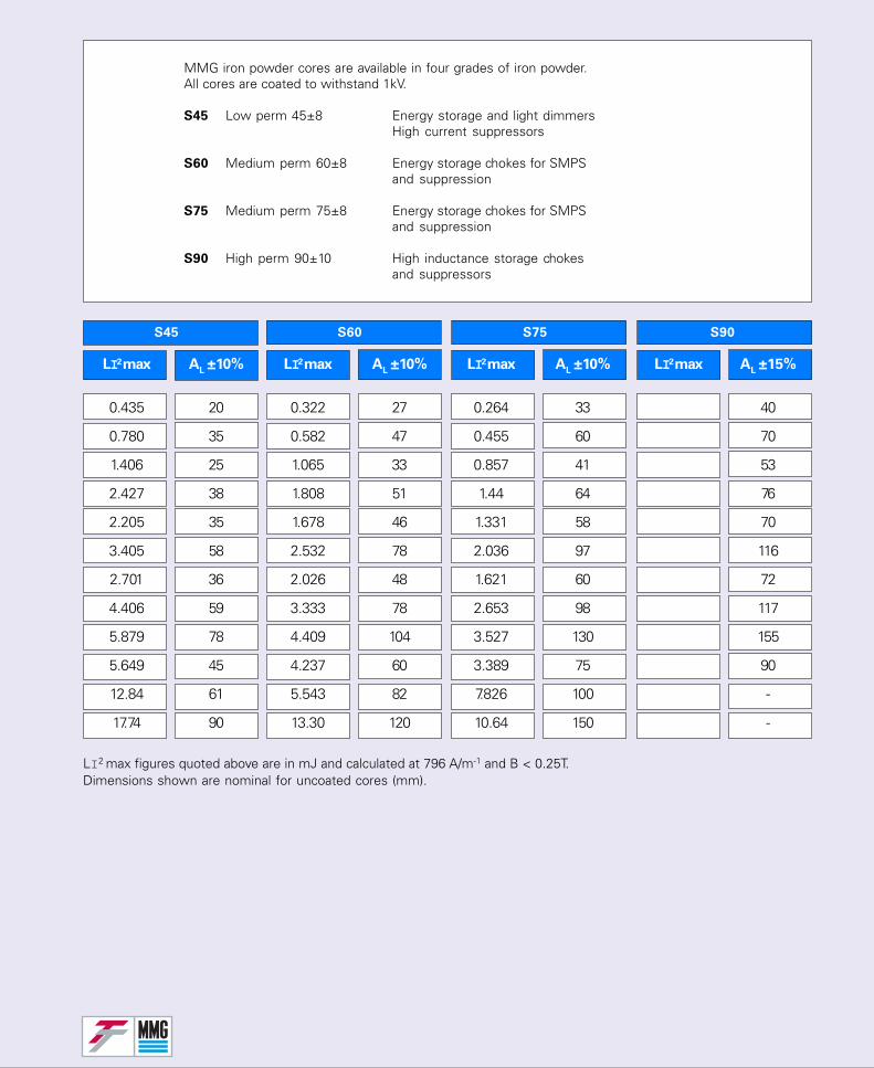
LI2 max AL ±10% LI2 max A
L ±10% LI2 max A
L ±10% LI2 max A
L ±15%
S45 S60 S75 S90
LI2 max figures quoted above are in mJ and calculated at 796 A/m-1 and B < 0.25T.Dimensions shown are nominal for uncoated cores (mm).
MMG iron powder cores are available in four grades of iron powder.All cores are coated to withstand 1kV.
S45 Low perm 45±8 Energy storage and light dimmersHigh current suppressors
S60 Medium perm 60±8 Energy storage chokes for SMPSand suppression
S75 Medium perm 75±8 Energy storage chokes for SMPSand suppression
S90 High perm 90±10 High inductance storage chokesand suppressors
0.435 20 0.322 27 0.264 33 40
0.780 35 0.582 47 0.455 60 70
1.406 25 1.065 33 0.857 41 53
2.427 38 1.808 51 1.44 64 76
2.205 35 1.678 46 1.331 58 70
3.405 58 2.532 78 2.036 97 116
2.701 36 2.026 48 1.621 60 72
4.406 59 3.333 78 2.653 98 117
5.879 78 4.409 104 3.527 130 155
5.649 45 4.237 60 3.389 75 90
12.84 61 5.543 82 7.826 100 -
17.74 90 13.30 120 10.64 150 -
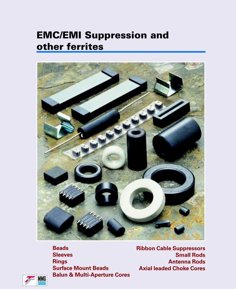
EMC/EMI Suppression andother ferrites
Beads
Sleeves
Rings
Surface Mount Beads
Balun & Multi-Aperture Cores
Ribbon Cable Suppressors
Small Rods
Antenna Rods
Axial leaded Choke Cores
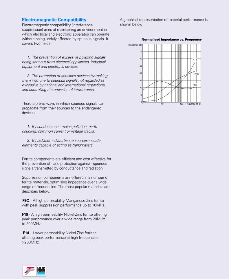
Electromagnetic CompatibilityElectromagnetic compatibility (interferencesuppression) aims at maintaining an environment inwhich electrical and electronic apparatus can operatewithout being unduly affected by spurious signals. Itcovers two fields:
1. The prevention of excessive polluting signalsbeing sent out from electrical appliances, industrialequipment and electronic devices.
2. The protection of sensitive devices by makingthem immune to spurious signals not regarded asexcessive by national and international regulations,and controlling the emission of interference.
There are two ways in which spurious signals canpropagate from their sources to the endangereddevices:
1. By conductance - mains pollution, earthcoupling, common current or voltage tracks.
2. By radiation - disturbance sources includeelements capable of acting as transmitters.
Ferrite components are efficient and cost effective forthe prevention of - and protection against - spurioussignals transmitted by conductance and radiation.
Suppression components are offered in a number offerrite materials, optimising impedance over a widerange of frequencies. The most popular materials aredescribed below.
F9C - A high permeability Manganese-Zinc ferritewith peak suppression performance up to 10MHz.
F19 - A high permeability Nickel-Zinc ferrite offeringpeak performance over a wide range from 20MHzto 200MHz.
F14 - Lower permeability Nickel-Zinc ferritesoffering peak performance at high frequencies>200MHz.
Normalised Impedance vs. Frequency
A graphical representation of material performance isshown below.
F
Flat Ribbon Cable SuppressorsA simple method of suppression of RFI in ribboncables is offered by MMG - Flat ribbon cablesuppressors in F19 material.These components are available in two types: thesolid single piece version through which the cable isthreaded, and the split version which may beconveniently fitted to existing equipment assembliesusing clips.
Beads and tubesCylindrical beads are among the simplestcomponents for suppression use and are threadedover conductors, as the impedance is, in general,directly proportional to the length of the bead. Itshould be noted that at frequencies above eachmaterial’s optimum range, it is advisable to use anumber of shorter beads in preference to a singlelong bead.
Two terminal (leaded) chokesIn their simplest form, chokes are ferrite rods with asingle winding, preferably close to the rod becausedistant turns hardly couple to the rod and contributevery little to the inductance of a choke. Such chokesmay be used as LC filter components or inserted inthe lines to and from devices producing(asymmetrical) interference. At low frequencies, thereactance is low and does not affect the flow ofdesired currents, but at higher frequencies thereactance is high enough to attenuate theinterference, generating in or endangering theprotected device.Ferrite ring, pot, RM and other closed cores canprovide much higher inductance values required forsuppression at lower frequencies, but they are moreprone to saturation when high operational currentshave to be handled. In some conditions, iron powdertoroids, having much higher saturation inductionthan any other ferrite grade, may be useful.
Toroidal coresToroidal cores are widely used as designed filtersand chokes in electronic circuits, for example, Mainsfilters, common and differential mode chokes. Theyhave the advantage of being large enough to allowfor multiple turns of wire.
Surface mount beadsThe MMG surface mount bead inductors in grade F19give excellent suppression of RFI in the range 10-300MHz. Two sizes are available and are suppliedon reels for automatic insertion.
Multi-Aperture coresMulti-Aperture cores are designed as suppressioncomponents which are compact in size and providehigh resistive impedence over a wide frequencyband. These cores avoid the self resonance effectsexperienced with single aperture cores wound withmultiple turns.
Transformer (Balun) coresOriginally designed for balun transformers, matchingbalanced to unbalanced circuits in the televisionfrequency spectrum, these cores can also be usedfor wideband and pulse transformers and interfer-ence suppression.
Surface mount four-way beadA multi-hole bead for printed circuit boards offersexcellent attenuation at frequencies from 25-100MHz. Good isolation between each single turnwinding means the bead can be used on up to fourlines simultaneously or with two, three or four turnson a single line.
Rods and SlabsSmall rods are generally used to increase theinductance of a coil. The magnetic current is consid-ered to be very open and therefore the mechanicaldimensions of the rod or slab have more influenceon the inductance than the ferrite material’s perme-ability.With the magnetic circuit being open, rods can beused at higher current levels than other ferritecomponents and some typical applications are in-line chokes, ignition coils, loud speaker crossovers.The high surface resistivity of Ni-Zn material lendsitself to being directly wound.Long rods can be used for receiving antenna andMMG recommend:-F6 LW up to 500kHzF14 MW/SW up to 2MHzF16 MW/SW up to 10MHz.Fluted rods in F6 are designed to stop dimensionalresonance at the lower kHz frequency range.
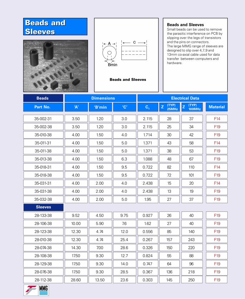
Beads andSleevesBeads andSleeves
Part No.
Dimensions
‘A’ ‘B’min ‘C’
Beads Electrical Data
35-002-31 3.50 1.20 3.0 2.115 28 37 F14
35-002-38 3.50 1.20 3.0 2.115 25 34 F19
35-010-38 4.00 1.50 4.0 1.714 30 42 F19
35-011-31 4.00 1.50 5.0 1.371 43 58 F14
35-011-38 4.00 1.50 5.0 1.371 38 53 F19
35-013-38 4.00 1.50 6.3 1.088 48 67 F19
35-018-31 4.00 1.50 9.5 0.722 82 110 F14
35-018-38 4.00 1.50 9.5 0.722 72 101 F19
35-031-31 4.00 2.00 4.0 2.438 15 20 F14
35-031-38 4.00 2.00 4.0 2.438 13 19 F19
35-032-38 4.00 2.00 5.0 1.95 27 37 F19
28-133-38 9.52 4.50 9.75 0.927 26 40 F19
28-106-38 10.00 5.90 7.6 1.62 27 40 F19
28-123-38 12.30 4.74 12.0 0.556 85 140 F19
28-010-38 12.30 4.74 25.4 0.267 157 243 F19
28-074-38 14.30 7.00 28.6 0.326 150 220 F19
28-108-38 17.50 9.30 12.7 0.824 55 88 F19
28-129-38 17.50 9.30 14.0 0.747 64 96 F19
28-076-38 17.50 9.30 28.5 0.367 136 218 F19
28-112-38 28.60 13.50 23.6 0.303 145 250 F19
C1
Z(TYP)
25MHzZ
(TYP)
100MHzMaterial
Beads and Sleeves
Beads and SleevesSmall beads can be used to removethe parasitic interference on PCB byslipping over the legs of transistorsand the pins on connectors.The large MMG range of sleeves aredesigned to slip over 4,7,9 and13mm co-axial cable used for datatransfer between computers andhardware.
Sleeves
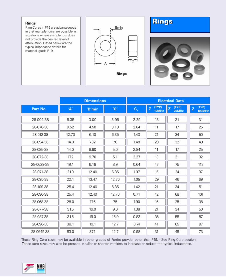
RingsRings
Rings
Part No.
Dimensions
‘A’ ‘B’min ‘C’
Electrical Data
C1
Z(TYP)
10MHzZ
(TYP)
25MHzZ
(TYP)
100MHz
28-002-38 6.35 3.00 3.96 2.29 13 21 31
28-070-38 9.52 4.50 3.18 2.84 11 17 25
28-012-38 12.70 6.10 6.35 1.43 21 34 50
28-094-38 14.0 7.32 7.0 1.48 20 32 49
28-085-38 14.0 8.60 5.0 2.84 11 17 25
28-072-38 17.2 9.70 5.1 2.27 13 21 32
28-0629-38 19.1 6.18 8.9 0.64 47 75 113
28-071-38 21.0 12.40 6.35 1.97 15 24 37
28-095-38 22.1 13.47 12.70 1.05 29 46 69
28-109-38 25.4 12.40 6.35 1.42 21 34 51
28-090-38 25.4 12.40 12.70 0.71 42 68 101
28-068-38 28.0 17.6 7.5 1.90 16 25 38
28-077-38 31.5 19.0 9.0 1.38 21 34 50
28-087-38 31.5 19.0 15.9 0.83 36 58 87
28-096-38 38.1 19.1 12.7 0.74 41 65 97
28-0645-38 63.0 37.1 12.7 0.98 31 49 73
RingsRing Cores in F19 are advantageousin that multiple turns are possible insituations where a single turn doesnot provide the desired level ofattenuation. Listed below are thetypical impedance details formaterial grade F19.
These Ring Core sizes may be available in other grades of Ferrite powder other than F19. - See Ring Core section. These core sizes may also be pressed in taller or shorter versions to increase or reduce the typical inductance.
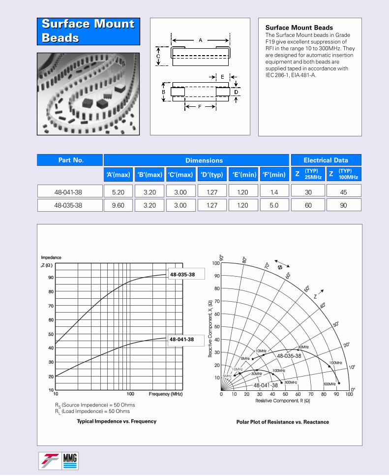
Surface MountBeadsSurface MountBeads
Dimensions
Surface Mount BeadsThe Surface Mount beads in GradeF19 give excellent suppression ofRFI in the range 10 to 300MHz. Theyare designed for automatic insertionequipment and both beads aresupplied taped in accordance withIEC 286-1, EIA 481-A.
48-041-38 5.20 3.20 3.00 1.27 1.20 1.4 30 45
48-035-38 9.60 3.20 3.00 1.27 1.20 5.0 60 90
Typical Impedence vs. Frequency Polar Plot of Resistance vs. Reactance
‘A’(max) ‘B’(max) ‘C’(max) ‘D’(typ) ‘E’(min) ‘F’(min)
Electrical DataPart No.
Z(TYP)
25MHzZ
(TYP)
100MHz
RS (Source Impedence) = 50 OhmsRL (Load Impedence) = 50 Ohms
48-035-38
48-041-38
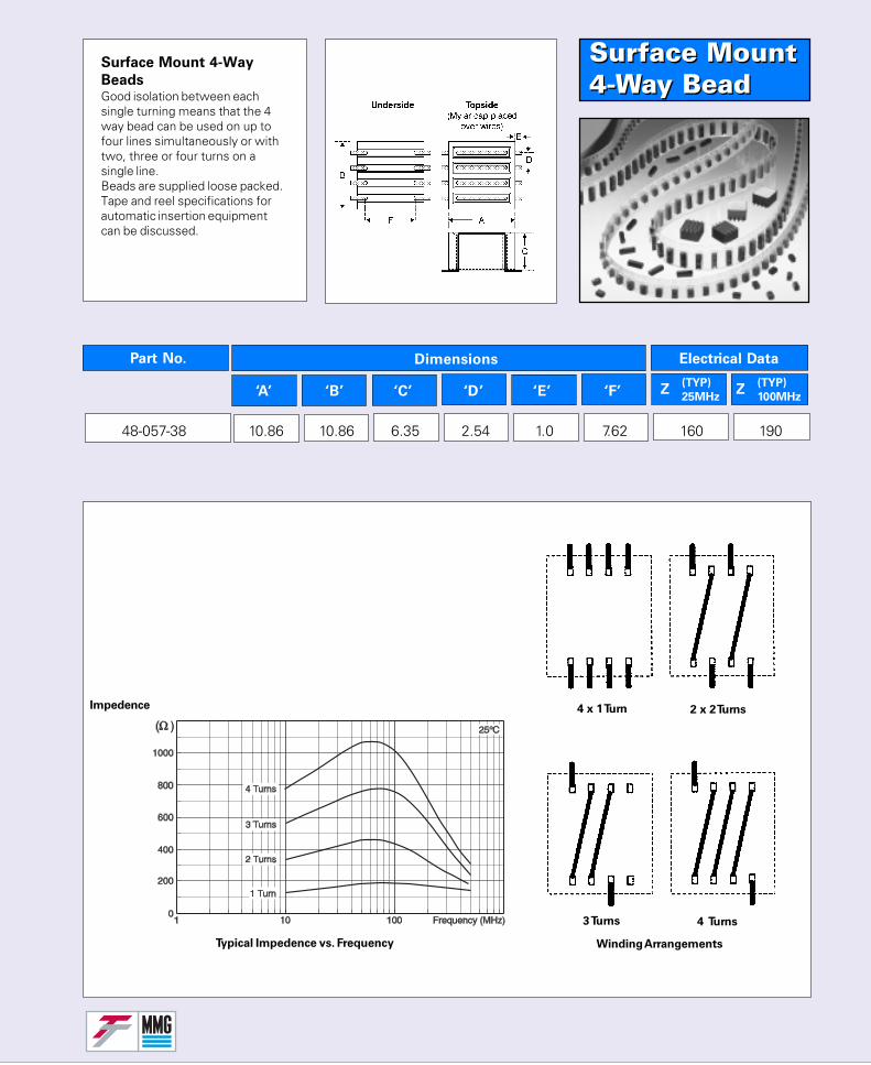
Surface Mount4-Way BeadSurface Mount4-Way Bead
48-057-38 10.86 10.86 6.35 2.54 1.0 7.62 160 190
Surface Mount 4-Way
BeadsGood isolation between eachsingle turning means that the 4way bead can be used on up tofour lines simultaneously or withtwo, three or four turns on asingle line.Beads are supplied loose packed.Tape and reel specifications forautomatic insertion equipmentcan be discussed.
Impedence
Typical Impedence vs. Frequency
4 x 1 Turn 2 x 2 Turns
4 Turns3 Turns
Winding Arrangements
Dimensions
‘A’ ‘B’ ‘C’ ‘D’ ‘E’ ‘F’
Electrical DataPart No.
Z(TYP)
25MHzZ
(TYP)
100MHz
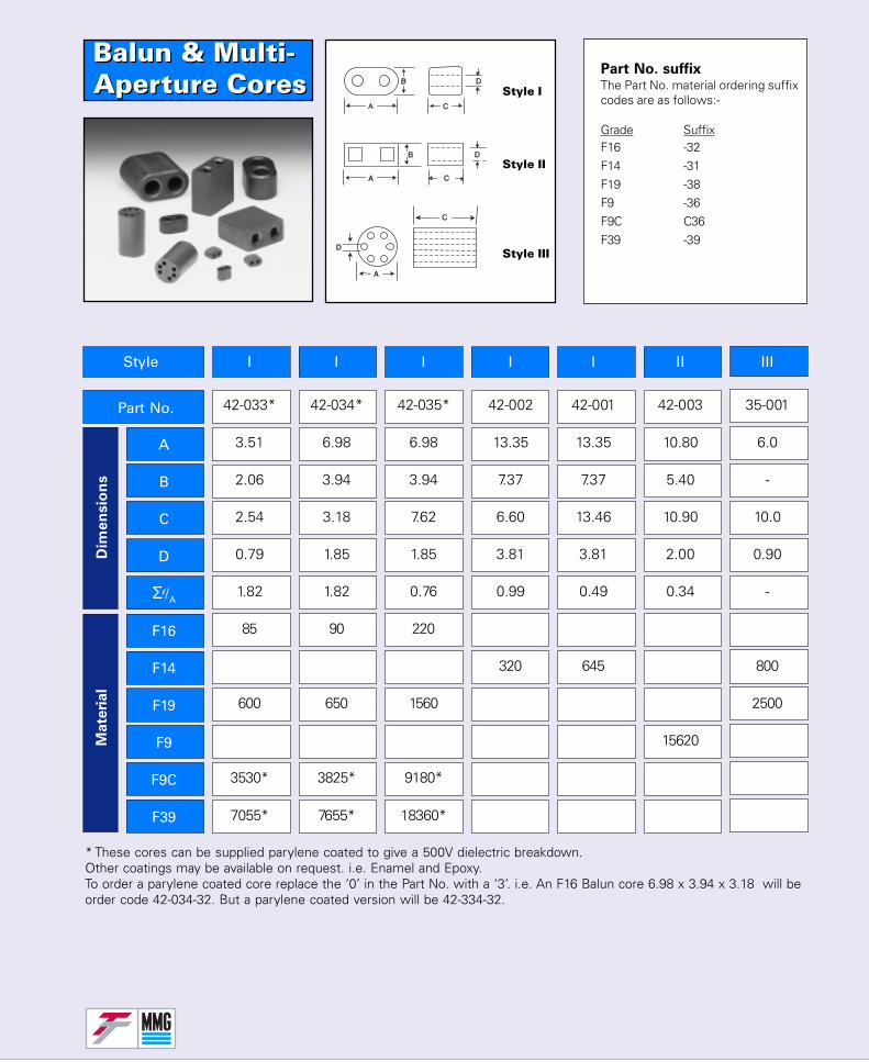
Balun & Multi-Aperture CoresBalun & Multi-Aperture Cores
Ma
teri
al
Dim
en
sio
ns
Style
Part No. 42-033* 42-034* 42-035* 42-002 42-001 42-003 35-001
3.51 6.98 6.98 13.35 13.35 10.80 6.0
2.06 3.94 3.94 7.37 7.37 5.40 -
2.54 3.18 7.62 6.60 13.46 10.90 10.0
0.79 1.85 1.85 3.81 3.81 2.00 0.90
1.82 1.82 0.76 0.99 0.49 0.34 -
85 90 220
320 645 800
600 650 1560 2500
15620
3530* 3825* 9180*
7055* 7655* 18360*
A
B
C
D
Σl/A
F16
F14
F19
F9
F9C
F39
I I I I I II III
Style I
Style III
Style II
* These cores can be supplied parylene coated to give a 500V dielectric breakdown.Other coatings may be available on request. i.e. Enamel and Epoxy.To order a parylene coated core replace the ‘0’ in the Part No. with a ‘3’. i.e. An F16 Balun core 6.98 x 3.94 x 3.18 will beorder code 42-034-32. But a parylene coated version will be 42-334-32.
Part No. suffixThe Part No. material ordering suffixcodes are as follows:-
Grade SuffixF16 -32F14 -31F19 -38F9 -36F9C C36F39 -39
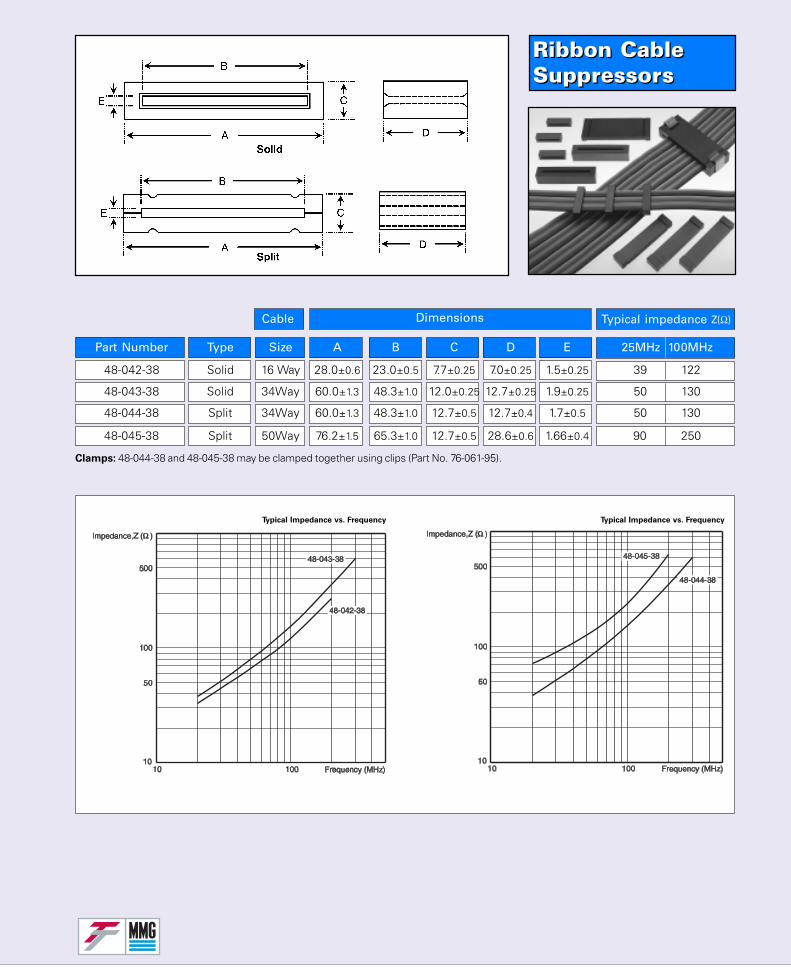
Ribbon CableSuppressorsRibbon CableSuppressors
Part Number Type Size A B C D E 25MHz 100MHz
48-042-38 Solid 16 Way 28.0±0.6 23.0±0.5 7.7±0.25 7.0±0.25 1.5±0.25 39 122
48-043-38 Solid 34Way 60.0±1.3 48.3±1.0 12.0±0.25 12.7±0.25 1.9±0.25 50 130
48-044-38 Split 34Way 60.0±1.3 48.3±1.0 12.7±0.5 12.7±0.4 1.7±0.5 50 130
48-045-38 Split 50Way 76.2±1.5 65.3±1.0 12.7±0.5 28.6±0.6 1.66±0.4 90 250
Typical impedance Z(Ω)Cable Dimensions
Clamps: 48-044-38 and 48-045-38 may be clamped together using clips (Part No. 76-061-95).
Typical Impedance vs. Frequency Typical Impedance vs. Frequency
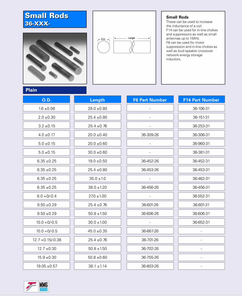
Small Rods36-XXX-Small Rods36-XXX-
Plain
O.D. Length F6 Part Number F14 Part Number
1.6 ±0.08 28.0 ±0.80 - 36-106-31
2.0 ±0.30 25.4 ±0.80 - 36-151-31
3.2 ±0.15 25.4 ±0.76 - 36-253-31
4.0 ±0.17 20.0 ±0.40 36-309-26 36-306-31
5.0 ±0.15 20.0 ±0.60 - 36-960-31
5.0 ±0.15 30.0 ±0.60 - 36-381-31
6.35 ±0.25 19.0 ±0.50 36-452-26 36-452-31
6.35 ±0.25 25.4 ±0.80 36-453-26 36-453-31
6.35 ±0.25 35.0 ±1.0 - 36-462-31
6.35 ±0.25 38.0 ±1.20 36-456-26 36-456-31
8.0 +0/-0.4 27.0 ±1.00 - 36-552-31
9.50 ±0.29 25.4 ±0.76 36-601-26 36-601-31
9.50 ±0.29 50.8 ±1.50 36-606-26 36-606-31
10.0 +0/-0.5 30.0 ±1.00 - 36-652-31
10.0 +0/-0.5 45.0 ±0.35 36-667-26 -
12.7 +0.15/-0.38 25.4 ±0.76 36-701-26 -
12.7 ±0.30 50.8 ±1.50 36-702-26 -
15.9 ±0.30 50.8 ±0.60 36-755-26 -
19.05 ±0.57 38.1 ±1.14 36-803-26 -
Small RodsThese can be used to increasethe inductance of a coil.F14 can be used for in-line chokesand suppressors as well as smallantennae up to 1MHz.F6 can be used for motorsuppression and in-line chokes aswell as loud speaker crossovernetwork energy storageinductors.
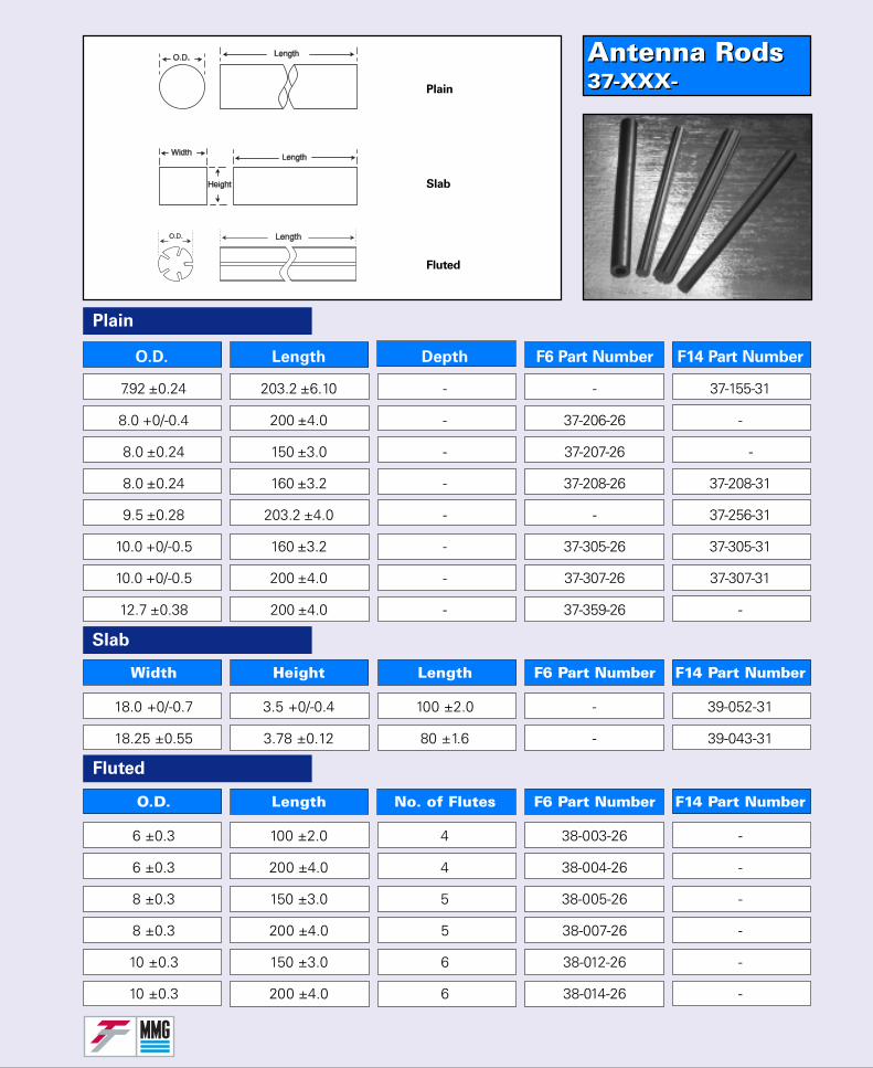
Antenna Rods37-XXX-Antenna Rods37-XXX-
Plain
Slab
Fluted
O.D. Length Depth F6 Part Number F14 Part Number
7.92 ±0.24 203.2 ±6.10 - - 37-155-31
8.0 +0/-0.4 200 ±4.0 - 37-206-26 -
8.0 ±0.24 150 ±3.0 - 37-207-26 -
8.0 ±0.24 160 ±3.2 - 37-208-26 37-208-31
9.5 ±0.28 203.2 ±4.0 - - 37-256-31
10.0 +0/-0.5 160 ±3.2 - 37-305-26 37-305-31
10.0 +0/-0.5 200 ±4.0 - 37-307-26 37-307-31
12.7 ±0.38 200 ±4.0 - 37-359-26 -
18.0 +0/-0.7 3.5 +0/-0.4 100 ±2.0 - 39-052-31
18.25 ±0.55 3.78 ±0.12 80 ±1.6 - 39-043-31
6 ±0.3 100 ±2.0 4 38-003-26 -
6 ±0.3 200 ±4.0 4 38-004-26 -
8 ±0.3 150 ±3.0 5 38-005-26 -
8 ±0.3 200 ±4.0 5 38-007-26 -
10 ±0.3 150 ±3.0 6 38-012-26 -
10 ±0.3 200 ±4.0 6 38-014-26 -
Plain
Slab
Fluted
Width Height Length F6 Part Number F14 Part Number
O.D. Length No. of Flutes F6 Part Number F14 Part Number
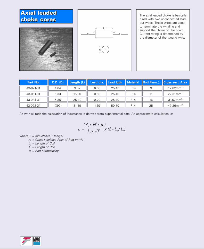
Axial leadedchoke coresAxial leadedchoke cores
As with all rods the calculation of inductance is derived from experimental data. An approximate calculation is:
where:L = Inductance (Henrys)Ar = Cross-sectional Area of Rod (mm2)Lc = Length of CoilLr = Length of Rodµr = Rod permeability
The axial leaded choke is basicallya rod with two unconnected lead-out wires. These wires are usedto terminate the winding andsupport the choke on the board.Current rating is determined bythe diameter of the wound wire.
L = Lr x 109 x (2 - Lc / Lr )( Ar x N2 x µr )
Part No. O.D. (D) Length (L) Lead dia. Lead lgth. Material Rod Perm.(µ) Cross sect. Area
43-021-31 4.04 9.52 0.60 25.40 F14 9 12.82mm2
43-061-31 5.33 15.90 0.60 25.40 F14 11 22.31mm2
43-084-31 6.35 25.40 0.70 25.40 F14 16 31.67mm2
43-092-31 7.92 31.80 1.20 50.80 F14 25 49.26mm2
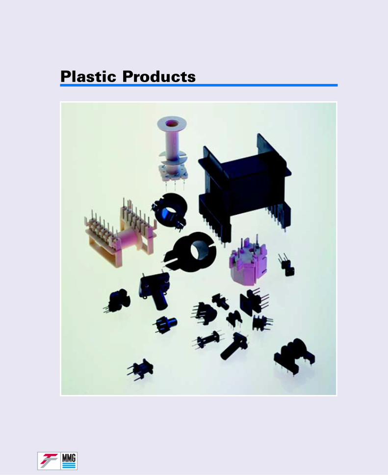
Plastic Products
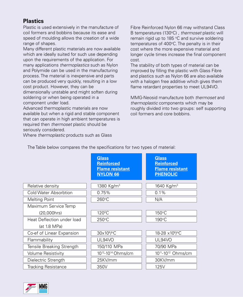
PlasticsPlastic is used extensively in the manufacture ofcoil formers and bobbins because its ease andspeed of moulding allows the creation of a widerange of shapes.Many different plastic materials are now availablewhich are ideally suited for such use dependingupon the requirements of the application. Formany applications thermoplastics such as Nylonand Polymide can be used in the manufacturingprocess. The material is inexpensive and partscan be produced very quickly, resulting in a lowcost product. However, they can bedimensionally unstable and might soften duringsoldering or when being operated in acomponent under load.Advanced thermoplastic materials are nowavailable but when a rigid and stable componentthat can operate in high ambient temperatures isrequired then thermoset plastic should beseriously considered.Where thermoplastic products such as Glass
Fibre Reinforced Nylon 66 may withstand ClassB temperatures (130oC) , thermoset plastic willremain rigid up to 185 oC and survive solderingtemperatures of 400oC. The penalty is in theircost where the more expensive material andlonger cycle times increase the final componentcost.The stability of both types of material can beimproved by filling the plastic with Glass Fibreand plastics such as Nylon 66 are also availablewith a halogen free additive which gives themflame retardant properties to meet UL94VO.
MMG-Neosid manufacture both thermoset andthermoplastic components which may beroughly divided into two groups: self supportingcoil formers and core bobbins.
The Table below compares the the specifications for two types of material:
Glass Glass
Reinforced Reinforced
Flame resistant Flame resistant
NYLON 66 PHENOLIC
Relative density 1380 Kg/m3 1640 Kg/m3
Cold Water Absorbtion 0.75% 0.1%Melting Point 260oC N/AMaximum Service Temp
(20,000hrs) 1200C 150oCHeat Deflection under load 250oC 190oC
(at 1.8 MPa)Co-ef of Linear Expansion 30x106/oC 18-28 x106/oCFlammability UL94VO UL94VOTensile Breaking Strength 150/110 MPa 70/90 MPaVolume Resistivity 1012-1014 Ohms/cm 1011-1012 Ohms/cmDielectric Strength 25KV/mm 30KV/mmTracking Resistance 350V 125V
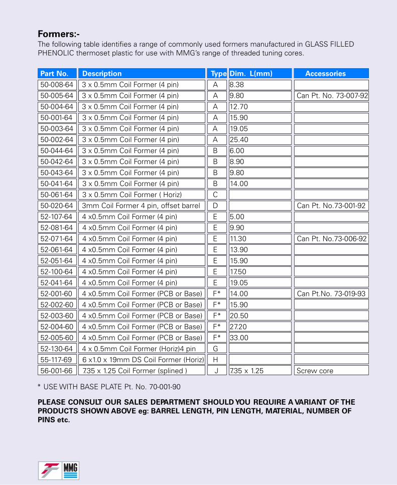
PLEASE CONSULT OUR SALES DEPARTMENT SHOULD YOU REQUIRE A VARIANT OF THE
PRODUCTS SHOWN ABOVE eg: BARREL LENGTH, PIN LENGTH, MATERIAL, NUMBER OF
PINS etc.
* USE WITH BASE PLATE Pt. No. 70-001-90
Formers:-The following table identifies a range of commonly used formers manufactured in GLASS FILLEDPHENOLIC thermoset plastic for use with MMG’s range of threaded tuning cores.
Part No. Description Type Dim. L(mm) Accessories
50-008-64 3 x 0.5mm Coil Former (4 pin) A 8.3850-005-64 3 x 0.5mm Coil Former (4 pin) A 9.80 Can Pt. No. 73-007-9250-004-64 3 x 0.5mm Coil Former (4 pin) A 12.7050-001-64 3 x 0.5mm Coil Former (4 pin) A 15.9050-003-64 3 x 0.5mm Coil Former (4 pin) A 19.0550-002-64 3 x 0.5mm Coil Former (4 pin) A 25.4050-044-64 3 x 0.5mm Coil Former (4 pin) B 6.0050-042-64 3 x 0.5mm Coil Former (4 pin) B 8.9050-043-64 3 x 0.5mm Coil Former (4 pin) B 9.8050-041-64 3 x 0.5mm Coil Former (4 pin) B 14.0050-061-64 3 x 0.5mm Coil Former ( Horiz) C50-020-64 3mm Coil Former 4 pin, offset barrel D Can Pt. No.73-001-9252-107-64 4 x0.5mm Coil Former (4 pin) E 5.0052-081-64 4 x0.5mm Coil Former (4 pin) E 9.9052-071-64 4 x0.5mm Coil Former (4 pin) E 11.30 Can Pt. No.73-006-9252-061-64 4 x0.5mm Coil Former (4 pin) E 13.9052-051-64 4 x0.5mm Coil Former (4 pin) E 15.9052-100-64 4 x0.5mm Coil Former (4 pin) E 17.5052-041-64 4 x0.5mm Coil Former (4 pin) E 19.0552-001-60 4 x0.5mm Coil Former (PCB or Base) F* 14.00 Can Pt.No. 73-019-9352-002-60 4 x0.5mm Coil Former (PCB or Base) F* 15.9052-003-60 4 x0.5mm Coil Former (PCB or Base) F* 20.5052-004-60 4 x0.5mm Coil Former (PCB or Base) F* 27.2052-005-60 4 x0.5mm Coil Former (PCB or Base) F* 33.0052-130-64 4 x 0.5mm Coil Former (Horiz)4 pin G55-117-69 6 x1.0 x 19mm DS Coil Former (Horiz) H56-001-66 7.35 x 1.25 Coil Former (splined ) J 7.35 x 1.25 Screw core
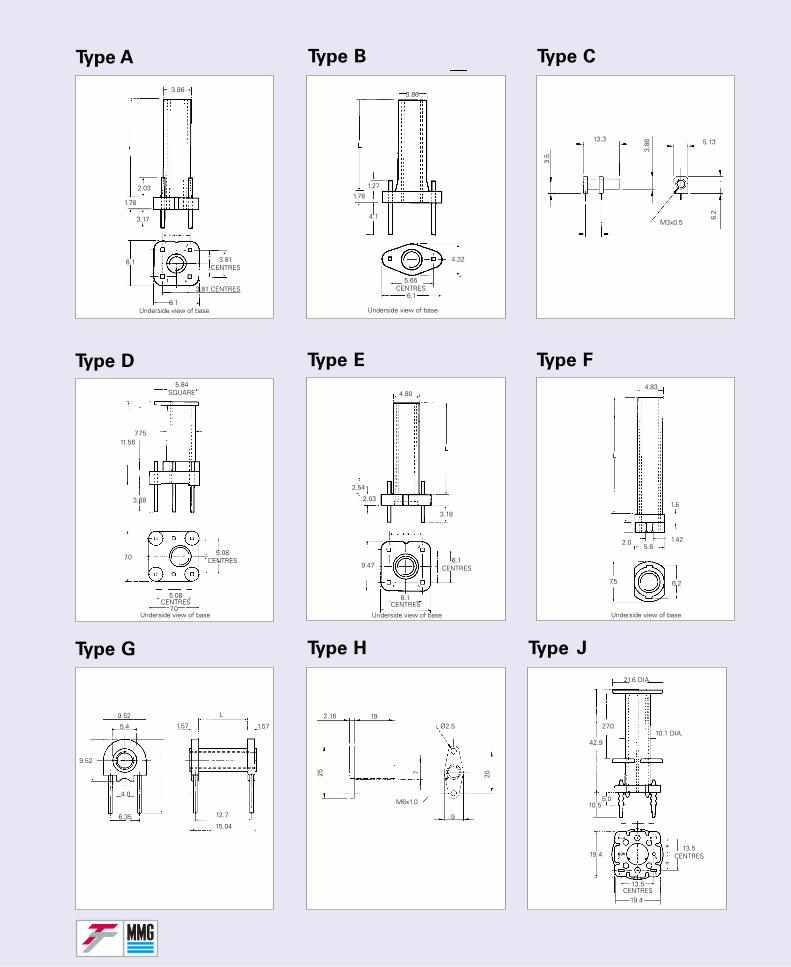
Type A Type B Type C
Type D Type E Type F
Type G Type H
6.1 3.81CENTRES
6.1
3.86
2.03
1.78
3.17
3.81 CENTRES
Underside view of base
3.86
1.27
1.78
4.1
4.32
5.65CENTRES
6.1
Underside view of base
13.3
3.5
3.86 5.13
6.2
M3x0.5
5.84SQUARE
11.567.75
3.68
7.05.08
CENTRES
5.08CENTRES
7.0Underside view of base
4.80
2.54
2.03
3.18
9.476.1
CENTRES
6.1CENTRES
9.47Underside view of base
4.83
1.5
1.422.05.6
7.5 6.2
Underside view of base
9.52
5.4
9.52
4.0
6.35
1.57
L
1.57
12.7
15.04
2.16 19
25 7 20
9
M6x1.0
Ø2.5
Type J
21.6 DIA.
10.1 DIA.
13.5CENTRES19.4
13.5CENTRES
19.4
27.0
42.9
10.55.0
=
=
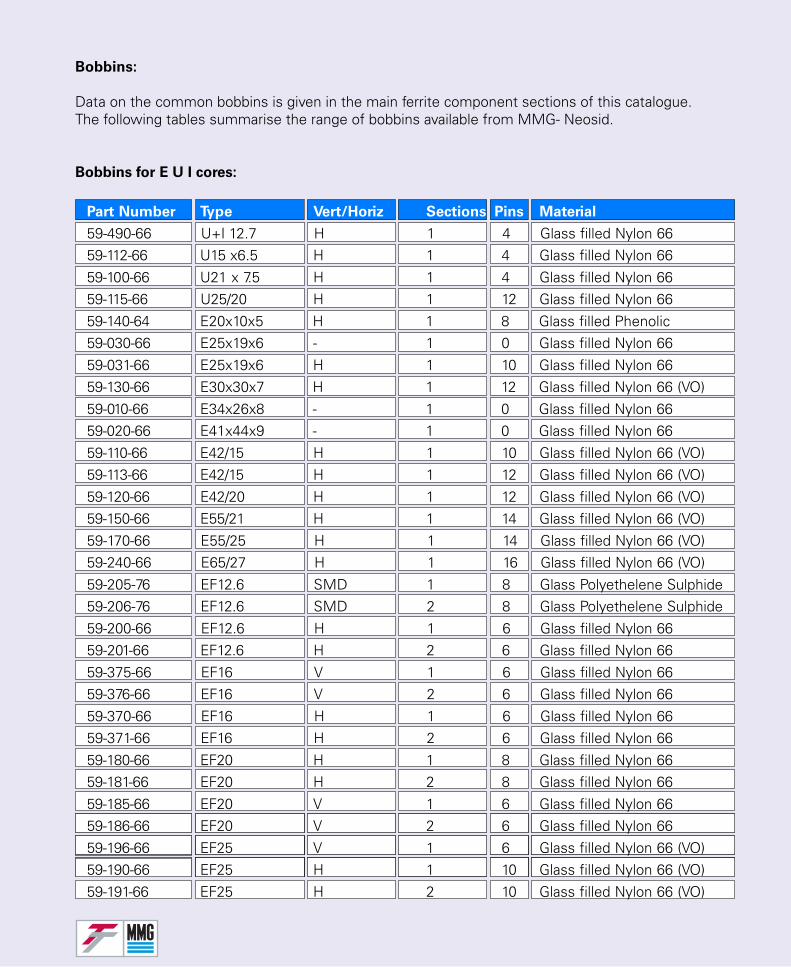
Bobbins:
Data on the common bobbins is given in the main ferrite component sections of this catalogue.The following tables summarise the range of bobbins available from MMG- Neosid.
Bobbins for E U I cores:
Part Number Type Vert/Horiz Sections Pins Material
59-490-66 U+I 12.7 H 1 4 Glass filled Nylon 6659-112-66 U15 x6.5 H 1 4 Glass filled Nylon 6659-100-66 U21 x 7.5 H 1 4 Glass filled Nylon 6659-115-66 U25/20 H 1 12 Glass filled Nylon 6659-140-64 E20x10x5 H 1 8 Glass filled Phenolic59-030-66 E25x19x6 - 1 0 Glass filled Nylon 6659-031-66 E25x19x6 H 1 10 Glass filled Nylon 6659-130-66 E30x30x7 H 1 12 Glass filled Nylon 66 (VO)59-010-66 E34x26x8 - 1 0 Glass filled Nylon 6659-020-66 E41x44x9 - 1 0 Glass filled Nylon 6659-110-66 E42/15 H 1 10 Glass filled Nylon 66 (VO)59-113-66 E42/15 H 1 12 Glass filled Nylon 66 (VO)59-120-66 E42/20 H 1 12 Glass filled Nylon 66 (VO)59-150-66 E55/21 H 1 14 Glass filled Nylon 66 (VO)59-170-66 E55/25 H 1 14 Glass filled Nylon 66 (VO)59-240-66 E65/27 H 1 16 Glass filled Nylon 66 (VO)59-205-76 EF12.6 SMD 1 8 Glass Polyethelene Sulphide59-206-76 EF12.6 SMD 2 8 Glass Polyethelene Sulphide59-200-66 EF12.6 H 1 6 Glass filled Nylon 6659-201-66 EF12.6 H 2 6 Glass filled Nylon 6659-375-66 EF16 V 1 6 Glass filled Nylon 6659-376-66 EF16 V 2 6 Glass filled Nylon 6659-370-66 EF16 H 1 6 Glass filled Nylon 6659-371-66 EF16 H 2 6 Glass filled Nylon 6659-180-66 EF20 H 1 8 Glass filled Nylon 6659-181-66 EF20 H 2 8 Glass filled Nylon 6659-185-66 EF20 V 1 6 Glass filled Nylon 6659-186-66 EF20 V 2 6 Glass filled Nylon 6659-196-66 EF25 V 1 6 Glass filled Nylon 66 (VO)59-190-66 EF25 H 1 10 Glass filled Nylon 66 (VO)59-191-66 EF25 H 2 10 Glass filled Nylon 66 (VO)
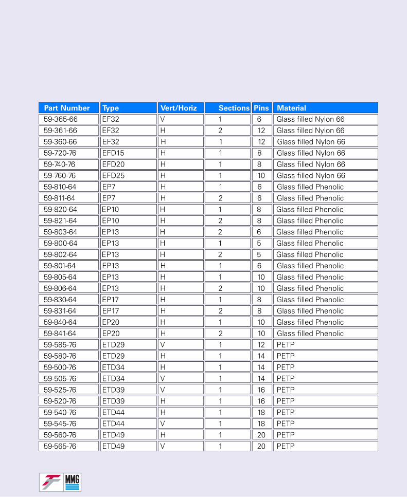
Part Number Type Vert/Horiz Sections Pins Material
59-365-66 EF32 V 1 6 Glass filled Nylon 6659-361-66 EF32 H 2 12 Glass filled Nylon 6659-360-66 EF32 H 1 12 Glass filled Nylon 6659-720-76 EFD15 H 1 8 Glass filled Nylon 6659-740-76 EFD20 H 1 8 Glass filled Nylon 6659-760-76 EFD25 H 1 10 Glass filled Nylon 6659-810-64 EP7 H 1 6 Glass filled Phenolic59-811-64 EP7 H 2 6 Glass filled Phenolic59-820-64 EP10 H 1 8 Glass filled Phenolic59-821-64 EP10 H 2 8 Glass filled Phenolic59-803-64 EP13 H 2 6 Glass filled Phenolic59-800-64 EP13 H 1 5 Glass filled Phenolic59-802-64 EP13 H 2 5 Glass filled Phenolic59-801-64 EP13 H 1 6 Glass filled Phenolic59-805-64 EP13 H 1 10 Glass filled Phenolic59-806-64 EP13 H 2 10 Glass filled Phenolic59-830-64 EP17 H 1 8 Glass filled Phenolic59-831-64 EP17 H 2 8 Glass filled Phenolic59-840-64 EP20 H 1 10 Glass filled Phenolic59-841-64 EP20 H 2 10 Glass filled Phenolic59-585-76 ETD29 V 1 12 PETP59-580-76 ETD29 H 1 14 PETP59-500-76 ETD34 H 1 14 PETP59-505-76 ETD34 V 1 14 PETP59-525-76 ETD39 V 1 16 PETP59-520-76 ETD39 H 1 16 PETP59-540-76 ETD44 H 1 18 PETP59-545-76 ETD44 V 1 18 PETP59-560-76 ETD49 H 1 20 PETP59-565-76 ETD49 V 1 20 PETP
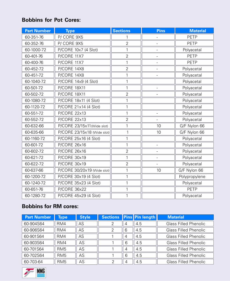
Bobbins for Pot Cores:
Bobbins for RM cores:
Part Number Type Style Sections Pins Pin length Material
Part Number Type Sections Pins Material
60-351-76 P/ CORE 9X5 1 - PETP60-352-76 P/ CORE 9X5 2 - PETP60-1000-72 P/CORE 10x7 (4 Slot) 1 - Polyacetal60-401-76 P/CORE 11X7 2 - PETP60-400-76 P/CORE 11X7 1 - PETP60-452-72 P/CORE 14X8 2 - Polyacetal60-451-72 P/CORE 14X8 1 - Polyacetal60-1040-72 P/CORE 14x9 (4 Slot) 1 Polyacetal60-501-72 P/CORE 18X11 1 - Polyacetal60-502-72 P/CORE 18X11 2 - Polyacetal60-1080-72 P/CORE 18x11 (4 Slot) 1 Polyacetal60-1120-72 P/CORE 21x14 (4 Slot) 1 Polyacetal60-551-72 P/CORE 22x13 1 - Polyacetal60-552-72 P/CORE 22x13 2 - Polyacetal60-632-66 P/CORE 23/15x11(Wide slot) 1 10 G/F Nylon 6660-635-66 P/CORE 23/15x18 (Wide slot) 1 10 G/F Nylon 6660-1160-72 P/CORE 25x16 (4 Slot) 1 Polyacetal60-601-72 P/CORE 26x16 1 - Polyacetal60-602-72 P/CORE 26x16 2 - Polyacetal60-621-72 P/CORE 30x19 1 - Polyacetal60-622-72 P/CORE 30x19 2 - Polyacetal60-637-66 P/CORE 30/20x19 (Wide slot) 1 10 G/F Nylon 6660-1200-72 P/CORE 30x19 (4 Slot) 1 Polypropylene60-1240-72 P/CORE 35x23 (4 Slot) 1 Polyacetal60-651-76 P/CORE 36x22 1 PETP60-1280-72 P/CORE 45x29 (4 Slot) 1 Polyacetal
60-904S64 RM4 AS 2 4 4.5 Glass Filled Phenolic60-906S64 RM4 AS 2 6 4.5 Glass Filled Phenolic60-901S64 RM4 AS 1 4 4.5 Glass Filled Phenolic60-903S64 RM4 AS 1 6 4.5 Glass Filled Phenolic60-701S64 RM5 AS 1 4 4.5 Glass Filled Phenolic60-702S64 RM5 AS 1 6 4.5 Glass Filled Phenolic60-703-64 RM5 AS 2 4 4.5 Glass Filled Phenolic
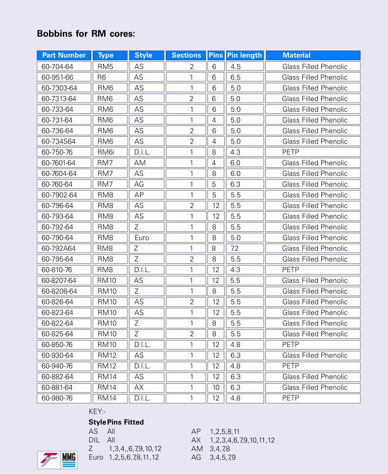
Bobbins for RM cores:
Part Number Type Style Sections Pins Pin length Material
KEY:-StylePins Fitted
AS AllDIL AllZ 1,3,4,,6,7,9,10,12Euro 1,2,5,6,7,8,11,12
AP 1,2,5,8,11AX 1,2,3,4,6,7,9,10,11,12AM 3,4,7,8AG 3,4,5,7,9
60-704-64 RM5 AS 2 6 4.5 Glass Filled Phenolic60-951-66 R6 AS 1 6 6.5 Glass Filled Phenolic60-7303-64 RM6 AS 1 6 5.0 Glass Filled Phenolic60-7313-64 RM6 AS 2 6 5.0 Glass Filled Phenolic60-733-64 RM6 AS 1 6 5.0 Glass Filled Phenolic60-731-64 RM6 AS 1 4 5.0 Glass Filled Phenolic60-736-64 RM6 AS 2 6 5.0 Glass Filled Phenolic60-734S64 RM6 AS 2 4 5.0 Glass Filled Phenolic60-750-76 RM6i D.I.L. 1 8 4.3 PETP60-7601-64 RM7 AM 1 4 6.0 Glass Filled Phenolic60-7604-64 RM7 AS 1 8 6.0 Glass Filled Phenolic60-760-64 RM7 AG 1 5 6.3 Glass Filled Phenolic60-7902-64 RM8 AP 1 5 5.5 Glass Filled Phenolic60-796-64 RM8 AS 2 12 5.5 Glass Filled Phenolic60-793-64 RM8 AS 1 12 5.5 Glass Filled Phenolic60-792-64 RM8 Z 1 8 5.5 Glass Filled Phenolic60-790-64 RM8 Euro 1 8 5.0 Glass Filled Phenolic60-792A64 RM8 Z 1 8 7.2 Glass Filled Phenolic60-795-64 RM8 Z 2 8 5.5 Glass Filled Phenolic60-810-76 RM8 D.I.L. 1 12 4.3 PETP60-8207-64 RM10 AS 1 12 5.5 Glass Filled Phenolic60-8208-64 RM10 Z 1 8 5.5 Glass Filled Phenolic60-826-64 RM10 AS 2 12 5.5 Glass Filled Phenolic60-823-64 RM10 AS 1 12 5.5 Glass Filled Phenolic60-822-64 RM10 Z 1 8 5.5 Glass Filled Phenolic60-825-64 RM10 Z 2 8 5.5 Glass Filled Phenolic60-850-76 RM10 D.I.L. 1 12 4.8 PETP60-930-64 RM12 AS 1 12 6.3 Glass Filled Phenolic60-940-76 RM12 D.I.L. 1 12 4.8 PETP60-882-64 RM14 AS 1 12 6.3 Glass Filled Phenolic60-881-64 RM14 AX 1 10 6.3 Glass Filled Phenolic60-980-76 RM14 D.I.L. 1 12 4.8 PETP
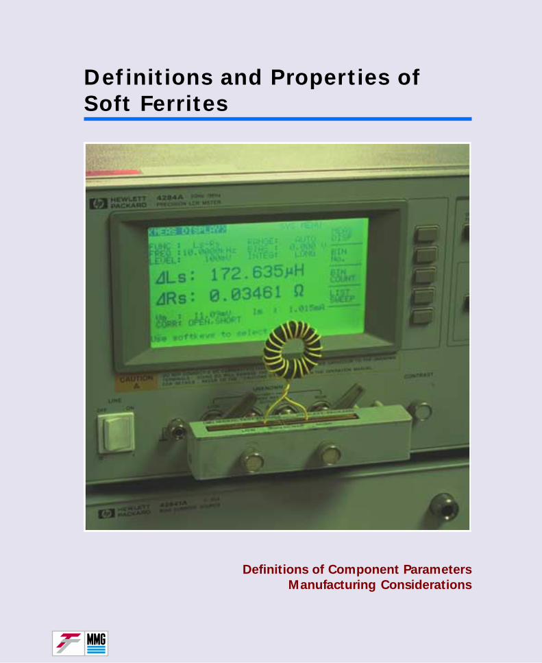
Definitions and Properties ofSoft Ferrites
Definitions of Component Parameters
Manufacturing Considerations
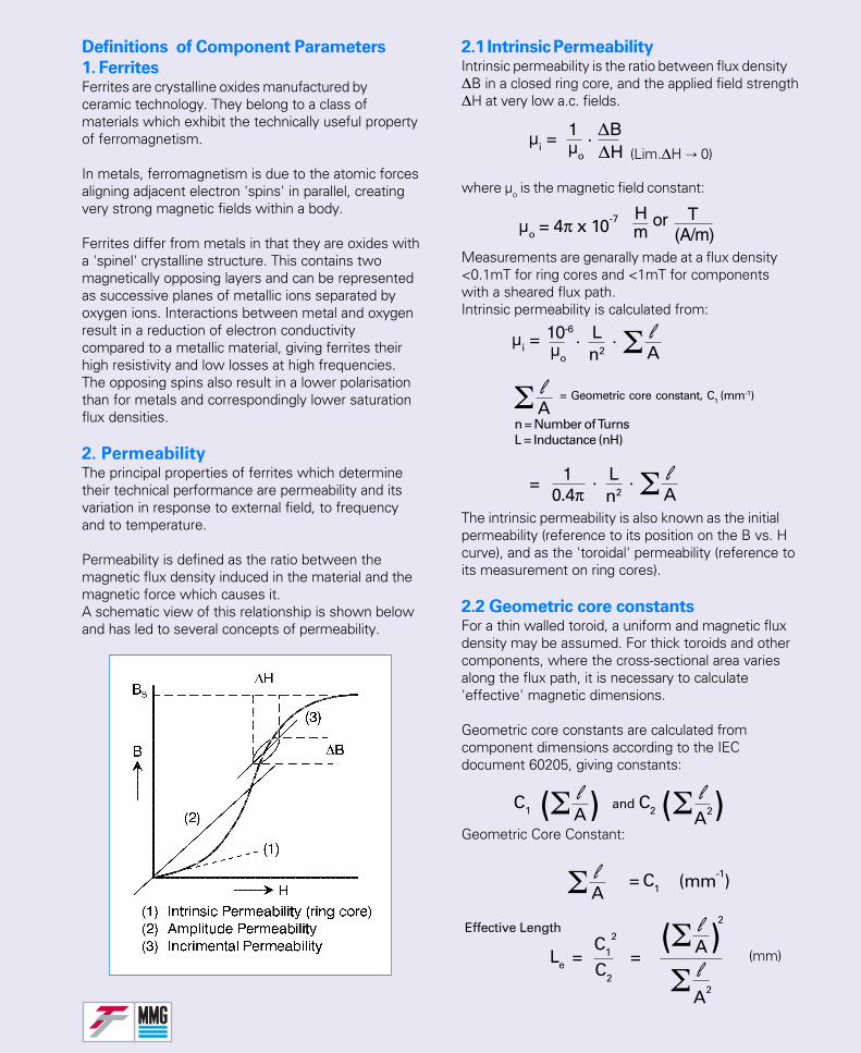
2.1 Intrinsic PermeabilityIntrinsic permeability is the ratio between flux density∆B in a closed ring core, and the applied field strength∆H at very low a.c. fields.
where µo is the magnetic field constant:
Measurements are genarally made at a flux density<0.1mT for ring cores and <1mT for componentswith a sheared flux path.Intrinsic permeability is calculated from:
The intrinsic permeability is also known as the initialpermeability (reference to its position on the B vs. Hcurve), and as the 'toroidal' permeability (reference toits measurement on ring cores).
2.2 Geometric core constantsFor a thin walled toroid, a uniform and magnetic fluxdensity may be assumed. For thick toroids and othercomponents, where the cross-sectional area variesalong the flux path, it is necessary to calculate'effective' magnetic dimensions.
Geometric core constants are calculated fromcomponent dimensions according to the IECdocument 60205, giving constants:
Geometric Core Constant:
(mm)
Definitions of Component Parameters
1. FerritesFerrites are crystalline oxides manufactured byceramic technology. They belong to a class ofmaterials which exhibit the technically useful propertyof ferromagnetism.
In metals, ferromagnetism is due to the atomic forcesaligning adjacent electron 'spins' in parallel, creatingvery strong magnetic fields within a body.
Ferrites differ from metals in that they are oxides witha 'spinel' crystalline structure. This contains twomagnetically opposing layers and can be representedas successive planes of metallic ions separated byoxygen ions. Interactions between metal and oxygenresult in a reduction of electron conductivitycompared to a metallic material, giving ferrites theirhigh resistivity and low losses at high frequencies.The opposing spins also result in a lower polarisationthan for metals and correspondingly lower saturationflux densities.
2. PermeabilityThe principal properties of ferrites which determinetheir technical performance are permeability and itsvariation in response to external field, to frequencyand to temperature.
Permeability is defined as the ratio between themagnetic flux density induced in the material and themagnetic force which causes it.A schematic view of this relationship is shown belowand has led to several concepts of permeability.
µi =1µo
∆B∆H (Lim.∆H 0)
.
µo = 4π x 10-7 Hm
or T(A/m)
µi =10-6
µo
. Ln2
. lAΣ
lAΣ = Geometric core constant, C1 (mm-1)
n = Number of TurnsL = Inductance (nH)
. Ln2
. lAΣ0.4π
1=
lΣ lA2ΣC1 and C2( ) ( )
lAΣ = C1 (mm-1)
C1
2
C2
Le = =
A
lΣ( )A
2Effective Length
lΣA2
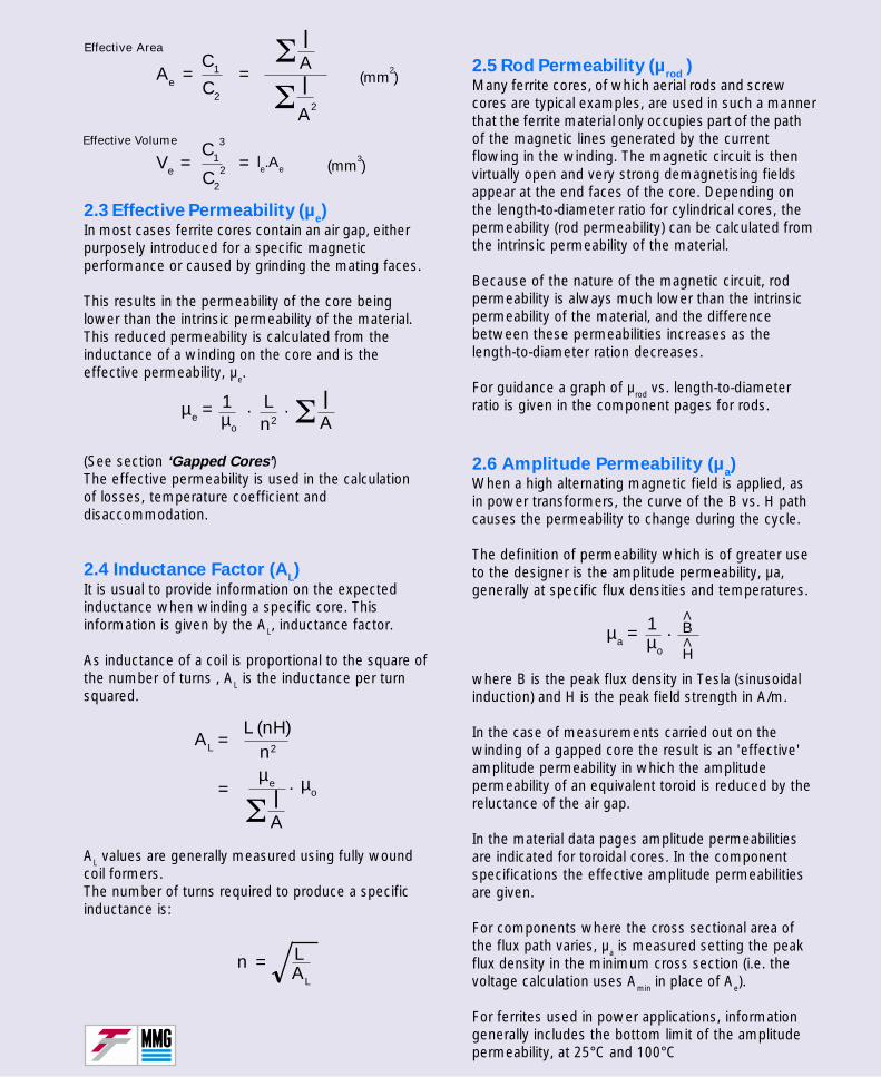
2.3 Effective Permeability (µe)
In most cases ferrite cores contain an air gap, eitherpurposely introduced for a specific magneticperformance or caused by grinding the mating faces.
This results in the permeability of the core beinglower than the intrinsic permeability of the material.This reduced permeability is calculated from theinductance of a winding on the core and is theeffective permeability, µe.
(See section ‘Gapped Cores’)The effective permeability is used in the calculationof losses, temperature coefficient anddisaccommodation.
2.4 Inductance Factor (AL)
It is usual to provide information on the expectedinductance when winding a specific core. Thisinformation is given by the AL, inductance factor.
As inductance of a coil is proportional to the square ofthe number of turns , AL is the inductance per turnsquared.
AL values are generally measured using fully woundcoil formers.The number of turns required to produce a specificinductance is:
2.5 Rod Permeability (µrod
)Many ferrite cores, of which aerial rods and screwcores are typical examples, are used in such a mannerthat the ferrite material only occupies part of the pathof the magnetic lines generated by the currentflowing in the winding. The magnetic circuit is thenvirtually open and very strong demagnetising fieldsappear at the end faces of the core. Depending onthe length-to-diameter ratio for cylindrical cores, thepermeability (rod permeability) can be calculated fromthe intrinsic permeability of the material.
Because of the nature of the magnetic circuit, rodpermeability is always much lower than the intrinsicpermeability of the material, and the differencebetween these permeabilities increases as thelength-to-diameter ration decreases.
For guidance a graph of µrod vs. length-to-diameterratio is given in the component pages for rods.
2.6 Amplitude Permeability (µa)
When a high alternating magnetic field is applied, asin power transformers, the curve of the B vs. H pathcauses the permeability to change during the cycle.
The definition of permeability which is of greater useto the designer is the amplitude permeability, µa,generally at specific flux densities and temperatures.
where B is the peak flux density in Tesla (sinusoidalinduction) and H is the peak field strength in A/m.
In the case of measurements carried out on thewinding of a gapped core the result is an 'effective'amplitude permeability in which the amplitudepermeability of an equivalent toroid is reduced by thereluctance of the air gap.
In the material data pages amplitude permeabilitiesare indicated for toroidal cores. In the componentspecifications the effective amplitude permeabilitiesare given.
For components where the cross sectional area ofthe flux path varies, µa is measured setting the peakflux density in the minimum cross section (i.e. thevoltage calculation uses Amin in place of Ae).
For ferrites used in power applications, informationgenerally includes the bottom limit of the amplitudepermeability, at 25°C and 100°C
C1
3
C2
2Ve = =
lΣAlΣA2
Effective Area
Effective Volume
(mm2)
(mm3)le.Ae
C1
C2
Ae = =
µe =1µo
. Ln2
. lAΣ
lAΣ
µo=
AL
µe
=
.
L (nH)n2
n = LAL
µa =1µo
B
H
.∧
∧
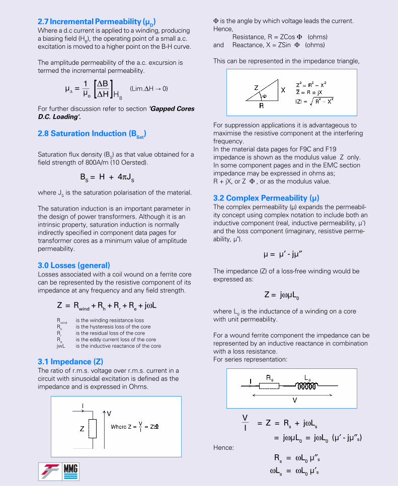
2.7 Incremental Permeability (µD)
Where a d.c current is applied to a winding, producinga biasing field (HB), the operating point of a small a.c.excitation is moved to a higher point on the B-H curve.
The amplitude permeability of the a.c. excursion istermed the incremental permeability.
For further discussion refer to section 'Gapped Cores
D.C. Loading'.
2.8 Saturation Induction (BSat
)
Saturation flux density (BS) as that value obtained for afield strength of 800A/m (10 Oersted).
where JS is the saturation polarisation of the material.
The saturation induction is an important parameter inthe design of power transformers. Although it is anintrinsic property, saturation induction is normallyindirectly specified in component data pages fortransformer cores as a minimum value of amplitudepermeability.
3.0 Losses (general)Losses associated with a coil wound on a ferrite corecan be represented by the resistive component of itsimpedance at any frequency and any field strength.
Rwind is the winding resistance lossRh is the hysteresis loss of the coreRr is the residual loss of the coreRe is the eddy current loss of the corejwL is the inductive reactance of the core
3.1 Impedance (Z)The ratio of r.m.s. voltage over r.m.s. current in acircuit with sinusoidal excitation is defined as theimpedance and is expressed in Ohms.
Φ is the angle by which voltage leads the current.Hence,
Resistance, R = ZCos Φ (ohms)and Reactance, X = ZSin Φ (ohms)
This can be represented in the impedance triangle,
For suppression applications it is advantageous tomaximise the resistive component at the interferingfrequency.In the material data pages for F9C and F19impedance is shown as the modulus value Z only.In some component pages and in the EMC sectionimpedance may be expressed in ohms as;R + jX, or Z Φ , or as the modulus value.
3.2 Complex Permeability (µ)The complex permeability (µ) expands the permeabil-ity concept using complex notation to include both aninductive component (real, inductive permeability, µ')and the loss component (imaginary, resistive perme-ability, µ").
The impedance (Z) of a loss-free winding would beexpressed as:
where L0 is the inductance of a winding on a corewith unit permeability.
For a wound ferrite component the impedance can berepresented by an inductive reactance in combinationwith a loss resistance.For series representation:
Hence:
µ∆ = 1
µo
∆B∆H HB
(Lim.∆H 0)][
BS = H + 4πJS
Z = Rwind + Rh + Rr + Re + jωL
µ = µ′ - jµ″
Z = jωµL0
= Z = Rs + jωLs
VI
= jωµL0 = jωL0 (µ′ - jµ″s)
Rs = ωL0 µ″s
ωLs = ωL0 µ′s
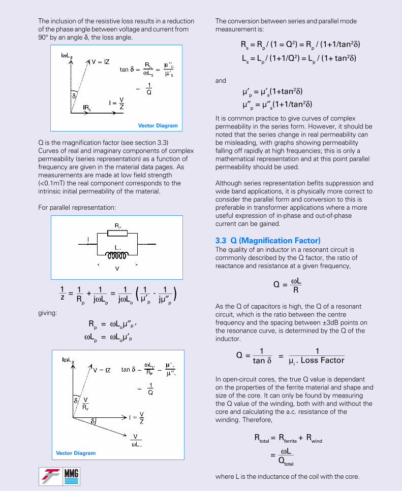
The inclusion of the resistive loss results in a reductionof the phase angle between voltage and current from90° by an angle δ, the loss angle.
Q is the magnification factor (see section 3.3)Curves of real and imaginary components of complexpermeability (series representation) as a function offrequency are given in the material data pages. Asmeasurements are made at low field strength(<0.1mT) the real component corresponds to theintrinsic initial permeability of the material.
For parallel representation:
giving:
The conversion between series and parallel modemeasurement is:
and
It is common practice to give curves of complexpermeability in the series form. However, it should benoted that the series change in real permeability canbe misleading, with graphs showing permeabilityfalling off rapidly at high frequencies; this is only amathematical representation and at this point parallelpermeability should be used.
Although series representation befits suppression andwide band applications, it is physically more correct toconsider the parallel form and conversion to this ispreferable in transformer applications where a moreuseful expression of in-phase and out-of-phasecurrent can be gained.
3.3 Q (Magnification Factor)The quality of an inductor in a resonant circuit iscommonly described by the Q factor, the ratio ofreactance and resistance at a given frequency,
As the Q of capacitors is high, the Q of a resonantcircuit, which is the ratio between the centrefrequency and the spacing between ±3dB points onthe resonance curve, is determined by the Q of theinductor.
In open-circuit cores, the true Q value is dependanton the properties of the ferrite material and shape andsize of the core. It can only be found by measuringthe Q value of the winding, both with and without thecore and calculating the a.c. resistance of thewinding. Therefore,
where L is the inductance of the coil with the core.
Vector Diagram
Vector Diagram
1z = 1
Rp
+ 1jωLp
= 1jωLo
( )1 -µ′p
1jµ″p
Rp = ωLoµ″p ,
ωLp = ωLoµ′p
Rs = Rp / (1 = Q2) = Rp / (1+1/tan2δ)
Ls = Lp / (1+1/Q2) = Lp / (1+ tan2δ)
µ′p = µ′s(1+tan2δ)
µ″p = µ″s(1+1/tan2δ)
ωLR
=Q
1=Qtan δ = 1
µi . Loss Factor
ωLQtotal
=
Rtotal = Rferrite + Rwind
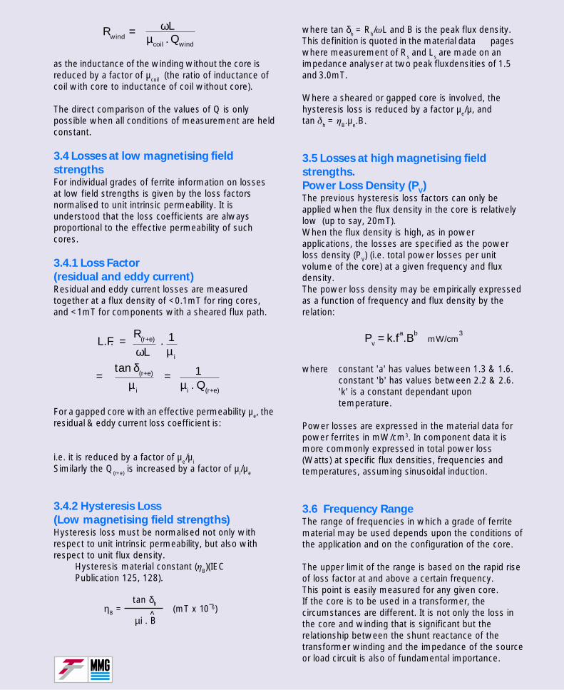
as the inductance of the winding without the core isreduced by a factor of µcoil (the ratio of inductance ofcoil with core to inductance of coil without core).
The direct comparison of the values of Q is onlypossible when all conditions of measurement are heldconstant.
3.4 Losses at low magnetising field
strengthsFor individual grades of ferrite information on lossesat low field strengths is given by the loss factorsnormalised to unit intrinsic permeability. It isunderstood that the loss coefficients are alwaysproportional to the effective permeability of suchcores.
3.4.1 Loss Factor
(residual and eddy current)Residual and eddy current losses are measuredtogether at a flux density of <0.1mT for ring cores,and <1mT for components with a sheared flux path.
For a gapped core with an effective permeability µe, theresidual & eddy current loss coefficient is:
i.e. it is reduced by a factor of µe/µiSimilarly the Q(r+e) is increased by a factor of µi/µe
3.4.2 Hysteresis Loss
(Low magnetising field strengths)Hysteresis loss must be normalised not only withrespect to unit intrinsic permeability, but also withrespect to unit flux density.
Hysteresis material constant (ηB)(IECPublication 125, 128).
where tan δh = Rh/ωL and B is the peak flux density.This definition is quoted in the material data pageswhere measurement of Rs and Ls are made on animpedance analyser at two peak fluxdensities of 1.5and 3.0mT.
Where a sheared or gapped core is involved, thehysteresis loss is reduced by a factor µe/µ, andtan δh = ηB.µe.B.
3.5 Losses at high magnetising field
strengths.
Power Loss Density (PV)
The previous hysteresis loss factors can only beapplied when the flux density in the core is relativelylow (up to say, 20mT).When the flux density is high, as in powerapplications, the losses are specified as the powerloss density (PV) (i.e. total power losses per unitvolume of the core) at a given frequency and fluxdensity.The power loss density may be empirically expressedas a function of frequency and flux density by therelation:
where constant 'a' has values between 1.3 & 1.6.constant 'b' has values between 2.2 & 2.6.'k' is a constant dependant upontemperature.
Power losses are expressed in the material data forpower ferrites in mW/cm3. In component data it ismore commonly expressed in total power loss(Watts) at specific flux densities, frequencies andtemperatures, assuming sinusoidal induction.
3.6 Frequency RangeThe range of frequencies in which a grade of ferritematerial may be used depends upon the conditions ofthe application and on the configuration of the core.
The upper limit of the range is based on the rapid riseof loss factor at and above a certain frequency.This point is easily measured for any given core.If the core is to be used in a transformer, thecircumstances are different. It is not only the loss inthe core and winding that is significant but therelationship between the shunt reactance of thetransformer winding and the impedance of the sourceor load circuit is also of fundamental importance.
ηB = (mT x 10¯6)tan δh
µi . B^
ωLµcoil . Qwind
Rwind =
L.F. =R(r+e)
ωL. 1µi
1µi . Q(r+e)
=tan δ(r+e)
µi
=
Pv = k.fa.Bb mW/cm3
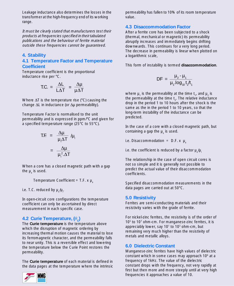
Leakage inductance also determines the losses in thetransformer at the high-frequency end of its workingrange.
It must be clearly stated that manufacturers test theirproducts at frequencies specified in their tabulatedpublications and the behaviour of ferrite materialoutside these frequencies cannot be guaranteed.
4. Stability
4.1 Temperature Factor and Temperature
CoefficientTemperature coefficient is the proportionalinductance rise per °C.
Where ∆T is the temperature rise (°C) causing thechange ∆L in inductance (or ∆µ permeability).
Temperature Factor is normalised to the unitpermeability and is expressed in ppm/°C and given fora specified temperature range (25°C to 55°C).
When a core has a closed magnetic path with a gapthe µe is used.
Temperature Coefficient = T.F. x µe
i.e. T.C. reduced by µe/µi.
In open-circuit core configurations the temperaturecoefficient can only be ascertained by directmeasurement in each specific case.
4.2 Curie Temperature, (θC)
The Curie temperature is the temperature abovewhich the disruption of magnetic ordering byincreasing thermal motion causes the material to loseits ferromagnetic character, and the permeability fallsto near unity. This is a reversible effect and loweringthe temperature below the Curie Point restores thepermeability.
The Curie temperature of each material is defined inthe data pages at the temperature where the intrinsic
permeability has fallen to 10% of its room temperaturevalue.
4.3 Disaccommodation FactorAfter a ferrite core has been subjected to a shock(thermal, mechanical or magnetic) its permeabilityabruptly increases and immediately begins driftingdownwards. This continues for a very long period.The decrease in permeability is linear when plotted ona logarithmic scale,
This form of instability is termed disaccommodation.
where µ1 is the permeability at the time t1, and µ2 isthe permeability at the time t2. The relative inductancedrop in the period 1 to 10 hours after the shock is thesame as the in the period 1 to 10 years, so that thelong-term instability of the inductance can bepredicted.
In the case of a core with a closed magnetic path, butcontaining a gap the µe is used.
i.e. Disaccommodation = D.F. x µe
i.e. the coefficient is reduced by a factor µe/µi
The relationship in the case of open circuit cores isnot so simple and it is generally not possible topredict the actual value of their disaccommodationcoefficients.
Specified disaccommodation measurements in thedata pages are carried out at 50°C.
5.0 ResistivityFerrites are semi-conducting materials and theirresistivity varies with the grade of ferrite.
For nickel-zinc ferrites, the resistivity is of the order of105 to 107 ohm-cm. For manganese-zinc ferrites, it isappreciably lower, say 101 to 103 ohm-cm, butremaining very much higher than the resistivity ofmetals and metallic alloys.
6.0 Dielectric ConstantManganese-zinc ferrites have high values of dielectricconstant which in some cases may approach 106 at afrequency of 1kHz. The value of the dielectricconstant drops with the frequency, not very rapidly atfirst but then more and more steeply until at very highfrequencies it approaches a value of 10.
T.C. =∆L
L∆T=
∆µµ∆T
T.F. = ∆µµi∆T
/µi
∆µµi
2.∆T=
DF =µ2 - µ1
µ1.log10 t2/t1
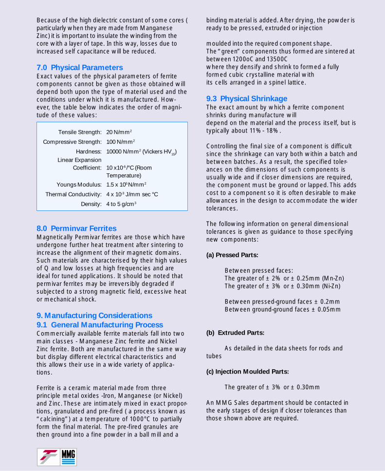
binding material is added. After drying, the powder isready to be pressed, extruded or injection
moulded into the required component shape.The “green” components thus formed are sintered atbetween 1200oC and 13500Cwhere they densify and shrink to formed a fullyformed cubic crystalline material withits cells arranged in a spinel lattice.
9.3 Physical ShrinkageThe exact amount by which a ferrite componentshrinks during manufacture willdepend on the material and the process itself, but istypically about 11%- 18%.
Controlling the final size of a component is difficultsince the shrinkage can vary both within a batch andbetween batches. As a result, the specified toler-ances on the dimensions of such components isusually wide and if closer dimensions are required,the component must be ground or lapped. This addscost to a component so it is often desirable to makeallowances in the design to accommodate the widertolerances.
The following information on general dimensionaltolerances is given as guidance to those specifyingnew components:
(a) Pressed Parts:
Between pressed faces:The greater of ± 2% or ± 0.25mm (Mn-Zn)The greater of ± 3% or ± 0.30mm (Ni-Zn)
Between pressed-ground faces ± 0.2mmBetween ground-ground faces ± 0.05mm
(b) Extruded Parts:
As detailed in the data sheets for rods andtubes
(c) Injection Moulded Parts:
The greater of ± 3% or ± 0.30mm
An MMG Sales department should be contacted inthe early stages of design if closer tolerances thanthose shown above are required.
Because of the high dielectric constant of some cores (particularly when they are made from ManganeseZinc) it is important to insulate the winding from thecore with a layer of tape. In this way, losses due toincreased self capacitance will be reduced.
7.0 Physical ParametersExact values of the physical parameters of ferritecomponents cannot be given as those obtained willdepend both upon the type of material used and theconditions under which it is manufactured. How-ever, the table below indicates the order of magni-tude of these values:
Tensile Strength: 20 N/mm2
Compressive Strength: 100 N/mm2
Hardness: 10000 N/mm2 (Vickers HV15)Linear Expansion
Coefficient: 10 x10-6 /°C (RoomTemperature)
Youngs Modulus: 1.5 x 10⁵ N/mm2
Thermal Conductivity: 4 x 10⁻³ J/mm sec °C
Density: 4 to 5 g/cm3
8.0 Perminvar FerritesMagnetically Permivar ferrites are those which haveundergone further heat treatment after sintering toincrease the alignment of their magnetic domains.Such materials are characterised by their high valuesof Q and low losses at high frequencies and areideal for tuned applications. It should be noted thatpermivar ferrites may be irreversibly degraded ifsubjected to a strong magnetic field, excessive heator mechanical shock.
9. Manufacturing Considerations
9.1 General Manufacturing ProcessCommercially available ferrite materials fall into twomain classes - Manganese Zinc ferrite and NickelZinc ferrite. Both are manufactured in the same waybut display different electrical characteristics andthis allows their use in a wide variety of applica-tions.
Ferrite is a ceramic material made from threeprinciple metal oxides -Iron, Manganese (or Nickel)and Zinc. These are intimately mixed in exact propor-tions, granulated and pre-fired ( a process known as“calcining”) at a temperature of 1000°C to partiallyform the final material. The pre-fired granules arethen ground into a fine powder in a ball mill and a

10.0 Effects of Mechanical StressingWhen a ferrite component is physically stressed itundergoes changes in its electrical characteristics.Compression beyond an ill defined limit causes adecrease in effective permeability at low fluxdensities and an increase in the losses - an effectwhich is also seen in metal alloy cores if there arestamped or spirally wound.
Unfortunately, ferrite components can be stressed bythree commonly used practices:
1. During the grinding of their surfaces
2. Whilst they are being clamped together as acomplete core
3. When they are being encapsulated in asynthetic resin as an insulating coating
During the grinding of polycrystalline ferrites,stresses are applied to the surface and underlyinglayers which lead to the permanent deformation ofthe structure.However, it is possible to grind until a perfect, stress-free finish is obtained but economical factorsgenerally prohibit this in all but the manufacture ofspecialist, high permeability components.
Clamping a pair of cores is another process whichcan induce enough stress to impair the performanceof the core assembly. If the clamping is relativelylight and the applied force is directed along the axisof the mating cores, the effect can be beneficial withthe permeability increased and the losses reduced.However, if the clamping force is great, subjectingthe mating surfaces to high stress levels, theelectromagnetic characteristics will be degraded andstructural damage ( cracking ) may occur in thepolycrystalline structure of the ferrite .
The third and most common cause of stress infinished ferrite components ( particularly toroids) iswhen they are encapsulated in either an epoxy ornylon coating. The ferrite is heated, either when thecoating is applied or afterwards and when both cool,the difference in the thermal coefficients of expansionof the ferrite and the coating, produces stresses inthe ferrite which may reduce its permeability by asmuch as 20%.This effect is reduced if components are coated inwet epoxy or enclosed in plastic caps but theseprocesses are expensive and are generally reservedfor higher permeability toroids.
Alternatively, the shrinkage of compounds used forpotting may be reduced by adding an inorganicmaterial such as silica or glass fibre to the coatingmaterial.
The shape of the hysteresis loop is changed by anycompression to the core; if the magnetostriction ( asmall change in the dimension parallel to thedirection of the applied field) is negative, as with Ni-Zn ferrites, the loop becomes more square. If themagnetostriction is positive, the loop becomes lesssquare.
Finally, if a core is gapped, all effects of stressingare greatly diminished ( unless the stress effectsthe actual length of the gap itself! )
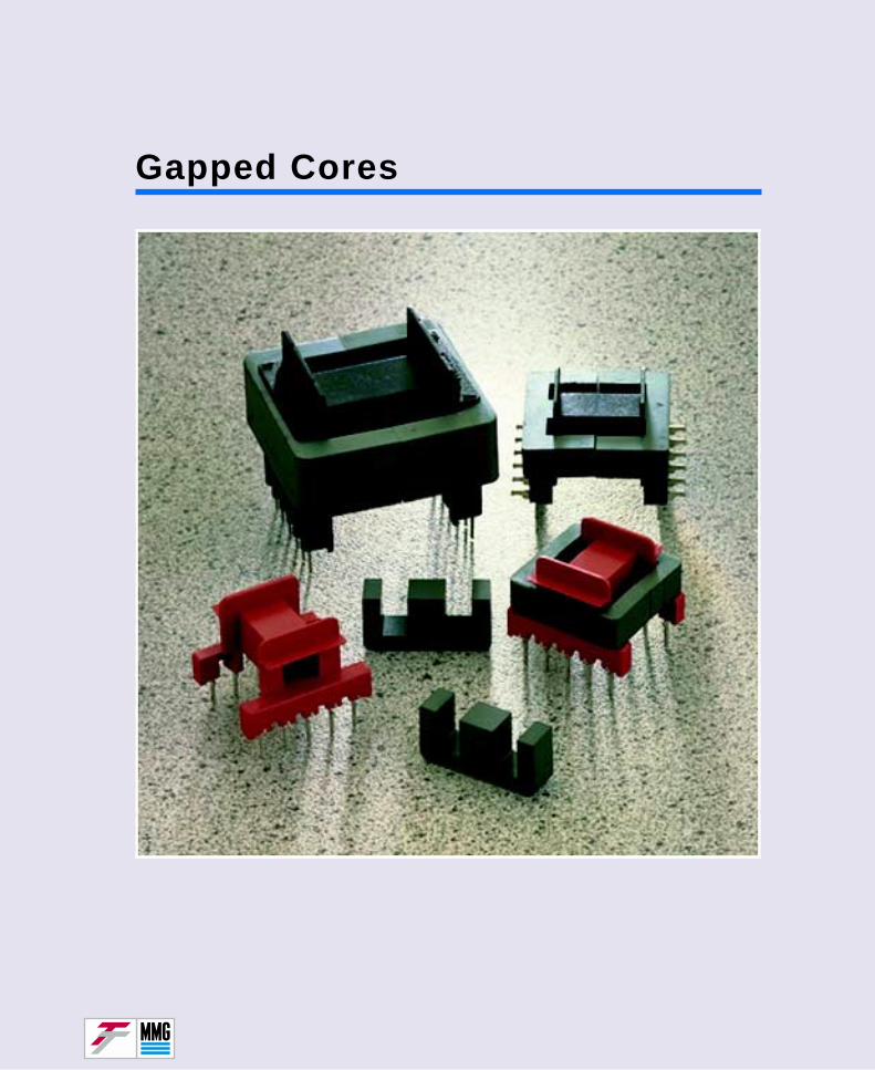
Gapped Cores
AL = or µe =0.4π.µe AL AΣ l
0.4π
Effect of an air gapA method is described below for the approximateevaluation of the effective permeability, µe of gappedE and U cores, at low flux densities. The AL valueswhich are of greater direct interest to the user, arerelated to µe by the formula:
...(1)
where AL (the inductance of one turn) is in nH.
(given in the component pages for specificcores) is in mm-1.
The demagnetising effect of magnetic poles on bothsides of an air gap makes the effective permeability ofa gapped core lower than the intrinsic permeability ofthe core material. The extent of this reduction in valuedepends on the magnetic reluctance of the flux pathin the core and on the reluctance of the air gap. It canbe written:
...(2)
where Rm is the reluctance of the flux path in the coreand Rgap is the reluctance of the air gap.
The value of Rm can be calculated from the publishedgeometric parameters of the core and the value ofthe intrinsic permeability of the core material.
...(3)
where le is the effective length and Ae is the effectivecross-sectional area of magnetic path.
To take the published le value for the above expres-sion is not strictly correct; the length of the gapshould be subtracted from le which is always given foran ungapped core, however the error is generallysmall. The value of Rgap is:
...(4)
While the total length of the air gap, lgap, presents noproblems, the cross-sectional area of the gap, is moredifficult to ascertain. The magnetic flux between polefaces on both sides of the gap is not strictly containedwithin the area of the poles. The magnetic lines barrel
AΣ l
AΣ l
µe = .µiRm
Rm + Rgap
Rm = .leAe
1µi
Rgap = (µ of air is 1)lgap
Agap
Agap = k.Apole
Rgap =lgap
k.Ae
µe =le . µi
le + .µi
lgap
k
out and, therefore, the cross-sectional area of the gapreaches its maximum halfway between the poles.
The effect can be taken into account by introducing acorrection factor, K (greater than 1):
...(5)
where Apole is the area of this part of the core wherethe gap is situated.
In the design of U and E cores, the general tendencyis to maintain the same cross-sectional area in all coreparts, so that the same flux density is maintained andthe losses are not increased in the narrower parts(losses increase with flux density raised to the powerof 2.2 to 2.6). Nevertheless, Apole is not necessarilyidentical with Ae. However to simplify the calculations,it can be approximated that Apole = Ae.
For an E42 core (32-110-25), Ae = 181mm2.Apole = 178.7mm2
For E56 x 37 x 19 (32-620-25), Ae =211mm2,Apole = 201mm2.
For U 65 x 37 x 19 (34-510-25), Ae =241mm2,Apole = 248mm2.
Formula (4) can now be written as follows:
...(6)
Introducing expressions (3) and (6) into (2):
...(7)
The value of k can be determined only experimentally( and not very accurately). In approximate calculation,the following values may be taken:
Gap length mm 0.1 0.2 0.5 1.0 2.0 3.0 4.0
k - 1.1 1.2 1.3 1.4 1.5 1.65 1.8
lgap mm 0.09 0.17 0.38 0.71 1.33 1.82 2.22k
If the total gap consists of two gaps, located indifferent parts of the magnetic circuit, a value of kshould be taken which corresponds to the half lengthof the total gap.
Formula (7) can be rearranged to show directly thevalue oflgap/k as a function of µe and µi :
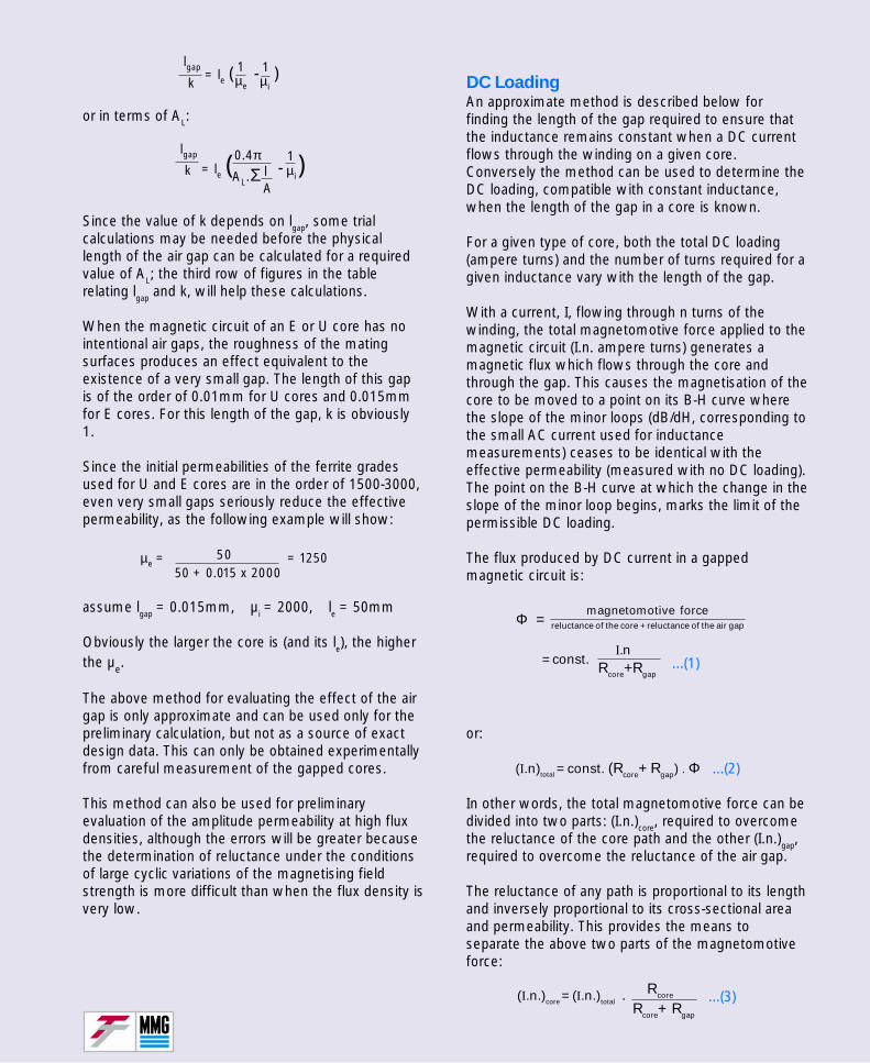
DC LoadingAn approximate method is described below forfinding the length of the gap required to ensure thatthe inductance remains constant when a DC currentflows through the winding on a given core.Conversely the method can be used to determine theDC loading, compatible with constant inductance,when the length of the gap in a core is known.
For a given type of core, both the total DC loading(ampere turns) and the number of turns required for agiven inductance vary with the length of the gap.
With a current, I, flowing through n turns of thewinding, the total magnetomotive force applied to themagnetic circuit (I.n. ampere turns) generates amagnetic flux which flows through the core andthrough the gap. This causes the magnetisation of thecore to be moved to a point on its B-H curve wherethe slope of the minor loops (dB/dH, corresponding tothe small AC current used for inductancemeasurements) ceases to be identical with theeffective permeability (measured with no DC loading).The point on the B-H curve at which the change in theslope of the minor loop begins, marks the limit of thepermissible DC loading.
The flux produced by DC current in a gappedmagnetic circuit is:
...(1)
or:
...(2)
In other words, the total magnetomotive force can bedivided into two parts: (I.n.)core, required to overcomethe reluctance of the core path and the other (I.n.)gap,required to overcome the reluctance of the air gap.
The reluctance of any path is proportional to its lengthand inversely proportional to its cross-sectional areaand permeability. This provides the means toseparate the above two parts of the magnetomotiveforce:
...(3)
or in terms of AL:
Since the value of k depends on lgap, some trialcalculations may be needed before the physicallength of the air gap can be calculated for a requiredvalue of AL; the third row of figures in the tablerelating lgap and k, will help these calculations.
When the magnetic circuit of an E or U core has nointentional air gaps, the roughness of the matingsurfaces produces an effect equivalent to theexistence of a very small gap. The length of this gapis of the order of 0.01mm for U cores and 0.015mmfor E cores. For this length of the gap, k is obviously1.
Since the initial permeabilities of the ferrite gradesused for U and E cores are in the order of 1500-3000,even very small gaps seriously reduce the effectivepermeability, as the following example will show:
assume lgap = 0.015mm, µi = 2000, le = 50mm
Obviously the larger the core is (and its le), the higherthe µe.
The above method for evaluating the effect of the airgap is only approximate and can be used only for thepreliminary calculation, but not as a source of exactdesign data. This can only be obtained experimentallyfrom careful measurement of the gapped cores.
This method can also be used for preliminaryevaluation of the amplitude permeability at high fluxdensities, although the errors will be greater becausethe determination of reluctance under the conditionsof large cyclic variations of the magnetising fieldstrength is more difficult than when the flux density isvery low.
lgap
k= le ( - )
1µe
1µi
lgap
k = le ( - )0.4π 1
µiAL.Σ lA
µe = = 12505050 + 0.015 x 2000
magnetomotive forcereluctance of the core + reluctance of the air gapΦ =
Rcore+Rgap
= const.I.n
(I.n)total = const. (Rcore+ Rgap) . Φ
(I.n.)core = (I.n.)total .Rcore+ Rgap
Rcore
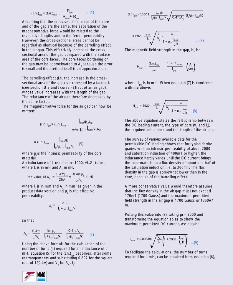
...(7)
The magnetic field strength in the gap, H, is:
where, lgap is in mm. When equation (7) is combinedwith the above,
...(8)
The above equation states the relationship betweenthe DC loading current, the type of core (Ve and le),the required inductance and the length of the air gap.
The survey of various available data for thepermissible DC loading shows that for typical ferritegrades with an intrinsic permeability of about 2000and saturation induction of 400mT or higher, theinductance hardly varies until the DC current bringsthe core material to a flux density of about one half ofthe saturation induction, i.e. to 200mT. The fluxdensity in the gap is somewhat lower than in thecore, because of the barrelling effect.
A more conservative value would therefore assumethat the flux density in the air gap must not exceed170mT (1700 Gauss) and the maximum permittedfield strength in the air gap is 1700 Gauss or 1350A/m.
Putting this value into (8), taking µi = 2000 andtransforming the equation so as to show themaximum permitted DC current, we obtain:
...(9)
To facilitate the calculations, the number of turns,required for L mH, can be obtained from equation (6),
...(4)
Assuming that the cross-sectional areas of the coreand of the gap are the same, the separation of themagnetomotive force would be related to therespective lengths and to the ferrite permeability.However, the cross-sectional areas cannot beregarded as identical because of the barrelling effectin the air gap. This effectively increases the cross-sectional area of the gap compared with the surfacearea of the core faces. The core faces bordering onthe gap may be approximated to Ae because the erroris small and the method itself is an approximation.
The barrelling effect (i.e. the increase in the cross-sectional area of the gap) is expressed by a factor, k(see section U,E and I cores - Effect of an air gap).whose value increases with the length of the gap.The reluctance of the air gap therefore decreases bythe same factor.The magnetomotive force for the air gap can now bewritten:
...(5)
where µi is the intrinsic permeability of the corematerial.An inductance of L requires n=1000, √L/AL turns,where L is in mH and AL in nH.
where le is in mm and Ae in mm2 as given in theproduct data section and µe is the effectivepermeability:
so that
...(6)
Using the above formula for the calculation of thenumber of turns (n) required for an inductance of LmH, equation (5) for the (I.n.)gap becomes, after somerearrangements and substituting 0.892 for the squareroot of 1/(0.4π) and Ve for Ae . le:-
the value of AL
(I.n.)gap = (I.n.)total . Rcore+ Rgap
Rgap
(I.n.)gap = (I.n.)total .le/Ae.µi + lgap/k.Ae
lgap/k.Ae
= (I.n.)total .le/µi + lgap/k
lgap/k
0.4π.µe
Σl/A =0.4π.µe
le/Ae
= (nH)
le + µi . lgap/k
le . µi µe =
0.4π AL = le/Ae
.le + µi. lgap/k
le . µi =le /µi+ lgap/k
0.4π.Ae
(I.n)gap = 1000.I. . .le/µi + lgap/k
lgap/k0.4π.Ae
L(le/µi + lgap/k)
klgap= 892.I.
Ve
L
1 + µi . le.klgap
µi.
Hgap = lgap lgap
(I.n.)gap=
10.(I.n.)gap Acm)(
klgap
Hgap = 8920.I. Ve
L
1 + µi . le.klgap
µi.
Imax = 0.00338kVe
L1 + 2000 . le.k
lgap )(
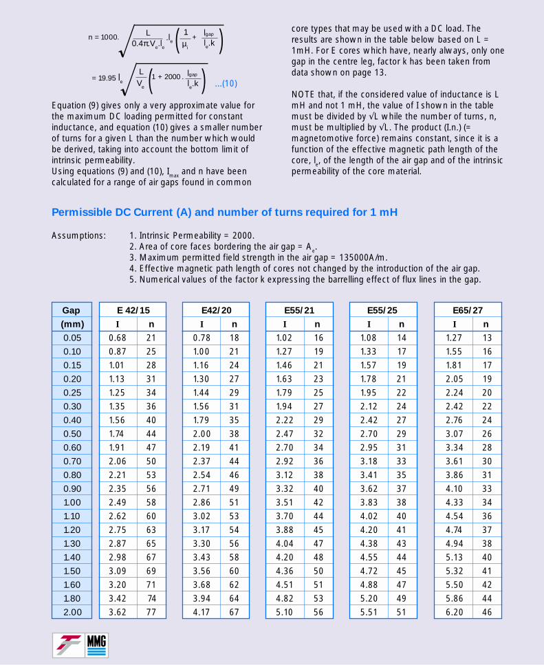
...(10)
Equation (9) gives only a very approximate value forthe maximum DC loading permitted for constantinductance, and equation (10) gives a smaller numberof turns for a given L than the number which wouldbe derived, taking into account the bottom limit ofintrinsic permeability.Using equations (9) and (10), Imax and n have beencalculated for a range of air gaps found in common
core types that may be used with a DC load. Theresults are shown in the table below based on L =1mH. For E cores which have, nearly always, only onegap in the centre leg, factor k has been taken fromdata shown on page 13.
NOTE that, if the considered value of inductance is LmH and not 1 mH, the value of I shown in the tablemust be divided by √L while the number of turns, n,must be multiplied by √L. The product (I.n.) (=magnetomotive force) remains constant, since it is afunction of the effective magnetic path length of thecore, le, of the length of the air gap and of the intrinsicpermeability of the core material.
Permissible DC Current (A) and number of turns required for 1 mH
Assumptions: 1. Intrinsic Permeability = 2000.2. Area of core faces bordering the air gap = Ae.3. Maximum permitted field strength in the air gap = 135000A/m.4. Effective magnetic path length of cores not changed by the introduction of the air gap.5. Numerical values of the factor k expressing the barrelling effect of flux lines in the gap.
Gap E 42/15 E42/20 E55/21 E55/25 E65/27
(mm) I n I n I n I n I n
0.05 0.68 21 0.78 18 1.02 16 1.08 14 1.27 130.10 0.87 25 1.00 21 1.27 19 1.33 17 1.55 160.15 1.01 28 1.16 24 1.46 21 1.57 19 1.81 170.20 1.13 31 1.30 27 1.63 23 1.78 21 2.05 190.25 1.25 34 1.44 29 1.79 25 1.95 22 2.24 200.30 1.35 36 1.56 31 1.94 27 2.12 24 2.42 220.40 1.56 40 1.79 35 2.22 29 2.42 27 2.76 240.50 1.74 44 2.00 38 2.47 32 2.70 29 3.07 260.60 1.91 47 2.19 41 2.70 34 2.95 31 3.34 280.70 2.06 50 2.37 44 2.92 36 3.18 33 3.61 300.80 2.21 53 2.54 46 3.12 38 3.41 35 3.86 310.90 2.35 56 2.71 49 3.32 40 3.62 37 4.10 331.00 2.49 58 2.86 51 3.51 42 3.83 38 4.33 341.10 2.62 60 3.02 53 3.70 44 4.02 40 4.54 361.20 2.75 63 3.17 54 3.88 45 4.20 41 4.74 371.30 2.87 65 3.30 56 4.04 47 4.38 43 4.94 381.40 2.98 67 3.43 58 4.20 48 4.55 44 5.13 401.50 3.09 69 3.56 60 4.36 50 4.72 45 5.32 411.60 3.20 71 3.68 62 4.51 51 4.88 47 5.50 421.80 3.42 74 3.94 64 4.82 53 5.20 49 5.86 442.00 3.62 77 4.17 67 5.10 56 5.51 51 6.20 46
n = 1000.1
µi
+le.klgap( ).le
L 0.4π.Ve.le
1 + 2000 . le.klgap )= 19.95 le Ve
L (
Product Quality

Committed to Quality
MMG-Neosid is committed to quality and recog-nizes the need to manufacture products to meet thehighest quality standards of the marketplace,together with first class customer service in all itsaspects. Our quality assurance team constantlymonitor performance of product and service tomaintain the high standards and to promote contin-ued improvement.The quality system operated complies with thestandard BS EN ISO 9000.
Product QualityA comprehensive analysis of the manufacturingprocess, giving full traceability of materials and testdata is an ongoing operation. Strategically placedchecks where materials and products are subject toapproval testing, monitors the complex process. Aflow chart overleaf shows these QA control meas-ures.
Final InspectionAt the end of the manufacturing process each batchof components is subjected to final inspection. Asampling system in accordance with BS6001(identical to ISO 2859-1) is used to select samplesfor test. Acceptable quality levels (AQL’s) are set fordifferent classes of defects. Emphasis is placed oncontinuous process monitoring and improvement,to build in quality.
Fitness for Use and ReliabilityOnce assembled into finished tested product, it isparticularly rare for ferrite components to fail duringnormal use. In general, soft ferrite cores form asingle component in a wound product. Manysources of failure for the product may not be thefault of the ferrite core. MMG-Neosid considerscustomer feedback an integral part of the QAprocess, ensuring possible future problems areaverted at an early stage.
Classification of DefectsEvery manufactured component has a mechanicaland electrical specification developed not justthrough standard performance data but alsothrough many years of manufacturing experienceand a broad knowledge base of the applications forwhich they are intended. If a component does notcomply with these specifications it is considereddefective. Defects are classified into two distinctcategories; major and minor.
Major defects are those affecting the fit of thecomponents into their respective accessories(mechanical) or the ability of the finished assembledproduct to function (electrical). Minor defects arethose that do not affect the performance of thefinished product.
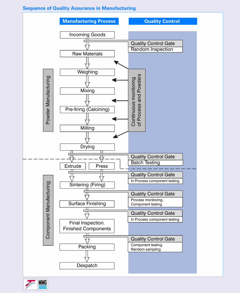
Sequence of Quality Assurance in Manufacturing
Manufacturing Process Quality Control
Quality Control Gate
Quality Control Gate
Incoming Goods
Raw Materials
Weighing
Mixing
Pow
der
Man
ufac
turin
gC
ompo
nent
Man
ufac
turin
g
Pre-firing (Calcining)
Milling
Drying
Extrude Press
Sintering (Firing)
Surface Finishing
Packing
Despatch
Final Inspection.Finished Components
In Process component testing
In Process component testing
Process monitoring.Component testing
Component testing.Random sampling
Quality Control Gate
Quality Control Gate
Quality Control Gate
Quality Control Gate
Batch Testing
Random Inspection
Con
tinuo
us m
onito
ring
of P
roce
ss a
nd P
owd
ers
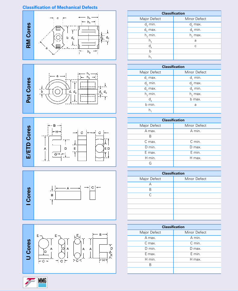
Classification
Major Defect Minor Defectd2 min. d2 max.d3 max. d3 min.h2 min. h2 max.
h3 ad4 cbh1
Classification
Major Defect Minor Defectd1 max. d1 min.d2 min. d2 max.d3 max. d3 min.h2 min. h2 max.
d4 b max.b min. a
h1
Classification
Major Defect Minor DefectA max. A min.
BC max. C min.D min. D max.E max. E min.H min. H max.
G
Classification
Major Defect Minor DefectABC
Classification
Major Defect Minor DefectA max. A min.C max. C min.D min. D max.E max. E min.H min. H max.
B
RM
Co
res
Po
t C
ore
sE
/ET
D C
ore
sI
Co
res
U C
ore
s
Classification of Mechanical Defects
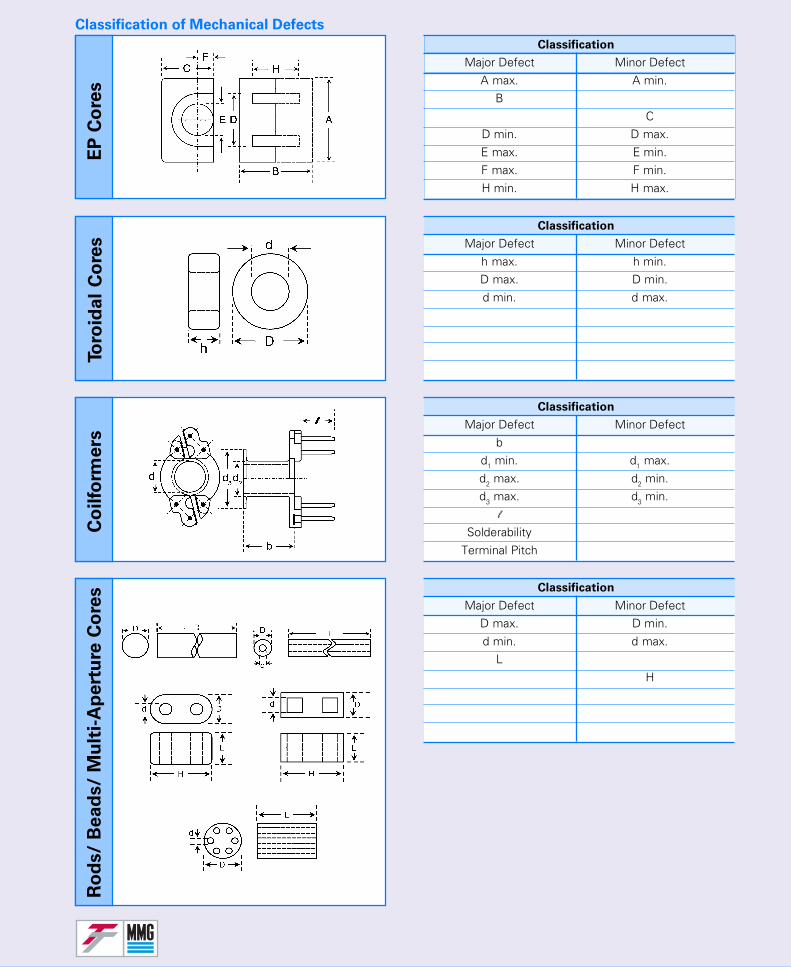
Classification
Major Defect Minor DefectA max. A min.
BC
D min. D max.E max. E min.F max. F min.H min. H max.
Classification
Major Defect Minor Defecth max. h min.D max. D min.d min. d max.
Classification
Major Defect Minor Defectb
d1 min. d1 max.d2 max. d2 min.d3 max. d3 min.
l
SolderabilityTerminal Pitch
Classification
Major Defect Minor DefectD max. D min.d min. d max.
LH
EP
Co
res
Toro
idal
Co
res
Co
ilfo
rmers
Ro
ds/
Bead
s/
Mu
lti-
Ap
ert
ure
Co
res
Classification of Mechanical Defects
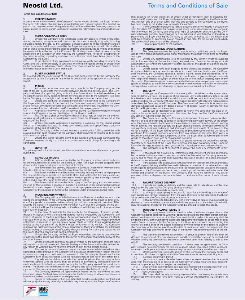
Neosid Ltd. Terms and Conditions of SaleTerms and Conditions of Sale
1. INTERPRETATIONIn these terms and conditions “the Company” means Neosid Limited “the Buyer” meansthe party with whom the Company is contracting and “goods”, where the context sopermits and requires, means the goods and/or services which the Company contracts tosupply and/or to provide and “Conditions” means the following terms and conditions ofsale.
2. THESE CONDITIONS APPLY2.1 Unless the Company shall otherwise expressly agree in writing every offer,tender, quotation, acceptance and contract for the sale or supply of goods, includingservices ancillary thereto, by the Company is made subject to these conditions and allother terms and conditions proposed by the Buyer are expressly excluded. No modifica-tion of these terms and conditions shall be effective unless reduced to writing and signedby a person duly authorised by the Company. No binding contract shall be created by theacceptance of a quotation or offer made by the Company until notice of acceptance ofthe order in writing signed by a person duly authorised shall have been given to theCompany by the Buyer.2.2 In the absence of any agreement in writing expressly excluding or varying theConditions the Conditions apply to contracts for the sale of goods arising on acceptanceby the Company, by whatever means, of any order received via the interchange of data byteletransmission (Electronic Data Exchange).
3. BUYER’S CREDIT STATUSUnless and until the credit status of the Buyer has been approved by the Company theacceptance by the Company of any order is conditional on its approval of such creditstatus.
4. PRICES4.1 All tender prices are based on costs payable by the Company ruling on thedate of tender. Such costs may increase between tender and delivery date. The Com-pany shall have the right, by giving notice to the Buyer at any time before delivery, toincrease the price of any goods to reflect any increase in cost to the Company. Exerciseby the Company of this right shall not entitle the Buyer to cancel the contract.4.2 Where any additional or changed information is submitted to the Company bythe Buyer after the date of the Contract the Company reserves the right to increaseprices to cover any additional costs (including additional overheads) incurred by the Com-pany as a result of such alteration and/or to extend the delivery period.4.3 All prices are ex works unless otherwise stated. Carriage by whatever methodmay, at the Company’s option, be charged to the Buyer in addition.4.4 The Company shall be entitled to charge at such rate as shall be fair and rea-sonable for all preliminary or development work which the Company carries out at therequest of the Buyer.4.5 Unless previously withdrawn a quotation is available for the period statedtherein or, if no period is stated, for thirty days from its date, and lapses if not previouslyaccepted, at the end of that time.4.6 The Company shall be entitled to make a surcharge for fulfilling any order witha value less than such minimum as the Company shall from time to time fix as its currentminimum order price.4.7 Where the Buyer requests items to be supplied with release certificates theCompany reserves the right to make an extra and reasonable charge for providing suchcertificates.
5. QUANTITYThe price quoted is for the stated quantities only and not for materially lesser or greaterquantities.
6. SCHEDULE ORDERS6.1 A Schedule Order, when accepted by the Company, shall constitute authorityfor the manufacture of all goods in the Schedule Order. The Buyer shall be obliged to takedelivery of and pay for all goods in the Schedule Order.6.2 The Buyer shall take delivery of goods in a Schedule Order within twelve monthsfrom the date of acceptance of the Schedule Order by the Company.6.3 The Buyer shall be entitled by notice in writing to bring forward or to postponethe date of delivery of goods in a Schedule Order but, unless the Company expresslyotherwise agrees in writing, not in the case of custom goods by less than eight weeks’notice and in any other case by less than four weeks’ notice.6.4 The Buyer shall at all times be liable to pay to the Company all costs and lossesincurred by the Company in respect of goods in a Schedule Order including (but withoutlimitation) those in respect of finished goods, work in progress, materials acquired by theCompany for the purpose of fulfilling the Schedule Order and manufacturing tools.
7. INVOICING AND PAYMENT7.1 The Company will be entitled to invoice the Buyer on the date on which thegoods are despatched. If the Company agrees at the request of the Buyer to defer deliv-ery of any goods or suspends delivery of any goods in accordance with condition 7.8 orextends the delivery in accordance with condition 4.2 or 8.2, the Company will be enti-tled to invoice the Buyer for such goods on the date on which they would otherwise havebeen due for despatch.7.2 In the case of contracts for the supply by the Company of custom goods,charges for design artwork and tooling charges may be invoiced by the Company at thetime of shipment of the first prototype. Minor component or layout changes not affect-ing costs may at the Company’s discretion be accepted without extra charge, providednotification is received in writing before design starts or within three working days ofreceipt by the Company of the Buyer’s order, whichever is the earlier. The Companyreserves the right to invoice at the time of shipment of the first prototype any additionaldesign tooling or prototype manufacturing charges arising from changes requested bythe Buyer after the contract has been entered into.7.3 Unless the Company notifies the Buyer otherwise, payment is due, whetheror not title to the goods has passed to the Buyer, by the end of the month following themonth of invoice.7.4 Unless otherwise expressly agreed in writing by the Company, payment in fullwithout discount shall be made in Pounds Sterling and the Buyer shall not be entitled forany reason to withhold payment of the amount shown on the invoice as due.7.5 Payment is made and received only at the time when cash is handed to a dulyauthorised representative of the Company who issues an official written receipt thereforor when any cheque or draft sent or delivered to the Company is cleared and/or theCompany’s bank account credited with the relevant amount, and not at any earlier time.7.6 If goods are for delivery outside the United Kingdom, the Company, unlessotherwise agreed with the Buyer, shall be entitled to payment by irrevocable letter ofcredit confirmed by a bank approved in writing by the Company against the usual docu-ments. The Buyer shall reimburse to the Company any costs and expenses which areincurred by the Company in receiving payment by irrevocable letter of credit.7.7 The Company reserves the right to charge interest at the rate of three per centper annum above Midland Bank plc base rate for the time being on all overdue accountsfrom the due date until the date of actual payment.7.8 Failure to make payment on due date shall constitute a breach of contract andwithout prejudice to any other rights which it may have against the Buyer the Company
may suspend all further deliveries of goods under all contracts then in existence be-tween the Company and the Buyer until payment of all sums payable by the Buyer underthat contract and of all other sums then due and payable to the Company by the Buyerhas been made in full and/or may terminate the contract.7.9 If the Company exercises its right to suspend delivery of goods in accordancewith Condition 7.8 the dates for delivery of all goods under all contracts in existence atthe time when the Company exercises such right of suspension shall, unless the Com-pany otherwise decides, be postponed by a period equal in length to that of the delay inpayment by the Buyer entitling the Company to suspend deliveries (or, if the suspensionshall be in respect of payments due on more than one date, for the period during whichthe earliest such payment shall be delayed).7.10 Time for payment is of the essence.
8. MANUFACTURING SPECIFICATIONS8.1 The Company reserves the right to supply, without additional cost to the Buyer,goods with a technical specification higher than that of the goods which it has contractedto supply.8.2 Where any specification is to be supplied by the Buyer it must be suppliedwithin fourteen days of the contract being entered into. Delay in the supply of suchspecification will entitle the Company to defer delivery of the goods by a period equiva-lent to the delay.8.3 Where goods have been supplied to the Buyer’s specification, the Companyaccepts no liability for any defect in goods which meet that specification and the Buyershall indemnify the Company against all actions, claims, costs and proceedings, in re-spect of such goods including claims that the specification or goods infringe(s) any pat-ent, registered design, copyright or other industrial or intellectual property right of anythird party. The Company gives no warranty as to the fitness for any particular purpose ofgoods so supplied to the Buyer’s own specification and accepts no liability for clerical orstenographical errors on any drawings or specification provided by the Buyer.
9. DELIVERY9.1 Although the Company will make every effort to deliver on the agreed date,time for delivery is not of the essence of the contract. Any quoted delivery date or periodis a business estimate only and is conditional on the Buyer, at the time of placing theorder, providing the Company with such information concerning the Buyer’s requirementsas enables the Company to fulfil the order. The Company shall be not liable for any loss ordamage whatsoever caused by delayed delivery of goods. Delay in delivery will notentitle the Buyer to rescind the contract.9.2 Goods will be deemed to be delivered within five days after the date of in-voice, unless prior to the expiry of such five days, the Buyer notifies the Company andany carrier in writing of non-delivery.9.3 The Buyer must notify the Company by telephone of any non delivery or shortdelivery or loss of or damage to goods in transit immediately upon delivery of the goodsor of the invoice therefor (whichever is the earlier) and must confirm the same in writingwithin seventy two hours thereafter; the Buyer shall at the same time notify any carrier inwriting of any such loss or damage and, if relevant, shall enter a note of the same on thecarrier’s receipt. If the Buyer fails to give notice as provided above and the Company isprecluded from making recovery whether from any insurer or any other third party inrespect of the loss or damage complained of, then the Buyer shall be liable to pay for thegoods as though no such loss or damage had occurred.9.4 If any carrier of any consignment of goods receives an unqualified receipttherefor by or on behalf of the Buyer, the Company shall have no liability to the Buyer forloss of or damage in transit to such goods or for misdelivery or non delivery thereof.9.5 The Company may at its discretion deliver the goods by instalments in anysequence.9.6 If the goods are delivered by instalments each instalment shall be deemed tobe the subject of a separate contract and no default or failure by the Company in respectof any one or more instalments shall avoid the contract in respect of goods previouslydelivered or undelivered goods.9.7 If the goods are to be delivered to the Buyer at any location other than premisesof the Company, delivery shall be deemed to take place on arrival of the vehicle transport-ing the goods at that location and the Buyer shall be responsible for unloading the goods.Personnel of the Company involved in such unloading shall be deemed to be under thecontrol and direction of the Buyer. The Company shall have no liability for any act oromission of any such personnel done or failed to be done in the course of such unload-ing.
10. FAILURE TO TAKE DELIVERY10.1 If goods are ready for delivery and the Buyer fails to take delivery at the timerequired by the contract the Company shall be entitled:-10.1.1 to invoice such goods forthwith; and10.1.2 to charge at rates giving an economic return for the handling and storage ofsuch goods, and for their insurance, from the date of invoice to the date when the Buyertakes delivery or the Company disposes of the same.10.2 If the Buyer fails to take delivery within thirty days of date of invoice it shall bedeemed to have repudiated the contract and without prejudice to any other right which itmay have against the Buyer, the Company shall be entitled to resell the goods.
11. WARRANTY AGAINST DEFECTS11.1 The Company warrants that at the time when they leave the premises of theCompany all goods correspond with their specification and are free from defect in mate-rial and workmanship provided that the Company’s liability under this warranty shall belimited to either, at the Company’s discretion, replacement or repair of goods free of costto the Buyer or payment by the Company to the Buyer of an amount not exceeding theoriginal purchase price of the goods in respect of which notice of the defect is given tothe Company within twelve months of the date of invoice and which are returned to theCompany carriage paid within seven days of the Buyer first becoming aware of the de-fect.11.2 The warranty contained in condition 11.1 above is given in lieu of and shall bedeemed to exclude all other warranties and conditions whether express or implied andwhether arising by common law statute or otherwise other than relating to title to thegoods.11.3 The warranty contained in condition 11.1 above does not apply to and the Com-pany accepts no responsibility for defects in goods which have been tested in accord-ance with the Buyer’s express contractual requirements and have satisfied such tests.11.4 Unless otherwise expressly agreed by the Company the warranty containedin condition 11.1 does not apply to and the Company accepts no responsibility for:-11.4.1 damage occurring in transit11.4.2 goods which have suffered or been subject to use otherwise than in accord-ance with the instructions or advice of the Company or undue wear and tear, accident,mis-use, improper application, neglect or overloading;11.4.3 goods which have not been operated and maintained in accordance with writ-ten operation and maintenance instructions supplied by the Company; or11.4.4 consumable items.11.5 The Buyer shall not rely upon any representation concerning any goods sup-plied unless the same shall have been made by a person authorised by the Company inwriting.
12. TESTSIf the Buyer requires special tests, witness tests or site tests the Company shall be enti-tled to make a reasonable charge for conducting them, unless the Company shall other-wise have agreed in writing.
13. RETENTION OF TITLE13.1 The legal and equitable title to the goods supplied under the contract (in thiscondition referred to as “the contract goods” which expression includes any of them)will not pass to the Buyer until the price for the contract goods has been paid in full anduntil such payment the Buyer will hold them in a fiduciary capacity as bailee for the Com-pany.13.2 Notwithstanding the provisions of condition 13.1 above, the Buyer shall beentitled to dispose of the goods for the account of the Company (but so that any warran-ties, conditions or representations given or made by the Buyer to his customer shall notbind the Company which shall be indemnified by the Buyer in respect thereof) and topass good title to the goods to any customer which is a bona fide purchaser for valuewithout notice of the Company’s rights.13.3 Where the contract goods are resold by the Buyer and at the time of suchresale the property in such goods has not passed to the Buyer then the proceeds of suchresale will be held by the Buyer in a fiduciary capacity on trust for the Company and theBuyer will account to the Company for the same to the extent necessary to pay the pricefor the contract goods and the Company shall have the additional right to recover in thename of the Buyer (for which purpose the Company is hereby appointed the Buyer’sattorney) any price payable to the Buyer by his customer but if it shall exercise such rightthe Company shall account to the Buyer for the balance of the amounts recovered afterrecouping all debts due to the Company from the Buyer and the costs of such recovery.13.4 The Buyer shall so long as the Company is entitled to the property in the con-tract goods store the contract goods so that they are identifiable as the property of theCompany.13.5 Without prejudice to any of the Company’s other rights (whether to damagesor under contract or otherwise howsoever) the Company may at any time after the pricefor the contract goods has become due and remains unpaid rescind the contract and/orrecover any contract goods which are still the property of the Company. By entering intothis contract the Buyer hereby authorises the Company’s servants and agents to enterinto any premises of the Buyer for that purpose.
14. RISK14.1 Risk in the goods shall pass to the Buyer on delivery thereof.14.2 The Buyer shall keep the goods fully insured against all risks normally insuredagainst throughout the period between the risk therein passing to the Buyer and theproperty therein ceasing to remain with the Company.14.3 All items and materials which are the property of the Buyer or which are sup-plied by the Buyer to the Company shall while in the possession of the Company or intransit to or from the Buyer be at the Buyer’s risk, unless otherwise expressly agreed inwriting by the Company.
15. COMPANY’S REMEDIES15.1 If the Buyer shall make default in any material respect in its obligations to theCompany, or if any distress or execution shall be levied upon the Buyer’s property orassets, or if the Buyer shall make or offer any arrangement or composition with its credi-tors or if there shall be any other grounds upon which the Buyer shall become insolventfor the purposes of the Insolvency Act 1986 or any resolution or petition to wind up theBuyer or for the appointment of an administrator of the Buyer shall be passed or pre-sented the Company (without prejudice to any other right to which it may be entitled):-15.1.1 may suspend or terminate the contract or any unfulfilled part thereof withoutprejudice to its existing rights thereunder;15.1.2 may stop any goods in transit;15.1.3 may recover from the Buyer’s premises any goods which are the property ofthe Company; and15.1.4 shall be entitled to claim against the Buyer for any loss or damage sustainedas a result of such suspension or termination.15.2 If items or materials supplied by the Buyer for working by the Company aredefective the Buyer shall be liable to the Company for the cost of all work performed bythe Company thereon including work to remedy such defects.
16. LIMITATION OF LIABILITY16.1 Except as otherwise expressly provided in these conditions, or in respect ofpersonal injury or death caused by the negligence of the Company, the Company shall beunder no liability in respect of the quality, condition or description of the goods or for lossor damage including consequential loss or damage howsoever caused to the Buyer or toany other person, and whether for breach of any express or implied provision of thecontract or for negligence, breach of statutory or other duty on the part of the Companyor otherwise arising out of or in connection with the performance or non-performance orpurported performance of the contract.16.2 If items or materials are supplied by the Buyer to the Customer for work to beperformed on them or for incorporating with goods to be supplied by the Company to theBuyer the liability of the Company for defective work shall be limited to rectifying thework or satisfactorily repairing the work or to carrying out like work on replacement itemsor materials supplied by the Buyer free of charge and in no event shall any such liability ofthe Company continue after the items concerned have been inspected or delivered orleft the United Kingdom whichever shall be the earliest.
17. INDEMNITY BY BUYERThe Buyer shall indemnify the Company against all liabilities costs and expenses whichthe Company may incur by reason of any claim by any subsequent purchaser or user ofthe goods or of any product incorporating the goods or manufactured by using the goodsor by reason of any claim by any relative or dependant of such purchaser or user arisingfrom any defect or alleged defect in the goods or in such product except and to the extentthat such liabilities, costs and expenses arise from a breach by the Company of its obliga-tions under these conditions.
18. RETURNED GOODS18.1 No contract for goods ordered may be cancelled by the Buyer and save asotherwise provided in these conditions no goods may be returned without the prior writ-ten consent of the Company.18.2 If the Company agrees to accept return of any goods the Buyer shall be obligedto effect the return of such goods in good condition and at its own risk and cost.18.3 Notwithstanding any agreement to accept return of goods the Company willnot be obliged to accept delivery of any returned goods unless they are returned in car-tons which are undamaged and which have not been opened since their despatch by theCompany.
19. HEALTH AND SAFETY19.1 The Company has available up-to-date information and/or product literatureconcerning the conditions necessary to ensure that the goods supplied will be safe andwithout risk to health when properly used. This information is and will remain availablefrom the Company.19.2 The Buyer shall be solely responsible for and shall keep the Company indem-
nified against any loss, liability or expenses arising directly or indirectly from use of thegoods other than in accordance with their specification or the Company’s operatinginstructions or the information and product literature referred to in condition 19.1 or (whereno such specifications or instructions exist) in a manner which could not reasonably beconsidered to be safe and without risk.19.3 If the Company has an obligation under the contract to carry out installationworks the Buyer is responsible for ensuring that any site at which installation is to becarried out the condition of the site and activities of the Buyer and of third parties at thesite comply with statutory requirements relating to conditions of work performance ofsuch activities and otherwise and that the servants agents sub-contractors and officersof the Company are not exposed to risks to their health and safety during or as a result ofworking at the site.
20. INSTALLATIONWhere the obligations of the Company include installation, the Buyer will provide suit-able access to the installation site and conditions for safe and unobstructed installationand all lighting heating and power supplies and facilities (including without limitationlifting tackle cranes and scaffolding) which the Company requires for or in connectionwith the installation. If at the time when delivery of the goods is effected installationcannot be undertaken by reason of any failure by the Buyer to comply with its obligationsunder the foregoing provisions of this paragraph, all expenses and extra costs incurred bythe Company as a result of or in connection with the inability to undertake installationand/or any resulting delay in installation, including a reasonable charge for the time ofemployees, will be charged by the Company to the Buyer.
21. EXPORT ONLY21.1 If the Company concludes the contract of carriage and/or arranges for the in-surance of the goods for transit the Company shall be deemed to be acting solely as theBuyer’s agent and sub-sections (2) and (3) of Section 32 of the Sale of Goods Act 1979shall not be applicable.21.2 In the case of any goods to be exported from the United Kingdom, the Buyeris responsible for obtaining import authorisations, and the Company shall have no obliga-tion to despatch the goods unless and until the Buyer has provided all documentationand information necessary for export and import of the goods to be effected.
22. SPECIFICATIONS ETCExcept as otherwise expressly agreed in writing, all specifications, patterns, drawings,unregistered designs, dies, moulds, tools and the like produced by the Company shallremain the property of the Company. The Buyer may not utilise, reproduce or communi-cate knowledge of such items and the Buyer shall return the same to the Company at theCompany’s request.
23. CUSTOMER RETURNABLE PACKAGESIf the contract is for the supply of goods to be delivered in the United Kingdom and theCustomer and the Buyer have not otherwise agreed, customer returnable packages usedfor delivery of the goods shall remain the property of the Company and must be returnedby the Buyer to the Company within one month of such delivery in the same condition asreceived by the Buyer. Customer returnable packages not so returned will be charged atreplacement cost and the Buyer shall be liable to the Company accordingly.
24. TECHNICAL DATAWhilst every effort has been made to ensure the accuracy of any technical data providedto the Buyer, the Company accepts no liability arising from errors or omissions therein.Illustrations, photographs, weights, dimensions and descriptions are illustrative and forgeneral guidance and do not form the basis of any sale by description. Performancefigures quoted by the Company for its products are similarly illustrative and for generalguidance, are based upon experience and are not warranted.
25. PRINCIPALSThe contract is between the Company and the Buyer and shall not be assignable withoutthe express written consent of the Company. The Company reserves the right to sub-contract the fulfilment of any order or contract or any part thereof.
26. FORCE MAJEUREThe Company shall not be liable for failure to comply with any of its obligations under thecontract in the event that compliance is delayed or prevented by any cause whatsoeverbeyond its reasonable control, including, but not limited to, war, riot. strike, lock-out, actof God, storm, fire, earthquake, explosion, flood, confiscation, action of any governmentor government agency or shortage.
27. RIGHTS OF COMPANYNo forbearance or indulgence by the Company shown or granted to the Buyer in respectof the terms and conditions of sale of the goods shall affect or prejudice the rights of theCompany against the Buyer.
28. SET OFFThe Buyer shall not be entitled to the benefit of any set-off to which the Buyer might beotherwise entitled in law or in equity. All sums payable under the contract will be payablewithout any deduction and the Company shall be entitled in the event of non-payment toobtain and enforce judgement thereon without any stay of execution pending the deter-mination of any cross or counter claim by the Buyer.
29. CONFIDENTIALThe existence of the contract its content and subject matter are confidential and shall notbe disclosed by the Buyer without the prior written consent of the Company.
30. EFFECT OF INVALID PROVISIONSIf any provision of the contract is held to be invalid, illegal or unenforceable in any way,the validity, legality and enforceability of the remaining provisions shall not be affected orimpaired in any way.
31. NOTICEAny notice under the contract shall be in writing sent by first class pre-paid letter post orfacsimile transmission confirmed by first class pre-paid letter post. Any notice to theCompany shall be addressed to the Company at its registered office and to the Buyer atthe address notified by the Buyer to the Company for that purpose or if none is so noti-fied to the address of the Buyer last known to the Company. A notice given as aforesaidby post shall be deemed served forty eight hours after posting and by facsimile at thetime of transmission thereof.
32. HEADINGSHeadings are inserted for convenience only and shall not affect the meaning or construc-tion of these conditions.
33. PROPER LAWThese conditions and the contract shall be subject to and construed in accordance withEnglish Law and the parties hereby agree to accept the exclusive jurisdiction of the Eng-lish Courts in all matters connected therewith or relating thereto.
December 1997Issue 1
Neosid Ltd. Terms and Conditions of Sale
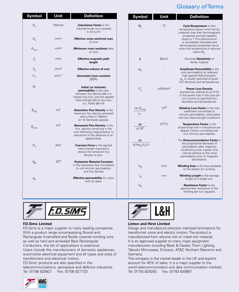
F.D.Sims Limited
F.D.Sims is a major supplier to many leading companies.With a product range encompassing Round andRectangular Enamelled and Textile covered winding wireas well as hard and annealed Bare RectangularConductors, the list of applications is extensive.Users include the manufacturers of domestic appliances,automotive electrical equipment and all types and sizes oftransformers and electrical motors.F.D.Sims’ products are also specified in thetelecommunications, aerospace and defence industries.Tel: 01706 825821 Fax: 01706 827723
Linton and Hirst Limited
Design and manufacture precision stamped laminations fortransformer cores and electric motors. The product ismanufactured from silicone iron or nickel iron material.It is an approved supplier to many major equipmentmanufacturers including Black & Decker, Thorn Lighting,Tabushi Microwave, Ericsson, AT&T, Northern Telecoms andSiemens.The company is the market leader in the UK and exportsaccount for 45% of sales. It is a major supplier to theworld telecommunication and data communication markets.Tel: 01793 825000 Fax: 01793 820667
Glossary of Terms
Symbol Unit Definition
AL Henrys Inductance Factor is theinductance per turn squared
in nH (L/n²)
Ae mm² Effective cross sectional area
of core
Amin mm² Minimum cross sectional areaof core
le mm Effective magnetic path
length
Ve mm³ Effective volume of core
C1 mm¯¹ Geometric Core constant
(Σl/A)
µi - Initial (or intrinsic)
permeability is the ratiobetween flux density ∆B in a
closed ring core, and the appliedfield strength ∆H at very low
a.c. fields (∆H>0)
Bsat mT Saturation Flux Density is themaximum flux density achieved
with a field of 796A/m(or 10 Oersteds) applied.
BremmT Remanent Flux Density is the
flux density remaining in thecore (following magnetisation tosaturation) in the absence of an
applied field.
Hc A/m Coersive Force is the appliedfield strength required toreduce the remanent flux
density to zero.
ηB 10¯6 Hysteresis Material Constant
is the hysteresis loss normalisedto unit intrinsic permeability
and flux density.
µe - Effective permeability for coreswith air gaps.
Symbol Unit Definition
Θc °C Curie Temperature is thattemperature above which ferrite
materials lose their ferromagnetic properties and permeabilitydrops to 1. This phenomenonis completely reversible and
ferromagnetic properties returnwhen the temperature is reduced
below Θc.
ρ Ω-cm Electrical Resistivity offerrite material
µa - Amplitude Permeability is thecore permeability at relativelyhigh applied field strengths.
µa is usually specified at givenflux densities and temperatures.
Pv mW/cm³ Power Loss Density
(sometimes referred to as PLD) is the power loss in the core per
unit volume at specified fluxdensities and temperatures.
tan δ(r+e) 10¯6 Relative Loss Factor is the losscoefficient normalised to
intrinsic permeability, associatedwith low field strength conditions.
∆µ 10¯6/°C Temperature Factor is theproportional rise in inductance per
degree Celsius normalised perunit intrinsic permeability.
∆µ - The Disaccommodation Factor isthe proportional decrease ofpermeability after magnetic
conditioning over a given timeinterval relative to the initial
permeability prior to magneticdisturbance.
AN mm² Winding Area is the area availableon the bobbin for winding.
IN mm Winding Length is the averagelength of a single turn.
AR - Resistance Factor is theapproximate resistance of the
winding per turn squared.
µi
µi².∆T
µi²log10(t2/t1)