pulsar 320 quick start guide - advanced illumination · pulsar 320 quick start guide pulsar 320...
TRANSCRIPT
Pulsar 320 Quick Start Guide
Pulsar 320 Quick Start Guide
Pulsar 320 Quick Start Guide Pulsar 320 Quick Start Guide
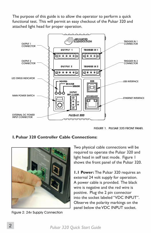
The purpose of this guide is to allow the operator to perform a quick functional test. This will permit an easy checkout of the Pulsar 320 and attached light head for proper operation.
I. Pulsar 320 Controller Cable Connections:
Two physical cable connections will be required to operate the Pulsar 320 and light head in self test mode. Figure 1 shows the front panel of the Pulsar 320.
1.1 Power: The Pulsar 320 requires an external 24 volt supply for operation. A power cable is provided. The black wire is negative and the red wire is positive. Plug the 2 pin connector into the socket labeled “VDC INPUT”. Observe the polarity markings on the panel below the VDC INPUT socket.
Figure 2: 24v Supply Connection
2
Pulsar 320 Quick Start Guide Pulsar 320 Quick Start Guide
Power Requirements: The input power connector is located near the bottom center of the Pulsar 320’s front panel. The Pulsar 320 requires an external 24 volt supply for operation. The power supply needs to have sufficient amperage rating to drive the light head in the desired mode of operation. Advanced illumination recommends a minimum of 4A for full output operation.
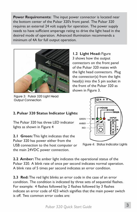
1.2 Light Head: Figure 3 shows how the output connectors on the front panel of the Pulsar 320 mates with the light head connectors. Plug the connector(s) from the light head(s) into the 5 pin socket in the front of the Pulsar 320 as shown in Figure 3.
2. Pulsar 320 Status Indicator Lights:
The Pulsar 320 has three LED indicator lights as shown in Figure 4
2.1 Green: This light indicates that the Pulsar 320 has power either from the USB connection to the host computer or the main 24VDC power connection.
2.2 Amber: The amber light indicates the operational status of the Pulsar 320. A blink rate of once per second indicates normal operation. A blink rate of 5 times per second indicates an error condition.
2.3 Red: The red light blinks an error code in the case of an error condition. The condition is indicated by three sets of sequential flashes. For example: 4 flashes followed by 2 flashes followed by 3 flashes indicate an error code of 423 which signifies that the main power switch is off. Two common error codes are:
Figure 3: Pulsar 320 Light Head Output Connection
Figure 4: Status Indicator Lights
3
Pulsar 320 Quick Start Guide Pulsar 320 Quick Start Guide
• 351: No light head detected.• 423: The main power switch is off.
Refer to section 6.0 “Troubleshooting” in the Pulsar 320 Manual for more detailed error code information.
USB Control
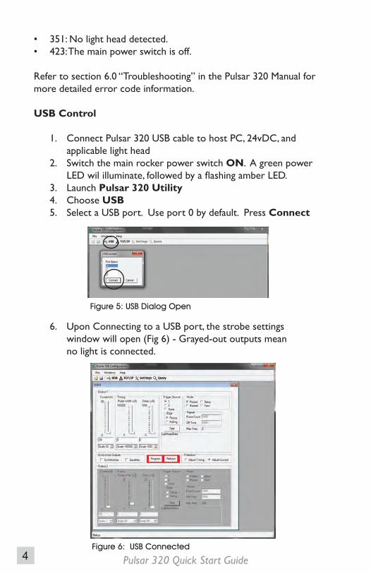
1. Connect Pulsar 320 USB cable to host PC, 24vDC, and applicable light head 2. Switch the main rocker power switch ON. A green power LED wil illuminate, followed by a flashing amber LED. 3. Launch Pulsar 320 Utility 4. Choose USB 5. Select a USB port. Use port 0 by default. Press Connect
6. Upon Connecting to a USB port, the strobe settings window will open (Fig 6) - Grayed-out outputs mean no light is connected.
Figure 6: USB Connected
Figure 5: USB Dialog Open
4
Pulsar 320 Quick Start Guide Pulsar 320 Quick Start Guide
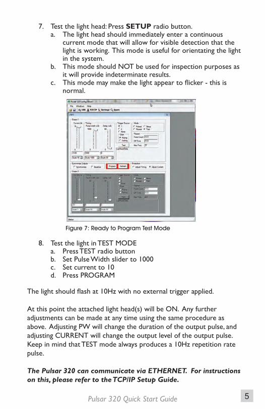
7. Test the light head: Press SETUP radio button. a. The light head should immediately enter a continuous current mode that will allow for visible detection that the light is working. This mode is useful for orientating the light in the system. b. This mode should NOT be used for inspection purposes as it will provide indeterminate results. c. This mode may make the light appear to flicker - this is normal.
8. Test the light in TEST MODE a. Press TEST radio button b. Set Pulse Width slider to 1000 c. Set current to 10 d. Press PROGRAM
The light should flash at 10Hz with no external trigger applied.
At this point the attached light head(s) will be ON. Any further adjustments can be made at any time using the same procedure as above. Adjusting PW will change the duration of the output pulse, and adjusting CURRENT will change the output level of the output pulse. Keep in mind that TEST mode always produces a 10Hz repetition rate pulse.
The Pulsar 320 can communicate via ETHERNET. For instructions on this, please refer to the TCP/IP Setup Guide.
Figure 7: Ready to Program Test Mode
5

Pulsar 320 Quick Start Guide