ptfe bellows & compensators - mersen · the compensators are fitted with standard flanges...
TRANSCRIPT

ARMYLOR ®
PTFE BELLOWS
& COMPENSATORS

CONTENT
MERSEN ANTICORROSION EQUIPMENT p.2
RANGE OF BELLOWS & COMPENSATORS p.3
REFERENCES p.4
TECHNICAL SPECIFICATIONS p.5-6
BELLOW FLANGES p.7
COMPENSATOR FLANGES p.8
STANDARD BELLOWS TYPE 207 p.9-10
REINFORCED BELLOWS TYPE 227 p.11-12
COMPENSATORS TYPE G283 p.13-14
MERSEN ANTICORROSION EQUIPMENT
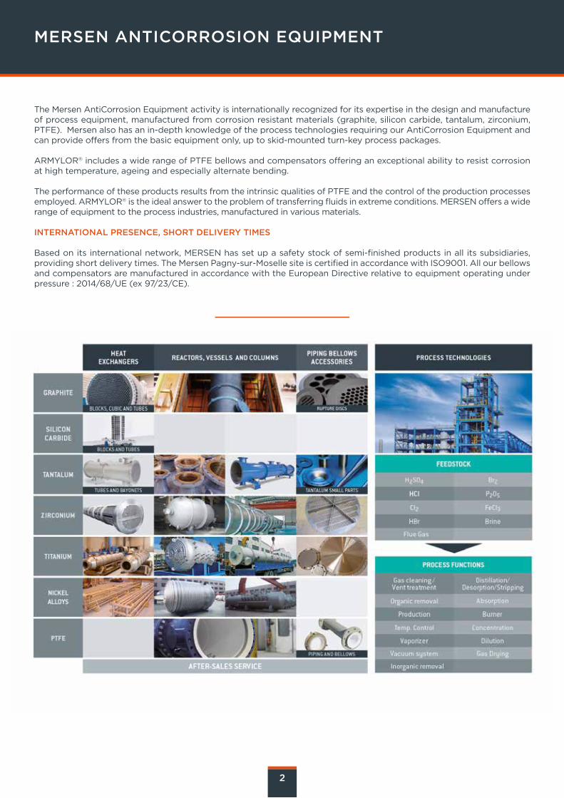
The Mersen AntiCorrosion Equipment activity is internationally recognized for its expertise in the design and manufacture of process equipment, manufactured from corrosion resistant materials (graphite, silicon carbide, tantalum, zirconium, PTFE). Mersen also has an in-depth knowledge of the process technologies requiring our AntiCorrosion Equipment and can provide offers from the basic equipment only, up to skid-mounted turn-key process packages.
ARMYLOR® includes a wide range of PTFE bellows and compensators offering an exceptional ability to resist corrosion at high temperature, ageing and especially alternate bending.
The performance of these products results from the intrinsic qualities of PTFE and the control of the production processes employed. ARMYLOR® is the ideal answer to the problem of transferring fluids in extreme conditions. MERSEN offers a wide range of equipment to the process industries, manufactured in various materials.
INTERNATIONAL PRESENCE, SHORT DELIVERY TIMES
Based on its international network, MERSEN has set up a safety stock of semi-finished products in all its subsidiaries, providing short delivery times. The Mersen Pagny-sur-Moselle site is certified in accordance with ISO9001. All our bellows and compensators are manufactured in accordance with the European Directive relative to equipment operating under pressure : 2014/68/UE (ex 97/23/CE).
2

The ARMYLOR® bellows and compensators compensate for thermal expansion in pipelines.
They are commonly used to protect fragile equipment (graphite, glass-lined equipment, plastic, etc.) or to absorb vibrations of equipment (pumps, etc.). Additionally ARMYLOR® bellows can be used in extreme corrosive or high-temperature conditions.
MERSEN offers a comprehensive range of expansion joints in ARMYLOR®.
RANGE OF BELLOWS & COMPENSATORS
STANDARD BELLOWS REINFORCED BELLOWS COMPENSATORS
TYPE 207
ARMYLOR® type 207 bellows,reinforced by stainless
steel rings, which fulfill therequirements of most pressure
applications.
TYPE 227
ARMYLOR® type 227 bellows,reinforced by stainless steel ringsand shells, which can withstandhigher pressure, whilst keeping
their flexibility.
TYPE 283
ARMYLOR® type 283compensators are externallyreinforced by a stainless steelhousing and allow operation
at very high pressure.
Operation in vacuum for types V207 and V227
3

REFERENCES
Each ARMYLOR® item has a reference which allows it to be defined.This reference is composed of 13 alphanumeric characters (C1 to C13).In certain cases, the criteria can be identified by a dash (-) if it corresponds to the standard.The references of the dimensional tables are those of standard construction.
4
Examples
Bellow, flange connection PN10, type 207,5 convolutions DN200.S1--207-5T
Bellows, connection 150 lbs, vacuum range, Antistatic PTFE, type 227, 3 convolutions, DN300, stainless steel flanges.S2VA227-3V--X
Examples of the reference in a table
PRODUCT REFERENCE
S
Bellows or compensators(according to specification)
CONNECTION
1 - 2 - 3 - 4 - 5…
Example :1=PN10, 2=PN20/150lbs
3=PN16, 4=300lbs, 5=PN40
RANGE
-Standard range
VVacuum range
SSpecial
PTFE LINING
-Virgin
AAntistatic
TYPE OF BELLOWS
207-3Type 207, 3 convolutions
227-3Type 227, 3 convolutions
Refer to corresponding page
C1 S S
C2 1 2
C3 - V
C4 - A
C5 2 2
C1 C2 C3 C4 C5 C6 C7 C8 C9 C10 C11 C12 C13
DIAMETER
For each diameter,corresponds a letter.
Refer to the table hereafter
For bellowsC11= --
LOOSE FLANGES
-0
STEEL PARTS
-Standard
RLow temperature
Carbon steel
XStainless steel
SSpecial
C6 0 2
C7 7 7
C8 - -
C9 5 3
C10 T V
C11 -
C12 -
C13 X
REFERENCES
CODIFICATIONREP
DIAMETERDN (MM)
H 15
J 20
K 25
L 32
M 40
N 50
O 65
P 80
Q 100
R 125
S 150
T 200
CODIFICATIONREP
DIAMETERDN (MM)
U 250
V 300
W 350
X 400
Y 450
Z 500
B 600
PTFE MEMBRANES
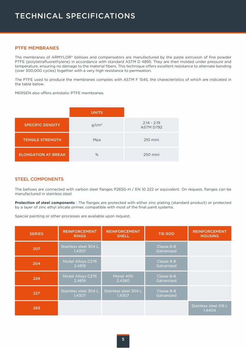
The membranes of ARMYLOR® bellows and compensators are manufactured by the paste extrusion of fine powder PTFE (polytetrafluorethylene) in accordance with standard ASTM D 4895. They are then molded under pressure and temperature, ensuring no damage to the material fibers. This technique offers excellent resistance to alternate bending (over 300,000 cycles) together with a very high resistance to permeation.
The PTFE used to produce the membranes complies with ASTM F 1545, the characteristics of which are indicated in the table below.
MERSEN also offers antistatic PTFE membranes.
STEEL COMPONENTS
The bellows are connected with carbon steel flanges P265G-H / EN 10 222 or equivalent. On request, flanges can be manufactured in stainless steel.
Protection of steel components : The flanges are protected with either zinc plating (standard product) or protected by a layer of zinc ethyl silicate primer, compatible with most of the final paint systems.
Special painting or other processes are available upon request.
TECHNICAL SPECIFICATIONS
5
UNITS
SPECIFIC DENSITY g/cm3 2.14 - 2.19ASTM D792
TENSILE STRENGTH Mpa 210 mini
ELONGATION AT BREAK % 250 mini
SERIESREINFORCEMENT
RINGSREINFORCEMENT
SHELLTIE ROD
REINFORCEMENT HOUSING
207Stainless steel 304 L
1.4307Classe 8-8 Galvanized
204Nickel Alloys C276
2.4819Classe 8-8 Galvanized
224Nickel Alloys C276
2.4819Monel 400
2.4360Classe 8-8 Galvanized
227Stainless steel 304 L
1.4307Stainless steel 304 L
1.4307Classe 8-8 Galvanized
283Stainless steel 316 L
1.4404

6
INSPECTION AND CONTROL, CERTIFICATES
All our products are inspected and controlled by our Quality Department in accordance with our ISO 9001 quality assurance system. Design and manufacturing control meet the requirement of the Pressure Equipment Directive PED 2014/68/UE (ex-97/23/CE ). Mersen can supply a Bureau Veritas certificate for marine offshore applications.
DESIGN
Flanges with plain connect the standard bellows.On request, the holes can be tapped.The compensators are fitted with standard flanges conforming to the type of drilling requested (PN or ANSI).The flanges have PN 10, PN 16, ANSI 150 Ibs or ANSI 300 Ibs drilling and other standards are available on request.The maximum operating pressure of the bellows and compensators must be in accordance with the respective pressure/temperature resistance performance curves.
INSTALLATION PROCEDURE
PrecautionsDo not remove the wooden plugs until the time of installation; once the plug is removed, great care must be taken toavoid damaging the PTFE.
CleaningThe sealing surfaces must be carefully cleaned before installation.
Bolt tighteningThe installation of ARMYLOR® bellows and compensators does not require any additional gasket, except when connecting to materials of a different nature or in the case of successive assembly and disassembly operations.
Bolt tightening Insert the washers Clean and grease the bolts Tighten the nuts manually Tighten each bolt with a torque wrench, respecting the tightening torques Tightening is carried out “crosswise”, as for any flange connection
The values of tightening torques are available in the assembly instructions delivered with the ARMYLOR® components.The tightening torques are at-cold values and must always be verified when the equipment is cold, after 24 hours of operation then periodically thereafter.
The tightening torque values indicated herein also apply to : Class 8.8 steel bolts (rupture resistance 800N/mm, limit of elasticity 640N/mm) A screw/nut coefficient of friction of 0.12
Bellows are delivered with limit bolts set at the maximum length. Limit bolts must not be removed otherwise bellows could exceed the maximum length.
All installation and operating instructions specified in the instructions supplied with the products.

BELLOW FLANGES
(*) Specific drilling upon request “X” stands for drillings “on axis / out of axis” “H” stands for drillings “on axis / on axis” [en] is the nominal thickness of PTFE liners
BELLOWSTYPES 207 - 227 DRILLING (*)
DN
(mm)
DN
(inches)
D
(mm)
K
(mm)
g
(mm)
e
(mm)
[en]
(mm)
Drilling
orientationPN 10 ASA 150 Lbs
20 ¾ " 105 155 43 10 2,5 X 4x dia 14 out of 75 mm 4x dia 16 out of 69 mm
25 1 " 115 160 52 12 2,5 X 4x dia 14 out of 85 mm 4x dia 16 out of 79,4 mm
32 1.¼" 140 190 62 12 3 X 4x dia 18 out of 100 mm 4x dia 16 out of 88,9 mm
40 1.½" 150 200 70 13 3 X 4x dia 18 out of 110 mm 4x dia 16 out of 98 ,4 mm
50 2" 165 220 90 16 3,5 X 4x dia 18 out of 125 mm 4x dia 20 out of 120,6 mm
65 2.½" 185 240 108 16 3 X 4x dia 18 out of 145 mm 4x dia 20 out of 139,7 mm
80 3" 200 255 122 16 3 H 8x dia 18 out of 160 mm 4x dia 20 out of 152,4 mm
100 4" 230 290 148 16 3,5 H 8x dia 18 out of 180 mm 8x dia 20 sur 190,5 mm
125 5" 255 3 15 174 18 4 H 8x dia 18 out of 210 mm 8x dia 23 out of 215,9 mm
150 6" 285 345 200 18 4 H 8x dia 22 out of 240 mm 8x dia 23 out of 241,3 mm
200 8" 345 405 256 20 4 H 8x dia 22 out of 295 mm 8x dia 23 out of 298,4 mm
250 10" 410 470 303 25 4 H 12x dia 22 out of 350mm 12x dia 26 out of 361,9 mm
300 12" 485 545 353 25 4 H 12x dia 22 out of 400 mm 12x dia 26 out of 431,8 mm
350 14" 535 595 402 27 4,5 H 16x dia 22 out of 460 mm 12x dia 29 out of 476,2 mm
400 16" 600 660 453 26 4 H 16x dia 26 out of 515 mm 16x dia 29 out of 539,8 mm
450 18" 640 695 513 28 3,5 H 20x dia 26 out of 565 mm 16x dia 32 out of 577,8 mm
500 20" 700 760 564 30 4 H 20x dia 26 out of 620 mm 20x dia 32 out of 635 mm
600 24" 818 885 658 32 4 H 20x dia 30 out of 725 mm 20x dia 35 out of 749,3 mm
7
ØK ØD
e
[en]
g

COMPENSATOR FLANGES
COMMON CHARACTERISTICS DRILLING PN10 DRILLING ANSI 150
DN
(mm)
DN
(inches)
en
(mm)
g
(mm)
D
(mm)
e
(mm)
D
(mm)
e
(mm)
50 2" 3,5 98 165 18 152,4 22
65 2.½" 3 118 185 18 177,8 24
80 3" 9 127 200 22 190,5 24
100 4" 3,5 158 230 22 228,6 24
125 5" 4 188 255 24 254 24
150 6" 4 212 285 24 279,4 25
200 8" 4 268 345 24 342,9 29
250 10" 4 320 410 26 106,4 30
300 12" 4 370 485 26 482,6 32
350 14" 4,5 430 535 28 533,4 35
400 16" 4,5 480 600 32 596,9 36,5
450 18" 3,5 532 640 38 635 40
500 20" 4 585 700 38 698,5 43
600 24" 4 685 815 40 812,8 48
8
ØD
e
g

STA NDARD BELLOWS TYPE 207RANGES G (STANDARD) AND V (VACUUM)
9
AVAILABILITY REFERENCES
DN
mm
DN
inches
NberConvo-lutions
L
mm
∆ x
mm
∆ y
mm
Fx DaN/
mm
Fy DaN/
mm
Weight
kg
Range
G
Range
VC1 C2 C3 C4 C5 C6 C7 C8 C9 C10
20 ¾" 3 50 10 8 4,5 2 2,5 S x - - 2 0 7 - 3 J
25 1" 3 50 12 10 4,5 2 2,5 S x - - 2 0 7 - 3 K
5 75 20 15 4 1,5 2,8 S x - - 2 0 7 - 5 K
32 1.¼" 3 50 12 12 5 2,5 3 S x - - 2 0 7 - 3 L
5 75 20 18 4 2 3,5 S x - - 2 0 7 - 5 L
40 1.½" 3 50 12 15 5 2,8 4 S x - - 2 0 7 - 3 M
5 75 20 20 4 2 4,5 S x - - 2 0 7 - 5 M
50 2" 3 75 15 15 5 4,5 6 S x - - 2 0 7 - 3 N
5 100 25 20 4 3,5 6,5 S x - - 2 0 7 - 5 N
65 2.½" 3 75 22 17 4 5 7 S x - - 2 0 7 - 3 O
5 100 35 30 3,5 4 7,5 S x - - 2 0 7 - 5 O
80 3" 3 100 25 17 4 6 8 S x - - 2 0 7 - 3 P
5 125 40 30 3,5 4,5 9 S x - - 2 0 7 - 5 P
100 4" 3 100 25 17 5 9 10 S x - - 2 0 7 - 3 Q
5 150 40 30 3,5 6 11 S x - - 2 0 7 - 5 Q
125 5" 3 125 28 18 6 11 12 S x - - 2 0 7 - 3 R
5 175 45 32 4 8 13 S x - - 2 0 7 - 5 R
150 6" 3 150 28 18 10 15 15 S x - - 2 0 7 - 3 S
5 225 45 32 8 12 17 S x - - 2 0 7 - 5 S
200 8" 3 150 28 20 15 18 20 S x - - 2 0 7 - 3 T
5 225 45 32 10 15 22 S x - - 2 0 7 - 5 T
250 10" 3 150 28 10 15 20 35 S x - - 2 0 7 - 3 U
5 225 45 15 10 17 37 S x - - 2 0 7 - 5 U
300 12" 3 150 30 8 15 20 48 S x - - 2 0 7 - 3 V
5 225 50 10 12 17 50 S x - - 2 0 7 - 5 V
350 14" 3 150 30 6 20 27 57 S x - - 2 0 7 - 3 W
5 225 50 8 16 23 59 S x - - 2 0 7 - 5 W
400 16" 3 150 30 6 20 27 70 S x - - 2 0 7 - 3 X
5 225 50 8 16 23 72 S x - - 2 0 7 - 5 X
450 18" 3 150 30 5 25 29 78 S x - - 2 0 7 - 3 Y
5 225 50 7 20 24 80 S x - - 2 0 7 - 5 Y
500 20" 3 150 30 5 30 35 86 S x - - 2 0 7 - 3 Z
5 225 50 7 25 30 89 S x - - 2 0 7 - 5 Z
600 24" 3 175 30 4 30 35 125 S x - - 2 0 7 - 3 B
5 250 50 6 25 30 130 S x - - 2 0 7 - 5 B
750 30 3 190 30 4 30 35 200 S x - - 2 0 7 - 3 ZE
900 36 3 215 30 3 30 35 300 S X - - 2 0 7 - 3 ZH
1050 42 3 240 30 2 30 35 730 S X - - 2 0 7 - 3 ZK
L is the dimension to be obtained at Installation (neutral length)
Fx and Fy are the forces of compression and offset in daN for an axial movement ∆x = 1 mm or a misalignment ∆y = 1 mm
C2 : x on the column must be filled in according to your specifications: 1 = PN10, 2 = 150 lbs, etc.
C3 : - (here in standard). The vacuum option V is only available for 3 convolutions bellows
CHARACTERISTICS

PRESSURE RESISTANCERanges G (standard) and V (Vacuum) – 3 convolutions
VACUUM RESISTANCERange G (standard)
10
250
200
150
100
50
0
0 1 2 3 4 5 6 7 8 9 10
For G 5 convolutions standard bellow, the values of vacuum and pressure resistance must be multiplied by 0.5
The vacuum resistance of G207 bellows from DN20 to DN50 together with V207 bellows is 2 Torr up to 180°C
DN750, 900 and 1050 are available upon request
For operation in corrosive environment, MERSEN offers serie 204 bellows with nickel alloys C 276 rings.
The characteristics and sizes of the type 204 bellows are identical to those of type 207
220
200
180
160
140
120
100
80
60
40
20
°C
g
BarA B C D E F
1 2 3 4 5 6 7 8 9 10
220
200
180
160
140
120
100
80
60
40
20
°C
Torr
ABC
DEF
100 200 300 400 500 600 700 760
RANGE
THE PERFORMANCE CURVES
Bellow Standard Range G2073 and 5 convolutions
Bellow Range Vacuum V207Available only with 3 convolutions
L
Outside reinforcement ringsOutside reinforcement
ringsVacuum resistance
rings
L
CURVES DN (mm)
A 500 & 600
B 400 & 450
C 300 & 350
D 200 & 250
E 100 & 150
F 25 à 80
Bar
C°DN 750 - 900 - 1050 PRESSURE RESISTANCE
(RANGE G & V) - 3 WAVES

REINFORCED BELLOWS TYPE 227RANGE G (STANDARD) AND V (VACUUM)
11
AVAILABILITY REFERENCES
DN
mm
DN
inches
NberConvo-lutions
L
mm
∆ x
mm
∆ y
mm
Fx DaN/
mm
Fy DaN/
mm
Weight
kg
Range
G
Range
VC1 C2 C3 C4 C5 C6 C7 C8 C9 C10
25 1" 3 50 7 4 4,5 2 2,5 S x - - 2 2 7 - 3 K
32 1.¼" 3 50 7 4 5 2,5 3 S x - - 2 2 7 - 3 L
40 1.½" 3 50 7 5 5 2,8 4 S x - - 2 2 7 - 3 M
50 2" 3 75 8 5 5 4,5 6,5 S x - - 2 2 7 - 3 N
65 2.½" 3 75 10 5 4 5 7,5 S x - - 2 2 7 - 3 O
80 3" 3 100 15 8 4 6 8,5 S x - - 2 2 7 - 3 P
100 4" 3 100 15 8 5 9 11 S x - - 2 2 7 - 3 Q
125 5" 3 125 20 10 6 11 13 S x - - 2 2 7 - 3 R
150 6" 3 150 28 10 10 15 16 S x - - 2 2 7 - 3 S
200 8" 3 150 28 10 15 18 21 S x - - 2 2 7 - 3 T
250 10" 3 150 28 10 15 20 36 S x - - 2 2 7 - 3 U
300 12" 3 150 30 8 15 20 49 S x - - 2 2 7 - 3 V
350 14" 3 150 30 6 20 27 58 S x - - 2 2 7 - 3 W
400 16" 3 150 30 6 20 27 72 S x - - 2 2 7 - 3 X
450 18" 3 150 30 5 25 29 80 S x - - 2 2 7 - 3 Y
500 20" 3 150 20 5 30 35 89 S x - - 2 2 7 - 3 Z
600 24" 3 175 20 4 30 35 130 S x - - 2 2 7 - 3 B
L is the dimension to be obtained during installation (neutral length)
Fx and Fy are the forces of compression and offset in daN for an axial movement ∆x = 1 mm or a misalignment ∆y = 1 mm
C2 : x on the column must be filled in according to your specifications : 1 = PN10, 2 = 150 lbs, etc.
C3 : - (here in standard). The vacuum option V is only available for 3 convolutions bellows
For operation in corrosive environment, MERSEN offers serie 224 bellows with nickel alloys C 276 and MONEL 400 shellsThe characteristics and the dimensions of type 224 bellows are identical to those of 227
CHARACTERISTICS

12
G Bellows from DN25 to DN50 withstandvacuum resistance of 2 Torr at 180°C
The vacuum resistance of V227 bellowsis 2 Torr up to 180°C
220
200
180
160
140
120
100
80
60
40
20
°C
g
BarA B C D E F
1 2 3 4 5 6 7 8 9 10 11
220
200
180
160
140
120
100
80
60
40
20
°C
Torr
ABC
DEF
100 200 300 400 500 600 700 760
RANGE
PERFORMANCE CURVES
CURVES DN (mm)
A 500 & 600
B 400 & 450
C 300 & 350
D 200 & 250
E 100 & 150
F 25 à 80
BELLOW RANGE VACUUM V227
3 convolutions only
Outside reinforcementrings
Reinforcementshells
L
Rings for vacumresistance
PRESSURE RESISTANCERange G (standard) and V (Vacuum) – 3 convolutions
VACUUM RESISTANCERange G (standard)
BELLOW STANDARD RANGE G227
3 convolutions only
Outside reinforcementrings
Reinforcementshells
L

COMPENSATORS TYPE G 283
13
REFERENCES
DN
mm
DN
inches
L
mm
± ∆ x
mm
± ∆ y
mm
Fx DaN/
mm
Fy DaN/
mm
Weight
kgC1 C2 C3 C4 C5 C6 C7 C8 C9 C10
50 2" 150 3.5 2.5 14.2 9.6 5,5 S x - - 2 8 3 - - N
80 3" 150 4 2 22.8 26 7,5 S x - - 2 8 3 - - P
100 4" 150 5 2 48.1 51.9 8,5 S x - - 2 8 3 - - Q
125 5" 150 5 2 137.2 361.3 11 S x - - 2 8 3 - - R
150 6" 195 11 4 48.2 122.8 13 S x - - 2 8 3 - - S
200 8" 245 14 4.5 77.4 126.4 20 S x - - 2 8 3 - - T
250 10" 245 17 6 55.1 142.1 27 S x - - 2 8 3 - - U
300 12" 400 24 13 81.1 68.9 41 S x - - 2 8 3 - - V
350 14" 400 39 19 52.7 60.3 55 S x - - 2 8 3 - - W
400 16" 400 42 18 49.2 73.7 75 S x - - 2 8 3 - - X
450 18" 400 36 14 50 110.6 80 S x - - 2 8 3 - - Y
500 20" 400 36 13 48.30 129.9 100 S x - - 2 8 3 - - Z
600 24" 400 36 11 51.8 198.6 120 S x - - 2 8 3 - - B
C2 : x on the column must be filled in according to your specifications: 1 = PN10, 2 = 150 lbs, etc..
In contrast to bellows, MERSEN compensators are not equipped with limit bolts.
CHARACTERISTICS
The specification or data herein contained are only given for indication, without any undertakings whatsoever. Their publication does not suggest the matter is free of any rights whatsoever. Furthermore, due to constant evolution of techniques and norms, we reserve the right to modify, at any time, the characteristics and specifications contained in this document. MERSEN refuses all and any responsibility concerning their use whatever the purpose or application. Any copy, reproduction or information herein contained, in whole or in part, made without MERSEN written consent, is forbidden according to the laws of France and particularly the law nr. 92-597 of July 1st 1992 relating to the copyright.
14
Warning: Design pressures of flanges must be lower than operating pressures of membranes as shown by the performance curves.The maximum operating pressures of compensators are limited to their flanges pressures design.
220
200
180
160
140
120
100
80
60
40
20
°C
A
B
CDE
100 200 300 400 500 600 700 760
Torr
220
200
180
160
140
120
100
80
60
40
20
°C
10 11 12 13 14 15 16 17 18 19 20 21 22 23 24 25 26 27 28 2930
BarA B E C D
PRESSURE RESISTANCE VACUUM RESISTANCE
CURVES DN (mm)
A 500 & 600
B 300 & 450
C 200 & 250
D 100 & 150
E 50 & 80
RANGE
PERFORMANCE CURVES
COMPENSATOR G283

B16
_5
_E
| d
esig
n g
rap
hiq
ue
: A
GE
NC
E B
ER
LIO
Z
G LO B A L E X P E R T I N E L E C T R I C A L
P OW E R A N D A DVA N C E D M AT E R I A L S