pspice seminar
TRANSCRIPT
NAGPUR INSTITUTE OF TECHNOLOGY,NAGPUR
DEPARTMENT OF COMPUTER SCI.&
ENGINEERING
MASTERS OF ENGINEERING
In
Embedded system & Computing
SESSION 2013-2014
M.E.- II SEMESTER
A
Presentation On
“PSPICE”
By:
Ms. Ayushi S. Jaiswal
Guided By:
Prof. Shubhangi Borkar
(Computer Sci.& Engineering)
Introduction to PSPICE
Simulation Program with Integrated Circuit Emphasis
◦ Developed in 1970’s at Berkeley
◦ Many commercial versions are available
◦ HSPICE is a robust industry standard
SPICE is a general purpose analog circuit simulator that is used to verify circuit designs and to predict the circuit behaviour.
PSpice is a PC version of SPICE that runs on workstations and larger computers.
PSPICE Overview
OrCAD PSpice simulates analog-only circuits.
After we prepare a design for simulation, OrCAD Capture generates a circuit file set.
The circuit file set, containing the circuit netlist and analysis commands, is read by PSpice for simulation.
PSpice formulates these into meaningful graphical plots, which you can mark for display directly from your schematic page using markers.
Circuit Components available
Independent and dependent voltage and current sources
Resistors
Inductors
Mutual inductors
Transmission lines
Operational amplifiers
Switches
Diodes
Bipolar transistors
MOS transistors
JFET
MOSFET
Digital gates
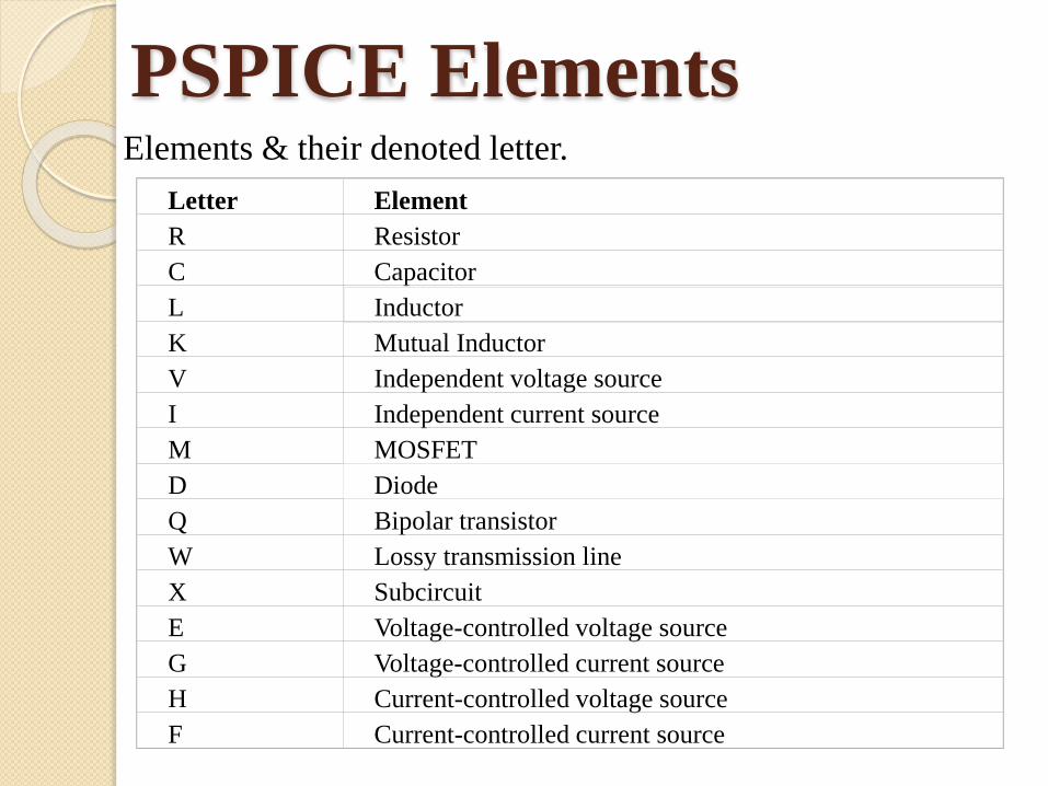
PSPICE Elements Elements & their denoted letter.
Letter Element
R Resistor
C Capacitor
L Inductor
K Mutual Inductor
V Independent voltage source
I Independent current source
M MOSFET
D Diode
Q Bipolar transistor
W Lossy transmission line
X Subcircuit
E Voltage-controlled voltage source
G Voltage-controlled current source
H Current-controlled voltage source
F Current-controlled current source
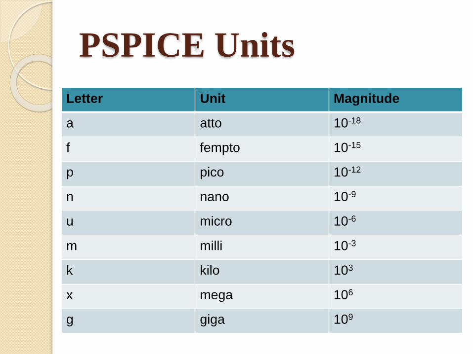
PSPICE Units
Letter Unit Magnitude
a atto 10-18
f fempto 10-15
p pico 10-12
n nano 10-9
u micro 10-6
m milli 10-3
k kilo 103
x mega 106
g giga 109
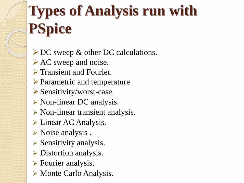
Types of Analysis run with
PSpice
DC sweep & other DC calculations.
AC sweep and noise.
Transient and Fourier.
Parametric and temperature.
Sensitivity/worst-case.
Non-linear DC analysis.
Non-linear transient analysis.
Linear AC Analysis.
Noise analysis .
Sensitivity analysis.
Distortion analysis.
Fourier analysis.
Monte Carlo Analysis.
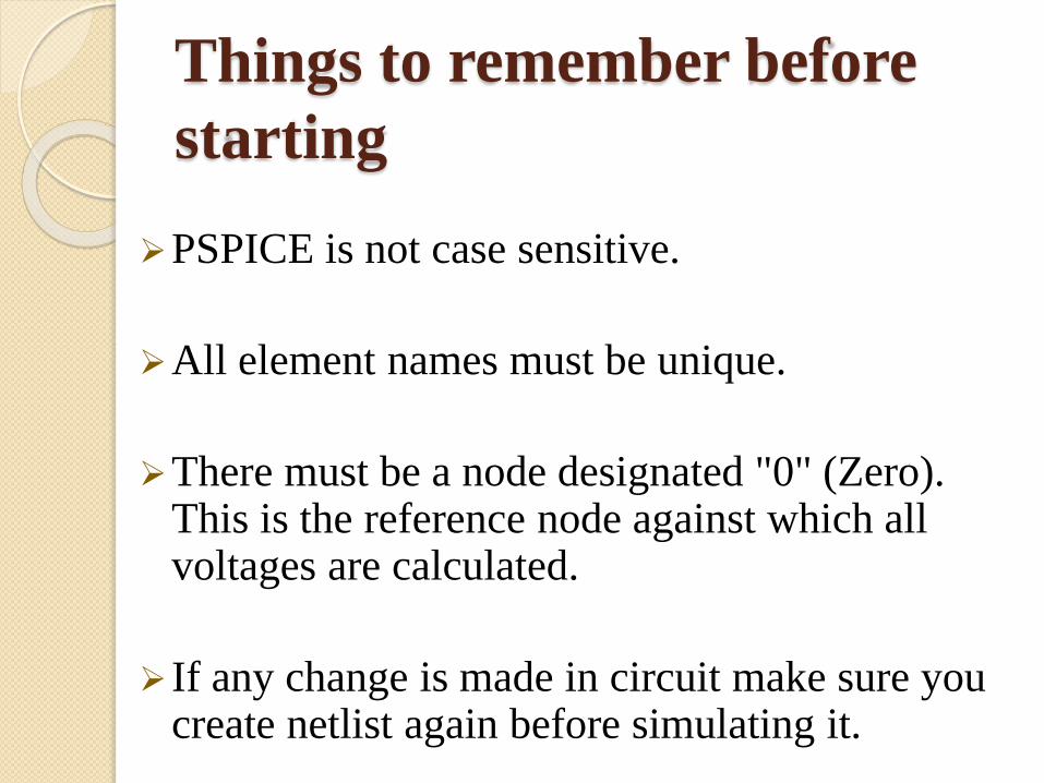
Things to remember before
starting
PSPICE is not case sensitive.
All element names must be unique.
There must be a node designated "0" (Zero). This is the reference node against which all voltages are calculated.
If any change is made in circuit make sure you create netlist again before simulating it.
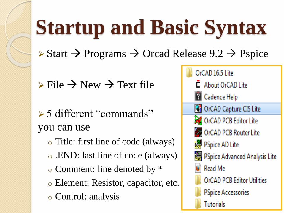
Startup and Basic SyntaxStart Programs Orcad Release 9.2 Pspice
File New Text file
5 different “commands”
you can use
o Title: first line of code (always)
o .END: last line of code (always)
o Comment: line denoted by *
o Element: Resistor, capacitor, etc.
o Control: analysis
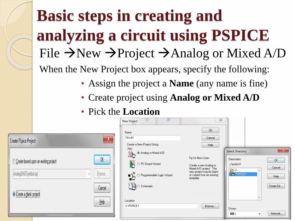
Basic steps in creating and
analyzing a circuit using PSPICE File New Project Analog or Mixed A/D
When the New Project box appears, specify the following:
• Assign the project a Name (any name is fine)
• Create project using Analog or Mixed A/D
• Pick the Location
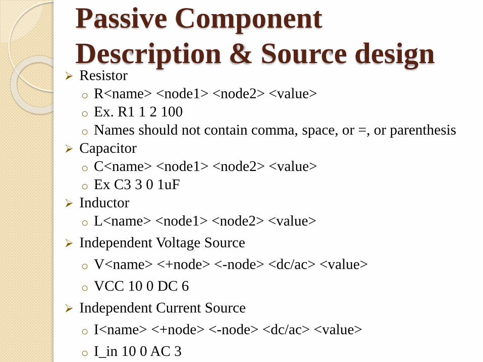
Passive Component
Description & Source design Resistor
o R<name> <node1> <node2> <value>
o Ex. R1 1 2 100
o Names should not contain comma, space, or =, or parenthesis
Capacitor
o C<name> <node1> <node2> <value>
o Ex C3 3 0 1uF
Inductor
o L<name> <node1> <node2> <value>
Independent Voltage Source
o V<name> <+node> <-node> <dc/ac> <value>
o VCC 10 0 DC 6
Independent Current Source
o I<name> <+node> <-node> <dc/ac> <value>
o I_in 10 0 AC 3
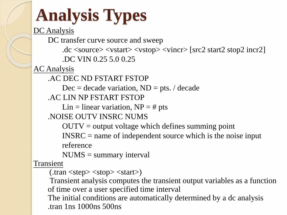
Analysis TypesDC Analysis
DC transfer curve source and sweep
.dc <source> <vstart> <vstop> <vincr> [src2 start2 stop2 incr2]
.DC VIN 0.25 5.0 0.25
AC Analysis
.AC DEC ND FSTART FSTOP
Dec = decade variation, ND = pts. / decade
.AC LIN NP FSTART FSTOP
Lin = linear variation, NP = # pts
.NOISE OUTV INSRC NUMS
OUTV = output voltage which defines summing point
INSRC = name of independent source which is the noise input
reference
NUMS = summary intervalTransient
(.tran <step> <stop> <start>)Transient analysis computes the transient output variables as a function of time over a user specified time interval The initial conditions are automatically determined by a dc analysis .tran 1ns 1000ns 500ns
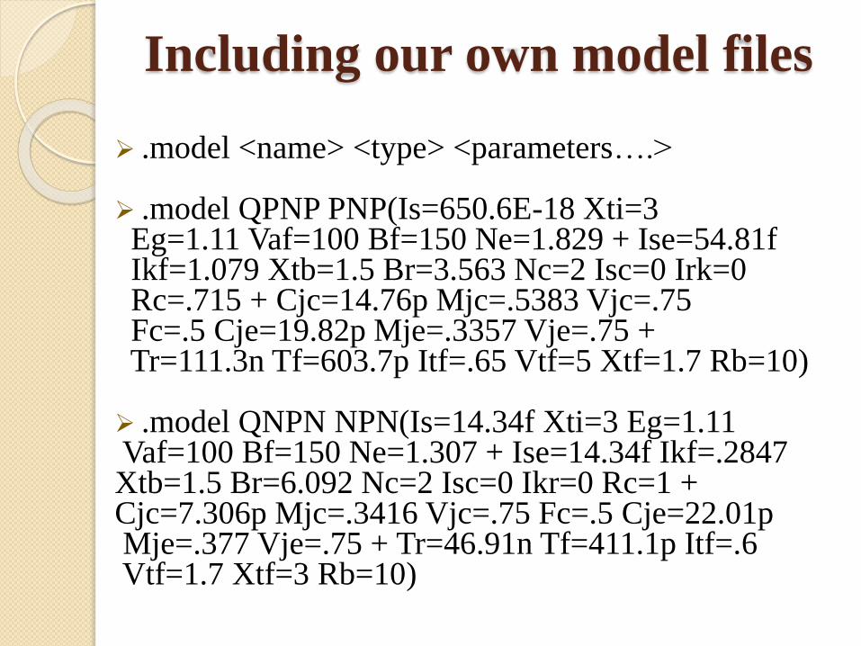
Including our own model files
.model <name> <type> <parameters….>
.model QPNP PNP(Is=650.6E-18 Xti=3 Eg=1.11 Vaf=100 Bf=150 Ne=1.829 + Ise=54.81fIkf=1.079 Xtb=1.5 Br=3.563 Nc=2 Isc=0 Irk=0Rc=.715 + Cjc=14.76p Mjc=.5383 Vjc=.75 Fc=.5 Cje=19.82p Mje=.3357 Vje=.75 + Tr=111.3n Tf=603.7p Itf=.65 Vtf=5 Xtf=1.7 Rb=10)
.model QNPN NPN(Is=14.34f Xti=3 Eg=1.11Vaf=100 Bf=150 Ne=1.307 + Ise=14.34f Ikf=.2847 Xtb=1.5 Br=6.092 Nc=2 Isc=0 Ikr=0 Rc=1 + Cjc=7.306p Mjc=.3416 Vjc=.75 Fc=.5 Cje=22.01pMje=.377 Vje=.75 + Tr=46.91n Tf=411.1p Itf=.6Vtf=1.7 Xtf=3 Rb=10)
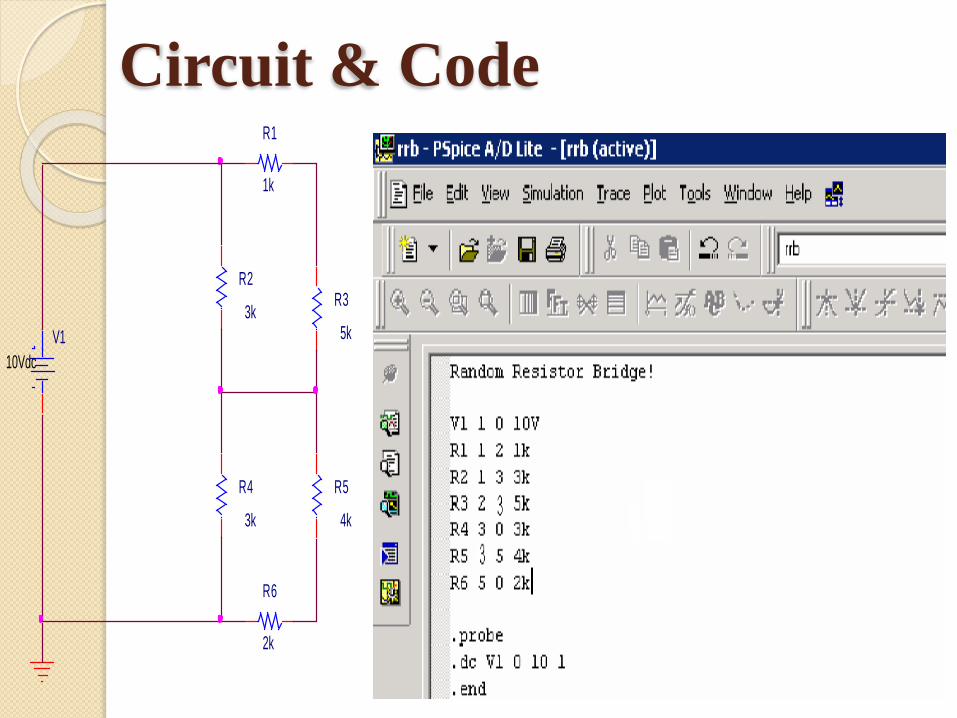
Circuit & Code
R3
5kV1
10Vdc
R5
4k
R4
3k
R6
2k
R2
3k
R1
1k
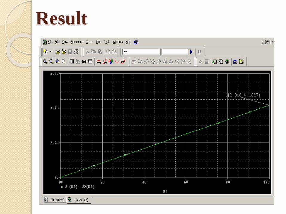
Result
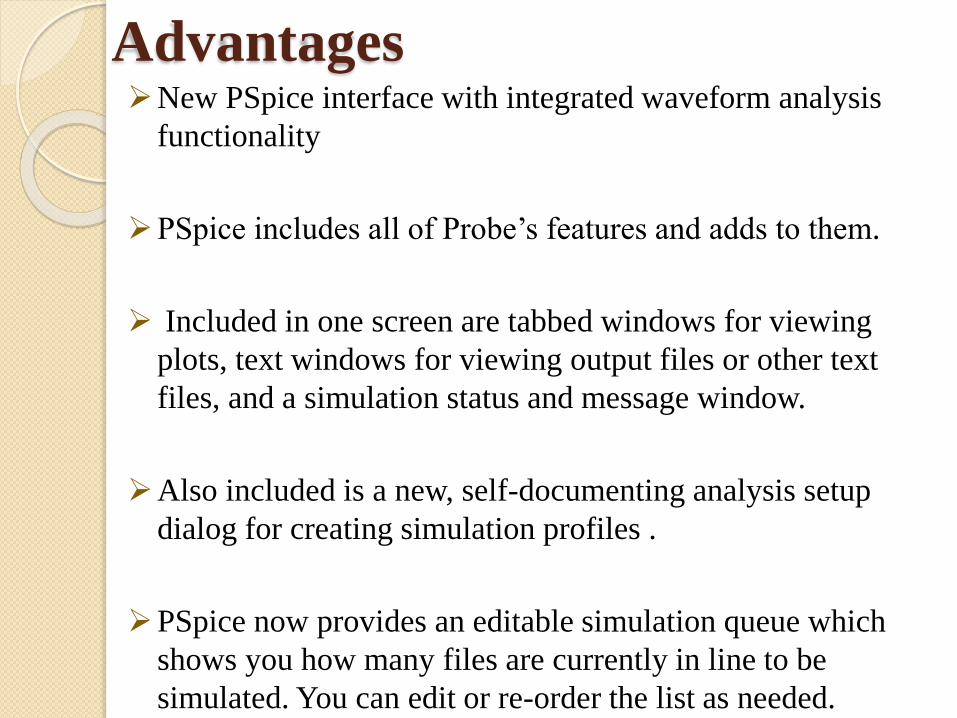
AdvantagesNew PSpice interface with integrated waveform analysis
functionality
PSpice includes all of Probe’s features and adds to them.
Included in one screen are tabbed windows for viewing
plots, text windows for viewing output files or other text
files, and a simulation status and message window.
Also included is a new, self-documenting analysis setup
dialog for creating simulation profiles .
PSpice now provides an editable simulation queue which
shows you how many files are currently in line to be
simulated. You can edit or re-order the list as needed.

THANK YOU