ps-pro ii - power conditioner / sequencer · ps-pro ii - power conditioner / sequencer front panel...
TRANSCRIPT

PS-PRO I I - POWER CONDIT IONER / SEqu ENCER
PS-PRO I I - POWER CONDIT IONER / SEqu ENCER
FEaTuRES
n SMP+ (Series Multi-Stage Protection Plus) non-sacrificial surge suppression — the most comprehensive protection available anywhere!
n LiFT (Linear Filtering Technology) with zero ground contamination
n Extreme voltage shutdown
n BNC connector on the rear panel al-lows for attachment of a gooseneck lamp to illuminate the rear of your rack
n Power Status LED’s indicate which outlet groups have power
n Remote operation allows turn-on and turn-off at a distance simply by con-necting a momentary or maintained-contact switch (and LED if desired)
n Multiple units may be linked to handle higher currents and/or more than three delay groups
n Six switched outlets (on rear panel), and three unswitched outlets (one front, two rear)
n Ten foot 12 AWG heavy duty power cord
n Three year limited warranty
INTRODuCTION
Thank you for purchasing the PS-PRO II, and congratulations on your choice. The Series II power conditioners feature Furman’s revolution-ary Series Multi-Stage Protection Plus (SMP+) circuit, as well as our exclusive Linear Filtering Technology (LiFT). Together, these technologies comprise, without question, the world's most advanced and comprehensive transient voltage surge suppressor / conditioner.
SMP+ (Series Multi-Stage Protection Plus)Furman’s SMP+ surge suppression virtually eliminates service calls. Traditional surge sup-pression circuits “sacrifice” themselves when exposed to multiple transient voltage spikes, re-quiring the dismantling of your system and repair of your surge suppressor. With Furman’s SMP+, however, damaging transient voltages are safely absorbed, clamped, and dissipated.
Unique to Furman’s SMP+ is its unparalleled clamping voltage. While other designs offer clamping voltages that are well above 330 Vpk, SMP+ clamps at 188 Vpk, (133 VAC RMS). This unprecedented level of protection is only available with Furman’s SMP+ technology. Ad-ditionally, Furman’s trusted over-voltage circuitry protects against all too frequent accidental con-nections to 208 or 240 VAC, by shutting off the incoming power until the over voltage condition is corrected.[For E versions: Furman’s SMP+ clamps at 376 VpK, (266 VAC RMS.)]
1
PS-PRO I I - POWER CONDIT IONER / SEqu ENCER
lIFT (linear filtering
technology)
Unfortunately, traditional AC filter - conditioners have been designed for unrealistic laboratory conditions. Prior technologies, whether multiple pole filter or conventional series mode, could actually harm audio and video performance more than they help, due to the resonant peaking of their antiquated, non-linear designs. Under certain conditions, these designs can actually add more than 10 dB of noise to the incoming AC line! Worse still, lost digital data, the need to re-boot digital pre-sets, or destroyed digital converters are frequently caused by excessive voltage spikes and AC noise contaminating the equipment ground. Furman’s SMP+ with LiFT takes another approach, ensuring optimal per-formance through linear filtering and no leakage to ground.
DESCRIPTION
The PS-PRO II is a power sequencer, meaning it is capable of powering a rack full of equipment in three steps separated by timed delays. It is use-ful whenever various kinds of equipment must be powered up or down in groups, rather than simultaneously. In audio systems, sequenced powering is often necessary to allow turn-on transients from low level amplifiers and pro-cessors to settle down before any power amps are turned on, because simultaneous powering would result in a loud, annoying, and potentially destructive “pop” reaching the speakers. And in any large system whose components present an inductive load to the AC line (including electric motors, power supplies, and power amplifiers of all kinds), sequenced powering can avoid excessive inrush currents that can cause circuit breakers to trip, even though the steady-state currents are not excessive. Power sequencing
is particularly suited to applications where large installations must be switched by inexperienced personnel.
The PS-PRO II is controlled by a front panel key-operated switch to provide security from non-authorized users tampering with the sys-tem. The switch has three positions: OFF, ON, and REM, allowing for local or remote control. With remote control, one or more PS-PRO II’s may be installed in remote locations with on/off control and LED monitoring via low-voltage control wires.
Besides its power sequencing capabilities, the PS-PRO II contains many other conditioning and protection features. Each aspect of its functioning will be discussed in the next sections.
INSTallaTION
RECOmmENDaTIONS
In audio/video installations, we recommend that power amps receive power last — plug them all into Delay 3 or divide them into two groups and plug one group through Delay 2 and the other through Delay 3. Low level equipment such as mixers and signal processors should use Delay 1. Equipment incorporating clocks or timers such as VCR’s, or equipment that must respond to wireless remote actuation, should use the un-switched outlets. We suggest keeping the front panel's unswitched outlet free for equipment that is only in use temporarily.
The overall capacity of the PS-PRO II is 20 amps. This refers to the combined steady-state current drawn by all devices plugged into all of its nine outlets. If this combined current level exceeds 20 amps at any time, the circuit breaker will trip, cutting off power to your rack. If this occurs, you must reduce the load by unplugging one or more units from the PS-PRO II. Then push the black button on the circuit breaker (on the front panel) to reset it.
2
PS-PRO I I - POWER CONDIT IONER / SEqu ENCER
front panel Delay Adjust control.
The Delay Adjust control, which can be set us-ing a screwdriver, controls the total delay time between Delay 2 and Delay 3. For example, if the Delay Adjust is set for 30 seconds, the De-lay 1 outlets will go on immediately, Delay 2 will power 15 seconds later and Delay 3 will power 15 seconds after Delay 2, for a total delay time of 30 seconds.
The order is reversed for the OFF sequence. For example, when an OFF sequence is initiated and the Delay Adjust control is set at 60 seconds, Delay 3 outlets lose power immediately, Delay 2 outlets lose power 30 seconds later and Delay 1 outlets lose power 30 seconds after Delay 2. The total delay time is 60 seconds.
In the event of a power outage, of course all equipment plugged into a PS-PRO II will lose power simultaneously. However, when power is restored, the delayed outlet groups will again turn on in the usual delayed sequence (if set to maintained on mode).
ON or OFF
SEquENCINg
The method of initiating an ON or OFF sequence depends on whether the unit is to be controlled locally or remotely. If remotely, it further depends on the type of switch or switches used (momentary or maintained).
LOCAL CONTROLFor local control, an ON sequence is initiated by turning the key switch to the ON position, and an OFF sequence by turning the key switch to OFF position. The START ON-OFF SEQUENCE pushbutton is not normally used in local operation.
NOTE: If the PS-PRO II is to be used under
Although 20 amps is an absolute limit, the PS-PRO II will allow you to come as close as possible to using the full 20 amps, because with power sequencing, the risk of tripping the breaker is greatly reduced. The PS-PRO II handles large but temporary inrush currents in stages, rather than simultaneously, allowing each stage to settle to its steady-state current draw before the next stage is powered.
Outlets and Plugs: The PS-PRO II’s four rear panel outlet pairs are standard 120V, 20A duplex types. These outlets are widely spaced, to ac-commodate one bulky plug-mounted “wall wart” power supply in each without covering up an adjacent outlet. The front panel outlet is limited to 15 amp use. The PS-PRO II also uses a 20 amp line cord, identified by the perpendicular blades on the plug. In 20 amp products, use of a plug of this type is required for UL safety certification. It is compatible with 20 amp outlets (such as those on the rear panel of the PS-PRO II). For more information about 20 amp plugs, see the information sheet “What Kind Of Plug Is This, Anyway?” accompanying this manual, or request a copy from Furman.
POWER
SEquENCINg
FEaTuRES
The PS-PRO II rear panel provides one un-switched and three switched outlet pairs. The switched outlet pairs are labeled Delay 1, Delay 2, and Delay 3. (The other pair of outlets on the rear panel and an additional single outlet on the front panel are unswitched.)
Here’s how the PS-PRO II works: When an ON sequence is initiated, power is immediately applied to the Delay 1 outlets. Power is then applied to Delay 2 and Delay 3 outlets per the 1-60 second total delay setting selected with the
3
PS-PRO I I - POWER CONDIT IONER / SEqu ENCER
local control only, and a jumper is installed on JMP1 with no switch connected to the PS-PRO II’s terminal strip, then a jumper should be connected between the REM and +12V terminals. Otherwise, turning the front panel key switch to the REM position will turn the PS-PRO II ON.
REMOTE CONTROLWhen the PS-PRO II’s front panel key lock switch is in the REM position, it can be controlled by one or more switches in remote locations. In the most basic configuration, only two wires and an SPST switch are needed to initiate an ON or OFF sequence. The switch may be either a momentary or a maintained-contact type, depending on a jumper setting inside the PS-PRO II. If an additional wire is used, an LED may also be installed at the remote end to indicate that the power is on.
MOMENTARy vs. MAINTAINED CONTACT SWITCHINGAn on-off switch of either kind may be used to actuate the PS-PRO II’s remote operation. Maintained switches, such as most toggle switches and push-on/push-off button switches, (including the Furman RS-1 key lock switch), stay open until switched, and then remain closed until switched again. Momentary switches, usually pushbutton types like the Furman RS-2 (which also provides a locking key switch), are normally open and stay closed only as long as the button is pressed.
Maintained switches are generally the most convenient when there is only one remote location. When more than one location is required, momentary switches offer the advantage of a turn-on or turn-off sequence which may be started from any location.
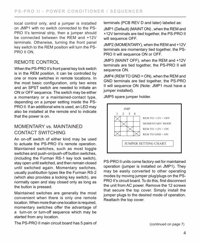
The PS-PRO II main circuit board has 5 pairs of
terminals (PCB REV D and later) labeled as:
JMP1 (Default) (MAINT ON) , when the REM and +12V terminals are tied together, the PS-PRO II will sequence OFF.
JMP2 (MOMENTARy), when the REM and +12V terminals are momentary tied together, the PS-PRO II will sequence ON or OFF.
JMP3 (MAINT OFF), when the REM and +12V terminals are tied together, the PS-PRO II will sequence ON.
JMP4 (REM TO GND = ON), when the REM and GND terminals are tied together, the PS-PRO II will sequence ON (Note: JMP1 must have a jumper installed).
JMP5 spare jumper holder.
PS-PRO II units come factory-set for maintained operation (jumper is installed on JMP1). They may be easily converted to other operating modes by moving jumper plug/plugs on the PS-PRO II’s circuit board. To do this, first disconnect the unit from AC power. Remove the 12 screws that secure the top cover. Simply install the jumper plugs to the desired mode of operation. Reattach the top cover.
(continued on page 7)
4
JMP
REM TO +12V = OFF
MOMENTARY MODE
REM TO +12V = ON
REM TO GND = ON
1 2 3 4
JUMPER SETTING CHART
PS-PRO I I - POWER CONDIT IONER / SEqu ENCER
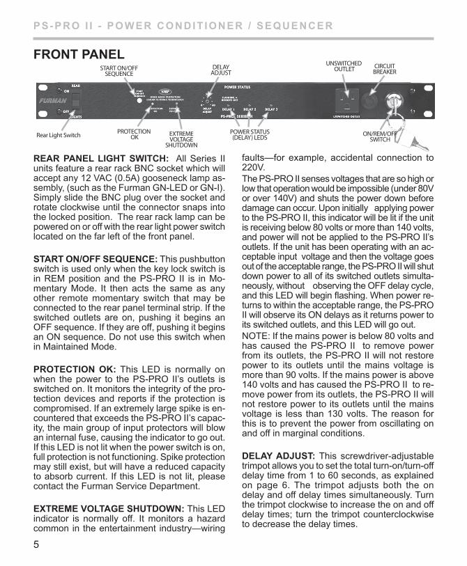
REaR PaNEl lIgHT SWITCH: All Series II units feature a rear rack BNC socket which will accept any 12 VAC (0.5A) gooseneck lamp as-sembly, (such as the Furman GN-LED or GN-I). Simply slide the BNC plug over the socket and rotate clockwise until the connector snaps into the locked position. The rear rack lamp can be powered on or off with the rear light power switch located on the far left of the front panel.
STaRT ON/OFF SEquENCE: This pushbutton switch is used only when the key lock switch is in REM position and the PS-PRO II is in Mo-mentary Mode. It then acts the same as any other remote momentary switch that may be connected to the rear panel terminal strip. If the switched outlets are on, pushing it begins an OFF sequence. If they are off, pushing it begins an ON sequence. Do not use this switch when in Maintained Mode.
PROTECTION OK: This LED is normally on when the power to the PS-PRO II’s outlets is switched on. It monitors the integrity of the pro-tection devices and reports if the protection is compromised. If an extremely large spike is en-countered that exceeds the PS-PRO II’s capac-ity, the main group of input protectors will blow an internal fuse, causing the indicator to go out. If this LED is not lit when the power switch is on, full protection is not functioning. Spike protection may still exist, but will have a reduced capacity to absorb current. If this LED is not lit, please contact the Furman Service Department.
EXTREmE VOlTagE SHuTDOWN: This LED indicator is normally off. It monitors a hazard common in the entertainment industry—wiring
faults—for example, accidental connection to 220V.The PS-PRO II senses voltages that are so high or low that operation would be impossible (under 80V or over 140V) and shuts the power down before damage can occur. Upon initially applying power to the PS-PRO II, this indicator will be lit if the unit is receiving below 80 volts or more than 140 volts, and power will not be applied to the PS-PRO II’s outlets. If the unit has been operating with an ac-ceptable input voltage and then the voltage goes out of the acceptable range, the PS-PRO II will shut down power to all of its switched outlets simulta-neously, without observing the OFF delay cycle, and this LED will begin flashing. When power re-turns to within the acceptable range, the PS-PRO II will observe its ON delays as it returns power to its switched outlets, and this LED will go out.NOTE: If the mains power is below 80 volts and has caused the PS-PRO II to remove power from its outlets, the PS-PRO II will not restore power to its outlets until the mains voltage is more than 90 volts. If the mains power is above 140 volts and has caused the PS-PRO II to re-move power from its outlets, the PS-PRO II will not restore power to its outlets until the mains voltage is less than 130 volts. The reason for this is to prevent the power from oscillating on and off in marginal conditions.
DElaY aDJuST: This screwdriver-adjustable trimpot allows you to set the total turn-on/turn-off delay time from 1 to 60 seconds, as explained on page 6. The trimpot adjusts both the on delay and off delay times simultaneously. Turn the trimpot clockwise to increase the on and off delay times; turn the trimpot counterclockwise to decrease the delay times.
FRONT PaNEl
5
PS-PRO I I - POWER CONDIT IONER / SEqu ENCER
BNC Connectorfor rear light
(models GN-I orGN-LED)
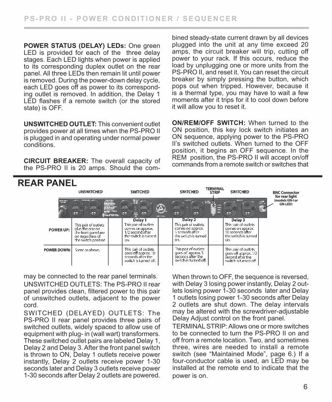
POWER STaTuS (DElaY) lEDs: One green LED is provided for each of the three delay stages. Each LED lights when power is applied to its corresponding duplex outlet on the rear panel. All three LEDs then remain lit until power is removed. During the power-down delay cycle, each LED goes off as power to its correspond-ing outlet is removed. In addition, the Delay 1 LED flashes if a remote switch (or the stored state) is OFF.
uNSWITCHED OuTlET: This convenient outlet provides power at all times when the PS-PRO II is plugged in and operating under normal power conditions.
CIRCuIT BREaKER: The overall capacity of the PS-PRO II is 20 amps. Should the com-
bined steady-state current drawn by all devices plugged into the unit at any time exceed 20 amps, the circuit breaker will trip, cutting off power to your rack. If this occurs, reduce the load by unplugging one or more units from the PS-PRO II, and reset it. you can reset the circuit breaker by simply pressing the button, which pops out when tripped. However, because it is a thermal type, you may have to wait a few moments after it trips for it to cool down before it will allow you to reset it.
ON/REm/OFF SWITCH: When turned to the ON position, this key lock switch initiates an ON sequence, applying power to the PS-PRO II’s switched outlets. When turned to the OFF position, it begins an OFF sequence. In the REM position, the PS-PRO II will accept on/off commands from a remote switch or switches that
may be connected to the rear panel terminals.UNSWITCHED OUTLETS: The PS-PRO II rear panel provides clean, filtered power to this pair of unswitched outlets, adjacent to the power cord.SWITCHED (DELAyED) OUTLETS: The PS-PRO II rear panel provides three pairs of switched outlets, widely spaced to allow use of equipment with plug- in (wall wart) transformers. These switched outlet pairs are labeled Delay 1, Delay 2 and Delay 3. After the front panel switch is thrown to ON, Delay 1 outlets receive power instantly, Delay 2 outlets receive power 1-30 seconds later and Delay 3 outlets receive power 1-30 seconds after Delay 2 outlets are powered.
When thrown to OFF, the sequence is reversed, with Delay 3 losing power instantly, Delay 2 out-lets losing power 1-30 seconds later and Delay 1 outlets losing power 1-30 seconds after Delay 2 outlets are shut down. The delay intervals may be altered with the screwdriver-adjustable Delay Adjust control on the front panel.TERMINAL STRIP: Allows one or more switches to be connected to turn the PS-PRO II on and off from a remote location. Two, and sometimes three, wires are needed to install a remote switch (see “Maintained Mode”, page 6.) If a four-conductor cable is used, an LED may be installed at the remote end to indicate that the power is on.
REaR PaNEl
6
PS-PRO I I - POWER CONDIT IONER / SEqu ENCER
MAINTAINED MODEThere are 3 maintained modes of operation:
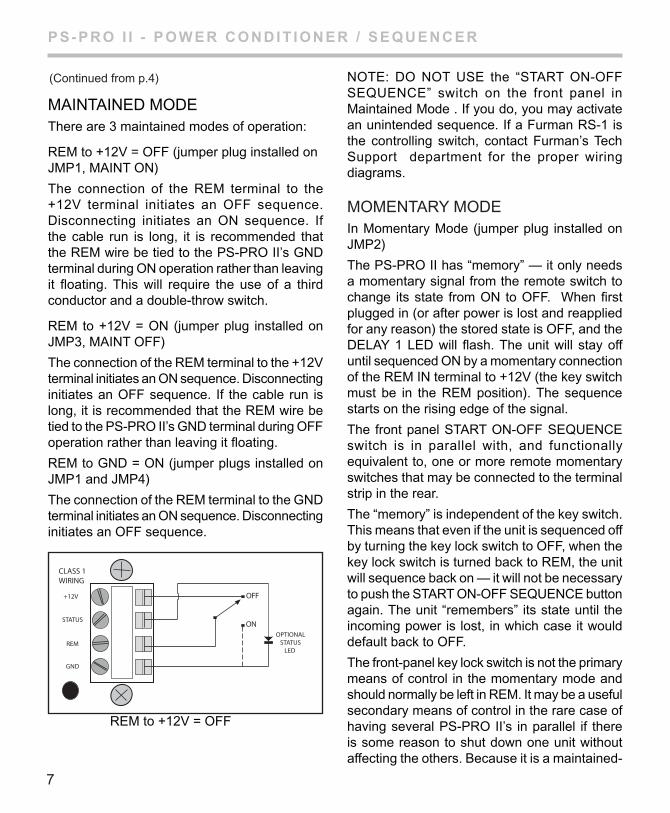
REM to +12V = OFF (jumper plug installed on JMP1, MAINT ON)
The connection of the REM terminal to the +12V terminal initiates an OFF sequence. Disconnecting initiates an ON sequence. If the cable run is long, it is recommended that the REM wire be tied to the PS-PRO II’s GND terminal during ON operation rather than leaving it floating. This will require the use of a third conductor and a double-throw switch.
REM to +12V = ON (jumper plug installed on JMP3, MAINT OFF)
The connection of the REM terminal to the +12V terminal initiates an ON sequence. Disconnecting initiates an OFF sequence. If the cable run is long, it is recommended that the REM wire be tied to the PS-PRO II’s GND terminal during OFF operation rather than leaving it floating.
REM to GND = ON (jumper plugs installed on JMP1 and JMP4)
The connection of the REM terminal to the GND terminal initiates an ON sequence. Disconnecting initiates an OFF sequence.
NOTE: DO NOT USE the “START ON-OFF SEQUENCE” switch on the front panel in Maintained Mode . If you do, you may activate an unintended sequence. If a Furman RS-1 is the controlling switch, contact Furman’s Tech Support department for the proper wiring diagrams.
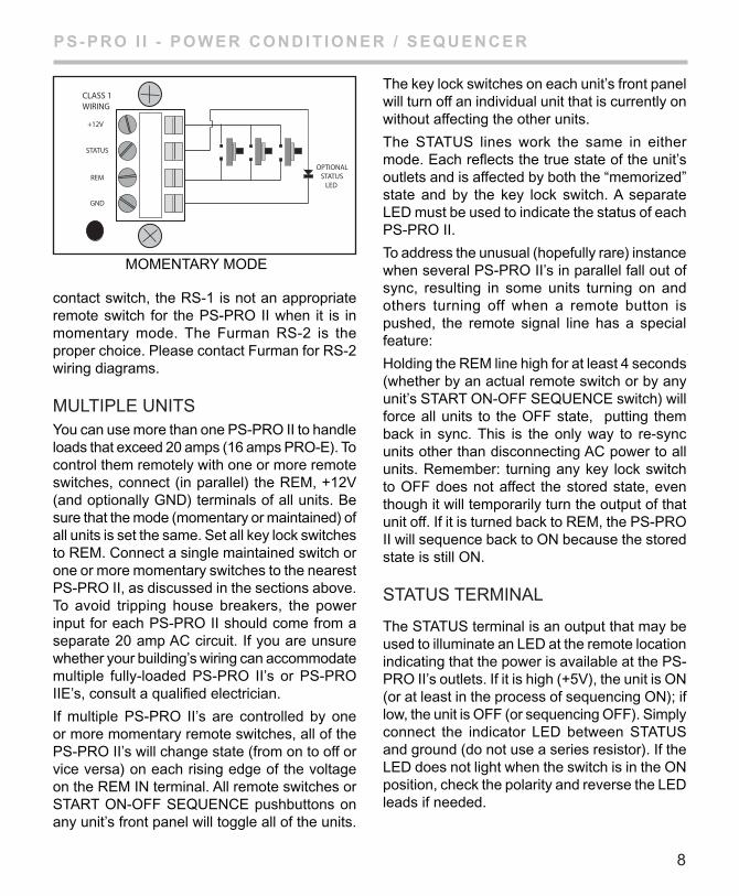
MOMENTARy MODEIn Momentary Mode (jumper plug installed on JMP2)
The PS-PRO II has “memory” — it only needs a momentary signal from the remote switch to change its state from ON to OFF. When first plugged in (or after power is lost and reapplied for any reason) the stored state is OFF, and the DELAy 1 LED will flash. The unit will stay off until sequenced ON by a momentary connection of the REM IN terminal to +12V (the key switch must be in the REM position). The sequence starts on the rising edge of the signal.
The front panel START ON-OFF SEQUENCE switch is in parallel with, and functionally equivalent to, one or more remote momentary switches that may be connected to the terminal strip in the rear.
The “memory” is independent of the key switch. This means that even if the unit is sequenced off by turning the key lock switch to OFF, when the key lock switch is turned back to REM, the unit will sequence back on — it will not be necessary to push the START ON-OFF SEQUENCE button again. The unit “remembers” its state until the incoming power is lost, in which case it would default back to OFF.
The front-panel key lock switch is not the primary means of control in the momentary mode and should normally be left in REM. It may be a useful secondary means of control in the rare case of having several PS-PRO II’s in parallel if there is some reason to shut down one unit without affecting the others. Because it is a maintained-
CLASS 1WIRING
+12V
STATUS
REM
GND
OPTIONALSTATUS
LED
OFF
ON
REM to +12V = OFF
7
(Continued from p.4)
PS-PRO I I - POWER CONDIT IONER / SEqu ENCER
contact switch, the RS-1 is not an appropriate remote switch for the PS-PRO II when it is in momentary mode. The Furman RS-2 is the proper choice. Please contact Furman for RS-2 wiring diagrams.
MULTIPLE UNITSyou can use more than one PS-PRO II to handle loads that exceed 20 amps (16 amps PRO-E). To control them remotely with one or more remote switches, connect (in parallel) the REM, +12V (and optionally GND) terminals of all units. Be sure that the mode (momentary or maintained) of all units is set the same. Set all key lock switches to REM. Connect a single maintained switch or one or more momentary switches to the nearest PS-PRO II, as discussed in the sections above. To avoid tripping house breakers, the power input for each PS-PRO II should come from a separate 20 amp AC circuit. If you are unsure whether your building’s wiring can accommodate multiple fully-loaded PS-PRO II’s or PS-PRO IIE’s, consult a qualified electrician.
If multiple PS-PRO II’s are controlled by one or more momentary remote switches, all of the PS-PRO II’s will change state (from on to off or vice versa) on each rising edge of the voltage on the REM IN terminal. All remote switches or START ON-OFF SEQUENCE pushbuttons on any unit’s front panel will toggle all of the units.
The key lock switches on each unit’s front panel will turn off an individual unit that is currently on without affecting the other units.
The STATUS lines work the same in either mode. Each reflects the true state of the unit’s outlets and is affected by both the “memorized” state and by the key lock switch. A separate LED must be used to indicate the status of each PS-PRO II.
To address the unusual (hopefully rare) instance when several PS-PRO II’s in parallel fall out of sync, resulting in some units turning on and others turning off when a remote button is pushed, the remote signal line has a special feature:
Holding the REM line high for at least 4 seconds (whether by an actual remote switch or by any unit’s START ON-OFF SEQUENCE switch) will force all units to the OFF state, putting them back in sync. This is the only way to re-sync units other than disconnecting AC power to all units. Remember: turning any key lock switch to OFF does not affect the stored state, even though it will temporarily turn the output of that unit off. If it is turned back to REM, the PS-PRO II will sequence back to ON because the stored state is still ON.
STATUS TERMINAL
The STATUS terminal is an output that may be used to illuminate an LED at the remote location indicating that the power is available at the PS-PRO II’s outlets. If it is high (+5V), the unit is ON (or at least in the process of sequencing ON); if low, the unit is OFF (or sequencing OFF). Simply connect the indicator LED between STATUS and ground (do not use a series resistor). If the LED does not light when the switch is in the ON position, check the polarity and reverse the LED leads if needed.
CLASS 1WIRING
+12V
STATUS
REM
GND
OPTIONALSTATUS
LED
MOMENTARy MODE
8

PS-PRO I I - POWER CONDIT IONER / SEqu ENCER
FLASHING DELAy 1 INDICATOR
The DELAy 1 LED on a PS-PRO II flashes to indicate that a remote switch is off or not connected. In Maintained Mode (JMP1, MAINT ON’s jumper plug is installed), this will only occur when the REM terminal is tied to the +12V terminal. In Momentary Mode, the LED flashes if the stored state is OFF. Since the flashing function is only concerned with the state of the remote switch (or switches), note that it is possible for this LED to flash even when the unit is ON. This could occur when the PS-PRO II is under local control (the key lock switch is in the ON position). In this case, DELAy 1 would flash and DELAy 2 and DELAy 3 would be steadily lit. This serves as a warning that the unit will sequence OFF if the key is turned to the REM position.
THREE YEaR
lImITED WaRRaNTY
Furman Sound, LLC., having its principal place of business at 1997 South McDowell Blvd., Petaluma, CA 94954 (“Manufacturer”) warrants its PS-PRO II Power Conditioner / Sequencer (the “Product”) as follows:
Manufacturer warrants to the original Purchaser of the Product that the Product sold hereunder will be free from defects in material and work-manship for a period of three years from the date of purchase. The Purchaser of the product is allowed fifteen days from the date of purchase to complete warranty registration by mail or on-line at the Furman website. If the Product does not conform to this Limited Warranty during the warranty period (as herein above specified), Purchaser shall notify Manufacturer in writing of the claimed defects. If the defects are of such type and nature as to be covered by this war-
ranty, Manufacturer shall authorize Purchaser to return the Product to the Furman factory or to an authorized Furman repair location. Warranty claims should be accompanied by a copy of the original purchase invoice showing the purchase date; this is not necessary if the Warranty Reg-istration was completed either via the mailed in warranty card or on-line website registration. Shipping charges to the Furman factory or to an authorized repair location must be prepaid by the Purchaser of the product. Manufacturer shall, at its own expense, furnish a replacement Product or, at Manufacturer’s option, repair the defective Product. Return shipping charges back to Purchaser will be paid by Manufacturer.
THE FOREGOING IS IN LIEU OF ALL OTHER WARRANTIES, EXPRESS OR IMPLIED, IN-CLUDING BUT NOT LIMITED TO THE IMPLIED WARRANTIES OF MERCHANTABILITy AND FITNESS FOR A PARTICULAR PURPOSE. Manufacturer does not warrant against damages or defects arising out of improper or abnormal use of handling of the Product; against defects or damages arising from improper installation, against defects in products or components not manufactured by Manufacturer, or against damages resulting from such non-Manufacturer made products or components. This warranty shall be cancelable by Manufacturer at its sole discretion if the product is modified in any way without written authorization from Furman Sound. This warranty also does not apply to Products upon which repairs have been affected or attempted by persons other than pursuant to written authorization by Manufacturer.
THIS WARRANTy IS EXCLUSIVE. The sole and exclusive obligation of Manufacturer shall be to repair or replace the defective Product in the manner and for the period provided above. Manufacturer shall not have any other obliga-tion with respect to the Products or any part thereof, whether based on contract, tort, strict
9
PS-PRO I I - POWER CONDIT IONER / SEqu ENCER
10
liability or otherwise. Under no circumstances, whether based on this Limited Warranty or otherwise, shall Manufacturer be liable for in-cidental, special, or consequential damages. Manufacturer’s employees or representatives’ ORAL OR OTHER WRITTEN STATEMENTS DO NOT CONSTITUTE WARRANTIES, shall not be relied upon by Purchaser, and are not a part of the contract for sale or this limited war-ranty. This Limited Warranty states the entire obligation of Manufacturer with respect to the Product. If any part of this Limited Warranty is determined to be void or illegal, the remainder shall remain in full force and effect.
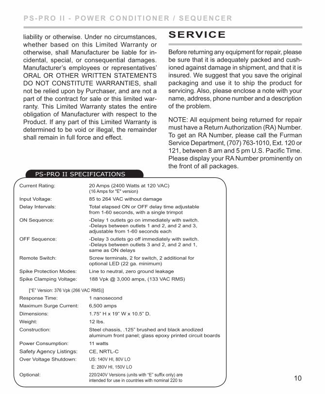
PS-PRO II SPecIfIcatIOnS
SERVICE
Before returning any equipment for repair, please be sure that it is adequately packed and cush-ioned against damage in shipment, and that it is insured. We suggest that you save the original packaging and use it to ship the product for servicing. Also, please enclose a note with your name, address, phone number and a description of the problem.
NOTE: All equipment being returned for repair must have a Return Authorization (RA) Number. To get an RA Number, please call the Furman Service Department, (707) 763-1010, Ext. 120 or 121, between 8 am and 5 pm U.S. Pacific Time. Please display your RA Number prominently on the front of all packages.
Current Rating: 20 Amps (2400 Watts at 120 VAC) (16 Amps for "E" version)
Input Voltage: 85 to 264 VAC without damage
Delay Intervals: Total elapsed ON or OFF delay time adjustable from 1-60 seconds, with a single trimpot
ON Sequence: -Delay 1 outlets go on immediately with switch. -Delays between outlets 1 and 2, and 2 and 3, adjustable from 1-60 seconds each
OFF Sequence: -Delay 3 outlets go off immediately with switch. -Delays between outlets 3 and 2, and 2 and 1, same as ON delays
Remote Switch: Screw terminals, 2 for switch, 2 additional for optional LED (22 ga. minimum)
Spike Protection Modes: Line to neutral, zero ground leakage
Spike Clamping Voltage: 188 Vpk @ 3,000 amps, (133 VAC RMS) [“E” Version: 376 Vpk (266 VAC RMS)]
Response Time: 1 nanosecond
Maximum Surge Current: 6,500 amps
Dimensions: 1.75” H x 19” W x 10.5” D.
Weight: 12 lbs.
Construction: Steel chassis, .125” brushed and black anodized aluminum front panel; glass epoxy printed circuit boards
Power Consumption: 11 watts
Safety Agency Listings: CE, NRTL-C
Over Voltage Shutdown: US: 140V HI, 80V LO
E: 280V HI, 150V LO
Optional: 220/240V Versions (units with “E” suffix only) are intended for use in countries with nominal 220 to

PS-PRO I I - POWER CONDIT IONER / SEqu ENCER
Furman Sound, LLC.1997 South McDowell Blvd.
Petaluma, California 94954-6919 USAPhone: 707-763-1010 Fax: 707-763-1310
Web: www.furmansound.com E-mail: [email protected]/2006-A