proprietary notice and liability disclaimer · landesk client manager installation ... error...
TRANSCRIPT

First Printing — May 1997
Copyright 1997 Copyright 1997NEC Computer Systems Division NEC Corporation
Packard Bell NEC, Inc. 7-1 Shiba 5-Chome, Minato-Ku1414 Massachusetts Avenue Tokyo 108-01, JapanBoxborough, MA 01719-2298 All Rights Reserved
All Rights Reserved
PROPRIETARY NOTICE AND LIABILITY DISCLAIMER
The information disclosed in this document, including all designs and relatedmaterials, is the valuable property of NEC Computer Systems Division, Packard Bell NEC,Inc. (hereinafter “NECCSD”) and/or its licensors. NECCSD and/or its licensors, as appro-priate, reserve all patent, copyright and other proprietary rights to this document, includingall design, manufacturing, reproduction, use, and sales rights thereto, except to the extentsaid rights are expressly granted to others.
The NECCSD product(s) discussed in this document are warranted in accordance with theterms of the Warranty Statement accompanying each product. However, actualperformance of each such product is dependent upon factors such as system configuration,customer data, and operator control. Since implementation by customers of each productmay vary, the suitability of specific product configurations and applications must bedetermined by the customer and is not warranted by NECCSD.
To allow for design and specification improvements, the information in this document issubject to change at any time, without notice. Reproduction of this document or portionsthereof without prior written approval of NECCSD is prohibited.
NEC is a registered trademark of NEC Corporation, and FastFacts, MagicEye, MultiSync, and PowerMateare either trademarks or registered trademarks of NEC Technologies, Inc.; these trademarks are usedunder license by Packard Bell, NEC.
All other product, brand, or trade names used in this publication are the trademarks or registeredtrademarks of their respective trademark owners.
iii
Contents
Preface.........................................................................................................................xv
Abbreviations...............................................................................................................xvii
Section 1 Technical Information
System Chassis ............................................................................................................1-3
System Board ..............................................................................................................1-4
Processor and Secondary Cache............................................................................1-7
System BIOS ........................................................................................................1-7
I/O Addressing......................................................................................................1-9
System Memory....................................................................................................1-10
Interrupt Controller...............................................................................................1-11
Plug and Play........................................................................................................1-12
ISA Bus................................................................................................................1-12
PCI Local Bus ......................................................................................................1-12
PCI/IDE Ports ......................................................................................................1-13
Parallel Interface ...................................................................................................1-13
Serial Interface......................................................................................................1-14
Infrared Interface ..................................................................................................1-15
Video Board ................................................................................................................1-15
Video Support ......................................................................................................1-15
Video Playback .....................................................................................................1-16
Audio ..........................................................................................................................1-17
SCSI Board .................................................................................................................1-18
Diskette Drive..............................................................................................................1-19
Hard Disk Drive...........................................................................................................1-19
IDE Hard Drives...................................................................................................1-19
SCSI Hard Disk ....................................................................................................1-20
Sixteen-Speed CD-ROM..............................................................................................1-20
CD-ROM Reader Operation..................................................................................1-20
CD-ROM Reader Settings.....................................................................................1-21
Power Supply ..............................................................................................................1-22
Keyboard .....................................................................................................................1-22
Mouse .........................................................................................................................1-22
Speakers ......................................................................................................................1-22
Specifications...............................................................................................................1-23
iv Contents
Section 2 Setup and Operation
Unpacking and Repacking............................................................................................2-1
System Setup ...............................................................................................................2-1
Keyboard, Mouse, and Power Cable Connection...................................................2-1
Monitor Connection..............................................................................................2-3
Speaker and Microphone Connections...................................................................2-3
Starting Up ..................................................................................................................2-7
The Setup Utility..........................................................................................................2-7
When to Use Setup ...............................................................................................2-8
How to Start Setup ...............................................................................................2-9
How to Use Setup.................................................................................................2-10
Main Menu ...........................................................................................................2-10
System Date/Time..........................................................................................2-11
Diskette Drive................................................................................................2-11
IDE Devices...................................................................................................2-11
Language .......................................................................................................2-13
Boot Options .................................................................................................2-13
Power-On COM1 Ring ..................................................................................2-16
Video Mode...................................................................................................2-16
Mouse............................................................................................................2-16
Base Memory.................................................................................................2-17
Extended Memory..........................................................................................2-17
BIOS Version ................................................................................................2-17
Advanced Menu....................................................................................................2-17
Processor Type ..............................................................................................2-18
Processor Speed.............................................................................................2-18
Cache Size .....................................................................................................2-18
Peripheral Configuration ................................................................................2-18
Advanced Chipset Configuration....................................................................2-20
Power Management Configuration .................................................................2-22
Plug and Play Configuration...........................................................................2-24
Event Logging Configuration .........................................................................2-26
Security Menu.......................................................................................................2-27
Enter Password and Set Administrative Password ..........................................2-29
Unattended Start ............................................................................................2-29
Security Hot Key (CTRL-ALT-) ....................................................................2-30
Exit Menu.............................................................................................................2-30
Contents v
Exit Saving Changes ......................................................................................2-30
Exit Discarding Changes ................................................................................2-31
Load Setup Defaults.......................................................................................2-31
Discard Changes ............................................................................................2-31
Flash Utility.................................................................................................................2-31
NECCSD Bulletin Board Service ..........................................................................2-32
Flash Utility..........................................................................................................2-34
SCSISelect Utility........................................................................................................2-35
LANDesk Client Manager............................................................................................2-35
LANDesk Client Manager Setup...........................................................................2-35
Features................................................................................................................2-35
PC Health Indicator ..............................................................................................2-35
Managing Workstations .................................................................................2-35
PC Health Meter ............................................................................................2-36
PC Health Description....................................................................................2-36
Inventory ..............................................................................................................2-37
Using DMI............................................................................................................2-37
NEC MagicEye Technology..................................................................................2-38
Video Drivers ..............................................................................................................2-38
Changing Display Properties .................................................................................2-39
Windows 95...................................................................................................2-39
Windows NT 4.0............................................................................................2-40
CD Restore..................................................................................................................2-41
Selecting CD Restore Options...............................................................................2-41
Restore Individual Files..................................................................................2-41
System Recovery ...........................................................................................2-41
Restoring Individual Files......................................................................................2-42
Selecting Files ................................................................................................2-43
Checking Selected Files..................................................................................2-43
Restoring the Files .........................................................................................2-44
Recovering the System..........................................................................................2-44
Windows NT 4.0 Application CD Installation Instructions............................................2-45
McAfee VirusScan Installation..............................................................................2-45
LANDesk Client Manager Installation...................................................................2-46
Local Mode ...................................................................................................2-46
Administrator Mode.......................................................................................2-47
Driver CD Installation Instructions...............................................................................2-48
vi Contents
Driver Installation Guidelines ................................................................................2-48
Guidelines for Windows 95 Installations.........................................................2-48
Guidelines for Windows NT Installations........................................................2-49
Driver Installation For the Windows 95 Operating System.....................................2-49
Preparation ....................................................................................................2-49
NEC 16X CD-ROM Drivers ..........................................................................2-50
PIIX3 IDE Drivers.........................................................................................2-50
Matrox Mystique Video Drivers.....................................................................2-51
Yamaha Audio Drivers...................................................................................2-52
Driver Installation for the Windows NT Operating System....................................2-53
Preparation ....................................................................................................2-53
PIIX3 IDE Drivers.........................................................................................2-53
Matrox Mystique Video Drivers.....................................................................2-54
Yamaha Audio Drivers...................................................................................2-55
Number Nine Imagine 128 Series 2 Video Drivers..........................................2-56
Section 3 Option Installation
General Rules For Installing Options............................................................................3-1
Precautions...........................................................................................................3-1
Optional Hardware................................................................................................3-2
Removing the System Unit Cover ................................................................................3-3
Removing the Cover .............................................................................................3-3
Replacing the System Unit Cover ..........................................................................3-5
Adding Internal Options...............................................................................................3-6
Expansion Boards .................................................................................................3-7
Slot Locations................................................................................................3-8
Expansion Board Installation..........................................................................3-8
Expansion Board Removal .............................................................................3-10
SIMM Upgrade.....................................................................................................3-11
Checking the Memory in the System ..............................................................3-11
SIMM Removal .............................................................................................3-13
SIMM Installation..........................................................................................3-13
Video Upgrade .....................................................................................................3-14
Data Storage Devices............................................................................................3-16
Device Support ..............................................................................................3-16
Device Slots...................................................................................................3-16
Device Preparation.........................................................................................3-18
Contents vii
Device Cables ................................................................................................3-18
Diskette Drive Signal Cable............................................................................3-19
IDE Signal Cables..........................................................................................3-20
SCSI Cable ....................................................................................................3-20
System Power Cables.....................................................................................3-21
Cabling an IDE or SCSI Device .....................................................................3-21
Cabling a Diskette Drive ................................................................................3-22
Storage Device Installation....................................................................................3-23
3 1/2-Inch Drive Installation...........................................................................3-23
Removing the Side Panel................................................................................3-26
Removing the Front Panel ..............................................................................3-27
Installing the 5 1/4-Inch Device......................................................................3-29
Replacing the Front and Side Panels...............................................................3-31
Adding External Options..............................................................................................3-31
Parallel Printer ......................................................................................................3-32
Serial Devices .......................................................................................................3-32
SCSI Devices........................................................................................................3-33
Section 4 Maintenance and Troubleshooting
Online Services ............................................................................................................4-2
NEC’s FastFacts Service.......................................................................................4-2
NECCSD Bulletin Board Service ..........................................................................4-3
E-mail/Fax Technical Support Service...................................................................4-5
Internet .................................................................................................................4-5
NECCSD Technical Support Services...................................................................4-6
Maintenance ................................................................................................................4-6
System Cleaning....................................................................................................4-6
Keyboard Cleaning................................................................................................4-7
Mouse Cleaning ....................................................................................................4-7
Troubleshooting...........................................................................................................4-8
Error Messages.....................................................................................................4-8
Diagnosing and Solving Problems .........................................................................4-11
Beep Codes...........................................................................................................4-17
CMOS Battery Replacement.................................................................................4-17
viii Contents
Section 5 Repair
Disassembly and Reassembly........................................................................................5-1
System Unit Cover Removal .................................................................................5-2
Side Panel Removal ..............................................................................................5-4
Expansion Board Removal ....................................................................................5-4
SIMM Removal ....................................................................................................5-5
Front Panel Assembly Removal .............................................................................5-7
Blank Panel and Metal Cover Plate Removal.........................................................5-7
3 1/2-Inch Diskette Drive Removal .......................................................................5-8
3 1/2-Inch Hard Disk Drive Removal ....................................................................5-10
5 1/4-Inch Device Removal...................................................................................5-11
Power Supply Removal.........................................................................................5-13
System Board Removal.........................................................................................5-15
Processor Subsystem Removal ..............................................................................5-16
Illustrated Parts Breakdown.........................................................................................5-17
Appendix A Connector Pin Assignments
I/O, Power Supply, and Chassis Intrusion Connectors ..................................................A-1
Parallel Interface Connector..................................................................................A-2
Serial Interface Connectors...................................................................................A-3
Keyboard and Mouse Connectors..........................................................................A-4
USB Connectors ...................................................................................................A-5
Audio/MIDI Connectors .......................................................................................A-5
Power Supply Connector ......................................................................................A-6
Chassis Intrusion Connector..................................................................................A-7
Storage Device Connectors..........................................................................................A-7
Diskette Drive Connector......................................................................................A-8
IDE Connectors ....................................................................................................A-9
LED Connectors..........................................................................................................A-10
Hard Drive LED Connector ..................................................................................A-10
Power LED Connector..........................................................................................A-11
Reset Button Connector........................................................................................A-11
Infrared Connector................................................................................................A-12
Sleep Connector....................................................................................................A-12
Power On Connector ............................................................................................A-13
ISA, PCI, and SIMM Connectors.................................................................................A-13
Contents ix
ISA Pin Assignments.............................................................................................A-13
PCI Pin Assignments.............................................................................................A-15
SIMM Sockets......................................................................................................A-16
Appendix B System Board Settings
Changing Jumper Settings............................................................................................B-2
System Board Jumper Locations ...........................................................................B-3
Changing System Board Jumper Settings ..............................................................B-4
Processor/Bus Speed Jumpers........................................................................B-4
BIOS Recovery..............................................................................................B-6
Clearing CMOS .............................................................................................B-7
Denying Access to CMOS Setup....................................................................B-8
Clearing the Password....................................................................................B-10
Appendix C Hard Disk Drive Specifications
Hard Disk Drive Specifications ....................................................................................C-1
Appendix D CD-ROM Reader Specifications and Jumper Settings
CD-ROM Reader Specifications...................................................................................D-1
CD-ROM Reader Connectors and Jumper Settings ......................................................D-2
List of Figures
1-1 System Controls and Storage Device Slots .....................................................1-3
1-2 Rear Panel Features........................................................................................1-4
1-3 IDE Hard Disk Drive Jumper Settings............................................................1-20
1-4 CD-ROM Reader Controls and Indicators......................................................1-21
1-5 CD-ROM Jumper Settings .............................................................................1-22
2-1 Voltage Selector Switch.................................................................................2-2
2-2 Keyboard/Mouse Connections........................................................................2-2
2-3 Monitor Signal Cable Connection...................................................................2-3
2-4 Right Speaker ................................................................................................2-4
2-5 Speaker Cables...............................................................................................2-4
2-6 Connecting the Two Speakers........................................................................2-5
2-7 Attaching the Microphone and Y-Cable..........................................................2-6
2-8 Connecting the AC Adapter ...........................................................................2-6
x Contents
2-9 Power Button.................................................................................................2-7
2-10 Main Menu ....................................................................................................2-9
2-11 Display Properties Window – Windows 95.....................................................2-39
2-12 Display Properties Window – Windows NT 4.0..............................................2-40
3-1 Cover Screws.................................................................................................3-4
3-2 Releasing the System Unit Cover....................................................................3-5
3-3 System Unit Cover Replacement....................................................................3-6
3-4 System Board Upgrade Sockets and Connectors ............................................3-7
3-5 Expansion Slot Locations...............................................................................3-8
3-6 Removing a Slot Cover ..................................................................................3-9
3-7 Inserting the Expansion Board........................................................................3-10
3-8 Removing a SIMM.........................................................................................3-13
3-9 Inserting the SIMM........................................................................................3-14
3-10 Aligning the Video Module with the Socket ...................................................3-15
3-11 Storage Device Slots......................................................................................3-17
3-12 System Board Cable Connectors ....................................................................3-19
3-13 Diskette Drive Signal Cable............................................................................3-19
3-14 IDE Cable Connectors ...................................................................................3-20
3-15 SCSI Connectors ...........................................................................................3-20
3-16 Power Cable Connectors................................................................................3-21
3-17 Connecting IDE Device Cables ......................................................................3-22
3-18 Connecting 1.2-MB Diskette Drive Cables .....................................................3-22
3-19 Locating the Power Supply ............................................................................3-24
3-20 Removing the Power Supply Screws ..............................................................3-25
3-21 Securing a 3 1/2-Inch Drive............................................................................3-26
3-22 Removing Side Panel Screws .........................................................................3-27
3-23 Removing the Front Panel ..............................................................................3-28
3-24 Removing the Slot Cover ...............................................................................3-28
3-25 Attaching the Device Rails .............................................................................3-29
3-26 Inserting the Device .......................................................................................3-30
3-27 Aligning the Front Panel.................................................................................3-31
3-28 Connecting a Printer Cable.............................................................................3-32
3-29 Connecting an RS-232C Cable .......................................................................3-33
3-30 Connecting a SCSI Cable ...............................................................................3-34
Contents xi
4-1 Removing the Mouse Ball Cover....................................................................4-8
4-2 Battery Socket Location.................................................................................4-18
4-3 Battery Removal ............................................................................................4-18
5-1 Cover Screws.................................................................................................5-3
5-2 Releasing the System Unit Cover....................................................................5-3
5-3 Removing Side Panel Screws .........................................................................5-4
5-4 Expansion Board Removal .............................................................................5-5
5-5 System Board SIMM Sockets ........................................................................5-6
5-6 Removing a SIMM.........................................................................................5-6
5-7 Removing the Front Panel ..............................................................................5-7
5-8 Removing the Slot Cover ...............................................................................5-8
5-9 3 1/2-Inch Diskette Drive Cables....................................................................5-8
5-10 Diskette Drive Screws....................................................................................5-9
5-11 Diskette Drive Removal .................................................................................5-9
5-12 3 1/2-Inch Hard Disk Drive Cables.................................................................5-10
5-13 Removing the 3 1/2-Inch Drive ......................................................................5-11
5-14 Removing the Device .....................................................................................5-12
5-15 Removing the Device Rails.............................................................................5-12
5-16 Power Supply Screws ....................................................................................5-13
5-17 Power Supply Ducting (266-MHz Models) ....................................................5-14
5-18 System Board Removal..................................................................................5-15
5-19 Processor Subsystem Removal .......................................................................5-16
5-20 PowerMate Professional Series Illustrated Parts Breakdown ..........................5-20
A-1 System Board Chassis Intrusion, Power, and I/O Connector Locations...........A-2
A-2 Parallel Interface Connector...........................................................................A-2
A-3 Serial Interface Connector..............................................................................A-3
A-4 PS/2-Style Keyboard and Mouse Interface Connectors...................................A-4
A-5 Storage Device Connector Locations .............................................................A-7
A-6 LED Connectors ............................................................................................A-10
A-7 Hard Disk LED Connector.............................................................................A-10
A-8 Power LED Connector...................................................................................A-11
A-9 Reset Button Connector.................................................................................A-11
A-10 Infrared Connector.........................................................................................A-12
xii Contents
A-11 Sleep Connector.............................................................................................A-12
A-12 Power On Connector .....................................................................................A-13
A-13 PCI, ISA, and SIMM Connector Locations ....................................................A-13
B-1 Locating System Configuration Jumpers.........................................................B-3
List of Tables
1-1 PowerMate Professional Series System Configurations...................................1-1
1-2 System Board Feature Components................................................................1-6
1-3 System Memory Map.....................................................................................1-8
1-4 I/O Address Map ...........................................................................................1-9
1-5 Interrupt Level Assignments...........................................................................1-11
1-6 Parallel Port Addressing and Interrupts ..........................................................1-13
1-7 Serial Port Addressing and Interrupts .............................................................1-14
1-8 Matrox Mystique Video Board Support .........................................................1-16
1-9 Number Nine Imagine Video Board Support ..................................................1-16
1-10 Audio Subsystem Resources..........................................................................1-18
1-11 Specifications.................................................................................................1-23
2-1 Navigation Keys.............................................................................................2-10
2-2 Hot Key Parameters .......................................................................................2-24
2-3 Security Passwords ........................................................................................2-28
3-1 Recommended Memory Upgrade Path ...........................................................3-12
4-1 NECCSD Service and Information Telephone Numbers .................................4-1
4-2 System Error Messages..................................................................................4-9
4-3 PCI Error Messages.......................................................................................4-10
4-4 Problems and Solutions..................................................................................4-12
4-5 Diagnostic Beep Codes ..................................................................................4-17
5-1 PowerMate Professional Series System Unit Disassembly Sequence ...............5-1
5-2 PowerMate Professional Series Field-Replaceable Parts List...........................5-15
5-3 PowerMate Professional Series Options .........................................................5-19
5-4 PowerMate Professional Series Documentation and Packaging.......................5-19
Contents xiii
A-1 System Board Connectors ..............................................................................A-1
A-2 Parallel Interface Pin Assignments..................................................................A-3
A-3 Serial Interface Pin Assignments.....................................................................A-4
A-4 Keyboard and Mouse Pin Assignments...........................................................A-4
A-5 USB Port Pin Assignments.............................................................................A-5
A-6 Microphone In Pin Assignments .....................................................................A-5
A-7 Line In Pin Assignments.................................................................................A-5
A-8 Line Out Pin Assignments ..............................................................................A-5
A-9 MIDI Pin Assignments ...................................................................................A-6
A-10 Power Connector Pin Assignments.................................................................A-6
A-11 Chassis Intrusion Pin Assignments..................................................................A-7
A-12 Diskette Drive Pin Assignments......................................................................A-8
A-13 IDE Interface Pin Assignments.......................................................................A-9
A-14 Hard Disk LED Pin Assignments....................................................................A-10
A-15 Power LED Pin Assignments .........................................................................A-11
A-16 Reset Pin Assignments ...................................................................................A-11
A-17 Infrared Pin Assignments................................................................................A-12
A-18 Sleep Pin Assignments ...................................................................................A-12
A-19 Power On Pin Assignments ............................................................................A-13
A-20 ISA Bus Pin Assignments...............................................................................A-14
A-21 PCI Connector Pin Assignments.....................................................................A-15
A-22 SIMM Socket Pin Assignments......................................................................A-16
B-1 System Board Jumper Settings .......................................................................B-4
C-1 Quantum 3.2-GB Hard Disk Specifications ....................................................C-1
C-2 4-GB Seagate Hard Disk Specifications..........................................................C-3
D-1 Specifications for Sixteen-Speed NEC CD-ROM Reader................................D-1
D-2 Jumper A Settings..........................................................................................D-3
D-3 Jumper B Settings ..........................................................................................D-4

xiv Contents
xv
Preface
This service and reference manual for NEC PowerMate® Professional Series computersystems contains hardware and interface information for users who need an overview ofsystem design. The manual also includes system setup information, procedures for installingoptions, and illustrated parts lists. The manual is written for NEC-trained customerengineers, system analysts, service center personnel, and dealers.
The manual is organized as follows:
Section 1 — Technical Information, provides an overview of the system features,hardware design, interface ports, and internal devices. System specifications are listed,including dimensions, weight, environment, safety compliance, power consumption, andmemory.
Section 2 — Setup and Operation, includes unpacking, setup, and operation information.It contains procedures for configuring the system through the Setup utility program andreinstalling the system software. This section includes procedures for restoring theoperating system, various drivers, and application programs. Information on using the BIOSUpdate utility is also included.
Section 3 — Option Installation, provides installation procedures for adding optionalexpansion boards, diskette and hard disk storage devices, and system and video memory.
Section 4 — Maintenance and Troubleshooting, provides information on cleaning thesystem and identifying system malfunctions.
Section 5 — Repair, includes disassembly procedures along with an exploded viewdiagram of the system. Also included are parts lists for field-replaceable parts.
Appendix A — Connector Pin Assignments, provides a list of the system board’s internaland external connector pin assignments.
Appendix B — System Board Settings, includes information on setting jumpers forclearing passwords, resetting CMOS, disabling Setup access, and recovering from acorrupted BIOS.
Appendix C — Hard Disk Specifications, includes specifications for the IDE and SCSIhard disk drives provided with the computer.
Appendix D — CD-ROM Reader Specifications and Jumper Settings, providesspecification and jumper setting information for the CD-ROM reader provided with thecomputer.
An Index is provided at the end of this guide.
xvii
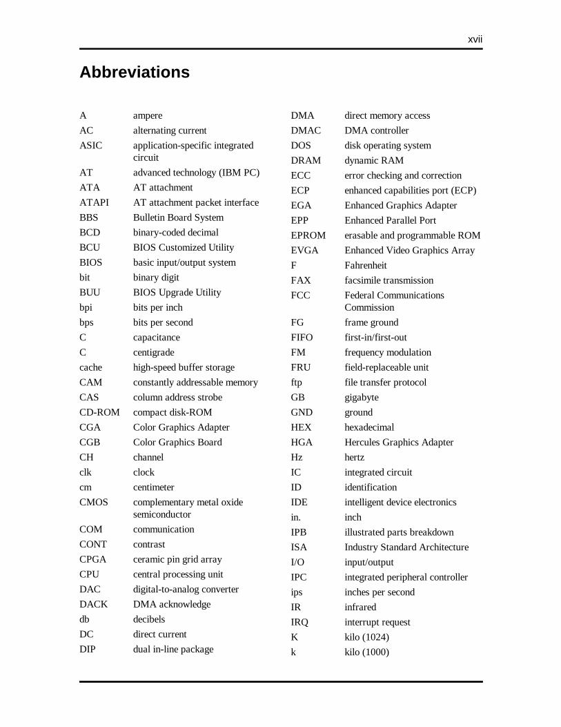
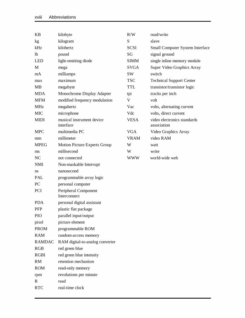
Abbreviations
A ampere
AC alternating current
ASIC application-specific integratedcircuit
AT advanced technology (IBM PC)
ATA AT attachment
ATAPI AT attachment packet interface
BBS Bulletin Board System
BCD binary-coded decimal
BCU BIOS Customized Utility
BIOS basic input/output system
bit binary digit
BUU BIOS Upgrade Utility
bpi bits per inch
bps bits per second
C capacitance
C centigrade
cache high-speed buffer storage
CAM constantly addressable memory
CAS column address strobe
CD-ROM compact disk-ROM
CGA Color Graphics Adapter
CGB Color Graphics Board
CH channel
clk clock
cm centimeter
CMOS complementary metal oxidesemiconductor
COM communication
CONT contrast
CPGA ceramic pin grid array
CPU central processing unit
DAC digital-to-analog converter
DACK DMA acknowledge
db decibels
DC direct current
DIP dual in-line package
DMA direct memory access
DMAC DMA controller
DOS disk operating system
DRAM dynamic RAM
ECC error checking and correction
ECP enhanced capabilities port (ECP)
EGA Enhanced Graphics Adapter
EPP Enhanced Parallel Port
EPROM erasable and programmable ROM
EVGA Enhanced Video Graphics Array
F Fahrenheit
FAX facsimile transmission
FCC Federal Communications Commission
FG frame ground
FIFO first-in/first-out
FM frequency modulation
FRU field-replaceable unit
ftp file transfer protocol
GB gigabyte
GND ground
HEX hexadecimal
HGA Hercules Graphics Adapter
Hz hertz
IC integrated circuit
ID identification
IDE intelligent device electronics
in. inch
IPB illustrated parts breakdown
ISA Industry Standard Architecture
I/O input/output
IPC integrated peripheral controller
ips inches per second
IR infrared
IRQ interrupt request
K kilo (1024)
k kilo (1000)
xviii Abbreviations
KB kilobyte
kg kilogram
kHz kilohertz
lb pound
LED light-emitting diode
M mega
mA milliamps
max maximum
MB megabyte
MDA Monochrome Display Adapter
MFM modified frequency modulation
MHz megahertz
MIC microphone
MIDI musical instrument device interface
MPC multimedia PC
mm millimeter
MPEG Motion Picture Experts Group
ms millisecond
NC not connected
NMI Non-maskable Interrupt
ns nanosecond
PAL programmable array logic
PC personal computer
PCI Peripheral Component Interconnect
PDA personal digital assistant
PFP plastic flat package
PIO parallel input/output
pixel picture element
PROM programmable ROM
RAM random-access memory
RAMDAC RAM digital-to-analog converter
RGB red green blue
RGBI red green blue intensity
RM retention mechanism
ROM read-only memory
rpm revolutions per minute
R read
RTC real-time clock
R/W read/write
S slave
SCSI Small Computer System Interface
SG signal ground
SIMM single inline memory module
SVGA Super Video Graphics Array
SW switch
TSC Technical Support Center
TTL transistor/transistor logic
tpi tracks per inch
V volt
Vac volts, alternating current
Vdc volts, direct current
VESA video electronics standardsassociation
VGA Video Graphics Array
VRAM video RAM
W watt
W write
WWW world-wide web
Section 1
Technical Information
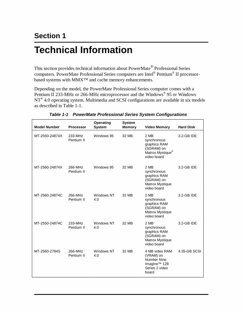
This section provides technical information about PowerMate® Professional Seriescomputers. PowerMate Professional Series computers are Intel® Pentium® II processor-based systems with MMX™ and cache memory enhancements.
Depending on the model, the PowerMate Professional Series computer comes with aPentium II 233-MHz or 266-MHz microprocessor and the Windows® 95 or WindowsNT® 4.0 operating system. Multimedia and SCSI configurations are available in six modelsas described in Table 1-1.
Table 1-1 PowerMate Professional Series System Configurations
Model Number
Processor
OperatingSystem
SystemMemory
Video Memory
Hard Disk
MT-2550-24874X 233-MHzPentium II
Windows 95 32 MB 2 MBsynchronousgraphics RAM(SGRAM) onMatrox Mystique®
video board
3.2-GB IDE
MT-2560-24874X 266-MHzPentium II
Windows 95 32 MB 2 MBsynchronousgraphics RAM(SGRAM) onMatrox Mystiquevideo board
3.2-GB IDE
MT-2560-24874C 266-MHzPentium II
Windows NT4.0
32 MB 2 MBsynchronousgraphics RAM(SGRAM) onMatrox Mystiquevideo board
3.2-GB IDE
MT-2550-24874C 233-MHzPentium II
Windows NT4.0
32 MB 2 MBsynchronousgraphics RAM(SGRAM) onMatrox Mystiquevideo board
3.2-GB IDE
MT-2560-2784S 266-MHzPentium II
Windows NT4.0
32 MB 4 MB video RAM(VRAM) onNumber NineImagine™ 128Series 2 videoboard
4.35-GB SCSI
1-2 Technical Information
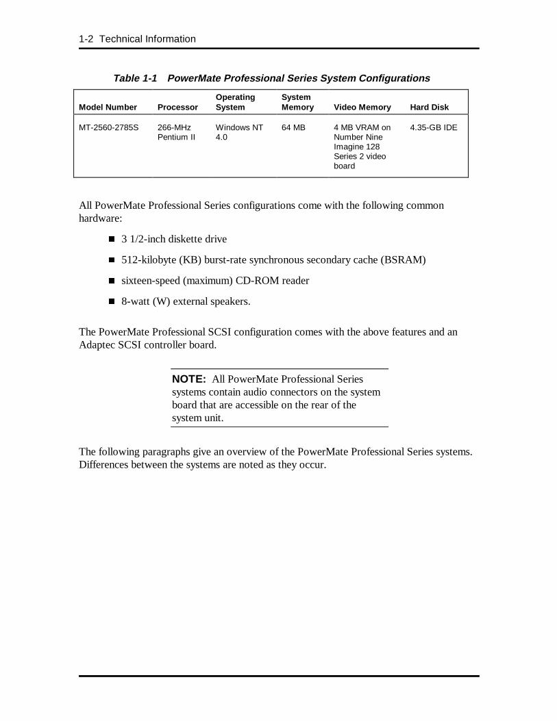
Table 1-1 PowerMate Professional Series System Configurations
Model Number
Processor
OperatingSystem
SystemMemory
Video Memory
Hard Disk
MT-2560-2785S 266-MHzPentium II
Windows NT4.0
64 MB 4 MB VRAM onNumber NineImagine 128Series 2 videoboard
4.35-GB IDE
All PowerMate Professional Series configurations come with the following commonhardware:
� 3 1/2-inch diskette drive
� 512-kilobyte (KB) burst-rate synchronous secondary cache (BSRAM)
� sixteen-speed (maximum) CD-ROM reader
� 8-watt (W) external speakers.
The PowerMate Professional SCSI configuration comes with the above features and anAdaptec SCSI controller board.
NOTE: All PowerMate Professional Seriessystems contain audio connectors on the systemboard that are accessible on the rear of thesystem unit.
The following paragraphs give an overview of the PowerMate Professional Series systems.Differences between the systems are noted as they occur.
Technical Information 1-3
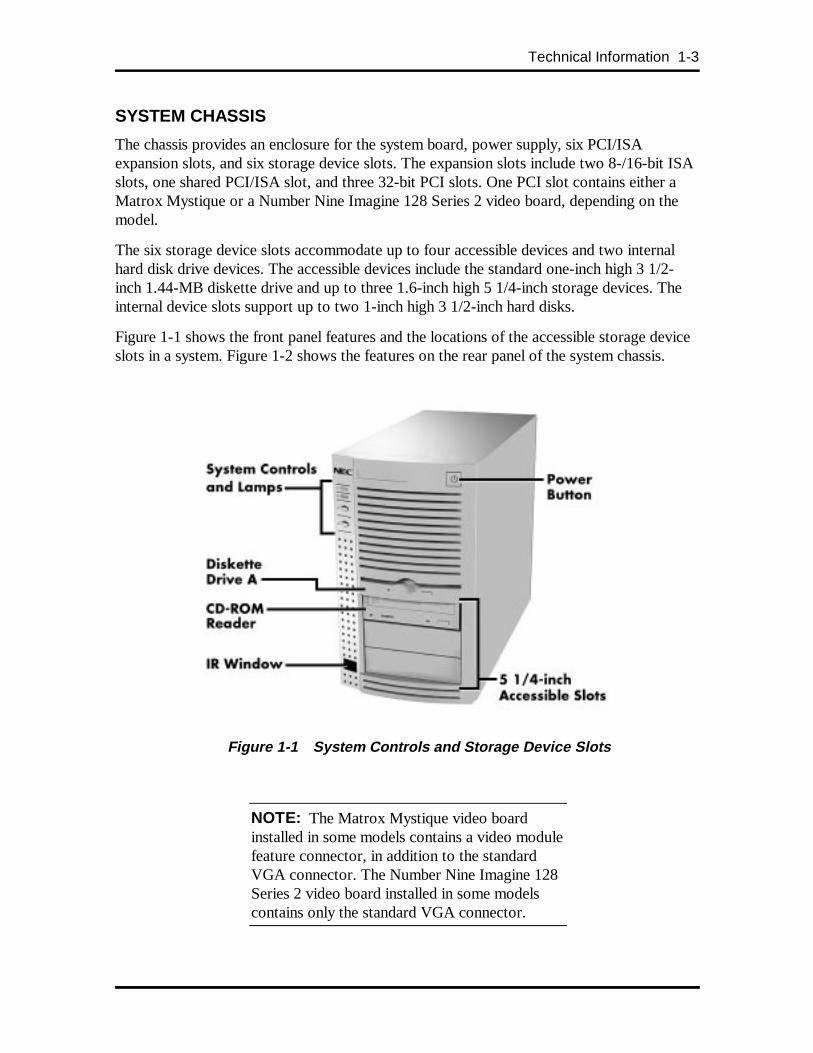
SYSTEM CHASSIS
The chassis provides an enclosure for the system board, power supply, six PCI/ISAexpansion slots, and six storage device slots. The expansion slots include two 8-/16-bit ISAslots, one shared PCI/ISA slot, and three 32-bit PCI slots. One PCI slot contains either aMatrox Mystique or a Number Nine Imagine 128 Series 2 video board, depending on themodel.
The six storage device slots accommodate up to four accessible devices and two internalhard disk drive devices. The accessible devices include the standard one-inch high 3 1/2-inch 1.44-MB diskette drive and up to three 1.6-inch high 5 1/4-inch storage devices. Theinternal device slots support up to two 1-inch high 3 1/2-inch hard disks.
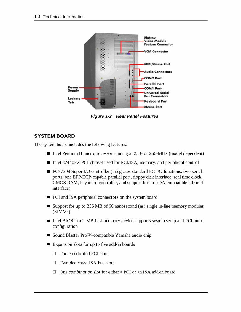
Figure 1-1 shows the front panel features and the locations of the accessible storage deviceslots in a system. Figure 1-2 shows the features on the rear panel of the system chassis.
Figure 1-1 System Controls and Storage Device Slots
NOTE: The Matrox Mystique video boardinstalled in some models contains a video modulefeature connector, in addition to the standardVGA connector. The Number Nine Imagine 128Series 2 video board installed in some modelscontains only the standard VGA connector.
1-4 Technical Information
Figure 1-2 Rear Panel Features
SYSTEM BOARD
The system board includes the following features:
� Intel Pentium II microprocessor running at 233- or 266-MHz (model dependent)
� Intel 82440FX PCI chipset used for PCI/ISA, memory, and peripheral control
� PC87308 Super I/O controller (integrates standard PC I/O functions: two serialports, one EPP/ECP-capable parallel port, floppy disk interface, real time clock,CMOS RAM, keyboard controller, and support for an IrDA-compatible infraredinterface)
� PCI and ISA peripheral connectors on the system board
� Support for up to 256 MB of 60 nanosecond (ns) single in-line memory modules(SIMMs)
� Intel BIOS in a 2-MB flash memory device supports system setup and PCI auto-configuration
� Sound Blaster Pro™-compatible Yamaha audio chip
� Expansion slots for up to five add-in boards
Three dedicated PCI slots
Two dedicated ISA-bus slots
One combination slot for either a PCI or an ISA add-in board

Technical Information 1-5
NOTE: One expansion slot contains either aMatrox Mystique or a Number Nine Imagine 128Series 2 video board as standard equipment. InSCSI models, a SCSI adapter board is alsoinstalled.
� 200-watt power supply (switch-selectable for 115 and 230 Vac operation)
� Two RS-232C-compatible 9-pin serial connectors
� One multimode, 25-pin Centronics®-compatible parallel port
� Two Universal Serial Bus (USB) connectors
� Six device slots:
One 1-inch high 3 1/2-inch slot (contains standard 1.44-MB diskette drive)
Three 1.6-inch high 5 1/4-inch slots (one slot contains the standard CD-ROMreader
Two internal 1-inch high 3 1/2-inch slots (one slot contains the standard harddisk)
� PS/2®-style keyboard and mouse connector
� Speaker mounted on the system board
� Password protection and padlock slot for system security
� Hardware management ASIC (NEC MagicEye™) chip mounted on the systemboard (see Section 2).
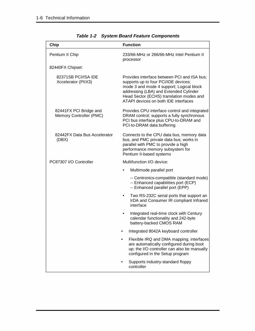
Table 1-2 lists the major chips on the system board. See Appendix A, “Connector PinAssignments,” for a list of the system board connectors. See Appendix B, “System BoardSettings,” for a description of system board switches.
1-6 Technical Information
Table 1-2 System Board Feature Components
Chip Function
Pentium II Chip 233/66-MHz or 266/66-MHz Intel Pentium IIprocessor
82440FX Chipset:
82371SB PCI/ISA IDEXccelerator (PIIX3)
82441FX PCI Bridge andMemory Controller (PMC)
82442FX Data Bus Accelerator (DBX)
Provides interface between PCI and ISA bus;supports up to four PCI/IDE devices;mode 3 and mode 4 support; Logical blockaddressing (LBA) and Extended CylinderHead Sector (ECHS) translation modes andATAPI devices on both IDE interfaces
Provides CPU interface control and integratedDRAM control; supports a fully synchronousPCI bus interface plus CPU-to-DRAM andPCI-to-DRAM data buffering
Connects to the CPU data bus, memory databus, and PMC private data bus; works inparallel with PMC to provide a highperformance memory subsystem forPentium II-based systems
PC87307 I/O Controller Multifunction I/O device:
• Multimode parallel port
-- Centronics-compatible (standard mode)-- Enhanced capabilities port (ECP)-- Enhanced parallel port (EPP)
• Two RS-232C serial ports that support anIrDA and Consumer IR compliant Infraredinterface
• Integrated real-time clock with Centurycalendar functionality and 242-bytebattery-backed CMOS RAM
• Integrated 8042A keyboard controller
• Flexible IRQ and DMA mapping; interfacesare automatically configured during bootup; the I/O controller can also be manuallyconfigured in the Setup program
• Supports industry-standard floppycontroller
Technical Information 1-7
Processor and Secondary Cache
The PowerMate Professional uses a Pentium II processor with an internal clock speed of233 MHz or 266 MHz. The external speed of the 233-MHz and 266-MHz processors is66 MHz.
Each processor has 32 KB of write-back primary cache and a math coprocessor. The32-KB primary cache provides 16 KB for instructions and 16 KB for data.
The processor is an advanced pipelined 32-bit addressing, 64-bit data processor designed tooptimize multitasking operating systems. The 64-bit registers and data paths support 64-bitaddresses and data types.
To use the Pentium II processor’s power, the system features an optimized 64-bit memoryinterface and 512 KB of secondary write-back cache incorporated into the processor.
The processor is compatible with 8-, 16-, and 32-bit software written for the Intel386™,Intel486™, Pentium, and Pentium Pro processors. The Pentium II processor is contained ona Single Edge Contact (S.E.C.) cartridge that plugs into the system board at Slot 1, which isa 242-pin edge connector. The processor subsystem consists of the following components:
� processor card (including the processor and secondary cache)
� thermal plate
� back cover.
When the processor subsystem is mounted in Slot 1, it is secured by a retention mechanism(RM) attached to the system board. The RM acts as an insertion guide and preventsmovement of the processor after installation. The processor heatsink is also stabilized bysupports that attach to the motherboard.
System BIOS
The system BIOS is from Intel/American Megatrends Incorporated (AMI) and providesISA and PCI compatibility. The BIOS is contained in a 2-MB flash memory device on thesystem board. The BIOS provides the Power-On Self Test (POST), the system Setupprogram, a PCI and IDE auto-configuration utility, and BIOS recovery code.
The system BIOS is always shadowed. Shadowing allows any BIOS routine to be executedfrom fast 32-bit onboard DRAM instead of from the slower 8-bit flash device.
NEC’s Flash ROM allows fast, economical BIOS upgrades. NEC Flash ROMs arereprogrammable system and video EPROMs. With NEC’s Flash ROM, a ROM BIOSchange is expedited in the following ways:
� is fast and easily done using a Flash utility
� eliminates the expensive replacement of ROM BIOS chips, and reduces systemmaintenance costs
1-8 Technical Information
� reduces inadvertent system board damage that can take place when replacingROMs
� facilitates adopting new technology while maintaining corporate standards
� gives network administrators company-wide control of BIOS revisions.
The BIOS programs execute the Power-On Self-Test, initialize processor controllers, andinteract with the display, diskette drives, hard disks, communication devices, andperipherals. The system BIOS also contains the Setup utility. The hardware setup defaultcopies the ROM BIOS into RAM (shadowing) for maximum performance.
The Flash ROM allows the system and video BIOS to be upgraded with the BIOS Updateutility, without removing the ROM (see Section 2 for further information on the BIOSUpdate utility). The Flash ROM supports the reprogramming of the system BIOS and thevideo BIOS.
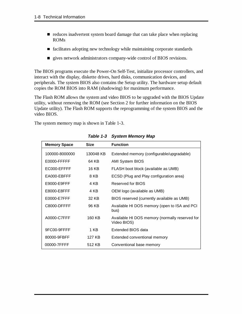
The system memory map is shown in Table 1-3.
Table 1-3 System Memory Map
Memory Space Size Function
100000-8000000 130048 KB Extended memory (configurable/upgradable)
E0000-FFFFF 64 KB AMI System BIOS
EC000-EFFFF 16 KB FLASH boot block (available as UMB)
EA000-EBFFF 8 KB ECSD (Plug and Play configuration area)
E9000-E9FFF 4 KB Reserved for BIOS
E8000-E8FFF 4 KB OEM logo (available as UMB)
E0000-E7FFF 32 KB BIOS reserved (currently available as UMB)
C8000-DFFFF 96 KB Available HI DOS memory (open to ISA and PCIbus)
A0000-C7FFF 160 KB Available HI DOS memory (normally reserved forVideo BIOS)
9FC00-9FFFF 1 KB Extended BIOS data
80000-9FBFF 127 KB Extended conventional memory
00000-7FFFF 512 KB Conventional base memory
Technical Information 1-9
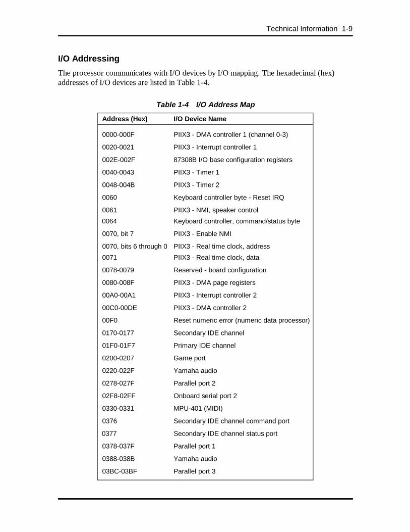
I/O Addressing
The processor communicates with I/O devices by I/O mapping. The hexadecimal (hex)addresses of I/O devices are listed in Table 1-4.
Table 1-4 I/O Address Map
Address (Hex) I/O Device Name
0000-000F PIIX3 - DMA controller 1 (channel 0-3)
0020-0021 PIIX3 - Interrupt controller 1
002E-002F 87308B I/O base configuration registers
0040-0043 PIIX3 - Timer 1
0048-004B PIIX3 - Timer 2
0060 Keyboard controller byte - Reset IRQ
0061 PIIX3 - NMI, speaker control
0064 Keyboard controller, command/status byte
0070, bit 7 PIIX3 - Enable NMI
0070, bits 6 through 0 PIIX3 - Real time clock, address
0071 PIIX3 - Real time clock, data
0078-0079 Reserved - board configuration
0080-008F PIIX3 - DMA page registers
00A0-00A1 PIIX3 - Interrupt controller 2
00C0-00DE PIIX3 - DMA controller 2
00F0 Reset numeric error (numeric data processor)
0170-0177 Secondary IDE channel
01F0-01F7 Primary IDE channel
0200-0207 Game port
0220-022F Yamaha audio
0278-027F Parallel port 2
02F8-02FF Onboard serial port 2
0330-0331 MPU-401 (MIDI)
0376 Secondary IDE channel command port
0377 Secondary IDE channel status port
0378-037F Parallel port 1
0388-038B Yamaha audio
03BC-03BF Parallel port 3
1-10 Technical Information
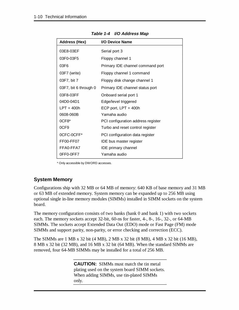
Table 1-4 I/O Address Map
Address (Hex) I/O Device Name
03E8-03EF Serial port 3
03F0-03F5 Floppy channel 1
03F6 Primary IDE channel command port
03F7 (write) Floppy channel 1 command
03F7, bit 7 Floppy disk change channel 1
03F7, bit 6 through 0 Primary IDE channel status port
03F8-03FF Onboard serial port 1
04D0-04D1 Edge/level triggered
LPT + 400h ECP port, LPT + 400h
0608-060B Yamaha audio
0CF8* PCI configuration address register
0CF9 Turbo and reset control register
0CFC-0CFF* PCI configuration data register
FF00-FF07 IDE bus master register
FFA0-FFA7 IDE primary channel
0FF0-0FF7 Yamaha audio
* Only accessible by DWORD accesses.
System Memory
Configurations ship with 32 MB or 64 MB of memory: 640 KB of base memory and 31 MBor 63 MB of extended memory. System memory can be expanded up to 256 MB usingoptional single in-line memory modules (SIMMs) installed in SIMM sockets on the systemboard.
The memory configuration consists of two banks (bank 0 and bank 1) with two socketseach. The memory sockets accept 32-bit, 60-ns for faster, 4-, 8-, 16-, 32-, or 64-MBSIMMs. The sockets accept Extended Data Out (EDO) mode or Fast Page (FM) modeSIMMs and support parity, non-parity, or error checking and correction (ECC).
The SIMMs are 1 MB x 32 bit (4 MB), 2 MB x 32 bit (8 MB), 4 MB x 32 bit (16 MB),8 MB x 32 bit (32 MB), and 16 MB x 32 bit (64 MB). When the standard SIMMs areremoved, four 64-MB SIMMs may be installed for a total of 256 MB.
CAUTION: SIMMs must match the tin metalplating used on the system board SIMM sockets.When adding SIMMs, use tin-plated SIMMsonly.
Technical Information 1-11
SIMMs install directly in the four sockets on the system board. The four sockets areassigned as Bank 0 (2 sockets) and Bank 1 (2 sockets). All configurations have two SIMMsinstalled in Bank 1.
SIMMs must be installed in pairs of the same memory type and size. Both sockets must bepopulated within a bank for the system to work. No switch or jumper settings are requiredwhen the memory is changed. The system BIOS automatically detects the SIMMs. See“Checking the Memory in the System” in Section 3 for the valid configurations.
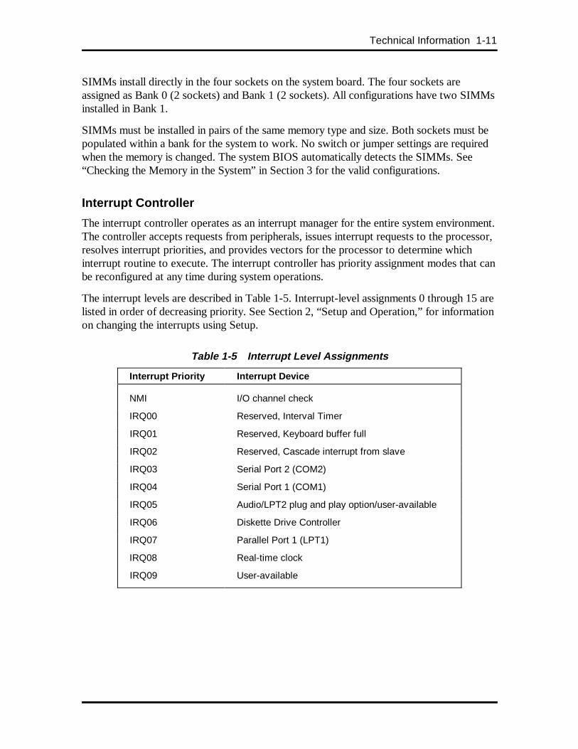
Interrupt Controller
The interrupt controller operates as an interrupt manager for the entire system environment.The controller accepts requests from peripherals, issues interrupt requests to the processor,resolves interrupt priorities, and provides vectors for the processor to determine whichinterrupt routine to execute. The interrupt controller has priority assignment modes that canbe reconfigured at any time during system operations.
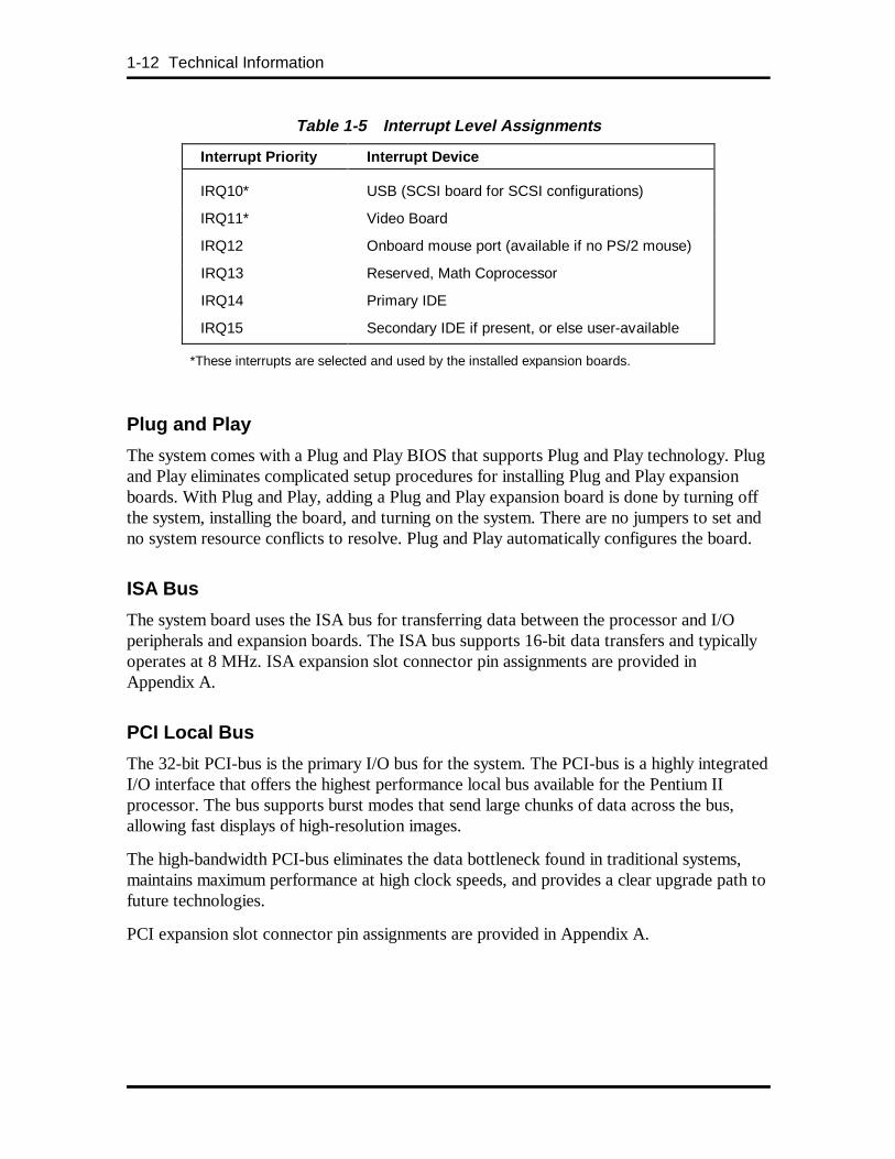
The interrupt levels are described in Table 1-5. Interrupt-level assignments 0 through 15 arelisted in order of decreasing priority. See Section 2, “Setup and Operation,” for informationon changing the interrupts using Setup.
Table 1-5 Interrupt Level Assignments
Interrupt Priority Interrupt Device
NMI I/O channel check
IRQ00 Reserved, Interval Timer
IRQ01 Reserved, Keyboard buffer full
IRQ02 Reserved, Cascade interrupt from slave
IRQ03 Serial Port 2 (COM2)
IRQ04 Serial Port 1 (COM1)
IRQ05 Audio/LPT2 plug and play option/user-available
IRQ06 Diskette Drive Controller
IRQ07 Parallel Port 1 (LPT1)
IRQ08 Real-time clock
IRQ09 User-available
1-12 Technical Information
Table 1-5 Interrupt Level Assignments
Interrupt Priority Interrupt Device
IRQ10* USB (SCSI board for SCSI configurations)
IRQ11* Video Board
IRQ12 Onboard mouse port (available if no PS/2 mouse)
IRQ13 Reserved, Math Coprocessor
IRQ14 Primary IDE
IRQ15 Secondary IDE if present, or else user-available
*These interrupts are selected and used by the installed expansion boards.
Plug and Play
The system comes with a Plug and Play BIOS that supports Plug and Play technology. Plugand Play eliminates complicated setup procedures for installing Plug and Play expansionboards. With Plug and Play, adding a Plug and Play expansion board is done by turning offthe system, installing the board, and turning on the system. There are no jumpers to set andno system resource conflicts to resolve. Plug and Play automatically configures the board.
ISA Bus
The system board uses the ISA bus for transferring data between the processor and I/Operipherals and expansion boards. The ISA bus supports 16-bit data transfers and typicallyoperates at 8 MHz. ISA expansion slot connector pin assignments are provided inAppendix A.
PCI Local Bus
The 32-bit PCI-bus is the primary I/O bus for the system. The PCI-bus is a highly integratedI/O interface that offers the highest performance local bus available for the Pentium IIprocessor. The bus supports burst modes that send large chunks of data across the bus,allowing fast displays of high-resolution images.
The high-bandwidth PCI-bus eliminates the data bottleneck found in traditional systems,maintains maximum performance at high clock speeds, and provides a clear upgrade path tofuture technologies.
PCI expansion slot connector pin assignments are provided in Appendix A.
Technical Information 1-13
PCI/IDE Ports
The system board provides two high-performance PCI/IDE ports: a primary channel and asecondary channel. Each port supports up to two devices for a total of four IDE devices.The primary PCI/IDE port has an enhanced IDE interface that supports PIO Mode 4devices with 16 MB per second 32-bit wide data transfers on the high-performance PCIlocal bus. The installed hard disk drive is connected to the primary PCI/IDE port. Inmultimedia configurations, the installed CD-ROM reader is connected to the secondaryPCI/IDE port.
Parallel Interface
The system has a 25-pin parallel bidirectional enhanced parallel port on the system board.Port specifications conform to the IBM-PC standards. The port supports EnhancedCapabilities Port (ECP) and Enhanced Parallel Port (EPP) modes for devices that requireECP or EPP protocols. The protocols allow high-speed bidirectional transfer over a parallelport. This increases parallel port functionality by supporting more devices.
The BIOS has automatic ISA printer port sensing. If the BIOS detects an ISA printer portmapped to the same address, the built-in printer port is disabled. The BIOS also sets thefirst parallel interface port it finds as LPT1 and the second port it finds as LPT2. Theinterrupt is selected to either IRQ5 or IRQ7 via Setup. Software-selectable base addressesare 3BCh, 378h, and 278h.
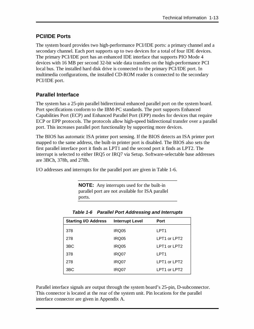
I/O addresses and interrupts for the parallel port are given in Table 1-6.
NOTE: Any interrupts used for the built-inparallel port are not available for ISA parallelports.
Table 1-6 Parallel Port Addressing and Interrupts
Starting I/O Add ress Interrupt Level Port
378 IRQ05 LPT1
278 IRQ05 LPT1 or LPT2
3BC IRQ05 LPT1 or LPT2
378 IRQ07 LPT1
278 IRQ07 LPT1 or LPT2
3BC IRQ07 LPT1 or LPT2
Parallel interface signals are output through the system board’s 25-pin, D-subconnector.This connector is located at the rear of the system unit. Pin locations for the parallelinterface connector are given in Appendix A.
1-14 Technical Information
Serial Interface
The system has two 16C550 UART-compatible serial ports (COM1 and COM2) integratedon the I/O controller. The serial ports support the standard RS-232C interface and the IRinterface (see Table 1-7). The buffered high-speed serial ports support transfer rates up to19.2 KB. These ports allow the installation of high-speed serial devices for faster datatransfer rates.
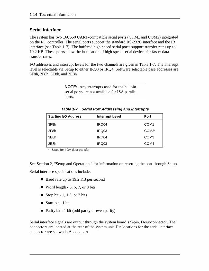
I/O addresses and interrupt levels for the two channels are given in Table 1-7. The interruptlevel is selectable via Setup to either IRQ3 or IRQ4. Software selectable base addresses are3F8h, 2F8h, 3E8h, and 2E8h.
NOTE: Any interrupts used for the built-inserial ports are not available for ISA parallelports.
Table 1-7 Serial Port Addressing and Interrupts
Starting I/O Add ress Interrupt Level Port
3F8h IRQ04 COM1
2F8h IRQ03 COM2*
3E8h IRQ04 COM3
2E8h IRQ03 COM4
* Used for IrDA data transfer
See Section 2, “Setup and Operation,” for information on resetting the port through Setup.
Serial interface specifications include:
� Baud rate up to 19.2 KB per second
� Word length - 5, 6, 7, or 8 bits
� Stop bit - 1, 1.5, or 2 bits
� Start bit - 1 bit
� Parity bit - 1 bit (odd parity or even parity).
Serial interface signals are output through the system board’s 9-pin, D-subconnector. Theconnectors are located at the rear of the system unit. Pin locations for the serial interfaceconnector are shown in Appendix A.
Technical Information 1-15
Infrared Interface
The I/O controller incorporates an infrared interface that provides two-way wirelesscommunication through the IR window (port) on the front of the system. The interface usesinfrared as the transmission medium instead of a traditional serial cable.
The IR port permits transfer of files to or from portable devices such as laptops andpersonal digital assistant (PDA) products using Puma TranXit applications software(Windows 95 only) or other software supporting IrDA data transfer. The port supports datatransfers at 115 Kbps from a distance of 1 meter (3 feet 3 inches).
The IR port uses the system’s COM2 serial port to transfer data. The port shares registersand function logic with COM2.
Universal Serial Bus Interface
The system board features two USB ports that permit the direct connection of two USBperipherals, one to each port. For more than two USB devices, connect an external hub toeither of the built-in ports. The system board fully supports the universal host controllerinterface (UHCI) and uses software drivers that are UHCI-compatible. The USB includesthe following features:
� Self-identifying peripherals that can be hot-plugged
� Automatic mapping of function to driver and configuration
� Support for synchronous and asynchronous transfer types over the same set ofwires
� Guaranteed bandwidth and low latencies appropriate for telephony, audio, andother applications
� Error handling and fault recovery mechanisms built into the protocol.
VIDEO BOARD
Depending on the model, the system features either a Matrox Mystique™ or a NumberNine Imagine 128 Series 2 video board that utilizes the PCI local bus. The vidoe boardcontains a graphics accelerator that integrates true color, digital video, and 3D effects into asingle chip and supports 2 MB (Matrox Mystique) or 4 MB (Number Nine Imagine) ofvideo memory. The 3D graphics engine renders 3D applications in photo-realistic colorsand textures for manipulatation in real time.
In addition to the standard VGA connector, a video feature connector is supplied on theMatrox Mystique video board. The following subsections provide information about thegraphics features.
1-16 Technical Information
Video Support
Matrox Mystique configurations come with 2 MB of video memory on the video board,upgradeable to 4 MB of video memory using a video upgrade module. Number NineImagine 128 Series 2 configurations come with 4 MB of video memory (not upgradable).
The default video mode is 800 by 600 pixels with 256 colors. To change the default videoresolution, see “Changing Display Properties” in Section 2.
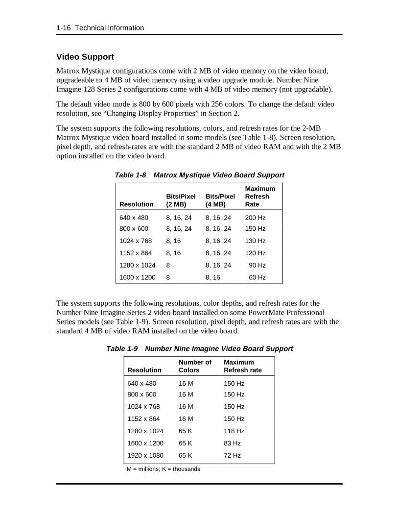
The system supports the following resolutions, colors, and refresh rates for the 2-MBMatrox Mystique video board installed in some models (see Table 1-8). Screen resolution,pixel depth, and refresh-rates are with the standard 2 MB of video RAM and with the 2 MBoption installed on the video board.
Table 1-8 Matrox Mystique Video Board Support
Resolution
Bits/Pixel(2 MB)
Bits/Pixel(4 MB)
MaximumRefreshRate
640 x 480 8, 16, 24 8, 16, 24 200 Hz
800 x 600 8, 16, 24 8, 16, 24 150 Hz
1024 x 768 8, 16 8, 16, 24 130 Hz
1152 x 864 8, 16 8, 16, 24 120 Hz
1280 x 1024 8 8, 16, 24 90 Hz
1600 x 1200 8 8, 16 60 Hz
The system supports the following resolutions, color depths, and refresh rates for theNumber Nine Imagine Series 2 video board installed on some PowerMate ProfessionalSeries models (see Table 1-9). Screen resolution, pixel depth, and refresh rates are with thestandard 4 MB of video RAM installed on the video board.
Table 1-9 Number Nine Imagine Video Board Support
Resolution
Number ofColors
MaximumRefresh rate
640 x 480 16 M 150 Hz
800 x 600 16 M 150 Hz
1024 x 768 16 M 150 Hz
1152 x 864 16 M 150 Hz
1280 x 1024 65 K 118 Hz
1600 x 1200 65 K 83 Hz
1920 x 1080 65 K 72 Hz
M = millions; K = thousands
Technical Information 1-17
Video Playback
The video board’s advanced video playback acceleration provides full-screen playback ofMPEG and AVI video clips.
The graphics engine delivers a full-screen, smooth display of motion video data up to30 frames per second (fps). Support includes:
� MPEG-1 or MPEG-2
� Active Movie
� Video for Windows.
MPEG is a compression/decompression standard developed by a professional video groupcalled the Motion Picture Experts Group. MPEG produces full-screen, 30-frames-per-second, broadcast-quality digital video.
The video board hardware accelerates color space conversion and video upscaling to deliverhigh quality MPEG and AVI video playback and true multimedia functionality.
AUDIO
A Yamaha OPL3-SA3 (YMF715) audio CODEC device is integrated on the system board.The device provides 16-bit stereo, Sound Blaster Pro-compatible audio. The system boardprovides a line in jack, line out jack, speaker jack, microphone jack, and a musicalinstrument device interface (MIDI) connector for the installation of a MIDI/Joystick kit.
The sound system is standard and consists of the following features:
� 16-bit audio multimedia CODEC and Yamaha OPL3 FM synthesizer
� digital audio and analog mixing functions, including stereo analog-to-digital anddigital-to-analog converters, analog mixing, anti-aliasing and reconstructionfilters, line and microphone level inputs, digital audio compression, and full digitalcontrol of mixer and volume control functions
� Adlib, Sound Blaster Pro, Windows Sound System, and MPU-401 compatibility
� plug and play compatibility.
1-18 Technical Information
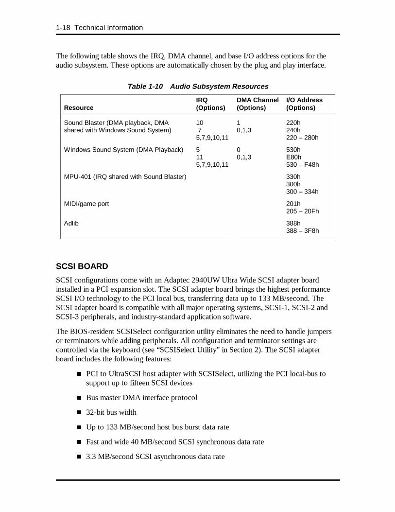
The following table shows the IRQ, DMA channel, and base I/O address options for theaudio subsystem. These options are automatically chosen by the plug and play interface.
Table 1-10 Audio Subsystem Resources
Resource
IRQ(Options)
DMA Channel(Options)
I/O Add ress(Options)
Sound Blaster (DMA playback, DMAshared with Windows Sound System)
10 75,7,9,10,11
10,1,3
220h240h220 – 280h
Windows Sound System (DMA Playback) 5115,7,9,10,11
00,1,3
530hE80h530 – F48h
MPU-401 (IRQ shared with Sound Blaster) 330h300h300 – 334h
MIDI/game port 201h205 – 20Fh
Adlib 388h388 – 3F8h
SCSI BOARD
SCSI configurations come with an Adaptec 2940UW Ultra Wide SCSI adapter boardinstalled in a PCI expansion slot. The SCSI adapter board brings the highest performanceSCSI I/O technology to the PCI local bus, transferring data up to 133 MB/second. TheSCSI adapter board is compatible with all major operating systems, SCSI-1, SCSI-2 andSCSI-3 peripherals, and industry-standard application software.
The BIOS-resident SCSISelect configuration utility eliminates the need to handle jumpersor terminators while adding peripherals. All configuration and terminator settings arecontrolled via the keyboard (see “SCSISelect Utility” in Section 2). The SCSI adapterboard includes the following features:
� PCI to UltraSCSI host adapter with SCSISelect, utilizing the PCI local-bus tosupport up to fifteen SCSI devices
� Bus master DMA interface protocol
� 32-bit bus width
� Up to 133 MB/second host bus burst data rate
� Fast and wide 40 MB/second SCSI synchronous data rate
� 3.3 MB/second SCSI asynchronous data rate
Technical Information 1-19
� SCSI-1, SCSI-2, SCSI-3, and Wide UltraSCSI device protocol
� Advanced SCSI features including multi-threaded I/O (up to 255 taskssimultaneously), scatter/gather, tagged command queuing, disconnect/reconnect,and synchronous and asynchronous data transfer
� Extended translation scheme supports up to eight GB per disk
� Drivers may be single-ended, active, or programmable via the SCSISelectconfiguration utility.
DISKETTE DRIVE
Up to two diskette drives are supported in the system. The installed 3 1/2-inch diskettedrive is connected by a single ribbon cable with two drive connectors. The diskette drivecable plugs directly into the system board. Typically, there are no switches or jumpers thatneed to be set, both diskette drives are terminated, and the cable determines drive A and B.Connector locations are given in Appendix A.
HARD DISK DRIVE
Up to four IDE hard drives are supported in the system (non-SCSI configurations). In theSCSI configuration, up to 15 SCSI devices (disk drives, CD-ROM drives, scanners, tapebackups) are supported by the Ultra Wide SCSI adapter board. Two SCSI devices can beinstalled internally in the system chassis.
IDE Hard Drives
The system board has two IDE/PCI interface connectors (primary and secondary) forconnecting IDE storage devices such as hard disk drives. Each connector supports up totwo IDE devices. Connector locations are given in Appendix A.
All systems ship with one internal 3 1/2-inch hard disk (1-inch high, thin-height) installedbehind the front panel in the bottom slot in the drive cage. The three-connector hard diskdrive cable plugs into the primary connector on the system board. An optional second harddrive can be connected to the middle connector on the primary IDE cable. A third harddrive (in a 5 1/4-inch accessible slot) can be connected to the middle connector on thesecondary IDE cable.
NOTE: The first connector on the secondaryIDE cable connects the standard CD-ROMreader to the system board.
The standard hard disk drive is set as the master device on the primary IDE/PCI port (seeFigure 1-3 for jumper settings). Use the Storage Device Installation procedures in Section 3when installing optional devices.
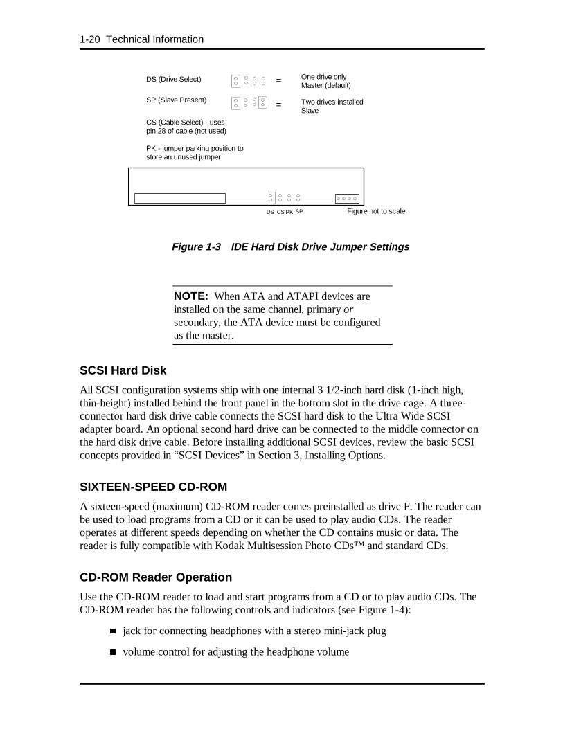
1-20 Technical Information
Figure 1-3 IDE Hard Disk Drive Jumper Settings
NOTE: When ATA and ATAPI devices areinstalled on the same channel, primary orsecondary, the ATA device must be configuredas the master.
SCSI Hard Disk
All SCSI configuration systems ship with one internal 3 1/2-inch hard disk (1-inch high,thin-height) installed behind the front panel in the bottom slot in the drive cage. A three-connector hard disk drive cable connects the SCSI hard disk to the Ultra Wide SCSIadapter board. An optional second hard drive can be connected to the middle connector onthe hard disk drive cable. Before installing additional SCSI devices, review the basic SCSIconcepts provided in “SCSI Devices” in Section 3, Installing Options.
SIXTEEN-SPEED CD-ROM
A sixteen-speed (maximum) CD-ROM reader comes preinstalled as drive F. The reader canbe used to load programs from a CD or it can be used to play audio CDs. The readeroperates at different speeds depending on whether the CD contains music or data. Thereader is fully compatible with Kodak Multisession Photo CDs™ and standard CDs.
CD-ROM Reader Operation
Use the CD-ROM reader to load and start programs from a CD or to play audio CDs. TheCD-ROM reader has the following controls and indicators (see Figure 1-4):
� jack for connecting headphones with a stereo mini-jack plug
� volume control for adjusting the headphone volume
One drive onlyMaster (default)
CS (Cable Select) - usespin 28 of cable (not used)
Two drives installedSlave
Figure not to scale
PK - jumper parking position tostore an unused jumper
DS CS PK SP
DS (Drive Select) =
=SP (Slave Present)

Technical Information 1-21
� busy lamp that lights during read operations
� CD tray that opens and closes when the open/close button is pressed
� open/close button for opening or closing the CD tray when the power is on
� emergency eject hole in the front panel for manually opening the CD tray if poweris lost. Insert a paper clip into the hole and press inward to open the tray.
Figure 1-4 CD-ROM Reader Controls and Indicators
To load a disc in the sixteen-speed CD-ROM reader, follow these steps.
1. Press the open/close button. The CD tray opens.
2. Put the CD, printed side up, into the tray.
3. Press the open/close button. The tray closes.
4. To remove the disc, press the open/close button. The tray opens, allowingremoval of the disc.
CD-ROM Reader Settings
The reader is set as the master device on the secondary IDE/PCI port (see Figure 1-5). Fordetails about CD-ROM jumper settings and connector descriptions, see Appendix D.
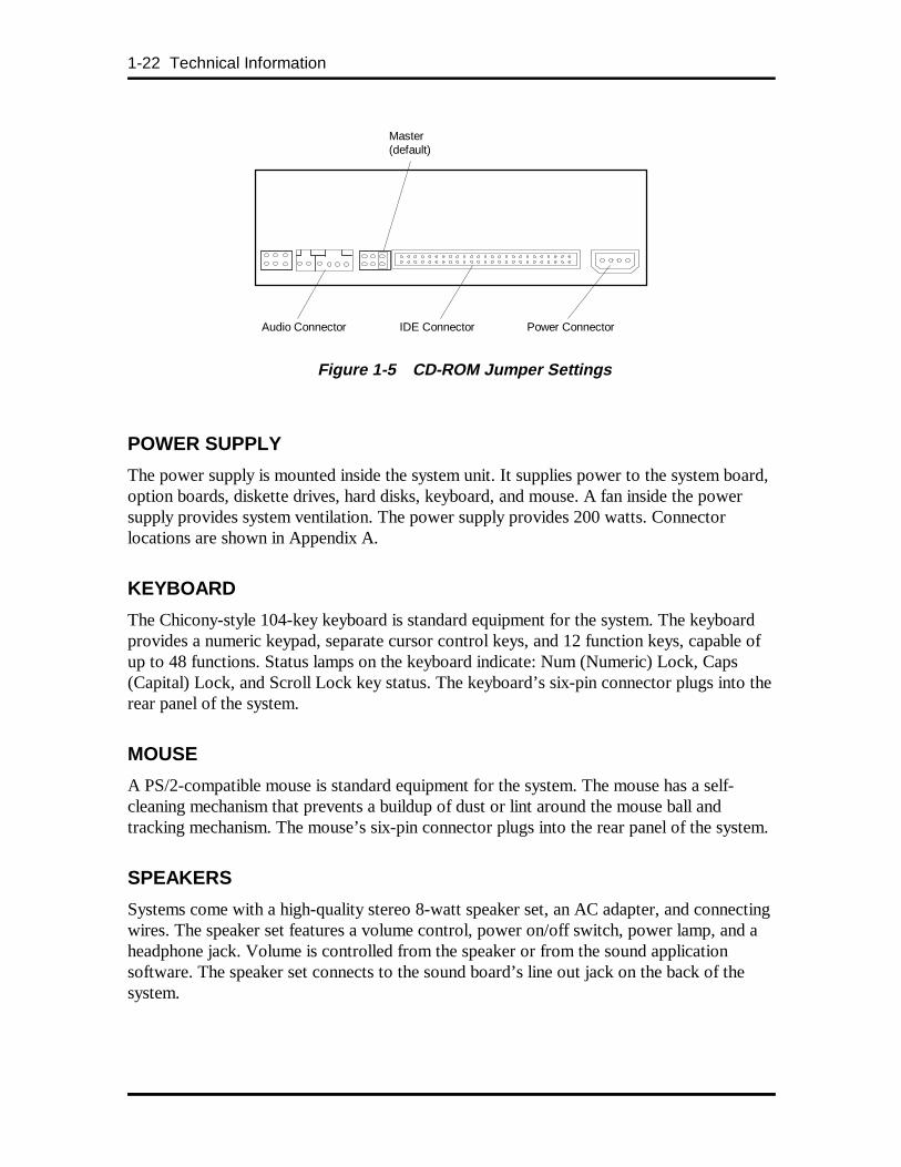
1-22 Technical Information
Figure 1-5 CD-ROM Jumper Settings
POWER SUPPLY
The power supply is mounted inside the system unit. It supplies power to the system board,option boards, diskette drives, hard disks, keyboard, and mouse. A fan inside the powersupply provides system ventilation. The power supply provides 200 watts. Connectorlocations are shown in Appendix A.
KEYBOARD
The Chicony-style 104-key keyboard is standard equipment for the system. The keyboardprovides a numeric keypad, separate cursor control keys, and 12 function keys, capable ofup to 48 functions. Status lamps on the keyboard indicate: Num (Numeric) Lock, Caps(Capital) Lock, and Scroll Lock key status. The keyboard’s six-pin connector plugs into therear panel of the system.
MOUSE
A PS/2-compatible mouse is standard equipment for the system. The mouse has a self-cleaning mechanism that prevents a buildup of dust or lint around the mouse ball andtracking mechanism. The mouse’s six-pin connector plugs into the rear panel of the system.
SPEAKERS
Systems come with a high-quality stereo 8-watt speaker set, an AC adapter, and connectingwires. The speaker set features a volume control, power on/off switch, power lamp, and aheadphone jack. Volume is controlled from the speaker or from the sound applicationsoftware. The speaker set connects to the sound board’s line out jack on the back of thesystem.
IDE Connector Power Connector
Master(default)
Audio Connector
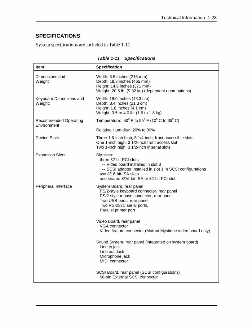
Technical Information 1-23
SPECIFICATIONS
System specifications are included in Table 1-11.
Table 1-11 Specifications
Item Specification
Dimensions andWeight
Width: 8.5 inches (215 mm)Depth: 18.3 inches (465 mm)Height: 14.6 inches (371 mm)Weight: 20.5 lb. (9.32 kg) (dependent upon options)
Keyboard Dimensions andWeight:
Width: 19.0 inches (48.3 cm)Depth: 8.4 inches (21.3 cm)Height: 1.6 inches (4.1 cm)Weight: 3.5 to 4.0 lb. (1.6 to 1.8 kg)
Recommended OperatingEnvironment
Temperature: 50o F to 95o F (10o C to 35o C)
Relative Humidity: 20% to 80%
Device Slots Three 1.6-inch high, 5 1/4-inch, front accessible slotsOne 1-inch high, 3 1/2-inch front access slotTwo 1-inch high, 3 1/2-inch internal slots
Expansion Slots Six slots: three 32-bit PCI slots
-- Video board installed in slot 3-- SCSI adapter installed in slot 1 in SCSI configurations
two 8/16-bit ISA slots one shared 8/16-bit ISA or 32-bit PCI slot
Peripheral Interface System Board, rear panel PS/2-style keyboard connector, rear panel PS/2-style mouse connector, rear panel Two USB ports, rear panel Two RS-232C serial ports, Parallel printer port
Video Board, rear panel VGA connector Video feature connector (Matrox Mystique video board only)
Sound System, rear panel (integrated on system board) Line in jack Line out Jack Microphone jack MIDI connector
SCSI Board, rear panel (SCSI configurations) 68-pin External SCSI connector
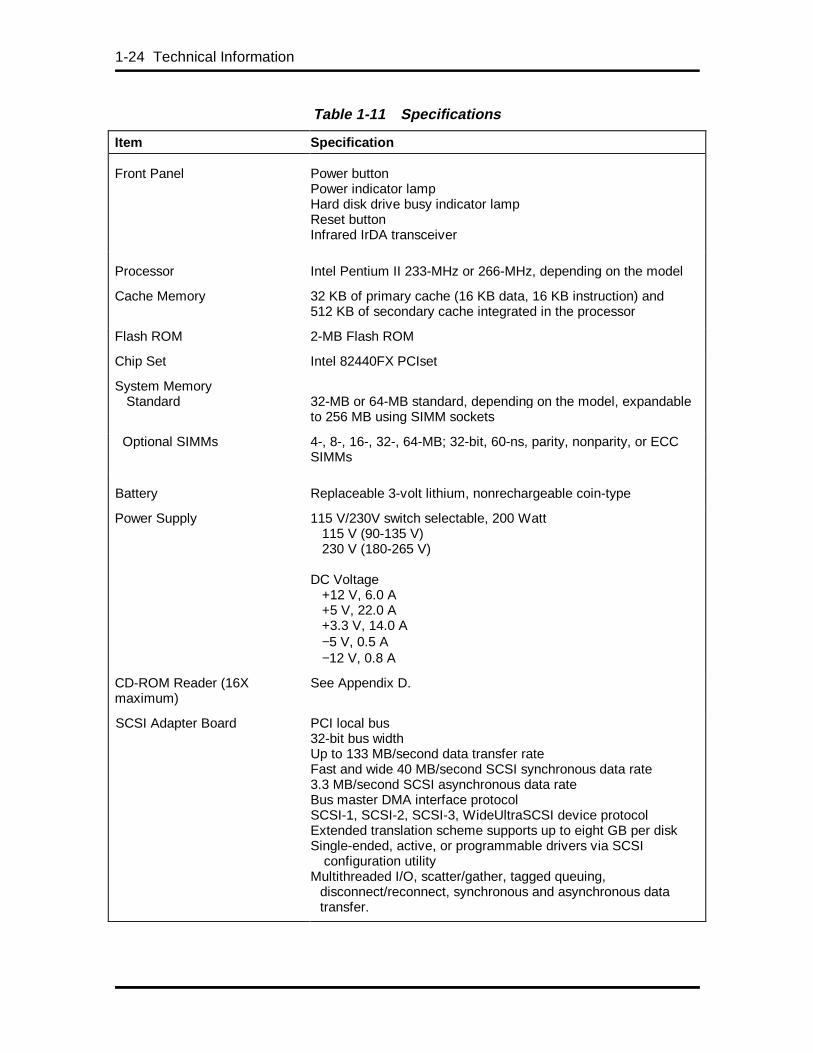
1-24 Technical Information
Table 1-11 Specifications
Item Specification
Front Panel Power buttonPower indicator lampHard disk drive busy indicator lampReset buttonInfrared IrDA transceiver
Processor Intel Pentium II 233-MHz or 266-MHz, depending on the model
Cache Memory 32 KB of primary cache (16 KB data, 16 KB instruction) and512 KB of secondary cache integrated in the processor
Flash ROM 2-MB Flash ROM
Chip Set Intel 82440FX PCIset
System Memory Standard
32-MB or 64-MB standard, depending on the model, expandableto 256 MB using SIMM sockets
Optional SIMMs 4-, 8-, 16-, 32-, 64-MB; 32-bit, 60-ns, parity, nonparity, or ECCSIMMs
Battery Replaceable 3-volt lithium, nonrechargeable coin-type
Power Supply 115 V/230V switch selectable, 200 Watt 115 V (90-135 V) 230 V (180-265 V)
DC Voltage +12 V, 6.0 A +5 V, 22.0 A +3.3 V, 14.0 A −5 V, 0.5 A −12 V, 0.8 A
CD-ROM Reader (16Xmaximum)
See Appendix D.
SCSI Adapter Board PCI local bus32-bit bus widthUp to 133 MB/second data transfer rateFast and wide 40 MB/second SCSI synchronous data rate3.3 MB/second SCSI asynchronous data rateBus master DMA interface protocolSCSI-1, SCSI-2, SCSI-3, WideUltraSCSI device protocolExtended translation scheme supports up to eight GB per diskSingle-ended, active, or programmable drivers via SCSI configuration utilityMultithreaded I/O, scatter/gather, tagged queuing,
disconnect/reconnect, synchronous and asynchronous data transfer.
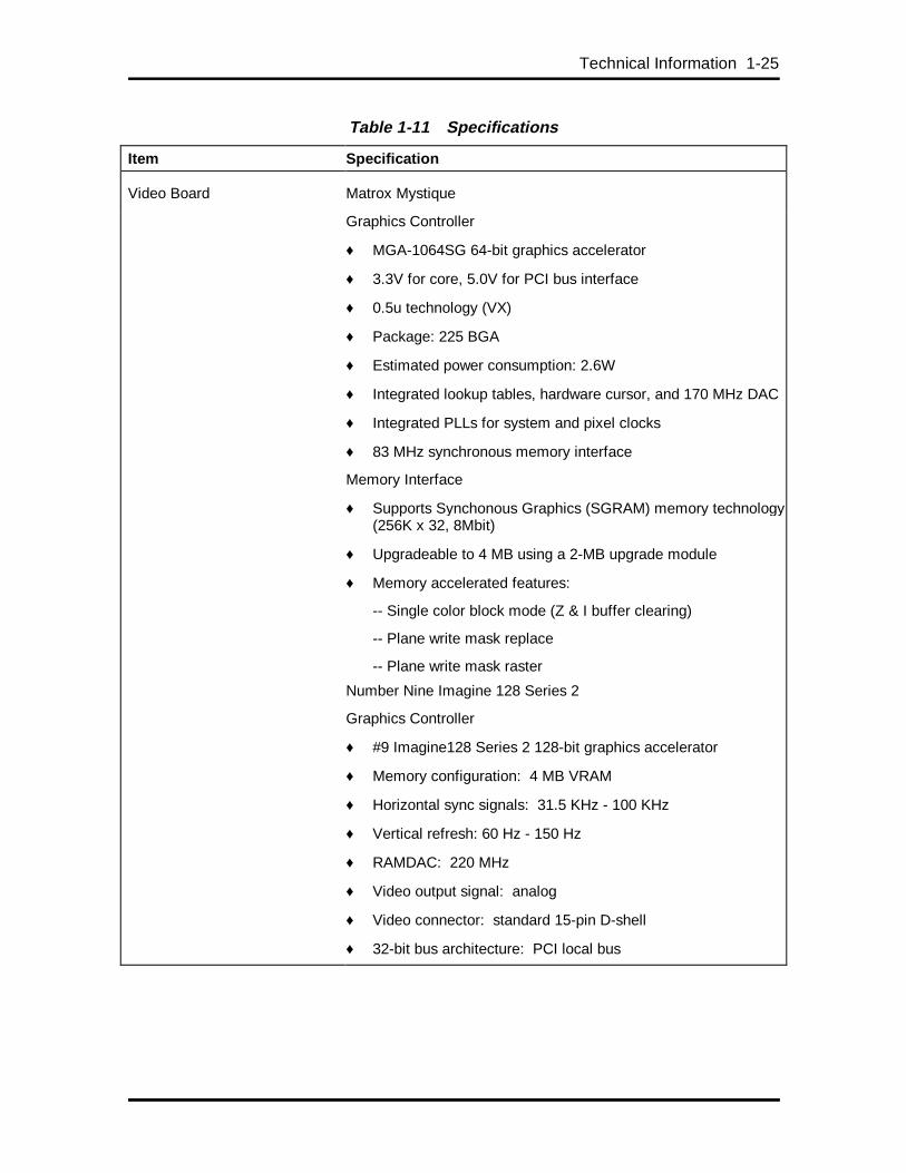
Technical Information 1-25
Table 1-11 Specifications
Item Specification
Video Board Matrox Mystique
Graphics Controller
♦ MGA-1064SG 64-bit graphics accelerator
♦ 3.3V for core, 5.0V for PCI bus interface
♦ 0.5u technology (VX)
♦ Package: 225 BGA
♦ Estimated power consumption: 2.6W
♦ Integrated lookup tables, hardware cursor, and 170 MHz DAC
♦ Integrated PLLs for system and pixel clocks
♦ 83 MHz synchronous memory interface
Memory Interface
♦ Supports Synchonous Graphics (SGRAM) memory technology(256K x 32, 8Mbit)
♦ Upgradeable to 4 MB using a 2-MB upgrade module
♦ Memory accelerated features:
-- Single color block mode (Z & I buffer clearing)
-- Plane write mask replace
-- Plane write mask raster
Number Nine Imagine 128 Series 2
Graphics Controller
♦ #9 Imagine128 Series 2 128-bit graphics accelerator
♦ Memory configuration: 4 MB VRAM
♦ Horizontal sync signals: 31.5 KHz - 100 KHz
♦ Vertical refresh: 60 Hz - 150 Hz
♦ RAMDAC: 220 MHz
♦ Video output signal: analog
♦ Video connector: standard 15-pin D-shell
♦ 32-bit bus architecture: PCI local bus
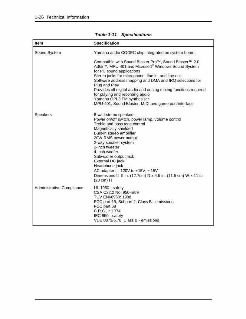
1-26 Technical Information
Table 1-11 Specifications
Item Specification
Sound System Yamaha audio CODEC chip integrated on system board:
Compatible with Sound Blaster Pro™, Sound Blaster™ 2.0,Adlib™, MPU-401 and Microsoft® Windows Sound Systemfor PC sound applicationsStereo jacks for microphone, line in, and line outSoftware address mapping and DMA and IRQ selections forPlug and PlayProvides all digital audio and analog mixing functions requiredfor playing and recording audioYamaha OPL3 FM synthesizerMPU-401, Sound Blaster, MIDI and game port interface
Speakers 8-watt stereo speakersPower on/off switch, power lamp, volume controlTreble and bass tone controlMagnetically shieldedBuilt-in stereo amplifier20W RMS power output2-way speaker system2-inch tweeter4-inch wooferSubwoofer output jackExternal DC jackHeadphone jackAC adapter 120V to +15V, − 15VDimensions 5 in. (12.7cm) D x 4.5 in. (11.5 cm) W x 11 in.(28 cm) H
Administrative Compliance UL 1950 - safetyCSA C22.2 No. 950-m89TUV EN60950: 1988FCC part 15, Subpart J, Class B - emissionsFCC part 68C.R.C., c.1374IEC 950 - safetyVDE 0871/6.78, Class B - emissions
Section 2
Setup and Operation
This section provides information on hardware setup and operation for the PowerMateProfessional Series systems. Setup includes unpacking, setting up, and powering on thesystem. Operation includes information on loading the Setup utility program for configuringsystem parameters. This section also provides information on using the NECCSD BulletinBoard Service (BBS) and running the BIOS update utility. Information on using theCD Restore, Driver CD, and Applications CD programs is provided at the end of thissection.
NOTE: Support information (includingtelephone numbers for the NECCSD technicalsupport center and Internet addresses for theNECCSD World Wide Web and FTP sites) isprovided in Section 4.
UNPACKING AND REPACKING
Find an area away from devices that generate magnetic fields (electric motors, transformers,etc.). Place the carton on a sturdy surface, and carefully unpack the system. The cartoncontents include the system unit, keyboard, mouse, power cord, various CDs, one or morediskettes, and user documentation.
Repack the system using the original shipping carton and packing material. Part numbers forreplacement shipping cartons and packing material are included in “Illustrated PartsBreakdown” in Section 5.
SYSTEM SETUP
Unpack the contents of the shipping carton. The only other item needed to set up thecomputer is a VGA-compatible monitor. Use the following procedures to set up thecomputer.
Keyboard, Mouse, and Power Cable Connection
Set up the system components by making the following connections.
1. Set the voltage selector switch to 115V (U.S. and Canada) or 230V and plug thepower cord into the power socket (see Figure 2-1).
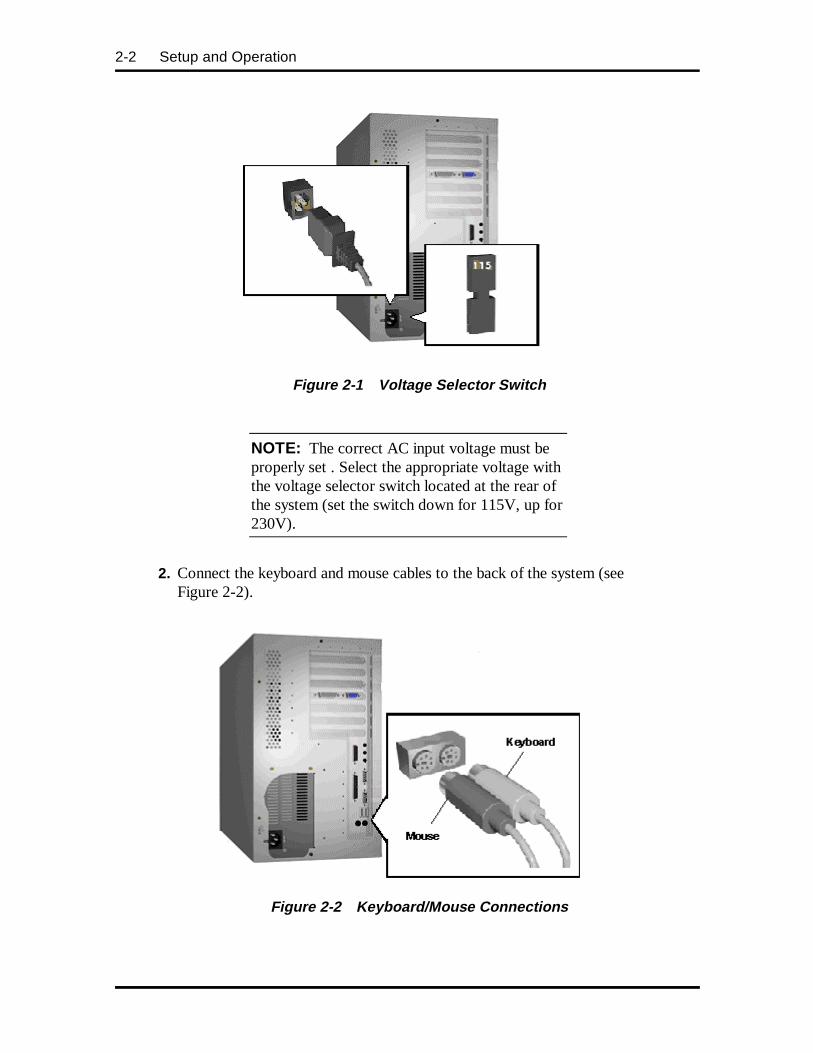
2-2 Setup and Operation
Figure 2-1 Voltage Selector Switch
NOTE: The correct AC input voltage must beproperly set . Select the appropriate voltage withthe voltage selector switch located at the rear ofthe system (set the switch down for 115V, up for230V).
2. Connect the keyboard and mouse cables to the back of the system (seeFigure 2-2).
Figure 2-2 Keyboard/Mouse Connections
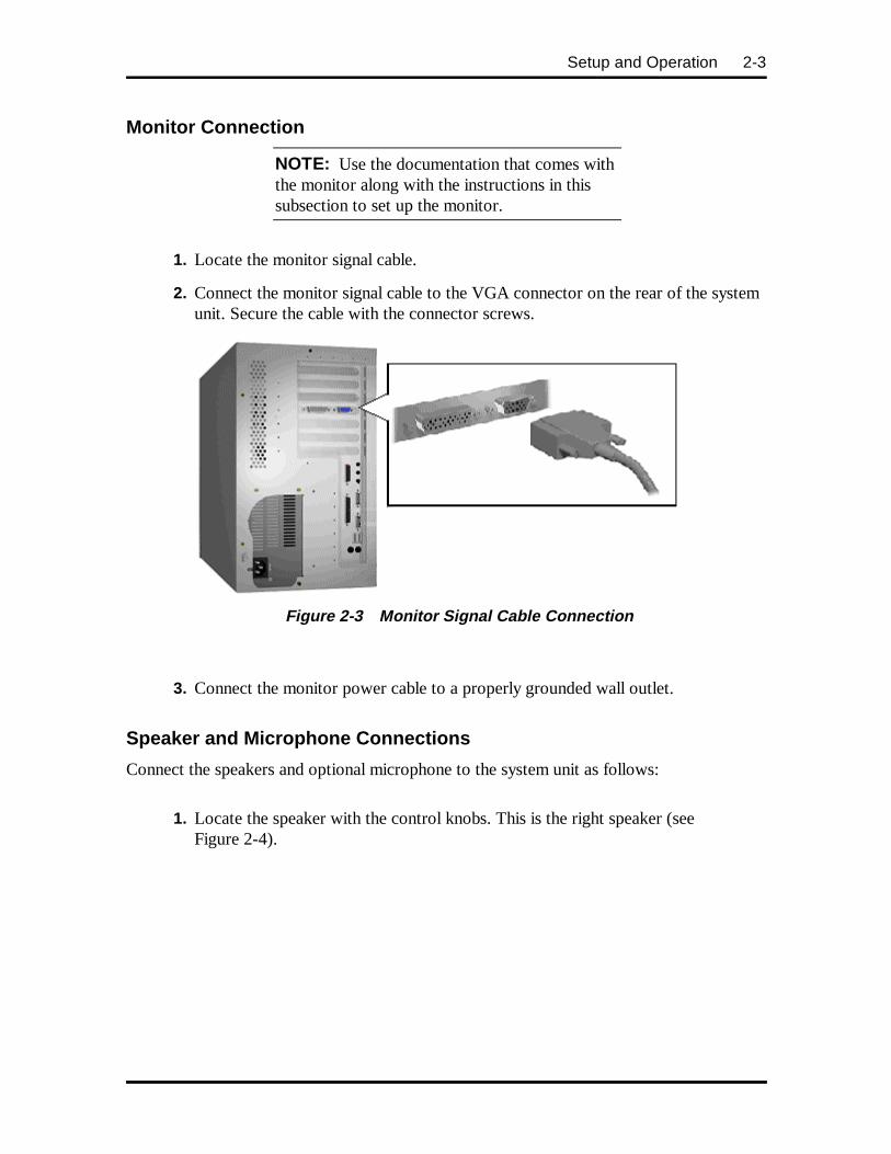
Setup and Operation 2-3
Monitor Connection
NOTE: Use the documentation that comes withthe monitor along with the instructions in thissubsection to set up the monitor.
1. Locate the monitor signal cable.
2. Connect the monitor signal cable to the VGA connector on the rear of the systemunit. Secure the cable with the connector screws.
Figure 2-3 Monitor Signal Cable Connection
3. Connect the monitor power cable to a properly grounded wall outlet.
Speaker and Microphone Connections
Connect the speakers and optional microphone to the system unit as follows:
1. Locate the speaker with the control knobs. This is the right speaker (seeFigure 2-4).
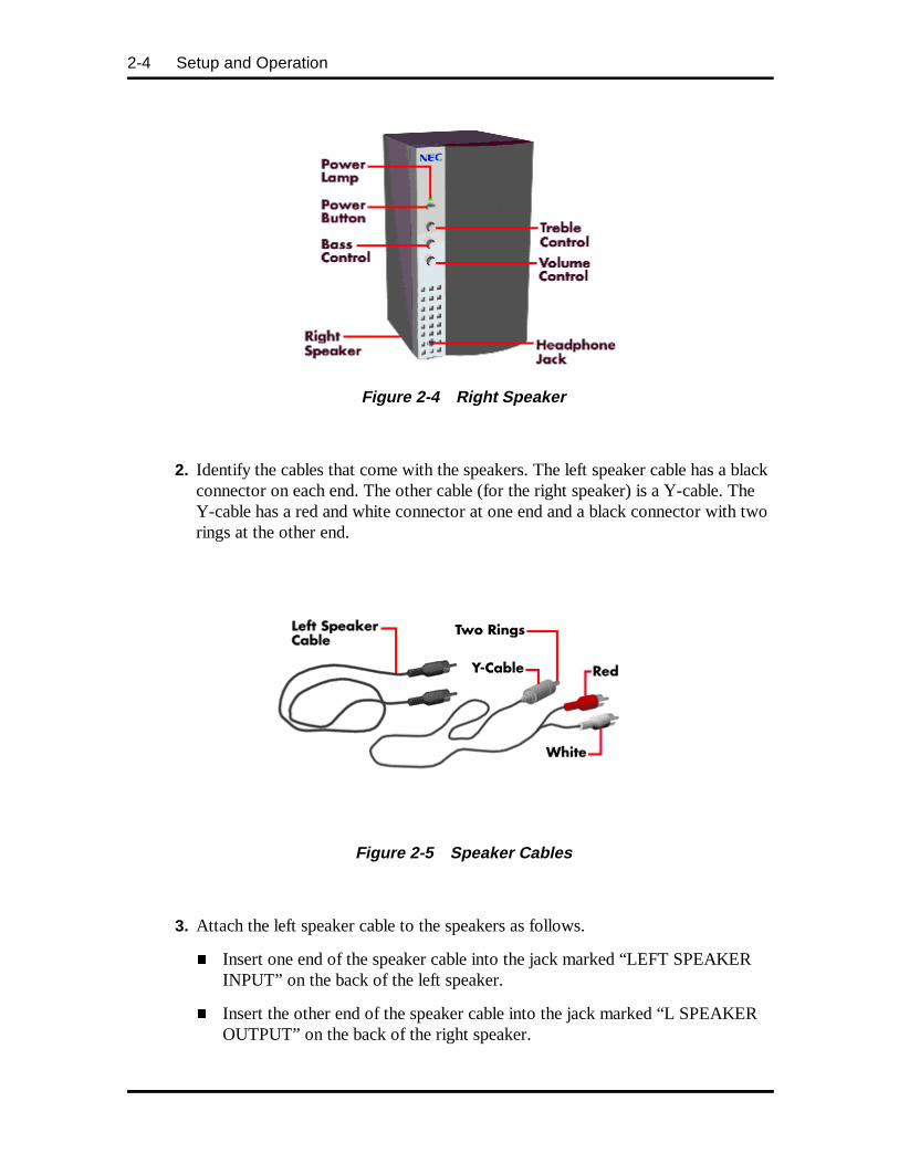
2-4 Setup and Operation
Figure 2-4 Right Speaker
2. Identify the cables that come with the speakers. The left speaker cable has a blackconnector on each end. The other cable (for the right speaker) is a Y-cable. TheY-cable has a red and white connector at one end and a black connector with tworings at the other end.
Figure 2-5 Speaker Cables
3. Attach the left speaker cable to the speakers as follows.
� Insert one end of the speaker cable into the jack marked “LEFT SPEAKERINPUT” on the back of the left speaker.
� Insert the other end of the speaker cable into the jack marked “L SPEAKEROUTPUT” on the back of the right speaker.

Setup and Operation 2-5
Figure 2-6 Connecting the Two Speakers
4. Attach the Y-cable as follows.
� Insert the red connector into the red jack marked “RIGHT LINE IN” on theback of the right speaker.
� Insert the white connector into the white jack marked “LEFT LINE IN” onthe back of the right speaker.
� Insert the other end of the cable into the Line Out jack on the rear of thesystem unit (see Figure 2-7).
5. Connect an optional microphone cable to the Microphone In connector on therear of the system unit (see Figure 2-7).
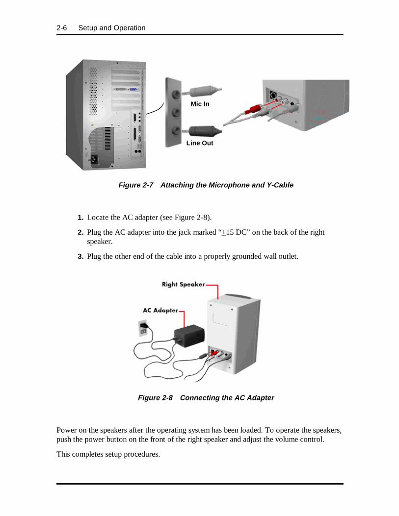
2-6 Setup and Operation
Figure 2-7 Attaching the Microphone and Y-Cable
1. Locate the AC adapter (see Figure 2-8).
2. Plug the AC adapter into the jack marked “+15 DC” on the back of the rightspeaker.
3. Plug the other end of the cable into a properly grounded wall outlet.
Figure 2-8 Connecting the AC Adapter
Power on the speakers after the operating system has been loaded. To operate the speakers,push the power button on the front of the right speaker and adjust the volume control.
This completes setup procedures.
Line Out
Mic In
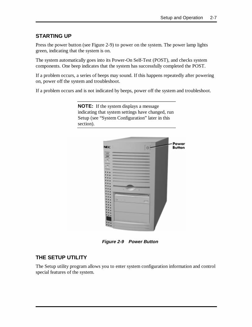
Setup and Operation 2-7
STARTING UP
Press the power button (see Figure 2-9) to power on the system. The power lamp lightsgreen, indicating that the system is on.
The system automatically goes into its Power-On Self-Test (POST), and checks systemcomponents. One beep indicates that the system has successfully completed the POST.
If a problem occurs, a series of beeps may sound. If this happens repeatedly after poweringon, power off the system and troubleshoot.
If a problem occurs and is not indicated by beeps, power off the system and troubleshoot.
NOTE: If the system displays a messageindicating that system settings have changed, runSetup (see “System Configuration” later in thissection).
Figure 2-9 Power Button
THE SETUP UTILITY
The Setup utility program allows you to enter system configuration information and controlspecial features of the system.
2-8 Setup and Operation
NOTE: The system ships from the factory withthe correct system parameters for theconfiguration. Unless you add optional hardware,you do not need to run Setup to operate thesystem. However, you might wish to run theSetup utility to set features that customize thesystem, such as security features.
System configuration information is stored in nonvolatile memory. A nonvolatile memorydevice retains its data when system power is turned off. Nonvolatile memory in the systemis a complementary metal-oxide semiconductor (CMOS) chip backed up by a battery on thesystem board. The battery supplies continuous power to CMOS memory and maintainsconfiguration information when system power is off (see “Battery Replacement” inChapter 4).
NOTE: NEC recommends that you print out orwrite down the current Setup parameters andstore the information in a safe place. This letsyou restore the system to the current parametersif you ever need to replace the battery.
When to Use Setup
The Setup utility lets you view and set system parameters. Use the Setup utility program:
� to set the time and date
� to update or check system parameters when you add or remove expansion options
� to change or set power management features
� to correct a hardware discrepancy when the Power-On-Self-Test (POST) displaysan error message and prompts you to run Setup
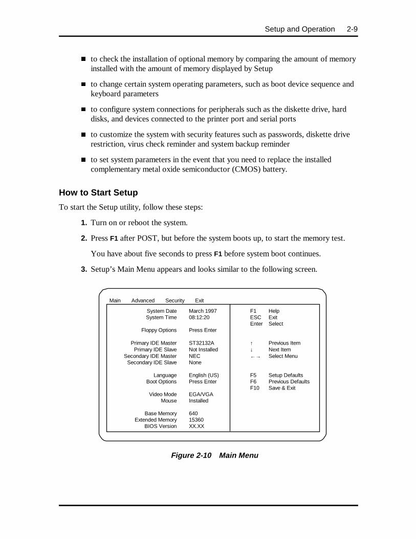
Setup and Operation 2-9
� to check the installation of optional memory by comparing the amount of memoryinstalled with the amount of memory displayed by Setup
� to change certain system operating parameters, such as boot device sequence andkeyboard parameters
� to configure system connections for peripherals such as the diskette drive, harddisks, and devices connected to the printer port and serial ports
� to customize the system with security features such as passwords, diskette driverestriction, virus check reminder and system backup reminder
� to set system parameters in the event that you need to replace the installedcomplementary metal oxide semiconductor (CMOS) battery.
How to Start Setup
To start the Setup utility, follow these steps:
1. Turn on or reboot the system.
2. Press F1 after POST, but before the system boots up, to start the memory test.
You have about five seconds to press F1 before system boot continues.
3. Setup’s Main Menu appears and looks similar to the following screen.
Figure 2-10 Main Menu
Main Advanced Security Exit
System Date March 1997 F1 Help System Time 08:12:20 ESC Exit Enter Select Floppy Options Press Enter Primary IDE Master ST32132A ↑ Previous Item Primary IDE Slave Not Installed ↓ Next Item Secondary IDE Master NEC ←→ Select Menu Secondary IDE Slave None Language English (US) F5 Setup Defaults Boot Options Press Enter F6 Previous Defaults F10 Save & Exit Video Mode EGA/VGA Mouse Installed Base Memory 640 Extended Memory 15360 BIOS Version XX.XX
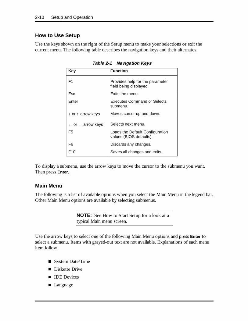
2-10 Setup and Operation
How to Use Setup
Use the keys shown on the right of the Setup menu to make your selections or exit thecurrent menu. The following table describes the navigation keys and their alternates.
Table 2-1 Navigation Keys
Key Function
F1 Provides help for the parameterfield being displayed.
Esc Exits the menu.
Enter Executes Command or Selectssubmenu.
↓ or ↑ arrow keys Moves cursor up and down.
← or → arrow keys Selects next menu.
F5 Loads the Default Configurationvalues (BIOS defaults).
F6 Discards any changes.
F10 Saves all changes and exits.
To display a submenu, use the arrow keys to move the cursor to the submenu you want.Then press Enter .
Main Menu
The following is a list of available options when you select the Main Menu in the legend bar.Other Main Menu options are available by selecting submenus.
NOTE: See How to Start Setup for a look at atypical Main menu screen.
Use the arrow keys to select one of the following Main Menu options and press Enter toselect a submenu. Items with grayed-out text are not available. Explanations of each menuitem follow.
� System Date/Time
� Diskette Drive
� IDE Devices
� Language
Setup and Operation 2-11
� Boot Options
� Video Mode
� Mouse
� Base Memory
� Extended Memory
� BIOS Version
System Date/Time
Use this menu to set the current time and date. The settings remain in memory even afteryou turn off the system power.
To set the date, highlight “date” and press Enter . Type the current day, month, and year indd/mm/yyyy format.
To set the time, highlight “time” and press Enter . Type the current hour, minute, andseconds in hh:mm:ss, 24-hour format. For example, type 13:30:00 for 1:30 P.M.
NOTE: The PowerMate Professional Seriesprovides Year 2000-support.
Diskette Drive
This menu selects the type of diskette drive in the system. Unless you are changing thehardware, you do not need to change the diskette drive (floppy) A or B settings.
If you add an optional 5 1/4-inch diskette drive to the system, select “Floppy B” and changethe parameter to “1.2 MB, 5.25 inch.”
IDE Devices
The standard hard disk drive (drive C:) shipped with the system is configured as “PrimaryIDE Master.” This field reports the presence of, and identification string reported by, up tofour physical IDE drives (two on each PCI/IDE connector). When the cursor is placed onone of these fields and selected by pressing the Enter key, the IDE Device Submenu appearsallowing the drive parameters to be set.
Jumper settings on the IDE device must be set to the master or slave device (see thedocumentation that comes with the device).
2-12 Setup and Operation
IDE Device Configuration Submenu
The Hard Disk Submenu lets you check or change the following hard disk drive parameters:
� IDE Device Configuration
Number of Cylinders
Number of Heads
Number of Sectors
Maximum Capacity
� IDE Translation Mode
� Multiple Sector Setting
� Fast Programmed I/O Modes.
IDE Device Configuration
The system is shipped with default as “Auto Configured” selected in this submenu. Thesystem then automatically detects the hard disk type and sets the remaining parameters.
If the IDE hard disk does not feature auto IDE type detection or the IDE hard disk wasformatted on another system with parameters different than those reported by the drive, youneed to select “User-Definable,” and set the “Number of Cylinders,” “Number of Heads,”“Number of Sectors,” and “Maximum Capacity.”
IDE Translation Mode
The IDE Translation Mode parameter controls the way in which the BIOS interacts withthe drive in terms of drive geometry. Proper choice is dependent upon the drive’s size,capabilities, and the operating system (OS) used. The following choices are available:
� Standard CHS − is the translation mode that has been in use for years. Its uselimits IDE capacity to a maximum of 528 MB regardless of the size of the driveused.
� Logical Block − mode overcomes the 528 MB maximum size limitations imposedby the Standard CHS mode. It should be used only when the drive supportslogical block addressing (LBA), and the OS supports LBA, or uses the BIOS toaccess the disk.
� Extended CHS − mode also overcomes the 528 MB maximum size limitationsimposed by the Standard CHS mode. It can be used with drives that are largerthan 528 MB, but does not support the LBA mode.
Setup and Operation 2-13
� Auto Detected (default) − allows the BIOS to examine the drive and determinethe optimal mode. The first choice is to utilize Logical Block mode if it issupported by the drive. The second choice is to utilize Extended CHS mode if thedrive topology allows its use. If neither of the above two methods is possible, thenStandard CHS mode is used.
CAUTION: When set to Auto Detected, theBIOS will detect what the drive is capable of, notthe translation mechanism that was used toformat the drive.
If a drive is run in a mode other than the mode inwhich it was partitioned and formatted,unpredictable results may occur, including dataloss.
Different OS have different abilities regarding IDE translation modes:
� UNIX − does not currently support either LBA or ECHS and must utilize theStandard CHS method. UNIX can support drives larger than 528 MB, but doesso in its own way.
� OS/2 2.1 and OS/2 WARP − can support LBA, ECHS, or Standard CHSmethods. Note that LBA support may require a switch setting on an OS/2 driverin order to operate in the mode.
� OS/2 2.0 and Novel Netware − can support either ECHS or Standard CHSmethods, but not LBA.
� DOS and Windows − can support LBA, ECHS, or Standard CHS methods. If the“Fast 32-bit IDE” option of Windows is utilized, make sure to use the StandardCHS setting only, unless a version of WDCDRV.386 is being used that supportsthis advanced geometry.
You will get better performance not using “Fast 32-bit IDE” if you are using a drive thatemploys Mode 3 PIO or greater on the PCI interface. However, you can use “Fast 32-bitIDE” to increase performance if you are using a version of WDCDRV.386 that supportsthese advanced modes.
Language
The installed language will appear in the Setup and BIOS text strings. English (US) is thedefault in the U. S. and Canada.
2-14 Setup and Operation
Boot Options
When the cursor is placed in the Boot Option field, you can select it by pressing Enter . TheBoot Options Submenu appears allowing parameters that affect the boot process to be set.
Boot Options Submenu
The Boot Options Submenu lets you check or change the following bootup parameters:
� Boot Sequence
� System Cache
� Boot Speed
� NumLock
� Speaker
� Setup Prompt
� Hard Disk Pre-Delay
� Typematic Rate Programming
� Power-on COM1 Ring.
Boot Sequence
The BIOS attempts to load the operating system in the sequence listed here. The defaultsare as follows:
� First boot device − CD-ROM
� Second boot device − diskette drive
� Third boot device − hard disk
� Fourth boot device − disabled.
System Cache
The default for the System Cache field is “Enabled.” This field controls both the primaryand secondary caches. Setting the system cache to “Disabled” will hurt performance. Thismight be required, however, when running software that utilizes software timing loops andneeds to be slowed down to execute properly.
Boot Speed
Boot speed refers to the system CPU cycles. The default boot speed is “Turbo.” “De-turbo”mode slows the CPU by disabling the system cache and adding increased refresh cycles.

Setup and Operation 2-15
NOTE: “De-turbo” does not reduce the CPUspeed to 8 MHz. If “De-turbo” is selected, it willautomatically “Disable” the System Cache.
NumLock
The NumLock field controls whether the NumLock key on the keyboard will be “On” or“Off” at bootup. The default is “Off.”
Speaker
The Speaker field allows you to turn the onboard speaker (for multimedia systems) on oroff. The options are “Enabled” or “Disabled.” The default for the Speaker field is“Enabled.”
Setup Prompt
The Setup Prompt field allows you to disable the “Press <F1> Key To Enter Setup”message displayed during POST. It does not control access, just the message. This field canbe either “Enabled” or “Disabled.” The default is “Enabled.”
Hard Disk Pre-Delay
The Hard Disk Pre-Delay field causes the BIOS to wait a specified time before accessingthe first hard disk drive. Setting a pre-delay provides the system with some time to identifyany additional drives before the standard hard drive initializes. The default is “Disabled.”The delay times are as follows:
� 3 seconds
� 6 seconds
� 9 seconds
� 12 seconds
� 15 seconds
� 21 seconds
� 30 seconds
� Disabled (default).

2-16 Setup and Operation
Typematic Rate Programming
The parameter controls whether the default user configuration values are used forTypematic Rate Delay and Typematic Rate.
� Default − sets the Typematic Delay to 500 msec and Typematic Rate to 15.
� Override − provides the following two options. These options allow you tocustomize the values.
Typematic Rate Delay
The Typematic Rate Delay field controls how long it takes for the keyboard auto-repeatfunction to start when a keyboard key is held down. The delay times are as follows:
� 250 msec (default)
� 500 msec
� 750 msec
� 1000 msec.
Typematic Rate
The Typematic Rate Delay field controls the speed characters repeat when you hold down akeyboard key. The higher the number is, the faster the repeat. Delay times are as follows:
� 6 char/sec (default)
� 8 char/sec
� 10 char/sec
� 12 char/sec
� 15 char/sec
� 20 char/sec
� 24 char/sec
� 30 char/sec.
Power-On COM1 Ring
If a telephony device is installed, this field enables the system to power on in response to anincoming call. This field can be either “Enabled” or “Disabled.” The default is “Disabled.”
Setup and Operation 2-17
Video Mode
This field cannot be entered; it is an information field only. The system has a videocontroller. The default is “EGA/VGA.”
Mouse
This field cannot be entered; it is an information field only. The system supports a PS/2mouse. If the mouse is not installed, the field is not displayed. The default is “Installed.”
Base Memory
This field cannot be entered; it is an information field only. The system uses 640 KB of basememory.
Extended Memory
This field cannot be entered; it is an information field only. Displays the amount of systemmemory above 1 MB.
BIOS Version
This field cannot be entered; it is an information field only that reports the BIOSidentification string.
Advanced Menu
Selecting “Advanced” from the menu bar on the Main Menu displays a menu with thefollowing options. Use the arrow keys to select an item from the Advanced menu and pressEnter . Explanations of each topic follow:
� Processor Type
� Processor Speed
� Cache Size
� Peripheral Configuration
� Advanced Chipset Configuration
� Power Management Configuration
� Plug and Play Configuration
� Event Logging Configuration.
2-18 Setup and Operation
CAUTION: Setting items in this menu toincorrect values can cause the system tomalfunction.
Processor Type
This field cannot be entered; it is an information field only. The processor is Intel Pentium IImicroprocessor that is backward compatible with 8086, 80286, I386, I486, Pentium, andPentium Pro processors.
Processor Speed
This field cannot be entered; it is an information field only. The processor operates at aninternal speed of 233 MHz or 266 MHz and an external speed of 66 MHz.
Cache Size
This field cannot be entered; it is an information field only.
Peripheral Configuration
When the cursor is placed in the Peripheral Configuration field, you can select it by pressingEnter . The Peripheral Submenu appears for setting parameters that affect the IDE devices,diskette drive, serial ports, and parallel port.
Peripheral Submenu
The Peripheral Submenu lets you check or change the following peripheral parameters.
Peripheral Configuration Mode
The Peripheral Configuration Mode fields control whether the onboard resources aremanually or automatically set up. The options are as follows.
� Auto (default) − automatically configures the IDE devices, diskette drive, serialports, and parallel port during power up.
� Manual − provides the following options. This selection allows you to customizethe peripheral ports.
PCI IDE Interface (Primary and Secondary)
The Primary and Secondary PCI IDE Interface fields enable the PCI IDE interfaceconnectors on the system board. These fields can be either “Auto” detected or “Disabled.”The default is “Auto.”

Setup and Operation 2-19
Floppy Interface
The Floppy Interface field enables the diskette drive interface connector on the systemboard. This field can be either “Auto” detected or “Disabled.” The default is “Auto.”
USB Interface
The Universal Serial Bus (USB) Interface field configures the USB interface ports on thesystem board. The options are “Enabled” or “Disabled.” The default is “Enabled.”
Serial Port (1 and 2) Interface
The serial ports 1 and 2 may be “Auto” detected or “Disabled.” The default is “Auto.”“Auto” assigns the first free COM port.
The serial COM port and addresses are as follows. When an option is selected for one serialport, the selection is not available for the second port.
� Disabled
� COM1, 3F8h, IRQ4
� COM2, 2F8h, IRQ3
� COM3, 3E8h, IRQ4
� Auto (default)
Serial Port 2 IR Mode
The Serial Port 2 IR Mode field allows you to dedicate Serial Port 2 for Infra-redapplications. This field can be either “Enabled” or “Disabled.” The default is “Disabled.”
Parallel Port Interface
The parallel ports may be “Auto” detected or “Disabled.” The default is “Auto.” “Auto”assigns the first free LPT port. The parallel port address options are as follows.
� Disabled
� LPT3, 3BCh, IRQ7
� LPT1, 378h, IRQ7
� LPT2, 278h, IRQ7
� Auto
2-20 Setup and Operation
Parallel Port Type
The Parallel Port Mode field options are as follows.
� Compatible (default) − sets the parallel port to the standard AT compatibility.
� Bi-directional − sets the parallel port to input/output mode only.
� ECP − sets the parallel port to the Enhanced Capabilities Port (ECP) mode.
� EPP − sets the parallel port to the Enhanced Parallel Port (EPP) mode.
Advanced Chipset Configuration
The Advanced Chipset Configuration allows parameters that affect system performance tobe changed. Place the cursor in the Advanced Menu field and select the Advanced ChipsetConfiguration by pressing Enter . The Advanced Chipset Configuration appears.
Advanced Chipset Configuration Submenu
The Advanced Chipset Configuration Submenu lets you check or change the followingchipset parameters:
� Base Memory Size
� ISA LFB Size
� ISA LFB Base Address
� Video Palette Snoop
� Latency Timer (PCI Clocks)
� Memory Error Detection
� Onboard Audio
� Banks 0 and 1 SIMM Detected.
Base Memory Size
The Base Memory Size field controls the mapping of addresses between “512 KB” and“640 KB.” The default is 640 KB. The two choices are described as follows:
� 512 KB − directs address mapping between 512 KB and 640 KB to the ISA bus.
� 640 KB (default) − directs address mapping between 512 KB and 640 KB to thesystem DRAM. Unless using an ISA expansion board that requires access to thisaddress range, this field should not be changed.

Setup and Operation 2-21
ISA LFB Size
The ISA Video Linear Frame Buffer (LFB) Size provides a mechanism for creating a hole inthe system memory map. Address accesses made to this hole will be directed to the ISA businstead of main memory.
This “Disabled” setting should not be changed unless you are using an ISA board that hasmemory greater than 64K, needs to be accessed by the CPU, and you are not using the Plugand Play run-time utilities. The following choices are available:
� Disabled (default)
� 1 MB.
ISA LFB Base Address
This field cannot be entered; it is an information field only. If the ISA LFB field is“Disabled,” this field does not appear.
The ISA Video LFB Base Address field displays “15 MB” (the starting address of the ISAmemory hole) if “1 MB” is chosen as the ISA LFB Size parameter.
Video Palette Snoop
The Video Palette Snoop field enables card “snoop” (also called RAMDAC shadowing)write cycles to the ISA video card’s palette registers. This field can be either “Enabled” or“Disabled;” the default is “Disabled.”
This should only be set to “Enabled” if all of the following conditions occur.
� An ISA card connects to a PCI Graphics card via the VESA-compatible featureconnector.
� The ISA card connects to a color monitor.
� The card uses the RAMDAC on the PCI card.
� The palette snooping feature is broken on the PCI card.
Latency Timer (PCI Clock)
The Latency Timer (PCI CLOCK) field controls the length of time an agent on the PCI buscan hold the bus when another agent has requested the bus. Value choices range between 0and 256; the default value is 66.
In general this should not be changed. If there are latency-sensitive cards in the system(such as audio cards and/or network cards with small buffers), this can be set to a lowervalue to reduce latency.
2-22 Setup and Operation
If there are no latency-sensitive cards in the system, but I/O intensive applications are beingrun, the value can be increased to slightly improve performance.
Memory Error Detection
Memory Error Detection sets the type of error detection or correction. This field appearswhen either ECC or Parity SIMMs are detected. Parity and ECC (36-bit) SIMMs may beconfigured to run as either one. The default is “Disabled.” The following choices areavailable:
� Disabled (default)
� Parity
� ECC.
Onboard Audio
Disables the onboard audio on the system board. The default is “Enabled” on all systems.
Banks 0 and 1 SIMM Detected
These fields cannot be entered; they are information fields only. These fields display either“Fast Page Mode,” “EDO Mode,” or “None installed,” depending upon what the BIOSdetects.
Power Management Configuration
When the cursor is placed in the Power Management Configuration field, you can select itby pressing Enter . The Power Management Submenu appears for setting parameters thataffect the power-saving features.
Power Management Submenu
The Power Management Submenu lets you check or change the Advanced PowerManagement (APM) parameter. Selecting the Advanced Power Management field enablesor disables power management support in BIOS.
Power management reduces the amount of energy used after specified periods of inactivity.The APM menu offers you the choice of operating the system in a full-on state or standbystate with partial power reduction when idle.

Setup and Operation 2-23
� Enabled (default) − allows the BIOS to work with the OS and reduce powerconsumption when idle. This selection allows you to customize the followingpower management fields.
� Disabled − keeps the computer in a full-on state and eliminates the followingpower management options.
IDE Drive Power Down
The IDE Drive Power Down field controls whether or not a spin down command will beissued to the IDE drives when the system goes into low power mode. This field can beeither “Enabled” or “Disabled.” The default is “Enabled.”
VESA Video Power Down
The VESA Video Power Down field controls the VESA power management commandissued to the graphics card when the system goes into low power mode. Settings aredependent upon the VESA mode(s) supported by the graphic card. The following choicesare available:
� Disabled (the monitor is not under power management)
� Standby (minimal power reduction, HSYNC signal not active)
� Suspend (significant power reduction, VSYNC signal not active)
� Sleep (default – maximum power reduction, HSYNC and VSYNC not active).
Inactivity Timer (Minutes)
The Inactivity Timer field controls the number of minutes in which the system will detect nouser activity before going into low power mode. Minutes range between 0 and 255; thedefault value is 10 minutes.
Hot Key
The Hot Key field is used to define a key that, when entered, will cause the BIOS to put theOS into power management mode. Use this field to choose an alphabetic character. Afterexiting Setup, press CTRL – ALT – use-defined alphabetic character to use the feature.Typically, there is some delay before the system enters power management mode and thespeaker issues two tones.
If there is a User Password in effect, the Num Lock, Caps Lock, and Scroll Lock lamps onthe keyboard flash in sequence, indicating that the system is in Secure Mode. (See Set UserPassword field in the Security Menu.)
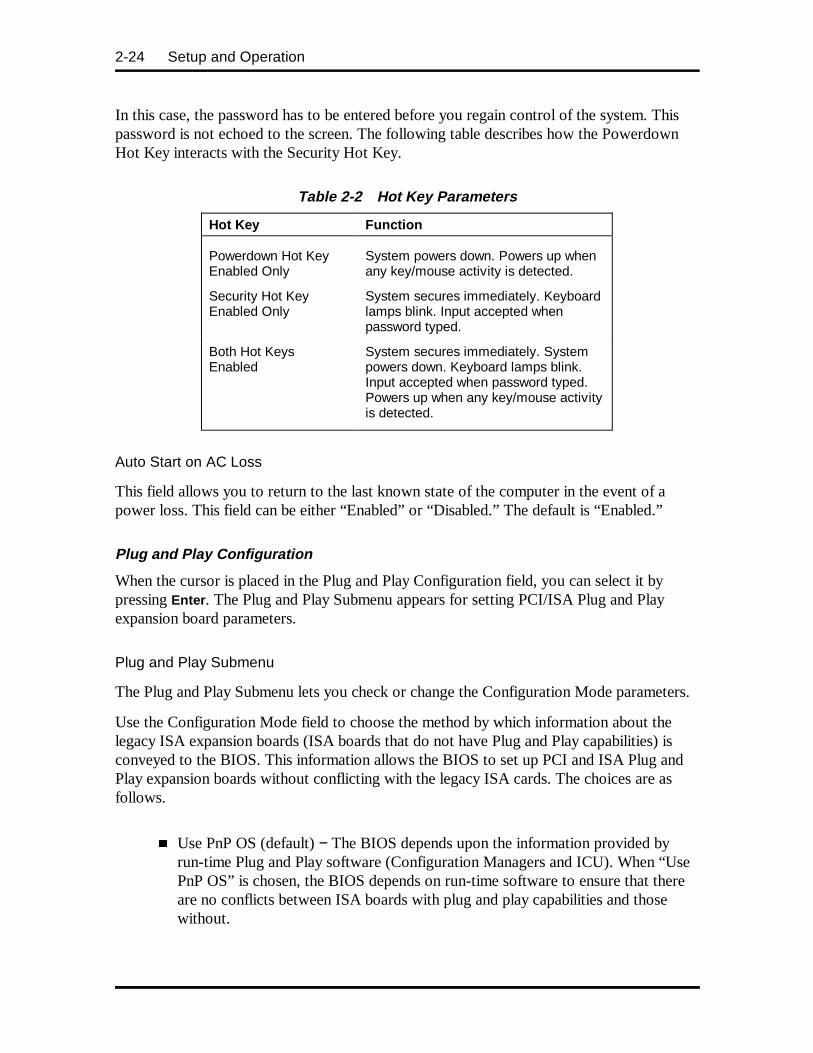
2-24 Setup and Operation
In this case, the password has to be entered before you regain control of the system. Thispassword is not echoed to the screen. The following table describes how the PowerdownHot Key interacts with the Security Hot Key.
Table 2-2 Hot Key Parameters
Hot Key Function
Powerdown Hot KeyEnabled Only
System powers down. Powers up whenany key/mouse activity is detected.
Security Hot KeyEnabled Only
System secures immediately. Keyboardlamps blink. Input accepted whenpassword typed.
Both Hot KeysEnabled
System secures immediately. Systempowers down. Keyboard lamps blink.Input accepted when password typed.Powers up when any key/mouse activityis detected.
Auto Start on AC Loss
This field allows you to return to the last known state of the computer in the event of apower loss. This field can be either “Enabled” or “Disabled.” The default is “Enabled.”
Plug and Play Configuration
When the cursor is placed in the Plug and Play Configuration field, you can select it bypressing Enter . The Plug and Play Submenu appears for setting PCI/ISA Plug and Playexpansion board parameters.
Plug and Play Submenu
The Plug and Play Submenu lets you check or change the Configuration Mode parameters.
Use the Configuration Mode field to choose the method by which information about thelegacy ISA expansion boards (ISA boards that do not have Plug and Play capabilities) isconveyed to the BIOS. This information allows the BIOS to set up PCI and ISA Plug andPlay expansion boards without conflicting with the legacy ISA cards. The choices are asfollows.
� Use PnP OS (default) − The BIOS depends upon the information provided byrun-time Plug and Play software (Configuration Managers and ICU). When “UsePnP OS” is chosen, the BIOS depends on run-time software to ensure that thereare no conflicts between ISA boards with plug and play capabilities and thosewithout.

Setup and Operation 2-25
� Use BIOS Setup − The BIOS depends upon the information provided by you inthe following fields to prevent conflicts between the Plug and Play and ISA legacyboards. You should not install and use run-time Plug and Play software such asConfiguration Managers and the ISA Configuration Utility (ICU).
Boot with PnP OS
The Boot with PnP OS field enables the system to boot with an operating system capable ofmanaging Plug and Play add-in cards. The choices are as follows.
� Disabled
� Other
� Windows 95 or Windows NT 4.0 (default)
NOTE: The following three fields (ISA SharedMemory Size, ISA Shared Memory Address, andIRQ 5,9,10,11 Available) display only ifConfiguration Mode is set to “Use BIOS Setup”rather than the “Use PnP OS.”
ISA Shared Memory Size
The ISA Shared Memory Size field is used to set a block of system memory that will not beshadowed. (Shadowing is a technique that copies a block of memory from an address in theexpansion board’s ROM to the same address in the system memory to allow faster access tothe code and achieve higher performance.)
If “Disabled,” all upper memory is shadowed and the ISA Shared Memory Base Addressfield is not displayed. This field provides the following choices.
When a value other than “Disabled” is selected, a block is unshadowed and the ISA SharedMemory Base Address field appears.
� Disabled (default)
� 16 KB
� 32 KB
� 48 KB
� 64 KB
� 80 KB
� 96 KB.
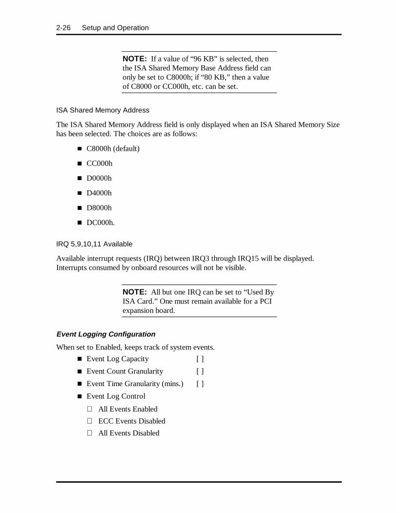
2-26 Setup and Operation
NOTE: If a value of “96 KB” is selected, thenthe ISA Shared Memory Base Address field canonly be set to C8000h; if “80 KB,” then a valueof C8000 or CC000h, etc. can be set.
ISA Shared Memory Address
The ISA Shared Memory Address field is only displayed when an ISA Shared Memory Sizehas been selected. The choices are as follows:
� C8000h (default)
� CC000h
� D0000h
� D4000h
� D8000h
� DC000h.
IRQ 5,9,10,11 Available
Available interrupt requests (IRQ) between IRQ3 through IRQ15 will be displayed.Interrupts consumed by onboard resources will not be visible.
NOTE: All but one IRQ can be set to “Used ByISA Card.” One must remain available for a PCIexpansion board.
Event Logging Configuration
When set to Enabled, keeps track of system events.
� Event Log Capacity [ ]
� Event Count Granularity [ ]
� Event Time Granularity (mins.) [ ]
� Event Log Control
All Events Enabled
ECC Events Disabled
All Events Disabled
Setup and Operation 2-27
� Clear Event Log
Keep
On Next Boot
� Mark Existing Events as Read
Do Not Mark
Mark
� Critical Events in Log:
Single Bit ECC Events
Multiple Bit ECC Events
Parity Error Events
PreBoot Events
If Critical Events in Log items are entered, the following is displayed:
� Parity Error Events [count]If Enter is pressed, the following appear:
Date of Last Occurrence [DATE]
Time of Last Occurrence [TIME]
Total Count of Events/Errors [COUNT]
Memory Bank with Errors [BANK]
Security Menu
There are two types of passwords available: “User Password” and “AdministrativePassword.” The user passwords can be used to access the Setup Utility, the keyboard uponinitial boot, and the keyboard when used in conjunction with the Security Hot Key. TheAdministrative Password is used to control access to the Setup Utility. The following tabledescribes the interaction between these passwords.
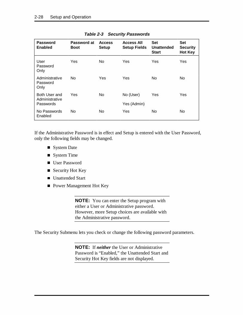
2-28 Setup and Operation
Table 2-3 Security Passwords
PasswordEnabled
Password atBoot
AccessSetup
Access AllSetup Fields
SetUnattendedStart
SetSecurityHot Key
UserPasswordOnly
Yes No Yes Yes Yes
AdministrativePasswordOnly
No Yes Yes No No
Both User andAdministrativePasswords
Yes No No (User)
Yes (Admin)
Yes Yes
No PasswordsEnabled
No No Yes No No
If the Administrative Password is in effect and Setup is entered with the User Password,only the following fields may be changed.
� System Date
� System Time
� User Password
� Security Hot Key
� Unattended Start
� Power Management Hot Key
NOTE: You can enter the Setup program witheither a User or Administrative password.However, more Setup choices are available withthe Administrative password.
The Security Submenu lets you check or change the following password parameters.
NOTE: If neither the User or AdministrativePassword is “Enabled,” the Unattended Start andSecurity Hot Key fields are not displayed.
Setup and Operation 2-29
� Enter Password
This field allows you to enable a user level password during POST and to enterSetup. When both the “User Password is” and “Administrative Password is” are“Enabled,” only the Administrative Password gives you full access to all Setupfields. This field can be either “Enabled” or “Disabled.” The default is “Disabled.”
� Set Administrative Password
This field allows you to enable an administrative level password during POST andto enter Setup. When both the “User Password is” and “Administrative Passwordis” are “Enabled,” only the Administrative Password gives you full access to allSetup fields. This field can be either “Enabled” or “Disabled.” The default is“Disabled.”
When the Administrative password is set, you can configure User Privilege levelsfor limited access, no access, view only, or full access.
Enter Password and Set Administrative Password
Enable either or both the User or Administrative Passwords and a dialog box appears withthe following prompts. Passwords are not case-sensitive.
To set a password, type the password and press Enter . Reenter the password and pressEnter .
Enter new password: [ ]Confirm new password: [ ]
If there is already a User or Administrative Password, then a dialog box with the followingprompts appears.
Enter current password: [ ]Enter new password: [ ]Confirm new password: [ ]
When both User and Administrative Passwords are set, the Clear User Password fieldappears. Press Enter to clear a User Password and display a Confirmation dialog box.
Unattended Start
The Unattended Start field controls the point at which the User Password is required. TheUnattended Start field can only be set if a User Password is in effect.
Disabled (default) − prompts the user for the password before the system boots. The textstring prompt “Enter Password (1)” is displayed.

2-30 Setup and Operation
Enabled − completely boots the system (including running CONFIG.SYS andAUTOEXEC.BAT), then locks the keyboard. The User Password must be entered tounlock it. The BIOS does not provide any prompt string.
Security Hot Key (CTRL-ALT-)
The Security Hot Key field is used to lock the keyboard when you step away from thesystem. When you press CTRL – ALT – alpha-numeric key (the alpha-numeric key isdefined by the user) the system enters secure mode (locks the keyboard).
When this Hot Key combination is entered, the Num Lock, Caps Lock, and Scroll Locklamps on the keyboard will flash in sequence, indicating that the system is in secure mode.
NOTE: If Power Management is enabled andthe computer enters sleep mode (through thePower Management Hot Key, Unattended Start,or the Suspend button) while the Administrativeand User passwords are set, the computer can bereturned from sleep mode only by entering theUser password. Entering the Administrativepassword, moving the mouse, or randomkeyboard input have no effect.
Exit Menu
Selecting “Exit” from the menu bar displays the following exit options. Click on a topic fora description of the Exit Menu options. Note that Esc does not exit this menu. You mustselect one of the items from the menu or menu bar to exit.
� Exit Saving Changes
� Exit Discarding Changes
� Load Setup Defaults
� Discard Changes.
Exit Saving Changes
After making your selections on the Setup menus, always select “Exit Saving Changes” tomake them operative.
When “Exit Saving Changes” has been selected, the program displays this message:
Exit Saving Changes?Press Enter to ContinuePress ESC to Abort

Setup and Operation 2-31
To save the changes and exit Setup, press Enter . Press Esc to return to the Exit submenuwithout saving your changes.
Exit Discarding Changes
Use this option to exit Setup without recording any changes you may have made. After youselect “Exit Discarding Changes, the program displays this message:
Exit Discarding Changes?Press Enter to ContinuePress ESC to Abort
To exit Setup without saving the changes, press Enter . To save your changes, press Esc toreturn to the Exit submenu.
Load Setup Defaults
To load all the default Setup values in the Setup menus, select “Load Setup Defaults” fromthe Exit Submenu. Reloading the defaults does not affect any set passwords. The programdisplays this message:
Load Setup Defaults?Press Enter to ContinuePress ESC to Abort
To load the defaults shipped with the system, press Enter . Press Esc to return to the Exitsubmenu without affecting your changes.
Discard Changes
To undo any changes you have made in the Setup menus since Setup was last saved, select“Discard Changes.” The program displays this message:
Discard Changes?Press Enter to ContinuePress ESC to Abort
To reset all changes made in the current session of Setup, press Enter . Press Esc to returnto the Exit submenu without affecting your changes.
FLASH UTILITY
The system BIOS resides on a flash ROM in the system. The flash ROM can be updatedshould it ever become necessary. This feature allows the ROM BIOS chip to be flashed witha new BIOS code through software, rather than replacing the chip.
2-32 Setup and Operation
Performing an update is done with a BIOS flash diskette. The diskette, which contains thelatest version of the BIOS code, can be obtained from NECCSD Technologies or, if amodem is available, the latest BIOS can be downloaded from NECCSD’s Bulletin BoardService (BBS).
If a modem is available, use the following procedure to access the BBS for the latestversion of the BIOS Update utility. How to flash the BIOS with a flash diskette is describedfollowing the BBS access procedure.
See the following subsection, “NEC Bulletin Board Service,” for information about usingthe bulletin board (available in the U.S. and Canada).
NECCSD Bulletin Board Service
If you have access to a modem, the NECCSD Bulletin Board Service (BBS) can be used toprovides the latest BIOS information. The BBS allows you to download files (ICU, videodrivers, printer drivers, BIOS updates, etc.). The BBS can also be accessed through theCompuServe online service.
Log onto the BBS as follows.
If you have access to a modem, the NECCSD Bulletin Board Service (BBS) can be used toprovide you with the latest information on hardware and software. The BBS allows you todownload files (video drivers, printer drivers, BIOS updates, etc.) for system enhancementsand upgrades.
The BBS can also be accessed through the CompuServe online service.
Log onto the BBS as follows.
1. From the Windows desktop, click the Start button.
2. Point to Programs. Point to Accessories and then click HyperTerminal .
3. Double click the Hypertrm.exe icon. The HyperTerminal program appears.
4. Follow the instructions on the screen to set up the modem. Click theHyperTerminal Help button for information about dialing the phone number.
If you need to check communications settings, check that the settings match thefollowing BBS parameters.
� Baud rate: select any baud rate that matches the modem
� Parity: none
� Data bits: 8
� Stop bits: 1
� Flow control: Xon/Xoff (select Hardware if using 14.4 bps or higher)
Setup and Operation 2-33
5. Following the HyperTerminal instructions, enter the BBS phone number(508-635-4706). Your business phone system and/or location might require a9 1 or 1 prefix.
NOTE: The first time that you use the BBS,you will be requested to provide information fora new user questionnaire.
6. Press Enter twice
7. Enter your first name, last name, and password. Press Enter after each.
8. Follow the screen prompts until the Main Menu is displayed.
9. At the Main Menu, select J to join a conference. Select Conference 1 for thedesktop conference.
10. From the Main Menu, press F and Enter for the File menu.
11. At the File menu, select F for a list of downloadable files. Follow the prompts toselect a file for downloading.
CAUTION: Executable files automaticallyformat the diskette when you download filesfrom the BBS. Formatting destroys any data onthe diskette. Before you download files from theBBS, check that you do not have information onthe diskette that you need.
After you complete downloading the file, log off the BBS as follows.
1. Press Enter (to continue)
2. Press G (command for Goodbye/Hangup).
3. Press Enter .
NOTE: First time users must answer a new userquestionnaire.
Flash Utility
Check the NECCSD Bulletin Board Service (BBS) for available updates to the systemBIOS. You can obtain information to update the system with the latest BIOS version fromthe NECCSD Bulletin Board Service.

2-34 Setup and Operation
Update the BIOS from the BIOS flash diskette as follows.
1. Write down the Setup parameters currently set on the system.
2. Turn off the system.
3. Insert the flash diskette in drive A, and turn on the system.
4. When the flash upgrade menu appears, choose “Update Flash Memory Area froma file.”
5. When the menu asks you to enter a path/filename, use the arrow keys to select the“.bio” file, and press Enter .
6. The utility asks for a confirmation that you want to load the new flash data intomemory. Select “Continue with Programming.”
7. After the upgrade completes, remove the upgrade disk.
8. Reboot the system and start the Setup program. Press <F5> to reset the BIOSdefaults. Then, use the copy of the Setup selections you made at the beginning ofthis procedure to set the options.
See “NECCSD Bulletin Board Service” in the previous subsection for information aboutusing the bulletin board (available in the U.S. and Canada).
SCSISelect UTILITY
Select the SCSISelect utility at boot up. Press Ctrl-A as soon as you see the SCSI utilityinformation on the screen. When the BIOS information appears, you have gone past thewindow and must reboot.
The SCSISelect utility sets termination. In addition, from the SCSISelect utility you canperform the following:
� format a new SCSI drive
� configure the host adapter
� set a new SCSI ID.
To set a new SCSI ID, select the SCSI Device Configuration menu. With the arrow keys,select Send Start Unit Command. Change the unit ID number from no to yes.
The ID for the SCSI adapter board is 7 and the installed SCSI hard drive is 0.
LANDESK CLIENT MANAGER
LANDesk Client Manager is provided with the PowerMate Professional Series system.

Setup and Operation 2-35
LANDesk Client Manager Setup
Use the following procedure to setup the LANDesk Client Manager software:
1. Click the Start button on the taskbar.
2. Point to “Programs” to open the Programs menu.
3. Point to “LanDesk Client Manager.”
4. In the submenu, point and click on “LanDesk 3.0 Setup.”
5. Follow the instructions in the Setup program.
Features
With Client Manager you can do the following:
� review system inventory
� view DMI-compliant component information
� back up and restore system configuration files
� troubleshoot
� receive notice of system events
� transfer files to and from client workstations
� remotely reboot client workstations.
There are two main components of Client Manager: PC health indicator and inventory.
PC Health Indicator
PC Health Indicator consists of three parts:
� Managing workstations
� PC Health meter
� PC health description.
Managing Workstations
Client Manager sets up a connection to all the workstations running on the network toallow the administrator to monitor the functions of each workstation.
The monitoring is in real time so that if an unhealthy workstation is fixed, you can refreshthe screen to view the new correct PC health. You can also set the monitor to report onlyunhealthy workstations.

2-36 Setup and Operation
PC Health Meter
The PC Health meter is a traffic signal that provides the following visual indicators ofworkstation health:
� A red light means that a critical system event has occurred. You are required tofix the problem immediately.
� A yellow light or noncritical system event requires that you monitor the situation.It may be a problem that could get worse and become a critical event.
� A green light means everything is working fine with the system.
PC Health Description
The description of PC health is determined by monitoring various system components forthreshold levels. Some of the components that are monitored are as follows:
� drive space
� prediction of hard drive failure
� free virtual memory
� temperatures
� power supplies
� fans
� chassis opened
� GDI
� noncritical boot failure
� boot virus detection.
Once a threshold level has been passed on a workstation, you can request notification of theproblem and have it written into a log file.
Setup and Operation 2-37
Inventory
Client Manager Inventory views the hardware and software components of the workstation.The inventory consists of the following categories:
� workstation summary
� basic hardware
� drives
� memory
� audio
� keyboard/mouse
� video
� system resources
� I/O ports
� operating system
� network
� applications
� system files
� user information.
You can also view the current system configuration, edit user information, and create orrestore file snapshots.
Using DMI
As a part of the LANDesk Client Manager, the Desktop Management Interface (DMI) isthe standard interface used to manage system components on the computer. Examples ofsystem components are network interface cards, printers, and software applications. Systemcomponents provide a Management Information Format (MIF) file to be DMI-compliant.The information file describes component attributes that can be managed.
Client Manager can be used to “get” attribute information on system components. It canalso be used to “set” attribute values in real time.

2-38 Setup and Operation
NEC MagicEye Technology
The PowerMate Professional Series computer has a chip mounted on the system board thatsupports the NEC MagicEye™ Technology. The purpose of this technology is to providemany new and advanced real-time monitoring capabilities used by DMI. The NECMagicEye Technology provides the following features:
� an integrated temperature sensor with configurable interrupt generation based onupper and lower temperature limits
� a power supply monitor with configurable interrupt generation based on high andlow voltage limits
� chassis intrusion detection with interrupt generation capabilities.
To take advantage of these advanced capabilities, DMI has expanded its interface in thefollowing areas.
� MagicEye interrupts may be enabled or disabled.
� High and low limits can be set and are displayed for temperature and powersupply voltages.
� Current readings are displayed for temperature, power supply voltages, andchassis state.
� MagicEye interrupts can be detected when “out of range” condition occurs. Userprompts are displayed to alert the user to a potentially harmful condition.
NOTE: To enable/disable LANDesk features(such as the chassis intrusion alert message),refer to the online LANDesk Client ManagerHelp file.
VIDEO DRIVERS
Video drivers let you take advantage of the computer’s integrated video hardware andextended graphics modes. The system ships with Matrox or Number Nine Imagine videodrivers for Windows 95 or Windows NT 4.0 loaded on the hard disk.
The default video mode is 800 by 600 pixels with 256 colors. You can change the defaultvideo resolution in Windows Setup. You can also change the video resolution and othervideo features such as refresh rates in Windows. See “Changing Display Properties,” in thefollowing subsection.
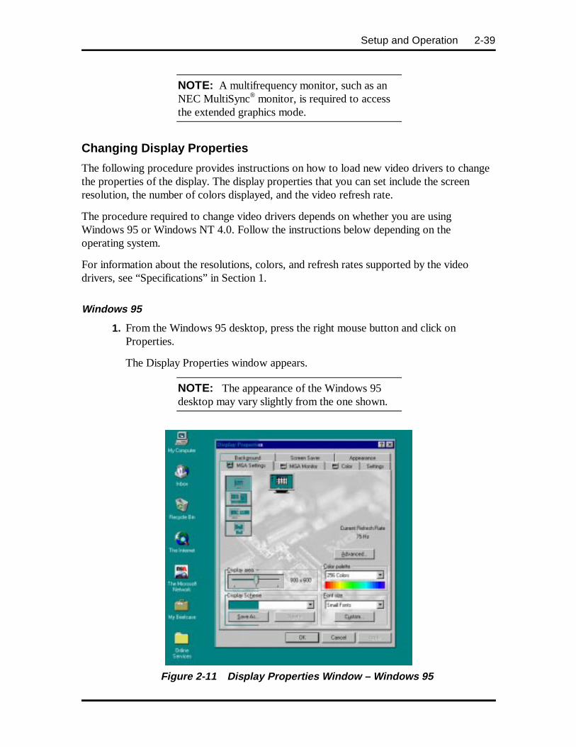
Setup and Operation 2-39
NOTE: A multifrequency monitor, such as anNEC MultiSync® monitor, is required to accessthe extended graphics mode.
Changing Display Properties
The following procedure provides instructions on how to load new video drivers to changethe properties of the display. The display properties that you can set include the screenresolution, the number of colors displayed, and the video refresh rate.
The procedure required to change video drivers depends on whether you are usingWindows 95 or Windows NT 4.0. Follow the instructions below depending on theoperating system.
For information about the resolutions, colors, and refresh rates supported by the videodrivers, see “Specifications” in Section 1.
Windows 95
1. From the Windows 95 desktop, press the right mouse button and click onProperties.
The Display Properties window appears.
NOTE: The appearance of the Windows 95desktop may vary slightly from the one shown.
Figure 2-11 Display Properties Window – Windows 95
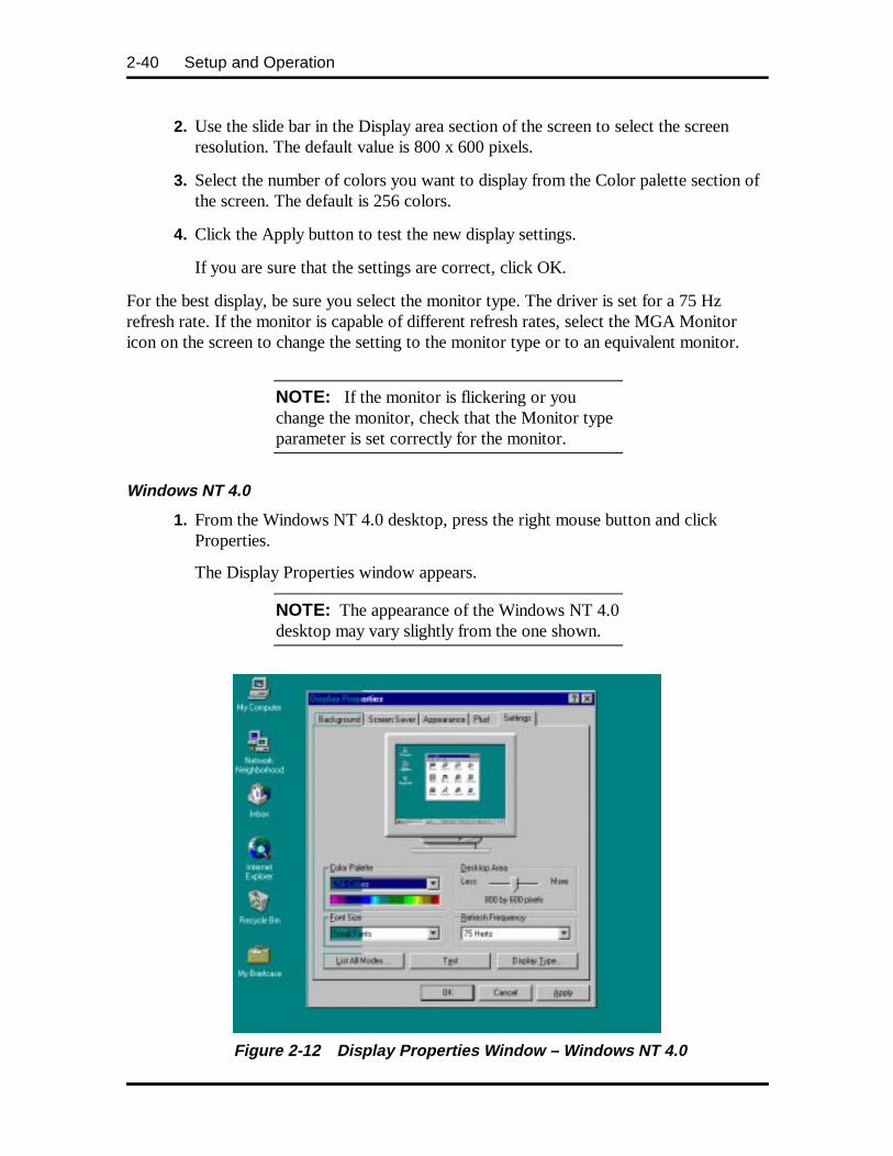
2-40 Setup and Operation
2. Use the slide bar in the Display area section of the screen to select the screenresolution. The default value is 800 x 600 pixels.
3. Select the number of colors you want to display from the Color palette section ofthe screen. The default is 256 colors.
4. Click the Apply button to test the new display settings.
If you are sure that the settings are correct, click OK.
For the best display, be sure you select the monitor type. The driver is set for a 75 Hzrefresh rate. If the monitor is capable of different refresh rates, select the MGA Monitoricon on the screen to change the setting to the monitor type or to an equivalent monitor.
NOTE: If the monitor is flickering or youchange the monitor, check that the Monitor typeparameter is set correctly for the monitor.
Windows NT 4.0
1. From the Windows NT 4.0 desktop, press the right mouse button and clickProperties.
The Display Properties window appears.
NOTE: The appearance of the Windows NT 4.0desktop may vary slightly from the one shown.
Figure 2-12 Display Properties Window – Windows NT 4.0
Setup and Operation 2-41
2. Use the slide bar in the Display Area section of the screen to select the screenresolution. The default value is 800 x 600 pixels.
3. Select the number of colors you want to display from the Color Palette section ofthe screen. The default is 256 colors.
Alternatively, click on List All Modes. You get a list of all the modes available forthe video board.
4. Click the Apply button to test the new display settings.
If you are sure that the settings are correct, click OK.
CD RESTORE
Windows 95 systems ship with a CD Restore compact disc (CD) included. The CD Restorefiles let you restore all the system software files to their original factory-installed state.
The following subsections contain information on these procedures:
� selecting CD Restore options
� restoring individual files
� recovering the system.
Selecting CD Restore Options
The following guidelines should help you decide which CD Restore procedures you shoulduse.
Restore Individual Files
This option lets you select the files and directories you want restored from the CD Restorecompact disc. Use this option to:
� restore only a few files
� control which files and directories are restored to their factory state.
You can use this option for restoring AUTOEXEC, CONFIG, and INI files.
This procedure runs in Windows 95. You’ll need to boot the system from the hard disk,enter Windows, and insert the CD into the CD-ROM reader.
System Recovery
Use this option as a last resort when the preinstalled software becomes unusable or youcan’t reboot from the hard disk. This option requires booting from the CD.
2-42 Setup and Operation
The System Recovery option
� provides a full system recovery. This means you’ll be able to restore the system toits original factory-shipped state.
� reformats hard drive C and erases all information on the disk.
� then restores files on drive C from the CD Restore disc.
Before System Recovery, you will need to
� back up all the data files to an external storage device (diskette, tape, or zipcartridge drive). System Recovery removes all data.
� be prepared with software installation diskettes of any software applicationprograms that you installed yourself.
After System Recovery, you will need to
� restore to the hard disk all the data files that you backed up before SystemRecovery.
� reinstall any software application program that you installed yourself.
The following sections describe each of these options. If the preinstalled software becomesunusable, see “Recovery Options” later in this section.
Restoring Individual Files
Here’s how to restore individual files to the hard disk:
1. With system power on, insert the CD Restore disc into the CD-ROM reader.
2. On the Windows 95 desktop, double click My Computer .
3. Double click the CD-ROM reader (F:) icon. The NEC System Restore screenappears.
4. At the System Restore screen, click OK to restore individual files. A licenseagreement appears.
5. Read the license agreement and click I agree to continue. The Restore IndividualFiles screen appears. The screen is divided into two areas:
� 1 Select files to restore — This is where you select the specific files you want to restore.
� 2 Check list of files to be restored — This area lets you check the files you selected for restoration.

Setup and Operation 2-43
The following sections explain how to use the Restore Individual Files screen. Complete allsections to restore the files.
Selecting Files
Under “Select files to restore,” select the files as follows:
1. From the left dialog box, highlight the directory that contains the files you want torestore.
2. From the right dialog box, highlight the files you want to use:
� To restore all of the files listed, click “Select all of the above.” This highlightsand selects all the files listed.
� To restore only some of the files listed, click the file you want and highlight it.
3. Once the files are highlighted, select the appropriate button under the list. Thebuttons include:
� Add selected files to list — click this button to add the selected files to the listof files to be restored.
� Clear all selections — click this button to deselect the files listed.
4. Repeat steps 1 through 3 to select files from other directories. Continue until allthe files you want restored are selected.
Checking Selected Files
To continue the restoration process, check the files to be restored as follows.
1. Look at the list of files in the “Check list of files to be restored” area of thescreen.
2. If you need to add any files to the list, go back to the preceding section and repeatthose steps.
3. If you need to remove any files from the list, do so as follows.
� To remove any selected files, highlight the filename and click “Delete item inlist.” This method lets you remove one item at a time.
� To remove the entire list, click “Clear list.”
Once the list is set, continue to the next section.
2-44 Setup and Operation
Restoring the Files
Complete the restoration process as follows.
1. In the “Restore the files from the CD” area of the screen, locate the two options:
� Restore the files listed — this option lets you proceed with the restoration andcontinue to the next step. Go to the next step to complete the restoration.
� Cancel — click this option to cancel the restoration. This returns you to theNEC System Restore menu.
2. To proceed with the restoration, click “Restore the files listed.” When therestoration is completed, a file restore message appears.
3. Click OK.
4. If you replaced any Windows system files, exit Windows and restart the system.
Recovering the System
If the preinstalled software becomes unusable or you can’t reboot from the hard disk, youcan still restore the system to its original shipping configuration.
System Recovery erases and resets the hard disk completely before reinstalling the files.
CAUTION: If you are doing a Full SystemRecovery, ALL files on the hard drive will bedeleted and replaced by the factory installed files.
You will
• lose data
• need to reinstall any software you installedyourself.
Full System Recovery should only be used if thepreinstalled software is unusable. If you areunsure about using this procedure, call theNECCSD Technical Support Center (TSC). TSCrepresentatives will help you determine if this isyour situation. See Chapter 4 for the technicalsupport telephone number.
The System Recovery requires booting from the CD Restore disc. Here is the procedure tostart the recovery process. Follow it carefully.
Setup and Operation 2-45
1. With system power on, insert the CD Restore disc into the CD-ROM reader.
2. Turn system power off.
3. Turn on system power. The System Recovery screen provides information aboutthe restore process. Read this information.
You can choose one of the following two options:
� Continue — Proceeds with the recovery program.
� Quit — Exits the recovery program back to the operating system.
4. Click Continue to proceed with the System Recovery. A license agreementappears.
5. Read the license agreement and click I agree to continue. The Start SystemRecovery screen appears.
6. The Start System Recovery screen states that all the files will be removed and thatthis process is irreversible. At the “Are you sure?” prompt, click Yes to continue.
The system files are restored and the System Recovery Completed screen appears.Remove the CD and restart the computer.
NOTE: Information on restoring softwaredrivers and Windows NT 4.0 applications may befound in the following subsections.
WINDOWS NT 4.0 APPLICATION CD INSTALLATION INSTRUCTIONS
Use these instructions with the PowerMate Professional Series Windows NT 4.0Application CD to install the following applications on PowerMate Professional Seriescomputers:
� McAfee VirusScan version 2.5.3
� LANDesk Client Manager 3.0 version 1.1e.
McAfee VirusScan Installation
Use the following procedures to install McAfee VirusScan using the Windows NTApplication CD.
1. Insert the PowerMate Professional Series Windows NT Application CD into theCD-ROM reader.
2-46 Setup and Operation
2. From the Windows NT desktop, double click the following icons in succession:My Computer , the CD-ROM reader icon, Mcafee , and Disk1 .
3. Double click the Setup icon. The McAfee VirusScan NT v2.5.3 (Licensed) -Setup screen appears. The Welcome to Setup window appears on the screen.
4. Click Next . The Setup Type window appears displaying the default pathC:\Program Files\McAfee\VirusScan NT .
5. Click Next to accept the path. The Service Account Usage window appears.
6. Click Next . The Service Account Information window appears.
The Service Account Information window allows an Administrator to establishpassword protection on the system.
7. Choose a password option:
� To establish password protection, type the password in both password fields,click Next , and click Next again.
� To bypass password protection, click Skip .
The What’s New In VirusScan NT window appears. It provides access to thelatest information about the VirusScan.
8. Choose whether to bring up the What’s New In VirusScan NT window:
� Click Yes to bring up the window. Close the window to continue with theinstallation.
� Click No to bypass the window.
9. Click Finish when the “Installation complete, finalizing configurations” windowappears. This restarts the computer.
LANDesk Client Manager Installation
The following procedures describe how to install LANDesk Client Manager (LDCM) withthe Windows NT Application CD. LANDesk Client Manager may be installed to run inlocal (client) or administrator mode.
Local Mode
Load the local (client) version of LANDesk Client Manager into a system with the
Windows NT operating system using the following procedures:
1. Insert the PowerMate Professional Series Windows NT Application CD into theCD-ROM reader.
Setup and Operation 2-47
2. From the Windows NT desktop, double click the following icons in succession:My Computer , the icon for the CD-ROM reader, Landesk , and Local .
3. Double click the Setup icon. The LANDesk Client Manager Setup forWindows NT screen appears. The Welcome window appears over the screen.
4. Click Next . The Autoload Configuration Selection window appears displaying thesystem type PowerMate Professional .
5. Click Next to accept the system type. The Choose Destination Location windowappears with C:\DMI as the default directory for the installation.
6. Click Next to accept the directory. The Select Program Folder appears, displayingthe default folder LANDesk Client Manager .
7. Click Next . The LDCM Setup Complete window appears. Verify that the optionYes, I want to restart my computer now is selected.
8. Remove all disks from the system.
9. Click Finish to restart the computer.
Administrator Mode
Load the administrative version of LANDesk Client Manager into a system with the
Windows NT operating system using the following procedure:
1. Insert the PowerMate Professional Series Windows NT Application CD into theCD-ROM reader.
2. From the Windows NT desktop, double click the following icons in succession:My Computer , the icon for the CD-ROM reader, Landesk , and Admin .
3. Double click the Setup icon. The LANDesk Client Manager Setup for WindowsNT screen appears. The Welcome window appears on the screen.
4. Click Next . The Drive Selection window appears with C:\DMI as the defaultdirectory for the installation.
5. Click Next to accept the directory. The Documentation Install Options windowappears. Highlight the documentation options appropriate for the system.
6. Click Next . The Select Program Folder appears, displaying the default folderLANDesk Client Manager .
7. Click Next . The LDCM Setup Complete window appears. Verify that the optionYes, I want to restart my computer now is selected.
8. Remove all disks from the system.
2-48 Setup and Operation
9. Click Finish to restart the computer. The Admin Install Information window mayappear before the system restarts. If it does, click OK to acknowledge thatACROREAD.EXE must be run to install Adobe Acrobat Reader. This isnecessary to access some of the online documentation.
DRIVER CD INSTALLATION INSTRUCTIONS
Use these instructions with the PowerMate Professional Series Driver CD to install driverson PowerMate Professional Series computers.
The following drivers must be installed if the operating system is upgraded:
� NEC 16X CD-ROM Drivers dated 5/8/96 for the Windows 95 operating system
� PIIX3 IDE Drivers for Windows 95
� PIIX3 IDE Drivers for the Windows NT 4.0 operating system.
Drivers for video and sound are also on the Driver CD. Installation of these drivers isoptional:
� Matrox Mystique Video Drivers version 4.03.00.3170 for Windows 95
� Matrox Mystique Video Drivers version 2.30.07 for Windows NT
� Yamaha Audio Drivers version 3.02i for Windows 95
� Yamaha Audio Drivers version 3.03 for Windows NT
� Number Nine Imagine 128 Series 2 Video Card Drivers version 4.102.13.01.
NOTE: Some procedures for the Windows 95operating system must be performed before aWindows 95 operating system upgrade isperformed. Review the procedures beforeperforming the upgrade.
Driver Installation Guidelines
Read through these guidelines before installing drivers. They address the conditions underwhich drivers should be installed.
Guidelines for Windows 95 Installations
Follow these guidelines when preparing the system and installing drivers:
� Have the Windows 95 CD-ROM installation disc ready.
Setup and Operation 2-49
� Have ready an MS-DOS bootable diskette containing a config.sys file and anautoexec.bat file.
� Perform the steps in the “Preparation” section before upgrading to the Windows95 operating system.
� Install the NEC 16X CD-ROM drivers before installing the IDE, video, or audiodrivers.
� Install the PIIX3 IDE Drivers before installing the video or audio drivers.
Guidelines for Windows NT Installations
Follow these guidelines when preparing the system and installing drivers:
� Have a spare diskette ready.
� Bear in mind that the system will not be able to play audio CDs orCD-I formatted CDs after the PIIX3 drivers are installed.
Driver Installation For the Windows 95 Operating System
The following procedures describe how to load the drivers for the Windows 95 operatingsystem.
NOTE: Perform the steps in the “Preparation”section and install the PIIX3 IDE Drivers beforeinstalling the video or audio drivers.
Preparation
Perform the following procedure before installing the Windows 95 operating system andbefore installing the drivers.
1. Insert an MS-DOS bootable diskette into drive A.
2. Copy a config.sys and an autoexec.bat file from the system to the diskette.
3. Add the following line to the config.sys file:
device=nec_ide. sys /D:MTMIDE01
4. Add the following line to the autoexec.bat file:
MSCDEX.EXE /D:MTMIDE01 /M:10
5. Insert the PowerMate Professional Series Driver CD into the CD-ROM reader.

2-50 Setup and Operation
6. From the Windows 95 desktop, click Start , point to Programs , and clickWindows Explorer .
7. In the Exploring menu, click View , point to Options , and select Show all files .Click OK.
8. Select the CD-ROM drive and copy the contents of the doscdrom folder to thediskette.
9. Double click the Win95 folder on the CD-ROM. Copy the piix3ide folder to thediskette.
NEC 16X CD-ROM Drivers
Load the NEC 16X CD-ROM Drivers into a system equipped with Windows 95 asfollows.
NOTE: Do not proceed until you have followedthe procedure in “Preparation” above.
1. Modify the system’s config.sys and autoexec.bat files to add CD-ROM drivers.See the directions in the MS-DOS documentation.
2. Reboot the system.
PIIX3 IDE Drivers
Load the PIIX3 IDE Drivers into a system with the Windows 95 operating system asfollows.
NOTE: Do not proceed until you haveperformed the procedures in “Preparation” and“NEC 16X CD-ROM Drivers” above.
1. If necessary, reinsert the diskette used during the preparation procedure intodrive A.
2. From the Windows 95 desktop, double click the following icons: My Computer ,3 1/2 Floppy (A:) , and piix3ide . Double click the setup icon in the piix3idewindow.
3. Click Next in the 82371SB IDE Setup window when notified that the Mshdc.inffile is being backed up and modified.
4. Click Next to confirm the process.
Setup and Operation 2-51
5. Read all the directions that appear in the 371SBIDE HELP window. Then followthe directions with this one exception: remove the Standard IDE DeviceController before removing the PCI IDE Controller. Take care not to restart thesystem from the Devices Manager window.
NOTE: Remove the Standard IDE DeviceController before removing the Primary PCI IDEController.
6. Restart the system manually, according to the last step in the 371SBIDE HELPwindow. After the system restarts, the New Hardware Found window appears.
7. Click OK. The System Settings Change window appears.
8. Click Yes to restart the system and to complete the installation process.
Matrox Mystique Video Drivers
Load the Matrox Mystique Video Drivers into a system with Windows 95 as follows.
NOTE: Perform the procedures in“Preparation,” “NEC 16X CD-ROM Drivers,”and “PIIX3 IDE Drivers” before installing videodrivers.
Do not install video drivers from Windows 95while in Safe Mode.
1. Insert the PowerMate Professional Series Driver CD into the CD-ROM reader.
2. From the Windows 95 desktop, click Start on the taskbar, point to Programs ,and click Windows Explorer .
3. From the Explorer window, double click the CD-ROM drive icon.
4. Access the folder containing the video drivers by clicking the following folders insuccession: Win95 , Video , Matrox , and Disk1 . The Disk1 window opens.
5. Double click Setup to bring up the Language window.
6. Select English and click Next . The MGA PowerDesk Setup screen appears, andthe Choose destination location box comes up in the screen. The default path inthe box should be C:\Program Files\Matrox MGA PowerDesk .
7. Click Next to bring up the Program selection box. All programs are checked bydefault.
2-52 Setup and Operation
8. Click Next . The Finally window appears noting that the electronicdocumentation has been installed in the PowerDesk folder.
9. Click OK to bring up the Systems Settings Change window.
10. Click Yes to restart the computer.
Yamaha Audio Drivers
Load the Yamaha Audio Drivers into a system with the Windows 95 operating system asfollows.
NOTE: Perform the procedures in“Preparation,” “NEC 16X CD-ROM Drivers,”and “PIIX3 IDE Drivers” before installing audiodrivers.
1. Insert the PowerMate Professional Series Driver CD into the CD-ROM reader.
2. From the Windows 95 desktop, double click the My Computer icon, doubleclick the Control Panel icon, and double click the System icon to bring up theSystem Properties window.
3. Click the Device Manager tab. In the Device Manager display, click OtherDevices and highlight OPL3-SA2 Sound System .
4. Click Properties . The OPL3-SA2 Snd System Properties window appears.
5. Click the Driver tab. In the Driver display, click Change Driver to bring up theSelect Hardware Type window. Click Sound, video and game controllers .
6. Click OK to display manufacturers and models in the Select Devices window.Click Have Disk . The Install From Disk window appears.
7. Click Browse . Specify the CD-ROM drive, and click the following insuccession: win95 , audio , yamaha , and disk1 . The sacom.inf line ishighlighted by default.
8. Click OK to bring back the Install From Disk window. Click OK again to bringup the Select Device window.
9. Highlight YAMAHA OPL3-SAx Sound System and click OK. The OPL3-SA2Snd System Properties window appears.
10. Click OK. A message window appears prompting for the insertion of theWindows 95 CD-ROM disc. Insert the disc.
Setup and Operation 2-53
11. Click OK. The Copying Files... window appears. Change the path in the windowto E:\win95 where E:\ represents the CD-ROM reader. Use the letter actuallyassigned to the CD-ROM reader — it may or may not be E.
12. Click OK. The Open window appears. Click OK. The Copying Files... windowappears. Click OK. The System Properties window appears.
13. Close the System Properties window.
Driver Installation for the Windows NT Operating System
The following procedures describe how to load the drivers for a system with the Windows
NT 4.0 operating system.
Preparation
Perform the following procedure before installing the IDE, video, or audio drivers:
1. From the Windows NT desktop, click Start , point to Programs , and clickWindows NT Explorer .
2. In the Exploring menu, click View , point to Options , and select Show all files .Click OK.
PIIX3 IDE Drivers
Load the PIIX3 IDE Drivers into a system with Windows NT as follows.
NOTE: The system cannot play audio CDs orCD-I formatted CDs after the PIIX3 drivers areinstalled.
1. Insert the PowerMate Professional Series Driver CD into the CD-ROM reader.
2. From the Windows NT desktop, click Start on the taskbar, point to thePrograms folder, and click Windows NT Explorer .
3. Select the CD-ROM drive, double click the Winnt folder, and copy the piix3idefolder to C:\.
4. From the Windows NT desktop, double click the following icons: MyComputer , Control Panel , and SCSI Adapters . The SCSI Adapters windowopens.
5. Click the Drivers tab. The currently installed SCSI adapter drivers are listed inthe Drivers menu.
2-54 Setup and Operation
6. Select IDE-CD-ROM (Atapi 1.2) / Dual-Channel PCI IDE Controller and clickRemove . Click Yes in the Remove Drivers window to confirm the driverdeletion.
7. Click Add to add the new driver. The Install Driver window appears.
8. Click Have Disk . The Install from Disk window appears. Change the path in thetext field to: C:\piix3ide .
9. Click OK. The Install from Disk window reappears displaying Intel PIIX PCIBus Master IDE Controller .
10. Click OK. The Windows NT Setup window appears. Click New if prompted thatthe drivers already exist. Change the path in the text field to: C:\piix3ide .
11. Click Continue . The Systems Settings Change window appears.
12. Remove the CD and click Yes to restart the computer.
Matrox Mystique Video Drivers
Load the Matrox Mystique Video Drivers into a system with Windows NT as follows.
1. Insert the PowerMate Professional Series Driver CD into the CD-ROM reader.
2. From the Windows NT desktop, click Start on the taskbar, point to thePrograms folder, and click Windows NT Explorer .
3. Select the CD-ROM drive and double click the following folders in succession:Winnt , Video , Matrox , and NT4.0.
4. Double click Setup . The MGA PowerDesk and driver installation windowappears. Verify that the default selection is Install MGA PowerDesk anddrivers .
5. Click Install . The Installation Path window appears. Verify that the pathdisplayed is C:\Program Files\MGA NT PowerDesk\ .
6. Click OK. The Program Selection window appears.
7. Click OK. The MGA Setup Information window appears.
8. Click OK. The screen changes as the installation proceeds. Do not click themouse until the System Settings Change window appears.
9. Click Yes when the Systems Settings Change window appears with the promptto restart the computer.
10. After the system restarts, configure and test the display settings. Click OK to exitthe Display Settings display.

Setup and Operation 2-55
YAMAHA Audio Drivers
Load the Yamaha Audio Drivers into a system with Windows NT as follows.
1. Insert the PowerMate Professional Series Driver CD into the CD-ROM reader.
2. From the Windows NT desktop, double click the My Computer icon, doubleclick the Control Panel icon, and double click the Multimedia icon to bring upthe Multimedia Properties window.
3. Click the Devices tab. Highlight Audio Devices and click Add .
4. Highlight Unlisted or Updated Drivers and click OK.
5. Click Browse in the Install Driver window.
6. Select the CD-ROM drive and double click the following folders in succession:winnt , audio , and yamaha . Click nt4.0 .
7. Click OK. The Install Driver window reappears showing the drive and pathselected in the previous step.
8. Click OK. In the Add Unlisted or Updated Driver window, OPL3SA SoundSystem(English) should be highlighted.
9. If a Driver Exists window appears, click New.
NOTE: Be sure to click New if a messageindicates that the driver exists.
10. The Install Drivers window appears. Change the path field toE:\winnt\audio\yamaha\nt40 , where E:\ represents the CD-ROM reader. Usethe letter actually assigned to the CD-ROM reader — it may or may not be E.
11. Click OK. The Yamaha OPL3-SA Series Driver window appears. The followingsettings are recommended:
Wave: I/O Address: 530h
IRQ: 5
DMA: DRQ1
MPU401: Enable MPU401 (checked)
I/O Address: 330h
IRQ: 5
12. Click OK to accept the settings.
13. In the System Setting Changes window, click Restart Now to reboot the system.

2-56 Setup and Operation
Number Nine Imagine 128 Series 2 Video Drivers
Load the Imagine card drivers into a system with Windows NT as follows.
1. Insert the PowerMate Office Series Driver CD into the CD-ROM reader.
2. From the Windows NT desktop, click Start , point to Settings , and clickControl Panel . Double click the Display icon to bring up the Display Propertieswindow.
3. Click the Settings tab. If the Invalid Display Settings window appears, clickOK. In the Settings display, click Display Type .
4. Click Change in the Adapter Type area of the Display Type window. TheChange Display window appears.
5. Click Have Disk to bring up the Install From Disk window.
6. Change the path in the text field to: E:\Winnt\Video\Imagine\NT4.0 where E:\represents the CD-ROM reader. Use the letter actually assigned to the CD-ROMreader — it may or may not be E.
7. Click OK. The Change Display window appears. Select Number Nine VisualTechnologies Imagine 128 II.
8. Click OK. The Third Party Drivers window appears.
9. Click Yes. The Installing Driver window appears notifying that the installationwas successful.
10. Click OK. Close the Display Type window and the Display Properties window.The System Settings Change window appears.
11. Click Yes to restart the system. After the system restarts, the Invalid DisplaySettings window appears.
12. Click OK. The Settings display reappears. Configure the monitor and close theSettings display.
Section 3
Option Installation
This section provides instructions for installing the following options:
� expansion boards
� SIMM upgrade
� processor upgrade
� video upgrade
� data storage devices.
These options require that the system unit cover be removed. Procedures for removing thecover are included in this section.
In addition, this section provides procedures for installing external options to the connectorports on the rear of the system unit.
GENERAL RULES FOR INSTALLING OPTIONS
Follow these general rules when installing system options.
� Turn off system power and unplug the power cable.
� Turn off and disconnect all peripherals.
� When handling boards or chips, touch the system unit frame to discharge static.
� Do not disassemble parts other than those specified in the procedure.
� All screws are Phillips-head, unless otherwise specified.
� Label any removed connectors. Note where the connector goes and in whatposition it was installed.
Precautions
Take care when you work inside the system and when you handle computer components.Avoid electric shock or personal injury by observing the following warning.
WARNING: Before removing the system unitcover, turn off the power and unplug the systempower cable. Power is removed only when thepower cable is unplugged.
3-2 Option Installation
Static electricity and improper installation procedures can damage computer components.Protect the computer components by following these safety instructions.
CAUTION: Electrostatic discharge can damagecomputer components. Discharge staticelectricity by touching a grounded metal objectbefore you remove the system unit cover.
� Avoid carpets in cool, dry areas. Leave an option, such as a board or chip, in itsanti-static packaging until you are ready to install it.
� Dissipate static electricity before handling any system components (boards, chips,and so on) by touching a grounded metal object, such as the system's unpaintedmetal chassis.
� If possible, use anti-static devices, such as wrist straps and floor mats.
� Always hold a chip or board by its edges. Avoid touching the components on theboard.
� Take care when connecting or disconnecting cables. A damaged cable can cause ashort in the electrical circuit. Misaligned connector pins can cause damage tosystem components at power-on.
When installing a cable, be sure to route the cable so it is not pinched by othercomponents and it is out of the path of the system unit cover. Prevent damage tothe connectors by aligning connector pins before connecting the cable.
When disconnecting a cable, always pull on the cable connector or strain-reliefloop, not on the cable itself.
Optional Hardware
The system supports a variety of NECCSD and industry-standard options:
CAUTION: Review the precautionaryinformation in the previous subsection beforefollowing any installation procedures for thesystem.
� Monitors
The system supports the connection of a VGA-compatible monitor, such asMultiSync XE and XP series.
Option Installation 3-3
� Video RAM
Depending on the model, the system features a Matrox Mystique or Number NineImagine 128 Series 2 video board. Matrox Mystique configurations come with2 MB of video memory on the video board, upgradeable to 4 MB of videomemory using a video upgrade module. Number Nine Imagine 128 Series 2configurations come with 4 MB of video memory (not upgradable).
� Memory expansion
There are four single in-line memory module (SIMM) sockets located on thesystem board for the installation of SIMM upgrade kits. The system supports upto 256 MB of 32- or 36-bit, 60-ns high-speed memory (see “SIMM Upgrade”).
� Drives
System accommodates a total of six data storage devices. With the standarddiskette drive and hard disk installed in the 3 1/2-inch drive slot, there is still onemore 3 1/2-inch slot available for a second hard disk drive.
The system also provides two accessible, 5 1/4-inch, 1.6-inch high device slots foroptional storage devices. (A CD-ROM reader is installed as standard equipment inthe top slot.) See “Data Storage Devices” for information on installing optionaldevices.
� External options
Peripherals (such as state-of-the-art parallel printers and serial devices) arecompatible with the system. See “Adding External Options” for information aboutattaching peripherals to the system unit ports.
REMOVING THE SYSTEM UNIT COVER
Before installing optional hardware inside the computer, you must first remove the systemunit cover. (The system unit cover must also be removed to access internal configurationswitches.)
Removing the Cover
WARNING: Before removing the system unitcover, turn off the power and unplug the systempower cable. Power is removed only when thepower cable is unplugged.
1. Turn off and unplug the system unit.
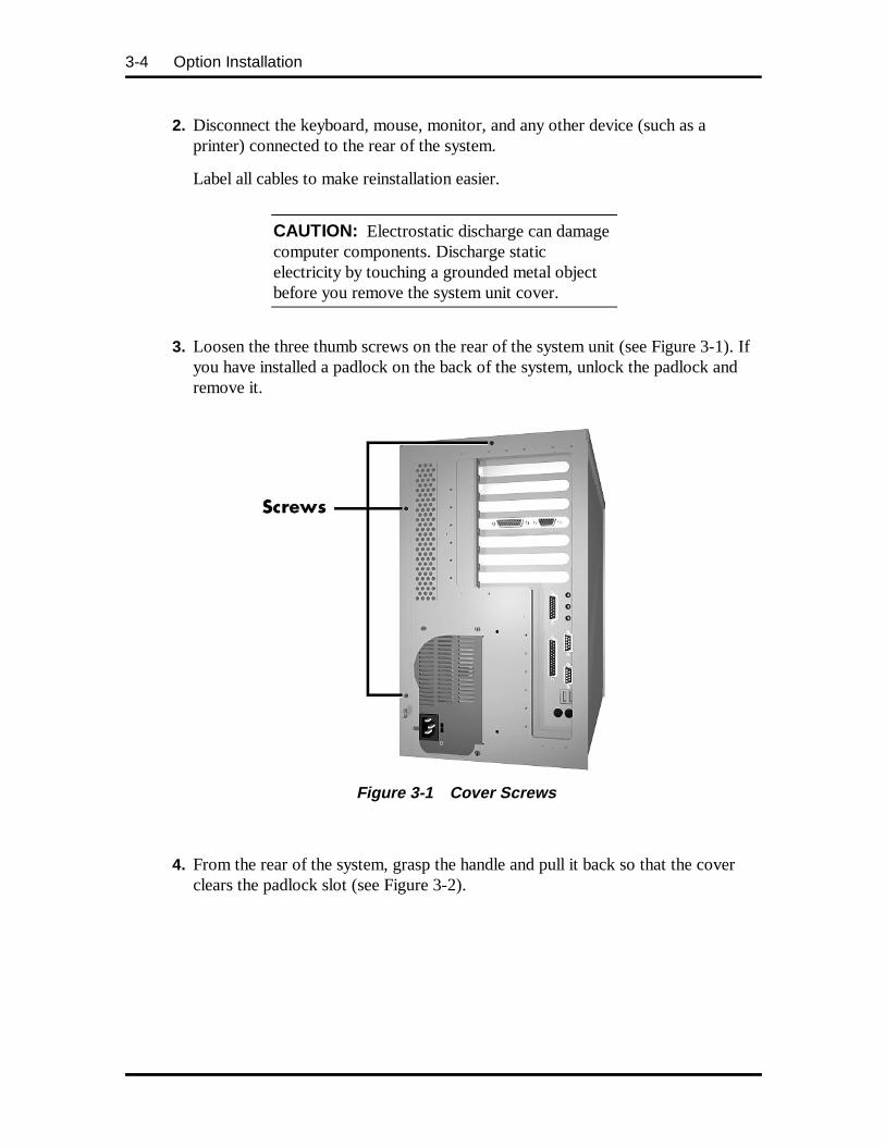
3-4 Option Installation
2. Disconnect the keyboard, mouse, monitor, and any other device (such as aprinter) connected to the rear of the system.
Label all cables to make reinstallation easier.
CAUTION: Electrostatic discharge can damagecomputer components. Discharge staticelectricity by touching a grounded metal objectbefore you remove the system unit cover.
3. Loosen the three thumb screws on the rear of the system unit (see Figure 3-1). Ifyou have installed a padlock on the back of the system, unlock the padlock andremove it.
Figure 3-1 Cover Screws
4. From the rear of the system, grasp the handle and pull it back so that the coverclears the padlock slot (see Figure 3-2).
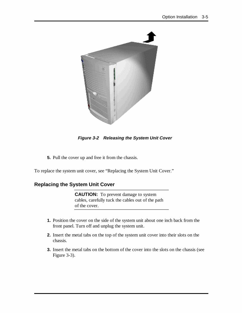
Option Installation 3-5
Figure 3-2 Releasing the System Unit Cover
5. Pull the cover up and free it from the chassis.
To replace the system unit cover, see “Replacing the System Unit Cover.”
Replacing the System Unit Cover
CAUTION: To prevent damage to systemcables, carefully tuck the cables out of the pathof the cover.
1. Position the cover on the side of the system unit about one inch back from thefront panel. Turn off and unplug the system unit.
2. Insert the metal tabs on the top of the system unit cover into their slots on thechassis.
3. Insert the metal tabs on the bottom of the cover into the slots on the chassis (seeFigure 3-3).
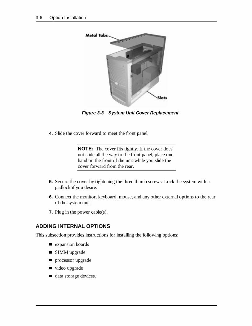
3-6 Option Installation
Figure 3-3 System Unit Cover Replacement
4. Slide the cover forward to meet the front panel.
NOTE: The cover fits tightly. If the cover doesnot slide all the way to the front panel, place onehand on the front of the unit while you slide thecover forward from the rear.
5. Secure the cover by tightening the three thumb screws. Lock the system with apadlock if you desire.
6. Connect the monitor, keyboard, mouse, and any other external options to the rearof the system unit.
7. Plug in the power cable(s).
ADDING INTERNAL OPTIONS
This subsection provides instructions for installing the following options:
� expansion boards
� SIMM upgrade
� processor upgrade
� video upgrade
� data storage devices.
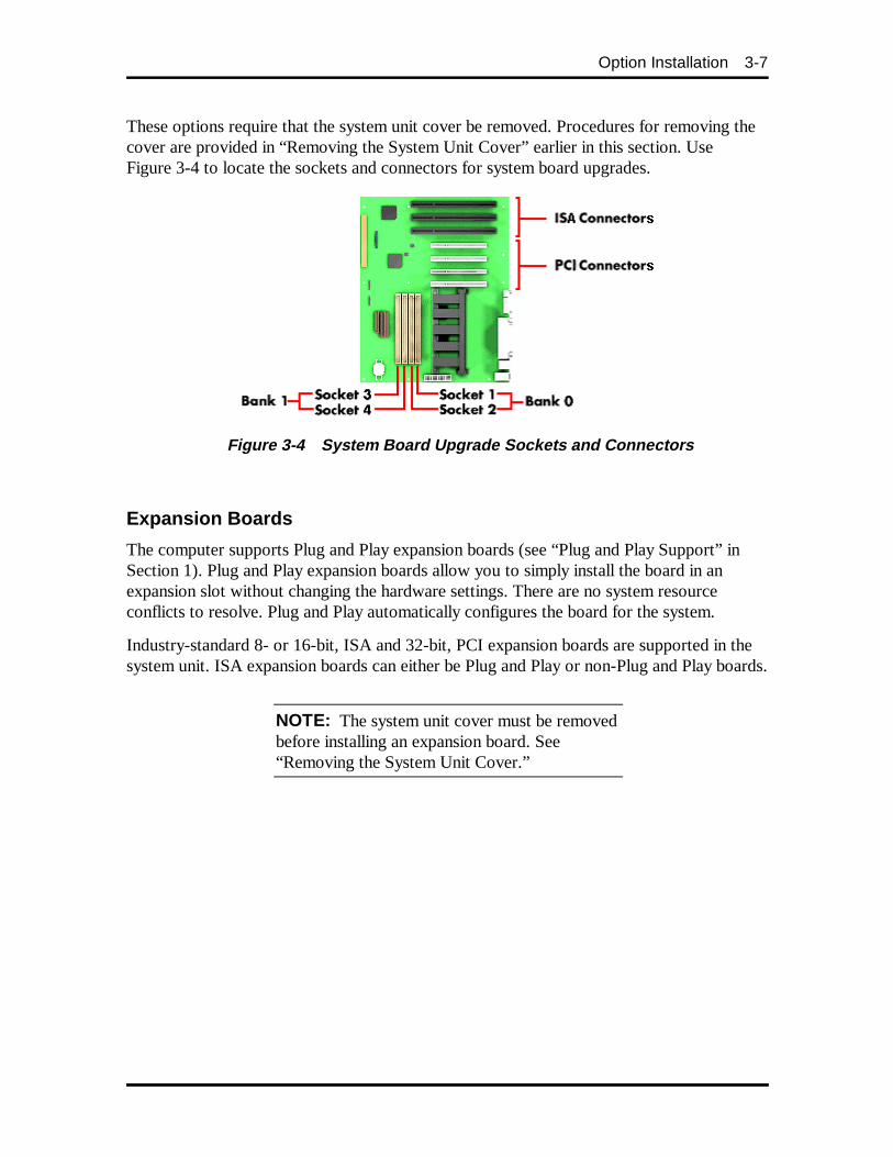
Option Installation 3-7
These options require that the system unit cover be removed. Procedures for removing thecover are provided in “Removing the System Unit Cover” earlier in this section. UseFigure 3-4 to locate the sockets and connectors for system board upgrades.
Figure 3-4 System Board Upgrade Sockets and C onnectors
Expansion Boards
The computer supports Plug and Play expansion boards (see “Plug and Play Support” inSection 1). Plug and Play expansion boards allow you to simply install the board in anexpansion slot without changing the hardware settings. There are no system resourceconflicts to resolve. Plug and Play automatically configures the board for the system.
Industry-standard 8- or 16-bit, ISA and 32-bit, PCI expansion boards are supported in thesystem unit. ISA expansion boards can either be Plug and Play or non-Plug and Play boards.
NOTE: The system unit cover must be removedbefore installing an expansion board. See“Removing the System Unit Cover.”
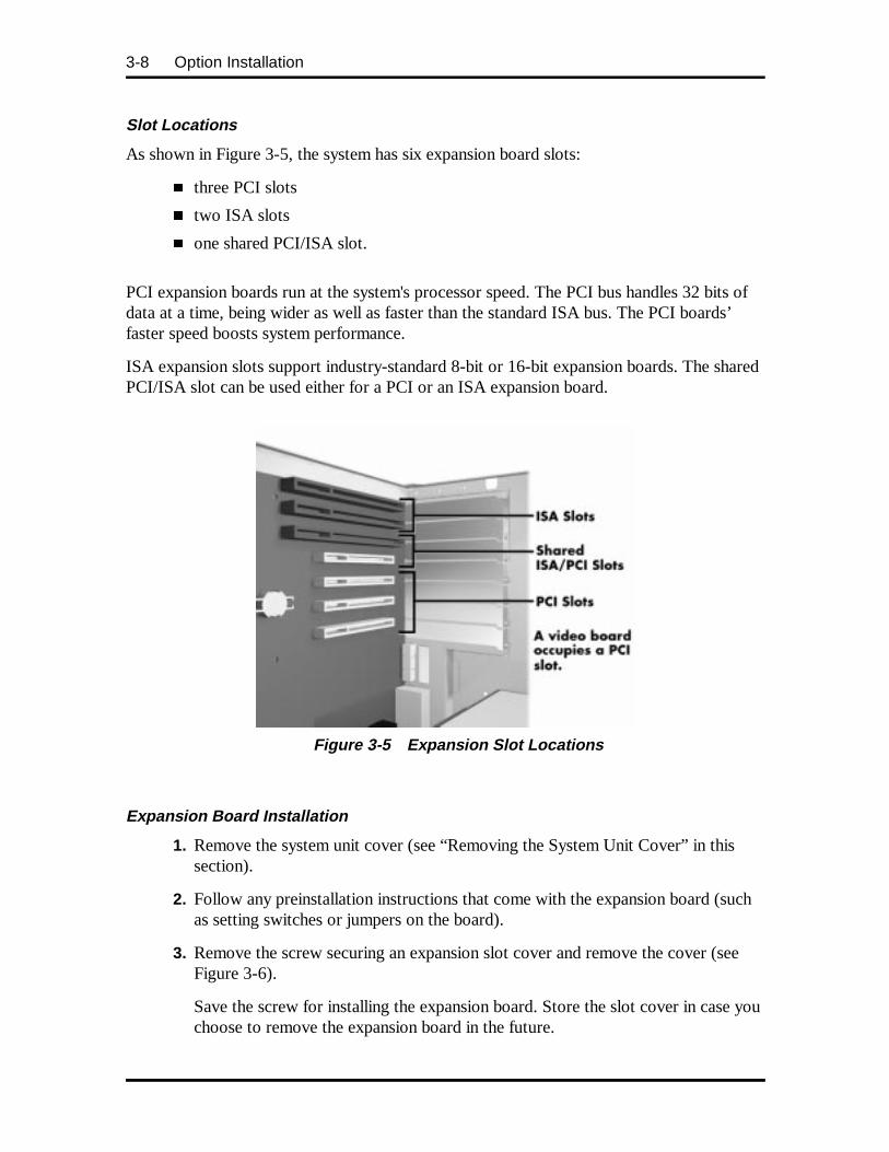
3-8 Option Installation
Slot Locations
As shown in Figure 3-5, the system has six expansion board slots:
� three PCI slots
� two ISA slots
� one shared PCI/ISA slot.
PCI expansion boards run at the system's processor speed. The PCI bus handles 32 bits ofdata at a time, being wider as well as faster than the standard ISA bus. The PCI boards’faster speed boosts system performance.
ISA expansion slots support industry-standard 8-bit or 16-bit expansion boards. The sharedPCI/ISA slot can be used either for a PCI or an ISA expansion board.
Figure 3-5 Expansion Slot Locations
Expansion Board Installation
1. Remove the system unit cover (see “Removing the System Unit Cover” in thissection).
2. Follow any preinstallation instructions that come with the expansion board (suchas setting switches or jumpers on the board).
3. Remove the screw securing an expansion slot cover and remove the cover (seeFigure 3-6).
Save the screw for installing the expansion board. Store the slot cover in case youchoose to remove the expansion board in the future.
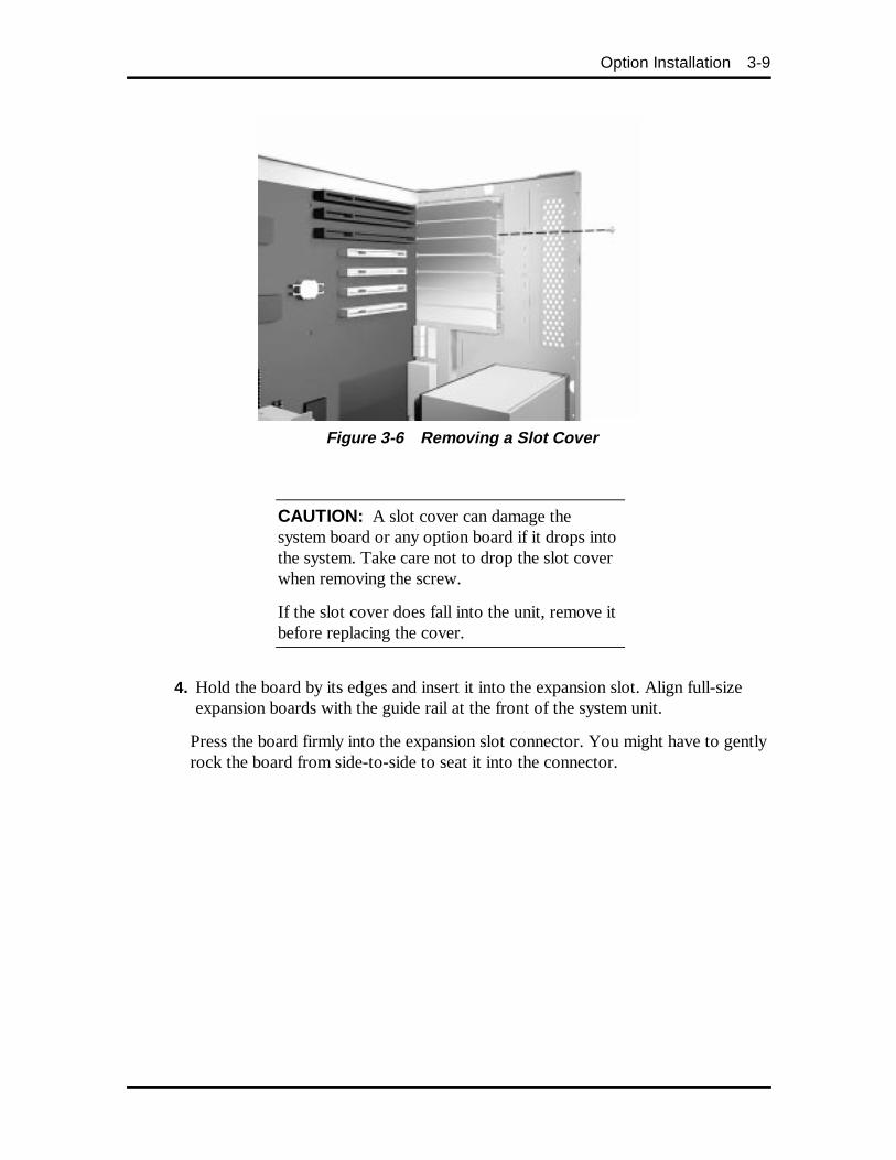
Option Installation 3-9
Figure 3-6 Removing a Slot Cover
CAUTION: A slot cover can damage thesystem board or any option board if it drops intothe system. Take care not to drop the slot coverwhen removing the screw.
If the slot cover does fall into the unit, remove itbefore replacing the cover.
4. Hold the board by its edges and insert it into the expansion slot. Align full-sizeexpansion boards with the guide rail at the front of the system unit.
Press the board firmly into the expansion slot connector. You might have to gentlyrock the board from side-to-side to seat it into the connector.
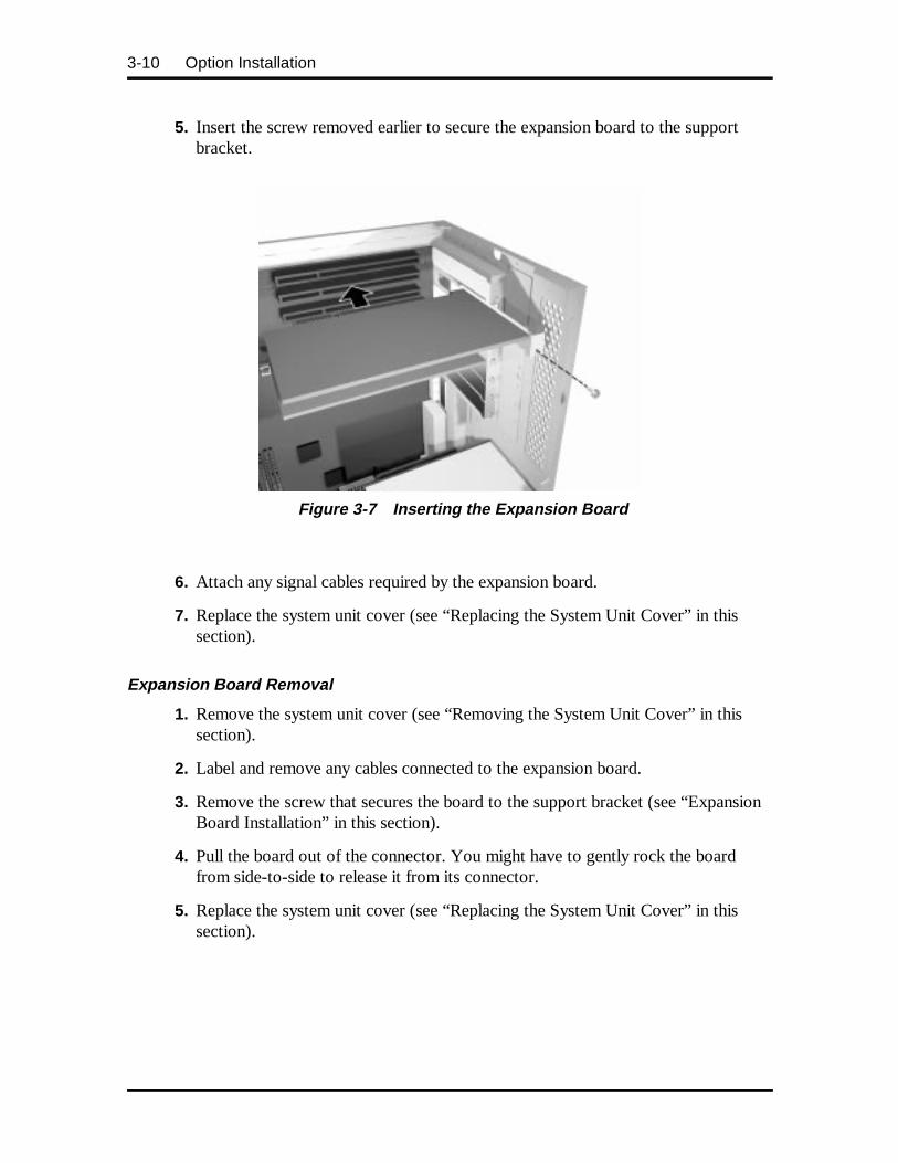
3-10 Option Installation
5. Insert the screw removed earlier to secure the expansion board to the supportbracket.
Figure 3-7 Inserting the Expansion Board
6. Attach any signal cables required by the expansion board.
7. Replace the system unit cover (see “Replacing the System Unit Cover” in thissection).
Expansion Board Removal
1. Remove the system unit cover (see “Removing the System Unit Cover” in thissection).
2. Label and remove any cables connected to the expansion board.
3. Remove the screw that secures the board to the support bracket (see “ExpansionBoard Installation” in this section).
4. Pull the board out of the connector. You might have to gently rock the boardfrom side-to-side to release it from its connector.
5. Replace the system unit cover (see “Replacing the System Unit Cover” in thissection).
Option Installation 3-11
SIMM Upgrade
SIMM sticks are installed into SIMM sockets on the system board. The system boardprovides four SIMM sockets and supports up to 256 MB of high-speed memory usingindustry-standard, tin-plated, single in-line memory modules (SIMMs). The system supportsthe following SIMMs:
� 1-MB by 32- or 36-bit (4-MB stick)
� 2-MB by 32-or 36-bit (8-MB stick)
� 4-MB by 32- or 36-bit (16-MB stick)
� 8-MB by 32-or 36-bit (32-MB stick)
� 16-MB by 32- or 36-bit (64-MB stick).
36-bit SIMMs may be used, but parity generation and checking is not supported.
NOTE: The system ships with EDO SIMMs.SIMM sockets must contain the same sizeSIMMs.
SIMM memory must be installed in pairs of thesame memory type.
The factory-installed SIMMs are installed inbank 1 (sockets 3 and 4). Bank 0 (sockets 1 and2) is empty.
CAUTION: To avoid corrosion betweendifferent metals, only use tin-plated SIMM sticks.
To determine the memory needed for the memory upgrade, see Table 3-1. See “SIMMInstallation” in this section when installing the SIMMs.
Checking the Memory in the System
Use the following procedure to:
� check the memory installed in the system
� determine the SIMM configuration you need to increase the memory
� identify the correct sockets for SIMM installation.
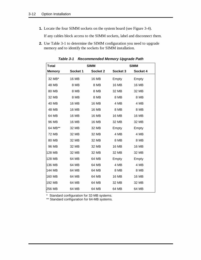
3-12 Option Installation
1. Locate the four SIMM sockets on the system board (see Figure 3-4).
If any cables block access to the SIMM sockets, label and disconnect them.
2. Use Table 3-1 to determine the SIMM configuration you need to upgradememory and to identify the sockets for SIMM installation.
Table 3-1 Recommended Memory Upgrade Path
Total SIMM SIMM
Memory Socket 1 Socket 2 Socket 3 Socket 4
32 MB* 16 MB 16 MB Empty Empty
48 MB 8 MB 8 MB 16 MB 16 MB
80 MB 8 MB 8 MB 32 MB 32 MB
32 MB 8 MB 8 MB 8 MB 8 MB
40 MB 16 MB 16 MB 4 MB 4 MB
48 MB 16 MB 16 MB 8 MB 8 MB
64 MB 16 MB 16 MB 16 MB 16 MB
96 MB 16 MB 16 MB 32 MB 32 MB
64 MB** 32 MB 32 MB Empty Empty
72 MB 32 MB 32 MB 4 MB 4 MB
80 MB 32 MB 32 MB 8 MB 8 MB
96 MB 32 MB 32 MB 16 MB 16 MB
128 MB 32 MB 32 MB 32 MB 32 MB
128 MB 64 MB 64 MB Empty Empty
136 MB 64 MB 64 MB 4 MB 4 MB
144 MB 64 MB 64 MB 8 MB 8 MB
160 MB 64 MB 64 MB 16 MB 16 MB
192 MB 64 MB 64 MB 32 MB 32 MB
256 MB 64 MB 64 MB 64 MB 64 MB
* Standard configuration for 32-MB systems.** Standard configuration for 64-MB systems.
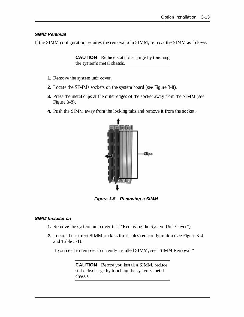
Option Installation 3-13
SIMM Removal
If the SIMM configuration requires the removal of a SIMM, remove the SIMM as follows.
CAUTION: Reduce static discharge by touchingthe system's metal chassis.
1. Remove the system unit cover.
2. Locate the SIMMs sockets on the system board (see Figure 3-8).
3. Press the metal clips at the outer edges of the socket away from the SIMM (seeFigure 3-8).
4. Push the SIMM away from the locking tabs and remove it from the socket.
Figure 3-8 Removing a SIMM
SIMM Installation
1. Remove the system unit cover (see “Removing the System Unit Cover”).
2. Locate the correct SIMM sockets for the desired configuration (see Figure 3-4and Table 3-1).
If you need to remove a currently installed SIMM, see “SIMM Removal.”
CAUTION: Before you install a SIMM, reducestatic discharge by touching the system's metalchassis.
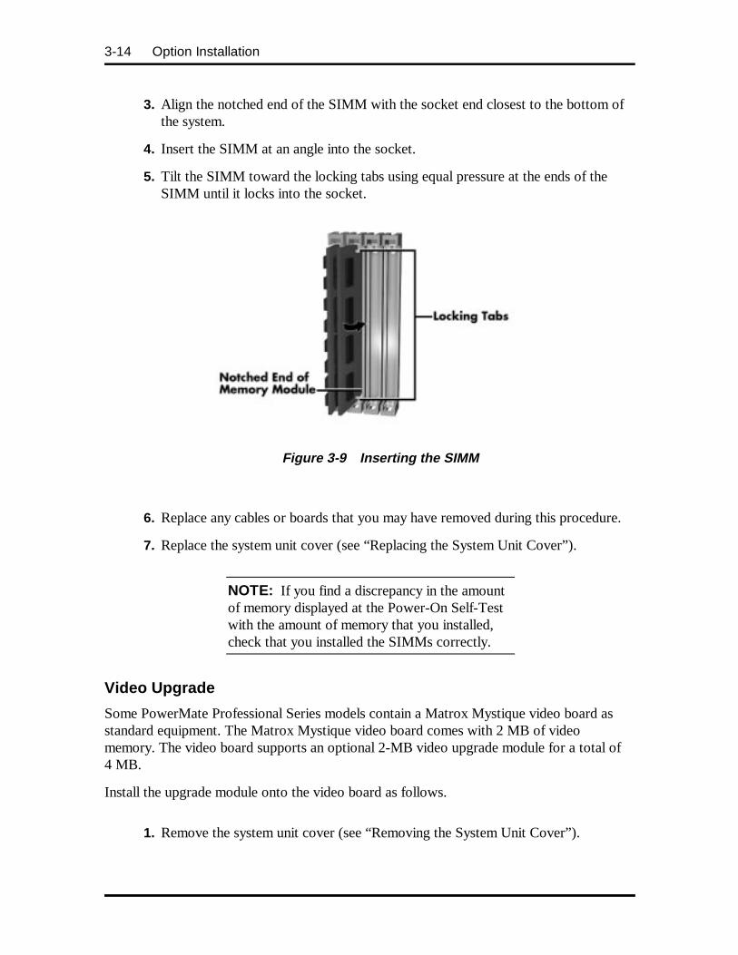
3-14 Option Installation
3. Align the notched end of the SIMM with the socket end closest to the bottom ofthe system.
4. Insert the SIMM at an angle into the socket.
5. Tilt the SIMM toward the locking tabs using equal pressure at the ends of theSIMM until it locks into the socket.
Figure 3-9 Inserting the SIMM
6. Replace any cables or boards that you may have removed during this procedure.
7. Replace the system unit cover (see “Replacing the System Unit Cover”).
NOTE: If you find a discrepancy in the amountof memory displayed at the Power-On Self-Testwith the amount of memory that you installed,check that you installed the SIMMs correctly.
Video Upgrade
Some PowerMate Professional Series models contain a Matrox Mystique video board asstandard equipment. The Matrox Mystique video board comes with 2 MB of videomemory. The video board supports an optional 2-MB video upgrade module for a total of4 MB.
Install the upgrade module onto the video board as follows.
1. Remove the system unit cover (see “Removing the System Unit Cover”).
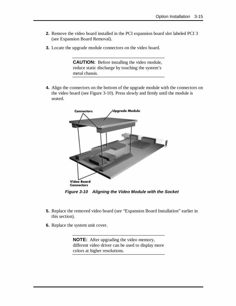
Option Installation 3-15
2. Remove the video board installed in the PCI expansion board slot labeled PCI 3(see Expansion Board Removal).
3. Locate the upgrade module connectors on the video board.
CAUTION: Before installing the video module,reduce static discharge by touching the system’smetal chassis.
4. Align the connectors on the bottom of the upgrade module with the connectors onthe video board (see Figure 3-10). Press slowly and firmly until the module isseated.
Figure 3-10 Aligning the Video Module with the So cket
5. Replace the removed video board (see “Expansion Board Installation” earlier inthis section).
6. Replace the system unit cover.
NOTE: After upgrading the video memory,different video driver can be used to display morecolors at higher resolutions.
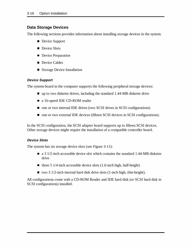
3-16 Option Installation
Data Storage Devices
The following sections provides information about installing storage devices in the system.
� Device Support
� Device Slots
� Device Preparation
� Device Cables
� Storage Device Installation
Device Support
The system board in the computer supports the following peripheral storage devices:
� up to two diskette drives, including the standard 1.44-MB diskette drive
� a 16-speed IDE CD-ROM reader
� one or two internal IDE drives (two SCSI drives in SCSI configurations)
� one or two external IDE devices (fifteen SCSI devices in SCSI configurations).
In the SCSI configuration, the SCSI adapter board supports up to fifteen SCSI devices.Other storage devices might require the installation of a compatible controller board.
Device Slots
The system has six storage device slots (see Figure 3-11):
� a 3 1/2-inch accessible device slot which contains the standard 1.44-MB diskettedrive
� three 5 1/4-inch accessible device slots (1.6-inch high, half-height)
� two 3 1/2-inch internal hard disk drive slots (1-inch high, thin-height).
All configurations come with a CD-ROM Reader and IDE hard disk (or SCSI hard disk inSCSI configurations) installed.
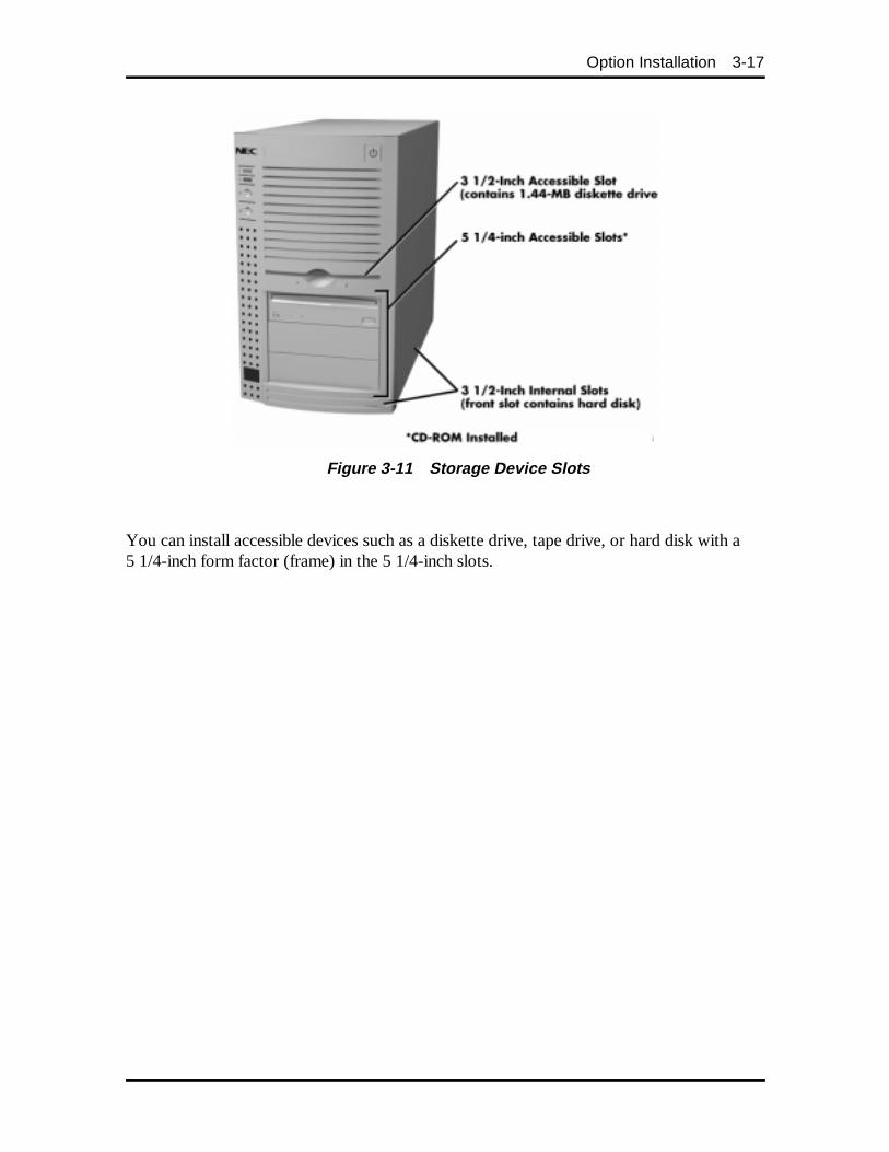
Option Installation 3-17
Figure 3-11 Storage Device Slots
You can install accessible devices such as a diskette drive, tape drive, or hard disk with a5 1/4-inch form factor (frame) in the 5 1/4-inch slots.
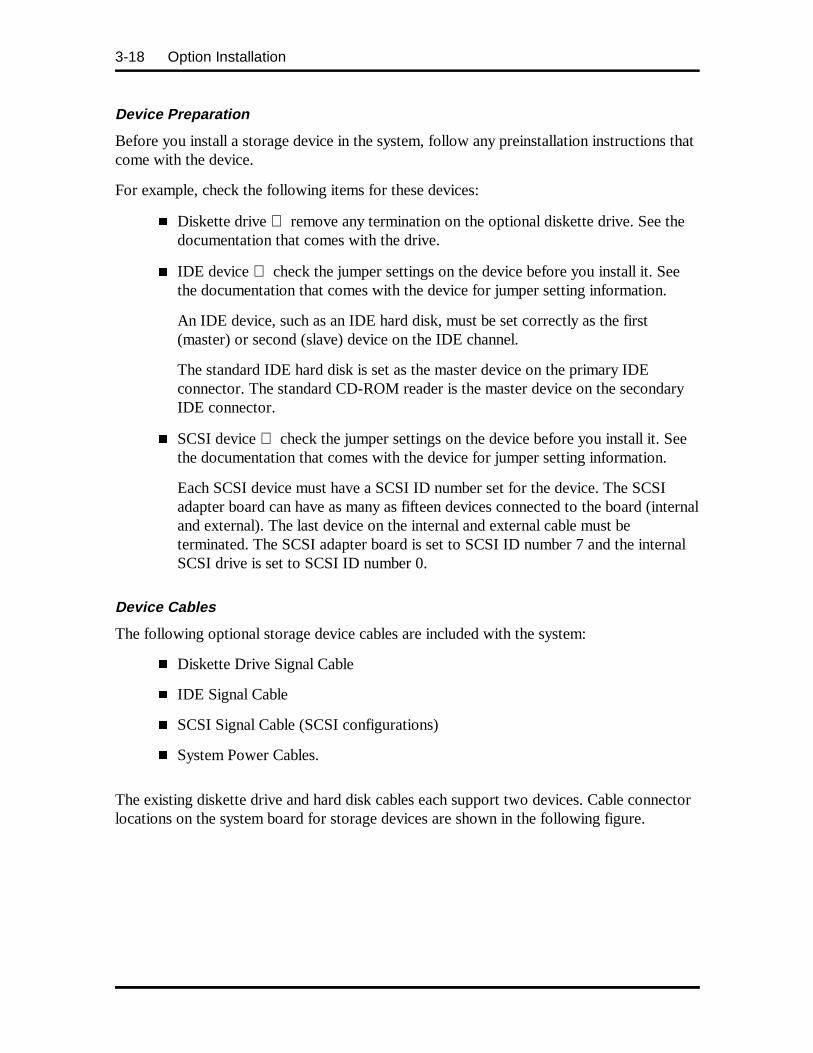
3-18 Option Installation
Device Preparation
Before you install a storage device in the system, follow any preinstallation instructions thatcome with the device.
For example, check the following items for these devices:
� Diskette drive remove any termination on the optional diskette drive. See thedocumentation that comes with the drive.
� IDE device check the jumper settings on the device before you install it. Seethe documentation that comes with the device for jumper setting information.
An IDE device, such as an IDE hard disk, must be set correctly as the first(master) or second (slave) device on the IDE channel.
The standard IDE hard disk is set as the master device on the primary IDEconnector. The standard CD-ROM reader is the master device on the secondaryIDE connector.
� SCSI device check the jumper settings on the device before you install it. Seethe documentation that comes with the device for jumper setting information.
Each SCSI device must have a SCSI ID number set for the device. The SCSIadapter board can have as many as fifteen devices connected to the board (internaland external). The last device on the internal and external cable must beterminated. The SCSI adapter board is set to SCSI ID number 7 and the internalSCSI drive is set to SCSI ID number 0.
Device Cables
The following optional storage device cables are included with the system:
� Diskette Drive Signal Cable
� IDE Signal Cable
� SCSI Signal Cable (SCSI configurations)
� System Power Cables.
The existing diskette drive and hard disk cables each support two devices. Cable connectorlocations on the system board for storage devices are shown in the following figure.
Option Installation 3-19
Figure 3-12 System Board Cable Connectors
Diskette Drive Signal Cable
A three-connector diskette drive signal cable comes attached to the system board and to thestandard 1.44-MB diskette drive.
The installation of a second diskette drive in the system does not require the replacement ofthe existing diskette drive signal cable. Connect an optional diskette drive to the middleconnector on the standard diskette drive signal cable.
The colored edge of the cable goes to pin 1 on the cable connector. Align the red edge ofthe cable with pin 1 (the notched end) on the drive connector.
The following figure shows the standard three-connector diskette drive signal cable.
Figure 3-13 Diskette Drive Signal Cable
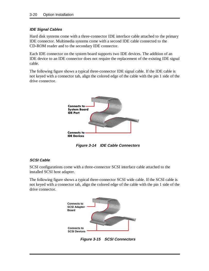
3-20 Option Installation
IDE Signal Cables
Hard disk systems come with a three-connector IDE interface cable attached to the primaryIDE connector. Multimedia systems come with a second IDE cable connected to theCD-ROM reader and to the secondary IDE connector.
Each IDE connector on the system board supports two IDE devices. The addition of anIDE device to an IDE connector does not require the replacement of the existing IDE signalcable.
The following figure shows a typical three-connector IDE signal cable. If the IDE cable isnot keyed with a connector tab, align the colored edge of the cable with the pin 1 side of thedrive connector.
Figure 3-14 IDE Cable Connectors
SCSI Cable
SCSI configurations come with a three-connector SCSI interface cable attached to theinstalled SCSI host adapter.
The following figure shows a typical three-connector SCSI wide cable. If the SCSI cable isnot keyed with a connector tab, align the colored edge of the cable with the pin 1 side of thedrive connector.
Figure 3-15 SCSI Connectors
Connects toSCSI AdapterBoard
Connects toSCSI Devices
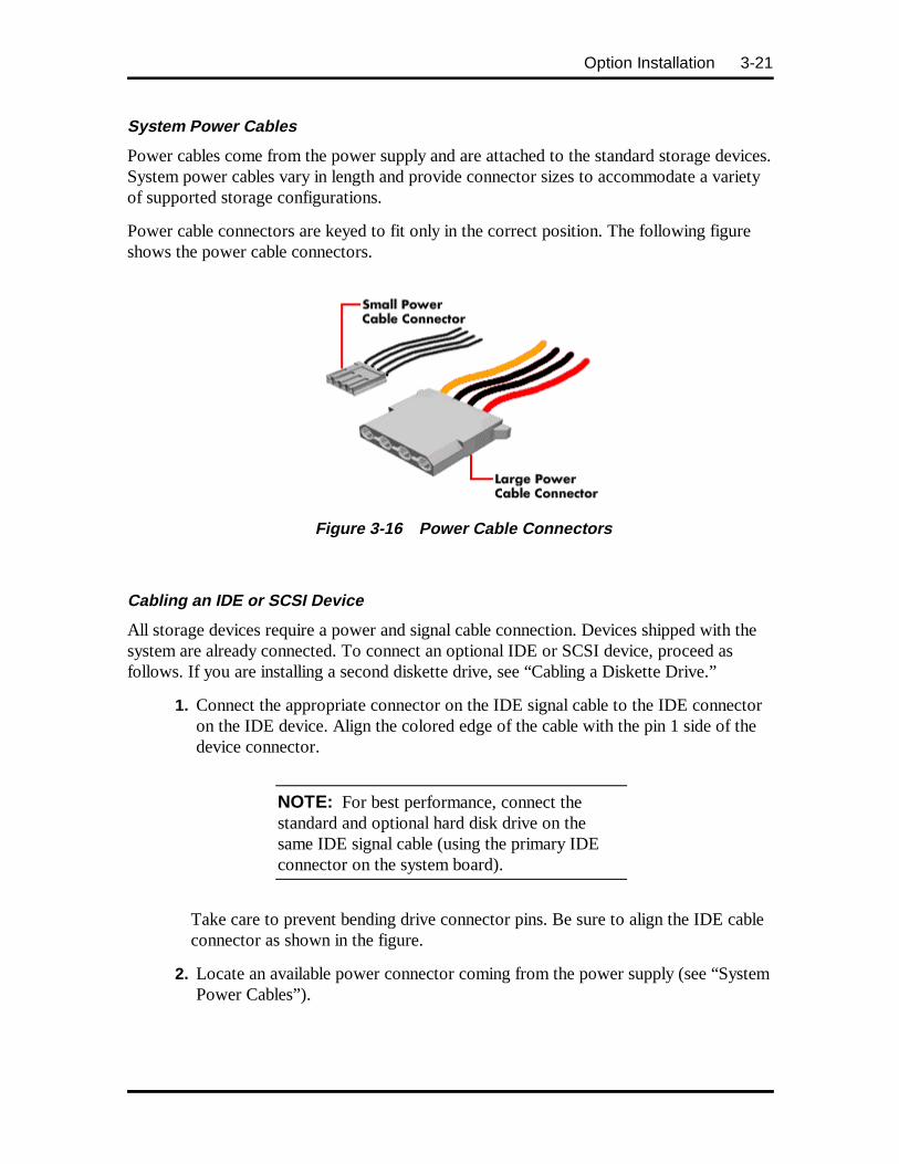
Option Installation 3-21
System Power Cables
Power cables come from the power supply and are attached to the standard storage devices.System power cables vary in length and provide connector sizes to accommodate a varietyof supported storage configurations.
Power cable connectors are keyed to fit only in the correct position. The following figureshows the power cable connectors.
Figure 3-16 Power Cable Connectors
Cabling an IDE or SCSI Device
All storage devices require a power and signal cable connection. Devices shipped with thesystem are already connected. To connect an optional IDE or SCSI device, proceed asfollows. If you are installing a second diskette drive, see “Cabling a Diskette Drive.”
1. Connect the appropriate connector on the IDE signal cable to the IDE connectoron the IDE device. Align the colored edge of the cable with the pin 1 side of thedevice connector.
NOTE: For best performance, connect thestandard and optional hard disk drive on thesame IDE signal cable (using the primary IDEconnector on the system board).
Take care to prevent bending drive connector pins. Be sure to align the IDE cableconnector as shown in the figure.
2. Locate an available power connector coming from the power supply (see “SystemPower Cables”).
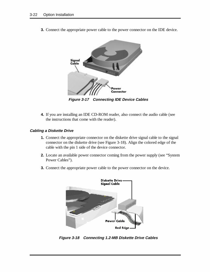
3-22 Option Installation
3. Connect the appropriate power cable to the power connector on the IDE device.
Figure 3-17 Connecting IDE Device Cables
4. If you are installing an IDE CD-ROM reader, also connect the audio cable (seethe instructions that come with the reader).
Cabling a Diskette Drive
1. Connect the appropriate connector on the diskette drive signal cable to the signalconnector on the diskette drive (see Figure 3-18). Align the colored edge of thecable with the pin 1 side of the device connector.
2. Locate an available power connector coming from the power supply (see “SystemPower Cables”).
3. Connect the appropriate power cable to the power connector on the device.
Figure 3-18 Connecting 1.2-MB Diskette Drive Cables
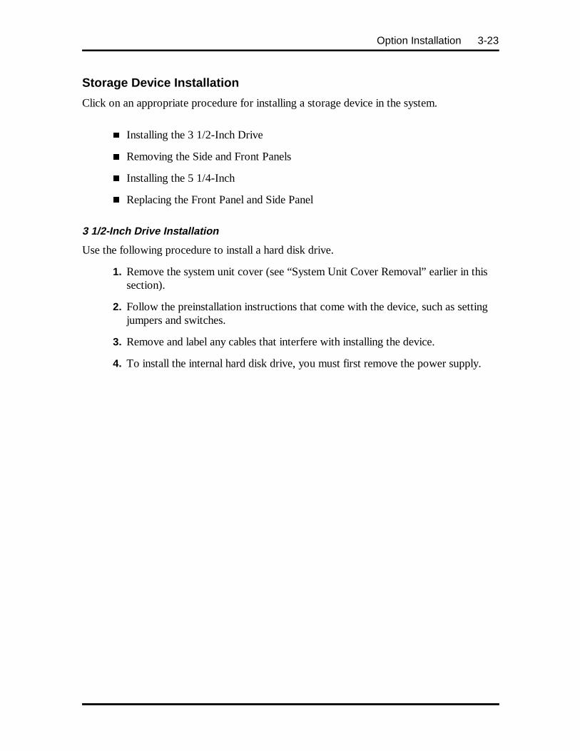
Option Installation 3-23
Storage Device Installation
Click on an appropriate procedure for installing a storage device in the system.
� Installing the 3 1/2-Inch Drive
� Removing the Side and Front Panels
� Installing the 5 1/4-Inch
� Replacing the Front Panel and Side Panel
3 1/2-Inch Drive Installation
Use the following procedure to install a hard disk drive.
1. Remove the system unit cover (see “System Unit Cover Removal” earlier in thissection).
2. Follow the preinstallation instructions that come with the device, such as settingjumpers and switches.
3. Remove and label any cables that interfere with installing the device.
4. To install the internal hard disk drive, you must first remove the power supply.
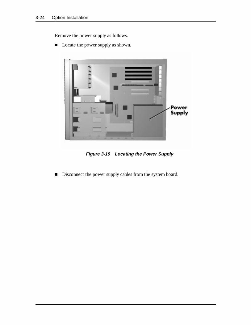
3-24 Option Installation
Remove the power supply as follows.
� Locate the power supply as shown.
Figure 3-19 Locating the Power Supply
� Disconnect the power supply cables from the system board.
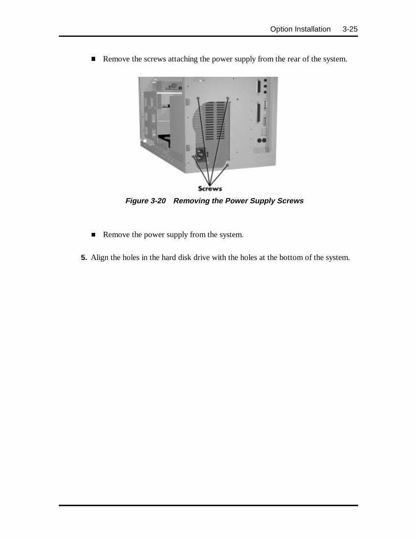
Option Installation 3-25
� Remove the screws attaching the power supply from the rear of the system.
Figure 3-20 Removing the Power Supply Screws
� Remove the power supply from the system.
5. Align the holes in the hard disk drive with the holes at the bottom of the system.
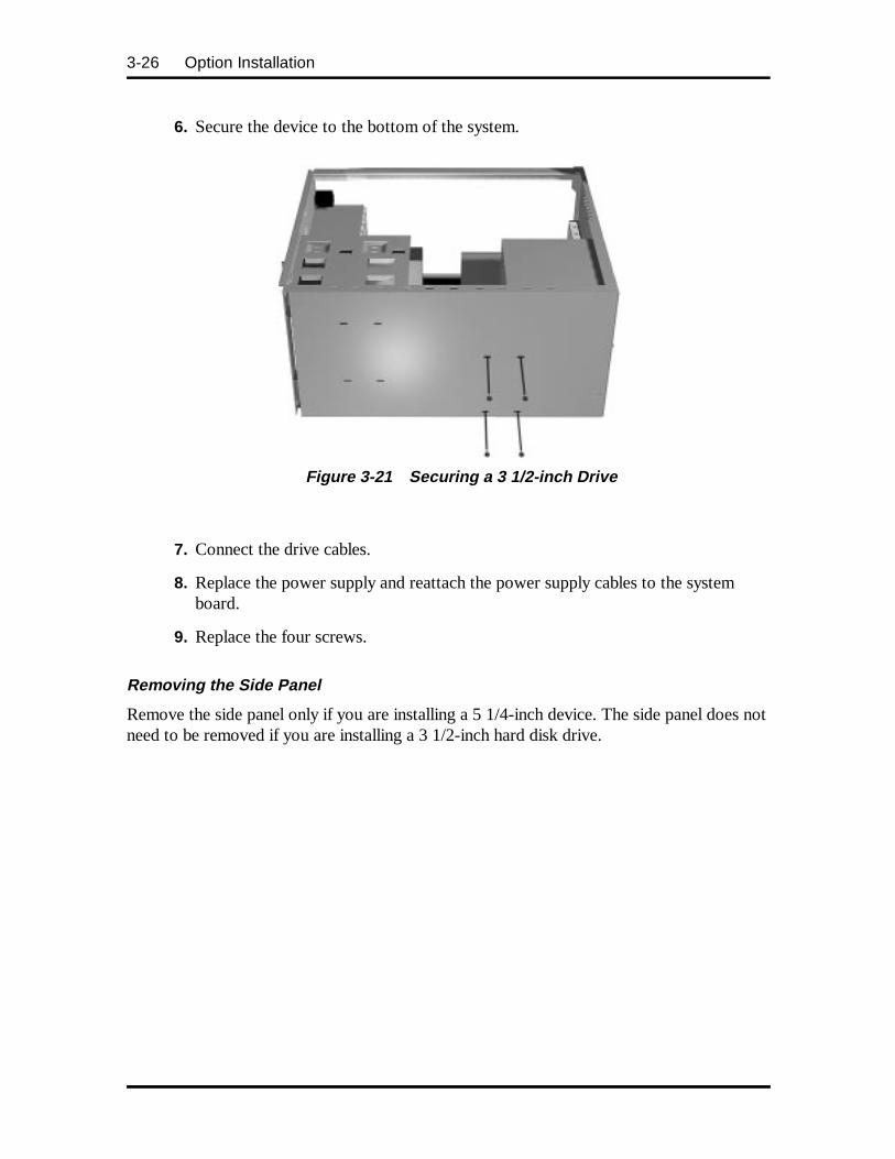
3-26 Option Installation
6. Secure the device to the bottom of the system.
Figure 3-21 Securing a 3 1/2-inch Drive
7. Connect the drive cables.
8. Replace the power supply and reattach the power supply cables to the systemboard.
9. Replace the four screws.
Removing the Side Panel
Remove the side panel only if you are installing a 5 1/4-inch device. The side panel does notneed to be removed if you are installing a 3 1/2-inch hard disk drive.
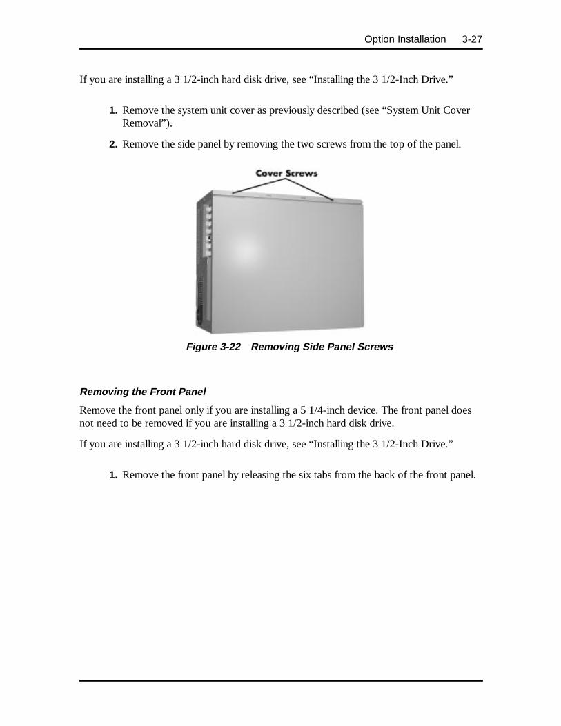
Option Installation 3-27
If you are installing a 3 1/2-inch hard disk drive, see “Installing the 3 1/2-Inch Drive.”
1. Remove the system unit cover as previously described (see “System Unit CoverRemoval”).
2. Remove the side panel by removing the two screws from the top of the panel.
Figure 3-22 Removing Side Panel Screws
Removing the Front Panel
Remove the front panel only if you are installing a 5 1/4-inch device. The front panel doesnot need to be removed if you are installing a 3 1/2-inch hard disk drive.
If you are installing a 3 1/2-inch hard disk drive, see “Installing the 3 1/2-Inch Drive.”
1. Remove the front panel by releasing the six tabs from the back of the front panel.
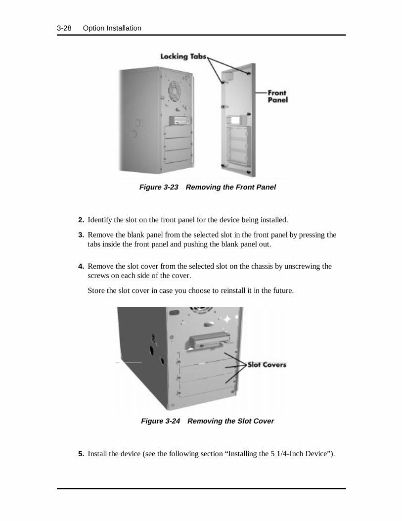
3-28 Option Installation
Figure 3-23 Removing the Front Panel
2. Identify the slot on the front panel for the device being installed.
3. Remove the blank panel from the selected slot in the front panel by pressing thetabs inside the front panel and pushing the blank panel out.
4. Remove the slot cover from the selected slot on the chassis by unscrewing thescrews on each side of the cover.
Store the slot cover in case you choose to reinstall it in the future.
Figure 3-24 Removing the Slot Cover
5. Install the device (see the following section “Installing the 5 1/4-Inch Device”).
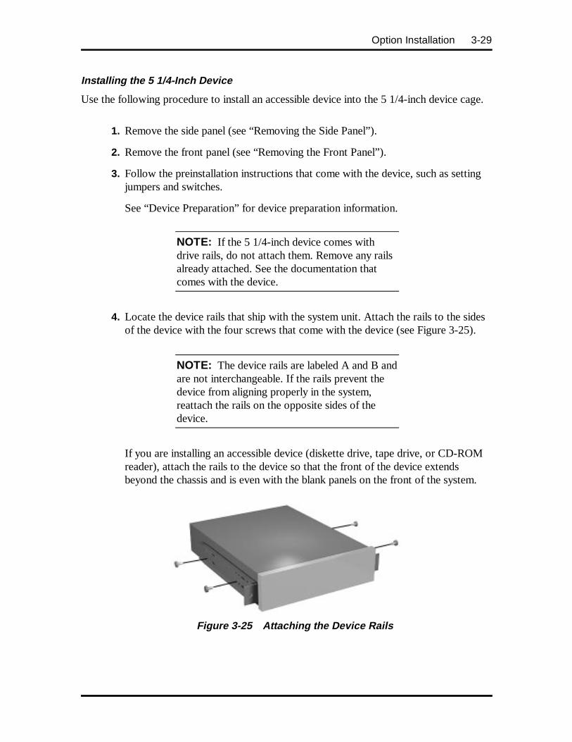
Option Installation 3-29
Installing the 5 1/4-Inch Device
Use the following procedure to install an accessible device into the 5 1/4-inch device cage.
1. Remove the side panel (see “Removing the Side Panel”).
2. Remove the front panel (see “Removing the Front Panel”).
3. Follow the preinstallation instructions that come with the device, such as settingjumpers and switches.
See “Device Preparation” for device preparation information.
NOTE: If the 5 1/4-inch device comes withdrive rails, do not attach them. Remove any railsalready attached. See the documentation thatcomes with the device.
4. Locate the device rails that ship with the system unit. Attach the rails to the sidesof the device with the four screws that come with the device (see Figure 3-25).
NOTE: The device rails are labeled A and B andare not interchangeable. If the rails prevent thedevice from aligning properly in the system,reattach the rails on the opposite sides of thedevice.
If you are installing an accessible device (diskette drive, tape drive, or CD-ROMreader), attach the rails to the device so that the front of the device extendsbeyond the chassis and is even with the blank panels on the front of the system.
Figure 3-25 Attaching the Device Rails

3-30 Option Installation
5. From the front of the system unit, insert the device (connector end first) into thedevice slot.
6. Connect the device cables (see “Device Cabling”).
7. Align the holes in the device with the holes in the sides of the system unit.
Secure the device to the system with the four screws, two to a side, that comewith the device. Use the two screws you removed from the slot cover to securethe drive in place on the front of the system chassis.
Figure 3-26 Inserting the Device
8. Replace the system unit front panel and side panel (see “Replacing the Front andSide Panels”).
9. Replace the system unit cover (see “Replacing the System Unit Cover”).
NOTE: If you installed a 1.2-MB diskette drive,remove the protective cardboard insert from thedrive.
10. Run the Setup program to set the new configuration (see Section 2).
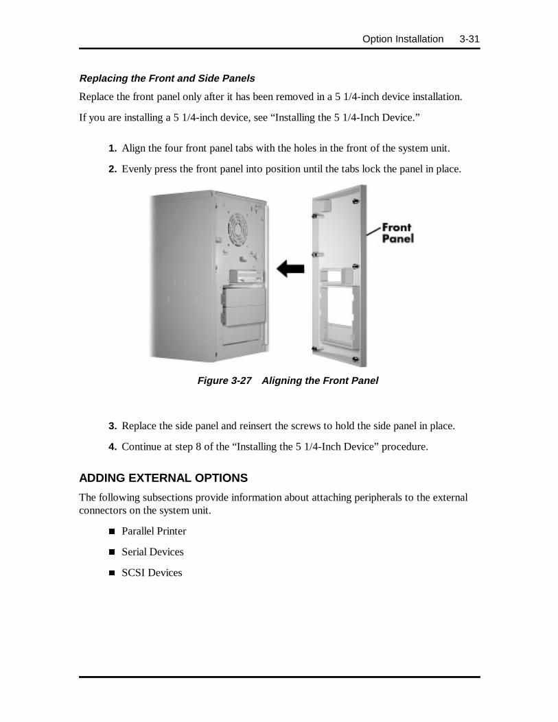
Option Installation 3-31
Replacing the Front and Side Panels
Replace the front panel only after it has been removed in a 5 1/4-inch device installation.
If you are installing a 5 1/4-inch device, see “Installing the 5 1/4-Inch Device.”
1. Align the four front panel tabs with the holes in the front of the system unit.
2. Evenly press the front panel into position until the tabs lock the panel in place.
Figure 3-27 Aligning the Front Panel
3. Replace the side panel and reinsert the screws to hold the side panel in place.
4. Continue at step 8 of the “Installing the 5 1/4-Inch Device” procedure.
ADDING EXTERNAL OPTIONS
The following subsections provide information about attaching peripherals to the externalconnectors on the system unit.
� Parallel Printer
� Serial Devices
� SCSI Devices
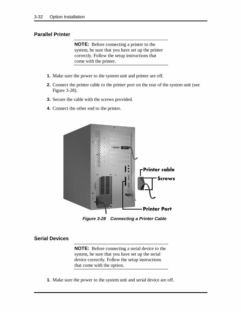
3-32 Option Installation
Parallel Printer
NOTE: Before connecting a printer to thesystem, be sure that you have set up the printercorrectly. Follow the setup instructions thatcome with the printer.
1. Make sure the power to the system unit and printer are off.
2. Connect the printer cable to the printer port on the rear of the system unit (seeFigure 3-28).
3. Secure the cable with the screws provided.
4. Connect the other end to the printer.
Figure 3-28 Connecting a Printer Cable
Serial Devices
NOTE: Before connecting a serial device to thesystem, be sure that you have set up the serialdevice correctly. Follow the setup instructionsthat come with the option.
1. Make sure the power to the system unit and serial device are off.
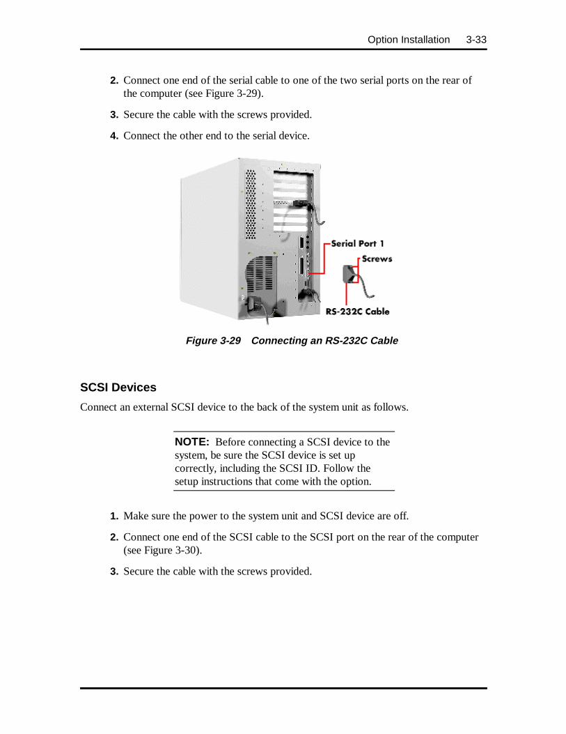
Option Installation 3-33
2. Connect one end of the serial cable to one of the two serial ports on the rear ofthe computer (see Figure 3-29).
3. Secure the cable with the screws provided.
4. Connect the other end to the serial device.
Figure 3-29 Connecting an RS-232C Cable
SCSI Devices
Connect an external SCSI device to the back of the system unit as follows.
NOTE: Before connecting a SCSI device to thesystem, be sure the SCSI device is set upcorrectly, including the SCSI ID. Follow thesetup instructions that come with the option.
1. Make sure the power to the system unit and SCSI device are off.
2. Connect one end of the SCSI cable to the SCSI port on the rear of the computer(see Figure 3-30).
3. Secure the cable with the screws provided.
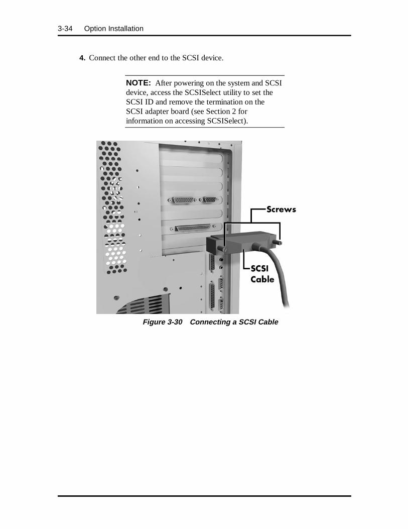
3-34 Option Installation
4. Connect the other end to the SCSI device.
NOTE: After powering on the system and SCSIdevice, access the SCSISelect utility to set theSCSI ID and remove the termination on theSCSI adapter board (see Section 2 forinformation on accessing SCSISelect).
Figure 3-30 Connecting a SCSI Cable
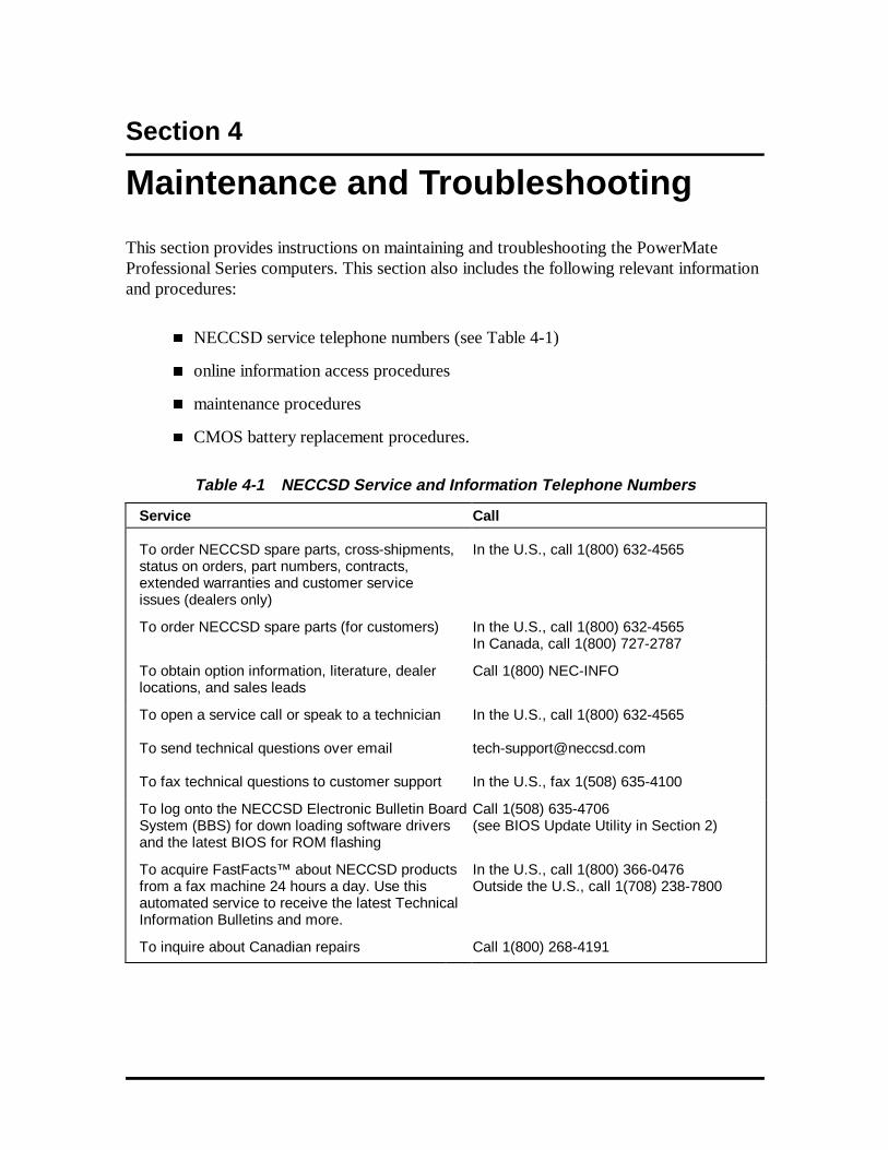
Section 4
Maintenance and Troubleshooting
This section provides instructions on maintaining and troubleshooting the PowerMateProfessional Series computers. This section also includes the following relevant informationand procedures:
� NECCSD service telephone numbers (see Table 4-1)
� online information access procedures
� maintenance procedures
� CMOS battery replacement procedures.
Table 4-1 NECCSD Service and Information Telephone Numbers
Service Call
To order NECCSD spare parts, cross-shipments,status on orders, part numbers, contracts,extended warranties and customer serviceissues (dealers only)
In the U.S., call 1(800) 632-4565
To order NECCSD spare parts (for customers) In the U.S., call 1(800) 632-4565In Canada, call 1(800) 727-2787
To obtain option information, literature, dealerlocations, and sales leads
Call 1(800) NEC-INFO
To open a service call or speak to a technician
To send technical questions over email
To fax technical questions to customer support
In the U.S., call 1(800) 632-4565
In the U.S., fax 1(508) 635-4100
To log onto the NECCSD Electronic Bulletin BoardSystem (BBS) for down loading software driversand the latest BIOS for ROM flashing
Call 1(508) 635-4706(see BIOS Update Utility in Section 2)
To acquire FastFacts™ about NECCSD productsfrom a fax machine 24 hours a day. Use thisautomated service to receive the latest TechnicalInformation Bulletins and more.
In the U.S., call 1(800) 366-0476Outside the U.S., call 1(708) 238-7800
To inquire about Canadian repairs Call 1(800) 268-4191
4-2 Maintenance and Troubleshooting
ONLINE SERVICES
The following sections provide valuable information on how to access the various onlineservices available for your use.
NEC’s FastFacts Service
NEC’s FastFacts service is a self-help, automated electronic information service forobtaining up-to-date product application notes, installation procedures, troubleshootingtips, data sheets, technical information bulletins, illustrated parts lists, part numbers, andother information about the system.
Using a fax machine, you can obtain information from FastFacts 24 hours a day, 7 days aweek. You simply call the FastFacts number on a touch-tone telephone, order theinformation you want by following the voice prompts, and FastFacts will automatically faxthe information to you.
If you are new to FastFacts, you should first order one of the following catalogs. Eachcatalog lists the available documents and their document numbers. Current catalogs include:
� Catalog 1, NEC Graphics Products
� Catalog 2, NEC CD-ROM, Printers, and Disk Drive Products
� Catalog 3, NECCSD Computer Products
� Catalog 5, NECCSD Factory Refurbished Product List
� Catalog 6, NECCSD Select Direct Pricing
� Catalog 7, NECCSD Technical Support Notes, Technical Information Bulletins,Illustrated Parts Lists.
Order information from FastFacts as follows. If you would like instructions for usingFastFacts, request document number 63233469 when prompted.
1. Be sure that the fax machine or fax/modem is on. Have the document numberready for the document you want.
2. At the touch-tone telephone, enter 800-366-0476 (U.S. and Canada only).
For international use, enter the international long distance access number, the U.S.country code, and the U.S. telephone number (708-238-7800).
Maintenance and Troubleshooting 4-3
3. Listen to the instructions provided by the voice prompts.
Press 1 if you do not want an introduction to FastFacts. Follow the automatedinstructions for ordering the document or catalog.
Press 2 if you want an introduction to FastFacts. Follow the automatedinstructions for ordering the catalog or document.
4. When prompted, enter your fax number and name.
For international use, first enter the international long distance access number(011), your country code, your area code or city code, then your fax number.
The information you requested is automatically sent to your fax machine. It is importantthat you wait for the ordered document to arrive at the fax machine before calling to ordermore documents. If FastFacts attempts to send the second order before the first order iscompleted, the order may be canceled. After three tries, FastFacts assumes that your line isbusy and terminates any further processing of the order.
NECCSD Bulletin Board Service
If you have access to a modem, you can use the NECCSD Bulletin Board Service (BBS) toprovide you with the latest information on hardware and software. The BBS allows you todownload files (video drivers, printer drivers, BIOS updates, etc.) for system enhancementsand upgrades.
You can also access the BBS through the CompuServe online service.
Log onto the BBS as follows.
1. From the Windows 95 desktop, click the Start button.
2. Point to Programs. Point to Accessories and then click HyperTerminal.
3. Double click the Hypertrm.exe icon. The HyperTerminal program appears.
4. Follow the instructions on the screen to set up your modem. Click theHyperTerminal Help button for information about dialing the phone number.
If you need to check communications settings, check that the settings match thefollowing BBS parameters.
� Baud rate: select any baud rate that matches your modem
� Parity: none
� Data bits: 8
� Stop bits: 1
4-4 Maintenance and Troubleshooting
� Flow control: Xon/Xoff (select Hardware if using 14.4 bps or higher)
5. Following the HyperTerminal instructions, enter the BBS phone number(508-635-4706). Your business phone system and/or location might require a9 1 or 1 prefix.
NOTE: The first time that you use the BBS,you are requested to provide information for anew user questionnaire.
6. Press Enter twice
7. Enter your first name, last name, and password. Press Enter after each.
8. Follow the screen prompts until the Main Menu is displayed.
9. At the Main Menu, select J to join a conference. Select Conference 1 for thedesktop conference.
10. From the Main Menu, press F and Enter for the File menu.
11. At the File menu, select F for a list of downloadable files. Follow the prompts toselect a file for downloading.
CAUTION: Executable files automaticallyformat your diskette when you download filesfrom the BBS. Formatting destroys any data onthe diskette. Before you download files from theBBS, check that you do not have information onthe diskette that you need.
After you complete downloading your file, log off the BBS as follows:
1. Press Enter (to continue)
2. Press G (command for Goodbye/Hangup).
3. Press Enter .
Maintenance and Troubleshooting 4-5
E-mail/Fax Technical Support Service
If you have a modem, the NECCSD Technical Support Center offers technical support byE-mail over the Internet network. The Internet address is:
tech-support@n eccsd.com
If you have access to a fax machine or fax/modem, you can also fax technical questions tothe NECCSD Technical Support Center. The fax number is:
(508) 635-4100
When using the E-mail or fax support service, include the following words in the subjectfield for prompt response from the appropriate technical person:
� Desktop (desktop or minitower systems)
� Monitor
� CD-ROM
� Printer
� Notebook.
Provide as much specific information about your questions as possible. Also, if you aresending a fax, please include your voice telephone number and your fax number with thequestion. You will receive a response to your questions within one business day.
Internet
If you have a modem, you can access NECCSD’s Home Page on the Internet World WideWeb. You can do this through a commercial online service or through your Internetaccount. NECCSD’s Home Page contains general information about NECCSD products.
You can also use the Internet to access NECCSD’s ftp (file transfer protocol) site todownload various files (video drivers, printer drivers, BIOS updates). The files areessentially the same files as on the NECCSD Bulletin Board Service.
To access the World-Wide-Web NECCSD Home Page, enter the following InternetUniform Resource Locator (URL) through your service:
http://www.n eccsd.com/
To access the NECCSD ftp Site, enter the following Internet ftp address through yourservice:
ftp.nectech.com
Once in the file menu, follow the prompts to choose and download the file(s) you want.

4-6 Maintenance and Troubleshooting
NECCSD Technical Support Services
NECCSD also offers direct technical support through its Technical Support Center.(NECCSD technical support is for U.S. and Canadian customers only; internationalcustomers should check with their sales provider.)
Direct assistance is available 24 hours a day, seven days a week. Call the NECCSDTechnical Support Center, toll free, at 1-800-632-4565 (for U.S. only).
Free technical support for hardware is limited to the length of the standard warranty.Software support for preloaded software is limited to 90 days from the time of the first callto the NECCSD Technical Support Center. For software support after the initial 90 days orhardware support after the warranty period, the charges are $30.00 per incident.
Before calling , please have available your system’s name, model number, serial number,and as much information as possible about your system’s problem.
For outside the U.S., please contact your local NECCSD sales provider.
MAINTENANCE
This subsection contains general information for cleaning and checking the system,keyboard, and monitor.
The system, keyboard, and monitor require cleaning and checking at least once a year (andmore often if operating in a dusty environment). No other scheduled maintenance orlubrication is required.
WARNING: Unplug all power cords beforeperforming any maintenance. Voltage is presentinside the system and monitor even after thepower button is off. All voltage is removed onlywhen the power cord is unplugged.
System Cleaning
Use the following procedure to clean the system:
1. Power off the system and unplug all power cables.
2. Periodically wipe the outside of the system, keyboard, mouse, and monitor with asoft, clean cloth. Remove stains with a mild detergent. Do not use solvents orstrong, abrasive cleaners on any part of the system.
3. Clean the monitor screen with a commercial monitor screen cleaning kit. Or use aglass cleaner, then wipe with a clean lint-free cloth.
Maintenance and Troubleshooting 4-7
4. Local distributors and dealers may sell diskette drive head cleaning kits. These kitscontain special diskettes and cleaning solution. Do not use the abrasive headcleaning kits (kits without cleaning solution). Insert the diskette immediately afterpowering on the system, before the disk boot-up. Allow the diskette drive headsto clean for about 30 seconds.
Keyboard Cleaning
When necessary, inspect and clean the inside of the keyboard as follows:
1. Remove the six screws holding the keyboard enclosure together.
NOTE: The keyboard and cable together areconsidered a whole-unit, field-replaceableassembly. Disassembly of the keyboard isnecessary only when cleaning the inside.
2. Separate the two halves of the enclosure. Clean the enclosure and keys with adamp cloth. A small, soft-bristle brush may be used to clean between the keys. Donot wet or dampen the keyboard's printed circuit board (PCB). If the PCBaccidentally gets wet, thoroughly dry it before reattaching the keyboard to thesystem unit.
Mouse Cleaning
Under normal conditions, the mouse has a self-cleaning mechanism that prevents a buildupof dust or lint around the mouse ball and tracking mechanism. Periodically, however, themouse ball must be cleaned. Use the following procedure to clean the mouse.
1. Unplug the mouse from the system.
2. Turn the mouse upside down and locate the mouse ball cover (see Figure 4-1).
3. Turn the ball cover clockwise and remove the cover.
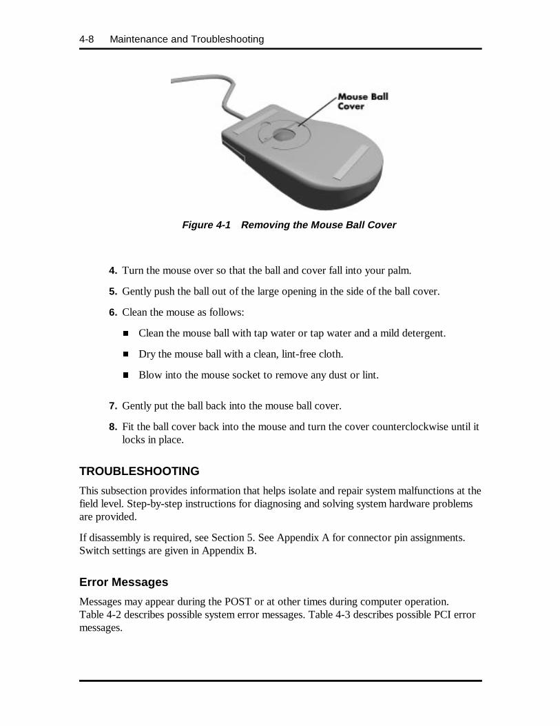
4-8 Maintenance and Troubleshooting
Figure 4-1 Removing the Mouse Ball Cover
4. Turn the mouse over so that the ball and cover fall into your palm.
5. Gently push the ball out of the large opening in the side of the ball cover.
6. Clean the mouse as follows:
� Clean the mouse ball with tap water or tap water and a mild detergent.
� Dry the mouse ball with a clean, lint-free cloth.
� Blow into the mouse socket to remove any dust or lint.
7. Gently put the ball back into the mouse ball cover.
8. Fit the ball cover back into the mouse and turn the cover counterclockwise until itlocks in place.
TROUBLESHOOTING
This subsection provides information that helps isolate and repair system malfunctions at thefield level. Step-by-step instructions for diagnosing and solving system hardware problemsare provided.
If disassembly is required, see Section 5. See Appendix A for connector pin assignments.Switch settings are given in Appendix B.
Error Messages
Messages may appear during the POST or at other times during computer operation.Table 4-2 describes possible system error messages. Table 4-3 describes possible PCI errormessages.
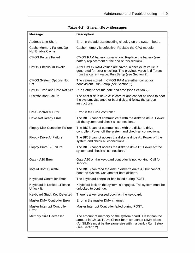
Maintenance and Troubleshooting 4-9
Table 4-2 System Error Messages
Message Description
Address Line Short Error in the address decoding circuitry on the system board.
Cache Memory Failure, DoNot Enable Cache
Cache memory is defective. Replace the CPU module.
CMOS Battery Failed CMOS RAM battery power is low. Replace the battery (seebattery replacement at the end of this section).
CMOS Checksum Invalid After CMOS RAM values are saved, a checksum value isgenerated for error checking. The previous value is differentfrom the current value. Run Setup (see Section 2).
CMOS System Options NotSet
The values stored in CMOS RAM are either corrupt ornonexistent. Run Setup (see Section 2).
CMOS Time and Date Not Set Run Setup to set the date and time (see Section 2).
Diskette Boot Failure The boot disk in drive A: is corrupt and cannot be used to bootthe system. Use another boot disk and follow the screeninstructions.
DMA Controller Error Error in the DMA controller.
Drive Not Ready Error The BIOS cannot communicate with the diskette drive. Poweroff the system and check all connections.
Floppy Disk Controller Failure The BIOS cannot communicate with the diskette drivecontroller. Power off the system and check all connections.
Floppy Drive A: Failure The BIOS cannot access the diskette drive A:. Power off thesystem and check all connections.
Floppy Drive B: Failure The BIOS cannot access the diskette drive B:. Power off thesystem and check all connections.
Gate - A20 Error Gate A20 on the keyboard controller is not working. Call forservice.
Invalid Boot Diskette The BIOS can read the disk in diskette drive A:, but cannotboot the system. Use another boot diskette.
Keyboard Controller Error The keyboard controller has failed during POST.
Keyboard is Locked...PleaseUnlock It.
Keyboard lock on the system is engaged. The system must beunlocked to continue.
Keyboard Stuck Key Detected There is a key pressed down on the keyboard.
Master DMA Controller Error Error in the master DMA channel.
Master Interrupt ControllerError
Master Interrupt Controller failed during POST.
Memory Size Decreased The amount of memory on the system board is less than theamount in CMOS RAM. Check for mismatched SIMM sizes.(All SIMMs must be the same size within a bank.) Run Setup(see Section 2).
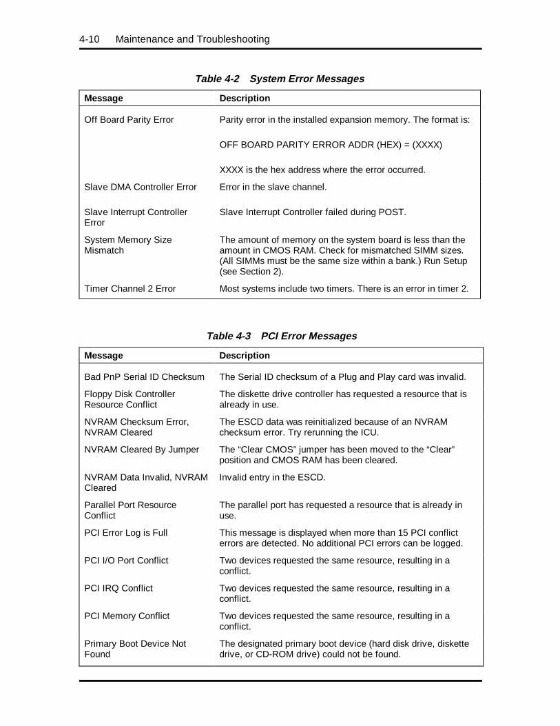
4-10 Maintenance and Troubleshooting
Table 4-2 System Error Messages
Message Description
Off Board Parity Error Parity error in the installed expansion memory. The format is:
OFF BOARD PARITY ERROR ADDR (HEX) = (XXXX)
XXXX is the hex address where the error occurred.
Slave DMA Controller Error Error in the slave channel.
Slave Interrupt ControllerError
Slave Interrupt Controller failed during POST.
System Memory SizeMismatch
The amount of memory on the system board is less than theamount in CMOS RAM. Check for mismatched SIMM sizes.(All SIMMs must be the same size within a bank.) Run Setup(see Section 2).
Timer Channel 2 Error Most systems include two timers. There is an error in timer 2.
Table 4-3 PCI Error Messages
Message Description
Bad PnP Serial ID Checksum The Serial ID checksum of a Plug and Play card was invalid.
Floppy Disk ControllerResource Conflict
The diskette drive controller has requested a resource that isalready in use.
NVRAM Checksum Error,NVRAM Cleared
The ESCD data was reinitialized because of an NVRAMchecksum error. Try rerunning the ICU.
NVRAM Cleared By Jumper The “Clear CMOS” jumper has been moved to the “Clear”position and CMOS RAM has been cleared.
NVRAM Data Invalid, NVRAMCleared
Invalid entry in the ESCD.
Parallel Port ResourceConflict
The parallel port has requested a resource that is already inuse.
PCI Error Log is Full This message is displayed when more than 15 PCI conflicterrors are detected. No additional PCI errors can be logged.
PCI I/O Port Conflict Two devices requested the same resource, resulting in aconflict.
PCI IRQ Conflict Two devices requested the same resource, resulting in aconflict.
PCI Memory Conflict Two devices requested the same resource, resulting in aconflict.
Primary Boot Device NotFound
The designated primary boot device (hard disk drive, diskettedrive, or CD-ROM drive) could not be found.
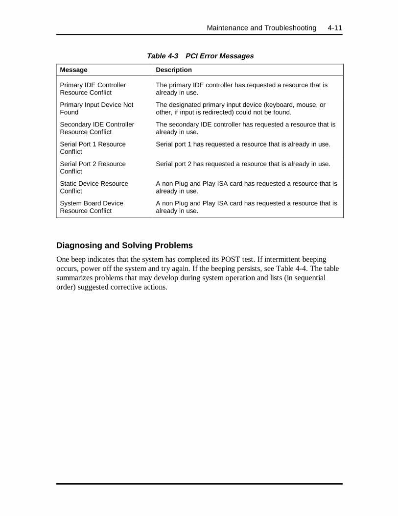
Maintenance and Troubleshooting 4-11
Table 4-3 PCI Error Messages
Message Description
Primary IDE ControllerResource Conflict
The primary IDE controller has requested a resource that isalready in use.
Primary Input Device NotFound
The designated primary input device (keyboard, mouse, orother, if input is redirected) could not be found.
Secondary IDE ControllerResource Conflict
The secondary IDE controller has requested a resource that isalready in use.
Serial Port 1 ResourceConflict
Serial port 1 has requested a resource that is already in use.
Serial Port 2 ResourceConflict
Serial port 2 has requested a resource that is already in use.
Static Device ResourceConflict
A non Plug and Play ISA card has requested a resource that isalready in use.
System Board DeviceResource Conflict
A non Plug and Play ISA card has requested a resource that isalready in use.
Diagnosing and Solving Problems
One beep indicates that the system has completed its POST test. If intermittent beepingoccurs, power off the system and try again. If the beeping persists, see Table 4-4. The tablesummarizes problems that may develop during system operation and lists (in sequentialorder) suggested corrective actions.
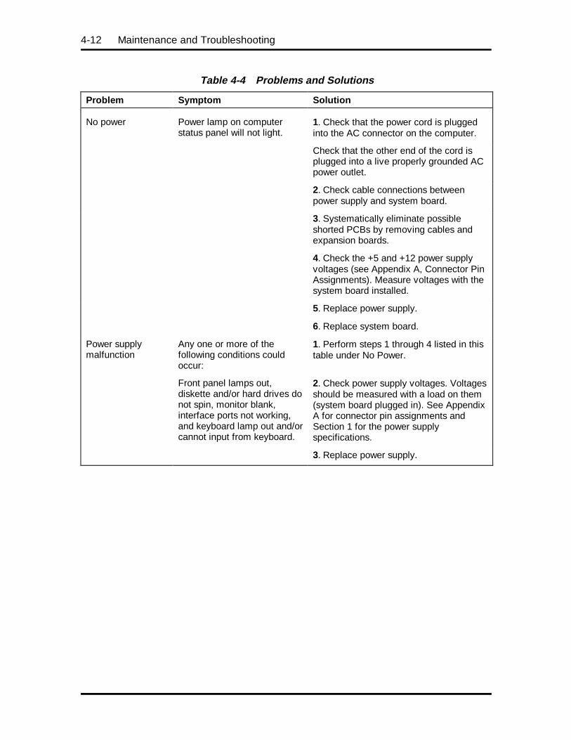
4-12 Maintenance and Troubleshooting
Table 4-4 Problems and Solutions
Problem Symptom Solution
No power Power lamp on computerstatus panel will not light.
1. Check that the power cord is pluggedinto the AC connector on the computer.
Check that the other end of the cord isplugged into a live properly grounded ACpower outlet.
2. Check cable connections betweenpower supply and system board.
3. Systematically eliminate possibleshorted PCBs by removing cables andexpansion boards.
4. Check the +5 and +12 power supplyvoltages (see Appendix A, Connector PinAssignments). Measure voltages with thesystem board installed.
5. Replace power supply.
6. Replace system board.
Power supplymalfunction
Any one or more of thefollowing conditions couldoccur:
1. Perform steps 1 through 4 listed in thistable under No Power.
Front panel lamps out,diskette and/or hard drives donot spin, monitor blank,interface ports not working,and keyboard lamp out and/orcannot input from keyboard.
2. Check power supply voltages. Voltagesshould be measured with a load on them(system board plugged in). See AppendixA for connector pin assignments andSection 1 for the power supplyspecifications.
3. Replace power supply.
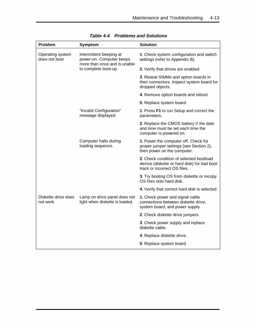
Maintenance and Troubleshooting 4-13
Table 4-4 Problems and Solutions
Problem Symptom Solution
Operating systemdoes not boot
Intermittent beeping atpower-on. Computer beepsmore than once and is unableto complete boot-up.
1. Check system configuration and switchsettings (refer to Appendix B).
2. Verify that drives are enabled.
3. Reseat SIMMs and option boards intheir connectors. Inspect system board fordropped objects.
4. Remove option boards and reboot.
5. Replace system board.
“Invalid Configuration”message displayed.
1. Press F1 to run Setup and correct theparameters.
2. Replace the CMOS battery if the dateand time must be set each time thecomputer is powered on.
Computer halts duringloading sequence.
1. Power the computer off. Check forproper jumper settings (see Section 2),then power on the computer.
2. Check condition of selected bootloaddevice (diskette or hard disk) for bad boottrack or incorrect OS files.
3. Try booting OS from diskette or recopyOS files onto hard disk.
4. Verify that correct hard disk is selected.
Diskette drive doesnot work
Lamp on drive panel does notlight when diskette is loaded.
1. Check power and signal cableconnections between diskette drive,system board, and power supply.
2. Check diskette drive jumpers.
3. Check power supply and replacediskette cable.
4. Replace diskette drive.
5. Replace system board.
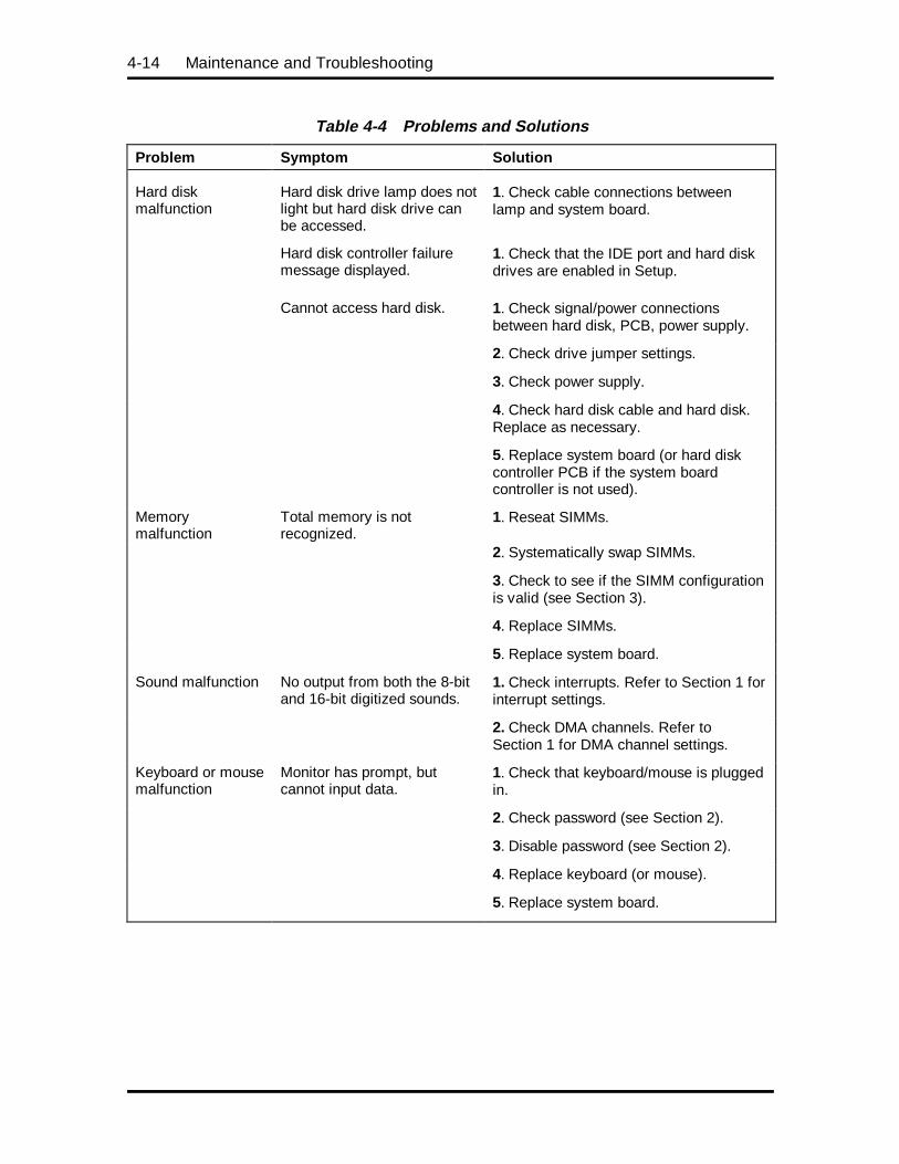
4-14 Maintenance and Troubleshooting
Table 4-4 Problems and Solutions
Problem Symptom Solution
Hard diskmalfunction
Hard disk drive lamp does notlight but hard disk drive canbe accessed.
1. Check cable connections betweenlamp and system board.
Hard disk controller failuremessage displayed.
1. Check that the IDE port and hard diskdrives are enabled in Setup.
Cannot access hard disk. 1. Check signal/power connectionsbetween hard disk, PCB, power supply.
2. Check drive jumper settings.
3. Check power supply.
4. Check hard disk cable and hard disk.Replace as necessary.
5. Replace system board (or hard diskcontroller PCB if the system boardcontroller is not used).
Memorymalfunction
Total memory is notrecognized.
1. Reseat SIMMs.
2. Systematically swap SIMMs.
3. Check to see if the SIMM configurationis valid (see Section 3).
4. Replace SIMMs.
5. Replace system board.
Sound malfunction No output from both the 8-bitand 16-bit digitized sounds.
1. Check interrupts. Refer to Section 1 forinterrupt settings.
2. Check DMA channels. Refer toSection 1 for DMA channel settings.
Keyboard or mousemalfunction
Monitor has prompt, butcannot input data.
1. Check that keyboard/mouse is pluggedin.
2. Check password (see Section 2).
3. Disable password (see Section 2).
4. Replace keyboard (or mouse).
5. Replace system board.
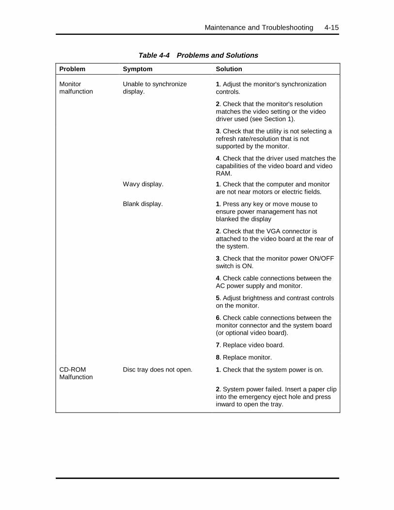
Maintenance and Troubleshooting 4-15
Table 4-4 Problems and Solutions
Problem Symptom Solution
Monitormalfunction
Unable to synchronizedisplay.
1. Adjust the monitor's synchronizationcontrols.
2. Check that the monitor's resolutionmatches the video setting or the videodriver used (see Section 1).
3. Check that the utility is not selecting arefresh rate/resolution that is notsupported by the monitor.
4. Check that the driver used matches thecapabilities of the video board and videoRAM.
Wavy display. 1. Check that the computer and monitorare not near motors or electric fields.
Blank display. 1. Press any key or move mouse toensure power management has notblanked the display
2. Check that the VGA connector isattached to the video board at the rear ofthe system.
3. Check that the monitor power ON/OFFswitch is ON.
4. Check cable connections between theAC power supply and monitor.
5. Adjust brightness and contrast controlson the monitor.
6. Check cable connections between themonitor connector and the system board(or optional video board).
7. Replace video board.
8. Replace monitor.
CD-ROMMalfunction
Disc tray does not open. 1. Check that the system power is on.
2. System power failed. Insert a paper clipinto the emergency eject hole and pressinward to open the tray.
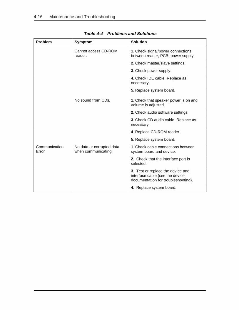
4-16 Maintenance and Troubleshooting
Table 4-4 Problems and Solutions
Problem Symptom Solution
Cannot access CD-ROMreader.
1. Check signal/power connectionsbetween reader, PCB, power supply.
2. Check master/slave settings.
3. Check power supply.
4. Check IDE cable. Replace asnecessary.
5. Replace system board.
No sound from CDs. 1. Check that speaker power is on andvolume is adjusted.
2. Check audio software settings.
3. Check CD audio cable. Replace asnecessary.
4. Replace CD-ROM reader.
5. Replace system board.
CommunicationError
No data or corrupted datawhen communicating.
1. Check cable connections betweensystem board and device.
2. Check that the interface port isselected.
3. Test or replace the device andinterface cable (see the devicedocumentation for troubleshooting).
4. Replace system board.
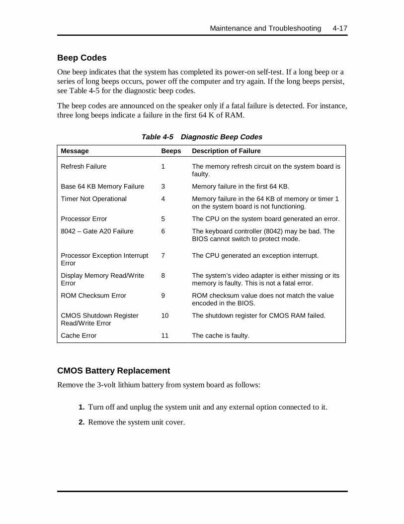
Maintenance and Troubleshooting 4-17
Beep Codes
One beep indicates that the system has completed its power-on self-test. If a long beep or aseries of long beeps occurs, power off the computer and try again. If the long beeps persist,see Table 4-5 for the diagnostic beep codes.
The beep codes are announced on the speaker only if a fatal failure is detected. For instance,three long beeps indicate a failure in the first 64 K of RAM.
Table 4-5 Diagnostic Beep Codes
Message Beeps Descript ion of Failure
Refresh Failure 1 The memory refresh circuit on the system board isfaulty.
Base 64 KB Memory Failure 3 Memory failure in the first 64 KB.
Timer Not Operational 4 Memory failure in the 64 KB of memory or timer 1on the system board is not functioning.
Processor Error 5 The CPU on the system board generated an error.
8042 – Gate A20 Failure 6 The keyboard controller (8042) may be bad. TheBIOS cannot switch to protect mode.
Processor Exception InterruptError
7 The CPU generated an exception interrupt.
Display Memory Read/WriteError
8 The system’s video adapter is either missing or itsmemory is faulty. This is not a fatal error.
ROM Checksum Error 9 ROM checksum value does not match the valueencoded in the BIOS.
CMOS Shutdown RegisterRead/Write Error
10 The shutdown register for CMOS RAM failed.
Cache Error 11 The cache is faulty.
CMOS Battery Replacement
Remove the 3-volt lithium battery from system board as follows:
1. Turn off and unplug the system unit and any external option connected to it.
2. Remove the system unit cover.
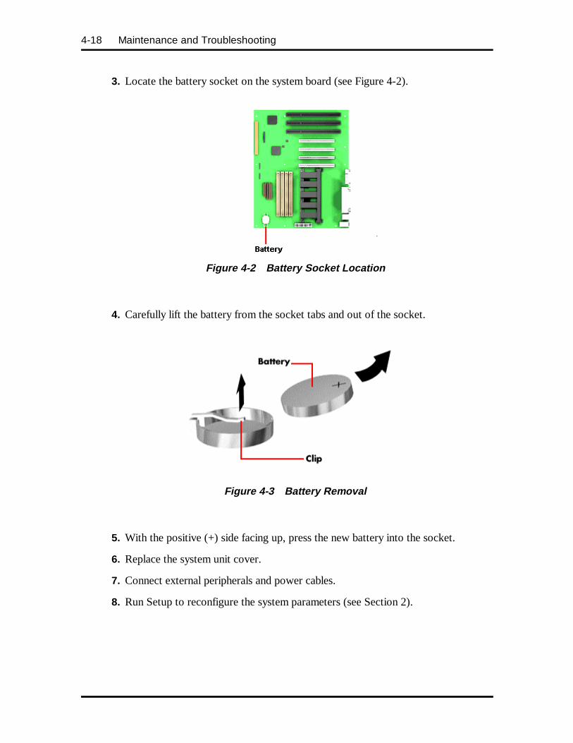
4-18 Maintenance and Troubleshooting
3. Locate the battery socket on the system board (see Figure 4-2).
Figure 4-2 Battery Socket Location
4. Carefully lift the battery from the socket tabs and out of the socket.
Figure 4-3 Battery Removal
5. With the positive (+) side facing up, press the new battery into the socket.
6. Replace the system unit cover.
7. Connect external peripherals and power cables.
8. Run Setup to reconfigure the system parameters (see Section 2).
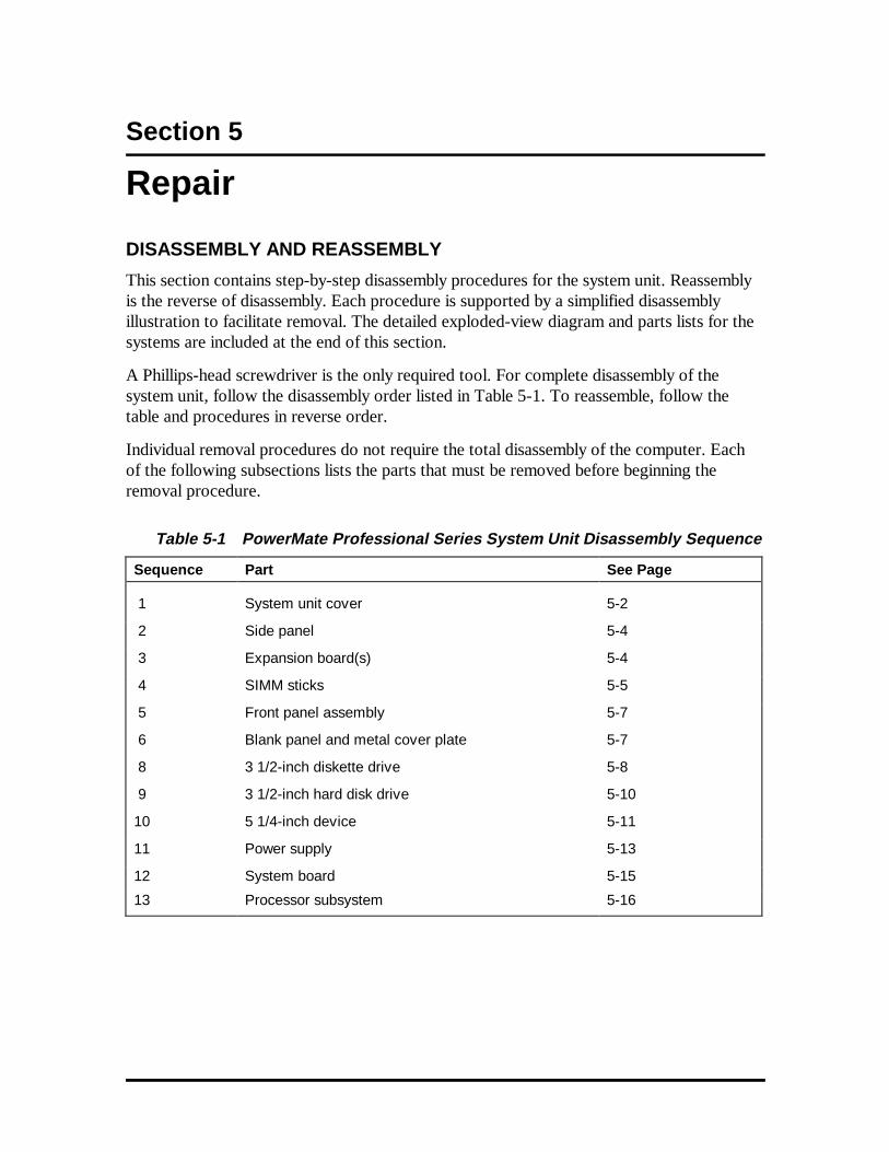
Section 5
Repair
DISASSEMBLY AND REASSEMBLY
This section contains step-by-step disassembly procedures for the system unit. Reassemblyis the reverse of disassembly. Each procedure is supported by a simplified disassemblyillustration to facilitate removal. The detailed exploded-view diagram and parts lists for thesystems are included at the end of this section.
A Phillips-head screwdriver is the only required tool. For complete disassembly of thesystem unit, follow the disassembly order listed in Table 5-1. To reassemble, follow thetable and procedures in reverse order.
Individual removal procedures do not require the total disassembly of the computer. Eachof the following subsections lists the parts that must be removed before beginning theremoval procedure.
Table 5-1 PowerMate Professional Series System Unit Disassembly Sequence
Sequence Part See Page
1 System unit cover 5-2
2 Side panel 5-4
3 Expansion board(s) 5-4
4 SIMM sticks 5-5
5 Front panel assembly 5-7
6 Blank panel and metal cover plate 5-7
8 3 1/2-inch diskette drive 5-8
9 3 1/2-inch hard disk drive 5-10
10 5 1/4-inch device 5-11
11 Power supply 5-13
12 System board 5-15
13 Processor subsystem 5-16
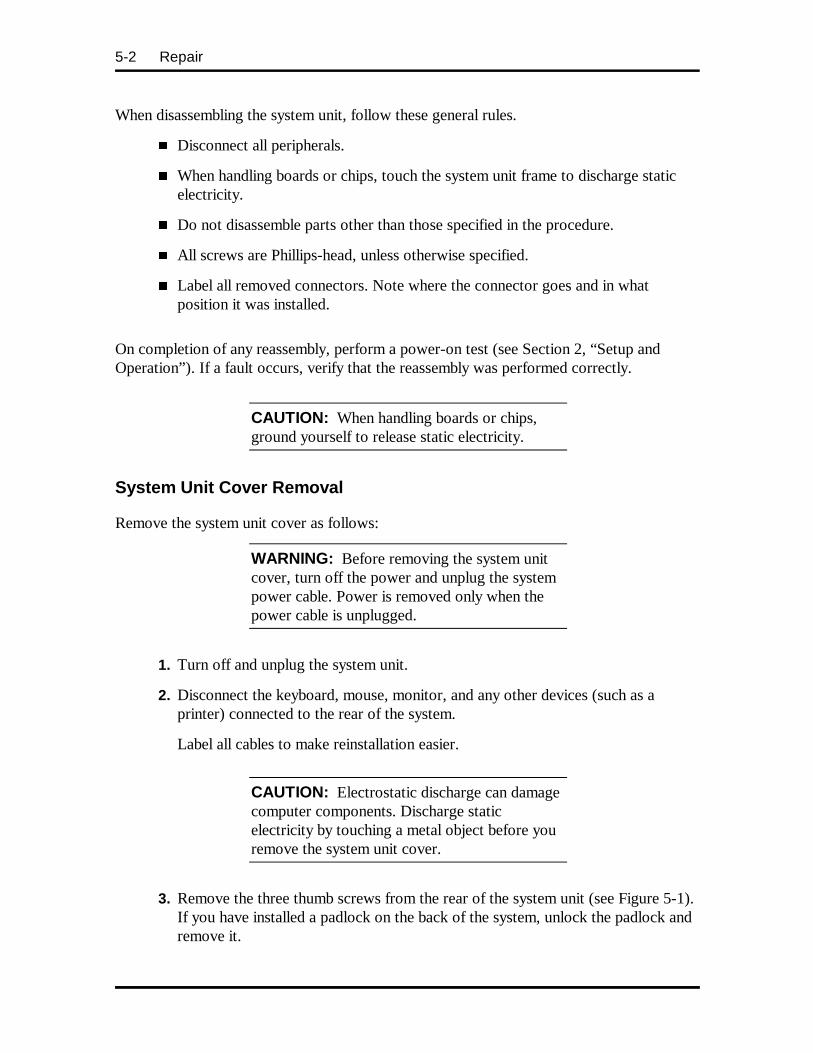
5-2 Repair
When disassembling the system unit, follow these general rules.
� Disconnect all peripherals.
� When handling boards or chips, touch the system unit frame to discharge staticelectricity.
� Do not disassemble parts other than those specified in the procedure.
� All screws are Phillips-head, unless otherwise specified.
� Label all removed connectors. Note where the connector goes and in whatposition it was installed.
On completion of any reassembly, perform a power-on test (see Section 2, “Setup andOperation”). If a fault occurs, verify that the reassembly was performed correctly.
CAUTION: When handling boards or chips,ground yourself to release static electricity.
System Unit Cover Removal
Remove the system unit cover as follows:
WARNING: Before removing the system unitcover, turn off the power and unplug the systempower cable. Power is removed only when thepower cable is unplugged.
1. Turn off and unplug the system unit.
2. Disconnect the keyboard, mouse, monitor, and any other devices (such as aprinter) connected to the rear of the system.
Label all cables to make reinstallation easier.
CAUTION: Electrostatic discharge can damagecomputer components. Discharge staticelectricity by touching a metal object before youremove the system unit cover.
3. Remove the three thumb screws from the rear of the system unit (see Figure 5-1).If you have installed a padlock on the back of the system, unlock the padlock andremove it.
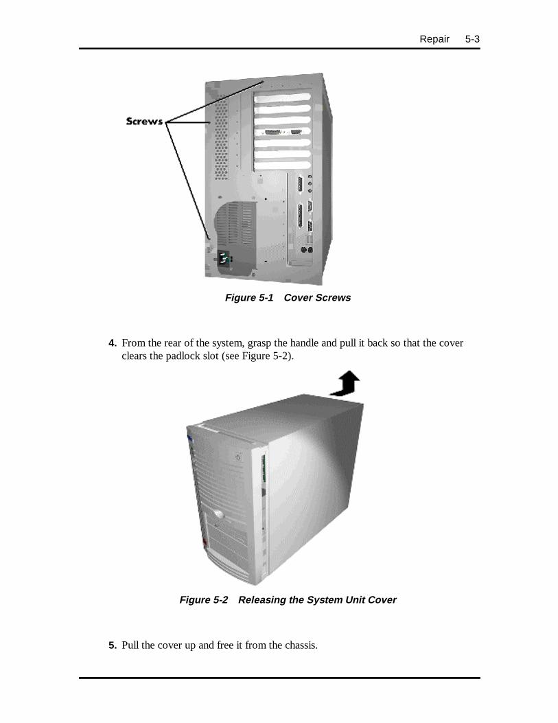
Repair 5-3
Figure 5-1 Cover Screws
4. From the rear of the system, grasp the handle and pull it back so that the coverclears the padlock slot (see Figure 5-2).
Figure 5-2 Releasing the System Unit Cover
5. Pull the cover up and free it from the chassis.
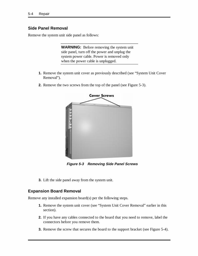
5-4 Repair
Side Panel Removal
Remove the system unit side panel as follows:
WARNING: Before removing the system unitside panel, turn off the power and unplug thesystem power cable. Power is removed onlywhen the power cable is unplugged.
1. Remove the system unit cover as previously described (see “System Unit CoverRemoval”).
2. Remove the two screws from the top of the panel (see Figure 5-3).
Figure 5-3 Removing Side Panel Screws
3. Lift the side panel away from the system unit.
Expansion Board Removal
Remove any installed expansion board(s) per the following steps.
1. Remove the system unit cover (see “System Unit Cover Removal” earlier in thissection).
2. If you have any cables connected to the board that you need to remove, label theconnectors before you remove them.
3. Remove the screw that secures the board to the support bracket (see Figure 5-4).
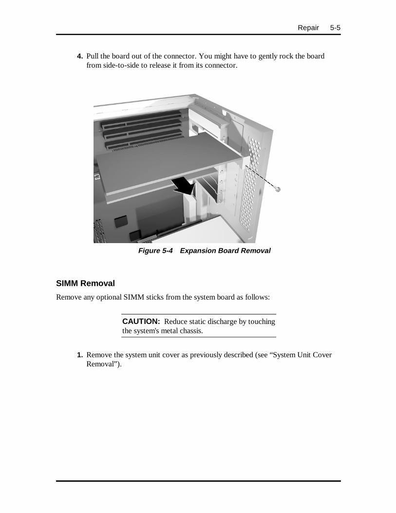
Repair 5-5
4. Pull the board out of the connector. You might have to gently rock the boardfrom side-to-side to release it from its connector.
Figure 5-4 Expansion Board Removal
SIMM Removal
Remove any optional SIMM sticks from the system board as follows:
CAUTION: Reduce static discharge by touchingthe system's metal chassis.
1. Remove the system unit cover as previously described (see “System Unit CoverRemoval”).
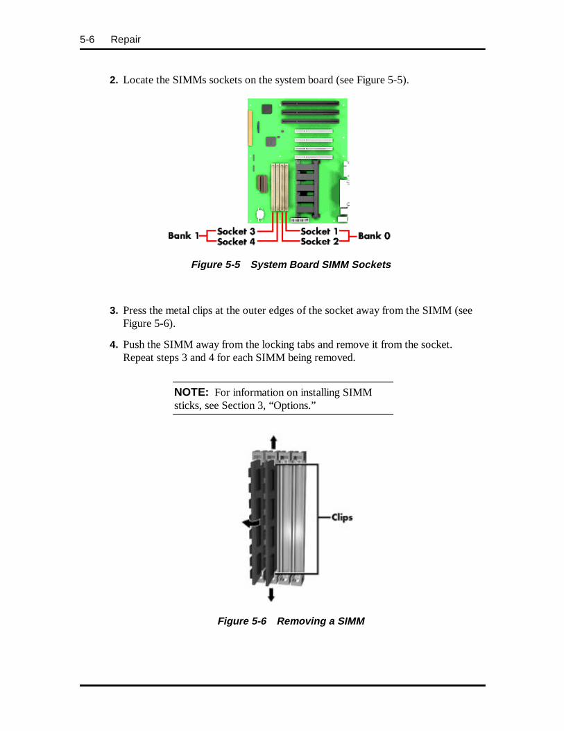
5-6 Repair
2. Locate the SIMMs sockets on the system board (see Figure 5-5).
Figure 5-5 System Board SIMM Sockets
3. Press the metal clips at the outer edges of the socket away from the SIMM (seeFigure 5-6).
4. Push the SIMM away from the locking tabs and remove it from the socket.Repeat steps 3 and 4 for each SIMM being removed.
NOTE: For information on installing SIMMsticks, see Section 3, “Options.”
Figure 5-6 Removing a SIMM
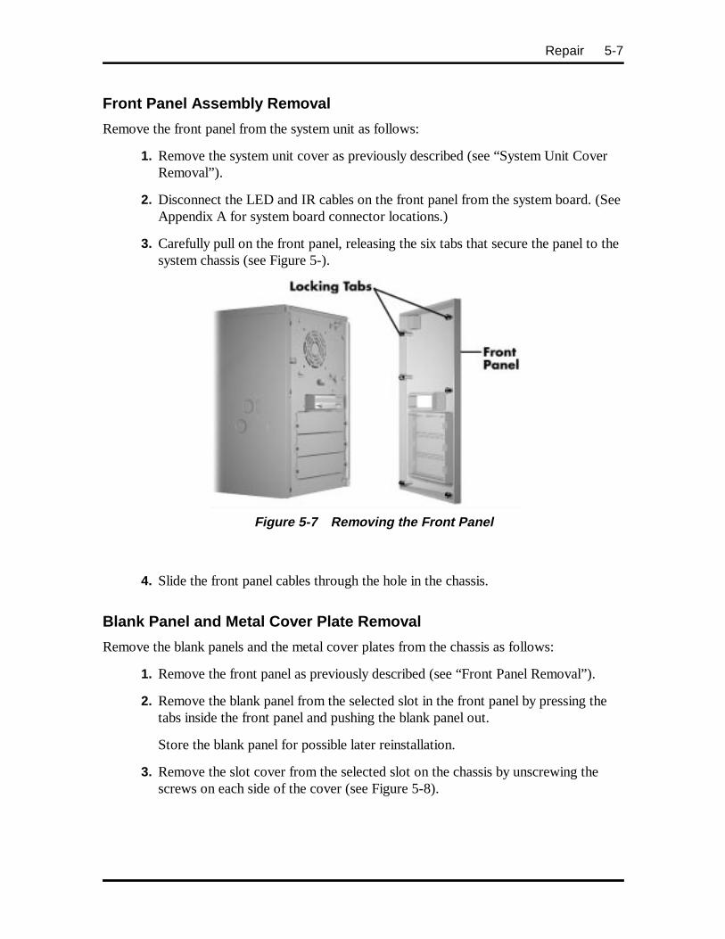
Repair 5-7
Front Panel Assembly Removal
Remove the front panel from the system unit as follows:
1. Remove the system unit cover as previously described (see “System Unit CoverRemoval”).
2. Disconnect the LED and IR cables on the front panel from the system board. (SeeAppendix A for system board connector locations.)
3. Carefully pull on the front panel, releasing the six tabs that secure the panel to thesystem chassis (see Figure 5-).
Figure 5-7 Removing the Front Panel
4. Slide the front panel cables through the hole in the chassis.
Blank Panel and Metal Cover Plate Removal
Remove the blank panels and the metal cover plates from the chassis as follows:
1. Remove the front panel as previously described (see “Front Panel Removal”).
2. Remove the blank panel from the selected slot in the front panel by pressing thetabs inside the front panel and pushing the blank panel out.
Store the blank panel for possible later reinstallation.
3. Remove the slot cover from the selected slot on the chassis by unscrewing thescrews on each side of the cover (see Figure 5-8).
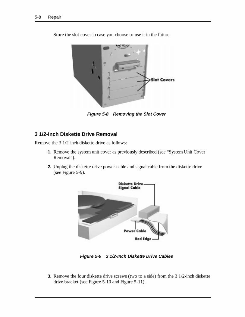
5-8 Repair
Store the slot cover in case you choose to use it in the future.
Figure 5-8 Removing the Slot Cover
3 1/2-Inch Diskette Drive Removal
Remove the 3 1/2-inch diskette drive as follows:
1. Remove the system unit cover as previously described (see “System Unit CoverRemoval”).
2. Unplug the diskette drive power cable and signal cable from the diskette drive(see Figure 5-9).
Figure 5-9 3 1/2-Inch Diskette Drive Cables
3. Remove the four diskette drive screws (two to a side) from the 3 1/2-inch diskettedrive bracket (see Figure 5-10 and Figure 5-11).
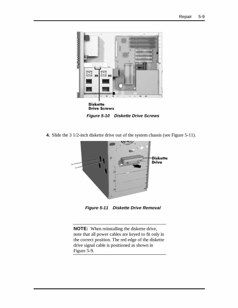
Repair 5-9
Figure 5-10 Diskette Drive Screws
4. Slide the 3 1/2-inch diskette drive out of the system chassis (see Figure 5-11).
Figure 5-11 Diskette Drive Removal
NOTE: When reinstalling the diskette drive,note that all power cables are keyed to fit only inthe correct position. The red edge of the diskettedrive signal cable is positioned as shown inFigure 5-9.
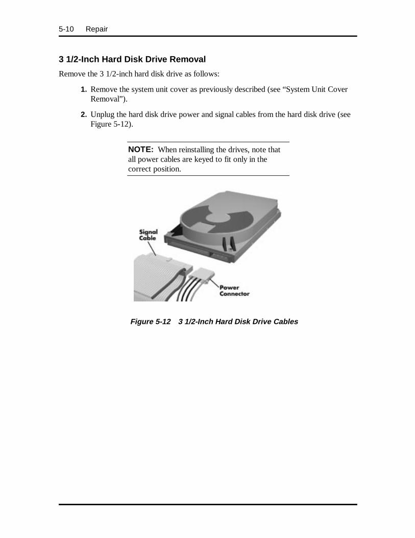
5-10 Repair
3 1/2-Inch Hard Disk Drive Removal
Remove the 3 1/2-inch hard disk drive as follows:
1. Remove the system unit cover as previously described (see “System Unit CoverRemoval”).
2. Unplug the hard disk drive power and signal cables from the hard disk drive (seeFigure 5-12).
NOTE: When reinstalling the drives, note thatall power cables are keyed to fit only in thecorrect position.
Figure 5-12 3 1/2-Inch Hard Disk Drive Cables
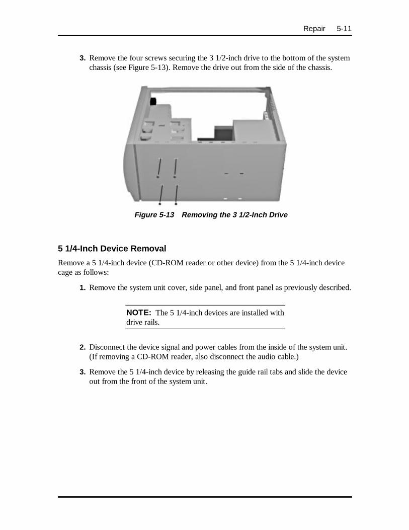
Repair 5-11
3. Remove the four screws securing the 3 1/2-inch drive to the bottom of the systemchassis (see Figure 5-13). Remove the drive out from the side of the chassis.
Figure 5-13 Removing the 3 1/2-Inch Drive
5 1/4-Inch Device Removal
Remove a 5 1/4-inch device (CD-ROM reader or other device) from the 5 1/4-inch devicecage as follows:
1. Remove the system unit cover, side panel, and front panel as previously described.
NOTE: The 5 1/4-inch devices are installed withdrive rails.
2. Disconnect the device signal and power cables from the inside of the system unit.(If removing a CD-ROM reader, also disconnect the audio cable.)
3. Remove the 5 1/4-inch device by releasing the guide rail tabs and slide the deviceout from the front of the system unit.
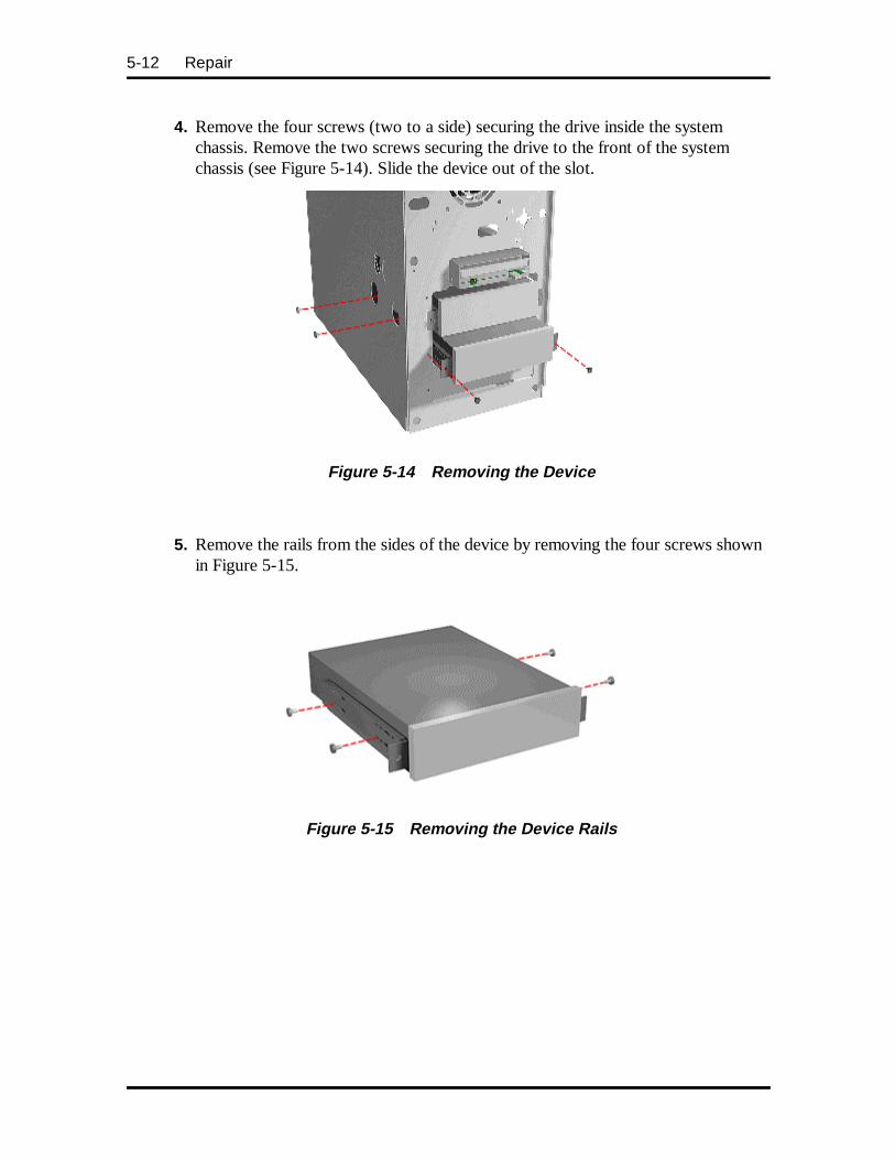
5-12 Repair
4. Remove the four screws (two to a side) securing the drive inside the systemchassis. Remove the two screws securing the drive to the front of the systemchassis (see Figure 5-14). Slide the device out of the slot.
Figure 5-14 Removing the Device
5. Remove the rails from the sides of the device by removing the four screws shownin Figure 5-15.
Figure 5-15 Removing the Device Rails
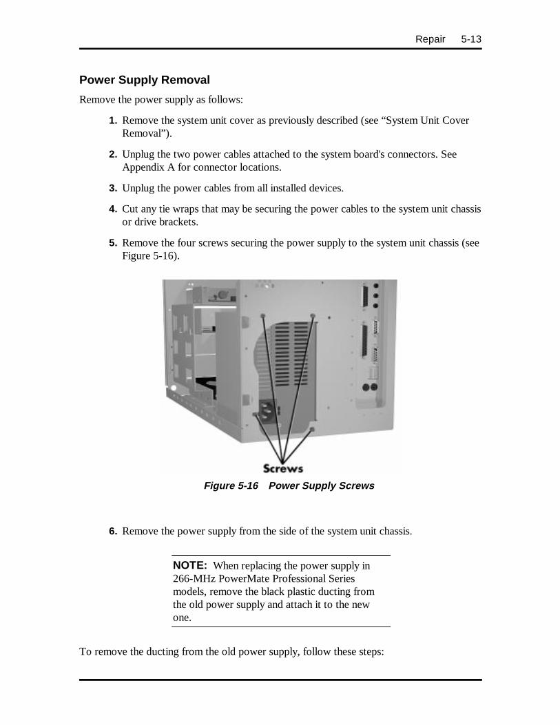
Repair 5-13
Power Supply Removal
Remove the power supply as follows:
1. Remove the system unit cover as previously described (see “System Unit CoverRemoval”).
2. Unplug the two power cables attached to the system board's connectors. SeeAppendix A for connector locations.
3. Unplug the power cables from all installed devices.
4. Cut any tie wraps that may be securing the power cables to the system unit chassisor drive brackets.
5. Remove the four screws securing the power supply to the system unit chassis (seeFigure 5-16).
Figure 5-16 Power Supply Screws
6. Remove the power supply from the side of the system unit chassis.
NOTE: When replacing the power supply in266-MHz PowerMate Professional Seriesmodels, remove the black plastic ducting fromthe old power supply and attach it to the newone.
To remove the ducting from the old power supply, follow these steps:
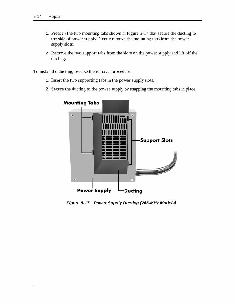
5-14 Repair
1. Press in the two mounting tabs shown in Figure 5-17 that secure the ducting tothe side of power supply. Gently remove the mounting tabs from the powersupply slots.
2. Remove the two support tabs from the slots on the power supply and lift off theducting.
To install the ducting, reverse the removal procedure:
1. Insert the two supporting tabs in the power supply slots.
2. Secure the ducting to the power supply by snapping the mounting tabs in place.
Figure 5-17 Power Supply Ducting ( 266-MHz Models)
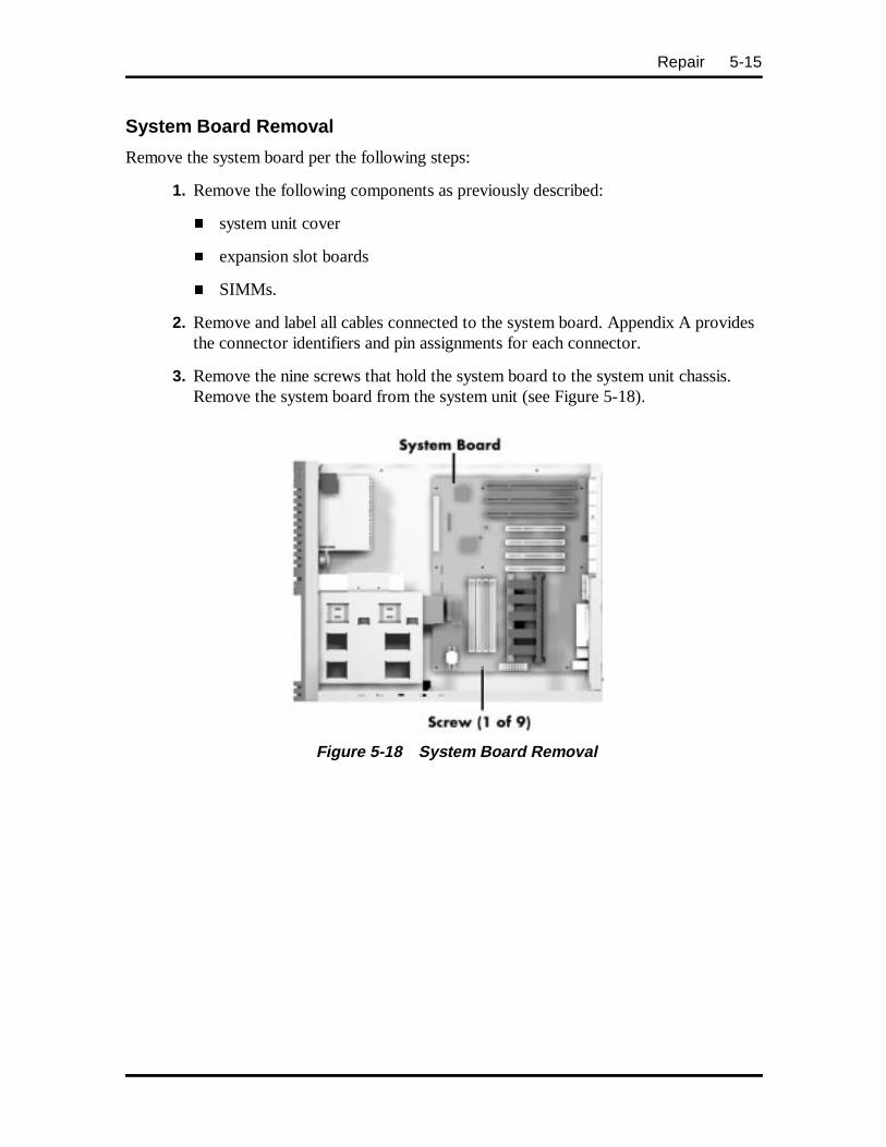
Repair 5-15
System Board Removal
Remove the system board per the following steps:
1. Remove the following components as previously described:
� system unit cover
� expansion slot boards
� SIMMs.
2. Remove and label all cables connected to the system board. Appendix A providesthe connector identifiers and pin assignments for each connector.
3. Remove the nine screws that hold the system board to the system unit chassis.Remove the system board from the system unit (see Figure 5-18).
Figure 5-18 System Board Removal
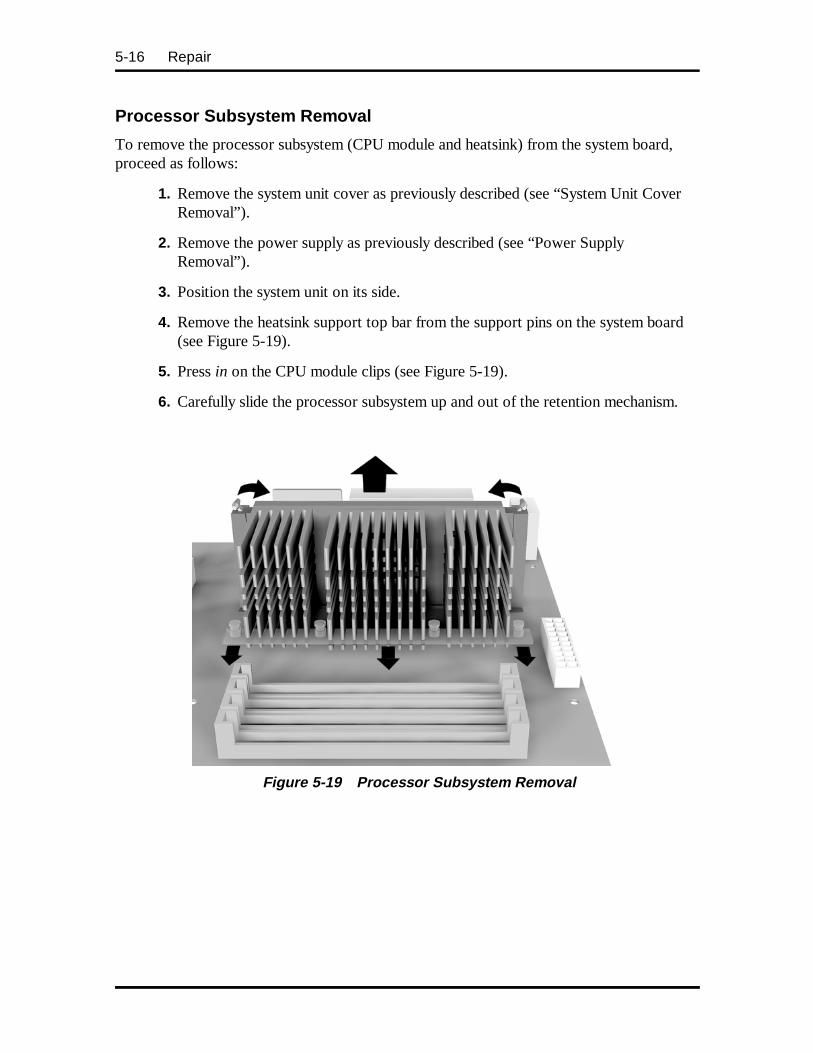
5-16 Repair
Processor Subsystem Removal
To remove the processor subsystem (CPU module and heatsink) from the system board,proceed as follows:
1. Remove the system unit cover as previously described (see “System Unit CoverRemoval”).
2. Remove the power supply as previously described (see “Power SupplyRemoval”).
3. Position the system unit on its side.
4. Remove the heatsink support top bar from the support pins on the system board(see Figure 5-19).
5. Press in on the CPU module clips (see Figure 5-19).
6. Carefully slide the processor subsystem up and out of the retention mechanism.
Figure 5-19 Processor Subsystem Removal
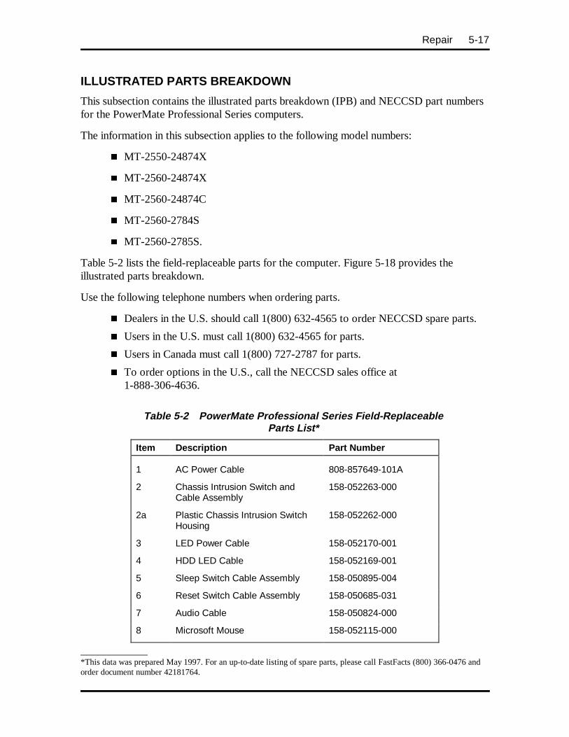
Repair 5-17
ILLUSTRATED PARTS BREAKDOWN
This subsection contains the illustrated parts breakdown (IPB) and NECCSD part numbersfor the PowerMate Professional Series computers.
The information in this subsection applies to the following model numbers:
� MT-2550-24874X
� MT-2560-24874X
� MT-2560-24874C
� MT-2560-2784S
� MT-2560-2785S.
Table 5-2 lists the field-replaceable parts for the computer. Figure 5-18 provides theillustrated parts breakdown.
Use the following telephone numbers when ordering parts.
� Dealers in the U.S. should call 1(800) 632-4565 to order NECCSD spare parts.
� Users in the U.S. must call 1(800) 632-4565 for parts.
� Users in Canada must call 1(800) 727-2787 for parts.
� To order options in the U.S., call the NECCSD sales office at1-888-306-4636.
Table 5-2 PowerMate Professional Series Field-ReplaceableParts List*
Item Description Part Number
1 AC Power Cable 808-857649-101A
2 Chassis Intrusion Switch andCable Assembly
158-052263-000
2a Plastic Chassis Intrusion SwitchHousing
158-052262-000
3 LED Power Cable 158-052170-001
4 HDD LED Cable 158-052169-001
5 Sleep Switch Cable Assembly 158-050895-004
6 Reset Switch Cable Assembly 158-050685-031
7 Audio Cable 158-050824-000
8 Microsoft Mouse 158-052115-000
____________*This data was prepared May 1997. For an up-to-date listing of spare parts, please call FastFacts (800) 366-0476 andorder document number 42181764.
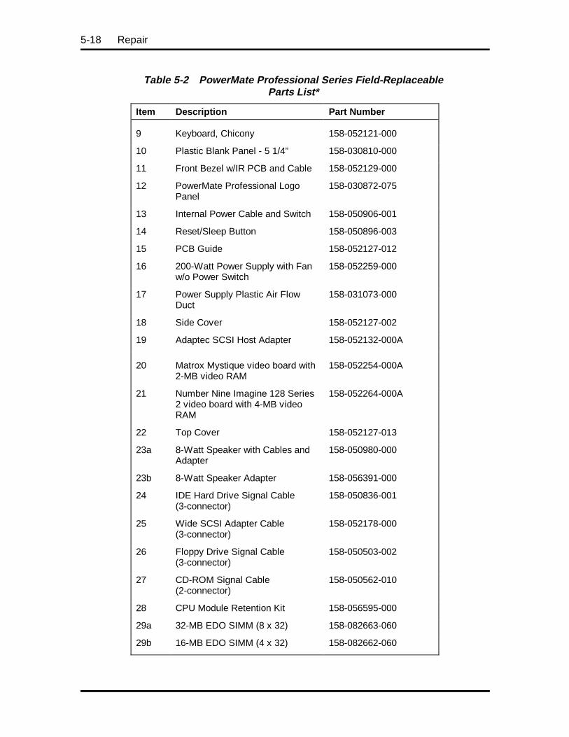
5-18 Repair
Table 5-2 PowerMate Professional Series Field-ReplaceableParts List*
Item Description Part Number
9 Keyboard, Chicony 158-052121-000
10 Plastic Blank Panel - 5 1/4” 158-030810-000
11 Front Bezel w/IR PCB and Cable 158-052129-000
12 PowerMate Professional LogoPanel
158-030872-075
13 Internal Power Cable and Switch 158-050906-001
14 Reset/Sleep Button 158-050896-003
15 PCB Guide 158-052127-012
16 200-Watt Power Supply with Fanw/o Power Switch
158-052259-000
17 Power Supply Plastic Air FlowDuct
158-031073-000
18 Side Cover 158-052127-002
19 Adaptec SCSI Host Adapter 158-052132-000A
20 Matrox Mystique video board with2-MB video RAM
158-052254-000A
21 Number Nine Imagine 128 Series2 video board with 4-MB videoRAM
158-052264-000A
22 Top Cover 158-052127-013
23a 8-Watt Speaker with Cables andAdapter
158-050980-000
23b 8-Watt Speaker Adapter 158-056391-000
24 IDE Hard Drive Signal Cable(3-connector)
158-050836-001
25 Wide SCSI Adapter Cable(3-connector)
158-052178-000
26 Floppy Drive Signal Cable(3-connector)
158-050503-002
27 CD-ROM Signal Cable(2-connector)
158-050562-010
28 CPU Module Retention Kit 158-056595-000
29a 32-MB EDO SIMM (8 x 32) 158-082663-060
29b 16-MB EDO SIMM (4 x 32) 158-082662-060
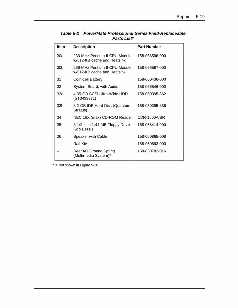
Repair 5-19
Table 5-2 PowerMate Professional Series Field-ReplaceableParts List*
Item Description Part Number
30a 233-MHz Pentium II CPU Modulew/512-KB cache and Heatsink
158-056596-000
30b 266-MHz Pentium II CPU Modulew/512-KB cache and Heatsink
158-056597-000
31 Coin-cell Battery 158-060436-000
32 System Board, with Audio 158-056546-000
33a 4.35-GB SCSI Ultra-Wide HDD(ST3433371)
158-050395-362
33b 3.2-GB IDE Hard Disk (QuantumStratus)
158-050395-386
34 NEC 16X (max) CD-ROM Reader CDR-1600A/BR
35 3-1/2 inch 1.44-MB Floppy Drive(w/o Bezel)
158-056414-000
36 Speaker with Cable 158-050865-008
-- Rail Kit* 158-050893-000
-- Rear I/O Ground Spring(Multimedia System)*
158-030782-016
* = Not shown in Figure 5-20
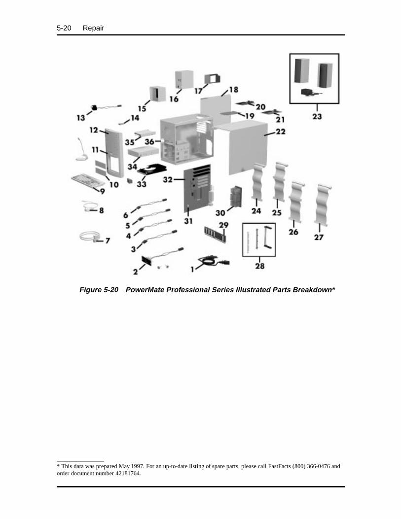
5-20 Repair
Figure 5-20 PowerMate Professional Series Illustrated Parts Breakdown*
____________* This data was prepared May 1997. For an up-to-date listing of spare parts, please call FastFacts (800) 366-0476 andorder document number 42181764.
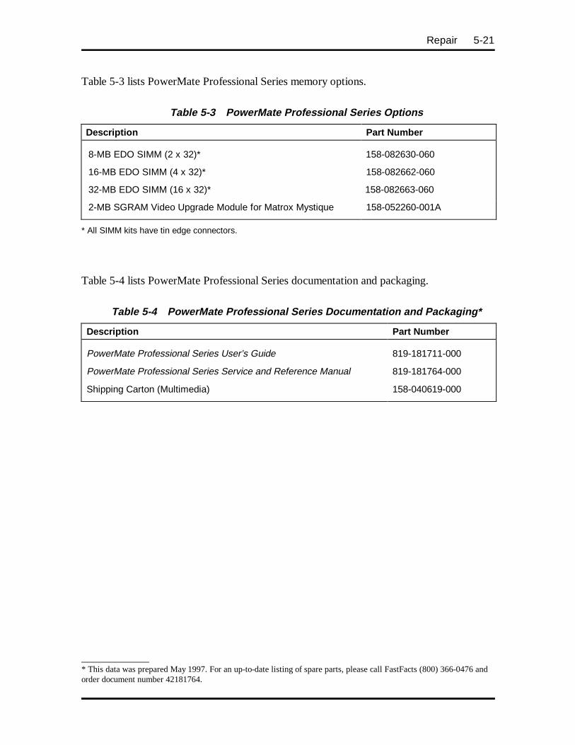
Repair 5-21
Table 5-3 lists PowerMate Professional Series memory options.
Table 5-3 PowerMate Professional Series Options
Description Part Number
8-MB EDO SIMM (2 x 32)* 158-082630-060
16-MB EDO SIMM (4 x 32)* 158-082662-060
32-MB EDO SIMM (16 x 32)* 158-082663-060
2-MB SGRAM Video Upgrade Module for Matrox Mystique 158-052260-001A
* All SIMM kits have tin edge connectors.
Table 5-4 lists PowerMate Professional Series documentation and packaging.
Table 5-4 PowerMate Professional Series Documentation and Packaging*
Description Part Number
PowerMate Professional Series User’s Guide 819-181711-000
PowerMate Professional Series Service and Reference Manual 819-181764-000
Shipping Carton (Multimedia) 158-040619-000
____________* This data was prepared May 1997. For an up-to-date listing of spare parts, please call FastFacts (800) 366-0476 andorder document number 42181764.
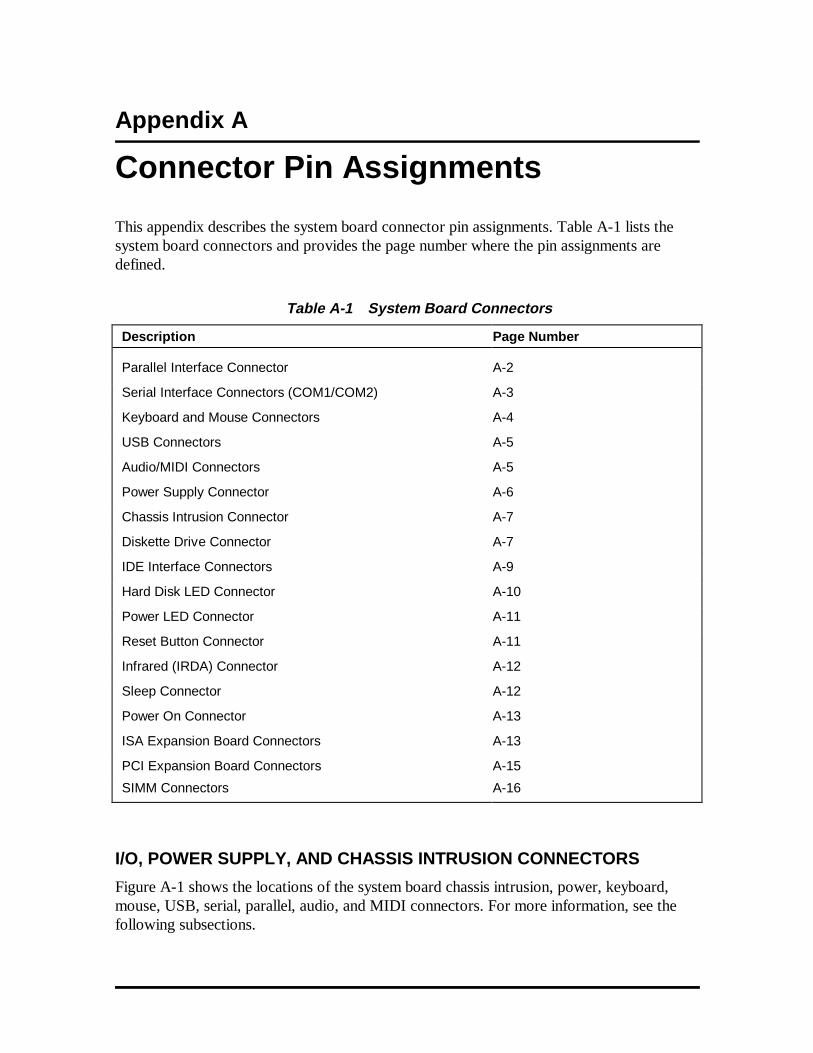
Appendix A
Connector Pin Assignments
This appendix describes the system board connector pin assignments. Table A-1 lists thesystem board connectors and provides the page number where the pin assignments aredefined.
Table A-1 System Board Connectors
Description Page Number
Parallel Interface Connector A-2
Serial Interface Connectors (COM1/COM2) A-3
Keyboard and Mouse Connectors A-4
USB Connectors A-5
Audio/MIDI Connectors A-5
Power Supply Connector A-6
Chassis Intrusion Connector A-7
Diskette Drive Connector A-7
IDE Interface Connectors A-9
Hard Disk LED Connector A-10
Power LED Connector A-11
Reset Button Connector A-11
Infrared (IRDA) Connector A-12
Sleep Connector A-12
Power On Connector A-13
ISA Expansion Board Connectors A-13
PCI Expansion Board Connectors A-15
SIMM Connectors A-16
I/O, POWER SUPPLY, AND CHASSIS INTRUSION CONNECTORS
Figure A-1 shows the locations of the system board chassis intrusion, power, keyboard,mouse, USB, serial, parallel, audio, and MIDI connectors. For more information, see thefollowing subsections.
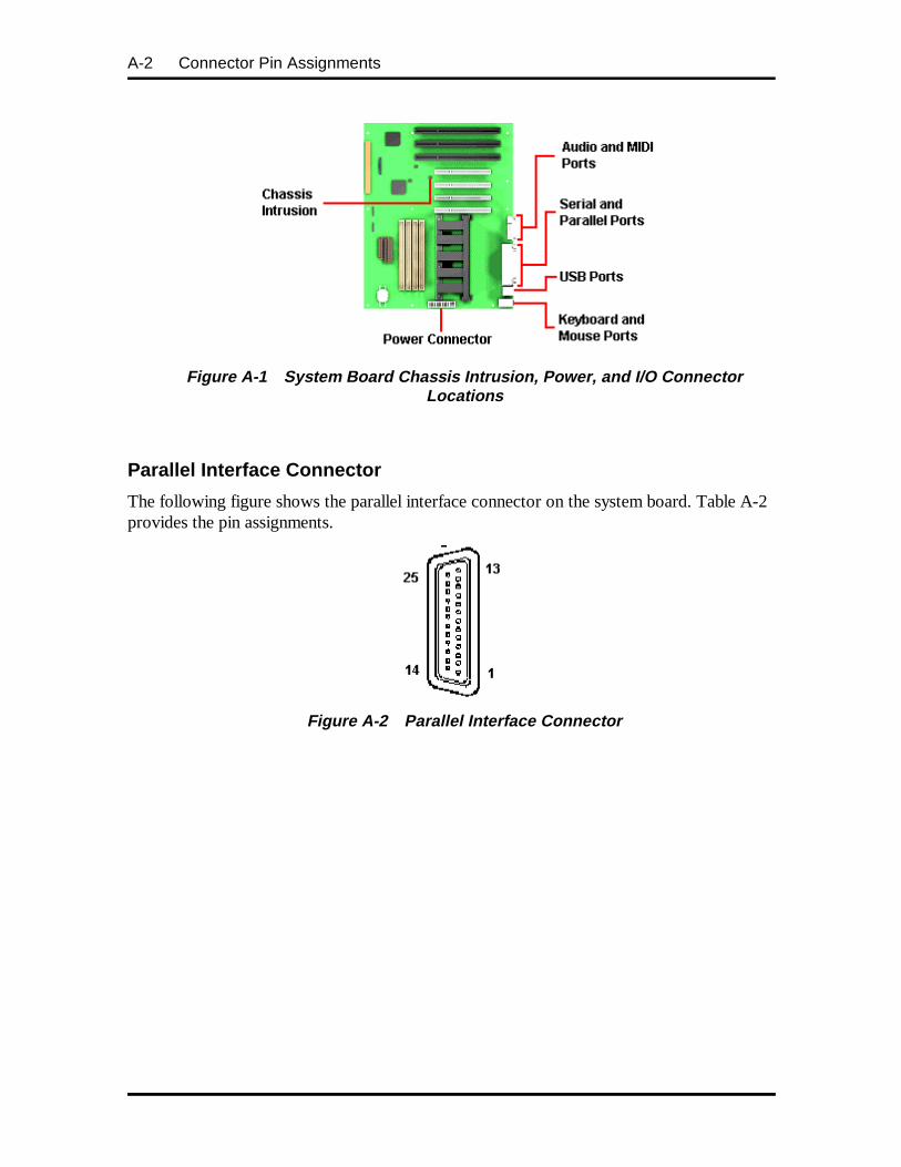
A-2 Connector Pin Assignments
Figure A-1 System Board Chassis Intrusion, Power, and I/O ConnectorLocations
Parallel Interface Connector
The following figure shows the parallel interface connector on the system board. Table A-2provides the pin assignments.
Figure A-2 Parallel Interface C onnector
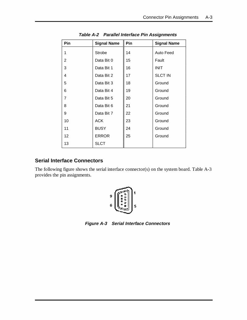
Connector Pin Assignments A-3
Table A-2 Parallel Interface Pin Assignments
Pin Signal Name Pin Signal Name
1 Strobe 14 Auto Feed
2 Data Bit 0 15 Fault
3 Data Bit 1 16 INIT
4 Data Bit 2 17 SLCT IN
5 Data Bit 3 18 Ground
6 Data Bit 4 19 Ground
7 Data Bit 5 20 Ground
8 Data Bit 6 21 Ground
9 Data Bit 7 22 Ground
10 ACK 23 Ground
11 BUSY 24 Ground
12 ERROR 25 Ground
13 SLCT
Serial Interface Connectors
The following figure shows the serial interface connector(s) on the system board. Table A-3provides the pin assignments.
Figure A-3 Serial Interface C onnectors
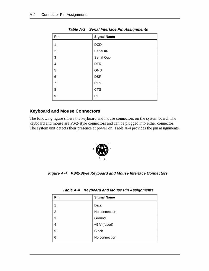
A-4 Connector Pin Assignments
Table A-3 Serial Interface Pin Assignments
Pin Signal Name
1 DCD
2 Serial In-
3 Serial Out-
4 DTR
5 GND
6 DSR
7 RTS
8 CTS
9 RI
Keyboard and Mouse Connectors
The following figure shows the keyboard and mouse connectors on the system board. Thekeyboard and mouse are PS/2-style connectors and can be plugged into either connector.The system unit detects their presence at power on. Table A-4 provides the pin assignments.
Figure A-4 PS/2-Style Keyboard and Mouse Interface C onnectors
Table A-4 Keyboard and Mouse Pin Assignments
Pin Signal Name
1 Data
2 No connection
3 Ground
4 +5 V (fused)
5 Clock
6 No connection
12
6
4 3
5
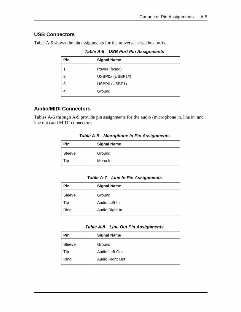
Connector Pin Assignments A-5
USB Connectors
Table A-5 shows the pin assignments for the universal serial bus ports.
Table A-5 USB Port Pin Assignments
Pin Signal Name
1 Power (fused)
2 USBP0# (USBP1#)
3 USBP0 (USBP1)
4 Ground
Audio/MIDI Connectors
Tables A-6 through A-9 provide pin assignments for the audio (microphone in, line in, andline out) and MIDI connectors.
Table A-6 Microphone In Pin Assignments
Pin Signal Name
Sleeve Ground
Tip Mono In
Table A-7 Line In Pin Assignments
Pin Signal Name
Sleeve Ground
Tip Audio Left In
Ring Audio Right In
Table A-8 Line Out Pin Assignments
Pin Signal Name
Sleeve Ground
Tip Audio Left Out
Ring Audio Right Out
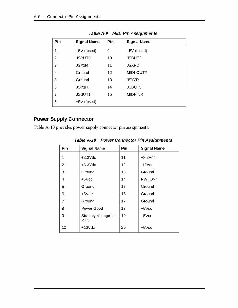
A-6 Connector Pin Assignments
Table A-9 MIDI Pin Assignments
Pin Signal Name Pin Signal Name
1 +5V (fused) 9 +5V (fused)
2 JSBUTO 10 JSBUT2
3 JSX1R 11 JSXR2
4 Ground 12 MIDI-OUTR
5 Ground 13 JSY2R
6 JSY1R 14 JSBUT3
7 JSBUT1 15 MIDI-INR
8 +5V (fused)
Power Supply Connector
Table A-10 provides power supply connector pin assignments.
Table A-10 Power Connector Pin Assignments
Pin Signal Name Pin Signal Name
1 +3.3Vdc 11 +3.3Vdc
2 +3.3Vdc 12 -12Vdc
3 Ground 13 Ground
4 +5Vdc 14 PW_ON#
5 Ground 15 Ground
6 +5Vdc 16 Ground
7 Ground 17 Ground
8 Power Good 18 +5Vdc
9 Standby Voltage forRTC
19 +5Vdc
10 +12Vdc 20 +5Vdc
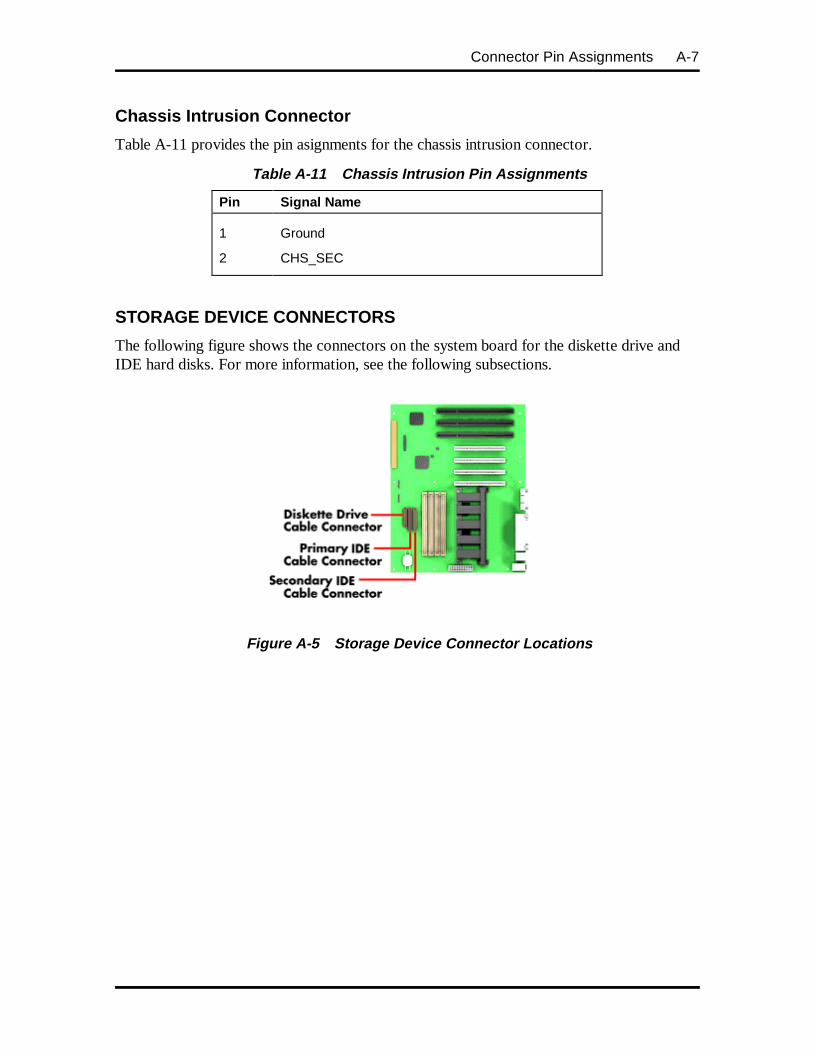
Connector Pin Assignments A-7
Chassis Intrusion Connector
Table A-11 provides the pin asignments for the chassis intrusion connector.
Table A-11 Chassis Intrusion Pin Assignments
Pin Signal Name
1 Ground
2 CHS_SEC
STORAGE DEVICE CONNECTORS
The following figure shows the connectors on the system board for the diskette drive andIDE hard disks. For more information, see the following subsections.
Figure A-5 Storage Device Connector Locations
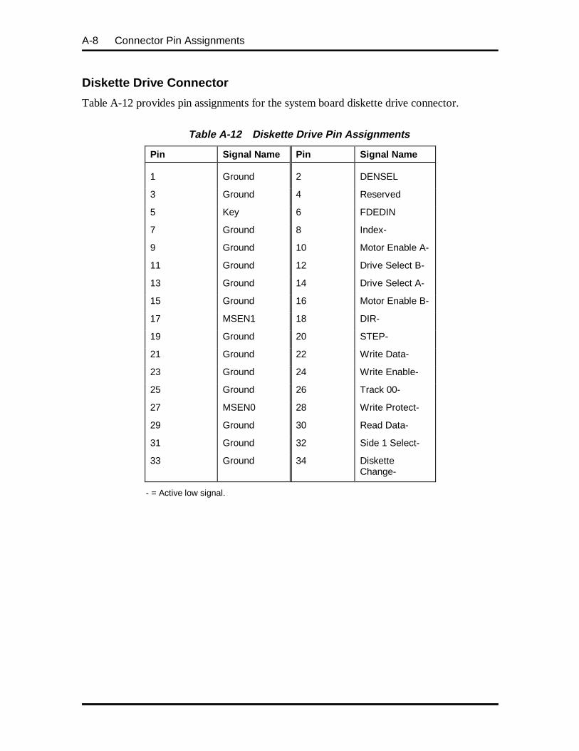
A-8 Connector Pin Assignments
Diskette Drive Connector
Table A-12 provides pin assignments for the system board diskette drive connector.
Table A-12 Diskette Drive Pin Assignments
Pin Signal Name Pin Signal Name
1 Ground 2 DENSEL
3 Ground 4 Reserved
5 Key 6 FDEDIN
7 Ground 8 Index-
9 Ground 10 Motor Enable A-
11 Ground 12 Drive Select B-
13 Ground 14 Drive Select A-
15 Ground 16 Motor Enable B-
17 MSEN1 18 DIR-
19 Ground 20 STEP-
21 Ground 22 Write Data-
23 Ground 24 Write Enable-
25 Ground 26 Track 00-
27 MSEN0 28 Write Protect-
29 Ground 30 Read Data-
31 Ground 32 Side 1 Select-
33 Ground 34 DisketteChange-
- = Active low signal.
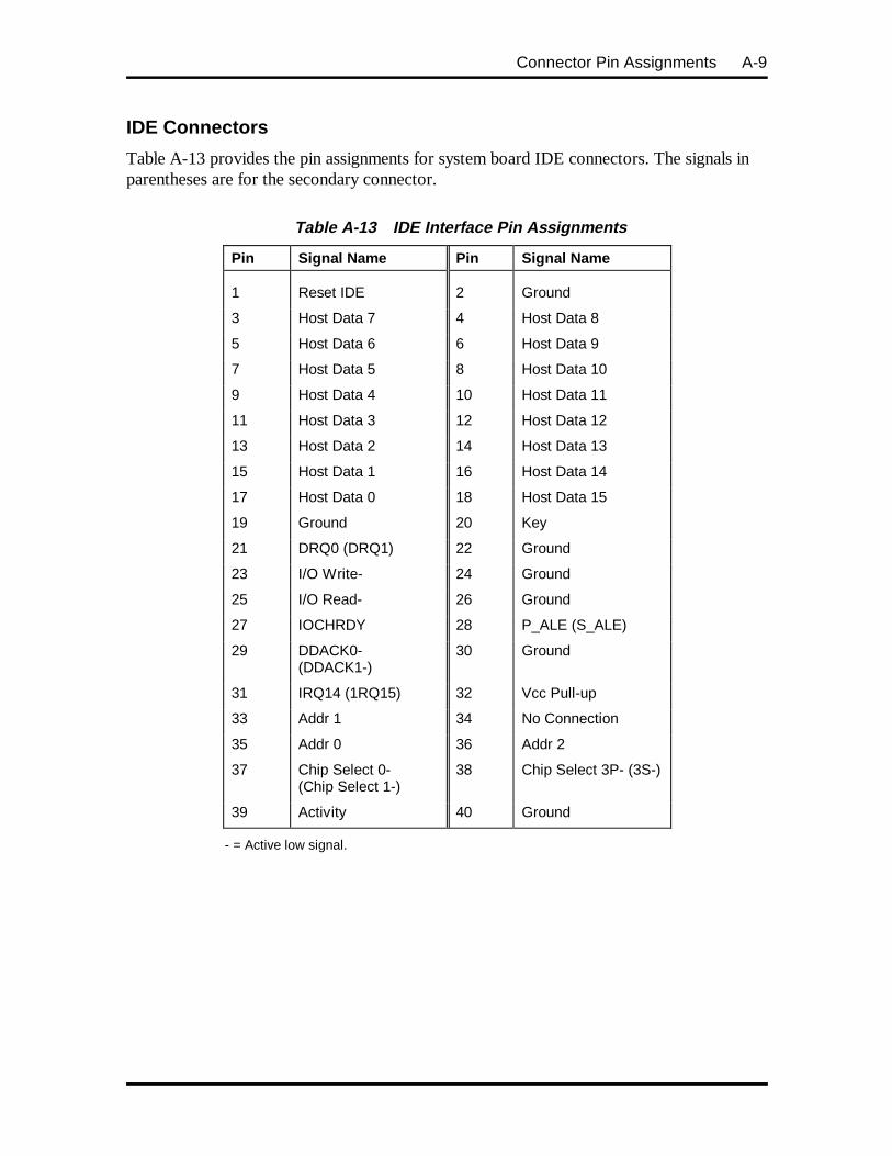
Connector Pin Assignments A-9
IDE Connectors
Table A-13 provides the pin assignments for system board IDE connectors. The signals inparentheses are for the secondary connector.
Table A-13 IDE Interface Pin Assignments
Pin Signal Name Pin Signal Name
1 Reset IDE 2 Ground
3 Host Data 7 4 Host Data 8
5 Host Data 6 6 Host Data 9
7 Host Data 5 8 Host Data 10
9 Host Data 4 10 Host Data 11
11 Host Data 3 12 Host Data 12
13 Host Data 2 14 Host Data 13
15 Host Data 1 16 Host Data 14
17 Host Data 0 18 Host Data 15
19 Ground 20 Key
21 DRQ0 (DRQ1) 22 Ground
23 I/O Write- 24 Ground
25 I/O Read- 26 Ground
27 IOCHRDY 28 P_ALE (S_ALE)
29 DDACK0-(DDACK1-)
30 Ground
31 IRQ14 (1RQ15) 32 Vcc Pull-up
33 Addr 1 34 No Connection
35 Addr 0 36 Addr 2
37 Chip Select 0-(Chip Select 1-)
38 Chip Select 3P- (3S-)
39 Activity 40 Ground
- = Active low signal.
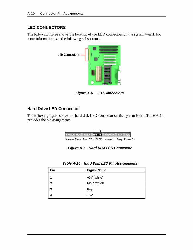
A-10 Connector Pin Assignments
LED CONNECTORS
The following figure shows the location of the LED connectors on the system board. Formore information, see the following subsections.
Figure A-6 LED Connectors
Hard Drive LED Connector
The following figure shows the hard disk LED connector on the system board. Table A-14provides the pin assignments.
Figure A-7 Hard Disk LED Connector
Table A-14 Hard Disk LED Pin Assignments
Pin Signal Name
1 +5V (white)
2 HD ACTIVE
3 Key
4 +5V
1 4
Speaker HDLED InfraredReset Pwr LED Sleep Power On
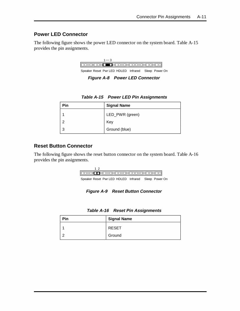
Connector Pin Assignments A-11
Power LED Connector
The following figure shows the power LED connector on the system board. Table A-15provides the pin assignments.
Figure A-8 Power LED Connector
Table A-15 Power LED Pin Assignments
Pin Signal Name
1 LED_PWR (green)
2 Key
3 Ground (blue)
Reset Button Connector
The following figure shows the reset button connector on the system board. Table A-16provides the pin assignments.
Figure A-9 Reset Button Connector
Table A-16 Reset Pin Assignments
Pin Signal Name
1 RESET
2 Ground
1 3
Speaker HDLED InfraredReset Pwr LED Sleep Power On
1 2
Speaker HDLED InfraredReset Pwr LED Sleep Power On
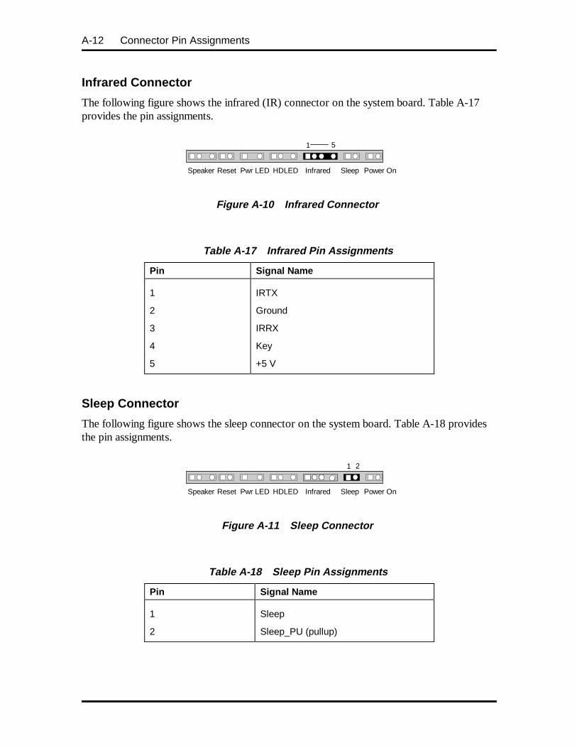
A-12 Connector Pin Assignments
Infrared Connector
The following figure shows the infrared (IR) connector on the system board. Table A-17provides the pin assignments.
Figure A-10 Infrared Connector
Table A-17 Infrared Pin Assignments
Pin Signal Name
1 IRTX
2 Ground
3 IRRX
4 Key
5 +5 V
Sleep Connector
The following figure shows the sleep connector on the system board. Table A-18 providesthe pin assignments.
Figure A-11 Sleep Connector
Table A-18 Sleep Pin Assignments
Pin Signal Name
1 Sleep
2 Sleep_PU (pullup)
1 5
Speaker HDLED InfraredReset Pwr LED Sleep Power On
1 2
Speaker HDLED InfraredReset Pwr LED Sleep Power On
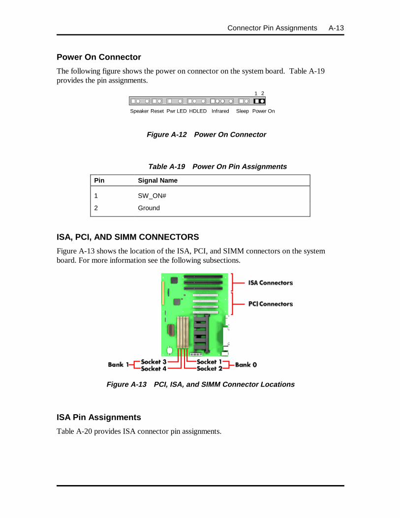
Connector Pin Assignments A-13
Power On Connector
The following figure shows the power on connector on the system board. Table A-19provides the pin assignments.
Figure A-12 Power On Connector
Table A-19 Power On Pin Assignments
Pin Signal Name
1 SW_ON#
2 Ground
ISA, PCI, AND SIMM CONNECTORS
Figure A-13 shows the location of the ISA, PCI, and SIMM connectors on the systemboard. For more information see the following subsections.
Figure A-13 PCI, ISA, and SIMM Connector Locations
ISA Pin Assignments
Table A-20 provides ISA connector pin assignments.
1 2
Speaker HDLED InfraredReset Pwr LED Sleep Power On
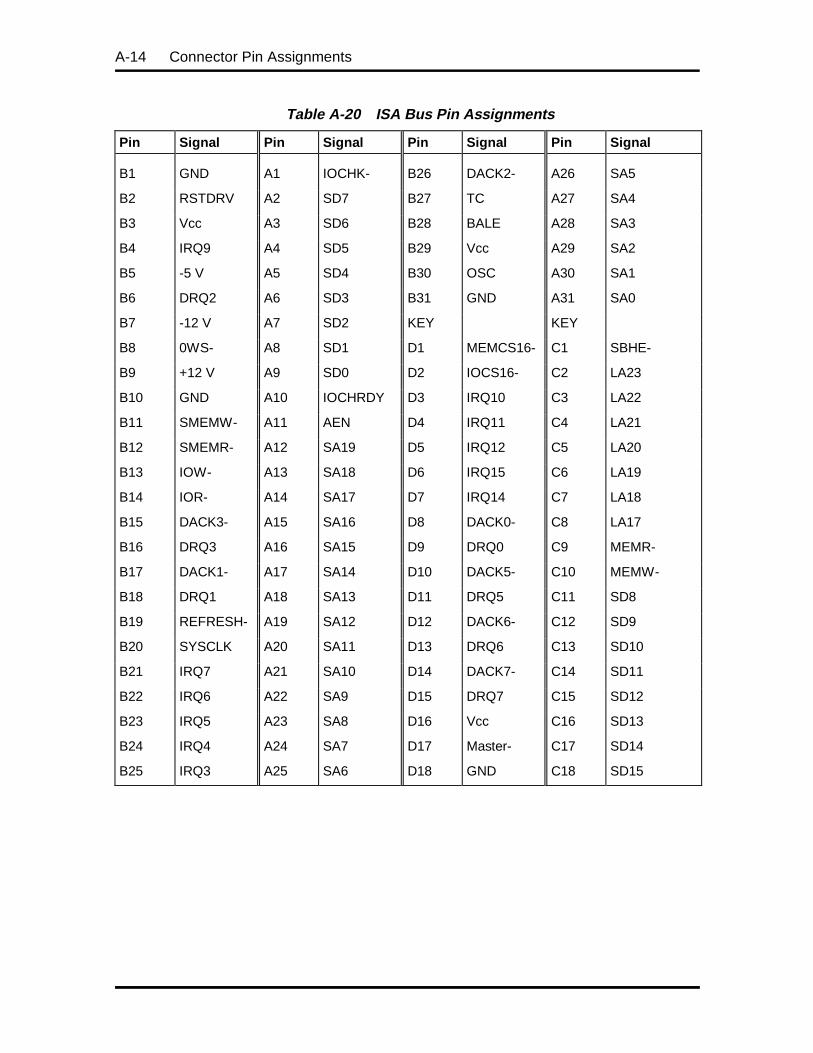
A-14 Connector Pin Assignments
Table A-20 ISA Bus Pin Assignments
Pin Signal Pin Signal Pin Signal Pin Signal
B1 GND A1 IOCHK- B26 DACK2- A26 SA5
B2 RSTDRV A2 SD7 B27 TC A27 SA4
B3 Vcc A3 SD6 B28 BALE A28 SA3
B4 IRQ9 A4 SD5 B29 Vcc A29 SA2
B5 -5 V A5 SD4 B30 OSC A30 SA1
B6 DRQ2 A6 SD3 B31 GND A31 SA0
B7 -12 V A7 SD2 KEY KEY
B8 0WS- A8 SD1 D1 MEMCS16- C1 SBHE-
B9 +12 V A9 SD0 D2 IOCS16- C2 LA23
B10 GND A10 IOCHRDY D3 IRQ10 C3 LA22
B11 SMEMW- A11 AEN D4 IRQ11 C4 LA21
B12 SMEMR- A12 SA19 D5 IRQ12 C5 LA20
B13 IOW- A13 SA18 D6 IRQ15 C6 LA19
B14 IOR- A14 SA17 D7 IRQ14 C7 LA18
B15 DACK3- A15 SA16 D8 DACK0- C8 LA17
B16 DRQ3 A16 SA15 D9 DRQ0 C9 MEMR-
B17 DACK1- A17 SA14 D10 DACK5- C10 MEMW-
B18 DRQ1 A18 SA13 D11 DRQ5 C11 SD8
B19 REFRESH- A19 SA12 D12 DACK6- C12 SD9
B20 SYSCLK A20 SA11 D13 DRQ6 C13 SD10
B21 IRQ7 A21 SA10 D14 DACK7- C14 SD11
B22 IRQ6 A22 SA9 D15 DRQ7 C15 SD12
B23 IRQ5 A23 SA8 D16 Vcc C16 SD13
B24 IRQ4 A24 SA7 D17 Master- C17 SD14
B25 IRQ3 A25 SA6 D18 GND C18 SD15
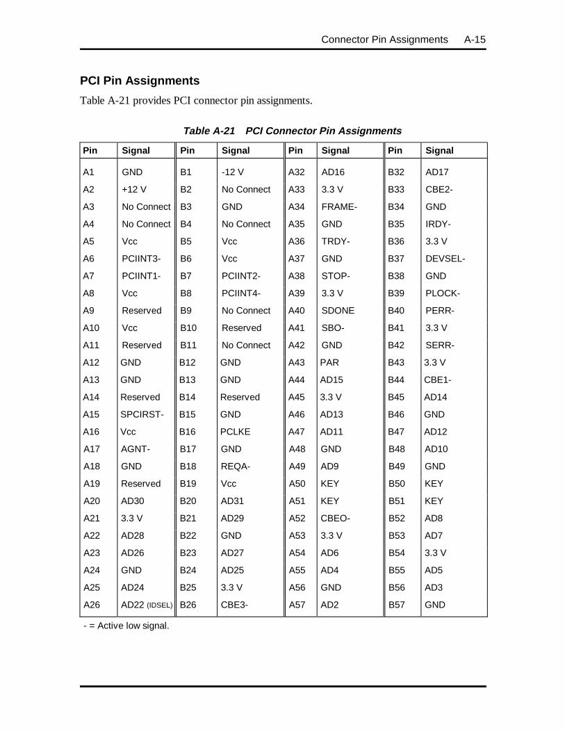
Connector Pin Assignments A-15
PCI Pin Assignments
Table A-21 provides PCI connector pin assignments.
Table A-21 PCI Connector Pin Assignments
Pin Signal Pin Signal Pin Signal Pin Signal
A1 GND B1 -12 V A32 AD16 B32 AD17
A2 +12 V B2 No Connect A33 3.3 V B33 CBE2-
A3 No Connect B3 GND A34 FRAME- B34 GND
A4 No Connect B4 No Connect A35 GND B35 IRDY-
A5 Vcc B5 Vcc A36 TRDY- B36 3.3 V
A6 PCIINT3- B6 Vcc A37 GND B37 DEVSEL-
A7 PCIINT1- B7 PCIINT2- A38 STOP- B38 GND
A8 Vcc B8 PCIINT4- A39 3.3 V B39 PLOCK-
A9 Reserved B9 No Connect A40 SDONE B40 PERR-
A10 Vcc B10 Reserved A41 SBO- B41 3.3 V
A11 Reserved B11 No Connect A42 GND B42 SERR-
A12 GND B12 GND A43 PAR B43 3.3 V
A13 GND B13 GND A44 AD15 B44 CBE1-
A14 Reserved B14 Reserved A45 3.3 V B45 AD14
A15 SPCIRST- B15 GND A46 AD13 B46 GND
A16 Vcc B16 PCLKE A47 AD11 B47 AD12
A17 AGNT- B17 GND A48 GND B48 AD10
A18 GND B18 REQA- A49 AD9 B49 GND
A19 Reserved B19 Vcc A50 KEY B50 KEY
A20 AD30 B20 AD31 A51 KEY B51 KEY
A21 3.3 V B21 AD29 A52 CBEO- B52 AD8
A22 AD28 B22 GND A53 3.3 V B53 AD7
A23 AD26 B23 AD27 A54 AD6 B54 3.3 V
A24 GND B24 AD25 A55 AD4 B55 AD5
A25 AD24 B25 3.3 V A56 GND B56 AD3
A26 AD22 (IDSEL) B26 CBE3- A57 AD2 B57 GND
- = Active low signal.
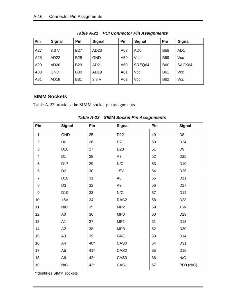
A-16 Connector Pin Assignments
Table A-21 PCI Connector Pin Assignments
Pin Signal Pin Signal Pin Signal Pin Signal
A27 3.3 V B27 AD23 A58 AD0 B58 AD1
A28 AD22 B28 GND A59 Vcc B59 Vcc
A29 AD20 B29 AD21 A60 SREQ64- B60 SACK64-
A30 GND B30 AD19 A61 Vcc B61 Vcc
A31 AD18 B31 3.3 V A62 Vcc B62 Vcc
SIMM Sockets
Table A-22 provides the SIMM socket pin assignments.
Table A-22 SIMM Socket Pin Assignments
Pin Signal Pin Signal Pin Signal
1 GND 25 D22 49 D8
2 D0 26 D7 50 D24
3 D16 27 D23 51 D9
4 D1 28 A7 52 D25
5 D17 29 N/C 53 D10
6 D2 30 +5V 54 D26
7 D18 31 A8 55 D11
8 D3 32 A9 56 D27
9 D19 33 N/C 57 D12
10 +5V 34 RAS2 58 D28
11 N/C 35 MP2 59 +5V
12 A0 36 MP0 60 D29
13 A1 37 MP1 61 D13
14 A2 38 MP3 62 D30
15 A3 39 GND 63 D14
16 A4 40* CAS0 64 D31
17 A5 41* CAS2 65 D15
18 A6 42* CAS3 66 N/C
19 N/C 43* CAS1 67 PD0 (N/C)
*Identifies SIMM sockets
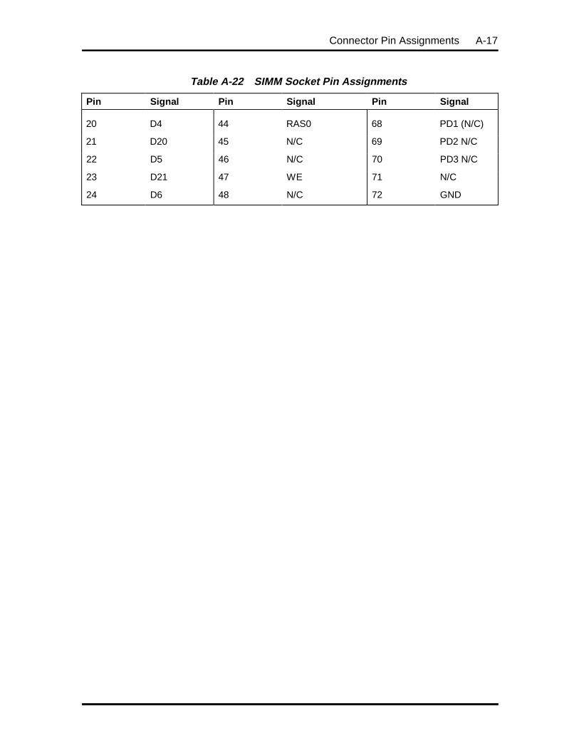
Connector Pin Assignments A-17
Table A-22 SIMM Socket Pin Assignments
Pin Signal Pin Signal Pin Signal
20 D4 44 RAS0 68 PD1 (N/C)
21 D20 45 N/C 69 PD2 N/C
22 D5 46 N/C 70 PD3 N/C
23 D21 47 WE 71 N/C
24 D6 48 N/C 72 GND
Appendix B
System Board Settings
This appendix provides jumper setting information for configuring a system that has specificrequirements.
Situations that require changing the jumper settings include the following:
� changing the processor speed setting
� recovering the BIOS
� denying access to CMOS Setup
� resetting the password
� clearing the system board CMOS values and restoring the default settings.
NOTE: The clear CMOS jumper is intended tobe used only if the BIOS has been corruptedduring a BIOS upgrade. A description of how touse the jumper is found later in this section under“BIOS Recovery.”
The system board in the computer contains a 24-pin block of configuration jumpers in a2 x 12 array.
CAUTION: Jumpers are set correctly at the factoryfor the configuration.
If the system requires a jumper change, changeonly the setting for that condition. Otherwise,keep the settings at their factory settings.

B-2 System Board Settings
CHANGING JUMPER SETTINGS
To change the jumper settings, follow these steps.
1. Power off and unplug the system and any peripheral devices.
WARNING: The system power must be offbefore changing switch settings.
2. Remove the system unit cover (see “Removing the System Unit Cover” inSection 3).
3. Locate the jumper bank on the system board (see Figure B-1).
You may have to remove any installed expansion boards to access the jumpers(see “Expansion Board Removal” in Section 3).
4. Change the jumper setting by lifting the plastic block and placing it on theappropriate pins as shown in the following figures. NECCSD recommends usingneedle-nose pliers to move a jumper.
5. Reinstall any removed expansion boards (see “Expansion Board Installation” inSection 3).
6. Replace the system unit cover (see “Replacing the System Unit Cover” inSection 3).
7. Plug in the power cord and turn on the computer.
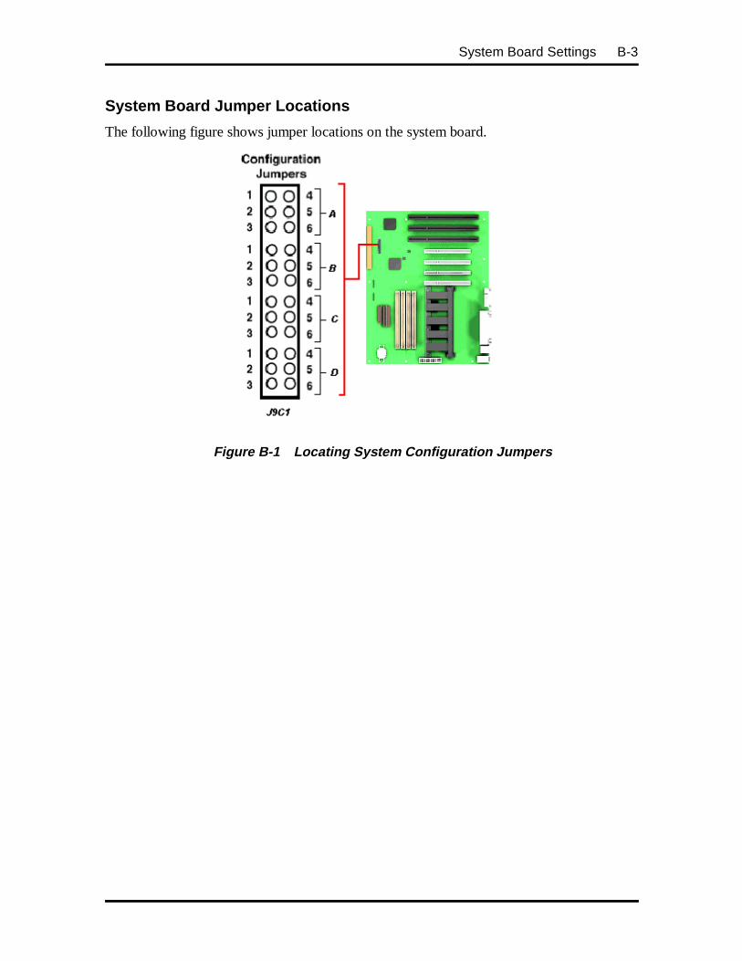
System Board Settings B-3
System Board Jumper Locations
The following figure shows jumper locations on the system board.
Figure B-1 Locating System Configuration Jumpers
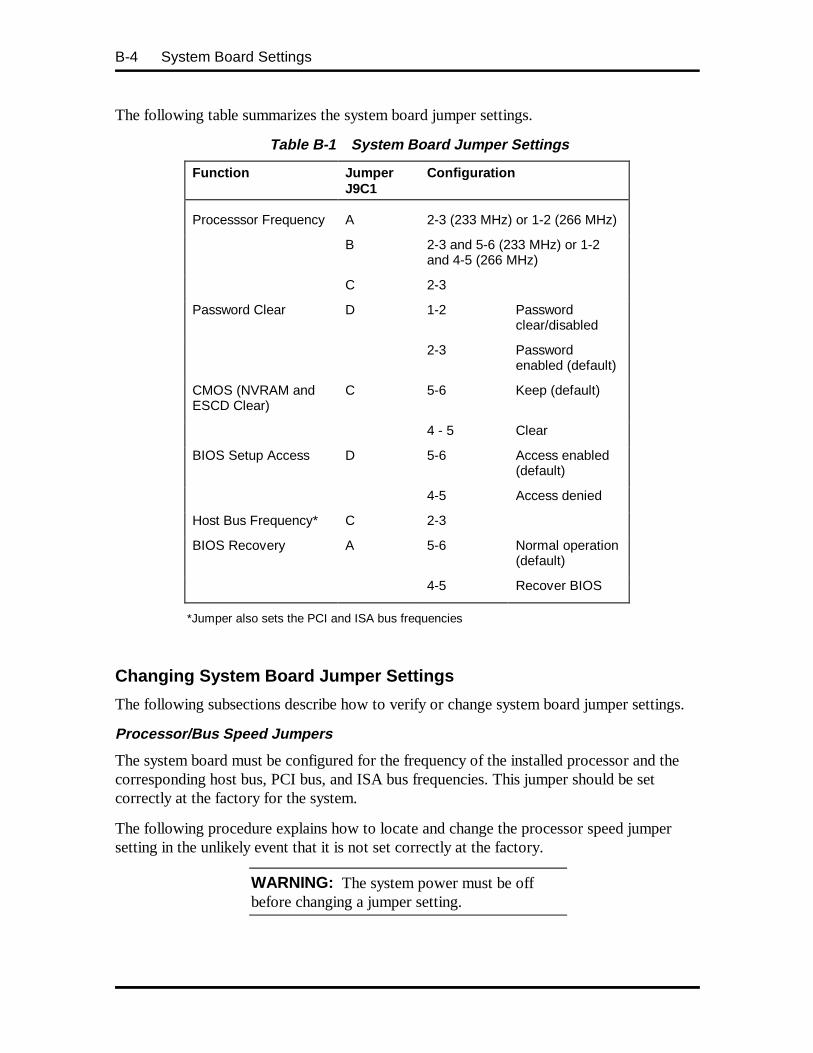
B-4 System Board Settings
The following table summarizes the system board jumper settings.
Table B-1 System Board Jumper Settings
Function JumperJ9C1
Configuration
Processsor Frequency A 2-3 (233 MHz) or 1-2 (266 MHz)
B 2-3 and 5-6 (233 MHz) or 1-2and 4-5 (266 MHz)
C 2-3
Password Clear D 1-2 Passwordclear/disabled
2-3 Passwordenabled (default)
CMOS (NVRAM andESCD Clear)
C 5-6 Keep (default)
4 - 5 Clear
BIOS Setup Access D 5-6 Access enabled(default)
4-5 Access denied
Host Bus Frequency* C 2-3
BIOS Recovery A 5-6 Normal operation(default)
4-5 Recover BIOS
*Jumper also sets the PCI and ISA bus frequencies
Changing System Board Jumper Settings
The following subsections describe how to verify or change system board jumper settings.
Processor/Bus Speed Jumpers
The system board must be configured for the frequency of the installed processor and thecorresponding host bus, PCI bus, and ISA bus frequencies. This jumper should be setcorrectly at the factory for the system.
The following procedure explains how to locate and change the processor speed jumpersetting in the unlikely event that it is not set correctly at the factory.
WARNING: The system power must be offbefore changing a jumper setting.
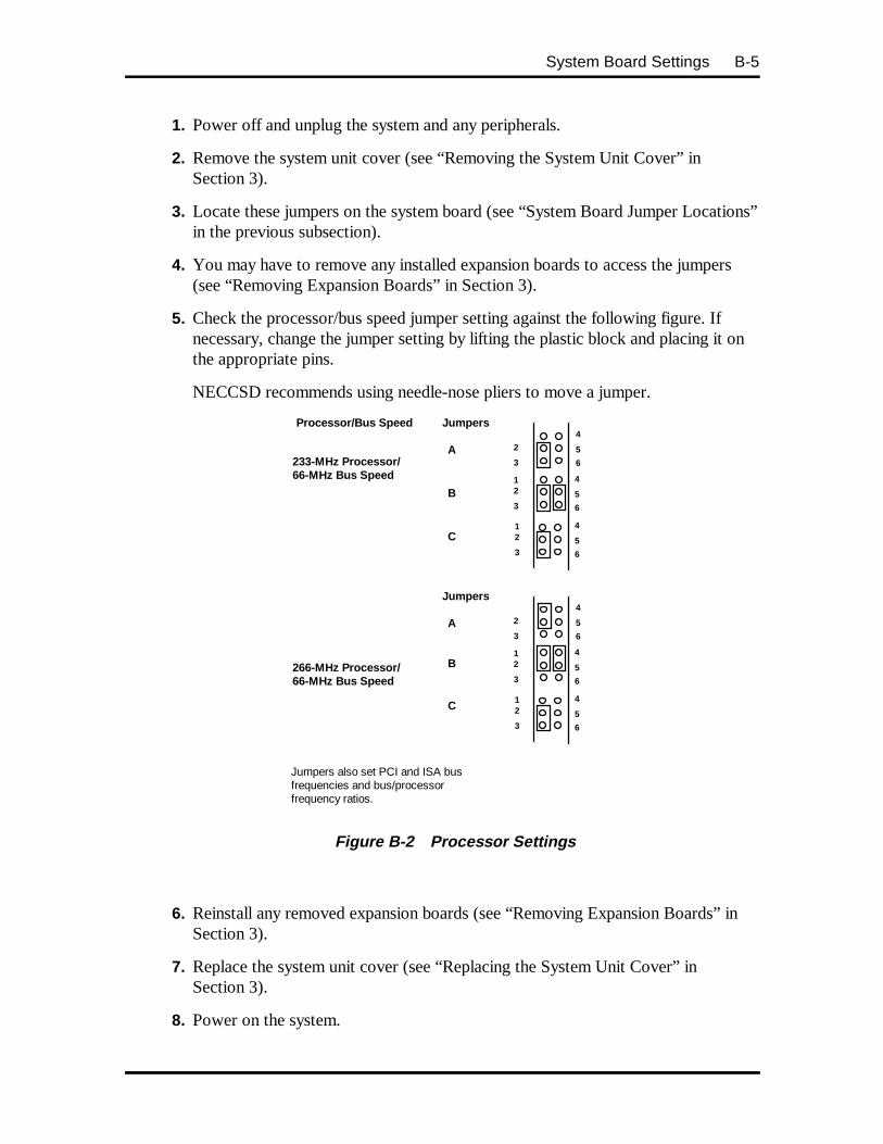
System Board Settings B-5
1. Power off and unplug the system and any peripherals.
2. Remove the system unit cover (see “Removing the System Unit Cover” inSection 3).
3. Locate these jumpers on the system board (see “System Board Jumper Locations”in the previous subsection).
4. You may have to remove any installed expansion boards to access the jumpers(see “Removing Expansion Boards” in Section 3).
5. Check the processor/bus speed jumper setting against the following figure. Ifnecessary, change the jumper setting by lifting the plastic block and placing it onthe appropriate pins.
NECCSD recommends using needle-nose pliers to move a jumper.
Figure B-2 Processor Settings
6. Reinstall any removed expansion boards (see “Removing Expansion Boards” inSection 3).
7. Replace the system unit cover (see “Replacing the System Unit Cover” inSection 3).
8. Power on the system.
Processor/Bus Speed
233-MHz Processor/66-MHz Bus Speed
Jumpers also set PCI and ISA busfrequencies and bus/processorfrequency ratios.
2
3
4
5
6
Jumpers
12
3
4
5
6
12
3
4
5
6
C
B
A
266-MHz Processor/66-MHz Bus Speed
Jumpers
A
B
C
2
3
12
3
12
3
4
5
6
4
5
6
4
5
6
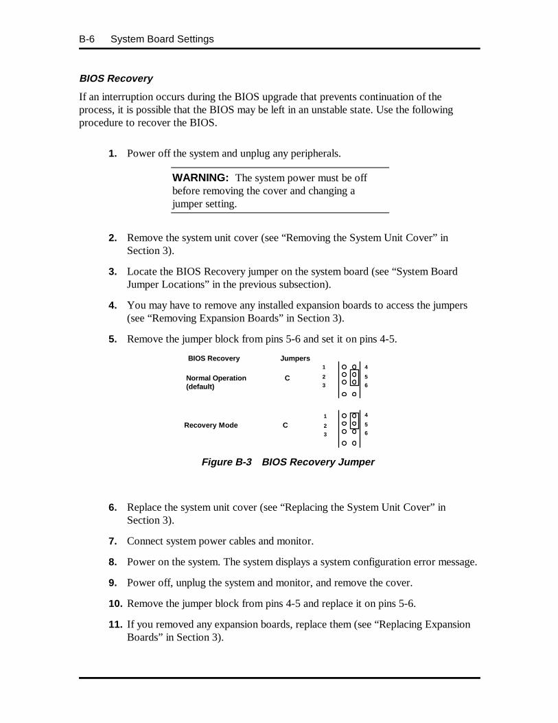
B-6 System Board Settings
BIOS Recovery
If an interruption occurs during the BIOS upgrade that prevents continuation of theprocess, it is possible that the BIOS may be left in an unstable state. Use the followingprocedure to recover the BIOS.
1. Power off the system and unplug any peripherals.
WARNING: The system power must be offbefore removing the cover and changing ajumper setting.
2. Remove the system unit cover (see “Removing the System Unit Cover” inSection 3).
3. Locate the BIOS Recovery jumper on the system board (see “System BoardJumper Locations” in the previous subsection).
4. You may have to remove any installed expansion boards to access the jumpers(see “Removing Expansion Boards” in Section 3).
5. Remove the jumper block from pins 5-6 and set it on pins 4-5.
BIOS Recovery
Normal Operation C(default)
Recovery Mode C
1
2
3
4
5
6
Jumpers
1
2
3
4
5
6
Figure B-3 BIOS Recovery Jumper
6. Replace the system unit cover (see “Replacing the System Unit Cover” inSection 3).
7. Connect system power cables and monitor.
8. Power on the system. The system displays a system configuration error message.
9. Power off, unplug the system and monitor, and remove the cover.
10. Remove the jumper block from pins 4-5 and replace it on pins 5-6.
11. If you removed any expansion boards, replace them (see “Replacing ExpansionBoards” in Section 3).

System Board Settings B-7
12. Replace the system unit cover. Reconnect the system power cables andperipheral devices.
13. Power on the system.
14. Run Setup (see Section 2).
Clearing CMOS
If you want to return the system to the factory default settings, use the following procedureto clear CMOS to the default factory settings.
CAUTION: Clearing CMOS changes the setupconfiguration, including hard disk settings.
1. Power off the system and unplug any peripherals.
WARNING: The system power must be offbefore removing the cover and changing ajumper setting.
2. Remove the system unit cover (see “Removing the System Unit Cover inSection 3).
3. Locate the CMOS Clear jumper on the system board (see “System Board JumperLocations” in the previous subsection). The default setting for this jumper is pins5-6 (keep CMOS settings).
You may have to remove any installed expansion boards to access the jumpers(see “Removing Expansion Boards” in Section 3).
4. Remove the jumper block from pins 4-5 and set it on pins 5-6.
Figure B-4 Clear CMOS Jumper
Clear CMOS
Normal Operation C(Default)
Clear CMOS C
1
2
3
4
5
6
Jumpers
1
2
3
14
4
5
6

B-8 System Board Settings
5. Replace the system unit cover (see “Replacing the System Unit Cover inSection 3).
6. Connect system power cables and monitor.
7. Power on the system. The system displays a system configuration error message.
8. Power off, unplug the system and monitor, and remove the cover.
9. Remove the jumper block from pins 5-6 and replace it on pins 4-5.
10. If you removed any expansion boards, replace them (see “Replacing ExpansionBoards” in Section 3).
11. Replace the system unit cover. Reconnect the system power cables andperipheral devices.
12. Power on the system.
13. Run Setup (see Chapter 2).
Denying Access to CMOS Setup
In special cases, you may want to deny the user access to CMOS setup. In this case youmust change the jumper from its default position. Use the following procedure to changethe jumper setting.
1. Power off the system and unplug any peripherals.
WARNING: The system power must be offbefore removing the cover and changing ajumper setting.
2. Remove the system unit cover (see “Removing the System Unit Cover” inSection 3).
3. Locate the CMOS Setup Access jumper on the system board (see “SystemBoard Jumper Locations” in the previous subsection).
4. You may have to remove any installed expansion boards to access the jumpers(see “Removing Expansion Boards” in Section 3).
5. Remove the jumper block from pins 5-6 and set it on pins 4-5.

System Board Settings B-9
CMOS Access
Access Allowed D(default)
Access Denied D
Jumpers
1
2
3
4
5
6
1
2
3
4
5
6
Figure B-5 CMOS Setup Access Jumper
6. Replace the system unit cover (see “Replacing the System Unit Cover” inSection 3).
7. Connect system power cables and monitor.
8. Power on the system. The system displays a system configuration error message.
9. Power off, unplug the system and monitor, and remove the cover.
10. Remove the jumper block from pins 4-5 and replace it on pins 5-6.
11. If you removed any expansion boards, replace them (see “Replacing ExpansionBoards” in Section 3).
12. Replace the system unit cover. Reconnect the system power cables andperipheral devices.
13. Power on the system.
14. Run Setup (see Section 2).
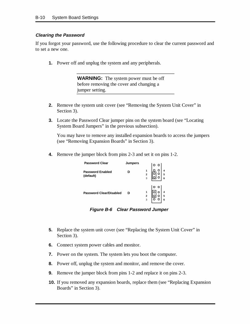
B-10 System Board Settings
Clearing the Password
If you forgot your password, use the following procedure to clear the current password andto set a new one.
1. Power off and unplug the system and any peripherals.
WARNING: The system power must be offbefore removing the cover and changing ajumper setting.
2. Remove the system unit cover (see “Removing the System Unit Cover” inSection 3).
3. Locate the Password Clear jumper pins on the system board (see “LocatingSystem Board Jumpers” in the previous subsection).
You may have to remove any installed expansion boards to access the jumpers(see “Removing Expansion Boards” in Section 3).
4. Remove the jumper block from pins 2-3 and set it on pins 1-2.
Password Clear
Password Enabled D(default)
Password Clear/Disabled D
Jumpers
1
2
3
4
5
6
1
2
3
4
5
6
Figure B-6 Clear Password Jumper
5. Replace the system unit cover (see “Replacing the System Unit Cover” inSection 3).
6. Connect system power cables and monitor.
7. Power on the system. The system lets you boot the computer.
8. Power off, unplug the system and monitor, and remove the cover.
9. Remove the jumper block from pins 1-2 and replace it on pins 2-3.
10. If you removed any expansion boards, replace them (see “Replacing ExpansionBoards” in Section 3).

System Board Settings B-11
11. Replace the system unit cover.
12. Power on the system.
13. Run Setup to set a new password (see Section 2).
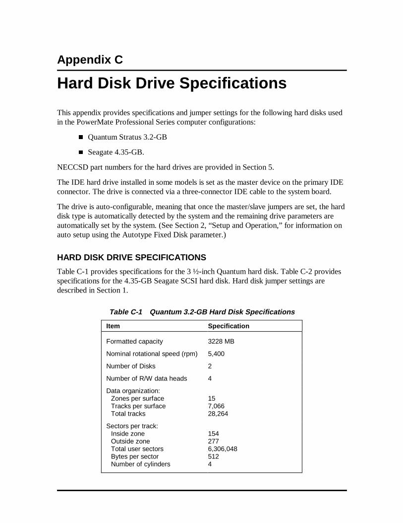
Appendix C
Hard Disk Drive Specifications
This appendix provides specifications and jumper settings for the following hard disks usedin the PowerMate Professional Series computer configurations:
� Quantum Stratus 3.2-GB
� Seagate 4.35-GB.
NECCSD part numbers for the hard drives are provided in Section 5.
The IDE hard drive installed in some models is set as the master device on the primary IDEconnector. The drive is connected via a three-connector IDE cable to the system board.
The drive is auto-configurable, meaning that once the master/slave jumpers are set, the harddisk type is automatically detected by the system and the remaining drive parameters areautomatically set by the system. (See Section 2, “Setup and Operation,” for information onauto setup using the Autotype Fixed Disk parameter.)
HARD DISK DRIVE SPECIFICATIONS
Table C-1 provides specifications for the 3 ½-inch Quantum hard disk. Table C-2 providesspecifications for the 4.35-GB Seagate SCSI hard disk. Hard disk jumper settings aredescribed in Section 1.
Table C-1 Quantum 3.2-GB Hard Disk Specifications
Item Specification
Formatted capacity 3228 MB
Nominal rotational speed (rpm) 5,400
Number of Disks 2
Number of R/W data heads 4
Data organization:Zones per surfaceTracks per surfaceTotal tracks
157,06628,264
Sectors per track:Inside zoneOutside zoneTotal user sectorsBytes per sectorNumber of cylinders
1542776,306,0485124
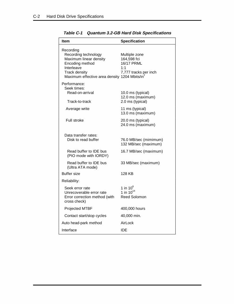
C-2 Hard Disk Drive Specifications
Table C-1 Quantum 3.2-GB Hard Disk Specifications
Item Specification
RecordingRecording technologyMaximum linear densityEncoding methodInterleaveTrack densityMaximum effective area density
Multiple zone164,598 fci16/17 PRML1:17,777 tracks per inch1204 Mbits/in2
Performance:Seek times:
Read-on-arrival
Track-to-track
10.0 ms (typical)12.0 ms (maximum)2.0 ms (typical)
Average write 11 ms (typical)13.0 ms (maximum)
Full stroke 20.0 ms (typical)24.0 ms (maximum)
Data transfer rates:Disk to read buffer
76.0 MB/sec (mimimum)132 MB/sec (maximum)
Read buffer to IDE bus(PIO mode with IORDY)
16.7 MB/sec (maximum)
Read buffer to IDE bus(Ultra ATA mode)
33 MB/sec (maximum)
Buffer size 128 KB
Reliability:
Seek error rateUnrecoverable error rateError correction method (withcross check)
1 in 106
1 in 1014
Reed Solomon
Projected MTBF 400,000 hours
Contact start/stop cycles 40,000 min.
Auto head-park method AirLock
Interface IDE
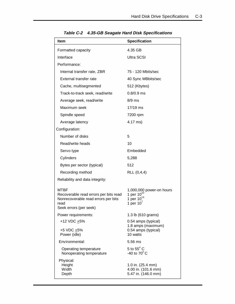
Hard Disk Drive Specifications C-3
Table C-2 4.35-GB Seagate Hard Disk Specifications
Item Specification
Formatted capacity 4.35 GB
Interface Ultra SCSI
Performance:
Internal transfer rate, ZBR 75 - 120 Mbits/sec
External transfer rate 40 Sync MBbits/sec
Cache, multisegmented 512 (Kbytes)
Track-to-track seek, read/write 0.8/0.9 ms
Average seek, read/write 8/9 ms
Maximum seek 17/19 ms
Spindle speed 7200 rpm
Average latency 4.17 ms)
Configuration:
Number of disks 5
Read/write heads 10
Servo type Embedded
Cylinders 5,288
Bytes per sector (typical) 512
Recording method RLL (0,4,4)
Reliability and data integrity:
MTBFRecoverable read errors per bits readNonrecoverable read errors per bitsreadSeek errors (per seek)
1,000,000 power-on hours1 per 1010
1 per 1014
1 per 107
Power requirements: 1.3 lb (610 grams)
+12 VDC +5%
+5 VDC +5%Power (idle)
0.54 amps (typical)1.8 amps (maximum)0.54 amps (typical)10 watts
Environmental: 5.56 ms
Operating temperatureNonoperating temperature
5 to 55o C-40 to 70o C
Physical:HeightWidthDepth
1.0 in. (25.4 mm)4.00 in. (101.6 mm)5.47 in. (146.0 mm)

C-4 Hard Disk Drive Specifications
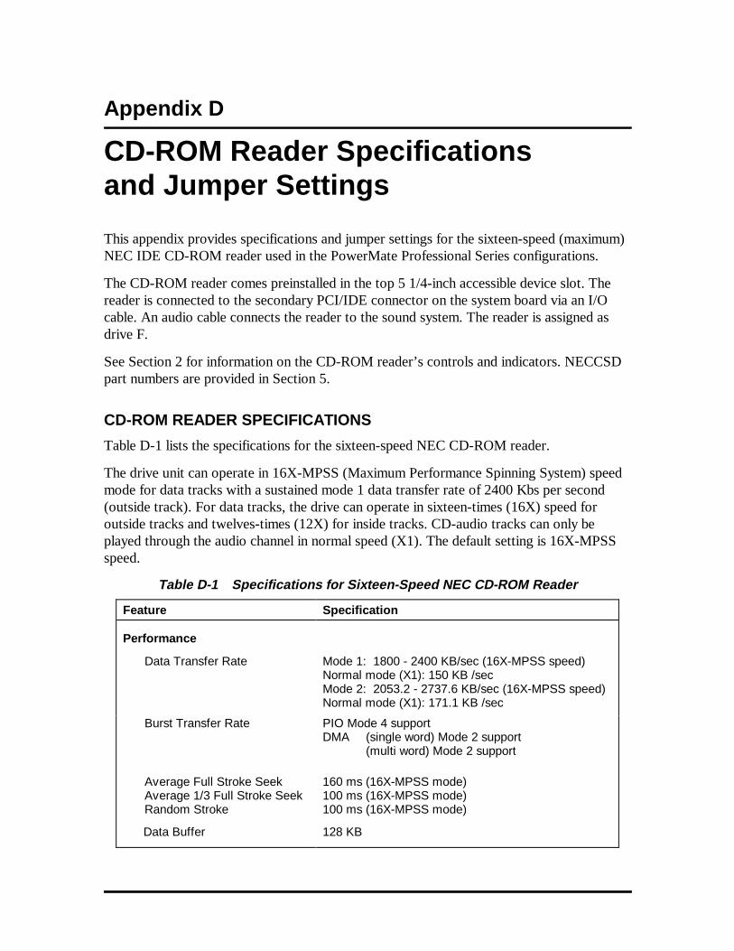
Appendix D
CD-ROM Reader Specificationsand Jumper Settings
This appendix provides specifications and jumper settings for the sixteen-speed (maximum)NEC IDE CD-ROM reader used in the PowerMate Professional Series configurations.
The CD-ROM reader comes preinstalled in the top 5 1/4-inch accessible device slot. Thereader is connected to the secondary PCI/IDE connector on the system board via an I/Ocable. An audio cable connects the reader to the sound system. The reader is assigned asdrive F.
See Section 2 for information on the CD-ROM reader’s controls and indicators. NECCSDpart numbers are provided in Section 5.
CD-ROM READER SPECIFICATIONS
Table D-1 lists the specifications for the sixteen-speed NEC CD-ROM reader.
The drive unit can operate in 16X-MPSS (Maximum Performance Spinning System) speedmode for data tracks with a sustained mode 1 data transfer rate of 2400 Kbs per second(outside track). For data tracks, the drive can operate in sixteen-times (16X) speed foroutside tracks and twelves-times (12X) for inside tracks. CD-audio tracks can only beplayed through the audio channel in normal speed (X1). The default setting is 16X-MPSSspeed.
Table D-1 Specifications for Sixteen-Speed NEC CD-ROM Reader
Feature Specification
Performance
Data Transfer Rate Mode 1: 1800 - 2400 KB/sec (16X-MPSS speed)Normal mode (X1): 150 KB /secMode 2: 2053.2 - 2737.6 KB/sec (16X-MPSS speed)Normal mode (X1): 171.1 KB /sec
Burst Transfer Rate PIO Mode 4 supportDMA (single word) Mode 2 support
(multi word) Mode 2 support
Average Full Stroke SeekAverage 1/3 Full Stroke SeekRandom Stroke
160 ms (16X-MPSS mode)100 ms (16X-MPSS mode)100 ms (16X-MPSS mode)
Data Buffer 128 KB
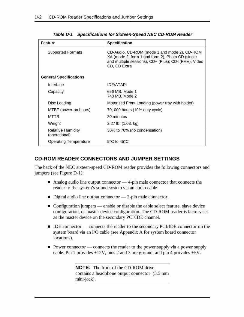
CD-ROM Reader Specifications and Jumper SettingsD-2
Table D-1 Specifications for Sixteen-Speed NEC CD-ROM Reader
Feature Specification
Supported Formats CD-Audio, CD-ROM (mode 1 and mode 2), CD-ROMXA (mode 2, form 1 and form 2), Photo CD (singleand multiple sessions), CD+ (Plus); CD-I(FMV), VideoCD, CD Extra
General Specificat ions
Interface IDE/ATAPI
Capacity 656 MB, Mode 1748 MB, Mode 2
Disc Loading Motorized Front Loading (power tray with holder)
MTBF (power-on hours) 70, 000 hours (10% duty cycle)
MTTR 30 minutes
Weight 2.27 lb. (1.03. kg)
Relative Humidity(operational)
30% to 70% (no condensation)
Operating Temperature 5°C to 45°C
CD-ROM READER CONNECTORS AND JUMPER SETTINGS
The back of the NEC sixteen-speed CD-ROM reader provides the following connectors andjumpers (see Figure D-1):
� Analog audio line output connector — 4-pin male connector that connects thereader to the system’s sound system via an audio cable.
� Digital audio line output connector — 2-pin male connector.
� Configuration jumpers — enable or disable the cable select feature, slave deviceconfiguration, or master device configuration. The CD-ROM reader is factory setas the master device on the secondary PCI/IDE channel.
� IDE connector — connects the reader to the secondary PCI/IDE connector on thesystem board via an I/O cable (see Appendix A for system board connectorlocations).
� Power connector — connects the reader to the power supply via a power supplycable. Pin 1 provides +12V, pins 2 and 3 are ground, and pin 4 provides +5V.
NOTE: The front of the CD-ROM drivecontains a headphone output connector (3.5 mmmini-jack).
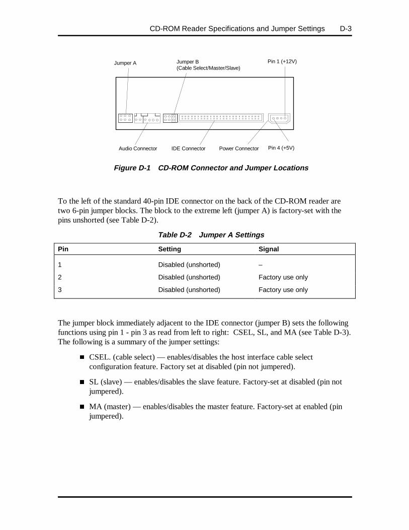
CD-ROM Reader Specifications and Jumper Settings D-3
Figure D-1 CD-ROM Connector and Jumper Locations
To the left of the standard 40-pin IDE connector on the back of the CD-ROM reader aretwo 6-pin jumper blocks. The block to the extreme left (jumper A) is factory-set with thepins unshorted (see Table D-2).
Table D-2 Jumper A Settings
Pin Setting Signal
1 Disabled (unshorted) –
2 Disabled (unshorted) Factory use only
3 Disabled (unshorted) Factory use only
The jumper block immediately adjacent to the IDE connector (jumper B) sets the followingfunctions using pin 1 - pin 3 as read from left to right: CSEL, SL, and MA (see Table D-3).The following is a summary of the jumper settings:
� CSEL. (cable select) — enables/disables the host interface cable selectconfiguration feature. Factory set at disabled (pin not jumpered).
� SL (slave) — enables/disables the slave feature. Factory-set at disabled (pin notjumpered).
� MA (master) — enables/disables the master feature. Factory-set at enabled (pinjumpered).
IDE Connector Power Connector
Jumper B(Cable Select/Master/Slave)
Audio Connector
Jumper A Pin 1 (+12V)
Pin 4 (+5V)

CD-ROM Reader Specifications and Jumper SettingsD-4
Table D-3 Jumper B Settings
Pin Setting Signal
1 Disabled (unshorted) CSEL (cable select)
2 Disabled (unshorted) SL (slave)
3 Enabled (shorted) Master (default setting)
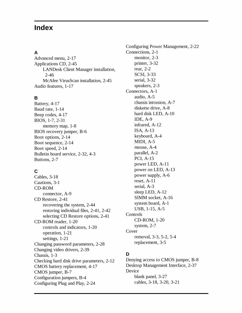
Index
AAdvanced menu, 2-17Applications CD, 2-45
LANDesk Client Manager installation,2-46
McAfee VirusScan installation, 2-45Audio features, 1-17
BBattery, 4-17Baud rate, 1-14Beep codes, 4-17BIOS, 1-7, 2-31
memory map, 1-8BIOS recovery jumper, B-6Boot options, 2-14Boot sequence, 2-14Boot speed, 2-14Bulletin board service, 2-32, 4-3Buttons, 2-7
CCables, 3-18Cautions, 3-1CD-ROM
connector, A-9CD Restore, 2-41
recovering the system, 2-44restoring individual files, 2-41, 2-42selecting CD Restore options, 2-41
CD-ROM reader, 1-20controls and indicators, 1-20operation, 1-21settings, 1-21
Changing password parameters, 2-28Changing video drivers, 2-39Chassis, 1-3Checking hard disk drive parameters, 2-12CMOS battery replacement, 4-17CMOS jumper, B-7Configuration jumpers, B-4Configuring Plug and Play, 2-24
Configuring Power Management, 2-22Connections, 2-1
monitor, 2-3printer, 3-32rear, 2-2SCSI, 3-33serial, 3-32speakers, 2-3
Connectors, A-1audio, A-5chassis intrusion, A-7diskette drive, A-8hard disk LED, A-10IDE, A-9infrared, A-12ISA, A-13keyboard, A-4MIDI, A-5mouse, A-4parallel, A-2PCI, A-15power LED, A-11power on LED, A-13power supply, A-6reset, A-11serial, A-3sleep LED, A-12SIMM socket, A-16system board, A-1USB, 1-15, A-5
ControlsCD-ROM, 1-20system, 2-7
Coverremoval, 3-3, 5-2, 5-4replacement, 3-5
DDenying access to CMOS jumper, B-8Desktop Management Interface, 2-37Device
blank panel, 3-27cables, 3-18, 3-20, 3-21
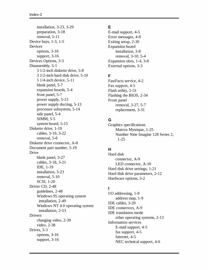
Index-2
installation, 3-23, 3-29preparation, 3-18removal, 5-11
Device bays, 1-3, 1-5Devices
options, 3-16support, 3-16
Devices Options, 3-3Disassembly, 5-1
3 1/2-inch diskette drive, 5-83 1/2-inch hard disk drive, 5-105 1/4-inch device, 5-11blank panel, 5-7expansion boards, 5-4front panel, 5-7power supply, 5-13power supply ducting, 5-13processor subsystem, 5-14side panel, 5-4SIMM, 5-5system board, 5-15
Diskette drive, 1-19cables, 3-19, 3-22removal, 5-8
Diskette drive connector, A-8Document part number, 5-19Drive
blank panel, 3-27cables, 3-18, 3-21IDE, 1-19installation, 3-23removal, 5-10SCSI, 1-20
Driver CD, 2-48guidelines, 2-48Windows 95 operating systeminstallation, 2-49
Windows NT 4.0 operating systeminstallation, 2-53
Driverschanging video, 2-39video, 2-38
Drives, 3-3options, 3-16support, 3-16
EE-mail support, 4-5Error messages, 4-8Exiting setup, 2-30Expansion board
installation, 3-8removal, 3-10, 5-4
Expansion slots, 1-4, 3-8External options, 3-3
FFastFacts service, 4-2Fax support, 4-5Flash utility, 2-31Flashing the BIOS, 2-34Front panel
removal, 3-27, 5-7replacement, 3-31
GGraphics specifications
Matrox Mystique, 1-25Number Nine Imagine 128 Series 2,1-25
HHard disk
connector, A-9LED connector, A-10
Hard disk drive settings, 1-21Hard disk drive parameters, 2-12Hardware options, 3-2
II/O addressing, 1-9
address map, 1-9IDE cables, 3-20IDE connectors, A-9IDE translation mode
other operating systems, 2-13Information services
E-mail support, 4-5fax support, 4-5Internet, 4-5NEC technical support, 4-6
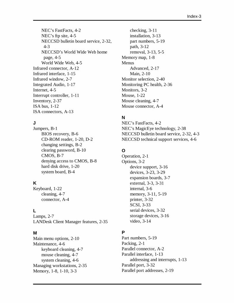
Index-3
NEC’s FastFacts, 4-2NEC’s ftp site, 4-5NECCSD bulletin board service, 2-32,4-3
NECCSD’s World Wide Web homepage, 4-5
World Wide Web, 4-5Infrared connector, A-12Infrared interface, 1-15Infrared window, 2-7Integrated Audio, 1-17Internet, 4-5Interrupt controller, 1-11Inventory, 2-37ISA bus, 1-12ISA connectors, A-13
JJumpers, B-1
BIOS recovery, B-6CD-ROM reader, 1-20, D-2changing settings, B-2clearing password, B-10CMOS, B-7denying access to CMOS, B-8hard disk drive, 1-20system board, B-4
KKeyboard, 1-22
cleaning, 4-7connector, A-4
LLamps, 2-7LANDesk Client Manager features, 2-35
MMain menu options, 2-10Maintenance, 4-6
keyboard cleaning, 4-7mouse cleaning, 4-7system cleaning, 4-6
Managing workstations, 2-35Memory, 1-8, 1-10, 3-3
checking, 3-11installation, 3-13part numbers, 5-19path, 3-12removal, 3-13, 5-5
Memory map, 1-8Menus
Advanced, 2-17Main, 2-10
Monitor selection, 2-40Monitoring PC health, 2-36Monitors, 3-2Mouse, 1-22Mouse cleaning, 4-7Mouse connector, A-4
NNEC’s FastFacts, 4-2NEC’s MagicEye technology, 2-38NECCSD bulletin board service, 2-32, 4-3NECCSD technical support services, 4-6
OOperation, 2-1Options, 3-2
device support, 3-16devices, 3-23, 3-29expansion boards, 3-7external, 3-3, 3-31internal, 3-6memory, 3-11, 5-19printer, 3-32SCSI, 3-33serial devices, 3-32storage devices, 3-16video, 3-14
PPart numbers, 5-19Packing, 2-1Parallel connector, A-2Parallel interface, 1-13
addressing and interrupts, 1-13Parallel port, 3-32Parallel port addresses, 2-19
Index-4
Passwordchanging entries, 2-28setting, 2-27
PC health indicator, 2-35PC Health meter, 2-36PCI connectors, A-15PCI local bus, 1-12PCI/IDE ports, 1-13Pentium II, 1-1, 1-7, 1-24Peripheral submenu, 2-18Pin Assignments, A-1Plug and Play, 1-12POST, 2-7Power cables, 3-21Power LED connector, A-11Power supply, 1-22
removal, 5-13Power supply connector, A-6Precautions, 3-1Printer installation, 3-32
installation, 3-32
RReassembly, 5-1Repair, 5-1
disassembly, 5-1reassembly, 5-1
Reset connector, A-11Restoring individual files, 2-42Restoring system software
restore individual files, 2-42–2-44restore indvidual files, 2-41system recovery, 2-41, 2-44–2-45
SSCSI, 1-18, 1-20
installation, 3-33SCSI board, 1-18Secondary cache, 1-7Serial COM port addresses, 2-19Serial connectors, A-3Serial device
installation, 3-32Serial interface, 1-14
specifications, 1-14Serial port, 3-32
Setting passwords, 2-27Setting system date/time, 2-11Setting user and administrative passwords,2-29
Setup, 2-1Setup and operation, 2-1
Applications CD, 2-45CD Restore, 2-40Driver CD, 2-50Flash utility, 2-31LANDesk Client Manager 2-35SCSISelect utility, 2-34Setup utility, 2-7starting up, 2-7system setup, 2-1unpacking, 2-1video drivers, 2-38
Setup utility, 2-7Setup utility uses, 2-8Side panel removal, 3-26, 5-4SIMM
installation, 3-13removal, 3-13, 5-5
SIMMs, 1-10Slot locations, 3-8Speakers, 1-22, 2-3Specifications, 1-23
CD-ROM reader, D-1hard disk, C-1
Starting Setup utility, 2-9Switches. See JumpersSystem BIOS, 1-7System board, 1-4
BIOS, 1-7chip sets, 1-5features, 1-4infrared interface, 1-15interrupt controller, 1-11ISA bus, 1-12jumper setting, B-1jumpers, B-4parallel interface, 1-13PCI local bus, 1-12PCI/IDE ports, 1-13processor, 1-7removal, 5-14
Index-5
secondary cache, 1-7System cleaning, 4-6System controls, 2-7System memory, 1-10System recovery, 2-41, 2-44, 2-45System restore options, 2-41System setup, 2-1System Unit Cover
removal, 3-3, 5-2replacement, 3-5
TTechnical support, 4-6Troubleshooting, 4-8
beep codes, 4-17error messages, 4-8problems and solutions, 4-11
Typematic rate delay, 2-16
UUniversal Serial Bus, 1-15Unpacking, 2-1Using DMI, 2-37Using the SCSISelect utility, 2-34Utilities
Flash, 2-33SCSISelect, 2-36Setup, 2-7
VVideo board, 1-15
playback, 1-17support interface, 1-16upgrade, 3-14
Voltage select switch, 2-1

(For United States Use Only)
FEDERAL COMMUNICATIONS COMMISSIONRADIO FREQUENCY INTERFERENCE STATEMENT
WARNING: Changes or modifications to this unit not expressly approved by the partyresponsible for compliance could void the user’s authority to operate the equipment.
NOTE: This equipment has been tested and found to comply with the limits for a Class Bdigital device, pursuant to Part 15 of the FCC Rules. These limits are designed to providereasonable protection against harmful interference in a residential installation. Thisequipment generates, uses and can radiate radio frequency energy and, if not installed andused in accordance with the instructions, may cause harmful interference to radiocommunications.
However, there is no guarantee that interference will not occur in a particular installation. Ifthis equipment does cause harmful interference to radio or television reception, which canbe determined by turning the equipment off and on, the user is encouraged to try to correctthe interference by one or more of the following measures.
� Reorient or relocate the receiving antenna.
� Increase the separation between the equipment and receiver.
� Connect the equipment to an outlet on a circuit different from the one to which thereceiver is connected.
Use shielded and properly grounded I/O and power cables to ensure compliance of this unitto the specified limits of the rules.
(For Canadian Use Only)This Class B digital apparatus meets all requirements of the Canadian Interference-CausingEquipment Regulations.
Cet appareil numérique de la classe B repecte toutes les exigences du Règlement sur lematériel brouilleur du Canada.

BATTERY REPLACEMENT
A lithium battery in your computer maintains system configuration information. In the eventthat the battery fails to maintain system configuration information, NEC recommends thatyou replace the battery. See Chapter 4 for battery replacement information.
WARNING: There is a danger of explosion if the battery is incorrectly replaced. Replaceonly with the same or equivalent type recommended by the manufacturer. Discard usedbatteries according to the manufacturer’s instructions.
ATTENTION: Il y a danger d’explosion s’il y a replacement incorrect de la batterie.Remplacer uniquement avec une batterie du même type ou d’un type recommandé par leconstructeur. Mettre au rébut les batteries usagées conformément aux instructions dufabricant.
BATTERY DISPOSAL
Do not place used batteries in your regular trash.
The nickel-cadmium or nickel metal-hydride batteries must be collected, recycled, ordisposed of in an environmentally-approved manner.
The incineration, landfilling, or mixing of batteries with the municipal solid waste stream isprohibited by law in most areas.
Return batteries to a federal or state approved battery recycler. This may be whereyou purchased the battery or a local seller of automotive batteries. In MINNESOTA, call1-800-225-PRBA if further disposal information is required.
Contact your local waste management officials for other information regarding theenvironmentally sound collection, recycling, and disposal of the batteries.