proposal - michigan state university · 1 proposal automated 3d model building using a robot and an...
TRANSCRIPT
1
PROPOSAL
Automated 3D Model Building Using a Robot and an RGB-Depth Camera
Michigan State University ECE 480 - Senior Design
Team 2 20 February 2015
Sponsor: Dr. Daniel Morris
Facilitator: Dr. Hayder Radha
Manager: David Zoltowski Webmaster: Nick Saxton Lab Coordinator: Nick Zuzow Document Prep: Kexiang Qian Presentation Prep: Jacob Kneibel
Executive Summary With the widening availability of RGB-Depth cameras to industry and to consumers, new applications for these sensors are in high demand. World modeling is one such application, and while done before in various research projects, the process of using RGB-Depth cameras to model a space has yet to become an automated process. The goal of this project is to combine a robotic moving platform and a commercially available RGB-Depth camera to autonomously build a 3D model of a room. The combined device will require additional structural supports and power. A successful device will be able to localize its position when capturing images and integrate images together to build a 3D model. The robot should be able to completely map a room without getting stuck or running out of power and should do so in a timely manner.
2
Table of Contents 1. Introduction……………………………………………………………………………………..3 2. Background…………………………………………………………………………………......3 3. Design Specifications…………………………………………………………………………..5 4. FAST Diagram…………………………………………………………………………............5 5. Conceptual Design Descriptions…………………………………………………………….....7 6. Ranking of Conceptual Designs……………………………………………………………......8 7. Proposed Solution………………………………………………………………………….......9 8. Risk Analysis……………………………………………………………………………….....12 9. Project Management Plan…………………………………………………………………......12 10. Budget……………………………………………………………………………………......14 11. References................................................................................................................................15
3
1 Introduction The goal of this project is to produce a combined piece of hardware (robot, camera, and onboard computer) capable of entering an unknown environment and autonomously building a 3D model of that environment. The process should be completed in a reasonable amount of time, which will be defined as less than thirty minutes. The robot must navigate the room without getting stuck to complete the goal. A basic requirement for the 3D model is that it must include objects up to and including the height of a table. Performance goals include a model that incorporates objects above table height, texture, and color. Two other needs are reliability and reproducibility. First, the robot should be able to build a complete 3D model a large majority of the time. Next, all of the hardware and software should be documented and delivered to the sponsor so that the project can be replicated and further developed. Several challenging aspects are involved in automating 3D modeling. First, there are several hardware related issues that must be addressed to make this a truly automated process. The RGB-Depth camera must be mounted on a moving platform (robot) that can be programmed to follow a certain path. Additionally, the camera requires power and a computer to relay information. Therefore, the robot must be able to support the weight of both the camera and the computer without losing its ability to move around an environment. The second challenge is the mapping and localization problem. When the RGB-Depth camera captures an image, it receives location measurements with associated RGB and depth values. Therefore, the camera does not know from what point in the environment it captured the image. To overcome this, the data from several different images of the environment must be combined to determine not only the robot’s path through the space but also the pose (angle relative to the path) it captured the image from. This can be a computationally intensive process leading to a new problem: the onboard computer lacks the computational power to perform the necessary calculations. This requires that the data the camera receives be sent to a better equipped off board system for processing, a process that must occur in real-time. Finally, all of the data from the RGB-Depth camera must be combined into a cohesive and complete 3D model of the environment. This involves stitching the many images together while accounting for both noise and bias. This is also a computationally taxing process and cannot be performed onboard. 2 Background 2.1 Overview With current technology, the traditional 2D floor plan does not satisfy people’s desires. In commercial activities, 2D panoramic photos and rotated continuous photos have been used to display 3D environments. The market for 3D models is large, and with 3D models, customers can be on the scene instead of viewing traditional pictures. For more importance uses, building a reliable 3D model in a short time automatically will contribute to exploring an unfamiliar environment and even can be used by 3D printing.
4
Before the advent of RGB-Depth cameras, 3D models of objects had to be constructed one of three ways: by hand in a 3D modeling software application, using a 3D scanner, or capturing several images of an object from various points of view with a traditional camera. The software method, while still used today to make movies and video games, can be very time consuming and often contain slight inaccuracies. Research into the use of 3D scanners began in the 1980s and scanners capable of producing high-fidelity 3D models exist today. However, these scanners are typically quite slow and there is a trade-off between the size of an object capable of being modeled and the cost of the scanner [1]. Several images captured with a traditional camera can be stitched together to create a quasi-3D model, but this method fails to create a true model of the object and in order to get a final result that is close to resembling the original object, time-consuming software must be used for the stitching process [2]. Now that RGB-Depth cameras are widely available to consumers and commercial enterprises alike, these previous methods of 3D modeling can be replaced by a faster, more accurate approach. While being able to model individual objects in an easier manner with these cameras is certainly appreciated, they possess a more compelling feature, the ability to create 3D models of entire environments quickly and relatively inexpensively. A fairly large amount of research has been done utilizing this capability, however most of it has been performed in a manual, hand-held way [3]. Automating this process would be very beneficial from several standpoints, from potential use in military operations to improved accessibility for physically handicapped people. 2.2 Mapping and Localization In the field of robotics, the real-time mapping of an environment and knowledge of location is referred to as Simultaneous Localization and Mapping (SLAM). There has been a large interest in the area of research and several methods have been created that can solve this problem. Different sensors need different algorithms to properly produce a map of the environment. These different algorithms can vary in complexity based off of the sensors, and the degree of accuracy required. One algorithm, FastSLAM [4], uses knowledge of the robot’s movement and path to create a relative location and then maps the area around the robot identifying landmarks individually. This method uses multiple sensors to partition the SLAM problem. The SLAM problem is important to the task of creating the 3D model. To bring a set of different RGB-D images together the relative position of the image needs to be known. In addition to using SLAM to stitch images together in a 3D model, the SLAM algorithm will be needed to correctly move the robot to obtain the images for the model. In a room the robot needs to be able to move unhindered, so a map needs to be created to inform the robot to avoid obstacles in the room. The robot also needs to be instructed to move towards areas that are incomplete on the map. 2.3 Data Transmission In previous 3D modeling projects, the data produced by the RGB-Depth camera was handled in one of two ways. Either the camera was directly connected to a computer capable of performing the complex and computationally intensive calculations on the data necessary for constructing the model, or the data was transmitted over a network to a separate machine for processing. A
5
2011 study conducted by the Imperial College of London and Microsoft Research produced 3D models of environments in real-time using the Microsoft Kinect. In this case, the Kinect was directly connected to a powerful enough computer to process the data the camera produced [5]. In 2012, a research team from the University of Bristol produced a handheld unit utilizing the Kinect that communicated the camera’s data wirelessly to a more powerful computer to display the model in real-time [3]. 2.4 Building a 3D Model A large part of this project will be processing the images from the depth camera, and converting the images into a 3D model. This will require a large amount of image manipulation including detecting edges, perspective transformation, image stitching, and image smoothing. Algorithms to reconstruct a 3D model from depth cameras have been developed and are freely available for use.
1. Real-time 3D Reconstruction at Scale using Voxel Hashing [6] a. This is a system created by Matthias NieBner and his team at Stanford University.
This system is used for large and fine scale volumetric reconstruction based on a simple spatial hashing scheme that compresses space, and allows for real-time access and updates of implicit surface data.
2. Kinect Fusion [5,7] a. This is used for 3D object scanning and model creation. It allows a user to capture
a scene with the Kinect camera while simultaneously seeing and interacting with a 3D model of that same scene. Kinect Fusion was developed specifically to be used with the Kinect camera for Windows, and it could be extremely useful when it comes to completing this part of the project.
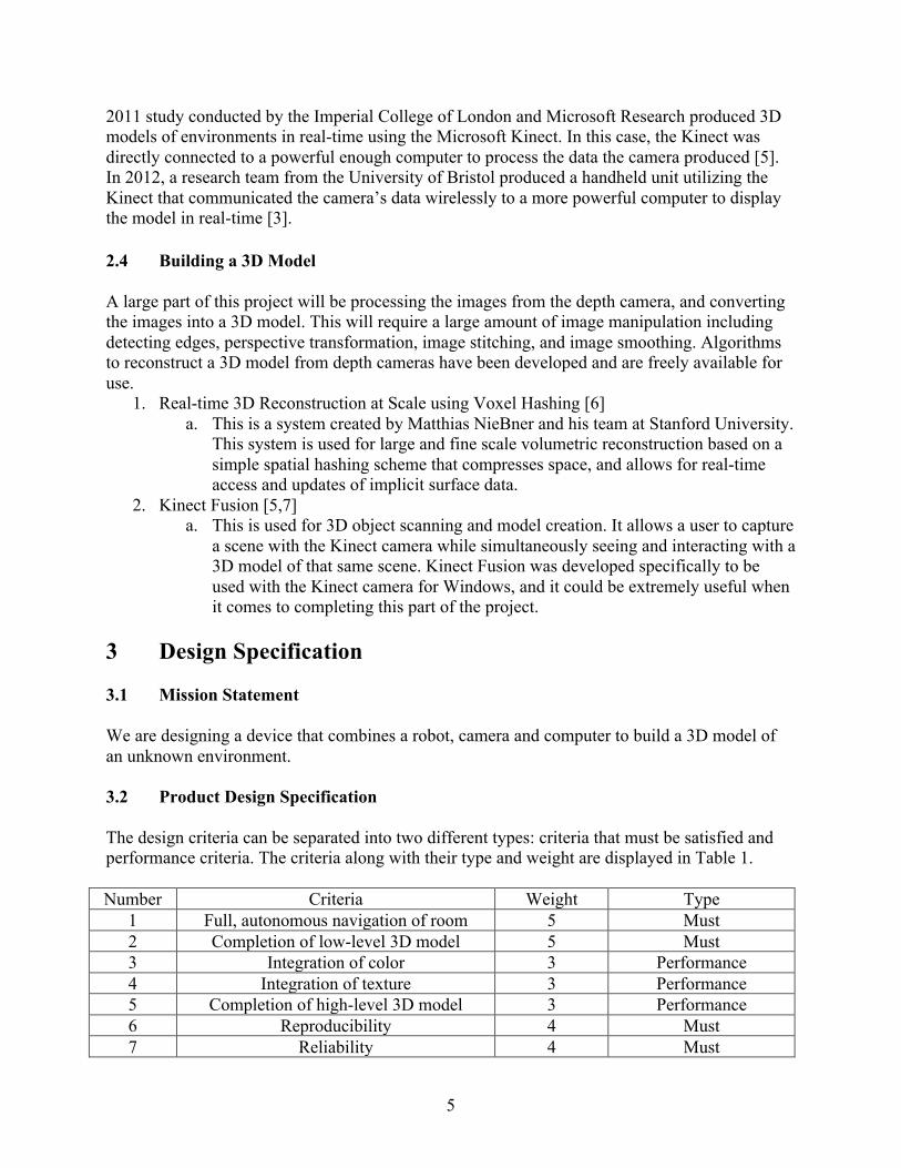
3 Design Specification 3.1 Mission Statement We are designing a device that combines a robot, camera and computer to build a 3D model of an unknown environment. 3.2 Product Design Specification The design criteria can be separated into two different types: criteria that must be satisfied and performance criteria. The criteria along with their type and weight are displayed in Table 1. Number Criteria Weight Type
1 Full, autonomous navigation of room 5 Must 2 Completion of low-level 3D model 5 Must 3 Integration of color 3 Performance 4 Integration of texture 3 Performance 5 Completion of high-level 3D model 3 Performance 6 Reproducibility 4 Must 7 Reliability 4 Must
6
8 Speed 2 Performance 9 Model Quality 4 Performance
Table 1. Design Criteria
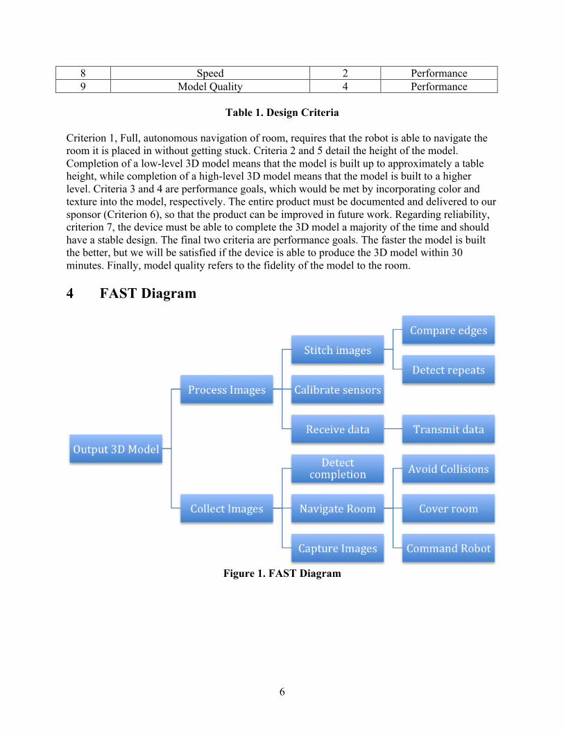
Criterion 1, Full, autonomous navigation of room, requires that the robot is able to navigate the room it is placed in without getting stuck. Criteria 2 and 5 detail the height of the model. Completion of a low-level 3D model means that the model is built up to approximately a table height, while completion of a high-level 3D model means that the model is built to a higher level. Criteria 3 and 4 are performance goals, which would be met by incorporating color and texture into the model, respectively. The entire product must be documented and delivered to our sponsor (Criterion 6), so that the product can be improved in future work. Regarding reliability, criterion 7, the device must be able to complete the 3D model a majority of the time and should have a stable design. The final two criteria are performance goals. The faster the model is built the better, but we will be satisfied if the device is able to produce the 3D model within 30 minutes. Finally, model quality refers to the fidelity of the model to the room. 4 FAST Diagram
Figure 1. FAST Diagram
7
5 Conceptual Design Descriptions 5.1 Design Descriptions Solution 1 For the first design, the iRobot Create 2 Programmable Robot will be combined with the Kinect v2 camera and laptop. The camera will be placed at about 1 meter above the iRobot using a steel structure. The Kinect v2 will be powered by an external power supply. Solution 2 The second design is similar to solution 1, but the camera is lowered to a height of about 1.5 feet. This while limiting the area that we can model above our robot, would lower the robot’s center of gravity and allow the robot to move into more places, e.g. under most tables. Solution 3 Another possible design solution involves the use of a Lego Mindstorm robot for navigating the room, acting as a platform for a Kinect v2 connected to a laptop for data collection and transmission. Solution 4 In the fourth design, a 1.5 ft. high steel holder structure will be built over the iRobot. The laptop will be placed over the top surface of the iRobot. There will be a bar to fix the Kinect camera at the end of the holder. Due to the unnecessary power supply to the sensor, it will be connected directly to the laptop. Solution 5 Compared with other solution, this design will use a rotatable arm, which can raise the camera up and down instead of using any holder structure with height. The arm will be placed over the iRobot and the laptop will be placed behind it. Solution 6 An additional design solution that was considered also involved the iRobot Create 2 platform and the Kinect v2 but traded the laptop for a smaller, lighter, single-board computer in the form of a Raspberry Pi. Solution 7 This design uses the iRobot and the Kinect v2, but the difference comes with the height and angle of the Kinect camera. In this solution both the Kinect and the laptop would be placed directly on the iRobot. The Kinect would be mounted at a set angle, approximately 30 degrees, using a small wedge shaped object. This allows for an adequate viewing height while minimizing the extra height of the physical equipment above the iRobot. Solution 8 The final possible solution is to use the iRobot Create2 Programmable Robot, the Kinect v2 camera, and laptop, but have the camera and robot connected to the laptop via a cord so that they can move while the laptop remains stationary.
8
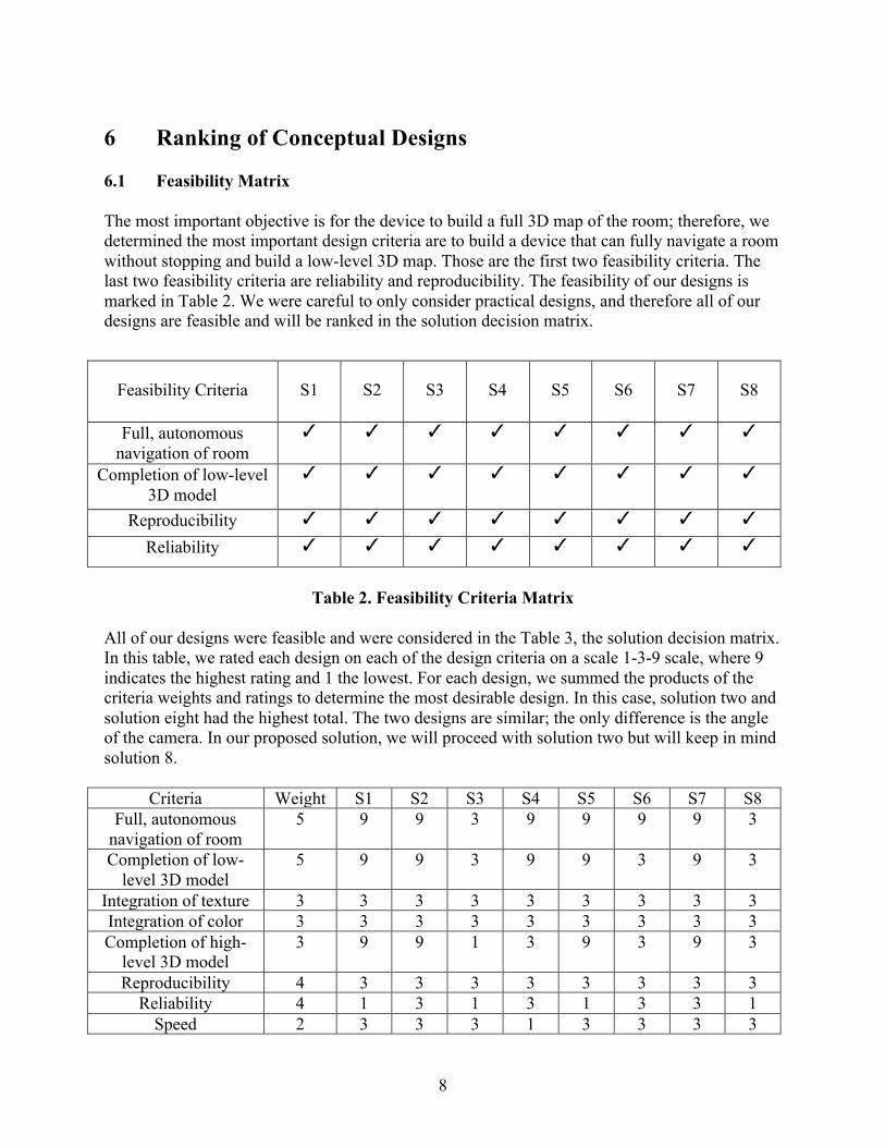
6 Ranking of Conceptual Designs 6.1 Feasibility Matrix The most important objective is for the device to build a full 3D map of the room; therefore, we determined the most important design criteria are to build a device that can fully navigate a room without stopping and build a low-level 3D map. Those are the first two feasibility criteria. The last two feasibility criteria are reliability and reproducibility. The feasibility of our designs is marked in Table 2. We were careful to only consider practical designs, and therefore all of our designs are feasible and will be ranked in the solution decision matrix.
Feasibility Criteria
S1
S2
S3
S4
S5
S6
S7
S8
Full, autonomous navigation of room
✓ ✓ ✓ ✓ ✓ ✓ ✓ ✓
Completion of low-level 3D model
✓ ✓ ✓ ✓ ✓ ✓ ✓ ✓
Reproducibility ✓ ✓ ✓ ✓ ✓ ✓ ✓ ✓
Reliability ✓ ✓ ✓ ✓ ✓ ✓ ✓ ✓
Table 2. Feasibility Criteria Matrix
All of our designs were feasible and were considered in the Table 3, the solution decision matrix. In this table, we rated each design on each of the design criteria on a scale 1-3-9 scale, where 9 indicates the highest rating and 1 the lowest. For each design, we summed the products of the criteria weights and ratings to determine the most desirable design. In this case, solution two and solution eight had the highest total. The two designs are similar; the only difference is the angle of the camera. In our proposed solution, we will proceed with solution two but will keep in mind solution 8.
Criteria Weight S1 S2 S3 S4 S5 S6 S7 S8 Full, autonomous
navigation of room 5 9 9 3 9 9 9 9 3
Completion of low-level 3D model
5 9 9 3 9 9 3 9 3
Integration of texture 3 3 3 3 3 3 3 3 3 Integration of color 3 3 3 3 3 3 3 3 3 Completion of high-
level 3D model 3 9 9 1 3 9 3 9 3
Reproducibility 4 3 3 3 3 3 3 3 3 Reliability 4 1 3 1 3 1 3 3 1
Speed 2 3 3 3 1 3 3 3 3

9
Model Quality 4 9 9 3 3 3 3 9 3 Total - 193 201 85 155 169 129 201 95
Table 3. Solution Decision Matrix
7 Proposed Design Solution 7.1 Overview Our proposed design solution is solution 2, briefly described above. The RGB-Depth camera that we will use is the Microsoft Kinect v2. This camera has a higher image quality and better depth and object recognition than the Kinect v1 [8]. Our navigation robot is the iRobot Create2 Programmable Robot. This robot will give us a platform for the camera that has multiple sensors that will be beneficial to the room mapping process. Additionally, the Create2 design can be modified to give us a stable platform with which we can attach mounting hardware to hold the laptop and Kinect. A detailed description of the solution is given in this section. 7.2 Hardware Due to the fact that the Kinect camera has an individual power supply, the whole system should be wireless. Therefore, we need to solve the power supply problem for the Kinect. Our solution will be to use a combination of 8 to 10 AA batteries to supply the 12 volts input needed for the Kinect 2. A two-level, 1.5-foot holder will be built on top of the iRobot, as seen in Figure 2. The holder will cover the laptop and the Kinect v2 camera will be placed on top of the holder. This arrangement places the camera at a desirable height to collect images.
Figure 2. Structural Design
7.3 Mapping and Localization The choice to use the iRobot Create 2 offers many sensors that can be utilized to effectively map the room, and maneuver around the room even in a cluttered room. The Create 2 can tell when it encounters an object, wall, or drop-off. It also has the ability to keep track of its relative position to where it started, using encounters on the two main drive wheels. To map and localize, a fastSLAM like approach will be used, in which the movement of the Create 2 will be tracked

10
using distance from last measurement data stored by it, and as well as the other sensors onboard to track environmental objects. To keep track of the location of the robot, both the position data from the robot’s sensors and the RGB-Depth camera’s data will be used. The RGB-Depth data will be used in the stitching process, and that will allow the comparison of the current image’s location to that of images next to it. With the location known we can get a course placement for the next image from the camera then match up the image with the 3D model by comparing the data between the two and finding the same structures in both. There will be a default movement strategy that the Create 2 will take. The first default movement strategy will be to move in tight spirals expanding outward. When the device is under going testing this base movement pattern will be optimized so that there will be a default strategy in the final product that can reasonably move the robot until a point where either object avoidance needs to occur or once there are areas that need to be mapped outside of a certain distance around the robot. If the robot is in a position where the default movement pattern becomes beneficial again it will return to that state. We will use the camera to detect areas where the device should not move, and implement collision avoidance procedures as necessary. 7.4 Data Transmission In terms of data transmission for this project, the most effective solution is to wirelessly transmit the data produced by the RGB-Depth camera over a network to an offsite machine for processing. This is due to the relatively weak computational power of the computer onboard the robot as well as the need for complete mobility of the robot. As for the transmission protocol, TCP should suffice, as it offers a level of reliability that is not present with UDP while the relatively slower speed should not be an issue with the amount of data being transmitted. 7.5 Building a 3D Model We will use Kinect Fusion [5,7] to build our 3D model. Kinect Fusion provides 3D model creation and object scanning, and can be used to see a detailed 3D model of a scene [7]. 7.6 High-Level Models A high-level system architecture that details the interactions between the main three components, the robot, camera, and computer, is shown in Figure 3. Next, a high level model of our algorithm is presented in Figure 4.
Camera
Computer Robot

11
Figure 3. High-level system architecture: The camera, robot and computer will interact to build the 3D model. The computer will process information from the camera, transmit
information, and instruct the robot where to move. The robot will be the base for the computer, and will navigate the room for the camera to acquire images. The camera will transmit images to
the computer and will be used to identify objects/areas to avoid.
Figure 4. High-level model of 3D model building algorithm: First, we will power the robot, camera, processing units, and any other necessary devices. The robot will be placed into a room and the mapping procedure will be initiated. The device will collect data from the camera and
Start Power the robot, camera, and
processing units, assemble into one robust structure, and place
in a room
Measurement Capture depth image using
depth camera
Data Transmission Send image data to processing
unit
Model Update Using software, process and
integrate new image data into the 3D model
Collision Avoidance Determine locations that the robot can move to without a
collision
Move Determine and move to the next
location
Rep
eat u
ntil
a 3D
mod
el is
con
fiden
tly c
ompl
eted
12
transmit the data to a processing unit. The processing unit will use the depth image data to estimate the location of the robot and will integrate the data into the 3D model. After updating
the 3D model, the processor will determine any unviable locations for the robot to move. While this is happening, the robot will continue to move and send depth image data during its mapping process, and it will avoid any unviable locations. We will determine a confidence measure that will indicate how certain we are of our model and that the model is complete, and the method
will be completed until we reach a certain confidence threshold in our model.
7.7 Testing and evaluation
The device will be tested by placing it into different rooms and implementing the 3D model building process. We will test at least ten different rooms and will evaluate the ability of the device to satisfy the criteria, including the completion of the model and navigation process and the quality of the model. Different rooms will have different obstacles, and some may be harder to navigate than others. With this testing process we will ensure that the device is reliable and that it satisfies the criteria.
8 Risk Analysis The design problem does not involve many risks, but the risks that it does involve will need to be carefully analyzed and minimized in our design. Some of the risks that will be present are damage to the property in the room, electrical hazards and injury to people if the robot collides with someone. The robot could collide with objects and damage the object. Objects will have to be avoided by use of the robots sensors and cameras. Additionally we would require the use of the device to be supervised by a person to make sure that damage does not occur. For mapping the room we could insure minimal foot traffic while the robot is in the process of mapping. Electrical hazards would be present in any electronic design and caution will be used in the design process. 9 Project Management Plan 9.1 Personnel The team working on this project consists of five members, each of whom have been assigned various technical tasks within the project along with non-technical roles. Jacob Kneibel is responsible for the mapping and localization of the robot in the room, which will include a movement algorithm that the robot will follow throughout the room. Jacob is also responsible for managing presentations for the team. Kexiang Qian is response for the power supply of the Kinect camera, the hold structure building and later time hardware maintenance. Nick Saxton is responsible for researching and implementing the transmission of the sensor data from the onboard computer to the off board computer for computation. Additionally, Nick designed and managed the team’s webpage. Nick Zuzow and David Zoltowski are both responsible for the 3D model building software. More specifically, Nick will be responsible for interfacing between the software and the other devices, while David will be responsible for using the 3D model to detect objects and avoid collisions.
13
9.2 Resources Most of the resources required for this project had to be purchased by the team and our detailed in the budget section below. However, two key components of the solution were acquired through the ECE Department: the onboard laptop computer and the off board computer responsible for handling the computation of the sensor data. Additionally, the team was provided access to the ECE 480 Lab for use as both a workspace and a testing environment. Dr. Daniel Morris, the team’s sponsor, also provided the team with many great ideas for the project. 9.3 Timeline The GANTT chart detailing our proposed schedule for project work and deadlines is shown in Figure 5 and Figure 6.
Figure 5. GANTT Chart Page 1
14
Figure 6. GANTT Chart Page 2
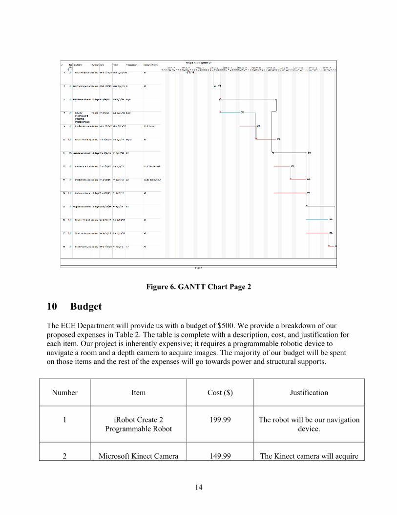
10 Budget The ECE Department will provide us with a budget of $500. We provide a breakdown of our proposed expenses in Table 2. The table is complete with a description, cost, and justification for each item. Our project is inherently expensive; it requires a programmable robotic device to navigate a room and a depth camera to acquire images. The majority of our budget will be spent on those items and the rest of the expenses will go towards power and structural supports.
Number
Item
Cost ($)
Justification
1
iRobot Create 2
Programmable Robot
199.99
The robot will be our navigation
device.
2
Microsoft Kinect Camera
149.99
The Kinect camera will acquire

15
for Xbox v2
rgb-d images.
3
Kinect to Windows adapter
49.99
The adapter will connect the
Kinect camera to our laptop for processing.
4
Power Supplies
79.99
The remaining budget will be
used to power our devices.
Table 4. Budget 11 References [1] Levoy, Marc, et al. "The digital Michelangelo project: 3D scanning of large statues." Proceedings of the 27th annual conference on Computer graphics and interactive techniques. ACM Press/Addison-Wesley Publishing Co., 2000. [2] Pouliquen, Dominique. "It's a Snap! Take a Photograph and Create a 3D Model." Autodesk, Inc.. Web. 20 Feb. 2015. <https://thingiverse-production.s3.amazonaws.com/assets/8a/3e/e6/60/19/catchManual.pdf>. [3] "BIG." Projects. Bristol Interaction and Graphics. Web. 20 Feb. 2015. <http://big.cs.bris.ac.uk/projects/mobile-kinect/>. [4] Montemerlo, Michael, et al. "FastSLAM: A factored solution to the simultaneous localization and mapping problem." AAAI/IAAI. 2002. [5] Newcombe, Richard A., et al. "KinectFusion: Real-time dense surface mapping and tracking." Mixed and augmented reality (ISMAR), 2011 10th IEEE international symposium on. IEEE, 2011. [6] Nießner, Matthias, et al. "Real-time 3d reconstruction at scale using voxel hashing." ACM Transactions on Graphics (TOG) 32.6 (2013): 169. [7] "Kinect Fusion." Kinect Fusion. Microsoft. Web. 14 Feb. 2015. <https://msdn.microsoft.com/en-us/library/dn188670.aspx>. [8] "Kinect for Windows Features." Kinect for Windows Features. Microsoft. Web. 13 Feb. 2015. <http://www.microsoft.com/en-us/kinectforwindows/meetkinect/features.aspx>.