proposal in response to the town of … · a. changes to qualifications since qualification by ccm...
TRANSCRIPT

Bringing passion to light.
SSubmitted to: OOffice of the First Selectman Town of Seymour 1 First Street Seymour, CT 06483 SSubmitted by: Jason Tanko, President Tanko Streetlighting, Inc. 220 Bayshore Blvd. San Francisco, CA 94124 (415) 254-7579 [email protected]
PROPOSAL IN RESPONSE TO THE TOWN OF SEYMOUR’S REQUEST FOR PROPOSAL AND BID FOR MUNICIPAL STREETLIGHT LED RETROFIT, MANAGEMENT, AND MAINTENANCE SERVICES
April 28, 2016
Copyright April 28, 2016
By Tanko Lighting All rights reserved

Page 2 of 33
TOWN OF SEYMOUR | MUNICIPAL STREETLIGHT LED RETROFIT | TANKO LIGHTING
www.tankolighting.com | 220 Bayshore Blvd. | San Francisco, CA 94124 | PP 415.254.7579 | FF 415.822.3626
CCONTENTS Contents .................................................................................................................................................................... 2
Cover Letter ............................................................................................................................................................... 4
I. Proposal Requirements.......................................................................................................................................... 5
A. Changes to Qualifications Since Qualification by CCM RFQ #52014 ............................................................. 5
B. Required Disclosures ......................................................................................................................................... 5
C. Legal Status ........................................................................................................................................................ 6
D. Presumption of Proposer’s Full Knowledge ..................................................................................................... 6
E. Affirmative Action and Equal Opportunity ....................................................................................................... 6
F. Nonresident Real Property Contractors ........................................................................................................... 7
G. Compliance with Immigration Laws ................................................................................................................. 7
H. Non-Collusion Affidavit ..................................................................................................................................... 7
I. Subcontracting .................................................................................................................................................... 8
II. Qualifications ......................................................................................................................................................... 8
A. Description of Firm ............................................................................................................................................ 8
B. Relevant Experience ........................................................................................................................................ 13
C. References........................................................................................................................................................ 15
III. Scope of Work .................................................................................................................................................... 15
Phase 1: Project Development ............................................................................................................................ 15
Task 1: Comprehensive GIS Audit of Existing Streetlights ............................................................................. 16
Task 2: Data Reconciliation .............................................................................................................................. 17
Task 3: Submission of Reconciliation Report to Eversource Energy ............................................................. 17
Task 4: Equipment Selection ........................................................................................................................... 17
Task 5: Replacement Plan ................................................................................................................................ 18
Task 6: Financing Options ................................................................................................................................. 18
Task 7: Development of Project Financial Analysis ........................................................................................ 19
Task 8: Development of Final Scope of Work ................................................................................................. 19
Task 9: Community Outreach and Notification .............................................................................................. 19
Task 10: Implementation Structure and Schedule ......................................................................................... 20
Task 11: Acquisition Assistance ....................................................................................................................... 20
Phase 2: Project Implementation ........................................................................................................................ 20
Task 1: Materials Procurement ....................................................................................................................... 20

Page 3 of 33
TOWN OF SEYMOUR | MUNICIPAL STREETLIGHT LED RETROFIT | TANKO LIGHTING
www.tankolighting.com | 220 Bayshore Blvd. | San Francisco, CA 94124 | PP 415.254.7579 | FF 415.822.3626
Task 2: Local Subcontractor Selection ............................................................................................................ 21
Task 3: Final Project Review with Eversource ................................................................................................ 22
Task 4: Logistics Management ........................................................................................................................ 22
Task 5: Waste Disposal .................................................................................................................................... 22
Task 6: Installation ........................................................................................................................................... 22
Task 7: Commissioning .................................................................................................................................... 23
Task 8: Progress Reporting .............................................................................................................................. 24
Phase 3: Project Closeout and Deliverables ....................................................................................................... 24
Task 1: Rebate & Tariff Change Coordination ................................................................................................ 24
Task 2: Photometric Confirmation .................................................................................................................. 24
Task 3: Final Reporting..................................................................................................................................... 25
Phase 4: System Maintenance ............................................................................................................................ 25
Task 1: Finalized Estimated Costs ................................................................................................................... 25
Task 2: Finalized Maintenance Contract ......................................................................................................... 25
Task 3: Pre-LED Conversion Maintenance Services ....................................................................................... 26
Task 4: Post-LED Conversion Maintenance Services ...................................................................................... 28
IV. LED Replacement, Project Savings & Project Costs ......................................................................................... 31
V. Bid Form .............................................................................................................................................................. 32
VI. Additional Funding Options ............................................................................................................................... 32
VII. Appendices ........................................................................................................................................................ 33
Appendix A – Required Corporate Information Forms .............................................................................. 33
Appendix B – Non-Collusion Affidavit ......................................................................................................... 33
Appendix C – Sample Weekly Audit Report ............................................................................................... 33
Appendix D – Sample Weekly Installation Report ..................................................................................... 33
Appendix E – Bid Form ................................................................................................................................ 33
Appendix F – Project Savings & Cost Summary ......................................................................................... 33
Appendix G – Product Technical Specifications ......................................................................................... 33

Page 4 of 33
TOWN OF SEYMOUR | MUNICIPAL STREETLIGHT LED RETROFIT | TANKO LIGHTING
www.tankolighting.com | 220 Bayshore Blvd. | San Francisco, CA 94124 | PP 415.254.7579 | FF 415.822.3626
CCOVER LETTER April 28, 2016 Office of the First Selectman Town of Seymour 1 First Street Seymour, CT 06483 Dear Office of the First Selectman, Tanko Streetlighting, Inc. (“Tanko Lighting”) appreciates the opportunity to submit for your review this proposal in response to the Town of Seymour’s Request for Proposal and Bid for Municipal Streetlight LED Retrofit, Management and Maintenance Services. Tanko Lighting understands the Town’s desire to verify streetlighting luminaire and pole asset inventory, complete a retrofit program that will convert the approximately 1,131 existing luminaires to LED technology luminaires, and establish a streetlighting system management and maintenance service program. In response, Tanko Lighting has assembled a dynamic team of talented professionals with a comprehensive approach. Tanko Lighting’s extensive knowledge of and experience with streetlighting conversion projects is unsurpassed. The company has previously been or is currently involved with the energy efficiency conversion of more than 200,000 streetlights throughout the nation. Tanko Lighting is distinguished from other competitors by its passionate and sole focus on streetlighting, which enables it to be steeped in the necessary technical knowledge and market context of municipal streetlighting projects. Tanko Lighting will serve as the prime contractor for project, responsible for contract oversight, audit, data reconciliation, design, procurement, installation coordination, commissioning, data reporting and coordination of maintenance services. Tanko Lighting will partner with a qualified local electrical contractor to perform the installation and maintenance services for the project. Tanko Lighting has extensive experience with municipal streetlight LED conversion projects in the State of Connecticut. As a member and qualified service provider for the Connecticut Conference of Municipalities (CCM), Tanko Lighting’s qualifications have already been thoroughly vetted in the State of Connecticut – by both the CCM and by the many municipalities within Connecticut with which Tanko Lighting is already in contract for similar projects (including the Towns of Rocky Hill, Berlin, Vernon, New London, West Hartford, and the Borough of Jewett City). As such, Tanko Lighting is significantly qualified to ensure that the Town of Seymour’s LED streetlight conversion and maintenance results in accessible, efficient, accurate, cost effective and ultimately expedited project execution that will provide unparalleled value for the Town and will ensure the success of this project. Please let us know should you have any questions. We look forward to your feedback. Regards, Jason Tanko President Enclosures

Page 5 of 33
TOWN OF SEYMOUR | MUNICIPAL STREETLIGHT LED RETROFIT | TANKO LIGHTING
www.tankolighting.com | 220 Bayshore Blvd. | San Francisco, CA 94124 | PP 415.254.7579 | FF 415.822.3626
II. PROPOSAL REQUIREMENTS
A. Changes to Qualifications Since Qualification by CCM RFQ #52014 It is the responsibility of the Proposer to update and identify any changes to the Proposers’ qualifications or legal status which may have occurred since qualification by CCM RFQ # 52014. Since being qualified by CCM, Tanko Lighting has been involved with several municipalities in the State of Connecticut for turn-key LED streetlight acquisition, conversion and maintenance projects, including:
New London, CT (3,500 fixtures) – Turn-key LED Conversion Berlin, CT (2,500 fixtures) – Acquisition Support, Turn-key LED Conversion, Maintenance Rocky Hill, CT (1,600 fixtures) – Acquisition Support, Turn-key LED Conversion, Maintenance Vernon, CT (1,700 fixtures) – Acquisition Support, Turn-key LED Conversion, Maintenance West Hartford, CT (6,000 fixtures) – Turn-key LED Conversion Jewett City, CT (300 fixtures) – Turn-key LED Conversion East Lyme, CT (1,500 fixtures) – Audit/Design of LED Conversion Wolcott, CT (980 fixtures) – Turn-key LED Conversion
Further, Tanko Lighting has been involved with the following projects in the Northeast since being qualified by CCM, including:
Goffstown, NH (460 fixtures) – Turn-key LED Conversion North Stratford, NH (50 fixtures) – Turn-key LED Conversion Warren, MA (430 fixtures) – Acquisition Support, Turn-key LED Conversion Somerville, MA (5,000 fixtures) – Turn-key LED Conversion Malden, MA (3,500 fixtures) – Turn-key LED Conversion Lowell, MA (8,500 fixtures) – Turn-key LED Conversion Sudbury, MA (500 fixtures) – Turn-key LED Conversion Millis, MA (500 fixtures) – Turn-key LED Conversion Hopkinton, MA (500 fixtures) – Turn-key LED Conversion Westfield, MA (4,000 fixtures) – Design Services Burlington, MA (2,500 fixtures) – Turn-key LED Conversion Andover, MA (1,500 fixtures) – Turn-key LED Conversion Leominster, MA (3,573 fixtures) – Turn-key LED Conversion Everett, MA (3,333 fixtures) – Turn-key LED Conversion Wayland, MA (700 fixtures) – Turn-key LED Conversion Watertown, MA (800 fixtures) – Turn-key LED Conversion
B. Required Disclosures In its proposal each proposer must disclose, if applicable: • Its inability or unwillingness to meet any requirement of this RFP. Tanko Lighting is able and willing to meet all requirements of the Town’s RFP. • If it is listed on the State of Connecticut's Debarment List.

Page 6 of 33
TOWN OF SEYMOUR | MUNICIPAL STREETLIGHT LED RETROFIT | TANKO LIGHTING
www.tankolighting.com | 220 Bayshore Blvd. | San Francisco, CA 94124 | PP 415.254.7579 | FF 415.822.3626
Tanko Lighting is not listed on the State of Connecticut’s Debarment List. • If it is ineligible, pursuant to Conn. Gen. Stat. § 31-57b, to be awarded a contract because of occupational safety and health law violations. Tanko Lighting has never experienced any occupational safety and health law violations. • All resolved and pending arbitrations and litigation matters in which the proposer or any of its principals (regardless of their place of employment) have been involved within the last ten (I0) years. Tanko Lighting and its principals have zero pending arbitrations and litigation matters. • All criminal proceedings in which the proposer or any of its principals (regardless of their Place of employment) has ever been the subject. Tanko Lighting, nor any of its principals, has ever been the subject of criminal proceedings. • Each instance in which it or any of its principals (regardless of their place of employment) have ever been found to have violated any state or local ethics standard or to have committed any other offense arising out of the submission of proposals or bids, or the performance of work on public works projects or contracts. A proposer's acceptability based on these disclosures lies solely in Town's discretion. Tanko Lighting, nor any of its principals, have ever been found to have violated any state or local ethics standard, or have committed any other offense arising out of the submission or proposals or bids, or the performance of work on public works projects or contracts.
C. Legal Status If a proposer is a corporation, limited liability company or other business entity that is required to register with the Connecticut Secretary of the State's Office, it must have a current registration to do business in the State of Connecticut that is on file with that office. The Town may, in its sole discretion, request acceptable evidence of any proposer's legal status. Tanko Streetlighting, Inc. (Tanko Lighting) is a privately-owned S Corporation, registered in the State of California. It is currently registered as a Foreign Corporation with the State of Connecticut Secretary of State’s Office and can provide evidence of this status at the Town’s request.
D. Presumption of Proposer’s Full Knowledge Each proposer is responsible for having read and understood each document in this RFP and any addenda issued by the Town. A proposer's failure to have reviewed all information that is part of or applicable to this RFP shall in no way relieve it from any aspect of its proposal or the obligations related thereto. Each proposer is deemed to be familiar with and is required to comply with all federal, state and local laws, ordinances and regulations that in any manner relate to the RFP or the performance of the work described therein. By submitting a proposal, each proposer represents that it has thoroughly examined and become familiar with the scope of work outlined in the RFP, and it is capable of performing the work to achieve the Town's objectives. By submitting this proposal, Tanko Lighting represents that it has thoroughly examined and become familiar with the scope of work outlined in the RFP, and it is capable of performing the work to achieve the Town’s objectives.
E. Affirmative Action and Equal Opportunity Each proposer must submit a completed Certification of Affirmative Action Program form included with this RFP. Proposers with fewer than ten (I0) employees should indicate that fact on the Certification form and return the form with their proposal.

Page 7 of 33
TOWN OF SEYMOUR | MUNICIPAL STREETLIGHT LED RETROFIT | TANKO LIGHTING
www.tankolighting.com | 220 Bayshore Blvd. | San Francisco, CA 94124 | PP 415.254.7579 | FF 415.822.3626
Although the Town’s RFP stated that the Certification of Affirmative Action Program form was required, the form was not included in the RFP documents. Tanko Lighting can provide this to the Town once the Town provides the appropriate required form.
F. Nonresident Real Property Contractors If the successful proposer is a "nonresident contractor" as defined in Conn. Gen. Stat. § 12430(7)(A) as amended, it shall comply fully with the provisions of§ 12-430(7) and, prior to execution of any contract for the services described in the RFP, shall furnish the municipality with a copy of the requisite certificate of compliance set forth in § 12-430(7)(E). Each successful proposer agrees to defend, indemnify, and hold harmless the Town, and its employees, officers, officials, agents, volunteers and independent contractors, including any of the foregoing sued as individuals (collectively, the "Town Indemnified Parties"), from any and all taxes, interest and penalties that the State of Connecticut asserts are due with respect to the successful proposer's activities under any such contract. Each successful proposer shall also be required to pay any and all attorney's fees incurred by The Town Indemnified Parties in enforcing any of the successful proposer's obligations under this section, whether or not a lawsuit is commenced, which obligations shall survive the termination or expiration of any contract for the services described in the RFP. Tanko Lighting is considered a “nonresident contractor” and will provide to the Town a copy of its requisite certificate of compliance prior to execution of any contract for the services described in the Town’s RFP.
G. Compliance with Immigration Laws By submitting a proposal, each proposer confirms that it has complied, and during the term of any contract will comply, with the Immigration Reform and Control Act ("IRCA") and that each person it provides under any such contract will at all times be authorized for employment in the United States of America. Each proposer confirms that it has a properly completed Employment Eligibility Verification, Form I-9 for each person who will be assigned under any such contract and that it will require each subcontractor, if any, to confirm that it has a properly completed Form I-9 for each person who will be assigned. A successful proposer shall defend, indemnify, and hold harmless the Town, its employees, officers, officials, agents, volunteers and independent contractors, including any of the foregoing sued as individuals (collectively, the "Town Indemnified Parties"), against any and all proceedings, suits, actions, claims, damages, injuries, awards, judgments, losses or expenses, including fines, penalties, punitive damages, attorney's fees and costs, brought or assessed against, or incurred by, Town Indemnified Parties related to or arising from CCM RFQ 52014 pg. 7 the obligations under IRCA imposed upon the successful proposer or its subcontractor. The successful proposer shall also be required to pay any and all attorney's fees and costs incurred by Town Indemnified Parties in enforcing any successful proposer's obligations under this provision, whether or not a lawsuit is commenced, which obligations shall survive the termination or expiration of any contract. By submitting this proposal, Tanko Lighting confirms that it has complied, and during the term of any contract will comply, with the Immigration Reform and Control Act ("IRCA") and that each person it provides under any such contract will at all times be authorized for employment in the United States of America. Tanko Lighting also confirms that it has a properly completed Employment Eligibility Verification, Form I-9 for each person who will be assigned under any such contract and that it will require each subcontractor, if any, to confirm that it has a properly completed Form I-9 for each person who will be assigned.
H. Non-Collusion Affidavit Each proposer shall submit a completed Non Collusion Affidavit that is part of this RFP. Please find Tanko Lighting’s completed Non Collusion Affidavit in Appendix B.

Page 8 of 33
TOWN OF SEYMOUR | MUNICIPAL STREETLIGHT LED RETROFIT | TANKO LIGHTING
www.tankolighting.com | 220 Bayshore Blvd. | San Francisco, CA 94124 | PP 415.254.7579 | FF 415.822.3626
I. Subcontracting The Town prefers the local economy to benefit from this project. The proposal shall explain the Firm's plans to solicit bids from Seymour area qualified subcontractors contractors. Prior to entering into any subcontract agreement(s) for the work described in the contract, the successful proposer shall provide the municipality with written notice of the identity (the Subcontractor's full legal name, street address, mailing address (if different from street address), and telephone number) of each proposed subcontractor. The municipality shall have the right to object to any proposed subcontractor by providing the successful proposer with written notice thereof within seven (7) business days of receipt of all required information about the proposed subcontractor. If the municipality objects to a proposed subcontractor, the successful proposer shall not use that subcontractor for any portion of the work described in the contract. All permitted subcontracting shall be subject to the same terms and conditions as are applicable to the successful proposer. The successful proposer shall remain fully and solely liable and responsible to the municipality for performance of the work described in the contract. The successful proposer also agrees to promptly pay each of its subcontractors within thirty (30) days of receipt of payment from the municipality or otherwise in accordance with law. The successful proposer shall assure compliance with all requirements of the contract. The successful proposer shall also be fully and solely responsible to the municipality for the acts and omissions of its subcontractors and of persons, whether directly or indirectly employed by the subcontractor(s), as the successful proposer is for the acts or omissions of the persons it employs directly. Tanko Lighting routinely partners with subcontractors for installation for its turn-key municipal streetlighting projects. Tanko Lighting contends that this is an ideal way to utilize local knowledge and leverage taxpayer dollars back to the local economy. As such, Tanko Lighting is very familiar with how to properly solicit, vet and manage qualified local subcontractors. For the Town’s project, Tanko Lighting has preliminarily identified a pool of qualified, local subcontractors, including Signature Electric Services and New England Electric. Tanko Lighting will solicit additional local firms, review a variety of factors, including price, qualifications, availability of crews, responsiveness and will vet all of the possible subcontractors with Town staff and ensure that the selected subcontractor for the project’s installation scope of work is qualified, with the experienced field labor necessary for the project. The selected subcontractor will provide installation, traffic control support, environmental disposal, and maintenance services for this project. The selected subcontractor’s efforts will be directed by a Project Manager, who will be responsible for all logistics and field installation, including safety and traffic control, and all management of field staff. The selected subcontractor will have ample local storage facilities from which to safely store all equipment and materials needed for this project. Further, the selected contractor will utilize equipment, such as bucket trucks, traffic control signage, etc. necessary for a quality and safe installation. Finally, the selected subcontractor will have experience with municipal lighting projects and qualified staff highly-trained in the nuances of electrical installation work and safety. Tanko Lighting will ensure that all of the Town’s subcontractor requirements (as noted in the Town’s RFP) are met. For more information on Tanko Lighting’s approach to soliciting a qualified subcontractor for this project, please see the Phase 2: Project Implementation section.
III. QUALIFICATIONS
A. Description of Firm Since 2003, Tanko Lighting has been assisting municipalities with their streetlighting needs and is a national firm focused solely on providing professional services for turn-key municipal streetlighting conversion projects.

Page 9 of 33
TOWN OF SEYMOUR | MUNICIPAL STREETLIGHT LED RETROFIT | TANKO LIGHTING
www.tankolighting.com | 220 Bayshore Blvd. | San Francisco, CA 94124 | PP 415.254.7579 | FF 415.822.3626
Tanko Lighting is a privately held S Corporation and holds electrical contractor licenses in the States of California and Arizona. Additionally, Tanko Lighting is a Certified Contractor by the Commonwealth of Massachusetts’ Division of Capital Management and Maintenance (DCAMM), a Qualified Vendor with the Connecticut Conference of Municipalities, and is a registered Energy Services Company (ESCO) with the United States Department of Energy. Tanko Lighting is focused exclusively on municipal energy efficiency streetlighting conversion projects. With decades of experience serving this market, Tanko Lighting is the municipal streetlight expert. Because of its technical experience and national context, Tanko Lighting is intimately familiar with industry standards and trends, as well as municipalities’ challenges with aging infrastructure. Given its extensive project experience, Tanko Lighting is uniquely positioned to assist the Town of Seymour with this project for the following reasons: Municipal Streetlight Conversion Experience Tanko Lighting’s extensive knowledge of and experience with streetlighting conversion projects is unsurpassed. The company has previously been or is currently involved with the energy efficiency conversion of more than 200,000 streetlights nationwide. Project Management Experience Tanko Lighting utilizes the extensive experience and organizational skills of its in-house project managers to develop project timelines, and manage ordering and installation schedules. This ability to focus managing all aspects of the project is in contrast to many of its competitors, which typically operate projects according to crew schedules as the priority and not necessarily prioritizing the Town’s schedule. Technical Knowledge Tanko Lighting has significant technical expertise centered on municipal streetlighting infrastructure. Led by an electrical engineer and licensed electrical contractor, Jason Tanko (President), Tanko Lighting understands the field conditions and system constraints that are often involved with municipal streetlighting projects – including projects involving aged infrastructure. This enables the team to accurately design projects to prevent anticipated challenges, as well as quickly respond with streamlined solutions in the event of technical difficulties during a project. National Context Tanko Lighting’s broad experience with feasibility, and design and implementation of LED conversion projects provides tremendous national context that will benefit the Town by ensuring that the project is consistent with industry standards during each phase of the project. Data Management Tanko Lighting contends that utilizing data collection and analysis throughout all stages of a project results in superior project management. Thus, Tanko Lighting has built its own in-house data team with the right blend of both streetlighting technical expertise and data analysis skills to collect and reconcile accurate project data. While competitors often subcontract data collection and management, Tanko Lighting retains these activities in-house to better inform the design and project management processes. Field staff are provided devices that track the Global Position System (GPS) coordinates and other characteristics of the existing fixtures for the audit phase, as well as for the installation phase (installers track this information at the time of the LED installation), which, when compared with Town data, streamlines the accuracy of the ordering and installation processes. Additionally, Tanko Lighting utilizes the most state-of-the-art technology, with spatial accuracy within +/- one meter (compared with many competitors whose devices have a margin of error of up to fifteen feet), and utilizes the industry standard software – ESRI’s ArcGIS – to process data

Page 10 of 33
TOWN OF SEYMOUR | MUNICIPAL STREETLIGHT LED RETROFIT | TANKO LIGHTING
www.tankolighting.com | 220 Bayshore Blvd. | San Francisco, CA 94124 | PP 415.254.7579 | FF 415.822.3626
and provide shape files that are fully compatible with clients’ GIS records. Further, Tanko Lighting’s field auditors have accurately collected data on tens of thousands of streetlight fixtures – ensuring that the Town’s audit will be conducted by highly qualified professionals with tremendous field experience. As a result, Tanko Lighting’s projects are well-designed, streamlined, accurate, efficient and cost effective. Additionally, Tanko Lighting’s focus on data results in significant transparency throughout all phases of the project. Data Reconciliation Reconciling the audit data with existing Town records is critical to providing an accurate final existing inventory. In Tanko Lighting’s experience, most initial utility inventory records are highly inaccurate, which can lead to overstating or understating the quantity of existing assets. In countless projects, Tanko Lighting has demonstrated its ability to reconcile audit data, as well as provide substantiated evidence to utility companies when field conditions vary from initial utility-provided inventory records. LED Conversion Design Any consultant can select streetlight fixtures from a catalog, but only an expert can walk the Town through its specific nuances and existing field conditions that warrant a customized approach to design. As a streetlight expert, Tanko Lighting is equipped to provide a comprehensive approach to the design process. Because Tanko Lighting is involved with turn-key LED streetlight conversion projects nationwide, it has tremendous context from which to base its LED design recommendations. Tanko Lighting is product agnostic and has worked with all the major LED streetlight manufacturers, including cobra head, as well as decorative products. Yet, Tanko Lighting does not merely rely on manufacturers for information related to design, but has the knowledge and analyzation skills to interpret how manufacturer data impacts a Town’s needs. Tanko Lighting utilizes industry standards – which typically involves organizing the existing streetlight infrastructure by road classification (e.g. arterial, collector, residential streets) and applying standard LED replacement wattage recommendations based on the location of each existing HPS fixture. Additionally, Tanko Lighting considers areas of concern that are currently over or under-lit and applies customized solutions to these locations so that a Town’s conversion project results in a comprehensive re-design that is updated to the existing field conditions and needs of the Town’s current system. This is in contrast with Tanko Lighting’s competitors, which often merely apply a cookie cutter approach to design that oversimplifies areas that are currently being over or under-lit. Selective Subcontracting Tanko Lighting is highly aware of its core competencies. It thus retains the essential project activities (such as design, engineering, data collection/reconciliation, product procurement and project management) in-house in order to ensure that the project is run cost-effectively, efficiently and successfully. Tanko Lighting practices selective subcontracting, in that it sources out limited key project activities (such as installation and maintenance) to qualified streetlight experts local to the project in order to obtain competitive pricing and prevent the project from accruing unnecessary costs and change orders. Further, selective subcontracting allows Tanko Lighting the flexibility to obtain additional installation resources as needed, and also allows the Town to invest in the local economy and leverage local expertise by including local subcontractors in the project. Experience with Financing Coordination Tanko Lighting has worked on numerous contracts in which it has facilitated project financing for municipal streetlighting projects, including both public (via municipal bonds) and private financing. Tanko Lighting has assisted municipalities by providing an investment grade audit, determining project costs, life cycle costs, savings models, and payback schedules, as well as directly coordinating with the financing entity and the municipality, providing documentation, and reporting about project progress to the financing entity. When public financing is not readily available, Tanko Lighting facilitates private financing through third party entities (such as Graybar Financial Services, TCF Equipment Financing, and Banc of America Public

Page 11 of 33
TOWN OF SEYMOUR | MUNICIPAL STREETLIGHT LED RETROFIT | TANKO LIGHTING
www.tankolighting.com | 220 Bayshore Blvd. | San Francisco, CA 94124 | PP 415.254.7579 | FF 415.822.3626
Capital Corp), which typically offer low-interest, Tax Exempt Lease Purchase financing that includes all costs related to the project, which are repaid through the project’s savings. Further, virtually all of Tanko Lighting’s projects involve rebates from the local utility. Tanko Lighting can leverage this experience nationally – and particularly in Connecticut, to identify potential financing options for this project. Accessibility As a mid-sized firm, Tanko Lighting provides its municipal clients with all of the necessary resources to successfully accomplish complex streetlighting projects – without the challenges of a large, bureaucratic firm. This enables every client to receive personal attention, with a primary Tanko Lighting point of contact providing superior customer service through responsiveness, accessibility, and the agility to create expedited decisions and solutions leading to effective results. Further, Tanko Lighting’s size enables all clients to have direct access to the company’s President, Jason Tanko, at any point during the project – which results in clients having an industry expert available at their fingertips. Experience with Acquisition Projects There is a growing nationwide industry trend in which municipalities are acquiring their streetlight infrastructure from their local private utility companies. This poses tremendous advantages to the municipality, in that not only does it allow the municipality to control the management of the system within its geographic borders, but it also involves tremendous cost savings – particularly related to maintenance and energy (as many utilities charge exorbitant fees for energy and maintenance rates for the systems). Further, once a municipality acquires its system, it has the ability to reap additional savings benefits by converting to LED fixtures. As a result of the significant benefits that municipal acquisitions of streetlight systems provide, Tanko Lighting has been working with a number of municipalities nationwide to assist in their streetlight acquisition strategies. Its experience with acquisitions includes the following:
Vernon, CT: Tanko Lighting is currently assisting the Town of Vernon, CT with a turn-key LED streetlight conversion project – the first phase of which involved a GIS audit, data reconciliation, preliminary design, and acquisition assistance – including valuation support and Town negotiations, and financial feasibility analysis. The project is now moving into Phase 2, which is acquisition and LED conversion implementation – which Tanko Lighting is managing.
Berlin, CT: Tanko Lighting is currently assisting the Town of Berlin, CT with a turn-key LED streetlight conversion project – the first phase of which involved a GIS audit, data reconciliation, preliminary design, and acquisition assistance – including valuation support and Town negotiations, and financial feasibility analysis. The project is now moving into Phase 2, which is acquisition and LED conversion implementation – which Tanko Lighting is managing.
Rocky Hill, CT: Tanko Lighting is currently assisting the Town of Rocky Hill, CT with a turn-key LED streetlight conversion project – the first phase of which involved a GIS audit, data reconciliation, preliminary design, and acquisition assistance – including valuation support and Town negotiations, and financial feasibility analysis. The project is now moving into Phase 2, acquisition and LED conversion implementation – which Tanko Lighting is managing.
East Lyme, CT: Tanko Lighting is currently assisting the Town of East Lyme, CT with a turn-key LED streetlight conversion project – the first phase of which involves a GIS audit, data reconciliation, preliminary design, and acquisition assistance – including valuation support and Town negotiations, and financial feasibility analysis. Once the first phase is complete, the project will move into Phase 2, acquisition and LED conversion implementation – which Tanko Lighting will manage.
West Hollywood, CA: Tanko Lighting is currently the prime consultant providing acquisition and LED conversion support services to the City of West Hollywood, CA. It completed a comprehensive audit for the City,

Page 12 of 33
TOWN OF SEYMOUR | MUNICIPAL STREETLIGHT LED RETROFIT | TANKO LIGHTING
www.tankolighting.com | 220 Bayshore Blvd. | San Francisco, CA 94124 | PP 415.254.7579 | FF 415.822.3626
accompanied the City’s utility on a sampling phase of the City’s infrastructure, and recently developed the strategy, on behalf of the City, with justification and messaging to refute elements of the utility’s initial valuation. Tanko Lighting will continue to coordinate on behalf of the City of West Hollywood with its utility to negotiate a fair purchase price for the City, as well as assist with the California Public Utilities Commission (CPUC) filings. (It should be noted that Tanko Lighting successfully negotiated a comprehensive approach to acquisition, instead of SCE’s piecemeal approach that would have made the City purchase chunks of the system spread out over time. Its approach was agreed to by SCE, ultimately saving the City time and money on the transfer of their assets.) Once the acquisition is completed, Tanko Lighting will assist the City with a conversion to LED fixtures, as well as identify and replace any immediate additional infrastructure needs (such as damaged poles).
Santa Ana, CA: Tanko Lighting is currently the prime consultant providing acquisition and LED conversion support services to the City of Santa Ana, CA. Tanko Lighting recently completed a comprehensive audit for the City and accompanied the utility on a sampling phase of the City’s infrastructure. Tanko Lighting is coordinating on behalf of the City of Santa Ana with the utility to negotiate a fair purchase price for the City, as well as assisting with the California Public Utilities Commission (CPUC) filings. (It should be noted that Tanko Lighting successfully negotiated a comprehensive approach to acquisition, instead of SCE’s piecemeal approach that would have made the City purchase chunks of the system spread out over time. Its approach was agreed to by SCE, ultimately saving the City time and money on the transfer of their assets.) Once the acquisition is completed, Tanko Lighting will assist the City with a conversion to LED fixtures.
Orange, CA: Tanko Lighting is was recently awarded a contract to assist the City of Orange with analyzing the feasibility of an acquisition of its streetlights from Southern California Edison and subsequent LED conversion.
Tustin, CA: Tanko Lighting is currently negotiating a contract with the City of Tustin to serve as the prime consultant providing acquisition and LED conversion support services to the City.
Projects in Massachusetts: Tanko Lighting is currently assisting several municipalities in the Commonwealth of Massachusetts that recently completed acquisitions, including the Towns of Andover, MA, Leominster, MA, Everett, MA, and Warren, MA.
Buffalo, NY: Tanko Lighting was recently awarded a contract to assist the City of Buffalo with its feasibility analysis to determine whether or not it is in the City’s best interest to acquire its streetlighting assets from National Grid and convert to LED fixtures. Tanko Lighting will soon commence a data gap audit of the City, as well as additional financial and baseline assessments to complete the project.

Page 13 of 33
TOWN OF SEYMOUR | MUNICIPAL STREETLIGHT LED RETROFIT | TANKO LIGHTING
www.tankolighting.com | 220 Bayshore Blvd. | San Francisco, CA 94124 | PP 415.254.7579 | FF 415.822.3626
B. Relevant Experience Since 2003, Tanko Lighting has assisted municipalities with their streetlighting needs and is a national firm focused solely on providing professional services for turn-key municipal energy efficiency streetlighting conversion projects.
Tanko Lighting has previously been or is currently involved with the turn-key conversion of more than 200,000 streetlights throughout the nation. Recent projects include:
Specific examples of Tanko Lighting’s recent turn-key projects include:
New London, CT: Tanko Lighting is currently assisting the City of New London, CT with a turn-key LED streetlight conversion project. Tanko Lighting completed an audit, design, equipment selection and is currently in the installation phase of the project. It expects to complete the project by May 2016.
West Hartford, CT: Tanko Lighting is currently assisting the City of West Hartford, CT with a turn-key LED streetlight conversion project. Tanko Lighting completed an audit, design, equipment selection and is currently in the installation phase of the project. It expects to complete the project by May 2016.

Page 14 of 33
TOWN OF SEYMOUR | MUNICIPAL STREETLIGHT LED RETROFIT | TANKO LIGHTING
www.tankolighting.com | 220 Bayshore Blvd. | San Francisco, CA 94124 | PP 415.254.7579 | FF 415.822.3626
Berkeley, CA: Tanko Lighting provided the City of Berkeley with turn-key support to implement its comprehensive streetlight conversion project. This complex project included a total of more than 8,000 fixtures, 6,800 of which were cobra head fixtures and approximately 1,200 were more than twenty-one different styles of decorative fixtures. Tanko Lighting provided project management support, engineering services (including a comprehensive neighborhood design/value engineering phase that updated the fixture design to be more consistent with current field conditions, which resulted in an increase of approximately twenty-five percent of energy savings from original project design estimates), cost-benefit analysis of various technologies, field light measurement analyses, GIS field auditing and commissioning, product procurement, pole tagging, environmental disposal/recycling, data reconciliation, installation management, rebate/rate change support, reporting for available State financing, and administrative services.
Modesto, CA: Tanko Lighting provided the City of Modesto with turn-key support to implement its comprehensive streetlight conversion project of approximately 9,800 cobra head fixtures. Tanko Lighting provided project management support, engineering services (including a comprehensive neighborhood design/value engineering phase that updated the fixture design to be more consistent with current field conditions, which resulted in an increase of approximately ten percent of energy savings from original project design estimates), implementation of an entirely new numbering/tagging system, cost-benefit analysis of various technologies, field light measurement analyses, GIS field auditing and commissioning, product procurement, environmental disposal/recycling, data reconciliation, installation management, rebate/rate change support, and administrative services.
Vallejo, CA: Tanko Lighting provided the City of Vallejo with turn-key support to implement its comprehensive streetlight conversion project of approximately 9,000 cobra head fixtures, utilizing City crews for installation. Tanko Lighting provided project management support, engineering services (including a comprehensive neighborhood design/value engineering phase that updated the fixture design to be more consistent with current field conditions, which resulted in an increase of approximately forty percent of energy savings from original project design estimates), pole tagging, cost-benefit analysis of various technologies, field light measurement analyses, GIS field auditing and commissioning, product procurement, environmental disposal/recycling, data reconciliation, installation management, rebate/rate change support, and administrative services. Tanko Lighting also provided logistics support to assist the City’s own installation crews.
Kauai Island Utility Cooperative (Kauai, HI): Tanko Lighting recently completed Phase 1 of a turn-key project with Kauai Island Utility Cooperative by providing a comprehensive GIS audit of the existing streetlight inventory, as well as data reconciliation, equipment recommendations, design/replacement plan, and cost/savings estimates. The results of these recommendations led to Phase 2 of the project – LED conversion, which Tanko Lighting is currently project managing
Silicon Valley Power (Santa Clara, CA): Tanko Lighting recently completed a turn-key project with Silicon Valley Power by providing a comprehensive GIS audit of the existing streetlight inventory, as well as data reconciliation, equipment recommendations, design/replacement plan, cost/savings estimates, product procurement, installation coordination, stakeholder outreach, commissioning, rebate/rate change coordination, and reporting.
Warren, MA: Tanko Lighting is currently assisting the Town of Warren, MA with a turn-key LED streetlight conversion project – the first phase of which involved a GIS audit, data reconciliation, design, cost/savings estimates, and acquisition assistance – including valuation support and Town negotiations, and financial feasibility analysis.

Page 15 of 33
TOWN OF SEYMOUR | MUNICIPAL STREETLIGHT LED RETROFIT | TANKO LIGHTING
www.tankolighting.com | 220 Bayshore Blvd. | San Francisco, CA 94124 | PP 415.254.7579 | FF 415.822.3626
C. References Please find Tanko Lighting’s relevant references below. Town of West Hartford, CT Reference: Mark Hallenbeck, Manager, Traffic and Safety
Address: 50 South Main Street, West Hartford, CT 06107 Phone: (860) 561-8109 Email: [email protected]
Town of Berlin, CT Reference: Jim Wren, Director of Finance
Address: 240 Kensington Road, Berlin, CT 06037 Phone: (860) 828-7044 Email: [email protected]
Town of Vernon, CT Reference: Robert Kleinhans, Director of Public Works
Address: 14 Park Place, Vernon, CT 06066 Phone: (860) 870-3500 Email: [email protected]
Town of Rocky Hill, CT Reference: Glenn Parent, Director of Public Works
Address: 761 Old Main Street, Rocky Hill, CT 06447 Phone: (860) 258-7709 Email: [email protected]
City of Meriden, CT Reference: Steve Montemurro, Director/Energy Commission Lead
Address: 142 East Main Street, Meriden, CT 06450 Phone: (203) 630-4147 Email: [email protected]
IIII. SCOPE OF WORK Tanko Lighting understands the Town’s desire to select a partner that can assist with acquisition of the streetlight inventory in the Town from Eversource, as well as the most cost-effective opportunities to upgrade and maintain those streetlights to provide energy savings to the Town. In response, Tanko Lighting will provide the following services to assist the Town with achieving its goals for this project.
Phase 1: Project Development This task is paramount to the Town effectively understanding its current infrastructure and appropriately planning so that the LED conversion project maximizes savings. To that end, Tanko Lighting will offer strategic planning services and analysis to ensure that this task accurately establishes the needs and scope of the entire project and minimizes the need for costly change orders and delays. Task 1 will include the following activities:

Page 16 of 33
TOWN OF SEYMOUR | MUNICIPAL STREETLIGHT LED RETROFIT | TANKO LIGHTING
www.tankolighting.com | 220 Bayshore Blvd. | San Francisco, CA 94124 | PP 415.254.7579 | FF 415.822.3626
Task 1: Comprehensive GIS Audit of Existing Streetlights Tanko Lighting will conduct a Geographic Information System (GIS) audit for this project. In Tanko Lighting’s experience, a proper GIS audit is essential to equipping the Town with a comprehensive and accurate understanding of its existing infrastructure. The GIS audit is pivotal, as the information it provides enables appropriate design and product procurement. The GIS audit also results in streamlined installation, as it identifies potential obstructions and other on-site challenges. It should be noted that Tanko Lighting utilizes the most state-of-the-art technology, with spatial accuracy within +/- one meter (compared with many competitors whose devices have a margin of error of up to fifteen feet), and utilizes the industry standard software – ESRI’s ArcGIS – to process data and provide shape files that are fully compatible with the Town’s GIS records. The preparation phase for the audit will involve the following activities that are critical to the accuracy of the data collection:
• Tanko Lighting working with Town staff to clearly define audit scope, including priority areas and/or Town borders or other areas containing non Town-owned fixtures
• Tanko Lighting developing and providing to Town staff for approval a list of the characteristics (the “Data Dictionary”) of the data that will be collected during the audit
• Town staff providing Tanko Lighting with all available Town and utility records for existing inventory • Tanko Lighting reviewing these data records to determine which should be utilized for the data
reconciliation phase • Tanko Lighting initiating rate change processes with the utility • Tanko Lighting developing audit maps, scheduling and dispatching auditors to the field
Once the preparation phase is complete, the audit will commence. Tanko Lighting will collect data on the existing inventory and identify attributes on-site, including:
• The horizontal Global Positioning System (GPS) coordinates (latitude, longitude) of each fixture location • Luminaire type • Pole mounting configuration • Luminaire wattage • Pole height, mounting type, and mast arm length • Pole type • Street or highway name • Nearest street address and intersecting street • Physical attributes and/or issues – such as paint color, electrical hazards, graffiti, tree obstructions, etc.
Tanko Lighting‘s auditors will collect and transmit data points daily. Tanko Lighting will compile data weekly to provide the Town with a Weekly Audit Report (see Sample Weekly Audit Report in Appendix C). The Weekly Audit Report will enable the Town to identify and address any immediate safety concerns, as well as other issues – such as observed infrastructure failure in need of replacement and tree trimming – that may need attention prior to project installation. Unlike other potential providers, Tanko Lighting is an industry expert focused solely on streetlighting. Tanko Lighting has built its own in-house data team with the right blend of both streetlighting technical expertise and data analysis skills to collect and reconcile accurate project data. Further, Tanko Lighting’s field auditors have accurately collected data on tens of thousands of streetlight fixtures nationwide – ensuring that the Town’s audit will be conducted by highly qualified

Page 17 of 33
TOWN OF SEYMOUR | MUNICIPAL STREETLIGHT LED RETROFIT | TANKO LIGHTING
www.tankolighting.com | 220 Bayshore Blvd. | San Francisco, CA 94124 | PP 415.254.7579 | FF 415.822.3626
professionals with tremendous experience. This renders Tanko Lighting as the most qualified to perform the GIS audit, as its staff is extremely experienced in the nuances and characteristics of all streetlight installations. Deliverables:
o Weekly Audit Reports: An overview map listing the locations completed during the data collection phase (showing both weekly and comprehensive progress), along with a description of any issues that the Town would need to devote immediate attention to – including electrical hazards, tree trimming needs, etc.
Task 2: Data Reconciliation Simultaneously with the GIS audit, Tanko Lighting will conduct a thorough and detailed investigation of the Town’s existing records, including utility billing records and maps. Tanko Lighting will reconcile these Town records with the data from the Town-wide GIS audit to confirm ownership, eligibility for rebates (as the utility will not pay rebates to the Town if the records do not match), and billing record accuracy. In Tanko Lighting’s experience, cross-referencing these various data sources results in extremely precise and clean data. Deliverables:
o Pre-Construction Existing Inventory GIS Records: Electronic GIS records (in an ArcGIS geodatabase format) for all existing inventory in the Town that has been reconciled with available utility and Town records. This information will be provided as part of the final GIS data submitted upon completion of the project.
o Reconciliation Report: A concise report detailing any discrepancies found between records during the data reconciliation process.
Task 3: Submission of Reconciliation Report to Eversource Energy Once the data reconciliation is completed, Tanko Lighting will assist the Town with submission of the Reconciliation Report to Eversource Energy to reconcile streetlight billing records and confirm rebate eligibility.
Task 4: Equipment Selection Tanko Lighting is uniquely positioned for this project in that it has worked with a wide variety of products across multiple manufacturers. This extensive experience enables Tanko Lighting with an understanding of the best products currently available in the market and which manufacturers are leading the industry with innovative products. As a full-service, solutions-based company focused on customer satisfaction, Tanko Lighting strives to ensure that its customers obtain the products they desire, regardless of the type or brand. Thus, Tanko Lighting employs an agnostic approach to products – it specifies the highest quality, energy efficient fixtures to meet each customer’s unique needs – regardless of brand. This allows an approach that considers the municipalities’ preferences and needs devoid of any ulterior motives. (It should be noted that Tanko Lighting’s product expertise and project experience extends beyond just LED cobra head fixture replacements, but also includes conversions of decorative fixtures, outdoor area lighting, parking facility lighting, and lighting controls.)
Tanko Lighting will draw upon its experience to lead the Town through a product analysis, providing the technical specifications for a variety of relevant new LED fixtures from major manufacturers based on the Town’s preference and standards. Tanko Lighting will assist the Town in the final selection of the LED fixture that will be utilized in the conversion phase. Tanko Lighting will ensure that all fixture products meet industry and Town standards, including being Design Lights Consortium-approved, and are warrantied for a minimum of ten (10) years. As part of the equipment selection process, Tanko Lighting will conduct photometric analysis to recommend appropriate LED streetlight replacements, which will meet the existing lighting levels and provide the Town with energy and

Page 18 of 33
TOWN OF SEYMOUR | MUNICIPAL STREETLIGHT LED RETROFIT | TANKO LIGHTING
www.tankolighting.com | 220 Bayshore Blvd. | San Francisco, CA 94124 | PP 415.254.7579 | FF 415.822.3626
maintenance cost savings. Tanko Lighting will also demonstrate the energy consumption and fixture longevity for fixture operation options, such as correlated temperature and operating current. Tanko Lighting will coordinate sample installations of the fixtures under consideration to be installed in five locations throughout the Town (per the Town’s direction). Fixtures will be reviewed and evaluated by the public and Town officials for a period of one week, at which point Tanko Lighting will solicit the Town’s decision on product selection. Deliverables:
o Recommended Product Submittals: Technical specification submittal sheets for recommended products. o Product Performance Characteristics: A summary of the energy consumption, fixture longevity and
performance, such as correlated temperature and operating current for the recommended products.
Task 5: Replacement Plan In Tanko Lighting’s experience, a comprehensive LED streetlight conversion project is the ideal opportunity for a municipality to reassess its entire streetlighting design and ensure that field conditions are optimized for all applications in the design. To achieve this, Tanko Lighting routinely conducts Town-wide design reviews for each of its turnkey streetlighting projects. Tanko Lighting will utilize industry standards – which typically involves organizing the existing streetlight infrastructure by road classification (e.g. arterial, collector, residential streets) and applying standard LED replacement wattage recommendations based on the location of each existing HPS fixture. Further, if the Town identifies any over- or under-lit areas that are of special concern, Tanko Lighting will apply additional analysis to these limited locations, in an attempt to provide an appropriate design. The overall benefits to Tanko Lighting’s design approach include:
• Standardization – The Town is ensured that there is a consistent design method resulting in wattage continuity on its streets. Standardization also leads to a reduction in the variety of fixtures that the Town must keep in its inventory
• Safety – Based on the most updated field conditions, the Town can be assured that the design matches the system’s current needs and results in improved public safety from streets no longer being under or over lit
• Efficiency – The process takes a very thorough approach by examining all relevant field factors and thereby maximizes the available savings by utilizing the most efficient design, while meeting light output needs
Deliverables:
• Replacement Plan Map: Town-wide map with recommended LED replacement wattages for the Town to review and approve.
Task 6: Financing Options Tanko Lighting has worked on numerous projects in which it facilitated project financing for municipal streetlighting projects, including both public and private financing. Tanko Lighting has assisted municipalities by providing an investment grade audit, determining project costs, life cycle costs, savings models, and payback schedules, as well as directly coordinating with the financing entity and the municipality, providing documentation, and reporting about project progress to the financing entity.

Page 19 of 33
TOWN OF SEYMOUR | MUNICIPAL STREETLIGHT LED RETROFIT | TANKO LIGHTING
www.tankolighting.com | 220 Bayshore Blvd. | San Francisco, CA 94124 | PP 415.254.7579 | FF 415.822.3626
When public financing is not readily available, Tanko Lighting facilitates private financing through third party entities (such as Graybar Financial Services, TCF Equipment Financing, and Banc of America Public Capital Corp), which typically offer low-interest, Tax Exempt Lease Purchase financing that includes all costs related to the project, which are repaid through the project’s savings. Depending on the Town’s appetite for public or private financing, Tanko Lighting will prepare the options and submit to the Town for approval. Upon confirmation of the financing mechanism the Town wishes to pursue, Tanko Lighting will provide coordination with the Town and the financing entity to ensure that funding is in place for the project. Deliverables:
o Financing Options Analysis: Report of the various financing options available to the Town for this project.
Task 7: Development of Project Financial Analysis Tanko Lighting will perform a detailed analysis that compares energy consumption and fixture longevity between existing and proposed luminaires to determine energy (kWh), Greenhouse Gas (GHG) and energy cost savings models to ensure results and cost-effectiveness of project options. Tanko Lighting has extensive experience with developing life cycle cost analyses and demonstrating the long-term value that can result from an energy efficient streetlight conversion project. Tanko Lighting’s analysis will clearly outline all assumptions, baselines and multipliers used and will provide the Town with a clear understanding of the impacts of this project, including savings and payback period. Upon the Town’s request, Tanko Lighting will guarantee the savings projections during the course of the project payback. Deliverables:
o Project Financial Analysis: Detailed modeling of the project’s costs, savings and payback period.
Task 8: Development of Final Scope of Work Tanko Lighting will closely coordinate with Town staff throughout the planning phase to solicit feedback, obtain information and resources, and discuss strategy. Once the data is compiled and the analyses are completed, Tanko Lighting will develop a final Scope of Work that will include all project details, including LED streetlight replacements, final cost estimates and energy savings analysis. Tanko Lighting will await approval prior to the commencement of project implementation. Deliverables:
o Final Scope of Work: An outline of the final project details, which will be delivered and approved by the Town prior to the commencement of project implementation.
Task 9: Community Outreach and Notification Tanko Lighting believes that proper coordination of information and outreach to stakeholders is an essential part of ensuring a successful streetlight conversion project. To that end, Tanko Lighting will coordinate with the Town to help develop a community outreach and notification plan prior to the commencement of any project activities. The plan will ensure project awareness and minimize public disturbance. Specifically, Tanko Lighting will develop the message and provide the schedule to the Town’s media staff. Further, Tanko Lighting will assist with the Town’s efforts via a preconstruction informational session and community walk through during the evaluation of the sample fixture installations. Deliverables:

Page 20 of 33
TOWN OF SEYMOUR | MUNICIPAL STREETLIGHT LED RETROFIT | TANKO LIGHTING
www.tankolighting.com | 220 Bayshore Blvd. | San Francisco, CA 94124 | PP 415.254.7579 | FF 415.822.3626
o Project Messaging and Schedule: Specific language, draft press release, and timelines related to project activities to assist with notifying community members of the project.
Task 10: Implementation Structure and Schedule Tanko Lighting will provide the Town with the elements of the implementation structure, as well as a schedule based on project milestones for the implementation phase of the project. Deliverables:
o Implementation Structure and Schedule: A schedule of the implementation phase of the project, outlining the elements of the implementation structure and milestones.
Task 11: Acquisition Assistance Tanko Lighting will assist the Town with developing and documenting an independent initial assessment of valuation based on the audit data, as well as information provided by the Town and its utility. This process will entail determining fair market value by analyzing the audit data to determine key elements of existing field conditions (such as vintage of the system, pole types, etc.) and comparing statewide acquisition data to provide valuation context from other neighboring jurisdictions. Once a fair market valuation has been determined, Tanko Lighting will assist the Town in negotiations with its utility in order to complete the purchase of the remaining system. Deliverables:
o Valuation Analysis: Written feedback analyzing the utility’s valuation of the Town’s streetlight system. Please note: Tanko Lighting is providing a separate option (Alternate #1) for the cost for concurrent installation of smart control-ready adapters, as well as a separate option (Alternate #2) for the cost for concurrent retrofit of all pole-mounted lights in municipal parks and municipally-owned buildings (note that should the Town select this option, all of the aforementioned turn-key services will apply). Please find the proposed costs for these items in Appendix F – Project Savings & Costs Summary.
Phase 2: Project Implementation This task is the crux of the entire project, as it will be the point at which installation occurs and the first opportunity for the public to experience the project’s benefits. Tanko Lighting will carefully orchestrate logistics and provide post-installation commissioning to ensure that this phase of the project is executed with the utmost professionalism. Task 2 will include the following milestones:
Task 1: Materials Procurement Tanko Lighting will purchase the Town’s preferred fixtures and will stage the receipt of fixture shipments for installation in a manner that ensures the secured storage of materials at the designated storage location for the project. Please find product technical specification sheets for the various products recommended by Tanko Lighting in Appendix G.

Page 21 of 33
TOWN OF SEYMOUR | MUNICIPAL STREETLIGHT LED RETROFIT | TANKO LIGHTING
www.tankolighting.com | 220 Bayshore Blvd. | San Francisco, CA 94124 | PP 415.254.7579 | FF 415.822.3626
Task 2: Local Subcontractor Selection Tanko Lighting has extensive experience with developing qualification requirements and scopes of work and soliciting local subcontractors for the installation tasks for LED streetlight conversions. Recent examples include bid procedures for the Cities of Berkeley, CA, San Bruno, CA, Vista, CA and the Towns of Berlin, CT, Vernon, CT, Goffstown, NH, and the Cities of New London, CT and West Hartford, CT. Further, Tanko Lighting’s standard approach to turn-key LED streetlighting projects (where installation is part of the contract scope) involves subcontracting out the installation services. Based on this – and its extensive project experience, Tanko Lighting has the expertise to develop the solicitation with the appropriate qualifications and requirements to ensure that the right installation contractor is selected for this project. This is in contrast to some of Tanko Lighting’s competitors, which have their own installation crews in-house and may not be adept at this process. Based on the finalized design, Tanko Lighting will conduct the following activities to procure a qualified, local installation subcontractor (which will be directly contracted to Tanko Lighting): Tanko Lighting will develop the solicitation documents for prospective subcontractors, including:
• Description of work • Required installation schedule • Quality assurance • Warranty • Installation (including a requirement of no fewer than two crews assigned at all times and the provision of
back-up crews on standby if necessary) • Field quality control • Disposal • Requirements for handling any potential field issues, including no power, missing wire, etc. • Traffic control and safety standards • Equipment requirements • Licensing/reporting requirements • Maintenance dispatch and response requirements • Pricing requirements/templates • Communication requirements, including pre-construction and regular project progress meetings, as well as
data collection, training, documentation, and reporting requirements • Minimum qualifications
In addition to developing the solicitation, Tanko Lighting will:
• Distribute the qualification requirements to Seymour area subcontractors interested in performing the work • Receive all bid packages and prepare summary of responses for Town review • Determine subcontractor selection, based on Town’s approval
Deliverables:
o Solicitation Documents: The final version of the solicitation for streetlight installation and maintenance services.
o Summary of Responses: A document summarizing the qualifications and responses received for the Town’s review.
o Selected Vendor: Identified vendor for the installation and maintenance services.

Page 22 of 33
TOWN OF SEYMOUR | MUNICIPAL STREETLIGHT LED RETROFIT | TANKO LIGHTING
www.tankolighting.com | 220 Bayshore Blvd. | San Francisco, CA 94124 | PP 415.254.7579 | FF 415.822.3626
Task 3: Final Project Review with Eversource Tanko Lighting will work with the Town and Eversource to perform a final review of all energy savings and construction cost estimates to ensure accuracy and compliance with any of Eversource’s requirements.
Task 4: Logistics Management Tanko Lighting will ensure that all logistics are carefully coordinated for the project. Tanko Lighting will work with the Town’s main point of contact to develop an installation plan that minimizes inconvenience to the Town and includes ordering schedules, traffic control plan (in conjunction with the Seymour Police Department), waste disposal procedures (that comply with all applicable State and Federal laws), and installation and commissioning schedules (including hours of installation) as required to the Town. Tanko Lighting will maintain proper communication and coordination with installers to ensure installation quality, work and public safety, compliance with project schedule and proper handling of waste. Tanko Lighting will facilitate a pre-construction Kick-Off meeting with Town staff and installers to review the traffic control plans, work safety, public safety and waste material handling procedures and requirements prior to the start of installation. Deliverables:
o Logistics Management Details: Ordering, traffic control plans, required permits, disposal strategy, pre-construction meeting, ongoing meetings, installation and commissioning schedules.
Task 5: Waste Disposal Tanko Lighting will ensure that the selected subcontractor manages all project waste disposal in compliance with all applicable State and Federal laws. Documentation of waste disposal will be provided as part of the final project reporting documents.
Task 6: Installation Tanko Lighting will rely upon the selected local subcontractor to perform installation of the LED fixtures for this project. It is expected that each installation crew will install an average of thirty fixtures per day. Completion of the project commissioning (see Commissioning section below) will coincide at the end of the installation phase to quickly address any errors, punch list items, or troubleshooting needs. Utilizing the data from the audit and design process, Tanko Lighting will develop installation maps and provide to installers and relevant Town staff for accurate project tracking. Tanko Lighting will work with the installer to coordinate scheduling of police protection crews at no additional cost to the Town. Further, during installation, Tanko Lighting will ensure that all fixtures and poles have Eversource labeling and tagging and will instruct installers to install or replace all labels and/or stickers as required. An additional feature of Tanko Lighting’s approach is that its GPS data collection activities are not limited to the auditing phase – but are integrated throughout project implementation – as a routine practice. Tanko Lighting is able to stay intimately involved with the daily installation phase via its data collection protocols that are required of all installers. Tanko Lighting will ensure that installers are equipped with handheld GPS devices and train them in collecting relevant data on both the HPS fixtures being removed, as well as the LED fixtures being installed. Installers will be required to collect data at every location and transmit it daily to Tanko Lighting. Tanko Lighting’s in-house data analysts will review

Page 23 of 33
TOWN OF SEYMOUR | MUNICIPAL STREETLIGHT LED RETROFIT | TANKO LIGHTING
www.tankolighting.com | 220 Bayshore Blvd. | San Francisco, CA 94124 | PP 415.254.7579 | FF 415.822.3626
the data, reconcile it against the audit data, as well as Town and utility records, which will result in a precise understanding of the project’s progression. Tanko Lighting is able to track each crew’s daily progress via time-stamped data on every fixture location. This not only enables Tanko Lighting to know every location where each crew has been, it also allows Tanko Lighting to track the routes that each crew has used and any inefficiencies in the process. Tanko Lighting reviews this information on a daily basis, which allows it to provide immediate instruction to crews on any course corrections necessary. Tanko Lighting’s proven experience with managing installation crews through data collection activities routinely integrated into the installation phase ensures the accuracy and accountability of project partners. Tanko Lighting will use the installation data to provide Weekly Installation Reports to the Town (please find a Sample Weekly Installation Report in Appendix D). Tanko Lighting will be responsible for warranty work related only to materials and installation for a period of one year from the installation date of each fixture. The installation warranty will cover fixture or photocell failure and issues related to the installation, such as incorrect mounting or wiring of fixture. The installation warranty will not cover issues unrelated to the installation, such as fuse failure, knockdowns, wire shorting, disconnection of the pole or arm from power source, weather related damage, Acts of God, or unrelated capital work impacting the pole or fixture. Upon installation, the Town or its standard maintenance contractor will be responsible to serve as first-responder to any and all outages, shall identify locations where warranty-related work is necessary, and will notify Tanko Lighting of the warranty-related locations so that a remedy can be implemented. In the event that the Town selects Tanko Lighting as its maintenance subcontractor, Tanko Lighting will serve as first-responder to any and all outages, per the scope of work outlined in the System Maintenance section below. Deliverables:
o Installation Route Map: An overview map identifying the planned installation route by region/neighborhood.
o Installation Maps: Maps with particular locations and fixture information used to dispatch installation crews and allow Town staff to track installation routes.
o Weekly Installation Report: A detailed listing of the locations completed during the installation phase, along with maps corresponding to locations.
Task 7: Commissioning Given Tanko Lighting’s significant focus on thorough data collection during both the audit and installation phases, approximately ninety-five percent of the commissioning efforts take place during the time of installation. This is due to the fact that Tanko Lighting can quickly validate the installation data against the confirmed audit data (which is validated against municipal records during the Data Reconciliation phase) and accurately identify any locations where both data sets do not match. This ensures tremendous precision that establishes a finite subset of the installation locations that require additional review. Final data collection is obtained during the commissioning phase, which includes a field inspection to confirm installations. This process often includes capture of additional GPS locations and taking pictures at many locations to confirm installation status. Upon completion of the installation, Tanko Lighting will ensure that the installers perform final inspection on all fixtures, correct any “punch list” items, test lights to ensure that they work, and identify locations where repair needs Town assistance. Tanko Lighting will provide the Town with a complete commissioning report outlining any errors and actions taken to correct errors.

Page 24 of 33
TOWN OF SEYMOUR | MUNICIPAL STREETLIGHT LED RETROFIT | TANKO LIGHTING
www.tankolighting.com | 220 Bayshore Blvd. | San Francisco, CA 94124 | PP 415.254.7579 | FF 415.822.3626
Deliverables: o Commissioning Report: Detailed analysis of final installation verification and testing, including an outline of
any errors and actions taken to correct errors.
Task 8: Progress Reporting During the Project Implementation phase, on a bi-weekly basis, Tanko Lighting will provide progress reports to the Town, showing estimated percentages of completion and other information, such as work completed for the period, project schedule status, submittal schedule and status, approved Change Orders and Change Directives, pending Change Orders and inspection reports. Deliverables:
o Bi-Weekly Progress Report: A progress report of the key indicators and project milestones.
Phase 3: Project Closeout and Deliverables A project is never completed until the final documentation and administrative requirements are met. Tanko Lighting understands that proper follow through is essential to considering a project successfully executed. To that end, Tanko Lighting will coordinate all final reporting and data requirements to ensure that the Town considers the project is compliant and complete. Phase 3 will include the following milestones:
Task 1: Rebate & Tariff Change Coordination Tanko Lighting will comply with all requirements to ensure replacement LED luminaires receive rebates for which the Town is eligible. Tanko Lighting has extensive experience working with utility rebate programs – and Eversource programs in particular – to document and verify rebates for Town streetlight conversion projects. Tanko Lighting will maintain close and ongoing communication with the utility staff to obtain status updates on submitted rebate applications and requests. Further, Tanko Lighting will be responsive to any inquiries that the utility may have regarding submitted rebate applications. Providing ongoing communication with the utility will improve the likelihood of a prompt rebate payment. Tanko Lighting will also coordinate with the utility on changing tariffs to the newly-installed LED fixture rates. Tanko Lighting will provide the administrative support to not only process the tariff changes, but also to amend billing records with the utility. Tanko Lighting will closely coordinate with Town staff on the status of rebate and tariff changes on an ongoing basis, to troubleshoot any issues with the Town, and to keep Town staff informed of the status of the processes. Deliverables:
o Rebate and Tariff Change Documentation: A compilation of copies of paperwork submitted and processed with the utility regarding rebate applications and tariff changes.
Task 2: Photometric Confirmation Tanko Lighting will provide photometric confirmation post-installation that installed LED fixtures match design. Tanko Lighting will provide this analysis on a subset of locations, per the Town’s instructions.

Page 25 of 33
TOWN OF SEYMOUR | MUNICIPAL STREETLIGHT LED RETROFIT | TANKO LIGHTING
www.tankolighting.com | 220 Bayshore Blvd. | San Francisco, CA 94124 | PP 415.254.7579 | FF 415.822.3626
Deliverables: o Post-Installation Photometric Analysis: An analysis of the post-installation performance of the LED fixtures
to confirm the installed fixtures match design.
Task 3: Final Reporting Tanko Lighting will provide all necessary documentation to fulfill the requirements of the Town’s compliance and reporting for this project. This includes:
• All product warranties and manuals • Required Eversource documentation • Representation of the Computer Based Maintenance System, as well as information regarding the 24/7,
365-day telephone response center, that will be used to record, track and report maintenance services performed on the Town’s streetlight system
• "As-built" record documents of newly installed LED streetlights in the form of electronic GIS format (ArcMAP 10.2.2) records, including all wattages, badge numbers, locations and other associated attributes and integration with Town system
• Environmental waste disposal documentation Deliverables:
o Final Reporting Documentation: Final requirements necessary to process the available rebates and tariff changes with the Town, as well as post-construction electronic GIS records for all newly-installed streetlights in the Town, including all wattages, badge numbers, locations, and other associate attributes, and environmental disposal documentation.
Phase 4: System Maintenance Tanko Lighting has reviewed the Town’s scope of work requirements for the project’s maintenance phase. In response, Tanko Lighting offers its approach with the following tasks. It should be noted that Tanko Lighting will utilize the same subcontractor as during the LED conversion phase to perform the in-field activities associated with this work, which will leverage its knowledge of the Town’s system and lead to efficiencies.
Task 1: Finalized Estimated Costs Tanko Lighting will provide an estimate to the Town of the annual cost of maintenance for the first year following completion of the system, including how ongoing maintenance costs will be handled for both routine and emergency maintenance. Costs will be provided on a per-fixture monthly basis, as well as future hourly rates for costs associated with emergency repairs. It should be noted that Tanko Lighting’s maintenance approach below outlines estimated costs, and that this task will merely finalize any proposed costs, based on the Town’s preferences and feedback. Deliverables:
o Finalized Estimated Costs: Final estimated ongoing maintenance costs for both routine and emergency maintenance and rate structures.
Task 2: Finalized Maintenance Contract Tanko Lighting will work with the Town to execute a finalized maintenance contract that includes ten years of coverage, annual reporting that provides number of calls, expenditure by call and price per fixture costs, and coordination of work with utilities.

Page 26 of 33
TOWN OF SEYMOUR | MUNICIPAL STREETLIGHT LED RETROFIT | TANKO LIGHTING
www.tankolighting.com | 220 Bayshore Blvd. | San Francisco, CA 94124 | PP 415.254.7579 | FF 415.822.3626
Deliverables:
o Finalized Maintenance Contract: Final draft of agreement for maintenance services.
Task 3: Pre-LED Conversion Maintenance Services It is not in the Town’s best interest to invest significantly in the maintenance of the system prior to the LED conversion. Thus, the Phase 1 period, prior to the completion of the LED conversion, will merely serve as a stop-gap for the minimal number of repairs necessary until the LED conversion is complete. As such, Tanko Lighting will perform the following limited activities for Phase 1 on a time and materials basis: Coordinate Repair Requests Tanko Lighting will coordinate repair requests through the following mechanisms:
Online Repair Requests: Tanko Lighting will provide the Town with a link to a website that will allow a user to interface with an online form. The form will require the user to submit information about the location and observed issue(s). Tanko Lighting will review any online form submissions each working day. In the event that an emergency is reported, Tanko Lighting will immediately dispatch an installer to respond to the location within two (2) hours of the received report (please note that the actual remedy may require a longer duration to complete and that response times only include the time to first arrive on scene, address any immediate obstructions/hazards, identify issues and develop either a temporary or permanent remediation). For any non-emergency issues reported, Tanko Lighting will compile the daily submissions and submit a Weekly Report to the Town for review. The Weekly Report will be a live, online shared spreadsheet. Town staff will need to provide direction to Tanko Lighting on any locations for which it approves routine maintenance via a response to the Weekly Report. For any location in which the Town approves routine maintenance, Tanko Lighting will dispatch an installer to respond to the location within seven (7) working days.
Call Center Repair Requests: Tanko Lighting will provide the Town with a toll free phone number by which callers can reach a live operator at a Call Center twenty-four hours per day, seven days per week. Call Center staff will have access to the Online Repair Form and will guide each caller through the questions and submit the responses via the Online Form to Tanko Lighting. Tanko Lighting will review any online form submissions each working day. In the event that an emergency is reported, Tanko Lighting will dispatch an installer to respond to the location within two (2) hours of the received report (please note that the actual remedy may require a longer duration to complete and that response times only include the time to first arrive on scene, address any immediate obstructions/hazards, identify issues and develop either a temporary or permanent remediation). For any non-emergency issues reported, Tanko Lighting will compile the daily submissions and submit a Weekly Report to the Town for review. Town staff will need to provide direction to Tanko Lighting on any locations for which it approves routine maintenance via a response to the Weekly Report. For any location in which the Town approves routine maintenance, Tanko Lighting will dispatch an installer to respond to the location within seven (7) working days.
Remedy of Routine Repair Requests The following characteristics will define a Routine Repair:
Replacement of a failed photocell Replacement of a failed lamp (Note that any failed High Pressure Sodium lamps will be replaced with a high
wattage Compact Fluorescent Bulb or Incandescent Bulb as a stop-gap measure until the location is converted to an LED fixture. This will dramatically reduce costs while still providing ample light in the interim prior to the LED conversion. Alternatively, at the Town’s option, Tanko Lighting can install a temporary stop-

Page 27 of 33
TOWN OF SEYMOUR | MUNICIPAL STREETLIGHT LED RETROFIT | TANKO LIGHTING
www.tankolighting.com | 220 Bayshore Blvd. | San Francisco, CA 94124 | PP 415.254.7579 | FF 415.822.3626
gap LED fixture – note that the manufacturer and wattage would be dependent upon material availability – until the location is converted to its permanent LED fixture.)
Repair of loose wire Replacement of a failed fuse
Upon receipt of the Town’s approval of a routine repair request, Tanko Lighting will:
o Dispatch the installer to respond to the location within seven (7) working days of receipt of the Town’s approved request and remedy the fixture issue with the appropriate parts and materials
o Ensure that any time a fixture is serviced, it is cleaned as necessary, broken lenses and covers replaced, and the entire fixture assembly left in a clean, fully serviceable condition
o Ensure that all waste materials generated from the maintenance services are properly disposed of in accordance with all applicable laws and regulations
o Provide a record of the location, date of the visit, identified issue, remedy, date of remedy completion, and any additional notes
It should be noted that when required to perform service, the making and breaking of the electrical connection to the electrical distribution network (whether for routine or emergency service) must be performed by the utility. Tanko Lighting will ensure that its subcontractor is responsible for all coordination with the utility in the event that repair of a streetlight outage requires involvement by the utility. If Tanko Lighting’s subcontractor is unable to complete a repair as the result of action or inaction by the utility, Tanko Lighting will so note on its monthly report and include the date and time of all verbal and written communication with the utility. Remedy of Emergency Repair Requests The following characteristics will define an Emergency Repair:
o Establishment of a safe and secure scene in the event of a pole knockdown or any electrical or other potential hazard resulting from the streetlighting equipment
Upon receipt of an emergency repair request, Tanko Lighting will:
o Dispatch installer to respond to the location within two (2) hours of receipt of the request (please note that the actual remedy may require a longer duration to complete and that response times only include the time to first arrive on scene, address any immediate obstructions/hazards, identify issues and develop either a temporary or permanent remediation)
o Ensure that the subcontractor de-energizes streetlight fixtures that have been knocked down or conductors that have been severed; makes repairs or alterations to streetlight structural components to protect the immediate safety of the public
o If possible, ensure the subcontractor remedies the fixture issue with the appropriate parts and materials o Ensure that anytime a fixture is serviced, it is cleaned as necessary, broken lenses and covers replaced, and
the entire fixture assembly left in a clean, fully serviceable condition o Ensure that all waste materials generated from the maintenance services are properly disposed of in
accordance with all applicable laws and regulations o Provide a record of the location, date of the visit, identified issue, remedy, date of remedy completion, and
any additional notes o In the event of a knockdown of a pole, Tanko Lighting will ensure that its subcontractor coordinates with
the utility regarding disconnection of power, removes and disposes of the pole and lighting fixture, retaining any salvageable components, and ensures the site is secured in a safe manner. Tanko Lighting will ensure that its subcontractor coordinates with the utility regarding the emergency cleanup and in particular the retrieval of Town-owned lighting components

Page 28 of 33
TOWN OF SEYMOUR | MUNICIPAL STREETLIGHT LED RETROFIT | TANKO LIGHTING
www.tankolighting.com | 220 Bayshore Blvd. | San Francisco, CA 94124 | PP 415.254.7579 | FF 415.822.3626
o Once any hazardous conditions are remedied, if additional work is needed to properly restore function to the fixture, within seven (7) working days following the date of emergency response, Tanko Lighting will supply to the Town a detailed written quotation of the cost and time required to restore the affected light fixture to fully operable condition, including re-installation of the pole where applicable. Tanko Lighting shall commence such repairs following approval and notification to proceed from the Town
It should be noted that when required to perform service, the making and breaking of the electrical connection to the electrical distribution network (whether for routine or emergency service) must be performed by the utility. Tanko Lighting will ensure that its subcontractor is responsible for all coordination with the utility in the event that repair of a streetlight outage requires involvement by the utility. If Tanko Lighting’s subcontractor is unable to complete a repair as the result of action or inaction by the utility, Tanko Lighting will so note on its monthly report and include the date and time of all verbal and written communication with the utility. Traffic Control Tanko Lighting will ensure that the following traffic control activities are properly coordinated by the subcontractor:
o Conduct operations to cause the least possible obstruction and inconvenience to public traffic. To the extent possible, all traffic will be permitted to pass through the work area. The subcontractor will furnish, erect, and maintain sufficient warning and directional signs, barricades and lights and furnish adequate warning to the public at all times of any dangerous condition to be encountered. The subcontractor’s vehicles and equipment will be equipped with suitable warning lights and reflective markings for working in daylight and dark.
o In the event that police details are required, the subcontractor will notify Tanko Lighting and Tanko Lighting will coordinate with the Town to obtain approval and schedule the details.
Reporting Tanko Lighting will utilize the same live, online and shared spreadsheet Weekly Report that tracks repair requests to include updates of the locations visited and remedies completed. The Weekly Report will be updated daily as feedback is received and will provide a record of the location, date of the visit, identified issue, remedy, date of remedy completion, and any additional notes. The advantage of the online Weekly Report format is that it serves as virtually a real-time snapshot of the activities in progress and will be available for the Town to access at any time.
Task 4: Post-LED Conversion Maintenance Services Once the Town accepts the final completion of the LED conversion, Tanko Lighting will commence this task, which will include the following services that will be charged to the Town based on a monthly fee of $1.00 per pole (this fee does not cover any activities listed in the Additional Services section below). It should be noted that if the Town is interested in a higher level of maintenance services, Tanko Lighting can work with the Town to cover a more robust scope of maintenance work for an additional cost. Coordinate Repair Requests Tanko Lighting will coordinate repair requests through the following mechanisms:
o Online Repair Requests: Tanko Lighting will continue to provide the Town with the same link as during the Pre-LED conversion phase to a website that will allow a user to interface with an online form. The form will require the user to submit information about the location and observed issue(s). Tanko Lighting will review any online form submissions each working day. In the event that an emergency is reported, Tanko Lighting will immediately dispatch an installer to respond to the location within two (2) hours of the received report

Page 29 of 33
TOWN OF SEYMOUR | MUNICIPAL STREETLIGHT LED RETROFIT | TANKO LIGHTING
www.tankolighting.com | 220 Bayshore Blvd. | San Francisco, CA 94124 | PP 415.254.7579 | FF 415.822.3626
(please note that the actual remedy may require a longer duration to complete and that response times only include the time to first arrive on scene, address any immediate obstructions/hazards, identify issues and develop either a temporary or permanent remediation). For any non-emergency issues reported, Tanko Lighting will compile the daily submissions and will dispatch an installer to respond to the location within seven (7) working days.
o Call Center Repair Requests: Tanko Lighting will continue to provide the Town with the same toll free phone number by which callers can reach a live operator at a Call Center twenty-four hours per day, seven days per week. Call Center staff will have access to the Online Repair Form and will guide each caller through the questions and submit the responses via the Online Form to Tanko Lighting. Tanko Lighting will review any online form submissions each working day. In the event that an emergency is reported, Tanko Lighting will dispatch an installer to respond to the location within two (2) hours of the received report (please note that the actual remedy may require a longer duration to complete and that response times only include the time to first arrive on scene, address any immediate obstructions/hazards, identify issues and develop either a temporary or permanent remediation). For any non-emergency issues reported, Tanko Lighting will compile the daily submissions will dispatch an installer to respond to the location within seven (7) working days.
Remedy of Routine Repair Requests The following characteristics will define a Routine Repair:
o Replacement of a failed photocell o Replacement of a failed fixture o Repair of loose wire o Replacement of a failed fuse
Upon receipt of a routine repair request, Tanko Lighting will:
o Dispatch installer to respond to the location within seven (7) working days of receipt of the repair request and remedy the fixture issue with the appropriate parts and materials
o Ensure that any time a fixture is serviced, it is cleaned as necessary, broken lenses and covers replaced, and the entire fixture assembly left in a clean, fully serviceable condition
o Ensure that all waste materials generated from the maintenance services are properly disposed of in accordance with all applicable laws and regulations
o Provide a record of the location, date of the visit, identified issue, remedy, date of remedy completion, and any additional notes
It should be noted that when required to perform service, the making and breaking of the electrical connection to the electrical distribution network (whether for routine or emergency service) must be performed by the utility. Tanko Lighting will ensure that its subcontractor is responsible for all coordination with the utility in the event that repair of a streetlight outage requires involvement by the utility. If Tanko Lighting’s subcontractor is unable to complete a repair as the result of action or inaction by the utility, Tanko Lighting will so note on its monthly report and include the date and time of all verbal and written communication with the utility. Remedy of Emergency Repair Requests The following characteristics will define an Emergency Repair:
o Establishment of a safe and secure scene in the event of a pole knockdown or any electrical or other potential hazard resulting from the streetlighting equipment
Upon receipt of an emergency repair request, Tanko Lighting will:

Page 30 of 33
TOWN OF SEYMOUR | MUNICIPAL STREETLIGHT LED RETROFIT | TANKO LIGHTING
www.tankolighting.com | 220 Bayshore Blvd. | San Francisco, CA 94124 | PP 415.254.7579 | FF 415.822.3626
o Dispatch subcontractor to respond to the location within two (2) hours of receipt of the request (please note that the actual remedy may require a longer duration to complete and that response times only include the time to first arrive on scene, address any immediate obstructions/hazards, identify issues and develop either a temporary or permanent remediation)
o Ensure that the subcontractor de-energizes streetlight fixtures that have been knocked down or conductors that have been severed; makes repairs or alterations to streetlight structural components to protect the immediate safety of the public
o If possible, ensure the subcontractor remedies the fixture issue with the appropriate parts and materials o Ensure that anytime a fixture is serviced, it is cleaned as necessary, broken lenses and covers replaced, and
the entire fixture assembly left in a clean, fully serviceable condition o Ensure that all waste materials generated from the maintenance services are properly disposed of in
accordance with all applicable laws and regulations o Provide a record of the location, date of the visit, identified issue, remedy, date of remedy completion, and
any additional notes o In the event of a knockdown of a pole, Tanko Lighting will ensure that its subcontractor coordinates with
the utility regarding disconnection of power, removes and disposes of the pole and lighting fixture, retaining any salvageable components, and ensures the site is secured in a safe manner. Tanko Lighting will ensure that its subcontractor coordinates with the utility regarding the emergency cleanup and in particular the retrieval of Town-owned lighting components
o Once any hazardous conditions are remedied, if additional work is needed to properly restore function to the fixture, within seven (7) working days following the date of emergency response, Tanko Lighting will supply to the Town a detailed written quotation of the cost and time required to restore the affected light fixture to fully operable condition, including re-installation of the pole where applicable. Tanko Lighting shall commence such repairs following approval and notification to proceed from the Town
Remedy of Warranty Repairs Tanko Lighting will serve as the First Responder and, in the event that the repair issue is identified as a result of a warranty issue (related to the LED conversion, such as a fixture or photocell failure and issues related to the installation, such as incorrect mounting or wiring of fixture), Tanko Lighting will work with the manufacturer and installer to remedy the warranty issue. Traffic Control Tanko Lighting will ensure that the following traffic control activities are properly coordinated by the subcontractor:
o Conduct operations so as to cause the least possible obstruction and inconvenience to public traffic. To the extent possible, all traffic will be permitted to pass through the work area. The subcontractor will furnish, erect, and maintain sufficient warning and directional signs, barricades and lights and furnish adequate warning to the public at all times of any dangerous condition to be encountered. The subcontractor’s vehicles and equipment will be equipped with suitable warning lights and reflective markings for working in daylight and dark.
o In the event that police details are required, the subcontractor will notify Tanko Lighting and Tanko Lighting will coordinate with the Town to obtain approval and schedule the details.
Additional Work For any special and additional work not covered above by routine or emergency maintenance of fixture (including but not limited to arm transfer service on utility poles, pole knockdown replacements, foundation replacements, starting aids, wire inside pole, access hole covers, underground/overhead conductors and cables, tree trimming, loose anchor bolts, pole/fixture painting, leaning poles, repair/replacements of streetlight equipment due to storm damage, police

Page 31 of 33
TOWN OF SEYMOUR | MUNICIPAL STREETLIGHT LED RETROFIT | TANKO LIGHTING
www.tankolighting.com | 220 Bayshore Blvd. | San Francisco, CA 94124 | PP 415.254.7579 | FF 415.822.3626
detail), Tanko Lighting will provide a detailed written quotation of the cost and time required to restore the affected light fixture to fully operable condition, including re-installation of the pole where applicable. Tanko Lighting shall commence such repairs following approval and notification to proceed from the Town. Materials Management Tanko Lighting will purchase and maintain a fixture inventory of sufficient quantity to be able to perform the routine service work described herein. All parts and material costs which are part of the performance of routine streetlight maintenance are considered incidental to the unit price service fee. Tanko Lighting warrants that products furnished conform to the requirements specified, are of good merchantable quality and suitable for the purpose intended. Administrative Support If requested by the Town, Tanko Lighting will provide a detailed written quotation of the cost and time required to provide supporting documentation to assist the Town with its pursuit of third parties for any insurance claims. Reporting Tanko Lighting will utilize the same live, online and shared spreadsheet Weekly Report that tracks repair requests to include updates of the locations visited and remedies completed. The Weekly Report will be updated daily as feedback is received and will provide a record of the location, date of the visit, identified issue, remedy, date of remedy completion, and any additional notes. The advantage of the online Weekly Report format is that it serves as virtually a real-time snapshot of the activities in progress and will be available for the Town to access at any time.
IIV. LED REPLACEMENT, PROJECT SAVINGS & PROJECT COSTS The Town is investing in the LED conversion project to attain superior lighting quality while achieving long-term reductions in energy consumption, energy costs and maintenance costs. Proposals submitted shall calculate and describe how the investment is cost-effective over the life of the converted LED streetlights. Proposals shall include estimated per fixture costs for materials and installation in addition to total Firm fees for each project phase. For the purpose of comparing proposals and Firm's ability to undertake the conversion project, the Town has specified that all submitted proposals must include a proposal for the use of GE ERL LED (or comparable) streetlight products. Proposing Firms shall provide a cut sheet and warranty information for any product being proposed including the photocell. Proposing Firms shall provide a Project Savings & Cost Summary and specify the following information for the conversion project: 1. Recommended Operating Current 2. Recommended Correlated Color Temperature 3. Initial Lumen Maintenance Factor 4. I00K Lumen Maintenance Factor 5. 70% life (L 70) 6. Energy Consumption Savings (kWh/year) 7. CO2 Emission Savings (lbs./year) 8. Energy Cost Savings ($/year) 9. Estimated Materials Unit Cost 10. Estimated Installation Unit Cost 11. Total Project Cost 12. Simple Payback based on Estimated Savings and Costs 13. Estimated Firm Phase 1 Cost 14. Estimated Firm Phase 2 Cost

Page 32 of 33
TOWN OF SEYMOUR | MUNICIPAL STREETLIGHT LED RETROFIT | TANKO LIGHTING
www.tankolighting.com | 220 Bayshore Blvd. | San Francisco, CA 94124 | PP 415.254.7579 | FF 415.822.3626
At the option of the proposing Firm, an alternate LED manufacturer may be presented. Alternate fixtures shall meet existing lighting levels and provide the Town with optimized savings on both energy and long-term maintenance costs. Alternate manufacturer fixtures may be suggested. Alternate fixtures shall be IESNA LM-79 and LM-80 tested and DLC tested and DLC listed. If an alternate manufacturer is listed, the proposing Firm shall fully provide Alternate Project Savings & Cost Summary and specify the following information for the conversion project. See 1-14 above. The selected Firm shall be responsible for presenting final manufacturer and fixture recommendations as a part of the Scope of Work. Please find Tanko Lighting’s LED Replacement, Project Savings & Project Costs Summary in Appendix F. Please note that Tanko Lighting is proposing four separate fixture brand packages – GE, AEL, Leotek and Cree. Each brand is represented in Appendix F by a separate Summary.
VV. BID FORM The Firm shall provide a breakdown of Full Turnkey Scope Cost analysis in a format similar to Appendix A for ease of comparison by the Town. Please find Tanko Lighting’s Bid Form in Appendix E.
VI. ADDITIONAL FUNDING OPTIONS The Town of Seymour aims to complete the Town-wide conversion of streetlights to LED lighting. The proposal shall include a list of funding options which the Firm has had experience securing and managing including but not limited to owner capital, tax exempt municipal leasing, general obligation bonding. The Town will favor financing options that meet or approach a positive cash flow. Tanko Lighting has worked on numerous projects in which it facilitated project financing for municipal street0lighting projects, including both public and private financing. Tanko Lighting has assisted municipalities by providing an investment grade audit, determining project costs, life cycle costs, savings models, and payback schedules, as well as directly coordinating with the financing entity and the municipality, providing documentation, and reporting about project progress to the financing entity. The industry standard for financing municipal turn-key streetlight conversion projects is typically through either a public bond or private financing. While there are advantages to public bond financing, there are a number of factors that make it less appealing than private financing, such as:
o The need for voter approval o Advertising and election costs o Staff burden, particularly with reporting requirements o Lengthy process o Prepayment penalties o Term may exceed rated equipment life o Hidden fees o More relevant for large and long-term projects
Given these challenges, Tanko Lighting recommends Municipal Lease Purchase Financing as the financing structure for the LED conversion phase of the project. Municipal Lease Purchase Financing is a hybrid tax-exempt structure. Similar to a loan, the Town maintains title to the asset during the financing term and obtains clear ownership of the asset at the end of the term. Similar to a lease, the financing is subject to annual review or termination. Yet, this structure is not considered “debt” because no multi-year obligation is created. Further, per GAAP accounting, it is treated as a Capital Lease.

Page 33 of 33
TOWN OF SEYMOUR | MUNICIPAL STREETLIGHT LED RETROFIT | TANKO LIGHTING
www.tankolighting.com | 220 Bayshore Blvd. | San Francisco, CA 94124 | PP 415.254.7579 | FF 415.822.3626
As a result, Municipal Lease Purchase Financing is more frequently utilized by municipalities for streetlight conversion projects than public bond financing due to the following benefits:
o No need for voter approval o Energy cost savings from the streetlight upgrade repay the financing o No upfront costs o Documentation is simpler and the process is streamlined o Staff burden is minimized o No hidden fees or reporting requirements o Rated equipment life matches the lease term
Tanko Lighting has included the development of financing options for the Town in its Scope of Work (see above) and will facilitate private Municipal Lease Purchase Financing through third party entities (such as Graybar Financial Services, TCF Equipment Financing, and Banc of America Public Capital Corp) by requesting terms, providing project financial details, and coordinating with the Town to confirm its preferences.
VVII. APPENDICES
Appendix A – Required Corporate Information Forms
Appendix B – Non-Collusion Affidavit
Appendix C – Sample Weekly Audit Report
Appendix D – Sample Weekly Installation Report
Appendix E – Bid Form
Appendix F – Project Savings & Cost Summary
Appendix G – Product Technical Specifications

Appendix A – Required Corporate Information Forms


Appendix B – Non-Collusion Affidavit


Appendix C – Sample Weekly Audit Report

Weekly Audit Report Total Fixtures (Approx): 5,033 Remaining Fixtures: 791Fixtures Audited: 4,242 Percent Complete: 84%
Street Light Audit Summary for November 3rd - 7th, 2014Audit CompleteCity Boundary
1Mile

City Audit ReportLED Streetlight Conversion: Audit PhaseReported Issues: November 3 - November 7, 2014
POLE NUMBER ISSUE REPORTED AUDITDATE APPROX. ADDRESS COORDINATES
8380 Major Tree Obstruction 11/5/2014 38.462089, -122.176626 2392 Lansdowne Blvd
8807 Pole Damaged - Missing Parts 11/6/2014 38.46168, -122.176697 2354 Lansdowne Blvd
8385 Pole Damaged - Missing Parts 11/3/2014 38.259741, -122.177123 2326 Lansdowne Pl
8384 Pole Leaning 11/3/2014 38.564279, -122.182153 2362 Shade Overlook Dr
8380 Pole Damaged - Missing Parts - Pole Leaning
11/5/2014 38.462007, -122.180102 2326 Lansdowne Pl
8807 Pole Leaning 11/5/2014 38.462007, -122.180103 2362 Shade Overlook Dr
8563 Pole Leaning 11/6/2014 38.46168, -122.176697 2563 Shade Cir
1 of 1

Appendix D – Sample Weekly Installation Report

L E D S T R E E T L I G H T C O N V E R S I O N P R O J E C T: I N S T A L L P H A S EL E D S T R E E T L I G H T C O N V E R S I O N P R O J E C T: I N S T A L L P H A S E
PENDING IN PROGRESS COMPLETE PRIVATE AREAINSTALL STATUS:
MAP DATE: 11/6/2014
0 1 2 30.5Miles
INSTALLS COMPLETED NOVEMBER 3rd - 7th, 2014: 544
TOTAL FIXTURES TO BE INSTALLED: 7,260PERCENT COMPLETE: 48%
TOTAL INSTALLS COMPLETED TO DATE: 4,035

City Install ReportLED Streetlight Conversion: Install PhaseReported Issues: November 3 - November 7, 2014
POLE NUMBER INSTALLED ISSUE REPORTED
INSTALLDATE COORDINATES APPROX. ADDRESS
x8385 Yes No Power - repaired bad fuse 11/3/2014 38.462089, -122.176626 2392 Lansdowne Blvd
x8384 Yes No Power - repaired bad fuse 11/3/2014 38.46168, -122.176697 2354 Lansdowne Blvd
x8380 Yes No Power - repaired bad fuse 11/5/2014 38.259741, -122.177123 2326 Lansdowne Pl
x8807 Yes No Power 11/5/2014 38.564279, -122.182153 2362 Shade Overlook Dr
x8563 Yes No Power 11/6/2014 38.462007, -122.180102 2563 Shade Cir
1 of 1

Appendix E – Bid Form

24
APPENDIX A
Bid Form
Phase 1 Audit/Inspection/Mapping
Lump Sum Price in Figures: $_____20,394__________Lump Sum Price in Words: __Twenty Thousand Three Hundred Ninety Four___
Phase 2 & 3 Project Implementation
Streetlight (Fixture) Unit Price in Figures: $ __________416.32___________treetlight (Fixture) Unit Price in Words: _____Four Hundred Sixteen and Thirty Two________
Total cost of Project Implementation in Figures: $ _____471,688________Total cost of Project Implementation in Words: _Four Hundred Seventy Thousand Six Hundred Eighty Eight_
Phase 4 System Maintenance
First Year Price in Figures: $ ____________11,357__________________First Year Price in Words: ___________Eleven Thousand Three Hundred Fifty Seven___________
Basis of Future System Maintenance Cost: _$1 / fixture / year ($13,596) as first year is discounted for installation warranty_____
The proposer agrees the Work will be substantially completed and ready for final payment within 270calendar days of the Notice to Proceed.
GE

24
APPENDIX A
Bid Form
Phase 1 Audit/Inspection/Mapping
Lump Sum Price in Figures: $_____20,394__________Lump Sum Price in Words: __Twenty Thousand Three Hundred Ninety Four___
Phase 2 & 3 Project Implementation
Streetlight (Fixture) Unit Price in Figures: $ __________415.26___________treetlight (Fixture) Unit Price in Words: _____Four Hundred Fifteen and Twenty Six________
Total cost of Project Implementation in Figures: $ _____470,490________Total cost of Project Implementation in Words: _Four Hundred Seventy Thousand Four Hundred Ninety_
Phase 4 System Maintenance
First Year Price in Figures: $ ____________11,357__________________First Year Price in Words: ___________Eleven Thousand Three Hundred Fifty Seven___________
Basis of Future System Maintenance Cost: _$1 / fixture / year ($13,596) as first year is discounted for installation warranty_____
The proposer agrees the Work will be substantially completed and ready for final payment within 270calendar days of the Notice to Proceed.
CREE

24
APPENDIX A
Bid Form
Phase 1 Audit/Inspection/Mapping
Lump Sum Price in Figures: $_____20,394__________Lump Sum Price in Words: __Twenty Thousand Three Hundred Ninety Four___
Phase 2 & 3 Project Implementation
Streetlight (Fixture) Unit Price in Figures: $ __________410.75___________treetlight (Fixture) Unit Price in Words: _____Four Hundred Ten and Seventy Five________
Total cost of Project Implementation in Figures: $ _____465,383________Total cost of Project Implementation in Words: _Four Hundred Sixty Five Thousand Three Hundred Eighty Three_
Phase 4 System Maintenance
First Year Price in Figures: $ ____________11,357__________________First Year Price in Words: ___________Eleven Thousand Three Hundred Fifty Seven___________
Basis of Future System Maintenance Cost: _$1 / fixture / year ($13,596) as first year is discounted for installation warranty_____
The proposer agrees the Work will be substantially completed and ready for final payment within 270calendar days of the Notice to Proceed.
CREE

24
APPENDIX A
Bid Form
Phase 1 Audit/Inspection/Mapping
Lump Sum Price in Figures: $_______20,394________________Lump Sum Price in Words: _____Twenty Thousand Three Hundred Ninety Four_______
Phase 2 & 3 Project Implementation
Streetlight (Fixture) Unit Price in Figures: $ ___________392.45__________Streetlight (Fixture) Unit Price in Words: ____Three Hundred Two and Forty Five____
Total cost of Project Implementation in Figures: $ _____444,648____Total cost of Project Implementation in Words:Four Hundred Forty Four Thousand Six Hundred Forty Eight
Phase 4 System Maintenance
First Year Price in Figures: $ ______________11,357_________________________First Year Price in Words: ______Eleven Thousand Three Hundred Fifty Seven____________
Basis of Future System Maintenance Cost: _$1 / fixture / year ($13,596) as first year is discounted for installation warranty
The proposer agrees the Work will be substantially completed and ready for final payment within 270calendar days of the Notice to Proceed.
Leotek

Appendix F – Project Savings & Cost Summary

Manufacture Average Cost per Fixture Total Project Cost 20 Year Savings Simple Pay Back GHG Emissions Saved Total Annual Energy Savings434.32$ 492,082$ 2,812,322$ 2.73 204,606 137,519.00$ 410.45$ 465,042$ 2,654,649$ 2.78 176,375 131,092.00$ 433.26$ 490,884$ 2,738,890$ 2.83 191,458 134,526.00$ 428.75$ 485,777$ 2,790,448$ 2.71 200,689 136,627.00$
Assumptions 1. Buyout Cost of fixtures (1,133) and poles (63), found in RFP's Appendix D.2. Inventory based of RFP's Appendix B, C.3. Police Cost $4.70 Per Fixture Assumed: (1,133*.20)/ 50 fixtures a day (2 crews, 25 each) * ($1000/Day) In past experience have seen police cost around this price. 4. Rebates based on Eversource $0.30 / kWh saved5. Includes added insurance cost for meeting RFP requirements.6. Includes Eversource-required NB208 sticker.7. Photo Cell - standard Ripley product included in pricing. Long Life Ripley product (with 10 year warranty), available for additional cost of $5.50 per fixture.8. Maintenance Option (per proposal section Phase 4, Task 4) included.
Comparison Sheet (Base Cost)
General Electric LeotekCreeAmerican Electric

Existing Type Manufacturer Manufacturer Part number NotesRecommended Operating
Current
Recommended Correlated Color
Tempture Initial Lumen Initial Lumen
Maintance Factor100K Lumen
Maintenance Factor (L 70)
Estimated Materials Unit
Cost (Base)Estimated
Installtion Unit Cost QTY Turn Key CostCH-OH HPS 70W General Electric ERL1-0-03-B1-40-A-GRAY Not to exceed 825 mA 4000 2900 100% 70% 100,000 hrs 327.00$ 65.00$ 886 392.00$ CH-OH HPS 100W General Electric ERL1-0-04-B1-40-A-GRAY Not to exceed 825 mA 4000 3900 100% 70% 100,000 hrs 344.00$ 65.00$ 67 409.00$ CH- OHHPS 150W General Electric ERL1-0-06-E1-40-A-GRAY Not to exceed 825 mA 4000 6000 100% 70% 100,000 hrs 366.00$ 65.00$ 11 431.00$ CH-OH HPS 250W General Electric ERL1-0-08-E1-40-A-GRAY Not to exceed 825 mA 4000 8500 100% 70% 100,000 hrs 388.00$ 65.00$ 34 453.00$ CH-OH HPS 400W General Electric ERS1-0-13-C1-40-A-GRAY Not to exceed 825 mA 4000 13000 100% 70% 100,000 hrs 511.00$ 65.00$ 35 576.00$ CH-UG HPS 150W General Electric ERL1-0-06-E1-40-A-GRAY Not to exceed 825 mA 4000 6000 100% 70% 100,000 hrs 366.00$ 65.00$ 7 431.00$ CH-UG HPS 400W General Electric ERS1-0-13-C1-40-A-GRAY Not to exceed 825 mA 4000 13000 100% 70% 100,000 hrs 511.00$ 65.00$ 5 576.00$
FLD HPS 250W Cooper NFFLD-A25-E-UNV-66-S-CB Manuf does not provide 4000 9400 100% 93% 50,000 hrs 510.00$ 65.00$ 9 575.00$ FLD HPS 400W Cooper NFFLD-A40-E-UNV-66-S-CB Manuf does not provide 4000 14600 100% 93% 50,000 hrs 576.00$ 65.00$ 14 641.00$ FLD HPS 1000W GE EFH1-01-0-CC-77-70-40-A-D-K1-GRAY-R Not to exceed 825 mA 4000 29700 100% 91% 1000,000 hrs 950.00$ 65.00$ 1 1,015.00$ FLD MH 1000W GE EFH1-01-0-CC-77-70-40-A-D-K1-GRAY-R Not to exceed 825 mA 4000 29700 100% 91% 1000,000 hrs 950.00$ 65.00$ 1 1,015.00$ DEC-OH HPS 70W Amerlux AVI-SO-3H Manuf does not provide 4000 5100 100% 90% 50,000 hrs 383.50$ 97.50$ 1 481.00$ DEC-OH HPS 100W Amerlux AVI-SO-3H Manuf does not provide 4000 5100 100% 90% 50,000 hrs 383.50$ 97.50$ 38 481.00$ DEC-UG HPS 100W Amerlux AVI-SO-3H Manuf does not provide 4000 5100 100% 90% 50,000 hrs 383.50$ 97.50$ 11 481.00$ Alternate 2FLD HPS 250W Cooper NFFLD-A25-E-UNV-66-S-CB Manuf does not provide 4000 9400 100% 93% 50,000 hrs 510.00$ 65.00$ 5 575.00$ FLD HPS 400W Cooper NFFLD-A40-E-UNV-66-S-CB Manuf does not provide 4000 14600 100% 93% 50,000 hrs 576.00$ 65.00$ 4 641.00$ FLD HPS 1000W GE EFH1-01-0-CC-77-70-40-A-D-K1-GRAY-R Not to exceed 825 mA 4000 29700 100% 91% 100,000 hrs 950.00$ 65.00$ 1 1,015.00$ FLD MH 400W Cooper NFFLD-A40-E-UNV-66-S-CB Manuf does not provide 4000 14600 100% 93% 50,000 hrs 576.00$ 65.00$ 2 641.00$ CH HPS 70 General Electric ERL1-0-03-B1-40-A-GRAY Not to exceed 825 mA 4000 2900 100% 70% 100,000 hrs 327.00$ 65.00$ 1 392.00$
Total QTY 1,133
BASE A1 A2Assumptions: Fixture Assumptions: Total Energy Consumption Savings (kWh/year) 390,469 390,469 4,074,443 1. Police Costs Included: $4.7 1 Initial Lumen Maintenance Factor (Based on TM21 Data @ 25C Ambient) Total C02 Emission Savings (IBS) 204,606 204,606 213,500 2. NB208 Required Sticker 2 I00K Lumen Maintenance Factor (Based on TM21 Data @ 25C Ambient) Total Energy Cost Savings 137,519$ 137,519$ 140,718$
3 70% life (Based on TM21 Data @ 25C Ambient) Total Project Cost 492,082$ 497,672$ 498,001$ Simple Pay Back 2.73 2.77 2.67Total Rebate Amount 117,141$ 117,141$ 122,233$ Net Project Costs 374,941$ 380,531$ 375,768$
Base Assumtions: Includes Acqusition
Costs of (1133) Fixtures
A1: Assumptions: Includes Acqusition
Costs of (1133) Fixtures
A2: Assumptions: Includes
Acqusition Costs of (1133) Fixtures
Base Assumtions: Conversion of 1120
fixtures (Not Parks & Schools as per A2)
A1 Assumtions: Conversion of 1120
fixtures (Not Parks & School as per A2)
A2: Assumtions: Conversion of 1133 fixtures
(Including Parks& School)
A1 Assumption: Includes Control
Ready Fixtures ($5 per / fixture)
City of Seymour, CTLED Street Light Conversion Project Pricing (General Electric Option)

Existing Type Manufacturer Manufacturer Part number NotesRecommended Operating
Current
Recommended Correlated Color
Tempture Initial Lumen Initial Lumen
Maintance Factor100K Lumen
Maintenance Factor (L 70)
Estimated Materials Unit
CostEstimated Installtion Unit
Cost QTY Turn Key CostCH-OH HPS 70W CREE RSW-HT-2ME-30W-40K-UL-GY-N Manuf does not provide 4000 3300 100% 88% 100,000 hrs 331.00$ 65.00$ 886 396.00$ CH-OH HPS 100W CREE RSW-HT-2ME-50W-40K-UL-GY-N-Q2 Manuf does not provide 4000 5000 100% 88% 100,000 hrs 340.00$ 65.00$ 67 405.00$ CH- OHHPS 150W CREE BXSP-C-HT-3ME-E-40K-UL-SV-N-Q4 Manuf does not provide 4000 8,224 100% 79% 100,000 hrs 383.00$ 65.00$ 11 448.00$ CH-OH HPS 250W CREE BXSP-C-HT-3ME-E-40K-UL-SV-N Manuf does not provide 4000 8,224 100% 79% 100,000 hrs 383.00$ 65.00$ 34 448.00$ CH-OH HPS 400W CREE BXSP-C-HT-3ME-F-40K-UL-SV-N Manuf does not provide 4000 8,224 100% 79% 100,000 hrs 477.00$ 65.00$ 35 542.00$ CH-UG HPS 150W CREE BXSP-C-HT-3ME-E-40K-UL-SV-N-Q4 Manuf does not provide 4000 8,224 100% 79% 100,000 hrs 383.00$ 65.00$ 7 448.00$ CH-UG HPS 400W CREE BXSP-C-HT-3ME-F-40K-UL-SV-N Manuf does not provide 4000 8,224 100% 79% 100,000 hrs 477.00$ 65.00$ 5 542.00$
FLD HPS 250W Cooper NFFLD-A25-E-UNV-66-S-CB Manuf does not provide 4000 9400 100% 93% 50,000 hrs 510.00$ 65.00$ 9 575.00$ FLD HPS 400W Cooper NFFLD-A40-E-UNV-66-S-CB Manuf does not provide 4000 14600 100% 93% 50,000 hrs 576.00$ 65.00$ 14 641.00$ FLD HPS 1000W GE EFH1-01-0-CC-77-70-40-A-D-K1-GRAY-R Not to exceed 825 mA 4000 29700 100% 91% 100,000 hrs 950.00$ 65.00$ 1 1,015.00$ FLD MH 1000W GE EFH1-01-0-CC-77-70-40-A-D-K1-GRAY-R Not to exceed 825 mA 4000 29700 100% 91% 100,000 hrs 950.00$ 65.00$ 1 1,015.00$ DEC-OH HPS 70W CREE DPT-A-SB-FR-A-40K-UL-UF / DPT-ULSBD Manuf does not provide 4000 3780 100% 93% Manuf does not provide 318.50$ 97.50$ 1 416.00$ DEC-OH HPS 100W CREE DPT-A-SB-FR-A-40K-UL-UF / DPT-ULSBD Manuf does not provide 4000 3780 100% 93% Manuf does not provide 318.50$ 97.50$ 38 416.00$ DEC-UG HPS 100W CREE DPT-A-SB-FR-A-40K-UL-UF / DPT-ULSBD Manuf does not provide 4000 3780 100% 93% Manuf does not provide 318.50$ 97.50$ 11 416.00$ Alternate 2FLD HPS 250W Cooper NFFLD-A25-E-UNV-66-S-CB Manuf does not provide 4000 9400 100% 93% 50,000 hrs 510.00$ 65.00$ 5 575.00$ FLD HPS 400W Cooper NFFLD-A40-E-UNV-66-S-CB Manuf does not provide 4000 14600 100% 93% 50,000 hrs 576.00$ 65.00$ 4 641.00$ FLD HPS 1000W GE EFH1-01-0-CC-77-70-40-A-D-K1-GRAY-R Not to exceed 825 mA 4000 29700 100% 91% 100,000 hrs 950.00$ 65.00$ 1 1,015.00$ FLD MH 400W Cooper NFFLD-A40-E-UNV-66-S-CB Manuf does not provide 4000 14600 100% 93% 50,000 hrs 576.00$ 65.00$ 2 641.00$ CT HPS 70 CREE RSW-HT-2ME-30W-40K-UL-GY-N Manuf does not provide 4000 3300 100 88% 100,000 hrs 327.00$ 65.00$ 1 392.00$
Total QTY 1,133
BASE A1 A2Assumptions: Fixture Assumptions: Total Energy Consumption Savings (kWh/year) 365,378 366,117 397,724 1. Police Costs Included: $4.7 1 Initial Lumen Maintenance Factor (Based on TM21 Data @ 25C Ambient) Total C02 Emission Savings (IBS) 191,458 191,845 208,407 2. NB208 Required Sticker 2 I00K Lumen Maintenance Factor (Based on TM21 Data @ 25C Ambient) Total Energy Cost Savings 134,526$ 134,614$ 139,558$
3 70% life (Based on TM21 Data @ 25C Ambient) Total Project Cost 490,884$ 495,736$ 497,532$ Simple Pay Back 2.83 2.87 2.78Total Rebate Amount 109,614$ 109,835$ 144,699$ Net Project Costs 381,270$ 385,901$ 352,833$
Base Assumtions: Buyout price inclused all fixtures (1133)
A1: Buyout price inclused all fixtures
(1133)
A1: Buyout price inclused all
fixtures (1133)Base Assumtions: Conversion of 1120 fixtures (Not Parks&
School)
A1 Assumtions: Conversion of 1120 fixtures (Not Parks&
School)
A1 Assumtions: Conversion of 1133 fixtures
(Including Parks& School)
A1 Assumption: Includes Control
Ready Fixtures ($5 per/fixture)
City of Seymour, CTLED Street Light Conversion Project Pricing (CREE Option)

Existing Type Manufacturer Manufacturer Part number NotesRecommended Operating
Current
Recommended Correlated Color
Tempture Initial Lumen Initial Lumen
Maintance Factor100K Lumen
Maintenance Factor (L 70)
Estimated Materials Unit
CostEstimated Installtion Unit
Cost QTY Turn Key CostCH-OH HPS 70W Leotek GCJ1-20G-MV-NW-2-GY-580-PCR7-WL 580 4000 3,700 100% 90% 100,000 hrs 304.00$ 65.00$ 886 369.00$ CH-OH HPS 100W Leotek GCJ1-20G-MV-NW-2-GY-700-PCR7-WL 700 4000 4,400 100% 90% 100,000 hrs 304.00$ 65.00$ 67 369.00$ CH- OHHPS 150W Leotek GCM-30F-MV-NW-3-GY-530-PCR7-WL 530 4000 6,000 100% 90% 100,000 hrs 343.00$ 65.00$ 11 408.00$ CH-OH HPS 250W Leotek GCM-40F-MV-NW-3-700-PCR7-WL 700 4000 7,000 100% 90% 100,000 hrs 376.00$ 65.00$ 34 441.00$ CH-OH HPS 400W Leotek GC1-60F-MV-NW-3-GY-700-PCR7-WL 700 4000 13,400 100% 90% 100,000 hrs 432.00$ 65.00$ 35 497.00$ CH-UG HPS 150W Leotek GCM-30F-MV-NW-3-GY-530-PCR7-WL 530 4000 6,000 100% 90% 100,000 hrs 343.00$ 65.00$ 7 408.00$ CH-UG HPS 400W Leotek GC1-60F-MV-NW-3-GY-700-PCR7-WL 700 4000 13,400 100% 90% 100,000 hrs 432.00$ 65.00$ 5 497.00$
FLD HPS 250W Cooper NFFLD-A25-E-UNV-66-S-CB Manuf does not provide 4000 9400 100% 93% 50,000 hrs 510.00$ 65.00$ 9 575.00$ FLD HPS 400W Cooper NFFLD-A40-E-UNV-66-S-CB Manuf does not provide 4000 14600 100% 93% 50,000 hrs 576.00$ 65.00$ 14 641.00$ FLD HPS 1000W GE EFH1-01-0-CC-77-70-40-A-D-K1-GRAY-R Not to exceed 825 mA 4000 29700 100% 91% 100,000 hrs 950.00$ 65.00$ 1 1,015.00$ FLD MH 1000W GE EFH1-01-0-CC-77-70-40-A-D-K1-GRAY-R Not to exceed 825 mA 4000 29700 100% 91% 100,000 hrs 950.00$ 65.00$ 1 1,015.00$ DEC-OH HPS 70W Amerlux AVI-SO-3H Manuf does not provide 4000 5100 100% 90% 50,000 hrs 383.50$ 97.50$ 1 481.00$ DEC-OH HPS 100W Amerlux AVI-SO-3H Manuf does not provide 4000 5100 100% 90% 50,000 hrs 383.50$ 97.50$ 38 481.00$ DEC-UG HPS 100W Amerlux AVI-SO-3H Manuf does not provide 4000 5100 100% 90% 50,000 hrs 383.50$ 97.50$ 11 481.00$ Alternate 2FLD HPS 250W Cooper NFFLD-A25-E-UNV-66-S-CB Manuf does not provide 4000 9400 100% 93% 50,000 hrs 510.00$ 65.00$ 5 575.00$ FLD HPS 400W Cooper NFFLD-A40-E-UNV-66-S-CB Manuf does not provide 4000 14600 100% 93% 50,000 hrs 576.00$ 65.00$ 4 641.00$ FLD HPS 1000W GE EFH1-01-0-CC-77-70-40-A-D-K1-GRAY-R Not to exceed 825 mA 4000 29700 100% 91% 100,000 hrs 950.00$ 65.00$ 1 1,015.00$ FLD MH 400W Cooper NFFLD-A40-E-UNV-66-S-CB Manuf does not provide 4000 14600 100% 93% 50,000 hrs 576.00$ 65.00$ 2 641.00$ CT HPS 70 Leotek GCJ1-20G-MV-NW-2-GY-580-PCR7-WL 580 4000 3,700 100% 90% 100,000 hrs 304.00$ 65.00$ 1 369.00$
Total QTY 1,133
BASE A1 A2Assumptions: Fixture Assumptions: Total Energy Consumption Savings (kWh/year) 336,594 336,594 353,705
1. Police Costs Included: $4.7 1 Initial Lumen Maintenance Factor (Based on TM21 Data @ 25C Ambient) Total C02 Emission Savings (IBS) 176,375 176,375 185,341
2. NB208 Required Sticker 2 I00K Lumen Maintenance Factor (Based on TM21 Data @ 25C Ambient) Total Energy Cost Savings 131,092$ 130,921$ 134,384$
3 70% life (Based on TM21 Data @ 25C Ambient) Total Project Cost 465,042$ 470,632$ 472,166$
Simple Pay Back 2.78 2.82 2.72
Total Rebate Amount 100,978$ 100,978$ 106,111$ Net Project Costs 364,064$ 369,654$ 366,055$
Base Assumtions: Buyout price inclused all fixtures (1133)
A1: Buyout price inclused all fixtures
(1133)
A1: Buyout price inclused all
fixtures (1133)Base Assumtions: Conversion of 1120 fixtures (Not Parks&
School)
A1 Assumtions: Conversion of 1120 fixtures (Not Parks&
School)
A1 Assumtions: Conversion of 1133 fixtures
(Including Parks& School)
A1 Assumption: Includes Control
Ready Fixtures ($5 per/fixture)
City of Seymour, CTLED Street Light Conversion Project Pricing (LeoTek Option)

Existing Type Manufacturer Manufacturer Part number NotesRecommended Operating
Current
Recommended Correlated Color
Tempture Initial Lumen Initial Lumen
Maintance Factor100K Lumen
Maintenance Factor (L 70)
Estimated Materials Unit
CostEstimated Installtion Unit
Cost QTY
Turn-Key LED Conversion Total Unit Price
CH-OH HPS 70W AMEL ATBS B MVOLT R3 NL P7 Manuf does not provide 4000 2,603 85% 85% 100,000 hrs 322.00$ 65.00$ 886 387.00$ CH-OH HPS 100W AMEL ATBS E MVOLT R3 NL P7 Manuf does not provide 4000 3,977 85% 85% 100,000 hrs 335.00$ 65.00$ 67 400.00$ CH- OHHPS 150W AMEL ATBS G MVOLT R3 NL P7 Manuf does not provide 4000 6,101 85% 85% 100,000 hrs 350.00$ 65.00$ 11 415.00$ CH-OH HPS 250W AMEL ATBM C MVOLT R3 NL P7 Manuf does not provide 4000 8,942 84% 85% 100,000 hrs 426.00$ 65.00$ 34 491.00$ CH-OH HPS 400W AMEL ATBM E MVOLT R3 NL P7 Manuf does not provide 4000 13,416 80% 85% 100,000 hrs 453.00$ 65.00$ 35 518.00$ CH-UG HPS 150W AMEL ATBS G MVOLT R3 NL P7 Manuf does not provide 4000 6,101 90% 85% 100,000 hrs 350.00$ 65.00$ 7 415.00$ CH-UG HPS 400W AMEL ATBM E MVOLT R3 NL P7 Manuf does not provide 4000 8,942 84% 85% 100,000 hrs 453.00$ 65.00$ 5 518.00$
FLD HPS 250W Cooper NFFLD-A25-E-UNV-66-S-CB Manuf does not provide 4000 9400 100% 93% 50,000 hrs 510.00$ 65.00$ 9 575.00$ FLD HPS 400W Cooper NFFLD-A40-E-UNV-66-S-CB Manuf does not provide 4000 14600 100% 93% 50,000 hrs 576.00$ 65.00$ 14 641.00$ FLD HPS 1000W GE EFH1-01-0-CC-77-70-40-A-D-K1-GRAY-R Not to exceed 825 mA 4000 29700 100% 91% 100,000 hrs 950.00$ 65.00$ 1 1,015.00$ FLD MH 1000W GE EFH1-01-0-CC-77-70-40-A-D-K1-GRAY-R Not to exceed 825 mA 4000 29700 100% 91% 100,000 hrs 950.00$ 65.00$ 1 1,015.00$ DEC-OH HPS 70W Amerlux AVI-SO-3H Manuf does not provide 4000 5100 100% 90% 50,000 hrs 383.50$ 97.50$ 1 481.00$ DEC-OH HPS 100W Amerlux AVI-SO-3H Manuf does not provide 4000 5100 100% 90% 50,000 hrs 383.50$ 97.50$ 38 481.00$ DEC-UG HPS 100W Amerlux AVI-SO-3H Manuf does not provide 4000 5100 100% 90% 50,000 hrs 383.50$ 97.50$ 11 481.00$ Alternate 2FLD HPS 250W Cooper NFFLD-A25-E-UNV-66-S-CB Manuf does not provide 4000 9400 100% 93% 50,000 hrs 510.00$ 65.00$ 5 575.00$ FLD HPS 400W Cooper NFFLD-A40-E-UNV-66-S-CB Manuf does not provide 4000 14600 100% 93% 50,000 hrs 576.00$ 65.00$ 4 641.00$ FLD HPS 1000W GE EFH1-01-0-CC-77-70-40-A-D-K1-GRAY-R Not to exceed 825 mA 4000 29700 100% 91% 1000,000 hrs 950.00$ 65.00$ 1 1,015.00$ FLD MH 400W Cooper NFFLD-A40-E-UNV-66-S-CB Manuf does not provide 4000 14600 100% 93% 50,000 hrs 576.00$ 65.00$ 2 641.00$ CT HPS 70 AMEL ATBS B MVOLT R3 NL P7 Manuf does not provide 4000 2,603 85% 85% 100000hr 322.00$ 65.00$ 1 387.00$
Total QTY 1,133
BASE A1 A2Assumptions: Fixture Assumptions: Total Energy Consumption Savings (kWh/year) 382,995 382,995 401068
1. Police Costs Included: $4.7 1 Initial Lumen Maintenance Factor (Based on TM21 Data @ 25C Ambient) Total C02 Emission Savings (IBS) 200,689 200,689 201160
2. NB208 Required Sticker 2 I00K Lumen Maintenance Factor (Based on TM21 Data @ 25C Ambient) Total Energy Cost Savings 136,627$ 136,627$ 139,957$
3 70% life (Based on TM21 Data @ 25C Ambient) Total Project Cost 485,777$ 491,367$ 492,373$
Simple Pay Back 2.71 2.76 2.67
Total Rebate Amount 114,899$ 114,899$ 115,120$ Net Project Costs 370,878$ 376,468$ 362,030$
Base Assumtions: Buyout price inclused all fixtures (1133)
A1: Buyout price inclused all fixtures
(1133)
A1: Buyout price inclused all
fixtures (1133)Base Assumtions: Conversion of 1120 fixtures (Not Parks&
School)
A1 Assumtions: Conversion of 1120 fixtures (Not Parks&
School)
A1 Assumtions: Conversion of 1133 fixtures
(Including Parks& School)
A1 Assumption: Includes Control
Ready Fixtures ($5 per/fixture)
City of Seymour, CTLED Street Light Conversion Project Pricing (American Electric Option)

Appendix G – Product Technical Specifications

GELighting
LED Roadway Luminaire (ERL1-ERLH-ERS1-ERS2)
Evolve™ LED Roadway Lighting
imagination at work

Applications
• Designed to meet recommended luminance and illuminance requirements for local, collector and major roadway/street classifications.
Housing
• The modern design incorporates Casting-integral heatsink for maximum heat transfer.• Meets 3G vibration per ANSI C136.31-2010. • Die Cast Enclosure. LED & Optical Assembly
• Evolve™ light engine consisting of reflective technology designed to optimize application efficiency and minimize glare. • Utilizes high brightness LEDs, 70 CRI at 3000K and 4000K typical. • LM-79 tests and reports in accordance with IESNA standards.
Lumen Maintenance
• Lumen Maintenance per TM21.
Ratings
• listed, suitable for wet locations per UL 1598. • Std. Optical enclosure rated per ANSI C136.25-2009: ERL1 = IP65, ERS1-2 = IP66, ERLH = IP65.• Upward Light Output Ratio (ULOR) = 0.• Compliant with the material restriction requirements of RoHS.
The Evolve™ LED Roadway Luminaire is optimized for customers requiring a LED solution for local, collector and major roadways. GE’s unique reflective optics are designed to optimize application efficiency and minimize glare. The modern design incorporates the heat sink directly into the unit for heat transfer to prolong LED life. This reliable unit has a 100,000 hour design life, significantly reducing maintenance needs and expense over the life of the fixture. This efficient solution lowers energy consumption compared to traditional HID fixture for additional operating cost savings.
Product Features
/
Mounting
• Slipfitter with +/- 5 degree of adjustment for leveling. • Integral die cast mounting pipe stop. • Adjustable for 1.25 in. or 2 in. mounting pipe.
Finish
• Corrosion resistant polyester powder paint, minimum 2.0 mil. thickness. • Standard colors: Black, Gray and Dark Bronze.• RAL & custom colors available. • Optional coastal finish available.
Electrical
• 120-277 VAC and 347-480 VAC.• System power factor is >90% and THD <20%.*• Class “A” Sound rating.• 0-10V dimming standard or DALI dimming available upon request for 120V-277V.• Surge Protection per ANSI C136.2-2015: – Standard: 6kV/3kA “Basic: (120 Strikes)” – Optional Secondary: 10kV/5kA “Enhanced: (40 Strikes)”• EMI: Title 47 CFR Part 15 Class A • Photo electric sensors (PE) available.* System power factor and THD is tested and specified at 120V input and maximum load conditions. THD<26% for 347/480V supply with 03 power level.
Warranty
• 5 Year Standard• 10 Year Optional
Suggested HID Replacement Lumen Levels
• ~4,000–5,000 lumens to replace 100W HPS Cobra-head• ~7,000–8,800 lumens to replace 150W HPS Cobra-head• ~8,500–11,500 lumens to replace 200W HPS Cobra-head• ~11,500–14,000 lumens to replace 250W HPS Cobra-head• ~21,000–28,000 lumens to replace 400W HPS Cobra-headNote: Actual replacement lumens may vary based upon mounting height, pole spacing, design criteria, etc.
ERL1 02-09 -40°C to 50°C
ERLH 10-11 -40°C to 50°C
ERLH 13-15 -40°C to 40°C
ERS1 10-15 -40°C to 50°C
ERS2 16-23 -40°C to 50°C
ERS2 25-28 -40°C to 40°C
Product ID
LumenOutput
Ambient Rating
Delayed start may be experienced <-35°C.

E R L 1 _ _ _ _ _ _ _ _ _ _ _ _ _ _ _ _ _ _ _
PROD. ID VOLTAGELUMENOUTPUT
0 = 120-277*1 = 1202 = 2083 = 2404 = 2775 = 480D = 347H = 347-480** Not available with Fusing. Must choose a descreet voltage with F option.
30 = 3000K40 = 4000K
OPTIONSCOLORCONTROLS
A = 4 Bolt Slipfitter †F = FusingG = Internal Bubble LevelI = IP66 OpticalL = Tool-Less EntryR = Optional Secondary Enhanced Surge Protection (10kV/5kA)U = Universal DALI Programmable +^X = Single Package #Y = Coastal Finish *XXX = Special Options
† Contact manufacturer for Lead-Time. # Std Packaging = 20 units per container.* Recommended for installations within 1 mile from the coast. Contact Factory for Lead-Time.+ Compatible with LightGrid 2.0 nodes.^ Not available in 347V, 480V or 347-480V for Lumen Level 07 and 08.
GRAY = GrayBLCK = BlackDKBZ = Dark Bronze
A = ANSI C136.41 7-pinD = ANSI C136.41 7-pin receptacle with Shorting CapE = ANSI C136.41 7-pin Receptacle with non- Dimming PE Control.*
* PE Control Only available for 120-277V or 480V Discrete. Not available for 347-480V or 347V Discrete.
NOTE: Dimming controls wired for 0-10V standard unless DALI option “U” requested.
CCTDISTRIBUTION
E = EvolveR = RoadwayL = Local1 = Single Module
A1 = Extra Narrow Asymmetric B1 = Narrow Asymmetric (Medium)C1 = Asymmetric (Short)D1 = Asymmetric ForwardE1 = Asymmetric (Medium)F1 = Asymmetric (Wide)G1 = Asymmetric (Extra Wide)
See Data Table for more information
Ordering Number LogicEvolve™ LED Streetlight (ERL1)
02*03040506070809
See Data Table for moreinformation.
*120V only, not compatible with 0-10V dimming.
PRODUCTID
LUMENOUTPUT DISTRIBUTION
4000K 3000K 120-277V 347-480V
TYPICAL INITIAL LUMENS
TYPICAL SYSTEM WATTAGE
120-277V 120-277V4000K 3000K 347-480V 347-480V
IES FILE NUMBER4000K
IES FILE NUMBER3000K
BUG RATING
ERL1 A1 1900 1800 B1-U0-G1 B1-U0-G1 ERL1_02A140_____-120V.IES N/A ERL1_02A130_____-120V.IES N/A ERL1 B1 1900 1800 B1-U0-G0 B1-U0-G0 ERL1_02B140_____-120V.IES N/A ERL1_02B130_____-120V.IES N/A ERL1 C1 2000 1900 B1-U0-G1 B1-U0-G1 ERL1_02C140_____-120V.IES N/A ERL1_02C130_____-120V.IES N/A ERL1 02 D1 1900 1800 15 N/A B1-U0-G0 B1-U0-G0 ERL1_02D140_____-120V.IES N/A ERL1_02D130_____-120V.IES N/A ERL1 E1 2000 1900 B1-U0-G0 B1-U0-G0 ERL1_02E140_____-120V.IES N/A ERL1_02E130_____-120V.IES N/A ERL1 F1 2000 1900 B1-U0-G1 B1-U0-G1 ERL1_02F140_____-120V.IES N/A ERL1_02F130_____-120V.IES N/A ERL1 G1 2000 1900 B1-U0-G1 B1-U0-G1 ERL1_02G140_____-120V.IES N/A ERL1_02G130_____-120V.IES N/A ERL1 A1 2800 2700 B1-U0-G1 B1-U0-G1 ERL1_03A140_____-120-277V.IES ERL1_03A140_____-347-480V.IES ERL1_03A130_____-120-277V.IES ERL1_03A130_____-347-480V.IES ERL1 B1 2900 2800 B1-U0-G1 B1-U0-G1 ERL1_03B140_____-120-277V.IES ERL1_03B140_____-347-480V.IES ERL1_03B130_____-120-277V.IES ERL1_03B130_____-347-480V.IES ERL1 C1 3000 2900 B1-U0-G1 B1-U0-G1 ERL1_03C140_____-120-277V.IES ERL1_03C140_____-347-480V.IES ERL1_03C130_____-120-277V.IES ERL1_03C130_____-347-480V.IES ERL1 03 D1 2900 2800 25 28 B1-U0-G1 B1-U0-G1 ERL1_03D140_____-120-277V.IES ERL1_03D140_____-347-480V.IES ERL1_03D130_____-120-277V.IES ERL1_03D130_____-347-480V.IES ERL1 E1 3000 2900 B1-U0-G1 B1-U0-G1 ERL1_03E140_____-120-277V.IES ERL1_03E140_____-347-480V.IES ERL1_03E130_____-120-277V.IES ERL1_03E130_____-347-480V.IES ERL1 F1 3000 2900 B1-U0-G1 B1-U0-G1 ERL1_03F140_____-120-277V.IES ERL1_03F140_____-347-480V.IES ERL1_03F130_____-120-277V.IES ERL1_03F130_____-347-480V.IES ERL1 G1 3000 2900 B1-U0-G1 B1-U0-G1 ERL1_03G140_____-120-277V.IES ERL1_03G140_____-347-480V.IES ERL1_03G130_____-120-277V.IES ERL1_03G130_____-347-480V.IES ERL1 A1 3800 3700 B1-U0-G1 B1-U0-G1 ERL1_04A140_____-120-277V.IES ERL1_04A140_____-347-480V.IES ERL1_04A130_____-120-277V.IES ERL1_04A130_____-347-480V.IES ERL1 B1 3900 3800 B1-U0-G1 B1-U0-G1 ERL1_04B140_____-120-277V.IES ERL1_04B140_____-347-480V.IES ERL1_04B130_____-120-277V.IES ERL1_04B130_____-347-480V.IES ERL1 C1 4000 3900 B1-U0-G1 B1-U0-G1 ERL1_04C140_____-120-277V.IES ERL1_04C140_____-347-480V.IES ERL1_04C130_____-120-277V.IES ERL1_04C130_____-347-480V.IES ERL1 04 D1 3900 3800 32 35 B1-U0-G1 B1-U0-G1 ERL1_04D140_____-120-277V.IES ERL1_04D140_____-347-480V.IES ERL1_04D130_____-120-277V.IES ERL1_04D130_____-347-480V.IES ERL1 E1 4000 3900 B1-U0-G1 B1-U0-G1 ERL1_04E140_____-120-277V.IES ERL1_04E140_____-347-480V.IES ERL1_04E130_____-120-277V.IES ERL1_04E130_____-347-480V.IES ERL1 F1 4000 3900 B1-U0-G1 B1-U0-G1 ERL1_04F140_____-120-277V.IES ERL1_04F140_____-347-480V.IES ERL1_04F130_____-120-277V.IES ERL1_04F130_____-347-480V.IES ERL1 G1 4000 3900 B1-U0-G1 B1-U0-G1 ERL1_04G140_____-120-277V.IES ERL1_04G140_____-347-480V.IES ERL1_04G130_____-120-277V.IES ERL1_04G130_____-347-480V.IES ERL1 A1 4800 4600 B2-U0-G1 B2-U0-G1 ERL1_05A140_____-120-277V.IES ERL1_05A140_____-347-480V.IES ERL1_05A130_____-120-277V.IES ERL1_05A130_____-347-480V.IES ERL1 B1 4800 4600 B2-U0-G1 B2-U0-G1 ERL1_05B140_____-120-277V.IES ERL1_05B140_____-347-480V.IES ERL1_05B130_____-120-277V.IES ERL1_05B130_____-347-480V.IES ERL1 C1 5000 4800 B2-U0-G1 B2-U0-G1 ERL1_05C140_____-120-277V.IES ERL1_05C140_____-347-480V.IES ERL1_05C130_____-120-277V.IES ERL1_05C130_____-347-480V.IES ERL1 05 D1 4800 4600 41 45 B1-U0-G1 B1-U0-G1 ERL1_05D140_____-120-277V.IES ERL1_05D140_____-347-480V.IES ERL1_05D130_____-120-277V.IES ERL1_05D130_____-347-480V.IES ERL1 E1 5000 4800 B2-U0-G1 B2-U0-G1 ERL1_05E140_____-120-277V.IES ERL1_05E140_____-347-480V.IES ERL1_05E130_____-120-277V.IES ERL1_05E130_____-347-480V.IES ERL1 F1 5000 4800 B2-U0-G1 B2-U0-G1 ERL1_05F140_____-120-277V.IES ERL1_05F140_____-347-480V.IES ERL1_05F130_____-120-277V.IES ERL1_05F130_____-347-480V.IES ERL1 G1 5000 4800 B2-U0-G1 B2-U0-G1 ERL1_05G140_____-120-277V.IES ERL1_05G140_____-347-480V.IES ERL1_05G130_____-120-277V.IES ERL1_05G130_____-347-480V.IES ERL1 A1 5700 5500 B2-U0-G1 B2-U0-G1 ERL1_06A140_____-120-277V.IES ERL1_06A140_____-347-480V.IES ERL1_06A130_____-120-277V.IES ERL1_06A130_____-347-480V.IES ERL1 B1 5800 5600 B2-U0-G1 B2-U0-G1 ERL1_06B140_____-120-277V.IES ERL1_06B140_____-347-480V.IES ERL1_06B130_____-120-277V.IES ERL1_06B130_____-347-480V.IES ERL1 C1 6000 5800 B2-U0-G1 B2-U0-G1 ERL1_06C140_____-120-277V.IES ERL1_06C140_____-347-480V.IES ERL1_06C130_____-120-277V.IES ERL1_06C130_____-347-480V.IES ERL1 06 D1 5800 5600 53 58 B1-U0-G1 B1-U0-G1 ERL1_06D140_____-120-277V.IES ERL1_06D140_____-347-480V.IES ERL1_06D130_____-120-277V.IES ERL1_06D130_____-347-480V.IES ERL1 E1 6000 5800 B2-U0-G1 B2-U0-G1 ERL1_06E140_____-120-277V.IES ERL1_06E140_____-347-480V.IES ERL1_06E130_____-120-277V.IES ERL1_06E130_____-347-480V.IES ERL1 F1 6000 5800 B2-U0-G1 B2-U0-G1 ERL1_06F140_____-120-277V.IES ERL1_06F140_____-347-480V.IES ERL1_06F130_____-120-277V.IES ERL1_06F130_____-347-480V.IES ERL1 G1 6000 5800 B2-U0-G1 B2-U0-G1 ERL1_06G140_____-120-277V.IES ERL1_06G140_____-347-480V.IES ERL1_06G130_____-120-277V.IES ERL1_06G130_____-347-480V.IES ERL1 A1 6700 6500 B2-U0-G2 B2-U0-G2 ERL1_07A140_____.IES ERL1_07A130_____.IES ERL1 B1 6800 6600 B2-U0-G1 B2-U0-G1 ERL1_07B140_____.IES ERL1_07B130_____.IES ERL1 C1 7000 6800 B2-U0-G1 B2-U0-G1 ERL1_07C140_____.IES ERL1_07C130_____.IES ERL1 07 D1 6800 6600 67 B2-U0-G1 B2-U0-G1 ERL1_07D140_____.IES ERL1_07D130_____.IES ERL1 E1 7000 6800 B2-U0-G1 B2-U0-G1 ERL1_07E140_____.IES ERL1_07E130_____.IES ERL1 F1 7000 6800 B2-U0-G2 B2-U0-G2 ERL1_07F140_____.IES ERL1_07F130_____.IES ERL1 G1 7000 6800 B2-U0-G2 B2-U0-G2 ERL1_07G140_____.IES ERL1_07G130_____.IES ERL1 A1 8200 8000 B2-U0-G2 B2-U0-G2 ERL1_08A140_____.IES ERL1_08A130_____.IES ERL1 B1 8300 8100 B2-U0-G1 B2-U0-G1 ERL1_08B140_____.IES ERL1_08B130_____.IES ERL1 C1 8500 8200 B2-U0-G1 B2-U0-G1 ERL1_08C140_____.IES ERL1_08C130_____.IES ERL1 08 D1 8300 8100 88 B2-U0-G1 B2-U0-G1 ERL1_08D140_____.IES ERL1_08D130_____.IES ERL1 E1 8500 8200 B2-U0-G1 B2-U0-G1 ERL1_08E140_____.IES ERL1_08E130_____.IES ERL1 F1 8500 8200 B2-U0-G2 B2-U0-G2 ERL1_08F140_____.IES ERL1_08F130_____.IES ERL1 G1 8500 8200 B2-U0-G2 B2-U0-G2 ERL1_08G140_____..IES ERL1_08G130_____.IES ERL1 A1 8400 8100 B2-U0-G2 B2-U0-G2 ERL1_09A140_____.IES ERL1_09A130_____.IES ERL1 B1 8500 8200 B2-U0-G1 B2-U0-G1 ERL1_09B140_____.IES ERL1_09B130_____.IES ERL1 C1 8800 8400 B2-U0-G1 B2-U0-G1 ERL1_09C140_____.IES ERL1_09C130_____.IES ERL1 09 D1 8500 8200 90 B2-U0-G2 B2-U0-G1 ERL1_09D140_____.IES ERL1_09D130_____.IES ERL1 E1 8800 8400 B2-U0-G1 B2-U0-G1 ERL1_09E140_____.IES ERL1_09E130_____.IES ERL1 F1 8800 8400 B2-U0-G2 B2-U0-G2 ERL1_09F140_____.IES ERL1_09F130_____.IES ERL1 G1 8800 8400 B2-U0-G2 B2-U0-G2 ERL1_09G140_____.IES ERL1_09G130_____.IES

PhotometricsEvolve™ LED Streetlight (ERL1)
Coe
ffici
ents
of U
tiliz
atio
n
Coe
ffici
ents
of U
tiliz
atio
n
ERL1Extra Narrow Asymmetric(08A1)
8,200 Lumens4000K ERL1_08A140_____.IES
ERL1Narrow Asymmetric Medium(08B1)
8,300 Lumens4000K ERL1_08B140_____.IES
Grid Distance in Units of Mounting Height at 30’ Initial Footcandle Values at Grade
Grid Distance in Units of Mounting Height at 30’ Initial Footcandle Values at Grade
Vertical plane through horizontal angle of maximum candlepower at 85°
Vertical plane through horizontal angle of 70°
Vertical plane through horizontal angle of maximum candlepower at 80°
Vertical plane through horizontal angle of 68°
SSHS
SSHS
1.0
0.9
0.8
0.7
0.6
0.5
0.4
0.3
0.2
0.1
0.0 0 1 2 3 4 5
SS
HS
1.0
0.9
0.8
0.7
0.6
0.5
0.4
0.3
0.2
0.1
0.0 0 1 2 3 4 5
SS
HS
Street Width/Mounting Height
Street Width/Mounting Height
.1.2
.5
1
.5
.1
.2
5188
3891
2594
1297
1
2
Coe
ffici
ents
of U
tiliz
atio
n
Coe
ffici
ents
of U
tiliz
atio
n
Grid Distance in Units of Mounting Height at 30’ Initial Footcandle Values at Grade
Grid Distance in Units of Mounting Height at 30’ Initial Footcandle Values at Grade
ERL1Asymmetric Short(08C1)
8,500 Lumens4000K ERL1_08C140_____.IES
ERL1Asymmetric Forward(08D1)
8,300 Lumens4000K ERL1_08D140_____.IES
SS
SS
HS
HS
1.0
0.9
0.8
0.7
0.6
0.5
0.4
0.3
0.2
0.1
0.0
1.0
0.9
0.8
0.7
0.6
0.5
0.4
0.3
0.2
0.1
0.0
0 1 2 3 4 5
0 1 2 3 4 5
SS
SS
HS
HS
Vertical plane through horizontal angle of maximum candlepower at 15°
Vertical plane through horizontal angle of 42°
Vertical plane through horizontal angle of maximum candlepower at 15°
Vertical plane through horizontal angle of 42°
Street Width/Mounting Height
Street Width/Mounting Height
.1
.1
.2
.2
.5
.5
4838
4693
3629
3520
1210
1172
1
1
2
2
2
7760
5820
3880
1940
2419
2346

PhotometricsEvolve™ LED Streetlight (ERL1)
Coe
ffici
ents
of U
tiliz
atio
n
Coe
ffici
ents
of U
tiliz
atio
n
ERL1Asymmetric Medium(08E1)
8,500 Lumens4000K ERL1_08E140_____.IES
ERL1Asymmetric Wide(08F1)
8,500 Lumens4000K ERL1_08F140_____.IES
Grid Distance in Units of Mounting Height at 30’ Initial Footcandle Values at Grade
Grid Distance in Units of Mounting Height at 30’ Initial Footcandle Values at Grade
Vertical plane through horizontal angle of maximum candlepower at 80°
Vertical plane through horizontal angle of 69°
Vertical plane through horizontal angle of maximum candlepower at 60°
Vertical plane through horizontal angle of 73°
SSHS
SSHS
1.0
0.9
0.8
0.7
0.6
0.5
0.4
0.3
0.2
0.1
0.0 0 1 2 3 4 5
SS
HS
1.0
0.9
0.8
0.7
0.6
0.5
0.4
0.3
0.2
0.1
0.0 0 1 2 3 4 5
SS
HS
Street Width/Mounting Height
Street Width/Mounting Height
.1.2
.5
1
2
.5
.1
.2
4640
3480
2320
1160
1
2
Coe
ffici
ents
of U
tiliz
atio
n
Grid Distance in Units of Mounting Height at 30’ Initial Footcandle Values at Grade
ERL1Asymmetric Extra Wide(08G1)
8,500 Lumens4000K ERL1_08G140_____.IES
SSHS
1.0
0.9
0.8
0.7
0.6
0.5
0.4
0.3
0.2
0.1
0.0 0 1 2 3 4 5
SS
HS
Vertical plane through horizontal angle of maximum candlepower at 70°
Vertical plane through horizontal angle of 66°
Street Width/Mounting Height
.1.2
.5
2927
1951
976
1
2
3902
6897
5173
3448
1724

E R L H _ _ _ _ _ _ _ _ _ _ _ _ _ _ _ _ _ _ _
PROD. ID VOLTAGELUMENOUTPUT
0 = 120-277*1 = 1202 = 2083 = 2404 = 2775 = 480D = 347H = 347-480** Not available with Fusing. Must choose a descreet voltage with F option.
30 = 3000K40 = 4000K
OPTIONSCOLORCONTROLS
A = 4 Bolt Slipfitter †F = FusingG = Internal Bubble LevelI = IP66 OpticalL = Tool-Less EntryR = Optional Secondary Enhanced Surge Protection (10kV/5kA)U = Universal DALI Programmable +^X = Single Package #Y = Coastal Finish *XXX = Special Options
† Contact manufacturer for Lead-Time. # Std Packaging = 20 units per container.* Recommended for installations within 1 mile from the coast. Contact Factory for Lead-Time.+ Compatible with LightGrid 2.0 nodes.^ Not available at 347V, 480V or 347-480V.
GRAY = GrayBLCK = BlackDKBZ = Dark Bronze
A = ANSI C136.41 7-pinD = ANSI C136.41 7-pin receptacle with Shorting CapE = ANSI C136.41 7-pin Receptacle with non- Dimming PE Control.*
* PE Control Only available for 120-277V or 480V Discrete. Not available for 347-480V or 347V Discrete.
NOTE: Dimming controls wired for 0-10V standard unless DALI option “U” requested.
CCTDISTRIBUTION
E = EvolveR = RoadwayL = LocalH = High Output
A1 = Extra Narrow Asymmetric B1 = Narrow Asymmetric (Medium)C1 = Asymmetric (Short)D1 = Asymmetric ForwardE1 = Asymmetric (Medium)F1 = Asymmetric (Wide)G1 = Asymmetric (Extra Wide)See Data Table for more information
Ordering Number LogicEvolve™ LED Streetlight (ERLH)
1011131415
See Data Table for moreinformation.
PRODUCTID
LUMENOUTPUT DISTRIBUTION
4000K 3000K
TYPICAL INITIAL LUMENS
TYPICAL SYSTEM WATTAGE
4000K4000K 3000K 3000K
IES FILE NUMBERBUG RATING
ERLH A1 9500 9100 B3-U0-G2 B3-U0-G2 ERLH_10A140_____.IES ERLH_10A130_____.IES ERLH B1 9800 9500 B3-U0-G1 B2-U0-G1 ERLH_10B140_____.IES ERLH_10B130_____.IES ERLH C1 10000 9600 B2-U0-G1 B2-U0-G1 ERLH_10C140_____.IES ERLH_10C130_____.IES ERLH 10 D1 9800 9500 90 B2-U0-G2 B2-U0-G2 ERLH_10D140_____.IES ERLH_10D130_____.IES ERLH E1 10000 9600 B2-U0-G2 B2-U0-G2 ERLH_10E140_____.IES ERLH_10E130_____.IES ERLH F1 10000 9600 B2-U0-G2 B2-U0-G2 ERLH_10F140_____.IES ERLH_10F130_____.IES ERLH G1 10000 9600 B2-U0-G2 B2-U0-G2 ERLH_10G140_____.IES ERLH_10G130_____.IES ERLH A1 10900 10500 B3-U0-G2 B3-U0-G2 ERLH_11A140_____.IES ERLH_11A130_____.IES ERLH B1 11200 10800 B3-U0-G2 B3-U0-G1 ERLH_11B140_____.IES ERLH_11B130_____.IES ERLH C1 11500 11100 B3-U0-G2 B3-U0-G2 ERLH_11C140_____.IES ERLH_11C130_____.IES ERLH 11 D1 11200 10800 108 B2-U0-G2 B2-U0-G2 ERLH_11D140_____.IES ERLH_11D130_____.IES ERLH E1 11500 11100 B3-U0-G2 B3-U0-G2 ERLH_11E140_____.IES ERLH_11E130_____.IES ERLH F1 11500 11100 B3-U0-G2 B3-U0-G2 ERLH_11F140_____.IES ERLH_11F130_____.IES ERLH G1 11500 11100 B3-U0-G2 B3-U0-G2 ERLH_11G140_____.IES ERLH_11G130_____.IES ERLH A1 12300 11900 B3-U0-G2 B3-U0-G2 ERLH_13A140_____.IES ERLH_13A130_____.IES ERLH B1 12700 12200 B3-U0-G2 B3-U0-G2 ERLH_13B140_____.IES ERLH_13B130_____.IES ERLH C1 13000 12500 B3-U0-G2 B3-U0-G2 ERLH_13C140_____.IES ERLH_13C130_____.IES ERLH 13 D1 12700 12200 125 B3-U0-G2 B2-U0-G2 ERLH_13D140_____.IES ERLH_13D130_____.IES ERLH E1 13000 12500 B3-U0-G2 B3-U0-G2 ERLH_13E140_____.IES ERLH_13E130_____.IES ERLH F1 13000 12500 B3-U0-G2 B3-U0-G2 ERLH_13F140_____.IES ERLH_13F130_____.IES ERLH G1 13000 12500 B3-U0-G2 B3-U0-G2 ERLH_13G140_____.IES ERLH_13G130_____.IES ERLH A1 13300 12800 B3-U0-G3 B3-U0-G3 ERLH_14A140_____.IES ERLH_14A130_____.IES ERLH B1 13700 13200 B3-U0-G2 B3-U0-G2 ERLH_14B140_____.IES ERLH_14B130_____.IES ERLH C1 14000 13500 B3-U0-G2 B3-U0-G2 ERLH_14C140_____.IES ERLH_14C130_____.IES ERLH 14 D1 13700 13200 139 B3-U0-G2 B3-U0-G2 ERLH_14D140_____.IES ERLH_14D130_____.IES ERLH E1 14000 13500 B3-U0-G2 B3-U0-G2 ERLH_14E140_____.IES ERLH_14E130_____.IES ERLH F1 14000 13500 B3-U0-G2 B3-U0-G2 ERLH_14F140_____.IES ERLH_14F130_____.IES ERLH G1 14000 13500 B3-U0-G2 B3-U0-G2 ERLH_14G140_____.IES ERLH_14G130_____.IES ERLH A1 14200 13700 B3-U0-G3 B3-U0-G3 ERLH_15A140_____.IES ERLH_15A130_____.IES ERLH B1 14700 14200 B3-U0-G2 B3-U0-G2 ERLH_15B140_____.IES ERLH_15B130_____.IES ERLH C1 15000 14500 B3-U0-G2 B3-U0-G2 ERLH_15C140_____.IES ERLH_15C130_____.IES ERLH 15 D1 14700 14200 161 B3-U0-G2 B3-U0-G2 ERLH_15D140_____.IES ERLH_15D130_____.IES ERLH E1 15000 14500 B3-U0-G2 B3-U0-G2 ERLH_15E140_____.IES ERLH_15E130_____.IES ERLH F1 15000 14500 B3-U0-G2 B3-U0-G2 ERLH_15F140_____.IES ERLH_15F130_____.IES ERLH G1 15000 14500 B3-U0-G2 B3-U0-G2 ERLH_15G140_____.IES ERLH_15G130_____.IES

E R S 1 _ _ _ _ _ _ _ _ _ _ _ _ _ _ _ _ _ _ _ _
PROD. ID VOLTAGELUMENOUTPUT
DRIVECURRENT
0 = 120-277*1 = 1202 = 2083 = 2404 = 2775 = 480D = 347H = 347-480** Not available with Fusing. Must choose a descreet voltage with F option.
30 = 3000K 40 = 4000K
X = Not Applicable
OPTIONSCOLORCONTROLS
F = FusingG = Internal Bubble LevelI = IP66 OpticalL = Tool-Less EntryR = Optional Secondary Enhanced Surge Protection (10kV/5kA)T = 20kV/10kA Surge Protection per IEEE/ANSI C62.41.2-2002 †U = Universal DALI Programmable+^Y = Coastal Finish*XXX = Special Options
* Recommended for installations within 1 mile from the coast. Contact Factory for Lead-Time.+ Compatible with LightGrid 2.0 nodes.^Not available at 347V, 480V or 347-480V.
GRAY = GrayBLCK = BlackDKBZ = Dark Bronze
A = ANSI C136.41 7-pinD = ANSI C136.41 7-pin receptacle with Shorting CapE = ANSI C136.41 7-pin Receptacle with non- Dimming PE Control.*
* PE Control Only available for 120-277V or 480V Discrete. Not available for 347-480V or 347V Discrete.
NOTE: Dimming controls wired for 0-10V standard unless DALI option “U” requested.
CCTDISTRIBUTION
E = EvolveR = RoadwayS = Scalable1 = Single Module
A1 = Extra Narrow Asymmetric B1 = Narrow Asymmetric (Medium)C1 = Asymmetric (Short)D1 = Asymmetric ForwardE1 = Asymmetric (Medium)F1 = Asymmetric (Wide)G1 = Asymmetric (Extra Wide)See Data Table for more information
Ordering Number LogicEvolve™ LED Streetlight (ERS1)
1011131415
See Data Table for moreinformation.
PRODUCTID
LUMENOUTPUT DISTRIBUTION
4000K 3000K
TYPICAL INITIAL LUMENS
TYPICAL SYSTEM WATTAGE
4000K4000K 3000K 3000K
IES FILE NUMBERBUG RATING
ERS1 A1 9500 9200 B3-U0-G2 B3-U0-G2 ERS1_10A1X40_____.IES ERS1_10A1X30_____.IES ERS1 B1 9800 9500 B3-U0-G1 B2-U0-G1 ERS1_10B1X40_____.IES ERS1_10B1X30_____.IES ERS1 C1 10000 9600 B2-U0-G1 B2-U0-G1 ERS1_10C1X40_____.IES ERS1_10C1X30_____.IES ERS1 10 D1 9800 9500 90 B2-U0-G2 B2-U0-G2 ERS1_10D1X40_____.IES ERS1_10D1X30_____.IES ERS1 E1 10000 9600 B2-U0-G2 B2-U0-G2 ERS1_10E1X40_____.IES ERS1_10E1X30_____.IES ERS1 F1 10000 9600 B2-U0-G2 B2-U0-G2 ERS1_10F1X40_____.IES ERS1_10F1X30_____.IES ERS1 G1 10000 9600 B2-U0-G2 B2-U0-G2 ERS1_10G1X40_____.IES ERS1_10G1X30_____.IES ERS1 A1 10900 10500 B3-U0-G2 B3-U0-G2 ERS1_11A1X40_____.IES ERS1_11A1X30_____.IES ERS1 B1 11200 10800 B3-U0-G2 B3-U0-G1 ERS1_11B1X40_____.IES ERS1_11B1X30_____.IES ERS1 C1 11500 11100 B3-U0-G2 B3-U0-G2 ERS1_11C1X40_____.IES ERS1_11C1X30_____.IES ERS1 11 D1 11200 10800 108 B2-U0-G2 B2-U0-G2 ERS1_11D1X40_____.IES ERS1_11D1X30_____.IES ERS1 E1 11500 11100 B3-U0-G2 B3-U0-G2 ERS1_11E1X40_____.IES ERS1_11E1X30_____.IES ERS1 F1 11500 11100 B3-U0-G2 B3-U0-G2 ERS1_11F1X40_____.IES ERS1_11F1X30_____.IES ERS1 G1 11500 11100 B3-U0-G2 B3-U0-G2 ERS1_11G1X40_____.IES ERS1_11G1X30_____.IES ERS1 A1 12300 11900 B3-U0-G2 B3-U0-G2 ERS1_13A1X40_____.IES ERS1_13A1X30_____.IES ERS1 B1 12700 12200 B3-U0-G2 B3-U0-G2 ERS1_13B1X40_____.IES ERS1_13B1X30_____.IES ERS1 C1 13000 12500 B3-U0-G2 B3-U0-G2 ERS1_13C1X40_____.IES ERS1_13C1X30_____.IES ERS1 13 D1 12700 12200 125 B3-U0-G2 B2-U0-G2 ERS1_13D1X40_____.IES ERS1_13D1X30_____.IES ERS1 E1 13000 12500 B3-U0-G2 B3-U0-G2 ERS1_13E1X40_____.IES ERS1_13E1X30_____.IES ERS1 F1 13000 12500 B3-U0-G2 B3-U0-G2 ERS1_13F1X40_____.IES ERS1_13F1X30_____.IES ERS1 G1 13000 12500 B3-U0-G2 B3-U0-G2 ERS1_13G1X40_____.IES ERS1_13G1X30_____.IES ERS1 A1 13300 12800 B3-U0-G3 B3-U0-G3 ERS1_14A1X40_____.IES ERS1_14A1X30_____.IES ERS1 B1 13700 13200 B3-U0-G2 B3-U0-G2 ERS1_14B1X40_____.IES ERS1_14B1X30_____.IES ERS1 C1 14000 13500 B3-U0-G2 B3-U0-G2 ERS1_14C1X40_____.IES ERS1_14C1X30_____.IES ERS1 14 D1 13700 13200 139 B3-U0-G2 B3-U0-G2 ERS1_14D1X40_____.IES ERS1_14D1X30_____.IES ERS1 E1 14000 13500 B3-U0-G2 B3-U0-G2 ERS1_14E1X40_____.IES ERS1_14E1X30_____.IES ERS1 F1 14000 13500 B3-U0-G2 B3-U0-G2 ERS1_14F1X40_____.IES ERS1_14F1X30_____.IES ERS1 G1 14000 13500 B3-U0-G2 B3-U0-G2 ERS1_14G1X40_____.IES ERS1_14G1X30_____.IES ERS1 A1 14200 13700 B3-U0-G3 B3-U0-G3 ERS1_15A1X40_____.IES ERS1_15A1X30_____.IES ERS1 B1 14700 14200 B3-U0-G2 B3-U0-G2 ERS1_15B1X40_____.IES ERS1_15B1X30_____.IES ERS1 C1 15000 14500 B3-U0-G2 B3-U0-G2 ERS1_15C1X40_____.IES ERS1_15C1X30_____.IES ERS1 15 D1 14700 14200 161 B3-U0-G2 B3-U0-G2 ERS1_15D1X40_____.IES ERS1_15D1X30_____.IES ERS1 E1 15000 14500 B3-U0-G2 B3-U0-G2 ERS1_15E1X40_____.IES ERS1_15E1X30_____.IES ERS1 F1 15000 14500 B3-U0-G2 B3-U0-G2 ERS1_15F1X40_____.IES ERS1_15F1X30_____.IES ERS1 G1 15000 14500 B3-U0-G2 B3-U0-G2 ERS1_15G1X40_____.IES ERS1_15G1X30_____.IES

PhotometricsEvolve™ LED Streetlight (ERLH and ERS1)
Coe
ffici
ents
of U
tiliz
atio
n
Coe
ffici
ents
of U
tiliz
atio
n
ERLH and ERS1Extra Narrow Asymmetric(15A1)
14,200 Lumens4000K
ERLH and ERS1Narrow Asymmetric (Medium)(15B1)
14,700 Lumens4000K
Grid Distance in Units of Mounting Height at 30’ Initial Footcandle Values at Grade
Grid Distance in Units of Mounting Height at 30’ Initial Footcandle Values at Grade
Vertical plane through horizontal angle of maximum candlepower at 85°
Vertical plane through horizontal angle of 71°
Vertical plane through horizontal angle of maximum candlepower at 85°
Vertical plane through horizontal angle of 71°
SSHS
SSHS
1.0
0.9
0.8
0.7
0.6
0.5
0.4
0.3
0.2
0.1
0.0 0 1 2 3 4 5
SS
HS
1.0
0.9
0.8
0.7
0.6
0.5
0.4
0.3
0.2
0.1
0.0 0 1 2 3 4 5
SS
HS
Street Width/Mounting Height
Street Width/Mounting Height
Coe
ffici
ents
of U
tiliz
atio
n
Coe
ffici
ents
of U
tiliz
atio
n
Grid Distance in Units of Mounting Height at 30’ Initial Footcandle Values at Grade
Grid Distance in Units of Mounting Height at 30’ Initial Footcandle Values at Grade
ERLH and ERS1Asymmetric Short(15C1)
15,000 Lumens4000K
ERLH and ERS1Asymmetric Forward(15D1)
14,700 Lumens4000K
SS
SS
HS
HS
1.0
0.9
0.8
0.7
0.6
0.5
0.4
0.3
0.2
0.1
0.0
1.0
0.9
0.8
0.7
0.6
0.5
0.4
0.3
0.2
0.1
0.0
0 1 2 3 4 5
0 1 2 3 4 5
SS
SS
HS
HS
Vertical plane through horizontal angle of maximum candlepower at 0°
Vertical plane through horizontal angle of 38°
Vertical plane through horizontal angle of maximum candlepower at 5°
Vertical plane through horizontal angle of 41°
Street Width/Mounting Height
Street Width/Mounting Height
8416
6312
4208
2104
1
1
.5
.1
.2
8490
6368
4245
2123
2
.1.2
2
.1.2.5
8959
2986
1
2
11946
5973
8657
6493
4329
3902
1
2164
.5
.1.2
.5

PhotometricsEvolve™ LED Streetlight (ERLH and ERS1)
Coe
ffici
ents
of U
tiliz
atio
n
Coe
ffici
ents
of U
tiliz
atio
n
ERLH and ERS1Asymmetric Medium(15E1)
15,000 Lumens4000K
ERLH and ERS1Asymmetric Wide(15F1)
15,000 Lumens4000K
Grid Distance in Units of Mounting Height at 30’ Initial Footcandle Values at Grade
Grid Distance in Units of Mounting Height at 30’ Initial Footcandle Values at Grade
Vertical plane through horizontal angle of maximum candlepower at 75°
Vertical plane through horizontal angle of 70°
Vertical plane through horizontal angle of maximum candlepower at 60°
Vertical plane through horizontal angle of 75°
SSHS
SSHS
1.0
0.9
0.8
0.7
0.6
0.5
0.4
0.3
0.2
0.1
0.0 0 1 2 3 4 5
SS
HS
1.0
0.9
0.8
0.7
0.6
0.5
0.4
0.3
0.2
0.1
0.0 0 1 2 3 4 5
SS
HS
Street Width/Mounting Height
Street Width/Mounting Height
1
2
.5
.1
.2
Coe
ffici
ents
of U
tiliz
atio
n
Grid Distance in Units of Mounting Height at 30’ Initial Footcandle Values at Grade
ERLH and ERS1Asymmetric Extra Wide(15G1)
15,000 Lumens4000K SSHS
1.0
0.9
0.8
0.7
0.6
0.5
0.4
0.3
0.2
0.1
0.0 0 1 2 3 4 5
SS
HS
Vertical plane through horizontal angle of maximum candlepower at 75°
Vertical plane through horizontal angle of 68°
Street Width/Mounting Height
.1.2
6249
4687
3125
1562
1
2
10439
7829
2610
5219
.1.2
.5
8066
6049
4033
2016
1
2
.5
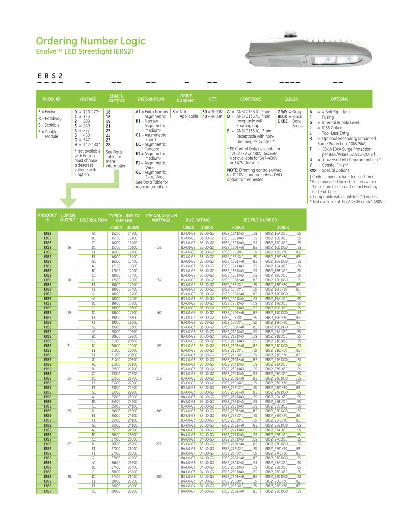
A1 = Extra Narrow Asymmetric B1 = Narrow Asymmetric (Medium)C1 = Asymmetric (Short)D1 = Asymmetric ForwardE1 = Asymmetric (Medium)F1 = Asymmetric (Wide)G1 = Asymmetric (Extra Wide)See Data Table for more information
E R S 2 _ _ _ _ _ _ _ _ _ _ _ _ _ _ _ _ _ _ _
PROD. ID VOLTAGELUMENOUTPUT
0 = 120-277*1 = 1202 = 2083 = 2404 = 2775 = 480D = 347H = 347-480** Not available with Fusing. Must choose a descreet voltage with F option.
30 = 3000K40 = 4000K
OPTIONSCOLORCONTROLS
A = 4 Bolt Slipfitter †F = FusingG = Internal Bubble LevelI = IP66 OpticalL = Tool-Less EntryR = Optional Secondary Enhanced Surge Protection (10kV/5kA)T = 20kV/10kA Surge Protection per IEEE/ANSI C62.41.2-2002 †U = Universal DALI Programmable +^Y = Coastal Finish*XXX = Special Options† Contact manufacturer for Lead-Time. * Recommended for installations within 1 mile from the coast. Contact Factory for Lead-Time.+ Compatible with LightGrid 2.0 nodes.^ Not available at 347V, 480V or 347-480V.
GRAY = GrayBLCK = BlackDKBZ = Dark Bronze
A = ANSI C136.41 7-pinD = ANSI C136.41 7-pin receptacle with Shorting CapE = ANSI C136.41 7-pin Receptacle with non- Dimming PE Control.*
* PE Control Only available for 120-277V or 480V Discrete. Not available for 347-480V or 347V Discrete.
NOTE: Dimming controls wired for 0-10V standard unless DALI option “U” requested.
CCTDISTRIBUTION
E = EvolveR = RoadwayS = Scalable2 = Double Module
Ordering Number LogicEvolve™ LED Streetlight (ERS2)
16181921232527 28
See Data Table for moreinformation.
DRIVECURRENT
X = Not Applicable
PRODUCTID
LUMENOUTPUT DISTRIBUTION
4000K 3000K
TYPICAL INITIAL LUMENS
TYPICAL SYSTEM WATTAGE
4000K4000K 3000K 3000K
IES FILE NUMBERBUG RATING
ERS2 A1 15200 14700 B3-U0-G3 B3-U0-G3 ERS2_16A1X40_____.IES ERS2_16A1X30_____.IES ERS2 B1 15700 15100 B3-U0-G2 B3-U0-G2 ERS2_16B1X40_____.IES ERS2_16B1X30_____.IES ERS2 C1 16000 15400 B3-U0-G2 B3-U0-G2 ERS2_16C1X40_____.IES ERS2_16C1X30_____.IES ERS2 16 D1 15700 15100 132 B3-U0-G2 B3-U0-G2 ERS2_16D1X40_____.IES ERS2_16D1X30_____.IES ERS2 E1 16000 15400 B3-U0-G2 B3-U0-G2 ERS2_16E1X40_____.IES ERS2_16E1X30_____.IES ERS2 F1 16000 15400 B3-U0-G2 B3-U0-G2 ERS2_16F1X40_____.IES ERS2_16F1X30_____.IES ERS2 G1 16000 15400 B3-U0-G2 B3-U0-G2 ERS2_16G1X40_____.IES ERS2_16G1X30_____.IES ERS2 A1 17100 16500 B3-U0-G3 B3-U0-G3 ERS2_18A1X40_____.IES ERS2_18A1X30_____.IES ERS2 B1 17600 17000 B3-U0-G2 B3-U0-G2 ERS2_18B1X40_____.IES ERS2_18B1X30_____.IES ERS2 C1 18000 17400 B3-U0-G2 B3-U0-G2 ERS2_18C1X40_____.IES ERS2_18C1X30_____.IES ERS2 18 D1 17600 17000 157 B3-U0-G2 B3-U0-G2 ERS2_18D1X40_____.IES ERS2_18D1X30_____.IES ERS2 E1 18000 17400 B3-U0-G2 B3-U0-G2 ERS2_18E1X40_____.IES ERS2_18E1X30_____.IES ERS2 F1 18000 17400 B3-U0-G3 B3-U0-G2 ERS2_18F1X40_____.IES ERS2_18F1X30_____.IES ERS2 G1 18000 17400 B3-U0-G2 B3-U0-G2 ERS2_18G1X40_____.IES ERS2_18G1X30_____.IES ERS2 A1 18000 17400 B3-U0-G3 B3-U0-G3 ERS2_19A1X40_____.IES ERS2_19A1X30_____.IES ERS2 B1 18600 17900 B3-U0-G2 B3-U0-G2 ERS2_19B1X40_____.IES ERS2_19B1X30_____.IES ERS2 C1 19000 18300 B3-U0-G2 B3-U0-G2 ERS2_19C1X40_____.IES ERS2_19C1X30_____.IES ERS2 19 D1 18600 17900 162 B3-U0-G2 B3-U0-G2 ERS2_19D1X40_____.IES ERS2_19D1X30_____.IES ERS2 E1 19000 18300 B3-U0-G2 B3-U0-G2 ERS2_19E1X40_____.IES ERS2_19E1X30_____.IES ERS2 F1 19000 18300 B3-U0-G3 B3-U0-G3 ERS2_19F1X40_____.IES ERS2_19F1X30_____.IES ERS2 G1 19000 18300 B3-U0-G3 B3-U0-G2 ERS2_19G1X40_____.IES ERS2_19G1X30_____.IES ERS2 A1 20000 19300 B3-U0-G3 B3-U0-G3 ERS2_21A1X40_____.IES ERS2_21A1X30_____.IES ERS2 B1 20600 19900 B3-U0-G2 B3-U0-G2 ERS2_21B1X40_____.IES ERS2_21B1X30_____.IES ERS2 C1 21000 20300 B3-U0-G2 B3-U0-G2 ERS2_21C1X40_____.IES ERS2_21C1X30_____.IES ERS2 21 D1 20600 19900 193 B3-U0-G2 B3-U0-G2 ERS2_21D1X40_____.IES ERS2_21D1X30_____.IES ERS2 E1 21000 20300 B3-U0-G2 B3-U0-G2 ERS2_21E1X40_____.IES ERS2_21E1X30_____.IES ERS2 F1 21000 20300 B3-U0-G3 B3-U0-G3 ERS2_21F1X40_____.IES ERS2_21F1X30_____.IES ERS2 G1 21000 20300 B3-U0-G3 B3-U0-G3 ERS2_21G1X40_____.IES ERS2_21G1X30_____.IES ERS2 A1 21900 21100 B4-U0-G3 B3-U0-G3 ERS2_23A1X40_____.IES ERS2_23A1X30_____.IES ERS2 B1 22500 21700 B3-U0-G3 B3-U0-G2 ERS2_23B1X40_____.IES ERS2_23B1X30_____.IES ERS2 C1 23000 22200 B3-U0-G2 B3-U0-G2 ERS2_23C1X40_____.IES ERS2_23C1X30_____.IES ERS2 23 D1 22500 21700 219 B3-U0-G2 B3-U0-G2 ERS2_23D1X40_____.IES ERS2_23D1X30_____.IES ERS2 E1 23000 22200 B3-U0-G2 B3-U0-G2 ERS2_23E1X40_____.IES ERS2_23E1X30_____.IES ERS2 F1 23000 22200 B3-U0-G3 B3-U0-G3 ERS2_23F1X40_____.IES ERS2_23F1X30_____.IES ERS2 G1 23000 22200 B3-U0-G3 B3-U0-G3 ERS2_23G1X40_____.IES ERS2_23G1X30_____.IES ERS2 A1 23800 23000 B4-U0-G3 B4-U0-G3 ERS2_25A1X40_____.IES ERS2_25A1X30_____.IES ERS2 B1 24500 23600 B4-U0-G3 B3-U0-G3 ERS2_25B1X40_____.IES ERS2_25B1X30_____.IES ERS2 C1 25000 24100 B3-U0-G2 B3-U0-G2 ERS2_25C1X40_____.IES ERS2_25C1X30_____.IES ERS2 25 D1 24500 23600 243 B3-U0-G3 B3-U0-G3 ERS2_25D1X40_____.IES ERS2_25D1X30_____.IES ERS2 E1 25000 24100 B3-U0-G3 B3-U0-G3 ERS2_25E1X40_____.IES ERS2_25E1X30_____.IES ERS2 F1 25000 24100 B3-U0-G3 B3-U0-G3 ERS2_25F1X40_____.IES ERS2_25F1X30_____.IES ERS2 G1 25000 24100 B3-U0-G3 B3-U0-G3 ERS2_25G1X40_____.IES ERS2_25G1X30_____.IES ERS2 A1 25700 24800 B4-U0-G3 B4-U0-G3 ERS2_27A1X40_____.IES ERS2_27A1X30_____.IES ERS2 B1 26500 25600 B4-U0-G3 B4-U0-G3 ERS2_27B1X40_____.IES ERS2_27B1X30_____.IES ERS2 C1 27000 26000 B4-U0-G3 B4-U0-G3 ERS2_27C1X40_____.IES ERS2_27C1X30_____.IES ERS2 27 D1 26500 25600 275 B3-U0-G3 B3-U0-G3 ERS2_27D1X40_____.IES ERS2_27D1X30_____.IES ERS2 E1 27000 26000 B4-U0-G3 B4-U0-G3 ERS2_27E1X40_____.IES ERS2_27E1X30_____.IES ERS2 F1 27000 26000 B4-U0-G4 B4-U0-G3 ERS2_27F1X40_____.IES ERS2_27F1X30_____.IES ERS2 G1 27000 26000 B4-U0-G3 B4-U0-G3 ERS2_27G1X40_____.IES ERS2_27G1X30_____.IES ERS2 A1 26600 25600 B4-U0-G3 B4-U0-G3 ERS2_28A1X40_____.IES ERS2_28A1X30_____.IES ERS2 B1 27400 26400 B4-U0-G3 B4-U0-G3 ERS2_28B1X40_____.IES ERS2_28B1X30_____.IES ERS2 C1 28000 26900 B4-U0-G3 B4-U0-G3 ERS2_28C1X40_____.IES ERS2_28C1X30_____.IES ERS2 28 D1 27400 26400 280 B3-U0-G3 B3-U0-G3 ERS2_28D1X40_____.IES ERS2_28D1X30_____.IES ERS2 E1 28000 26900 B4-U0-G3 B4-U0-G3 ERS2_28E1X40_____.IES ERS2_28E1X30_____.IES ERS2 F1 28000 26900 B4-U0-G4 B4-U0-G3 ERS2_28F1X40_____.IES ERS2_28F1X30_____.IES ERS2 G1 28000 26900 B4-U0-G4 B4-U0-G3 ERS2_28G1X40_____.IES ERS2_28G1X30_____.IES

PhotometricsEvolve™ LED Streetlight (ERS2)
Coe
ffici
ents
of U
tiliz
atio
n
Coe
ffici
ents
of U
tiliz
atio
n
ERS2Extra Narrow Asymmetric(27A1)
25,700 Lumens4000K ERS2_27A1X40____.IES
ERS2Narrow Asymmetric (Medium)(27B1)
26,500 Lumens4000K ERS2_27B1X40____.IES
Grid Distance in Units of Mounting Height at 30’ Initial Footcandle Values at Grade
Grid Distance in Units of Mounting Height at 30’ Initial Footcandle Values at Grade
Vertical plane through horizontal angle of maximum candlepower at 85°
Vertical plane through horizontal angle of 71°
Vertical plane through horizontal angle of maximum candlepower at 85°
Vertical plane through horizontal angle of 71°
SSHS
SSHS
1.0
0.9
0.8
0.7
0.6
0.5
0.4
0.3
0.2
0.1
0.0 0 1 2 3 4 5
SS
HS
1.0
0.9
0.8
0.7
0.6
0.5
0.4
0.3
0.2
0.1
0.0 0 1 2 3 4 5
SS
HS
Street Width/Mounting Height
Street Width/Mounting Height
.1.2.5
Coe
ffici
ents
of U
tiliz
atio
n
Coe
ffici
ents
of U
tiliz
atio
n
Grid Distance in Units of Mounting Height at 30’ Initial Footcandle Values at Grade
Grid Distance in Units of Mounting Height at 30’ Initial Footcandle Values at Grade
ERS2Asymmetric Short(27C1)
27,000 Lumens4000K ERS2_27C1X40____.IES
ERS2Asymmetric Forward(27D1)
26,500 Lumens4000K ERS2_27D1X40____.IES
SS
SS
HS
HS
1.0
0.9
0.8
0.7
0.6
0.5
0.4
0.3
0.2
0.1
0.0
1.0
0.9
0.8
0.7
0.6
0.5
0.4
0.3
0.2
0.1
0.0
0 1 2 3 4 5
0 1 2 3 4 5
SS
SS
HS
HS
Vertical plane through horizontal angle of maximum candlepower at 0°
Vertical plane through horizontal angle of 38°
Vertical plane through horizontal angle of maximum candlepower at 5°
Vertical plane through horizontal angle of 41°
Street Width/Mounting Height
Street Width/Mounting Height
.1.2
15171
11379
7586
3793
1
1
21621
16216
10810
5405
1
2
15606
11705
7803
3902
1
2
.5
.1.2
15282
11462
7641
3821
2
.1
.2.5
2.5
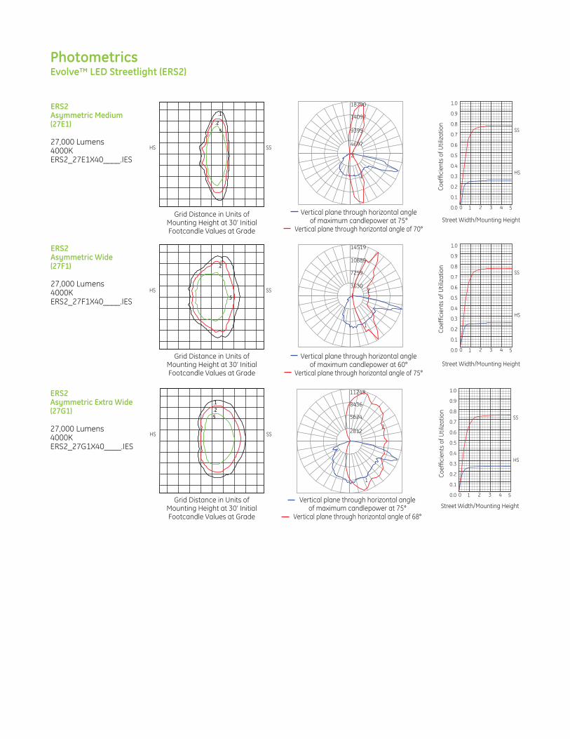
PhotometricsEvolve™ LED Streetlight (ERS2)
Coe
ffici
ents
of U
tiliz
atio
n
Coe
ffici
ents
of U
tiliz
atio
n
ERS2Asymmetric Medium(27E1)
27,000 Lumens4000K ERS2_27E1X40____.IES
ERS2Asymmetric Wide(27F1)
27,000 Lumens4000K ERS2_27F1X40____.IES
Grid Distance in Units of Mounting Height at 30’ Initial Footcandle Values at Grade
Grid Distance in Units of Mounting Height at 30’ Initial Footcandle Values at Grade
Vertical plane through horizontal angle of maximum candlepower at 75°
Vertical plane through horizontal angle of 70°
Vertical plane through horizontal angle of maximum candlepower at 60°
Vertical plane through horizontal angle of 75°
SSHS
SSHS
1.0
0.9
0.8
0.7
0.6
0.5
0.4
0.3
0.2
0.1
0.0 0 1 2 3 4 5
SS
HS
1.0
0.9
0.8
0.7
0.6
0.5
0.4
0.3
0.2
0.1
0.0 0 1 2 3 4 5
SS
HS
Street Width/Mounting Height
Street Width/Mounting Height
1
2
.5
.1.2
Coe
ffici
ents
of U
tiliz
atio
n
Grid Distance in Units of Mounting Height at 30’ Initial Footcandle Values at Grade
ERS2Asymmetric Extra Wide(27G1)
27,000 Lumens4000K ERS2_27G1X40____.IES
SSHS
1.0
0.9
0.8
0.7
0.6
0.5
0.4
0.3
0.2
0.1
0.0 0 1 2 3 4 5
SS
HS
Vertical plane through horizontal angle of maximum candlepower at 75°
Vertical plane through horizontal angle of 68°
Street Width/Mounting Height
.1
.2.5
11248
8436
5624
2812
1
2
18790
14092
4697
9395
.1
.2.5
14519
10889
7259
3630
1
2

Product Dimensions Evolve™ LED Streetlight (ERL1)
ADJUSTABLE FOR 1-1/4 to 2 inch PIPE (1.660 to 2.375 inch OD)
[42 to 60 mm OD]
22.1 in.[561 mm]
13.5 in.[344 mm]
14.7 in. R[373 mm R]
5.4 in.[137 mm]
9.6 in.[243 mm]
Optional LightGrid Node
6.4 in.[162 mm]4.2 in.
[107 mm]
14.2 in.[360 mm]
SIDE VIEWBACK VIEW FRONT VIEW
• Approximate net weight: 12.4 lbs (5.6 kgs) - Without XFMR • Approximate net weight: 15.5 lbs (7 kgs) - With XFMR• Effective Projected Area (EPA): 0.5 sq ft max (0.046 sq m)D
ATA

ADJUSTABLE FOR 1-1/4 to 2 inch PIPE (1.660 to 2.375 inch OD)[42 to 60 mm OD]
22.1 in.[561 mm]
13.5 in.[344 mm]
14.7 in. R[373 mm R]
9.6 in.[243 mm]
5.4 in.[137 mm]
Optional LightGrid
Node
6.4 in.[162 mm]4.2 in.
[107 mm]
14.2 in.[360 mm]
Product Dimensions Evolve™ LED Streetlight (ERLH)
SIDE VIEW
• Approximate net weight: 15.15 lbs (6.9 kgs) - 2 Bolt Slipfitter • Approximate net weight: 15.85 lbs (7.2 kgs) - 4 Bolt Slipfitter• Effective Projected Area (EPA): 0.5 sq ft max (0.046 sq m)D
ATA
BACK VIEW FRONT VIEW

Product Dimensions
SIDE VIEW
BACK VIEW
FRONT VIEW
Evolve™ LED Streetlight (ERS1)
7.0 in.[177mm] 5.4 in.
[136 mm]
14.5 in.[368 mm]
21.3 in.[542 mm]
11.8 in. R[300 mm R]
4.5 in.[114 mm]
Adjustable for 1-1/4 to 2 in. mounting pipe(1.660 to 2.375 inch OD)[42 to 60 mm OD]
21.3 in.[542 mm]
14.5 in.[368 mm]
9.9 in.[251.46 mm]
Optional LightGrid Node
• Approximate net weight: 20 lbs (9.1 kgs) to 25 lbs (11.4 kgs)
• Effective Projected Area (EPA): 0.5 sq ft max (0.046 sq m)DA
TA

www.gelighting.comGE and the GE Monogram are trademarks of the General Electric Company. All other trademarks are the property of their respective owners. Information provided is subject to change without notice. All values are design or typical values when measured under laboratory conditions. GE Lighting is a business of the General Electric Company. © 2016 GE.
OLP3105 (Rev 04/19/16)
Evolve™ LED Streetlight (ERS2)
• Approximate net weight: 25 lbs (11.4 kgs) to 29 lbs (13.2 kgs)
• Effective Projected Area (EPA): 0.7 sq ft max (0.065 sq m)DA
TA
Product Dimensions
SIDE VIEW
BACK VIEW
FRONT VIEW
14.5 in.[368 mm]
7.0 in.[177mm]
14.5 in.[368 mm]
25.9 in.[659 mm]
11.8 in. R[300 mm R]
4.5 in.[114 mm]
Adjustable for 1-1/4 to 2 in. mounting pipe(1.660 to 2.375 inch OD)[42 to 60 mm OD]
5.4 in.[136 mm]
25.9 in.[659 mm]
Optional LightGrid Node
9.9 in.[251.46 mm]

A V I S T AL E D L i g h t E n g i n eU.8.5.15
www.amerluxexterior.com • 5220 Shank Rd. Pearland, Texas 77581 • (T) 281.997.5400 • (F)281-997-5441
CONSTRUCTION:• Anodized Aluminum Heat Sink• IP66 Rated• Cast aluminum fitter plate provided• Sealed LED chamber and optics
INSTALLATION:Height adjustable light engine can be field adjusted to optimal performance. LED retrofit kit mounts to many existing luminaires.
ELECTRICAL:• Automatic AC incoming voltage sensing 120–277• Over voltage and short circuit protection• 10kv surge protector
APPLICATION:LED Light engine for use in post top mount area and pedestrian environments. Designed for new fixtures or existing as a retrofit.
EFFICACY:Up to 100 lumens/ watt
LIFE:50,000+ hours
DISTRIBUTION:SY - SymmetricAS - AsymmetricSO - Street Optic
NOMINAL INPUT POWER:41W, 60W
CCT:3000K, 4000K, 5000K
AVILED
TYPE:
PROJECT:
Example: AVI / SY / 3H
Part String
Electrostatic sensitive device.observe precautions for handling
6.5"
8" to 12"
Ø6.85"
2.5"
AVI / SY/ XXAVI / SO/ XX
3.65"
2.86"
AVI / AS / XX
12" to 16"
2.5"
AVI -T/ SY / XX
Model
AVIAVI-T
Code
3H4H5H3H4H5H3H4H5H3L4L5L3L4L5L3L4L5L
CCT
3,000K4,000K5,000K3,000K4,000K5,000K3,000K4,000K5,000K3,000K4,000K5,000K3,000K4,000K5,000K3,000K4,000K5,000K
Light Distribution
SY(Symmetric)
AS(Asymmetric)
AS
SY
Nominal InputPower
60W
41W
CRI
808080808080808080808080808080808080
Approx. Lumens Delivered
4,450 lm5,100 lm5,870 lm4,410 lm5,050 lm5,810 lm4,340 lm4,990 lm5,760 lm2,940 lm3,460 lm4,070 lm2,910 lm3,420 lm4,030 lm2,830 lm3,350 lm3,960 lm
Ordering Information
SO(Street Optic)
SO

P R O J E C T :
T Y P E :
Model CCT
40 (4000K)
Code
4H
4L N/A
60
41
AVI SY - symmetricAS - asymmetric
AccessoriesWattsLight Distribution
QUICKSHIP ORDERING INFORMATION:
• QuickShip must be clearly marked on all P.O’s.• Standard shipping terms apply. • See terms & conditions below.
Amerlux® QuickShip makes it possible not only to keep up with expectations, butto keep ahead of them. We help enhance your competitive edge, ensuring youcan start installation more quickly than you thought possible.
We can ship within 5-10 business days of your Amerlux QuickShip order, dependingupon the selection.
Quantity: 50 pieces or less 5 days
Cat #:
Complete QuickShip Example: AVI-SY-4H
1. For QuickShip processing, please submit QuickShip items on separate purchase order and indicate “QuickShip” on order. 2. Con�gurations outside of what is displayed on the QuickShip program are not available under the QuickShip lead times. 3. Please contact Customer Support to process orders with quantities larger than those listed.
4. Orders will be entered within 24 hours of receipt of a clean purchase order. Lead times are calculated by business days from time of sales order con�rmation. Orders will ship within QuickShip lead times or sooner.
5. Change orders and order cancellations cannot be processed after sales order con�rmation is generated.
6. For freight allowed (greater than $3,000), order will ship complete based on longest lead time item. Please indicate on PO if Partial Shipments are approved and indicate freight method. For partial shipments under $3,000, customer will be invoiced for freight.
7. All Lead times indicate when the �xture ships from Amerlux®. Arrival at destination is contingent upon carrier.
Expedite your orders by providing: - Separate purchase order noting “QuickShip Program” - Complete and accurate con�gurations - Accurate pricing, quote number, shipping and contact information
Amerlux reserves the right to modify this program at any time.
Terms & Conditions
AVILED
Amerlux®, LLC • 178 Bauer Dr, Oakland, NJ 07436 • P: 973.882.5010 F: 973-882.2605 • www.amerlux.com
Q U I C K S H I P AVISTA®
L E D L I G H T E N G I N E

www.amerluxexterior.com • 5220 Shank Rd. Pearland, Texas 77581 • (T) 281.997.5400 • (F)281-997-5441
Photometry
Mounting Plate
Ø6.50
Ø5.62 bolt circleDesigned for usewith 1/4 20 screws
15° x 2
A V I S T AL E D L i g h t E n g i n eU.6.11.15
522
1044
1565
2087
Maximum Candela = 2087.006 Located At Horizontal Angle = 5, Vertical Angle = 62.5# 1 - Vertical Plane Through Horizontal Angles (5 -185) # 2 - Horizontal Cone Through Vertical Angle (62.5)
1
2
AS POLAR GRAPHSY POLAR GRAPH
295
591
886
1181
2
Maximum Candela=1181 Located At Horizontal Angle=0, Vertical Angle=60 # 1 - Vertical Plane Through Horizontal Angles (0 - 180) # 2 - Horizontal Cone Through Vertical Angle (60)
1
1209
2419
3628
4837
1
2
Maximum Candela = 4837Located At Horizontal Angle = 70, Vertical Angle = 62.5# 1 - Vertical Plane Through Horizontal Angles (70 - 250)# 2 - Horizontal Cone Through Vertical Angle (62.5)
SO POLAR GRAPH

Roadway Lighting ATBM Note: Specifications subject to change without notice.
P R O D U C T O V E R V I E W
Applications:Residential streetsParking lotsHigh speed roadways
Autobahn Series ATBM Roadway
Features:OPTICALSame Light: Performance is comparable to 150W – 250W HPS
White Light: Correlated color temperature - standard 4000K, 70 CRI minimum or optional 5000K, 70 CRI minimum. IP66 rated borosilicate glass optics ensure longevity and minimize dirt depre-ciation. Unique IP66 rated LED light engines provide 0% uplight and restrict backlight to within sidewalk depth, providing optimal application coverage and optimal pole spacing.
Available distributions are Type II, III, IV, & V roadway distributions.
ELECTRICALExpected Life: LED light engines are rated >100,000 hours at 25°C, L70. Electronic driver has an expected life of 100,000 hours at a 25°C ambient.
Lower Energy: Saves an expected 40-60% over comparable HID luminaires.
Robust Surge Protection: Three different surge protection options provide a minimum of IEEE/ANSI C62.41 Category C (10kV/5kA) protection. MECHANICALIncludes standard AEL lineman-friendly features such as tool-less entry, 3 station terminal block and quick disconnects. Bubble level located inside the electrical compartment for easy leveling at installation. Rugged die-cast aluminum housing and door are polyester powder-coated for durability and corrosion resistance. Rigorous five-stage pre-treating and painting process yields a finish that achieves a scribe creepage rating of 8 (per ASTM D1654) after over 5000 hours exposure to salt fog chamber (oper-ated per ASTM B117). Mast arm mount is adjustable for arms from 1-1/4” to 2” (1-5/8” to 2-3/8” O.D.) diameter. The 2 – bolt and optional 4 bolt clamping mechanism provide 3G vibration rating per ANSI C136.
The Wildlife shield is cast into the housing (not a separate piece). CONTROLSNEMA 3 pin photocontrol receptacle is standard, with the Acuity designed ANSI standard 5 pin and 7 pin receptacles optionally available. Premium solid state locking-style photocontrol – PCSS (10 year rated life) Extreme long life solid state locking-style photocontrol – PCL1 (20 year rated life).
Extreme long life solid state locking-style photocontrol with on demand remote on/off control - PCCC (15 year rated life).
Optional onboard Adjustable Output module allows the light output and input wattage to be modified to meet site specific requirements, and also can allow a single fixture to be flexibly applied in many different applications. STANDARDSDesignLights Consortium® (DLC) qualified product. Not all versions of thisproduct may be DLC qualified. Please check the DLC Qualified Products List at www.designlights.org/QPL to confirm which versions are qualified.Rated for -40°C to 40°C ambientCSA Certified to U.S. and Canadian standardsComplies with ANSI: C136.2, C136.10, C136.14, C136.31, C136.15, C136.37
DIMENSIONS
Effective Projected Area (EPA)The EPA for the ATBM is 0.3 sq. ft.,Approx. Wt. = 21 lbs. (9.5 kg)
DIMENSIONS
23.75”
7.5”
4.5”
11”
Drop Refractor
1.44 in
13"
4-1/2"
28"

Warranty Five-year limited warranty. Complete warranty terms located at: www.acuitybrands.com/CustomerResources/Terms_and_conditions.aspx Actual performance may differ as a result of end-user environment and application. Specifications subject to change without notice.
Please contact your sales representative for the latest product information.
AEL Headquarters, 3825 Columbus Road, Granville, OH 43023www.americanelectriclighting.com© 2014-2016 Acuity Brands Lighting, Inc. All Rights Reserved. 02/18/16
ATBM
Example: ATBM A MVOLT R2
ATBM Autobahn LED Roadway
MVOLT Multi-volt, 120-277V
347 347V 480 480V
A 7,000 lumensB 8,000 lumensC 9,000 lumensD 11,600 lumensE 13,400 lumensF 15,700 lumensG 16,600 lumensH 17,400 lumens
Color Temperature (CCT) (Blank) 4000K CCT, 70 CRI Min. 5K 5000K CCT, 70 CRI Min.
Paint (Blank) Gray BK Black BZ Bronze DDB Dark Bronze GI Graphite WH White
Surge Protection (Blank) Acuity SPD MP MOV Pack1
IL SPD with Indicator Light1
Miscellaneous Options HSS House Side Shield NL NEMA Label Indicating Wattage XL Not CSA Certified – No Terminal Block Cover
Options
Control Options (Blank) 3 Pin NEMA Photocontrol Receptacle P5 5 Pin Photocontrol Receptacle (dimmable driver included)2
P7 7 Pin Photocontrol Receptacle (dimmable driver included)2
NR No Photocontrol Receptacle3
AO Field Adjustable Output DM 0-10V Dimmable Driver PCSS Solid-State Lighting Photocontrol PCLL Solid-State Long Life Photocontrol PCCC Solid-State Long Life Photocontrol with remote control on/off SH Shorting Cap
Packages (Blank) Standard Pack JP Job Pack (36/pallet)
(Blank) 2 Bolt Mounting 4B 4 Bolt Mounting
MountingVoltagePerformance PackagesSeries
Autobahn Series ATBM Roadway
O R D E R I N G I N F O R M A T I O N
Accessories ATBMHSS House Side Shield ATBMLTS Light Trespass
Shield RKATBMMVOLTSPD ATBM Acuity SPD
Replacement Kit MVOLT
RKATBMHVSPD ATBM Acuity SPD Replacement Kit 347/480V
RKATBMMVOLTMP ATBM MOV Pack Replacement Kit
RKATBMMVOLTIL ATBM IL SPD Replaement Kit
R2 Roadway Type IIR3 Roadway Type IIIR4 Roadway Type IVR5 Roadway Type V
Optics
Notes:1 Not available with G and H performance packages2 Dimmable Driver included. Not available with AO, DM or NR3 Not available with P5, P7, 347 or 480 Volt4 Not available with DM, P5 or P75 Controls by others. Not available with AO6 MVOLT only7 Not available with PCSS or PCLL

Warranty Five-year limited warranty. Complete warranty terms located at: www.acuitybrands.com/CustomerResources/Terms_and_conditions.aspx Actual performance may differ as a result of end-user environment and application. Specifications subject to change without notice.
Please contact your sales representative for the latest product information.
AEL Headquarters, 3825 Columbus Road, Granville, OH 43023www.americanelectriclighting.com© 2014-2016 Acuity Brands Lighting, Inc. All Rights Reserved. 02/18/16
ATBM
P E R F O R M A N C E P A C K A G E
Autobahn Series ATBM Roadway
Performance Package Distribution
4000 K CCT LLD @ 25°C
Lumens Input Watts LPW 50K Hours 75K Hours 100K Hours
A
R2 7,114
60
118
89 84 80R3 7,024 117R4 6,958 116R5 7,469 124
B
R2 8,090
70
115
89 84 80R3 8,016 114R4 7,924 113R5 8528 121
C
R2 9031
81
112
89 84 80R3 8,942 111R4 8,827 110R5 9,517 118
D
R2 11,769
95
124
90 87 84R3 11,690 123R4 11,534 121R5 12,388 130
E
R2 13,601
115
118
90 87 84R3 13,416 117R4 13,323 116R5 14,263 124
F
R2 15,932
133
120
90 86 83R3 15,741 118R4 15,476 116R5 16,691 125
G
R2 17,102
150
114
90 86 83R3 16,974 113R4 16,635 111R5 17,938 119
H
R2 18,085
164
111
90 86 83R3 17,929 110R4 17,439 107R5 18,966 116

P R O D U C T O V E R V I E W
Applications:Residential streetsParking lotsGeneral security lighting
Autobahn Series ATBS Roadway & Security Lighting
DIMENSIONS
Features:OPTICAL
Same Light: Performance is comparable to 50W – 150W HPS and up to 175W Mercury Vapor roadway and security lighting luminaires.
White Light: Correlated color temperature - standard 4000K, 70 CRI minimum or optional 5000K, 70 CRI minimum. IP66 rated borosilicate glass optics ensure longevity and minimize dirt depreciation. Unique IP66 rated LED light engines provide 0% uplight and restrict backlight to within sidewalk depth, providing optimal application coverage and optimal pole spacing.
Available distributions are Type II, III, and V roadway distributions. When used with the optional acrylic refractor the unit provides approximately 10% uplight and increased vertical foot-candles ELECTRICAL
Expected Life: LED light engines are rated >100,000 hours at 25°C, L70. Electronic driver has an expected life of 100,000 hours at a 25°C ambient.
Lower Energy: Saves an expected 40-60% over comparable HID luminaires.
Robust Surge Protection: Three different surge protection options provide a minimum of IEEE/ANSI C62.41 Category C (10kV/5kA) protection. MECHANICAL
Includes standard AEL lineman-friendly features such as tool-less entry, 3 station terminal block and quick disconnects. Bubble level located inside the electrical compartment for easy leveling at installation. Rugged die-cast aluminum housing and door are polyester powder-coated for durability and corrosion resistance. Rigorous five-stage pre-treating and painting process yields a finish that achieves a scribe creepage rating of 8 (per ASTM D1654) after over 5000 hours exposure to salt fog chamber (operated per ASTM B117). Mast arm mount is adjustable for arms from 1-1/4” to 2” (1-5/8” to 2-3/8” O.D.) diameter. The 2 – bolt clamping mechanism provides 3G vibration rating per ANSI C136.
The Wildlife shield is cast into the housing (not a separate piece). CONTROLS
NEMA 3 pin photocontrol receptacle is standard, with the Acuity designed ANSI standard 5 pin and 7 pin receptacles optionally available. Premium solid state locking-style photocontrol – PCSS (10 year rated life) Extreme long life solid state locking-style photocontrol – PCL1 (20 year rated life)
Optional onboard Adjustable Output module allows the light output and input wattage to be modified to meet site specific requirements, and also can allow a single fixture to be flexibly applied in many different applications. STANDARDS
Rated for -40°C to 40°C ambient CSA Certified to U.S. and Canadian standards Complies with ANSI: C136.2, C136.10, C136.14, C136.31, C136.15, C136.37
23.75”
7.5”
4.5”
11”
Drop Refractor
Effective Projected Area (EPA) The EPA for the ATBS is 0.3 sq. ft.,Approx. Wt. = 12 lbs. (5 kg)
Note: Specifications subject to change without notice. Actual performance may differ as a result of end-user environment and application.
© 2014-2016 Acuity Brands Lighting, Inc. 03/29/16

Warranty Five-year limited warranty. Complete warranty terms located at: www.acuitybrands.com/CustomerResources/Terms_and_conditions.aspx Actual performance may differ as a result of end-user environment and application. All values are design or typical values, measured under laboratory conditions at 25 °C. Specifications subject to change without notice.
Please contact your sales representative for the latest product information.
AEL Headquarters, 3825 Columbus Road, Granville, OH 43023www.americanelectriclighting.com© 2014-2016 Acuity Brands Lighting, Inc. All Rights Reserved. 03/29/16
Example: ATBS A MVOLT R2
ATBS Autobahn LED Roadway &
Security
MVOLT Multi-volt, 120-277VA 1,900 lumensB 2,600 lumensE 4,000 lumens F 4,800 lumens G 6,100 lumens H 7,100 lumensI 8,500 lumens
Color Temperature (CCT) (Blank) 4000K CCT, 70 CRI Min. (standard) 5K 5000K CCT, 70 CRI Min.
Paint Blank Gray (Standard) BK Black WH White BZ Bronze Surge ProtectionStandard 10kV/5kA SPD Blank Acuity SPD-10kV/5kA with inductive filter (Standard) MP MOV Pack IL SPD with Indicator Light Misc. HSS House Side Shield NL NEMA Label XL Not CSA Certified
Options
Controls (Blank) 3 Pin NEMA Photocontrol Receptacle NR1 No Photocontrol Receptacle DM2 0V-10V Dimmable Driver P5 5 Pin Photocontrol Receptacle (dimmable driver included) P7 7 Pin Photocontrol Receptacle (dimmable driver included) PCSS1 DTL DSS Photocontrol PCL11 DTL DLL Photocontrol 120-277V AO Field Adjustable Output SH Shorting Cap
Install Packages PKGS DTL DSS Photocontrol PKGL DTL DLL Photocontrol Packages ship with selected photocontrol, 24”, 1 1/4” diameter arm, 5’ of prewire and mounting hardware
R2 Roadway Type IIR3 Roadway Type IIIR5 Roadway Type VD2 Type II, Drop Refractor
included D3 Type III, Drop Refractor
included D5 Type V, Drop Refractor
included
OpticsVoltagePerformance Packages Series
Autobahn Series ATBS Roadway & Security Lighting
O R D E R I N G I N F O R M A T I O N
Notes 1. Not available with Install Packages.2. Not available with AO option.
Accessories ATBSREF Drop Refractor for field installation ATBSHSS House Side Shield for field installation ATBSLTS Light Trespass Shield for field installation

Warranty Five-year limited warranty. Complete warranty terms located at: www.acuitybrands.com/CustomerResources/Terms_and_conditions.aspx Actual performance may differ as a result of end-user environment and application. All values are design or typical values, measured under laboratory conditions at 25 °C. Specifications subject to change without notice.
Please contact your sales representative for the latest product information.
AEL Headquarters, 3825 Columbus Road, Granville, OH 43023www.americanelectriclighting.com© 2014-2016 Acuity Brands Lighting, Inc. All Rights Reserved. 03/29/16
P E R F O R M A N C E P A C K A G E
Autobahn Series ATBS Roadway & Security Lighting
Performance Package Distribution Lumens Input Watts LPW 50K Hours LLD @ 25°C
75K Hours 100K Hours
A
R2 1,978
19
104
0.93 0.89 0.85
R3 1,972 104R5 2,033 107D2 1,884 99D3 1,860 98D5 1,933 102
B
R2 2,611
27
97
0.93 0.89 0.85
R3 2,603 96R5 2,694 100D2 2,487 92D3 2,456 91D5 2,564 95
E
R2 4,196
40
105
0.93 0.89 0.85
R3 3,977 99R5 4,282 107D2 3,996 100D3 3,752 94D5 4,091 102
F
R2 4,661
47
99
0.93 0.8 0.8
R3 4,821 103R5 4,666 99D2 4,439 94D3 4,548 97D5 4,554 97
G
R2 6,235
50
125
0.94 0.92 0.90
R3 6,101 122R5 6,404 128D2 5,938 119D3 5,756 115D5 6,193 124
H
R2 7194
60
120
0.94 0.92 0.90
R3 7,141 119R5 7,508 125D2 6,851 114D3 6,737 112D5 7, 131
I
R2 8,653
76
114
0.94 0.92 0.90
R3 8,525 112R5 9,003 118D2 8,241 108D3 8,042 106D5 124
Note: Information shown above is based on nominal system data. Individual fixture performance may vary. Specifications subject to change without notice.

NFFLD NIGHT FALCON
Solid State LED
FLOODLIGHT
LUMARK®
SPECIFICATION FEATURES
ConstructionHeavy-duty, die cast aluminum housing, driver compartment and driver housing door. A separate driver compartment and external fins provide optimal thermal management that result in longer LED and driver life.The housing, driver compartment and optical chamber are IP66 rated. Access to the driver for maintenance is achieved with a removable driver door using pan head screws. A one-piece silicone gasket seals the door to the fixture housing. The fixture is 3G vibration rated (ANSI C136.31) to ensure durability in area and site lighting applications.
OpticsThe LED chamber incorporates a vacuum metalized reflector that provides high-efficiency illumination. Optics are precisely designed to shape the wide NEMA type 6H x 6V distribution, maximizing efficiency and application spacing. Clear glass tempered lens with full circumference form-in-place silicone gasket protects the optics from damage. Offered standard in 4000K (+/- 275K) CCT and minimum 70 CRI. Optional 5700K CCT and 3000K CCT and minimum 70 CRI are available.
ElectricalLED driver is mounted to the removable die-cast aluminum door for optimal heat sinking and ease of maintenance. 120-277V 50/60Hz, 347V 60Hz or 480V 60Hz operation. Integral 6kV surge is standard.10kV/10kA common- and differential- mode surge protection available as an option. 0-10V dimming driver is available to accommodate controls capability such as dimming and occupancy. Standard NEMA 3-PIN twistlock photocontrol receptacle and NEMA 7-PIN twistlock photocontrol receptacles are available as options. Suitable for ambient temperatures from -40°C to 40°C. Optional 50°C HA (high ambient) available. 90% lumen maintenance greater than 50,000 hours per IESNA TM-21.
AccessoriesHeavy-duty steel top and side visors control glare and spill light. 1/8” thick UV stabilized vandal guard shields glass lens from impact when mounted at low levels. Easy to install wire guard features a heavy-gauge welded construction with corrosion resistant polyester powder coat finish to protect glass from projected objects.
MountingMounting options include an integral die-cast aluminum slipfitter that is preset to a tilt of 45°. The knuckle base is supplied with a tooth lock adjustment that can be adjusted in 5° increments to provide flexibility in aiming the fixture from a variety of surfaces. Visual 15° adjustment indicators on the knuckle allow for 180° field rotation of the floodlight assembly. The slipfitter fits standard 2-3/8”-3” O.D. tenon. The trunnion mounting includes a 3/16” polyester powder coated galvanized steel trunnion with a 16/3 SOW cord. The trunnion mount uses an interlocking slide adjustment that is locked into place with a set screw.
FinishHousing and cast parts finished in five-stage super TGIC polyester powder coat paint, 2.5 mil nominal thickness for superior protection against fade and wear. Standard color is carbon bronze. Additional colors available in summit white, grey and black. Consult your Eaton’s Cooper Lighting business representative for a complete selection of standard colors.
WarrantyFive-year warranty.
ADH1424372015-01-09 12:24:10
The Night Falcon™ LED floodlight luminaire combines high-efficiency optics, superior thermal management and energy efficiency in a cost-effective solution. The compact, robust design incorporates a separate driver compartment for maximum heat dissipation to insure longevity of both the fixture and the LEDs. The Night Falcon luminaire uses precision engineered optics delivering superior uniformity and excellent illumination to the targeted application. Typical applications include area lighting for security, building facade lighting, accent and signage lighting in both commercial and industrial applications. The Night Falcon luminaire is UL/cUL listed for wet locations and is IP66 rated.
DESCRIPTION
C E R T I F I C A T I O N D A T AUL/cUL Wet Location Listed IP66 Fixture and Optical ChamberLM79/LM80 Compliant3G Vibration RatedRoHS CompliantDesignLights Consortium® Qualified*
E N E R G Y D A T AElectronic LED Driver> 0.9 Power Factor< 20% Total Harmonic Distortion120V 50/60Hz, 347V/60Hz and 480V/60Hz-40°C Minimum Ambient Temperature Rating+40°C Maximum Ambient Temperature Rating
E P AEffective Projected Area (Sq. Ft.): 1.25
S H I P P I N G D A T AApproximate Net Weight: 20 lbs. (9.09 kgs.)
S
YSTEMS
C
E RT I F I E
D
Slipfitter Mount
15-15/16"[405mm]
8-11/16"[221mm]
8-7/16"[215mm]
Trunnion Mount
15-15/16"[405mm]
15-5/16"[388mm]
12-11/16"[322mm]
8-11/16"[221mm]
8-7/16"[215mm]
DIMENSIONS
(2) 9/16"[14mm]
(2) 7/16"[11mm]
7/8" [22mm]9-1/8" [232mm]
3-3/4" [95mm]
2"[51mm]
2" [51mm]
TRUNNION MOUNT DRILL PATTERN
Catalog # Type
Date
Project
Comments
Prepared by
*www.designlights.org

Eaton1000 Eaton BoulevardCleveland, OH 44122United StatesEaton.com
Specifications and dimensions subject to change without notice.
Eaton’s Cooper Lighting Business 1121 Highway 74 SouthPeachtree City, GA 30269P: 770-486-4800www.cooperlighting.com
NFFLD NIGHT FALCON
ADH1424372015-01-09 12:24:10
Sample Number: NFFLD-A40-E-UNV-66-S-CB-PER
Product Family 1 Light Engine 2 Driver 3 Voltage Distribution Mounting Color
NFFLD= Night Falcon LED Floodlight
A25=9,400 Nominal LumensA40=14,600 Nominal Lumens
E=Non-DimmingD=Dimming (0-10V)
UNV= 120-277V347=347V 4
480=480V 4
66= NEMA 6H x6V Wide S= Slipfi tter 5
T=TrunnionCB= Carbon Bronze (Standard)BK= BlackAP= GreyWHT= Summit White
Options (Add as Suffi x) Accessories (Order Separately) 8
7030=70 CRI / 3000K 6
7060=70 CRI / 5700K 6
PER=NEMA 3-PIN Twistlock Photocontrol ReceptaclePER7=NEMA 7-PIN Twistlock Photocontrol Receptacle 7
10K=10kV/10kA UL 1449 Surge Protective DeviceHA=50°C High Ambient TemperatureD10=<10% Dimming 7
FA63=3" O.D. Surface Mount Bracket 9
OA1223=10kV/10kA UL 1449 Surge Protective Device ReplacementOA/RA1013=Photocontrol Shorting CapOA/RA1014=NEMA Photocontrol - 120VOA/RA1016=NEMA Photocontrol - Multi-TapOA/RA1027=NEMA Photocontrol - 480VOA/RA1201=NEMA Photocontrol - 347VRAB-XX=Right Angle Pipe Bracket for Slipfi tterSAB-XX=Steel Angle Bracket for TrunnionTYS-XX=Slipfi tter Adapter for 2-3/8", 3" or 3-1/2" O.D. Tenon 10
TS2/NFFLD-XX=Top and Side Visors 11
VS/NFFLD=Vandal Shield 11
WG/NFFLD=Wire Guard 11
NOTES: 1. DesignLights Consortium® Qualifi ed. Refer to www.designlights.org Qualifi ed Products List under Family Models for details. 2. Standard 4000K CCT and minimum 70 CRI. Consult IES fi le for actual lumen output.3. Consult factory for driver surge protection values.4. Not recommended for use with ungrounded, delta confi gured systems.5. Fits 2-3/8" to 3" O.D. tenon, wire leads run through slipfi tter.6. Extended lead times apply. Use dedicated IES fi les for 3000K and 5700K when performing layouts. These fi les are published on the Night Falcon luminaire product page on the website.7. Must order with dimming driver.8. Replace XX with color designation. Additional brackets and adaptors available on the poles product page on the website.9. Not available with tenon mount.10. Not available with slipfi tter mount.11. Cannot combine TS2 (Top and Side Visor), VS (Vandal Shield), or WG (Wire Guard), limited to one external guard per fi xture.
ORDERING INFORMATION
Stock Sample Number: NFFLD-A40-S
Series Light Engine Mounting Voltage
NFFLD=Night Falcon A25= 9,400 Nominal LumensA40= 14,600 Nominal Lumens
S= Slipfi tterT=Trunnion
[BLANK]=120-277V347=347V
NOTES: Options not available with stock products. Order accessories as separate items for fi eld installation. Refer to standard ordering information to add options. Refer to In-Stock Guide for availability. Stock fi xture is 4000K, non-dimming, 120-277V or 347V, carbon bronze only.
STOCK ORDERING INFORMATION
8-1/2"[215mm]
15-15/16"[405mm]
15-7/8"[404mm]
17"[432mm]3"
[77mm]
9-1/2"[241mm]
1-1/16"[27mm]
1-1/16"[27mm]
8-3/4"[222mm]
Top and Side Visors Wire Guard Vandal Shield
ACCESSORIES
AmbientTemperature
TM-21 Lumen Maintenance
(50,000 Hours)
Theoretical L70 (Hours)
NFFLD-A25
25°C > 93% > 300,000
40°C > 93% > 295,000
50°C > 92% > 285,000
NFFLD-A40
25°C > 93% > 290,000
40°C > 92% > 285,000
50°C > 92% > 280,000
LUMEN MAINTENANCE
A25 LED NFFLD-A25 NFFLD-A25-7060 NFFLD-A25-7030
Delivered Lumens 9,432 9,937 9,297
CCT (Kelvin) 4000K 5700K 3000K
CRI (Color Rendering Index) 70 70 70
NEMA Distribution (H x V) 6 x 6 Wide 6 x 6 Wide 6 x 6 Wide
Power Consumption (Watts) 85W 85W 85W
A40 LED NFFLD-A40 NFFLD-A40-7060 NFFLD-A40-7030
Delivered Lumens 14,683 15,468 14,473
CCT (Kelvin) 4000K 5700K 3000K
CRI (Color Rendering Index) 70 70 70
NEMA Distribution (H x V) 6 x 6 Wide 6 x 6 Wide 6 x 6 Wide
Power Consumption (Watts) 129W 129W 129W
POWER AND LUMENS
Voltage (V)
Model Series
NFFLD-A25 NFFLD-A40
Current (A) Current (A)
120V 1.105 1.697
208V 0.725 1.074
240V 0.631 0.973
277V 0.556 0.879
347V 0.372 0.591
480V 0.275 0.434
CURRENT DRAW
AmbientTemperature
LumenMultiplier
10°C 1.04
15°C 1.03
25°C 1.00
40°C 0.96
50°C 0.92
LUMEN MULTIPLIER

T (800) 236-6800 F (262) 504-5415US: www.cree.com/lighting T (800) 473-1234 F (800) 890-7507Canada: www.cree.com/canada
Rev. Date: V6 02/11/2015
9.0"(229mm)
6.3"(159mm)
4.8"(121mm)
2.1"(53mm)
Cover Fastener
Components/WiringEnclosure
Cover/Door
ConduitOpening
Die-cast Aluminum Heatsink
GlassEnvelope
1.4"(35mm)
0.9"(22mm)
Product DescriptionDon’t get fooled into purchasing new luminaires or losing compliance with other decorative post-top lighting solutions.
luminaire, because it's designed to be a "luminaire within a luminaire." Designed to replace up to 70W Metal Halide or High
engine and a universal mounting base that can be mounted in new or existing installations with both medium and mogul base sockets. Preserve the historic look of the streetscape, maintain safety and eliminate compliance hurdles with the DPT Series.Applications: Decorative street, pathway and general area lighting
Utilizes Cree® LED Technology
Made in the U.S.A. of U.S. and imported parts
CRI: Minimum 70 CRI
CCT : 3000K (+/- 300K); 4000K (+/- 300K)
Limited Warranty†: 10 years on luminaire
Performance Summary
Accessories
Field-Installed
Backlight Control Shield
- No hardware required- May not be used in combination with the uplight shield
Uplight Shield for Base-Down Applications
- Provides 65% cutoff
- May not be used in combination with the backlight control shield
Ordering InformationExample: DPT A SB FR A 30K-UL UF
DPT A SB FR A UL UF
Product Version Mounting Lens Input Power Designator CCT – Voltage Color
Options
DPT A SBSurface/Base
FR A34W
30K3000K40K4000K
–US*Canada
ULUniversal 120-277V
UF
DPT SeriesLED Decorative Post Top Luminaire

T (800) 236-6800 F (262) 504-5415US: www.cree.com/lighting T (800) 473-1234 F (800) 890-7507Canada: www.cree.com/canada
Recommended Cree® DPT Series Source Lumen Maintenance Factors (LMF)1
Ambient Input Power Designator
Initial 25K hrProjected2
50K hrProjected2
75K hrProjected3
100K hrProjected3
A 1.04 1.00
A 1.03
A 1.02
A 1.01
A 1.00
CREE® LED TECHNOLOGYCree's total systems approach to product development is a comprehensive engineering
and forms. The result is highly-reliable luminaire solutions for both indoor and outdoor applications that reduce energy use, extend lifetimes, and maximize illumination performance and quality.
CONSTRUCTION & MATERIALS• High performance die cast aluminum heat sink with low copper content• Polycarbonate base with conduit knockout on cover to access terminal board connec-
tions (12ga-20ga) for easy power hookup• Universal mounting base includes hole patterns for installing into luminaires with both
medium or mogul base sockets• Includes two screws for mounting to existing socket plate• Frosted glass bulb
ELECTRICAL SYSTEM• Input Voltage: Integral 120-277V, 50/60Hz• Power Factor :• Total Harmonic Distortion : < 20% at full load• Operating Temperature Range:• Integral 6kV surge suppression protection standard• To address inrush current, slow blow fuse or type C/D breaker should be used
REGULATORY & VOLUNTARY QUALIFICATIONS• • Suitable for damp locations• • • Meets Buy American requirements within ARRA•
• RoHS compliant. Consult factory for additional details
1
2
3
Photometry
FR
RESTL Test Report #: PL03785-003DPT A SB FR A 30K - UL UFInitial Delivered Lumens: 3,393
89
266
355
178
120˚120˚
90˚ 90˚
60˚60˚
30˚
150˚ 150˚
Candlepower Trace: Vertical plane through
horizontal angle of maximum candlepower.
DPT A SB FR A 30K - UL UFMounting Height: 10' (3.0m) A.F.G.Initial Delivered Lumens: 3,400Initial FC at grade
.1
20'
20'
20' 20'
0'
0'
0m6.1 6.1 12.2
40'
40'
40' 40'
0m
6.1
6.1
12.2
12.212.2
.5.2.1
Position of vertical planeof maximum candlepower.
0˚ Frosted Glass Lens
Input Power Des-ignator
3000K 4000K
Initial Source *
BUGRatings** Per TM-15-11
Initial Source *
BUGRatings** Per TM-15-11
A 3,400 B1 U5 G2 B1 U5 G2
Frosted Glass Lens w/BLS Accessory
Input Power Des-ignator
3000K 4000K
Initial Source *
BUGRatings** Per TM-15-11
Initial Source *
BUGRatings** Per TM-15-11
A 2,550 B0 U5 G2 B0 U5 G3
RESTL Test Report #: PL03785-004DPT A SB FR A 30K - UL UF w/DPT-BLSInitial Delivered Lumens: 2,547
137
410
547
274
120˚120˚
90˚ 90˚
60˚60˚
30˚
150˚ 150˚
Candlepower Trace: Vertical plane through
horizontal angle of maximum candlepower.
DPT A SB FR A 30K - UL UF w/DPT-BLSMounting Height: 10' (3.0m) A.F.G.Initial Delivered Lumens: 2,550Initial FC at grade
.1
20'
20'
20' 20'
0'
0'
0m6.1 6.1 12.2
40'
40'
40' 40'
0m
6.1
6.1
12.2
12.212.2
.5.2.1
Position of vertical planeof maximum candlepower.
45˚
Electrical Data*
Input PowerDesignator
System Watts120-277V
Total Current
120V 240V 277V
A 34 0.30 0.15 0.13
DPT Series - LED Decorative Post Top Luminaire

T (800) 236-6800 F (262) 504-5415US: www.cree.com/lighting T (800) 473-1234 F (800) 890-7507Canada: www.cree.com/canada
© 2015 Cree, Inc. and/or one of its subsidiaries. All rights reserved. For informational purposes only. Content is subject to change. See www.cree.com/patents for patents that cover these products. Cree® and the Cree logo are registered trademarks of Cree, Inc. The UL logo
Photometry
FR W/ DPT-ULSBD
Frosted Glass Lens w/Uplight Shield Accessory
Input Power Des-ignator
3000K 4000K
* *
A 3,115
DPT Series - LED Decorative Post Top Luminaire

GreenCobra™ LED Street LightGC1
Product No. & Type of LEDs Voltage6 Color
Temperature2 Drive
1
GC1 20F30F40F60F80F
MVHV
120-277V347-480V
WWNWCW
3000K4000K 5000K
23
Type 2Type 3
GYDB
BK
GrayDark BronzeBlack
3505307001A3
350mA530mA700mA1A
HSS4
FDC5
LPCR
PCR5
PCR7
PCR5-CR
PCR7-CR
SCWL
House Side Shield(Factory Installed)Fixed Drive CurrentLess Photocontrol ReceptacleANSI 5-wire Photocontrol ReceptacleANSI 7-wire Photocontrol ReceptacleControl Ready 5-wirePhotocontrol ReceptacleControl Ready 7-wirePhotocontrol ReceptaclePCR Shor n Cap
lity a a e La el
Sample Catalo No GC1 0F V N 2 G 350 BSK RPB FDC
21 l s 5 kEPA 0 2
25.59 in[650 mm]
5.47
in[1
39 m
m]
6.45
in[1
64 in
]
Project
Type
Catalo No
© 2015 Leotek Electronics USAGC1 01071 Speci ca ons su ject to chan e without no ce
Accessories*
HSS7
SPB8
RPB8
PTB8
WB8
BSKPCLLPCSC
House Side ShieldSquare Pole Horizontal Arm BracketRound Pole Horizontal Arm BracketPole Top Tenon HorizontalArm Bracket
all Horizontal Arm BracketBird Deterrent Spider KitTwist Lock Photocontrol Lon -Li e Twist Lock PhotocontrolTwist Lock Shor n Cap
Accessories are ordered separately and not to e included in the catalo num er
Notes: 1 Factory set drive current eld adjusta le standard Re er to Per ormance Data Ta le
Consult actory i wa a e limits require a special drive current2 Gray Black and Dark Bronze standard consult actory or other nishes
3 1A drive current only availa le with 40F
4 Flush mounted house side shield actory installed Shield cuts li ht o at 1 2 moun n hei ht ehind luminaire
5 Non- eld adjusta le xed drive current
V is DLC quali ed HV is DLC quali ed on request consult actory
7 Flush mounted house side shield Shield cuts li ht o at 1 2 moun n hei ht ehind luminaire Speci y odel and Color
8 Speci y Color (G DB BK) Speci y V (120-277V) or HV (347V-480V)
14.1
7 in
[360
mm
]

GC1
Die cast aluminum housin with universal our- olt slip er mounts to 1-1 4 to 2 (1-5 8 to 2-3 8
D ) diameter mast arm Aluminum housin provides passive heat-sinkin o the LEDs and has upper sur aces that shed precipita on oun n provisions meet 3G vi ra on per ANSI C13 31-2001 Normal Applica on Brid e verpass
oun n has levelin adjustment rom 10 to -5 in 2 5 steps and inte ral u le level standard Electrical components are accessed without tools and are mounted on remova le power door with stainless steel latches Standard ru er wildli e
uard con orms to mast arm with no aps
Hi- ux Hi-power white LEDs produce a minimum o 0 o ini al intensity at 100 000 hours o li e
ased on IES T -21 LEDs are tested in accordance with IES L -80 tes n procedures LEDs have correlated color temperature o 3000K ( ) 4000K (N ) or 5000K (C ) and 70 CRI minimum LEDs are 100 mercury and lead ree
icro-lens op cal systems produce IESNA Type 2 or Type 3 distri u ons and are ully sealed to maintain an IP ra n Luminaire produces 0 total lumens a ove 0 (BUG Ra n U 0)
p onal house side shield cuts li ht o at 1 2 moun n hei ht ehind luminaire
Electrical Rated li e o electrical components is 100 000 hours Uses isolated power supply that is 1-10V dimma le Power supply is wired with quick-disconnect terminals LED drive current can e chan ed in the eld to adjust li ht output or local condi ons (not availa le with PCR5-CR or PCR7-CR op ons) Power supply eatures a minimum power actor o 0 and 20 Total Harmonic Distor on (THD) E C meets or exceeds FCC CFR Part 15 Terminal lock accommodates 2 to 14 au e wire and is ali ned or strait wire entry
Sur e protec on complies with IEEE ANSI C 2 41 Cate ory C Hi h 20kV 10kA
3- ire photocontrol receptacle is standard ANSI C13 41 5-wire (PCR5) or 7-wire (PCR7) photocontrol receptacles are availa le All photocontrol receptacles have tool-less rotata le
ases ireless control module is provided y others
Housin receives a ade and a rasion resistant polyester powder coat nish Finish tested to withstand 3000 hours in salt spray exposure per AST B117 Finish tested 500 hours in UV exposure per AST G154 and meets AST D523
loss reten on
Luminaires are UL listed or use in wet loca ons in the United States and Canada Desi nLi hts Consor um quali ed 120-277V 4000K product Interna onal Dark Sky Associa on listed Luminaire is quali ed to operate at am ient temperatures o -40 C to 40 C Assem led in the U S A
Luminaires photometrics are tested y cer ed independent tes n la oratories in accordance with IES L -7 tes n procedures
10-year limited warranty is standard on luminaire and components
Type 2 Type 3
No. of LEDs & Type
Drive System Delivered 1
BUG BUG
20F
350 25 2700 108 B1 U0 G1 B1 U0 G1
530 35 3 50 104 B1 U0 G1 B1 U0 G1
700 47 4800 102 B1 U0 G1 B1 U0 G1
30F
350 35 3800 10 B1 U0 G1 B1 U0 G1
530 53 5400 102 B1 U0 G1 B2 U0 G1
700 70 7000 100 B2 U0 G2 B2 U0 G2
40F
350 45 5050 112 B1 U0 G1 B2 U0 G1
530 70 7200 103 B2 U0 G2 B2 U0 G2
700 2 300 101 B2 U0 G2 B2 U0 G2
1000 132 12300 3 B3 U0 G3 B3 U0 G3
60F
350 70 7 00 10 B2 U0 G2 B2 U0 G2
530 101 10400 103 B2 U0 G2 B2 U0 G2
700 133 13400 101 B3 U0 G3 B3 U0 G3
80F
350 85 500 112 B2 U0 G2 B2 U0 G2
530 133 14200 107 B3 U0 G3 B3 U0 G3
700 180 17700 8 B3 U0 G3 B3 U0 G3
Notes:1 Nominal lumens Normal tolerance 10 due to actors includin distri u on type LED in variance and am ient temperatures
All data nominal consult actory or IES les or L -7 reports
© 2015 Leotek Electronics USAGC1 01071 Speci ca ons su ject to chan e without no ce

GreenCobra™ Jr. LED Street LightGCJ
Sample Catalog No. GCJ1 20G MV NW 2 GY 580
Luminaire Data
Weight 7 lbs [3.2 kg]EPA 0.3 2
Project
Type
Catalog No.
Product LEDNo. & Type Voltage Color
Temperature Finish Drive Current1
GCJ1
GCJ2
350mA to 700mA
700mA to 1A
20G MV 120-277V WWNWCW
3000K4000K 5000K
23
Type 2Type 3
GYDB
BK
GrayDark BronzeBlack
3502
5802
7001A3
350mA580mA700mA1A
FDC4
LPCR
PCR55
PCR75
PCR5-CR6
PCR7-CR6
WL4B
DSCRWG
Fixed Drive CurrentLess Photocontrol ReceptacleANSI 5-wire Photo-control Receptacle ANSI 7-wire Photo-control ReceptacleControl Ready 5-wire PC ReceptacleControl Ready 7-wire PC Receptacle U lity Wa age Label4-Bolt Moun ng BracketDoor Safety CableRubber Wildlife Guard
Accessories*
HSS7
CSS8
SPB9
RPB9
PTB9
WB9
BSKPCLLPCSC
House Side Shield, Snap-On*Cul-De-Sac Side Shield, Snap-On*Square Pole Horizontal Arm BracketRound Pole Horizontal Arm BracketPole Top Tenon HorizontalArm BracketWall Horizontal Arm BracketBird Deterrent Spider KitTwist Lock Photocontrol Long-Life Twist Lock PhotocontrolTwist Lock Shor ng Cap
© 2015 Leotek Electronics USAGCJ 011116. Speci ca ons subject to change without no ce.
Notes: 1 Factory set drive current, eld adjustable standard. Refer to Performance Data Table. Consult factory if
wa age limits require a special drive current. 2 350mA and 580mA drive current available with GCJ1 only. 3 1A drive current available with GCJ2 only. 4 Non- eld adjustable, xed drive current. Specify required drive current. Not available with PCR5-CR or
PCR7-CR op ons. 5 Field adjustable current selector included. Wireless node dimming is disabled, eld changeable
connectors included to enable dimming with PCR5/7. 6 Control-ready wiring at factory for wireless node dimming. Default maximum drive current (700mA or
1A) must be speci ed. 7 Flush mounted house side shield. Shield cuts light o at 1/2 moun ng height behind luminaire. 8 Flush mounted cul-de-sac shield. Shield cuts light o at 1/2 moun ng height behind luminaire and 1-1/2
moun ng height on either side of luminaire. 9 Specify Color (GY, DB, BK)
4.84
in[1
14 m
m]
4.78
in[1
21 m
m]
9.55 in[243 mm]
4.78
in[1
21 m
m]
9.55
in[2
43 m
m]
18.35 in[466 mm]
*Accessories are ordered separately and not to be in-cluded in the catalog number. For factory installed HSS, CSS specify as op on in luminaire catalog number.

GreenCobra™ Jr. LED Street LightGCJ
Type 2 Type 3
Product Drive Current (mA)
System Delivered Lumens (Lm)1 (Lm/W)
BUG BUG
GCJ1
350 24 2400 100 B1 U0 G1 B1 U0 G1
580 38 3700 97 B1 U0 G1 B1 U0 G1
700 48 4400 92 B1 U0 G1 B1 U0 G1
GCJ2700 48 4400 92 B1 U0 G1 B1 U0 G1
1000 74 5900 80 B1 U0 G2 B2 U0 G2
Notes:1 Nominal lumens. Normal tolerance 10 due to factors including distribu on type, LED bin variance, and ambient temperatures.2 Not all versions DLC quali ed. Consult quali ed product list at www.designlights.org for latest product lis ng.
Housing Die cast aluminum housing with universal two-bolt slip er mounts to 1-1/4 to 2 (1-5/8 to 2-3/8 O.D.) diameter mast arm. One-piece aluminum housing provides passive heat-sinking of the LEDs and has upper surfaces that shed precipita on. Four-bolt moun ng bracket is available. Moun ng provisions meet 3G vibra on per ANSI C136.31-2001 Normal Applica on, Bridge Overpass. Moun ng has leveling adjustment from ± 5° in 2.5° steps. Electrical components are accessed without tools via a high-strength, non-conduc ve polycarbonate door with quick-release latches. Polycarbonate material meets UL 746C for outdoor usage. Available rubber wildlife guard (RWG op on) conforms to mast arm with no gaps.
Hi- ux/Hi-power white LEDs produce a minimum of 90 of ini al intensity at 100,000 hours of life based on IES TM-21. LEDs are tested in accordance with IES LM-80 tes ng procedures. LEDS have correlated color temperature of 3000K (WW), 4000K (NW), or 5000K (CW) and 70 CRI minimum. LEDs are 100% mercury and lead free.
Micro-lens op cal systems produce IESNA Type 2 or Type 3 distribu ons and are fully sealed to maintain an IP66 ra ng. Luminaire produces 0% total lumens above 90 (BUG Ra ng, U 0). Op onal house side shield cuts light o at 1/2 moun ng height behind luminaire. Cul-de-sac shield provides back and side light control for end of cul-de-sac applica ons. Both shields are
eld installable without tools.
Electrical Rated life of electrical components is 100,000 hours. Uses isolated power supply that is 1-10V dimmable. Power supply is wired with quick-disconnect terminals. LED drive current can be changed in the eld to adjust light output for local condi ons (not available with PCR5-CR or PCR7-CR op ons). Power supply features a minimum power factor of .90 and
20% Total Harmonic Distor on (THD). EMC meets or exceeds FCC CFR Part 15. Terminal block accommodates 2 to 14 gauge wire. Surge protec on complies with IEEE/ANSI C62.41 Category C High, 20kV/10kA.
Controls3-Wire photocontrol receptacle is standard. ANSI C136.41 5-wire (PCR5) or 7-wire (PCR7) photocontrol receptacles are available. All photocontrol receptacles have tool-less rotatable bases. Wireless control module is provided by others.
Finish Housing receives a durable, fade-resistant polyester powder coat nish. Finish tested to withstand 3000 hours in salt spray exposure per ASTM B117. Finish tested 500 hours in UV exposure per ASTM G154 and meets ASTM D523 gloss reten on.
Luminaires are UL listed for use in wet loca ons in the United States and Canada. DesignLights Consor um quali ed 120-277V product.2
Interna onal Dark Sky Associa on listed. Luminaire is quali ed to operate at ambient temperatures of -40°C to 40°C. Assembled in the U.S.A
Photometry Luminaires photometrics are tested by cer ed independent tes ng laboratories in accordance with IES LM-79 tes ng procedures.
Warranty 10-year limited warranty is standard on luminaire and components.
Performance DataAll data nominal, consult factory for IES les or LM-79 reports.
© 2015 Leotek Electronics USAGCJ 011116. Speci ca ons subject to change without no ce.

GreenCobra™ Midsize LED Street LightGCM
Sample Catalog No. GCM1 30F MV NW 2 GY 700 PCR7 WL
Luminaire Data
Weight 10 lbs [4.6 kg]EPA 0.44 2
Project
Type
Catalog No.
Product LEDNo. & Type Voltage Color
Temperature Finish Drive Current1
GCM1
GCM2
30F@350 to700mA
30F@ 700mA to 1A,40F @700mAto 1A
30F
40F
MVHV
120-277V347-480V
WWNWCW
3000K4000K 5000K
23
Type 2Type 3
GYDB
BK
GrayDark BronzeBlack
3502
5302
7001A3
350mA530mA700mA1A
FDC4
LPCR
PCR55
PCR75
PCR5-CR6
PCR7-CR6
WL4B
DSCRWG
Fixed Drive CurrentLess Photocontrol ReceptacleANSI 5-wire Photo-control Receptacle ANSI 7-wire Photo-control ReceptacleControl Ready 5-wire PC ReceptacleControl Ready 7-wire PC Receptacle U lity Wa age Label4-Bolt Moun ng BracketDoor Safety CableRubber Wildlife Guard
Accessories*
HSS7
CSS8
SPB9
RPB9
PTB9
WB9
BSKPC10
LLPC10
SC
House Side Shield, Snap-On*Cul-De-Sac Side Shield, Snap-On*Square Pole Horizontal Arm BracketRound Pole Horizontal Arm BracketPole Top Tenon HorizontalArm BracketWall Horizontal Arm BracketBird Deterrent Spider KitTwist Lock Photocontrol Long-Life Twist Lock PhotocontrolTwist Lock Shor ng Cap
© 2015 Leotek Electronics USAGCM 011116. Speci ca ons subject to change without no ce.
Notes: 1 Factory set drive current, eld adjustable standard. Refer to Performance Data Table. Consult factory if
wa age limits require a special drive current. 2 350mA and 530mA drive current available with GCM1 only. 3 1A drive current available with GCM2 only. 4 Non- eld adjustable, xed drive current. Specify required drive current. Not available with PCR5-CR or
PCR7-CR op ons. 5 Field adjustable current selector included. Wireless node dimming is disabled, eld changeable
connectors included to enable dimming with PCR5/7. 6 Control-ready wiring at factory for wireless node dimming. Default maximum drive current (700mA or
1A) must be speci ed. 7 Flush mounted house side shield. Shield cuts light o at 1/2 moun ng height behind luminaire. 8 Flush mounted cul-de-sac shield. Shield cuts light o at 1/2 moun ng height behind luminaire and
1-1/2 moun ng height on either side of luminaire. 9 Specify Color (GY, DB, BK)10 Specify MV (120-277V) or HV (347V-480V)
*Accessories are ordered separately and not to be in-cluded in the catalog number. For factory installed HSS, CSS specify as op on in luminaire catalog number.

GreenCobra™ Midsize LED Street LightGCM
Type 2 Type 3
No. of LEDs & Type
Drive Current (mA)
System Delivered Lumens (Lm) (Lm/W)1
BUG BUG
GCM1 30F
350 36 3900 108 B1 U0 G1 B1 U0 G1
530 57 6000 105 B1 U0 G1 B2 U0 G2
700 69 7000 100 B2 U0 G2 B2 U0 G2
GCM2 30F700 69 7000 100 B2 UO G2 B2 UO G2
1000 104 9200 88 B2 UO G2 B2 UO G2
GCM2 40F700 88 9000 102 B2 U0 G2 B2 U0 G2
1000 138 12000 87 B2 U0 G2 B2 U0 G2
Notes:1 Nominal lumens. Normal tolerance ± 10% due to factors including distribu on type, LED bin variance, and ambient temperatures.2 Not all versions DLC quali ed. Consult quali ed product list at www.designlights.org for latest product lis ng.
© 2015 Leotek Electronics USAGCM 011116. Speci ca ons subject to change without no ce.
Housing Die cast aluminum housing with universal two-bolt slip er mounts to 1-1/4 to 2 (1-5/8 to 2-3/8 O.D.) diameter mast arm. One-piece aluminum housing provides passive heat-sinking of the LEDs and has upper surfaces that shed precipita on. Four-bolt moun ng bracket is available. Moun ng provisions meet 3G vibra on per ANSI C136.31-2001 Normal Applica on, Bridge Overpass. Moun ng has leveling adjustment from ± 5° in 2.5° steps. Electrical components are accessed without tools via a high-strength, non-conduc ve polycarbonate door with quick-release latches. Polycarbonate material meets UL 746C for outdoor usage. Available rubber wildlife guard (RWG op on) conforms to mast arm with no gaps.
Hi- ux/Hi-power white LEDs produce a minimum of 90% of ini al intensity at 100,000 hours of life based on IES TM-21. LEDs are tested in accordance with IES LM-80 tes ng procedures. LEDS have correlated color temperature of 3000K (WW), 4000K (NW), or 5000K (CW) and 70 CRI minimum. LEDs are 100% mercury and lead free.
Micro-lens op cal systems produce IESNA Type 2 or Type 3 distribu ons and are fully sealed to maintain an IP66 ra ng. Luminaire produces 0% total lumens above 90 (BUG Ra ng, U 0). Op onal house side shield cuts light o at 1/2 moun ng height behind luminaire. Cul-de-sac shield provides back and side light control for end of cul-de-sac applica ons. Both shields are
eld installable without tools.
Electrical Rated life of electrical components is 100,000 hours. Uses isolated power supply that is 1-10V dimmable. Power supply is wired with quick-disconnect terminals. LED drive current can be changed in the eld to adjust light output for local condi ons (not available with PCR5-CR or PCR7-CR op ons). Power supply features a minimum power factor of .90 and
20% Total Harmonic Distor on (THD). EMC meets or exceeds FCC CFR Part 15. Terminal block accommodates 2 to 14 gauge wire. Surge protec on complies with IEEE/ANSI C62.41 Category C High, 20kV/10kA.
Controls3-Wire photocontrol receptacle is standard. ANSI C136.41 5-wire (PCR5) or 7-wire (PCR7) photocontrol receptacles are available. All photocontrol receptacles have tool-less rotatable bases. Wireless control module is provided by others.
Finish Housing receives a durable, fade-resistant polyester powder coat nish. Finish tested to withstand 3000 hours in salt spray exposure per ASTM B117. Finish tested 500 hours in UV exposure per ASTM G154 and meets ASTM D523 gloss reten on.
Luminaires are UL listed for use in wet loca ons in the United States and Canada. DesignLights Consor um quali ed 120-277V product.2 Interna onal Dark Sky Associa on listed. Luminaire is quali ed to operate at ambient temperatures of -40°C to 40°C. Assembled in the U.S.A
Photometry Luminaires photometrics are tested by cer ed independent tes ng laboratories in accordance with IES LM-79 tes ng procedures.
Warranty 10-year limited warranty is standard on luminaire and components.
Performance DataAll data preliminary.

T (800) 236-6800 F (262) 504-5415US: lighting.cree.com/lighting T (800) 473-1234 F (800) 890-7507Canada: www.cree.com/canada
Rev. Date: V3 02/03/2016
Product DescriptionThe Cree® RSW Series, utilizing WaveMax™ Technology, will transform the way cities and municipalities
high color contrast leading to improved overall illumination using less energy. The RSW Series provides warm, inviting dark sky friendly lighting that makes good economic sense.Applications: Roadway
Accessories
Field-Installed
Backlight Control ShieldRSW-BLSS - Provides 1 mounting height cutoff
Bird GuardRSW-BRDGRDS
Utilizes Cree WaveMax™ Technology
CRI: 80 CRI
CCT: 3000K (+/- 175K); 4000K (+/- 300K)
†: 10 years
RSW SeriesRSW™
Ordering Information
RSW HT UL GY N
Product Mounting Optic Input Power CCT Voltage Color Options Options
RSW HTHorizontal Tenon
2ME*Type II Medium2LG*Type II Long3ME*Type III Medium
30W30W50W50W
30K3000K40K4000K
ULUniversal 120-277V
GYGrey
N Utility Label and NEMA® Photocell Receptacle - External wattage label per ANSI C136.15 - 7-pin receptacle per ANSI C136.41 - Factory connected 0-10V dim leads - Photocell and shorting cap by others
Q Field Adjustable Output - Refer to Field Adjustable Output spec sheet for details
20.7"(525mm)
4.7"(120mm)
9.8"(250mm)
NEMA® Photocell Receptacle location
Utility Label location
† See http://lighting.cree.com/warranty for warranty terms
Weight*

T (800) 236-6800 F (262) 504-5415US: lighting.cree.com/lighting T (800) 473-1234 F (800) 890-7507Canada: www.cree.com/canada
CREE WAVEMAX™ TECHNOLOGY
provides unmatched comfort and decreased LED source luminance by smoothly spreading brightness over a broader area. When integrated with luminous surfaces made
appealing environments while exceeding illumination performance.
CONSTRUCTION & MATERIALS•
weathering and durability• UV stabilized polymeric door with handle pocket for tool-less entry• • IP66 rated optic box and driver• Luminaire secured with two mounting bolts•
• Comes standard with Utility Label per ANSI C136.15 and 7-pin NEMA® Photocell Receptacle per ANSI C136.41
• Weight:
ELECTRICAL SYSTEM• Input Voltage• Power Factor :• Total Harmonic Distortion:• Integral 10kV surge suppression protection standard• • 10V Source Current: 0.22mA• Operating Temperature Range:
REGULATORY & VOLUNTARY QUALIFICATIONS• cULus Listed• Suitable for wet locations• • Meets CALTrans 611 Vibration testing• 10kV surge suppression protection tested in accordance with IEEE/ANSI C62.41.2•
emissions• RoHS compliant. Consult factory for additional details
1
2
3
Electrical Data*
Input Power System Watts120-277V
Total Current
120V 240V 277V
30W 30 0.25 0.15 0.13 0.12
50W 50 0.41 0.24 0.21
RSW™
Recommended RSW Series Lumen Maintenance Factors (LMF)1
Ambient Input Power InitialLMF
25K hrProjected2
LMF
50K hrProjected2
LMF
75K hrCalculated3
LMF
100K hrCalculated3
LMF
30W1.04
50W
30W1.03
50W
30W1.02
50W
30W1.01
50W
30W1.00
50W

T (800) 236-6800 F (262) 504-5415US: lighting.cree.com/lighting T (800) 473-1234 F (800) 890-7507Canada: www.cree.com/canada
consult: www.cree.com/lighting
RSW™
RESTL Test Report #:
Initial Delivered Lumens:
305
609
914
1218150°
120° 120°
60°
90° 90°
60°
30°
150°
Candlepower Trace: Vertical plane throughhorizontal angle of maximum candlepower.
Mounting Height: Initial Delivered Lumens: 2,800Initial FC at grade
.5
.1
80'
20'
20'
40'
6.1
0m
6.1
12.2
40'60' 20' 0' 20' 40' 60'
12.218.3 6.1 0m 6.1 12.2 18.3
80'
24.4 24.4
0'
40' 12.2
18.360'
Position of vertical planeof maximum candlepower.
CURB LINE
.2
1
RESTL Test Report #:
Initial Delivered Lumens: 2,770
361
722
1083
1444150°
120° 120°
60°
90° 90°
60°
30°
150°
Candlepower Trace: Vertical plane throughhorizontal angle of maximum candlepower.
Mounting Height: Initial Delivered Lumens: 2,800Initial FC at grade
.5.1
80'
20'
20'
40'
6.1
0m
6.1
12.2
40'60' 20' 0' 20' 40' 60'
12.218.3 6.1 0m 6.1 12.2 18.3
80'
24.4 24.4
0'
40' 12.2
18.360'
Position of vertical planeof maximum candlepower.
CURB LINE
.2 1
www.ies.org/PDF/Erratas/TM-15-11BugRatingsAddendum.pdf. Valid with no tilt
Type II Medium w/BLS Distribution
Input Power
3000K 4000K
InitialDeliveredLumens*
BUGRatings** Per TM-15-11
InitialDeliveredLumens*
BUGRatings** Per TM-15-11
30W B1 U1 G1 B1 U1 G1
50W B1 U1 G2 B1 U1 G2
www.ies.org/PDF/Erratas/TM-15-11BugRatingsAddendum.pdf. Valid with no tilt
Type II Long w/BLS Distribution
Input Power
3000K 4000K
InitialDeliveredLumens*
BUGRatings** Per TM-15-11
InitialDeliveredLumens*
BUGRatings** Per TM-15-11
30W B1 U1 G1 B1 U1 G1
50W B1 U1 G2 B1 U1 G2
www.ies.org/PDF/Erratas/TM-15-11BugRatingsAddendum.pdf. Valid with no tilt
2LG
ITL Test Report #: 86227
Initial Delivered Lumens: 3,306
315
631
946
1261150°
120° 120°
60°
90° 90°
60°
30°
150°
Candlepower Trace: Vertical plane throughhorizontal angle of maximum candlepower.
Mounting Height:Initial Delivered Lumens: 3,300Initial FC at grade
.5
.1
80'
20'
20'
40'
6.1
0m
6.1
12.2
40'60' 20' 0' 20' 40' 60'
12.218.3 6.1 0m 6.1 12.2 18.3
80'
24.4 24.4
0'
40' 12.2
18.360'
Position of vertical planeof maximum candlepower.
CURB LINE
.2
1
Type II Long Distribution
Input Power
3000K 4000K
InitialDeliveredLumens*
BUGRatings** Per TM-15-11
InitialDeliveredLumens*
BUGRatings** Per TM-15-11
30W B1 U0 G1 B1 U0 G1
50W B1 U0 G2 B1 U0 G2
www.ies.org/PDF/Erratas/TM-15-11BugRatingsAddendum.pdf. Valid with no tilt
2ME
ITL Test Report #: 86560
Initial Delivered Lumens: 3,245
369
737
1106
1474150°
120° 120°
60°
90° 90°
60°
30°
150°
Candlepower Trace: Vertical plane throughhorizontal angle of maximum candlepower.
Mounting Height:Initial Delivered Lumens: 3,300Initial FC at grade
1.5
.1
62.5˚
80'
20'
20'
40'
6.1
0m
6.1
12.2
40'60' 20' 0' 20' 40' 60'
12.218.3 6.1 0m 6.1 12.2 18.3
80'
24.4 24.4
0'
40' 12.2
18.360'
Position of vertical planeof maximum candlepower.
.2
CURB LINE
Type II Medium Distribution
Input Power
3000K 4000K
Initial Delivered Lumens*
BUGRatings** Per TM-15-11
Initial Delivered Lumens*
BUGRatings** Per TM-15-11
30W B1 U0 G1 B1 U0 G1
50W B1 U0 G2 B1 U0 G2

© 2016 Cree, Inc. and/or one of its subsidiaries. All rights reserved. For informational purposes only. Content is subject to change. Patent www.cree.com/patents. Cree® is a registered trademark, and the Cree logo, RSW™, WaveMax™ and DiamondFacet™ are trademarks of Cree, Inc. The UL logo is a registered trademark of UL LLC. NEMA® is a registered trademark of the National Electrical Manufacturers Association.
T (800) 236-6800 F (262) 504-5415US: lighting.cree.com/lighting T (800) 473-1234 F (800) 890-7507Canada: www.cree.com/canada
consult: www.cree.com/lighting
www.ies.org/PDF/Erratas/TM-15-11BugRatingsAddendum.pdf. Valid with no tilt
3ME
ITL Test Report #: 86228
Initial Delivered Lumens:
388
775
1163
1550150°
120° 120°
60°
90° 90°
60°
30°
150°
Candlepower Trace: Vertical plane throughhorizontal angle of maximum candlepower.
Mounting Height:Initial Delivered Lumens: 3,300Initial FC at grade
1.5
.2.1
51˚80'
20'
20'
40'
6.1
0m
6.1
12.2
40'60' 20' 0' 20' 40' 60'
12.218.3 6.1 0m 6.1 12.2 18.3
80'
24.4 24.4
0'
40' 12.2
18.360'
Position of vertical planeof maximum candlepower.
CURB LINE
Type III Medium Distribution
Input Power
3000K 4000K
InitialDeliveredLumens*
BUGRatings** Per TM-15-11
InitialDeliveredLumens*
BUGRatings** Per TM-15-11
30W B1 U0 G1 B1 U0 G1
50W B1 U0 G2 B1 U0 G2
RSW™
Luminaire EPA
Horizontal Tenon Mount –
Luminaire Single
Standard Luminiare 1.17 1.44 1.57
Luminiare w/RSW-BLSS Accessory 0.63 1.17 1.22 2.12
Tenon EPA
Part Number EPA
PD Series Tenons
PT Series Tenons 0.10
WM-2L 0.13
Square Internal Mount Horizontal Tenons (Aluminum)
Wall Mount Brackets- Mounts to wall or roof
Round External Mount Horizontal Tenons (Aluminum)
Direct Arm Pole Adaptor Bracket
* Refer to the Bracket and Tenons spec sheet for more details
RESTL Test Report #:
Initial Delivered Lumens:
385
770
1155
1540150°
120° 120°
60°
90° 90°
60°
30°
150°
Candlepower Trace: Vertical plane throughhorizontal angle of maximum candlepower.
Mounting Height:Initial Delivered Lumens: 2,800Initial FC at grade
.5
.1
80'
20'
20'
40'
6.1
0m
6.1
12.2
40'60' 20' 0' 20' 40' 60'
12.218.3 6.1 0m 6.1 12.2 18.3
80'
24.4 24.4
0'
40' 12.2
18.360'
Position of vertical planeof maximum candlepower.
CURB LINE
.2
1
www.ies.org/PDF/Erratas/TM-15-11BugRatingsAddendum.pdf. Valid with no tilt
Type III Medium w/BLS Distribution
Input Power
3000K 4000K
InitialDeliveredLumens*
BUGRatings** Per TM-15-11
InitialDeliveredLumens*
BUGRatings**
Per TM-15-11
30W B1 U1 G1 B1 U1 G1
50W B1 U1 G2 B1 U1 G2

T (800) 236-6800 F (262) 504-5415US: www.cree.com/lighting T (800) 473-1234 F (800) 890-7507Canada: www.cree.com/canada
Rev. Date: V5 10/13/2015
Product DescriptionDesigned from the ground up as a totally optimized LED street and area lighting system, the XSP
®
performance.Applications:
Accessories
Field-Installed
Backlight Control ShieldXA-SP1BLS - Provides 1/2 mounting height cutoff
Bird SpikesXA-SP1BRDSPK
® Precision Delivery Grid™ optic
Made in the U.S.A. of U.S. and imported parts
CRI: Minimum 70 CRI (4000K & 5700K); 80 CRI (3000K)
CCT: 3000K (+/- 300K); 4000K (+/- 300K); 5700K (+/- 500K)
Limited Warranty†: 10 years on luminaire/10 years on Colorfast DeltaGuard®
Performance Summary
XSP SeriesXSP1™ LED Street/Area Luminaire – Single Module – Version C
Ordering Information
BXSP C HT E UL
Product Version Mounting Optic Input Power Designator CCT Voltage Color
Options Options
BXSP C HTHorizontal Tenon
2ME*Type II Medium2LG*Type II Long3ME*Type III Medium4ME*Type IV Medium
E101W
30K3000K40K4000K57K5700K
ULUniversal 120-277V
BKBlackBZBronzeSVSilver
N Utility Label and NEMA® Photocell Receptacle - External wattage label per ANSI C136.15 - 7-pin receptacle per ANSI C136.41 - Factory connected 0-10V dim leads - Photocell and shorting cap by others - Includes Q9 option - Refer to Field Adjustable Output spec sheet for details
Q9 Field Adjustable Output - Refer to Field Adjustable Output spec sheet for details
R NEMA® Photocell Receptacle - 7-pin receptacle per ANSI C136.41 - Factory connected 0-10V dim leads - Photocell and shorting cap by others
23.7"(601mm)
5.1"(129mm)
9.3"(237mm)
Weight
† See www.cree.com/lighting/products/warranty for warranty terms

T (800) 236-6800 F (262) 504-5415US: www.cree.com/lighting T (800) 473-1234 F (800) 890-7507Canada: www.cree.com/canada
CONSTRUCTION & MATERIALS• Die cast aluminum housing • Tool-less entry•
• Luminaire secured with two mounting bolts standard• Designed with 0-10V dimming capabilities. Controls by others• Exclusive Colorfast DeltaGuard®
• Weight:
ELECTRICAL SYSTEM• Input Voltage• Power Factor: > 0.9 at full load• Total Harmonic Distortion: < 20% at full load• Class 1 driver• Integral 10kV surge suppression protection standard• • 10V Source Current: 0.15mA
REGULATORY & VOLUNTARY QUALIFICATIONS• cULus Listed• Suitable for wet locations• • Meets CALTrans 611 Vibration testing• 10kV surge suppression protection tested in accordance with IEEE/ANSI C62.41.2 • Meets FCC Part 15 standards for conducted and radiated emissions•
• Meets Buy American requirements within ARRA•
ordered. Please refer to www.designlights.org/QPL for most current information• RoHS compliant. Consult factory for additional details•
information
Recommended XSP Series Version C Lumen Maintenance Factors (LMF)1
Ambient Input Power Designator
InitialLMF
25K hrProjected2
LMF
50K hrProjected2
LMF
75K hrCalculated3
LMF
100K hrCalculated3
LMF
E 1.04 0.97 0.91
E 1.03 0.96 0.90 0.79
E 1.02 0.95
E 1.01 0.94 0.77
E 1.00 0.93 0.76
1
2
3
Electrical Data*
Input PowerDesignator
System Watts120-277V
Total Current
120V 240V 277V
E 101 0.50 0.44 0.39
XSP1™ LED Street/Area Luminaire – Single Module – Version C

T (800) 236-6800 F (262) 504-5415US: www.cree.com/lighting T (800) 473-1234 F (800) 890-7507Canada: www.cree.com/canada
Photometry
XSP1™ LED Street/Area Luminaire – Single Module – Version C
CESTL Test Report #: PL04155-001
Initial Delivered Lumens: 5,302
2556
5111
7667
10233150°
120° 120°
60°
90° 90°
60°
30°
150°
Candlepower Trace: Vertical plane throughhorizontal angle of maximum candlepower.
Mounting Height: 25' (7.6m) A.F.G.Initial Delivered Lumens: 5,018Initial FC at grade
.2.1
80˚
1 2
80'
20'
20'
40'
6.1
0m
6.1
12.240'60' 20' 0' 20' 40' 60'
12.218.3 6.1 0m 6.1 12.2 18.3
80'
24.4 24.4
0'
40' 12.2
30.5 30.5
100' 100'
Position of vertical planeof maximum candlepower.
18.360'
.5
CURB LINE
RESTL Test Report #: PL06675-002
Initial Delivered Lumens: 7,078
1921
3843
5764
7686150°
120° 120°
60°
90° 90°
60°
30°
150°
Candlepower Trace: Vertical plane throughhorizontal angle of maximum candlepower.
Mounting Height: 25' (7.6m) A.F.G.Initial Delivered Lumens: 5,842Initial FC at grade
1.5
60˚
.1
80'
20'
20'
40'
6.1
0m
6.1
12.2
40'60' 20' 0' 20' 40' 60'
12.218.3 6.1 0m 6.1 12.2 18.3
80'
24.4 24.4
0'
40' 12.2
18.360'
Position of vertical planeof maximum candlepower.
.2
CURB LINE
www.ies.org/PDF/Erratas/TM-15-11BugRatingsAddendum.pdf. Valid with no tilt
Type II Long w/BLS Distribution
Input PowerDesignator
3000K 4000K 5700K
InitialDeliveredLumens*
BUGRatings** Per TM-15-11
InitialDeliveredLumens*
BUGRatings** Per TM-15-11
InitialDeliveredLumens*
BUGRatings** Per TM-15-11
E B1 U0 G1 B1 U0 G1 B1 U0 G1
www.ies.org/PDF/Erratas/TM-15-11BugRatingsAddendum.pdf. Valid with no tilt
2LG
CESTL Test Report #: PL04154-001
Initial Delivered Lumens:
2580
5161
7741
10322150°
120° 120°
60°
90° 90°
60°
30°
150°
Candlepower Trace: Vertical plane throughhorizontal angle of maximum candlepower.
Mounting Height: 25' (7.6m) A.F.G.Initial Delivered Lumens: 6,816Initial FC at grade
.2.1
80˚
1 2
80'
20'
20'
40'
6.1
0m
6.1
12.240'60' 20' 0' 20' 40' 60'
12.218.3 6.1 0m 6.1 12.2 18.3
80'
24.4 24.4
0'
40' 12.2
30.5 30.5
100' 100'
Position of vertical planeof maximum candlepower.
18.360'
.5
CURB LINE
Type II Long Distribution
Input PowerDesignator
3000K 4000K 5700K
InitialDeliveredLumens*
BUGRatings** Per TM-15-11
InitialDeliveredLumens*
BUGRatings** Per TM-15-11
InitialDeliveredLumens*
BUGRatings** Per TM-15-11
E B2 U0 G2 B2 U0 G2 B2 U0 G2
www.ies.org/PDF/Erratas/TM-15-11BugRatingsAddendum.pdf. Valid with no tilt
Type II Medium w/BLS Distribution
Input PowerDesignator
3000K 4000K 5700K
InitialDeliveredLumens*
BUGRatings** Per TM-15-11
InitialDeliveredLumens*
BUGRatings** Per TM-15-11
InitialDeliveredLumens*
BUGRatings** Per TM-15-11
E B1 U0 G1 B1 U0 G1 B1 U0 G2
www.ies.org/PDF/Erratas/TM-15-11BugRatingsAddendum.pdf. Valid with no tilt
2ME
RESTL Test Report #: PL06675-001
Initial Delivered Lumens: 8,850
1951
3902
5852
7803150°
120° 120°
60°
90° 90°
60°
30°
150°
Candlepower Trace: Vertical plane throughhorizontal angle of maximum candlepower.
Mounting Height: 25' (7.6m) A.F.G.Initial Delivered Lumens: Initial FC at grade
1.5
60˚
.1
80'
20'
20'
40'
6.1
0m
6.1
12.2
40'60' 20' 0' 20' 40' 60'
12.218.3 6.1 0m 6.1 12.2 18.3
80'
24.4 24.4
0'
40' 12.2
18.360'
Position of vertical planeof maximum candlepower.
.2
CURB LINE
Type II Medium Distribution
Input PowerDesignator
3000K 4000K 5700K
Initial Delivered Lumens*
BUGRatings** Per TM-15-11
Initial Delivered Lumens*
BUGRatings** Per TM-15-11
Initial Delivered Lumens*
BUG Ratings** Per TM-15-11
E B2 U0 G1 B2 U0 G2 B2 U0 G2

T (800) 236-6800 F (262) 504-5415US: www.cree.com/lighting T (800) 473-1234 F (800) 890-7507Canada: www.cree.com/canada
Photometry
www.ies.org/PDF/Erratas/TM-15-11BugRatingsAddendum.pdf. Valid with no tilt
Type III Medium w/BLS Distribution
Input PowerDesignator
3000K 4000K 5700K
InitialDeliveredLumens*
BUGRatings** Per TM-15-11
InitialDeliveredLumens*
BUGRatings**
Per TM-15-11
InitialDeliveredLumens*
BUGRatings** Per TM-15-11
E B1 U0 G1 B1 U0 G1 B1 U0 G2
www.ies.org/PDF/Erratas/TM-15-11BugRatingsAddendum.pdf. Valid with no tilt
3ME
CESTL Test Report #: PL04043-001
Initial Delivered Lumens: 7,077
1148
2295
3443
4591150°
120° 120°
60°
90° 90°
60°
30°
150°
Candlepower Trace: Vertical plane throughhorizontal angle of maximum candlepower.
Mounting Height: 25' (7.6m) A.F.G.Initial Delivered Lumens: 6,741Initial FC at grade
1.5.2.1
2
45˚80'
20'
20'
40'
6.1
0m
6.1
12.2
40'60' 20' 0' 20' 40' 60'
12.218.3 6.1 0m 6.1 12.2 18.3
80'
24.4 24.4
0'
40' 12.2
18.360'
Position of vertical planeof maximum candlepower.
CURB LINE
Type III Medium Distribution
Input PowerDesignator
3000K 4000K 5700K
InitialDeliveredLumens*
BUGRatings** Per TM-15-11
InitialDeliveredLumens*
BUGRatings** Per TM-15-11
InitialDeliveredLumens*
BUGRatings** Per TM-15-11
E B2 U0 G1 B2 U0 G2 B2 U0 G2
XSP1™ LED Street/Area Luminaire – Single Module – Version C
www.ies.org/PDF/Erratas/TM-15-11BugRatingsAddendum.pdf. Valid with no tilt
Type IV Medium w/BLS Distribution
Input PowerDesignator
3000K 4000K 5700K
InitialDeliveredLumens*
BUGRatings** Per TM-15-11
InitialDeliveredLumens*
BUGRatings**
Per TM-15-11
InitialDeliveredLumens*
BUGRatings** Per TM-15-11
E B1 U0 G1 B1 U0 G2 B1 U0 G2
www.ies.org/PDF/Erratas/TM-15-11BugRatingsAddendum.pdf. Valid with no tilt
4ME
CESTL Test Report #:
Initial Delivered Lumens:
1390
2780
4171
5561150°
120° 120°
60°
90° 90°
60°
30°
150°
Candlepower Trace: Vertical plane throughhorizontal angle of maximum candlepower.
Mounting Height: 25' (7.6m) A.F.G.Initial Delivered Lumens: 6,816Initial FC at grade
0m6.1 18.312.218.3
18.3
0m0'
6.120'
6.120'
60'
24.480'
12.240'
12.240'
60'
40'
18.3
60' 20'
12.2
40'
6.1
20'0' 60'
24.4
80'
24.4
80'
.2
.1
Position of vertical planeof maximum candlepower.
45˚
1
.5
30.5100'
CURB LINE
Type IV Medium Distribution
Input PowerDesignator
3000K 4000K 5700K
InitialDeliveredLumens*
BUGRatings** Per TM-15-11
InitialDeliveredLumens*
BUGRatings** Per TM-15-11
InitialDeliveredLumens*
BUGRatings** Per TM-15-11
E B2 U0 G2 B2 U0 G2 B2 U0 G2
CESTL Test Report #:
Initial Delivered Lumens: 5,530
1364
2728
4092
5456150°
120° 120°
60°
90° 90°
60°
30°
150°
Candlepower Trace: Vertical plane throughhorizontal angle of maximum candlepower.
Mounting Height: 25' (7.6m) A.F.G.Initial Delivered Lumens: 5,318Initial FC at grade
0m6.1 18.312.218.3
18.3
0m0'
6.120'
6.120'
60'
24.480'
12.240'
12.240'
60'
40'
18.3
60' 20'
12.2
40'
6.1
20'0' 60'
24.4
80'
24.4
80'
.2
.1
Position of vertical planeof maximum candlepower.
45˚
1
.5
30.5100'
CURB LINE
CESTL Test Report #: PL04153-001
Initial Delivered Lumens: 6,014
1148
2295
3443
4591150°
120° 120°
60°
90° 90°
60°
30°
150°
Candlepower Trace: Vertical plane throughhorizontal angle of maximum candlepower.
Mounting Height: 25' (7.6m) A.F.G.Initial Delivered Lumens: 5,617Initial FC at grade
1.5.2.1 2
45˚80'
20'
20'
40'
6.1
0m
6.1
12.2
40'60' 20' 0' 20' 40' 60'
12.218.3 6.1 0m 6.1 12.2 18.3
80'
24.4 24.4
0'
40' 12.2
18.360'
Position of vertical planeof maximum candlepower.
CURB LINE

© 2015 Cree, Inc. and/or one of its subsidiaries. All rights reserved. For informational purposes only. Content is subject to change. Patent www.cree.com/patents. Cree®, NanoOptic®, and Colorfast DeltaGuard® are registered trademarks, and the Cree logo, Precision Delivery Grid™ and XSP1™ are trademarks of Cree, Inc. The UL logo is a registered trademark of UL LLC. NEMA® is a registered trademark
Partnerships, Inc.
T (800) 236-6800 F (262) 504-5415US: www.cree.com/lighting T (800) 473-1234 F (800) 890-7507Canada: www.cree.com/canada
XSP1™ LED Street/Area Luminaire – Single Module – Version C
Luminaire EPA
Horizontal Tenon Mount –
Single
PD-1H4; PT-1H
0.71 1.02 1.43 1.74 2.04
Tenons and Brackets‡ (must specify color)
Square Internal Mount Horizontal Tenons (Aluminum)
Wall Mount Brackets- Mounts to wall or roofWM-2L – Extended Horizontal
Round External Mount Horizontal Tenons (Aluminum)
Direct Arm Pole Adaptor Bracket
Tenon EPA
Part Number EPA
PD Series Tenons 0.09
PT Series Tenons 0.10
WM-2L 0.13
0.19
‡ Refer to the Bracket and Tenons spec sheet for more details

GE Lighting
DescriptionLightGrid™ Outdoor Wireless Control System from GE allows remote monitoring and control, utility-grade energy measurement and GPS mapping of streetlights.
LightGrid™ Node
Product Features Utility Grade Measurement up to 0.5% Accuracy Self-forming & self-restoring mesh network Static IPV6 data addressing and routing Reliable and Secure Encrypted Communications Nodes, gateway can be spaced up to 500m apart
(Clear Line of Sight) Utility grade 15 minute time of use Energy
consumption reporting Full Autonomous Photocell Functionality
(No wireless network required) Time Based Lighting schedules to maximize
energy savings Integrated GPS in each node for Real time Asset
Reporting Dynamic Lumen Output Level Control Real time measurement and storage of Voltage,
Current, Wattage, Power Factor, and Hours of operation
Applications Street Lighting Area Lighting
Outdoor Wireless Control System

Product Specifications
Ordering Number Logic
Product Dimensions
112 mm123 mm
/ 83.5 mm
E L WN 5 G 5 _ _ _ _ _ _ _ _ _ _ _ _
PRODUCTID
D = GE DimmingA = ANSI Dimming
0 = 120/2775 = 480
R = 2% Revenue GradeU = 0.5% Utility Grade
PINSVOLTAGE METERING GPS COUNTRY/POLE
G = GPS CapabilityE L W N
PINCONFIGURATION
5 = 5 Pin
MAXWATTAGE
NETWORKCONFIGURATION
5 = 450 Watts S = Stand AloneB = Network BNone = Default
None = Default (US)
www.gelighting.comGE and the GE Monogram are trademarks of the General Electric Company. All other trademarks are the property of their respective owners. Information provided is subject to change without notice. All values are design or typical values when measured under laboratory conditions. GE Lighting and GE Lighting Solutions, LLC are businesses of the General Electric Company. © 2015 GE.
CTRL001 (Rev 06/10/15)
Input Voltage: 120-277V, 347V and 480V Radio Frequency: 915 MHz ISM Band Network Communication: IEEE 802.15.4, 6LoWPAN,
50 Channel FHSS Addressing: IPv6 Dimming: 0-10V Operating Temperature: -40 to +50C Surge: Meets ANSI C62.41 6KV,
3KA Combination Wave Power consumption i.e. <2W 120-277V,
< 3W 347 and 480V Photocell: Complies with ANSI C136.10-2006 GPS: Accuracy 3m (clear open sky) Security: AES Encryption and Certificate based
authentication Utility Grade Energy Measurement: Complies with
relevant sections of ANSI C12.20 Complies with FCC Part 15 required sub sections Complies with UL 773, Wet Rated, Type 2 Outdoor Complies with ANSI C136.41-2013 (ANSI Dimming) Warranty: 5 yrs Standard. 10 yrs Extended
Warranty Available ANSI Dimming GE Dimming
/ 83.5 mm
110 mm120 mm

GE Lighting
DescriptionLightGrid™ Outdoor Wireless Control System from GE allows remote monitoring and control, utility-grade energy measurement and GPS mapping of streetlights.
LightGrid™ Gateway
Applications Street Lighting Area Lighting
Outdoor Wireless Control System
Product Features GPS module in every gateway Automatic gateway registration and display in
MAP view Real-time update of the status of all the fixtures Self-forming & self-restoring mesh network Addressable via IPv6 Nodes, gateway can be spaced up to 500m apart
(Clear line of sight) Reliable and Secure Encrypted Communications
Product Specifications Input Voltage: 120-277V, 347V—480V Operating Temperature: -40 to +50C Surge: Meets ANSI C62.41 6KV, 3KA Combination Wave Power Consumption: < 3W Frequency: 915 MHz ISM Band GPS: Accuracy 3m (clear open sky) Addressing: IPv6 Security: AES Encryption, Certificate Based Network Communication: IEEE 802.15.4, 6LoWPAN,
50 Channel FHSS Backhaul Communication: Ethernet or Cell
(with modem) Complies with FCC Part 15 Required Sub Sections Complies with UL 916 Weight: 7 lbs. Warranty: 3 years
Product Dimensions

Ordering Number Logic
E L WG C G C _ _ _ _ _ _ _ _ _ _
PRODUCTID
VOLTAGE(UL)
C = Standard 18”0 = 120/277H = 480** 480V Gateway = 120-277V Gateway + 480V to 277V Step Down Transformer
ANTENNA GPSCOUNTRY/POLE
G = GPS CapabilityE L W G XX = Default (US)AR = ArgentinaBR = BraziilEL = El Salvador
IPCOMMUNICATION
NETWORKCONFIGURATION
C = Cat 5 Cable Only B = Network BNone = Default
www.gelighting.comGE and the GE Monogram are trademarks of the General Electric Company. All other trademarks are the property of their respective owners. Information provided is subject to change without notice. All values are design or typical values when measured under laboratory conditions. GE Lighting and GE Lighting Solutions, LLC are businesses of the General Electric Company. © 2015 GE.
CTRL002 (Rev 06/10/15)
Packaging 1 Gateway Enclosure Conduit fittings (2 pcs mounted to enclosure) Gland fittings (3 pcs mounted to enclosure) GPS module and cable (1 pcs mounted to gland) Antenna Cable (1 pc mounted to gland) Antenna Pole (1 pc to be installed) Pole Mounting Bracket (2 pcs mounted to enclosure)
InstallationGateway will contain two ¾” liquid-tight conduit fittings, and three liquid-tight glands to accommodate customerinstallation flexibility according to the diagram below, which may require customer to cap or seal unused fittings during installation.

GE Lighting
DescriptionLightGrid™ Outdoor Wireless Control System from GE allows remote monitoring and control, utility-grade energy measurement and GPS mapping of streetlights.
LightGrid™ Server
Applications• Street Lighting• Area Lighting
Outdoor Wireless Control System
Product Features• Hosted or On-Premise Options Available• Individual or Group remote monitoring and control• Manual or Automatic dimming based on schedules• Automated fault email notifications• Real-time lighting information• Customized reporting and user access level management• High level of security encryption• User-friendly, Intuitive software for analytics• Web-based software allowing easier upgrades (Hosted)
Product Specifications• Complies with MSSLC Specification• Secure login for all users• Nodes and Gateways display in the Google Maps format• Real time access to fixture information—Individual or Group• Real time control of fixtures (On/Off/Dim) - Individual or Group• Secure communication to the Gateways and Nodes• Customized reports for Energy Consumption and other Electrical Parameters

Ordering Number Logic
E L W E _ _ _ _ _ _
PRODUCTID
N = Network DesignC = CommissioningT = TrainingS = Software InstallI = Interface Eval
S = Standard - onsiteR = RemoteP = Premium
ANTENNA
E L W E
FUTUREUSE
www.gelighting.comGE and the GE Monogram are trademarks of the General Electric Company. All other trademarks are the property of their respective owners. Information provided is subject to change without notice. All values are design or typical values when measured under laboratory conditions. GE Lighting and GE Lighting Solutions, LLC are businesses of the General Electric Company. © 2014 GE.
CTRL003 (Rev 10/02/14)
Graphical User Interface
Users create customized historical performance reports for analytics.
Customized maintenance alerts delivered via email & text messaging.
Time of day scheduling of individual luminaires or customer defined groups.
Luminaires can be dimmed individually or by user defined schedules.
Map view of asset locations.

GE Lighting
DescriptionLightGrid™ Outdoor Wireless Control System from GE allows remote monitoring and control, utility-grade energy measurement and GPS mapping of streetlights.The backhaul network can be either Cell based or Wireline based. While both options offer best in class features and benefits, the Cell based backhaul offers additional advantage of shortest possible install time.
LightGrid™ Network
Applications• Street Lighting• Area Lighting
Outdoor Wireless Control System
Cell Based Network
Gateway
Cellular modem
GE Web Application
Central Management System
Fixture
Node
Wireline Based Network
Gateway
Modem
Router
GE Web Application
Central Management System
Fixture
Node
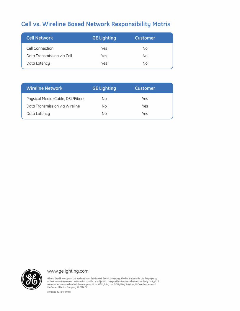
www.gelighting.comGE and the GE Monogram are trademarks of the General Electric Company. All other trademarks are the property of their respective owners. Information provided is subject to change without notice. All values are design or typical values when measured under laboratory conditions. GE Lighting and GE Lighting Solutions, LLC are businesses of the General Electric Company. © 2014 GE.
CTRL004 (Rev 09/08/14)
Cell vs. Wireline Based Network Responsibility Matrix
Cell Network GE Lighting Customer
Cell Connection Yes No
Data Transmission via Cell Yes No
Data Latency Yes No
Wireline Network GE Lighting Customer
Physical Media (Cable, DSL/Fiber) No Yes
Data Transmission via Wireline No Yes
Data Latency No Yes

GE Lighting
DescriptionLightGrid™ Outdoor Wireless Control System from GE allows remote monitoring and control, utility-grade energy measurement and GPS mapping of streetlights.The Central management Server can hosted by GE Lighting or Installed at Customer site. While both options offer best in class features and benefits, the hosted solution offers additional advantages of shortest possible install time, with no involvement of customer IT while delivering proven cost savings over installed solution
LightGrid™ Hosting
Applications• Street Lighting• Area Lighting
Outdoor Wireless Control System
Hosted or Installed Solution• Individual or Group remote monitoring and control• Manual or Automatic dimming based on schedules• Automated fault email notifications• Real-time lighting information• Customized reporting and user access level management• High level of security encryption• User-friendly, Intuitive software for analytics

www.gelighting.comGE and the GE Monogram are trademarks of the General Electric Company. All other trademarks are the property of their respective owners. Information provided is subject to change without notice. All values are design or typical values when measured under laboratory conditions. GE Lighting and GE Lighting Solutions, LLC are businesses of the General Electric Company. © 2014 GE.
CTRL005 (Rev 09/08/14)
Hosted vs. Installed Solution Responsibility Matrix
Hosted Solution GE Lighting Customer
Data Back Up Yes No
Software Upgrades Installation Yes No
Server Yes No
IT Support Yes No
Other (Electricity, Air Conditioning, Server Room, Security...) Yes No
Installed Solution GE Lighting Customer
Data Back Up No Yes
Software Upgrades Installation No Yes
Server No Yes
IT Support No Yes
Other (Electricity, Air Conditioning, Server Room, Security...) No Yes

GE Lighting
LightGrid™ Network DesignOutdoor Wireless Control System
Cell Based Network
Gateway
Cellular modem
GE Web Application
Central Management System
Fixture
Node
Wireline Based Network
Gateway
Modem
Router
GE Web Application
Central Management System
Fixture
Node
1. How does the LightGrid™ system work?The architecture diagram below gives an overview of the LightGrid™ system. • Nodes reside on top of each Light Fixture. • Nodes operate in a Mesh Network and communicate to the Gateway• Nodes collect data (Voltage, Current…) for the respective fixture and send this information to the Central Management Server (CMS) via a Gateway• The backhaul Network can be wireline or cell based• The CMS can be installed at the customer site or hosted by GE Lighting• The fixtures can be remotely configured, monitored and controlled (Turn on/off/dim..) by sending commands to the nodes via the Gateway from the CMS

www.gelighting.comGE and the GE Monogram are trademarks of the General Electric Company. All other trademarks are the property of their respective owners. Information provided is subject to change without notice. All values are design or typical values when measured under laboratory conditions. GE Lighting and GE Lighting Solutions, LLC are businesses of the General Electric Company. © 2014 GE.
CTRL007 (Rev 09/10/14)
2. Why is Network Design Critical for LightGrid™ Network?LightGrid™ network works on IEEE 802.15.4 6LoWPAN Mesh Network. In order for the nodes and the gateway to reliably communicate with each other – it is critical to optimize the placement of the Gateways at the right locations. GE Lighting’s Scientists and Engineers have developed sophisticated algorithms to simulate the Mesh Network based on the application needs. These simulations will help determine the optimum number of gateways and placement locations for the gateways.
3. What are the factors that affect the Mesh Network?Several factors such as distance between two nodes, distance between nodes and gateway, installation height of gateways, obstructions such as buildings and trees between the nodes and the gateway etc. can affect the Mesh Network.
4. How does a Mesh Network look in Real Life?Here a typical example of how a mesh network will look in real life.
5. Is Network design needed for every installation?It is advisable do a design for all installations so that the optimum number of gateways and installation locations for gateways can be determined to ensure reliable operation of the mesh network.
6. Will GE Lighting do the LightGrid™ Network Design for my site?Yes. GE Lighting will gladly do the Network Design for your site.
7. What information does GE Lighting need to do the Network Design?GE Lighting will need the co-ordinates of the Light Fixtures where the LightGrid™ nodes will be installed to do the Network Design.
8. If I don’t have the coordinates – is there any way GE Lighting can do the network design?While the simulation results are more accurate with the actual coordinates of the Light Fixtures, GE Lighting can do the network design based on the site location information. Please contact us as [email protected] so that our Customer Service Expert can get in touch with you to get more details about your site.

GE Lighting
LightGrid™ Stand-Alone NodeOutdoor Wireless Control System
E L WN G 5 S _ _ _ _ _ _ _ _ _ _ _
PRODUCTID
VOLTAGE(UL)
PINCONFIGURATION
D = GE DimmingN = Non DimmingA = ANSI Dimming
0 = 120/2775 = 480 D = 347
R = 2% Revenue GradeG = General GradeU = 0.5% Utility GradeN = N/A
GPSPINS METERING OPTIONS
G = GPS CapabilityN = N/A
E L W N X = Future Use5 = 5 Pin
MAXWATTAGE
5 = 500 watts max loadX = Future Use
S = Stand Alone
1. Will LightGrid™ operate in Stand-Alone mode?Yes
2. What are the functionalities of the stand-alone LightGrid™ node?Stand-alone LightGrid™ node will have the Photocell functionality (on at Dusk and off at dawn…based on ambient lighting). Standalone LightGrid™ node will also provide dimming functionality.
5. What is the ordering code for LightGrid™ Stand-Alone Node?Same as the standard LightGrid™ node with an “S” at the end.
3. How will dimming functionality work?LightGrid™ Stand-Alone Node – offers 2 flexible dimming options 1. Dimming schedule can be pre-programmed at the factory. For example: 100% Light output for 6 hours after turn on by Photocell and 50% light output for the next 6 hours 2. Dimming schedule can be programmed at the site by a mobile gateway. This is a one-time activity during initial installation. If at any point in future the dimming schedule needs to be altered, this is possible again with a new commissioning request.
4. Why should I install LightGrid™ Stand-Alone Node?LightGrid™ Stand-Alone Node offers the flexibility of changing the dimming schedule at a future date without the need to physically access the node.
LightGrid™ Stand-Alone Node is “Network Ready”. In future if there is a need to do remote monitoring, control, measurements…there is no need to change the node. These features can be accomplished by installing the right number of gateways at the right location for the nodes to automatically join the network and be visible in the LightGrid™ Web Application.
www.gelighting.comGE and the GE Monogram are trademarks of the General Electric Company. All other trademarks are the property of their respective owners. Information provided is subject to change without notice. All values are design or typical values when measured under laboratory conditions. GE Lighting and GE Lighting Solutions, LLC are businesses of the General Electric Company. © 2014 GE.
CTRL008 (Rev 09/10/14)

GE Lighting
DescriptionLightGrid™ Outdoor Wireless Control System from GE allows remote monitoring and control, utility-grade energy measurement and GPS mapping of streetlights.
LightGrid™ Cell ModemOutdoor Wireless Control System
Specifications Input Voltage: 120-277V, 347V—480V Weight: 8 lbs Dimensions: 15 in. x 13 in. x 7 in Mounting Height: 27 ft.–40 ft. Warranty: 3 years
Packaging Cellular enclosure (1pc) Conduit fitting (2pcs, mounted to enclosure) Flexible conduit (2pc) Power cable, stripped ends (1pc) Ethernet cable (1pc) Pole mounting bracket (2pcs, mounted to enclosure)
Cell Based Network
Gateway
Cellular modem
GE Web Application
Central Management System
Fixture
Node
Ordering Number Logic
E L W M O C X _ _ _ _ _ _ _ _
PRODUCTID
0 = 120-277 V = VerizonR = RogersX = Future Use
C = CAT 5 Cable only X
VOLTAGE PROVIDER
E L W M
IPCOMMUNICATION
FUTUREUSE
Applications Street Lighting Area Lighting
Cell Modem

www.gelighting.comGE and the GE Monogram are trademarks of the General Electric Company. All other trademarks are the property of their respective owners. Information provided is subject to change without notice. All values are design or typical values when measured under laboratory conditions. GE Lighting and GE Lighting Solutions, LLC are businesses of the General Electric Company. © 2015 GE.
CTRL009 (Rev 06/10/15)
Mounting Gateway and CellularCarefully unpack unit from its packaging. Properly inspect for defects before installing.
Before attaching gateway enclosure to pole, ensure the mount band clamps are correctly oriented. NOTE: Adjustable steel band allowsmounting on pole diameters up to 15 inches.
Install GPS and antenna into bracket and tighten bolt (45 lbs-in. torque).
Attach gateway enclosure to pole bytightening steel band clamps. Fold or trim excess metal band if needed.
Position cellular enclosure below the gateway enclosure and attach to pole by tightening both steel band clamps. NOTE: The distance (A) between the two enclosures should be adjusted to accommodate the length of the Ethernet cable and power in/out cable.
Insert GPS and antenna wires through two glands in bottom of gateway enclosure.
Install two 0.75-inch diameter nonmetallic Type B liquid-tight conduit between gateway and cellular enclosures.
1
4
2
5
3
6

GE Lighting
DescriptionLightGrid™ Outdoor Wireless Control System from GE allows remote monitoring and control, utility-grade energy measurement and GPS mapping of streetlights.
LightGrid™ Products & ServicesOutdoor Wireless Control System
Applications Street Lighting Area Lighting
Fixed Initial Products & ServicesNode Yes Yes Yes Yes Gateway Yes Yes Yes Yes Cell Modem Yes NA Yes NA Software License Yes Yes Yes Yes Training Yes Yes Yes Yes Commissioning Yes Yes Yes Yes IT Interface Evaluation NA NA Yes Yes Recurring Services (Monthly/Annual)Hosting Services Yes Yes NA NA Cell Data Services Yes NA Yes NANetwork Management Service Yes Yes Yes YesSoftware Annual Maintenance Yes Yes Yes Yes
HOSTED/CELL
CMS/BACKHAUL
HOSTED/WIRELINE*
INSTALLED/**CELL
INSTALLED/**WIRELINE*
Gateway
Cellular modemWebApplication
Fixture
Node
WirelineBackhaul
www.gelighting.comGE and the GE Monogram are trademarks of the General Electric Company. All other trademarks are the property of their respective owners. Information provided is subject to change without notice. All values are design or typical values when measured under laboratory conditions. GE Lighting and GE Lighting Solutions, LLC are businesses of the General Electric Company. © 2014 GE.
CTRL010 (Rev 12/15/14)
*Wireline Solution: Customer to provide Wireline Network, Switches/Routers and RJ45/Cat 5+/Single VLAN Connection.**Installed Solution: Customer to provide server, router, switches and access through firewall.
CentralManagementSystem

1
Table of Contents
RIPLEY l i g h t i n gcontrols
Division of SouthConn Technologies Inc
Phone: 803-939-4700Fax: 803-939-4777E-mail: [email protected]
www.RipleyLC.com
Twist-Lock Electronic PhotocontrolTru-Filter®
With True-Filter®, Turn-ON / Turn-OFF events occur with much greater precision than that of competitor models utilizing silicon
through the sensor window, not ALL sources—they eventually cause a shift of Turn-ON / Turn-OFF light levels—they fade over time due to UV
Ripley’s line-up of exclusive Tru-Filter® InfraRed-
Filtering Photocontrols
each Tru-Filter® photocontrol, sources of infrared to mirror the spectral
sensitivity of the human eye, and provide highly accurate control across the entire visual light
spectrum.
Other Exclusive Features:
Double-Sided Plated-Through Circuit Board (DSPT) for durability and reliability,
Dual Zener Diodes, High Impact Thermoplastic Base, Solid Brass Contact Blades, UV Stabilized Permanent Color, High Impact Resistant Polypropylene Cover
Meets or exceeds rigid quality requirements of
SouthConn Technologies Inc. and applicable ANSI C136.10,
and C136.24 Standards
RipT
eachour
ensiseaccupec
es
sea
sp
h TruWithTurnevenmuc
WithHuman Eye Silicon PhotodetectorTru-Filter
Wavelength (nm)
100
80
60
40
20
0400 500 600 700 800 900 1000 1100
Rela
tive
Spe
ctra
l Sen
sitiv
ity (
%)
Tru-Filter® spectral sensitivity matches that of the Human Eye; while competitor’s Silicon Photodetector comes nowhere close.
TruFilter® models are available for 60 Hz Nominal Voltage applications, including: Multi-volt (120/208/240/277), 120 Volt, 240 Volt, 480 Volt, and 347 Volt
PS-6100-046 Tru-Filter Overview 021511 Rev. 1
WARRANTY: 8 years from date of manufacture

Phone: 803-939-4700Fax: 803-939-4777E-mail: [email protected]
www.RipleyLC.com
RIPLEY l i g h t i n gcontrols
Division of SouthConn Technologies Inc
2
6390TF 6246TF 6372TF 6394TF 6395TFNominal Voltage 50/60 Hz 120/208/240/277 120 240 480 347
Voltage Range 105—305 105—135 200—300 432-528 312-382
Fail Mode On (contacts normally closed)
Load Rating 1000 Watt Tungsten / 1800 VA Ballast
Operating Temperature -40C to +70C (-40F to +158F)
Photocell Infrared Filtering Silicon Phototransistor *
Dielectric Strength 5000 Volts between current carrying parts and metal surfaces
Surge Protection 320 Joule MOV 10,000 amp surge current
530 Joule MOV 10,000 amp surge current
Power Consumption 0.5 watts @ 120 V
Time Delay Off (Instant On) 3 to 5 seconds
Operating Light Levels (Standard Settings) Turn On 1.5 FC ± .25 / Turn Off by 2.25 FC / (Off:On Ratio = 1.5:1)
High Impact / High Temperature Thermoplastic Base Temperature Rating 125° C
ANSI Color Coded Cover Blue Gray Maroon Yellow Green
Options Option Code 1 (Add to end of Model Number)
430 Joule MOV / 13,000 amp -X -X -X N/A N/A
Fail Off -FO -FO -FO N/A N/A
ANSI Color Coded Cap Options Option Code 2 (Add to end of Model Number, after Option Code 1)
Green -GN -GN -GN N/A N/A
Black -BK -BK -BK N/A N/A
Brown -BN -BN -BN N/A N/A
Orange -ORN -ORN -ORN N/A N/A
Operating Light Levels Option Option Code 3 (Add to end of Model Number, after Option Code 2)
Denotes Turn On point in FC Specify 0.3—5.0 FC
Twist-Lock Electronic PhotocontrolTru-Filter® Model Selection
PS-6100-047Tru-Filter Models013012Rev. 2
Tru-Filter® InfraRed-Filtering Photocontrols
Model Selection
* Photosensor pigment varies with lot source coding and has no effect on performanceWARRANTY: 8 years from date of manufacture