propeller owner's manual - hartzell propeller inc...
TRANSCRIPT
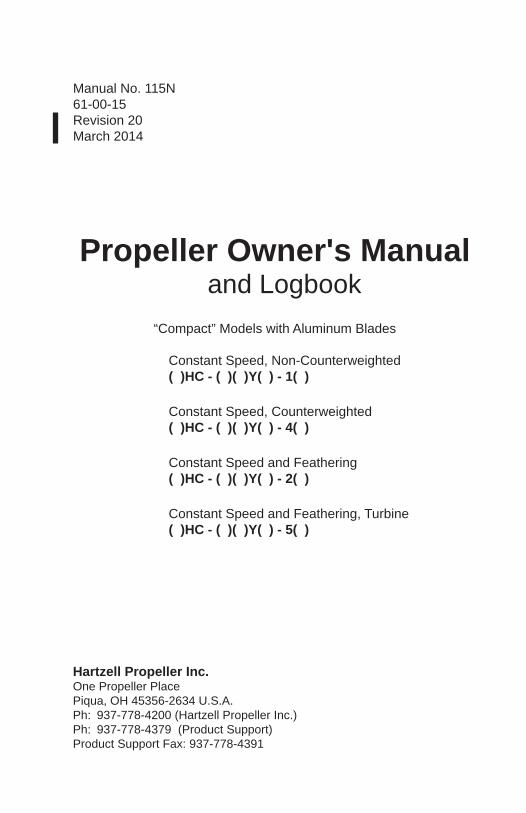
Manual No. 115N61-00-15Revision 20March 2014
Propeller Owner's Manual and Logbook
“Compact” Models with Aluminum Blades
Constant Speed, Non-Counterweighted ( )HC - ( )( )Y( ) - 1( )
Constant Speed, Counterweighted ( )HC - ( )( )Y( ) - 4( )
Constant Speed and Feathering ( )HC - ( )( )Y( ) - 2( )
Constant Speed and Feathering, Turbine ( )HC - ( )( )Y( ) - 5( )
Hartzell Propeller Inc.One Propeller PlacePiqua, OH 45356-2634 U.S.A.Ph: 937-778-4200 (Hartzell Propeller Inc.)Ph: 937-778-4379 (Product Support)Product Support Fax: 937-778-4391
Propeller Owner's Manual115N
61-00-15 COVERInside Cover
Rev. 20 Mar/14
(This page is intentionally blank.)
© 1999, 2000, 2002, 2003, 2004, 2005, 2006, 2009, 2012, 2013, 2014 - Hartzell Propeller Inc. - All rights reserved
Page 1 Rev. 6 Sep/00
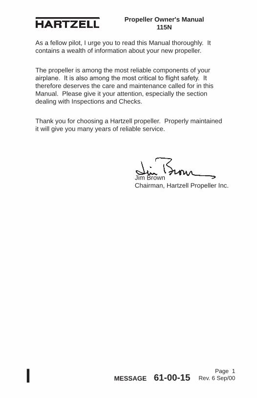
Propeller Owner's Manual 115N
MESSAGE 61-00-15
As a fellow pilot, I urge you to read this Manual thoroughly. It contains a wealth of information about your new propeller.
The propeller is among the most reliable components of your airplane. It is also among the most critical to flight safety. It therefore deserves the care and maintenance called for in this Manual. Please give it your attention, especially the section dealing with Inspections and Checks.
Thank you for choosing a Hartzell propeller. Properly maintained it will give you many years of reliable service.
Jim Brown Chairman, Hartzell Propeller Inc.
Page 2 Rev. 6 Sep/00MESSAGE 61-00-15
Propeller Owner's Manual 115N
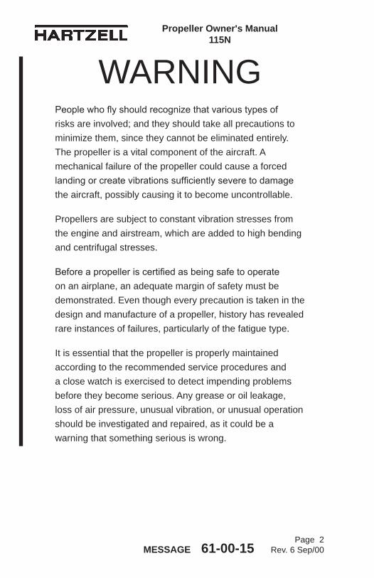
WARNINGPeople who fly should recognize that various types of risks are involved; and they should take all precautions to minimize them, since they cannot be eliminated entirely. The propeller is a vital component of the aircraft. A mechanical failure of the propeller could cause a forced landing or create vibrations sufficiently severe to damage the aircraft, possibly causing it to become uncontrollable.
Propellers are subject to constant vibration stresses from the engine and airstream, which are added to high bending and centrifugal stresses.
Before a propeller is certified as being safe to operate on an airplane, an adequate margin of safety must be demonstrated. Even though every precaution is taken in the design and manufacture of a propeller, history has revealed rare instances of failures, particularly of the fatigue type.
It is essential that the propeller is properly maintained according to the recommended service procedures and a close watch is exercised to detect impending problems before they become serious. Any grease or oil leakage, loss of air pressure, unusual vibration, or unusual operation should be investigated and repaired, as it could be a warning that something serious is wrong.
Page 3 Rev. 6 Sep/00
Propeller Owner's Manual 115N
MESSAGE 61-00-15
For operators of uncertified or experimental aircraft an even greater level of vigilance is required in the maintenance and inspection of the propeller. Experimental installations often use propeller-engine combinations that have not been tested and approved. In these cases, the stress on the propeller and, therefore, its safety margin is unknown. Failure could be as severe as loss of propeller or propeller blades and cause loss of propeller control and/or loss of aircraft control.
Hartzell Propeller Inc. follows FAA regulations for propeller certification on certificated aircraft. Experimental aircraft may operate with unapproved engines or propellers or engine modifications to increase horsepower, such as unapproved crankshaft damper configurations or high compression pistons. These issues affect the vibration output of the engine and the stress levels on the propeller. Significant propeller life reduction and failure are real possibilities.
Frequent inspections are strongly recommended if operating with a non-certificated installation; however, these inspections may not guarantee propeller reliability, as a failing device may be hidden from the view of the inspector. Propeller overhaul is strongly recommended to accomplish periodic internal inspection.
Visually inspect metal blades for cracks. Inspect hubs, with particular emphasis on each blade arm for cracks. Eddy current equipment is recommended for hub inspection, since cracks are usually not apparent.

Page 4 Rev. 6 Sep/00MESSAGE 61-00-15
Propeller Owner's Manual 115N
(This page is intentionally blank.)
Propeller Owner's Manual 115N
Page 5 Rev. 20 Mar/14 REVISION HIGHLIGHTS 61-00-15
REVISION HIGHLIGHTSRevision 20, dated March 2014, incorporates the following:• COVER:
• Revisedtomatchthemanualrevision
• REVISIONHIGHLIGHTS: • Revisedtomatchthemanualrevision
• LISTOFEFFECTIVEPAGES: • Revisedtomatchthemanualrevision
• DESCRIPTIONANDOPERATION: • Revisedthesection"ModelDesignation"
• INSTALLATIONANDREMOVAL: • RevisedTable3-1,"TorqueTable" • RevisedFigure3-12,"Two-PieceSpinnerMounting (Procedure2)"
• TESTINGANDTROUBLESHOOTING • Revisedthesection"OperationalTests"

Page 6 Rev. 20 Mar/14 REVISION HIGHLIGHTS 61-00-15
Propeller Owner's Manual 115N
(Thispageisintentionallyblank.)
Propeller Owner's Manual 115N
Page 7 Rev. 20 Mar/14 REVISION HIGHLIGHTS 61-00-15
REVISIONS HIGHLIGHTS
1. IntroductionA. General
Thisisalistofcurrentrevisionsthathavebeenissuedagainstthismanual.PleasecompareittotheRECORDOFREVISIONSpagetoensurethatallrevisionshavebeenaddedtothemanual.
B. Components(1) RevisionNo.indicatestherevisionsincorporatedinthis
manual.(2) IssueDateisthedateoftherevision.(3) Commentsindicatestheleveloftherevision.
(a) NewIssueisanewmanualdistribution.Themanualisdistributedinitsentirety.Allthepagerevisiondatesarethesameandnochangebarsareused.
(b) Reissueisarevisiontoanexistingmanualthatincludesmajorcontentand/ormajorformatchanges.Themanualisdistributedinitsentirety.Allthepagerevisiondatesarethesameandnochangebarsareused.
(c) MajorRevisionisarevisiontoanexistingmanualthatincludesmajorcontentorminorcontentchangesoveralargeportionofthemanual.Themanualisdistributedinitsentirety.Allthepagerevisiondatesarethesame,butchangebarsareusedtoindicatethe changes incorporated in the latest revision of the manual.
(d) MinorRevisionisarevisiontoanexistingmanualthatincludesminorcontentchangestothemanual.Onlytherevisedpagesofthemanualaredistributed.Eachpageretainsthedateandthechangebarsassociated with the last revision to that page.
Page 8 Rev. 20 Mar/14 REVISION HIGHLIGHTS 61-00-15
Propeller Owner's Manual 115N
Revision No. IssueDate Comments Rev.5 Jan/99 MajorRevision Rev. 6 Sep/00 Minor Revision Rev.7 Oct/02 MajorRevision Rev.8 Jun/03 MinorRevision Rev.9 Aug/03 MinorRevision Rev.10 Nov/03 MinorRevision Rev.11 Dec/04 MinorRevision Rev.12 Apr/05 MinorRevision Rev.13 Aug/06 MinorRevision Rev. 14 Jan/09 Minor Revision Rev.15 Jul/09 MinorRevision Rev. 16 Oct/09 Minor Revision Rev.17 Jul/12 MinorRevision Rev.18 Feb/13 MinorRevision Rev.19 Nov/13 MinorRevision Rev. 20 Mar/14 Minor Revision
RECORD OF REVISIONS
Rev. No. Issue Date Date Inserted Inserted By
Propeller Owner's Manual 115N
Page 9 Rev. 6 Sep/00RECORD OF REVISIONS 61-00-15
7 Oct/02 Oct/02 HPI
8 Jun/03 Jun/03 HPI
9 Jul/03 Jul/03 HPI
10 Nov/03 Nov/03 HPI
11 Dec/04 Dec/04 HPI
12 Apr/05 Apr/05 HPI
13 Aug/06 Aug/06 HPI
14 Jan/09 Jan/09 HPI
15 Jul/09 Aug/09 HPI
16 Oct/09 Oct/09 HPI
17 Jul/12 Jul/12 HPI
18 Feb/13 Feb/13 HPI
19 Nov/13 Nov/13 HPI
20 Mar/14 Mar/14 HPI
Page 10 Rev. 6 Sep/00RECORD OF REVISIONS 61-00-15
RECORD OF REVISIONS
Rev. No. Issue Date Date Inserted Inserted By
Propeller Owner's Manual 115N
Page 11 Rev. 6 Sep/00
RECORD OF TEMPORARY REVISIONS TR Issue Date Inserted Date Removed No. Date Inserted By Removed By
Propeller Owner's Manual 115N
RECORD OF TEMPORARY REVISIONS 61-00-15
Page 12 Rev. 6 Sep/00RECORD OF TEMPORARY REVISIONS 61-00-15
RECORD OF TEMPORARY REVISIONS TR Issue Date Inserted Date Removed No. Date Inserted By Removed By
Propeller Owner's Manual 115N
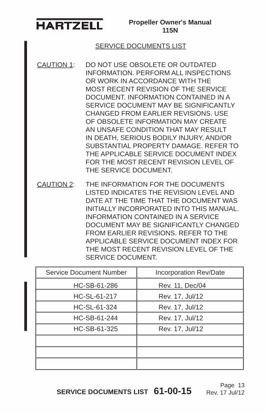
SERVICE DOCUMENTS LIST
Page 13 Rev. 17 Jul/12
Propeller Owner's Manual 115N
SERVICE DOCUMENTS LIST 61-00-15
CAUTION 1: DO NOT USE OBSOLETE OR OUTDATED INFORMATION. PERFORM ALL INSPECTIONS OR WORK IN ACCORDANCE WITH THE MOST RECENT REVISION OF THE SERVICE DOCUMENT. INFORMATION CONTAINED IN A SERVICE DOCUMENT MAY BE SIGNIFICANTLY CHANGED FROM EARLIER REVISIONS. USE OF OBSOLETE INFORMATION MAY CREATE AN UNSAFE CONDITION THAT MAY RESULT IN DEATH, SERIOUS BODILY INJURY, AND/OR SUBSTANTIAL PROPERTY DAMAGE. REFER TO THE APPLICABLE SERVICE DOCUMENT INDEX FOR THE MOST RECENT REVISION LEVEL OF THE SERVICE DOCUMENT.
CAUTION 2: THE INFORMATION FOR THE DOCUMENTS LISTED INDICATES THE REVISION LEVEL AND DATE AT THE TIME THAT THE DOCUMENT WAS INITIALLY INCORPORATED INTO THIS MANUAL. INFORMATION CONTAINED IN A SERVICE DOCUMENT MAY BE SIGNIFICANTLY CHANGED FROM EARLIER REVISIONS. REFER TO THE APPLICABLE SERVICE DOCUMENT INDEX FOR THE MOST RECENT REVISION LEVEL OF THE SERVICE DOCUMENT.
Service Document Number Incorporation Rev/Date
HC-SB-61-286 Rev. 11, Dec/04HC-SL-61-217 Rev. 17, Jul/12HC-SL-61-324 Rev. 17, Jul/12HC-SB-61-244 Rev. 17, Jul/12HC-SB-61-325 Rev. 17, Jul/12
Page 14 Rev. 7 Oct/02SERVICE DOCUMENTS LIST 61-00-15
SERVICE DOCUMENTS LIST
Propeller Owner's Manual 115N
Service Document Number Incorporation Rev/Date
Propeller Owner's Manual 115N
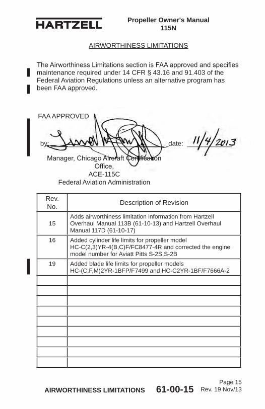
Page 15 Rev. 19 Nov/13AIRWORTHINESS LIMITATIONS 61-00-15
Rev. No. Description of Revision
15Adds airworthiness limitation information from Hartzell Overhaul Manual 113B (61-10-13) and Hartzell Overhaul Manual 117D (61-10-17)
16 Added cylinder life limits for propeller model HC-C(2,3)YR-4(B,C)F/FC8477-4R and corrected the engine model number for Aviatt Pitts S-2S,S-2B
19 Added blade life limits for propeller models HC-(C,F,M)2YR-1BFP/F7499 and HC-C2YR-1BF/F7666A-2
AIRWORTHINESS LIMITATIONS
The Airworthiness Limitations section is FAA approved and specifies maintenance required under 14 CFR § 43.16 and 91.403 of the Federal Aviation Regulations unless an alternative program has been FAA approved.
FAA APPROVED
by: ______________________________ date: ____________
Manager, Chicago Aircraft Certification Office,
ACE-115CFederal Aviation Administration
Page 16 Rev. 19 Nov/13AIRWORTHINESS LIMITATIONS 61-00-15
Propeller Owner's Manual115N
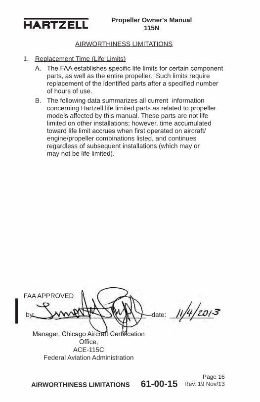
1. Replacement Time (Life Limits)A. The FAA establishes specific life limits for certain component
parts, as well as the entire propeller. Such limits require replacement of the identified parts after a specified number of hours of use.
B. The following data summarizes all current information concerning Hartzell life limited parts as related to propeller models affected by this manual. These parts are not life limited on other installations; however, time accumulated toward life limit accrues when first operated on aircraft/engine/propeller combinations listed, and continues regardless of subsequent installations (which may or may not be life limited).
AIRWORTHINESS LIMITATIONS
FAA APPROVED
by: ______________________________ date: ____________
Manager, Chicago Aircraft Certification Office,
ACE-115CFederal Aviation Administration
Propeller Owner's Manual 115N
Page 17 Rev. 19 Nov/13AIRWORTHINESS LIMITATIONS 61-00-15
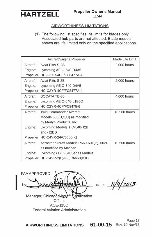
(1) The following list specifies life limits for blades only. Associated hub parts are not affected. Blade models shown are life limited only on the specified applications.
Aircraft/Engine/Propeller Blade Life LimitAircraft: Aviat Pitts S-2S Engine: Lycoming AEIO-540-D4A5 Propeller: HC-C2YR-4CF/FC8477A-4
2,000 hours
Aircraft: Aviat Pitts S-2B Engine: Lycoming AEIO-540-D4A5 Propeller: HC-C2YR-4CF/FC8477A-4
2,000 hours
Aircraft: SOCATA TB-30 Engine: Lycoming AEIO-540-L1B5D Propeller: HC-C2YR-4CF/FC8475-6
4,000 hours
Aircraft: Twin Commander Aircraft Models 500(B,S,U) as modified by Merlyn Products, Inc. Engine: Lycoming Models TIO-540-J2B and -J2BD Propeller: HC-C4YR-2/FC6660(K)
10,500 hours
Aircraft: Aerostar aircraft Models PA60-601(P), 602P as modified by Machen Engine: Lycoming (T)IO-540Series Models Propeller: HC-C4YR-2(L)/F(J)C6660(B,K)
10,500 hours
AIRWORTHINESS LIMITATIONS
FAA APPROVED
by: ______________________________ date: ____________
Manager, Chicago Aircraft Certification Office,
ACE-115CFederal Aviation Administration
Page 18 Rev. 19 Nov/13AIRWORTHINESS LIMITATIONS 61-00-15
Propeller Owner's Manual115N
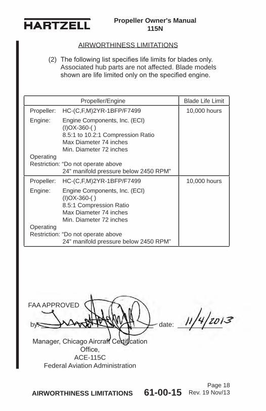
Propeller/Engine Blade Life LimitPropeller: HC-(C,F,M)2YR-1BFP/F7499Engine: Engine Components, Inc. (ECI) (I)OX-360-( ) 8.5:1 to 10.2:1 Compression Ratio Max Diameter 74 inches Min. Diameter 72 inches Operating Restriction: “Do not operate above 24” manifold pressure below 2450 RPM”
10,000 hours
Propeller: HC-(C,F,M)2YR-1BFP/F7499Engine: Engine Components, Inc. (ECI) (I)OX-360-( ) 8.5:1 Compression Ratio Max Diameter 74 inches Min. Diameter 72 inches Operating Restriction: “Do not operate above 24” manifold pressure below 2450 RPM”
10,000 hours
FAA APPROVED
by: ______________________________ date: ____________
Manager, Chicago Aircraft Certification Office,
ACE-115CFederal Aviation Administration
(2) The following list specifies life limits for blades only. Associated hub parts are not affected. Blade models shown are life limited only on the specified engine.
AIRWORTHINESS LIMITATIONS
Propeller Owner's Manual 115N
Page 19 Rev. 19 Nov/13AIRWORTHINESS LIMITATIONS 61-00-15
FAA APPROVED
by: ______________________________ date: ____________
Manager, Chicago Aircraft Certification Office,
ACE-115CFederal Aviation Administration
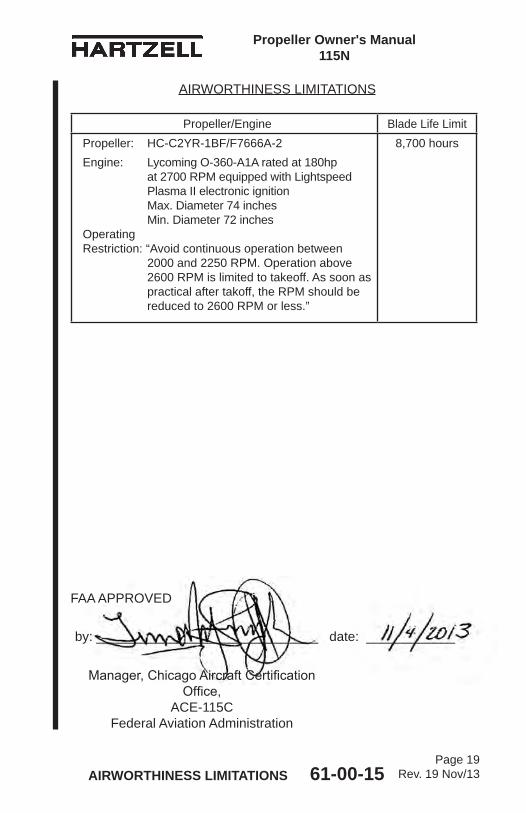
Propeller/Engine Blade Life LimitPropeller: HC-C2YR-1BF/F7666A-2Engine: Lycoming O-360-A1A rated at 180hp at 2700 RPM equipped with Lightspeed Plasma II electronic ignition Max. Diameter 74 inches Min. Diameter 72 inches Operating Restriction: “Avoid continuous operation between 2000 and 2250 RPM. Operation above 2600 RPM is limited to takeoff. As soon as practical after takoff, the RPM should be reduced to 2600 RPM or less.”
8,700 hours
AIRWORTHINESS LIMITATIONS
Page 20 Rev. 19 Nov/13AIRWORTHINESS LIMITATIONS 61-00-15
Propeller Owner's Manual115N
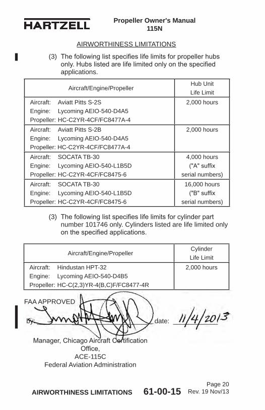
(3) The following list specifies life limits for propeller hubs only. Hubs listed are life limited only on the specified applications.
(3) The following list specifies life limits for cylinder part number 101746 only. Cylinders listed are life limited only on the specified applications.
AIRWORTHINESS LIMITATIONS
Aircraft/Engine/PropellerHub Unit Life Limit
Aircraft: Aviatt Pitts S-2S Engine: Lycoming AEIO-540-D4A5 Propeller: HC-C2YR-4CF/FC8477A-4
2,000 hours
Aircraft: Aviatt Pitts S-2B Engine: Lycoming AEIO-540-D4A5 Propeller: HC-C2YR-4CF/FC8477A-4
2,000 hours
Aircraft: SOCATA TB-30 Engine: Lycoming AEIO-540-L1B5D Propeller: HC-C2YR-4CF/FC8475-6
4,000 hours ("A" suffix
serial numbers)Aircraft: SOCATA TB-30 Engine: Lycoming AEIO-540-L1B5D Propeller: HC-C2YR-4CF/FC8475-6
16,000 hours ("B" suffix
serial numbers)
FAA APPROVED
by: ______________________________ date: ____________
Manager, Chicago Aircraft Certification Office,
ACE-115CFederal Aviation Administration
Aircraft/Engine/PropellerCylinder Life Limit
Aircraft: Hindustan HPT-32 Engine: Lycoming AEIO-540-D4B5 Propeller: HC-C(2,3)YR-4(B,C)F/FC8477-4R
2,000 hours
LIST OF EFFECTIVE PAGES
Propeller Owner's Manual 115N
Chapter Page Revision Date
LIST OF EFFECTIVE PAGES 61-00-15Page 21
Rev. 20 Mar/14
Cover Cover and Inside Cover Rev. 20 Mar/14Message 1 thru 4 Rev. 6 Sep/00Revision Highlights 5 thru 8 Rev. 20 Mar/14Record of Revisions 9 and 10 Rev. 6 Sep/00Record of Temporary Revisions 11 and 12 Rev. 6 Sep/00Service Documents List 13 Rev. 17 Jul/12Service Documents List 14 Rev. 7 Oct/02Airworthiness Limitations 15 thru 20 Rev. 19 Nov/13List of Effective Pages 21 thru 24 Rev. 20 Mar/14Table of Contents 25 thru 34 Rev. 19 Nov/13Introduction 1-1 thru 1-4 Rev. 18 Feb/13Introduction 1-5 thru 1-16 Rev. 17 Jul/12Description and Operation 2-1 Rev. 17 Jul/12Description and Operation 2-2 Rev. 14 Jan/09Description and Operation 2-3 thru 2-12 Rev. 13 Aug/06Description and Operation 2-13 Rev. 14 Jan/09Description and Operation 2-14 Rev. 13 Aug/06Description and Operation 2-15 Rev. 7 Oct/02Description and Operation 2-16 Rev. 20 Mar/14Description and Operation 2-17 Rev. 12 Apr/05Description and Operation 2-18 Rev. 15 Jul/09Description and Operation 2-19 Rev. 12 Apr/05Description and Operation 2-20 Rev. 20 Mar/14Description and Operation 2-21 and 2-22 Rev. 16 Oct/09Description and Operation 2-23 Rev. 12 Apr/05Description and Operation 2-24 Rev. 16 Oct/09Description and Operation 2-25 and 2-26 Rev. 17 Jul/12Description and Operation 2-27 and 2-28 Rev. 14 Jan/09Description and Operation 2-29 thru 2-31 Rev. 17 Jul/12Description and Operation 2-32 Rev. 12 Apr/05Installation and Removal 3-1 Rev. 17 Jul/12Installation and Removal 3-2 Rev. 14 Jan/09Installation and Removal 3-3 Rev. 17 Jul/12Installation and Removal 3-4 Rev. 14 Jan/09Installation and Removal 3-5 Rev. 17 Jul/12Installation and Removal 3-6 Rev. 14 Jan/09Installation and Removal 3-7 Rev. 20 Mar/14Installation and Removal 3-8 Rev. 14 Jan/09
LIST OF EFFECTIVE PAGES 61-00-15Page 22
Rev. 20 Mar/14
Propeller Owner's Manual 115N
LIST OF EFFECTIVE PAGES
Chapter Page Revision Date
Installation and Removal 3-9 Rev. 17 Jul/12Installation and Removal 3-10 Rev. 14 Jan/09Installation and Removal 3-11 Rev. 17 Jul/12Installation and Removal 3-12 Rev. 14 Jan/09Installation and Removal 3-13 Rev. 17 Jul/12Installation and Removal 3-14 Rev. 14 Jan/09Installation and Removal 3-15 Rev. 17 Jul/12Installation and Removal 3-16 Rev. 14 Jan/09Installation and Removal 3-17 Rev. 17 Jul/12Installation and Removal 3-18 Rev. 15 Jul/09Installation and Removal 3-19 and 3-20 Rev. 14 Jan/09Installation and Removal 3-21 Rev. 17 Jul/12Installation and Removal 3-22 Rev. 14 Jan/09Installation and Removal 3-23 and 3-24 Rev. 17 Jul/12Installation and Removal 3-25 and 3-26 Rev. 14 Jan/09Installation and Removal 3-27 Rev. 17 Jul/12Installation and Removal 3-28 Rev. 14 Jan/09Installation and Removal 3-29 and 3-30 Rev. 17 Jul/12Installation and Removal 3-31 Rev. 14 Jan/09Installation and Removal 3-32 Rev. 17 Jul/12Installation and Removal 3-33 and 3-34 Rev. 14 Jan/09Installation and Removal 3-35 Rev. 17 Jul/12Installation and Removal 3-36 Rev. 14 Jan/09Installation and Removal 3-37 thru 3-42 Rev. 17 Jul/12Installation and Removal 3-43 Rev. 20 Mar/14Installation and Removal 3-44 thru 3-49 Rev. 17 Jul/12Installation and Removal 3-50 Rev. 20 Mar/14Installation and Removal 3-51- thru 3-53 Rev. 17 Jul/12Installation and Removal 3-54 Rev. 14 Jan/09Installation and Removal 3-55 Rev. 17 Jul/12Installation and Removal 3-56 Rev. 14 Jan/09Installation and Removal 3-57 Rev. 17 Jul/12Installation and Removal 3-58 Rev. 14 Jan/09Installation and Removal 3-59 Rev. 17 Jul/12Installation and Removal 3-60 Rev. 14 Jan/09Installation and Removal 3-61 Rev. 17 Jul/12Installation and Removal 3-62 Rev. 14 Jan/09Installation and Removal 3-63 Rev. 17 Jul/12
LIST OF EFFECTIVE PAGES
Propeller Owner's Manual 115N
Chapter Page Revision Date
LIST OF EFFECTIVE PAGES 61-00-15Page 23
Rev. 20 Mar/14
Installation and Removal 3-64 Rev. 14 Jan/09Testing and Troubleshooting 4-1 thru 4-4 Rev. 20 Mar/14Testing and Troubleshooting 4-5 Rev. 14 Jan/09Testing and Troubleshooting 4-6 Rev. 17 Jul/12Testing and Troubleshooting 4-7 Rev. 14 Jan/09Testing and Troubleshooting 4-8 thru 4-10 Rev. 17 Jul/12Testing and Troubleshooting 4-11 thru 4-14 Rev. 14 Jan/09Inspection and Check 5-1 thru 5-30 Rev. 17 Jul/12Maintenance Practices 6-1 thru 6-3 Rev. 17 Jul/12Maintenance Practices 6-4 Rev. 14 Jan/09Maintenance Practices 6-5 Rev. 17 Jul/12Maintenance Practices 6-6 Rev. 14 Jan/09Maintenance Practices 6-7 thru 6-11 Rev. 17 Jul/12Maintenance Practices 6-12 Rev. 14 Jan/09Maintenance Practices 6-13 thru 6-15 Rev. 17 Jul/12Maintenance Practices 6-16 Rev. 16 Oct/09Maintenance Practices 6-16.1 and 6-16.2 Rev. 16 Oct/09Maintenance Practices 6-17 Rev. 16 Oct/09Maintenance Practices 6-18 Rev. 14 Jan/09Maintenance Practices 6-19 thru 6-21 Rev. 17 Jul/12Maintenance Practices 6-22 Rev. 14 Jan/09Maintenance Practices 6-23 thru 6-26 Rev. 17 Jul/12Maintenance Practices 6-27 and 6-28 Rev. 14 Jan/09Maintenance Practices 6-29 Rev. 17 Jul/12Maintenance Practices 6-30 and 6-31 Rev. 14 Jan/09Maintenance Practices 6-32 and 6-33 Rev. 17 Jul/12Maintenance Practices 6-34 thru 6-36 Rev. 14 Jan/09Maintenance Practices 6-37 and 6-38 Rev. 17 Jul/12Anti-Ice and De-Ice Systems 7-1 thru 7-3 Rev. 14 Jan/09Anti-Ice and De-Ice Systems 7-4 Rev. 13 Aug/06Anti-Ice and De-Ice Systems 7-5 thru 7-8 Rev. 14 Jan/09Records 8-1 thru 8-4 Rev. 14 Jan/09

LIST OF EFFECTIVE PAGES 61-00-15Page 24
Rev. 20 Mar/14
Propeller Owner's Manual 115N
(This page is intentionally blank.)
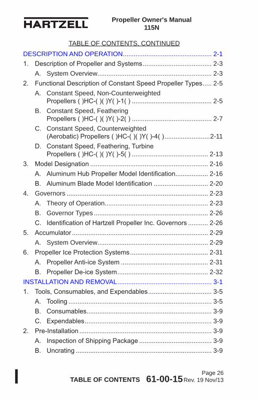
61-00-15 TABLE OF CONTENTSPage 25
Rev. 19 Nov/13
Propeller Owner's Manual 115N
MESSAGE ..........................................................................................1
REVISION HIGHLIGHTS ...................................................................5
RECORD OF REVISIONS .................................................................9
RECORD OF TEMPORARY REVISIONS ........................................11
SERVICE DOCUMENTS LIST .........................................................13
AIRWORTHINESS LIMITATIONS ....................................................15
LIST OF EFFECTIVE PAGES ..........................................................23
TABLE OF CONTENTS ....................................................................27
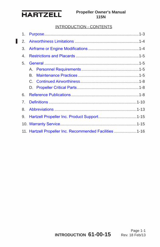
INTRODUCTION ............................................................................ 1-11. Purpose .................................................................................... 1-32. Airworthiness Limitations ......................................................... 1-43. AirframeorEngineModifications ............................................. 1-44. RestrictionsandPlacards ........................................................ 1-55. General .................................................................................... 1-5
A. PersonnelRequirements ................................................... 1-5B. MaintenancePractices ...................................................... 1-5C. Continued Airworthiness .................................................... 1-8D. PropellerCriticalParts ....................................................... 1-8
6. ReferencePublications ............................................................ 1-87. Definitions .............................................................................. 1-108. Abbreviations ......................................................................... 1-139. HartzellPropellerInc.ProductSupport .................................. 1-1510.WarrantyService .................................................................... 1-1511. HartzellPropellerInc.RecommendedFacilities .................... 1-16
TABLE OF CONTENTS
61-00-15 TABLE OF CONTENTSPage 26
Rev. 19 Nov/13
Propeller Owner's Manual 115N
DESCRIPTION AND OPERATION ................................................. 2-11. DescriptionofPropellerandSystems ...................................... 2-3
A. System Overview ............................................................... 2-32. FunctionalDescriptionofConstantSpeedPropellerTypes ..... 2-5
A. Constant Speed, Non-Counterweighted Propellers()HC-()()Y()-1() ............................................ 2-5B. Constant Speed, Feathering Propellers()HC-()()Y()-2() ............................................ 2-7C. Constant Speed, Counterweighted (Aerobatic)Propellers()HC-()()Y()-4() .........................2-11D. ConstantSpeed,Feathering,Turbine Propellers()HC-()()Y()-5() .......................................... 2-13
3. ModelDesignation ................................................................. 2-16A. AluminumHubPropellerModelIdentification .................. 2-16B. AluminumBladeModelIdentification .............................. 2-20
4. Governors .............................................................................. 2-23A. Theory of Operation ......................................................... 2-23B. Governor Types ............................................................... 2-26C. IdentificationofHartzellPropellerInc.Governors ........... 2-26
5. Accumulator ........................................................................... 2-29A. System Overview ............................................................. 2-29
6. PropellerIceProtectionSystems ........................................... 2-31A. PropellerAnti-iceSystem ................................................ 2-31B. PropellerDe-iceSystem .................................................. 2-32
INSTALLATION AND REMOVAL .................................................... 3-11. Tools,Consumables,andExpendables ................................... 3-5
A. Tooling ............................................................................... 3-5B. Consumables ..................................................................... 3-9C. Expendables ...................................................................... 3-9
2. Pre-Installation ......................................................................... 3-9A. InspectionofShippingPackage ........................................ 3-9B. Uncrating ........................................................................... 3-9
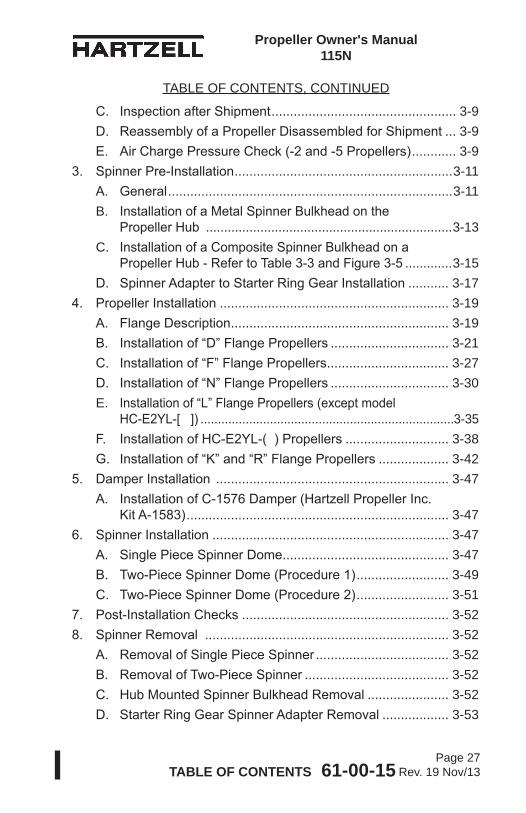
TABLE OF CONTENTS, CONTINUED
61-00-15 TABLE OF CONTENTSPage 27
Rev. 19 Nov/13
Propeller Owner's Manual 115N
C. InspectionafterShipment .................................................. 3-9D. ReassemblyofaPropellerDisassembledforShipment ... 3-9E. AirChargePressureCheck(-2and-5Propellers) ............ 3-9
3. SpinnerPre-Installation ...........................................................3-11A. General .............................................................................3-11B. InstallationofaMetalSpinnerBulkheadonthe PropellerHub ....................................................................3-13C. InstallationofaCompositeSpinnerBulkheadona PropellerHub-RefertoTable3-3andFigure3-5 .............3-15D. SpinnerAdaptertoStarterRingGearInstallation ........... 3-17
4. PropellerInstallation .............................................................. 3-19A. FlangeDescription ........................................................... 3-19B. Installationof“D”FlangePropellers ................................ 3-21C. Installationof“F”FlangePropellers ................................. 3-27D. Installationof“N”FlangePropellers ................................ 3-30E. Installationof“L”FlangePropellers(exceptmodel HC-E2YL-[]) .........................................................................3-35F. InstallationofHC-E2YL-()Propellers ............................ 3-38G. Installationof“K”and“R”FlangePropellers ................... 3-42
5. DamperInstallation ............................................................... 3-47A. InstallationofC-1576Damper(HartzellPropellerInc. KitA-1583) ....................................................................... 3-47
6. SpinnerInstallation ................................................................ 3-47A. SinglePieceSpinnerDome ............................................. 3-47B. Two-PieceSpinnerDome(Procedure1) ......................... 3-49C. Two-PieceSpinnerDome(Procedure2) ......................... 3-51
7. Post-InstallationChecks ........................................................ 3-528. SpinnerRemoval .................................................................. 3-52
A. RemovalofSinglePieceSpinner .................................... 3-52B. RemovalofTwo-PieceSpinner ....................................... 3-52C. HubMountedSpinnerBulkheadRemoval ...................... 3-52D. StarterRingGearSpinnerAdapterRemoval .................. 3-53
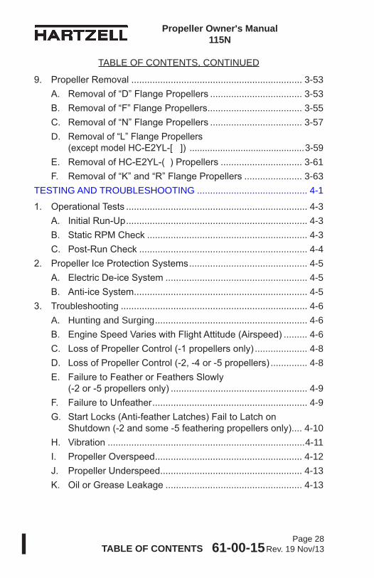
TABLE OF CONTENTS, CONTINUED
61-00-15 TABLE OF CONTENTSPage 28
Rev. 19 Nov/13
Propeller Owner's Manual 115N
9. PropellerRemoval ................................................................. 3-53A. Removalof“D”FlangePropellers ................................... 3-53B. Removalof“F”FlangePropellers .................................... 3-55C. Removalof“N”FlangePropellers ................................... 3-57D. Removalof“L”FlangePropellers (exceptmodelHC-E2YL-[]) .............................................3-59E. RemovalofHC-E2YL-()Propellers ............................... 3-61F. Removalof“K”and“R”FlangePropellers ...................... 3-63
TESTING AND TROUBLESHOOTING .......................................... 4-1
1. OperationalTests ..................................................................... 4-3A. InitialRun-Up ..................................................................... 4-3B. StaticRPMCheck ............................................................. 4-3C. Post-RunCheck ................................................................ 4-4
2. PropellerIceProtectionSystems ............................................. 4-5A. ElectricDe-iceSystem ...................................................... 4-5B. Anti-iceSystem .................................................................. 4-5
3. Troubleshooting ....................................................................... 4-6A. Hunting and Surging .......................................................... 4-6B. EngineSpeedVarieswithFlightAttitude(Airspeed) ......... 4-6C. LossofPropellerControl(-1propellersonly) .................... 4-8D. LossofPropellerControl(-2,-4or-5propellers) .............. 4-8E. FailuretoFeatherorFeathersSlowly (-2or-5propellersonly) .................................................... 4-9F. FailuretoUnfeather ........................................................... 4-9G. StartLocks(Anti-featherLatches)FailtoLatchon Shutdown(-2andsome-5featheringpropellersonly) .... 4-10H. Vibration ...........................................................................4-11I. PropellerOverspeed ........................................................ 4-12J. PropellerUnderspeed ...................................................... 4-13K. OilorGreaseLeakage .................................................... 4-13
TABLE OF CONTENTS, CONTINUED
61-00-15 TABLE OF CONTENTSPage 29
Rev. 19 Nov/13
Propeller Owner's Manual 115N
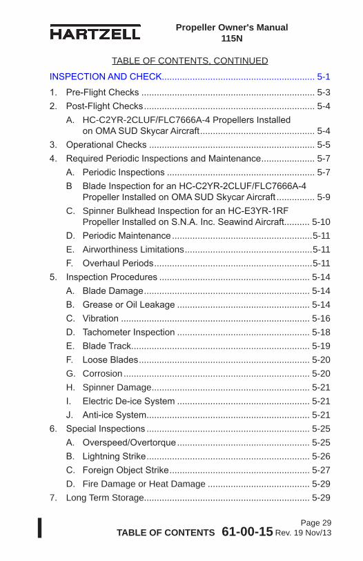
INSPECTIONANDCHECK ............................................................ 5-1
1. Pre-FlightChecks .................................................................... 5-32. Post-FlightChecks ................................................................... 5-4
A. HC-C2YR-2CLUF/FLC7666A-4 PropellersInstalled onOMASUDSkycarAircraft ............................................. 5-4
3. OperationalChecks ................................................................. 5-54. RequiredPeriodicInspectionsandMaintenance ..................... 5-7
A. PeriodicInspections .......................................................... 5-7B BladeInspectionforanHC-C2YR-2CLUF/FLC7666A-4 PropellerInstalledonOMASUDSkycarAircraft ............... 5-9C. Spinner BulkheadInspectionforanHC-E3YR-1RF PropellerInstalledonS.N.A.Inc.SeawindAircraft. ......... 5-10D. PeriodicMaintenance .......................................................5-11E. Airworthiness Limitations ..................................................5-11F. OverhaulPeriods ..............................................................5-11
5. InspectionProcedures ........................................................... 5-14A. BladeDamage ................................................................. 5-14B. GreaseorOilLeakage .................................................... 5-14C. Vibration .......................................................................... 5-16D. TachometerInspection .................................................... 5-18E. BladeTrack ...................................................................... 5-19F. LooseBlades ................................................................... 5-20G. Corrosion ......................................................................... 5-20H. Spinner Damage .............................................................. 5-21I. ElectricDe-iceSystem .................................................... 5-21J. Anti-iceSystem ................................................................ 5-21
6. SpecialInspections ................................................................ 5-25A. Overspeed/Overtorque .................................................... 5-25B. LightningStrike ................................................................ 5-26C. ForeignObjectStrike ....................................................... 5-27D. Fire Damage or Heat Damage ........................................ 5-29
7. Long Term Storage................................................................. 5-29
TABLE OF CONTENTS, CONTINUED
61-00-15 TABLE OF CONTENTSPage 30
Rev. 19 Nov/13
Propeller Owner's Manual 115N
MAINTENANCE PRACTICES ........................................................ 6-1
1. Cleaning ................................................................................... 6-3A. GeneralCleaning ............................................................... 6-3B. SpinnerCleaningandPolishing ........................................ 6-5
2. Lubrication ............................................................................... 6-5A. LubricationIntervals .......................................................... 6-5B. LubricationProcedure ....................................................... 6-7C. ApprovedLubricants ........................................................ 6-10
3. AirCharge(-2and-5Propellers) ............................................6-11A. ChargingthePropeller ......................................................6-11B. Basicpressures ............................................................... 6-13
4. UnfeatheringAccumulatorAirCharge ................................... 6-19A. ChargingaHartzellPropellerInc.Accumulator ............... 6-19
5. BladeRepairs ........................................................................ 6-21A. RepairofNicksorGouges .............................................. 6-21B. RepairofBentBlades ...................................................... 6-24
6. Painting After Repair .............................................................. 6-25A. General ............................................................................ 6-25B. PaintingofAluminumBlades ........................................... 6-26
7. DynamicBalance ................................................................... 6-29A. Overview .......................................................................... 6-29B. InspectionProceduresBeforeBalancing ........................ 6-30C. ModifyingSpinnerBulkheadtoAccommodate DynamicBalanceWeights ............................................... 6-31D. PlacementofBalanceWeightsforDynamicBalance ..... 6-32
8. PropellerLowPitchSetting .................................................... 6-33A. LowPitchStop-AllPropellerModels ............................. 6-33B. Max.RPM(Static)LowPitchStopAdjustment ................ 6-35
9. PropellerHighPitchSettings ................................................. 6-37A. HighPitch(Min.RPM)StoporFeatheringPitchStop ..... 6-37
10.StartLockSettings ................................................................. 6-37A. StartLockPitchStop ....................................................... 6-37
TABLE OF CONTENTS, CONTINUED
61-00-15 TABLE OF CONTENTSPage 31
Rev. 19 Nov/13
Propeller Owner's Manual 115N
11. PropellerIceProtectionSystems ........................................... 6-37A. ElectricDe-iceSystem .................................................... 6-37B. Anti-iceSystem ................................................................ 6-37
ANTI-ICE AND DE-ICE SYSTEMS ................................................ 7-11. Introduction .............................................................................. 7-3
A. PropellerDe-iceSystem .................................................... 7-3B. PropellerAnti-iceSystem .................................................. 7-3
2. SystemDescription .................................................................. 7-4A. De-iceSystem ................................................................... 7-4B. Anti-iceSystem .................................................................. 7-5
3. De-iceSystemFunctionalTests ............................................... 7-64. Anti-iceSystemFunctionalTests ............................................. 7-65. De-iceandAnti-iceSystemInspections ................................... 7-7
A. De-iceSystemInspections ................................................ 7-7B. Anti-iceSystemInspections .............................................. 7-7
6. De-iceandAnti-iceSystemTroubleshooting ........................... 7-8A. De-iceSystemTroubleshooting ......................................... 7-8B. Anti-iceSystemTroubleshooting ....................................... 7-8
RECORDS ..................................................................................... 8-1
1. Introduction .............................................................................. 8-32. RecordKeeping ....................................................................... 8-3
A. InformationtobeRecorded ............................................... 8-3
61-00-15 TABLE OF CONTENTSPage 32
Rev. 19 Nov/13
Propeller Owner's Manual 115N
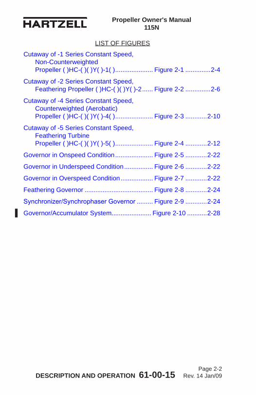
LIST OF FIGURES
Cutaway of -1 Series Constant Speed Non-CounterweightedPropeller ()HC-()()Y()-1() ...................................... Figure 2-1 ............ 2-4
Cutaway of -2 Series Constant Speed FeatheringPropeller()HC-()()Y()-2 ......... Figure 2-2 ............ 2-6
Cutaway of -4 Series Constant Speed, Counterweighted(Aerobatic) Propeller()HC-()()Y()-4() ....................... Figure 2-3 .......... 2-10
Cutaway of -5 Series Constant Speed, FeatheringTurbinePropeller ()HC-()()Y()-5() ...................................... Figure 2-4 .......... 2-12
Governor in Onspeed Condition ....................... Figure 2-5 .......... 2-22
Governor in Underspeed Condition .................. Figure 2-6 .......... 2-22
Governor in Overspeed Condition .................... Figure 2-7 .......... 2-22
Feathering Governor ........................................ Figure 2-8 .......... 2-24
Synchronizer/SynchrophaserGovernor ........... Figure 2-9 .......... 2-24
Governor/AccumulatorSystem......................... Figure 2-10 ........ 2-28
DeterminingTorqueValueWhenUsing TorquingAdapter ........................................ Figure 3-1 ............ 3-6
DiagramofTorquingSequence forPropellerMountingHardware .............. Figure 3-2 ............ 3-8
HubClampingBoltLocation ............................. Figure 3-3 .......... 3-10
MetalBulkheadandSpinnerMounting (HubMountedSpinner) .............................. Figure 3-4 .......... 3-12
CompositeBulkheadandSpinnerMounting (HubMountedSpinner) .............................. Figure 3-5 .......... 3-14
Spinner Adapter and Spinner Mounting (StarterRingGearMount) ......................... Figure 3-6 .......... 3-16
“D”FlangePropellerMounting ......................... Figure 3-7 .......... 3-20
“F”and“N”FlangePropellerMounting ............. Figure 3-8 .......... 3-26
61-00-15 TABLE OF CONTENTSPage 33
Rev. 19 Nov/13
Propeller Owner's Manual 115N
“L”,“K”,and“R”FlangePropellerMounting ..... Figure 3-9 .......... 3-34
DamperInstallation...........................................Figure 3-10 ........ 3-46
TwoPieceSpinnerMounting(Procedure1) ..... Figure 3-11 ........ 3-48
TwoPieceSpinnerMounting(Procedure2) ..... Figure 3-12 ........ 3-50
SpinnerDometoBulkheadMounting HoleAlignment ...........................................Figure 3-13 ........ 3-50
CheckingBladeTrack....................................... Figure 5-1 ......... 5-18
BladePlay ........................................................Figure 5-2 .......... 5-18
ReciprocatingEngineOverspeedLimits .......... Figure 5-3 .......... 5-22
TurbineEngineOverspeedLimits .................... Figure 5-4 .......... 5-23
TurbineEngineOvertorqueLimits .................... Figure 5-5 .......... 5-24
LubricationFittingandAirCharge ValveLocation ............................................Figure 6-1 ............ 6-4
LubricationFitting .............................................Figure 6-2 ............ 6-6
LubricationLabel ..............................................Figure 6-3 ............ 6-8
Counterweighted vs Non-Counterweighted Blades ........................................................Figure 6-4 .......... 6-12
UnfeatheringAccumulator ................................ Figure 6-5 .......... 6-18
Repair Limitations .............................................Figure 6-6 .......... 6-22
LowPitchStopAdjustment(-1,-4) ................... Figure 6-7 .......... 6-34
LowPitchStopAdjustment(-2,-5) ................... Figure 6-8 .......... 6-34
LIST OF FIGURES, CONTINUED
61-00-15 TABLE OF CONTENTSPage 34
Rev. 19 Nov/13
Propeller Owner's Manual 115N
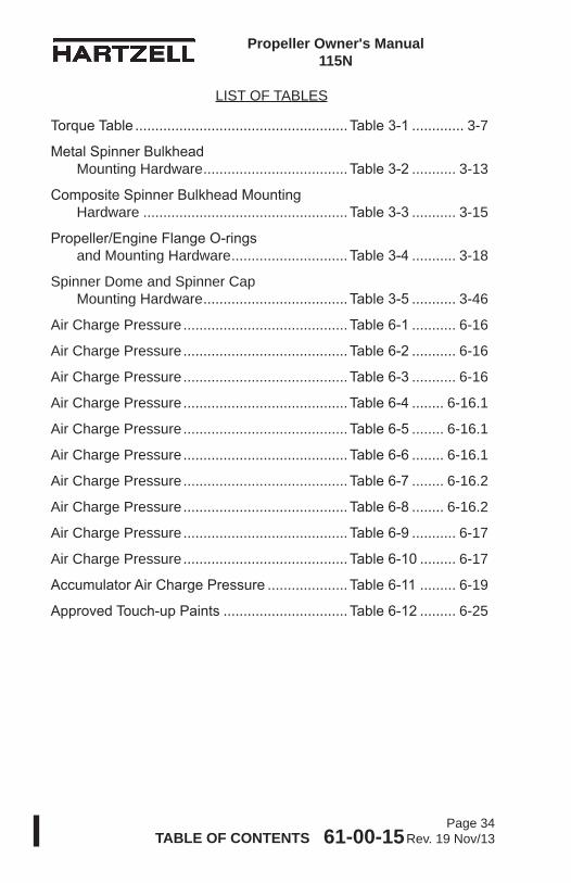
LIST OF TABLES
TorqueTable .....................................................Table3-1 ............. 3-7
MetalSpinnerBulkhead Mounting Hardware ....................................Table3-2 ........... 3-13
CompositeSpinnerBulkheadMounting Hardware ...................................................Table3-3 ........... 3-15
Propeller/EngineFlangeO-rings and Mounting Hardware .............................Table3-4 ........... 3-18
Spinner Dome and Spinner Cap Mounting Hardware ....................................Table3-5 ........... 3-46
Air Charge Pressure .........................................Table6-1 ........... 6-16
Air Charge Pressure .........................................Table6-2 ........... 6-16
Air Charge Pressure .........................................Table6-3 ........... 6-16
Air Charge Pressure .........................................Table6-4 ........ 6-16.1
Air Charge Pressure .........................................Table6-5 ........ 6-16.1
Air Charge Pressure .........................................Table6-6 ........ 6-16.1
Air Charge Pressure .........................................Table6-7 ........ 6-16.2
Air Charge Pressure .........................................Table6-8 ........ 6-16.2
Air Charge Pressure .........................................Table6-9 ........... 6-17
Air Charge Pressure .........................................Table6-10 ......... 6-17
AccumulatorAirChargePressure ....................Table6-11 ......... 6-19
ApprovedTouch-upPaints ...............................Table6-12 ......... 6-25
Propeller Owner's Manual 115N
INTRODUCTION 61-00-15 Page 1-1
Rev. 18 Feb/13
INTRODUCTION - CONTENTS
1. Purpose ....................................................................................1-3
2. Airworthiness Limitations .........................................................1-4
3. Airframe or Engine Modifications .............................................1-4
4. Restrictions and Placards ........................................................1-5
5. General ....................................................................................1-5A. Personnel Requirements ...................................................1-5B. Maintenance Practices ......................................................1-5C. Continued Airworthiness ....................................................1-8D. Propeller Critical Parts .......................................................1-8
6. Reference Publications ............................................................1-8
7. Definitions ..............................................................................1-10
8. Abbreviations .........................................................................1-13
9. Hartzell Propeller Inc. Product Support ..................................1-15
10. Warranty Service ....................................................................1-15
11. Hartzell Propeller Inc. Recommended Facilities ....................1-16

Propeller Owner's Manual 115N
INTRODUCTION 61-00-15 Page 1-2
Rev. 18 Feb/13
(This page is intentionally blank.)
Propeller Owner's Manual 115N
INTRODUCTION 61-00-15 Page 1-3
Rev. 18 Feb/13
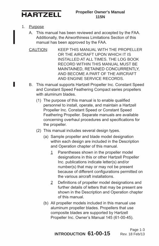
1. PurposeA. This manual has been reviewed and accepted by the FAA.
Additionally, the Airworthiness Limitations Section of this manual has been approved by the FAA.
CAUTION: KEEP THIS MANUAL WITH THE PROPELLER OR THE AIRCRAFT UPON WHICH IT IS INSTALLED AT ALL TIMES. THE LOG BOOK RECORD WITHIN THIS MANUAL MUST BE MAINTAINED, RETAINED CONCURRENTLY, AND BECOME A PART OF THE AIRCRAFT AND ENGINE SERVICE RECORDS.
B. This manual supports Hartzell Propeller Inc. Constant Speed and Constant Speed Feathering Compact series propellers with aluminum blades.(1) The purpose of this manual is to enable qualified
personnel to install, operate, and maintain a Hartzell Propeller Inc. Constant Speed or Constant Speed Feathering Propeller. Separate manuals are available concerning overhaul procedures and specifications for the propeller.
(2) This manual includes several design types. (a) Sample propeller and blade model designation
within each design are included in the Description and Operation chapter of this manual.1 Parentheses shown in the propeller model
designations in this or other Hartzell Propeller Inc. publications indicate letter(s) and/or number(s) that may or may not be present because of different configurations permitted on the various aircraft installations.
2 Definitions of propeller model designations and further details of letters that may be present are shown in the Description and Operation chapter of this manual.
(b) All propeller models included in this manual use aluminum propeller blades. Propellers that use composite blades are supported by Hartzell Propeller Inc. Owner’s Manual 145 (61-00-45).
Propeller Owner's Manual 115N
INTRODUCTION 61-00-15 Page 1-4
Rev. 18 Feb/13
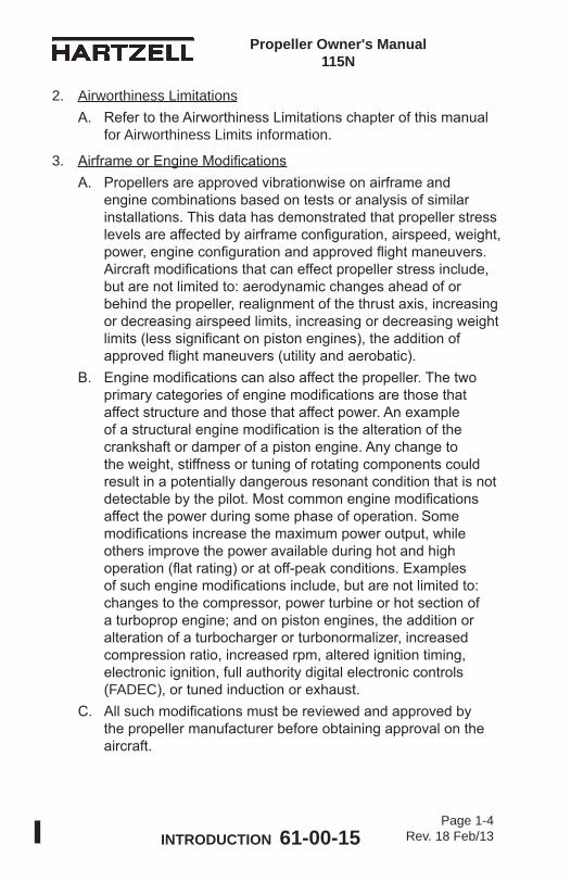
2. Airworthiness LimitationsA. Refer to the Airworthiness Limitations chapter of this manual
for Airworthiness Limits information.
3. Airframe or Engine ModificationsA. Propellers are approved vibrationwise on airframe and
engine combinations based on tests or analysis of similar installations. This data has demonstrated that propeller stress levels are affected by airframe configuration, airspeed, weight, power, engine configuration and approved flight maneuvers. Aircraft modifications that can effect propeller stress include, but are not limited to: aerodynamic changes ahead of or behind the propeller, realignment of the thrust axis, increasing or decreasing airspeed limits, increasing or decreasing weight limits (less significant on piston engines), the addition of approved flight maneuvers (utility and aerobatic).
B. Engine modifications can also affect the propeller. The two primary categories of engine modifications are those that affect structure and those that affect power. An example of a structural engine modification is the alteration of the crankshaft or damper of a piston engine. Any change to the weight, stiffness or tuning of rotating components could result in a potentially dangerous resonant condition that is not detectable by the pilot. Most common engine modifications affect the power during some phase of operation. Some modifications increase the maximum power output, while others improve the power available during hot and high operation (flat rating) or at off-peak conditions. Examples of such engine modifications include, but are not limited to: changes to the compressor, power turbine or hot section of a turboprop engine; and on piston engines, the addition or alteration of a turbocharger or turbonormalizer, increased compression ratio, increased rpm, altered ignition timing, electronic ignition, full authority digital electronic controls (FADEC), or tuned induction or exhaust.
C. All such modifications must be reviewed and approved by the propeller manufacturer before obtaining approval on the aircraft.
Propeller Owner's Manual 115N
INTRODUCTION 61-00-15 Page 1-5
Rev. 17 Jul/12
4. Restrictions and PlacardsA. The propellers included in this manual may have a restricted
operating range that requires a cockpit placard. (1) The restrictions, if present, will vary depending on the
propeller, blade, engine, and/or aircraft model. (2) Review the propeller and aircraft type certificate data
sheet (TCDS), Pilot Operating Handbook (POH), and any applicable Airworthiness Directives for specific information.
5. GeneralA. Personnel Requirements
(1) Personnel performing maintenance are expected to have sufficient training and certifications (when required by the applicable Aviation Authority) to accomplish the work required in a safe and airworthy manner.
(2) Compliance to the applicable regulatory requirements established by the Federal Aviation Administration (FAA) or foreign equivalent is mandatory for anyone performing or accepting responsibility for any inspection and/or repair and/or overhaul of any Hartzell Propeller Inc. product.
B. Maintenance Practices(1) The propeller and its components are highly vulnerable
to damage while they are removed from the engine. Properly protect all components until they are reinstalled on the engine.
(2) Never attempt to move the aircraft by pulling on the propeller.
(3) Avoid the use of blade paddles. If blade paddles must be used, use at least two paddles. Do not put the blade paddle in the area of the de-ice or anti-icing boot when applying torque to a blade assembly. Put the blade paddle in the thickest area of the blade, just outside of the de-ice or anti-icing boot. Use one blade paddle per blade.
(4) Use only the approved consumables, e.g., cleaning agents, lubricants, etc.
Propeller Owner's Manual 115N
INTRODUCTION 61-00-15 Page 1-6
Rev. 17 Jul/12
(5) Safe Handling of Paints and Chemicals(a) Always use caution when handling or being exposed
to paints and/or chemicals during propeller overhaul and maintenance procedures.
(b) Before using paint or chemicals, always read the manufacturer’s label on the container and follow specified instructions and procedures for storage, preparation, mixing, and application.
(c) Refer to the product’s Material Safety Data Sheet (MSDS) for detailed information about physical properties, health, and physical hazards of any chemical.
(6) Observe applicable torque values during maintenance.(7) Approved corrosion protection followed by approved paint
must be applied to all aluminum blades. For information concerning the application of corrosion protection and paint, refer to the Maintenance Practices chapter of this manual. Operation of blades without the specified coatings and finishes, i.e., “polished blades”, is not permitted.
(8) Before installing the propeller on the engine, the propeller must be statically balanced. New propellers are statically balanced at Hartzell Propeller Inc.. Overhauled propellers must be statically balanced by the overhaul facility before return to service.(a) Dynamic balance is recommended, but may be
accomplished at the discretion of the operator, unless specifically required by the airframe or engine manufacturer. 1 Perform dynamic balance in accordance with the
Maintenance Practices chapter of this manual. 2 Additional procedures may be found in the
aircraft maintenance manual.(9) As necessary, use a soft, non-graphite pencil or crayon
to make identifying marks on components.(10) As applicable, follow military standard NASM33540 for
safety-wiring and cotter pinning general practices. Use 0.032 (0.81 mm) safety wire unless otherwise indicated.

Propeller Owner's Manual 115N
INTRODUCTION 61-00-15 Page 1-7
Rev. 17 Jul/12
CAUTION: DO NOT USE OBSOLETE OR OUTDATED INFORMATION. PERFORM ALL INSPECTIONS OR WORK IN ACCORDANCE WITH THE MOST RECENT REVISION OF THIS MANUAL. INFORMATION CONTAINED IN THIS MANUAL MAY BE SIGNIFICANTLY CHANGED FROM EARLIER REVISIONS. USE OF OBSOLETE INFORMATION MAY RESULT IN DEATH, SERIOUS BODILY INJURY, AND/OR SUBSTANTIAL PROPERTY DAMAGE. FOR THE MOST RECENT REVISION LEVEL OF THIS MANUAL, REFER TO THE HARTZELL PROPELLER INC. WEBSITE AT WWW.HARTZELLPROP.COM.
(11) The information in this manual revision supersedes data in all previously published revisions of this manual.
(12) Refer to the airframe manufacturer’s manuals in addition to the information in this manual because of possible special requirements for specific aircraft applications.
(13) If the propeller is equipped with an ice protection system that uses components supplied by Hartzell Propeller Inc., applicable instructions and technical information for the components supplied by Hartzell Propeller Inc. can be found in the following publications available on the Hartzell Propeller Inc. website at www.hartzellprop.com:(a) Manual 180 (30-61-80) - Propeller Ice Protection
System Manual (b) Manual 181 (30-60-81) - Propeller Ice Protection
System Component Maintenance Manual(c) Manual 182 (61-12-82) - Propeller Electrical De-Ice
Boot Removal and Installation Manual(d) Manual 183 (61-12-83) - Propeller Anti-Icing Boot
Removal and Installation Manual(14) Propeller ice protection system components not
supplied by Hartzell Propeller Inc. are controlled by the applicable TC or STC holder’s Instructions for Continued Airworthiness (ICA).
Propeller Owner's Manual 115N
INTRODUCTION 61-00-15 Page 1-8
Rev. 17 Jul/12
C. Continued Airworthiness(1) Operators are urged to stay informed of Airworthiness
information using Hartzell Propeller Inc. Service Bulletins and Service Letters that are available from Hartzell Propeller Inc. distributors, or from the Hartzell Propeller Inc. factory by subscription. Selected information is also available on the Hartzell Propeller Inc. website at www.hartzellprop.com.
D. Propeller Critical Parts(1) The following maintenance procedures may involve
propeller critical parts. These procedures have been substantiated based on Engineering analysis that expects this product will be operated and maintained using the procedures and inspections provided in the Instructions for Continued Airworthiness (ICA) for this product. Refer to the Illustrated Parts List chapter of the applicable maintenance manual for the applicable propeller model for the identification of specific Propeller Critical Parts.
(2) Numerous propeller system parts can produce a propeller Major or Hazardous effect, even though those parts may not be considered as Propeller Critical Parts. The operating and maintenance procedures and inspections provided in the ICA for this product are, therefore, expected to be accomplished for all propeller system parts.
6. Reference PublicationsThe following publications are referenced within this manual:Active Hartzell Propeller Inc. Service Bulletins, Service Letters, Service Instructions, and Service Advisories.Hartzell Propeller Inc. Manual No. 113B (61-10-13) - Compact Non-Feathering (-1) and Aerobatic (-4) Propeller Overhaul and Maintenance ManualHartzell Propeller Inc. Manual No. 117D (61-10-17) - Compact Constant Speed and Feathering Propeller Overhaul and Maintenance ManualHartzell Propeller Inc. Manual No. 127 (61-16-27) - Metal Spinner Assembly Maintenance
Propeller Owner's Manual 115N
INTRODUCTION 61-00-15 Page 1-9
Rev. 17 Jul/12
Hartzell Propeller Inc. Manual No. 130B (61-23-30) - Governor Overhaul ManualHartzell Propeller Inc. Manual No. 133C (61-13-33) - Aluminum Blade OverhaulHartzell Propeller Inc. Manual No. 148 (61-16-48) - Composite Spinner MaintenanceHartzell Propeller Inc. Manual No. 159 (61-02-59) - Application Guide - Also available on the Hartzell Propeller Inc. website at www.hartzellprop.comHartzell Propeller Inc. Manual No. 165A (61-00-65) - Illustrated Tool and Equipment ManualHartzell Propeller Inc. Manual No. 180 (30-61-80) - Propeller Ice Protection System Manual - Also available on the Hartzell Propeller Inc. website at www.hartzellprop.comHartzell Propeller Inc. Manual No. 181 (30-60-81) - Propeller Ice Protection System Component Maintenance Manual - Also available on the Hartzell Propeller Inc. website at www.hartzellprop.com
Hartzell Propeller Inc. Manual No. 182 (61-12-82) - Propeller Electrical De-ice Boot Removal and Installation Manual - Also available on the Hartzell Propeller Inc. website at www.hartzellprop.com
Hartzell Propeller Inc. Manual No. 183 (61-12-83) - Propeller Anti-icing Boot Removal and Installation Manual - Also available on the Hartzell Propeller Inc. website at www.hartzellprop.comHartzell Propeller Inc. Manual No. 202A (61-01-02) - Standard Practices Manual, Volumes 1 through 11Hartzell Propeller Inc. Service Letter HC-SL-61-61Y - Overhaul Periods and Service Life Limits for Hartzell Propellers, Governors, and Propeller Damper Assemblies - Also available on the Hartzell Propeller Inc. website at www.hartzellprop.com
Propeller Owner's Manual 115N
INTRODUCTION 61-00-15 Page 1-10
Rev. 17 Jul/12
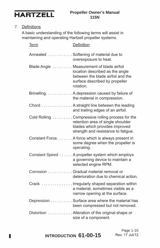
7. DefinitionsA basic understanding of the following terms will assist in maintaining and operating Hartzell propeller systems.
Term Definition
Annealed . . . . . . . . . . . Softening of material due to overexposure to heat.
Blade Angle . . . . . . . . . Measurement of blade airfoil location described as the angle between the blade airfoil and the surface described by propeller rotation.
Brinelling . . . . . . . . . . . . A depression caused by failure of the material in compression.
Chord . . . . . . . . . . . . . . A straight line between the leading and trailing edges of an airfoil.
Cold Rolling . . . . . . . . . Compressive rolling process for the retention area of single shoulder blades which provides improved strength and resistance to fatigue.
Constant Force . . . . . . . A force which is always present in some degree when the propeller is operating.
Constant Speed . . . . . . A propeller system which employs a governing device to maintain a selected engine RPM.
Corrosion . . . . . . . . . . . Gradual material removal or deterioration due to chemical action.
Crack . . . . . . . . . . . . . . Irregularly shaped separation within a material, sometimes visible as a narrow opening at the surface.
Depression . . . . . . . . . . Surface area where the material has been compressed but not removed.
Distortion . . . . . . . . . . . Alteration of the original shape or size of a component.
Propeller Owner's Manual 115N
INTRODUCTION 61-00-15 Page 1-11
Rev. 17 Jul/12
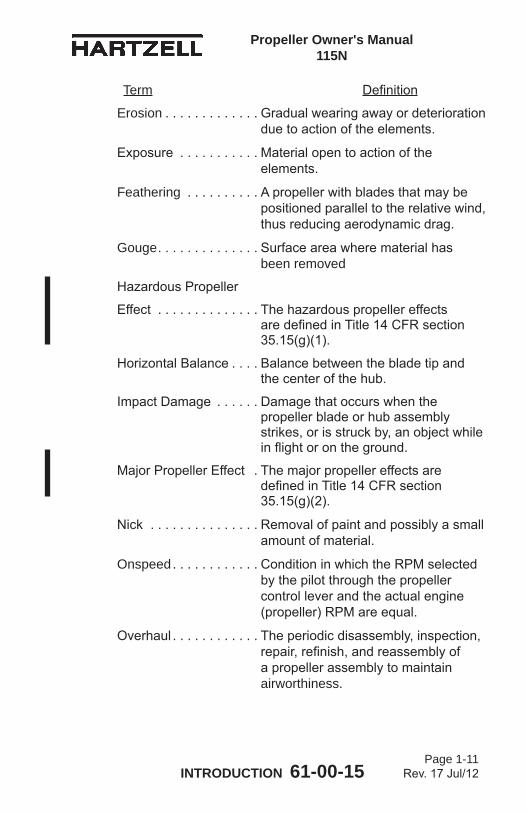
Erosion . . . . . . . . . . . . . Gradual wearing away or deterioration due to action of the elements.
Exposure . . . . . . . . . . . Material open to action of the elements.
Feathering . . . . . . . . . . A propeller with blades that may be positioned parallel to the relative wind, thus reducing aerodynamic drag.
Gouge . . . . . . . . . . . . . . Surface area where material has been removed
Hazardous Propeller
Effect . . . . . . . . . . . . . . The hazardous propeller effects are defined in Title 14 CFR section 35.15(g)(1).
Horizontal Balance . . . . Balance between the blade tip and the center of the hub.
Impact Damage . . . . . . Damage that occurs when the propeller blade or hub assembly strikes, or is struck by, an object while in flight or on the ground.
Major Propeller Effect . The major propeller effects are defined in Title 14 CFR section 35.15(g)(2).
Nick . . . . . . . . . . . . . . . Removal of paint and possibly a small amount of material.
Onspeed . . . . . . . . . . . . Condition in which the RPM selected by the pilot through the propeller control lever and the actual engine (propeller) RPM are equal.
Overhaul . . . . . . . . . . . . The periodic disassembly, inspection, repair, refinish, and reassembly of a propeller assembly to maintain airworthiness.
Term Definition
Propeller Owner's Manual 115N
INTRODUCTION 61-00-15 Page 1-12
Rev. 17 Jul/12
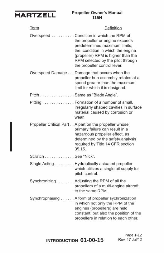
Overspeed . . . . . . . . . . Condition in which the RPM of the propeller or engine exceeds predetermined maximum limits; the condition in which the engine (propeller) RPM is higher than the RPM selected by the pilot through the propeller control lever.
Overspeed Damage . . . Damage that occurs when the propeller hub assembly rotates at a speed greater than the maximum limit for which it is designed.
Pitch . . . . . . . . . . . . . . . Same as “Blade Angle”.
Pitting . . . . . . . . . . . . . . Formation of a number of small, irregularly shaped cavities in surface material caused by corrosion or wear.
Propeller Critical Part . . A part on the propeller whose primary failure can result in a hazardous propeller effect, as determined by the safety analysis required by Title 14 CFR section 35.15.
Scratch . . . . . . . . . . . . . See “Nick”.
Single Acting . . . . . . . . . Hydraulically actuated propeller which utilizes a single oil supply for pitch control.
Synchronizing . . . . . . . . Adjusting the RPM of all the propellers of a multi-engine aircraft to the same RPM.
Synchrophasing . . . . . . A form of propeller sychronization in which not only the RPM of the engines (propellers) are held constant, but also the position of the propellers in relation to each other.
Term Definition
Propeller Owner's Manual 115N
INTRODUCTION 61-00-15 Page 1-13
Rev. 17 Jul/12
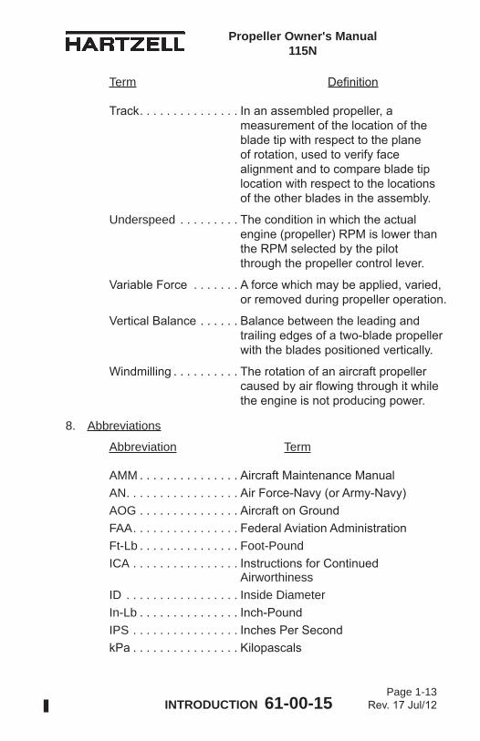
Track . . . . . . . . . . . . . . . In an assembled propeller, a measurement of the location of the blade tip with respect to the plane of rotation, used to verify face alignment and to compare blade tip location with respect to the locations of the other blades in the assembly.
Underspeed . . . . . . . . . The condition in which the actual engine (propeller) RPM is lower than the RPM selected by the pilot through the propeller control lever.
Variable Force . . . . . . . A force which may be applied, varied, or removed during propeller operation.
Vertical Balance . . . . . . Balance between the leading and trailing edges of a two-blade propeller with the blades positioned vertically.
Windmilling . . . . . . . . . . The rotation of an aircraft propeller caused by air flowing through it while the engine is not producing power.
8. Abbreviations
Abbreviation Term
AMM . . . . . . . . . . . . . . . Aircraft Maintenance ManualAN . . . . . . . . . . . . . . . . . Air Force-Navy (or Army-Navy)AOG . . . . . . . . . . . . . . . Aircraft on GroundFAA . . . . . . . . . . . . . . . . Federal Aviation AdministrationFt-Lb . . . . . . . . . . . . . . . Foot-PoundICA . . . . . . . . . . . . . . . . Instructions for Continued
AirworthinessID . . . . . . . . . . . . . . . . . Inside DiameterIn-Lb . . . . . . . . . . . . . . . Inch-PoundIPS . . . . . . . . . . . . . . . . Inches Per SecondkPa . . . . . . . . . . . . . . . . Kilopascals
Term Definition
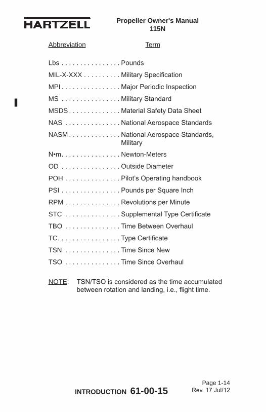
Propeller Owner's Manual 115N
INTRODUCTION 61-00-15 Page 1-14
Rev. 17 Jul/12
Lbs . . . . . . . . . . . . . . . . Pounds
MIL-X-XXX . . . . . . . . . . Military Specification
MPI . . . . . . . . . . . . . . . . Major Periodic Inspection
MS . . . . . . . . . . . . . . . . Military Standard
MSDS . . . . . . . . . . . . . . Material Safety Data Sheet
NAS . . . . . . . . . . . . . . . National Aerospace Standards
NASM . . . . . . . . . . . . . . National Aerospace Standards, Military
N•m . . . . . . . . . . . . . . . . Newton-Meters
OD . . . . . . . . . . . . . . . . Outside Diameter
POH . . . . . . . . . . . . . . . Pilot’s Operating handbook
PSI . . . . . . . . . . . . . . . . Pounds per Square Inch
RPM . . . . . . . . . . . . . . . Revolutions per Minute
STC . . . . . . . . . . . . . . . Supplemental Type Certificate
TBO . . . . . . . . . . . . . . . Time Between Overhaul
TC . . . . . . . . . . . . . . . . . Type Certificate
TSN . . . . . . . . . . . . . . . Time Since New
TSO . . . . . . . . . . . . . . . Time Since Overhaul
NOTE: TSN/TSO is considered as the time accumulated between rotation and landing, i.e., flight time.
Abbreviation Term
Propeller Owner's Manual 115N
INTRODUCTION 61-00-15 Page 1-15
Rev. 17 Jul/12
9. Hartzell Propeller Inc. Product SupportHartzell Propeller is ready to assist you with questions concerning your propeller system. Hartzell Propeller Inc. Product Support may be reached during business hours (8:00 am through 5:00 pm, United States Eastern Time) at (937) 778-4379 or at (800) 942-7767, toll free from the United States and Canada. Hartzell Propeller Inc. Product Support can also be reached by fax at (937) 778-4391, and by e-mail at [email protected] business hours, you may leave a message on our 24 hour product support line at (937) 778-4376 or at (800) 942-7767, toll free from the United States and Canada. A technical representative will contact you during normal business hours. Urgent AOG support is also available 24 hours per day, seven days per week via this message service.Additional information is available on our website at www.hartzellprop.com.NOTE: When calling from outside the United States, dial (001)
before dialing the above telephone numbers.
10. Warranty ServiceIf you believe you have a warranty claim, it is necessary to contact Hartzell’s Warranty Administrator. Hartzell’s Warranty Administrator will provide a blank Warranty Application form. It is necessary to complete this form and return it to the Warranty Administrator for evaluation before proceeding with repair or inspection work. Upon receipt of this form, the Warranty Administrator will provide instructions on how to proceed. Hartzell Propeller Inc. Warranty may be reached during business hours (8:00 am. through 5:00 pm., United States Eastern Time) at (937) 778-4379, or toll free from the United States and Canada at (800) 942-7767. Hartzell Propeller Inc. Warranty Administration can also be reached by fax, at (937) 778-4391, or by e-mail at [email protected]: When calling from outside the United States, dial (001)
before dialing the above telephone numbers.
Propeller Owner's Manual 115N
INTRODUCTION 61-00-15 Page 1-16
Rev. 17 Jul/12
11. Hartzell Propeller Inc. Recommended FacilitiesA. Hartzell Propeller Inc. recommends using Hartzell approved
distributors and repair facilities for the purchase, repair and overhaul of Hartzell Propeller Inc. propeller assemblies or components.
B. Information about the Hartzell Propeller Inc. worldwide network of aftermarket distributors and approved repair facilites is available on the Hartzell Propeller Inc. website at www.hartzellprop.com.
Propeller Owner's Manual 115N
DESCRIPTION AND OPERATION 61-00-15 Page 2-1
Rev. 17 Jul/12
DESCRIPTION AND OPERATION - CONTENTS
1. Description of Propeller and Systems ........................................2-3A. System Overview ...............................................................2-3
2. Functional Description of Constant Speed Propeller Types .......2-5A. Constant Speed, Non-Counterweighted
Propellers ( )HC-( )( )Y( )-1( ) ............................................2-5B. Constant Speed, Feathering
Propellers ( )HC-( )( )Y( )-2( ) ............................................2-7C. Constant Speed, Counterweighted
(Aerobatic) Propellers ( )HC-( )( )Y( )-4( ) ........................ 2-11D. Constant Speed, Feathering, Turbine
Propellers ( )HC-( )( )Y( )-5( ) ..........................................2-13
3. Model Designation ...................................................................2-16A. AluminumHubPropellerModelIdentification ..................2-16B. AluminumBladeModelIdentification ..............................2-20
4. Governors ................................................................................2-23A. Theory of Operation .........................................................2-23B. Governor Types ...............................................................2-26C. IdentificationofHartzellPropellerInc.Governors ...........2-26
5. Accumulator .............................................................................2-29A. System Overview .............................................................2-29
6. Propeller Ice Protection Systems .............................................2-31A. Propeller Anti-ice System ................................................2-31B. Propeller De-ice System ..................................................2-32
Propeller Owner's Manual 115N
DESCRIPTION AND OPERATION 61-00-15 Page 2-2
Rev. 14 Jan/09
LIST OF FIGURES
Cutaway of -1 Series Constant Speed, Non-Counterweighted Propeller ( )HC-( )( )Y( )-1( ) ..................... Figure 2-1 ..............2-4
Cutaway of -2 Series Constant Speed, Feathering Propeller ( )HC-( )( )Y( )-2 ...... Figure 2-2 ..............2-6
Cutaway of -4 Series Constant Speed, Counterweighted (Aerobatic) Propeller ( )HC-( )( )Y( )-4( ) ..................... Figure 2-3 ............2-10
Cutaway of -5 Series Constant Speed, Feathering Turbine Propeller ( )HC-( )( )Y( )-5( ) ..................... Figure 2-4 ............2-12
Governor in Onspeed Condition ..................... Figure 2-5 ............2-22
Governor in Underspeed Condition ................ Figure 2-6 ............2-22
Governor in Overspeed Condition .................. Figure 2-7 ............2-22
Feathering Governor ...................................... Figure 2-8 ............2-24
Synchronizer/SynchrophaserGovernor ......... Figure 2-9 ............2-24
Governor/Accumulator System...................... Figure 2-10 ...........2-28
Propeller Owner's Manual 115N
DESCRIPTION AND OPERATION 61-00-15 Page 2-3
Rev. 13 Aug/06
1. Description of Propeller and SystemsA. System Overview
(1) The propellers covered in this manual are constant speed, single-acting, hydraulically actuated propellers. Some of the propellers have feathering capability. These propellers are designed primarily for use with reciprocating engines, but there are some turbine applications.
(2) A constant speed propeller system is controlled by an engine speed sensing device (governor) to maintain a constant engine/propeller RPM by changing blade angle.
(3) The governor uses an internal pump that is driven by the engine. This pump increases engine oil pressure for supply to the propeller. Engine speed sensing hardware within the governor controls the supply of oil to the propeller, supplying or draining oil as appropriate to maintain constant engine speed.
(4) Propeller blade angle change is accomplished via a hydraulic piston/cylinder combination mounted on the forward end of the propeller hub. The linear motion of the hydraulic piston is transmitted to each blade through a pitch change rod and a fork. A pitch change knob, located at the base of each blade, is in contact with the fork. Each blade root is supported in the hub by a retention bearing. Theretentionbearingholdsthebladefirmlyinthehub,butalso allows the blade angle to change.
(5) Propeller forces, consisting of: 1) mechanical spring action, 2) cylinder air charge, 3) counterweights, 4) and centrifugal twisting moment on the blades, in a variety of combinations, are constantly present while the propeller is operating. The summation of these forces is opposed by a variable hydraulic force (oil pressure from the engine driven governor). Oil pressure is metered by the governor to oppose this constant force. The propeller forces, opposed by the variable hydraulic force cause the propeller blade angle to increase, decrease, or maintain current setting.
Propeller Owner's Manual 115N
DESCRIPTION AND OPERATION 61-00-15 Page 2-4
Rev. 13 Aug/06
HU
B
BLA
DE
RE
TEN
TIO
N B
EA
RIN
G
CY
LIN
DE
R
(OIL
PR
ES
SU
RE
TO
IN
CR
EA
SE
BLA
DE
AN
GLE
A
ND
RE
DU
CE
RP
M)
PIS
TON
LOW
PIT
CH
STO
P
BA
LAN
CE
WE
IGH
TS
LUB
RIC
ATIO
N F
ITTI
NG
SP
INN
ER
AD
AP
TER
(IF
RE
QU
IRE
D)
EN
GIN
E F
LAN
GE
SH
AFT
O-R
ING
BLA
DE
Cut
away
of -
1 Se
ries
Con
stan
t Spe
ed, N
on-C
ount
erw
eigh
ted
Prop
elle
r ( )H
C-(
)( )Y
( )-1
( )
Figu
re 2
-1
AP
S61
64
SP
INN
ER
DO
ME
OIL
SP
RIN
G
PIT
CH
CH
AN
GE
RO
D
FOR
K
MO
UN
TIN
G S
TUD
(K
OR
R F
LAN
GE
SH
OW
N)
STA
RTE
R G
EA
R
(LY
CO
MIN
G E
NG
INE
)
Propeller Owner's Manual 115N
DESCRIPTION AND OPERATION 61-00-15 Page 2-5
Rev. 13 Aug/06
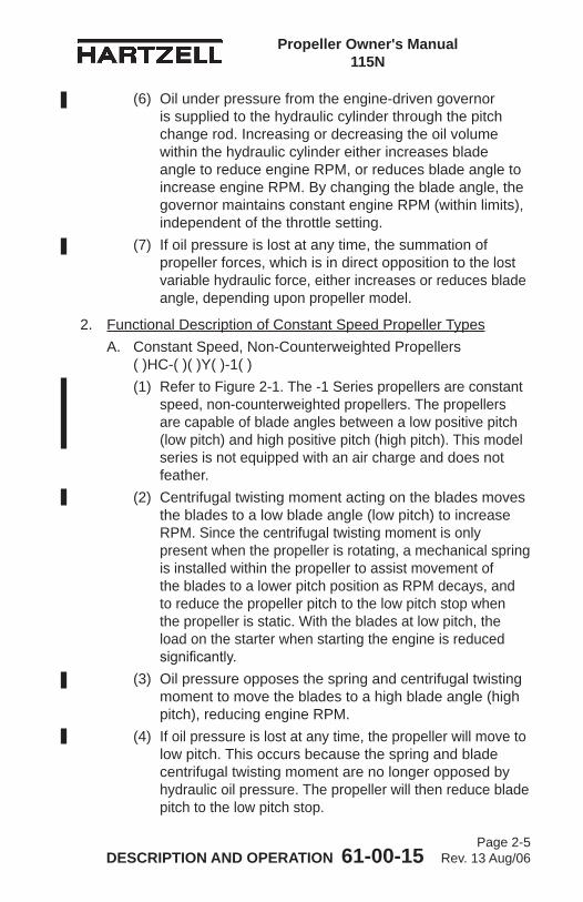
(6) Oil under pressure from the engine-driven governor is supplied to the hydraulic cylinder through the pitch change rod. Increasing or decreasing the oil volume within the hydraulic cylinder either increases blade angle to reduce engine RPM, or reduces blade angle to increase engine RPM. By changing the blade angle, the governor maintains constant engine RPM (within limits), independent of the throttle setting.
(7) If oil pressure is lost at any time, the summation of propeller forces, which is in direct opposition to the lost variable hydraulic force, either increases or reduces blade angle, depending upon propeller model.
2. Functional Description of Constant Speed Propeller TypesA. Constant Speed, Non-Counterweighted Propellers
( )HC-( )( )Y( )-1( )(1) Refer to Figure 2-1. The -1 Series propellers are constant
speed, non-counterweighted propellers. The propellers are capable of blade angles between a low positive pitch (low pitch) and high positive pitch (high pitch). This model series is not equipped with an air charge and does not feather.
(2) Centrifugal twisting moment acting on the blades moves the blades to a low blade angle (low pitch) to increase RPM. Since the centrifugal twisting moment is only present when the propeller is rotating, a mechanical spring is installed within the propeller to assist movement of the blades to a lower pitch position as RPM decays, and to reduce the propeller pitch to the low pitch stop when the propeller is static. With the blades at low pitch, the load on the starter when starting the engine is reduced significantly.
(3) Oil pressure opposes the spring and centrifugal twisting moment to move the blades to a high blade angle (high pitch), reducing engine RPM.
(4) If oil pressure is lost at any time, the propeller will move to low pitch. This occurs because the spring and blade centrifugal twisting moment are no longer opposed by hydraulic oil pressure. The propeller will then reduce blade pitch to the low pitch stop.
Propeller Owner's Manual 115N
DESCRIPTION AND OPERATION 61-00-15 Page 2-6
Rev. 13 Aug/06
Cut
away
of -
2 Se
ries
Con
stan
t Spe
ed, F
eath
erin
g Pr
opel
ler (
)HC
-( )(
)Y( )
-2
Figu
re 2
-2HU
B
BLA
DE
RE
TEN
TIO
N B
EA
RIN
G
PIS
TON
LOW
PIT
CH
STO
P
LUB
RIC
ATIO
N F
ITTI
NG
EN
GIN
E F
LAN
GE
SP
INN
ER
BU
LKH
EA
D
BLA
DE
CO
UN
TER
WE
IGH
TB
ALA
NC
E W
EIG
HTS
SH
AFT
O-R
ING
CY
LIN
DE
R
(OIL
PR
ES
SU
RE
TO
R
ED
UC
E B
LAD
E A
NG
LE
AN
D IN
CR
EA
SE
RP
M)
AP
S61
65
SP
INN
ER
DO
ME
OIL
AIR
CH
AR
GE
RE
MO
VAB
LE
SP
INN
ER
CA
P
STA
RT
LOC
K
LATC
H
SP
RIN
G
FOR
KPIT
CH
CH
AN
GE
R
OD
MO
UN
TIN
G N
UT
(F F
LAN
GE
SH
OW
N)
Propeller Owner's Manual 115N
DESCRIPTION AND OPERATION 61-00-15 Page 2-7
Rev. 13 Aug/06
B. Constant Speed, Feathering Propellers ( )HC-( )( )Y( )-2(1) Refer to Figure 2-2. The -2 Series propellers are constant
speed propellers that use an air charge, spring, and counterweights (if installed) to move the blades to high pitch/feather position. Blade centrifugal twisting moment acts to move the blades to low pitch, but the air charge, spring, and counterweights overcome this force. Oil pressure against a propeller mounted hydraulic piston opposes the counterweight, spring, and air charge forces to move the blades to low blade angle (low pitch).
(2) The action of the air charge, spring, and counterweights tends to move the blades to a higher blade angle (high pitch), reducing engine RPM. Oil pressure toward low pitch increases engine RPM.
(3) If oil pressure is lost during operation, the propeller will feather. Feathering occurs because the air charge, spring, and blade counterweights are no longer opposed by hydraulic oil pressure. The air charge, spring and blade counterweights are then free to increase blade pitch to the feathering (high pitch) stop.
(4) Normalin-flightfeatheringofthesepropellersisaccomplished when the pilot retards the propeller pitch control past the feather detent. This allows control oil to drain from the cylinder and return to the engine sump. The engine can then be shut down.
(5) Normalin-flightunfeatheringisaccomplishedwhen the pilot positions the propeller pitch control into the normalflight(governing)rangeandanenginerestartisattempted.
(6) Some aircraft are equipped with a hydraulic accumulator, which stores a supply of oil under pressure. This oil supply is released to unfeather the propeller during an in-flightenginerestart.Pressurizedoilisdirectedtothepropeller, resulting in blade angle decrease. The propeller begins to windmill, and engine restart is possible.
Propeller Owner's Manual 115N
DESCRIPTION AND OPERATION 61-00-15 Page 2-8
Rev. 13 Aug/06
(7) When the engine is stopped on the ground, it is undesirable to feather the propeller, as the high blade angle inhibits engine starting. To prevent feathering during normal engine shutdown on the ground, the propeller incorporatesspringenergizedlatches.Ifpropellerrotationis approximately 800 RPM or above, the latches are disengaged by centrifugal force acting on the latches to compress the springs. When RPM drops below 800 RPM (and blade angle is typically within 7 degrees of the low pitch stop), the springs overcome the latch weight centrifugal force and move the latches to engage the high pitch stops, preventing blade angle movement to feather during normal engine shutdown.

Propeller Owner's Manual 115N
DESCRIPTION AND OPERATION 61-00-15 Page 2-9
Rev. 13 Aug/06
(This page is intentionally blank)
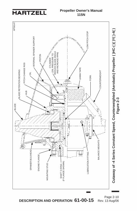
Propeller Owner's Manual 115N
DESCRIPTION AND OPERATION 61-00-15 Page 2-10
Rev. 13 Aug/06
Cut
away
of -
4 Se
ries
Con
stan
t Spe
ed, C
ount
erw
eigh
ted
(Aer
obat
ic) P
rope
ller (
)HC
-( )(
)Y( )
-4( )
Fi
gure
2-3
PIS
TON
LOW
PIT
CH
STO
P
SP
INN
ER
BU
LKH
EA
D
EN
GIN
E F
LAN
GE
SH
AFT
O-R
ING
(F
FLA
NG
E S
HO
WN
)
MO
UN
TIN
G S
TUD
CO
UN
TER
WE
IGH
T
CY
LIN
DE
R
(OIL
PR
ES
SU
RE
TO
R
ED
UC
E B
LAD
E A
NG
LE
AN
D IN
CR
EA
SE
RP
M)
UH
MW
TA
PE
INTE
RN
AL
SP
INN
ER
SU
PP
OR
T
AP
S61
47
OIL
LUB
RIC
ATIO
N F
ITTI
NG
BA
LAN
CE
WE
IGH
TS
FOR
K
PIT
CH
CH
AN
GE
RO
DH
UB
BLA
DE
RE
TEN
TIO
N B
EA
RIN
G
BLA
DE
Propeller Owner's Manual 115N
DESCRIPTION AND OPERATION 61-00-15 Page 2-11
Rev. 13 Aug/06
C. Constant Speed, Counterweighted (Aerobatic) Propellers ( )HC-( )( )Y( )-4( )(1) Refer to Figure 2-3. The -4 Series propellers are
constant speed propellers in which blade mounted counterweight forces act to move the blades to high pitch. This model series is not equipped with an air charge and does not feather. The blade centrifugal twisting moment acts to move the blades to low blade angle (low pitch), but the counterweights are large enoughtoneutralizethisforceandproduceanetincrease in blade angle. Oil pressure against a propeller mounted hydraulic piston opposes the counterweight forces to move the blades to low pitch.
(2) The action of the counterweights tends to move the blades to a high blade angle (high pitch), reducing engine RPM. Oil pressure toward low pitch increases engine RPM.
(3) If oil pressure is lost at any time, the propeller will move to high pitch to avoid overspeeding. Movement to high pitch occurs because the blade counterweights are no longer opposed by hydraulic oil pressure. The blade counterweights are then free to increase blade pitch toward the high pitch stop.
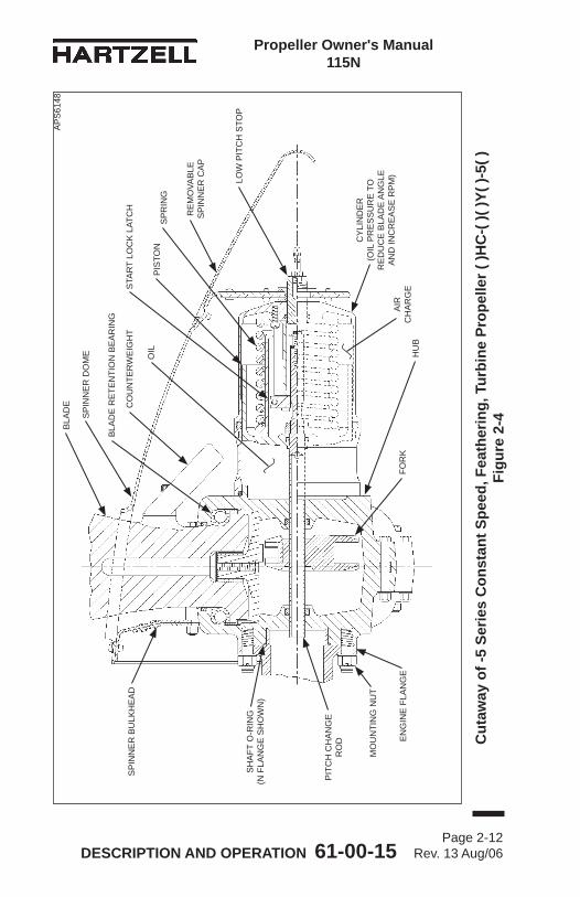
Propeller Owner's Manual 115N
DESCRIPTION AND OPERATION 61-00-15 Page 2-12
Rev. 13 Aug/06
Cut
away
of -
5 Se
ries
Con
stan
t Spe
ed, F
eath
erin
g, T
urbi
ne P
rope
ller (
)HC
-( )(
)Y( )
-5( )
Fi
gure
2-4
HU
B
BLA
DE
RE
TEN
TIO
N B
EA
RIN
G
PIS
TON
LOW
PIT
CH
STO
P
EN
GIN
E F
LAN
GE
SP
INN
ER
BU
LKH
EA
D
BLA
DE CO
UN
TER
WE
IGH
T
MO
UN
TIN
G N
UT
SH
AFT
O-R
ING
(N
FLA
NG
E S
HO
WN
)
CY
LIN
DE
R
(OIL
PR
ES
SU
RE
TO
R
ED
UC
E B
LAD
E A
NG
LE
AN
D IN
CR
EA
SE
RP
M)
AP
S61
48
OIL
SP
INN
ER
DO
ME
RE
MO
VAB
LE
SP
INN
ER
CA
P
STA
RT
LOC
K L
ATC
H
SP
RIN
G
AIR
C
HA
RG
EFO
RK
PIT
CH
CH
AN
GE
R
OD
Propeller Owner's Manual 115N
DESCRIPTION AND OPERATION 61-00-15 Page 2-13
Rev. 14 Jan/09
D. Constant Speed, Feathering, Turbine Propellers ( )HC-( )( )Y( )-5( )(1) Refer to Figure 2-4. The -5 Series propellers are constant
speed propellers that use an air charge, spring, and blade mounted counterweights to move the blades to high pitch/feather position. Blade centrifugal twisting moment acts to move the blades to low pitch, but the air charge, spring, and counterweights overcome this force. Oil pressure against a propeller mounted hydraulic piston opposes the counterweight, spring, and air charge forces to move the blades to low blade angle (low pitch).
(2) The action of the air charge, spring, and counterweights tends to move the blades to a higher blade angle (high pitch), reducing engine RPM. Oil pressure toward low pitch increases engine RPM.
(3) If oil pressure is lost during operation, the propeller will feather. Feathering occurs because the air charge, spring, and counterweights are no longer opposed by hydraulic oil pressure. The air charge, spring, and blade counterweights are then free to increase blade pitch to the feathering (high pitch) stop.
(4) Normalin-flightfeatheringofthesepropellersisaccomplished when the pilot retards the propeller pitch control past the feather detent. This allows control oil to drain from the cylinder and return to the engine sump. The engine may then be shut down.
(5) Normalin-flightunfeatheringoccurswhenthepilotpositionsthepropellerpitchcontrolintothenormalflight(governing) range and restarts the engine. As engine speed increases, oil is directed to the propeller, and blade angle decreases.
Propeller Owner's Manual 115N
DESCRIPTION AND OPERATION 61-00-15 Page 2-14
Rev. 13 Aug/06
(6) In some cases, particularly in seaplane applications, it is undesirable to feather the propeller when the engine is stopped after landing. To prevent feathering during normal engine shutdown, the propeller incorporates spring energizedlatches.Ifpropellerrotationisapproximately800 RPM or above, the latches are disengaged by centrifugal force acting on the latch weights to compress the springs. When RPM drops below 800 RPM (and blade angle is typically within 7 degrees of the low pitch stop), the springs overcome the centrifugal force and move the latches to engage the high pitch stops, preventing blade angle movement to feather.
(7) Start lock latches are not employed on all -5 propellers. Propellers without start lock latches will feather during normal engine shutdown.
Propeller Owner's Manual 115N
DESCRIPTION AND OPERATION 61-00-15 Page 2-15
Rev. 7 Oct/02
(This page is intentionally blank)
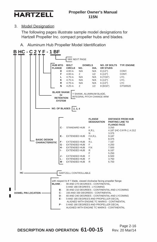
Propeller Owner's Manual 115N
DESCRIPTION AND OPERATION 61-00-15 Page 2-16
Rev. 20 Mar/14
HARTZELL CONTROLLABLE
DOWEL PIN LOCATION
NO. OF BLADES 2, 3, 4
withrespectto#1blade,viewedclockwisefacingpropellerflange:BLANK - 90 AND 270 DEGREES - CONTINENTAL, 0 AND 180 DEGREES - LYCOMING B - 30 AND 210 DEGREES - CONTINENTAL AND LYCOMING C - 150 AND 330 DEGREES - CONTINENTAL D - 60 AND 240 DEGREES - CONTINENTAL AND LYCOMING E - 0 AND 180 DEGREES AND PROPELLER DECAL ALIGNED WITH ENGINE TC MARKS - CONTINENTAL P - 0 AND 180 DEGREES AND PROPELLER DECAL ALIGNED WITH ENGINE TC MARKS - CONTINENTAL
B HC - C 2 Y F - 1 BF
BLADE SHANK Or
RETENTION SYSTEM
Y SHANK, ALUMINUM BLADE, INTEGRAL PITCH CHANGE ARM
FLANGE DISTANCE FROM HUB DESIGNATION PARTING LINE TO FLANGE FACEC - STANDARD HUB F 3.250 K,R,L 4.187 (HC-C4YR-( ) 4.312 N 3.375E - EXTENDED HUB F,K,R,L 9.187 N 8.375F - EXTENDED HUB R,L 7.187G - EXTENDED HUB F 4.250H - EXTENDED HUB F,N 7.500I - EXTENDED HUB R 6.187 F 5.250J - EXTENDED HUB F 6.500L - EXTENDED HUB F 3.750M - EXTENDED HUB R 6.750
HUB MTG BOLT DOWELS NO. OF BOLTS TYP. ENGINE FLANGE CIRCLE NO. DIA. OR STUDS D 4.00 in. N/A N/A 8 (1/2") CONT. F 4.00 in. 2 1/2 6 (1/2") CONT. L 4.75 in. N/A N/A 6 (7/16") LYC. K 4.75 in. N/A N/A 6 (1/2") LYC, R 4.75 in. N/A N/A 6 (1/2") LYC N 4.25 in. 2 1/2 8 (9/16") GTSI0520
BASIC DESIGN CHARACTERISTIC
SEE NEXT PAGE
HC
A. AluminumHubPropellerModelIdentification
3. Model DesignationThe following pages illustrate sample model designations for HartzellPropellerInc.compactpropellerhubsandblades.
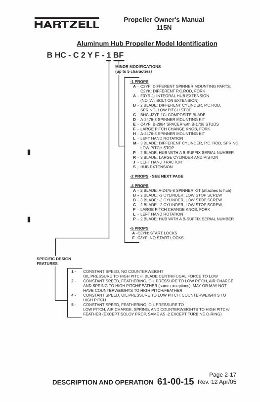
Propeller Owner's Manual 115N
DESCRIPTION AND OPERATION 61-00-15 Page 2-17
Rev. 12 Apr/05
B HC - C 2 Y F - 1 BF
1 - CONSTANT SPEED, NO COUNTERWEIGHT OIL PRESSURE TO HIGH PITCH, BLADE CENTRIFUGAL FORCE TO LOW2 - CONSTANT SPEED, FEATHERING, OIL PRESSURE TO LOW PITCH, AIR CHARGE AND SPRING TO HIGH PITCH/FEATHER (some exceptions), MAY OR MAY NOT HAVE COUNTERWEIGHTS TO HIGH PITCH/FEATHER4 - CONSTANT SPEED, OIL PRESSURE TO LOW PITCH, COUNTERWEIGHTS TO HIGH PITCH5 - CONSTANT SPEED, FEATHERING, OIL PRESSURE TO LOW PITCH, AIR CHARGE, SPRING, AND COUNTERWEIGHTS TO HIGH PITCH/ FEATHER (EXCEPT SOLOY PROP, SAME AS -2 EXCEPT TURBINE O-RING)
-1 PROPS A - C2YF: DIFFERENT SPINNER MOUNTING PARTS; C2YK: DIFFERENT P.C.ROD, FORK A - F3YR-1: INTEGRAL HUB EXTENSION (NO "A": BOLT ON EXTENSION) B - 2 BLADE: DIFFERENT CYLINDER, P.C.ROD, SPRING, LOW PITCH STOP C - BHC-J2YF-1C: COMPOSITE BLADE D - A-2476-3 SPINNER MOUNTING KIT E - C4YF: B-2984 SPACER with B-1738 STUDS F - LARGE PITCH CHANGE KNOB, FORK H - A-2476-8 SPINNER MOUNTING KIT L - LEFT HAND ROTATION M - 3 BLADE: DIFFERENT CYLINDER, P.C. ROD, SPRING, LOW PITCH STOP P - 2 BLADE: HUB WITH A B-SUFFIX SERIAL NUMBER R - 3 BLADE: LARGE CYLINDER AND PISTON J - LEFT HAND TRACTOR S - HUB EXTENSION
-2 PROPS - SEE NEXT PAGE
-4 PROPS A - 2 BLADE: A-2476-8 SPINNER KIT (attaches to hub) B - 2 BLADE: -2 CYLINDER, LOW STOP SCREW B - 3 BLADE: -2 CYLINDER, LOW STOP SCREW C - 2 BLADE: -2 CYLINDER, LOW STOP SCREW, F - LARGE PITCH CHANGE KNOB, FORK L - LEFT HAND ROTATION P - 2 BLADE: HUB WITH A B-SUFFIX SERIAL NUMBER
-5 PROPS A - C3YN: START LOCKS F - C3YF: NO START LOCKS
SPECIFIC DESIGN FEATURES
MINOR MODIFICATIONS (up to 5 characters)
Aluminum Hub Propeller Model Identification
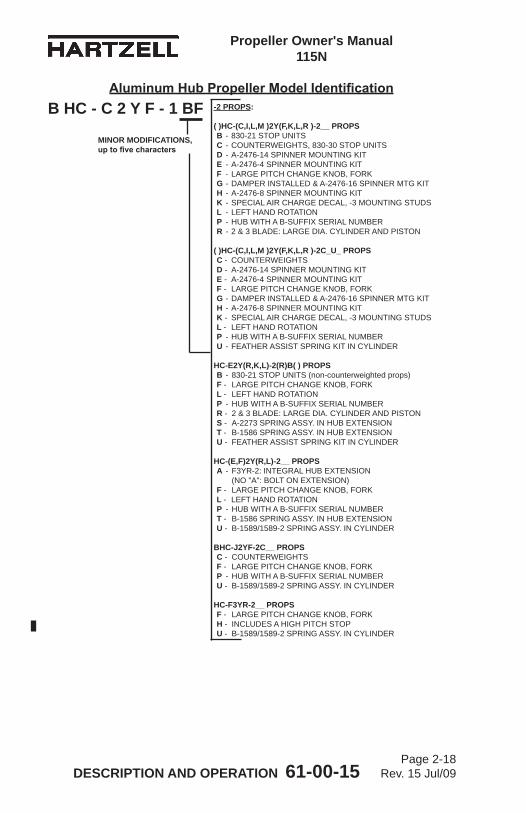
Propeller Owner's Manual 115N
DESCRIPTION AND OPERATION 61-00-15 Page 2-18
Rev. 15 Jul/09
B HC - C 2 Y F - 1 BF
MINOR MODIFICATIONS, up to five characters
-2 PROPS:
( )HC-(C,I,L,M )2Y(F,K,L,R )-2__ PROPS B - 830-21 STOP UNITS C - COUNTERWEIGHTS, 830-30 STOP UNITS D - A-2476-14 SPINNER MOUNTING KIT E - A-2476-4 SPINNER MOUNTING KIT F - LARGE PITCH CHANGE KNOB, FORK G - DAMPER INSTALLED & A-2476-16 SPINNER MTG KIT H - A-2476-8 SPINNER MOUNTING KIT K - SPECIAL AIR CHARGE DECAL, -3 MOUNTING STUDS L - LEFT HAND ROTATION P - HUB WITH A B-SUFFIX SERIAL NUMBER R - 2 & 3 BLADE: LARGE DIA. CYLINDER AND PISTON
( )HC-(C,I,L,M )2Y(F,K,L,R )-2C_U_ PROPS C - COUNTERWEIGHTS D - A-2476-14 SPINNER MOUNTING KIT E - A-2476-4 SPINNER MOUNTING KIT F - LARGE PITCH CHANGE KNOB, FORK G - DAMPER INSTALLED & A-2476-16 SPINNER MTG KIT H - A-2476-8 SPINNER MOUNTING KIT K - SPECIAL AIR CHARGE DECAL, -3 MOUNTING STUDS L - LEFT HAND ROTATION P - HUB WITH A B-SUFFIX SERIAL NUMBER U - FEATHER ASSIST SPRING KIT IN CYLINDER
HC-E2Y(R,K,L)-2(R)B( ) PROPS B - 830-21 STOP UNITS (non-counterweighted props) F - LARGE PITCH CHANGE KNOB, FORK L - LEFT HAND ROTATION P - HUB WITH A B-SUFFIX SERIAL NUMBER R - 2 & 3 BLADE: LARGE DIA. CYLINDER AND PISTON S - A-2273 SPRING ASSY. IN HUB EXTENSION T - B-1586 SPRING ASSY. IN HUB EXTENSION U - FEATHER ASSIST SPRING KIT IN CYLINDER
HC-(E,F)2Y(R,L)-2__ PROPS A - F3YR-2: INTEGRAL HUB EXTENSION (NO "A": BOLT ON EXTENSION) F - LARGE PITCH CHANGE KNOB, FORK L - LEFT HAND ROTATION P - HUB WITH A B-SUFFIX SERIAL NUMBER T - B-1586 SPRING ASSY. IN HUB EXTENSION U - B-1589/1589-2 SPRING ASSY. IN CYLINDER
BHC-J2YF-2C__ PROPS C - COUNTERWEIGHTS F - LARGE PITCH CHANGE KNOB, FORK P - HUB WITH A B-SUFFIX SERIAL NUMBER U - B-1589/1589-2 SPRING ASSY. IN CYLINDER
HC-F3YR-2__ PROPS F - LARGE PITCH CHANGE KNOB, FORK H - INCLUDES A HIGH PITCH STOP U - B-1589/1589-2 SPRING ASSY. IN CYLINDER
Aluminum Hub Propeller Model Identification
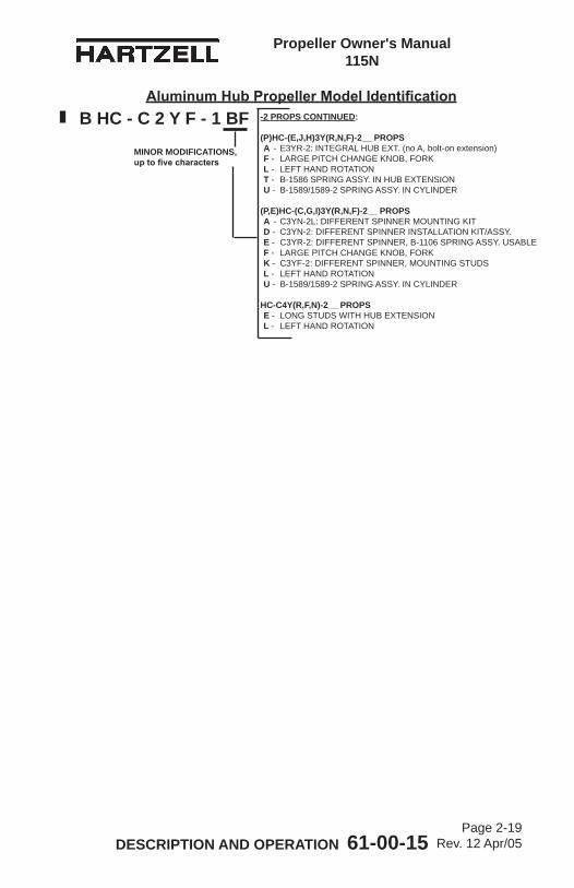
Propeller Owner's Manual 115N
DESCRIPTION AND OPERATION 61-00-15 Page 2-19
Rev. 12 Apr/05
B HC - C 2 Y F - 1 BF
MINOR MODIFICATIONS, up to five characters
-2 PROPS CONTINUED:
(P)HC-(E,J,H)3Y(R,N,F)-2__ PROPS A - E3YR-2: INTEGRAL HUB EXT. (no A, bolt-on extension) F - LARGE PITCH CHANGE KNOB, FORK L - LEFT HAND ROTATION T - B-1586 SPRING ASSY. IN HUB EXTENSION U - B-1589/1589-2 SPRING ASSY. IN CYLINDER
(P,E)HC-(C,G,I)3Y(R,N,F)-2__ PROPS A - C3YN-2L: DIFFERENT SPINNER MOUNTING KIT D - C3YN-2: DIFFERENT SPINNER INSTALLATION KIT/ASSY. E - C3YR-2: DIFFERENT SPINNER, B-1106 SPRING ASSY. USABLE F - LARGE PITCH CHANGE KNOB, FORK K - C3YF-2: DIFFERENT SPINNER, MOUNTING STUDS L - LEFT HAND ROTATION U - B-1589/1589-2 SPRING ASSY. IN CYLINDER
HC-C4Y(R,F,N)-2__ PROPS E - LONG STUDS WITH HUB EXTENSION L - LEFT HAND ROTATION
Aluminum Hub Propeller Model Identification
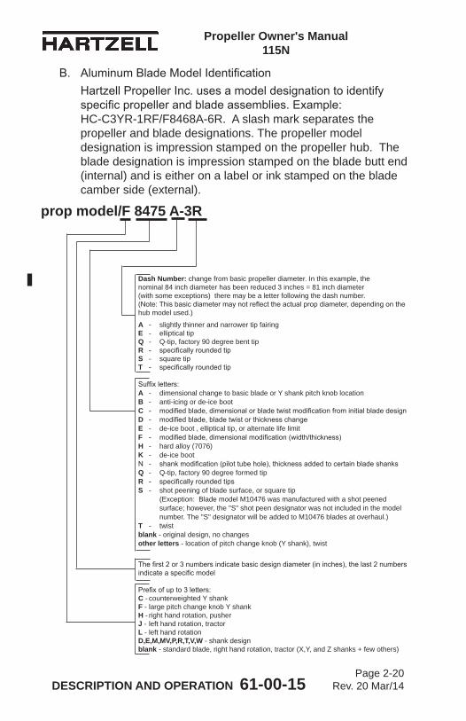
Propeller Owner's Manual 115N
DESCRIPTION AND OPERATION 61-00-15 Page 2-20
Rev. 20 Mar/14
Dash Number: change from basic propeller diameter. In this example, the nominal 84 inch diameter has been reduced 3 inches = 81 inch diameter (with some exceptions) there may be a letter following the dash number. (Note:Thisbasicdiametermaynotreflecttheactualpropdiameter,dependingonthehub model used.)
A - slightly thinner and narrower tip fairing E - elliptical tip Q - Q-tip, factory 90 degree bent tip R - specificallyroundedtip S - square tip T - specificallyroundedtip Suffixletters: A - dimensional change to basic blade or Y shank pitch knob location B - anti-icing or de-ice boot C - modifiedblade,dimensionalorbladetwistmodificationfrominitialbladedesignD - modifiedblade,bladetwistorthicknesschange E - de-ice boot , elliptical tip, or alternate life limit F - modifiedblade,dimensionalmodification(width/thickness) H - hard alloy (7076) K - de-ice boot N - shankmodification(pilottubehole),thicknessaddedtocertainbladeshanks Q - Q-tip, factory 90 degree formed tip R - specificallyroundedtips S - shot peening of blade surface, or square tip (Exception: Blade model M10476 was manufactured with a shot peened surface; however, the "S" shot peen designator was not included in the model number. The "S" designator will be added to M10476 blades at overhaul.) T - twist blank - original design, no changes other letters - location of pitch change knob (Y shank), twist
Thefirst2or3numbersindicatebasicdesigndiameter(ininches),thelast2numbersindicateaspecificmodel Prefixofupto3letters: C - counterweighted Y shank F - large pitch change knob Y shank H - right hand rotation, pusher J - left hand rotation, tractor L - left hand rotation D,E,M,MV,P,R,T,V,W - shank design blank - standard blade, right hand rotation, tractor (X,Y, and Z shanks + few others)
B. AluminumBladeModelIdentificationHartzellPropellerInc.usesamodeldesignationtoidentifyspecificpropellerandbladeassemblies.Example: HC-C3YR-1RF/F8468A-6R. A slash mark separates the propeller and blade designations. The propeller model designation is impression stamped on the propeller hub. The blade designation is impression stamped on the blade butt end (internal) and is either on a label or ink stamped on the blade camber side (external).
prop model/F 8475 A-3R

Propeller Owner's Manual 115N
DESCRIPTION AND OPERATION 61-00-15 Page 2-21
Rev. 16 Oct/09
(This page is intentionally blank.)
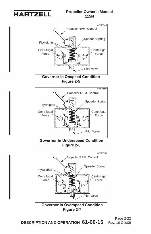
Propeller Owner's Manual 115N
DESCRIPTION AND OPERATION 61-00-15 Page 2-22
Rev. 16 Oct/09
Governor in Onspeed Condition Figure 2-5
Governor in Underspeed Condition Figure 2-6
Governor in Overspeed Condition Figure 2-7
Propeller RPM Control
Speeder SpringFlyweights
Pilot Valve
Speeder SpringFlyweights
Pilot Valve
Speeder SpringFlyweights
Pilot Valve
APS6149
APS6150
APS6151
Centrifugal Force
Centrifugal Force
Centrifugal Force
Centrifugal Force
Centrifugal Force
Centrifugal Force
Propeller RPM Control
Propeller RPM Control
Propeller Owner's Manual 115N
DESCRIPTION AND OPERATION 61-00-15 Page 2-23
Rev. 12 Apr/05
4. GovernorsA. Theory of Operation
(1) A governor is an engine RPM sensing device and high pressure oil pump. In a constant speed propeller system, the governor responds to a change in engine RPM by directing oil under pressure to the propeller hydraulic cylinder or by releasing oil from the hydraulic cylinder. The change in oil volume in the hydraulic cylinder changes the blade angle and maintains the propeller system RPM. The governorissetforaspecificRPMviathecockpitpropellercontrol, which compresses or releases the governor speeder spring.
(2) When the engine is operating at the RPM set by the pilot using the cockpit control, the governor is operating onspeed. Refer to Figure 2-5. In an onspeed condition, thecentrifugalforceactingontheflyweightsisbalancedby the speeder spring, and the pilot valve is neither directing oil to nor from the propeller hydraulic cylinder.
(3) When the engine is operating below the RPM set by the pilot using the cockpit control, the governor is operating underspeed. Refer to Figure 2-6. In an underspeed condition,theflyweightstiltinwardbecausethereisnotenoughcentrifugalforceontheflyweightstoovercomethe force of the speeder spring. The pilot valve, forced down by thespeederspring,metersoilflowtodecreasepropellerpitch and raise engine RPM.
(4) When the engine is operating above the RPM set by the pilot using the cockpit control, the governor is operating overspeed. Refer to Figure 2-7. In an overspeed condition,thecentrifugalforceactingontheflyweightsis greaterthanthespeederspringforce.Theflyweightstiltoutward, and raise the pilot valve. The pilot valve then metersoilflowtoincreasepropellerpitchandlowerengine RPM.
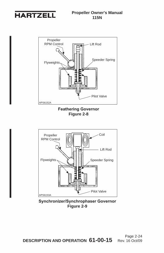
Propeller Owner's Manual 115N
DESCRIPTION AND OPERATION 61-00-15 Page 2-24
Rev. 16 Oct/09
Feathering Governor Figure 2-8
Speeder SpringFlyweights
Pilot Valve
Lift Rod
Synchronizer/Synchrophaser Governor Figure 2-9
Propeller RPM Control
Speeder SpringFlyweights
Pilot Valve
Coil
Lift Rod
APS6152A
APS6153A
Propeller RPM Control
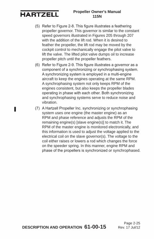
Propeller Owner's Manual 115N
DESCRIPTION AND OPERATION 61-00-15 Page 2-25
Rev. 17 Jul/12
(5) RefertoFigure2-8.Thisfigureillustratesafeatheringpropeller governor. This governor is similar to the constant speed governors illustrated in Figures 205 through 207 with the addition of the lift rod. When it is desired to feather the propeller, the lift rod may be moved by the cockpit control to mechanically engage the pilot valve to lift the valve. The lifted pilot valve dumps oil to increase propeller pitch until the propeller feathers.
(6) RefertoFigure2-9.Thisfigureillustratesagovernorasacomponentofasynchronizingorsynchrophasingsystem.Asynchronizingsystemisemployedinamulti-engineaircraft to keep the engines operating at the same RPM. A synchrophasing system not only keeps RPM of the engines consistent, but also keeps the propeller blades operatinginphasewitheachother.Bothsynchronizingand synchrophasing systems serve to reduce noise and vibration.
(7) AHartzellPropellerInc.synchronizingorsynchrophasingsystem uses one engine (the master engine) as an RPM and phase reference and adjusts the RPM of the remaining engine(s) [slave engine(s)] to match it. The RPM of the master engine is monitored electronically, and this information is used to adjust the voltage applied to the electrical coil on the slave governor(s). The voltage to the coil either raises or lowers a rod which changes the force on the speeder spring. In this manner, engine RPM and phaseofthepropellersissynchronizedorsynchrophased.
Propeller Owner's Manual 115N
DESCRIPTION AND OPERATION 61-00-15 Page 2-26
Rev. 17 Jul/12
B. Governor TypesThegovernorscommonlyusedinHartzellPropellerInc.Compact Constant Speed propeller systems are supplied eitherbyHartzellorseveralothermanufacturers.Thesegovernor types function in a similar manner.
C. IdentificationofHartzellPropellerInc.GovernorsAHartzellgovernormaybeidentifiedbyitsmodelnumberasfollows: Ex. F-6-4.
NOTE: RefertoHartzellPropellerInc.Manual130B(61-23-30)formaintenanceandoverhaulinstructionsforHartzellPropeller Inc. governors.
(X) - (X) - (X)
Minor variation of basic design. (Numeric and/or alpha character)
Specificmodelapplication (numeric character) - special attributes
Basic Body and Major Parts Modification(alphacharacter)
Propeller Owner's Manual 115N
DESCRIPTION AND OPERATION 61-00-15 Page 2-27
Rev. 14 Jan/09
(This page is intentionally blank.)
Propeller Owner's Manual 115N
DESCRIPTION AND OPERATION 61-00-15 Page 2-28
Rev. 14 Jan/09
Gov
erno
r/Acc
umul
ator
Sys
tem
Fi
gure
2-1
0
Pro
pelle
r Con
trol O
il
Pro
pelle
r
Gov
erno
r
Eng
ine
Oil
Eng
ine
Cha
rge
Valv
e
Acc
umul
ator
Air
or N
itrog
en
Pis
ton
Oil Gov
erno
r To
A
ccum
ulat
or
Con
nect
ion
Oil
Dra
in
TI-0
0174
Propeller Owner's Manual 115N
DESCRIPTION AND OPERATION 61-00-15 Page 2-29
Rev. 17 Jul/12
5. AccumulatorA. System Overview
(1) An unfeathering accumulator is a device that stores a volume of oil at a pressure and supplies it to the propeller, when commanded by the pilot/governor, to move the propeller piston and the connected blades to a lower blade angle for the purpose of starting the associated engine. Lower blade angles will cause the propeller to windmill and make the engine easier to start.
(2) HartzellPropellerInc.manufacturesanaccumulatorthatis a cylinder with a moveable internal piston. One end ofthecylinderandpistonisfilledwithengineoilthroughafitting,andtheotherendofthecylinderandpistonisfilledwithairornitrogentoapressurethroughanairvalve. The accumulator is a self contained unit and is usually installed at some remote location in the engine compartment. An oil supply hose is connected between the accumulator and the governor.
(3) Thegovernorhasafittingorthreadedholetoattachwith an oil supply hose that is connected to the accumulator on the other end. During operation of the engine and propeller, the governor supplies oil to the accumulator and maintains oil in the accumulator during engine operation.
(4) The pilot commands feather of the propeller by moving the RPM control of the governor toward lower RPM to reach the feather command location. The governor disconnects the oil supply to the accumulator and seals a volume of oil under pressure in the accumulator. The governor then connects the oil supply line between governor and propeller to drain oil from the propeller piston and permit the propeller blades to move to a feather stop in the propeller.
Propeller Owner's Manual 115N
DESCRIPTION AND OPERATION 61-00-15 Page 2-30
Rev. 17 Jul/12
(5) Unfeathering occurs when the governor RPM control is moved by the pilot from the feather location to a higher RPM selection for governing. The governor disconnects the propeller oil supply from drain and reconnects it to the governed oil supply line from the governor. At that point there is no oil available from the engine oil pump to the governor; therefore, no governed oil is available from the governor for controlling the propeller blade angle and RPM. Further movement of the governor RPM control toward higher RPM will cause the governor to connect the accumulator to the oil supply line from governor to the propeller. The air or nitrogen pressure in one side of the accumulator will push a piston to force oil from the other side of the accumulator through the governor to the propeller piston to move the propeller blades from feather to a lower blade angle. The propeller will then begin to windmill and will permit the engine to start.
(6) HartzellPropellerInc.manufacturersgovernorsthathave unfeathering and feathering capability, although governors that are able to feather a propeller are not automatically capable of unfeathering the propeller.
Propeller Owner's Manual 115N
DESCRIPTION AND OPERATION 61-00-15 Page 2-31
Rev. 17 Jul/12
6. Propeller Ice Protection SystemsSomeHartzellPropellerInc.compactpropellersmaybeequippedwith an anti-ice or a de-ice system. A short description of each of these systems follows:A. Propeller Anti-ice System
A propeller anti-ice system is a system that prevents ice from forming on propeller surfaces. The system dispenses a liquid (usually isopropyl alcohol) which mixes with moisture on the propellerblades,reducingthefreezingpointofthewater. Thiswater/alcoholmixtureflowsoffthebladesbeforeiceforms. This system must be in use before ice forms. It is ineffective in removing ice that has already formed.(1) System Overview
(a) Atypicalanti-icesystemconsistsofafluidtank,pump, and distribution tubing.
(b) Therateatwhichtheanti-icingfluidisdispensediscontrolled by a pump speed rheostat in the cockpit.
(c) Theanti-icingfluidisdispensedthroughairframemounted distribution tubing and into a rotating slinger ring mounted on the rear of the propeller hub. Theanti-icingfluidisthendirectedthroughbladefeed tubes from the slinger ring onto the blades via centrifugalforce.Theanti-icingfluidisdirectedontoanti-icing boots that are attached to the leading edge of the blade. These anti-icing boots evenly distribute anddirectthefluidalongthebladeleadingedge.
Propeller Owner's Manual 115N
DESCRIPTION AND OPERATION 61-00-15 Page 2-32
Rev. 12 Apr/05
B. Propeller De-ice SystemA propeller de-ice system is a system that allows ice to form, and then removes it by electrically heating the de-ice boots. The ice partially melts and is thrown from the blade by centrifugal force.(1) System Overview
(a) A de-ice system consists of one or more on/off switches, a timer or cycling unit, a slip ring, brush blocks, and de-ice boots. The pilot controls the operation of the de-ice system by turning on one or more switches. All de-ice systems have a master switch, and may have another toggle switch for each propeller. Some systems also have a selector switch to adjust for light or heavy icing conditions.
(b) The timer or cycling unit determines the sequence of which blades (or portion thereof) are currently being de-iced, and for what length of time. The cycling unit applies power to each de-ice boot or boot segment in a sequential order.
(c) A brush block, which is normally mounted on the engine just behind the propeller, is used to transfer electricity to the slip ring. The slip ring rotates with the propeller, and provides a current path to the blade de-ice boots.
(d) De-ice boots contain internal heating elements. These boots are securely attached to the leading edges of each blade with adhesive.
Propeller Owner's Manual 115N
INSTALLATION AND REMOVAL 61-00-15 Page 3-1
Rev. 17 Jul/12
INSTALLATION AND REMOVAL- CONTENTS
1. Tools, Consumables, and Expendables ...................................3-5A. Tooling ...............................................................................3-5B. Consumables .....................................................................3-9C. Expendables ......................................................................3-9
2. Pre-Installation .........................................................................3-9A. Inspection of Shipping Package ........................................3-9B. Uncrating ...........................................................................3-9C. Inspection after Shipment ..................................................3-9D. Reassembly of a Propeller Disassembled for Shipment ...3-9E. Air Charge Pressure Check (-2 and -5 Propellers) ............3-9
3. Spinner Pre-Installation ..........................................................3-11A. General ............................................................................3-11B. Installation of a Metal Spinner Bulkhead on the
Propeller Hub ...................................................................3-13C. Installation of a Composite Spinner Bulkhead on a
Propeller Hub ....................................................................3-15D. Spinner Adapter to Starter Ring Gear Installation ...........3-17
4. Propeller Installation ..............................................................3-19A. Flange Description ...........................................................3-19B. Installation of “D” Flange Propellers ................................3-21C. Installation of “F” Flange Propellers .................................3-27D. Installation of “N” Flange Propellers ................................3-30E. Installation of “L” Flange Propellers (except model
HC-E2YL-[ ]) ........................................................................3-35F. Installation of HC-E2YL-( ) Propellers ............................3-38G. Installation of “K” and “R” Flange Propellers ...................3-42
5. Damper Installation ...............................................................3-47A. Installation of C-1576 Damper (Hartzell Propeller Inc.
Kit A-1583) .......................................................................3-476. Spinner Installation ................................................................3-47
A. Single Piece Spinner Dome .............................................3-47B. Two-Piece Spinner Dome (Procedure 1) .........................3-49C. Two-Piece Spinner Dome (Procedure 2) .........................3-51
7. Post-Installation Checks ........................................................3-52
Propeller Owner's Manual 115N
INSTALLATION AND REMOVAL 61-00-15 Page 3-2
Rev. 14 Jan/09
8. Spinner Removal ..................................................................3-52A. Removal of Single Piece Spinner ....................................3-52B. Removal of Two-Piece Spinner .......................................3-52C. Hub Mounted Spinner Bulkhead Removal ......................3-52D. Starter Ring Gear Spinner Adapter Removal ..................3-53
9. Propeller Removal .................................................................3-53A. Removal of “D” Flange Propellers ...................................3-53B. Removal of “F” Flange Propellers ....................................3-55C. Removal of “N” Flange Propellers ...................................3-57D. Removal of “L” Flange Propellers
(except model HC-E2YL-[ ]) ............................................ 3-59E. Removal of HC-E2YL-( ) Propellers ...............................3-61F. Removal of “K” and “R” Flange Propellers ......................3-63
INSTALLATION AND REMOVAL - CONTENTS, CONTINUED
Propeller Owner's Manual 115N
INSTALLATION AND REMOVAL 61-00-15 Page 3-3
Rev. 17 Jul/12
LIST OF FIGURES
Determining Torque Value When Using Torquing Adapter ...................................... Figure 3-1 ..............3-6
Diagram of Torquing Sequence for Propeller Mounting Hardware ............ Figure 3-2 ..............3-8
Hub Clamping Bolt Location ........................... Figure 3-3 ............3-10
Metal Bulkhead and Spinner Mounting (Hub Mounted Spinner) ............................ Figure 3-4 ............3-12
Composite Bulkhead and Spinner Mounting (Hub Mounted Spinner) ............................ Figure 3-5 ............3-14
Spinner Adapter and Spinner Mounting (Starter Ring Gear Mount) ....................... Figure 3-6 ............3-16
“D” Flange Propeller Mounting ....................... Figure 3-7 ............3-20
“F” and “N” Flange Propeller Mounting ........... Figure 3-8 ............3-26
“L”, “K”, and “R” Flange Propeller Mounting ... Figure 3-9 ............3-34
Damper Installation........................................ Figure 3-10 ...........3-46
Two Piece Spinner Mounting (Procedure 1) .. Figure 3-11 ...........3-48
Two Piece Spinner Mounting (Procedure 2) .. Figure 3-12 ...........3-50
Spinner Dome to Bulkhead Mounting Hole Alignment ........................................ Figure 3-13 ...........3-50
LIST OF TABLES
Torque Table .................................................... Table 3-1 ...............3-7
Metal Spinner Bulkhead Mounting Hardware ................................... Table 3-2 .............3-13
Composite Spinner Bulkhead Mounting Hardware .................................................. Table 3-3 .............3-15
Propeller/Engine Flange O-rings and Mounting Hardware ............................ Table 3-4 .............3-18
Spinner Dome and Spinner Cap Mounting Hardware ................................... Table 3-5 .............3-46
Propeller Owner's Manual 115N
INSTALLATION AND REMOVAL 61-00-15 Page 3-4
Rev. 14 Jan/09
(This page is intentionally blank.)
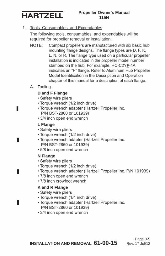
Propeller Owner's Manual 115N
INSTALLATION AND REMOVAL 61-00-15 Page 3-5
Rev. 17 Jul/12
1. Tools, Consumables, and ExpendablesThe following tools, consumables, and expendables will be required for propeller removal or installation:NOTE: Compact propellers are manufactured with six basic hub
mounting flange designs. The flange types are D, F, K, L, N, or R. The flange type used on a particular propeller installation is indicated in the propeller model number stamped on the hub. For example, HC-C2YF-4A indicates an “F” flange. Refer to Aluminum Hub Propeller Model Identification in the Description and Operation chapter of this manual for a description of each flange.
A. ToolingD and F Flange • Safety wire pliers • Torque wrench (1/2 inch drive) • Torque wrench adapter (Hartzell Propeller Inc. P/N BST-2860 or 101939) • 3/4 inch open end wrenchL Flange • Safety wire pliers • Torque wrench (1/2 inch drive) • Torque wrench adapter (Hartzell Propeller Inc. P/N BST-2860 or 101939) • 5/8 inch open end wrenchN Flange • Safety wire pliers • Torque wrench (1/2 inch drive) • Torque wrench adapter (Hartzell Propeller Inc. P/N 101939) • 7/8 inch open end wrench • 7/8 inch crowfoot wrenchK and R Flange • Safety wire pliers • Torque wrench (1/4 inch drive) • Torque wrench adapter (Hartzell Propeller Inc. P/N BST-2860 or 101939) • 3/4 inch open end wrench
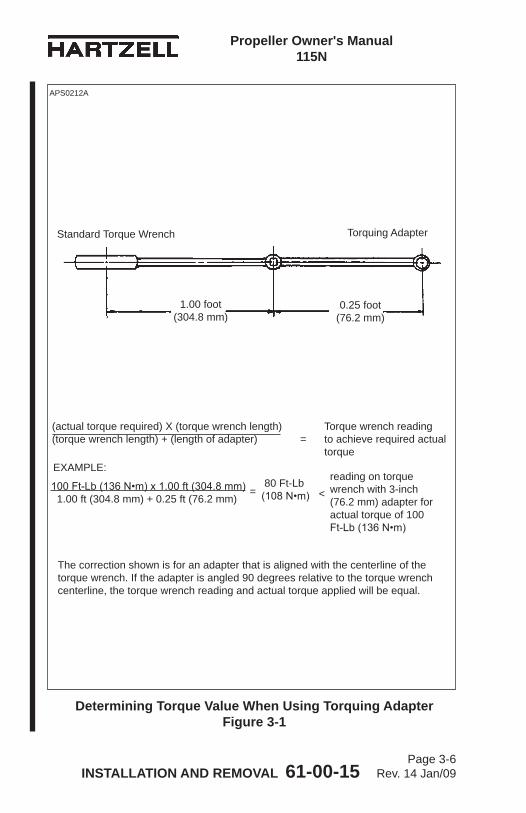
Propeller Owner's Manual 115N
INSTALLATION AND REMOVAL 61-00-15 Page 3-6
Rev. 14 Jan/09
(actual torque required) X (torque wrench length) Torque wrench reading (torque wrench length) + (length of adapter) = to achieve required actual torque
Determining Torque Value When Using Torquing Adapter Figure 3-1
APS0212A
0.25 foot(76.2 mm)
1.00 foot(304.8 mm)
Standard Torque Wrench Torquing Adapter
100 Ft-Lb (136 N•m) x 1.00 ft (304.8 mm) 1.00 ft (304.8 mm) + 0.25 ft (76.2 mm)
reading on torque wrench with 3-inch (76.2 mm) adapter for actual torque of 100 Ft-Lb (136 N•m)
EXAMPLE:
= < 80 Ft-Lb(108 N•m)
The correction shown is for an adapter that is aligned with the centerline of the torque wrench. If the adapter is angled 90 degrees relative to the torque wrench centerline, the torque wrench reading and actual torque applied will be equal.
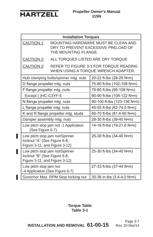
Propeller Owner's Manual 115N
INSTALLATION AND REMOVAL 61-00-15 Page 3-7
Rev. 20 Mar/14
Installation TorquesCAUTION 1: MOUNTING HARDWARE MUST BE CLEAN AND
DRY TO PREVENT EXCESSIVE PRELOAD OF THE MOUNTING FLANGE.
CAUTION 2: ALL TORQUES LISTED ARE DRY TORQUE.
CAUTION 3: REFER TO FIGURE 3-1 FOR TORQUE READING WHEN USING A TORQUE WRENCH ADAPTER.
Hub clamping bolts/spinner mtg. nuts 20-22 ft-lbs (28-29 N•m)D flange propeller mtg. nuts 75-80 ft-lbs (102-108 N•m)F flange propeller mtg. nuts 70-80 ft-lbs (95-108 N•m) Except ( )HC-C3YF-5 80-90 ft-lbs (108-122 N•m)N flange propeller mtg. nuts 90-100 ft-lbs (123-136 N•m)L flange propeller mtg. nuts 45-55 ft-lbs (62-74.5 N•m)K and R flange propeller mtg. studs 60-70 ft-lbs (81.4-95 N•m)Damper assembly mtg. nuts 28-30 ft-lbs (38-40 N•m)Low pitch stop jam nut -1 Application
(See Figure 6-7)14-16 ft-lbs (19-21.6 N•m)
Low pitch stop jam nut/Spinner locknut “A” (See Figure 6-8, Figure 3-11, and Figure 3-12)
25-30 ft-lbs (34-40 N•m)
Low pitch stop jam nut/Spinner locknut “B” (See Figure 6-8, Figure 3-11, and Figure 3-12)
25-30 ft-lbs (34-40 N•m)
Low pitch stop jam nut -4 Application (See Figure 6-7)
27-33 ft-lbs (37-44 N•m)
Governor Max. RPM Stop locking nut 30-36 in-lbs (3.4-4.0 N•m)
Torque Table Table 3-1
Propeller Owner's Manual 115N
INSTALLATION AND REMOVAL 61-00-15 Page 3-8
Rev. 14 Jan/09
Diagram of Torquing Sequence for Propeller Mounting Hardware Figure 3-2
F FlangeStep 1 - Torque all mounting nuts to
40 Ft-Lbs (54 N•m) in the sequence shown
Step 2 - Torque all mounting nuts in accordance with Table 3-1 and Figure 3-1 in the sequence shown
1
2
3
45
6
1
2
3
4
5 6
R FlangeStep 1 - Torque all mounting studs to
40 Ft-Lbs (54 N•m) in the sequence shown
Step 2 - Torque all mounting studs in accordance with Table 3-1 and Figure 3-1 in the sequence shown
1
2
3
4
5 6
TI-0050 TI-0051
Propeller Owner's Manual 115N
INSTALLATION AND REMOVAL 61-00-15 Page 3-9
Rev. 17 Jul/12
B. Consumables• Quick Dry Stoddard Solvent or Methyl-Ethyl-Ketone (MEK)
C. Expendables• 0.032 Stainless Steel Aircraft Safety wire • O-ring - propeller to engine seal (see Table 3-4)
2. Pre-InstallationA. Inspection of Shipping Package
(1) Examine the exterior of the shipping container for signs of shipping damage, especially at the box ends around each blade. A hole, tear or crushed appearance at the end of the box (at the propeller tips) may indicate the propeller was dropped during shipment, possibly damaging the blades.
B. Uncrating(1) Place the propeller on a firm support. (2) Remove the banding and any external wood bracing
from the cardboard shipping container. (3) Remove the cardboard from the hub and blades.
CAUTION: DO NOT STAND THE PROPELLER ON A BLADE TIP.
(4) Put the propeller on a padded support that supports the entire length of the propeller.
(5) Remove the plastic dust cover cup from the propeller mounting flange, if installed.
C. Inspection after Shipment(1) After removing the propeller from the shipping container,
examine the propeller components for shipping damage.D. Reassembly of a Propeller Disassembled for Shipment
(1) If a propeller was received disassembled for shipment, it is to be reassembled by trained personnel in accordance with the applicable propeller maintenance manual.
E. Air Charge Pressure Check (-2 and -5 Propellers)(1) Perform an air charge pressure check before propeller
installation. Refer to the Air Charge section of the Maintenance Practices chapter of this manual.
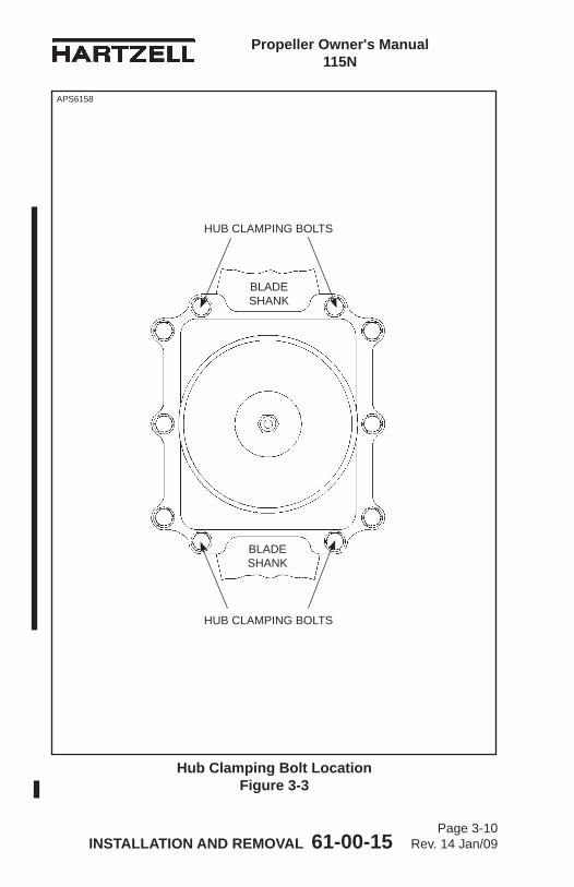
Propeller Owner's Manual 115N
INSTALLATION AND REMOVAL 61-00-15 Page 3-10
Rev. 14 Jan/09
Hub Clamping Bolt Location Figure 3-3
APS6158
HUB CLAMPING BOLTS
HUB CLAMPING BOLTS
BLADE SHANK
BLADE SHANK
Propeller Owner's Manual 115N
INSTALLATION AND REMOVAL 61-00-15 Page 3-11
Rev. 17 Jul/12
(a) If the air pressure loss is less than 10 percent of the specified pressure, reservice the propeller.
(b) If the air pressure loss is greater than 10 percent of the specified pressure, repair the propeller. This repair must be performed at an appropriately licensed repair facility.
3. Spinner Pre-InstallationA. General
(1) The spinner support must be mounted before the propeller can be installed. The spinner will mount either to a bulkhead installed on the propeller hub, or, on some Lycoming engine installations, to an adapter attached to the starter ring gear. Follow the applicable directions in this section.
(2) Refer to Figure 3-3. Remove the nuts from the hub clamping bolts that are located on either side of the blade shank. The remaining nuts/bolts should not be disturbed. Do not remove the bolts.
(3) Refer to Figure 3-3. The spinner may be supplied with long hub clamping bolts. If the bolts were supplied with the spinner, remove the bolts on either side of the blade shank and replace them with the bolts supplied with the spinner. The supplied hub clamping bolts will be longer than those removed from the hub.NOTE: Depending upon the installation, the propeller
hub may have been shipped from the factory with the longer hub clamping bolts installed. In this case, the hub clamping bolts will not be supplied with the spinner.
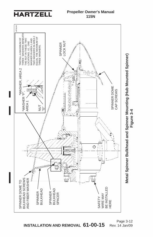
Propeller Owner's Manual 115N
INSTALLATION AND REMOVAL 61-00-15 Page 3-12
Rev. 14 Jan/09
Met
al S
pinn
er B
ulkh
ead
and
Spin
ner M
ount
ing
(Hub
Mou
nted
Spi
nner
) Fi
gure
3-4
SP
INN
ER
B
ULK
HE
AD
SP
INN
ER
DO
ME
TO
B
ULK
HE
AD
SC
RE
WS
A
ND
FIB
ER
WA
SH
ER
SP
INN
ER
DO
ME
C
AP
SC
RE
WS
SA
FETY
W
IRE
MAY
B
E IN
STA
LLE
D
HE
RE
AP
S61
46
SP
INN
ER
B
ULK
HE
AD
S
PAC
ER
SP
INN
ER
LO
CK
NU
T
NU
T “G
”
*WA
SH
ER
, AR
EA
2*W
AS
HE
R “F
”, A
RE
A 1
*IN
STA
LL A
MA
XIM
UM
OF
THR
EE
WA
SH
ER
S B
EN
EAT
H
THE
NU
T IN
TH
ES
E T
WO
LO
CAT
ION
S, I
.E.,
ON
E
WA
SH
ER
IN A
RE
A 1
AN
D
TWO
WA
SH
ER
S IN
AR
EA
2 E
QU
AL
THE
MA
XIM
UM
OF
THR
EE
WA
SH
ER
S.
Propeller Owner's Manual 115N
INSTALLATION AND REMOVAL 61-00-15 Page 3-13
Rev. 17 Jul/12
B. Installation of a Metal Spinner Bulkhead on the Propeller Hub
CAUTION: INSTRUCTIONS AND PROCEDURES IN THIS SECTION MAY INVOLVE PROPELLER CRITICAL PARTS. REFER TO THE INTRODUCTION CHAPTER OF THIS MANUAL FOR INFORMATION ABOUT PROPELLER CRITICAL PARTS. REFER TO THE ILLUSTRATED PARTS LIST CHAPTER OF THE APPLICABLE OVERHAUL MANUAL(S) FOR THE IDENTIFICATION OF SPECIFIC PROPELLER CRITICAL PARTS.
(1) Refer to Figure 3-4. Put the spinner bulkhead spacers on the hub clamping bolts. Install the spinner bulkhead over the installed spacers on the hub clamping bolts.
CAUTION: A MINIMUM OF ONE THREAD OF THE HUB CLAMPING BOLT MUST BE VISIBLE AFTER THE SPINNER MOUNTING NUT IS INSTALLED.
(2) When the spinner bulkhead is installed, there must be no less than one thread of the hub clamping bolt exposed beyond the spinner mounting nut. A total of three washers in two areas may be installed beneath the spinner mounting nut to achieve this result. On some installations, it may be necessary to install spacers and one or more washers beneath the head of the bolt in order to avoid interference with aircraft cowling.(a) Additional washers (as many as four) may have
been used during assembly of the propeller for hub clamping purposes.
Description Part Number
Flat Washer “F” B-3824-0663Spinner Mounting Nut “G” B-3599
Metal Spinner Bulkhead Mounting Hardware Table 3-2
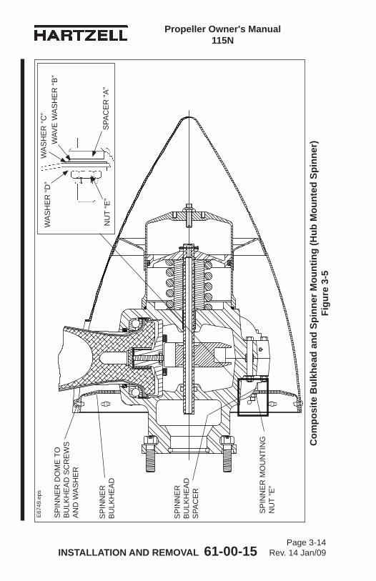
Propeller Owner's Manual 115N
INSTALLATION AND REMOVAL 61-00-15 Page 3-14
Rev. 14 Jan/09
Com
posi
te B
ulkh
ead
and
Spin
ner M
ount
ing
(Hub
Mou
nted
Spi
nner
) Fi
gure
3-5
SP
INN
ER
B
ULK
HE
AD
SP
INN
ER
B
ULK
HE
AD
S
PAC
ER
SP
INN
ER
MO
UN
TIN
G
NU
T ”E
”
SP
INN
ER
DO
ME
TO
B
ULK
HE
AD
SC
RE
WS
A
ND
WA
SH
ER
E67
49.e
ps
NU
T “E
”S
PAC
ER
“A”
WA
SH
ER
“D”
WAV
E W
AS
HE
R “B
” W
AS
HE
R “C
”
Propeller Owner's Manual 115N
INSTALLATION AND REMOVAL 61-00-15 Page 3-15
Rev. 17 Jul/12
1 Use the quantity of washers required when installing the bulkhead for correct spinner position, refer to Figure 3-4.
2 After the correct installation of the spinner, any remaining washers may be discarded.
(5) Install at least one flat washer “F” and a new self-locking spinner mounting nut “G” on each of the hub clamping bolts used to mount the spinner bulkhead. Refer To Table 3-2.
(6) Torque the nuts in accordance with Table 3-1 and Figure 3-1.
C. Installation of a Composite Spinner Bulkhead on a Propeller Hub - Refer to Table 3-3 and Figure 3-5
CAUTION: INSTRUCTIONS AND PROCEDURES IN THIS SECTION MAY INVOLVE PROPELLER CRITICAL PARTS. REFER TO THE INTRODUCTION CHAPTER OF THIS MANUAL FOR INFORMATION ABOUT PROPELLER CRITICAL PARTS. REFER TO THE ILLUSTRATED PARTS LIST CHAPTER OF THE APPLICABLE OVERHAUL MANUAL(S) FOR THE IDENTIFICATION OF SPECIFIC PROPELLER CRITICAL PARTS.
(1) Put a spinner bulkhead spacer “A”, wave washer “B”, and washer “C” on each of the hub clamping bolts.
Description Part Number
Spinner Bulkhead Spacer “A” B-7424-1
Wave Washer “B” B-7425Washer “C” B-3834-0832Flat Washer “D” B-7423Spinner Mounting Nut “E” B-3599
Composite Spinner Bulkhead Mounting Hardware Table 3-3
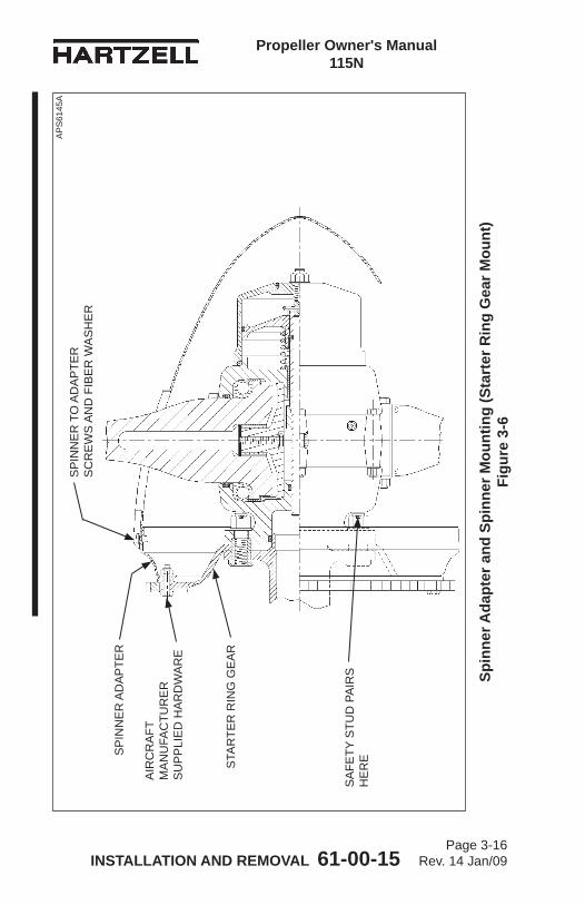
Propeller Owner's Manual 115N
INSTALLATION AND REMOVAL 61-00-15 Page 3-16
Rev. 14 Jan/09
Spin
ner A
dapt
er a
nd S
pinn
er M
ount
ing
(Sta
rter
Rin
g G
ear M
ount
) Fi
gure
3-6
SP
INN
ER
AD
AP
TER
STA
RTE
R R
ING
GE
AR
AIR
CR
AFT
M
AN
UFA
CTU
RE
R
SU
PP
LIE
D H
AR
DW
AR
E
SP
INN
ER
TO
AD
AP
TER
S
CR
EW
S A
ND
FIB
ER
WA
SH
ER
SA
FETY
STU
D P
AIR
S
HE
RE
AP
S61
45A
Propeller Owner's Manual 115N
INSTALLATION AND REMOVAL 61-00-15 Page 3-17
Rev. 17 Jul/12
(2) Install the spinner bulkhead over the installed spacers “A”, wave washers “B”, and washers “C” on the hub clamping bolts.
(3) Install a flat washer “D” and a new self-locking spinner mounting nut “E” on each of the hub clamping bolts used to mount the spinner bulkhead.
CAUTION: A MINIMUM OF ONE THREAD OF THE HUB CLAMPING BOLT MUST BE VISIBLE AFTER THE SPINNER MOUNTING NUT IS INSTALLED.
(a) When the spinner bulkhead is installed, there must be no less than one thread of the hub clamping bolt exposed beyond the spinner mounting nut “E”.
(4) Torque each spinner mounting nut “E” in accordance with Table 3-1 and Figure 3-1.
D. Spinner Adapter to Starter Ring Gear Installation
CAUTION: INSTALL SPINNER ADAPTER BOLTS SO THAT THE BOLT HEADS ARE AT THE REAR OF THE STARTER RING GEAR AS INDICATED IN FIGURE 3-6. BOLTS INSTALLED INCORRECTLY MAY DAMAGE ENGINE COMPONENTS.
(1) See Figure 3-6. Install the spinner adapter ring to the starter ring gear using the hardware supplied by the airframe manufacturer. Torque the bolts as specified by the airframe manufacturer.
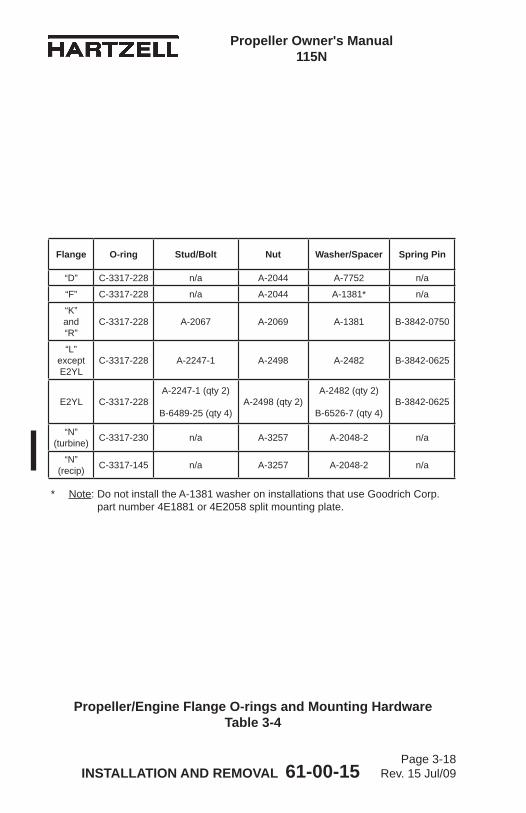
Propeller Owner's Manual 115N
INSTALLATION AND REMOVAL 61-00-15 Page 3-18
Rev. 15 Jul/09
Propeller/Engine Flange O-rings and Mounting Hardware Table 3-4
* Note: Do not install the A-1381 washer on installations that use Goodrich Corp. part number 4E1881 or 4E2058 split mounting plate.
Flange O-ring Stud/Bolt Nut Washer/Spacer Spring Pin
“D” C-3317-228 n/a A-2044 A-7752 n/a
“F” C-3317-228 n/a A-2044 A-1381* n/a
“K”and“R”
C-3317-228 A-2067 A-2069 A-1381 B-3842-0750
“L”exceptE2YL
C-3317-228 A-2247-1 A-2498 A-2482 B-3842-0625
E2YL C-3317-228A-2247-1 (qty 2)
B-6489-25 (qty 4)A-2498 (qty 2)
A-2482 (qty 2)
B-6526-7 (qty 4)B-3842-0625
“N”(turbine) C-3317-230 n/a A-3257 A-2048-2 n/a
“N”(recip) C-3317-145 n/a A-3257 A-2048-2 n/a
Propeller Owner's Manual 115N
INSTALLATION AND REMOVAL 61-00-15 Page 3-19
Rev. 14 Jan/09
WARNING: FAILURE TO FOLLOW THESE INSTALLATION INSTRUCTIONS MAY LEAD TO PROPELLER DAMAGE, ENGINE DAMAGE, OR PROPELLER FAILURE, WHICH MAY RESULT IN DEATH, SERIOUS BODILY INJURY, AND/OR SUBSTANTIAL PROPERTY DAMAGE. UNUSUAL OR ABNORMAL VIBRATION DEMANDS IMMEDIATE INSPECTION FOR IMPROPER PROPELLER INSTALLATION. PROPELLER SEPARATION MAY OR MAY NOT BE PROCEEDED BY VIBRATION.
4. Propeller Installation
CAUTION: SOME STEEL HUB PROPELLERS INCORPORATE A PHENOLIC SPACER BETWEEN THE PROPELLER AND ENGINE-MOUNTING FLANGE. WHEN INSTALLING AN ALUMINUM HUB PROPELLER, THIS SPACER IS TO BE DISCARDED. THE ALUMINUM HUB PROPELLER MOUNTING O-RING IS LOCATED ON THE INSIDE DIAMETER OF THE PROPELLER HUB. THERE SHOULD NOT BE AN O-RING ON THE ENGINE FLANGE WHEN INSTALLING AN ALUMINUM HUB PROPELLER.
A. Flange Description(1) Compact propellers are manufactured with six basic hub
mounting flange designs. The flange type designators are D, F, K, L, N, or R.
(2) The flange type used on a particular propeller installation is indicated in the propeller model stamped on the hub. For example, HC-C2YF-4A indicates an “F” flange.
(3) Refer to Aluminum Hub Propeller Model Identification in the Description and Operation Chapter of this manual for description of each flange type. Sample flanges are also shown in Figures 3-8 and 3-9.
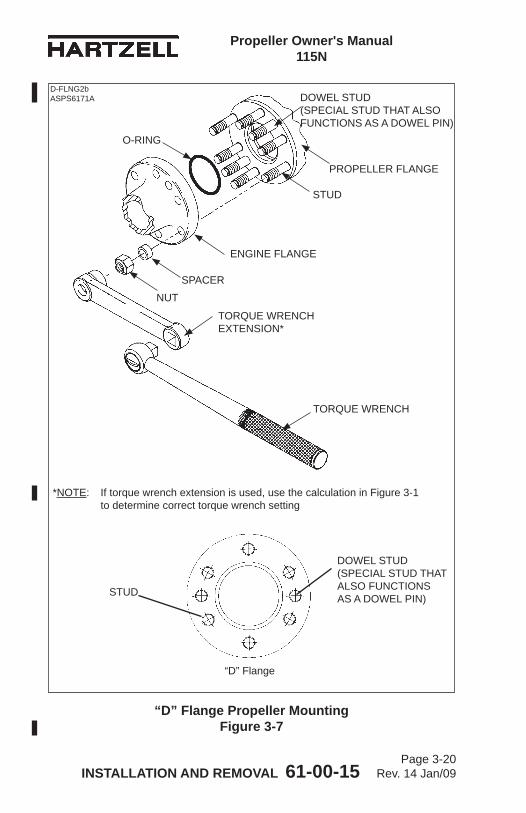
Propeller Owner's Manual 115N
INSTALLATION AND REMOVAL 61-00-15 Page 3-20
Rev. 14 Jan/09
“D” Flange Propeller Mounting Figure 3-7
O-RING
PROPELLER FLANGE
ENGINE FLANGE
NUT
STUD
“D” Flange
*NOTE: If torque wrench extension is used, use the calculation in Figure 3-1 to determine correct torque wrench setting
TORQUE WRENCH
TORQUE WRENCH EXTENSION*
SPACER
DOWEL STUD (SPECIAL STUD THAT ALSO FUNCTIONS AS A DOWEL PIN)
STUD
DOWEL STUD (SPECIAL STUD THAT ALSO FUNCTIONS AS A DOWEL PIN)
D-FLNG2b ASPS6171A
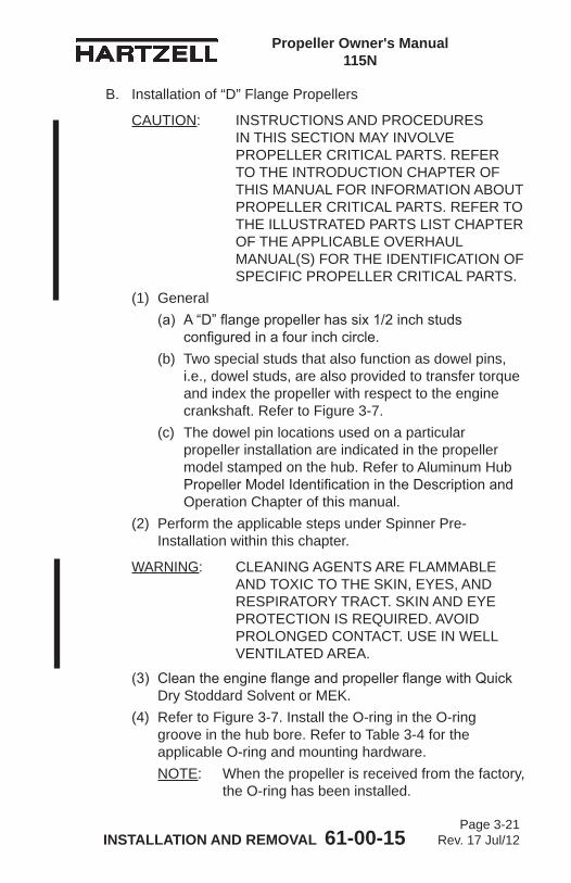
Propeller Owner's Manual 115N
INSTALLATION AND REMOVAL 61-00-15 Page 3-21
Rev. 17 Jul/12
B. Installation of “D” Flange Propellers
CAUTION: INSTRUCTIONS AND PROCEDURES IN THIS SECTION MAY INVOLVE PROPELLER CRITICAL PARTS. REFER TO THE INTRODUCTION CHAPTER OF THIS MANUAL FOR INFORMATION ABOUT PROPELLER CRITICAL PARTS. REFER TO THE ILLUSTRATED PARTS LIST CHAPTER OF THE APPLICABLE OVERHAUL MANUAL(S) FOR THE IDENTIFICATION OF SPECIFIC PROPELLER CRITICAL PARTS.
(1) General(a) A “D” flange propeller has six 1/2 inch studs
configured in a four inch circle. (b) Two special studs that also function as dowel pins,
i.e., dowel studs, are also provided to transfer torque and index the propeller with respect to the engine crankshaft. Refer to Figure 3-7.
(c) The dowel pin locations used on a particular propeller installation are indicated in the propeller model stamped on the hub. Refer to Aluminum Hub Propeller Model Identification in the Description and Operation Chapter of this manual.
(2) Perform the applicable steps under Spinner Pre-Installation within this chapter.
WARNING: CLEANING AGENTS ARE FLAMMABLE AND TOXIC TO THE SKIN, EYES, AND RESPIRATORY TRACT. SKIN AND EYE PROTECTION IS REQUIRED. AVOID PROLONGED CONTACT. USE IN WELL VENTILATED AREA.
(3) Clean the engine flange and propeller flange with Quick Dry Stoddard Solvent or MEK.
(4) Refer to Figure 3-7. Install the O-ring in the O-ring groove in the hub bore. Refer to Table 3-4 for the applicable O-ring and mounting hardware.NOTE: When the propeller is received from the factory,
the O-ring has been installed.

Propeller Owner's Manual 115N
INSTALLATION AND REMOVAL 61-00-15 Page 3-22
Rev. 14 Jan/09
WARNING: MAKE SURE THAT ANY EQUIPMENT USED TO INSTALL THE PROPELLER IS RATED UP TO 800 LBS. (363 KG) TO SUPPORT THE WEIGHT OF THE PROPELLER ASSEMBLY DURING INSTALLATION. ONE PERSON MUST NEVER ATTEMPT TO INSTALL AN UNSUPPORTED PROPELLER BY HIMSELF, REGARDLESS OF THE SIZE OR WEIGHT OF THE PROPELLER. MANUALLY LIFTING THE PROPELLER ONTO THE ENGINE CAN RESULT IN PERSONAL INJURY.
CAUTION 1: A PROPELLER MUST BE CORRECTLY SUPPORTED DURING INSTALLATION ON THE ENGINE. AVOID ANY ROCKING OR SHIFTING OF THE PROPELLER WHEN IT IS PARTIALLY ENGAGED WITH THE ENGINE. ROCKING OF THE PROPELLER DURING PROPELLER INSTALLATION CAN DAMAGE THE PROPELLER HUB MOUNTING FACE, CAUSING ACTUATION OIL LEAKAGE OR DAMAGE THAT MAY SCRAP THE HUB. HUB DAMAGE CAN ALSO INTRODUCE METAL INTO THE PROPELLER OIL ACTUATION SYSTEM, WHICH COULD POSSIBLY DAMAGE THE ENGINE.
CAUTION 2: WHEN INSTALLING THE PROPELLER ON THE AIRCRAFT, DO NOT DAMAGE THE ICE PROTECTION SYSTEM COMPONENTS, IF APPLICABLE.
(5) With a suitable support, such as a crane hoist or similar equipment, carefully move the propeller assembly to the aircraft engine mounting flange in preparation for installation.
Propeller Owner's Manual 115N
INSTALLATION AND REMOVAL 61-00-15 Page 3-23
Rev. 17 Jul/12
(6) Install the propeller on the engine flange. Make certain to align the dowel studs in the propeller flange with the corresponding holes in the engine mounting flange.(a) The propeller may be installed on the engine
flange in a given position, or 180 degrees from that position. Check the engine and airframe manuals to determine if either manual specifies a propeller mounting position.
CAUTION 1: MOUNTING HARDWARE MUST BE CLEAN AND DRY TO PREVENT EXCESSIVE PRELOAD OF THE MOUNTING FLANGE.
CAUTION 2: TIGHTEN NUTS EVENLY TO AVOID HUB DAMAGE.
(7) Install the 1/2 inch propeller mounting nuts (dry) with spacers. Refer to Table 3-4.(a) If the propeller is removed between overhaul
intervals, mounting nuts may be reused if they are not damaged or corroded.
(8) Torque the 1/2 inch propeller mounting nuts (dry) in accordance with Table 3-1 and Figure 3-1. Safety wire the studs in pairs (if required by the aircraft maintenance manual) at the rear of the propeller mounting flange. Refer to Figure 3-4.
(9) If the propeller is equipped with an ice protection system that uses components supplied by Hartzell Propeller Inc., applicable instructions and technical information for the components supplied by Hartzell Propeller Inc. can be found in the following publications available on the Hartzell Propeller Inc. website at www.hartzellprop.com: (a) Hartzell Propeller Inc. Manual 180 (30-61-80) -
Propeller Ice Protection System Manual(b) Hartzell Propeller Inc. Manual 181 (30-60-81)
- Propeller Ice Protection System Component Maintenance Manual
Propeller Owner's Manual 115N
INSTALLATION AND REMOVAL 61-00-15 Page 3-24
Rev. 17 Jul/12
(c) Hartzell Propeller Inc. Manual 182 (61-12-82) - Propeller Electrical De-ice Boot Removal and Installation Manual
(d) Hartzell Propeller Inc. Manual 183 (61-12-83) - Propeller Anti-icing Boot Removal and Installation Manual
(10) Propeller ice protection system components not supplied by Hartzell Propeller Inc. are controlled by the applicable TC or STC holder’s Instructions for Continued Airworthiness (ICA).
(11) Install the propeller spinner dome in accordance with the section “Spinner Installation” in this chapter.

Propeller Owner's Manual 115N
INSTALLATION AND REMOVAL 61-00-15 Page 3-25
Rev. 14 Jan/09
(This page is intentionally blank.)
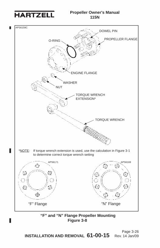
Propeller Owner's Manual 115N
INSTALLATION AND REMOVAL 61-00-15 Page 3-26
Rev. 14 Jan/09
“F” and “N” Flange Propeller Mounting Figure 3-8
O-RING PROPELLER FLANGE
ENGINE FLANGE
DOWEL PINAPS6159C
“F” Flange “N” Flange
*NOTE: If torque wrench extension is used, use the calculation in Figure 3-1 to determine correct torque wrench setting
APS6171 APS6169
TORQUE WRENCH
TORQUE WRENCH EXTENSION*
NUTWASHER
Propeller Owner's Manual 115N
INSTALLATION AND REMOVAL 61-00-15 Page 3-27
Rev. 17 Jul/12
C. Installation of “F” Flange Propellers
CAUTION: INSTRUCTIONS AND PROCEDURES IN THIS SECTION MAY INVOLVE PROPELLER CRITICAL PARTS. REFER TO THE INTRODUCTION CHAPTER OF THIS MANUAL FOR INFORMATION ABOUT PROPELLER CRITICAL PARTS. REFER TO THE ILLUSTRATED PARTS LIST CHAPTER OF THE APPLICABLE OVERHAUL MANUAL(S) FOR THE IDENTIFICATION OF SPECIFIC PROPELLER CRITICAL PARTS.
(1) General(a) An “F” flange propeller has six 1/2 inch studs
configured in a four inch circle. (b) Two dowel pins are also provided to transfer torque
and index the propeller with respect to the engine crankshaft. Refer to Figure 3-8.
(c) The dowel pin locations used on a particular propeller installation are indicated in the propeller model stamped on the hub. Refer to Aluminum Hub Propeller Model Identification in the Description and Operation Chapter of this manual.
(2) Perform the applicable steps under Spinner Pre-Installation within this chapter.
WARNING: CLEANING AGENTS ARE FLAMMABLE AND TOXIC TO THE SKIN, EYES, AND RESPIRATORY TRACT. SKIN AND EYE PROTECTION IS REQUIRED. AVOID PROLONGED CONTACT. USE IN WELL VENTILATED AREA.
(3) Clean the engine flange and propeller flange with Quick Dry Stoddard Solvent or MEK.
(4) Refer to Figure 3-8. Install the O-ring in the O-ring groove in the hub bore. Refer to Table 3-4 for the applicable O-ring and mounting hardware.NOTE: When the propeller is received from the
factory, the O-ring has been installed.
Propeller Owner's Manual 115N
INSTALLATION AND REMOVAL 61-00-15 Page 3-28
Rev. 14 Jan/09
WARNING: MAKE SURE THAT ANY EQUIPMENT USED TO INSTALL THE PROPELLER IS RATED UP TO 800 LBS. (363 KG) TO SUPPORT THE WEIGHT OF THE PROPELLER ASSEMBLY DURING INSTALLATION. ONE PERSON MUST NEVER ATTEMPT TO INSTALL AN UNSUPPORTED PROPELLER BY HIMSELF, REGARDLESS OF THE SIZE OR WEIGHT OF THE PROPELLER. MANUALLY LIFTING THE PROPELLER ONTO THE ENGINE CAN RESULT IN PERSONAL INJURY.
CAUTION 1: A PROPELLER MUST BE CORRECTLY SUPPORTED DURING INSTALLATION ON THE ENGINE. AVOID ANY ROCKING OR SHIFTING OF THE PROPELLER WHEN IT IS PARTIALLY ENGAGED WITH THE ENGINE. ROCKING OF THE PROPELLER DURING PROPELLER INSTALLATION CAN DAMAGE THE PROPELLER HUB MOUNTING FACE, CAUSING ACTUATION OIL LEAKAGE OR DAMAGE THAT MAY SCRAP THE HUB. HUB DAMAGE CAN ALSO INTRODUCE METAL INTO THE PROPELLER OIL ACTUATION SYSTEM, WHICH COULD POSSIBLY DAMAGE THE ENGINE.
CAUTION 2: WHEN INSTALLING THE PROPELLER ON THE AIRCRAFT, DO NOT DAMAGE THE ICE PROTECTION SYSTEM COMPONENTS, IF APPLICABLE.
(5) With a suitable support, such as a crane hoist or similar equipment, carefully move the propeller assembly to the aircraft engine mounting flange in preparation for installation.
(6) Install the propeller on the engine flange. Make certain to align the dowel pins in the propeller flange with the corresponding holes in the engine mounting flange.
Propeller Owner's Manual 115N
INSTALLATION AND REMOVAL 61-00-15 Page 3-29
Rev. 17 Jul/12
(a) The propeller may be installed on the engine flange in a given position, or 180 degrees from that position. Check the engine and airframe manuals to determine if either manual specifies a propeller mounting position.
CAUTION 1: MOUNTING HARDWARE MUST BE CLEAN AND DRY TO PREVENT EXCESSIVE PRELOAD OF THE MOUNTING FLANGE.
CAUTION 2: TIGHTEN NUTS EVENLY TO AVOID HUB DAMAGE.
(7) Install the 1/2 inch propeller mounting nuts (dry) with washers. Refer to Table 3-4.(a) If the propeller is removed between overhaul
intervals, mounting nuts may be reused if they are not damaged or corroded.
(8) Torque the 1/2 inch propeller mounting nuts (dry) in accordance with Table 3-1, Figure 3-1 and Figure 3-2. Safety wire the studs in pairs (if required by the aircraft maintenance manual) at the rear of the propeller mounting flange. Refer to Figure 3-4.
(9) If the propeller is equipped with an ice protection system that uses components supplied by Hartzell Propeller Inc., applicable instructions and technical information for the components supplied by Hartzell Propeller Inc. can be found in the following publications available on the Hartzell Propeller Inc. website at www.hartzellprop.com: (a) Hartzell Propeller Inc. Manual 180 (30-61-80) -
Propeller Ice Protection System Manual(b) Hartzell Propeller Inc. Manual 181 (30-60-81)
- Propeller Ice Protection System Component Maintenance Manual
(c) Hartzell Propeller Inc. Manual 182 (61-12-82) - Propeller Electrical De-ice Boot Removal and Installation Manual
(d) Hartzell Propeller Inc. Manual 183 (61-12-83) - Propeller Anti-icing Boot Removal and Installation Manual
Propeller Owner's Manual 115N
INSTALLATION AND REMOVAL 61-00-15 Page 3-30
Rev. 17 Jul/12
(10) Propeller ice protection system components not supplied by Hartzell Propeller Inc. are controlled by the applicable TC or STC holder’s Instructions for Continued Airworthiness (ICA).
(11) Install the propeller spinner dome in accordance with the section “Spinner Installation” in this chapter.
D. Installation of “N” Flange Propellers(1) General
(a) An “N” flange propeller has eight 9/16 inch studs configured in a 4.25 inch circle.
(b) Two dowel pins are also provided to transfer torque and index the propeller with respect to the engine crankshaft. Refer to Figure 3-8.
(c) The dowel pin locations used on a particular propeller installation are indicated in the propeller model stamped on the hub. Refer to Aluminum Hub Propeller Model Identification in the Description and Operation Chapter of this manual.
(2) Perform the applicable steps under Spinner Pre-Installation within this chapter.
WARNING: CLEANING AGENTS ARE FLAMMABLE AND TOXIC TO THE SKIN, EYES, AND RESPIRATORY TRACT. SKIN AND EYE PROTECTION IS REQUIRED. AVOID PROLONGED CONTACT. USE IN WELL VENTILATED AREA.
(3) Clean the engine flange and propeller flange with Quick Dry Stoddard Solvent or MEK.
(4) Refer to Figure 3-8. Install the O-ring on the engine flange. Refer to Table 3-4 for the applicable O-ring and mounting hardware.NOTE: When the propeller is received from the
factory, the O-ring has been installed.
Propeller Owner's Manual 115N
INSTALLATION AND REMOVAL 61-00-15 Page 3-31
Rev. 14 Jan/09
WARNING: MAKE SURE THAT ANY EQUIPMENT USED TO INSTALL THE PROPELLER IS RATED UP TO 800 LBS. (363 KG) TO SUPPORT THE WEIGHT OF THE PROPELLER ASSEMBLY DURING INSTALLATION. ONE PERSON MUST NEVER ATTEMPT TO INSTALL AN UNSUPPORTED PROPELLER BY HIMSELF, REGARDLESS OF THE SIZE OR WEIGHT OF THE PROPELLER. MANUALLY LIFTING THE PROPELLER ONTO THE ENGINE CAN RESULT IN PERSONAL INJURY.
CAUTION 1: A PROPELLER MUST BE CORRECTLY SUPPORTED DURING INSTALLATION ON THE ENGINE. AVOID ANY ROCKING OR SHIFTING OF THE PROPELLER WHEN IT IS PARTIALLY ENGAGED WITH THE ENGINE. ROCKING OF THE PROPELLER DURING PROPELLER INSTALLATION CAN DAMAGE THE PROPELLER HUB MOUNTING FACE, CAUSING ACTUATION OIL LEAKAGE OR DAMAGE THAT MAY SCRAP THE HUB. HUB DAMAGE CAN ALSO INTRODUCE METAL INTO THE PROPELLER OIL ACTUATION SYSTEM, WHICH COULD POSSIBLY DAMAGE THE ENGINE.
CAUTION 2: WHEN INSTALLING THE PROPELLER ON THE AIRCRAFT, DO NOT DAMAGE THE ICE PROTECTION SYSTEM COMPONENTS, IF APPLICABLE.
(5) With a suitable support, such as a crane hoist or similar equipment, carefully move the propeller assembly to the aircraft engine mounting flange in preparation for installation.
Propeller Owner's Manual 115N
INSTALLATION AND REMOVAL 61-00-15 Page 3-32
Rev. 17 Jul/12
(6) Install the propeller on the engine flange. Make certain to align the dowel pins in the propeller flange with the corresponding holes in the engine mounting flange.(a) The propeller may be installed on the engine flange
in a given position, or 180 degrees from that position. Check the engine and airframe manuals to determine if either manual specifies a propeller mounting position.
CAUTION 1: MOUNTING HARDWARE MUST BE CLEAN AND DRY TO PREVENT EXCESSIVE PRELOAD OF THE MOUNTING FLANGE.
CAUTION 2: TIGHTEN NUTS EVENLY TO AVOID HUB DAMAGE.
(7) Install the 9/16 inch propeller mounting nuts (dry) with washers. Refer to Table 3-4.(a) If the propeller is removed between overhaul intervals,
mounting nuts may be reused if they are not damaged or corroded.
(8) Torque the 9/16 inch propeller mounting nuts (dry) in accordance with Table 3-1 and Figure 3-1. Safety wire the studs in pairs (if required by the aircraft maintenance manual) at the rear of the propeller mounting flange. Refer to Figure 3-4.
(9) If the propeller is equipped with an ice protection system that uses components supplied by Hartzell Propeller Inc., applicable instructions and technical information for the components supplied by Hartzell Propeller Inc. can be found in the following publications available on the Hartzell Propeller Inc. website at www.hartzellprop.com: (a) Hartzell Propeller Inc. Manual 180 (30-61-80) -
Propeller Ice Protection System Manual(b) Hartzell Propeller Inc. Manual 181 (30-60-81)
- Propeller Ice Protection System Component Maintenance Manual
(c) Hartzell Propeller Inc. Manual 182 (61-12-82) - Propeller Electrical De-ice Boot Removal and Installation Manual
(d) Hartzell Propeller Inc. Manual 183 (61-12-83) - Propeller Anti-icing Boot Removal and Installation Manual
Propeller Owner's Manual 115N
INSTALLATION AND REMOVAL 61-00-15 Page 3-33
Rev. 14 Jan/09
(10) Propeller ice protection system components not supplied by Hartzell Propeller Inc. are controlled by the applicable TC or STC holder’s Instructions for Continued Airworthiness (ICA).
(11) Install the propeller spinner dome in accordance with the section “Spinner Installation” in this chapter.
Propeller Owner's Manual 115N
INSTALLATION AND REMOVAL 61-00-15 Page 3-34
Rev. 14 Jan/09
“L,” “K,” and “R” Flange Propeller Mounting - Figure 3-9
TORQUE WRENCH
APS6160D
“L” Flange “K” Flange “R” Flange
*NOTE: If torque wrench extension is used, use the calculation in Figure 3-1 to determine correct torque wrench setting
APS6170 APS6168 APS6172
PROPELLER FLANGE
STARTER RING GEAR
ENGINE FLANGE
O-RING (INSTALLED
IN HUB)
WASHER
TORQUE WRENCH EXTENSION*
NUTSPRING PIN
Propeller Owner's Manual 115N
INSTALLATION AND REMOVAL 61-00-15 Page 3-35
Rev. 17 Jul/12
E. Installation of “L” Flange Propellers (except model HC-E2YL-[ ])
CAUTION: INSTRUCTIONS AND PROCEDURES IN THIS SECTION MAY INVOLVE PROPELLER CRITICAL PARTS. REFER TO THE INTRODUCTION CHAPTER OF THIS MANUAL FOR INFORMATION ABOUT PROPELLER CRITICAL PARTS. REFER TO THE ILLUSTRATED PARTS LIST CHAPTER OF THE APPLICABLE OVERHAUL MANUAL(S) FOR THE IDENTIFICATION OF SPECIFIC PROPELLER CRITICAL PARTS.
(1) General(a) An “L” flange is an SAE No. 2 flange with six 7/16 inch
studs configured in a 4.75 inch circle. (b) Four drive bushings transfer torque and index the
propeller with respect to the engine crankshaft. The bushings are located on the engine flange and fit into openings on the propeller flange. Refer to Figure 3-9.
(c) The bushing locations used on a particular propeller installation are indicated in the propeller model stamped on the hub. Refer to Aluminum Hub Propeller Model Identification in the Description and Operation chapter of this manual.
(2) Perform the appropriate steps in the Spinner Pre-Installation section in this chapter.
WARNING: CLEANING AGENTS ARE FLAMMABLE AND TOXIC TO THE SKIN, EYES, AND RESPIRATORY TRACT. SKIN AND EYE PROTECTION ARE REQUIRED. AVOID PROLONGED CONTACT. USE IN WELL VENTILATED AREA.
(3) Clean the engine flange and propeller flange with Quick Dry Stoddard Solvent or MEK.
(4) Refer to Figure 3-9. Install the O-ring in the O-ring groove in the rear of the hub. Refer to Table 3-4 for the applicable O-ring and mounting hardware.NOTE: When the propeller is received from the factory,
the O-ring has been installed.
Propeller Owner's Manual 115N
INSTALLATION AND REMOVAL 61-00-15 Page 3-36
Rev. 14 Jan/09
WARNING: MAKE SURE THAT ANY EQUIPMENT USED TO INSTALL THE PROPELLER IS RATED UP TO 800 LBS. (363 KG) TO SUPPORT THE WEIGHT OF THE PROPELLER ASSEMBLY DURING INSTALLATION. ONE PERSON MUST NEVER ATTEMPT TO INSTALL AN UNSUPPORTED PROPELLER BY HIMSELF, REGARDLESS OF THE SIZE OR WEIGHT OF THE PROPELLER. MANUALLY LIFTING THE PROPELLER ONTO THE ENGINE CAN RESULT IN PERSONAL INJURY.
CAUTION 1: A PROPELLER MUST BE CORRECTLY SUPPORTED DURING INSTALLATION ON THE ENGINE. AVOID ANY ROCKING OR SHIFTING OF THE PROPELLER WHEN IT IS PARTIALLY ENGAGED WITH THE ENGINE. ROCKING OF THE PROPELLER DURING PROPELLER INSTALLATION CAN DAMAGE THE PROPELLER HUB MOUNTING FACE, CAUSING ACTUATION OIL LEAKAGE OR DAMAGE THAT MAY SCRAP THE HUB. HUB DAMAGE CAN ALSO INTRODUCE METAL INTO THE PROPELLER OIL ACTUATION SYSTEM, WHICH COULD POSSIBLY DAMAGE THE ENGINE.
CAUTION 2: WHEN INSTALLING THE PROPELLER ON THE AIRCRAFT, DO NOT DAMAGE THE ICE PROTECTION SYSTEM COMPONENTS, IF APPLICABLE.
(5) With a suitable support, such as a crane hoist or similar equipment, carefully move the propeller assembly to the aircraft engine mounting flange in preparation for installation.
(6) Install the propeller on the engine flange. Align the engine flange bushings with the corresponding holes in the propeller flange.
Propeller Owner's Manual 115N
INSTALLATION AND REMOVAL 61-00-15 Page 3-37
Rev. 17 Jul/12
(a) The propeller may be installed on the engine flange in a given position, or 180 degrees from that position. Check the engine and airframe manuals to determine if either manual specifies a propeller mounting position.
CAUTION 1: MOUNTING HARDWARE MUST BE CLEAN AND DRY TO PREVENT EXCESSIVE PRELOAD OF THE MOUNTING FLANGE.
CAUTION 2: TIGHTEN NUTS EVENLY TO AVOID HUB DAMAGE.
(7) Torque the 7/16 inch propeller mounting studs (dry) in accordance with Table 3-1 and Figure 3-1. Safety wire the studs in pairs (if required by the aircraft maintenance manual) at the rear of the propeller mounting flange. Refer to Figure 3-6.(a) If the propeller is removed between overhaul
intervals, mounting studs may be reused if they are not damaged or corroded.
(8) If the propeller is equipped with an ice protection system that uses components supplied by Hartzell Propeller Inc., applicable instructions and technical information for the components supplied by Hartzell Propeller Inc. can be found in the following publications available on the Hartzell Propeller Inc. website at www.hartzellprop.com: (a) Manual 180 (30-61-80) - Propeller Ice Protection
System Manual(b) Manual 181 (30-60-81) - Propeller Ice Protection
System Component Maintenance Manual(c) Manual 182 (61-12-82) - Propeller Electrical De-ice
Boot Removal and Installation Manual(d) Manual 183 (61-12-83) - Propeller Anti-icing Boot
Removal and Installation Manual(9) Propeller ice protection system components not
supplied by Hartzell Propeller Inc. are controlled by the applicable TC or STC holder’s Instructions for Continued Airworthiness (ICA).
(10) Install the propeller spinner dome in accordance with the section “Spinner Installation” in this chapter.
Propeller Owner's Manual 115N
INSTALLATION AND REMOVAL 61-00-15 Page 3-38
Rev. 17 Jul/12
F. Installation of HC-E2YL-( ) Propellers
CAUTION: INSTRUCTIONS AND PROCEDURES IN THIS SECTION MAY INVOLVE PROPELLER CRITICAL PARTS. REFER TO THE INTRODUCTION CHAPTER OF THIS MANUAL FOR INFORMATION ABOUT PROPELLER CRITICAL PARTS. REFER TO THE ILLUSTRATED PARTS LIST CHAPTER OF THE APPLICABLE OVERHAUL MANUAL(S) FOR THE IDENTIFICATION OF SPECIFIC PROPELLER CRITICAL PARTS.
(1) General(a) An E2YL flange has four 7/16 inch studs and two
7/16 inch bolts configured in a 4.75 inch circle.(b) Four drive bushings transfer torque and index the
propeller with respect to the engine crankshaft. The bushings are located on the engine flange and fit into openings on the propeller flange. Refer to Figure 3-7.
(c) The bushing location used on this propeller installation is indicated in the propeller model. Refer to Aluminum Hub Propeller Model Identification in the Description and Operation chapter of this manual.
(2) Perform the applicable steps in the Spinner Pre-installation section in this chapter.
WARNING: CLEANING AGENTS ARE FLAMMABLE AND TOXIC TO THE SKIN, EYES, AND RESPIRATORY TRACT. SKIN AND EYE PROTECTION ARE REQUIRED. AVOID PROLONGED CONTACT. USE IN WELL VENTILATED AREA.
(3) Clean the engine flange and propeller flange with Quick Dry Stoddard Solvent or MEK.
Propeller Owner's Manual 115N
INSTALLATION AND REMOVAL 61-00-15 Page 3-39
Rev. 17 Jul/12
(4) Refer to Figure 3-9. Install the O-ring in the O-ring groove in the rear of the hub. Refer to Table 3-4 for the applicable O-ring and mounting hardware.NOTE: When the propeller is received from the
factory, the O-ring has been installed.
WARNING: MAKE SURE THAT ANY EQUIPMENT USED TO INSTALL THE PROPELLER IS RATED UP TO 800 LBS. (363 KG) TO SUPPORT THE WEIGHT OF THE PROPELLER ASSEMBLY DURING INSTALLATION. ONE PERSON MUST NEVER ATTEMPT TO INSTALL AN UNSUPPORTED PROPELLER BY HIMSELF, REGARDLESS OF THE SIZE OR WEIGHT OF THE PROPELLER. MANUALLY LIFTING THE PROPELLER ONTO THE ENGINE CAN RESULT IN PERSONAL INJURY.
CAUTION 1: A PROPELLER MUST BE CORRECTLY SUPPORTED DURING INSTALLATION ON THE ENGINE. AVOID ANY ROCKING OR SHIFTING OF THE PROPELLER WHEN IT IS PARTIALLY ENGAGED WITH THE ENGINE. ROCKING OF THE PROPELLER DURING PROPELLER INSTALLATION CAN DAMAGE THE PROPELLER HUB MOUNTING FACE, CAUSING ACTUATION OIL LEAKAGE OR DAMAGE THAT MAY SCRAP THE HUB. HUB DAMAGE CAN ALSO INTRODUCE METAL INTO THE PROPELLER OIL ACTUATION SYSTEM, WHICH COULD POSSIBLY DAMAGE THE ENGINE.
Propeller Owner's Manual 115N
INSTALLATION AND REMOVAL 61-00-15 Page 3-40
Rev. 17 Jul/12
CAUTION 2: WHEN INSTALLING THE PROPELLER ON THE AIRCRAFT, DO NOT DAMAGE THE ICE PROTECTION SYSTEM COMPONENTS, IF APPLICABLE.
(5) With a suitable support, such as a crane hoist or similar equipment, carefully move the propeller assembly to the aircraft engine mounting flange in preparation for installation.
(6) Install the propeller on the engine flange. Align the engine flange bushings with the corresponding holes in the propeller flange.(a) The propeller may be installed on the engine
flange in a given position, or 180 degrees from that position. Refer to the engine and airframe manuals to determine if either manual specifies a propeller mounting position.
CAUTION 1: MOUNTING HARDWARE MUST BE CLEAN AND DRY TO PREVENT EXCESSIVE PRELOAD OF THE MOUNTING FLANGE.
CAUTION 2: TIGHTEN NUTS EVENLY TO AVOID HUB DAMAGE.
(7) Install the 7/16 inch propeller mounting bolts (dry) with washers. Refer to Table 3-4.(a) If the propeller is removed between overhaul
intervals, mounting bolts and studs may be reused if they are not damaged or corroded.
(8) Torque the 7/16 inch nuts on the propeller mounting studs (dry) and the 7/16 inch bolts (dry) in accordance with Table 3-1 and Figure 3-1. Safety wire the studs in pairs (if required by the aircraft maintenance manual) at the rear of the propeller mounting flange. Refer to Figure 3-6.
Propeller Owner's Manual 115N
INSTALLATION AND REMOVAL 61-00-15 Page 3-41
Rev. 17 Jul/12
(9) If the propeller is equipped with an ice protection system that uses components supplied by Hartzell Propeller Inc., applicable instructions and technical information for the components supplied by Hartzell Propeller Inc. can be found in the following publications available on the Hartzell Propeller Inc. website at www.hartzellprop.com: (a) Manual 180 (30-61-80) - Propeller Ice Protection
System Manual(b) Manual 181 (30-60-81) - Propeller Ice Protection
System Component Maintenance Manual(c) Manual 182 (61-12-82) - Propeller Electrical De-ice
Boot Removal and Installation Manual(d) Manual 183 (61-12-83) - Propeller Anti-icing Boot
Removal and Installation Manual(10) Propeller ice protection system components not
supplied by Hartzell Propeller Inc. are controlled by the applicable TC or STC holder’s Instructions for Continued Airworthiness (ICA).
(11) Install the propeller spinner dome in accordance with the section “Spinner Installation” in this chapter.
Propeller Owner's Manual 115N
INSTALLATION AND REMOVAL 61-00-15 Page 3-42
Rev. 17 Jul/12
G. Installation of “K” and “R” Flange Propellers
CAUTION: INSTRUCTIONS AND PROCEDURES IN THIS SECTION MAY INVOLVE PROPELLER CRITICAL PARTS. REFER TO THE INTRODUCTION CHAPTER OF THIS MANUAL FOR INFORMATION ABOUT PROPELLER CRITICAL PARTS. REFER TO THE ILLUSTRATED PARTS LIST CHAPTER OF THE APPLICABLE OVERHAUL MANUAL(S) FOR THE IDENTIFICATION OF SPECIFIC PROPELLER CRITICAL PARTS.
(1) General(a) A “K” or “R” flange is an SAE No. 2 flange that has
six 1/2 inch studs configured in a 4.75 inch circle.(b) Four (“K” flange) or five (“R” flange) drive bushings
transfer torque and index the propeller with respect to the engine crankshaft. The bushings are located on the engine flange and fit into counterbored holes on the propeller flange. Refer to Figure 3-9.
(c) An “R” flange propeller may be installed on a “K” engine flange. A “K” flange propeller cannot be installed on an “R” flange engine.
(d) The bushing locations used on a particular propeller installation are indicated in the propeller model stamped on the hub. Refer to Aluminum Hub Propeller Model Identification in the Description and Operation chapter of this manual.
(2) Perform the applicable steps under Spinner Pre-Installation within this chapter.
WARNING: CLEANING AGENTS ARE FLAMMABLE AND TOXIC TO THE SKIN, EYES AND RESPIRATORY TRACT. SKIN AND EYE PROTECTION IS REQUIRED. AVOID PROLONGED CONTACT. USE IN WELL VENTILATED AREA.
(3) Clean the engine flange and propeller flange with Quick Dry Stoddard Solvent or MEK.
Propeller Owner's Manual 115N
INSTALLATION AND REMOVAL 61-00-15 Page 3-43
Rev. 20 Mar/14
(4) See Figure 3-9. Install the O-ring in the O-ring groove in the rear of the hub. See Table 3-4 for the applicable O-ring and mounting hardware.NOTE: When the propeller is received from the
factory, the O-ring has been installed.
WARNING: MAKE SURE THAT ANY EQUIPMENT USED TO INSTALL THE PROPELLER IS RATED UP TO 800 LBS. (363 KG) TO SUPPORT THE WEIGHT OF THE PROPELLER ASSEMBLY DURING INSTALLATION. ONE PERSON MUST NEVER ATTEMPT TO INSTALL AN UNSUPPORTED PROPELLER BY HIMSELF, REGARDLESS OF THE SIZE OR WEIGHT OF THE PROPELLER. MANUALLY LIFTING THE PROPELLER ONTO THE ENGINE CAN RESULT IN PERSONAL INJURY.
CAUTION 1: A PROPELLER MUST BE CORRECTLY SUPPORTED DURING INSTALLATION ON THE ENGINE. AVOID ANY ROCKING OR SHIFTING OF THE PROPELLER WHEN IT IS PARTIALLY ENGAGED WITH THE ENGINE. ROCKING OF THE PROPELLER DURING PROPELLER INSTALLATION CAN DAMAGE THE PROPELLER HUB MOUNTING FACE, CAUSING ACTUATION OIL LEAKAGE OR DAMAGE THAT MAY SCRAP THE HUB. HUB DAMAGE CAN ALSO INTRODUCE METAL INTO THE PROPELLER OIL ACTUATION SYSTEM, WHICH COULD POSSIBLY DAMAGE THE ENGINE.
Propeller Owner's Manual 115N
INSTALLATION AND REMOVAL 61-00-15 Page 3-44
Rev. 17 Jul/12
CAUTION 2: WHEN INSTALLING THE PROPELLER ON THE AIRCRAFT, DO NOT DAMAGE THE ICE PROTECTION SYSTEM COMPONENTS, IF APPLICABLE.
(5) With a suitable support, such as a crane hoist or similar equipment, carefully move the propeller assembly to the aircraft engine mounting flange in preparation for installation.
(6) Install the propeller on the engine flange. Align the engine flange bushings with the corresponding holes in the propeller flange.(a) An “R” flange propeller may be installed on a “K”
engine flange in a given position, or 180 degrees from that position.
(b) An “R” flange propeller may be installed on an “R” engine flange in one position only.
(c) A “K” flange propeller may be installed only on a “K” engine flange, but may be installed in a given position, or 180 degrees from that position.
(d) Check the engine and airframe manuals to determine if either manual specifies a propeller mounting position.
CAUTION 1: MOUNTING HARDWARE MUST BE CLEAN AND DRY TO PREVENT EXCESSIVE PRELOAD OF THE MOUNTING FLANGE.
CAUTION 2: TIGHTEN NUTS EVENLY TO AVOID HUB DAMAGE.
(7) Torque the 1/2 inch propeller mounting studs (dry) in accordance with Table 3-1, Figure 3-1, and Figure 3-2. Safety wire the studs in pairs (if required by the aircraft maintenance manual) at the rear of the propeller mounting flange. Refer to Figure 3-6.(a) If the propeller is removed between overhaul
intervals, mounting studs may be reused if they are not damaged or corroded.
Propeller Owner's Manual 115N
INSTALLATION AND REMOVAL 61-00-15 Page 3-45
Rev. 17 Jul/12
(8) If the propeller is equipped with an ice protection system that uses components supplied by Hartzell Propeller Inc., applicable instructions and technical information for the components supplied by Hartzell Propeller Inc. can be found in the following publications available on the Hartzell Propeller Inc. website at www.hartzellprop.com: (a) Manual 180 (30-61-80) - Propeller Ice Protection
System Manual(b) Manual 181 (30-60-81) - Propeller Ice Protection
System Component Maintenance Manual(c) Manual 182 (61-12-82) - Propeller Electrical De-ice
Boot Removal and Installation Manual(d) Manual 183 (61-12-83) - Propeller Anti-icing Boot
Removal and Installation Manual(9) Propeller ice protection system components not
supplied by Hartzell Propeller Inc. are controlled by the applicable TC or STC holder’s Instructions for Continued Airworthiness (ICA).
(10) Install the propeller spinner dome in accordance with the section “Spinner Installation” in this chapter.
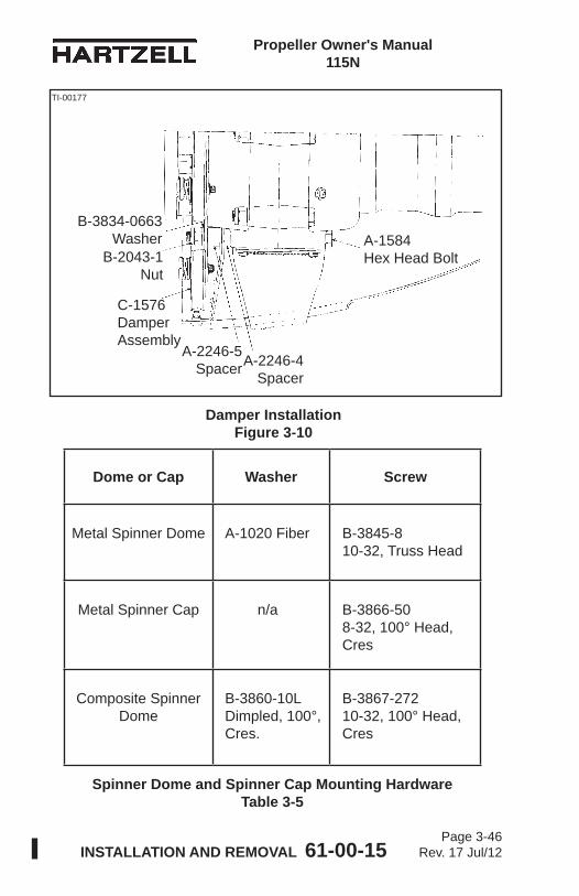
Propeller Owner's Manual 115N
INSTALLATION AND REMOVAL 61-00-15 Page 3-46
Rev. 17 Jul/12
Dome or Cap Washer Screw
Metal Spinner Dome A-1020 Fiber B-3845-8 10-32, Truss Head
Metal Spinner Cap n/a B-3866-50 8-32, 100° Head, Cres
Composite Spinner Dome
B-3860-10L Dimpled, 100°, Cres.
B-3867-272 10-32, 100° Head, Cres
Spinner Dome and Spinner Cap Mounting Hardware Table 3-5
Damper Installation Figure 3-10
B-3834-0663 Washer
B-2043-1 Nut
C-1576 Damper Assembly
A-2246-5 SpacerA-2246-4
Spacer
A-1584 Hex Head Bolt
TI-00177
Propeller Owner's Manual 115N
INSTALLATION AND REMOVAL 61-00-15 Page 3-47
Rev. 17 Jul/12
5. Damper Installation A. Installation of C-1576 Damper (Hartzell Propeller Inc. Kit
A-1583)
CAUTION: USE WITH A-2476-16 SPINNER MOUNTING KIT ONLY.
(1) Use the A-2476-16 spinner mounting kit when installing the C-1576 damper assembly (Figure 3-10).(a) Remove four of the B-3834-0663 washers from the
A-2476-16 spinner mounting kit when installing the C-1576 damper assembly.
(2) Install the propeller spinner dome and cap in accordance with the section “Spinner Installation” in this chapter.
6. Spinner Installation
CAUTION: TO PREVENT DAMAGE TO THE BLADE AND BLADE PAINT, WRAP THE BLADE SHANKS IN SEVERAL LAYERS OF MASKING OR DUCT TAPE BEFORE INSTALLING THE SPINNER DOME. REMOVE THE TAPE AFTER THE SPINNER IS INSTALLED.
A. Single Piece Spinner Dome(1) The following instructions relate to Hartzell Propeller Inc.
spinners only. In some cases, the airframe manufacturer produced the spinner assembly. If so, refer to the airframe manufacturer’s manual for spinner installation instructions.
(2) Examine the interior of the spinner dome. If the spinner dome has an internal support (see Figure 2-3) that encircles the propeller cylinder, the cylinder may need to be wrapped with one or more layers of UHMW tape (Hartzell Propeller Inc. P/N B-6654-100).
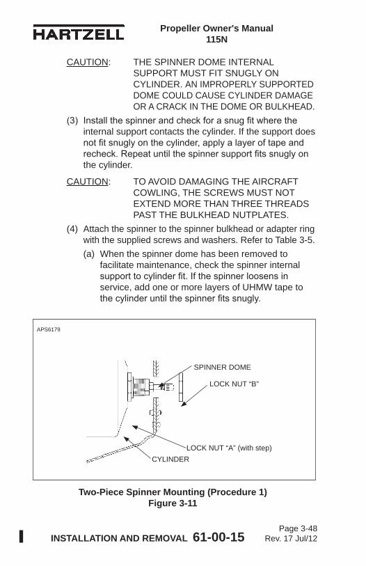
Propeller Owner's Manual 115N
INSTALLATION AND REMOVAL 61-00-15 Page 3-48
Rev. 17 Jul/12
Two-Piece Spinner Mounting (Procedure 1) Figure 3-11
APS6179
SPINNER DOME
LOCK NUT “B”
CYLINDERLOCK NUT “A” (with step)
CAUTION: THE SPINNER DOME INTERNAL SUPPORT MUST FIT SNUGLY ON CYLINDER. AN IMPROPERLY SUPPORTED DOME COULD CAUSE CYLINDER DAMAGE OR A CRACK IN THE DOME OR BULKHEAD.
(3) Install the spinner and check for a snug fit where the internal support contacts the cylinder. If the support does not fit snugly on the cylinder, apply a layer of tape and recheck. Repeat until the spinner support fits snugly on the cylinder.
CAUTION: TO AVOID DAMAGING THE AIRCRAFT COWLING, THE SCREWS MUST NOT EXTEND MORE THAN THREE THREADS PAST THE BULKHEAD NUTPLATES.
(4) Attach the spinner to the spinner bulkhead or adapter ring with the supplied screws and washers. Refer to Table 3-5.(a) When the spinner dome has been removed to
facilitate maintenance, check the spinner internal support to cylinder fit. If the spinner loosens in service, add one or more layers of UHMW tape to the cylinder until the spinner fits snugly.
Propeller Owner's Manual 115N
INSTALLATION AND REMOVAL 61-00-15 Page 3-49
Rev. 17 Jul/12
B. Two-Piece Spinner Dome (Procedure 1)(1) General
(a) A spinner dome that is installed using Procedure 1 may be identified by the lock nut “A” at the top of the cylinder. The lock nut “A” will have a “step” facing away from the cylinder as illustrated in Figure 3-11.1 Lock nut “A” may have drilled holes for safety
wire, but safety wire is not required in this location.
(b) The following instructions relate to Hartzell Propeller Inc. spinners only. In some cases, the airframe manufacturer produced the spinner assembly. If so, refer to the airframe manufacturer’s manual for spinner installation instructions.
(2) Procedure - Refer to Figure 3-11. (a) Install the spinner dome. (b) Push the spinner dome toward the bulkhead to
align the spinner mounting holes with those of the bulkhead.
(c) Using screws and washers, attach the spinner to the bulkhead or adapter ring. Refer to Table 3-5.
(d) Install the lock nut “B” on the low pitch stop. Refer to Table 3-1 and Figure 3-1 for lock nut torque.
(e) Safety wire the lock nut “B” to each of the two screws on the flat face of the spinner dome surrounding the lock nut “B”.
CAUTION: MAKE SURE THAT THE SCREWS DO NOT EXTEND MORE THAN THREE THREADS PAST THE BULKHEAD NUTPLATES. IF THE SCREWS EXTEND MORE THAN THREE THREADS, THIS CAN CAUSE DAMAGE TO THE AIRCRAFT COWLING.
(f) Using flat head screws, attach the spinner dome cap to the spinner dome. Refer to Table 3-5.
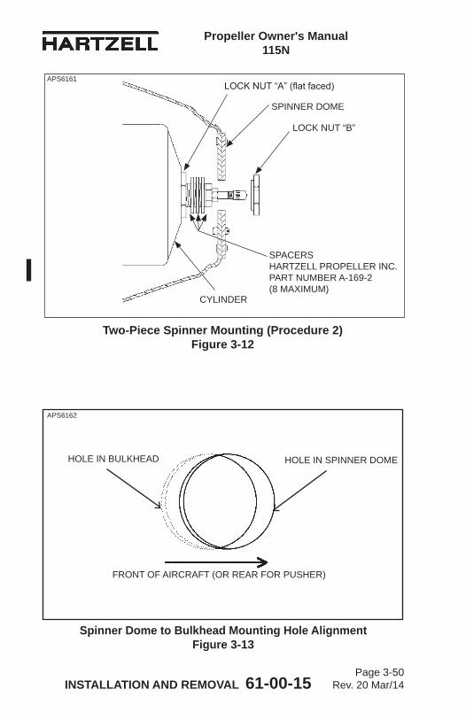
Propeller Owner's Manual 115N
INSTALLATION AND REMOVAL 61-00-15 Page 3-50
Rev. 20 Mar/14
SPINNER DOME
CYLINDER
LOCK NUT “B”
SPACERSHARTZELL PROPELLER INC. PART NUMBER A-169-2 (8 MAXIMUM)
APS6161
Two-Piece Spinner Mounting (Procedure 2) Figure 3-12
HOLE IN BULKHEAD HOLE IN SPINNER DOME
FRONT OF AIRCRAFT (OR REAR FOR PUSHER)
Spinner Dome to Bulkhead Mounting Hole Alignment Figure 3-13
APS6162
LOCK NUT “A” (flat faced)
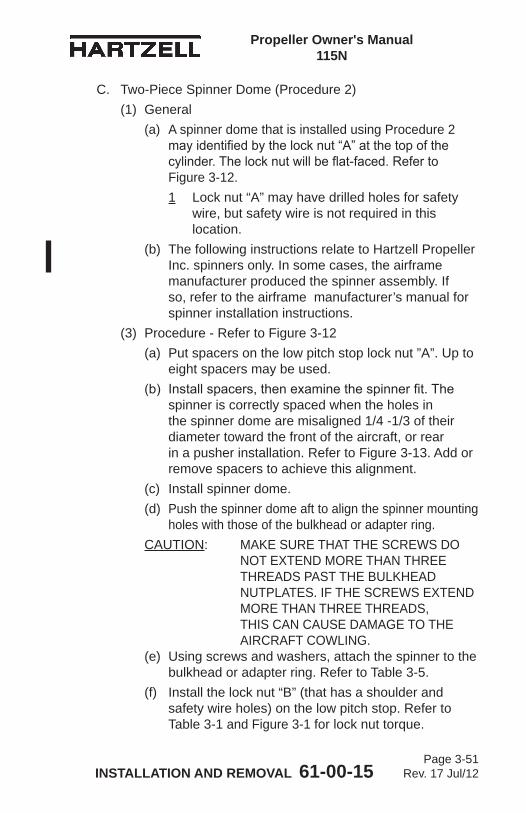
Propeller Owner's Manual 115N
INSTALLATION AND REMOVAL 61-00-15 Page 3-51
Rev. 17 Jul/12
C. Two-Piece Spinner Dome (Procedure 2)(1) General
(a) A spinner dome that is installed using Procedure 2 may identified by the lock nut “A” at the top of the cylinder. The lock nut will be flat-faced. Refer to Figure 3-12.1 Lock nut “A” may have drilled holes for safety
wire, but safety wire is not required in this location.
(b) The following instructions relate to Hartzell Propeller Inc. spinners only. In some cases, the airframe manufacturer produced the spinner assembly. If so, refer to the airframe manufacturer’s manual for spinner installation instructions.
(3) Procedure - Refer to Figure 3-12 (a) Put spacers on the low pitch stop lock nut ”A”. Up to
eight spacers may be used. (b) Install spacers, then examine the spinner fit. The
spinner is correctly spaced when the holes in the spinner dome are misaligned 1/4 -1/3 of their diameter toward the front of the aircraft, or rear in a pusher installation. Refer to Figure 3-13. Add or remove spacers to achieve this alignment.
(c) Install spinner dome. (d) Push the spinner dome aft to align the spinner mounting
holes with those of the bulkhead or adapter ring. CAUTION: MAKE SURE THAT THE SCREWS DO
NOT EXTEND MORE THAN THREE THREADS PAST THE BULKHEAD NUTPLATES. IF THE SCREWS EXTEND MORE THAN THREE THREADS, THIS CAN CAUSE DAMAGE TO THE AIRCRAFT COWLING.
(e) Using screws and washers, attach the spinner to the bulkhead or adapter ring. Refer to Table 3-5.
(f) Install the lock nut “B” (that has a shoulder and safety wire holes) on the low pitch stop. Refer to Table 3-1 and Figure 3-1 for lock nut torque.
Propeller Owner's Manual 115N
INSTALLATION AND REMOVAL 61-00-15 Page 3-52
Rev. 17 Jul/12
(g) Safety wire the lock nut to each of the two screws on the flat face of the spinner dome surrounding the lock nut.
(h) Using flat head screws, attach the spinner dome cap to the spinner dome.
7. Post-Installation ChecksPerform Static RPM Check as outlined in the Testing and Troubleshooting chapter in this manual.
8. Spinner Removal
CAUTION: WRAP THE BLADE SHANKS IN SEVERAL LAYERS OF MASKING OR DUCT TAPE BEFORE REMOVING THE SPINNER DOME TO PREVENT DAMAGING THE BLADE AND BLADE PAINT.
A. Removal of Single Piece Spinner(1) Remove the screws and washers that attach the spinner
to the spinner bulkhead or adapter ring.(2) Remove the spinner dome.
B. Removal of Two-Piece Spinner(1) Remove the flat head screws that attach the spinner
dome cap to the spinner dome.(2) Cut and remove the lock nut safety wire.(3) Remove the lock nut.(4) Remove the screws and washers that attach the spinner
dome to the spinner bulkhead.(5) Remove the spinner dome.
C. Hub Mounted Spinner Bulkhead Removal(1) Remove propeller. Refer to Propeller Removal in this
chapter.(2) Remove the flat washers and self-locking nuts that
attach the spinner bulkhead to the propeller hub. Remove the spinner bulkhead.
(3) Reinstall the flat washers and self-locking nuts that were removed during the spinner bulkhead removal.
Propeller Owner's Manual 115N
INSTALLATION AND REMOVAL 61-00-15 Page 3-53
Rev. 17 Jul/12
D. Starter Ring Gear Spinner Adapter Removal(1) Remove propeller. Refer to Propeller Removal in this
chapter.(2) Remove the spinner adapter by removing the hardware
that attaches the spinner adapter to the starter ring gear.
9. Propeller RemovalA. Removal of “D” Flange Propellers
(1) Remove the spinner dome in accordance with the Spinner Removal procedures in this chapter.
(2) If the propeller is equipped with an ice protection system that uses components supplied by Hartzell Propeller Inc., applicable instructions and technical information for the components supplied by Hartzell Propeller Inc. can be found in the following publications available on the Hartzell Propeller Inc. website at www.hartzellprop.com:(a) Manual 180 (30-61-80) - Propeller Ice Protection
System Manual (b) Manual 181 (30-60-81) - Propeller Ice Protection
System Component Maintenance Manual(c) Manual 182 (61-12-82) - Propeller Electrical De-Ice
Boot Removal and Installation Manual(d) Manual 183 (61-12-83) - Propeller Anti-Icing Boot
Removal and Installation Manual(3) Propeller ice protection system components not
supplied by Hartzell Propeller Inc. are controlled by the applicable TC or STC holder’s Instructions for Continued Airworthiness (ICA).
(4) Cut and remove the safety wire (if installed) on the propeller mounting studs.
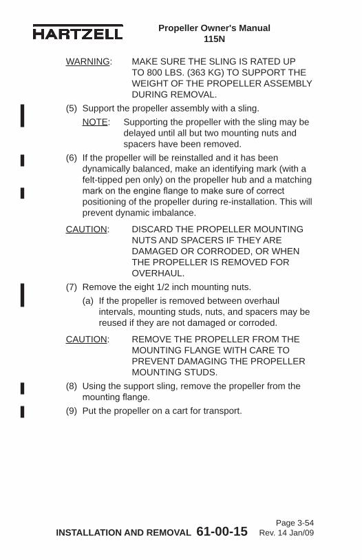
Propeller Owner's Manual 115N
INSTALLATION AND REMOVAL 61-00-15 Page 3-54
Rev. 14 Jan/09
WARNING: MAKE SURE THE SLING IS RATED UP TO 800 LBS. (363 KG) TO SUPPORT THE WEIGHT OF THE PROPELLER ASSEMBLY DURING REMOVAL.
(5) Support the propeller assembly with a sling.NOTE: Supporting the propeller with the sling may be
delayed until all but two mounting nuts and spacers have been removed.
(6) If the propeller will be reinstalled and it has been dynamically balanced, make an identifying mark (with a felt-tipped pen only) on the propeller hub and a matching mark on the engine flange to make sure of correct positioning of the propeller during re-installation. This will prevent dynamic imbalance.
CAUTION: DISCARD THE PROPELLER MOUNTING NUTS AND SPACERS IF THEY ARE DAMAGED OR CORRODED, OR WHEN THE PROPELLER IS REMOVED FOR OVERHAUL.
(7) Remove the eight 1/2 inch mounting nuts.(a) If the propeller is removed between overhaul
intervals, mounting studs, nuts, and spacers may be reused if they are not damaged or corroded.
CAUTION: REMOVE THE PROPELLER FROM THE MOUNTING FLANGE WITH CARE TO PREVENT DAMAGING THE PROPELLER MOUNTING STUDS.
(8) Using the support sling, remove the propeller from the mounting flange.
(9) Put the propeller on a cart for transport.
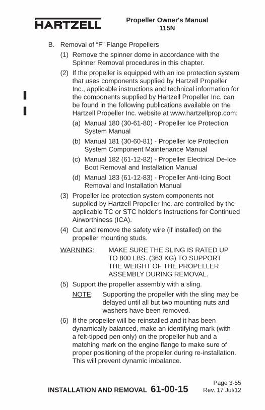
Propeller Owner's Manual 115N
INSTALLATION AND REMOVAL 61-00-15 Page 3-55
Rev. 17 Jul/12
B. Removal of “F” Flange Propellers(1) Remove the spinner dome in accordance with the
Spinner Removal procedures in this chapter.(2) If the propeller is equipped with an ice protection system
that uses components supplied by Hartzell Propeller Inc., applicable instructions and technical information for the components supplied by Hartzell Propeller Inc. can be found in the following publications available on the Hartzell Propeller Inc. website at www.hartzellprop.com:(a) Manual 180 (30-61-80) - Propeller Ice Protection
System Manual (b) Manual 181 (30-60-81) - Propeller Ice Protection
System Component Maintenance Manual(c) Manual 182 (61-12-82) - Propeller Electrical De-Ice
Boot Removal and Installation Manual(d) Manual 183 (61-12-83) - Propeller Anti-Icing Boot
Removal and Installation Manual(3) Propeller ice protection system components not
supplied by Hartzell Propeller Inc. are controlled by the applicable TC or STC holder’s Instructions for Continued Airworthiness (ICA).
(4) Cut and remove the safety wire (if installed) on the propeller mounting studs.
WARNING: MAKE SURE THE SLING IS RATED UP TO 800 LBS. (363 KG) TO SUPPORT THE WEIGHT OF THE PROPELLER ASSEMBLY DURING REMOVAL.
(5) Support the propeller assembly with a sling.NOTE: Supporting the propeller with the sling may be
delayed until all but two mounting nuts and washers have been removed.
(6) If the propeller will be reinstalled and it has been dynamically balanced, make an identifying mark (with a felt-tipped pen only) on the propeller hub and a matching mark on the engine flange to make sure of proper positioning of the propeller during re-installation. This will prevent dynamic imbalance.
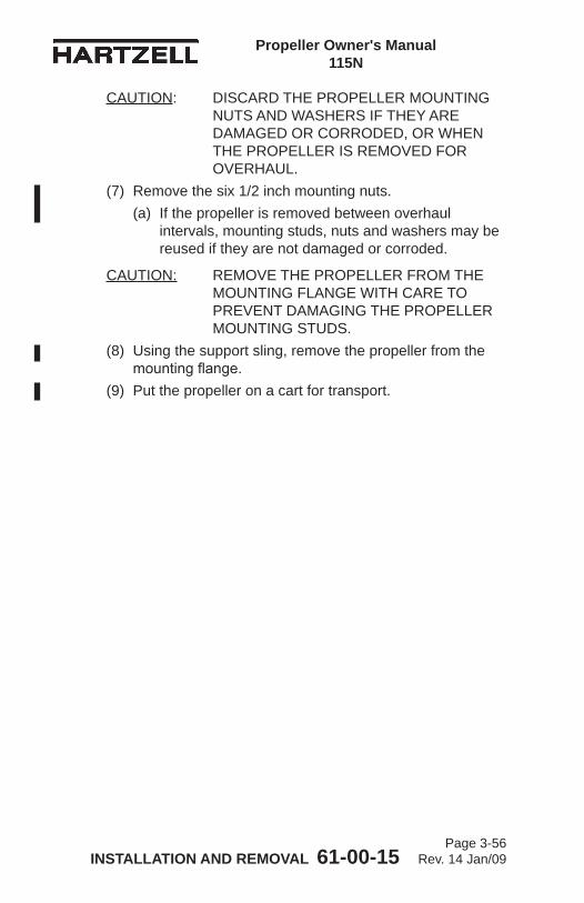
Propeller Owner's Manual 115N
INSTALLATION AND REMOVAL 61-00-15 Page 3-56
Rev. 14 Jan/09
CAUTION: DISCARD THE PROPELLER MOUNTING NUTS AND WASHERS IF THEY ARE DAMAGED OR CORRODED, OR WHEN THE PROPELLER IS REMOVED FOR OVERHAUL.
(7) Remove the six 1/2 inch mounting nuts.(a) If the propeller is removed between overhaul
intervals, mounting studs, nuts and washers may be reused if they are not damaged or corroded.
CAUTION: REMOVE THE PROPELLER FROM THE MOUNTING FLANGE WITH CARE TO PREVENT DAMAGING THE PROPELLER MOUNTING STUDS.
(8) Using the support sling, remove the propeller from the mounting flange.
(9) Put the propeller on a cart for transport.
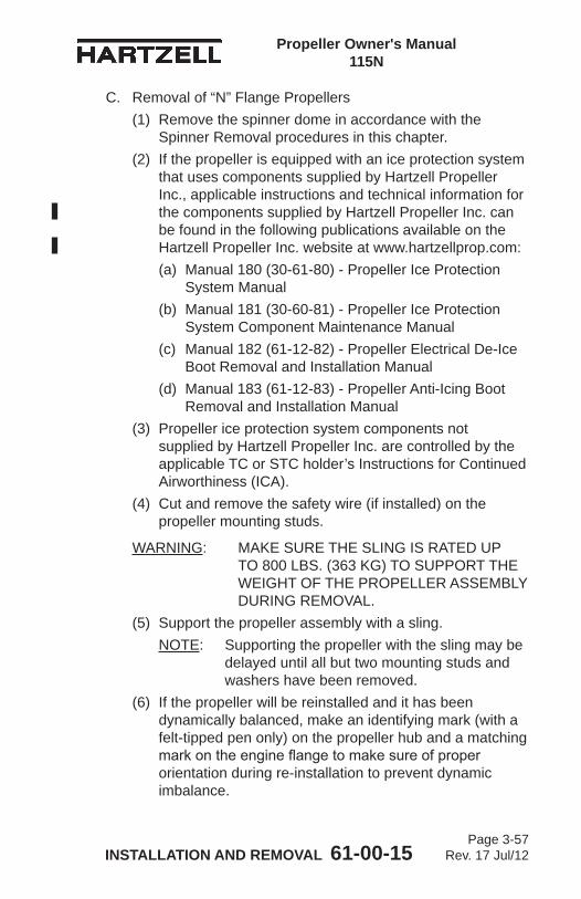
Propeller Owner's Manual 115N
INSTALLATION AND REMOVAL 61-00-15 Page 3-57
Rev. 17 Jul/12
C. Removal of “N” Flange Propellers(1) Remove the spinner dome in accordance with the
Spinner Removal procedures in this chapter.(2) If the propeller is equipped with an ice protection system
that uses components supplied by Hartzell Propeller Inc., applicable instructions and technical information for the components supplied by Hartzell Propeller Inc. can be found in the following publications available on the Hartzell Propeller Inc. website at www.hartzellprop.com:(a) Manual 180 (30-61-80) - Propeller Ice Protection
System Manual (b) Manual 181 (30-60-81) - Propeller Ice Protection
System Component Maintenance Manual(c) Manual 182 (61-12-82) - Propeller Electrical De-Ice
Boot Removal and Installation Manual(d) Manual 183 (61-12-83) - Propeller Anti-Icing Boot
Removal and Installation Manual(3) Propeller ice protection system components not
supplied by Hartzell Propeller Inc. are controlled by the applicable TC or STC holder’s Instructions for Continued Airworthiness (ICA).
(4) Cut and remove the safety wire (if installed) on the propeller mounting studs.
WARNING: MAKE SURE THE SLING IS RATED UP TO 800 LBS. (363 KG) TO SUPPORT THE WEIGHT OF THE PROPELLER ASSEMBLY DURING REMOVAL.
(5) Support the propeller assembly with a sling.NOTE: Supporting the propeller with the sling may be
delayed until all but two mounting studs and washers have been removed.
(6) If the propeller will be reinstalled and it has been dynamically balanced, make an identifying mark (with a felt-tipped pen only) on the propeller hub and a matching mark on the engine flange to make sure of proper orientation during re-installation to prevent dynamic imbalance.
Propeller Owner's Manual 115N
INSTALLATION AND REMOVAL 61-00-15 Page 3-58
Rev. 14 Jan/09
CAUTION: DISCARD THE PROPELLER MOUNTING NUTS AND WASHERS IF THEY ARE DAMAGED OR CORRODED, OR WHEN THE PROPELLER IS REMOVED FOR OVERHAUL.
(7) Remove the eight 9/16 inch mounting nuts.(a) If the propeller is removed between overhaul
intervals, mounting studs, nuts and washers may be reused if they are not damaged or corroded.
CAUTION: REMOVE THE PROPELLER FROM THE ENGINE MOUNTING FLANGE WITH CARE TO PREVENT DAMAGING THE PROPELLER MOUNTING STUDS.
(8) Using the support sling, remove the propeller from the mounting flange.
(9) Put the propeller on a cart for transport.
Propeller Owner's Manual 115N
INSTALLATION AND REMOVAL 61-00-15 Page 3-59
Rev. 17 Jul/12
D. Removal of “L” Flange Propellers (except model HC-E2YL-[ ]) (1) Remove the spinner dome in accordance with the
Spinner Removal procedures in this chapter.(2) If the propeller is equipped with an ice protection system
that uses components supplied by Hartzell Propeller Inc., applicable instructions and technical information for the components supplied by Hartzell Propeller Inc. can be found in the following publications available on the Hartzell Propeller Inc. website at www.hartzellprop.com:(a) Manual 180 (30-61-80) - Propeller Ice Protection
System Manual (b) Manual 181 (30-60-81) - Propeller Ice Protection
System Component Maintenance Manual(c) Manual 182 (61-12-82) - Propeller Electrical De-Ice
Boot Removal and Installation Manual(d) Manual 183 (61-12-83) - Propeller Anti-Icing Boot
Removal and Installation Manual(3) Propeller ice protection system components not
supplied by Hartzell Propeller Inc. are controlled by the applicable TC or STC holder’s Instructions for Continued Airworthiness (ICA).
(4) Cut and remove the safety wire (if installed) on the propeller mounting stud nuts.
WARNING: MAKE SURE THE SLING IS RATED UP TO 800 LBS. (363 KG) TO SUPPORT THE WEIGHT OF THE PROPELLER ASSEMBLY DURING REMOVAL.
(5) Support the propeller assembly with a sling.(6) If the propeller will be reinstalled and it has been
dynamically balanced, make an identifying mark (with a felt-tipped pen only) on the propeller hub and a matching mark on the engine flange to make sure of proper orientation during re-installation to prevent dynamic imbalance.
Propeller Owner's Manual 115N
INSTALLATION AND REMOVAL 61-00-15 Page 3-60
Rev. 14 Jan/09
CAUTION: DISCARD THE PROPELLER MOUNTING STUDS, NUTS, AND WASHERS IF THEY ARE DAMAGED OR CORRODED, OR WHEN THE PROPELLER IS REMOVED FOR OVERHAUL.
(7) Unscrew the six 7/16 inch mounting studs from the engine bushings.(a) If the propeller is removed between overhaul
intervals, mounting studs, nuts and washers may be reused if they are not damaged or corroded.
CAUTION: REMOVE THE PROPELLER FROM THE ENGINE MOUNTING FLANGE WITH CARE TO PREVENT DAMAGING THE PROPELLER MOUNTING STUDS.
(8) Using the support sling, remove the propeller from the mounting flange.
(9) Put the propeller on a cart for transport.
Propeller Owner's Manual 115N
INSTALLATION AND REMOVAL 61-00-15 Page 3-61
Rev. 17 Jul/12
E. Removal of HC-E2YL-( ) Propellers(1) Remove the spinner dome in accordance with the
Spinner Removal procedures in this chapter.(2) If the propeller is equipped with an ice protection system
that uses components supplied by Hartzell Propeller Inc., applicable instructions and technical information for the components supplied by Hartzell Propeller Inc. can be found in the following publications available on the Hartzell Propeller Inc. website at www.hartzellprop.com:(a) Manual 180 (30-61-80) - Propeller Ice Protection
System Manual (b) Manual 181 (30-60-81) - Propeller Ice Protection
System Component Maintenance Manual(c) Manual 182 (61-12-82) - Propeller Electrical De-Ice
Boot Removal and Installation Manual(d) Manual 183 (61-12-83) - Propeller Anti-Icing Boot
Removal and Installation Manual(3) Propeller ice protection system components not
supplied by Hartzell Propeller Inc. are controlled by the applicable TC or STC holder’s Instructions for Continued Airworthiness (ICA).
(4) Cut and remove the safety wire (if installed) on the propeller mounting stud nuts.
WARNING: MAKE SURE THE SLING IS RATED UP TO 800 LBS. (363 KG) TO SUPPORT THE WEIGHT OF THE PROPELLER ASSEMBLY DURING REMOVAL.
(5) Support the propeller assembly with a sling.(6) If the propeller will be reinstalled and it has been
dynamically balanced, make an identifying mark (with a felt-tipped pen only) on the propeller hub and a matching mark on the engine flange to make sure of proper orientation during re-installation to prevent dynamic imbalance.
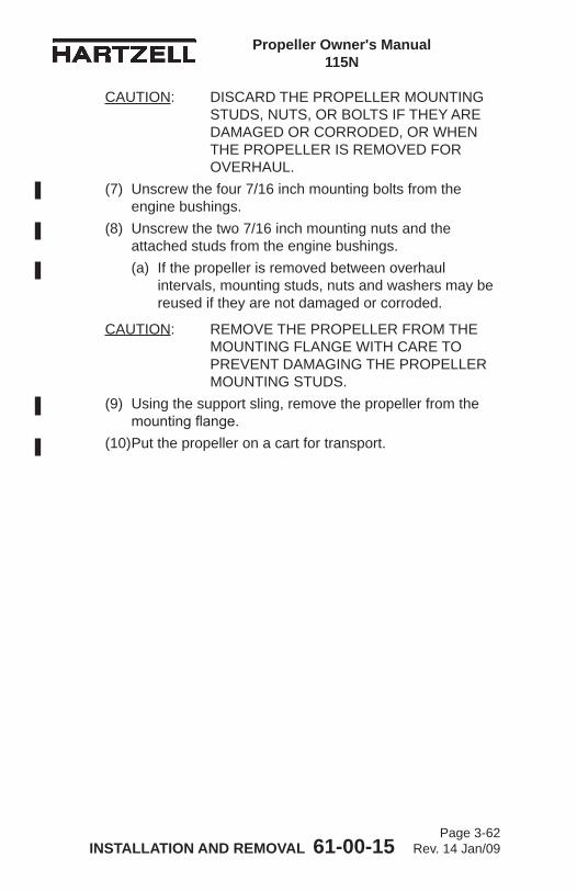
Propeller Owner's Manual 115N
INSTALLATION AND REMOVAL 61-00-15 Page 3-62
Rev. 14 Jan/09
CAUTION: DISCARD THE PROPELLER MOUNTING STUDS, NUTS, OR BOLTS IF THEY ARE DAMAGED OR CORRODED, OR WHEN THE PROPELLER IS REMOVED FOR OVERHAUL.
(7) Unscrew the four 7/16 inch mounting bolts from the engine bushings.
(8) Unscrew the two 7/16 inch mounting nuts and the attached studs from the engine bushings.(a) If the propeller is removed between overhaul
intervals, mounting studs, nuts and washers may be reused if they are not damaged or corroded.
CAUTION: REMOVE THE PROPELLER FROM THE MOUNTING FLANGE WITH CARE TO PREVENT DAMAGING THE PROPELLER MOUNTING STUDS.
(9) Using the support sling, remove the propeller from the mounting flange.
(10) Put the propeller on a cart for transport.
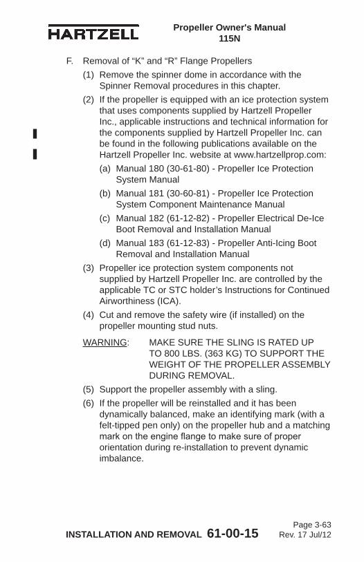
Propeller Owner's Manual 115N
INSTALLATION AND REMOVAL 61-00-15 Page 3-63
Rev. 17 Jul/12
F. Removal of “K” and “R” Flange Propellers(1) Remove the spinner dome in accordance with the
Spinner Removal procedures in this chapter.(2) If the propeller is equipped with an ice protection system
that uses components supplied by Hartzell Propeller Inc., applicable instructions and technical information for the components supplied by Hartzell Propeller Inc. can be found in the following publications available on the Hartzell Propeller Inc. website at www.hartzellprop.com:(a) Manual 180 (30-61-80) - Propeller Ice Protection
System Manual (b) Manual 181 (30-60-81) - Propeller Ice Protection
System Component Maintenance Manual(c) Manual 182 (61-12-82) - Propeller Electrical De-Ice
Boot Removal and Installation Manual(d) Manual 183 (61-12-83) - Propeller Anti-Icing Boot
Removal and Installation Manual(3) Propeller ice protection system components not
supplied by Hartzell Propeller Inc. are controlled by the applicable TC or STC holder’s Instructions for Continued Airworthiness (ICA).
(4) Cut and remove the safety wire (if installed) on the propeller mounting stud nuts.
WARNING: MAKE SURE THE SLING IS RATED UP TO 800 LBS. (363 KG) TO SUPPORT THE WEIGHT OF THE PROPELLER ASSEMBLY DURING REMOVAL.
(5) Support the propeller assembly with a sling.(6) If the propeller will be reinstalled and it has been
dynamically balanced, make an identifying mark (with a felt-tipped pen only) on the propeller hub and a matching mark on the engine flange to make sure of proper orientation during re-installation to prevent dynamic imbalance.
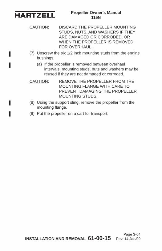
Propeller Owner's Manual 115N
INSTALLATION AND REMOVAL 61-00-15 Page 3-64
Rev. 14 Jan/09
CAUTION: DISCARD THE PROPELLER MOUNTING STUDS, NUTS, AND WASHERS IF THEY ARE DAMAGED OR CORRODED, OR WHEN THE PROPELLER IS REMOVED FOR OVERHAUL.
(7) Unscrew the six 1/2 inch mounting studs from the engine bushings.(a) If the propeller is removed between overhaul
intervals, mounting studs, nuts and washers may be reused if they are not damaged or corroded.
CAUTION: REMOVE THE PROPELLER FROM THE MOUNTING FLANGE WITH CARE TO PREVENT DAMAGING THE PROPELLER MOUNTING STUDS.
(8) Using the support sling, remove the propeller from the mounting flange.
(9) Put the propeller on a cart for transport.
Propeller Owner's Manual 115N
TESTING AND TROUBLESHOOTING 61-00-15 Page 4-1
Rev. 20 Mar/14
TESTING AND TROUBLESHOOTING - CONTENTS
1. Operational Tests .......................................................................4-3A. General ..............................................................................4-3B. Initial Run-Up .....................................................................4-3C. Static RPM Check .............................................................4-4D. Post-Run Check ................................................................4-4
2. Propeller Ice Protection Systems ...............................................4-5A. Electric De-ice System ......................................................4-5B. Anti-ice System ..................................................................4-5
3. Troubleshooting ..........................................................................4-6A. Hunting and Surging ..........................................................4-6B. Engine Speed Varies with Flight Attitude (Airspeed) .........4-6C. Loss of Propeller Control (-1 propellers only) ....................4-8D. Loss of Propeller Control (-2, -4 or -5 propellers) ..............4-8E. Failure to Feather or Feathers Slowly
(-2 or -5 propellers only) ....................................................4-9F. Failure to Unfeather ...........................................................4-9G. Start Locks (Anti-feather Latches) Fail to Latch on
Shutdown (-2 and some -5 feathering propellers only) ....4-10H. Vibration ..........................................................................4-11I. Propeller Overspeed ........................................................4-12J. Propeller Underspeed ......................................................4-13K. Oil or Grease Leakage ....................................................4-13

Propeller Owner's Manual 115N
TESTING AND TROUBLESHOOTING 61-00-15 Page 4-2
Rev. 20 Mar/14
(This page is intentionally blank.)
Propeller Owner's Manual 115N
TESTING AND TROUBLESHOOTING 61-00-15 Page 4-3
Rev. 20 Mar/14
1. Operational Tests
CAUTION: INSTRUCTIONS AND PROCEDURES IN THIS SECTION MAY INVOLVE PROPELLER CRITICAL PARTS. REFER TO THE INTRODUCTION CHAPTER OF THIS MANUAL FOR INFORMATION ABOUT PROPELLER CRITICAL PARTS. REFER TO THE ILLUSTRATED PARTS LIST CHAPTER OF THE APPLICABLE OVERHAUL MANUAL(S) FOR THE IDENTIFICATION OF SPECIFIC PROPELLER CRITICAL PARTS.
A. General(1) The propeller must be installed on an application using
a propeller governor.(2) Perform the test after propeller installation and before
every flight.(3) The propeller system must be purged of air and correct
operation verified.B. Initial Run-Up
(1) Perform engine start and warm-up per the Pilot's Operating Handbook (POH).
CAUTION: AIR TRAPPED IN THE PROPELLER HYDRAULIC SYSTEM WILL CAUSE THE PITCH CONTROL TO BE IMPRECISE AND MAY RESULT IN PROPELLER SURGING.
(2) Cycle the propeller control throughout its operating range from low to high (or as directed by the POH).
(3) Repeat this procedure at least three times to purge air from the propeller hydraulic system and to introduce warmed oil to the cylinder.NOTE: Pitch change response on the first operation
from low to high blade pitch may be slow, but should speed up on the second and third cycles.
(4) Verify proper operation from low pitch to high pitch and throughout operating range.
(5) Shut down the engine in accordance with the POH.
Propeller Owner's Manual 115N
TESTING AND TROUBLESHOOTING 61-00-15 Page 4-4
Rev. 20 Mar/14
C. Static RPM CheckNOTE: This operational check should be performed after
installation, maintenance, or propeller adjustment.CAUTION: A CALIBRATED TACHOMETER MUST
BE USED TO MAKE SURE OF THE ACCURACY OF THE RPM CHECK.
(1) Set the brakes and chock the aircraft or tie aircraft down. (2) Back the governor Maximum RPM Stop out one turn.(3) Start the engine.(4) Advance the propeller control lever to MAX (max RPM),
then retard the control lever one inch (25.4 mm).(5) SLOWLY advance the throttle to maximum manifold
pressure.(6) Slowly advance the propeller control lever until the engine
speed stabilizes.(a) If engine speed stabilizes at the maximum power
static RPM specified by the TC or STC holder, then the low pitch stop is set correctly.
(b) If engine speed stabilizes above or below the rated RPM, the low pitch stop may require adjustment. Refer to the Maintenance Practices chapter of this manual.
(7) Stop the engine.(8) Return the governor Maximum RPM Stop to the original
position, or adjust the governor to the rated RPM with the Maximum RPM Stop screw.(a) If the governor is adjusted to the rated RPM with the
maximum RPM stop screw, hold the maximum RPM stop screw in place and torque the maximum RPM stop locking nut in accordance with Table 3-1, Torque Table.
CAUTION: REFER TO THE AIRCRAFT MAINTENANCE MANUAL FOR ADDITIONAL PROCEDURES THAT MAY BE REQUIRED AFTER PROPELLER INSTALLATION.
D. Post-Run Check(1) After engine shutdown, check propeller for signs of
engine oil leakage.
Propeller Owner's Manual 115N
TESTING AND TROUBLESHOOTING 61-00-15 Page 4-5
Rev. 14 Jan/09
2. Propeller Ice Protection SystemsA. Electric De-ice System
(1) Consult the Pilot Operating Handbook (including all supplements) regarding flight into conditions of known icing. The aircraft may not be certificated for flight in known icing conditions, even though propeller de-ice equipment is installed.
(2) Refer to the Anti-ice and De-ice Systems chapter of this manual for functional tests of the de-ice system.
B. Anti-ice System(1) Consult the Pilot Operating Handbook (including all
supplements) regarding flight into conditions of known icing. The aircraft may not be certificated for flight in known icing conditions, even though propeller anti-ice equipment is installed.
(2) Refer to the Anti-ice and De-ice Systems Chapter of this manual for functional tests of the anti-ice system.
Propeller Owner's Manual 115N
TESTING AND TROUBLESHOOTING 61-00-15 Page 4-6
Rev. 17 Jul/12
3. Troubleshooting
CAUTION: INSTRUCTIONS AND PROCEDURES IN THIS SECTION MAY INVOLVE PROPELLER CRITICAL PARTS. REFER TO THE INTRODUCTION CHAPTER OF THIS MANUAL FOR INFORMATION ABOUT PROPELLER CRITICAL PARTS. REFER TO THE ILLUSTRATED PARTS LIST CHAPTER OF THE APPLICABLE OVERHAUL MANUAL(S) FOR THE IDENTIFICATION OF SPECIFIC PROPELLER CRITICAL PARTS.
A. Hunting and SurgingHunting is characterized by a cyclic variation in engine speed above and below desired speed. Surging is characterized by a large increase/decrease in engine speed, followed by a return to set speed after one or two occurrences. (1) If propeller is hunting, an appropriately licensed repair
facility should check:(a) Governor(b) Fuel control(c) Synchrophaser or synchronizer
(2) If propeller is surging:Perform Steps 1.A.(1)-1.A.(5) under "Operational Tests," in this chapter to release trapped air from the propeller. If surging recurs, it is most likely due to a faulty governor. Have the governor tested by an appropriately licensed propeller repair facility.
(3) Hunting and/or surging may also be caused by friction or binding within the governor control, or by internal propeller corrosion, which causes the propeller to react slower to governor commands. The propeller must be tested at an appropriately licensed propeller repair facility to isolate these faults.
B. Engine Speed Varies with Flight Attitude (Airspeed)(1) Small variances in engine speed are normal and are no
cause for concern.
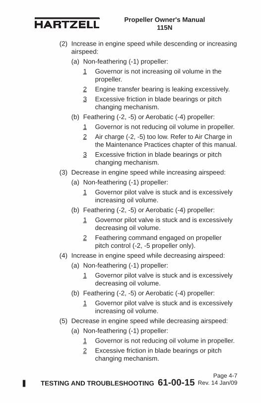
Propeller Owner's Manual 115N
TESTING AND TROUBLESHOOTING 61-00-15 Page 4-7
Rev. 14 Jan/09
(2) Increase in engine speed while descending or increasing airspeed:(a) Non-feathering (-1) propeller:
1 Governor is not increasing oil volume in the propeller.
2 Engine transfer bearing is leaking excessively.3 Excessive friction in blade bearings or pitch
changing mechanism.(b) Feathering (-2, -5) or Aerobatic (-4) propeller:
1 Governor is not reducing oil volume in propeller.2 Air charge (-2, -5) too low. Refer to Air Charge in
the Maintenance Practices chapter of this manual.3 Excessive friction in blade bearings or pitch
changing mechanism.(3) Decrease in engine speed while increasing airspeed:
(a) Non-feathering (-1) propeller:1 Governor pilot valve is stuck and is excessively
increasing oil volume.(b) Feathering (-2, -5) or Aerobatic (-4) propeller:
1 Governor pilot valve is stuck and is excessively decreasing oil volume.
2 Feathering command engaged on propeller pitch control (-2, -5 propeller only).
(4) Increase in engine speed while decreasing airspeed:(a) Non-feathering (-1) propeller:
1 Governor pilot valve is stuck and is excessively decreasing oil volume.
(b) Feathering (-2, -5) or Aerobatic (-4) propeller:1 Governor pilot valve is stuck and is excessively
increasing oil volume.(5) Decrease in engine speed while decreasing airspeed:
(a) Non-feathering (-1) propeller:1 Governor is not reducing oil volume in propeller.2 Excessive friction in blade bearings or pitch
changing mechanism.
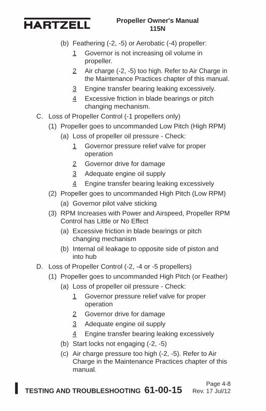
Propeller Owner's Manual 115N
TESTING AND TROUBLESHOOTING 61-00-15 Page 4-8
Rev. 17 Jul/12
(b) Feathering (-2, -5) or Aerobatic (-4) propeller:1 Governor is not increasing oil volume in
propeller.2 Air charge (-2, -5) too high. Refer to Air Charge in
the Maintenance Practices chapter of this manual.3 Engine transfer bearing leaking excessively.4 Excessive friction in blade bearings or pitch
changing mechanism.C. Loss of Propeller Control (-1 propellers only)
(1) Propeller goes to uncommanded Low Pitch (High RPM)(a) Loss of propeller oil pressure - Check:
1 Governor pressure relief valve for proper operation
2 Governor drive for damage3 Adequate engine oil supply4 Engine transfer bearing leaking excessively
(2) Propeller goes to uncommanded High Pitch (Low RPM)(a) Governor pilot valve sticking
(3) RPM Increases with Power and Airspeed, Propeller RPM Control has Little or No Effect(a) Excessive friction in blade bearings or pitch
changing mechanism(b) Internal oil leakage to opposite side of piston and
into hubD. Loss of Propeller Control (-2, -4 or -5 propellers)
(1) Propeller goes to uncommanded High Pitch (or Feather)(a) Loss of propeller oil pressure - Check:
1 Governor pressure relief valve for proper operation
2 Governor drive for damage3 Adequate engine oil supply4 Engine transfer bearing leaking excessively
(b) Start locks not engaging (-2, -5)(c) Air charge pressure too high (-2, -5). Refer to Air
Charge in the Maintenance Practices chapter of this manual.
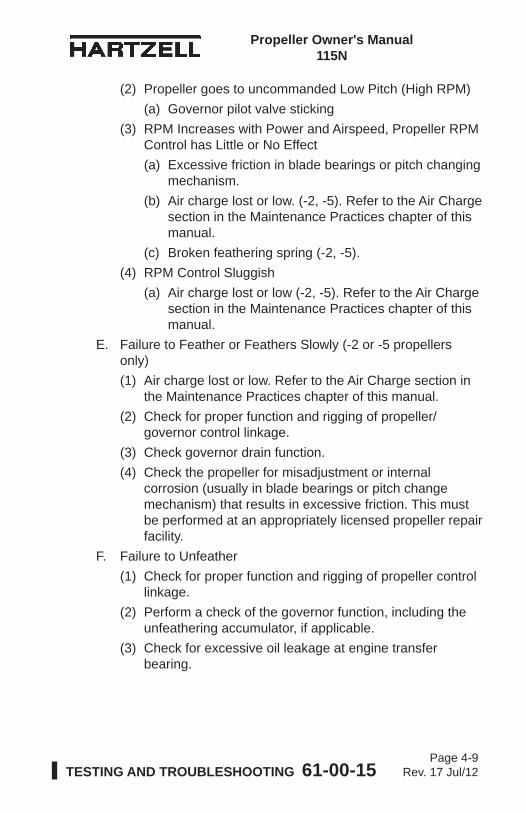
Propeller Owner's Manual 115N
TESTING AND TROUBLESHOOTING 61-00-15 Page 4-9
Rev. 17 Jul/12
(2) Propeller goes to uncommanded Low Pitch (High RPM)(a) Governor pilot valve sticking
(3) RPM Increases with Power and Airspeed, Propeller RPM Control has Little or No Effect(a) Excessive friction in blade bearings or pitch changing
mechanism.(b) Air charge lost or low. (-2, -5). Refer to the Air Charge
section in the Maintenance Practices chapter of this manual.
(c) Broken feathering spring (-2, -5).(4) RPM Control Sluggish
(a) Air charge lost or low (-2, -5). Refer to the Air Charge section in the Maintenance Practices chapter of this manual.
E. Failure to Feather or Feathers Slowly (-2 or -5 propellers only)(1) Air charge lost or low. Refer to the Air Charge section in
the Maintenance Practices chapter of this manual.(2) Check for proper function and rigging of propeller/
governor control linkage.(3) Check governor drain function.(4) Check the propeller for misadjustment or internal
corrosion (usually in blade bearings or pitch change mechanism) that results in excessive friction. This must be performed at an appropriately licensed propeller repair facility.
F. Failure to Unfeather(1) Check for proper function and rigging of propeller control
linkage.(2) Perform a check of the governor function, including the
unfeathering accumulator, if applicable.(3) Check for excessive oil leakage at engine transfer
bearing.
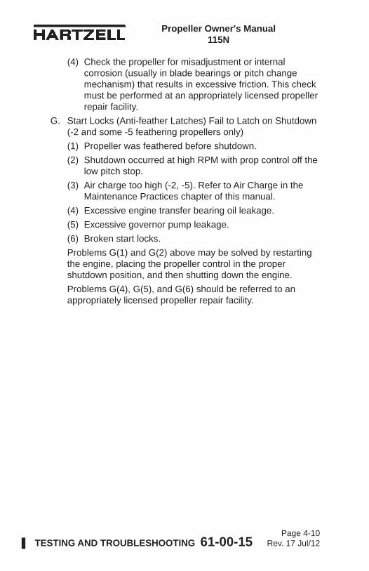
Propeller Owner's Manual 115N
TESTING AND TROUBLESHOOTING 61-00-15 Page 4-10
Rev. 17 Jul/12
(4) Check the propeller for misadjustment or internal corrosion (usually in blade bearings or pitch change mechanism) that results in excessive friction. This check must be performed at an appropriately licensed propeller repair facility.
G. Start Locks (Anti-feather Latches) Fail to Latch on Shutdown (-2 and some -5 feathering propellers only)(1) Propeller was feathered before shutdown.(2) Shutdown occurred at high RPM with prop control off the
low pitch stop.(3) Air charge too high (-2, -5). Refer to Air Charge in the
Maintenance Practices chapter of this manual.(4) Excessive engine transfer bearing oil leakage.(5) Excessive governor pump leakage.(6) Broken start locks.Problems G(1) and G(2) above may be solved by restarting the engine, placing the propeller control in the proper shutdown position, and then shutting down the engine.Problems G(4), G(5), and G(6) should be referred to an appropriately licensed propeller repair facility.
Propeller Owner's Manual 115N
TESTING AND TROUBLESHOOTING 61-00-15 Page 4-11
Rev. 14 Jan/09
H. Vibration
CAUTION 1: ANY VIBRATION THAT OCCURS SUDDENLY, OR IS ACCOMPANIED BY UNEXPLAINED GREASE LEAKAGE SHOULD BE INVESTIGATED IMMEDIATELY BEFORE FURTHER FLIGHT.
CAUTION 2: VIBRATION PROBLEMS BECAUSE OF PROPELLER SYSTEM IMBALANCE ARE NORMALLY FELT THROUGHOUT THE RPM RANGE, WITH THE INTENSITY OF VIBRATION INCREASING WITH RPM. VIBRATION PROBLEMS THAT OCCUR IN A NARROW RPM RANGE ARE A SYMPTOM OF RESONANCE, THAT IS POTENTIALLY HARMFUL TO THE PROPELLER. AVOID OPERATION UNTIL THE PROPELLER CAN BE CHECKED BY AN APPROPRIATELY LICENSED REPAIR FACILITY.
(1) Check:(a) Control surfaces, cowl flaps, exhaust system, landing
gear doors, etc. for excessive play, which may be causing vibration unrelated to the propeller.
(b) Secure attachment of engine mounted hardware.(c) Engine mount wear.(d) Uneven or over lubrication of propeller.(e) Proper engine/propeller flange mating. (f) Blade track. Refer to Blade Track in the Inspection
and Check chapter of this manual.(g) Blade angles: Blade angle must be within 0.2 degree
from blade to blade.(h) Spinner for cracks, improper installation, or "wobble"
during operation.(i) Static balance.
Propeller Owner's Manual 115N
TESTING AND TROUBLESHOOTING 61-00-15 Page 4-12
Rev. 14 Jan/09
(j) Airfoil profile identical between blades. After overhaul or rework for nicks - verify at appropriately licensed propeller repair facility.
(k) Propeller installation - remove and reinstall propeller 180 degrees from original installation position.1 "R" flange propellers installed on an "R" engine
flange cannot be reinstalled 180 degrees from original installation position.
(l) Hub or blade damage or cracking.(m) Grease or oil leakage.(n) Bends or blade deformation.
NOTE: Dynamic balancing is recommended after installing or performing maintenance on a propeller. While normally an optional task, it may be required by the engine or airframe manufacturer to make certain the propeller/engine combination is balanced correctly before operation. Refer to the engine or airframe manuals, and the Maintenance Practices chapter of this manual.
I. Propeller Overspeed(1) Check:
(a) Tachometer error(b) Low pitch stop adjustment(c) Governor maximum RPM set too high(d) Loss of oil pressure (-1 propellers)
1 Oil starvation2 Governor failure
(e) Loss or lowered air charge (-2 or -5 propellers - results in momentary overspeed). Refer to the Air Charge section in the Maintenance Practices chapter of this manual.
(f) Governor pilot valve jammed to supply high pressure only (-2, -4 or -5 propellers)
(g) Oil leaking past piston causing hydraulic lock of piston in cylinder (-1 propellers)
Propeller Owner's Manual 115N
TESTING AND TROUBLESHOOTING 61-00-15 Page 4-13
Rev. 14 Jan/09
J. Propeller Underspeed(1) Check:
(a) Tachometer error.(b) Excessive transfer bearing oil leakage (-2, -4, or -5
propellers).(c) Governor oil pressure low (-2, -4, or -5 propellers).(d) Governor oil passage clogged.(e) Oil leaking past piston causing hydraulic lock in
cylinder (-2, -4, or -5 propellers).K. Oil or Grease Leakage
NOTE: A new propeller may leak grease slightly during the first several hours of operation. This leakage may be caused by the seating of seals and O-rings, and the slinging of lubricants used during assembly. Such leakage should stop within the first ten hours of operation.
CAUTION: GREASE LEAKAGE THAT CAN BE DESCRIBED AS EXCESSIVE AND APPEARING SUDDENLY, ESPECIALLY WHEN ACCOMPANIED BY VIBRATION SHOULD BE INVESTIGATED IMMEDIATELY BEFORE FURTHER FLIGHT.
(1) Check:(a) Improperly torqued or loose lubrication fitting. (b) Defective lubrication fitting. (c) Damaged blade shank to hub O-ring seal.(d) Damaged hub seal (at hub parting line).(e) Damaged engine transfer O-ring at hub/engine
flange interface.(f) Cracked hub. A cracked hub is often indicated by
grease emerging from a seemingly solid surface, especially in the blade arm area.
Propeller Owner's Manual 115N
TESTING AND TROUBLESHOOTING 61-00-15 Page 4-14
Rev. 14 Jan/09
(This page is intentionally blank.)
Propeller Owner’s Manual 115N
INSPECTION AND CHECK 61-00-15 Page 5-1
Rev. 17 Jul/12
1. Pre-Flight Checks ....................................................................... 5-3
2. Post-Flight Checks ..................................................................... 5-4A. HC-C2YR-2CLUF/FLC7666A-4 Propellers Installed
on OMA SUD Skycar Aircraft ............................................. 5-43. Operational Checks .................................................................... 5-5
4. Required Periodic Inspections and Maintenance ....................... 5-7A. Periodic Inspections .......................................................... 5-7B Blade Inspection for an HC-C2YR-2CLUF/FLC7666A-4
Propeller Installed on OMA SUD Skycar Aircraft ............... 5-9C. Spinner Bulkhead Inspection for an HC-E3YR-1RF
Propeller Installed on S.N.A. Inc. Seawind Aircraft. ......... 5-10D. Periodic Maintenance .......................................................5-11E. Airworthiness Limitations ..................................................5-11F. Overhaul Periods ..............................................................5-11
5. Inspection Procedures ............................................................. 5-14A. Blade Damage ................................................................. 5-14B. Grease or Oil Leakage .................................................... 5-14C. Vibration .......................................................................... 5-16D. Tachometer Inspection .................................................... 5-18E. Blade Track ...................................................................... 5-19F. Loose Blades ................................................................... 5-20G. Corrosion ......................................................................... 5-20H. Spinner Damage .............................................................. 5-21I. Electric De-ice System .................................................... 5-21J. Anti-ice System ................................................................ 5-21
6. Special Inspections .................................................................. 5-25A. Overspeed/Overtorque .................................................... 5-25B. Lightning Strike ................................................................ 5-26C. Foreign Object Strike ....................................................... 5-27D. Fire Damage or Heat Damage ........................................ 5-29
7. Long Term Storage ................................................................... 5-29
INSPECTION AND CHECK - CONTENTS
Propeller Owner’s Manual 115N
INSPECTION AND CHECK 61-00-15 Page 5-2
Rev. 17 Jul/12
LIST OF FIGURES
Checking Blade Track.................................. Figure 5-1 ............... 5-18
Blade Play ................................................... Figure 5-2 ................ 5-18
Reciprocating Engine Overspeed Limits ..... Figure 5-3 ................ 5-22
Turbine Engine Overspeed Limits ............... Figure 5-4 ................ 5-23
Turbine Engine Overtorque Limits ............... Figure 5-5 ................ 5-24
Propeller Owner’s Manual 115N
INSPECTION AND CHECK 61-00-15 Page 5-3
Rev. 17 Jul/12
1. Pre-Flight Checks
CAUTION: INSTRUCTIONS AND PROCEDURES IN THIS SECTION MAY INVOLVE PROPELLER CRITICAL PARTS. REFER TO THE INTRODUCTION CHAPTER OF THIS MANUAL FOR INFORMATION ABOUT PROPELLER CRITICAL PARTS. REFER TO THE ILLUSTRATED PARTS LIST CHAPTER OF THE APPLICABLE OVERHAUL MANUAL(S) FOR THE IDENTIFICATION OF SPECIFIC PROPELLER CRITICAL PARTS.
Follow propeller preflight inspection procedures as specified in the Pilot Operating Handbook (POH). In addition, perform the following inspections:A. Blades
(1) Visually inspect the entire blade (lead, trail, face, and camber sides) for nicks, gouges, and cracks. Refer to the Maintenance Practices chapter of this manual, for blade repair information. Normal blade lead edge erosion (sand-blasted appearance) is acceptable, and does not require removal before further flight.
(2) Visually inspect the blades for lightning strike. Refer to the Lightning Strike Damage section in this chapter for a description of damage.
B. Inspect the spinner and visible blade retention components for damage or cracks. Repair or replace components as required before further flight.
C. Check for loose/missing hardware. Retighten or reinstall as necessary.
WARNING: ABNORMAL GREASE LEAKAGE CAN BE AN INDICATION OF A FAILING PROPELLER BLADE OR BLADE RETENTION COMPONENT. AN IN-FLIGHT BLADE SEPARATION CAN RESULT IN A CATASTROPHIC AIRCRAFT ACCIDENT.
D. Inspect for grease and oil leakage and determine its source.
Propeller Owner’s Manual 115N
INSPECTION AND CHECK 61-00-15 Page 5-4
Rev. 17 Jul/12
WARNING: ABNORMAL VIBRATION CAN BE AN INDICATION OF A FAILING PROPELLER BLADE OR BLADE RETENTION COMPONENT. AN IN-FLIGHT BLADE SEPARATION CAN RESULT IN A CATASTROPHIC AIRCRAFT ACCIDENT.
E. Check the blades for radial play or movement of the blade tip (in and out, fore and aft, and end play). Refer to Loose Blades, in the Periodic Inspections section of this chapter, for blade play limits.
F. Inspect the anti-icing or de-ice boots (if installed) for damage. Refer to the Anti-Ice and De-Ice Systems chapter of this manual, for inspection information.
G. Refer to the Periodic Inspections section in this chapter for additional inspection information and possible corrections to any discrepancies discovered as a result of preflight checks.
2. Post-Flight Checks
CAUTION: INSTRUCTIONS AND PROCEDURES IN THIS SECTION MAY INVOLVE PROPELLER CRITICAL PARTS. REFER TO THE INTRODUCTION CHAPTER OF THIS MANUAL FOR INFORMATION ABOUT PROPELLER CRITICAL PARTS. REFER TO THE ILLUSTRATED PARTS LIST CHAPTER OF THE APPLICABLE OVERHAUL MANUAL(S) FOR THE IDENTIFICATION OF SPECIFIC PROPELLER CRITICAL PARTS.
A. HC-C2YR-2CLUF/FLC7666A-4 Propellers Installed on OMA SUD Skycar Aircraft(1) As a result of the “pusher” configuration, propeller
blades on affected aircraft are exposed to hot exhaust gasses, which makes them more susceptible to erosion and corrosion, additional inspections and corrosion preventative measures are required. (a) Perform blade cleaning within three days after any
flight.NOTE: It is recommended to perform blade
cleaning after the last flight of each day.
Propeller Owner’s Manual 115N
INSPECTION AND CHECK 61-00-15 Page 5-5
Rev. 17 Jul/12
(b) Blade Cleaning
WARNING: CLEANING AGENTS (ACETONE, #700 LACQUER THINNER, AND MEK), ARE FLAMMABLE AND TOXIC TO THE SKIN, EYES, AND RESPIRATORY TRACT. SKIN AND EYE PROTECTION ARE REQUIRED. AVOID PROLONGED CONTACT. USE IN WELL VENTILATED AREA.
1 Using a cloth dampened with actetone, MEK, or MPK, thoroughly clean each blade shank where exposed to engine exhaust and remove all foreign matter/exhaust residue.
2 Visually inspect for corrosion indications and paint condition.
3 Paint must be in good condition in the area exposed to exhaust gasses. Repair and repaint in accordance with the Maintenance Practices chapter of this manual or by an appropriately licensed propeller repair facility if:a Any of the underlying aluminum blade is
exposed.b There are any indications of corrosion, such
as pitting or any other unusual conditions.
3. Operational Checks
CAUTION: INSTRUCTIONS AND PROCEDURES IN THIS SECTION MAY INVOLVE PROPELLER CRITICAL PARTS. REFER TO THE INTRODUCTION CHAPTER OF THIS MANUAL FOR INFORMATION ABOUT PROPELLER CRITICAL PARTS. REFER TO THE ILLUSTRATED PARTS LIST CHAPTER OF THE APPLICABLE OVERHAUL MANUAL(S) FOR THE IDENTIFICATION OF SPECIFIC PROPELLER CRITICAL PARTS.
A. Following propeller installation and before flight, perform initial run-up as outlined in Operational Tests in the Testing and Troubleshooting chapter of this manual.
Propeller Owner’s Manual 115N
INSPECTION AND CHECK 61-00-15 Page 5-6
Rev. 17 Jul/12
B. Check the propeller speed control and operation from reverse or low pitch to high pitch, using the procedure specified in the Pilot Operating Handbook (POH) for the aircraft.(1) Perform all ground functional, feathering, and cycling
checks with a minimum propeller RPM drop required to demonstrate function.
(2) A typical RPM drop is 300-500 RPM for feathering propellers and 100 to 300 RPM for non-feathering propellers.
WARNING: ABNORMAL VIBRATION CAN BE AN INDICATION OF A FAILING PROPELLER BLADE OR BLADE RETENTION COMPONENT. AN IN-FLIGHT BLADE SEPARATION CAN RESULT IN DEATH, SERIOUS BODILY INJURY, AND/OR SUBSTANTIAL PROPERTY DAMAGE.
C. Check for any abnormal vibration during this run-up. If vibration occurs, shut the engine down, determine the cause, and correct it before further flight. Refer to the Vibration section in the Testing and Troubleshooting chapter of this manual.
D. Refer to Periodic Inspections in this chapter for additional inspection information and possible corrections to any discrepancies discovered as a result of Pre-Flight Checks.
E. Refer to the airframe manufacturer’s manual for additional operational checks.
Propeller Owner’s Manual 115N
INSPECTION AND CHECK 61-00-15 Page 5-7
Rev. 17 Jul/12
4. Required Periodic Inspections and Maintenance
CAUTION: INSTRUCTIONS AND PROCEDURES IN THIS SECTION MAY INVOLVE PROPELLER CRITICAL PARTS. REFER TO THE INTRODUCTION CHAPTER OF THIS MANUAL FOR INFORMATION ABOUT PROPELLER CRITICAL PARTS. REFER TO THE ILLUSTRATED PARTS LIST CHAPTER OF THE APPLICABLE OVERHAUL MANUAL(S) FOR THE IDENTIFICATION OF SPECIFIC PROPELLER CRITICAL PARTS.
A. Periodic InspectionsAccomplish a detailed inspection at 100 hour intervals not to exceed twelve (12) calendar months. Procedures involved in these inspections are detailed below.NOTE 1: Inspection and maintenance specified by an
airframe manufacturer's maintenance program and approved by the applicable airworthiness agency may not coincide with the inspection time intervals specified. In this situation, the airframe manufacturer's schedule may be applied with the exception that the calendar limit for the inspection interval may not exceed twelve (12) months.
NOTE 2: Refer to Inspection Procedures in this chapter for additional inspection information and possible corrections to any discrepancies discovered as a result of the Periodic Inspection.
(1) Remove the spinner dome.
CAUTION: DO NOT ATTEMPT TO REPAIR A CRACKED BLADE.
(2) Visually inspect the blades for nicks, gouges, and cracks. If any damage is discovered, refer to the Blade Repairs section in the Maintenance Practices chapter of this manual for additional information. A cracked blade must be referred to an appropriately licensed propeller repair station.
Propeller Owner’s Manual 115N
INSPECTION AND CHECK 61-00-15 Page 5-8
Rev. 17 Jul/12
CAUTION: DO NOT ATTEMPT TO REPAIR A CRACKED HUB.
(3) Visually inspect the hub parts for cracks, or wear. Refer to Grease and Oil Leaks in the Inspection Procedures section of this chapter for procedure. A cracked hub must be referred to an appropriately licensed propeller repair facility.
(4) Inspect all visible propeller parts for cracks, wear or unsafe conditions.
(5) Check for oil and grease leaks. Refer to Grease or Oil Leakage in the Inspection Procedures section of this chapter for procedure.
(6) If a blade track problem is suspected, check the blade track. Refer to Blade Track in the Inspection Procedures section of this chapter.
(7) For (-2 and -5) feathering propellers which incorporate an air charge in the cylinder, check pressure every 100 hours or once a month, whichever comes first. Refer to Maintenance Practices chapter of this manual for procedures.(a) If the propeller air pressure is routinely low, or there
is engine oil leaking from the air valve, a faulty seal in the propeller should be considered. An inspection to verify the condition should be performed by qualified personnel at an appropriately licensed propeller repair facility.
(8) For an unfeathering accumulator, check the air pressure.(a) For a Hartzell Propeller Inc. unfeathering
accumulator, check the air pressure every 100 hours or once a month, whichever comes first.1 For the correct air pressure, refer to Table 6-11.2 For procedures to recharge the unfeathering
accumulator, refer to the section "Unfeathering Accumulator Air Charge" in the Maintenance Practices chapter of this manual.
Propeller Owner’s Manual 115N
INSPECTION AND CHECK 61-00-15 Page 5-9
Rev. 17 Jul/12
3 If the accumulator air pressure is routinely low, or there is engine oil leaking from the air valve, a faulty seal in the accumulator should be considered. An inspection to verify the condition should be performed by qualified personnel at an appropriately licensed propeller repair facility.
(b) For a non-Hartzell Propeller Inc. unfeathering accumulator, refer to the manufacturer's published data for inspection and check requirements.
(9) Check the accuracy of the tachometer. Refer to Tachometer Inspection in the Inspection Procedures section of this chapter.
(10) Clean or replace the anti-ice system filter (if an anti-ice system is installed).
(11) Make an entry in the propeller logbook about completion of these inspections.
B. Blade Inspection for an HC-C2YR-2CLUF/FLC7666A-4 Propeller Installed on OMA SUD Skycar Aircraft
CAUTION: ESTABLISH MORE FREQUENT INTERVALS FOR INSPECTION IF SERVICE EXPERIENCE INDICATES THAT SEVERE CORROSION IS FOUND DURING INSPECTIONS.
(1) Visually examine each blade for paint erosion and corrosion at intervals not exceeding 200 hours of operation or every 12 calendar months, whichever occurs first.
WARNING: CLEANING AGENTS (ACETONE, #700 LACQUER THINNER, AND MEK), ARE FLAMMABLE AND TOXIC TO THE SKIN, EYES, AND RESPIRATORY TRACT. SKIN AND EYE PROTECTION ARE REQUIRED. AVOID PROLONGED CONTACT. USE IN WELL VENTILATED AREA.
(a) Using a cloth dampened with actetone, MEK, or MPK, thoroughly clean each blade shank where exposed to engine exhaust and remove all foreign matter/exhaust residue.
Propeller Owner’s Manual 115N
INSPECTION AND CHECK 61-00-15 Page 5-10
Rev. 17 Jul/12
(b) Paint must be in good condition in the area exposed to exhaust gasses. Repair and repainting is required if:1 Any of the underlying aluminum blade is
exposed.2 There are any indications of corrosion, such as
pitting or any other unusual conditions.(c) All corrosion indications require repair and
subsequent repainting by an appropriately licensed propeller repair facility.1 Refer to FAA Advisory Circular AC 43.4A
(or subsequent revision) for additional information about corrosion. This circular provides definitions, repair procedures, safety precautions, etc.
(2) If repair and repainting are required, refer to the Blade Repairs section in the Maintenance Practices chapter of this manual for additional information. 1 Qualified personnel must make the determination
if repairs can be made locally or must be sent to an appropriately licensed propeller repair facility. Hartzell Propeller Inc. recommends that in “borderline” or questionable situations it is preferable to send the propeller to an appropriately licensed propeller repair facility.
C. Spinner Bulkhead Inspection for an HC-E3YR-1RF Propeller Installed on S.N.A. Inc. Seawind Aircraft.(1) Inspect the spinner bulkhead (P/N D-4877-[ ]) for cracks
every 50 flight hours.(2) Visually inspect the spinner bulkhead for cracks around
the bulkhead attachment bolts.(3) If a crack is found, the spinner bulkhead must be
removed and replaced or referred to an appropriately licensed repair facility for repair.
Propeller Owner’s Manual 115N
INSPECTION AND CHECK 61-00-15 Page 5-11
Rev. 17 Jul/12
D. Periodic Maintenance(1) Lubricate the propeller assembly. Refer to Lubrication
in the Maintenance Practices chapter of this manual for intervals and procedures.
E. Airworthiness Limitations(1) Certain components, as well as the entire propeller
may have specific life limits established as part of the certification by the FAA. Such limits require mandatory replacement of specified parts after a defined number of hours and/or cycles of use.
(2) Life limited component times may exist for the propeller models included in this manual. Refer to the Airworthiness Limitations chapter of this manual.
(3) Operators are urged to keep informed of airworthiness information via Hartzell Propeller Inc. Service Bulletins and Service Letters, which are available from Hartzell distributors or from the Hartzell Propeller Inc. factory by subscription. Selected information is also available on Hartzell Propeller’s website at www.hartzellprop.com.
F. Overhaul PeriodsIn flight, the propeller is constantly subjected to vibration from the engine and the airstream, as well as high centrifugal forces. The propeller is also subject to corrosion, wear, and general deterioration due to aging. Under these conditions, metal fatigue or mechanical failures can occur. In order to protect your safety, your investment, and to maximize the safe operating lifetime of your propeller, it is essential that a propeller be properly maintained and overhauled according to the recommended service procedures.
CAUTION 1: OVERHAUL PERIODS LISTED BELOW, ALTHOUGH CURRENT AT THE TIME OF PUBLICATION, ARE FOR REFERENCE PURPOSES ONLY. OVERHAUL PERIODS MAY BE INCREASED OR DECREASED AS A RESULT OF EVALUATION.

Propeller Owner’s Manual 115N
INSPECTION AND CHECK 61-00-15 Page 5-12
Rev. 17 Jul/12
CAUTION 2: CHECK THE LATEST REVISION OF HARTZELL PROPELLER INC. SERVICE LETTER HC-SL-61-61Y FOR THE MOST CURRENT INFORMATION. THE SERVICE LETTER IS AVAILABLE ON THE HARTZELL PROPELLER INC. WEBSITE AT WWW.HARTZELLPROP.COM.
(1) Reciprocating Engine Installations(a) Propellers installed on piston engine aerobatic
aircraft (certificated as aerobatic or other aircraft routinely exposed to aerobatic use) are to be overhauled at 1000 hours. See paragraph 4.F.(1)(i) for calendar limits.
(b) Propellers installed on agricultural aircraft are to be overhauled at 2000 hours. Calendar time is limited to 36 months. These limits apply even if the propeller is later installed on a non-agricultural category aircraft.
(c) Propellers installed on Franklin engines are to be overhauled at 1500 hours. See paragraph 4.F.(1)(i) for calendar limits.
(d) Two blade propellers manufactured before April 1997 are to be overhauled at 2000 hours. See paragraph 4.F.(1)(i) for calendar limits.
(e) Two blade propellers manufactured after April 1997 (identified by a "B" suffix in the propeller serial number) are to be overhauled at 2400 hours. Calendar time is limited to 72 months.
(f) Three blade propellers manufactured before 1983 are to be overhauled at 2000 hours. See paragraph 4.F.(1)(i) for calendar limits.
(g) Three blade propellers manufactured after 1983 are to be overhauled at 2400 hours. See paragraph 4.F.(1)(i) for calendar limits.
(h) Four blade propellers are to be overhauled at 2400 hours. See paragraph 4.F.(1)(i) for calendar limits.

Propeller Owner’s Manual 115N
INSPECTION AND CHECK 61-00-15 Page 5-13
Rev. 17 Jul/12
(i) Propellers manufactured or overhauled since October 1991 are required to have the internal hub surface painted for additional corrosion protection. Hubs with painted internal surface have a 72 month overhaul calendar limit. Hubs which have not had the internal surface painted have a 60 month overhaul calendar limit until the hub internal surface is painted for corrosion protection. After painting, calendar limit increases to 72 months.
(2) Turbine Engine Installations (-5 propellers only)(a) Hartzell Propeller Inc. “compact” propellers installed
on turbine engine aircraft (except for agricultural aircraft) must be overhauled at 3000 hours of operation or 60 calendar months, whichever occurs first. See paragraphs 4.F.(2)(c) for calendar limits.
(b) Propellers installed on agricultural aircraft must be overhauled at 3000 hours. Calander time is limited to 36 months. These limits apply even if the propeller is later installed on a non-agricultural category aircraft.
(c) Hartzell Propeller Inc. “compact” propellers installed on turbine engine non-agricultural aircraft have a overhaul calendar limit of 60 calendar months. Propellers manufactured or overhauled since October 1991 are required to have the internal hub surface painted for additional corrosion protection. Hubs with painted internal surface have a 72 month overhaul calendar limit. Hubs which have not had the internal surface painted have a 60 month overhaul calendar limit until the hub internal surface is painted for corrosion protection. After painting, calendar limit increases to 72 months.
Propeller Owner’s Manual 115N
INSPECTION AND CHECK 61-00-15 Page 5-14
Rev. 17 Jul/12
5. Inspection Procedures
CAUTION: INSTRUCTIONS AND PROCEDURES IN THIS SECTION MAY INVOLVE PROPELLER CRITICAL PARTS. REFER TO THE INTRODUCTION CHAPTER OF THIS MANUAL FOR INFORMATION ABOUT PROPELLER CRITICAL PARTS. REFER TO THE ILLUSTRATED PARTS LIST CHAPTER OF THE APPLICABLE OVERHAUL MANUAL(S) FOR THE IDENTIFICATION OF SPECIFIC PROPELLER CRITICAL PARTS.
The following inspections must be made on a regular basis, either before flight, during required periodic inspection, as described in this chapter, or if a problem is noted. Possible corrections to problems discovered during inspections, additional inspections, and limits are detailed in the following inspection procedures.A. Blade Damage
Refer to Blade Repairs section in the Maintenance Practices chapter of this manual for information regarding blade damage.
B. Grease or Oil Leakage
WARNING: UNUSUAL OR ABNORMAL GREASE LEAKAGE OR VIBRATION, WHERE THE CONDITION STARTED SUDDENLY, CAN BE AN INDICATION OF A FAILING PROPELLER BLADE OR BLADE RETENTION COMPONENT. AN INFLIGHT BLADE SEPARATION CAN RESULT IN DEATH, SERIOUS BODILY INJURY, AND/OR SUBSTANTIAL PROPERTY DAMAGE. UNUSUAL OR ABNORMAL GREASE LEAKAGE OR VIBRATION DEMANDS IMMEDIATE INSPECTION FOR A POSSIBLE CRACKED HUB.
Propeller Owner’s Manual 115N
INSPECTION AND CHECK 61-00-15 Page 5-15
Rev. 17 Jul/12
NOTE: A new or newly overhauled propeller may leak slightly during the first several hours of operation. This leakage may be caused by the seating of seals and O-rings, and the slinging of lubricants used for seal lubrication during assembly. Such leakage should cease within the first ten hours of operation.
Leakage that persists beyond the first ten hours of operation ona new or newly overhauled propeller, or occurs on a propeller that has been in service for some time will require repair. A determination should be made as to the source of the leak. The only leakage that is field repairable is the removal and replacement of the O-ring seal between the engine and propeller flange. All other leakage repairs should be referred to an appropriately licensed propeller repair facility. An instance of abnormal grease leakage should be inspected using the following the procedure:(1) Remove the spinner dome.
CAUTION: PERFORM A VISUAL INSPECTION WITHOUT CLEANING THE PARTS. A TIGHT CRACK IS OFTEN EVIDENT DUE TO TRACES OF GREASE EMANATING FROM THE CRACK. CLEANING CAN REMOVE SUCH EVIDENCE AND MAKE A CRACK VIRTUALLY IMPOSSIBLE TO SEE.
(2) Perform a visual inspection for cracks in the hub. A crack may be readily visible, or may be indicated by grease leaking from a seemingly solid surface. Extra attention should be given to the blade retention area of the hub.
(3) Perform a visual inspection of the hub and blade retention areas to locate the origin of leakage. If the origin of grease leakage is determined to be a noncritical part such as an O-ring or sealant, repairs can be accomplished during scheduled maintenance, as long as flight safety is not compromised.
Propeller Owner’s Manual 115N
INSPECTION AND CHECK 61-00-15 Page 5-16
Rev. 17 Jul/12
(4) If cracks are suspected, additional inspections must be performed before further flight. These inspections must be performed by qualified personnel at an appropriately licensed propeller repair facility to verify the condition. Such inspections typically include disassembly of the propeller followed by inspection of parts, using nondestructive methods in accordance with published procedures.
(5) If cracks or failing components are found, parts must be replaced before further flight. Report such incidents to the appropriate airworthiness authorities and Hartzell Propeller Inc. Product Support.
C. VibrationInstances of abnormal vibration should be investigated immediately. If the cause of the vibration is not readily apparent, the propeller may be inspected following the procedure below:NOTE: It may be difficult to readily identify the cause of
abnormal vibration. It may originate in the engine, propeller, or airframe. Troubleshooting procedures typically initiate with investigation of the engine. Airframe components (such as engine mounts or loose landing gear doors) can also be the source of vibration. When investigating an abnormal vibration, the possibility of a failing blade or blade retention component should be considered as a potential source of the problem.
(1) Perform troubleshooting and evaluation of possible sources of vibration in accordance with engine or airframe manufacturer's instructions.
(2) Refer to the Vibration section in the Testing and Troubleshooting chapter of this manual. Perform the checks to determine possible cause of the vibration. If no cause is found, then consider that the origin of the problem could be the propeller and proceed with steps 4.C.(3) through 4.C.(8) in this chapter.
(3) Remove the spinner dome.
Propeller Owner’s Manual 115N
INSPECTION AND CHECK 61-00-15 Page 5-17
Rev. 17 Jul/12
(4) Perform a visual inspection for cracks in the hub. (a) Pay particular attention to the blade retention areas
of the hub.(b) A crack may be readily visible or may be indicated by
grease leaking from a seemingly solid surface.(5) If cracks are suspected, additional inspections must be
performed before further flight. These inspections must be performed by qualified personnel at an appropriately licensed propeller repair facility to verify the condition. Such inspections typically include disassembly of the propeller, followed by inspection of parts, using nondestructive methods in accordance with published procedures.
(6) Check the blades and compare blade-to-blade differences:(a) Inspect the propeller blades for unusual looseness or
movement. Refer to the Loose Blades section of this chapter.
(b) Check blade track. Refer to the Blade Track section of this chapter.
CAUTION: DO NOT USE BLADE PADDLES TO TURN THE BLADES.
(c) Manually (by hand) attempt to turn the blades (change pitch).
(d) Visually check for damaged blades.(7) If abnormal blade conditions or damage are found,
perform additional inspections by qualified personnel at an appropriately licensed propeller repair facility to evaluate the condition. Refer to the Blade Repairs section in the Maintenance Practices chapter of this manual.
(8) If cracks or failing components are found, these parts must be replaced before further flight. Report such incidents to airworthiness authorities and Hartzell Propeller Inc. Product Support.
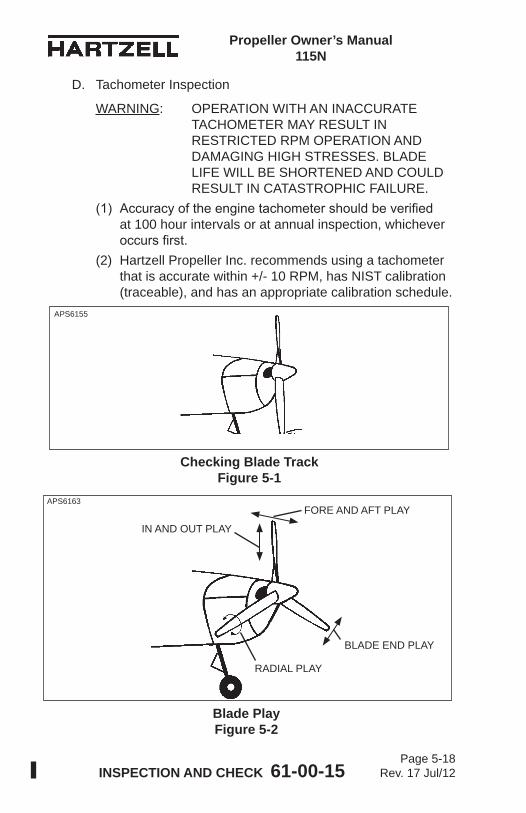
Propeller Owner’s Manual 115N
INSPECTION AND CHECK 61-00-15 Page 5-18
Rev. 17 Jul/12
D. Tachometer Inspection
WARNING: OPERATION WITH AN INACCURATE TACHOMETER MAY RESULT IN RESTRICTED RPM OPERATION AND DAMAGING HIGH STRESSES. BLADE LIFE WILL BE SHORTENED AND COULD RESULT IN CATASTROPHIC FAILURE.
(1) Accuracy of the engine tachometer should be verified at 100 hour intervals or at annual inspection, whichever occurs first.
(2) Hartzell Propeller Inc. recommends using a tachometer that is accurate within +/- 10 RPM, has NIST calibration (traceable), and has an appropriate calibration schedule.
APS6155
Checking Blade Track Figure 5-1
Blade Play Figure 5-2
APS6163
BLADE END PLAY
IN AND OUT PLAY
RADIAL PLAY
FORE AND AFT PLAY

Propeller Owner’s Manual 115N
INSPECTION AND CHECK 61-00-15 Page 5-19
Rev. 17 Jul/12
E. Blade Track(1) Check blade track as follows:
(a) Chock the aircraft wheels securely.(b) Refer to Figure 5-1. Place a fixed reference point
beneath the propeller, within 0.25 inch (6.0 mm) of the lowest point of the propeller arc. NOTE: This reference point may be a flat board
with a sheet of paper attached to it. The board may then be blocked up to within 0.25 inch (6.0 mm) of the propeller arc.
WARNING: MAKE SURE THE ENGINE MAGNETO IS GROUNDED (OFF) BEFORE ROTATING THE PROPELLER.
(c) Rotate the propeller by hand (opposite the direction of normal rotation) until a blade points directly at the reference surface (paper). 1 If the propeller does not have a start lock and
blade track must be checked when the propeller is in feather position:a Put a spirit level or blade protractor against
the flat side of the blade counterweight.b Slightly rotate the propeller blade until
the level or protractor indicates the blade counterweight is perpendicular with the reference surface (paper).
(d) Mark the position of the blade tip in relation to the reference surface (paper).
(e) Repeat this procedure with the remaining blades.(f) Tracking tolerance is ± 0.062 inch (1.57 mm) or
0.125 inch (3.17 mm) total.(2) Possible Correction
(a) Remove foreign matter from the propeller mounting flange.
(b) If no foreign matter is present, refer to an appropriately licensed propeller repair facility.
Propeller Owner’s Manual 115N
INSPECTION AND CHECK 61-00-15 Page 5-20
Rev. 17 Jul/12
F. Loose BladesRefer to Figure 5-2. Limits for blade looseness are as follows:End Play (leading edge to trailing edge) See Note below Fore & Aft Movement (Face to camber See Note below In & Out None Radial Play (pitch change) ± 0.5 degree (1 degree total) measured at reference stationNOTE: Blades are intended to be tight in the propeller,
however slight movement is acceptable if the blade returns to its original position when released. Blades with excessive movement, or that do not return to their original position when released may indicate internal wear or damage which should be referred to an appropriately licensed propeller repair facility.
G. Corrosion
WARNING: REWORK THAT INVOLVES COLD WORKING THE METAL, RESULTING IN CONCEALMENT OF A DAMAGED AREA IS NOT PERMITTED.
(1) Light corrosion on the blades or counterweights may be removed by qualified personnel in accordance with the Blade Repairs section in the Maintenance Practices chapter of this manual.
(2) Heavy corrosion that results in severe pitting must be referred to an appropriately licensed propeller repair facility.
Propeller Owner’s Manual 115N
INSPECTION AND CHECK 61-00-15 Page 5-21
Rev. 17 Jul/12
H. Spinner Damage(1) Inspect the spinner for cracks, missing hardware, or
other damage. (a) For metal spinners, refer to Hartzell Propeller
Inc. Manual 127 (61-16-27) or an appropriately licensed propeller repair facility for spinner damage acceptance and repair information. Contact the local airworthiness authority for repair approval.
(b) For composite spinners, refer to Hartzell Propeller Inc. Manual 148 (61-16-48) or an appropriately licensed propeller repair facility for spinner damage acceptance and repair information. Contact the local airworthiness authority for repair approval.
I. Electric De-ice System(1) Refer to the Anti-ice and De-ice Systems chapter of this
manual for inspection procedures.J. Anti-ice System
(1) Refer to the Anti-ice and De-ice Systems chapter of this manual for inspection procedures.
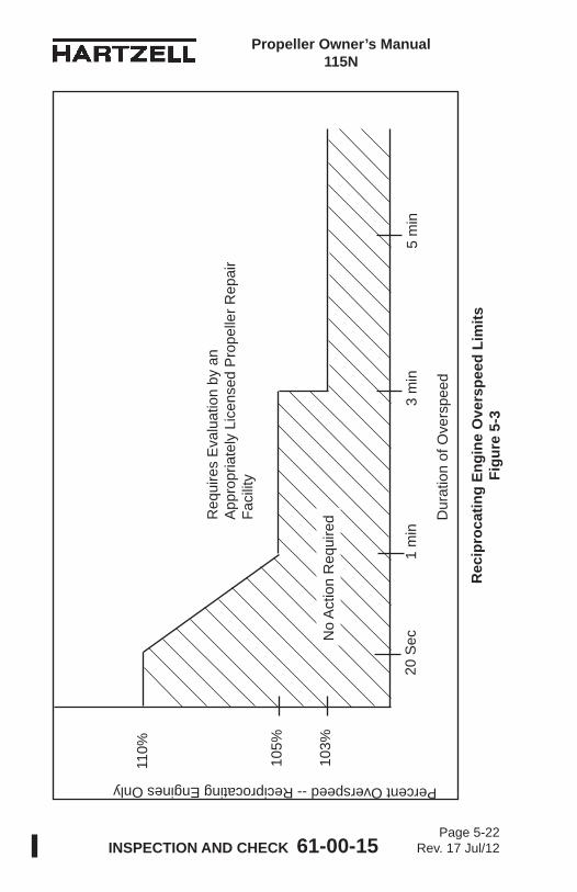
Propeller Owner’s Manual 115N
INSPECTION AND CHECK 61-00-15 Page 5-22
Rev. 17 Jul/12
Percent Overspeed -- Reciprocating Engines Only
Rec
ipro
catin
g En
gine
Ove
rspe
ed L
imits
Figu
re 5
-3
Dur
atio
n of
Ove
rspe
ed
105%
20 S
ec1
min
3 m
in5
min
110%
103%
Req
uire
s E
valu
atio
n by
an
App
ropr
iate
ly L
icen
sed
Pro
pelle
r Rep
air
Faci
lity
No
Act
ion
Req
uire
d
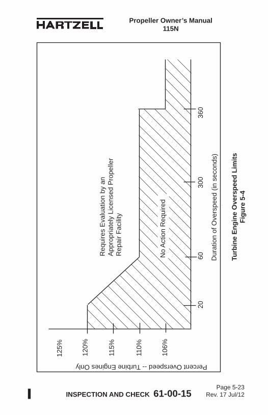
Propeller Owner’s Manual 115N
INSPECTION AND CHECK 61-00-15 Page 5-23
Rev. 17 Jul/12
Turb
ine
Engi
ne O
vers
peed
Lim
itsFi
gure
5-4
Percent Overspeed -- Turbine Engines Only
110%
Dur
atio
n of
Ove
rspe
ed in
Sec
onds
115%
120%
106%
6030
0 3
60
125%
20
Req
uire
s E
valu
atio
n by
an
App
ropr
iate
ly L
icen
sed
Pro
pelle
r R
epai
r Fac
ility
Dur
atio
n of
Ove
rspe
ed (i
n se
cond
s)
No
Act
ion
Req
uire
d
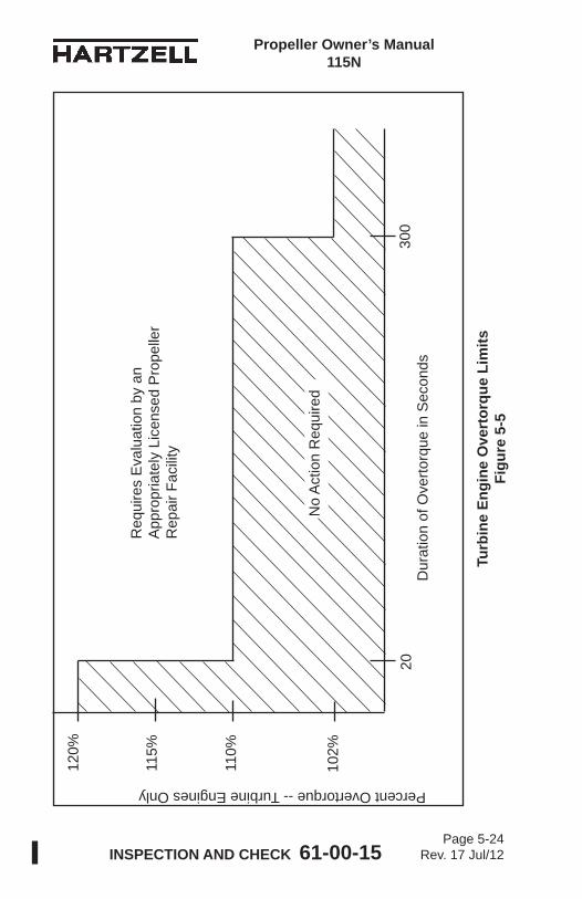
Propeller Owner’s Manual 115N
INSPECTION AND CHECK 61-00-15 Page 5-24
Rev. 17 Jul/12
Turb
ine
Engi
ne O
vert
orqu
e Li
mits
Figu
re 5
-5
Percent Overtorque -- Turbine Engines Only
110%
115%
120%
300
20
102%
Dur
atio
n of
Ove
rtorq
ue in
Sec
onds
Req
uire
s E
valu
atio
n by
an
App
ropr
iate
ly L
icen
sed
Pro
pelle
r R
epai
r Fac
ility
No
Act
ion
Req
uire
d
Propeller Owner’s Manual 115N
INSPECTION AND CHECK 61-00-15 Page 5-25
Rev. 17 Jul/12
6. Special Inspections
CAUTION: INSTRUCTIONS AND PROCEDURES IN THIS SECTION MAY INVOLVE PROPELLER CRITICAL PARTS. REFER TO THE INTRODUCTION CHAPTER OF THIS MANUAL FOR INFORMATION ABOUT PROPELLER CRITICAL PARTS. REFER TO THE ILLUSTRATED PARTS LIST CHAPTER OF THE APPLICABLE OVERHAUL MANUAL(S) FOR THE IDENTIFICATION OF SPECIFIC PROPELLER CRITICAL PARTS.
A. Overspeed/OvertorqueAn overspeed occurrs when the propeller RPM exceeds the maximum RPM stated in the applicable Aircraft Type Certificate Data Sheet. An overtorque condition occurs when the engine load exceeds the limits established by the engine, propeller, or airframe manufacturer. The duration of time at overspeed/overtorque for a single event determines the corrective action that must be taken to make sure no damage to the propeller has occurred.The criteria for determining the required action after an overspeed are based on many factors. The additional centrifugal forces that occur during overspeed are not the only concern. Some applications have sharp increases in vibratory stresses at RPMs above the maximum rated for the airframe/engine/propeller combination.(1) When a propeller installed on a reciprocating engine has
an overspeed event, refer to the Reciprocating Engine Overspeed Limits (Figure 5-3) to determine the corrective action to be taken.
(2) When a propeller installed on a turbine engine has an overspeed event, refer to the Turbine Engine Overspeed Limits (Figure 5-4) to determine the corrective action to be taken.
(3) When a propeller installed on a turbine engine has an overtorque event, refer to the Turbine Engine Overtorque Limits (Figure 5-5) to determine the corrective action to be taken.
(4) Make an entry in the propeller logbook about the overspeed/overtorque event.
Propeller Owner’s Manual 115N
INSPECTION AND CHECK 61-00-15 Page 5-26
Rev. 17 Jul/12
B. Lightning Strike
CAUTION: ALSO CONSULT ENGINE AND AIRFRAME MANUFACTURER'S MANUALS. THERE MAY BE ADDITIONAL REQUIREMENTS SUCH AS DE-ICE AND ENGINE SYSTEM CHECKS TO PERFORM AFTER A PROPELLER LIGHTNING STRIKE.
(1) General(a) In the event of a propeller lightning strike, an
inspection is required before further flight. It may be permissible for a propeller to be operated for an additional ten (10) hours if the propeller is not severely damaged and meets the requirements in paragraph 5.B.(2).
(b) Regardless of the outcome of the initial inspection, the propeller must be removed from the aircraft, disassembled, evaluated, and/or repaired by an appropriately licensed propeller repair facility.
(2) Procedure for Temporary OperationIf temporary additional operation is desired before propeller removal and disassembly:(a) Remove spinner dome and perform visual inspection
of propeller, spinner, and de-ice system for evidence of significant damage that would require repair before flight (such as broken de-ice wires or arcing damage to propeller hub).
CAUTION: IF THE PROPELLER EXPERIENCES A LIGHTNING STRIKE,THE ALUMINUM BLADES MUST BE WITHIN AIRWORTHY LIMITS FOR ANY ADDITIONAL FLIGHT.
(b) If the only evident damage is slight arcing burns to the blades, then operation for ten (10) hours is acceptable before disassembly and inspection.
(c) Perform a functional check of the propeller de- ice system (if installed) in accordance with aircraft maintenance manual procedures.
Propeller Owner’s Manual 115N
INSPECTION AND CHECK 61-00-15 Page 5-27
Rev. 17 Jul/12
(d) Regardless of the degree of damage, make an entry in the propeller logbook about the lightning strike.
(e) The propeller must be removed from the aircraft, disassembled, evaluated, and/or repaired by an appropriately licensed propeller repair facility for flight beyond the temporary operation limits granted above.
C. Foreign Object Strike(1) General
(a) A foreign object strike can include a broad spectrum of damage, from a minor stone nick to severe ground impact damage. A conservative approach in evaluating the damage is required because there may be hidden damage that is not readily apparent during an on-wing, visual inspection.
(b) A foreign object strike is defined as:1 Any incident, whether or not the engine is
operating, that requires repair to the propeller other than minor dressing of the blades. Examples of foreign object strike include situations where an aircraft is stationary and the landing gear collapses causing one or more blades to be significantly damaged, or where a hangar door (or other object) strikes the propeller blade. These cases should be handled as foreign object strikes because of potentially severe side loading on the propeller hub, blades and retention bearings.
2 Any incident during engine operation in which the propeller impacts a solid object that causes a drop in revolutions per minute (RPM) and also requires structural repair of the propeller (incidents requiring only paint touch-up are not included). This is not restricted to propeller strikes against the ground.
3 A sudden RPM drop while impacting water, tall grass, or similar yielding medium, where propeller blade damage is not normally incurred.
Propeller Owner’s Manual 115N
INSPECTION AND CHECK 61-00-15 Page 5-28
Rev. 17 Jul/12
(2) Procedure(a) In the event of a foreign object strike, an inspection is
required before further flight. If the inspection reveals one or more of the following indications, the propeller must be removed from the aircraft, disassembled and overhauled in accordance with the applicable propeller and blade maintenance manuals.1 A loose blade in the hub.2 Any noticeable or suspected damage to the pitch
change mechanism. 3 A bent blade (out of track or angle).4 Any blade diameter reduction.5 A bent, cracked, or failed engine shaft.6 Vibration during operation that was not present
before the event.(b) Nicks, gouges, and scratches on blade surfaces
or the leading and trailing edges must be removed before flight. Refer to the Blade Repairs section in the Maintenance Practices chapter of this manual.
(c) For engine mounted accessories - for example, governors, pumps, and propeller control units manufactured by Hartzell Propeller Inc. - if the foreign object strike resulted in a sudden stop of the engine, the unit must be disassembled and inspected in accordance with the applicable maintenance manual.
(d) Regardless of the degree of damage, make a log book entry to document the foreign object strike incident and any corrective action(s) taken.
Propeller Owner’s Manual 115N
INSPECTION AND CHECK 61-00-15 Page 5-29
Rev. 17 Jul/12
D. Fire Damage or Heat Damage
WARNING: HUBS ARE MANUFACTURED FROM HEAT TREATED FORGINGS AND ARE SHOT PEENED. BLADES ARE MANUFACTURED FROM HEAT TREATED FORGINGS AND ARE COMPRESSIVELY ROLLED AND SOMETIMES SHOT PEENED. EXPOSURE TO HIGH TEMPERATURES CAN DESTROY THE FATIGUE BENEFITS OBTAINED FROM THESE PROCESSES.
(1) On rare occasions propellers may be exposed to fire or heat damage such as an engine or hangar fire. In the event of such an incident, an inspection by an appropriately licensed propeller repair facility is required before further flight.
7. Long Term StorageA. Parts shipped from the Hartzell Propeller Inc. factory are not
shipped or packaged in a container that is designed for long term storage.
B. Long term storage procedures may be obtained by contacting a Hartzell Propeller Inc. distributor, or the Hartzell Propeller Inc. factory via the Product Support number listed in the Introduction chapter of this manual. Storage information is also detailed in Hartzell Propeller Inc. Standard Practices Manual 202A (61-01-02).
C. Information regarding the return of a propeller assembly to service after long term storage may be obtained by contacting a Hartzell Propeller Inc. distributor, or the Hartzell Propeller Inc. factory via the Product Support number listed in the Introduction chapter of this manual. This information is also detailed in Hartzell Propeller Inc. Standard Practices Manual 202A (61-01-02).
Propeller Owner’s Manual 115N
INSPECTION AND CHECK 61-00-15 Page 5-30
Rev. 17 Jul/12
(This page is intentionally blank.)
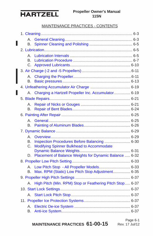
MAINTENANCE PRACTICES 61-00-15 Page 6-1
Rev. 17 Jul/12
Propeller Owner's Manual 115N
MAINTENANCE PRACTICES - CONTENTS
1. Cleaning ..................................................................................... 6-3A. General Cleaning ............................................................... 6-3B. Spinner Cleaning and Polishing ........................................ 6-5
2. Lubrication .................................................................................. 6-5A. Lubrication Intervals .......................................................... 6-5B. Lubrication Procedure ....................................................... 6-7C. Approved Lubricants ........................................................ 6-10
3. Air Charge (-2 and -5 Propellers) ..............................................6-11A. Charging the Propeller ......................................................6-11B. Basic pressures ............................................................... 6-13
4. Unfeathering Accumulator Air Charge ..................................... 6-19A. Charging a Hartzell Propeller Inc. Accumulator ............... 6-19
5. Blade Repairs ........................................................................... 6-21A. Repair of Nicks or Gouges .............................................. 6-21B. Repair of Bent Blades ...................................................... 6-24
6. Painting After Repair ................................................................ 6-25A. General ............................................................................ 6-25B. Painting of Aluminum Blades ........................................... 6-26
7. Dynamic Balance ..................................................................... 6-29A. Overview .......................................................................... 6-29B. Inspection Procedures Before Balancing ........................ 6-30C. Modifying Spinner Bulkhead to Accommodate
Dynamic Balance Weights ............................................... 6-31D. Placement of Balance Weights for Dynamic Balance ..... 6-32
8. Propeller Low Pitch Setting ...................................................... 6-33A. Low Pitch Stop - All Propeller Models ............................. 6-33B. Max. RPM (Static) Low Pitch Stop Adjustment ................ 6-35
9. Propeller High Pitch Settings ................................................... 6-37A. High Pitch (Min. RPM) Stop or Feathering Pitch Stop ..... 6-37
10. Start Lock Settings ................................................................. 6-37A. Start Lock Pitch Stop ....................................................... 6-37
11. Propeller Ice Protection Systems ........................................... 6-37A. Electric De-ice System .................................................... 6-37B. Anti-ice System ................................................................ 6-37
MAINTENANCE PRACTICES 61-00-15 Page 6-2
Rev. 17 Jul/12
Propeller Owner's Manual 115N
LIST OF FIGURESLubrication Fitting and Air Charge
Valve Location ........................................... Figure 6-1 .............6-4Lubrication Fitting ............................................ Figure 6-2 .............6-6Lubrication Label ............................................. Figure 6-3 .............6-8Counterweighted vs Non-Counterweighted
Blades ....................................................... Figure 6-4 ...........6-12Unfeathering Accumulator ............................... Figure 6-5 ...........6-18Repair Limitations ............................................ Figure 6-6 ...........6-22Low Pitch Stop Adjustment (-1, -4) .................. Figure 6-7 ...........6-34Low Pitch Stop Adjustment (-2, -5) .................. Figure 6-8 ...........6-34
LIST OF TABLES
Air Charge Pressure ......................................... Table 6-1 ............6-16Air Charge Pressure ......................................... Table 6-2 ............6-16Air Charge Pressure ......................................... Table 6-3 ............6-16Air Charge Pressure ......................................... Table 6-4 .........6-16.1Air Charge Pressure ......................................... Table 6-5 .........6-16.1Air Charge Pressure ......................................... Table 6-6 .........6-16.1Air Charge Pressure ......................................... Table 6-7 .........6-16.2Air Charge Pressure ......................................... Table 6-8 .........6-16.2Air Charge Pressure ......................................... Table 6-9 ............6-17Air Charge Pressure ........................................ Table 6-10 ...........6-17Accumulator Air Charge Pressure ................... Table 6-11 ...........6-19Approved Touch-up Paints .............................. Table 6-12 ...........6-24
MAINTENANCE PRACTICES 61-00-15 Page 6-3
Rev. 17 Jul/12
Propeller Owner's Manual 115N
1. Cleaning
CAUTION 1: INSTRUCTIONS AND PROCEDURES IN THIS SECTION MAY INVOLVE PROPELLER CRITICAL PARTS. REFER TO THE INTRODUCTION CHAPTER OF THIS MANUAL FOR INFORMATION ABOUT PROPELLER CRITICAL PARTS. REFER TO THE ILLUSTRATED PARTS LIST CHAPTER OF THE APPLICABLE OVERHAUL MANUAL(S) FOR THE IDENTIFICATION OF SPECIFIC PROPELLER CRITICAL PARTS.
CAUTION 2: DO NOT USE PRESSURE WASHING EQUIPMENT TO CLEAN THE PROPELLER OR CONTROL COMPONENTS. PRESSURE WASHING CAN FORCE WATER AND/OR CLEANING FLUIDS PAST SEALS AND LEAD TO INTERNAL CORROSION OF PROPELLER COMPONENTS.
A. General Cleaning
CAUTION 1: WHEN CLEANING THE PROPELLER, DO NOT PERMIT SOAP OR SOLVENT SOLUTIONS TO RUN OR SPLASH INTO THE HUB AREA.
CAUTION 2: DO NOT CLEAN PROPELLER WITH CAUSTIC OR ACIDIC SOAP SOLUTIONS. IRREPARABLE CORROSION OF PROPELLER COMPONENTS MAY OCCUR.
CAUTION 3: DO NOT USE ANY SOLVENT DURING CLEANING THAT COULD SOFTEN OR DESTROY THE BOND BETWEEN CHEMICALLY ATTACHED PARTS.
(1) To remove grease or oil from propeller surfaces, apply Stoddard Solvent or equivalent to a clean cloth and wipe the part clean.
(2) Using a noncorrosive soap solution, wash the propeller.(3) Thoroughly rinse with water.(4) Permit to dry.
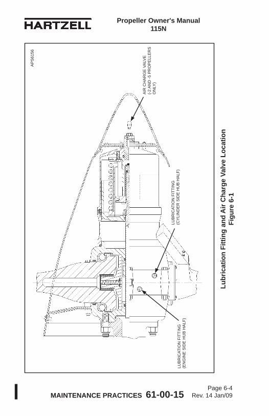
MAINTENANCE PRACTICES 61-00-15 Page 6-4
Rev. 14 Jan/09
Propeller Owner's Manual 115N
Lubr
icat
ion
Fitti
ng a
nd A
ir C
harg
e Va
lve
Loca
tion
Figu
re 6
-1
LUB
RIC
ATIO
N F
ITTI
NG
(C
YLI
ND
ER
SID
E H
UB
HA
LF)
AIR
CH
AR
GE
VA
LVE
(-
2 A
ND
-5 P
RO
PE
LLE
RS
O
NLY
)
LUB
RIC
ATIO
N F
ITTI
NG
(E
NG
INE
SID
E H
UB
HA
LF)
AP
S61
56
MAINTENANCE PRACTICES 61-00-15 Page 6-5
Rev. 17 Jul/12
Propeller Owner's Manual 115N
B. Spinner Cleaning and Polishing(1) Clean spinner using the General Cleaning procedures
above.(2) Polish the dome, if necessary, with an automotive-type
aluminum polish.
2. Lubrication
CAUTION 1: INSTRUCTIONS AND PROCEDURES IN THIS SECTION MAY INVOLVE PROPELLER CRITICAL PARTS. REFER TO THE INTRODUCTION CHAPTER OF THIS MANUAL FOR INFORMATION ABOUT PROPELLER CRITICAL PARTS. REFER TO THE ILLUSTRATED PARTS LIST CHAPTER OF THE APPLICABLE OVERHAUL MANUAL(S) FOR THE IDENTIFICATION OF SPECIFIC PROPELLER CRITICAL PARTS.
A. Lubrication Intervals(1) The propeller must be lubricated at intervals not to
exceed 100 hours or at 12 calendar months, whichever occurs first.(a) If annual operation is significantly less than 100
hours, calendar lubrication intervals should be reduced to six months.
(b) If the aircraft is operated or stored under adverse atmospheric conditions, e.g., high humidity, salt air, calendar lubrication intervals should be reduced to six months.
(2) Owners of high use aircraft may wish to extend their lubrication interval. Lubrication interval may be gradually extended after evaluation of previous propeller overhauls with regard to bearing wear and internal corrosion.
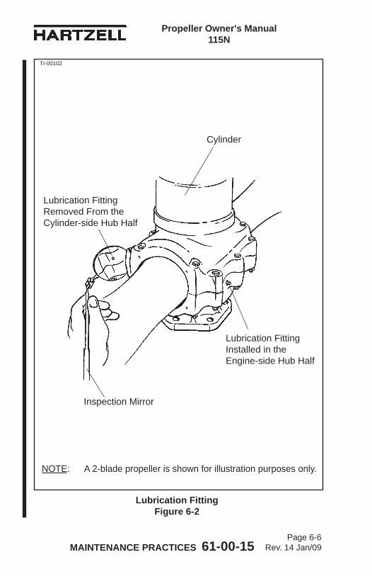
MAINTENANCE PRACTICES 61-00-15 Page 6-6
Rev. 14 Jan/09
Propeller Owner's Manual 115N
Lubrication Fitting Figure 6-2
Lubrication Fitting Removed From the Cylinder-side Hub Half
Lubrication Fitting Installed in the Engine-side Hub Half
TI-00102
NOTE: A 2-blade propeller is shown for illustration purposes only.
Cylinder
Inspection Mirror

MAINTENANCE PRACTICES 61-00-15 Page 6-7
Rev. 17 Jul/12
Propeller Owner's Manual 115N
(3) Hartzell Propeller Inc. recommends that new or newly overhauled propellers be lubricated after the first one or two hours of operation because centrifugal loads will pack and redistribute grease, which may result in a propeller imbalance. Redistribution of grease may also result in voids in the blade bearing area where moisture can collect.1 Purchasers of new aircraft should check the propeller
logbook to verify whether the propeller was lubricated by the manufacturer during flight testing. If it was not lubricated, the propeller should be serviced at the earliest convenience.
B. Lubrication Procedure
WARNING 1: FOLLOW LUBRICATION PROCEDURES CORRECTLY TO MAINTAIN AN ACCURATE BALANCE OF THE PROPELLER ASSEMBLY.
WARNING 2: PITCH CONTROL DIFFICULTY COULD RESULT IF THE PROPELLER IS NOT CORRECTLY LUBRICATED.
(1) Remove the propeller spinner.(2) Refer to Figure 6-1 and Figure 6-2. Each blade socket has
two lubrication fittings. Remove the lubrication fitting caps from the lubrication fittings. Remove the lubrication fittings from either the cylinder-side or the engine-side of the hub assembly.(a) It is preferable to apply grease to the fitting located
nearest the leading edge of the blade on a tractor installation, or nearest the trailing edge on a pusher installation. Lubricating at this location reduces the possibility of grease bypassing the bearing area and entering the hub cavity.
(b) Some propellers use an internal blade seal that prevents grease from entering the hub cavity. Because this seal is very efficient, it is important to remove the opposite lubrication fitting. Pitch control difficulty could result if the propeller is not correctly lubricated.
(3) Using a piece of safety wire, loosen any blockage orhardened grease at the threaded holes where the lubrication fitting was removed.
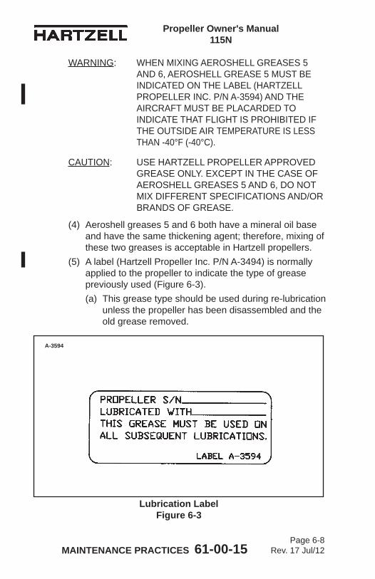
MAINTENANCE PRACTICES 61-00-15 Page 6-8
Rev. 17 Jul/12
Propeller Owner's Manual 115N
WARNING: WHEN MIXING AEROSHELL GREASES 5 AND 6, AEROSHELL GREASE 5 MUST BE INDICATED ON THE LABEL (HARTZELL PROPELLER INC. P/N A-3594) AND THE AIRCRAFT MUST BE PLACARDED TO INDICATE THAT FLIGHT IS PROHIBITED IF THE OUTSIDE AIR TEMPERATURE IS LESS THAN -40°F (-40°C).
CAUTION: USE HARTZELL PROPELLER APPROVED GREASE ONLY. EXCEPT IN THE CASE OF AEROSHELL GREASES 5 AND 6, DO NOT MIX DIFFERENT SPECIFICATIONS AND/OR BRANDS OF GREASE.
(4) Aeroshell greases 5 and 6 both have a mineral oil base and have the same thickening agent; therefore, mixing of these two greases is acceptable in Hartzell propellers.
(5) A label (Hartzell Propeller Inc. P/N A-3494) is normally applied to the propeller to indicate the type of grease previously used (Figure 6-3). (a) This grease type should be used during re-lubrication
unless the propeller has been disassembled and the old grease removed.
Lubrication Label Figure 6-3
A-3594
MAINTENANCE PRACTICES 61-00-15 Page 6-9
Rev. 17 Jul/12
Propeller Owner's Manual 115N
(b) Purging of old grease through lubrication fittings is only about 30 percent effective.
(c) To completely replace one grease with another, the propeller must be disassembled in accordance with the applicable overhaul manual.
CAUTION 1: OVER LUBRICATING AN ALUMINUM HUB PROPELLER MAY CAUSE THE GREASE TO ENTER THE HUB CAVITY, LEADING TO EXCESSIVE VIBRATION AND/OR SLUGGISH OPERATION. THE PROPELLER MUST THEN BE DISASSEMBLED TO REMOVE THIS GREASE.
CAUTION 2: IF A PNEUMATIC GREASE GUN IS USED, EXTRA CARE MUST BE TAKEN TO AVOID EXCESSIVE PRESSURE BUILDUP.
CAUTION 3: GREASE MUST BE APPLIED TO ALL BLADES OF A PROPELLER ASSEMBLY AT THE TIME OF LUBRICATION.
(6) Pump 1 fl. oz. (30 ml) grease into the fitting located nearest the leading edge of the blade on a tractor installation, or nearest the trailing edge on a pusher installation, or until grease emerges from the hole where the fitting was removed - whichever occurs first. NOTE: 1 fl. oz. (30 ml) is approximately 6 pumps with
a hand-operated grease gun.(7) Reinstall the removed lubrication fittings. Tighten the
fittings until snug.(a) Make sure that the ball of each lubrication fitting is
properly seated.(8) Reinstall a lubrication fitting cap on each lubrication
fitting.
MAINTENANCE PRACTICES 61-00-15 Page 6-10
Rev. 17 Jul/12
Propeller Owner's Manual 115N
C. Approved Lubricants(1) The following lubricants are approved for use in Hartzell
Propeller Inc. compact propellers:Aeroshell 6 - Recommended "all purpose" grease.
Used in most new production propellers since 1989. Higher leakage/oil separation than Aeroshell 5 at higher temperatures (approximately 100°F [38°C]).
Aeroshell 5 - Good high temperature qualities, very little oil separation or leakage. Cannot be used in temperatures colder than -40°F (-40°C). Aircraft serviced with this grease must be placarded to indicate that flight is prohibited if the outside air temperature is less than -40°F (-40°C).
Aeroshell 7 - Good low temperature grease, but high leakage/oil separation at higher temperatures. This grease has been associated with sporadic problems involving seal swelling.
Aeroshell 22 - Qualities similar to Aeroshell 7. Royco 22CF - Not widely used. Qualities similar to
Aeroshell 22.
MAINTENANCE PRACTICES 61-00-15 Page 6-11
Rev. 17 Jul/12
Propeller Owner's Manual 115N
3. Air Charge (-2 and -5 Propellers)
CAUTION 1: INSTRUCTIONS AND PROCEDURES IN THIS SECTION MAY INVOLVE PROPELLER CRITICAL PARTS. REFER TO THE INTRODUCTION CHAPTER OF THIS MANUAL FOR INFORMATION ABOUT PROPELLER CRITICAL PARTS. REFER TO THE ILLUSTRATED PARTS LIST CHAPTER OF THE APPLICABLE OVERHAUL MANUAL(S) FOR THE IDENTIFICATION OF SPECIFIC PROPELLER CRITICAL PARTS.
A. Charging the PropellerWARNING: EXCEPT FOR THE HC-C3YF-5F
PROPELLER, DO NOT AIR CHARGE THE CYLINDER OR MEASURE THE AIR CHARGE ON A PROPELLER THAT IS IN FEATHER POSITION.
(1) Examine the propeller to make sure that it is positioned on the start locks.
(2) Using proper control, charge the cylinder with dry air or nitrogen. (a) The air charge valve is located on the cylinder as
indicated in Figure 6-1.(b) Nitrogen is the preferred charging medium. CAUTION: MAKE SURE THAT THE GAUGE IS
CALIBRATED BEFORE CHARGING THE CYLINDER OR MEASURING THE AIR PRESSURE.
(c) Use an appropriate tool that has a calibrated gauge to charge the cylinder or measure air pressure in the propeller.
(d) The correct charge pressure is identified in Table 6-1 through Table 6-8 in this chapter.
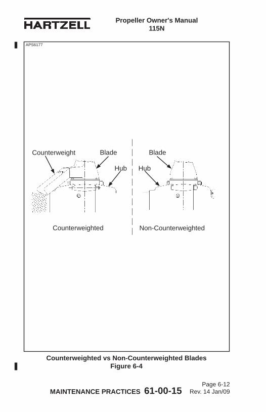
MAINTENANCE PRACTICES 61-00-15 Page 6-12
Rev. 14 Jan/09
Propeller Owner's Manual 115N
Counterweighted vs Non-Counterweighted Blades Figure 6-4
APS6177
Non-CounterweightedCounterweighted
Hub
Counterweight Blade
Hub
Blade
APS6177
MAINTENANCE PRACTICES 61-00-15 Page 6-13
Rev. 17 Jul/12
Propeller Owner's Manual 115N
(3) The following instructions may be used to determine the correct pressure. (a) To use these instructions, the propeller model number
must be known, and it must be determined if the propeller blades are counterweighted.
(b) The propeller model number is recorded in the log book, and is also stamped on the propeller hub. The propeller model number indicates the presence of a spring kit by an "S," "U," or "T" after the dash number. For example: HC-C3YR-2LUF indicates a "U" spring kit.
(c) To determine if the blades are counterweighted, remove the spinner dome and examine the base of the blade. Compare the blades to those shown in the Figure 6-4.
B. Basic pressures:NOTE: Propellers on certain aircraft and engine combinations
have experienced instances of inadvertant feathering. These events occurred either at the time of shut down or at low engine RPM. Hartzell Propeller Inc. has determined that this tendency to feather may be reduced or eliminated by lowering the air charge within the propeller cylinder. Those propellers authorized for operation with a reduced air charge are listed in this section.
(1) All four-blade compact propellers - Table 6-5Except: HC-C4YR-2(L)/F(J)C7663DB-6Q - Table 6-6
(2) All propellers with no counterweights and no spring - Table 6-1
(3) All propellers with no counterweights and an “S” spring - Table 6-2Except: HC-E2Y(K,R)-2RBS( ) - Table 6-3
MAINTENANCE PRACTICES 61-00-15 Page 6-14
Rev. 17 Jul/12
Propeller Owner's Manual 115N
(4) All propellers with counterweights and no spring - Table 6-4Except: BHC-C2YF-2CKF/FC8459-8R(B) or BHC-C2YF-2CLKF/FJC8459-8R(B) when installed on the Piper PA-34-200T with Continental TSIO-360-E(B) or LTSIO- 360-(B) engines - Refer to Table 6-10.
NOTE: For BHC-C2YF-2CKF/FC8459-8R(B) or BHC-C2YF-2CLKF/FJC8459-8R(B) model propellers that have been upgraded with the installation of a feather assist spring - Refer to Table 6-6.
NOTE: Propeller models indicated by * in the exceptions below have a "U" spring installed, which is not indicated in the part number.
Except: HC-C3YF-5F* - Table 6-8 HC-C3YN-5A* - Table 6-5 HC-H3YF-3LF - Table 6-4 PHC-I3YF-2AL* - Table 6-5 PHC-J3YF-2(F) - Table 6-9
(5) All propellers with counterweights and a “T” spring -Table 6-5 Except: HC-E3YR-2ATF on Fuji Model 700
Commander - Table 6-7(6) All propellers with counterweights and a “U” spring -
Table 6-5 Except: See Note under (4), above. (B)HC-C2YF-2(C)(L)(K)U( ) - Table 6-6 PHC-C3YF-2(L)KUF - Table 6-6 PHC-H3YF-2KUF when installed on the Avia Accord - Refer to Table 6-6. PHC-C3YF-2UF/FC7663( )-2R when installed on the Beech 95-(A,B)55(A,B) Baron with IO-470-L engines - Refer to Table 6-6. HC-C2YL-2CUF/FC7663-4 when installed on the Piper PA-23, PA-23-160 with O-320 engines - Refer to Table 6-6.
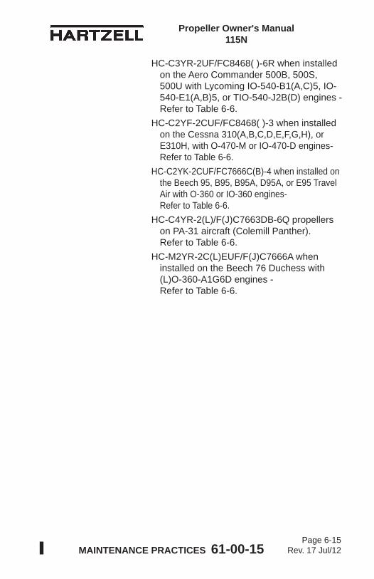
MAINTENANCE PRACTICES 61-00-15 Page 6-15
Rev. 17 Jul/12
Propeller Owner's Manual 115N
HC-C3YR-2UF/FC8468( )-6R when installed on the Aero Commander 500B, 500S, 500U with Lycoming IO-540-B1(A,C)5, IO- 540-E1(A,B)5, or TIO-540-J2B(D) engines - Refer to Table 6-6. HC-C2YF-2CUF/FC8468( )-3 when installed on the Cessna 310(A,B,C,D,E,F,G,H), or E310H, with O-470-M or IO-470-D engines- Refer to Table 6-6. HC-C2YK-2CUF/FC7666C(B)-4 when installed on the Beech 95, B95, B95A, D95A, or E95 Travel Air with O-360 or IO-360 engines- Refer to Table 6-6. HC-C4YR-2(L)/F(J)C7663DB-6Q propellers on PA-31 aircraft (Colemill Panther). Refer to Table 6-6. HC-M2YR-2C(L)EUF/F(J)C7666A when installed on the Beech 76 Duchess with (L)O-360-A1G6D engines - Refer to Table 6-6.
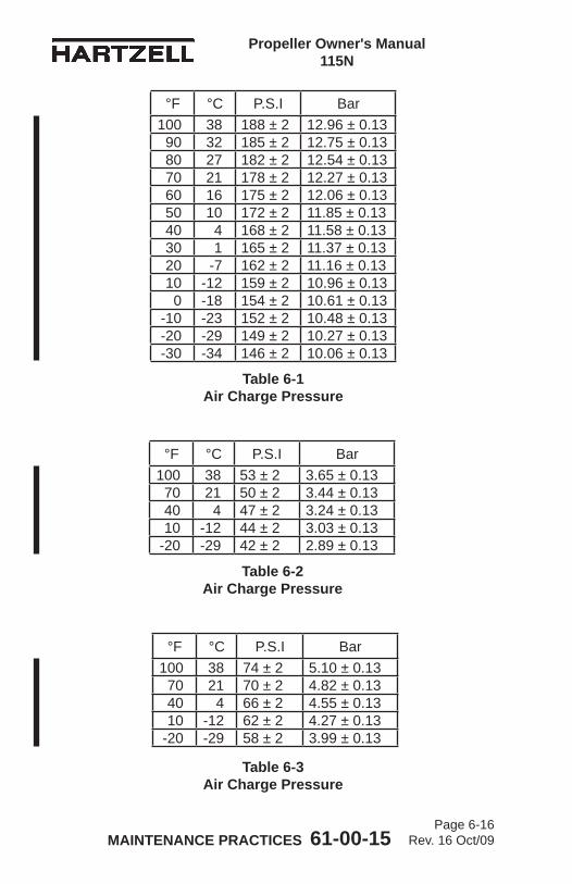
MAINTENANCE PRACTICES 61-00-15 Page 6-16
Rev. 16 Oct/09
Propeller Owner's Manual 115N
Table 6-1 Air Charge Pressure
°F °C P.S.I Bar100 38 188 ± 2 12.96 ± 0.1390 32 185 ± 2 12.75 ± 0.1380 27 182 ± 2 12.54 ± 0.1370 21 178 ± 2 12.27 ± 0.1360 16 175 ± 2 12.06 ± 0.1350 10 172 ± 2 11.85 ± 0.1340 4 168 ± 2 11.58 ± 0.1330 1 165 ± 2 11.37 ± 0.1320 -7 162 ± 2 11.16 ± 0.1310 -12 159 ± 2 10.96 ± 0.130 -18 154 ± 2 10.61 ± 0.13
-10 -23 152 ± 2 10.48 ± 0.13-20 -29 149 ± 2 10.27 ± 0.13-30 -34 146 ± 2 10.06 ± 0.13
Table 6-3 Air Charge Pressure
°F °C P.S.I Bar100 38 74 ± 2 5.10 ± 0.1370 21 70 ± 2 4.82 ± 0.1340 4 66 ± 2 4.55 ± 0.1310 -12 62 ± 2 4.27 ± 0.13
-20 -29 58 ± 2 3.99 ± 0.13
Table 6-2 Air Charge Pressure
°F °C P.S.I Bar100 38 53 ± 2 3.65 ± 0.1370 21 50 ± 2 3.44 ± 0.1340 4 47 ± 2 3.24 ± 0.1310 -12 44 ± 2 3.03 ± 0.13
-20 -29 42 ± 2 2.89 ± 0.13
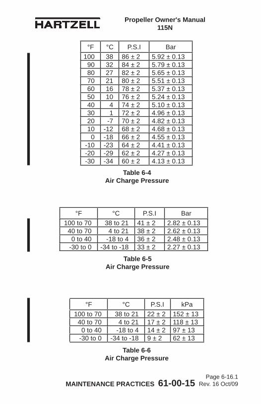
MAINTENANCE PRACTICES 61-00-15 Page 6-16.1
Rev. 16 Oct/09
Propeller Owner's Manual 115N
Table 6-4 Air Charge Pressure
°F °C P.S.I Bar100 38 86 ± 2 5.92 ± 0.1390 32 84 ± 2 5.79 ± 0.1380 27 82 ± 2 5.65 ± 0.1370 21 80 ± 2 5.51 ± 0.1360 16 78 ± 2 5.37 ± 0.1350 10 76 ± 2 5.24 ± 0.1340 4 74 ± 2 5.10 ± 0.1330 1 72 ± 2 4.96 ± 0.1320 -7 70 ± 2 4.82 ± 0.1310 -12 68 ± 2 4.68 ± 0.130 -18 66 ± 2 4.55 ± 0.13
-10 -23 64 ± 2 4.41 ± 0.13-20 -29 62 ± 2 4.27 ± 0.13-30 -34 60 ± 2 4.13 ± 0.13
Table 6-5 Air Charge Pressure
°F °C P.S.I Bar100 to 70 38 to 21 41 ± 2 2.82 ± 0.1340 to 70 4 to 21 38 ± 2 2.62 ± 0.130 to 40 -18 to 4 36 ± 2 2.48 ± 0.13
-30 to 0 -34 to -18 33 ± 2 2.27 ± 0.13
Table 6-6 Air Charge Pressure
°F °C P.S.I kPa100 to 70 38 to 21 22 ± 2 152 ± 13
40 to 70 4 to 21 17 ± 2 118 ± 130 to 40 -18 to 4 14 ± 2 97 ± 13
-30 to 0 -34 to -18 9 ± 2 62 ± 13
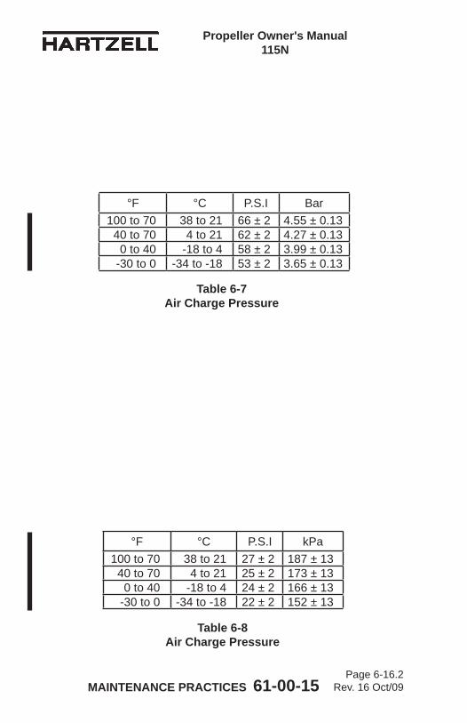
MAINTENANCE PRACTICES 61-00-15 Page 6-16.2
Rev. 16 Oct/09
Propeller Owner's Manual 115N
Table 6-7 Air Charge Pressure
°F °C P.S.I Bar100 to 70 38 to 21 66 ± 2 4.55 ± 0.13
40 to 70 4 to 21 62 ± 2 4.27 ± 0.130 to 40 -18 to 4 58 ± 2 3.99 ± 0.13
-30 to 0 -34 to -18 53 ± 2 3.65 ± 0.13
Table 6-8 Air Charge Pressure
°F °C P.S.I kPa100 to 70 38 to 21 27 ± 2 187 ± 13
40 to 70 4 to 21 25 ± 2 173 ± 130 to 40 -18 to 4 24 ± 2 166 ± 13
-30 to 0 -34 to -18 22 ± 2 152 ± 13
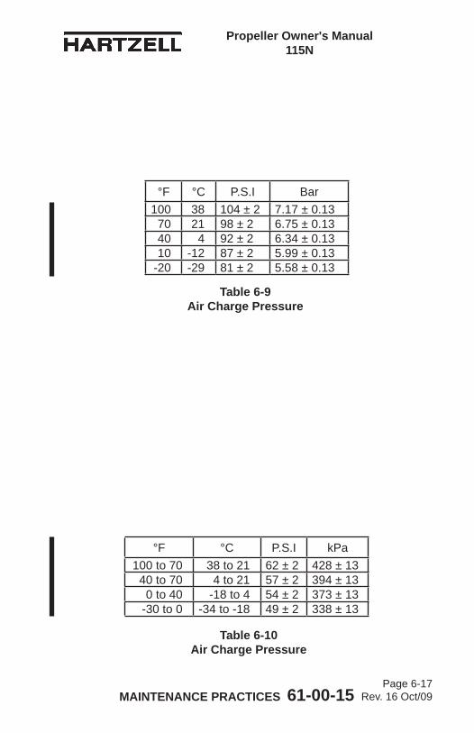
MAINTENANCE PRACTICES 61-00-15 Page 6-17
Rev. 16 Oct/09
Propeller Owner's Manual 115N
Table 6-9 Air Charge Pressure
°F °C P.S.I Bar100 38 104 ± 2 7.17 ± 0.1370 21 98 ± 2 6.75 ± 0.1340 4 92 ± 2 6.34 ± 0.1310 -12 87 ± 2 5.99 ± 0.13
-20 -29 81 ± 2 5.58 ± 0.13
Table 6-10 Air Charge Pressure
°F °C P.S.I kPa100 to 70 38 to 21 62 ± 2 428 ± 13
40 to 70 4 to 21 57 ± 2 394 ± 130 to 40 -18 to 4 54 ± 2 373 ± 13
-30 to 0 -34 to -18 49 ± 2 338 ± 13
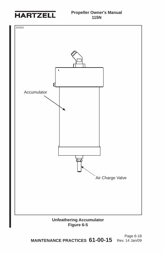
MAINTENANCE PRACTICES 61-00-15 Page 6-18
Rev. 14 Jan/09
Propeller Owner's Manual 115N
Unfeathering Accumulator Figure 6-5
Air Charge Valve
Accumulator
103161
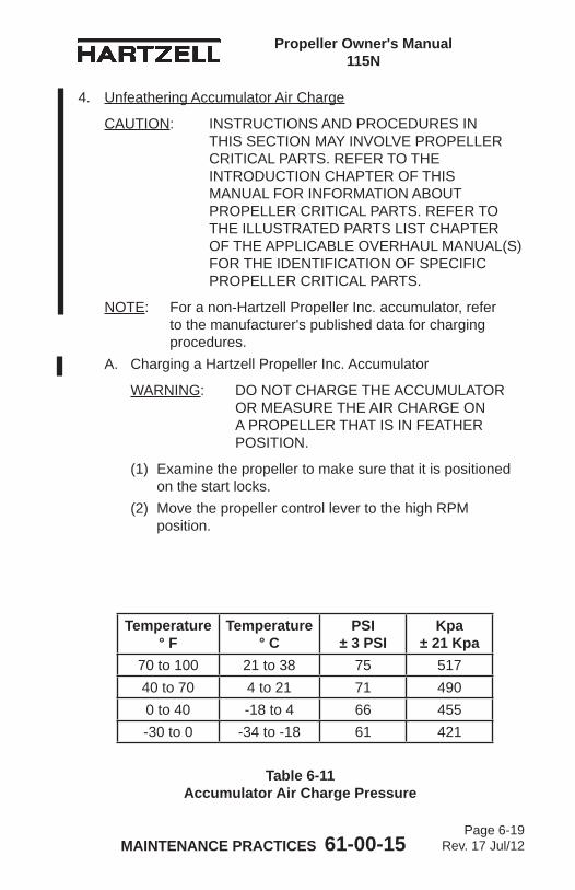
MAINTENANCE PRACTICES 61-00-15 Page 6-19
Rev. 17 Jul/12
Propeller Owner's Manual 115N
4. Unfeathering Accumulator Air Charge
CAUTION: INSTRUCTIONS AND PROCEDURES IN THIS SECTION MAY INVOLVE PROPELLER CRITICAL PARTS. REFER TO THE INTRODUCTION CHAPTER OF THIS MANUAL FOR INFORMATION ABOUT PROPELLER CRITICAL PARTS. REFER TO THE ILLUSTRATED PARTS LIST CHAPTER OF THE APPLICABLE OVERHAUL MANUAL(S) FOR THE IDENTIFICATION OF SPECIFIC PROPELLER CRITICAL PARTS.
NOTE: For a non-Hartzell Propeller Inc. accumulator, refer to the manufacturer's published data for charging procedures.
A. Charging a Hartzell Propeller Inc. Accumulator
WARNING: DO NOT CHARGE THE ACCUMULATOR OR MEASURE THE AIR CHARGE ON A PROPELLER THAT IS IN FEATHER POSITION.
(1) Examine the propeller to make sure that it is positioned on the start locks.
(2) Move the propeller control lever to the high RPM position.
Temperature° F
Temperature° C
PSI ± 3 PSI
Kpa ± 21 Kpa
70 to 100 21 to 38 75 51740 to 70 4 to 21 71 4900 to 40 -18 to 4 66 455-30 to 0 -34 to -18 61 421
Table 6-11 Accumulator Air Charge Pressure
MAINTENANCE PRACTICES 61-00-15 Page 6-20
Rev. 17 Jul/12
Propeller Owner's Manual 115N
(3) Using proper control, charge the accumulator with dry air or nitrogen. (a) The air charge valve is located on the accumulator
as indicated in Figure 6-5.(b) Nitrogen is the preferred charging medium. CAUTION: MAKE SURE THAT THE GAUGE IS
CALIBRATED BEFORE CHARGING THE CYLINDER OR MEASURING THE AIR PRESSURE.
(c) Use an appropriate tool that has a calibrated gauge to charge the cylinder or measure air pressure in the propeller.
(d) For the correct accumulator charge pressure, refer to Table 6-11 in this chapter.
MAINTENANCE PRACTICES 61-00-15 Page 6-21
Rev. 17 Jul/12
Propeller Owner's Manual 115N
5. Blade Repairs
WARNING: ALL NICKS, GOUGES, OR SCRATCHES OF ANY SIZE CAN CREATE A STRESS RISER THAT COULD POTENTIALLY LEAD TO BLADE CRACKING. ALL DAMAGE SHOULD BE VISUALLY EXAMINED CAREFULLY BEFORE FLIGHT FOR THE PRESENCE OF CRACKS OR OTHER ABNORMALITIES.
CAUTION 1: BLADES THAT HAVE BEEN PREVIOUSLY REPAIRED OR OVERHAULED MAY HAVE BEEN DIMENSIONALLY REDUCED. BEFORE REPAIRING SIGNIFICANT DAMAGE OR MAKING REPAIRS ON BLADES THAT ARE APPROACHING SERVICEABLE LIMITS, CONTACT AN APPROPRIATELY LICENSED PROPELLER REPAIR FACILITY OR THE HARTZELL PROPELLER INC. PRODUCT SUPPORT DEPARTMENT FOR BLADE DIMENSIONAL LIMITS.
CAUTION 2: INSTRUCTIONS AND PROCEDURES IN THIS SECTION MAY INVOLVE PROPELLER CRITICAL PARTS. REFER TO THE INTRODUCTION CHAPTER OF THIS MANUAL FOR INFORMATION ABOUT PROPELLER CRITICAL PARTS. REFER TO THE ILLUSTRATED PARTS LIST CHAPTER OF THE APPLICABLE OVERHAUL MANUAL(S) FOR THE IDENTIFICATION OF SPECIFIC PROPELLER CRITICAL PARTS.
Nicks, gouges, and scratches on blade surfaces or on the leading or trailing edges of the blade, greater than 1/32 inch wide or deep, must be removed before flight. Field repair of small nicks and scratches may be performed by qualified personnel in accordance with FAA Advisory Circular 43.13-1B, as well as the procedures specified below. Normal blade lead edge erosion (sand-blasted appearance) is acceptable, and does not require removal before further flight.A. Repair of Nicks or Gouges
Local repairs may be made using files, electrical or air powered equipment. Emery cloth, Scotch Brite®, and crocus cloth are to be used for final finishing. Refer to Figure 6-6.
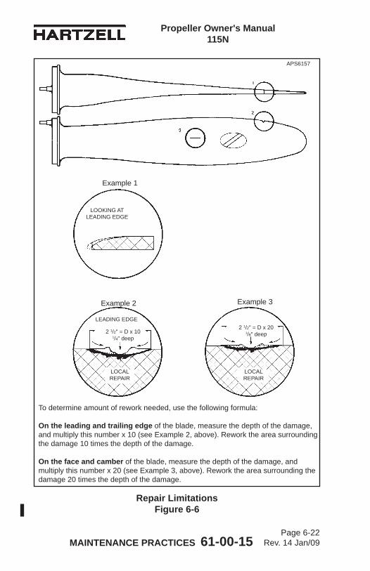
MAINTENANCE PRACTICES 61-00-15 Page 6-22
Rev. 14 Jan/09
Propeller Owner's Manual 115N
LOOKING ATLEADING EDGE
LEADING EDGE
2 1/2" = D x 101/4" deep
LOCAL REPAIR
LOCAL REPAIR
Repair Limitations Figure 6-6
To determine amount of rework needed, use the following formula:
On the leading and trailing edge of the blade, measure the depth of the damage, and multiply this number x 10 (see Example 2, above). Rework the area surrounding the damage 10 times the depth of the damage.
On the face and camber of the blade, measure the depth of the damage, and multiply this number x 20 (see Example 3, above). Rework the area surrounding the damage 20 times the depth of the damage.
Example 1
Example 2 Example 3
APS6157
2 1/2" = D x 201/8" deep
MAINTENANCE PRACTICES 61-00-15 Page 6-23
Rev. 17 Jul/12
Propeller Owner's Manual 115N
CAUTION 1: REWORK THAT INVOLVES COLD WORKING THE METAL, RESULTING IN CONCEALMENT OF A DAMAGED AREA, IS NOT PERMITTED. A STRESS CONCENTRATION MAY EXIST THAT CAN RESULT IN A BLADE FAILURE.
CAUTION 2: SHOT PEENED BLADES ARE IDENTIFIED WITH AN "S" FOLLOWING THE BLADE MODEL NUMBER, AS DESCRIBED IN THE DESCRIPTION AND OPERATION CHAPTER OF THIS MANUAL. BLADES THAT HAVE DAMAGE IN SHOT PEENED AREAS IN EXCESS OF 0.015 INCH (0.38 mm) DEEP ON THE FACE OR CAMBER OR 0.250 INCH (6.35 mm) ON THE LEADING OR TRAILING EDGES MUST BE REMOVED FROM SERVICE, AND THE REWORKED AREA SHOT PEENED BEFORE FURTHER FLIGHT. SHOT PEENING OF AN ALUMINUM BLADE MUST BE ACCOMPLISHED BY AN FAA APPROVED REPAIR FACILITY IN ACCORDANCE WITH HARTZELL PROPELLER INC. ALUMINUM BLADE OVERHAUL MANUAL 133C (61-13-33).
(1) Repairs to the leading or trailing edge are to be accomplished by removing material from the bottom of the damaged area. Remove material from this point out to both sides of the damage, providing a smooth, blended depression which maintains the original airfoil general shape.
(2) Repairs to the blade face or camber should be made inthe same manner as above. Repairs that form a continuous line across the blade section (chordwise) are unacceptable.
(3) The area of repair should be determined as follows: Leading and trailing edge damage: Depth of nick x 10. Face and camber: Depth of nick x 20. Refer to Figure 6-6.NOTE: Leading edge includes the first 10% of chord from the
leading edge. The trailing edge consists of the last 20% of chord adjacent to the trailing edge.
(4) After filing or sanding of the damaged area, the area must then be polished, first with emery cloth, Scotch Brite®, and finally with crocus cloth to remove any traces of filing.
(5) Inspect the repaired area with a 10X magnifying glass and dye penetrant. Make sure that no indication of the damage, file marks, or coarse surface finish remain.
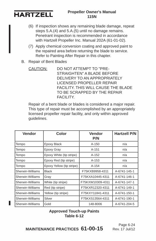
MAINTENANCE PRACTICES 61-00-15 Page 6-24
Rev. 17 Jul/12
Propeller Owner's Manual 115N
(6) If inspection shows any remaining blade damage, repeat steps 5.A.(4) and 5.A.(5) until no damage remains. Penetrant inspection is recommended in accordance with Hartzell Propeller Inc. Manual 202A (61-01-02).
(7) Apply chemical conversion coating and approved paint to the repaired area before returning the blade to service. Refer to Painting After Repair in this chapter.
B. Repair of Bent Blades
CAUTION: DO NOT ATTEMPT TO "PRE-STRAIGHTEN" A BLADE BEFORE DELIVERY TO AN APPROPRIATELY LICENSED PROPELLER REPAIR FACILITY. THIS WILL CAUSE THE BLADE TO BE SCRAPPED BY THE REPAIR FACILITY.
Repair of a bent blade or blades is considered a major repair. This type of repair must be accomplished by an appropriately licensed propeller repair facility, and only within approved guidelines.
Approved Touch-up PaintsTable 6-12
Vendor Color VendorP/N
Hartzell P/N
Tempo Epoxy Black A-150 n/a
Tempo Epoxy Gray A-151 n/a
Tempo Epoxy White (tip stripe) A-152 n/a
Tempo Epoxy Red (tip stripe) A-153 n/a
Tempo Epoxy Yellow (tip stripe) A-154 n/a
Sherwin-Williams Black F75KXB9958-4311 A-6741-145-1
Sherwin-Williams Gray F75KXA10445-4311 A-6741-146-1
Sherwin-Williams White (tip stripe) F75KXW10309-4311 A-6741-147-1
Sherwin-Williams Red (tip stripe) F75KXR12320-4311 A-6741-149-1
Sherwin-Williams Yellow (tip stripe) F75KXY11841-4311 A-6741-150-1
Sherwin-Williams Silver F75KXS13564-4311 A-6741-190-1
Sherwin-Williams Gold 148-8006 A-6741-204-5
MAINTENANCE PRACTICES 61-00-15 Page 6-25
Rev. 17 Jul/12
Propeller Owner's Manual 115N
6. Painting After Repair
CAUTION: INSTRUCTIONS AND PROCEDURES IN THIS SECTION MAY INVOLVE PROPELLER CRITICAL PARTS. REFER TO THE INTRODUCTION CHAPTER OF THIS MANUAL FOR INFORMATION ABOUT PROPELLER CRITICAL PARTS. REFER TO THE ILLUSTRATED PARTS LIST CHAPTER OF THE APPLICABLE OVERHAUL MANUAL(S) FOR THE IDENTIFICATION OF SPECIFIC PROPELLER CRITICAL PARTS.
A. General(1) Propeller blades are painted with a durable specialized
coating that is resistant to abrasion. If this coating becomes eroded, it is necessary to repaint the blades to provide proper corrosion and erosion protection. Painting should be performed by an appropriately licensed propeller repair facility in accordance with Hartzell Propeller Inc. Manual 202A (61-01-02).
(2) It is permitted to perform a blade touch-up with aerosol paint in accordance with the procedures in Painting of Aluminum Blades that follows.
(3) Refer to Table 6-12 for paints that are approved for blade touch-up.
(4) The paint manufacturers may be contacted by using the following information:
Tempo Products Co. Sherwin Williams Co.A plasti-kote Company 2390 Arbor Boulevard 1000 Lake Road Dayton, Ohio Medina, OH 44256 Tel: 937.298.8691 Tel: 800.321.6300 Fax: 937.298.3820 Fax: 216.349.4241 Cage Code: 0W199 Cage Code: 07708
MAINTENANCE PRACTICES 61-00-15 Page 6-26
Rev. 17 Jul/12
Propeller Owner's Manual 115N
B. Painting of Aluminum Blades
WARNING: CLEANING AGENTS (ACETONE, #700 LACQUER THINNER, AND MEK), ARE FLAMMABLE AND TOXIC TO THE SKIN, EYES, AND RESPIRATORY TRACT. SKIN AND EYE PROTECTION ARE REQUIRED. AVOID PROLONGED CONTACT. USE IN WELL VENTILATED AREA.
CAUTION: ANY REFINISHING PROCEDURE CAN ALTER PROPELLER BALANCE. PROPELLERS THAT ARE OUT OF BALANCE MAY EXPERIENCE EXCESSIVE VIBRATIONS WHILE IN OPERATION.
(1) Using a clean cloth moistened with acetone, #700 lacquer thinner, or MEK, wipe the surface of the blade to remove any contaminants and permit the solvent to evaporate.
(2) Using 120 to 180 grit sandpaper, sand to feather the existing coatings away from the eroded or repaired area.(a) Paint erosion is typically very similar on all blades
in a propeller assembly. If one blade has more extensive paint erosion, e.g., in the tip area, sand all the blades in the tip area to replicate the repair of the most severely damaged blade tip. This practice is essential in maintaining balance after refinishing.
(3) Using acetone, #700 lacquer thinner, or MEK, wipe the surface of the blade and permit the solvent to evaporate.
MAINTENANCE PRACTICES 61-00-15 Page 6-27
Rev. 14 Jan/09
Propeller Owner's Manual 115N
(4) Before refinishing the blades, apply a corrosion preventive coating to the bare aluminum surface. (a) Tasdip AL 100, Chromicote L-25, or Alodine 1201 and
1200S are approved chemical conversion coatings. (b) Apply these coatings in accordance with the
directions provided by the product manufacturer.(5) Apply masking material for the anti-icing or de-ice boot
and tip stripes, as needed.
WARNING: FINISH COATINGS ARE FLAMMABLE AND TOXIC TO THE SKIN, EYES AND RESPIRATORY TRACT. SKIN AND EYE PROTECTION ARE REQUIRED. AVOID PROLONGED CONTACT. USE IN A WELL VENTILATED AREA.
CAUTION: APPLY FINISH COATING ONLY TO THE DEGREE REQUIRED TO UNIFORMLY COVER THE REPAIR/EROSION. AVOID EXCESSIVE PAINT BUILD-UP ALONG THE TRAILING EDGE TO AVOID CHANGING THE BLADE PROFILE.
(6) Apply a sufficient amount of finish coating to achieve 2 to 4 mil thickness when dry. (a) Re-coat before 30 minutes, or after 48 hours. (b) If the paint is permitted to dry longer than four (4)
hours, it must be lightly sanded before another coat is applied.
(7) Remove the masking material from the tip stripes and re-mask to permit the tip stripe refinishing, if required.
(8) Apply sufficient tip stripe coating to achieve 2 to 4 mil thickness when dry. (a) Re-coat before 30 minutes, or after 48 hours. (b) If the paint is permitted to dry longer than four (4)
hours, it must be lightly sanded before another coat is applied.
(9) Remove the masking immediately from the anti-icing or de-ice boot and tip stripes, if required.
MAINTENANCE PRACTICES 61-00-15 Page 6-28
Rev. 14 Jan/09
Propeller Owner's Manual 115N
(10) Optionally, perform dynamic balancing in accordance with the procedures and limitations specified in the Dynamic Balance section of this chapter.
MAINTENANCE PRACTICES 61-00-15 Page 6-29
Rev. 17 Jul/12
Propeller Owner's Manual 115N
7. Dynamic BalanceA. Overview
CAUTION 1: INSTRUCTIONS AND PROCEDURES IN THIS SECTION MAY INVOLVE PROPELLER CRITICAL PARTS. REFER TO THE INTRODUCTION CHAPTER OF THIS MANUAL FOR INFORMATION ABOUT PROPELLER CRITICAL PARTS. REFER TO THE ILLUSTRATED PARTS LIST CHAPTER OF THE APPLICABLE OVERHAUL MANUAL(S) FOR THE IDENTIFICATION OF SPECIFIC PROPELLER CRITICAL PARTS.
CAUTION 2: IF REFLECTIVE TAPE IS USED FOR DYNAMIC BALANCING, DO NOT APPLY THE TAPE ON EXPOSED BARE METAL OF THE BLADE. THIS WILL ALLOW MOISTURE TO COLLECT UNDER THE TAPE AND CAUSE CORROSION THAT CAN PERMANENTLY DAMAGE THE BLADE. REFLECTIVE TAPE MUST BE REMOVED AFTER DYNAMIC BALANCING IS COMPLETED.
NOTE: Dynamic balance is recommended to reduce vibrations that may be caused by a rotating system (propeller and engine) imbalance. Dynamic balancing can help prolong the life of the propeller, engine, airframe, and avionics.
(1) Dynamic balance is accomplished by using an accurate means of measuring the amount and location of the dynamic imbalance.
(2) The number of balance weights installed must not exceed the limits specified in this chapter.
(3) Follow the dynamic balance equipment manufacturer’s instructions for dynamic balance in addition to the specifications of this section.NOTE: Some engine manufacturers' instructions also
contain information on dynamic balance limits.
MAINTENANCE PRACTICES 61-00-15 Page 6-30
Rev. 14 Jan/09
Propeller Owner's Manual 115N
B. Inspection Procedures Before Balancing(1) Visually inspect the propeller assembly before dynamic
balancing.NOTE: The first run-up of a new or overhauled
propeller assembly may leave a small amount of grease on the blades and inner surface of the spinner dome.
(a) Use Stoddard solvent (or equivalent) to completely remove any grease on the blades or inner surface of the spinner dome.
(b) Visually examine each propeller blade assembly for evidence of grease leakage.
(c) Visually examine the inner surface of the spinner dome for evidence of grease leakage.
(2) If there is no evidence of grease leakage, lubricate the propeller in accordance with the Maintenance Practices chapter in this manual. If grease leakage is evident, determine the location of the leak and correct before re-lubricating the propeller and dynamic balancing.
(3) Before dynamic balance, record the number and location of all balance weights.
(4) Static balance is accomplished at a propeller overhaul facility when an overhaul or major repair is performed. NOTE: If static balancing is not accomplished
before dynamic balancing, the propeller may be so severely unbalanced that dynamic balance may be unachievable because of measurement equipment limitations.
MAINTENANCE PRACTICES 61-00-15 Page 6-31
Rev. 14 Jan/09
Propeller Owner's Manual 115N
C. Modifying Spinner Bulkhead to Accommodate Dynamic Balance Weights
CAUTION: ALL HOLE/BALANCE WEIGHT LOCATIONS MUST TAKE INTO CONSIDERATION, AND MUST AVOID, ANY POSSIBILITY OF INTERFERING WITH THE ADJACENT AIRFRAME, PROPELLER ICE PROTECTION SYSTEM, AND ENGINE COMPONENTS.
(1) It is recommended that balance weights be placed in a radial location on aluminum spinner bulkheads that have not been previously drilled.
(2) The radial location should be outboard of the de-ice slip ring or bulkhead doubler and inboard of the bend where the bulkhead creates the flange surface to attach the spinner dome.
(3) Twelve equally spaced locations are recommended for weight attachment.
(4) Installing nut plates (10-32 thread) of the type used to attach the spinner dome will permit convenient balance weight attachment on the engine side of the bulkhead.
(5) Alternatively, drilling holes for use with the AN3-( ) type bolts with self-locking nuts is permitted.
(6) Chadwick-Helmuth Manual AW-9511-2, “The Smooth Propeller”, specifies several generic bulkhead rework procedures. These are permitted if they comply with the conditions specified herein.
MAINTENANCE PRACTICES 61-00-15 Page 6-32
Rev. 17 Jul/12
Propeller Owner's Manual 115N
D. Placement of Balance Weights for Dynamic Balance(1) The preferred method of attachment of dynamic balance
weights is to add the weights to the spinner bulkhead.NOTE: Many spinner bulkheads have factory installed
self-locking nut plates provided for this purpose.(2) If the location of static balance weights has not been
altered, subsequent removal of the dynamic balance weights will return the propeller to its original static balance condition.
(3) Use only stainless or plated steel washers as dynamic balance weights on the spinner bulkhead.
(4) Do not exceed a maximum weight per location of 0.9 oz. (25.5 g). NOTE: This is approximately equal to six AN970 style
washers (0.188 inch ID, 0.875 inch OD, 0.063 inch thickness) (4.78 mm ID, 22.23 mm OD, 1.60 mm thickness).
(5) Install weights using aircraft quality #10-32 or AN-3( ) type screws or bolts.
(6) Balance weight screws attached to the spinner bulkhead must protrude through the self-locking nuts or nut plates a minimum of one thread and a maximum of four threads.
CAUTION: IF REFLECTIVE TAPE IS USED FOR DYNAMIC BALANCING, REMOVE THE TAPE IMMEDIATELY UPON COMPLETION. TAPE THAT REMAINS ON THE BLADE WILL PERMIT MOISTURE TO COLLECT UNDER THE TAPE AND CAUSE CORROSION THAT CAN PERMANENTLY DAMAGE THE BLADE.
(7) Unless otherwise specified by the engine or airframe manufacturer, Hartzell Propeller Inc. recommends that the propeller be dynamically balanced to a reading of 0.2 IPS, or less.
(8) If reflective tape is used for dynamic balancing, remove the tape immediately after balancing is completed.
(9) Make a record in the propeller logbook of the number and location of dynamic balance weights, and static balance weights if they have been reconfigured.
MAINTENANCE PRACTICES 61-00-15 Page 6-33
Rev. 17 Jul/12
Propeller Owner's Manual 115N
8. Propeller Low Pitch Setting
WARNING 1: RPM ADJUSTMENTS MUST BE MADE WITH REFERENCE TO A CALIBRATED TACHOMETER. AIRCRAFT MECHANICAL TACHOMETERS DEVELOP ERRORS OVER TIME, AND SHOULD BE PERIODICALLY RECALIBRATED TO MAKE SURE THE PROPER RPM IS DISPLAYED.
WARNING 2: LOW PITCH BLADE ANGLE ADJUSTMENTS MUST BE MADE IN CONSULTATION WITH THE APPLICABLE TYPE CERTIFICATE OR SUPPLEMENTAL TYPE CERTIFICATE HOLDERS MAINTENANCE DATA.
CAUTION: INSTRUCTIONS AND PROCEDURES IN THIS SECTION MAY INVOLVE PROPELLER CRITICAL PARTS. REFER TO THE INTRODUCTION CHAPTER OF THIS MANUAL FOR INFORMATION ABOUT PROPELLER CRITICAL PARTS. REFER TO THE ILLUSTRATED PARTS LIST CHAPTER OF THE APPLICABLE OVERHAUL MANUAL(S) FOR THE IDENTIFICATION OF SPECIFIC PROPELLER CRITICAL PARTS.
A. Low Pitch Stop - All Propeller Models(1) The propeller low pitch stop is set at the factory to the
aircraft TC or STC Holder's requirements and should not require any additional adjustment. The TC or STC Holder provides the required low pitch stop blade angle and may also provide the acceptable RPM range for a maximum power static condition. Be aware that the aircraft TC or STC holder may specify the static RPM to be less than the RPM to which the engine is rated.
(2) An overspeed at the maximum power static condition may indicate that the propeller low-pitch blade angle is set too low or that the governor is improperly adjusted.
(3) An underspeed during the maximum power static condition may be caused by any one or a combination of the following: The propeller low pitch blade angle is too high; the governor is improperly adjusted; the engine is not producing rated power.
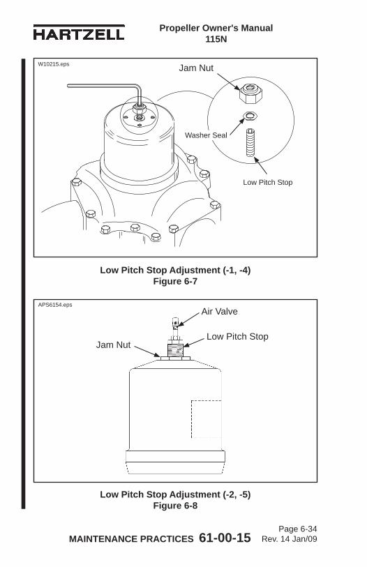
MAINTENANCE PRACTICES 61-00-15 Page 6-34
Rev. 14 Jan/09
Propeller Owner's Manual 115N
Low Pitch Stop Adjustment (-1, -4) Figure 6-7
Low Pitch Stop Adjustment (-2, -5) Figure 6-8
Low Pitch StopJam Nut
Air Valve
Washer Seal
Jam Nut
Low Pitch Stop
APS6154.eps
W10215.eps
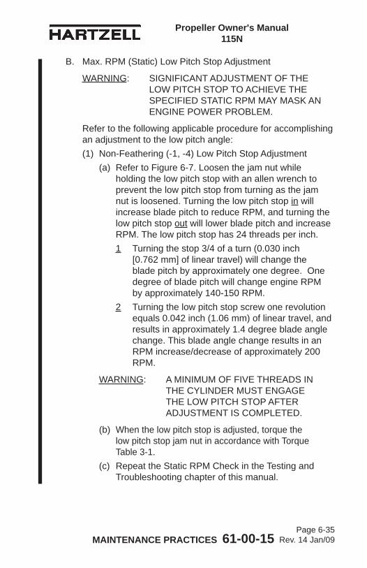
MAINTENANCE PRACTICES 61-00-15 Page 6-35
Rev. 14 Jan/09
Propeller Owner's Manual 115N
B. Max. RPM (Static) Low Pitch Stop Adjustment
WARNING: SIGNIFICANT ADJUSTMENT OF THE LOW PITCH STOP TO ACHIEVE THE SPECIFIED STATIC RPM MAY MASK AN ENGINE POWER PROBLEM.
Refer to the following applicable procedure for accomplishing an adjustment to the low pitch angle:(1) Non-Feathering (-1, -4) Low Pitch Stop Adjustment
(a) Refer to Figure 6-7. Loosen the jam nut while holding the low pitch stop with an allen wrench to prevent the low pitch stop from turning as the jam nut is loosened. Turning the low pitch stop in will increase blade pitch to reduce RPM, and turning the low pitch stop out will lower blade pitch and increase RPM. The low pitch stop has 24 threads per inch.1 Turning the stop 3/4 of a turn (0.030 inch
[0.762 mm] of linear travel) will change the blade pitch by approximately one degree. One degree of blade pitch will change engine RPM by approximately 140-150 RPM.
2 Turning the low pitch stop screw one revolution equals 0.042 inch (1.06 mm) of linear travel, and results in approximately 1.4 degree blade angle change. This blade angle change results in an RPM increase/decrease of approximately 200 RPM.
WARNING: A MINIMUM OF FIVE THREADS IN THE CYLINDER MUST ENGAGE THE LOW PITCH STOP AFTER ADJUSTMENT IS COMPLETED.
(b) When the low pitch stop is adjusted, torque the low pitch stop jam nut in accordance with Torque Table 3-1.
(c) Repeat the Static RPM Check in the Testing and Troubleshooting chapter of this manual.
MAINTENANCE PRACTICES 61-00-15 Page 6-36
Rev. 14 Jan/09
Propeller Owner's Manual 115N
(2) Feathering (-2, -5) Low Pitch Stop Adjustment
WARNING: AIR PRESSURE (-2, -5 PROPELLERS) MUST BE REDUCED TO 0 PSI BEFORE ANY LOW PITCH ADJUSTMENT MAY BE MADE.
(a) Refer to Figure 6-8. Loosen the jam nut while holding the low pitch stop with a second wrench to prevent the low pitch stop from turning as the jam nut is loosened. Turning the low pitch stop into the cylinder will increase blade pitch and reduce RPM, and turning the low pitch stop out of the cylinder will lower blade pitch and increase RPM. The low pitch stop has 20 threads per inch.1 Turning the low pitch stop 2/3 of a turn
(0.030 inch [0.762 mm] of linear travel) will change the blade pitch by approximately one degree. This blade angle change results in an RPM increase/decrease of approximately 140-150 RPM.
2 Turning the low pitch stop screw one full turn (0.050 inch [1.27 mm] of linear travel) will change the blade pitch approximately 1.7 degree. This blade angle change results in an RPM increase/decrease of approximately 250 RPM.
WARNING: A MINIMUM OF FIVE THREADS IN THE CYLINDER MUST ENGAGE THE LOW PITCH STOP AFTER ADJUSTMENT IS COMPLETED.
(b) When the low pitch stop is adjusted, torque the low pitch stop jam nut in accordance with Torque Table 3-1.
(c) Repeat the Static RPM Check in the Testing and Troubleshooting Chapter of this manual.
MAINTENANCE PRACTICES 61-00-15 Page 6-37
Rev. 17 Jul/12
Propeller Owner's Manual 115N
9. Propeller High Pitch SettingsA. High Pitch (Min. RPM) Stop or Feathering Pitch Stop
(1) The high pitch and feathering pitch stop are set at the factory per the aircraft manufacturer's recommendations. These stops are adjustable only by an appropriately licensed propeller repair facility or the Hartzell Propeller Inc. factory.
10. Start Lock SettingsA. Start Lock Pitch Stop
(1) The start lock pitch stops are set at the factory per the aircraft manufacturer's recommendations. These stops are adjustable only by an appropriately licensed propeller repair facility or the Hartzell Propeller Inc. factory.
11. Propeller Ice Protection SystemsA. Electric De-ice System
(1) Consult the Pilot Operating Handbook (including all supplements) regarding flight into conditions of known icing. The aircraft may not be certificated for flight in known icing conditions, even though propeller de-ice equipment is installed.
(2) Refer to the Anti-ice and De-ice Systems chapter of this manual for functional tests of the de-ice system.
B. Anti-ice System(1) Consult the Pilot Operating Handbook (including all
supplements) regarding flight into conditions of known icing. The aircraft may not be certificated for flight in known icing conditions, even though propeller anti-ice equipment is installed.
(2) Refer to the Anti-ice and De-ice Systems chapter of this manual for functional tests of the anti-ice system.
MAINTENANCE PRACTICES 61-00-15 Page 6-38
Rev. 17 Jul/12
Propeller Owner's Manual 115N
(This page is intentionally blank.)
ANTI-ICE AND DE-ICE SYSTEMS 61-00-15 Page 7-1
Rev. 14 Jan/09
Propeller Owner's Manual 115N
ANTI-ICE AND DE-ICE SYSTEM - CONTENTS
1. Introduction ................................................................................ 7-3A. Propeller De-ice System .................................................... 7-3B. Propeller Anti-ice System .................................................. 7-3
2. System Description .................................................................... 7-4A. De-ice System ................................................................... 7-4B. Anti-ice System .................................................................. 7-5
3. De-ice System Functional Tests ................................................. 7-6
4. Anti-ice System Functional Tests ............................................... 7-6
5. De-ice and Anti-ice System Inspections ..................................... 7-7A. De-ice System Inspections ................................................ 7-7B. Anti-ice System Inspections .............................................. 7-7
6. De-ice and Anti-ice System Troubleshooting ............................. 7-8A. De-ice System Troubleshooting ......................................... 7-8B. Anti-ice System Troubleshooting ....................................... 7-8
ANTI-ICE AND DE-ICE SYSTEMS 61-00-15 Page 7-2
Rev. 14 Jan/09
Propeller Owner's Manual 115N
(This page is intentionally blank.)
ANTI-ICE AND DE-ICE SYSTEMS 61-00-15 Page 7-3
Rev. 14 Jan/09
Propeller Owner's Manual 115N
1. IntroductionA. Propeller De-ice System
(1) A propeller de-ice system is a system that removes ice after it forms on the propeller blades. A de-ice system uses electrical heating elements to melt the ice layer next to the blades, permitting the ice to be thrown from the blade by centrifugal force. Blades are alternately heated and permitted to cool as the current is applied and removed automatically by the de-ice system timer.
(2) System components include a timer or cycling unit, electrical slip ring(s), brush block assembly, and blade mounted de-ice boots.
B. Propeller Anti-ice System(1) A propeller anti-ice system is a system that prevents
formation of ice on propeller surfaces. An anti-ice system dispenses a fluid that mixes with, and reduces the freezing point of, moisture on the propeller blades. The mixture may then flow off the blades before it forms ice.
(2) System components include a fluid tank, pump, slinger ring, and blade mounted fluid anti-icing boots.
ANTI-ICE AND DE-ICE SYSTEMS 61-00-15 Page 7-4
Rev. 13 Aug/06
Propeller Owner's Manual 115N
2. System DescriptionA. De-ice System
NOTE: Because of the wide variances of various de-ice systems, the following description is general in nature. Consult the airframe manufacturer’s manual for a description of your specific de-ice system and controls.
The de-ice system is controlled by the pilot via a cockpit control switch. This switch applies electrical power to the de-ice system, which will operate as long as the switch is in the ON position. Depending upon the system, another set of cockpit controls may be available. One of these controls is a mode selector, which permits the pilot to select two cycling speeds, for heavy or light icing conditions. Some systems on twin engine aircraft have a switch which provides a full de-ice mode, which permits the pilot to de-ice both propellers simultaneously. This switch may only be used for short periods and is used when ice builds up on the propeller before the system is turned on.An ammeter, which indicates current drawn by the system, is normally located near the de-ice system switches. This meter may indicate total system load, or a separate meter may be supplied for each propeller.A timer, which is turned off and on by the cockpit control, is used to sequence the de-ice system. This timer turns the de-ice system on and off in proper sequence, controlling the heating interval to each propeller for even de-icing. A brush block, which is mounted on the engine immediately behind the propeller, supplies electrical current to the de-ice boot on each propeller blade via a slip ring. The slip ring is normally mounted on the spinner bulkhead.When the pilot places the de-ice system cockpit control switch in the ON position, the system timer begins to operate. As the timer sequences, power is delivered to a power relay. The power relay delivers high current to the brush block and slip ring. Each propeller is de-iced in turn by the timer.
ANTI-ICE AND DE-ICE SYSTEMS 61-00-15 Page 7-5
Rev. 14 Jan/09
Propeller Owner's Manual 115N
B. Anti-ice System(1) The anti-ice system is controlled by the pilot via a
cockpit mounted rheostat. This rheostat operates a pump that pumps anti-ice fluid from the tank at a controlled rate.
(2) The anti-ice fluid is delivered through a filter, a check valve, and then through tubing to a slinger ring located at the rear of the spinner bulkhead. The anti-ice fluid is dispensed into the rotating slinger ring, which holds the fluid in a curved channel by centrifugal force. The fluid then flows out of the slinger ring through feed tubes which are welded to the slinger ring, and then out onto the blade anti-icing boots.
(3) The blade anti-icing boots are ridged rubber sheets that are glued to the leading edge of the blades. The ridges in the anti-icing boots direct the fluid out onto the blades and permit for an even distribution of the anti-ice fluid across the blades.
ANTI-ICE AND DE-ICE SYSTEMS 61-00-15 Page 7-6
Rev. 14 Jan/09
Propeller Owner's Manual 115N
3. De-ice System Functional TestsA. Functional tests of the de-ice system should be performed
in accordance with the following Hartzell Manuals, which are available on the Hartzell Propeller website at www.hartzellprop.com:
(1) Hartzell Manual 181 (30-60-81) - Propeller Ice Protection System Component Maintenance Manual
(2) Hartzell Manual 182 (61-12-82) - Propeller Electrical De-ice Boot Removal and Installation Manual
4. Anti-ice System Functional TestsA. Operational Checks of the anti-ice system should be
performed in accordance with the following Hartzell Manuals, which are available on the Hartzell Propeller website at www.hartzellprop.com:
(1) Hartzell Manual 181 (30-60-81) - Propeller Ice Protection System Component Maintenance Manual
(2) Hartzell Manual 183 (61-12-83) - Propeller Anti-icing Boot Removal and Installation Manual

ANTI-ICE AND DE-ICE SYSTEMS 61-00-15 Page 7-7
Rev. 14 Jan/09
Propeller Owner's Manual 115N
5. De-ice and Anti-ice System InspectionsThe inspections detailed below are made on a regular basis, either before flight, during the 100 hour inspection, or if a problem is noted. Possible corrections to problems discovered during inspections, additional inspections, and limits are detailed in the following Hartzell manuals.A. De-ice System Inspections
(1) Perform inspections in accordance with the following Hartzell Manuals, which are available on the Hartzell Propeller website at www.hartzellprop.com:
(a) Hartzell Manual 181 (30-60-81) - Propeller Ice Protection System Component Maintenance Manual
(b) Hartzell Manual 182 (61-12-82) - Propeller Electrical De-ice Boot Removal and Installation Manual
B. Anti-ice System Inspections(1) Perform inspections in accordance with the following
Hartzell Manuals, which are available on the Hartzell Propeller website at www.hartzellprop.com:
(a) Hartzell Manual 181 (30-60-81) - Propeller Ice Protection System Component Maintenance Manual
(b) Hartzell Manual 183 (61-12-83) - Propeller Anti-icing Boot Removal and Installation Manual
ANTI-ICE AND DE-ICE SYSTEMS 61-00-15 Page 7-8
Rev. 14 Jan/09
Propeller Owner's Manual 115N
6. De-ice and Anti-ice System TroubleshootingA. De-ice System Troubleshooting
(1) Perform troubleshooting in accordance with the following Hartzell Manuals, which are available on the Hartzell Propeller website at www.hartzellprop.com:
(a) Hartzell Manual No. 181 (30-60-81) - Propeller Ice Protection System Component Maintenance Manual
(b) Hartzell Manual No. 182 (61-12-82) - Propeller Electrical De-ice Boot Removal and Installation Manual
B. Anti-ice System Troubleshooting(1) Perform troubleshooting in accordance with the following
Hartzell Manuals, which are available on the Hartzell Propeller website at www.hartzellprop.com:
(a) Hartzell Manual No. 181 (30-60-81) - Propeller Ice Protection System Component Maintenance Manual
(b) Hartzell Manual No. 183 (61-12-83) - Propeller Anti-icing Boot Removal and Installation Manual
RECORDS 61-00-15 Page 8-1
Rev. 14 Jan/09
Propeller Owner’s Manual 115N
RECORDS - CONTENTS
1. Introduction ................................................................................8-3
2. Record Keeping .........................................................................8-3A. Information to be Recorded ...................................................8-3
RECORDS 61-00-15 Page 8-2
Rev. 14 Jan/09
Propeller Owner’s Manual 115N
(This page is intentionally blank.)
RECORDS 61-00-15 Page 8-3
Rev. 14 Jan/09
Propeller Owner’s Manual 115N
1. IntroductionFederal Aviation Regulations require that a record be kept of any repairs, adjustments, maintenance, or required inspections performed on a propeller or propeller system.This chapter provides a method for maintaining these records. It also provides a location for recording information that can aid the service technician in maintaining the propeller system.
2. Record KeepingA. Information to be Recorded
(1) Information which is required to be recorded is listed in Part 43 of the U.S. Federal Aviation Regulations.
(2) The log book may also be used to record:(a) Propeller postion (on aircraft)(b) Propeller model.(c) Propeller serial number(d) Blade design number(e) Blade serial numbers(f) Spinner assembly part number(g) Propeller pitch range(h) Aircraft information (aircraft type, model, serial
number and registration number)

RECORDS 61-00-15 Page 8-4
Rev. 14 Jan/09
Propeller Owner’s Manual 115N
(This page is intentionally blank.)