project helios group 10 michael gannon michael peffers muhammed ali khan ahmad buleybel
TRANSCRIPT

Project Helios
Group 10
Michael GannonMichael Peffers
Muhammed Ali KhanAhmad Buleybel

Sponsored By
• Dave Norvell of Energy and sustainability
Also Working with Mechanical Engineers: Industrial Engineers:
Daniel Gould Amanda LongmanConnie Griesemer Joshua MacNaughton Ryan Lewis Andrew WolodkiewiczJonathan Torres Ryan Tribbey

Project Overview
• Design a panel by panel monitoring system– Monitoring system must be self sustaining– Wirelessly transmit data– Data will be collected every 5 minutes for duration
of the day• Publish real time information online – Data must be graphed for easy interpretation– Publically accessible
• UCF going 15% carbon free by 2020

Goals & Objectives
• Monitor each panel for:– Voltage– Temp– Current
• Display data online in real time• Transmit data from field to web server
wirelessly• System will sustain its own energy

Specifications
• Voltage reading accuracy within 100mV• Current reading accuracy within 100mA• Temp reading accuracy within .1 oC• Wireless range of at least 250 meters• Web data will be uploaded every 5 minutes• Total current consumed below 1.5A

Block Diagram

Solar Panels and Components SelectionAhmad Buleybel

Solar Panel
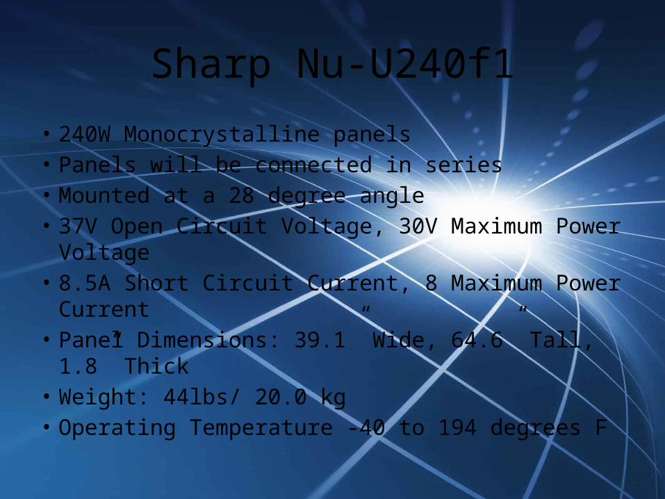
Sharp Nu-U240f1
• 240W Monocrystalline panels• Panels will be connected in series• Mounted at a 28 degree angle• 37V Open Circuit Voltage, 30V Maximum Power
Voltage• 8.5A Short Circuit Current, 8 Maximum Power Current• Panel Dimensions: 39.1” Wide, 64.6” Tall, 1.8” Thick• Weight: 44lbs/ 20.0 kg• Operating Temperature -40 to 194 degrees F
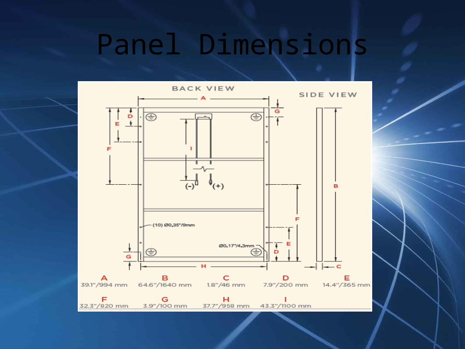
Panel Dimensions

12 Panels
The panels will be connected in series • 3124 W• 361 V• 8.5 A

Array
• Combiner Box • Surge Protector• Fuse and Fuse Holder• MC4 Connectors
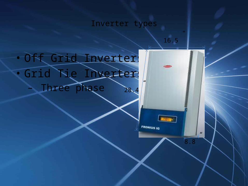
Inverter types
• Off Grid Inverters• Grid Tie Inverters– Three phase
16.5”
28.4”
8.8”
Choice of inverter
• Fronius IG 4000 Inverter• Recommended PV power 3000-5000 W• Max. DC Input Voltage 500V, Operating DC
Voltage 150-450V• Max. usable DC input current 26.1A• Weight: 42lbs/ 19kgs• Operating Temperature: -5 to 122 degrees F

MC4
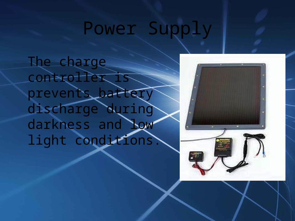
Power Supply
The charge controller is prevents battery discharge during darkness and low light conditions.

Batteries Options
The Batteries that were chosen were Power Sonic 12V/21 AH batteries

Monitoring System DesignMichael Peffers & Michael Gannon
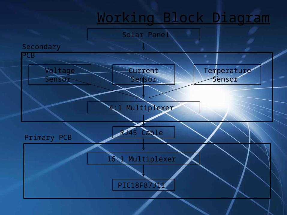
Working Block Diagram Solar Panel
Current SensorVoltage Sensor Temperature Sensor
4:1 Multiplexer
RJ45 Cable
16:1 Multiplexer
PIC18F87J11
Secondary PCB
Primary PCB

Secondary PCB
• Will connected in parallel with Solar panel System
• Board will consist of three separate sensors
• Voltage, Current, and Temperature
• All sensors are hardware designed to an accuracy at least ± 1.5%
Figure 2: Dimension (obtained from datasheet)
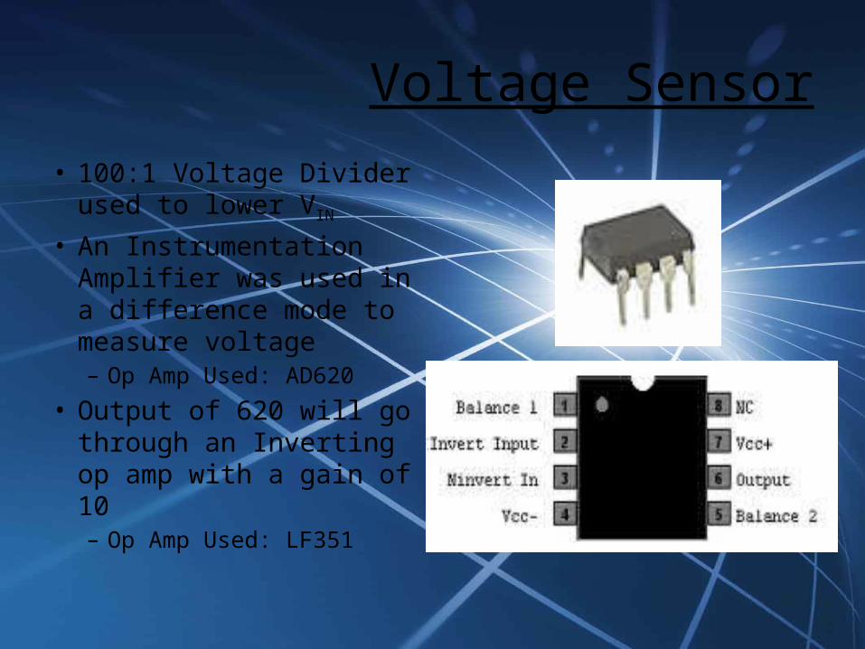
Voltage Sensor
• 100:1 Voltage Divider used to lower VIN
• An Instrumentation Amplifier was used in a difference mode to measure voltage– Op Amp Used: AD620
• Output of 620 will go through an Inverting op amp with a gain of 10– Op Amp Used: LF351
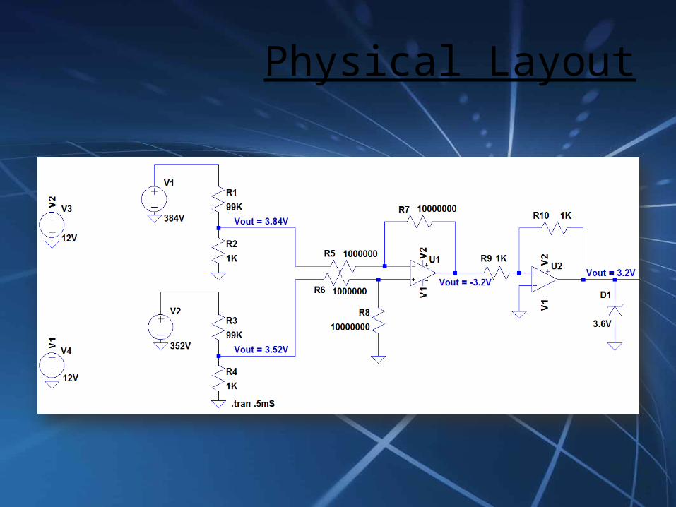
Physical Layout
Current Sensor
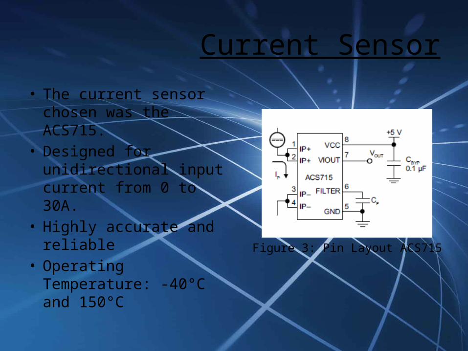
• The current sensor chosen was the ACS715.
• Designed for unidirectional input current from 0 to 30A.
• Highly accurate and reliable
• Operating Temperature: -40°C and 150°C
Figure 3: Pin Layout ACS715
Current Sensor
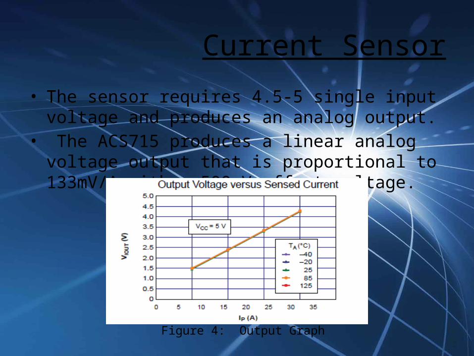
• The sensor requires 4.5-5 single input voltage and produces an analog output.
• The ACS715 produces a linear analog voltage output that is proportional to 133mV/A with a 500mV offset voltage.
Figure 4: Output Graph

Physical Layout
Figure 5: ACS715 Breakout Board

Temperature Sensor
• Temperature sensor chosen: LM34 Precision Fahrenheit Sensor.
• Typical Accuracy of ±1½°F
• Temperature reading range from -50 to +300°F
• The LM34 has a low output impedance and precise calibration which make it easy to work with.
• It outputs an analog voltage that is linearly proportional to the a Fahrenheit temperature +10mV/°F

Temperature Sensor
• Dimensions: • 20 Gauge wire leads will be hand soldered to the leads of the sensor to provide the power and ground and to also retrieve the output.
• These leads will be brought directly to the secondary printed circuit board from the sensor.Figure 6: LM34 Dimensions
Temperature Sensor
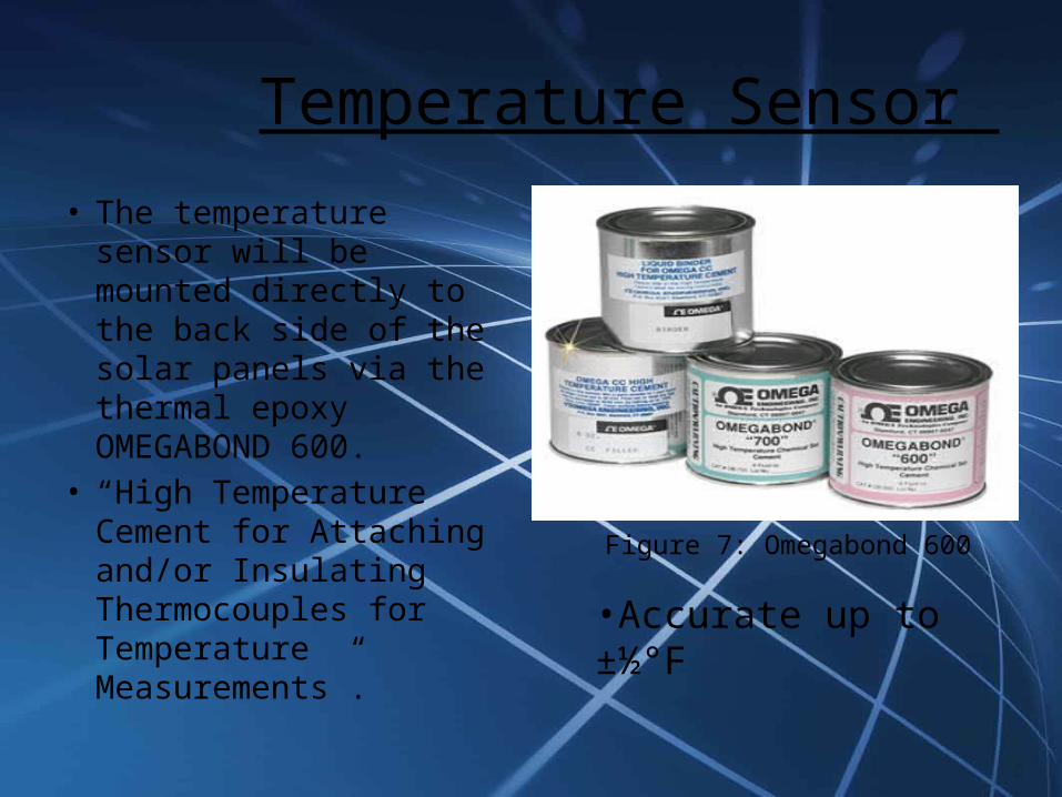
• The temperature sensor will be mounted directly to the back side of the solar panels via the thermal epoxy OMEGABOND 600.
• “High Temperature Cement for Attaching and/or Insulating Thermocouples for Temperature Measurements”.
Figure 7: Omegabond 600
•Accurate up to ±½°F

Physical Layout

4:1 Multiplexer• The multiplexer that was
chosen for this project was the ADG409 by Analog Devices.
• This part is a analog multiplexer with four differential channels.
• The ADG409 switches one of four differential inputs to a common differential output as determined by the 2-bit binary address lines A0 and A1.
• An EN input on the device is used to enable or disable the device. When disabled, all channels are switched off.
Figure 8: ADG409 - 4:1 Multiplexer

4:1 Multiplexer Physical Layout

Secondary PCB Physical Circuit Layout
Temperature SensorCurrent Sensor
Differential Amplifier Circuit to Measure Voltage Between Panels

RJ45 – Cat5e Cable
• We chose to use twisted pair RJ45 Cat5e cable because of it’s ability to cancel noise on the lines and it’s ease of implementation.
• RJ45 Connection:Pin 1 – VCC DataPin 2 – GroundPins 3-5 Address Select Lines for Mux
Figure 8: RJ45 Male Connector
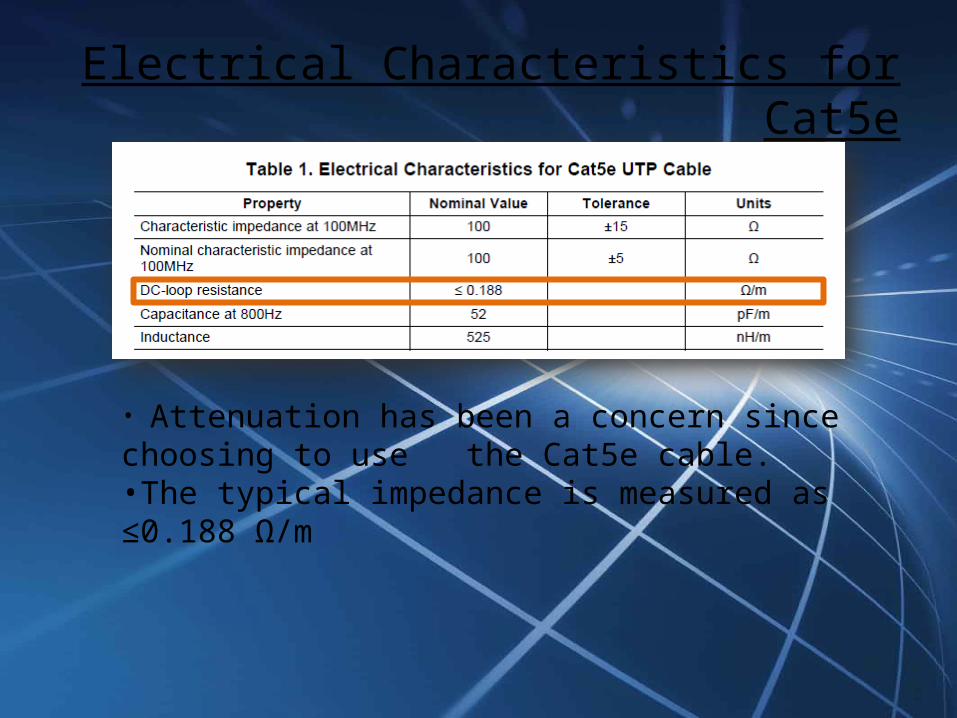
Electrical Characteristics for Cat5e
• Attenuation has been a concern since choosing to use the Cat5e cable.•The typical impedance is measured as ≤0.188 Ω/m
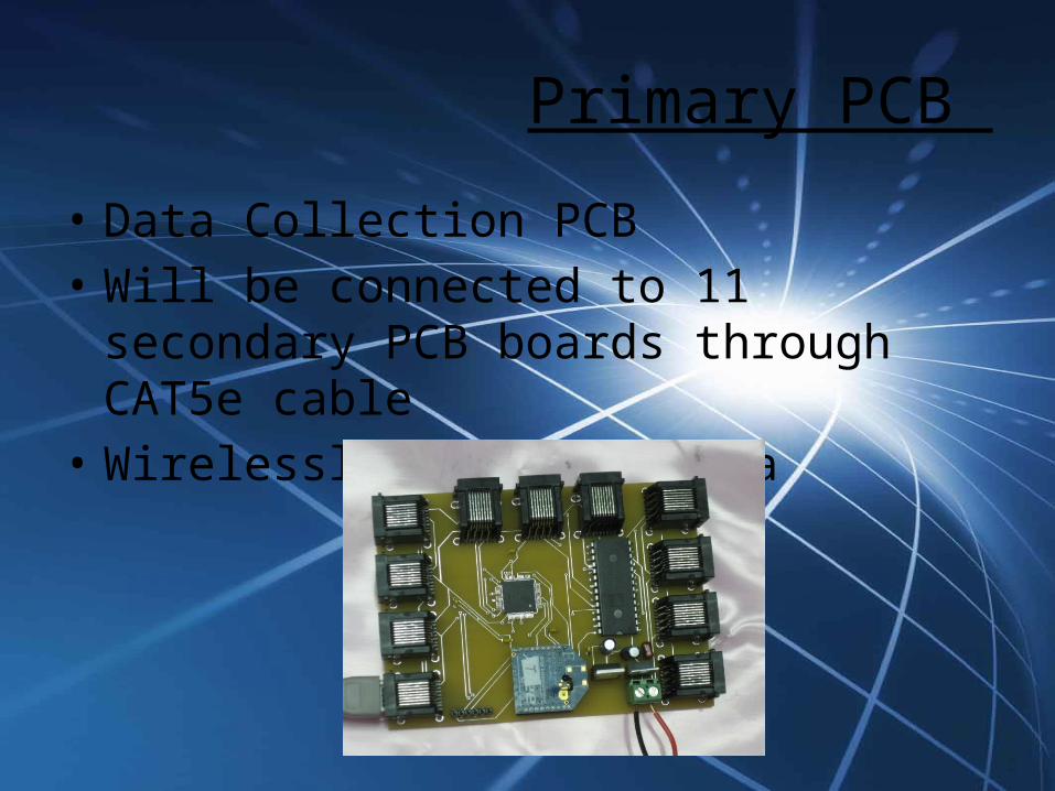
Primary PCB
• Data Collection PCB• Will be connected to 11 secondary PCB boards
through CAT5e cable• Wirelessly transmit data

16:1 Multiplexer • The 16:1 multiplexer chosen: ADG406BNZ
• Single supply operation
• Wide range of supply voltage of +5V - +12V
•Allows us to only you 1 A/D pin on PIC18F

PIC18F87J11
• 80 Pin Device with 68 I/O pins• Programmable in C• 15 10-bit Input A/D channels• 128 Kbit RAM• Sleep mode uses nano watts• Very fast wake up time

Explorer Board
•Low cost demo board used for evaluating our PIC18F87J11 processor•Uses the PICkit 3 programmer debugger •Program to go •Multiple serial interface (USB, RJ11, RS232)•Emulator is MPlab

PICKIT 3

Primary PCB Physical Circuit Layout
X-Bee
Pic18F87J11
16:1 Multiplexer

Wireless CommunicationMuhammed Khan

Wireless Communication Options
We looked into three different wireless communication options:
•Bluetooth: High data rate, Great delivery percentage, Hard to learn, Short range•WiFi: Great delivery percentage, Expensive, Short range•XBee: Easy to learn, Cheap, Good Range
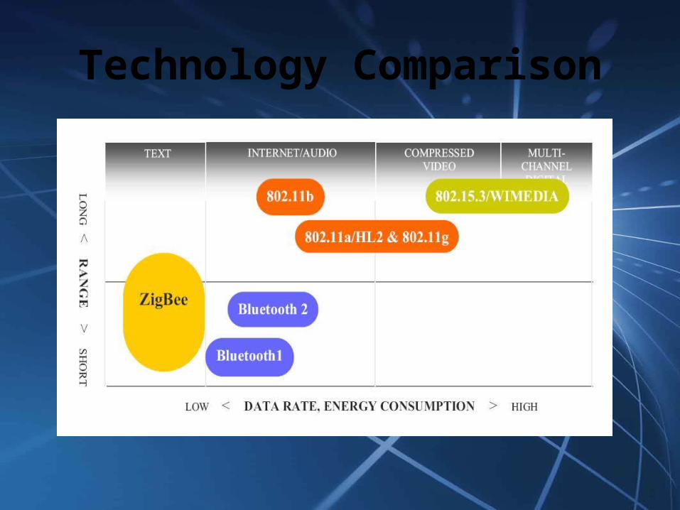
Technology Comparison

ZigBee
We decided to use ZigBee for our project for a number of reasons
•Low power requirement•Compact size•Good range•Perfect for small data transfer•Relatively low complexity•Compatible with Microsoft Windows•Low cost

Personal Area Network 802.15.
• Specializes in Wireless PAN (Personal Area Network) standards
• 802.15.1 – (Bluetooth)• 802.15.2 – Deals with coexistence of Wireless
LAN (802.11) and Wireless PAN• 802.15.3 – High-rate WPAN standards (Wireless
USB)• 802.15.4 – (ZigBee) low-data rate, low-power
networks
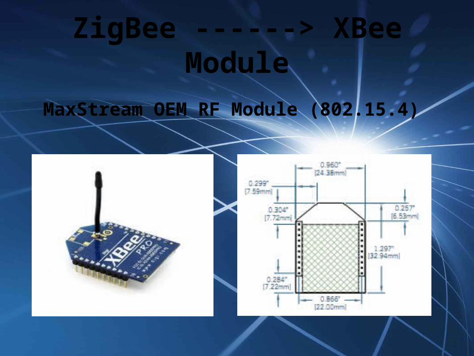
ZigBee ------> XBee Module
MaxStream OEM RF Module (802.15.4)

XBee Specifications• The XBee module costs $39.00 per unit. • It runs at 2.4 GHz. • Input voltage(operating voltage) is 3.3V.• The current:
• when it is receiving data is 50mA, • while it is transmitting the current is 45mA • while it is in power-down mode it runs below 10µA.
• Its sensitivity is at -92dBm. • The chips operating temperature has a range between -40*
and +85*C

Channel Spacing
In the 2.4GHz band, each channel is about 3MHz wide

PIC and XBee
• PIC 18 series have UART interface• The XBee module can be directly connected to
the microcontroller.• For successful serial communication, the
UART’s must be configured with the same baud rate, parity, start bits, stop bits, and data bits. On the microcontroller, pin 26 is for transmission and pin 27 is for receiving and are connected to pin 3 and pin 2 on the Xbee chip respectively.

PIC and XBee connection(Transmitter)
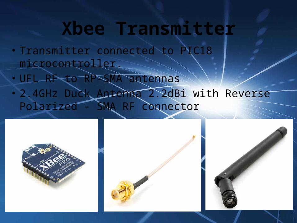
Xbee Transmitter• Transmitter connected to PIC18 microcontroller.• UFL RF to RP-SMA antennas• 2.4GHz Duck Antenna 2.2dBi with Reverse
Polarized - SMA RF connector

ReceiverFTDI Cable
Serial to USB interface
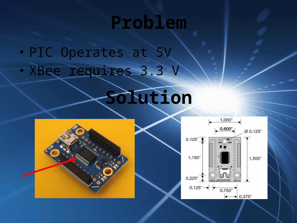
• PIC Operates at 5V• XBee requires 3.3 V
Problem
Solution

Configure
• Update the modules using X-CTU• X-CTU can be downloaded for free• Configure the transmitter• Allows to read data in a certain way from PIC• Using the AT command mode is the how the
XBee chip will be programmed.• AT commands deal with all things from setting
the sleep mode to resetting the chip.• Assign a PAN ID for transmitter and receiver
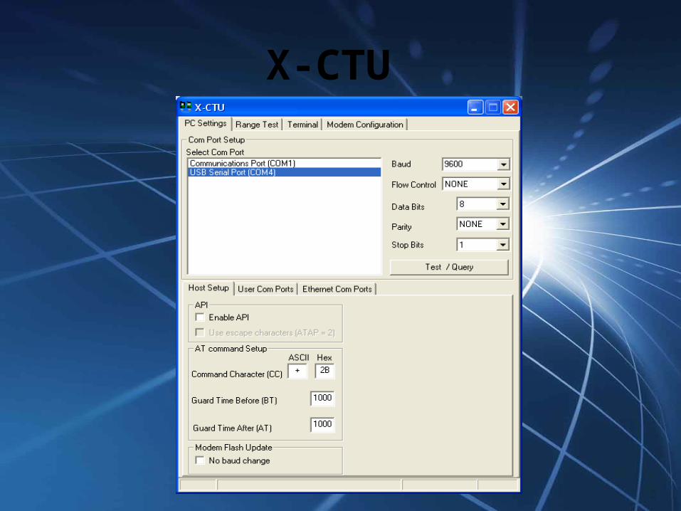
X-CTU

Data Display
Data collected from XBee can be translatedthrough “Python”
ORWe can use “Energy Logger”

BudgetParts List
Part Cost
12 - Solar Panels $7,344.00
1 - Inverter $1,700.00
12 - Current Sensor $56.76
12 - Temperature Sensor $30.12
RJ45 Cable $1.15/ft or $1.00/10ft
Microcontroller $3.26
Wireless $60.00
Solar power Charge Controller $150
2 - 12V 21AH Batteries $85
Miscellaneous Parts $400
PCB Boards $660
Overall $10,489.14