programmable logic controllers - switches unlimitedprogrammable logic controllers microsmart pentra...
TRANSCRIPT
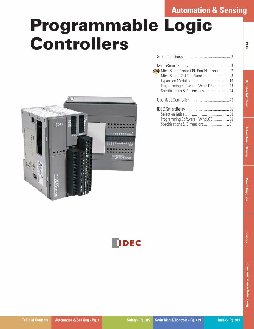
Table of Contents Automation & Sensing - Pg. 1 Safety - Pg. 315 Switching & Controls - Pg. 439 Index - Pg. 911
For more information on this product family, visit our website. Additional resources include:
• New and updated product information • Downloadable software demos & upgrades • Part confi guration tool & cross reference • Online stock check & ordering • IDEC fi eld sales & distributor search • Online literature request
• Downloadable manuals & CAD drawings • Manufacturer’s suggested retail price list • Product training schedule & locations • Advertising & trade show schedules • Press releases & FAQs
PLC
sO
perator InterfacesA
utomation S
oftware
Pow
er Supplies
Sensors
Com
munication &
Netw
orking
Automation & Sensing
www.idec.com/plc
Selection Guide ...............................................2
MicroSmart Family ..........................................3MicroSmart Pentra CPU Part Numbers ..............7MicroSmart CPU Part Numbers .........................8Expansion Modules ..........................................10Programming Software - WindLDR .................23Specifi cations & Dimensions ...........................24
OpenNet Controller .......................................45
IDEC SmartRelay ...........................................56Selection Guide ................................................58Programming Software - WindLGC .................60Specifi cations & Dimensions ...........................61
Programmable Logic Controllers
NEW
Selection Guide
2 www.idec.com
PLC
sO
pera
tor
Inte
rfac
esA
utom
atio
n S
oftw
are
Pow
er S
uppl
ies
Sen
sors
Com
mun
icat
ion
& N
etw
orki
ng
Programmable Logic Controllers
Selection Guide
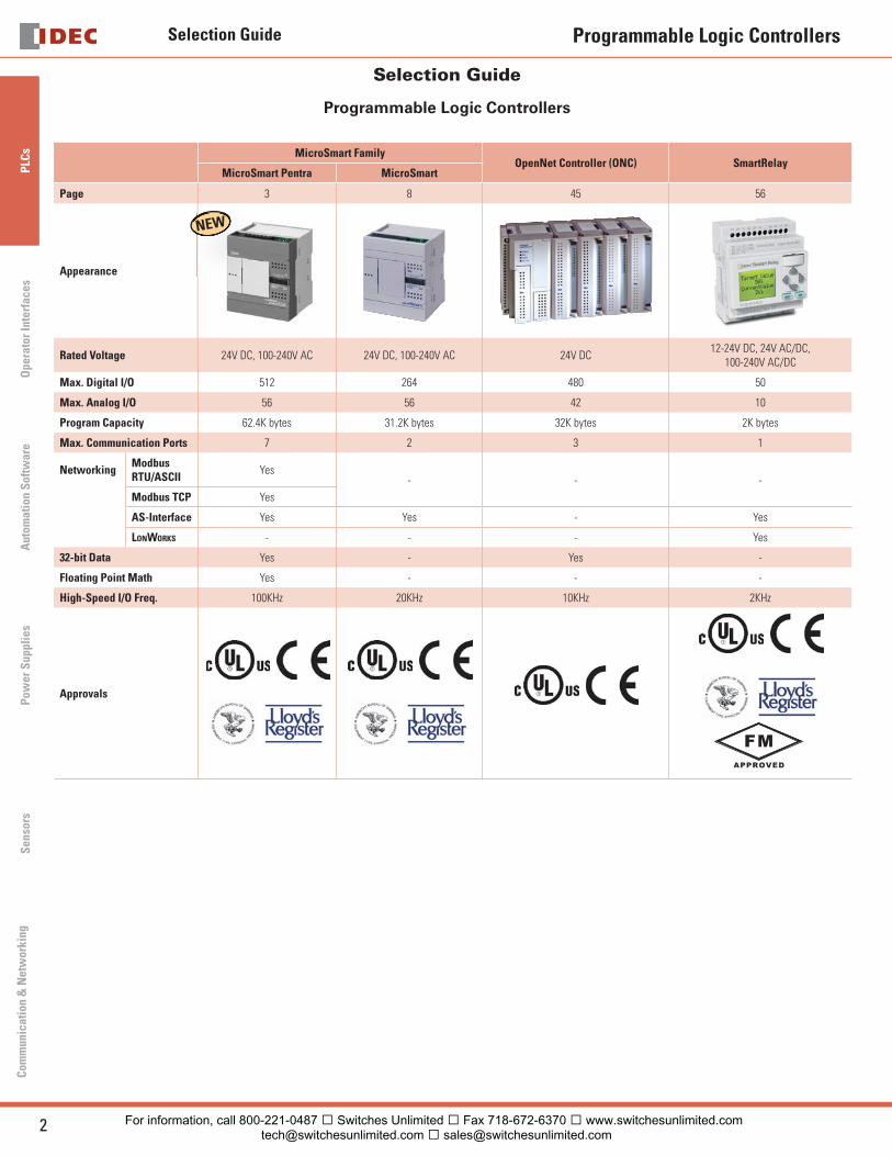
Programmable Logic Controllers
MicroSmart FamilyOpenNet Controller (ONC) SmartRelay
MicroSmart Pentra MicroSmart
Page 3 8 45 56
Appearance
Rated Voltage 24V DC, 100-240V AC 24V DC, 100-240V AC 24V DC12-24V DC, 24V AC/DC,
100-240V AC/DC
Max. Digital I/O 512 264 480 50
Max. Analog I/O 56 56 42 10
Program Capacity 62.4K bytes 31.2K bytes 32K bytes 2K bytes
Max. Communication Ports 7 2 3 1
NetworkingModbus RTU/ASCII
Yes- - -
Modbus TCP Yes
AS-Interface Yes Yes - Yes
LONWORKS - - - Yes
32-bit Data Yes - Yes -
Floating Point Math Yes - - -
High-Speed I/O Freq. 100KHz 20KHz 10KHz 2KHz
Approvals
FM
APPROVED
NEW
For information, call 800-221-0487 � Switches Unlimited � Fax 718-672-6370 � www.switchesunlimited.com [email protected] � [email protected]
MicroSmart Series
3USA: 800-262-IDEC Canada: 888-317-IDEC
PLC
sO
perator InterfacesA
utomation S
oftware
Pow
er Supplies
Sensors
Com
munication &
Netw
orking
Programmable Logic Controllers
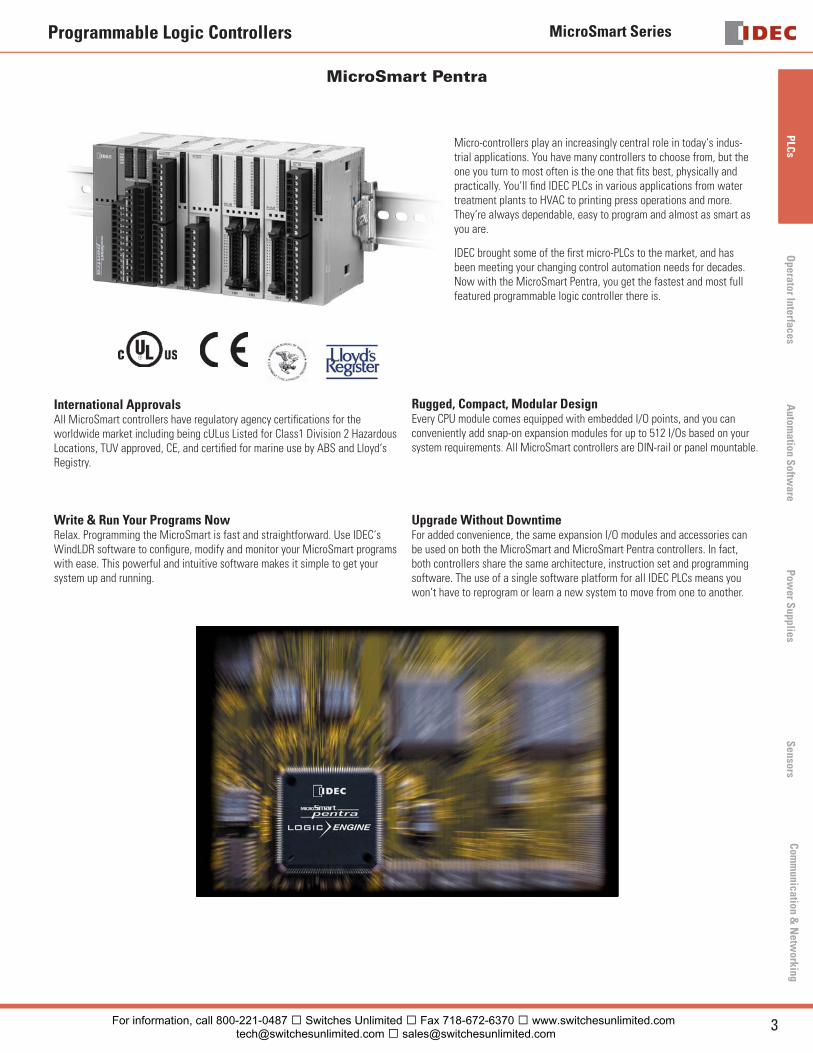
MicroSmart Pentra
Micro-controllers play an increasingly central role in today‘s indus-trial applications. You have many controllers to choose from, but the one you turn to most often is the one that fi ts best, physically and practically. You‘ll fi nd IDEC PLCs in various applications from water treatment plants to HVAC to printing press operations and more. They‘re always dependable, easy to program and almost as smart as you are.
IDEC brought some of the fi rst micro-PLCs to the market, and has been meeting your changing control automation needs for decades. Now with the MicroSmart Pentra, you get the fastest and most full featured programmable logic controller there is.
International ApprovalsAll MicroSmart controllers have regulatory agency certifi cations for the worldwide market including being cULus Listed for Class1 Division 2 Hazardous Locations, TUV approved, CE, and certifi ed for marine use by ABS and Lloyd‘s Registry.
Rugged, Compact, Modular DesignEvery CPU module comes equipped with embedded I/O points, and you can conveniently add snap-on expansion modules for up to 512 I/Os based on your system requirements. All MicroSmart controllers are DIN-rail or panel mountable.
Write & Run Your Programs NowRelax. Programming the MicroSmart is fast and straightforward. Use IDEC‘s WindLDR software to confi gure, modify and monitor your MicroSmart programs with ease. This powerful and intuitive software makes it simple to get your system up and running.
Upgrade Without DowntimeFor added convenience, the same expansion I/O modules and accessories can be used on both the MicroSmart and MicroSmart Pentra controllers. In fact, both controllers share the same architecture, instruction set and programming software. The use of a single software platform for all IDEC PLCs means you won‘t have to reprogram or learn a new system to move from one to another.
For information, call 800-221-0487 � Switches Unlimited � Fax 718-672-6370 � www.switchesunlimited.com [email protected] � [email protected]
MicroSmart Series
4 www.idec.com
PLC
sO
pera
tor
Inte
rfac
esA
utom
atio
n S
oftw
are
Pow
er S
uppl
ies
Sen
sors
Com
mun
icat
ion
& N
etw
orki
ng
Programmable Logic Controllers
MicroSmart Pentra Performance
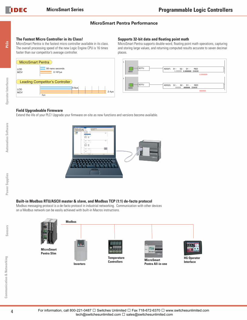
The Fastest Micro Controller in its Class!MicroSmart Pentra is the fastest micro controller available in its class. The overall processing speed of the new Logic Engine CPU is 16 times faster than our competitor’s average controller.
MicroSmart Pentra
LOD 56 nano seconds
0.167μs
0.9μs
2.4μs0μs
MOV
LODMOV
Leading Competitor’s Controller
Supports 32-bit data and fl oating point math MicroSmart Pentra supports double-word, fl oating point math operations, capturing and storing large values, and returning computed results accurate to seven decimal places.
I0000
1
SOTU ADD(F) S1 - S2 - D1 - RED1.111111 8.888888 D0000
9.999999
I0000
1
SOTU ADD(D) S1 - S2 - D1 - RED111111 888888 D0000
999999
Field Upgradeable FirmwareExtend the life of your PLC! Upgrade your fi rmware on-site as new functions and versions become available.
Built-in Modbus RTU/ASCII master & slave, and Modbus TCP (1:1) de-facto protocolModbus messaging protocol is a de-facto protocol in industrial networking. Communication with other devices on a Modbus network can be easily achieved with built-in Macros instructions.
Modbus
MicroSmart Pentra Slim
Inverters
Temperature Controllers MicroSmart
Pentra All-in-one
HG Operator Interface
For information, call 800-221-0487 � Switches Unlimited � Fax 718-672-6370 � www.switchesunlimited.com [email protected] � [email protected]
MicroSmart Series
5USA: 800-262-IDEC Canada: 888-317-IDEC
PLC
sO
perator InterfacesA
utomation S
oftware
Pow
er Supplies
Sensors
Com
munication &
Netw
orking
Programmable Logic Controllers
MicroSmart Pentra Performance
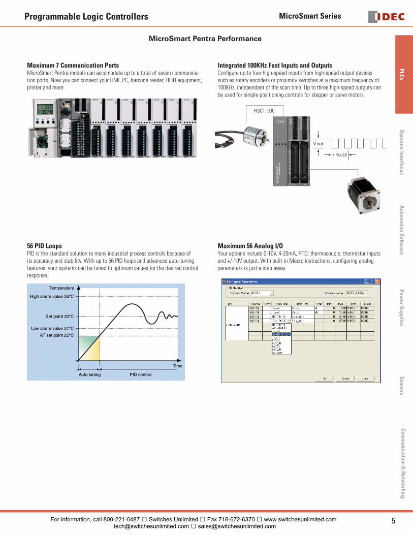
Maximum 7 Communication PortsMicroSmart Pentra models can accomodate up to a total of seven communica-tion ports. Now you can connect your HMI, PC, barcode reader, RFID equipment, printer and more.
Integrated 100KHz Fast Inputs and OutputsConfi gure up to four high-speed inputs from high-speed output devices such as rotary encoders or proximity switches at a maximum frequency of 100KHz, independent of the scan time. Up to three high-speed outputs can be used for simple positioning controls for stepper or servo motors.
V out
1 PULSE
HSC1: 930
56 PID LoopsPID is the standard solution to many industrial process controls because of its accuracy and stability. With up to 56 PID loops and advanced auto-tuning features, your systems can be tuned to optimum values for the desired control response.
Maximum 56 Analog I/OYour options include 0-10V, 4-20mA, RTD, thermocouple, thermistor inputs and +/-10V output. With built-in Macro instructions, confi guring analog parameters is just a step away.
For information, call 800-221-0487 � Switches Unlimited � Fax 718-672-6370 � www.switchesunlimited.com [email protected] � [email protected]
MicroSmart Series
6 www.idec.com
PLC
sO
pera
tor
Inte
rfac
esA
utom
atio
n S
oftw
are
Pow
er S
uppl
ies
Sen
sors
Com
mun
icat
ion
& N
etw
orki
ng
Programmable Logic Controllers
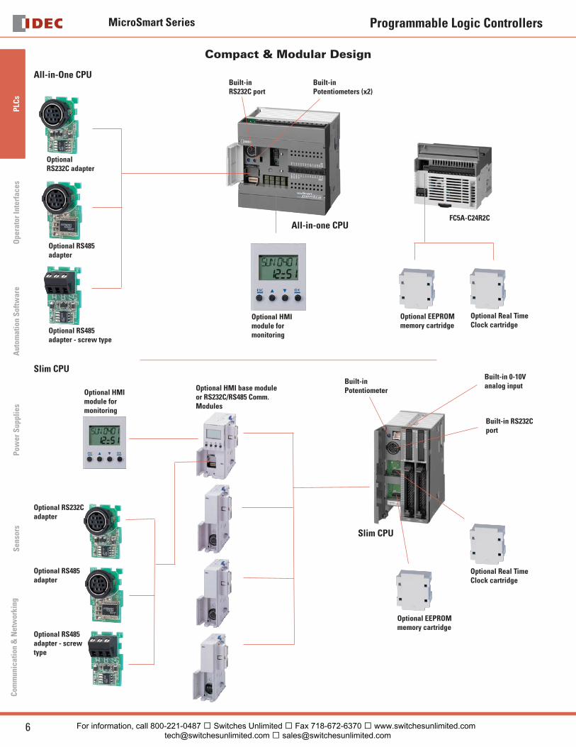
Compact & Modular Design
All-in-One CPU
Optional EEPROM memory cartridge
Optional Real Time Clock cartridge
FC5A-C24R2C
Optional HMI module for monitoring
Built-in RS232C port
Built-inPotentiometers (x2)
Optional RS232C adapter
Optional RS485 adapter
Optional RS485 adapter - screw type
All-in-one CPU
Slim CPU
Optional EEPROM memory cartridge
Optional Real Time Clock cartridge
Built-in RS232C port
Built-in 0-10V analog input
Built-in Potentiometer
Slim CPU
Optional HMI base module or RS232C/RS485 Comm. Modules
Optional HMI module for monitoring
Optional RS232C adapter
Optional RS485 adapter
Optional RS485 adapter - screw type
For information, call 800-221-0487 � Switches Unlimited � Fax 718-672-6370 � www.switchesunlimited.com [email protected] � [email protected]
MicroSmart Series
7USA: 800-262-IDEC Canada: 888-317-IDEC
PLC
sO
perator InterfacesA
utomation S
oftware
Pow
er Supplies
Sensors
Com
munication &
Netw
orking
Programmable Logic Controllers
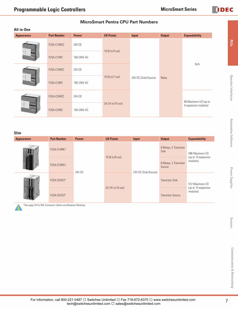
MicroSmart Pentra CPU Part Numbers
All-in-One
Appearance Part Number Power I/O Points Input Output Expandability
FC5A-C10R2C 24V DC
10 (6 in/4 out)
24V DC (Sink/Source) Relay
N/A
FC5A-C10R2 100-240V AC
FC5A-C16R2C 24V DC
16 (9 in/7 out)
FC5A-C16R2 100-240V AC
FC5A-C24R2C 24V DC
24 (14 in/10 out)88 Maximum I/O (up to 4 expansion modules)
FC5A-C24R2 100-240V AC
Slim
Appearance Part Number Power I/O Points Input Output Expandability
FC5A-D16RK1
24V DC
16 (8 in/8 out)
24V DC (Sink/Source)
6 Relays, 2 Transistor Sink
496 Maximum I/O (up to 15 expansion modules)
FC5A-D16RS16 Relays, 2 Transistor Source
FC5A-D32K3*
32 (16 in/16 out)
Transistor Sink512 Maximum I/O (up to 15 expansion modules)
FC5A-D32S3* Transistor Source
*See page 20 for MIL Connector Cables and Breakout Modules.
For information, call 800-221-0487 � Switches Unlimited � Fax 718-672-6370 � www.switchesunlimited.com [email protected] � [email protected]
MicroSmart Series
8 www.idec.com
PLC
sO
pera
tor
Inte
rfac
esA
utom
atio
n S
oftw
are
Pow
er S
uppl
ies
Sen
sors
Com
mun
icat
ion
& N
etw
orki
ng
Programmable Logic Controllers
MicroSmart Performance
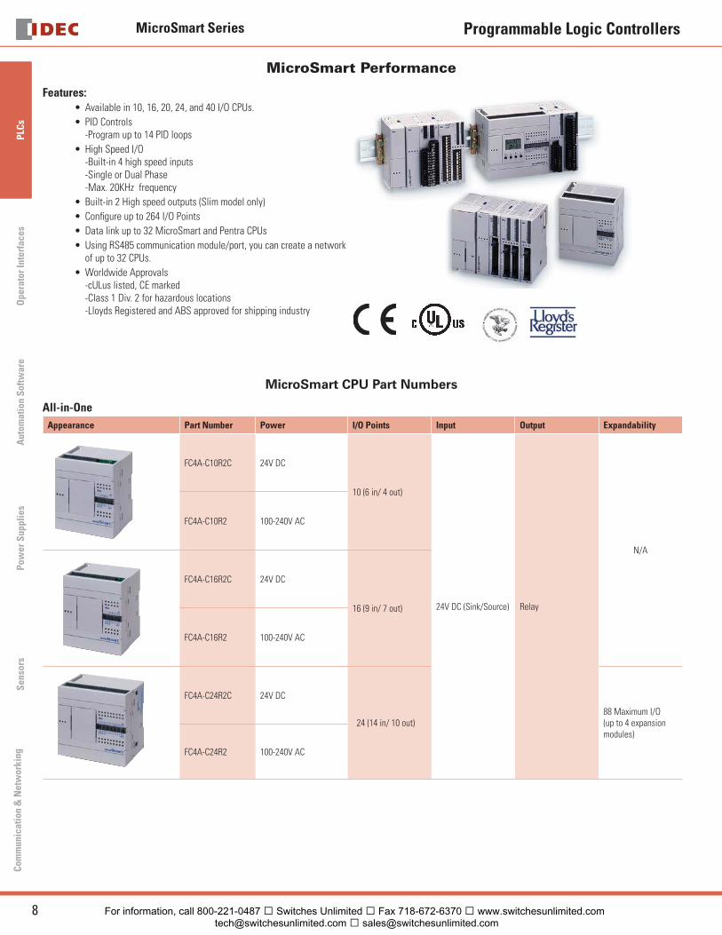
Features:Available in 10, 16, 20, 24, and 40 I/O CPUs.
PID Controls-Program up to 14 PID loops
High Speed I/O-Built-in 4 high speed inputs-Single or Dual Phase-Max. 20KHz frequency
Built-in 2 High speed outputs (Slim model only)
Confi gure up to 264 I/O Points
Data link up to 32 MicroSmart and Pentra CPUs
Using RS485 communication module/port, you can create a network of up to 32 CPUs.
Worldwide Approvals-cULus listed, CE marked-Class 1 Div. 2 for hazardous locations-Lloyds Registered and ABS approved for shipping industry
•
•
•
•
•
•
•
•
MicroSmart CPU Part Numbers
All-in-One
Appearance Part Number Power I/O Points Input Output Expandability
FC4A-C10R2C 24V DC
10 (6 in/ 4 out)
24V DC (Sink/Source) Relay
N/A
FC4A-C10R2 100-240V AC
FC4A-C16R2C 24V DC
16 (9 in/ 7 out)
FC4A-C16R2 100-240V AC
FC4A-C24R2C 24V DC
24 (14 in/ 10 out)88 Maximum I/O (up to 4 expansion modules)
FC4A-C24R2 100-240V AC
For information, call 800-221-0487 � Switches Unlimited � Fax 718-672-6370 � www.switchesunlimited.com [email protected] � [email protected]
MicroSmart Series
9USA: 800-262-IDEC Canada: 888-317-IDEC
PLC
sO
perator InterfacesA
utomation S
oftware
Pow
er Supplies
Sensors
Com
munication &
Netw
orking
Programmable Logic Controllers
MicroSmart CPU Part Numbers
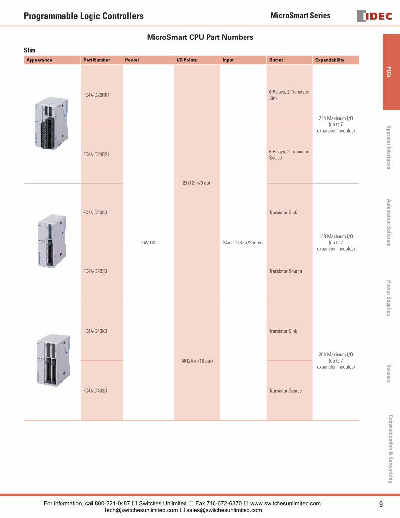
Slim
Appearance Part Number Power I/O Points Input Output Expandability
FC4A-D20RK1
24V DC
20 (12 in/8 out)
24V DC (Sink/Source)
6 Relays, 2 Transistor Sink
244 Maximum I/O (up to 7
expansion modules)
FC4A-D20RS16 Relays, 2 Transistor Source
FC4A-D20K3 Transistor Sink
148 Maximum I/O (up to 7
expansion modules)
FC4A-D20S3 Transistor Source
FC4A-D40K3
40 (24 in/16 out)
Transistor Sink
264 Maximum I/O (up to 7
expansion modules)
FC4A-D40S3 Transistor Source
For information, call 800-221-0487 � Switches Unlimited � Fax 718-672-6370 � www.switchesunlimited.com [email protected] � [email protected]
MicroSmart Series
10 www.idec.com
PLC
sO
pera
tor
Inte
rfac
esA
utom
atio
n S
oftw
are
Pow
er S
uppl
ies
Sen
sors
Com
mun
icat
ion
& N
etw
orki
ng
Programmable Logic Controllers
Digital I/O Expansion Modules
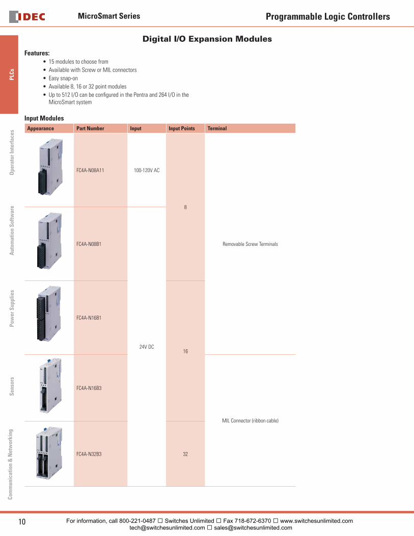
Features:15 modules to choose from
Available with Screw or MIL connectors
Easy snap-on
Available 8, 16 or 32 point modules
Up to 512 I/O can be confi gured in the Pentra and 264 I/O in the MicroSmart system
Input Modules
•
•
•
•
•
Appearance Part Number Input Input Points Terminal
FC4A-N08A11 100-120V AC
8
Removable Screw TerminalsFC4A-N08B1
24V DC
FC4A-N16B1
16
FC4A-N16B3
MIL Connector (ribbon cable)
FC4A-N32B3 32
For information, call 800-221-0487 � Switches Unlimited � Fax 718-672-6370 � www.switchesunlimited.com [email protected] � [email protected]
MicroSmart Series
11USA: 800-262-IDEC Canada: 888-317-IDEC
PLC
sO
perator InterfacesA
utomation S
oftware
Pow
er Supplies
Sensors
Com
munication &
Netw
orking
Programmable Logic Controllers
Digital I/O Expansion Modules
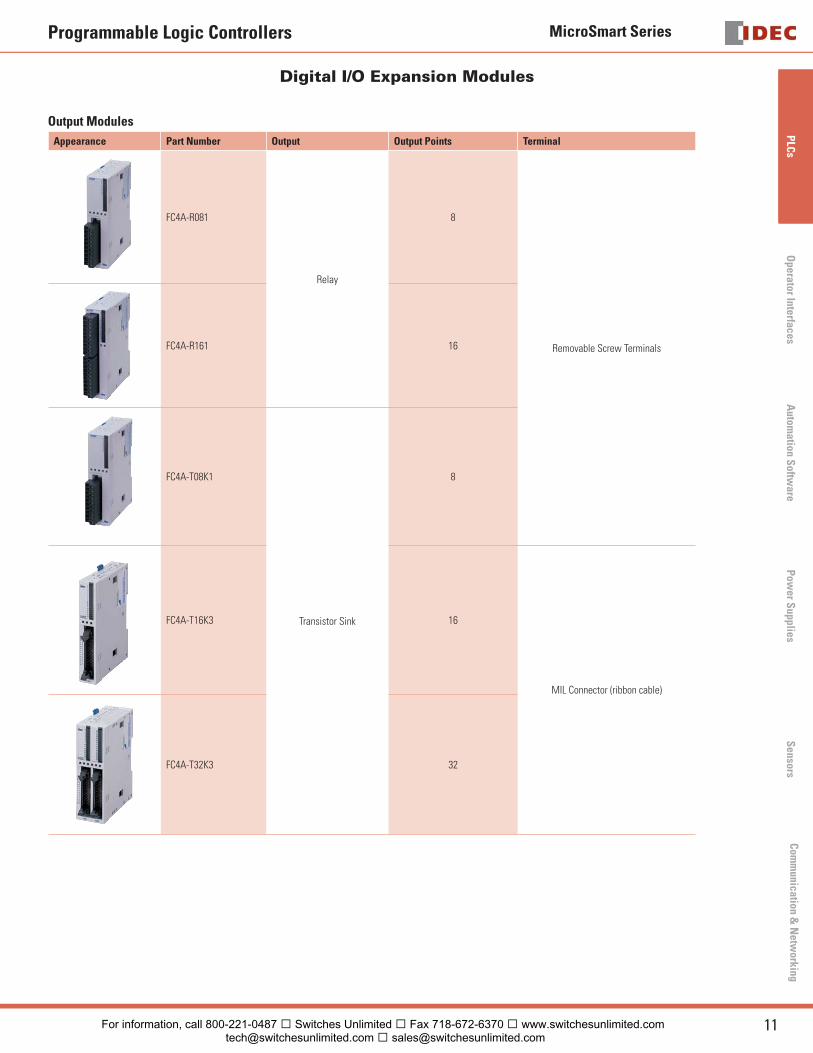
Output Modules
Appearance Part Number Output Output Points Terminal
FC4A-R081
Relay
8
Removable Screw TerminalsFC4A-R161 16
FC4A-T08K1
Transistor Sink
8
FC4A-T16K3 16
MIL Connector (ribbon cable)
FC4A-T32K3 32
For information, call 800-221-0487 � Switches Unlimited � Fax 718-672-6370 � www.switchesunlimited.com [email protected] � [email protected]
MicroSmart Series
12 www.idec.com
PLC
sO
pera
tor
Inte
rfac
esA
utom
atio
n S
oftw
are
Pow
er S
uppl
ies
Sen
sors
Com
mun
icat
ion
& N
etw
orki
ng
Programmable Logic Controllers
Digital I/O Expansion Modules
Output Modules (cont.)
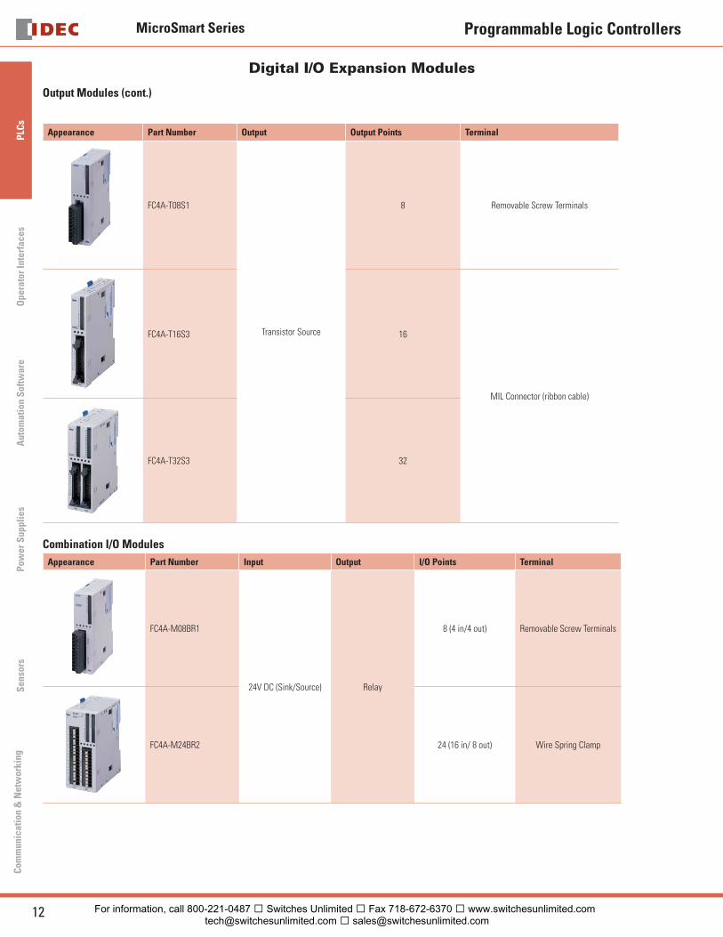
Appearance Part Number Output Output Points Terminal
FC4A-T08S1
Transistor Source
8 Removable Screw Terminals
FC4A-T16S3 16
MIL Connector (ribbon cable)
FC4A-T32S3 32
Combination I/O Modules
Appearance Part Number Input Output I/O Points Terminal
FC4A-M08BR1
24V DC (Sink/Source) Relay
8 (4 in/4 out) Removable Screw Terminals
FC4A-M24BR2 24 (16 in/ 8 out) Wire Spring Clamp
For information, call 800-221-0487 � Switches Unlimited � Fax 718-672-6370 � www.switchesunlimited.com [email protected] � [email protected]
MicroSmart Series
13USA: 800-262-IDEC Canada: 888-317-IDEC
PLC
sO
perator InterfacesA
utomation S
oftware
Pow
er Supplies
Sensors
Com
munication &
Netw
orking
Programmable Logic Controllers
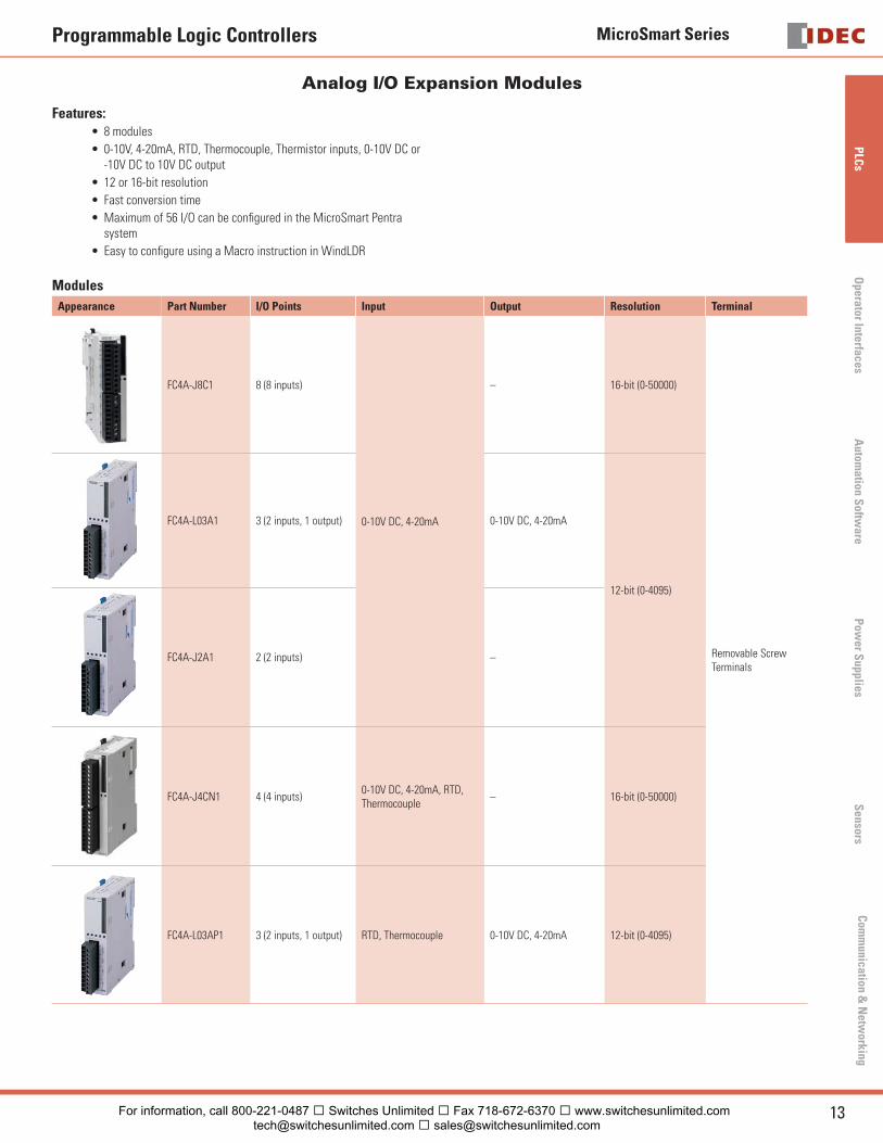
Analog I/O Expansion Modules
Features:8 modules
0-10V, 4-20mA, RTD, Thermocouple, Thermistor inputs, 0-10V DC or -10V DC to 10V DC output
12 or 16-bit resolution
Fast conversion time
Maximum of 56 I/O can be confi gured in the MicroSmart Pentra system
Easy to confi gure using a Macro instruction in WindLDR
Modules
•
•
•
•
•
•
Appearance Part Number I/O Points Input Output Resolution Terminal
FC4A-J8C1 8 (8 inputs)
0-10V DC, 4-20mA
– 16-bit (0-50000)
Removable Screw Terminals
FC4A-L03A1 3 (2 inputs, 1 output) 0-10V DC, 4-20mA
12-bit (0-4095)
FC4A-J2A1 2 (2 inputs) –
FC4A-J4CN1 4 (4 inputs)0-10V DC, 4-20mA, RTD, Thermocouple
– 16-bit (0-50000)
FC4A-L03AP1 3 (2 inputs, 1 output) RTD, Thermocouple 0-10V DC, 4-20mA 12-bit (0-4095)
For information, call 800-221-0487 � Switches Unlimited � Fax 718-672-6370 � www.switchesunlimited.com [email protected] � [email protected]
MicroSmart Series
14 www.idec.com
PLC
sO
pera
tor
Inte
rfac
esA
utom
atio
n S
oftw
are
Pow
er S
uppl
ies
Sen
sors
Com
mun
icat
ion
& N
etw
orki
ng
Programmable Logic Controllers
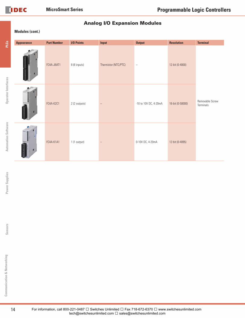
Appearance Part Number I/O Points Input Output Resolution Terminal
FC4A-J8AT1 8 (8 inputs) Thermistor (NTC/PTC) – 12-bit (0-4000)
Removable Screw Terminals FC4A-K2C1 2 (2 outputs) – -10 to 10V DC, 4-20mA 16-bit (0-50000)
FC4A-K1A1 1 (1 output) – 0-10V DC, 4-20mA 12-bit (0-4095)
Analog I/O Expansion Modules
Modules (cont.)
For information, call 800-221-0487 � Switches Unlimited � Fax 718-672-6370 � www.switchesunlimited.com [email protected] � [email protected]
MicroSmart Series
15USA: 800-262-IDEC Canada: 888-317-IDEC
PLC
sO
perator InterfacesA
utomation S
oftware
Pow
er Supplies
Sensors
Com
munication &
Netw
orking
Programmable Logic Controllers
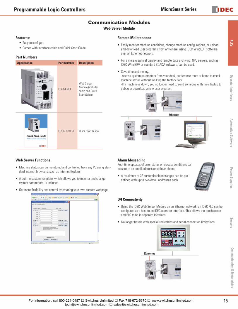
Communication Modules Web Server Module
Features:Easy to confi gure
Comes with interface cable and Quick Start Guide
Part Numbers
Appearance Part Number Description
FC4A-ENET
Web Server Module (includes cable and Quick Start Guide)
Quick Start GuideWeb Server Module for MicroSmart PLC
FC9Y-QS100-0 Quick Start Guide
•
•
Remote Maintenance
Easily monitor machine conditions, change machine confi gurations, or upload and download user programs from anywhere, using IDEC WindLDR software over an Ethernet network.
For a more graphical display and remote data archiving, OPC servers, such as IDEC WindSRV or standard SCADA software, can be used.
Save time and money:-Access system parameters from your desk, conference room or home to check machine status without walking the factory fl oor.-If a machine is down, you no longer need to send someone with their laptop to debug or download a new user program.
Ethernet
•
•
•
Web Server Functions
Machine status can be monitored and controlled from any PC using stan-dard internet browsers, such as Internet Explorer.
A built-in custom template, which allows you to monitor and change system parameters, is included.
Get more fl exibility and control by creating your own custom webpage.
•
•
•
Alarm MessagingReal-time updates of error status or process conditions can be sent to an email address or cellular phone.
A maximum of 32 customizable messages can be pre-defi ned with up to two email addresses each.
•
O/I Connectivity
Using the IDEC Web Server Module on an Ethernet network, an IDEC PLC can be confi gured as a host to an IDEC operator interface. This allows the touchscreen and PLC to be in separate locations.
No longer hassle with specialized cables and serial connection limitations.
Ethernet
•
•
For information, call 800-221-0487 � Switches Unlimited � Fax 718-672-6370 � www.switchesunlimited.com [email protected] � [email protected]
MicroSmart Series
16 www.idec.com
PLC
sO
pera
tor
Inte
rfac
esA
utom
atio
n S
oftw
are
Pow
er S
uppl
ies
Sen
sors
Com
mun
icat
ion
& N
etw
orki
ng
Programmable Logic Controllers
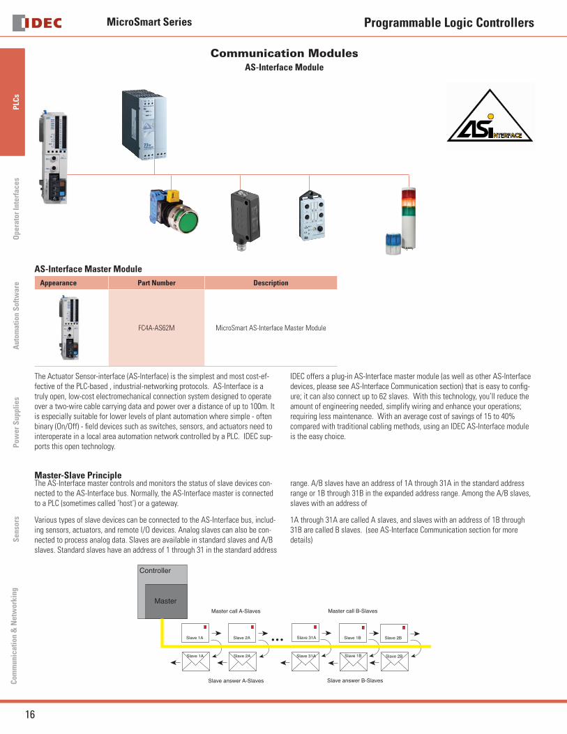
Communication Modules AS-Interface Module
AS-Interface Master Module
Appearance Part Number Description
FC4A-AS62M MicroSmart AS-Interface Master Module
The Actuator Sensor-interface (AS-Interface) is the simplest and most cost-ef-fective of the PLC-based , industrial-networking protocols. AS-Interface is a truly open, low-cost electromechanical connection system designed to operate over a two-wire cable carrying data and power over a distance of up to 100m. It is especially suitable for lower levels of plant automation where simple - often binary (On/Off) - fi eld devices such as switches, sensors, and actuators need to interoperate in a local area automation network controlled by a PLC. IDEC sup-ports this open technology.
IDEC offers a plug-in AS-Interface master module (as well as other AS-Interface devices, please see AS-Interface Communication section) that is easy to confi g-ure; it can also connect up to 62 slaves. With this technology, you’ll reduce the amount of engineering needed, simplify wiring and enhance your operations; requiring less maintenance. With an average cost of savings of 15 to 40% compared with traditional cabling methods, using an IDEC AS-Interface module is the easy choice.
Master-Slave PrincipleThe AS-Interface master controls and monitors the status of slave devices con-nected to the AS-Interface bus. Normally, the AS-Interface master is connected to a PLC (sometimes called ‘host’) or a gateway.
Various types of slave devices can be connected to the AS-Interface bus, includ-ing sensors, actuators, and remote I/O devices. Analog slaves can also be con-nected to process analog data. Slaves are available in standard slaves and A/B slaves. Standard slaves have an address of 1 through 31 in the standard address
range. A/B slaves have an address of 1A through 31A in the standard address range or 1B through 31B in the expanded address range. Among the A/B slaves, slaves with an address of
1A through 31A are called A slaves, and slaves with an address of 1B through 31B are called B slaves. (see AS-Interface Communication section for more details)
Controller
MasterMaster call A-Slaves Master call B-Slaves
Slave answer A-Slaves Slave answer B-Slaves
Slave 1A Slave 2A Slave 31A Slave 1B Slave 2B
Slave 1A Slave 2A Slave 31A Slave 1B Slave 2B
MicroSmart Series
17USA: 800-262-IDEC Canada: 888-317-IDEC
PLC
sO
perator InterfacesA
utomation S
oftware
Pow
er Supplies
Sensors
Com
munication &
Netw
orking
Programmable Logic Controllers
AS-Interface Module con’t
High Reliability and SecurityThe AS-Interface employs a transfer process of high reliability and high security. The master monitors the AS-Interface power supply voltage and data transmit-ted on the line, and detects slave failures and data errors. Even when a slave is replaced or a new slave is added during operation, the master can continue uninterrupted communication with other active slaves on the bus.
MicroSmart AS-Interface Master Module — The Right ChoiceCompliant with AS-Interface Ver. 2.1 specifi cationsDigital and analog slaves can be connected.Confi guration and slave monitoring can be done using the LED indicators and pushbuttons on the font panel as well as using WindLDR software.Maximum of 2 AS-Interface master modules can be used in the MicroSmart Pentra system.
•••
•
AS-Interface Bus Topology and Maximum LengthThe AS-Interface bus topology is fl exible, and you can wire the bus freely ac-cording to your requirements. Bus length can be 100m at the maximum.
AS-Interface — The Perfect SolutionCost EffectiveReliable and SafeReal-time capableEasy to installEasy to expandSafe against interferenceNo limit to the bus structureStar, Line or Tree structure can be constructedUp to 100m, extendable up to 300m using repeaters
•••••••••
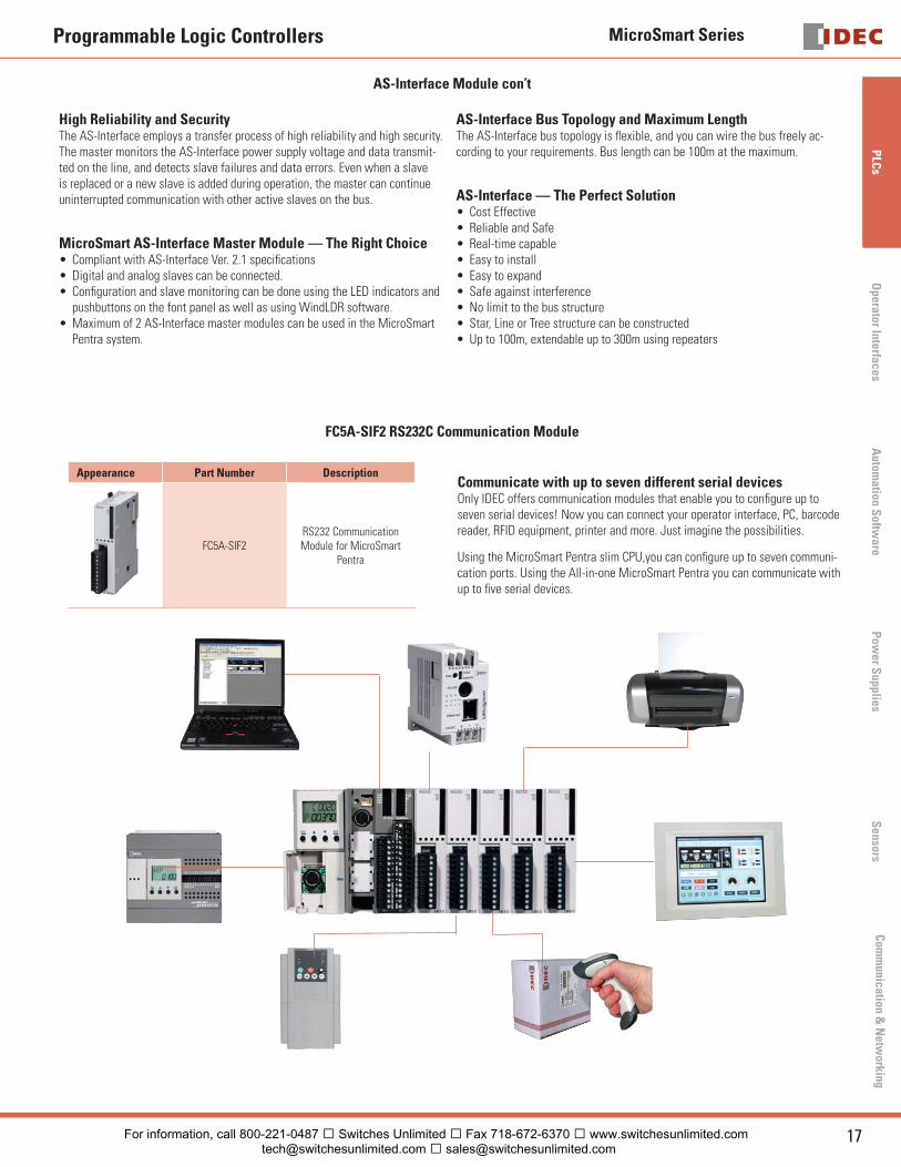
FC5A-SIF2 RS232C Communication Module
Appearance Part Number Description
FC5A-SIF2RS232 Communication Module for MicroSmart
Pentra
Communicate with up to seven different serial devicesOnly IDEC offers communication modules that enable you to confi gure up to seven serial devices! Now you can connect your operator interface, PC, barcode reader, RFID equipment, printer and more. Just imagine the possibilities.
Using the MicroSmart Pentra slim CPU,you can confi gure up to seven communi-cation ports. Using the All-in-one MicroSmart Pentra you can communicate with up to fi ve serial devices.
For information, call 800-221-0487 � Switches Unlimited � Fax 718-672-6370 � www.switchesunlimited.com [email protected] � [email protected]
MicroSmart Series
18 www.idec.com
PLC
sO
pera
tor
Inte
rfac
esA
utom
atio
n S
oftw
are
Pow
er S
uppl
ies
Sen
sors
Com
mun
icat
ion
& N
etw
orki
ng
Programmable Logic Controllers
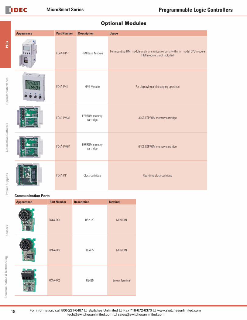
Optional Modules
Appearance Part Number Description Usage
FC4A-HPH1 HMI Base ModuleFor mounting HMI module and communication ports with slim model CPU module
(HMI module is not included)
FC4A-PH1 HMI Module For displaying and changing operands
FC4A-PM32EEPROM memory
cartridge32KB EEPROM memory cartridge
FC4A-PM64EEPROM memory
cartridge64KB EEPROM memory cartridge
FC4A-PT1 Clock cartridge Real-time clock cartridge
Communication Ports
Appearance Part Number Description Terminal
FC4A-PC1 RS232C Mini DIN
FC4A-PC2 RS485 Mini DIN
FC4A-PC3 RS485 Screw Terminal
For information, call 800-221-0487 � Switches Unlimited � Fax 718-672-6370 � www.switchesunlimited.com [email protected] � [email protected]
MicroSmart Series
19USA: 800-262-IDEC Canada: 888-317-IDEC
PLC
sO
perator InterfacesA
utomation S
oftware
Pow
er Supplies
Sensors
Com
munication &
Netw
orking
Programmable Logic Controllers
Optional Modules
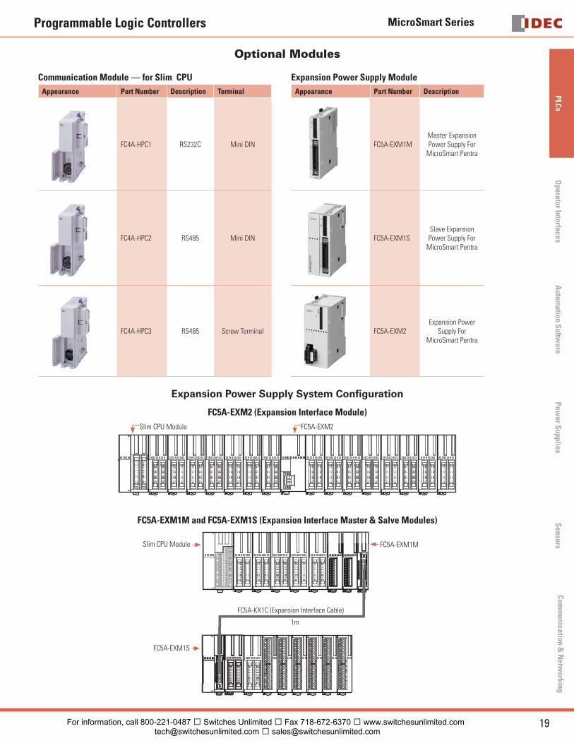
Communication Module — for Slim CPU
Appearance Part Number Description Terminal
FC4A-HPC1 RS232C Mini DIN
FC4A-HPC2 RS485 Mini DIN
FC4A-HPC3 RS485 Screw Terminal
Expansion Power Supply Module
Appearance Part Number Description
FC5A-EXM1MMaster Expansion Power Supply For
MicroSmart Pentra
FC5A-EXM1SSlave Expansion Power Supply For
MicroSmart Pentra
FC5A-EXM2Expansion Power
Supply For MicroSmart Pentra
Expansion Power Supply System Confi guration
FC5A-EXM2 (Expansion Interface Module)
Slim CPU Module FC5A-EXM2
FC5A-EXM1M and FC5A-EXM1S (Expansion Interface Master & Salve Modules)
Slim CPU Module FC5A-EXM1M
FC5A-EXM1S
FC5A-KX1C (Expansion Interface Cable)
1m
For information, call 800-221-0487 � Switches Unlimited � Fax 718-672-6370 � www.switchesunlimited.com [email protected] � [email protected]
MicroSmart Series
20 www.idec.com
PLC
sO
pera
tor
Inte
rfac
esA
utom
atio
n S
oftw
are
Pow
er S
uppl
ies
Sen
sors
Com
mun
icat
ion
& N
etw
orki
ng
Programmable Logic Controllers
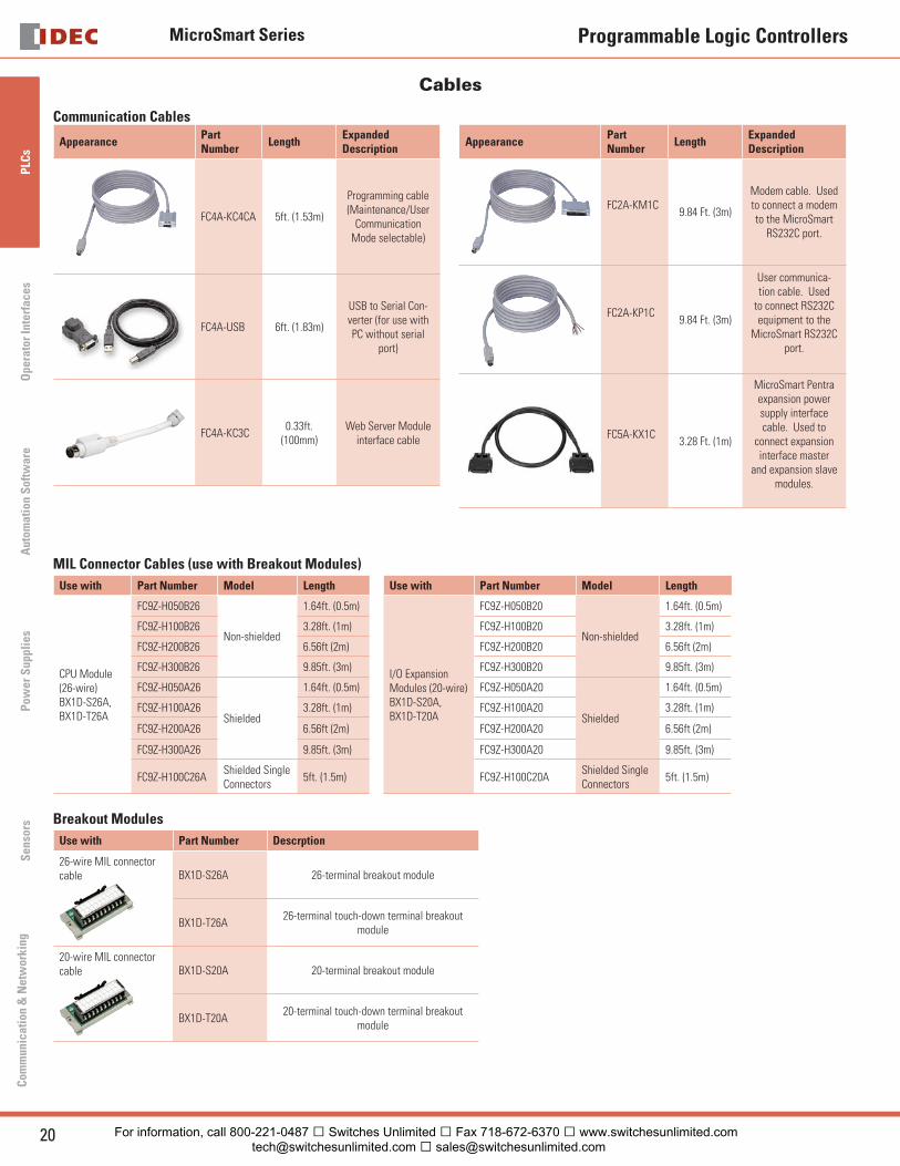
Cables
Communication Cables
Appearance Part Number
LengthExpanded Description
FC4A-KC4CA 5ft. (1.53m)
Programming cable (Maintenance/User
Communication Mode selectable)
FC4A-USB 6ft. (1.83m)
USB to Serial Con-verter (for use with PC without serial
port)
FC4A-KC3C0.33ft.
(100mm)Web Server Module
interface cable
Appearance Part Number
LengthExpanded Description
FC2A-KM1C9.84 Ft. (3m)
Modem cable. Used to connect a modem to the MicroSmart
RS232C port.
FC2A-KP1C9.84 Ft. (3m)
User communica-tion cable. Used
to connect RS232C equipment to the
MicroSmart RS232C port.
FC5A-KX1C3.28 Ft. (1m)
MicroSmart Pentra expansion power supply interface cable. Used to
connect expansion interface master
and expansion slave modules.
MIL Connector Cables (use with Breakout Modules)
Use with Part Number Model Length Use with Part Number Model Length
CPU Module (26-wire)BX1D-S26A, BX1D-T26A
FC9Z-H050B26
Non-shielded
1.64ft. (0.5m)
I/O Expansion Modules (20-wire)BX1D-S20A,BX1D-T20A
FC9Z-H050B20
Non-shielded
1.64ft. (0.5m)
FC9Z-H100B26 3.28ft. (1m) FC9Z-H100B20 3.28ft. (1m)
FC9Z-H200B26 6.56ft (2m) FC9Z-H200B20 6.56ft (2m)
FC9Z-H300B26 9.85ft. (3m) FC9Z-H300B20 9.85ft. (3m)
FC9Z-H050A26
Shielded
1.64ft. (0.5m) FC9Z-H050A20
Shielded
1.64ft. (0.5m)
FC9Z-H100A26 3.28ft. (1m) FC9Z-H100A20 3.28ft. (1m)
FC9Z-H200A26 6.56ft (2m) FC9Z-H200A20 6.56ft (2m)
FC9Z-H300A26 9.85ft. (3m) FC9Z-H300A20 9.85ft. (3m)
FC9Z-H100C26AShielded Single Connectors
5ft. (1.5m) FC9Z-H100C20AShielded Single Connectors
5ft. (1.5m)
Breakout Modules
Use with Part Number Descrption
26-wire MIL connector cable BX1D-S26A 26-terminal breakout module
BX1D-T26A26-terminal touch-down terminal breakout
module
20-wire MIL connector cable BX1D-S20A 20-terminal breakout module
BX1D-T20A20-terminal touch-down terminal breakout
module
For information, call 800-221-0487 � Switches Unlimited � Fax 718-672-6370 � www.switchesunlimited.com [email protected] � [email protected]
MicroSmart Series
21USA: 800-262-IDEC Canada: 888-317-IDEC
PLC
sO
perator InterfacesA
utomation S
oftware
Pow
er Supplies
Sensors
Com
munication &
Netw
orking
Programmable Logic Controllers
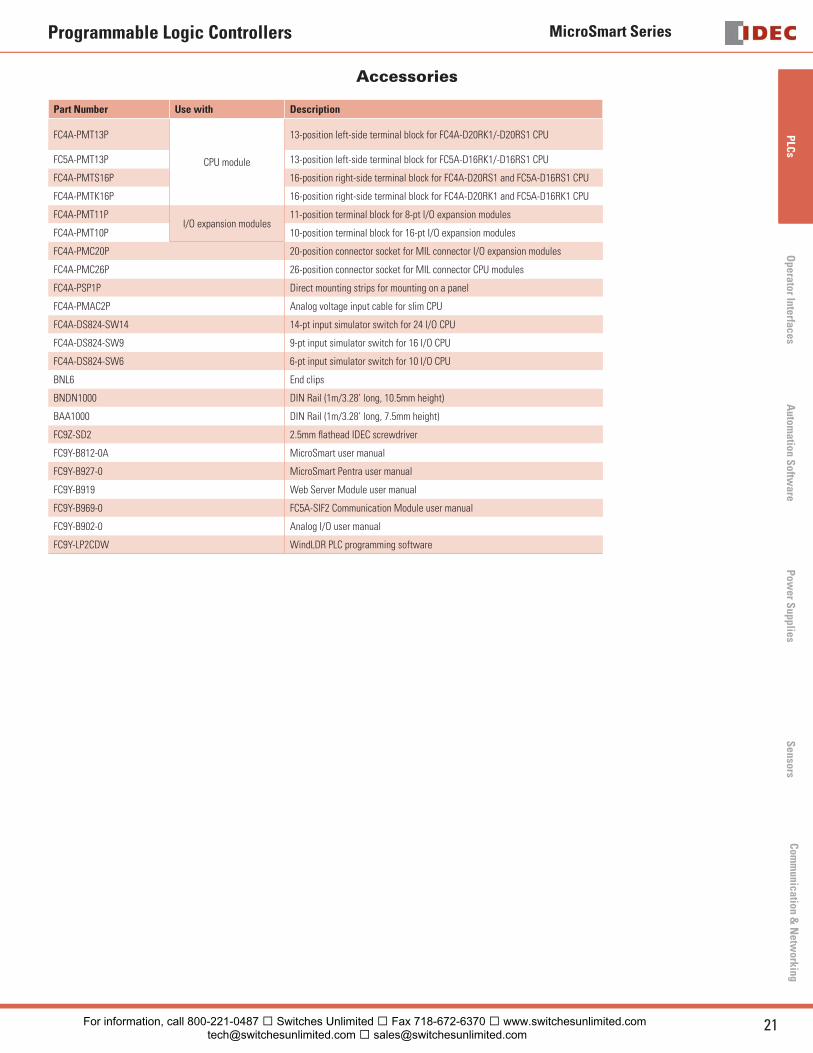
Accessories
Part Number Use with Description
FC4A-PMT13P
CPU module
13-position left-side terminal block for FC4A-D20RK1/-D20RS1 CPU
FC5A-PMT13P 13-position left-side terminal block for FC5A-D16RK1/-D16RS1 CPU
FC4A-PMTS16P 16-position right-side terminal block for FC4A-D20RS1 and FC5A-D16RS1 CPU
FC4A-PMTK16P 16-position right-side terminal block for FC4A-D20RK1 and FC5A-D16RK1 CPU
FC4A-PMT11PI/O expansion modules
11-position terminal block for 8-pt I/O expansion modules
FC4A-PMT10P 10-position terminal block for 16-pt I/O expansion modules
FC4A-PMC20P 20-position connector socket for MIL connector I/O expansion modules
FC4A-PMC26P 26-position connector socket for MIL connector CPU modules
FC4A-PSP1P Direct mounting strips for mounting on a panel
FC4A-PMAC2P Analog voltage input cable for slim CPU
FC4A-DS824-SW14 14-pt input simulator switch for 24 I/O CPU
FC4A-DS824-SW9 9-pt input simulator switch for 16 I/O CPU
FC4A-DS824-SW6 6-pt input simulator switch for 10 I/O CPU
BNL6 End clips
BNDN1000 DIN Rail (1m/3.28’ long, 10.5mm height)
BAA1000 DIN Rail (1m/3.28’ long, 7.5mm height)
FC9Z-SD2 2.5mm fl athead IDEC screwdriver
FC9Y-B812-0A MicroSmart user manual
FC9Y-B927-0 MicroSmart Pentra user manual
FC9Y-B919 Web Server Module user manual
FC9Y-B969-0 FC5A-SIF2 Communication Module user manual
FC9Y-B902-0 Analog I/O user manual
FC9Y-LP2CDW WindLDR PLC programming software
For information, call 800-221-0487 � Switches Unlimited � Fax 718-672-6370 � www.switchesunlimited.com [email protected] � [email protected]
MicroSmart Series
22 www.idec.com
PLC
sO
pera
tor
Inte
rfac
esA
utom
atio
n S
oftw
are
Pow
er S
uppl
ies
Sen
sors
Com
mun
icat
ion
& N
etw
orki
ng
Programmable Logic Controllers
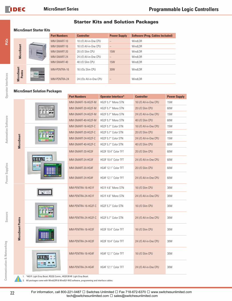
Starter Kits and Solution Packages
MicroSmart Starter Kits
Part Numbers Controller Power Supply Software (Prog. Cables Included)
Mic
roS
mar
t
MM-SMART-10 10 I/O All-in-One CPU – WindLDR
MM-SMART-16 16 I/O All-in-One CPU – WindLDR
MM-SMART-20 20 I/O Slim CPU 15W WindLDR
MM-SMART-24 24 I/O All-in-One CPU – WindLDR
MM-SMART-40 40 I/O Slim CPU 15W WindLDR
Mic
roS
mar
t P
entr
a MM-PENTRA-16 16 I/Os Slim CPU 30W WindLDR
MM-PENTRA-24 24 I/Os All-in-One CPU – WindLDR
MicroSmart Solution Packages
Part Numbers Operator Interface* Controller Power Supply
Mic
roS
mar
t
MM-SMART-16-HG2F-M HG2F 5.7” Mono STN 16 I/O All-in-One CPU 15W
MM-SMART-20-HG2F-M HG2F 5.7” Mono STN 20 I/O Slim CPU 60W
MM-SMART-24-HG2F-M HG2F 5.7” Mono STN 24 I/O All-in-One CPU 15W
MM-SMART-40-HG2F-M HG2F 5.7” Mono STN 40 I/O Slim CPU 60W
MM-SMART-16-HG2F-C HG2F 5.7” Color STN 16 I/O All-in-One CPU 15W
MM-SMART-20-HG2F-C HG2F 5.7” Color STN 20 I/O Slim CPU 60W
MM-SMART-24-HG2F-C HG2F 5.7” Color STN 24 I/O All-in-One CPU 15W
MM-SMART-40-HG2F-C HG2F 5.7” Color STN 40 I/O Slim CPU 60W
MM-SMART-20-HG3F HG3F 10.4” Color TFT 20 I/O Slim CPU 60W
MM-SMART-24-HG3F HG3F 10.4” Color TFT 24 I/O All-in-One CPU 60W
MM-SMART-20-HG4F HG4F 12.1” Color TFT 20 I/O Slim CPU 60W
MM-SMART-24-HG4F HG4F 12.1” Color TFT 24 I/O All-in-One CPU 60W
Mic
roS
mar
t Pen
tra
MM-PENTRA-16-HG1F HG1F 4.6” Mono STN 16 I/O Slim CPU 30W
MM-PENTRA-24-HG1F HG1F 4.6” Mono STN 24 I/O All-in-One CPU 30W
MM-PENTRA-16-HG2F-C HG2F 5.7” Color STN 16 I/O Slim CPU 30W
MM-PENTRA-24-HG2F-C HG2F 5.7” Color STN 24 I/O All-in-One CPU 30W
MM-PENTRA-16-HG3F HG3F 10.4” Color TFT 16 I/O Slim CPU 30W
MM-PENTRA-24-HG3F HG3F 10.4” Color TFT 24 I/O All-in-One CPU 30W
MM-PENTRA-16-HG4F HG4F 12.1” Color TFT 16 I/O Slim CPU 30W
MM-PENTRA-24-HG4F HG4F 12.1” Color TFT 24 I/O All-in-One CPU 30W
1. *HG1F: Light Gray Bezel, RS232 Comm., HG2F/3F/4F: Light Gray Bezel.
2. All packages come with WindLDR & WindO/I-NV2 software, programming and interface cables.
For information, call 800-221-0487 � Switches Unlimited � Fax 718-672-6370 � www.switchesunlimited.com [email protected] � [email protected]

MicroSmart Series
23USA: 800-262-IDEC Canada: 888-317-IDEC
PLC
sO
perator InterfacesA
utomation S
oftware
Pow
er Supplies
Sensors
Com
munication &
Netw
orking
Programmable Logic Controllers
WindLDR
Programming Software
Unique ladder logic programming tool designed to program all IDEC PLCs
Part Number
Part Number Description
FC9Y-LP2CDW WindLDR PLC programming software
Single Platform for all IDEC PLCs
WindLDR is an excellent, long-term investment for your control solutions. It programs every IDEC PLC including the OpenNet Controller, MicroSmart and the fastest micro-controller on the market, MicroSmart Pentra. It’s adaptable to whatever hardware you need today and down the road.
Simple-to-use Editors
Use the tag editor to access and edit coil data. Edit comments and rung com-ments. Simulation mode tests your program in WindLDR to guarantee that it works the way you expected, before downloading it to your PLC.
User-friendly Interfaces
Icon-based toolbars and drag-and-drop functionality make basic ladder program-ming accessible to anyone. But WindLDR also shows you how to display param-eters and settings and how to input your parameters, and the built-in shortcuts and tutorials will keep you on the right track.
Free Lifetime Upgrade
Not only is WindLDR the easiest and most convenient ladder programming software on the market, it also comes with a very special price with no strings attached. Our software comes with a free-lifetime upgrade. That means that you no longer need to spend thousands of dollars for software that has to be renewed every year costing you additional money. Save yourself money by using an IDEC PLC and WindLDR programming software.
For more information, see the Automation Software section.
Visit www.idec.com/downloads for free upgrades or a free 30-day trial version.
For information, call 800-221-0487 � Switches Unlimited � Fax 718-672-6370 � www.switchesunlimited.com [email protected] � [email protected]
MicroSmart Series
24 www.idec.com
PLC
sO
pera
tor
Inte
rfac
esA
utom
atio
n S
oftw
are
Pow
er S
uppl
ies
Sen
sors
Com
mun
icat
ion
& N
etw
orki
ng
Programmable Logic Controllers
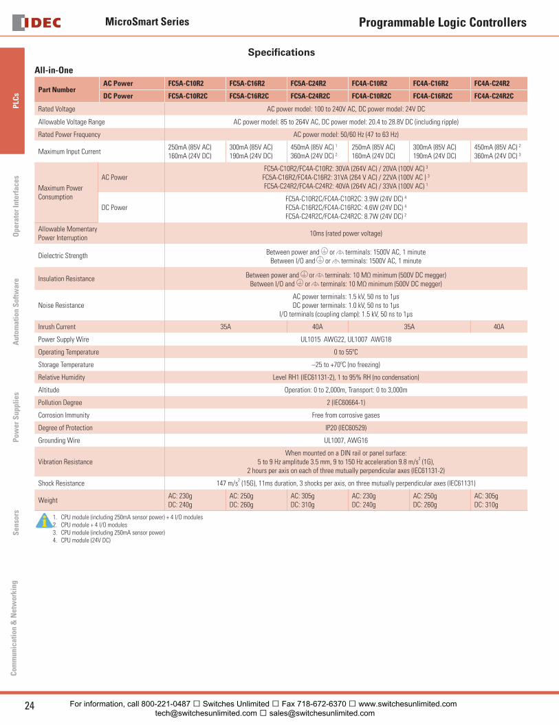
Specifi cations
All-in-One
Part NumberAC Power FC5A-C10R2 FC5A-C16R2 FC5A-C24R2 FC4A-C10R2 FC4A-C16R2 FC4A-C24R2
DC Power FC5A-C10R2C FC5A-C16R2C FC5A-C24R2C FC4A-C10R2C FC4A-C16R2C FC4A-C24R2C
Rated Voltage AC power model: 100 to 240V AC, DC power model: 24V DC
Allowable Voltage Range AC power model: 85 to 264V AC, DC power model: 20.4 to 28.8V DC (including ripple)
Rated Power Frequency AC power model: 50/60 Hz (47 to 63 Hz)
Maximum Input Current250mA (85V AC) 160mA (24V DC)
300mA (85V AC)190mA (24V DC)
450mA (85V AC) 1
360mA (24V DC) 2
250mA (85V AC)160mA (24V DC)
300mA (85V AC)190mA (24V DC)
450mA (85V AC) 2
360mA (24V DC) 3
Maximum PowerConsumption
AC PowerFC5A-C10R2/FC4A-C10R2: 30VA (264V AC) / 20VA (100V AC) 3
FC5A-C16R2/FC4A-C16R2: 31VA (264 V AC) / 22VA (100V AC ) 3
FC5A-C24R2/FC4A-C24R2: 40VA (264V AC) / 33VA (100V AC) 1
DC PowerFC5A-C10R2C/FC4A-C10R2C: 3.9W (24V DC) 4 FC5A-C16R2C/FC4A-C16R2C: 4.6W (24V DC) 4
FC5A-C24R2C/FC4A-C24R2C: 8.7W (24V DC) 2
Allowable MomentaryPower Interruption
10ms (rated power voltage)
Dielectric Strength Between power and or terminals: 1500V AC, 1 minuteBetween I/O and or terminals: 1500V AC, 1 minute
Insulation Resistance Between power and or terminals: 10 MΩ minimum (500V DC megger)Between I/O and or terminals: 10 MΩ minimum (500V DC megger)
Noise ResistanceAC power terminals: 1.5 kV, 50 ns to 1μsDC power terminals: 1.0 kV, 50 ns to 1μs
I/O terminals (coupling clamp): 1.5 kV, 50 ns to 1μs
Inrush Current 35A 40A 35A 40A
Power Supply Wire UL1015 AWG22, UL1007 AWG18
Operating Temperature 0 to 55ºC
Storage Temperature –25 to +70ºC (no freezing)
Relative Humidity Level RH1 (IEC61131-2), 1 to 95% RH (no condensation)
Altitude Operation: 0 to 2,000m, Transport: 0 to 3,000m
Pollution Degree 2 (IEC60664-1)
Corrosion Immunity Free from corrosive gases
Degree of Protection IP20 (IEC60529)
Grounding Wire UL1007, AWG16
Vibration ResistanceWhen mounted on a DIN rail or panel surface:
5 to 9 Hz amplitude 3.5 mm, 9 to 150 Hz acceleration 9.8 m/s2 (1G),
2 hours per axis on each of three mutually perpendicular axes (IEC61131-2)
Shock Resistance 147 m/s2 (15G), 11ms duration, 3 shocks per axis, on three mutually perpendicular axes (IEC61131)
WeightAC: 230gDC: 240g
AC: 250gDC: 260g
AC: 305gDC: 310g
AC: 230gDC: 240g
AC: 250gDC: 260g
AC: 305gDC: 310g
1. CPU module (including 250mA sensor power) + 4 I/O modules2. CPU module + 4 I/O modules3. CPU module (including 250mA sensor power)4. CPU module (24V DC)
For information, call 800-221-0487 � Switches Unlimited � Fax 718-672-6370 � www.switchesunlimited.com [email protected] � [email protected]
MicroSmart Series
25USA: 800-262-IDEC Canada: 888-317-IDEC
PLC
sO
perator InterfacesA
utomation S
oftware
Pow
er Supplies
Sensors
Com
munication &
Netw
orking
Programmable Logic Controllers
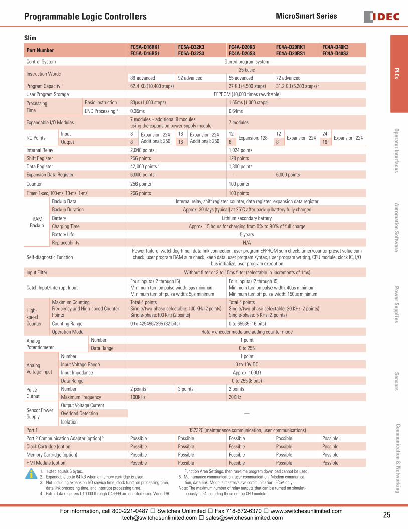
Slim
Part NumberFC5A-D16RK1FC5A-D16RS1
FC5A-D32K3FC5A-D32S3
FC4A-D20K3FC4A-D20S3
FC4A-D20RK1FC4A-D20RS1
FC4A-D40K3FC4A-D40S3
Control System Stored program system
Instruction Words35 basic
88 advanced 92 advanced 55 advanced 72 advanced
Program Capacity 1 62.4 KB (10,400 steps) 27 KB (4,500 steps) 31.2 KB (5,200 steps) 2
User Program Storage EEPROM (10,000 times rewritable)
ProcessingTime
Basic Instruction 83μs (1,000 steps) 1.65ms (1,000 steps)
END Processing 3 0.35ms 0.64ms
Expandable I/O Modules7 modules + additional 8 modules using the expansion power supply module
7 modules
I/O PointsInput 8 Expansion: 224
Additional: 256
16 Expansion: 224Additional: 256
12Expansion: 128
12Expansion: 224
24Expansion: 224
Output 8 16 8 8 16
Internal Relay 2,048 points 1,024 points
Shift Register 256 points 128 points
Data Register 42,000 points 4 1,300 points
Expansion Data Register 6,000 points — 6,000 points
Counter 256 points 100 points
Timer (1-sec, 100-ms, 10-ms, 1-ms) 256 points 100 points
RAM Backup
Backup Data Internal relay, shift register, counter, data register, expansion data register
Backup Duration Approx. 30 days (typical) at 25ºC after backup battery fully charged
Battery Lithium secondary battery
Charging Time Approx. 15 hours for charging from 0% to 90% of full charge
Battery Life 5 years
Replaceability N/A
Self-diagnostic Function Power failure, watchdog timer, data link connection, user program EPPROM sum check, timer/counter preset value sum check, user program RAM sum check, keep data, user program syntax, user program writing, CPU module, clock IC, I/O
bus initialize, user program execution
Input Filter Without fi lter or 3 to 15ms fi lter (selectable in increments of 1ms)
Catch Input/Interrupt InputFour inputs (I2 through I5) Minimum turn on pulse width: 5μs minimumMinimum turn off pulse width: 5μs minimum
Four inputs (I2 through I5) Minimum turn on pulse width: 40μs minimumMinimum turn off pulse width: 150μs minimum
High-speed Counter
Maximum Counting Frequency and High-speed Counter Points
Total 4 pointsSingle/two-phase selectable: 100 KHz (2 points)Single-phase:100 KHz (2 points)
Total 4 pointsSingle/two-phase selectable: 20 KHz (2 points)Single-phase: 5 KHz (2 points)
Counting Range 0 to 4294967295 (32 bits) 0 to 65535 (16 bits)
Operation Mode Rotary encoder mode and adding counter mode
Analog Potentiometer
Number 1 point
Data Range 0 to 255
Analog Voltage Input
Number 1 point
Input Voltage Range 0 to 10V DC
Input Impedance Approx. 100kΩ
Data Range 0 to 255 (8 bits)
PulseOutput
Number 2 points 3 points 2 points
Maximum Frequency 100KHz 20KHz
Sensor Power Supply
Output Voltage Current
—Overload Detection
Isolation
Port 1 RS232C (maintenance communication, user communications)
Port 2 Communication Adapter (option) 5 Possible Possible Possible Possible Possible
Clock Cartridge (option) Possible Possible Possible Possible Possible
Memory Cartridge (option) Possible Possible Possible Possible Possible
HMI Module (option) Possible Possible Possible Possible Possible
1. 1 step equals 6 bytes.2. Expandable up to 64 KB when a memory cartridge is used. 3. Not including expansion I/O service time, clock function processing time,
data link processing time, and interrupt processing time.4. Extra data registers D10000 through D49999 are enabled using WindLDR
Function Area Settings, then run-time program download cannot be used.5. Maintenance communication, user communication, Modem communica-
tion, data link, Modbus master/slave communication (FC5A only).Note: The maximum number of relay outputs that can be turned on simulat-
neously is 54 including those on the CPU module.
For information, call 800-221-0487 � Switches Unlimited � Fax 718-672-6370 � www.switchesunlimited.com [email protected] � [email protected]
MicroSmart Series
26 www.idec.com
PLC
sO
pera
tor
Inte
rfac
esA
utom
atio
n S
oftw
are
Pow
er S
uppl
ies
Sen
sors
Com
mun
icat
ion
& N
etw
orki
ng
Programmable Logic Controllers
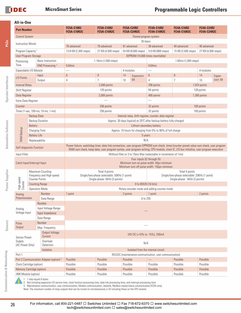
All-in-One
Part NumberFC5A-C10R2FC5A-C10R2C
FC5A-C16R2FC5A-C16R2C
FC5A-C24R2FC5A-C24R2C
FC4A-C10R2FC4A-C10R2C
FC4A-C16R2FC4A-C16R2C
FC4A-C24R2FC4A-C24R2C
Control System Stored program system
Instruction Words35 basic
76 advanced 76 advanced 81 advanced 38 advanced 40 advanced 46 advanced
Program Capacity 1 13.8 KB (2,300 steps) 27 KB (4,500 steps) 54 KB (9,000 steps) 4.8 KB (800 steps) 15 KB (2,500 steps) 27 KB (4,500 steps)
User Program Storage EEPROM (10,000 times rewritable)
ProcessingTime
Basic Instruction 1.16ms (1,000 steps) 1.65ms (1,000 steps)
END Processing 2 0.64ms 0.64ms
Expandable I/O Module — 4 modules — 4 modules
I/O PointsInput 6 9 14 Expansion:
64
6 9 14 Expan-sion: 64Output 4 7 10 4 7 10
Internal Relay 2,048 points 256 points 1,024 points
Shift Register 128 points 64 points 128 points
Data Register 2,000 points 400 points 1,300 points
Extra Data Register — —
Counter 256 points 32 points 100 points
Timer (1-sec, 100-ms, 10-ms, 1-ms) 256 points 32 points 100 points
RAM
Bac
kup
Backup Data Internal relay, shift register, counter, data register
Backup Duration Approx. 30 days (typical) at 25ºC after backup battery fully charged
Battery Lithium secondary battery
Charging Time Approx. 15 hours for charging from 0% to 90% of full charge
Battery Life 5 years
Replaceability N/A
Self-diagnostic Function Power failure, watchdog timer, data link connection, user program EPPROM sum check, timer/counter preset value sum check, user program
RAM sum check, keep data, user program syntax, user program writing, CPU module, clock IC, I/O bus initialize, user program execution
Input Filter Without fi lter or 3 to 15ms fi lter (selectable in increments of 1ms)
Catch Input/Interrupt InputFour inputs (I2 through I5)
Minimum turn on pulse width: 40μs minimumMinimum turn off pulse width: 150μs minimum
Hig
h-sp
eed
Coun
ter
Maximum Counting Frequency and High-speed Counter Points
Total 4 pointsSingle/two-phase selectable: 50KHz (1 point)
Single-phase: 5KHz (3 points)
Total 4 pointsSingle/two-phase selectable: 20KHz (1 point)
Single-phase: 5KHz (3 points)
Counting Range 0 to 65535 (16 bits)
Operation Mode Rotary encoder mode and adding counter mode
AnalogPotentiometer
Number 1 point 2 points 1 point 2 points
Data Range 0 to 255
AnalogVoltage Input
Number
—Input Voltage Range
Input Impedance
Data Range
Pulse Output
Number—
Max. Frequency
Sensor Power Supply (AC Power Only)
Output Voltage Current
24V DC (+10% to -15%), 250mA
Overload Detection
N/A
Isolation Isolated from the internal circuit
Port 1 RS232C (maintenance communication, user communication)
Port 2 Communication Adapter (option) 3 Possible Possible Possible — Possible Possible
Clock Cartridge (option) Possible Possible Possible Possible Possible Possible
Memory Cartridge (option) Possible Possible Possible Possible Possible Possible
HMI Module (option) Possible Possible Possible Possible Possible Possible
1. 1 step equals 6 bytes.2. Not including expansion I/O service time, clock function processing time, data link processing time, and interrupt processing time.3. Maintenance communication, user communication, Modem communication, datalink, Modbus master/slave communication (FC5A only).Note: The maximum number of relay outputs that can be turned on simultaneously is 33 including those on the CPU module.
For information, call 800-221-0487 � Switches Unlimited � Fax 718-672-6370 � www.switchesunlimited.com [email protected] � [email protected]
MicroSmart Series
27USA: 800-262-IDEC Canada: 888-317-IDEC
PLC
sO
perator InterfacesA
utomation S
oftware
Pow
er Supplies
Sensors
Com
munication &
Netw
orking
Programmable Logic Controllers
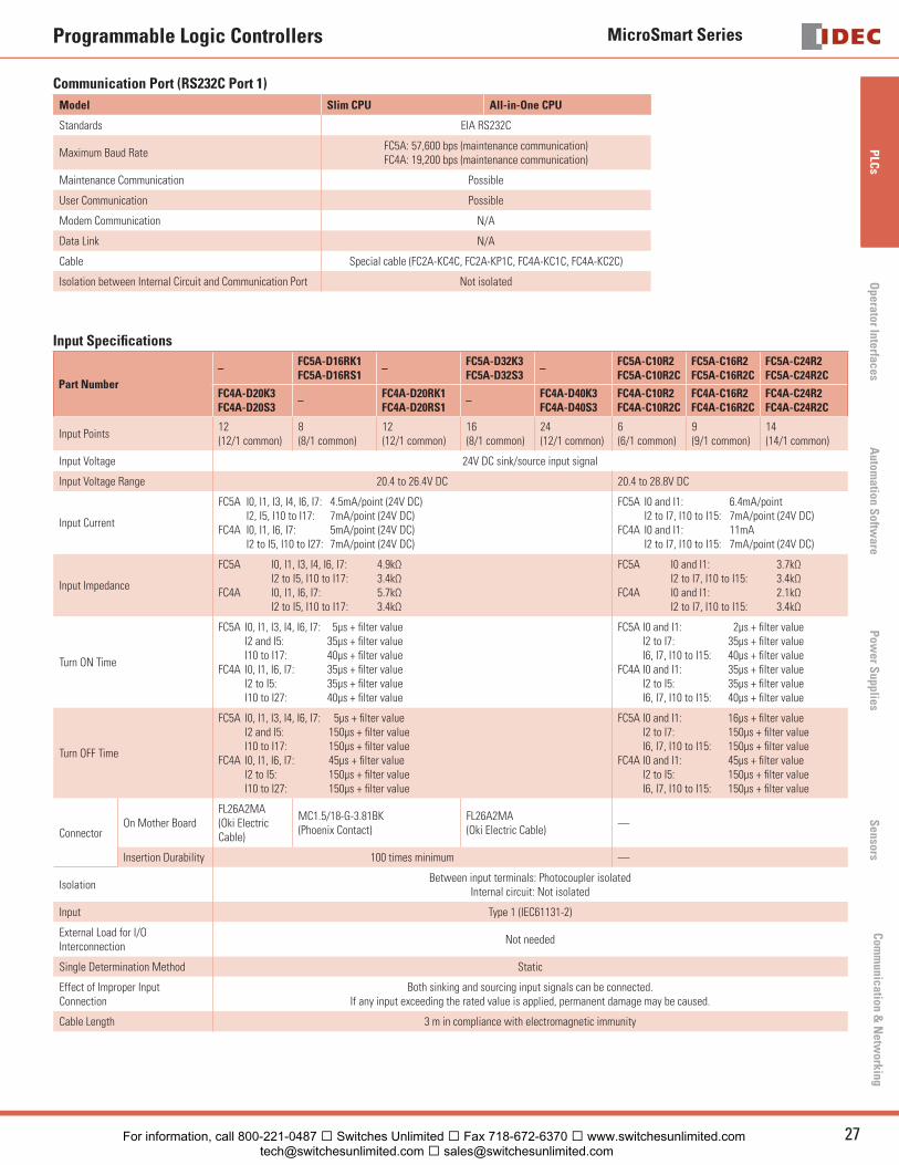
Communication Port (RS232C Port 1)
Model Slim CPU All-in-One CPU
Standards EIA RS232C
Maximum Baud RateFC5A: 57,600 bps (maintenance communication)FC4A: 19,200 bps (maintenance communication)
Maintenance Communication Possible
User Communication Possible
Modem Communication N/A
Data Link N/A
Cable Special cable (FC2A-KC4C, FC2A-KP1C, FC4A-KC1C, FC4A-KC2C)
Isolation between Internal Circuit and Communication Port Not isolated
Input Specifi cations
Part Number
–FC5A-D16RK1FC5A-D16RS1
–FC5A-D32K3FC5A-D32S3
–FC5A-C10R2FC5A-C10R2C
FC5A-C16R2FC5A-C16R2C
FC5A-C24R2FC5A-C24R2C
FC4A-D20K3FC4A-D20S3
–FC4A-D20RK1FC4A-D20RS1
–FC4A-D40K3FC4A-D40S3
FC4A-C10R2FC4A-C10R2C
FC4A-C16R2FC4A-C16R2C
FC4A-C24R2FC4A-C24R2C
Input Points12(12/1 common)
8(8/1 common)
12(12/1 common)
16(8/1 common)
24(12/1 common)
6(6/1 common)
9(9/1 common)
14(14/1 common)
Input Voltage 24V DC sink/source input signal
Input Voltage Range 20.4 to 26.4V DC 20.4 to 28.8V DC
Input Current
FC5A I0, I1, I3, I4, I6, I7: 4.5mA/point (24V DC) I2, I5, I10 to I17: 7mA/point (24V DC)FC4A I0, I1, I6, I7: 5mA/point (24V DC) I2 to I5, I10 to I27: 7mA/point (24V DC)
FC5A I0 and I1: 6.4mA/point I2 to I7, I10 to I15: 7mA/point (24V DC)FC4A I0 and I1: 11mA I2 to I7, I10 to I15: 7mA/point (24V DC)
Input Impedance
FC5A I0, I1, I3, I4, I6, I7: 4.9kΩ I2 to I5, I10 to I17: 3.4kΩFC4A I0, I1, I6, I7: 5.7kΩ I2 to I5, I10 to I17: 3.4kΩ
FC5A I0 and I1: 3.7kΩ I2 to I7, I10 to I15: 3.4kΩFC4A I0 and I1: 2.1kΩ I2 to I7, I10 to I15: 3.4kΩ
Turn ON Time
FC5A I0, I1, I3, I4, I6, I7: 5μs + fi lter value I2 and I5: 35μs + fi lter value I10 to I17: 40μs + fi lter valueFC4A I0, I1, I6, I7: 35μs + fi lter value I2 to I5: 35μs + fi lter value I10 to I27: 40μs + fi lter value
FC5A I0 and I1: 2μs + fi lter value I2 to I7: 35μs + fi lter value I6, I7, I10 to I15: 40μs + fi lter valueFC4A I0 and I1: 35μs + fi lter value I2 to I5: 35μs + fi lter value I6, I7, I10 to I15: 40μs + fi lter value
Turn OFF Time
FC5A I0, I1, I3, I4, I6, I7: 5μs + fi lter value I2 and I5: 150μs + fi lter value I10 to I17: 150μs + fi lter valueFC4A I0, I1, I6, I7: 45μs + fi lter value I2 to I5: 150μs + fi lter value I10 to I27: 150μs + fi lter value
FC5A I0 and I1: 16μs + fi lter value I2 to I7: 150μs + fi lter value I6, I7, I10 to I15: 150μs + fi lter valueFC4A I0 and I1: 45μs + fi lter value I2 to I5: 150μs + fi lter value I6, I7, I10 to I15: 150μs + fi lter value
ConnectorOn Mother Board
FL26A2MA(Oki Electric Cable)
MC1.5/18-G-3.81BK(Phoenix Contact)
FL26A2MA(Oki Electric Cable)
—
Insertion Durability 100 times minimum —
IsolationBetween input terminals: Photocoupler isolated
Internal circuit: Not isolated
Input Type 1 (IEC61131-2)
External Load for I/OInterconnection
Not needed
Single Determination Method Static
Effect of Improper InputConnection
Both sinking and sourcing input signals can be connected.If any input exceeding the rated value is applied, permanent damage may be caused.
Cable Length 3 m in compliance with electromagnetic immunity
For information, call 800-221-0487 � Switches Unlimited � Fax 718-672-6370 � www.switchesunlimited.com [email protected] � [email protected]
MicroSmart Series
28 www.idec.com
PLC
sO
pera
tor
Inte
rfac
esA
utom
atio
n S
oftw
are
Pow
er S
uppl
ies
Sen
sors
Com
mun
icat
ion
& N
etw
orki
ng
Programmable Logic Controllers
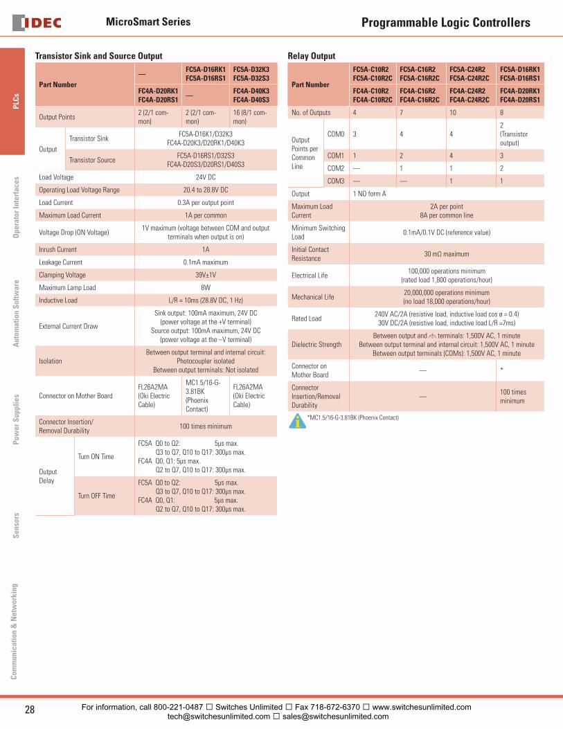
Transistor Sink and Source Output
Part Number
—FC5A-D16RK1FC5A-D16RS1
FC5A-D32K3FC5A-D32S3
FC4A-D20RK1FC4A-D20RS1
—FC4A-D40K3FC4A-D40S3
Output Points2 (2/1 com-mon)
2 (2/1 com-mon)
16 (8/1 com-mon)
Output
Transistor Sink FC5A-D16K1/D32K3
FC4A-D20K3/D20RK1/D40K3
Transistor SourceFC5A-D16RS1/D32S3
FC4A-D20S3/D20RS1/D40S3
Load Voltage 24V DC
Operating Load Voltage Range 20.4 to 28.8V DC
Load Current 0.3A per output point
Maximum Load Current 1A per common
Voltage Drop (ON Voltage)1V maximum (voltage between COM and output
terminals when output is on)
Inrush Current 1A
Leakage Current 0.1mA maximum
Clamping Voltage 39V±1V
Maximum Lamp Load 8W
Inductive Load L/R = 10ms (28.8V DC, 1 Hz)
External Current Draw
Sink output: 100mA maximum, 24V DC(power voltage at the +V terminal)
Source output: 100mA maximum, 24V DC(power voltage at the –V terminal)
IsolationBetween output terminal and internal circuit:
Photocoupler isolatedBetween output terminals: Not isolated
Connector on Mother BoardFL26A2MA(Oki Electric Cable)
MC1.5/16-G-3.81BK(Phoenix Contact)
FL26A2MA(Oki Electric Cable)
Connector Insertion/Removal Durability
100 times minimum
Output Delay
Turn ON Time
FC5A Q0 to Q2: 5μs max. Q3 to Q7, Q10 to Q17: 300μs max.FC4A Q0, Q1: 5μs max. Q2 to Q7, Q10 to Q17: 300μs max.
Turn OFF Time
FC5A Q0 to Q2: 5μs max. Q3 to Q7, Q10 to Q17: 300μs max.FC4A Q0, Q1: 5μs max. Q2 to Q7, Q10 to Q17: 300μs max.
Relay Output
Part Number
FC5A-C10R2FC5A-C10R2C
FC5A-C16R2FC5A-C16R2C
FC5A-C24R2FC5A-C24R2C
FC5A-D16RK1FC5A-D16RS1
FC4A-C10R2FC4A-C10R2C
FC4A-C16R2FC4A-C16R2C
FC4A-C24R2FC4A-C24R2C
FC4A-D20RK1FC4A-D20RS1
No. of Outputs 4 7 10 8
Output Points per Common Line
COM0 3 4 42(Transistor output)
COM1 1 2 4 3
COM2 — 1 1 2
COM3 — — 1 1
Output 1 NO form A
Maximum Load Current
2A per point8A per common line
Minimum Switching Load
0.1mA/0.1V DC (reference value)
Initial Contact Resistance
30 mΩ maximum
Electrical Life100,000 operations minimum
(rated load 1,800 operations/hour)
Mechanical Life20,000,000 operations minimum(no load 18,000 operations/hour)
Rated Load240V AC/2A (resistive load, inductive load cos ø = 0.4)
30V DC/2A (resistive load, inductive load L/R =7ms)
Dielectric Strength Between output and terminals: 1,500V AC, 1 minute
Between output terminal and internal circuit: 1,500V AC, 1 minuteBetween output terminals (COMs): 1,500V AC, 1 minute
Connector on Mother Board
— *
Connector Insertion/Removal Durability
—100 times minimum
*MC1.5/16-G-3.81BK (Phoenix Contact)
For information, call 800-221-0487 � Switches Unlimited � Fax 718-672-6370 � www.switchesunlimited.com [email protected] � [email protected]
MicroSmart Series
29USA: 800-262-IDEC Canada: 888-317-IDEC
PLC
sO
perator InterfacesA
utomation S
oftware
Pow
er Supplies
Sensors
Com
munication &
Netw
orking
Programmable Logic Controllers
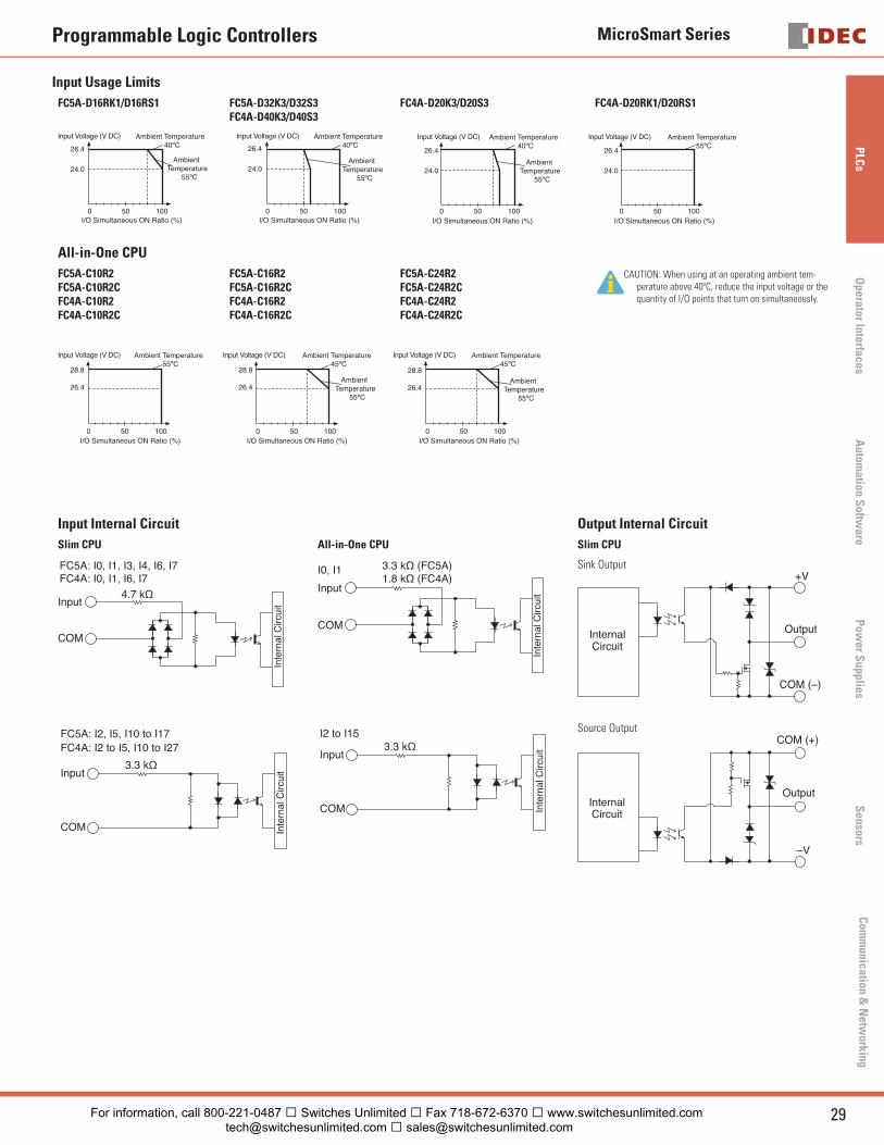
Input Usage Limits
FC5A-D16RK1/D16RS1 FC5A-D32K3/D32S3FC4A-D40K3/D40S3
FC4A-D20K3/D20S3 FC4A-D20RK1/D20RS1
Input Voltage (V DC)Input Voltage (V DC)Input Voltage (V DC) Input Voltage (V DC)Ambient Temperature 40ºC
Ambient Temperature 40ºC
Ambient Temperature 40ºC
Ambient Temperature
55ºC
Ambient Temperature
55ºC
Ambient Temperature
55ºC
Ambient Temperature 55ºC
I/O Simultaneous ON Ratio (%) I/O Simultaneous ON Ratio (%)I/O Simultaneous ON Ratio (%)
26.4
24.0
26.4
24.0
26.4
24.0
26.4
24.0
I/O Simultaneous ON Ratio (%)0 50 100 0 50 100 0 50 100 0 50 100
All-in-One CPU
FC5A-C10R2FC5A-C10R2CFC4A-C10R2FC4A-C10R2C
FC5A-C16R2FC5A-C16R2CFC4A-C16R2FC4A-C16R2C
FC5A-C24R2FC5A-C24R2CFC4A-C24R2FC4A-C24R2C
CAUTION: When using at an operating ambient tem-perature above 40ºC, reduce the input voltage or the quantity of I/O points that turn on simultaneously.
28.8
26.4
28.8
26.4
28.8
26.4
Input Voltage (V DC) Input Voltage (V DC) Input Voltage (V DC)Ambient Temperature 55ºC
Ambient Temperature 45ºC
Ambient Temperature 45ºC
Ambient Temperature
55ºC
Ambient Temperature
55ºC
I/O Simultaneous ON Ratio (%) I/O Simultaneous ON Ratio (%) I/O Simultaneous ON Ratio (%)0 50 100 0 50 100 0 50 100
Input Internal Circuit Output Internal Circuit
Slim CPU All-in-One CPU Slim CPU
4.7 kΩ
FC4A: I0, I1, I6, I7FC5A: I0, I1, I3, I4, I6, I7
COM
Input
Inte
rnal
Circ
uit
Input
3.3 kΩ (FC5A)1.8 kΩ (FC4A)
I0, I1
COM
Inte
rnal
Circ
uit
Sink Output
InternalCircuit
+V
Output
COM (–)
COM
Input3.3 kΩ
FC4A: I2 to I5, I10 to I27FC5A: I2, I5, I10 to I17
Inte
rnal
Circ
uit
COM
Input3.3 kΩ
I2 to I15
Inte
rnal
Circ
uit
Source Output
InternalCircuit
–V
Output
COM (+)
For information, call 800-221-0487 � Switches Unlimited � Fax 718-672-6370 � www.switchesunlimited.com [email protected] � [email protected]
MicroSmart Series
30 www.idec.com
PLC
sO
pera
tor
Inte
rfac
esA
utom
atio
n S
oftw
are
Pow
er S
uppl
ies
Sen
sors
Com
mun
icat
ion
& N
etw
orki
ng
Programmable Logic Controllers
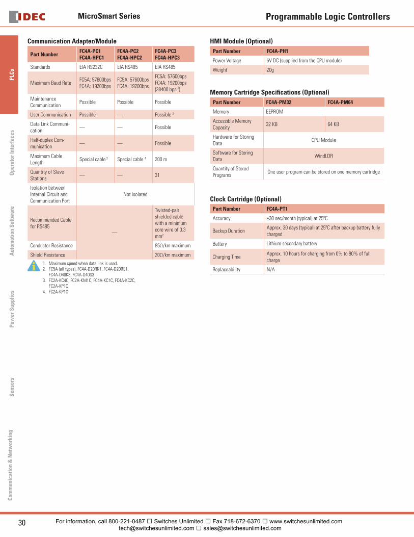
Communication Adapter/Module
Part NumberFC4A-PC1FC4A-HPC1
FC4A-PC2FC4A-HPC2
FC4A-PC3FC4A-HPC3
Standards EIA RS232C EIA RS485 EIA RS485
Maximum Baud RateFC5A: 57600bpsFC4A: 19200bps
FC5A: 57600bpsFC4A: 19200bps
FC5A: 57600bpsFC4A: 19200bps (38400 bps 1)
MaintenanceCommunication
Possible Possible Possible
User Communication Possible — Possible 2
Data Link Communi-cation
— — Possible
Half-duplex Com-munication
— — Possible
Maximum Cable Length
Special cable 3 Special cable 4 200 m
Quantity of Slave Stations
— — 31
Isolation between Internal Circuit and Communication Port
Not isolated
Recommended Cable for RS485
—
Twisted-pair shielded cable with a minimum core wire of 0.3 mm2
Conductor Resistance 85Ω/km maximum
Shield Resistance 20Ω/km maximum
1. Maximum speed when data link is used.2. FC5A (all types), FC4A-D20RK1, FC4A-D20RS1,
FC4A-D40K3, FC4A-D40S33. FC2A-KC4C, FC2A-KM1C, FC4A-KC1C, FC4A-KC2C,
FC2A-KP1C4. FC2A-KP1C
HMI Module (Optional)
Part Number FC4A-PH1
Power Voltage 5V DC (supplied from the CPU module)
Weight 20g
Memory Cartridge Specifi cations (Optional)
Part Number FC4A-PM32 FC4A-PM64
Memory EEPROM
Accessible MemoryCapacity
32 KB 64 KB
Hardware for Storing Data
CPU Module
Software for Storing Data
WindLDR
Quantity of Stored Programs
One user program can be stored on one memory cartridge
Clock Cartridge (Optional)
Part Number FC4A-PT1
Accuracy ±30 sec/month (typical) at 25ºC
Backup DurationApprox. 30 days (typical) at 25ºC after backup battery fully charged
Battery Lithium secondary battery
Charging TimeApprox. 10 hours for charging from 0% to 90% of full charge
Replaceability N/A
For information, call 800-221-0487 � Switches Unlimited � Fax 718-672-6370 � www.switchesunlimited.com [email protected] � [email protected]
MicroSmart Series
31USA: 800-262-IDEC Canada: 888-317-IDEC
PLC
sO
perator InterfacesA
utomation S
oftware
Pow
er Supplies
Sensors
Com
munication &
Netw
orking
Programmable Logic Controllers
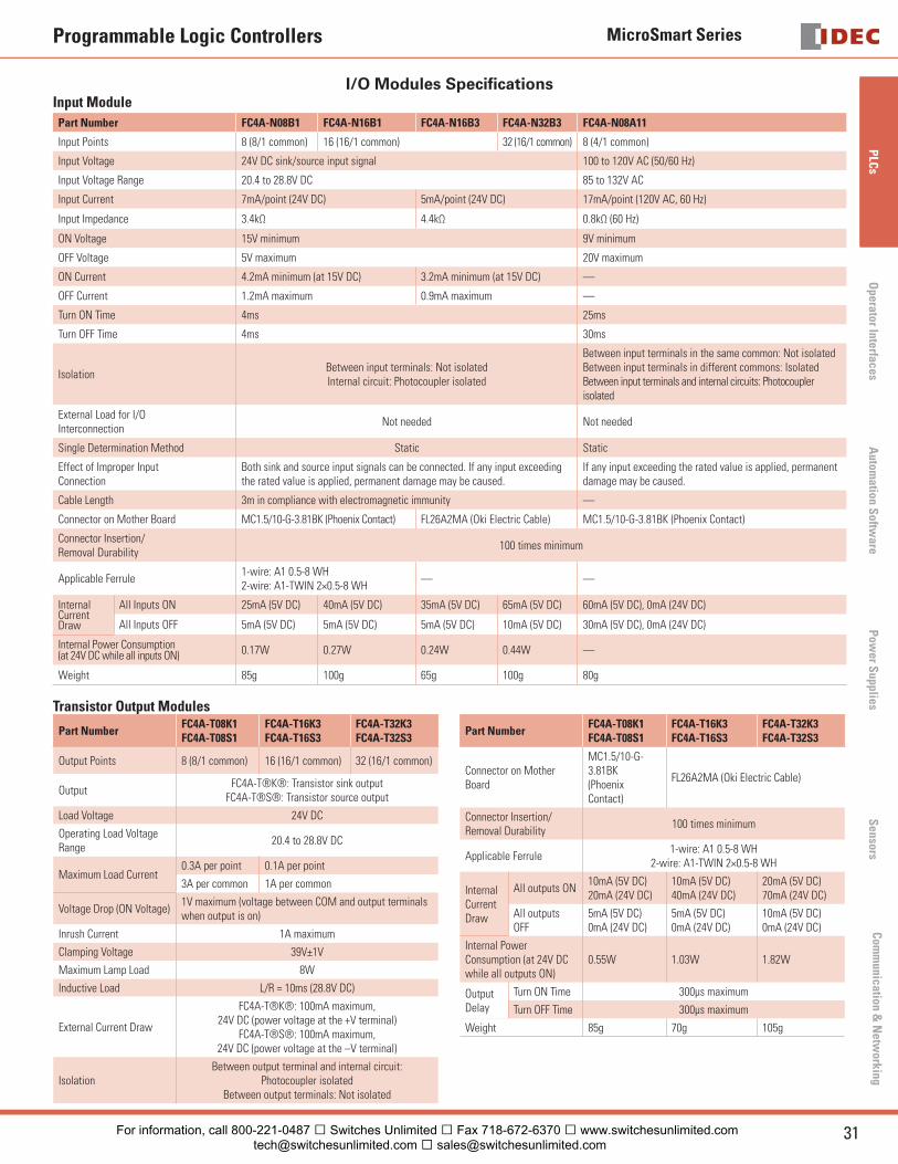
I/O Modules Specifi cationsInput Module
Part Number FC4A-N08B1 FC4A-N16B1 FC4A-N16B3 FC4A-N32B3 FC4A-N08A11
Input Points 8 (8/1 common) 16 (16/1 common) 32 (16/1 common) 8 (4/1 common)
Input Voltage 24V DC sink/source input signal 100 to 120V AC (50/60 Hz)
Input Voltage Range 20.4 to 28.8V DC 85 to 132V AC
Input Current 7mA/point (24V DC) 5mA/point (24V DC) 17mA/point (120V AC, 60 Hz)
Input Impedance 3.4kΩ 4.4kΩ 0.8kΩ (60 Hz)
ON Voltage 15V minimum 9V minimum
OFF Voltage 5V maximum 20V maximum
ON Current 4.2mA minimum (at 15V DC) 3.2mA minimum (at 15V DC) —
OFF Current 1.2mA maximum 0.9mA maximum —
Turn ON Time 4ms 25ms
Turn OFF Time 4ms 30ms
IsolationBetween input terminals: Not isolatedInternal circuit: Photocoupler isolated
Between input terminals in the same common: Not isolatedBetween input terminals in different commons: IsolatedBetween input terminals and internal circuits: Photocoupler isolated
External Load for I/O Interconnection
Not needed Not needed
Single Determination Method Static Static
Effect of Improper Input Connection
Both sink and source input signals can be connected. If any input exceeding the rated value is applied, permanent damage may be caused.
If any input exceeding the rated value is applied, permanent damage may be caused.
Cable Length 3m in compliance with electromagnetic immunity —
Connector on Mother Board MC1.5/10-G-3.81BK (Phoenix Contact) FL26A2MA (Oki Electric Cable) MC1.5/10-G-3.81BK (Phoenix Contact)
Connector Insertion/Removal Durability
100 times minimum
Applicable Ferrule1-wire: A1 0.5-8 WH2-wire: A1-TWIN 2×0.5-8 WH
— —
InternalCurrent Draw
All Inputs ON 25mA (5V DC) 40mA (5V DC) 35mA (5V DC) 65mA (5V DC) 60mA (5V DC), 0mA (24V DC)
All Inputs OFF 5mA (5V DC) 5mA (5V DC) 5mA (5V DC) 10mA (5V DC) 30mA (5V DC), 0mA (24V DC)
Internal Power Consumption(at 24V DC while all inputs ON) 0.17W 0.27W 0.24W 0.44W —
Weight 85g 100g 65g 100g 80g
Transistor Output Modules
Part NumberFC4A-T08K1FC4A-T08S1
FC4A-T16K3FC4A-T16S3
FC4A-T32K3FC4A-T32S3
Output Points 8 (8/1 common) 16 (16/1 common) 32 (16/1 common)
Output FC4A-T®K®: Transistor sink output
FC4A-T®S®: Transistor source output
Load Voltage 24V DC
Operating Load Voltage Range
20.4 to 28.8V DC
Maximum Load Current0.3A per point 0.1A per point
3A per common 1A per common
Voltage Drop (ON Voltage)1V maximum (voltage between COM and output terminals when output is on)
Inrush Current 1A maximum
Clamping Voltage 39V±1V
Maximum Lamp Load 8W
Inductive Load L/R = 10ms (28.8V DC)
External Current Draw
FC4A-T®K®: 100mA maximum, 24V DC (power voltage at the +V terminal)
FC4A-T®S®: 100mA maximum, 24V DC (power voltage at the –V terminal)
IsolationBetween output terminal and internal circuit:
Photocoupler isolatedBetween output terminals: Not isolated
Part NumberFC4A-T08K1FC4A-T08S1
FC4A-T16K3FC4A-T16S3
FC4A-T32K3FC4A-T32S3
Connector on Mother Board
MC1.5/10-G-3.81BK (Phoenix Contact)
FL26A2MA (Oki Electric Cable)
Connector Insertion/Removal Durability
100 times minimum
Applicable Ferrule1-wire: A1 0.5-8 WH
2-wire: A1-TWIN 2×0.5-8 WH
Internal Current Draw
All outputs ON10mA (5V DC)20mA (24V DC)
10mA (5V DC)40mA (24V DC)
20mA (5V DC)70mA (24V DC)
All outputs OFF
5mA (5V DC)0mA (24V DC)
5mA (5V DC)0mA (24V DC)
10mA (5V DC)0mA (24V DC)
Internal Power Consumption (at 24V DC while all outputs ON)
0.55W 1.03W 1.82W
Output Delay
Turn ON Time 300μs maximum
Turn OFF Time 300μs maximum
Weight 85g 70g 105g
For information, call 800-221-0487 � Switches Unlimited � Fax 718-672-6370 � www.switchesunlimited.com [email protected] � [email protected]

MicroSmart Series
32 www.idec.com
PLC
sO
pera
tor
Inte
rfac
esA
utom
atio
n S
oftw
are
Pow
er S
uppl
ies
Sen
sors
Com
mun
icat
ion
& N
etw
orki
ng
Programmable Logic Controllers
Relay Output Module Specifi cations
Part Number FC4A-R081 FC4A-R161
Output Points 8 (4/1 common) 16 (8/1 common)
Output 1NO (form A)
Maximum Load Current2A per point
7A per common 8A per common
Minimum Switching Load 0.1mA/0.1V DC (reference value)
Initial Contact Resistance 30mΩ maximum
Electrical Life100,000 operations minimum
(rated load 1,800 operations/hour)
Mechanical Life20,000,000 operations minimum(no load 1,8000 operations/hour)
Rated Load 240V AC/2A (resistive load, inductive load cos ø = 0.4)30V DC/2A (resistive load, inductive load L/R = 7ms)
Dielectric StrengthBetween output and or terminals: 1,500V AC 1 minute
Between output terminal and internal circuit: 1,500V AC, 1 minuteBetween output terminals (COMs): 1,500V AC, 1 minute
ConnectorOn Mother Board
MC1.5/11-G-3.81BK(Phoenix Contact)
MC1.5/10-G-3.81BK(Phoenix Contact)
Connector Insertion/Removal Durability
100 times minimum
Applicable Ferrule1-wire: A1 0.5-8 WH
2-wire: A1-TWIN 2×0.5-8 WH
InternalCurrent Draw
All outputs ON30mA (5V DC)40mA (24V DC)
45mA (5V DC)75mA (24V DC)
All outputs OFF5mA (5V DC)0mA (24V DC)
5mA (5V DC)0mA (24V DC)
Internal Power Consumption (at 24V DC while all outputs ON)
1.16W 2.10W
Weight 110g 145g
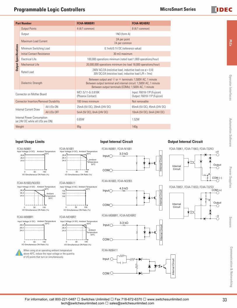
Combination I/O Module Specifi cations
Part Number FC4A-M08BR1 FC4A-M24BR2
Inpu
t Spe
cifi c
atio
ns
Input Points 4 (4/1 common) 16 (16/1 common)
Input Voltage 24V DC sink/source input signal
Input Voltage Range 20.4 to 28.8V DC
Input Current 7mA/point (24V DC)
Input Impedance 3.4kΩ
ON Voltage 15V minimum
OFF Voltage 5V maximum
ON Current 4.2mA minimum (at 15V DC)
OFF Current 1.2mA maximum
Turn ON Time 4ms (24V DC)
Turn OFF Time 4ms (24V DC)
IsolationBetween input terminals: Not isolatedInternal circuit: Photocoupler isolated
External Load for I/O Interconnection Not needed
Signal Determination Method Static
Effect of Improper Input ConnectionBoth sinking and sourcing input signals can be connected.
If any input exceeding the rated value is applied, permanent damage may be caused.
Cable Length 3m in compliance with electromagnetic immunity
For information, call 800-221-0487 � Switches Unlimited � Fax 718-672-6370 � www.switchesunlimited.com [email protected] � [email protected]
MicroSmart Series
33USA: 800-262-IDEC Canada: 888-317-IDEC
PLC
sO
perator InterfacesA
utomation S
oftware
Pow
er Supplies
Sensors
Com
munication &
Netw
orking
Programmable Logic Controllers
Part Number FC4A-M08BR1 FC4A-M24BR2
Out
put S
peci
fi cat
ions
Output Points 4 (4/1 common) 8 (4/1 common)
Output 1NO (form A)
Maximum Load Current2A per point
7A per common
Minimum Switching Load 0.1mA/0.1V DC (reference value)
Initial Contact Resistance 30 mΩ maximum
Electrical Life 100,000 operations minimum (rated load 1,800 operations/hour)
Mechanical Life 20,000,000 operations minimum (no load 18,000 operations/hour)
Rated Load240V AC/2A (resistive load, inductive load cos ø = 0.4)30V DC/2A (resistive load, inductive load L/R = 7ms)
Dielectric StrengthBetween output and or terminals: 1,500V AC, 1 minute
Between output terminal and internal circuit: 1,500V AC, 1 minuteBetween output terminals (COMs): 1,500V AC, 1 minute
Connector on Mother BoardMC1.5/11-G-3.81BK (Phoenix Contact)
Input: F6018-17P (Fujicon)Output: F6018-11P (Fujicon)
Connector Insertion/Removal Durability 100 times minimum Not removable
Internal Current DrawAll I/Os ON 25mA (5V DC), 20mA (24V DC) 65mA (5V DC), 45mA (24V DC)
All I/Os OFF 5mA (5V DC), 0mA (24V DC) 10mA (5V DC), 0mA (24V DC)
Internal Power Consumption(at 24V DC while all I/Os are ON)
0.65W 1.52W
Weight 95g 140g
Input Usage Limits Input Internal Circuit Output Internal Circuit
FC4A-N08B1
28.826.424.0
0 50 100
Input Voltage (V DC) Ambient Temperature 55ºC
I/O Simultaneous ON Ratio (%)
FC4A-N16B1
28.826.424.0
0 50 100
Input Voltage (V DC) Ambient Temperature 45ºC
AmbientTemperature
55ºC
I/O Simultaneous ON Ratio (%)
FC4A-N16B3/N32B3
28.826.424.0
0 50 100
Input Voltage (V DC)
AmbientTemperature
55ºC
Ambient Temperature 30ºC
I/O Simultaneous ON Ratio (%)
FC4A-N08A11
0 50 100I/O Simultaneous ON Ratio (%)
Ambient Temperature55ºC
Input Voltage (V AC)
132120102
FC4A-M08BR1
28.826.424.0
0 50 100
Input Voltage (V DC) Ambient Temperature 55ºC
I/O Simultaneous ON Ratio (%)
FC4A-M24BR2
28.826.424.0
0 50 100
Input Voltage (V DC)
AmbientTemperature
55ºC
Ambient Temperature 45ºC
I/O Simultaneous ON Ratio (%)
When using at an operating ambient temperature above 40ºC, reduce the input voltage or the quantity of I/O points that turn on simultaneously.
FC4A-N08B1, FC4A-N16B1
COM
Input3.3 kΩ
Inte
rnal
Circ
uit
FC4A-N16B3, FC4A-N32B3
COM
4.3 kΩ
Inte
rnal
Circ
uitInput
FC4A-M08BR1, FC4A-M24BR2
COM
3.3 kΩ
Inte
rnal
Circ
uitInput
FC4A-N08A11
COM
Input
Inte
rnal
Circ
uit
FC4A-T08K1, FC4A-T16K3, FC4A-T32K3+V
Output
COM (–)
InternalCircuit
FC4A-T08S1, FC4A-T16S3, FC4A-T32S3
–V
Output
COM (+)
InternalCircuit
For information, call 800-221-0487 � Switches Unlimited � Fax 718-672-6370 � www.switchesunlimited.com [email protected] � [email protected]
MicroSmart Series
34 www.idec.com
PLC
sO
pera
tor
Inte
rfac
esA
utom
atio
n S
oftw
are
Pow
er S
uppl
ies
Sen
sors
Com
mun
icat
ion
& N
etw
orki
ng
Programmable Logic Controllers
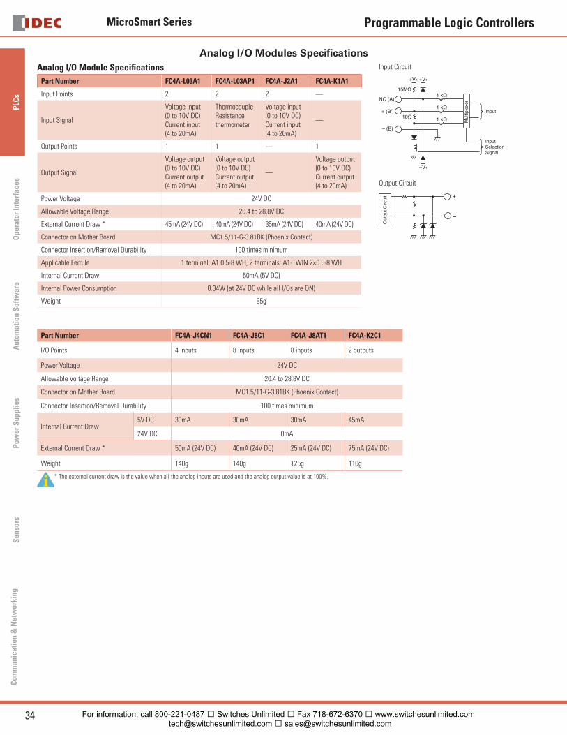
Analog I/O Modules Specifi cationsAnalog I/O Module Specifi cations
Part Number FC4A-L03A1 FC4A-L03AP1 FC4A-J2A1 FC4A-K1A1
Input Points 2 2 2 —
Input Signal
Voltage input(0 to 10V DC)Current input(4 to 20mA)
ThermocoupleResistancethermometer
Voltage input(0 to 10V DC)Current input(4 to 20mA)
—
Output Points 1 1 — 1
Output Signal
Voltage output(0 to 10V DC)Current output(4 to 20mA)
Voltage output(0 to 10V DC)Current output(4 to 20mA)
—
Voltage output(0 to 10V DC)Current output(4 to 20mA)
Power Voltage 24V DC
Allowable Voltage Range 20.4 to 28.8V DC
External Current Draw * 45mA (24V DC) 40mA (24V DC) 35mA (24V DC) 40mA (24V DC)
Connector on Mother Board MC1.5/11-G-3.81BK (Phoenix Contact)
Connector Insertion/Removal Durability 100 times minimum
Applicable Ferrule 1 terminal: A1 0.5-8 WH, 2 terminals: A1-TWIN 2×0.5-8 WH
Internal Current Draw 50mA (5V DC)
Internal Power Consumption 0.34W (at 24V DC while all I/Os are ON)
Weight 85g
Input Circuit
NC (A)1 kΩ
15MΩ
+ (B’)
– (B)
1 kΩ
1 kΩ10Ω
+V2 +V1
–V1
InputSelectionSignal
Input
Mul
tiple
xer
Output Circuit
−
Out
put C
ircui
t +
Part Number FC4A-J4CN1 FC4A-J8C1 FC4A-J8AT1 FC4A-K2C1
I/O Points 4 inputs 8 inputs 8 inputs 2 outputs
Power Voltage 24V DC
Allowable Voltage Range 20.4 to 28.8V DC
Connector on Mother Board MC1.5/11-G-3.81BK (Phoenix Contact)
Connector Insertion/Removal Durability 100 times minimum
Internal Current Draw5V DC 30mA 30mA 30mA 45mA
24V DC 0mA
External Current Draw * 50mA (24V DC) 40mA (24V DC) 25mA (24V DC) 75mA (24V DC)
Weight 140g 140g 125g 110g
* The external current draw is the value when all the analog inputs are used and the analog output value is at 100%.
For information, call 800-221-0487 � Switches Unlimited � Fax 718-672-6370 � www.switchesunlimited.com [email protected] � [email protected]
MicroSmart Series
35USA: 800-262-IDEC Canada: 888-317-IDEC
PLC
sO
perator InterfacesA
utomation S
oftware
Pow
er Supplies
Sensors
Com
munication &
Netw
orking
Programmable Logic Controllers
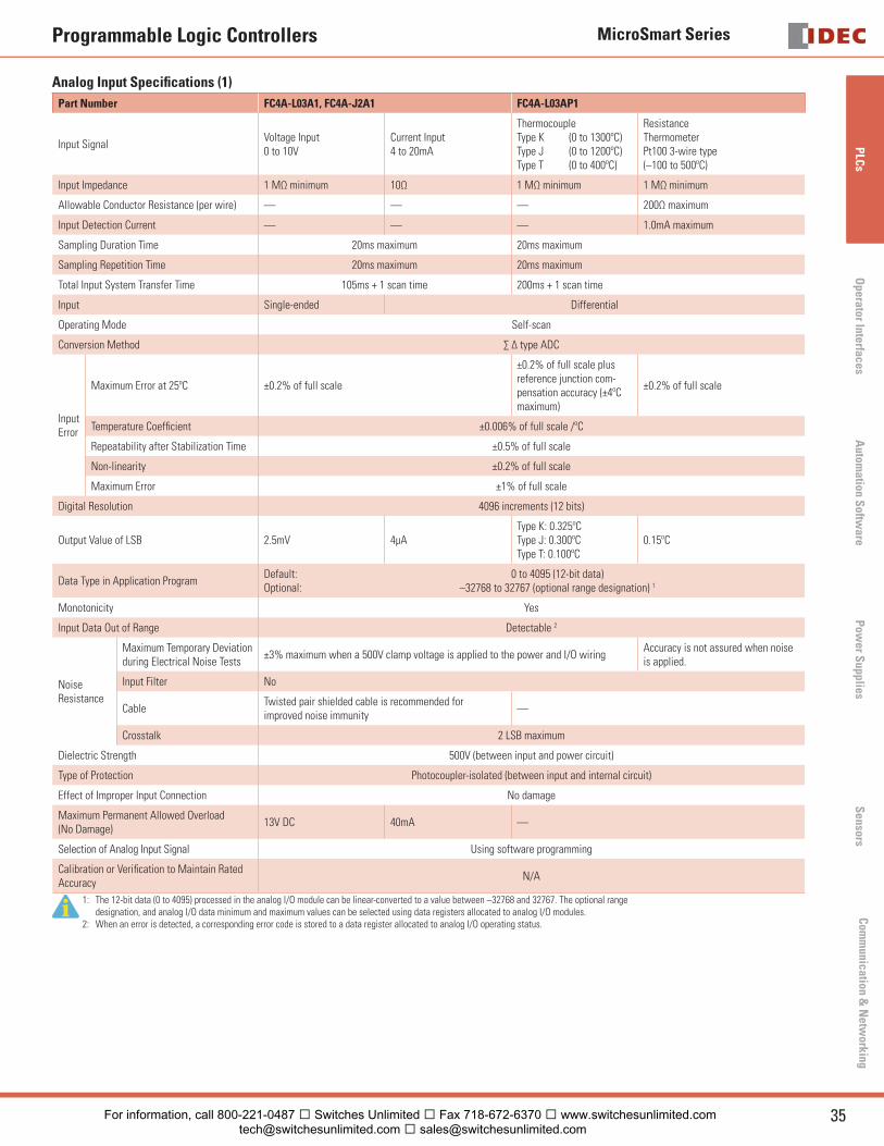
Analog Input Specifi cations (1)
Part Number FC4A-L03A1, FC4A-J2A1 FC4A-L03AP1
Input Signal Voltage Input0 to 10V
Current Input4 to 20mA
ThermocoupleType K (0 to 1300ºC)Type J (0 to 1200ºC)Type T (0 to 400ºC)
ResistanceThermometerPt100 3-wire type(–100 to 500ºC)
Input Impedance 1 MΩ minimum 10Ω 1 MΩ minimum 1 MΩ minimum
Allowable Conductor Resistance (per wire) — — — 200Ω maximum
Input Detection Current — — — 1.0mA maximum
Sampling Duration Time 20ms maximum 20ms maximum
Sampling Repetition Time 20ms maximum 20ms maximum
Total Input System Transfer Time 105ms + 1 scan time 200ms + 1 scan time
Input Single-ended Differential
Operating Mode Self-scan
Conversion Method ∑ Δ type ADC
InputError
Maximum Error at 25ºC ±0.2% of full scale
±0.2% of full scale plus reference junction com-pensation accuracy (±4ºC maximum)
±0.2% of full scale
Temperature Coeffi cient ±0.006% of full scale /ºC
Repeatability after Stabilization Time ±0.5% of full scale
Non-linearity ±0.2% of full scale
Maximum Error ±1% of full scale
Digital Resolution 4096 increments (12 bits)
Output Value of LSB 2.5mV 4μAType K: 0.325ºCType J: 0.300ºCType T: 0.100ºC
0.15ºC
Data Type in Application ProgramDefault: 0 to 4095 (12-bit data)Optional: –32768 to 32767 (optional range designation) 1
Monotonicity Yes
Input Data Out of Range Detectable 2
NoiseResistance
Maximum Temporary Deviation during Electrical Noise Tests
±3% maximum when a 500V clamp voltage is applied to the power and I/O wiringAccuracy is not assured when noise is applied.
Input Filter No
CableTwisted pair shielded cable is recommended forimproved noise immunity
—
Crosstalk 2 LSB maximum
Dielectric Strength 500V (between input and power circuit)
Type of Protection Photocoupler-isolated (between input and internal circuit)
Effect of Improper Input Connection No damage
Maximum Permanent Allowed Overload(No Damage)
13V DC 40mA —
Selection of Analog Input Signal Using software programming
Calibration or Verifi cation to Maintain Rated Accuracy
N/A
1: The 12-bit data (0 to 4095) processed in the analog I/O module can be linear-converted to a value between –32768 and 32767. The optional range designation, and analog I/O data minimum and maximum values can be selected using data registers allocated to analog I/O modules.
2: When an error is detected, a corresponding error code is stored to a data register allocated to analog I/O operating status.
For information, call 800-221-0487 � Switches Unlimited � Fax 718-672-6370 � www.switchesunlimited.com [email protected] � [email protected]
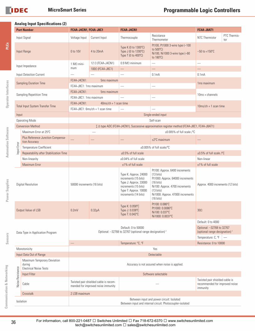
MicroSmart Series
36 www.idec.com
PLC
sO
pera
tor
Inte
rfac
esA
utom
atio
n S
oftw
are
Pow
er S
uppl
ies
Sen
sors
Com
mun
icat
ion
& N
etw
orki
ng
Programmable Logic Controllers
Analog Input Specifi cations (2)
Part Number FC4A-J4CN1, FC4A-J8C1 FC4A-J4CN1 FC4A-J8AT1
Input Signal Voltage Input Current Input ThermocoupleResistanceThermometer
NTC ThermistorPTC Thermis-tor
Input Range 0 to 10V 4 to 20mAType K (0 to 1300ºC)Type J (0 to 1200ºC)Type T (0 to 400ºC)
Pt100, Pt1000 3-wire type (–100 to 500ºC)Ni100, Ni1000 3-wire type (–60 to 180ºC)
–50 to +150ºC
Input Impedance1 MΩ mini-mum
12 Ω (FC4A-J4CN1) 0.9 MΩ minimum — —
100Ω (FC4A-J8C1) — — —
Input Detection Current — — — 0.1mA 0.1mA
Sampling Duration TimeFC4A-J4CN1: 5ms maximum
1ms maximumFC4A-J8C1: 1ms maximum — —
Sampling Repetition TimeFC4A-J4CN1: 5ms maximum
10ms × channelsFC4A-J8C1: 1ms maximum — —
Total Input System Transfer TimeFC4A-J4CN1: 40ms/ch + 1 scan time
10ms/ch + 1 scan timeFC4A-J8C1: 6ms/ch + 1 scan time — —
Input Single-ended input
Operating Mode Self-scan
Conversion Method ∑ Δ type ADC (FC4A-J4CN1), Successive approximation register method (FC4A-J8C1, FC4A-J8AT1)
Inpu
t Err
or
Maximum Error at 25ºC — ±0.005% of full scale /ºC
Plus Reference Junction Compensa-tion Accuracy
— — — ±2ºC maximum —
Temperature Coeffi cient ±0.005% of full scale/ºC
Repeatability after Stabilization Time ±0.5% of full scale ±0.5% of full scale /ºC
Non-linearity ±0.04% of full scale Non-linear
Maximum Error ±1% of full scale ±1% of full scale
Digital Resolution 50000 increments (16 bits)
Type K: Approx. 24000 increments (15 bits)Type J: Approx. 33000 increments (15 bits)Type T: Approx. 10000increments (14 bits)
Pt100: Approx. 6400 increments (13 bits)Pt1000: Approx. 64000 increments (16 bits)Ni100: Approx. 4700 increments (13 bits)Ni1000: Approx. 47000 increments (16 bits)
Approx. 4000 increments (12 bits)
Output Value of LSB 0.2mV 0.32μAType K: 0.058ºCType J: 0.038ºCType T: 0.042ºC
Pt100: 0.086ºCPt1000: 0.0086ºCNi100: 0.037ºCNi1000: 0.0037ºC
30Ω
Data Type in Application Program
Default: 0 to 50000Optional: –32768 to 32767 (optional range designation) 2
Default: 0 to 4000
Optional: –32768 to 32767 (optional range designation) 1
Temperature: C, ºF —
— Temperature: ºC, ºF Resistance: 0 to 10000
Monotonicity Yes
Input Data Out of Range Detectable
Noi
se R
esis
tanc
e
Maximum Temporary Deviation during Electrical Noise Tests
Accuracy is not assured when noise is applied.
Input Filter Software selectable
CableTwisted pair shielded cable is recom-mended for improved noise immunity
—Twisted pair shielded cable is recommended for improved noise immunity
Crosstalk 2 LSB maximum
IsolationBetween input and power circuit: Isolated
Between input and internal circuit: Photocoupler-isolated
For information, call 800-221-0487 � Switches Unlimited � Fax 718-672-6370 � www.switchesunlimited.com [email protected] � [email protected]
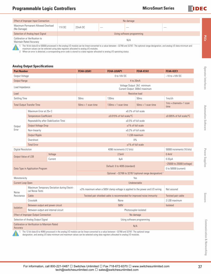
MicroSmart Series
37USA: 800-262-IDEC Canada: 888-317-IDEC
PLC
sO
perator InterfacesA
utomation S
oftware
Pow
er Supplies
Sensors
Com
munication &
Netw
orking
Programmable Logic Controllers
Effect of Improper Input Connection No damage
Maximum Permanent Allowed Overload (No Damage)
11V DC 22mA DC — — —
Selection of Analog Input Signal Using software programming
Calibration or Verifi cation toMaintain Rated Accuracy
N/A
1: The 16-bit data (0 to 50000) processed in the analog I/O module can be linear-converted to a value between –32768 and 32767. The optional range designation, and analog I/O data minimum and maximum values can be selected using data registers allocated to analog I/O modules.
2: When an error is detected, a corresponding error code is stored to a data register allocated to analog I/O operating status.
Analog Output Specifi cations
Part Number FC4A-L03A1 FC4A-L03AP1 FC4A-K1A1 FC4A-K2C1
Output Voltage 0 to 10V DC –10 to +10V DC
Output Range 4 to 20mA
Load ImpedanceVoltage Output: 2kΩ minimum
Current Output: 300kΩ maximum
Load Resistive load
Settling Time 50ms 130ms 50ms 1ms/ch
Total Output Transfer Time 50ms + 1 scan time 130ms + 1 scan time 50ms + 1 scan time1ms × channels+ 1 scan time
Output Error
Maximum Error at 25× C ±0.2% of full scale
Temperature Coeffi cient ±0.015% of full scale/ºC ±0.005% of full scale/ºC
Repeatability after Stabilization Time ±0.5% of full scale
Output Voltage Drop ±1% of full scale
Non-linearity ±0.2% of full scale
Output Ripple 1 LSB maximum
Overshoot 0%
Total Error ±1% of full scale
Digital Resolution 4096 increments (12 bits) 50000 increments (16 bits)
Output Value of LSBVoltage 2.5mV 0.4mV
Current 4μA 0.32μA
Data Type in Application ProgramDefault: 0 to 4095 (standard)
–25000 to 25000 (voltage)
0 to 50000 (current)
Optional: –32768 to 32767 (optional range designation) 1
Monotonicity Yes
Current Loop Open Undetectable
NoiseResistance
Maximum Temporary Deviation during Electri-cal Noise Tests
±3% maximum when a 500V clamp voltage is applied to the power and I/O wiring Not assured
Cable Twisted pair shielded cable is recommended for improved noise immunity Twisted pair cable
Crosstalk None 2 LSB maximum
IsolationBetween output and power circuit 500V Isolated
Between output and internal circuit Photocoupler-isolated
Effect of Improper Output Connection No damage
Selection of Analog Output Signal Using software programming
Calibration or Verifi cation to Maintain RatedAccuracy
N/A
1. The 12-bit data (0 to 4095) processed in the analog I/O module can be linear-converted to a value between –32768 and 32767. The optional range designation, and analog I/O data minimum and maximum values can be selected using data registers allocated to analog I/O modules.
For information, call 800-221-0487 � Switches Unlimited � Fax 718-672-6370 � www.switchesunlimited.com [email protected] � [email protected]
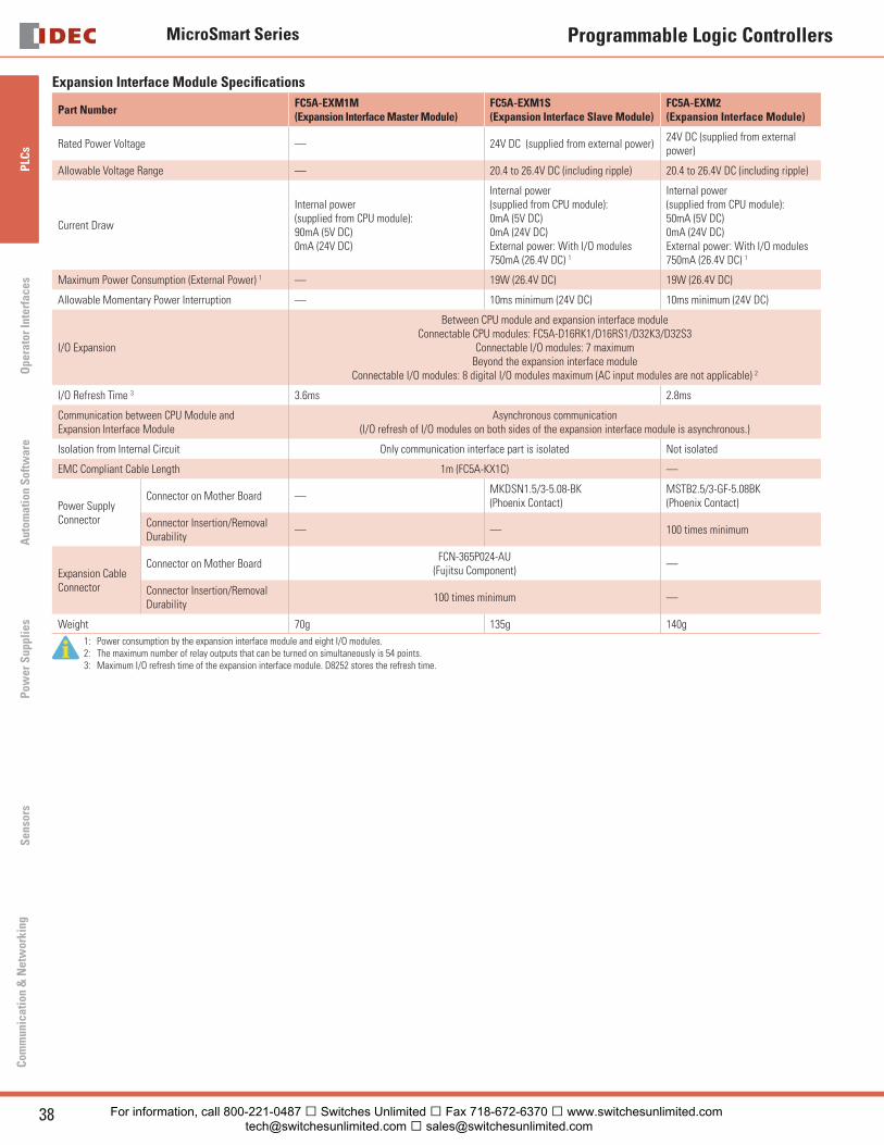
MicroSmart Series
38 www.idec.com
PLC
sO
pera
tor
Inte
rfac
esA
utom
atio
n S
oftw
are
Pow
er S
uppl
ies
Sen
sors
Com
mun
icat
ion
& N
etw
orki
ng
Programmable Logic Controllers
Expansion Interface Module Specifi cations
Part NumberFC5A-EXM1M (Expansion Interface Master Module)
FC5A-EXM1S(Expansion Interface Slave Module)
FC5A-EXM2(Expansion Interface Module)
Rated Power Voltage — 24V DC (supplied from external power)24V DC (supplied from external power)
Allowable Voltage Range — 20.4 to 26.4V DC (including ripple) 20.4 to 26.4V DC (including ripple)
Current Draw
Internal power(supplied from CPU module):90mA (5V DC)0mA (24V DC)
Internal power(supplied from CPU module):0mA (5V DC)0mA (24V DC)External power: With I/O modules 750mA (26.4V DC) 1
Internal power (supplied from CPU module):50mA (5V DC)0mA (24V DC)External power: With I/O modules750mA (26.4V DC) 1
Maximum Power Consumption (External Power) 1 — 19W (26.4V DC) 19W (26.4V DC)
Allowable Momentary Power Interruption — 10ms minimum (24V DC) 10ms minimum (24V DC)
I/O Expansion
Between CPU module and expansion interface moduleConnectable CPU modules: FC5A-D16RK1/D16RS1/D32K3/D32S3
Connectable I/O modules: 7 maximumBeyond the expansion interface module
Connectable I/O modules: 8 digital I/O modules maximum (AC input modules are not applicable) 2
I/O Refresh Time 3 3.6ms 2.8ms
Communication between CPU Module and Expansion Interface Module
Asynchronous communication(I/O refresh of I/O modules on both sides of the expansion interface module is asynchronous.)
Isolation from Internal Circuit Only communication interface part is isolated Not isolated
EMC Compliant Cable Length 1m (FC5A-KX1C) —
Power Supply Connector
Connector on Mother Board —MKDSN1.5/3-5.08-BK(Phoenix Contact)
MSTB2.5/3-GF-5.08BK(Phoenix Contact)
Connector Insertion/Removal Durability
— — 100 times minimum
Expansion Cable Connector
Connector on Mother Board FCN-365P024-AU
(Fujitsu Component)—
Connector Insertion/Removal Durability
100 times minimum —
Weight 70g 135g 140g
1: Power consumption by the expansion interface module and eight I/O modules.2: The maximum number of relay outputs that can be turned on simultaneously is 54 points.3: Maximum I/O refresh time of the expansion interface module. D8252 stores the refresh time.
For information, call 800-221-0487 � Switches Unlimited � Fax 718-672-6370 � www.switchesunlimited.com [email protected] � [email protected]
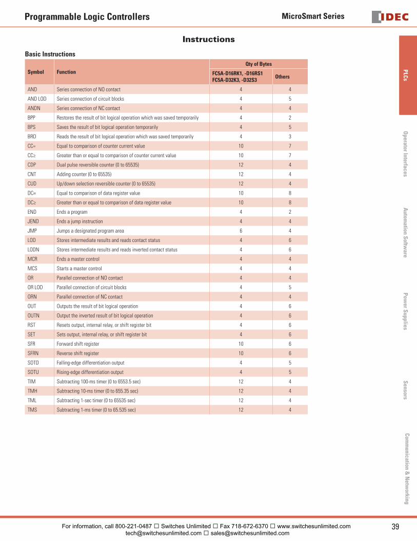
MicroSmart Series
39USA: 800-262-IDEC Canada: 888-317-IDEC
PLC
sO
perator InterfacesA
utomation S
oftware
Pow
er Supplies
Sensors
Com
munication &
Netw
orking
Programmable Logic Controllers
Instructions
Basic Instructions
Symbol Function
Qty of Bytes
FC5A-D16RK1, -D16RS1FC5A-D32K3, -D32S3
Others
AND Series connection of NO contact 4 4
AND LOD Series connection of circuit blocks 4 5
ANDN Series connection of NC contact 4 4
BPP Restores the result of bit logical operation which was saved temporarily 4 2
BPS Saves the result of bit logical operation temporarily 4 5
BRD Reads the result of bit logical operation which was saved temporarily 4 3
CC= Equal to comparison of counter current value 10 7
CC≥ Greater than or equal to comparison of counter current value 10 7
CDP Dual pulse reversible counter (0 to 65535) 12 4
CNT Adding counter (0 to 65535) 12 4
CUD Up/down selection reversible counter (0 to 65535) 12 4
DC= Equal to comparison of data register value 10 8
DC≥ Greater than or equal to comparison of data register value 10 8
END Ends a program 4 2
JEND Ends a jump instruction 4 4
JMP Jumps a designated program area 6 4
LOD Stores intermediate results and reads contact status 4 6
LODN Stores intermediate results and reads inverted contact status 4 6
MCR Ends a master control 4 4
MCS Starts a master control 4 4
OR Parallel connection of NO contact 4 4
OR LOD Parallel connection of circuit blocks 4 5
ORN Parallel connection of NC contact 4 4
OUT Outputs the result of bit logical operation 4 6
OUTN Output the inverted result of bit logical operation 4 6
RST Resets output, internal relay, or shift register bit 4 6
SET Sets output, internal relay, or shift register bit 4 6
SFR Forward shift register 10 6
SFRN Reverse shift register 10 6
SOTD Falling-edge differentiation output 4 5
SOTU Rising-edge differentiation output 4 5
TIM Subtracting 100-ms timer (0 to 6553.5 sec) 12 4
TMH Subtracting 10-ms timer (0 to 655.35 sec) 12 4
TML Subtracting 1-sec timer (0 to 65535 sec) 12 4
TMS Subtracting 1-ms timer (0 to 65.535 sec) 12 4
For information, call 800-221-0487 � Switches Unlimited � Fax 718-672-6370 � www.switchesunlimited.com [email protected] � [email protected]

MicroSmart Series
40 www.idec.com
PLC
sO
pera
tor
Inte
rfac
esA
utom
atio
n S
oftw
are
Pow
er S
uppl
ies
Sen
sors
Com
mun
icat
ion
& N
etw
orki
ng
Programmable Logic Controllers
Advanced Instructions
Symbol Function
Slim All-in-One
—FC5A-D16RK1, -D16RS1, -D32K3, -D32S3
FC5A-C10R2, C10R2C
FC5A-C16R2, C16R2C
FC5A-C24R2, C24R2C
FC4A-D20K3, -D20S3
FC4A-D20RK1, -D20RS1, -D40K3, -D40S3
FC4A-C10R2, -C10R2C
FC4A-C16R2, -C16R2C
FC4A-C24R2, -C24R2C
NOP No Operation × × × × ×
MOV Move × × × × ×
MOVN Move Not × × × × ×
IMOV Indirect Move × × × × ×
IMOVN Indirect Move Not × × × × ×
BMOV Block Move — × * * *
IBMV Indirect Bit Move — × * * *
IBMVN Indirect Bit Move Not — × * * *
CMP= Compare Equal To × × × × ×
CMP< > Compare Unequal To × × × × ×
CMP< Compare Less Than × × × × ×
CMP > Compare Greater Than × × × × ×
CMP < = Compare Less Than or Equal To × × × × ×
CMP > = Compare Greater Than or Equal To × × × × ×
ICMP > =Interval Compare Greater Than or Equal to
— × * * *
ADD Addition × × × × ×
SUB Subtraction × × × × ×
MUL Multiplication × × × × ×
DIV Division × × × × ×
ROOT Root × × × × ×
ANDW AND Word × × × × ×
ORW OR Word × × × × ×
XORW Exclusive OR Word × × × × ×
SFTL Shift Left × × × × ×
SFTR Shift Right × × × × ×
BCDLS• BCD Left Shift• – × * * *
WSFT Word Shift — × * * *
ROTL Rotate Left × × × × ×
ROTR Rotate Right × × × × ×
HTOB Hex to BCD × × × × ×
BTOH BCD to Hex × × × × ×
HTOA Hex to ASCII × × × × ×
ATOH ASCII to Hex × × × × ×
BTOA BCD to ASCII × × × × ×
ATOB ASCII to BCD × × × × ×
ENCO Encode — × * * *
DECO Decode — × * * *
BCNT Bit Count — × * * *
ALT Alternate Output — × * * *
CVDT Convert Data Type — * * * *
WKTIM Week Timer × × × × ×
WKTBL Week Table × × × × ×
DISP Display × × — — *
DGRD Digital Read × × — — *
TXD1 Transmit 1 × × × × ×
TXD2 Transmit 2 × × * × ×
RXD1 Receive 1 × × × × ×
For information, call 800-221-0487 � Switches Unlimited � Fax 718-672-6370 � www.switchesunlimited.com [email protected] � [email protected]
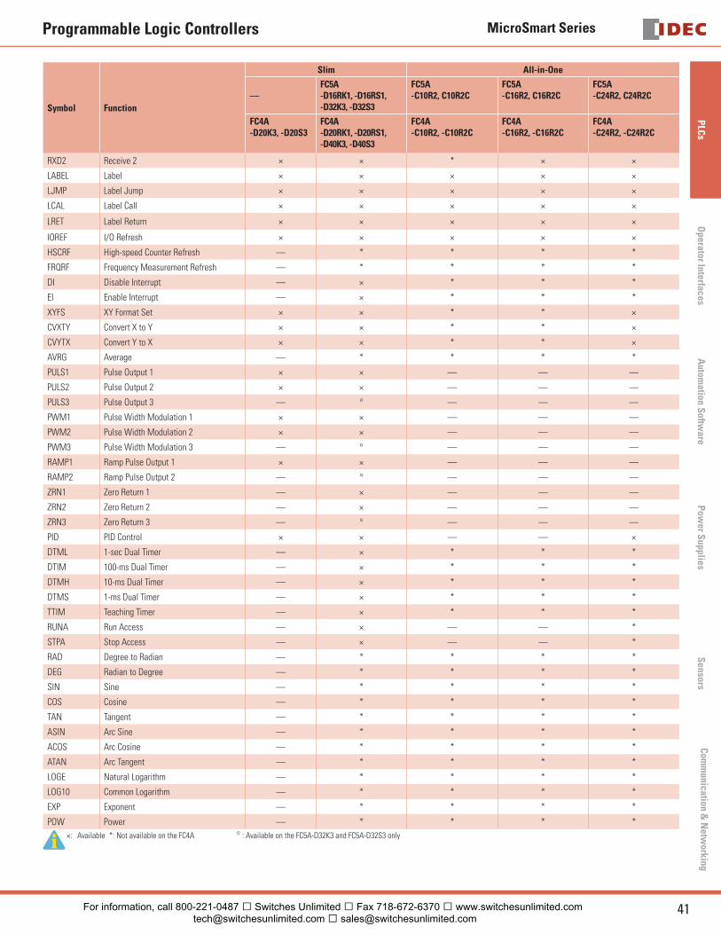
MicroSmart Series
41USA: 800-262-IDEC Canada: 888-317-IDEC
PLC
sO
perator InterfacesA
utomation S
oftware
Pow
er Supplies
Sensors
Com
munication &
Netw
orking
Programmable Logic Controllers
Symbol Function
Slim All-in-One
—FC5A-D16RK1, -D16RS1, -D32K3, -D32S3
FC5A-C10R2, C10R2C
FC5A-C16R2, C16R2C
FC5A-C24R2, C24R2C
FC4A-D20K3, -D20S3
FC4A-D20RK1, -D20RS1, -D40K3, -D40S3
FC4A-C10R2, -C10R2C
FC4A-C16R2, -C16R2C
FC4A-C24R2, -C24R2C
RXD2 Receive 2 × × * × ×
LABEL Label × × × × ×
LJMP Label Jump × × × × ×
LCAL Label Call × × × × ×
LRET Label Return × × × × ×
IOREF I/O Refresh × × × × ×
HSCRF High-speed Counter Refresh — * * * *
FRQRF Frequency Measurement Refresh — * * * *
DI Disable Interrupt — × * * *
EI Enable Interrupt — × * * *
XYFS XY Format Set × × * * ×
CVXTY Convert X to Y × × * * ×
CVYTX Convert Y to X × × * * ×
AVRG Average — * * * *
PULS1 Pulse Output 1 × × — — —
PULS2 Pulse Output 2 × × — — —
PULS3 Pulse Output 3 — ° — — —
PWM1 Pulse Width Modulation 1 × × — — —
PWM2 Pulse Width Modulation 2 × × — — —
PWM3 Pulse Width Modulation 3 — ° — — —
RAMP1 Ramp Pulse Output 1 × × — — —
RAMP2 Ramp Pulse Output 2 — ° — — —
ZRN1 Zero Return 1 — × — — —
ZRN2 Zero Return 2 — × — — —
ZRN3 Zero Return 3 — ° — — —
PID PID Control × × — — ×
DTML 1-sec Dual Timer — × * * *
DTIM 100-ms Dual Timer — × * * *
DTMH 10-ms Dual Timer — × * * *
DTMS 1-ms Dual Timer — × * * *
TTIM Teaching Timer — × * * *
RUNA Run Access — × — — *
STPA Stop Access — × — — *
RAD Degree to Radian — * * * *
DEG Radian to Degree — * * * *
SIN Sine — * * * *
COS Cosine — * * * *
TAN Tangent — * * * *
ASIN Arc Sine — * * * *
ACOS Arc Cosine — * * * *
ATAN Arc Tangent — * * * *
LOGE Natural Logarithm — * * * *
LOG10 Common Logarithm — * * * *
EXP Exponent — * * * *
POW Power — * * * *
×: Available *: Not available on the FC4A ° : Available on the FC5A-D32K3 and FC5A-D32S3 only
For information, call 800-221-0487 � Switches Unlimited � Fax 718-672-6370 � www.switchesunlimited.com [email protected] � [email protected]
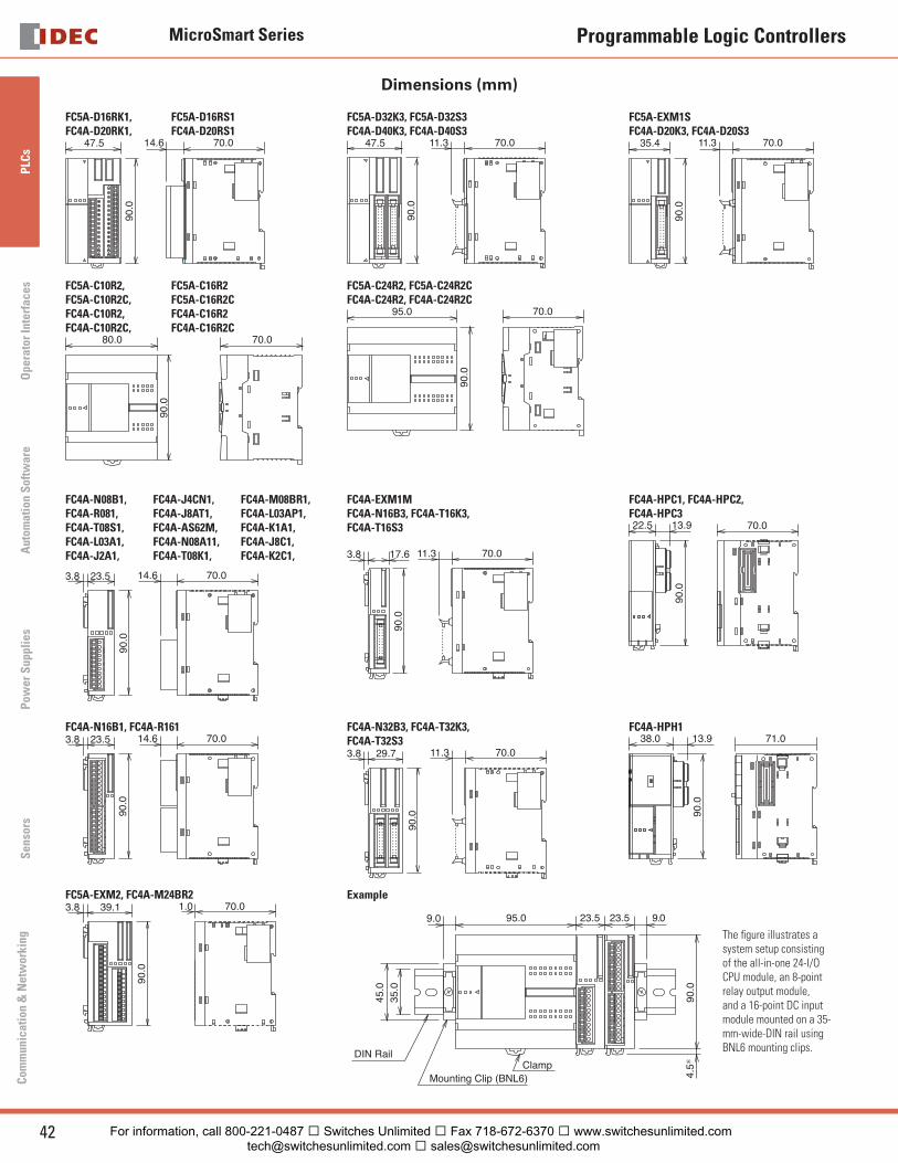
MicroSmart Series
42 www.idec.com
PLC
sO
pera
tor
Inte
rfac
esA
utom
atio
n S
oftw
are
Pow
er S
uppl
ies
Sen
sors
Com
mun
icat
ion
& N
etw
orki
ng
Programmable Logic Controllers
Dimensions (mm)
FC5A-D16RK1, FC5A-D16RS1FC4A-D20RK1, FC4A-D20RS1
47.590
.070.014.6
FC5A-D32K3, FC5A-D32S3FC4A-D40K3, FC4A-D40S3
47.5
90.0
70.011.3
FC5A-EXM1SFC4A-D20K3, FC4A-D20S3
35.4
90.0
70.011.3
FC5A-C10R2, FC5A-C16R2FC5A-C10R2C, FC5A-C16R2CFC4A-C10R2, FC4A-C16R2FC4A-C10R2C, FC4A-C16R2C
90.0
80.0 70.0
FC5A-C24R2, FC5A-C24R2CFC4A-C24R2, FC4A-C24R2C
95.0
90.0
70.0
FC4A-N08B1, FC4A-R081,FC4A-T08S1,FC4A-L03A1,FC4A-J2A1,
FC4A-J4CN1,FC4A-J8AT1,FC4A-AS62M,FC4A-N08A11, FC4A-T08K1,
FC4A-M08BR1,FC4A-L03AP1,FC4A-K1A1,FC4A-J8C1,FC4A-K2C1,
70.014.623.53.8
90.0
FC4A-EXM1MFC4A-N16B3, FC4A-T16K3,FC4A-T16S3
70.011.317.63.8
90.0
FC4A-HPC1, FC4A-HPC2,FC4A-HPC3
70.0
90.0
22.5 13.9
FC4A-N16B1, FC4A-R16170.014.623.53.8
90.0
FC4A-N32B3, FC4A-T32K3,FC4A-T32S3
70.011.329.73.8
90.0
FC4A-HPH171.0
90.0
38.0 13.9
FC5A-EXM2, FC4A-M24BR270.01.039.13.8
90.0
Example
95.0
DIN Rail
Mounting Clip (BNL6)
23.5 23.5 9.09.0
90.0
45.0
35.0
Clamp
4.5∗
The fi gure illustrates a system setup consisting of the all-in-one 24-I/O CPU module, an 8-point relay output module, and a 16-point DC input module mounted on a 35-mm-wide-DIN rail using BNL6 mounting clips.
For information, call 800-221-0487 � Switches Unlimited � Fax 718-672-6370 � www.switchesunlimited.com [email protected] � [email protected]
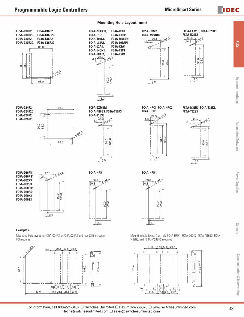
MicroSmart Series
43USA: 800-262-IDEC Canada: 888-317-IDEC
PLC
sO
perator InterfacesA
utomation S
oftware
Pow
er Supplies
Sensors
Com
munication &
Netw
orking
Programmable Logic Controllers
Mounting Hole Layout (mm)
FC5A-C10R2, FC5A-C16R2FC5A-C10R2C, FC5A-C16R2CFC4A-C10R2, FC4A-C16R2FC4A-C10R2C, FC4A-C16R2C
90.0
83.0
68.0
80.0
2-ø4.3
FC4A-N08A11, FC4A-R081FC4A-R161, FC4A-T08K1 FC4A-T08S1, FC4A-M08BR1 FC4A-L03A1, FC4A-L03AP1 FC4A-J2A1, FC4A-K1A1FC4A-J4CN1, FC4A-T8C1FC4A-J8AT1, FC4A-K2C1
23.56.3
3.0
90.0
103.
0
2–ø4.3
FC5A-EXM2 FC4A-M24BR2
39.16.3
3.0
90.0
103.
0
2–ø4.3
FC5A-EXM1S, FC4A-D20K3FC4A-D20S3
103.
090
.0
35.424.1
3.0
2-ø4.3
FC5A-C24R2,FC4A-C24R2CFC4A-C24R2,FC4A-C24R2C
90.0
83.0
83.0
95.0
2-ø4.3
FC5A-EXM1MFC4A-N16B3, FC4A-T16K3,FC4A-T16S3
90.0
103.
0
17.66.3 2–ø4.3
3.0
FC4A-HPC1 FC4A-HPC2FC4A-HPC3
22.54.8
3.090
.010
3.0
2–ø4.3
FC4A-N32B3, FC4A-T32K3, FC4A-T32S3
29.76.3
3.0
90.0
103.
0
2–ø4.3
FC5A-D16RK1FC5A-D16RS1FC5A-D32K3 FC5A-D32S3 FC4A-D20RK1FC4A-D20RS1FC4A-D40K3 FC4A-D40S3 90
.010
3.0
47.524.1 2–ø4.3
3.0
FC4A-HPH1
38.020.3
3.0
90.0
103.
0
2–ø4.3
FC4A-HPH1
38.020.3
3.0
90.0
103.
0
2–ø4.3
Examples
Mounting hole layout for FC5A-C24R2 or FC4A-C24R2 and four 23.5mm-wideI/O modules
23.5 23.5 23.512.3
15.3 23.5 23.5 23.583.0
3.0 3.0 3.0 3.0
103.
0
83.0
10–ø
4.3
113.
0±0
.2
Mounting hole layout from left, FC4A-HPH1, FC4A-D20K3, FC4A-N16B3, FC4A-N32B3, and FC4A-M24BR2 modules
41.8
3.0 3.03.0
3.03.0
41.8 17.6 17.6 29.7
103.
0
17.6 17.6 29.7
113.
0±0
.2
For information, call 800-221-0487 � Switches Unlimited � Fax 718-672-6370 � www.switchesunlimited.com [email protected] � [email protected]
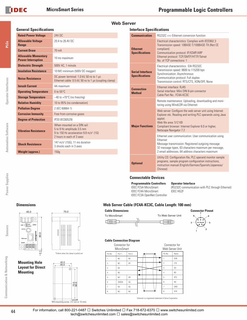
MicroSmart Series
44 www.idec.com
PLC
sO
pera
tor
Inte
rfac
esA
utom
atio
n S
oftw
are
Pow
er S
uppl
ies
Sen
sors
Com
mun
icat
ion
& N
etw
orki
ng
Programmable Logic Controllers
Web Server General Specifi cations
Rated Power Voltage 24V DC
Allowable Voltage Range
20.4 to 26.4V DC
Current Draw 70 mA
Allowable MomentaryPower Interruption
10 ms maximum
Dielectric Strength 500V AC, 1 minute
Insulation Resistance 10 MΩ minimum (500V DC megger)
Noise ResistanceDC power terminal: 1.0 kV, 50 ns to 1 μs Ethernet cable: 0.5 kV, 50 ns to 1 μs (coupling clamp)
Inrush Current 4A maximum
Operating Temperature 0 to 55°C
Storage Temperature –40 to +70°C (no freezing)
Relative Humidity 10 to 95% (no condensation)
Pollution Degree 2 (IEC 60664-1)
Corrosion Immunity Free from corrosive gases
Degree of Protection IP20 (IEC60529)
Vibration Resistance
When mounted on a DIN rail:5 to 9 Hz amplitude 3.5 mm9 to 150 Hz accelaration 9.8 m/s2 (1G)2 hours in each of 3 axes
Shock Resistance147 m/s2 (15G), 11 ms duration3 shocks each in 3 axes
Weight (approx.) 150g
Interface Specifi cations
Communication RS232C <=> Ethernet conversion function
EthernetSpecifi cations
Electrical characteristics: Complies with IEEE802.3Transmission speed: 10BASE-T/100BASE-TX (Not CE compliant)Communication protocol: IP/ICMP/ARPEthernet protocol: TCP/SMTP/HTTP/TelnetNo. of TCP connections: 1
Serial InterfaceSpecifi cations
Electrical characteristics: EIA RS232CTransmission speed: 9600 to 115200 bpsSynchronization: AsynchronousCommunication protocol: Full duplex Transmission control: RTS/CTS, XON/OFF, None
ConnectionMethod
Ethernet interface: RJ45Serial interface: Mini DIN 8-pin connectorCable Part No.: FC4A-KC3C
Major Functions
Remote maintenance: Uploading, downloading and moni-toring using WindLDR via Ethernet
Web server: Confi gure the web server unit using Internet Explorer etc. Reading and writing PLC operands using Java applet.Web fi le area: 512 KBCompliant browser: Internet Explorer 6.0 or higher, Netscape Navigator 7.2
Ethernet user communication: User communication using EthernetMessage transmission: Registered outgoing message32 message types, 63 characters maximum per message, 2 email addresses, 64 address characters maximum
Optional
Utility CD: Confi guration fi le, PLC operand monitor sample programs, sample program confi guration instructions, instruction manual (English/German/Spanish/Japanese/Chinese)
Connectable Devices
Programmable ControllersIDEC FC5A MicroSmartIDEC FC4A MicroSmartIDEC FC3A OpenNet Controller
Operator Interface(RS232C communication with PLC through Ethernet)IDEC HG2F
Dimensions
45.0
80.0
2.1
70.0
∗
*5.6mm when the clamp is pulled out
Mounting Hole Layout for Direct Mounting
45.035.0
80.0
70.0
M4 mounting screw (12 mm or 15 mm)
Web Server Cable (FC4A-KC3C, Cable Length: 100 mm)
Cable Dimensions
To MicroSmart To Web Server Unit
Connector Pinout
Cable Connection Diagram
Ethernet is a registered trademark of Xerox Corporation.
Pin No. Port 1 Port 2
1 NC RS
2 NC ER
3 SD
4 RD
5 NC DR
6 CMSW SG
7 SG SG
8 NC NC
Pin No. Name
1 DSR
2 CTS
3 SD
4 RD
5 RTS
6 NC
7 GND
8 DTR
Connector forMicroSmart
Connector for Web Server Unit
For information, call 800-221-0487 � Switches Unlimited � Fax 718-672-6370 � www.switchesunlimited.com [email protected] � [email protected]