programmable logic controller (plc) - introduction lecture 10
TRANSCRIPT

Programmable Logic Controller (PLC)
- Introduction
Lecture 10
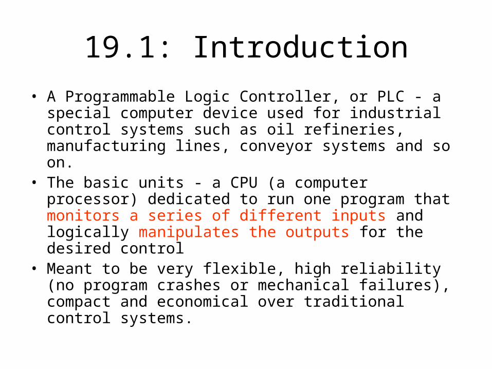
19.1: Introduction
• A Programmable Logic Controller, or PLC - a special computer device used for industrial control systems such as oil refineries, manufacturing lines, conveyor systems and so on.
• The basic units - a CPU (a computer processor) dedicated to run one program that monitors a series of different inputs and logically manipulates the outputs for the desired control
• Meant to be very flexible, high reliability (no program crashes or mechanical failures), compact and economical over traditional control systems.

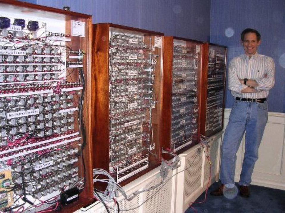
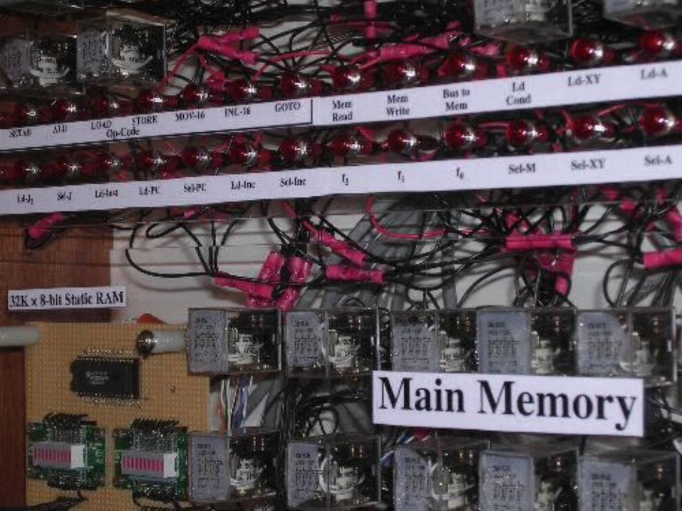
The Birth of the PLC
• The early history of the PLC is fascinating
• Started with a fifty foot long cabinet filled with relays whose function in life is to control a machine
• Wires run in and out of the system as the relays click and clack to the logic
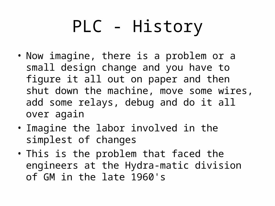
PLC - History
• Now imagine, there is a problem or a small design change and you have to figure it all out on paper and then shut down the machine, move some wires, add some relays, debug and do it all over again
• Imagine the labor involved in the simplest of changes
• This is the problem that faced the engineers at the Hydra-matic division of GM in the late 1960's
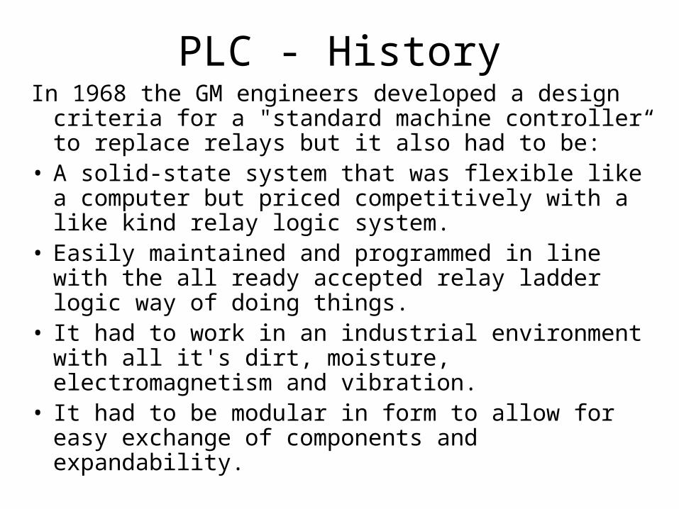
PLC - HistoryIn 1968 the GM engineers developed a design
criteria for a "standard machine controller“ to replace relays but it also had to be:
• A solid-state system that was flexible like a computer but priced competitively with a like kind relay logic system.
• Easily maintained and programmed in line with the all ready accepted relay ladder logic way of doing things.
• It had to work in an industrial environment with all it's dirt, moisture, electromagnetism and vibration.
• It had to be modular in form to allow for easy exchange of components and expandability.
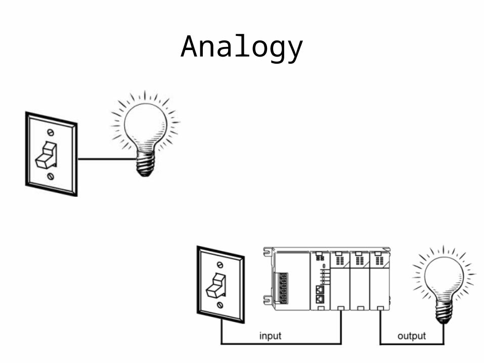
Analogy
21.1 Basic PLC structure
• Internal structure of PLC – a central processing unit (CPU), memory, input and output interfaces
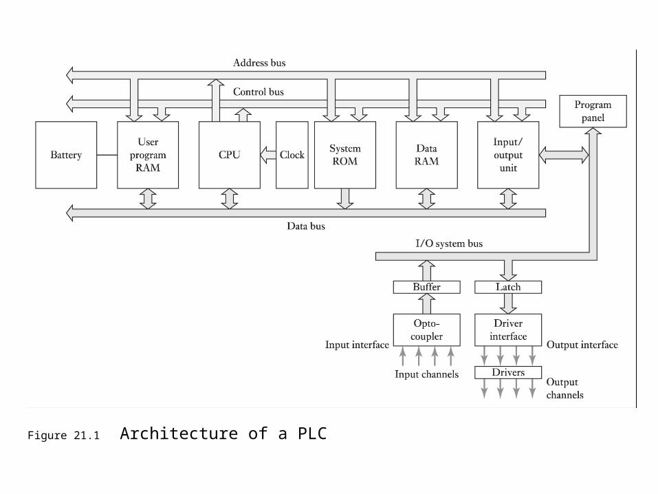
Figure 21.1 Architecture of a PLC
21.2: Basic PLC Hardware Structure
• The components that make a PLC work can be divided into three core areas.
1. The power supply and rack 2. The central processing unit (CPU) 3. The input/output (I/O) section • PLCs come in many shapes and sizes• Can be so small as to fit in shirt pocket or
modular rack based systems• “modular” because the rack can accept many
different types of I/O modules that simply slide into the rack and plug in

PLC Components

The Power Supply and Rack • The rack is the component
that holds everything together
• The rack has a backplane at the rear which allows the cards to communicate with the CPU
• The power supply plugs into the rack as well and supplies a regulated DC power to other modules that plug into the rack
• The most popular power supplies work with 120 VAC or 24 VDC sources.

The CPU (Central Processing Unit)• The brain of the whole PLC, manufacturers
offer different types of CPUs based on the complexity needed for the system.
• Consists - a microprocessor, memory chip and other integrated circuits to control logic, monitoring and communications
• Has different operating modes - in programming mode it accepts the downloaded logic from a PC, in run mode it executes the program and operates the process.
• PLC is a dedicated controller - process one program over and over again
CPU
• It is supplied with a clock of frequency 1 to 8 MHz
• The frequency determines operating speed of PLC and the timing and synchronisation of all PLC elements
• Same with PC – has address, control and data buses
• Memory elements: ROM – permanent storage for OS and fixed data, RAM –user’s program, and temporary buffer

CPU Operating cycleOne cycle through the program
is called a scan time:• Reading the inputs from the
other modules• Executing the logic based on
these inputs• Updating the outputs
accordinglyThe scan time happens very
quickly (in the range of 1/1000th of a second).

21.2.1: I/O System
• physical connection between the equipment and the PLC

• There are many different kinds of I/O cards
• Basically determine what inputs and outputs are needed, filling the rack with the appropriate cards and then addressing them correctly in the CPUs program.
I/O System

Inputs
• Input devices - digital or analog devices• Digital input - devices which give a signal that is
either on or off such as a pushbutton, limit switch, sensors or selector switches
• Analog input - converts a voltage or current (e.g. a signal that can be anywhere from 0 to 20mA) into a digitally equivalent number that can be understood by the CPU
• Examples - pressure transducers, flow meters and thermocouples for temperature readings

Pushbutton switch symbols, (a) normally open, (b) normally closed,
(c) both.
Outputs
• Output devices can also consist of digital or analog types. A digital output card either turns a device on or off such as lights, LEDs, small motors, and relays. An analog output card will convert a digital number sent by the CPU to it’s real world voltage or current. Typical outputs signals can range from 0-10 VDC or 4-20mA and are used to drive mass flow controllers, pressure regulators and position controls.

Relay cross section, (a) de-energized and (b) energized.

21.3: I/O Processing• Basic form of program - ladder programming,
each task – a rung of ladder• Sequence followed by PLC when carrying out
program:1. Scan input associated with one rung of a ladder
program2. Solve logic operation involving those inputs3. Set/reset output for that rung4. Move on to the next rung and repeat steps
1,2,3 5. End

21.4: Programming a PLC – Ladder programming
• The most widely used form of programming is called ladder logic
• Ladder logic uses symbols, instead of words, to emulate the real world relay logic control.
• These symbols are interconnected by lines to indicate the flow of current through relay like contacts and coils
• Over the years the number of symbols has increased to provide a high level of functionality.

• The completed program looks like a ladder but in reality it represents an electrical circuit
• The left and right rails indicate the positive and ground of a power supply
• The rungs represent the wiring between the different components which in the case of a PLC are all in the virtual world of the CPU
• In this simplest of examples a digital input (like a button connected to the first position on the card) when it is pressed turns on an output which energizes an indicator light.
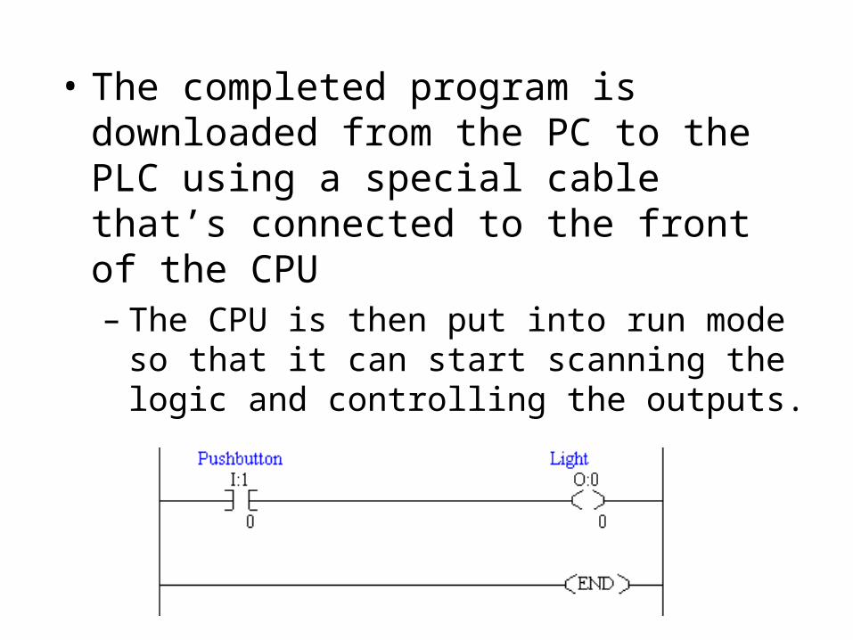
• The completed program is downloaded from the PC to the PLC using a special cable that’s connected to the front of the CPU– The CPU is then put into run mode so that it
can start scanning the logic and controlling the outputs.

PLC vs. PC (Personal Computers) PLC PC
Environment designed for harsh conditions with electrical noise, magnetic fields, vibration, extreme temperatures or humidity.
not designed for harsh environments. Industrial PCs are available but cost more
Ease of Use By design PLCs are friendlier to technicians since they are in ladder logic and have easy connections.
Operating systems like Windows are common. Connecting I/O to the PC is not always as easy.
Flexiblity PLCs in rack form are easy to exchange and add parts. They are designed for modularity and expansion.
Typical PCs are limited by the number of cards they can accommodate and are not easily expandable.
Speed PLCs execute a single program in sequential order. The have better ability to handle events in real time.
PCs, by design, are meant to handle simultaneous tasks. They have difficulty handling real time events

PLC vs. PC (Personal Computers)
PLC PC
Reliability A PLC never crashes over long periods of time. ("Never" may not be the right word but its close enough to be true.)
A PC locking up and crashing is frequent.
Programming languages Languages are typically fixed to ladder logic, function block or structured text.
A PC is very flexible and powerful in what to use for programming.
Data management Memory is limited in its ability to store a lot of data.
This is where the PC excels because of it's hard drive. Any long term data storage, history and trending is best done on a PC.
Cost incomparable incomparable

End of Lecture 10