programmable controller twido - barr-thorp · programmable controller twido 05 catalog january this...
TRANSCRIPT
Programmable controllerTwido
05CatalogJanuary
This document provided by Barr-Thorp Electric Co., Inc. 800-473-9123 www.barr-thorp.com

This document provided by Barr-Thorp Electric Co., Inc. 800-473-9123 www.barr-thorp.com
Contents Twido programmable controller
n New
New, extended functions are offered with Twido programmable controllers versions u 3.0 and with version 3.0 of TwidoSoft software:
n Incorporation of the new CANopen bus master module TWD NCO1M in the Twido programmable controller range allows the Twido master to manage up to 16 slaves (motor starters, variable speed drives, etc.) connected to the CANopen bus.n Connection to the Ethernet network:- an integrated RJ45 port (Modbus TCP protocol) is available on the new 40 I/O Twido compact base controller TWD LCAE 40DRF,- a new TwidoPort 499 TWD 01100 interface module also allows all Twido programmable controllers, versions u 3.0, to be connected to Ethernet via one of the serial ports on the controller.n A new gateway VW3 A8114, using Bluetooth technology, allows wireless communication between a programming PC or a Pocket PC and a Twido compact or modular programmable controller.n Four new analog I/O expansion modules TWD AMI 4LT/8HT, TWD ARI 8HT and TWD AVO 2HT have been added to the Twido programmable controller range.n A new system of macros for managing the slaves connected on a Modbus network or a CANopen bus allows easier programming of applications with TwidoSoft software version 3.0, by simplifying writing of the program and improving comprehension of the code.n The new TwidoAdjust software package TWD SMD 100p V30M is a software tool dedicated to the management and animation of Twido applications, using a Pocket PC.
Compact and modular base controllersSelection guide . . . . . . . . . . . . . . . . . . . . . . . . . . . . . . . . . . . . . . . . pages 4 and 5
b Compact base . . . . . . . . . . . . . . . . . . . . . . . . . . . . . . . . . . . . . . . . . pages 6 to 11
b Modular base . . . . . . . . . . . . . . . . . . . . . . . . . . . . . . . . . . . . . . . . . pages 12 to 17
I/O modulesSelection guide discrete I/O modules . . . . . . . . . . . . . . . . . . . . . . pages 18 to 21
b Discrete I/O modules . . . . . . . . . . . . . . . . . . . . . . . . . . . . . . . . . . . pages 22 to 29
Selection guide analog I/O modules . . . . . . . . . . . . . . . . . . . . . pages 30 and 31
b Analog I/O modules . . . . . . . . . . . . . . . . . . . . . . . . . . . . . . . . . . . . pages 32 to 37
b Master module for installation system AS-Interface . . . . . . . . . . pages 38 and 39
Communicationb CANopen bus master module, TwidoPort interface module and
communication protocols . . . . . . . . . . . . . . . . . . . . . . . . . . . . . . . . pages 40 to 47
Advantys, Telefast® pre-wired system for TwidoSelection guide . . . . . . . . . . . . . . . . . . . . . . . . . . . . . . . . . . . . . . pages 48 and 49
b I/O connection sub-bases . . . . . . . . . . . . . . . . . . . . . . . . . . . . . . . pages 50 to 63
Softwareb TwidoSoft programming software . . . . . . . . . . . . . . . . . . . . . . . . . pages 64 to 71
b TwidoAdjust software . . . . . . . . . . . . . . . . . . . . . . . . . . . . . . . . . pages 72 and 73
Servicesb Product reference index . . . . . . . . . . . . . . . . . . . . . . . . . . . . . . . . . . . . . . page 74
b Community regulations, protective treatment of equipment . . . . . . . . . . . page 75
3This document provided by Barr-Thorp Electric Co., Inc. 800-473-9123 www.barr-thorp.com
Selection guide 0 Twido programmable controller 0
Compact and modular base controllers
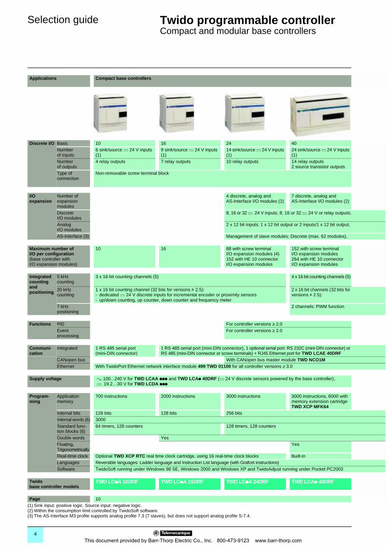
Applications Compact base controllers
Discrete I/O Basic 10 16 24 40Number of inputs
6 sink/source c 24 V inputs (1)
9 sink/source c 24 V inputs (1)
14 sink/source c 24 V inputs (1)
24 sink/source c 24 V inputs (1)
Number of outputs
4 relay outputs 7 relay outputs 10 relay outputs 14 relay outputs2 source transistor outputs
Type of connection
Non-removable screw terminal block
I/O expansion
Number of expansion modules
4 discrete, analog and AS-Interface I/O modules (2)
7 discrete, analog and AS-Interface I/O modules (2)
Discrete I/O modules
8, 16 or 32 c 24 V inputs; 8, 16 or 32 c 24 V or relay outputs;
Analog I/O modules
2 x 12 bit inputs; 1 x 12 bit output or 2 inputs/1 x 12 bit output,
AS-Interface (3) Management of slave modules: Discrete (max. 62 modules),
Maximum number ofI/O per configuration (base controller with I/O expansion modules)
10 16 88 with screw terminal I/O expansion modules (4)152 with HE 10 connector I/O expansion modules
152 with screw terminal I/O expansion modules264 with HE 10 connector I/O expansion modules
Integrated counting and positioning
5 kHz counting
3 x 16 bit counting channels (5) 4 x 16 bit counting channels (5)
20 kHz counting
1 x 16 bit counting channel (32 bits for versions u 2.5):- dedicated c 24 V discrete inputs for incremental encoder or proximity sensors- up/down counting, up counter, down counter and frequency meter
2 x 16 bit channels (32 bits for versions u 2.5):
7 kHz positioning
2 channels: PWM function
Functions PID For controller versions ≥ 2.0Event processing
For controller versions ≥ 2.0
Communi-cation
Integrated 1 RS 485 serial port (mini-DIN connector)
1 RS 485 serial port (mini-DIN connector), 1 optional serial port: RS 232C (mini-DIN connector) or RS 485 (mini-DIN connector or screw terminals) + RJ45 Ethernet port for TWD LCAE 40DRF
CANopen bus With CANopen bus master module TWD NCO1MEthernet With TwidoPort Ethernet network interface module 499 TWD 01100 for all controller versions ≥ 3.0
Supply voltage a 100...240 V for TWD LCAA ppp and TWD LCAp 40DRF (c 24 V discrete sensors powered by the base controller), c 19.2…30 V for TWD LCDA ppp
Program-ming
Application memory
700 instructions 2000 instructions 3000 instructions 3000 instructions, 6000 with memory extension cartridge TWD XCP MFK64
Internal bits 128 bits 128 bits 256 bitsInternal words (6) 3000Standard func-tion blocks (6)
64 timers, 128 counters 128 timers, 128 counters
Double words YesFloating, Trigonometrically
Yes
Real-time clock Optional TWD XCP RTC real time clock cartridge, using 16 real-time clock blocks Built-inLanguages Reversible languages: Ladder language and Instruction List language (with Grafcet instructions)Software TwidoSoft running under Windows 98 SE, Windows 2000 and Windows XP and TwidoAdjust running under Pocket PC2003
Twido base controller models
TWD LCpA 10DRF TWD LCpA 16DRF TWD LCpA 24DRF TWD LCAp 40DRF
Page 10(1) Sink input: positive logic. Source input: negative logic.(2) Within the consumption limit controlled by TwidoSoft software.(3) The AS-Interface M3 profile supports analog profile 7.3 (7 slaves), but does not support analog profile S-7.4.
4This document provided by Barr-Thorp Electric Co., Inc. 800-473-9123 www.barr-thorp.com

00
Modular base controllers
20 4012 sink/source c 24 V inputs (1) 24 sink/source c 24 V inputs (1)
8 sink or source transistor outputs (depending on model)
6 relay outputs and 2 transistor source outputs 16 sink or source transistor outputs (depending on model)
By HE10 type connectorFor TWD LMDA 20DTK, allows use of the Telefast pre-wired system
By removable screw terminal block By HE10 type connectorFor TWD LMDA 40DTK, allows use of the Telefast pre-wired system
4 discrete, analog and AS-Interface I/O modules (2) 7 discrete, analog and AS-Interface I/O modules (2)
4 c 24 V inputs/4 relay outputs or 16 c 24 V inputs/8 relay outputs, connection by screw or spring terminals and by HE 10 type connector
connection by screw terminals, 8 x 10 bit inputs, 4 x 12 bit inputs, 2 x 10 bit outputs
analog (max. 7 modules). For all controller versions ≥ 2.0
84 with screw terminal I/O expansion modules148 with HE 10 connector I/O expansion modules
132 with screw terminal I/O expansion modules244 with HE 10 connector I/O expansion modules
152 with screw terminal I/O expansion modules264 with HE 10 connector I/O expansion modules
2 x 16 bit counting channels (5)
- dedicated c 24 V discrete inputs for incremental encoders or proximity sensors- up/down counting, up counter, down counter, frequency meter
(pulse width modulation output) and PLS function (pulse generator output)
For all controller versions ≥ 2.0For all controller versions ≥ 2.0
for controller versions ≥ 3.0
c 24 V supply
3000 instructions 3000 instructions, 6000 with memory extension cartridge TWD XCP MFK64
Yes
Optional TWD XCP RTC real time clock cartridge, using 16 real-time clock blocks
TWD LMDA 20DpK (7) TWD LMDA 20DRT TWD LMDA 40DpK (7)
16(4) With maximum of 42 relay outputs (on base controller and I/O expansions).(5) Dedicated c 24 V discrete inputs of the base controller and up/down counting with preset.(6) The maximum values of the internal words and function blocks cannot be cumulated.(7) Replace the p in the reference with T: source transistor outputs, U: sink transistor outputs.
5This document provided by Barr-Thorp Electric Co., Inc. 800-473-9123 www.barr-thorp.com
Presentation 0 Twido programmable controller 0
Compact base controllers
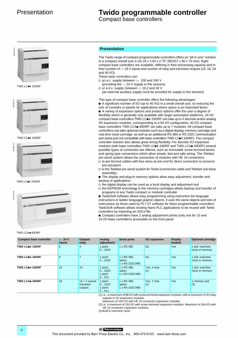
The Twido range of compact programmable controllers offers an “all-in-one” solution in a compact overall size 3.1/6.18 x 3.54 x 2.75" (80/157 x 90 x 70 mm). Eight compact base controllers are available, differing in their processing capacity and in their number of c 24 V inputs and number of relay and transistor outputs (10, 16, 24 and 40 I/O). These base controllers use:v an a.c. supply between a 100 and 240 V
(providing the c 24 V supply to the sensors)v or a d.c. supply, between c 19.2 and 30 V
(an external auxiliary supply must be provided for supply to the sensors)
This type of compact base controller offers the following advantages: b A significant number of I/O (up to 40 I/O) in a small overall size, so reducing the size of consoles or panels for applications where space is an important factor.b A variety of expansion options and product options offer the user a degree of flexibility which is generally only available with larger automation platforms. 24 I/O compact base controllers TWD LCpA 24DRF can take up to 4 discrete and/or analog I/O expansion modules, corresponding to a 64 I/O configuration; 40 I/O compact base controllers TWD LCAp 40DRF can take up to 7 modules. All compact base controllers can take optional modules such as a digital display, memory cartridge and real-time clock cartridge, as well as an additional RS 485 or RS 232C communication port (extra port not compatible with base controllers TWD LCpA 10DRF). The compact controller solution also allows great wiring flexibility. For discrete I/O expansion modules (with base controllers TWD LCpA 24DRF and TWD LCAp 40DRF) several possible types of connection are offered, such as removable screw terminal blocks and spring type connections which allow simple, fast and safe wiring. The Telefast pre-wired system allows the connection of modules with HE 10 connectors:v to pre-formed cables with free wires at one end for direct connection to sensors/
pre-actuatorsv to the Telefast pre-wired system for Twido (connection cable and Telefast sub-base
assembly). b The display and plug-in memory options allow easy adjustment, transfer and backup of applications: v the digital display can be used as a local display and adjustment toolv the EEPROM technology in the memory cartridges allows backup and transfer of
programs to any Twido compact or modular controllerb TwidoSoft software allows easy programming using instruction list language instructions or ladder language graphic objects. It uses the same objects and sets of instructions as those used by PL7-07 software for Nano programmable controllers. TwidoSoft software allows existing Nano PLC applications to be reused with Twido controllers by importing an ASCII file. b Compact controllers have 2 analog adjustment points (only one for 10 and 16 I/O base controllers) accessible on the front panel.
Presentation
TWD LCpA 10DRF
5644
93-3
-3
TWD LCpA 16DRF
5644
93-3
-3
TWD LCpA 24DRF
5644
94-3
-3
TWD LCAp 40DRF
1211
14-4
9-M
Compact base controller c 24 V inputs
Outputsrelay
Analog adjustment
Serial ports I/O expansion Display module
Optional cartridge
TWD LCpA 10DRF 6 4 1 point 0…1023
1 x RS 485 No Yes 1 slot: real-time clock or memory
TWD LCpA 16DRF 9 7 1 point 0…1023
1 x RS 485,option1 x RS 232C/485
No Yes 1 slot: real-time clock or memory
TWD LCpA 24DRF 14 10 1 point 0…10231 point 0…511
1 x RS 485,option1 x RS 232C/485
Yes, 4 max(1)
Yes 1 slot: real-time clock or memory
TWD LCAp 40DRF 24 14 + 2 source transistor outputs
1 point 0…10231 point 0…511
1 x RS 485,option1 x RS 232C/485
Yes, 7 max(2)
Yes 1 memory slot(3)
(1) i.e.: a maximum of 88 I/O with screw terminal expansion modules, with a maximum of 32 relay outputs in I/O expansion modules. Maximum of 152 I/O with HE 10 connector expansion modules.
(2) i.e. a maximum of 152 I/O with screw terminal expansion modules. Maximum of 264 I/O with HE 10 connector expansion modules.
(3) Built-in real-time clock.
6This document provided by Barr-Thorp Electric Co., Inc. 800-473-9123 www.barr-thorp.com
Description 0 Twido programmable controller 0
Compact base controllers
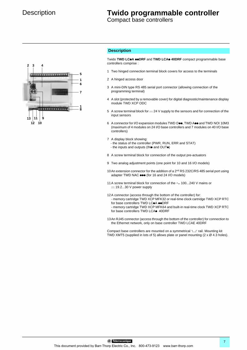
Twido TWD LCpA ppDRF and TWD LCAp 40DRF compact programmable base controllers comprise :
1 Two hinged connection terminal block covers for access to the terminals
2 A hinged access door
3 A mini-DIN type RS 485 serial port connector (allowing connection of the programming terminal)
4 A slot (protected by a removable cover) for digital diagnostic/maintenance display module TWD XCP ODC
5 A screw terminal block for c 24 V supply to the sensors and for connection of the input sensors
6 A connector for I/O expansion modules TWD Dpp, TWD App and TWD NOI 10M3 (maximum of 4 modules on 24 I/O base controllers and 7 modules on 40 I/O base controllers)
7 A display block showing:- the status of the controller (PWR, RUN, ERR and STAT)- the inputs and outputs (INp and OUTp)
8 A screw terminal block for connection of the output pre-actuators
9 Two analog adjustment points (one point for 10 and 16 I/O models)
10An extension connector for the addition of a 2nd RS 232C/RS 485 serial port using adapter TWD NAC ppp (for 16 and 24 I/O models)
11A screw terminal block for connection of the a 100...240 V mains or c 19.2...30 V power supply
12A connector (access through the bottom of the controller) for:- memory cartridge TWD XCP MFK32 or real-time clock cartridge TWD XCP RTC for base controllers TWD LCpA ppDRF- memory cartridge TWD XCP MFK64 and built-in real-time clock TWD XCP RTC for base controllers TWD LCAp 40DRF
13An RJ45 connector (access through the bottom of the controller) for connection to the Ethernet network, only on base controller TWD LCAE 40DRF
Compact base controllers are mounted on a symmetrical 5 rail. Mounting kit TWD XMT5 (supplied in lots of 5) allows plate or panel mounting (2 x Ø 4.3 holes).
Description
1
2 3 4
5
6
7
8
910
1112
1
13
7This document provided by Barr-Thorp Electric Co., Inc. 800-473-9123 www.barr-thorp.com
Characteristics 0 Twido programmable controller 0
Compact base controllers
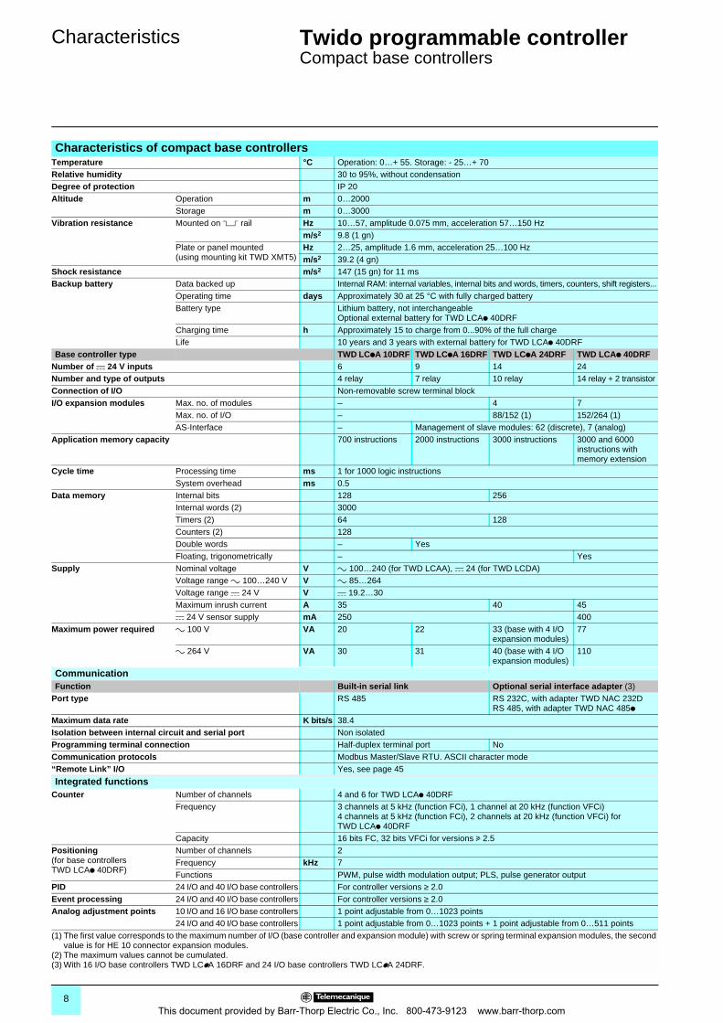
Characteristics of compact base controllersTemperature °C Operation: 0…+ 55. Storage: - 25…+ 70Relative humidity 30 to 95%, without condensationDegree of protection IP 20Altitude Operation m 0…2000
Storage m 0…3000Vibration resistance Mounted on 5 rail Hz 10…57, amplitude 0.075 mm, acceleration 57…150 Hz
m/s2 9.8 (1 gn)Plate or panel mounted (using mounting kit TWD XMT5)
Hz 2…25, amplitude 1.6 mm, acceleration 25…100 Hzm/s2 39.2 (4 gn)
Shock resistance m/s2 147 (15 gn) for 11 msBackup battery Data backed up Internal RAM: internal variables, internal bits and words, timers, counters, shift registers...
Operating time days Approximately 30 at 25 °C with fully charged batteryBattery type Lithium battery, not interchangeable
Optional external battery for TWD LCAp 40DRFCharging time h Approximately 15 to charge from 0...90% of the full chargeLife 10 years and 3 years with external battery for TWD LCAp 40DRF
Base controller type TWD LCpA 10DRF TWD LCpA 16DRF TWD LCpA 24DRF TWD LCAp 40DRFNumber of c 24 V inputs 6 9 14 24Number and type of outputs 4 relay 7 relay 10 relay 14 relay + 2 transistorConnection of I/O Non-removable screw terminal blockI/O expansion modules Max. no. of modules – 4 7
Max. no. of I/O – 88/152 (1) 152/264 (1)AS-Interface – Management of slave modules: 62 (discrete), 7 (analog)
Application memory capacity 700 instructions 2000 instructions 3000 instructions 3000 and 6000 instructions with memory extension
Cycle time Processing time ms 1 for 1000 logic instructionsSystem overhead ms 0.5
Data memory Internal bits 128 256Internal words (2) 3000Timers (2) 64 128Counters (2) 128Double words – YesFloating, trigonometrically – Yes
Supply Nominal voltage V a 100…240 (for TWD LCAA), c 24 (for TWD LCDA)Voltage range a 100…240 V V a 85…264Voltage range c 24 V V c 19.2…30Maximum inrush current A 35 40 45c 24 V sensor supply mA 250 400
Maximum power required a 100 V VA 20 22 33 (base with 4 I/O expansion modules)
77
a 264 V VA 30 31 40 (base with 4 I/O expansion modules)
110
CommunicationFunction Built-in serial link Optional serial interface adapter (3)
Port type RS 485 RS 232C, with adapter TWD NAC 232DRS 485, with adapter TWD NAC 485p
Maximum data rate K bits/s 38.4Isolation between internal circuit and serial port Non isolatedProgramming terminal connection Half-duplex terminal port NoCommunication protocols Modbus Master/Slave RTU. ASCII character mode“Remote Link” I/O Yes, see page 45
Integrated functionsCounter Number of channels 4 and 6 for TWD LCAp 40DRF
Frequency 3 channels at 5 kHz (function FCi), 1 channel at 20 kHz (function VFCi)4 channels at 5 kHz (function FCi), 2 channels at 20 kHz (function VFCi) for TWD LCAp 40DRF
Capacity 16 bits FC, 32 bits VFCi for versions u 2.5Positioning(for base controllers TWD LCAp 40DRF)
Number of channels 2Frequency kHz 7Functions PWM, pulse width modulation output; PLS, pulse generator output
PID 24 I/O and 40 I/O base controllers For controller versions ≥ 2.0Event processing 24 I/O and 40 I/O base controllers For controller versions ≥ 2.0Analog adjustment points 10 I/O and 16 I/O base controllers 1 point adjustable from 0…1023 points
24 I/O and 40 I/O base controllers 1 point adjustable from 0…1023 points + 1 point adjustable from 0…511 points(1) The first value corresponds to the maximum number of I/O (base controller and expansion module) with screw or spring terminal expansion modules, the second
value is for HE 10 connector expansion modules.(2) The maximum values cannot be cumulated.(3) With 16 I/O base controllers TWD LCpA 16DRF and 24 I/O base controllers TWD LCpA 24DRF.
8This document provided by Barr-Thorp Electric Co., Inc. 800-473-9123 www.barr-thorp.com
Characteristics (continued) 0 Twido programmable controller 0
Compact base controllers
c input characteristics Base controller type TWD LCpA
10DRFTWD LCpA 16DRF
TWD LCpA 24DRF
TWD LCAA 40DRF
TWD LCAE 40DRF
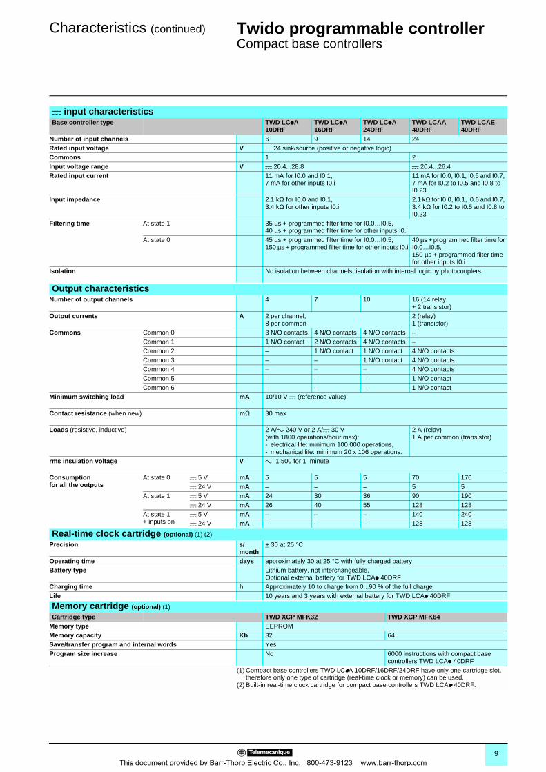
Number of input channels 6 9 14 24Rated input voltage V c 24 sink/source (positive or negative logic)Commons 1 2Input voltage range V c 20.4...28.8 c 20.4...26.4Rated input current 11 mA for I0.0 and I0.1,
7 mA for other inputs I0.i11 mA for I0.0, I0.1, I0.6 and I0.7, 7 mA for I0.2 to I0.5 and I0.8 to I0.23
Input impedance 2.1 kΩ for I0.0 and I0.1, 3.4 kΩ for other inputs I0.i
2.1 kΩ for I0.0, I0.1, I0.6 and I0.7, 3.4 kΩ for I0.2 to I0.5 and I0.8 to I0.23
Filtering time At state 1 35 µs + programmed filter time for I0.0…I0.5,40 µs + programmed filter time for other inputs I0.i
At state 0 45 µs + programmed filter time for I0.0…I0.5,150 µs + programmed filter time for other inputs I0.i
40 µs + programmed filter time for I0.0…I0.5,150 µs + programmed filter time for other inputs I0.i
Isolation No isolation between channels, isolation with internal logic by photocouplers
Output characteristicsNumber of output channels 4 7 10 16 (14 relay
+ 2 transistor)Output currents A 2 per channel,
8 per common2 (relay)1 (transistor)
Commons Common 0 3 N/O contacts 4 N/O contacts 4 N/O contacts –Common 1 1 N/O contact 2 N/O contacts 4 N/O contacts –Common 2 – 1 N/O contact 1 N/O contact 4 N/O contactsCommon 3 – – 1 N/O contact 4 N/O contactsCommon 4 – – – 4 N/O contactsCommon 5 – – – 1 N/O contactCommon 6 – – – 1 N/O contact
Minimum switching load mA 10/10 V c (reference value)
Contact resistance (when new) mΩ 30 max
Loads (resistive, inductive) 2 A/a 240 V or 2 A/c 30 V (with 1800 operations/hour max):- electrical life: minimum 100 000 operations,- mechanical life: minimum 20 x 106 operations.
2 A (relay)1 A per common (transistor)
rms insulation voltage V a 1 500 for 1 minute
Consumption for all the outputs
At state 0 c 5 V mA 5 5 5 70 170c 24 V mA – – – 5 5
At state 1 c 5 V mA 24 30 36 90 190c 24 V mA 26 40 55 128 128
At state 1+ inputs on
c 5 V mA – – – 140 240c 24 V mA – – – 128 128
Real-time clock cartridge (optional) (1) (2)
Precision s/month
+ 30 at 25 °C
Operating time days approximately 30 at 25 °C with fully charged batteryBattery type Lithium battery, not interchangeable.
Optional external battery for TWD LCAp 40DRFCharging time h Approximately 10 to charge from 0...90 % of the full chargeLife 10 years and 3 years with external battery for TWD LCAp 40DRF
Memory cartridge (optional) (1)
Cartridge type TWD XCP MFK32 TWD XCP MFK64Memory type EEPROMMemory capacity Kb 32 64Save/transfer program and internal words YesProgram size increase No 6000 instructions with compact base
controllers TWD LCAp 40DRF(1) Compact base controllers TWD LCpA 10DRF/16DRF/24DRF have only one cartridge slot,
therefore only one type of cartridge (real-time clock or memory) can be used.(2) Built-in real-time clock cartridge for compact base controllers TWD LCAp 40DRF.
9This document provided by Barr-Thorp Electric Co., Inc. 800-473-9123 www.barr-thorp.com
References 0 Twido programmable controller 0
Compact base controllers
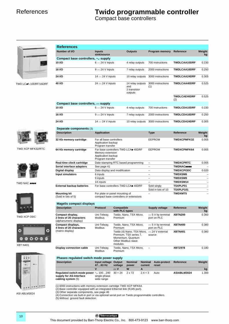
ReferencesNumber of I/O Inputs
sink/sourceOutputs Program memory Reference Weight
kg
Compact base controllers, a supply10 I/O 6 c 24 V inputs 4 relay outputs 700 instructions TWDLCAA10DRF 0.230
16 I/O 9 c 24 V inputs 7 relay outputs 2000 instructions TWDLCAA16DRF 0.250
24 I/O 14 c 24 V inputs 10 relay outputs 3000 instructions TWDLCAA24DRF 0.305
40 I/O 24 c 24 V inputs 14 relay outputs and2 transistor outputs
3000 instructions(1)
TWDLCAA40DRF 0.525
TWDLCAE40DRF(2)
0.525
Compact base controllers, c supply10 I/O 6 c 24 V inputs 4 relay outputs 700 instructions TWDLCDA10DRF 0.230
16 I/O 9 c 24 V inputs 7 relay outputs 2000 instructions TWDLCDA16DRF 0.250
24 I/O 14 c 24 V inputs 10 relay outputs 3000 instructions TWDLCDA24DRF 0.305
Separate components (3)
Description Application Type Reference Weightkg
32 Kb memory cartridge For all base controllersApplication backupProgram transfer
EEPROM TWDXCPMFK32 0.005
64 Kb memory cartridge For base controllers TWD LCAp 40DRFMemory extensionApplication backupProgram transfer
EEPROM TWDXCPMFK64 0.005
Real-time clock cartridge Date-stamping RTC based programming – TWDXCPRTC 0.005Serial interface adapters See page 41 – TWDNACpppp –Digital display Data display and modification – TWDXCPODC 0.020Input simulators 6 inputs – TWDXSM6 –
9 inputs – TWDXSM9 –14 inputs – TWDXSM14 –
External backup batteries For base controllers TWD LCAp 40DRF Sold singly TSXPLP01 –Sold in lots of 10 TSXPLP101 –
Mounting kit(Sold in lots of 5)
For plate or panel mounting of compact base controllers or extensions
– TWDXMT5 –
Magelis compact displaysDescription Protocol Compatible
with PLC typesSupply voltage Reference Weight
kgCompact display, 2 lines of 20 characters(alphanumeric display)
Uni-Telway, Modbus
Twido, Nano, TSX Micro, Premium
c 5 V by terminal port on PLC
XBTN200 0.360
Compact displays, 4 lines of 20 characters(matrix display)
Uni-Telway, Modbus
Twido, Nano, TSX Micro, Premium
c 5 V by terminal port on PLC
XBTN400 0.360
Twido (4) Nano, TSX Micro, Premium, TSX series 7, Momentum, Quantum Other Modbus slave modules
c 24 V external source
XBTN401 0.360
Display connection cable Uni-Telway, Modbus
Twido, Nano, TSX Micro, Premium
– XBTZ978 0.180
Phaseo regulated switch mode power supplyDescription Input voltage
47…63 HzOutput voltage
Nominal power
Nominal current
Auto-protect reset
Reference Weight
V c V W A kgRegulated switch mode power supply for AS-Interface cabling system (5)
a 100…240 single-phase wide range
30 + 24 2 x 72 2.4 + 3 Auto ASIABLM3024 1.300
(1) 6000 instructions with memory extension cartridge TWD XCP MFK64.(2) Base controller equipped with an integrated Ethernet link (RJ45 port).(3) Other separate components, see page 46(4) Connection via built-in port or via optional serial port on Twido programmable controllers.(5) Without ground fault detection.
TWD LCpA 10DRF/16DRF
TWD XCP MFK32/RTC
TWD NAC pppp
TWD XCP ODC
XBT N401
ASI ABLM3024
10This document provided by Barr-Thorp Electric Co., Inc. 800-473-9123 www.barr-thorp.com
Dimensions,connections 0
Twido programmable controller 0
Compact base controllers
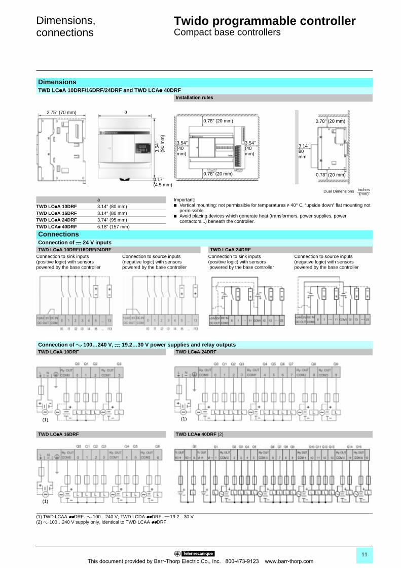
DimensionsTWD LCpA 10DRF/16DRF/24DRF and TWD LCAp 40DRF
Installation rules
a Important:b Vertical mounting: not permissible for temperatures u 40° C, “upside down” flat mounting not
permissible.b Avoid placing devices which generate heat (transformers, power supplies, power
contactors...) beneath the controller.
TWD LCpA 10DRF 3.14" (80 mm)TWD LCpA 16DRF 3.14" (80 mm)TWD LCpA 24DRF 3.74" (95 mm)TWD LCAp 40DRF 6.18" (157 mm)
ConnectionsConnection of c 24 V inputsTWD LCpA 10DRF/16DRF/24DRF TWD LCpA 24DRF
Connection to sink inputs (positive logic) with sensors powered by the base controller
Connection to source inputs (negative logic) with sensors powered by the base controller
Connection to sink inputs (positive logic) with sensors powered by the base controller
Connection to source inputs (negative logic) with sensors powered by the base controller
Connection of a 100…240 V, c 19.2…30 V power supplies and relay outputsTWD LCpA 10DRF TWD LCpA 24DRF
TWD LCpA 16DRF TWD LCAp 40DRF (2)
(1) TWD LCAA ppDRF: a 100…240 V, TWD LCDA ppDRF: c 19.2…30 V.(2) a 100…240 V supply only, identical to TWD LCAA ppDRF.
2.75" (70 mm) a
3.54
" (9
0 m
m)
0.17"(4.5 mm)
0.78" (20 mm)
3.54"(40mm)
3.54"(40 mm)
0.78" (20 mm)
3.14"80 mm
0.78" (20 mm)
0.78" (20 mm)
Dual Dimensions inches(mm)
(1) (1)
(1)
11This document provided by Barr-Thorp Electric Co., Inc. 800-473-9123 www.barr-thorp.com
Presentation 0 Twido programmable controller 0
Modular base controllers
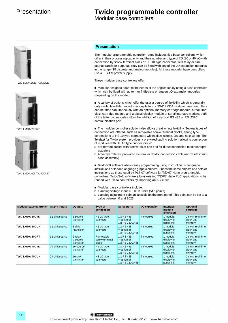
The modular programmable controller range includes five base controllers, which differ in their processing capacity and their number and type of I/O (20 or 40 I/O with connection by screw terminal block or HE 10 type connector, with relay or sink/source transistor outputs). They can be fitted with any of the I/O expansion modules in the range (18 discrete and analog modules). All these modular base controllers use a c 24 V power supply.
These modular base controllers offer:
b Modular design to adapt to the needs of the application by using a base controller which can be fitted with up to 4 or 7 discrete or analog I/O expansion modules (depending on the model).
b A variety of options which offer the user a degree of flexibility which is generally only available with larger automation platforms. TWD LMDA modular base controllers can be fitted simultaneously with an optional memory cartridge module, a real-time clock cartridge module and a digital display module or serial interface module; both of the latter two modules allow the addition of a second RS 485 or RS 232C communication port.
b The modular controller solution also allows great wiring flexibility. Several types of connection are offered, such as removable screw terminal blocks, spring type connections or HE 10 type connectors which allow simple, fast and safe wiring. The Telefast for Twido system provides a pre-wired cabling solution, allowing connection of modules with HE 10 type connectors to:v pre-formed cables with free wires at one end for direct connection to sensors/pre-
actuatorsv Advantys Telefast pre-wired system for Twido (connection cable and Telefast sub-
base assembly)
b TwidoSoft software allows easy programming using instruction list language instructions or ladder language graphic objects. It uses the same objects and sets of instructions as those used by PL7-07 software for TSX07 Nano programmable controllers. TwidoSoft software allows existing TSX07 Nano PLC applications to be reused with Twido controllers by importing an ASCII file.
b Modular base controllers include:v 1 analog voltage input, 0...10 V 9 bits (512 points)v 1 analog adjustment point accessible on the front panel. This point can be set to a
value between 0 and 1023
Presentation
TWD LMDA 20DTK/20DUK
TWD LMDA 20DRT
TWD LMDA 40DTK/40DUK
Modular base controller c 24V inputs Outputs Type of connection
Serial ports I/O expansion Interface module extension
Optional cartridge
TWD LMDA 20DTK 12 sink/source 8 source transistor
HE 10 type connector
1 x RS 485,+ option of 1 x RS 232C/485
4 modules 1 module: display or serial link
2 slots: real-time clock and memory
TWD LMDA 20DUK 12 sink/source 8 sink transistor
HE 10 type connector
1 x RS 485,+ option of 1 x RS 232C/485
4 modules 1 module: display or serial link
2 slots: real-time clock and memory
TWD LMDA 20DRT 12 sink/source 6 relay,2 source transistor
Removable screw terminal block
1 x RS 485,+ option of 1 x RS 232C/485
7 modules 1 module: display orserial link
2 slots: real-time clock and memory
TWD LMDA 40DTK 24 sink/source 16 source transistor
HE 10 type connector
1 x RS 485,+ option of 1 x RS 232C/485
7 modules 1 module: display or serial link
2 slots: real-time clock and memory
TWD LMDA 40DUK 24 sink/source 16 sink transistor
HE 10 type connector
1 x RS 485,+ option of 1 x RS 232C/485
7 modules 1 module: display or serial link
2 slots: real-time clock and memory
12This document provided by Barr-Thorp Electric Co., Inc. 800-473-9123 www.barr-thorp.com
Description 0 Twido programmable controller 0
Modular base controllers
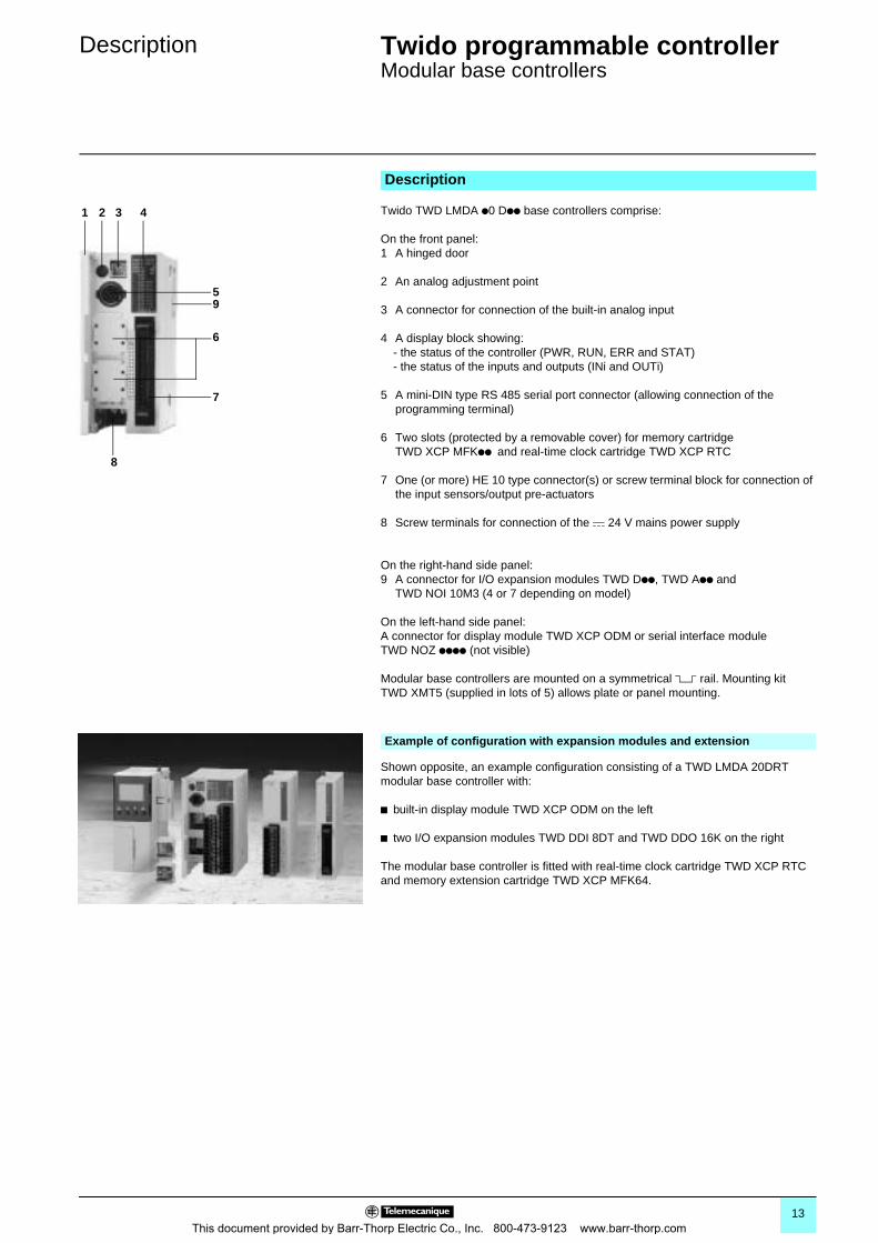
Twido TWD LMDA p0 Dpp base controllers comprise:
On the front panel: 1 A hinged door
2 An analog adjustment point
3 A connector for connection of the built-in analog input
4 A display block showing:- the status of the controller (PWR, RUN, ERR and STAT)- the status of the inputs and outputs (INi and OUTi)
5 A mini-DIN type RS 485 serial port connector (allowing connection of the programming terminal)
6 Two slots (protected by a removable cover) for memory cartridge TWD XCP MFKpp and real-time clock cartridge TWD XCP RTC
7 One (or more) HE 10 type connector(s) or screw terminal block for connection of the input sensors/output pre-actuators
8 Screw terminals for connection of the c 24 V mains power supply
On the right-hand side panel:9 A connector for I/O expansion modules TWD Dpp, TWD App and
TWD NOI 10M3 (4 or 7 depending on model)
On the left-hand side panel:A connector for display module TWD XCP ODM or serial interface module TWD NOZ pppp (not visible)
Modular base controllers are mounted on a symmetrical 5 rail. Mounting kit TWD XMT5 (supplied in lots of 5) allows plate or panel mounting.
Shown opposite, an example configuration consisting of a TWD LMDA 20DRT modular base controller with:
b built-in display module TWD XCP ODM on the left
b two I/O expansion modules TWD DDI 8DT and TWD DDO 16K on the right
The modular base controller is fitted with real-time clock cartridge TWD XCP RTC and memory extension cartridge TWD XCP MFK64.
Description
1 2 3 4
5
6
7
8
9
Example of configuration with expansion modules and extension
13This document provided by Barr-Thorp Electric Co., Inc. 800-473-9123 www.barr-thorp.com
Characteristics 0 Twido programmable controller 0
Modular base controllers
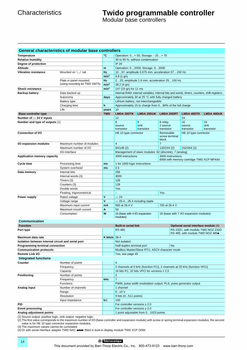
General characteristics of modular base controllersTemperature °C Operation: 0…+ 55; Storage: - 25…+ 70Relative humidity 30 to 95 %, without condensationDegree of protection IP 20Altitude m Operation: 0…2000; Storage: 0…3000Vibration resistance Mounted on 5 rail Hz 10…57, amplitude 0.075 mm, acceleration 57…150 Hz
m/s2 9.8 (1 gn)Plate or panel mounted (using mounting kit TWD XMT5)
Hz 2…25, amplitude 1.6 mm, acceleration 25…100 Hzm/s2 39.2 (4 gn)
Shock resistance m/s2 147 (15 gn) for 11 msBackup battery Data backed up Internal RAM: internal variables, internal bits and words, timers, counters, shift registers...
Autonomy days Approximately 30 at 25 °C with fully charged batteryBattery type Lithium battery, not interchangeableCharging time h Approximately 15 to charge from 0…90% of the full chargeLife years 10
Base controller type TWD LMDA 20DTK LMDA 20DUK LMDA 20DRT LMDA 40DTK LMDA 40DUKNumber of c 24 V inputs 12 24Number and type of outputs (1) 8
source transistor
8 sink transistor
6 relay,2 source transistor
16source transistor
16 sink transistor
Connection of I/O HE 10 type connector Removable screw terminal block
HE 10 type connector
I/O expansion modules Maximum number of modules 4 7Maximum number of I/O 84/148 (2) 132/244 (2) 152/264 (2)AS-Interface Management of slave modules: 62 (discrete), 7 (analog)
Application memory capacity 3000 instructions 3000 instructions,6000 with memory cartridge TWD XCP MFK64
Cycle time Processing time ms 1 for 1000 logic instructionsSystem overhead ms 0.5
Data memory Internal bits 256Internal words (3) 3000Timers (3) 128Counters (3) 128Double words YesFloating, trigonometrical – Yes
Power supply Rated voltage V c 24Voltage range V c 20.4…26.4 including rippleMaximum input current mA 560 at 26.4 V 700 at 26.4 VMaximum inrush current A 50Consumption W 15 (base with 4 I/O expansion
modules)19 (base with 7 I/O expansion modules)
CommunicationFunction Built-in serial link Optional serial interface module (4)
Port type RS 485 RS 232C, with module TWD NOZ 232DRS 485, with module TWD NOZ 485p
Maximum data rate K bits/s 38.4Isolation between internal circuit and serial port Not isolatedProgramming terminal connection Half-duplex terminal port NoCommunication protocols Modbus Master/Slave RTU. ASCII character modeRemote Link I/O Yes, see page 45
Integrated functionsCounter Number of points 4
Frequency 2 channels at 5 kHz (function FCi), 2 channels at 20 kHz (function VFCi)Capacity 16 bits FC, 32 bits VFCi for versions u 2.5
Positioning Number of points 2Frequency kHz 7Functions PWM, pulse width modulation output; PLS, pulse generator output
Analog input Number of channels 1 channelRange 0...10 VResolution 9 bits (0...511 points)Input impedance kΩ 100
PID For controller versions ≥ 2.0Event processing For controller versions ≥ 2.0Analog adjustment points 1 point adjustable from 0…1023 points(1) Source output: positive logic, sink output: negative logic.(2) The first value corresponds to the maximum number of I/O (base controller and expansion module) with screw or spring terminal expansion modules, the second
value is for HE 10 type connector expansion modules.(3) The maximum values cannot be cumulated.(4) Or with serial interface adapter TWD NAC pppp fitted in built-in display module TWD XCP ODM.
14This document provided by Barr-Thorp Electric Co., Inc. 800-473-9123 www.barr-thorp.com
Characteristics (continued) 0 Twido programmable controller 0
Modular base controllers
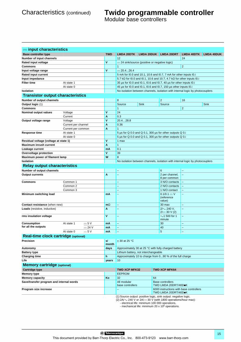
c input characteristics Base controller type TWD LMDA 20DTK LMDA 20DUK LMDA 20DRT LMDA 40DTK LMDA 40DUK
Number of input channels 12 24Rated input voltage V c 24 sink/source (positive or negative logic)Commons 1 2Input voltage range V c 20.4...26.4Rated input current 5 mA for I0.0 and 10.1, 10.6 and I0.7, 7 mA for other inputs I0.iInput impedance 5.7 kΩ for I0.0 and I0.1, 10.6 and 10.7, 4.7 kΩ for other inputs I0.iFilter time At state 1 35 µs for I0.0 and I0.1, I0.6 and I0.7, 40 µs for other inputs I0.i
At state 0 45 µs for I0.0 and I0.1, I0.6 and I0.7, 150 µs other inputs I0.iIsolation No isolation between channels, isolation with internal logic by photocouplers
Transistor output characteristicsNumber of output channels 8 2 16Output logic (1) Source Sink Source SinkCommons 1 2Nominal output values Voltage V 24
Current A 0.3Output voltage range Voltage V 20.4…28.8
Current per channel A 0.36Current per common A 1
Response time At state 1 5 µs for Q 0.0 and Q 0.1, 300 µs for other outputs Q 0.iAt state 0 5 µs for Q 0.0 and Q 0.1, 300 µs for other outputs Q 0.i
Residual voltage (voltage at state 1) V 1 maxMaximum inrush current A 1Leakage current mA 0.1Overvoltage protection V 39Maximum power of filament lamp W 8Isolation No isolation between channels, isolation with internal logic by photocouplers
Relay output characteristicsNumber of output channels – 6 –Output currents A – 2 per channel,
8 per common–
Commons Common 1 – 3 N/O contacts –Common 2 – 2 N/O contacts –Common 3 – 1 N/O contact –
Minimum switching load mA – 0.1/0.1 c V (reference value)
–
Contact resistance (when new) mΩ – 30 max –Loads (resistive, inductive) A – 2/a 240 V,
2/c 30 V (2)–
rms insulation voltage V – a1 500 for 1 minute
–
Consumption for all the outputs
At state 1 c 5 V mA – 30 –c 24 V mA – 40 –
At state 0 c 5 V mA – 5 –
Real-time clock cartridge (optional)
Precision s/month
+ 30 at 25 °C
Autonomy days Approximately 30 at 25 °C with fully charged batteryBattery type Lithium battery, not interchangeableCharging time h Approximately 10 to charge from 0...90 % of the full chargeLife years 10
Memory cartridge (optional)
Cartridge type TWD XCP MFK32 TWD XCP MFK64Memory type EEPROMMemory capacity Ko 32 64Save/transfer program and internal words All modular
base controllersBase controllers TWD LMDA 20DRT/40DpK
Program size increase – 6000 instructions with base controllersTWD LMDA 20DRT/40DpK
(1) Source output: positive logic, sink output: negative logic.(2) 2A/a 240 V or 2A/c 30 V (with 1800 operations/hour max):
- electrical life: minimum 100 000 operations,- mechanical life: minimum 20 x 106 operations.
15This document provided by Barr-Thorp Electric Co., Inc. 800-473-9123 www.barr-thorp.com
References 0 Twido programmable controller 0
Modular base controllers
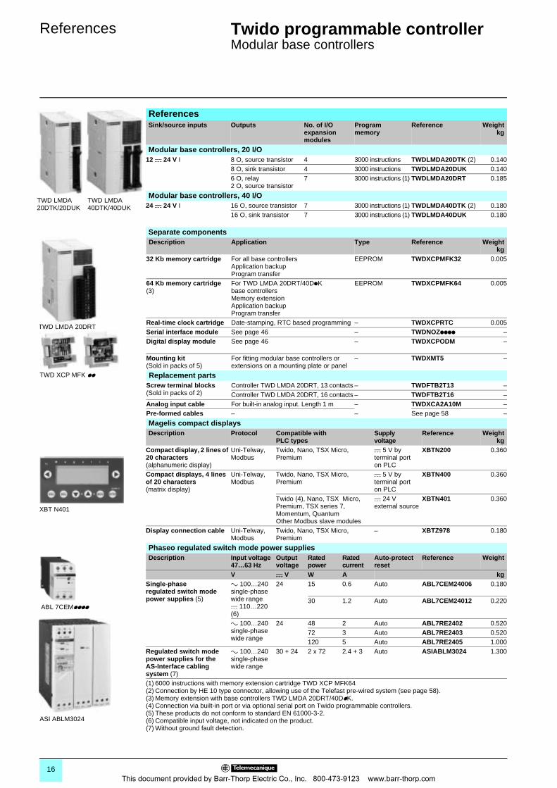
ReferencesSink/source inputs Outputs No. of I/O
expansion modules
Programmemory
Reference Weightkg
Modular base controllers, 20 I/O12 c 24 V I 8 O, source transistor 4 3000 instructions TWDLMDA20DTK (2) 0.140
8 O, sink transistor 4 3000 instructions TWDLMDA20DUK 0.1406 O, relay2 O, source transistor
7 3000 instructions (1) TWDLMDA20DRT 0.185
Modular base controllers, 40 I/O24 c 24 V I 16 O, source transistor 7 3000 instructions (1) TWDLMDA40DTK (2) 0.180
16 O, sink transistor 7 3000 instructions (1) TWDLMDA40DUK 0.180
Separate components Description Application Type Reference Weight
kg32 Kb memory cartridge For all base controllers
Application backupProgram transfer
EEPROM TWDXCPMFK32 0.005
64 Kb memory cartridge(3)
For TWD LMDA 20DRT/40DpK base controllersMemory extensionApplication backupProgram transfer
EEPROM TWDXCPMFK64 0.005
Real-time clock cartridge Date-stamping, RTC based programming – TWDXCPRTC 0.005Serial interface module See page 46 – TWDNOZpppp –Digital display module See page 46 – TWDXCPODM –
Mounting kit(Sold in packs of 5)
For fitting modular base controllers or extensions on a mounting plate or panel
– TWDXMT5 –
Replacement partsScrew terminal blocks(Sold in packs of 2)
Controller TWD LMDA 20DRT, 13 contacts – TWDFTB2T13 –Controller TWD LMDA 20DRT, 16 contacts – TWDFTB2T16 –
Analog input cable For built-in analog input. Length 1 m – TWDXCA2A10M –Pre-formed cables – – See page 58 –
Magelis compact displaysDescription Protocol Compatible with
PLC typesSupply voltage
Reference Weightkg
Compact display, 2 lines of 20 characters(alphanumeric display)
Uni-Telway, Modbus
Twido, Nano, TSX Micro, Premium
c 5 V by terminal port on PLC
XBTN200 0.360
Compact displays, 4 lines of 20 characters(matrix display)
Uni-Telway, Modbus
Twido, Nano, TSX Micro, Premium
c 5 V by terminal port on PLC
XBTN400 0.360
Twido (4), Nano, TSX Micro, Premium, TSX series 7, Momentum, Quantum Other Modbus slave modules
c 24 V external source
XBTN401 0.360
Display connection cable Uni-Telway, Modbus
Twido, Nano, TSX Micro, Premium
– XBTZ978 0.180
Phaseo regulated switch mode power suppliesDescription Input voltage
47…63 Hz Output voltage
Rated power
Rated current
Auto-protect reset
Reference Weight
V c V W A kgSingle-phaseregulated switch mode power supplies (5)
a 100…240 single-phase wide range c 110…220 (6)
24 15 0.6 Auto ABL7CEM24006 0.180
30 1.2 Auto ABL7CEM24012 0.220
a 100…240 single-phase wide range
24 48 2 Auto ABL7RE2402 0.52072 3 Auto ABL7RE2403 0.520120 5 Auto ABL7RE2405 1.000
Regulated switch mode power supplies for the AS-Interface cabling system (7)
a 100…240 single-phase wide range
30 + 24 2 x 72 2.4 + 3 Auto ASIABLM3024 1.300
(1) 6000 instructions with memory extension cartridge TWD XCP MFK64(2) Connection by HE 10 type connector, allowing use of the Telefast pre-wired system (see page 58).(3) Memory extension with base controllers TWD LMDA 20DRT/40DpK.(4) Connection via built-in port or via optional serial port on Twido programmable controllers.(5) These products do not conform to standard EN 61000-3-2.(6) Compatible input voltage, not indicated on the product.(7) Without ground fault detection.
TWD LMDA20DTK/20DUK
TWD LMDA40DTK/40DUK
TWD LMDA 20DRT
TWD XCP MFK pp
XBT N401
ABL 7CEMpppp
ASI ABLM3024
16This document provided by Barr-Thorp Electric Co., Inc. 800-473-9123 www.barr-thorp.com
Dimensions,connections 0
Twido programmable controller 0
Modular base controllers
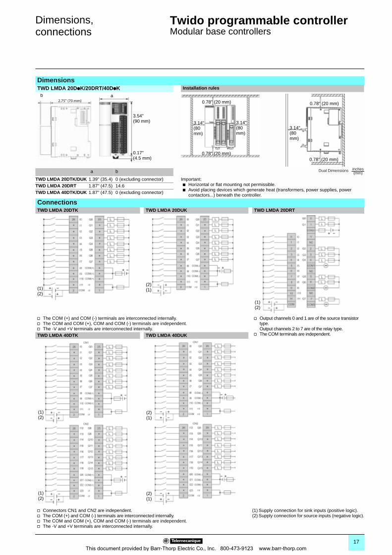
DimensionsTWD LMDA 20DpK/20DRT/40DpK Installation rules
a b
TWD LMDA 20DTK/DUK 1.39" (35.4) 0 (excluding connector) Important:b Horizontal or flat mounting not permissible.b Avoid placing devices which generate heat (transformers, power supplies, power
contactors...) beneath the controller.
TWD LMDA 20DRT 1.87" (47.5) 14.6 TWD LMDA 40DTK/DUK 1.87" (47.5) 0 (excluding connector)
ConnectionsTWD LMDA 20DTK TWD LMDA 20DUK TWD LMDA 20DRT
v The COM (+) and COM (-) terminals are interconnected internally.v The COM and COM (+), COM and COM (-) terminals are independent.v The -V and +V terminals are interconnected internally.
v Output channels 0 and 1 are of the source transistor type.Output channels 2 to 7 are of the relay type.
v The COM terminals are independent.TWD LMDA 40DTK TWD LMDA 40DUK
v Connectors CN1 and CN2 are independent.v The COM (+) and COM (-) terminals are interconnected internally.v The COM and COM (+), COM and COM (-) terminals are independent.v The -V and +V terminals are interconnected internally.
(1) Supply connection for sink inputs (positive logic).(2) Supply connection for source inputs (negative logic).
a
3.54"(90 mm)
0.17"(4.5 mm)
b2.75" (70 mm) 0.78" (20 mm)
0.78" (20 mm)
3.14"(80 mm)
3.14"(80 mm)
0.78" (20 mm)
0.78" (20 mm)
3.14"(80 mm)
Dual Dimensions inches(mm)
(1)(2)
(2)(1)
(1)(2)
(1)(2)
(1)(2)
(2)(1)
(2)(1)
17This document provided by Barr-Thorp Electric Co., Inc. 800-473-9123 www.barr-thorp.com
Selection guide 0 Twido programmable controller 0
Discrete I/O modules
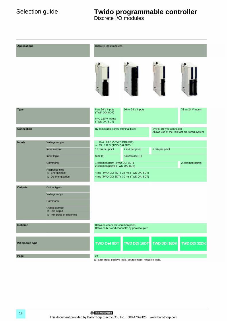
Applications Discrete Input modules
Type 8 c 24 V inputs(TWD DDI 8DT)
8 a 120 V inputs(TWD DAI 8DT)
16 c 24 V inputs 32 c 24 V inputs
Connection By removable screw terminal block By HE 10 type connectorAllows use of the Telefast pre-wired system
Inputs Voltage ranges c 20.4...28.8 V (TWD DDI 8DT)a 85...132 V (TWD DAI 8DT)
Input current 15 mA per point 7 mA per point 5 mA per point
Input logic Sink (1) Sink/source (1)
Commons 1 common point (TWD DDI 8DT)2 common points (TWD DAI 8DT)
2 common points
Response timev Energization 4 ms (TWD DDI 8DT), 25 ms (TWD DAI 8DT)v De-energization 4 ms (TWD DDI 8DT), 30 ms (TWD DAI 8DT)
Outputs Output types
Voltage range
Commons
Output currentv Per outputv Per group of channels
Isolation Between channels: common point, Between bus and channels: by photocoupler
I/O module type TWD DpI 8DT TWD DDI 16DT TWD DDI 16DK TWD DDI 32DK
Page 24(1) Sink input: positive logic, source input: negative logic.
18This document provided by Barr-Thorp Electric Co., Inc. 800-473-9123 www.barr-thorp.com
00
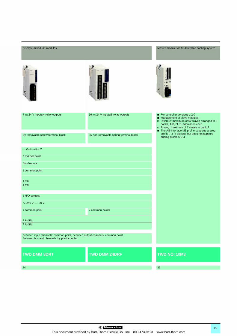
Discrete mixed I/O modules Master module for AS-Interface cabling system
4 c 24 V inputs/4 relay outputs 16 c 24 V inputs/8 relay outputs b For controller versions ≥ 2.0b Management of slave modules:v Discrete: maximum of 62 slaves arranged in 2
banks, A/B, of 31 addresses eachv Analog: maximum of 7 slaves in bank Ab The AS-Interface M3 profile supports analog
profile 7.3 (7 slaves), but does not support analog profile S-7.4
By removable screw terminal block By non-removable spring terminal block
c 20.4...28.8 V
7 mA per point
Sink/source
1 common point
4 ms4 ms
1 N/O contact
a 240 V, c 30 V
1 common point 2 common points
2 A (Ith)7 A (Ith)
Between input channels: common point, between output channels: common pointBetween bus and channels: by photocoupler
TWD DMM 8DRT TWD DMM 24DRF TWD NOI 10M3
24 39
19This document provided by Barr-Thorp Electric Co., Inc. 800-473-9123 www.barr-thorp.com
Selection guide (continued) 0 Twido programmable controller 0
Discrete I/O modules
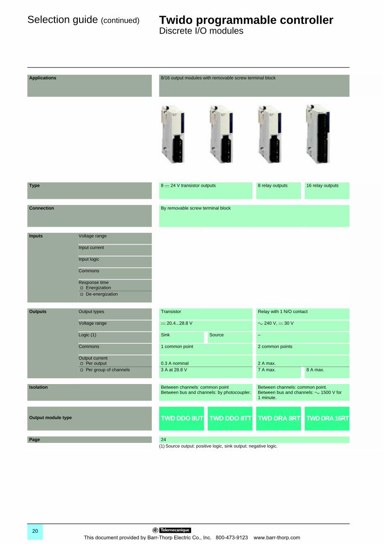
Applications 8/16 output modules with removable screw terminal block
Type 8 c 24 V transistor outputs 8 relay outputs 16 relay outputs
Connection By removable screw terminal block
Inputs Voltage range
Input current
Input logic
Commons
Response timev Energizationv De-energization
Outputs Output types Transistor Relay with 1 N/O contact
Voltage range c 20.4...28.8 V a 240 V, c 30 V
Logic (1) Sink Source –
Commons 1 common point 2 common points
Output currentv Per output 0.3 A nominal 2 A max.v Per group of channels 3 A at 28.8 V 7 A max. 8 A max.
Isolation Between channels: common pointBetween bus and channels: by photocoupler.
Between channels: common point. Between bus and channels: a 1500 V for 1 minute.
Output module type TWD DDO 8UT TWD DDO 8TT TWD DRA 8RT TWD DRA 16RT
Page 24(1) Source output: positive logic, sink output: negative logic.
20This document provided by Barr-Thorp Electric Co., Inc. 800-473-9123 www.barr-thorp.com
00
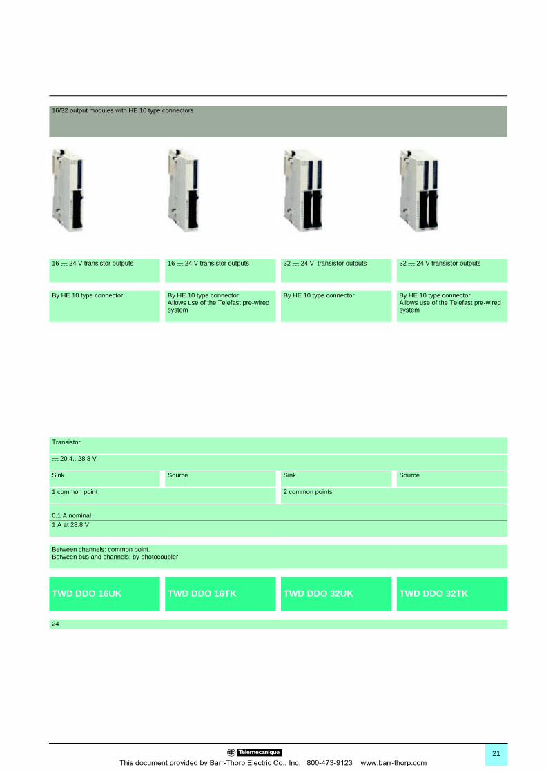
16/32 output modules with HE 10 type connectors
16 c 24 V transistor outputs 16 c 24 V transistor outputs 32 c 24 V transistor outputs 32 c 24 V transistor outputs
By HE 10 type connector By HE 10 type connectorAllows use of the Telefast pre-wired system
By HE 10 type connector By HE 10 type connectorAllows use of the Telefast pre-wired system
Transistor
c 20.4...28.8 V
Sink Source Sink Source
1 common point 2 common points
0.1 A nominal1 A at 28.8 V
Between channels: common point. Between bus and channels: by photocoupler.
TWD DDO 16UK TWD DDO 16TK TWD DDO 32UK TWD DDO 32TK
24
21This document provided by Barr-Thorp Electric Co., Inc. 800-473-9123 www.barr-thorp.com
Presentation,description 0
Twido programmable controller 0
Discrete I/O modules
The range of Twido I/O modules includes input modules, output modules and mixed input/output modules. With the 15 I/O modules offered, in addition to the I/O integrated in 24 I/O compact base controllers and modular base controllers, configurations can be adapted to best suit application requirements, so optimizing costs. The following discrete I/O modules are available:
b 1 a 120 V discrete input module, 8 channels, fitted with a removable screw terminal block
b 4 c 24 V discrete input modules comprising an 8-channel module, two 16-channel modules and a 32-channel module, equipped with either removable screw terminal blocks or HE 10 type connector, depending on the model. These modules can be either “sink or source”.
b 8 discrete output modules comprising two output modules with 8 and 16 relay outputs, three output modules with 8, 16 or 32-channel “sink” transistor outputs and three output modules with 8, 16 or 32-channel “source” transistor outputs, equipped with either removable screw terminal blocks or HE 10 type connector, depending on the model
b 2 discrete mixed input and output modules, comprising one 4-channel input/4-channel relay output module with removable screw terminal block and one 16-channel input/8-channel relay output module with non-removable spring terminal block
The narrow width of these I/O modules (17.5 mm, 23.5 mm, 29.7 mm or 39.1 mm) makes it possible to build Twido configurations of up to 264 I/O with a minimal overall size of L 10.0” (255.4 mm) x H 3.54” (90 mm) x D 3.2” (81.3 mm).
All these discrete I/O modules and the analog I/O modules are connected to the base controller by stacking them on a 5 rail, starting from the right-hand side panel of the base controller, according to the following rules: b For 24 I/O compact base controllers TWD LCpA 24DRF: 4 modules max. (see characteristics page 6b For 40 I/O compact base controllers TWD LCAp 40DRF: 7 modules max. (see characteristics page 6)b For 20 I/O modular base controllers TWD LMDA 20DpK: 4 modules max. (see characteristics page 15)b For 20 and 40 I/O base controllers TWD LMDA 20DRT/40DpK: 7 modules max. (see characteristics page 15)
All the discrete I/O modules are electrically isolated with the use of a photocoupler between the internal electronic circuit and the input/output channels.
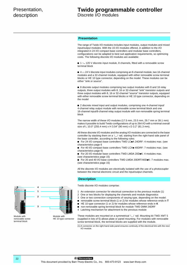
Twido discrete I/O modules comprise:
1 An extension connector for electrical connection to the previous module (1)2 One or two blocks for displaying the channels and module diagnostics3 One or two connection components of varying type, depending on the model:b removable screw terminal block (1 or 2) for modules whose reference ends in Tb HE 10 type connector (1 or 2) for modules whose reference ends in Kb non-removable spring terminal block for module TWD DMM 24DRF4 Latching mechanism for attachment to the previous module
These modules are mounted on a symmetrical 5 rail. Mounting kit TWD XMT 5 (supplied in lots of 5) allows plate or panel mounting. For modules with removable screw terminal block, the terminal blocks are supplied with the module.
(1) A connector on the right-hand side panel ensures continuity of the electrical link with the next I/O module.
Presentation
Description
1
2
3
Module withHE 10 type connector
Module with removable screw terminal block
4
22This document provided by Barr-Thorp Electric Co., Inc. 800-473-9123 www.barr-thorp.com
Characteristics 0 Twido programmable controller 0
Discrete I/O modules
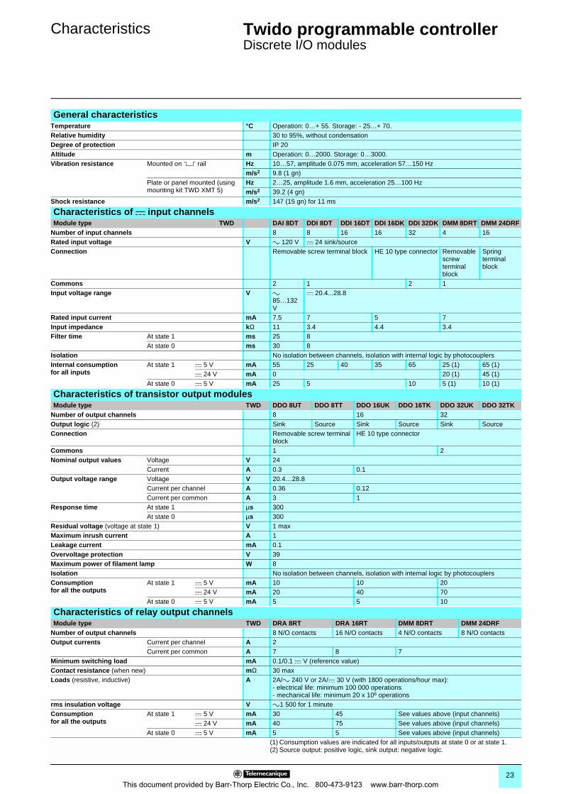
General characteristicsTemperature °C Operation: 0…+ 55. Storage: - 25…+ 70.Relative humidity 30 to 95%, without condensationDegree of protection IP 20Altitude m Operation: 0…2000. Storage: 0…3000.Vibration resistance Mounted on 5 rail Hz 10…57, amplitude 0.075 mm, acceleration 57…150 Hz
m/s2 9.8 (1 gn)Plate or panel mounted (using mounting kit TWD XMT 5)
Hz 2…25, amplitude 1.6 mm, acceleration 25…100 Hzm/s2 39.2 (4 gn)
Shock resistance m/s2 147 (15 gn) for 11 ms
Characteristics of c input channels Module type TWD DAI 8DT DDI 8DT DDI 16DT DDI 16DK DDI 32DK DMM 8DRT DMM 24DRF
Number of input channels 8 8 16 16 32 4 16Rated input voltage V a 120 V c 24 sink/sourceConnection Removable screw terminal block HE 10 type connector Removable
screw terminal block
Spring terminalblock
Commons 2 1 2 1Input voltage range V a
85…132 V
c 20.4...28.8
Rated input current mA 7.5 7 5 7Input impedance kΩ 11 3.4 4.4 3.4Filter time At state 1 ms 25 8
At state 0 ms 30 8Isolation No isolation between channels, isolation with internal logic by photocouplers Internal consumptionfor all inputs
At state 1 c 5 V mA 55 25 40 35 65 25 (1) 65 (1)c 24 V mA 0 20 (1) 45 (1)
At state 0 c 5 V mA 25 5 10 5 (1) 10 (1)
Characteristics of transistor output modulesModule type TWD DDO 8UT DDO 8TT DDO 16UK DDO 16TK DDO 32UK DDO 32TK
Number of output channels 8 16 32Output logic (2) Sink Source Sink Source Sink SourceConnection Removable screw terminal
blockHE 10 type connector
Commons 1 2Nominal output values Voltage V 24
Current A 0.3 0.1Output voltage range Voltage V 20.4…28.8
Current per channel A 0.36 0.12Current per common A 3 1
Response time At state 1 µs 300 At state 0 µs 300
Residual voltage (voltage at state 1) V 1 maxMaximum inrush current A 1Leakage current mA 0.1Overvoltage protection V 39Maximum power of filament lamp W 8Isolation No isolation between channels, isolation with internal logic by photocouplersConsumptionfor all the outputs
At state 1 c 5 V mA 10 10 20c 24 V mA 20 40 70
At state 0 c 5 V mA 5 5 10
Characteristics of relay output channelsModule type TWD DRA 8RT DRA 16RT DMM 8DRT DMM 24DRF
Number of output channels 8 N/O contacts 16 N/O contacts 4 N/O contacts 8 N/O contactsOutput currents Current per channel A 2
Current per common A 7 8 7Minimum switching load mA 0.1/0.1 c V (reference value)Contact resistance (when new) mΩ 30 maxLoads (resistive, inductive) A 2A/a 240 V or 2A/c 30 V (with 1800 operations/hour max):
- electrical life: minimum 100 000 operations- mechanical life: minimum 20 x 106 operations
rms insulation voltage V a1 500 for 1 minuteConsumptionfor all the outputs
At state 1 c 5 V mA 30 45 See values above (input channels)c 24 V mA 40 75 See values above (input channels)
At state 0 c 5 V mA 5 5 See values above (input channels)(1) Consumption values are indicated for all inputs/outputs at state 0 or at state 1.(2) Source output: positive logic, sink output: negative logic.
23This document provided by Barr-Thorp Electric Co., Inc. 800-473-9123 www.barr-thorp.com
References0
Twido programmable controller 0
Discrete I/O modules
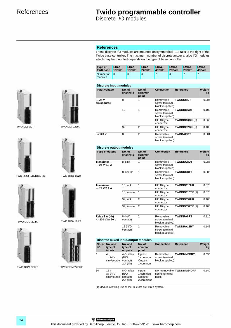
These discrete I/O modules are mounted on symmetrical 5 rails to the right of the Twido base controller. The maximum number of discrete and/or analog I/O modules which may be mounted depends on the type of base controller:
References
Type of TWD base
LCpA 10DRF
LCpA 16DRF
LCpA 24DRF
LCAp 40DRF
LMDA 20DpK
LMDA 20DRT
LMDA 40DpK
Number of modules
0 0 4 7 4 7 7
TWD DDI 8DT TWD DDI 32DK
TWD DDO 16pKTWD DDO 8pT/DRA 8RT
TWD DRA 16RTTWD DDO 32pK
TWD DDM 8DRT TWD DDM 24DRF
Discrete input modulesInput voltage No. of
channelsNo. of common point
Connection Reference Weightkg
c 24 V sink/source
8 1 Removable screw terminal block (supplied)
TWDDDI8DT 0.085
16 1 Removable screw terminal block (supplied)
TWDDDI16DT 0.100
HE 10 type connector
TWDDDI16DK (1) 0.065
32 2 HE 10 type connector
TWDDDI32DK (1) 0.100
a 120 V 8 2 Removable screw terminal block (supplied)
TWDDAI8DT 0.081
Discrete output modulesType of output No. of
channelsNo. of common point
Connection Reference Weightkg
Transistor c 24 V/0.3 A
8, sink 1 Removable screw terminal block (supplied)
TWDDDO8UT 0.085
8, source 1 Removable screw terminal block (supplied)
TWDDDO8TT 0.085
Transistor c 24 V/0.1 A
16, sink 1 HE 10 type connector
TWDDDO16UK 0.070
16, source 1 HE 10 type connector
TWDDDO16TK (1) 0.070
32, sink 2 HE 10 type connector
TWDDDO32UK 0.105
32, source 2 HE 10 type connector
TWDDDO32TK (1) 0.105
Relay 2 A (Ith)a 230 V/c 30 V
8 (N/O contact)
2 Removable screw terminal block (supplied)
TWDDRA8RT 0.110
16 (N/O contact)
2 Removable screw terminal block (supplied)
TWDDRA16RT 0.145
Discrete mixed input/output modulesNo. of I/O
No. and type of inputs
No. and type of outputs
No. of common point
Connection Reference Weightkg
8 4 I, c 24 Vsink/source
4 O, relay(N/O contact)2 A (Ith)
Inputs: 1 commonOutputs: 1 common
Removable screw terminal block (supplied)
TWDDMM8DRT 0.095
24 16 I, c 24 Vsink/source
8 O, relay(N/O contact)2 A (Ith)
Inputs: 1 commonOutputs: 2 commons
Non-removable spring terminal block
TWDDMM24DRF 0.140
(1) Module allowing use of the Telefast pre-wired system.
24This document provided by Barr-Thorp Electric Co., Inc. 800-473-9123 www.barr-thorp.com
References (continued) 0 Twido programmable controller 0
Discrete I/O modules
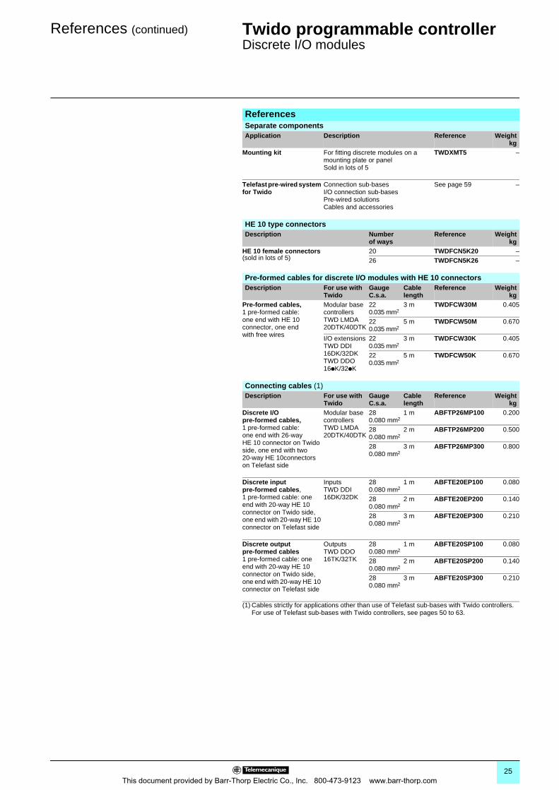
(1) Cables strictly for applications other than use of Telefast sub-bases with Twido controllers. For use of Telefast sub-bases with Twido controllers, see pages 50 to 63.
ReferencesSeparate componentsApplication Description Reference Weight
kgMounting kit For fitting discrete modules on a
mounting plate or panelSold in lots of 5
TWDXMT5 –
Telefast pre-wired system for Twido
Connection sub-basesI/O connection sub-basesPre-wired solutionsCables and accessories
See page 59 –
HE 10 type connectorsDescription Number
of waysReference Weight
kgHE 10 female connectors(sold in lots of 5)
20 TWDFCN5K20 –26 TWDFCN5K26 –
Pre-formed cables for discrete I/O modules with HE 10 connectorsDescription For use with
TwidoGaugeC.s.a.
Cable length
Reference Weightkg
Pre-formed cables,1 pre-formed cable: one end with HE 10 connector, one end with free wires
Modular base controllers TWD LMDA20DTK/40DTK
220.035 mm2
3 m TWDFCW30M 0.405
220.035 mm2
5 m TWDFCW50M 0.670
I/O extensions TWD DDI 16DK/32DK TWD DDO 16pK/32pK
220.035 mm2
3 m TWDFCW30K 0.405
220.035 mm2
5 m TWDFCW50K 0.670
Connecting cables (1)Description For use with
TwidoGaugeC.s.a.
Cable length
Reference Weightkg
Discrete I/O pre-formed cables,1 pre-formed cable: one end with 26-way HE 10 connector on Twido side, one end with two 20-way HE 10connectors on Telefast side
Modular base controllers TWD LMDA20DTK/40DTK
280.080 mm2
1 m ABFTP26MP100 0.200
280.080 mm2
2 m ABFTP26MP200 0.500
280.080 mm2
3 m ABFTP26MP300 0.800
Discrete input pre-formed cables,1 pre-formed cable: one end with 20-way HE 10 connector on Twido side, one end with 20-way HE 10 connector on Telefast side
InputsTWD DDI 16DK/32DK
280.080 mm2
1 m ABFTE20EP100 0.080
280.080 mm2
2 m ABFTE20EP200 0.140
280.080 mm2
3 m ABFTE20EP300 0.210
Discrete output pre-formed cables1 pre-formed cable: one end with 20-way HE 10 connector on Twido side, one end with 20-way HE 10 connector on Telefast side
Outputs TWD DDO 16TK/32TK
280.080 mm2
1 m ABFTE20SP100 0.080
280.080 mm2
2 m ABFTE20SP200 0.140
280.080 mm2
3 m ABFTE20SP300 0.210
25This document provided by Barr-Thorp Electric Co., Inc. 800-473-9123 www.barr-thorp.com
Dimensions,connections 0
Twido programmable controller 0
Discrete I/O modules
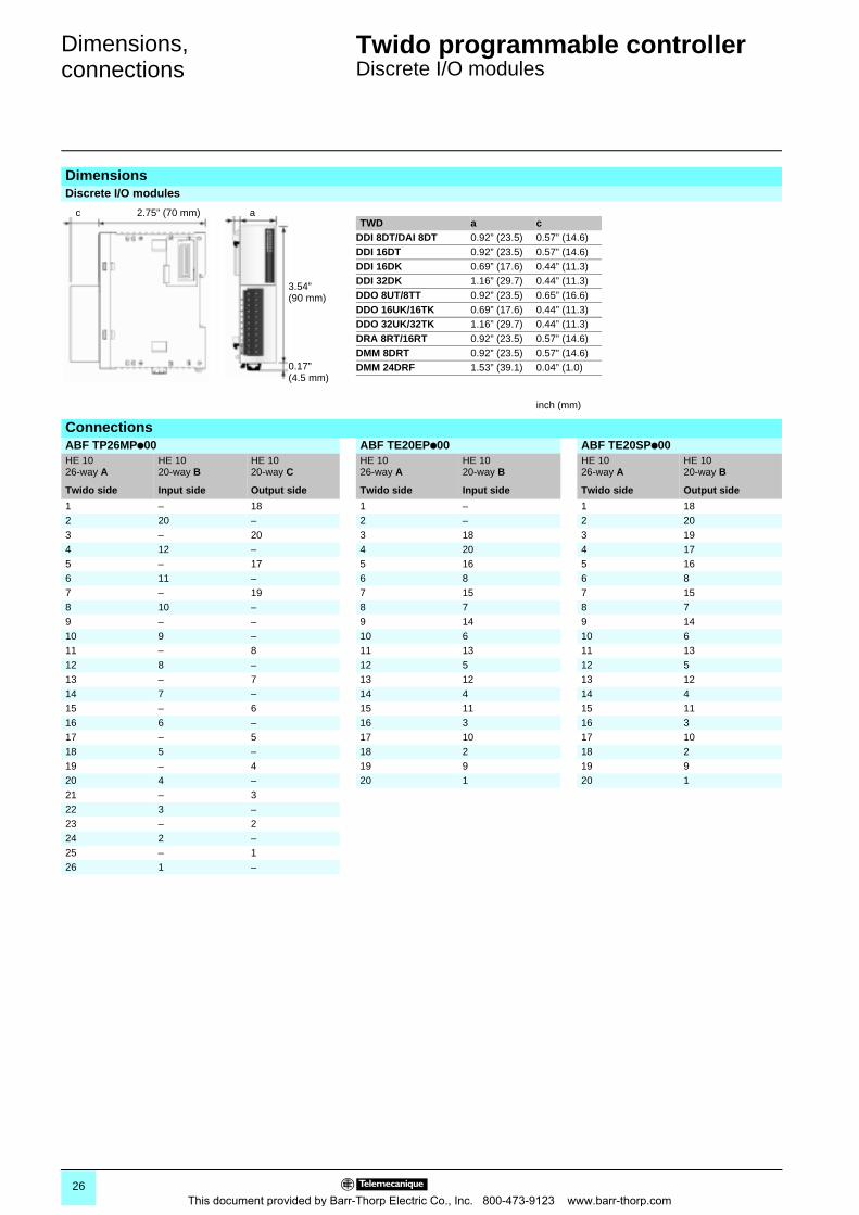
DimensionsDiscrete I/O modules
TWD a cDDI 8DT/DAI 8DT 0.92” (23.5) 0.57” (14.6)DDI 16DT 0.92” (23.5) 0.57” (14.6)DDI 16DK 0.69” (17.6) 0.44” (11.3)DDI 32DK 1.16” (29.7) 0.44” (11.3)DDO 8UT/8TT 0.92” (23.5) 0.65” (16.6)DDO 16UK/16TK 0.69” (17.6) 0.44” (11.3)DDO 32UK/32TK 1.16” (29.7) 0.44” (11.3)DRA 8RT/16RT 0.92” (23.5) 0.57” (14.6)DMM 8DRT 0.92” (23.5) 0.57” (14.6)DMM 24DRF 1.53” (39.1) 0.04” (1.0)
inch (mm)
ConnectionsABF TP26MPp00 ABF TE20EPp00 ABF TE20SPp00HE 10 26-way A
HE 1020-way B
HE 1020-way C
HE 1026-way A
HE 1020-way B
HE 1026-way A
HE 1020-way B
Twido side Input side Output side Twido side Input side Twido side Output side
1 – 18 1 – 1 182 20 – 2 – 2 203 – 20 3 18 3 194 12 – 4 20 4 175 – 17 5 16 5 166 11 – 6 8 6 87 – 19 7 15 7 158 10 – 8 7 8 79 – – 9 14 9 1410 9 – 10 6 10 611 – 8 11 13 11 1312 8 – 12 5 12 513 – 7 13 12 13 1214 7 – 14 4 14 415 – 6 15 11 15 1116 6 – 16 3 16 317 – 5 17 10 17 1018 5 – 18 2 18 219 – 4 19 9 19 920 4 – 20 1 20 121 – 322 3 –23 – 224 2 –25 – 126 1 –
c 2.75” (70 mm) a
0.17” (4.5 mm)
3.54”(90 mm)
26This document provided by Barr-Thorp Electric Co., Inc. 800-473-9123 www.barr-thorp.com
Connections (continued) 0 Twido programmable controller 0
Discrete I/O modules
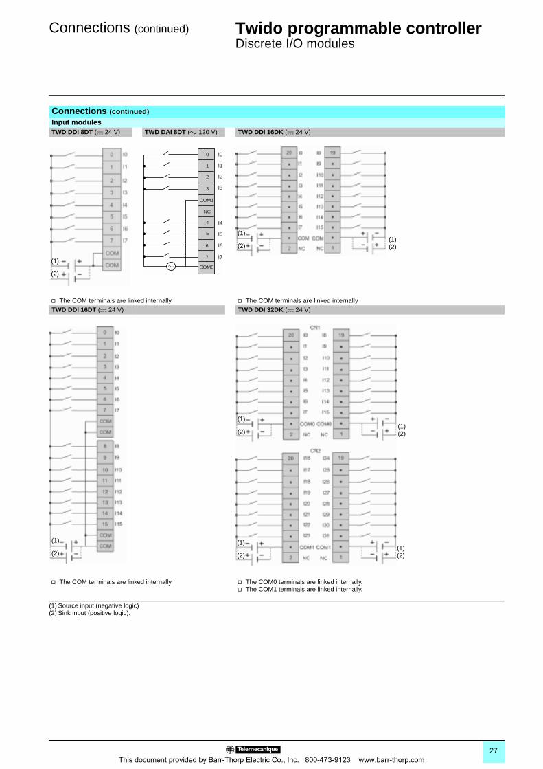
Connections (continued)Input modulesTWD DDI 8DT (c 24 V) TWD DAI 8DT (a 120 V) TWD DDI 16DK (c 24 V)
v The COM terminals are linked internally v The COM terminals are linked internallyTWD DDI 16DT (c 24 V) TWD DDI 32DK (c 24 V)
v The COM terminals are linked internally v The COM0 terminals are linked internally.v The COM1 terminals are linked internally.
(1) Source input (negative logic)(2) Sink input (positive logic).
(1)
(2)
0 I0
I1
I2
I3
I4
I5
I6
I7
1
2
3
COM1
NC
4
5
7
6
COM0a
(1)(2)
(1)
(2)
(1)
(2)(1)(2)
(1)
(2)(1)(2)
(1)
(2)
27This document provided by Barr-Thorp Electric Co., Inc. 800-473-9123 www.barr-thorp.com
Connections (continued) 0 Twido programmable controller 0
Discrete I/O modules
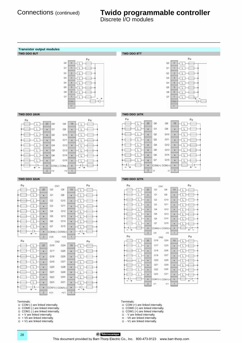
Transistor output modulesTWD DDO 8UT TWD DDO 8TT
TWD DDO 16UK TWD DDO 16TK
TWD DDO 32UK TWD DDO 32TK
Terminals:v COM (-) are linked internally.v COM0 (-) are linked internally.v COM1 (-) are linked internally.v + V are linked internally.v + V0 are linked internally.v + V1 are linked internally.
Terminals: v COM (+) are linked internally.v COM0 (+) are linked internally.v COM1 (+) are linked internally.v - V are linked internally.v - V0 are linked internally.v - V1 are linked internally.
Fu Fu
Fu Fu FuFu
FuFu
Fu Fu
FuFu
Fu Fu
28This document provided by Barr-Thorp Electric Co., Inc. 800-473-9123 www.barr-thorp.com
Connections (continued) 0 Twido programmable controller 0
Discrete I/O modules
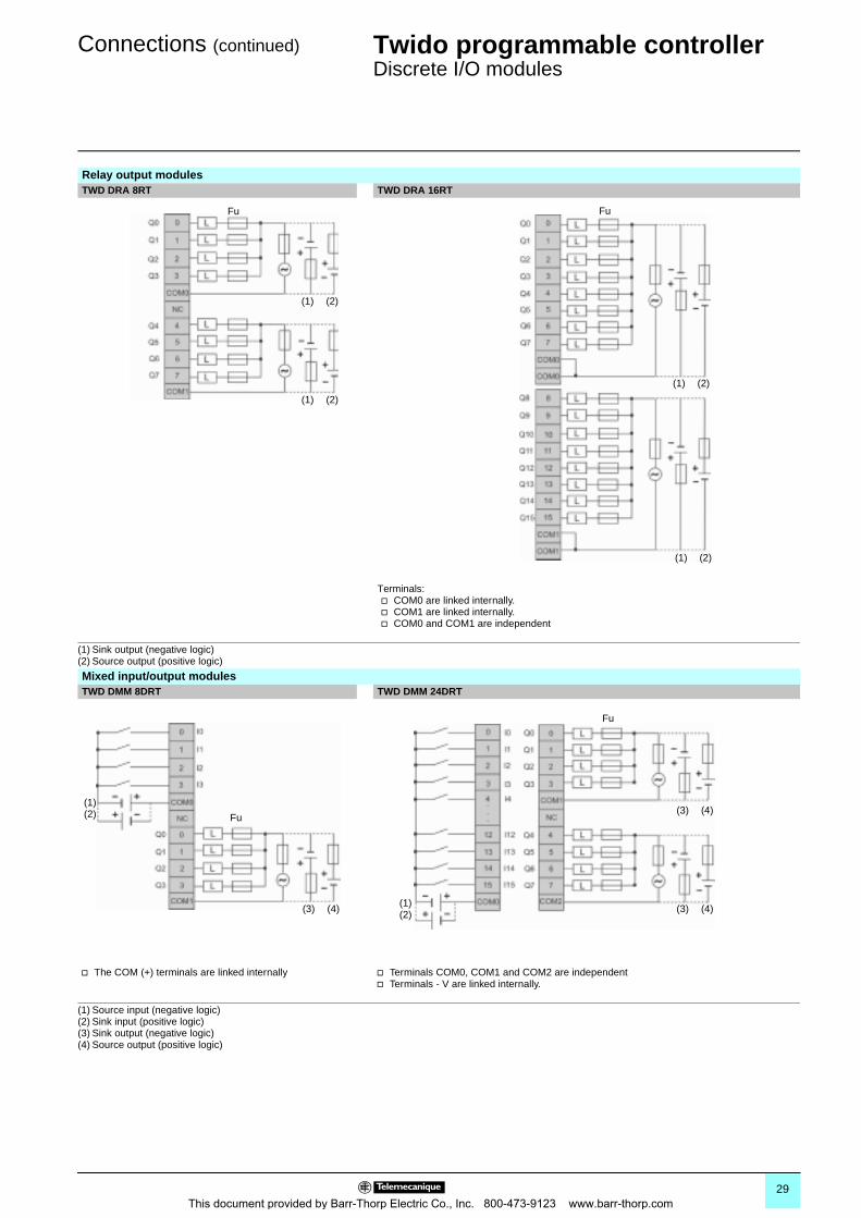
Relay output modulesTWD DRA 8RT TWD DRA 16RT
Terminals: v COM0 are linked internally.v COM1 are linked internally.v COM0 and COM1 are independent
(1) Sink output (negative logic)(2) Source output (positive logic)
Mixed input/output modulesTWD DMM 8DRT TWD DMM 24DRT
v The COM (+) terminals are linked internally v Terminals COM0, COM1 and COM2 are independentv Terminals - V are linked internally.
(1) Source input (negative logic)(2) Sink input (positive logic)(3) Sink output (negative logic)(4) Source output (positive logic)
(1) (2)
(1) (2)
Fu
(1) (2)
(1) (2)
Fu
(3) (4)
Fu
(1)(2) (3) (4)
(3) (4)
Fu
(1)(2)
29This document provided by Barr-Thorp Electric Co., Inc. 800-473-9123 www.barr-thorp.com
Selection guide 0 Twido programmable controller 0
Analog I/O modules
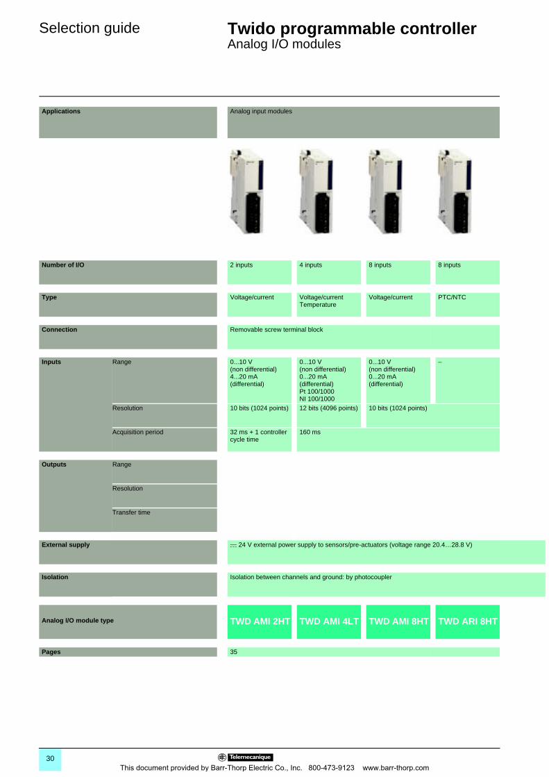
Applications Analog input modules
Number of I/O 2 inputs 4 inputs 8 inputs 8 inputs
Type Voltage/current Voltage/currentTemperature
Voltage/current PTC/NTC
Connection Removable screw terminal block
Inputs Range 0...10 V(non differential)4...20 mA (differential)
0...10 V (non differential)0...20 mA (differential)Pt 100/1000NI 100/1000
0...10 V (non differential)0...20 mA (differential)
–
Resolution 10 bits (1024 points) 12 bits (4096 points) 10 bits (1024 points)
Acquisition period 32 ms + 1 controller cycle time
160 ms
Outputs Range
Resolution
Transfer time
External supply c 24 V external power supply to sensors/pre-actuators (voltage range 20.4…28.8 V)
Isolation Isolation between channels and ground: by photocoupler
Analog I/O module type TWD AMI 2HT TWD AMI 4LT TWD AMI 8HT TWD ARI 8HT
Pages 35
30This document provided by Barr-Thorp Electric Co., Inc. 800-473-9123 www.barr-thorp.com
00
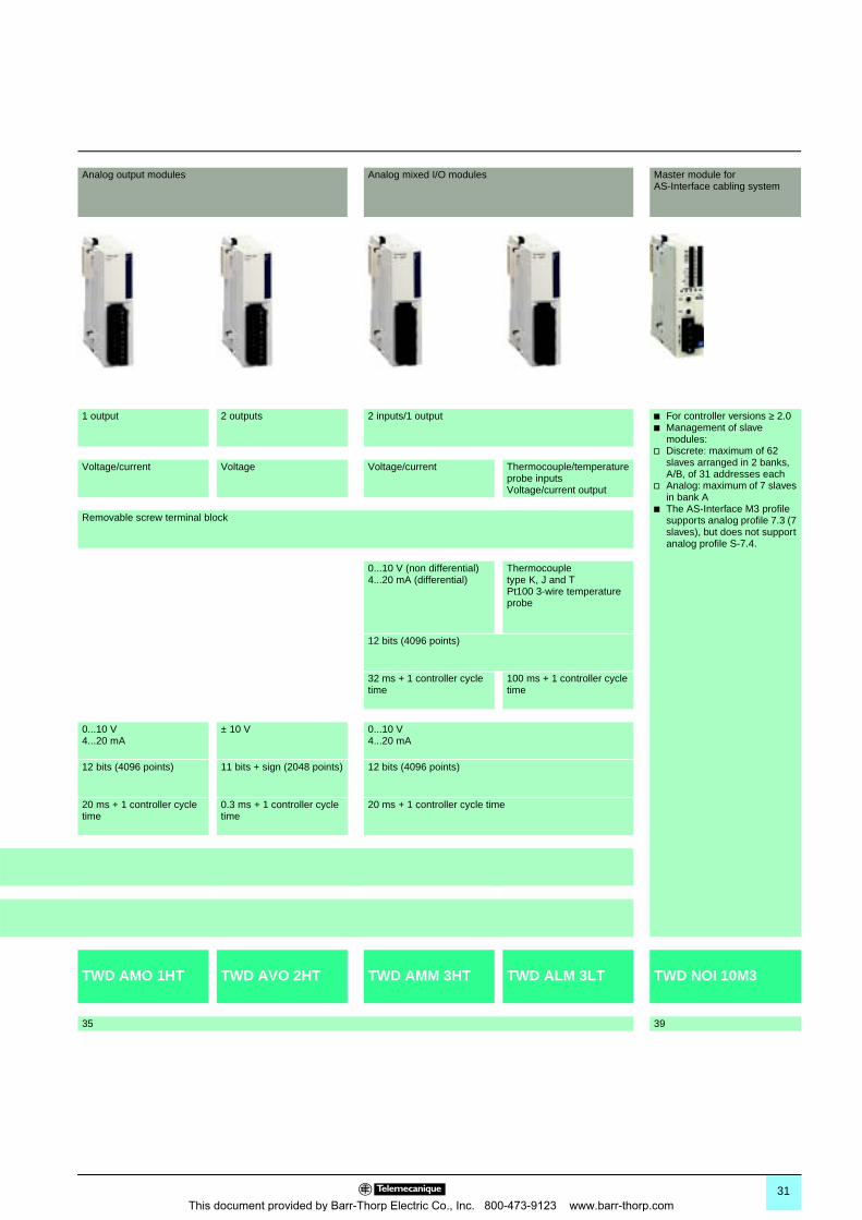
Analog output modules Analog mixed I/O modules Master module for AS-Interface cabling system
1 output 2 outputs 2 inputs/1 output b For controller versions ≥ 2.0b Management of slave
modules:v Discrete: maximum of 62
slaves arranged in 2 banks, A/B, of 31 addresses each
v Analog: maximum of 7 slaves in bank A
b The AS-Interface M3 profile supports analog profile 7.3 (7 slaves), but does not support analog profile S-7.4.
Voltage/current Voltage Voltage/current Thermocouple/temperature probe inputsVoltage/current output
Removable screw terminal block
0...10 V (non differential)4...20 mA (differential)
Thermocoupletype K, J and TPt100 3-wire temperature probe
12 bits (4096 points)
32 ms + 1 controller cycle time
100 ms + 1 controller cycle time
0...10 V4...20 mA
± 10 V 0...10 V4...20 mA
12 bits (4096 points) 11 bits + sign (2048 points) 12 bits (4096 points)
20 ms + 1 controller cycle time
0.3 ms + 1 controller cycle time
20 ms + 1 controller cycle time
TWD AMO 1HT TWD AVO 2HT TWD AMM 3HT TWD ALM 3LT TWD NOI 10M3
35 39
31This document provided by Barr-Thorp Electric Co., Inc. 800-473-9123 www.barr-thorp.com
Presentation,description
Twido programmable controller 0
Analog I/O modules
Twido analog I/O expansion modules enable the acquisition of various analog values encountered in industrial applications.
Analog output modules are used to control the pre-actuators in devices such as variable speed drives, valves and applications that require process control. The output current or voltage is proportional to the numerical value defined by the user program. When the Twido controller stops, the outputs can be configured with fallback (reset to the lowest scale value or hold the last value received). This function, when set to 'hold', is useful when debugging the application or when a fault occurs, in order not to disturb the process being controlled.
The 8 following analog I/O modules are available:
b One module with 2 inputs: 0…10 V, 4…20 mAb One module with 4 inputs: 0…10 V, 0…20 mA, Pt 100/1000, Ni100/1000 range
122 ... 302 °F (50...150 °C)b One module with 8 inputs: 0…10 V, 0…20 mAb One module with 8 inputs: PTC/NTCb One module with 1 output: 0…10 V, 4…20 mAb One module with 2 outputs: ± 10 Vb One mixed module with 2 inputs: 0…10 V, 4…20 mA and 1 output: 0…10 V,
4…20 mAb One mixed module with 2 thermocouple or temperature probe inputs and one
0…10 V, 4…20 mA output
Twido analog extension modules offer a resolution of 10 bits, 11 bits + sign and 12 bits, with connection by removable screw terminal block. An external c 24 V power supply is required for each analog module.
Like discrete I/O modules, analog I/O modules are connected to the base controller by stacking them on a 7 rail, starting from the right-hand side panel of the base controller, according to the following rules:b For 24 I/O compact base controllers TWD LCpA 24DRF: 4 modules max. (see
characteristics page 8)b For 40 I/O compact base controllers TWD LCpA 40DRF: 7 modules max. (see
characteristics page 8)b For 20 I/O modular base controllers TWD LMDA 20DpK: 4 modules max. (see
characteristics page 15)b For 40 I/O modular base controllers TWD LMDA 20DRT/40DpK: 7 modules max.
(see characteristics page 15)
All analog I/O modules are electrically isolated with the use of a photocoupler between the internal electronic circuit and the input/output channels
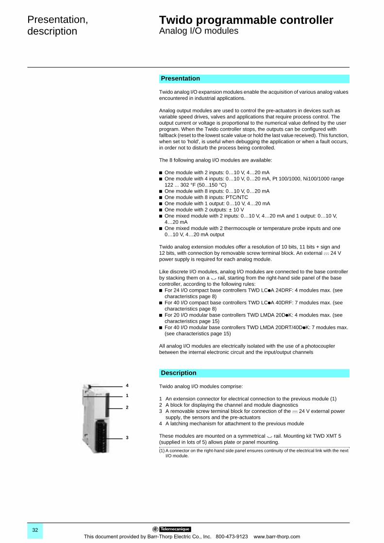
Twido analog I/O modules comprise:
1 An extension connector for electrical connection to the previous module (1)2 A block for displaying the channel and module diagnostics3 A removable screw terminal block for connection of the c 24 V external power
supply, the sensors and the pre-actuators4 A latching mechanism for attachment to the previous module
These modules are mounted on a symmetrical 7 rail. Mounting kit TWD XMT 5 (supplied in lots of 5) allows plate or panel mounting.
(1) A connector on the right-hand side panel ensures continuity of the electrical link with the next I/O module.
Presentation
Description
1
2
3
4
32This document provided by Barr-Thorp Electric Co., Inc. 800-473-9123 www.barr-thorp.com
Characteristics Twido programmable controller 0
Analog I/O modules
General characteristicsTemperature °C Operation: 0…+ 55. Storage: - 25…+ 70.
Relative humidity 30 to 95 %, without condensation
Degree of protection IP 20
Altitude m Operation: 0…2000. Storage: 0…3000.
Vibration resistance Mounted on rail Hz 10…57, amplitude 0.075 mm, acceleration 57…150 Hzm/s2 9.8 (1 gn)
Plate or panel mounted (using mounting kit TWD XMT 5)
Hz 2…25, amplitude 1.6 mm, acceleration 25…100 Hzm/s2 39.2 (4 gn)
Shock resistance m/s2 147 (15 gn) for 11 ms
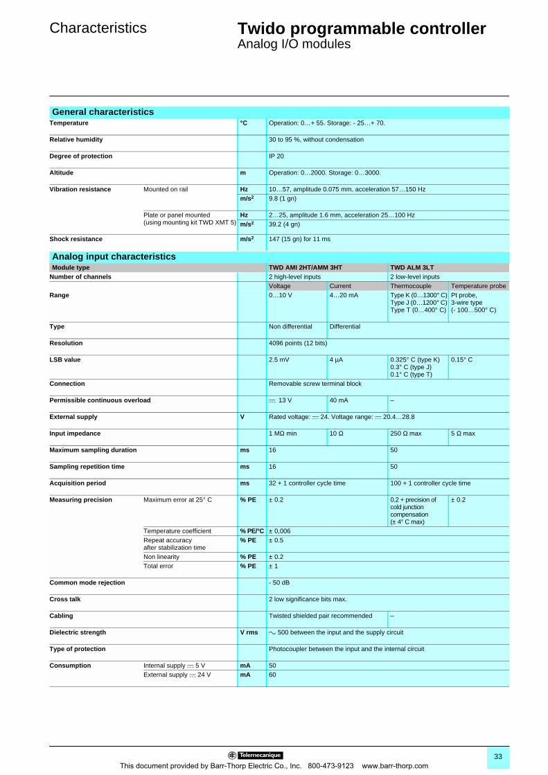
Analog input characteristicsModule type TWD AMI 2HT/AMM 3HT TWD ALM 3LT
Number of channels 2 high-level inputs 2 low-level inputsVoltage Current Thermocouple Temperature probe
Range 0…10 V 4…20 mA Type K (0…1300° C)Type J (0…1200° C)Type T (0…400° C)
Pt probe,3-wire type(- 100…500° C)
Type Non differential Differential
Resolution 4096 points (12 bits)
LSB value 2.5 mV 4 µA 0.325° C (type K)0.3° C (type J)0.1° C (type T)
0.15° C
Connection Removable screw terminal block
Permissible continuous overload c 13 V 40 mA –
External supply V Rated voltage: c 24. Voltage range: c 20.4…28.8
Input impedance 1 MΩ min 10 Ω 250 Ω max 5 Ω max
Maximum sampling duration ms 16 50
Sampling repetition time ms 16 50
Acquisition period ms 32 + 1 controller cycle time 100 + 1 controller cycle time
Measuring precision Maximum error at 25° C % PE ± 0.2 0.2 + precision of cold junction compensation(± 4° C max)
± 0.2
Temperature coefficient % PE/°C ± 0,006Repeat accuracy after stabilization time
% PE ± 0.5
Non linearity % PE ± 0.2Total error % PE ± 1
Common mode rejection - 50 dB
Cross talk 2 low significance bits max.
Cabling Twisted shielded pair recommended –
Dielectric strength V rms a 500 between the input and the supply circuit
Type of protection Photocoupler between the input and the internal circuit
Consumption Internal supply c 5 V mA 50External supply c 24 V mA 60
33This document provided by Barr-Thorp Electric Co., Inc. 800-473-9123 www.barr-thorp.com
Characteristics (continued) Twido programmable controller 0
Analog I/O modules
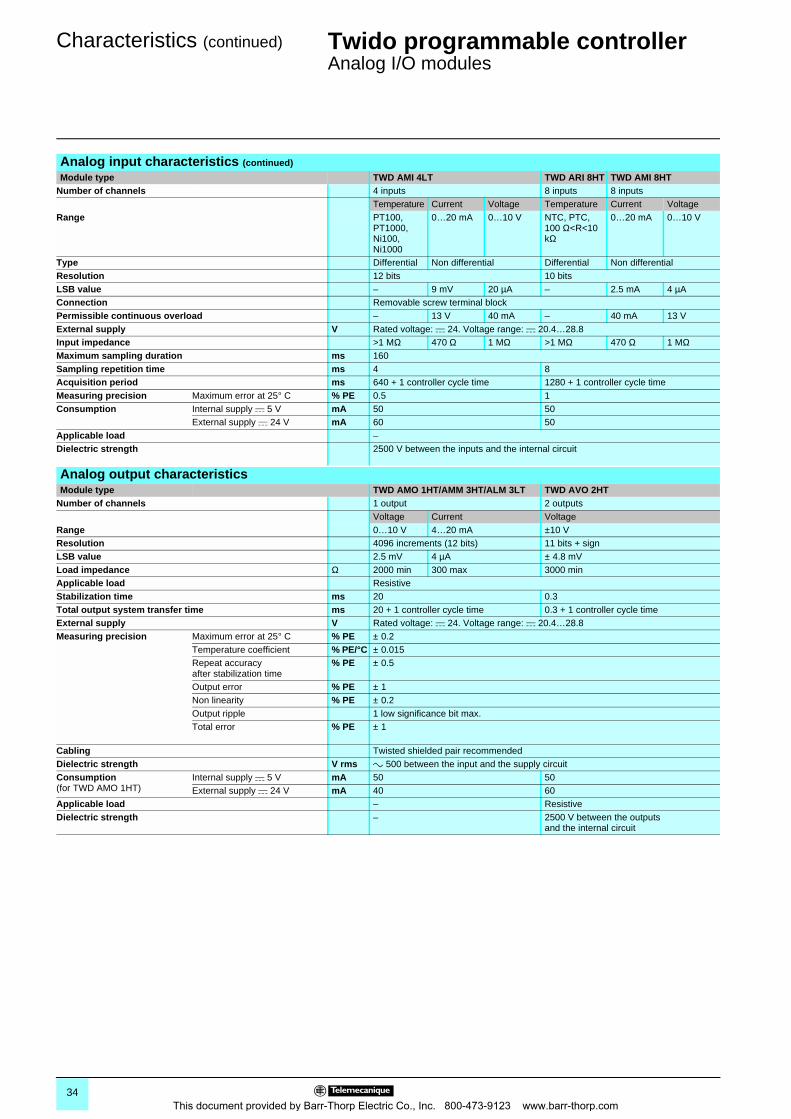
Analog input characteristics (continued)
Module type TWD AMI 4LT TWD ARI 8HT TWD AMI 8HTNumber of channels 4 inputs 8 inputs 8 inputs
Temperature Current Voltage Temperature Current VoltageRange PT100,
PT1000, Ni100, Ni1000
0…20 mA 0…10 V NTC, PTC, 100 Ω<R<10 kΩ
0…20 mA 0…10 V
Type Differential Non differential Differential Non differentialResolution 12 bits 10 bitsLSB value – 9 mV 20 µA – 2.5 mA 4 µAConnection Removable screw terminal blockPermissible continuous overload – 13 V 40 mA – 40 mA 13 VExternal supply V Rated voltage: c 24. Voltage range: c 20.4…28.8Input impedance >1 MΩ 470 Ω 1 MΩ >1 MΩ 470 Ω 1 MΩMaximum sampling duration ms 160Sampling repetition time ms 4 8Acquisition period ms 640 + 1 controller cycle time 1280 + 1 controller cycle timeMeasuring precision Maximum error at 25° C % PE 0.5 1Consumption Internal supply c 5 V mA 50 50
External supply c 24 V mA 60 50Applicable load –Dielectric strength 2500 V between the inputs and the internal circuit
Analog output characteristicsModule type TWD AMO 1HT/AMM 3HT/ALM 3LT TWD AVO 2HT
Number of channels 1 output 2 outputsVoltage Current Voltage
Range 0…10 V 4…20 mA ±10 VResolution 4096 increments (12 bits) 11 bits + signLSB value 2.5 mV 4 µA ± 4.8 mVLoad impedance Ω 2000 min 300 max 3000 minApplicable load ResistiveStabilization time ms 20 0.3Total output system transfer time ms 20 + 1 controller cycle time 0.3 + 1 controller cycle timeExternal supply V Rated voltage: c 24. Voltage range: c 20.4…28.8Measuring precision Maximum error at 25° C % PE ± 0.2
Temperature coefficient % PE/°C ± 0.015Repeat accuracy after stabilization time
% PE ± 0.5
Output error % PE ± 1Non linearity % PE ± 0.2Output ripple 1 low significance bit max.Total error % PE ± 1
Cabling Twisted shielded pair recommendedDielectric strength V rms a 500 between the input and the supply circuitConsumption(for TWD AMO 1HT)
Internal supply c 5 V mA 50 50External supply c 24 V mA 40 60
Applicable load – ResistiveDielectric strength – 2500 V between the outputs
and the internal circuit
34This document provided by Barr-Thorp Electric Co., Inc. 800-473-9123 www.barr-thorp.com
References,dimensions
Twido programmable controller 0
Analog I/O modules
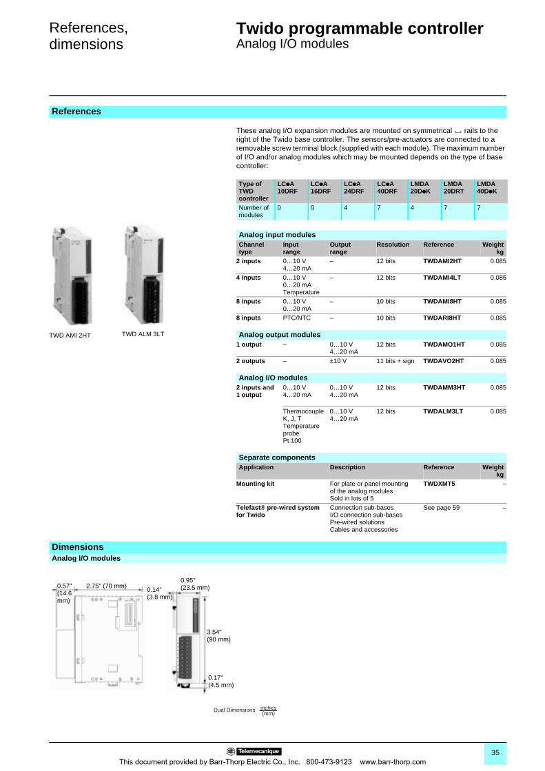
These analog I/O expansion modules are mounted on symmetrical 7 rails to the right of the Twido base controller. The sensors/pre-actuators are connected to a removable screw terminal block (supplied with each module). The maximum number of I/O and/or analog modules which may be mounted depends on the type of base controller:
References
Type of TWD controller
LCpA 10DRF
LCpA 16DRF
LCpA 24DRF
LCpA 40DRF
LMDA 20DpK
LMDA 20DRT
LMDA 40DpK
Number of modules
0 0 4 7 4 7 7
TWD AMI 2HT TWD ALM 3LT
Analog input modulesChannel type
Input range
Output range
Resolution Reference Weightkg
2 inputs 0…10 V4…20 mA
– 12 bits TWDAMI2HT 0.085
4 inputs 0…10 V0…20 mATemperature
– 12 bits TWDAMI4LT 0.085
8 inputs 0…10 V0…20 mA
– 10 bits TWDAMI8HT 0.085
8 inputs PTC/NTC – 10 bits TWDARI8HT 0.085
Analog output modules1 output – 0…10 V
4…20 mA12 bits TWDAMO1HT 0.085
2 outputs – ±10 V 11 bits + sign TWDAVO2HT 0.085
Analog I/O modules2 inputs and 1 output
0…10 V4…20 mA
0…10 V4…20 mA
12 bits TWDAMM3HT 0.085
Thermocouple K, J, TTemperature probePt 100
0…10 V4…20 mA
12 bits TWDALM3LT 0.085
Separate componentsApplication Description Reference Weight
kgMounting kit For plate or panel mounting
of the analog modulesSold in lots of 5
TWDXMT5 –
Telefast® pre-wired system for Twido
Connection sub-basesI/O connection sub-basesPre-wired solutionsCables and accessories
See page 59 –
DimensionsAnalog I/O modules
0.14"(3.8 mm)
0.95"(23.5 mm)
0.17"(4.5 mm)
3.54"(90 mm)
0.57"(14.6 mm)
2.75" (70 mm)
Dual Dimensions inches(mm)
35This document provided by Barr-Thorp Electric Co., Inc. 800-473-9123 www.barr-thorp.com
Connections Twido programmable controller 0
Analog I/O modules
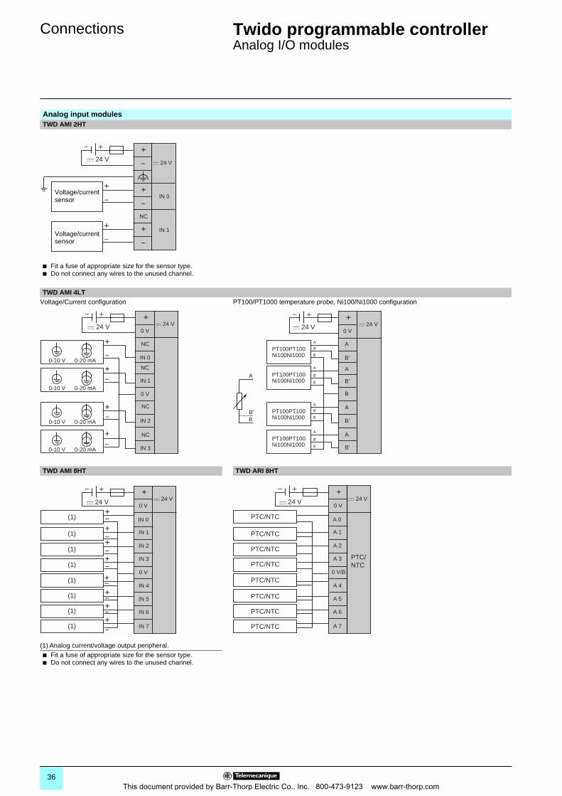
Analog input modulesTWD AMI 2HT
b Fit a fuse of appropriate size for the sensor type.b Do not connect any wires to the unused channel.
TWD AMI 4LTVoltage/Current configuration PT100/PT1000 temperature probe, Ni100/Ni1000 configuration
TWD AMI 8HT TWD ARI 8HT
(1) Analog current/voltage output peripheral.b Fit a fuse of appropriate size for the sensor type.b Do not connect any wires to the unused channel.
+
NC
IN 0
IN 1
–
–
+
–+
–
+
–
+
24 V 24 V
+
–
Voltage/current sensor
Voltage/current sensor
+
NC
NC
NC
NC
0 V
0 V
IN 00-20 mA
IN 1
IN 2
IN 3
–
+
–
+ 24 V 24 V
+–
0-10 V
0-20 mA0-10 V
0-20 mA
+–
+–
0-10 V
0-20 mA0-10 V
+
A
0 V
B'
A
A
B'
B
B'
B
A
A
A
B'
B'
B'
B
PT100PT100Ni100Ni1000
PT100PT100Ni100Ni1000
– +c 24 Vc 24 V
A
A
B'
A
B'B B
B'
B
PT100PT100Ni100Ni1000
PT100PT100Ni100Ni1000
+
0 V
0 V
IN 0
IN 1
IN 5
IN 6
IN 4
IN 2
IN 7
IN 3
–
+–
+
+
24 V 24 V
+–
–+
–+–+–
–+
(1)
(1)
(1)
(1)
(1)
(1)
(1)
(1)
+–
+
0 V
0 V/B
A 0
A 1
A 5
A 6
A 4
A 2
A 7
A 3
– + 24 V 24 V
PTC/NTC
PTC/NTC
PTC/NTC
PTC/NTC
PTC/NTC
PTC/NTC
PTC/NTC
PTC/NTC
PTC/NTC
36This document provided by Barr-Thorp Electric Co., Inc. 800-473-9123 www.barr-thorp.com
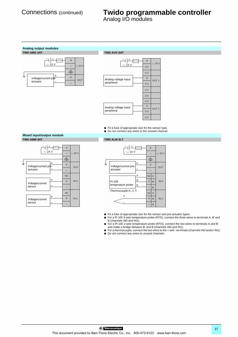
Connections (continued) Twido programmable controller 0
Analog I/O modules
Analog output modulesTWD AMO 1HT TWD AVO 2HT
b Fit a fuse of appropriate size for the sensor type.b Do not connect any wires to the unused channel.
Mixed input/output moduleTWD AMM 3HT TWD ALM 3LT
b Fit a fuse of appropriate size for the sensor and pre-actuator types.b For a Pt 100 3-wire temperature probe (RTD), connect the three wires to terminals A, B' and
B (channels IN0 and IN1).b For a Pt 100 2-wire temperature probe (RTD), connect the two wires to terminals A and B'
and make a bridge between B' and B (channels IN0 and IN1). b For a thermocouple, connect the two wires to the + and - terminals (channels IN0 and/or IN1).b Do not connect any wires to unused channels.
+
OUT
–
–
+
–+
–
+
24 V 24 V
Voltage/current pre-actuator
+
+
+
OUT 1
OUT 2
– + 24 V
24 V0 V
0 V
0 V
0 V
0 V
0 V
0 V
0 V
Analog voltage input peripheral
Analog voltage input peripheral
+
NC
IN 0
OUT
IN 1
–
–
+
–+
–
+
–
NC
+
–
+
24 V 24 V
+
–
+
–
Voltage/current pre-actuator
Voltage/current sensor
Voltage/current sensor
+
NC A
B'
B
A
B'
B
A
B'
B
IN 0
OUT
IN 1
–
–
+
+
–
–
+
–
+
–
NC
+
–
+
24 V 24 V
Voltage/current pre-actuator
Pt 100 temperature probe
Thermocouple K, J, T
37This document provided by Barr-Thorp Electric Co., Inc. 800-473-9123 www.barr-thorp.com
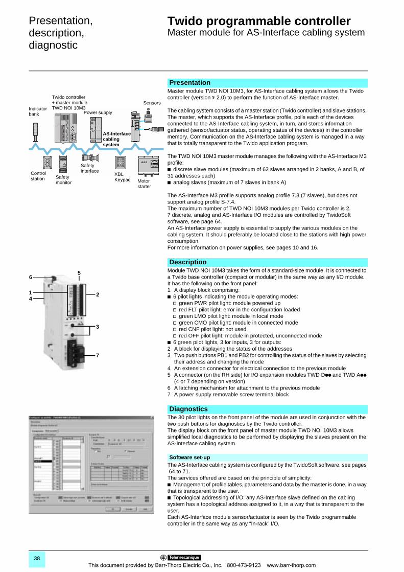
Presentation,description,diagnostic 0
Twido programmable controller 0
Master module for AS-Interface cabling system
PresentationMaster module TWD NOI 10M3, for AS-Interface cabling system allows the Twido controller (version u 2.0) to perform the function of AS-Interface master.
The cabling system consists of a master station (Twido controller) and slave stations. The master, which supports the AS-Interface profile, polls each of the devices connected to the AS-Interface cabling system, in turn, and stores information gathered (sensor/actuator status, operating status of the devices) in the controller memory. Communication on the AS-Interface cabling system is managed in a way that is totally transparent to the Twido application program.
The TWD NOI 10M3 master module manages the following with the AS-Interface M3 profile:b discrete slave modules (maximum of 62 slaves arranged in 2 banks, A and B, of 31 addresses each)b analog slaves (maximum of 7 slaves in bank A)
The AS-Interface M3 profile supports analog profile 7.3 (7 slaves), but does not support analog profile S-7.4.The maximum number of TWD NOI 10M3 modules per Twido controller is 2.7 discrete, analog and AS-Interface I/O modules are controlled by TwidoSoft software, see page 64.An AS-Interface power supply is essential to supply the various modules on the cabling system. It should preferably be located close to the stations with high power consumption. For more information on power supplies, see pages 10 and 16.
DescriptionModule TWD NOI 10M3 takes the form of a standard-size module. It is connected to a Twido base controller (compact or modular) in the same way as any I/O module.It has the following on the front panel:1 A display block comprising:b 6 pilot lights indicating the module operating modes:
v green PWR pilot light: module powered upv red FLT pilot light: error in the configuration loadedv green LMO pilot light: module in local modev green CMO pilot light: module in connected modev red CNF pilot light: not usedv red OFF pilot light: module in protected, unconnected mode
b 6 green pilot lights, 3 for inputs, 3 for outputs:2 A block for displaying the status of the addresses3 Two push buttons PB1 and PB2 for controlling the status of the slaves by selecting
their address and changing the mode4 An extension connector for electrical connection to the previous module5 A connector (on the RH side) for I/O expansion modules TWD Dpp and TWD App
(4 or 7 depending on version)6 A latching mechanism for attachment to the previous module7 A power supply removable screw terminal block
DiagnosticsThe 30 pilot lights on the front panel of the module are used in conjunction with the two push buttons for diagnostics by the Twido controller.The display block on the front panel of master module TWD NOI 10M3 allows simplified local diagnostics to be performed by displaying the slaves present on the AS-Interface cabling system.
Software set-upThe AS-Interface cabling system is configured by the TwidoSoft software, see pages 64 to 71.
The services offered are based on the principle of simplicity: b Management of profile tables, parameters and data by the master is done, in a way that is transparent to the user.b Topological addressing of I/O: any AS-Interface slave defined on the cabling system has a topological address assigned to it, in a way that is transparent to the user.Each AS-Interface module sensor/actuator is seen by the Twido programmable controller in the same way as any “In-rack” I/O.
Sensors
Power supply
Control station
Twido controller + master module TWD NOI 10M3
AS-Interface cabling system
Indicator bank
Safety monitor Motor
starter
Safety interface
XBLKeypad
14
2
65
3
7
38This document provided by Barr-Thorp Electric Co., Inc. 800-473-9123 www.barr-thorp.com
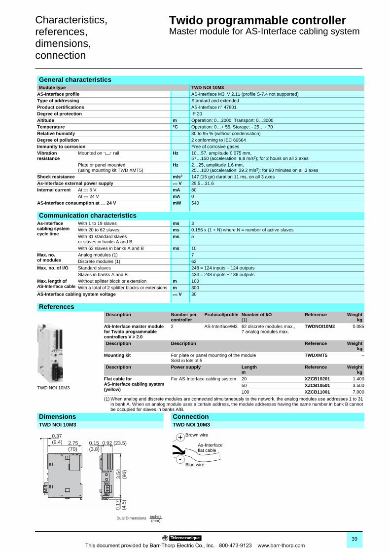
Characteristics,references,dimensions,connection 0
Twido programmable controller 0
Master module for AS-Interface cabling system
General characteristicsModule type TWD NOI 10M3
AS-Interface profile AS-Interface M3, V 2.11 (profile S-7.4 not supported)Type of addressing Standard and extendedProduct certifications AS-Interface n° 47801Degree of protection IP 20Altitude m Operation: 0…2000. Transport: 0…3000Temperature °C Operation: 0…+ 55. Storage: - 25…+ 70Relative humidity 30 to 95 % (without condensation)Degree of pollution 2 conforming to IEC 60664Immunity to corrosion Free of corrosive gasesVibration resistance
Mounted on 5 rail Hz 10…57, amplitude 0.075 mm,57…150 (acceleration: 9.8 m/s2); for 2 hours on all 3 axes
Plate or panel mounted (using mounting kit TWD XMT5)
Hz 2…25, amplitude 1.6 mm,25…100 (acceleration: 39.2 m/s2); for 90 minutes on all 3 axes
Shock resistance m/s2 147 (15 gn) duration 11 ms, on all 3 axesAs-Interface external power supply c V 29.5…31.6 Internal current At c 5 V mA 80
At c 24 V mA 0AS-Interface consumption at c 24 V mW 540
Communication characteristicsAs-Interface cabling system cycle time
With 1 to 19 slaves ms 3With 20 to 62 slaves ms 0.156 x (1 + N) where N = number of active slavesWith 31 standard slaves or slaves in banks A and B
ms 5
With 62 slaves in banks A and B ms 10Max. no. of modules
Analog modules (1) 7Discrete modules (1) 62
Max. no. of I/O Standard slaves 248 = 124 inputs + 124 outputsSlaves in banks A and B 434 = 248 inputs + 186 outputs
Max. length of AS-Interface cable
Without splitter block or extension m 100With a total of 2 splitter blocks or extensions m 300
AS-Interface cabling system voltage c V 30
ReferencesDescription Number per
controllerProtocol/profile Number of I/O
(1)Reference Weight
kgAS-Interface master module for Twido programmable controllers V u 2.0
2 AS-Interface/M3 62 discrete modules max.,7 analog modules max.
TWDNOI10M3 0.085
Description Description Reference Weightkg
Mounting kit For plate or panel mounting of the moduleSold in lots of 5
TWDXMT5 –
Description Power supply Lengthm
Reference Weightkg
Flat cable for AS-Interface cabling system (yellow)
For AS-Interface cabling system 20 XZCB10201 1.40050 XZCB10501 3.500100 XZCB11001 7.000
(1) When analog and discrete modules are connected simultaneously to the network, the analog modules use addresses 1 to 31 in bank A. When an analog module uses a certain address, the module addresses having the same number in bank B cannot be occupied for slaves in banks A/B.
Dimensions ConnectionTWD NOI 10M3 TWD NOI 10M3
TWD NOI 10M3
0.17
(4.5
)
2.75(70)
3.54
(90)
0.37(9.4) 0.15
(3.8)0.92 (23.5)
Dual Dimensions inches(mm)
Brown wire
Blue wire
As-Interface flat cable
39This document provided by Barr-Thorp Electric Co., Inc. 800-473-9123 www.barr-thorp.com
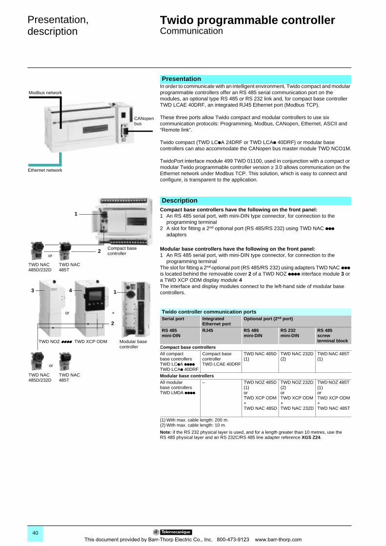
Presentation,description 0
Twido programmable controller 0
Communication
In order to communicate with an intelligent environment, Twido compact and modular programmable controllers offer an RS 485 serial communication port on the modules, an optional type RS 485 or RS 232 link and, for compact base controller TWD LCAE 40DRF, an integrated RJ45 Ethernet port (Modbus TCP).
These three ports allow Twido compact and modular controllers to use six communication protocols: Programming, Modbus, CANopen, Ethernet, ASCII and “Remote link”.
Twido compact (TWD LCpA 24DRF or TWD LCAp 40DRF) or modular base controllers can also accommodate the CANopen bus master module TWD NCO1M.
TwidoPort interface module 499 TWD 01100, used in conjunction with a compact or modular Twido programmable controller version ≥ 3.0 allows communication on the Ethernet network under Modbus TCP. This solution, which is easy to connect and configure, is transparent to the application.
Compact base controllers have the following on the front panel: 1 An RS 485 serial port, with mini-DIN type connector, for connection to the
programming terminal2 A slot for fitting a 2nd optional port (RS 485/RS 232) using TWD NAC ppp
adapters
Modular base controllers have the following on the front panel: 1 An RS 485 serial port, with mini-DIN type connector, for connection to the
programming terminalThe slot for fitting a 2nd optional port (RS 485/RS 232) using adapters TWD NAC ppp is located behind the removable cover 2 of a TWD NOZ pppp interface module 3 or a TWD XCP ODM display module 4The interface and display modules connect to the left-hand side of modular base controllers.
Presentation
Modbus network
Ethernet network
CANopenbus
Description
1
2
TWD NAC 485D/232D
TWD NAC 485T
Compact base controlleror
Modular base controller
TWD NAC 485D/232D
TWD NAC 485T
TWD NOZ pppp
1
or
3 4
2
or +
TWD XCP ODM
Twido controller communication portsSerial port Integrated
Ethernet portOptional port (2nd port)
RS 485mini-DIN
RJ45 RS 485mini-DIN
RS 232mini-DIN
RS 485screw terminal block
Compact base controllersAll compact base controllers TWD LCpA ppppTWD LCAp 40DRF
Compact base controller TWD LCAE 40DRF
TWD NAC 485D (1)
TWD NAC 232D (2)
TWD NAC 485T (1)
Modular base controllersAll modular base controllers TWD LMDA pppp
– TWD NOZ 485D (1) orTWD XCP ODM + TWD NAC 485D
TWD NOZ 232D (2) orTWD XCP ODM + TWD NAC 232D
TWD NOZ 485T (1) orTWD XCP ODM + TWD NAC 485T
(1) With max. cable length: 200 m.(2) With max. cable length: 10 m.
Note: if the RS 232 physical layer is used, and for a length greater than 10 metres, use the RS 485 physical layer and an RS 232C/RS 485 line adapter reference XGS Z24.
40This document provided by Barr-Thorp Electric Co., Inc. 800-473-9123 www.barr-thorp.com
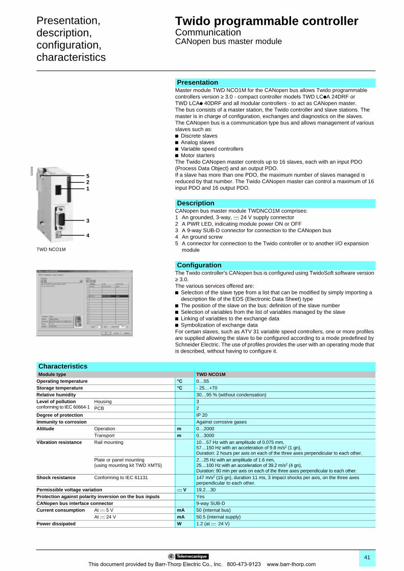
Presentation,description,configuration,characteristics 0
Twido programmable controller 0
CommunicationCANopen bus master module
Master module TWD NCO1M for the CANopen bus allows Twido programmable controllers version ≥ 3.0 - compact controller models TWD LCpA 24DRF or TWD LCAp 40DRF and all modular controllers - to act as CANopen master.The bus consists of a master station, the Twido controller and slave stations. The master is in charge of configuration, exchanges and diagnostics on the slaves.The CANopen bus is a communication type bus and allows management of various slaves such as:b Discrete slavesb Analog slavesb Variable speed controllersb Motor startersThe Twido CANopen master controls up to 16 slaves, each with an input PDO (Process Data Object) and an output PDO.If a slave has more than one PDO, the maximum number of slaves managed is reduced by that number. The Twido CANopen master can control a maximum of 16 input PDO and 16 output PDO.
CANopen bus master module TWDNCO1M comprises: 1 An grounded, 3-way, c 24 V supply connector2 A PWR LED, indicating module power ON or OFF3 A 9-way SUB-D connector for connection to the CANopen bus4 An ground screw5 A connector for connection to the Twido controller or to another I/O expansion
module
The Twido controller's CANopen bus is configured using TwidoSoft software version ≥ 3.0. The various services offered are:b Selection of the slave type from a list that can be modified by simply importing a
description file of the EDS (Electronic Data Sheet) typeb The position of the slave on the bus: definition of the slave numberb Selection of variables from the list of variables managed by the slaveb Linking of variables to the exchange datab Symbolization of exchange dataFor certain slaves, such as ATV 31 variable speed controllers, one or more profiles are supplied allowing the slave to be configured according to a mode predefined by Schneider Electric. The use of profiles provides the user with an operating mode that is described, without having to configure it.
Presentation
Description
TWD NCO1M
12
3
4
55326
59
Configuration
CharacteristicsModule type TWD NCO1M
Operating temperature °C 0…55Storage temperature °C - 25…+70Relative humidity 30…95 % (without condensation)Level of pollutionconforming to IEC 60664-1
Housing 3PCB 2
Degree of protection IP 20Immunity to corrosion Against corrosive gasesAltitude Operation m 0…2000
Transport m 0…3000Vibration resistance Rail mounting 10…57 Hz with an amplitude of 0.075 mm,
57…150 Hz with an acceleration of 9.8 m/s2 (1 gn),Duration: 2 hours per axis on each of the three axes perpendicular to each other.
Plate or panel mounting(using mounting kit TWD XMT5)
2…25 Hz with an amplitude of 1.6 mm,25…100 Hz with an acceleration of 39.2 m/s2 (4 gn),Duration: 90 min per axis on each of the three axes perpendicular to each other.
Shock resistance Conforming to IEC 61131 147 m/s2 (15 gn), duration 11 ms, 3 impact shocks per axis, on the three axes perpendicular to each other.
Permissible voltage variation c V 19.2…30Protection against polarity inversion on the bus inputs YesCANopen bus interface connector 9-way SUB-DCurrent consumption At c 5 V mA 50 (internal bus)
At c 24 V mA 50.5 (internal supply)Power dissipated W 1.2 (at c 24 V)
41This document provided by Barr-Thorp Electric Co., Inc. 800-473-9123 www.barr-thorp.com
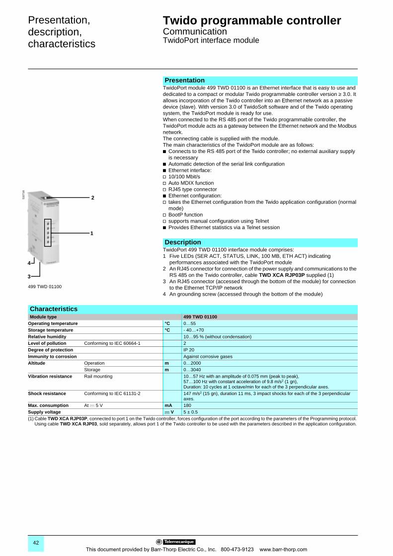
Presentation,description,characteristics 0
Twido programmable controller 0
CommunicationTwidoPort interface module
TwidoPort module 499 TWD 01100 is an Ethernet interface that is easy to use and dedicated to a compact or modular Twido programmable controller version ≥ 3.0. It allows incorporation of the Twido controller into an Ethernet network as a passive device (slave). With version 3.0 of TwidoSoft software and of the Twido operating system, the TwidoPort module is ready for use.When connected to the RS 485 port of the Twido programmable controller, the TwidoPort module acts as a gateway between the Ethernet network and the Modbus network.The connecting cable is supplied with the module.The main characteristics of the TwidoPort module are as follows:b Connects to the RS 485 port of the Twido controller; no external auxiliary supply
is necessaryb Automatic detection of the serial link configurationb Ethernet interface:v 10/100 Mbit/sv Auto MDIX functionv RJ45 type connectorb Ethernet configuration:v takes the Ethernet configuration from the Twido application configuration (normal
mode)v BootP functionv supports manual configuration using Telnetb Provides Ethernet statistics via a Telnet session
TwidoPort 499 TWD 01100 interface module comprises: 1 Five LEDs (SER ACT, STATUS, LINK, 100 MB, ETH ACT) indicating
performances associated with the TwidoPort module2 An RJ45 connector for connection of the power supply and communications to the
RS 485 on the Twido controller, cable TWD XCA RJP03P supplied (1)3 An RJ45 connector (accessed through the bottom of the module) for connection
to the Ethernet TCP/IP network4 An grounding screw (accessed through the bottom of the module)
Presentation
Description
499 TWD 01100
2
1
3
4
5327
18
CharacteristicsModule type 499 TWD 01100
Operating temperature °C 0…55Storage temperature °C - 40…+70Relative humidity 10…95 % (without condensation)Level of pollution Conforming to IEC 60664-1 2Degree of protection IP 20Immunity to corrosion Against corrosive gasesAltitude Operation m 0…2000
Storage m 0…3040Vibration resistance Rail mounting 10…57 Hz with an amplitude of 0.075 mm (peak to peak),
57…100 Hz with constant acceleration of 9.8 m/s2 (1 gn),Duration: 10 cycles at 1 octave/min for each of the 3 perpendicular axes.
Shock resistance Conforming to IEC 61131-2 147 m/s2 (15 gn), duration 11 ms, 3 impact shocks for each of the 3 perpendicular axes.
Max. consumption At c 5 V mA 180Supply voltage c V 5 ± 0.5(1) Cable TWD XCA RJP03P, connected to port 1 on the Twido controller, forces configuration of the port according to the parameters of the Programming protocol.
Using cable TWD XCA RJP03, sold separately, allows port 1 of the Twido controller to be used with the parameters described in the application configuration.
42This document provided by Barr-Thorp Electric Co., Inc. 800-473-9123 www.barr-thorp.com
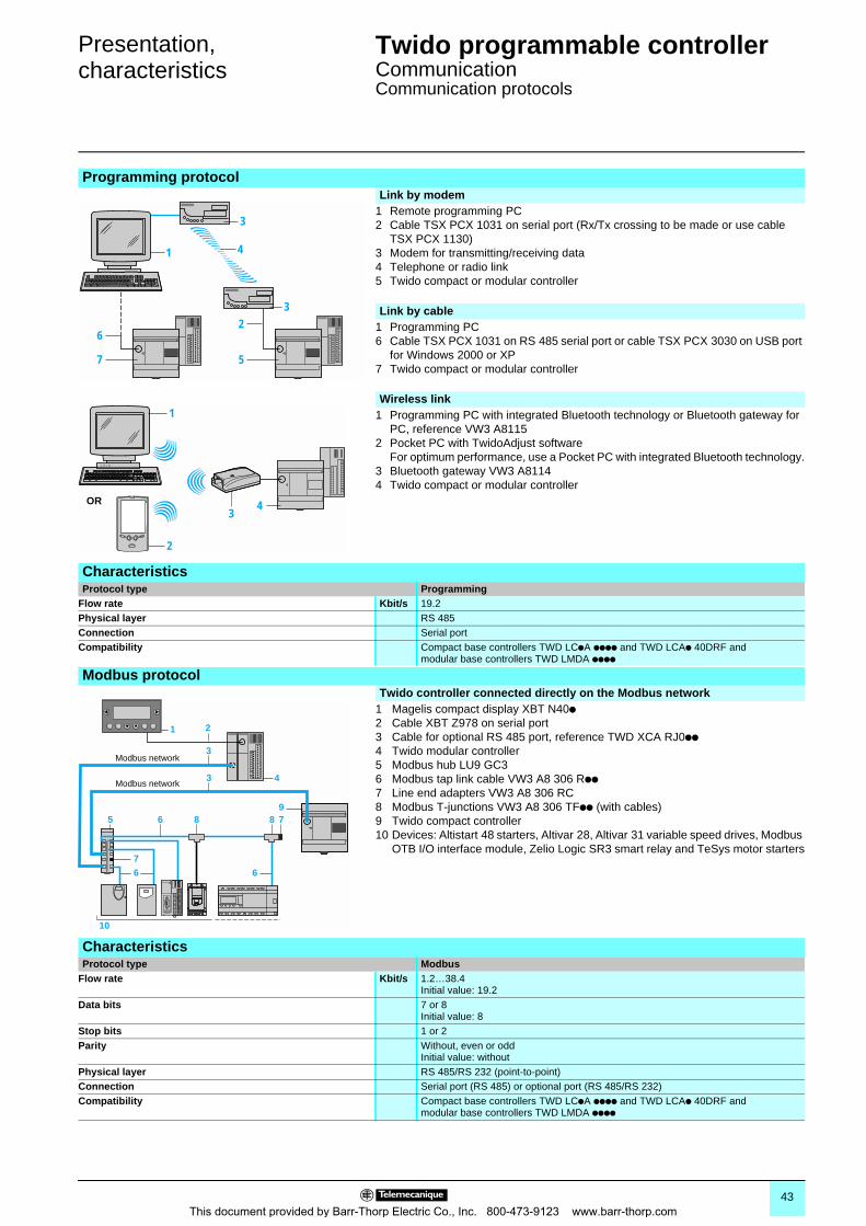
Presentation,characteristics 0
Twido programmable controller 0
CommunicationCommunication protocols
Programming protocol Link by modem
1 Remote programming PC2 Cable TSX PCX 1031 on serial port (Rx/Tx crossing to be made or use cable
TSX PCX 1130)3 Modem for transmitting/receiving data4 Telephone or radio link5 Twido compact or modular controller
Link by cable1 Programming PC6 Cable TSX PCX 1031 on RS 485 serial port or cable TSX PCX 3030 on USB port
for Windows 2000 or XP7 Twido compact or modular controller
Wireless link1 Programming PC with integrated Bluetooth technology or Bluetooth gateway for
PC, reference VW3 A81152 Pocket PC with TwidoAdjust software
For optimum performance, use a Pocket PC with integrated Bluetooth technology.3 Bluetooth gateway VW3 A81144 Twido compact or modular controller
CharacteristicsProtocol type Programming
Flow rate Kbit/s 19.2Physical layer RS 485Connection Serial portCompatibility Compact base controllers TWD LCpA pppp and TWD LCAp 40DRF and
modular base controllers TWD LMDA pppp
Modbus protocol Twido controller connected directly on the Modbus network
1 Magelis compact display XBT N40p2 Cable XBT Z978 on serial port3 Cable for optional RS 485 port, reference TWD XCA RJ0pp4 Twido modular controller5 Modbus hub LU9 GC36 Modbus tap link cable VW3 A8 306 Rpp7 Line end adapters VW3 A8 306 RC8 Modbus T-junctions VW3 A8 306 TFpp (with cables)9 Twido compact controller10 Devices: Altistart 48 starters, Altivar 28, Altivar 31 variable speed drives, Modbus
OTB I/O interface module, Zelio Logic SR3 smart relay and TeSys motor starters
CharacteristicsProtocol type Modbus
Flow rate Kbit/s 1.2…38.4Initial value: 19.2
Data bits 7 or 8Initial value: 8
Stop bits 1 or 2Parity Without, even or odd
Initial value: withoutPhysical layer RS 485/RS 232 (point-to-point)Connection Serial port (RS 485) or optional port (RS 485/RS 232)Compatibility Compact base controllers TWD LCpA pppp and TWD LCAp 40DRF and
modular base controllers TWD LMDA pppp
1
3
4
3
5
2
7
6
1
2
34OR
7
6 6
65 8 8 79
3
1
10
2
43Modbus network
Modbus network
43This document provided by Barr-Thorp Electric Co., Inc. 800-473-9123 www.barr-thorp.com
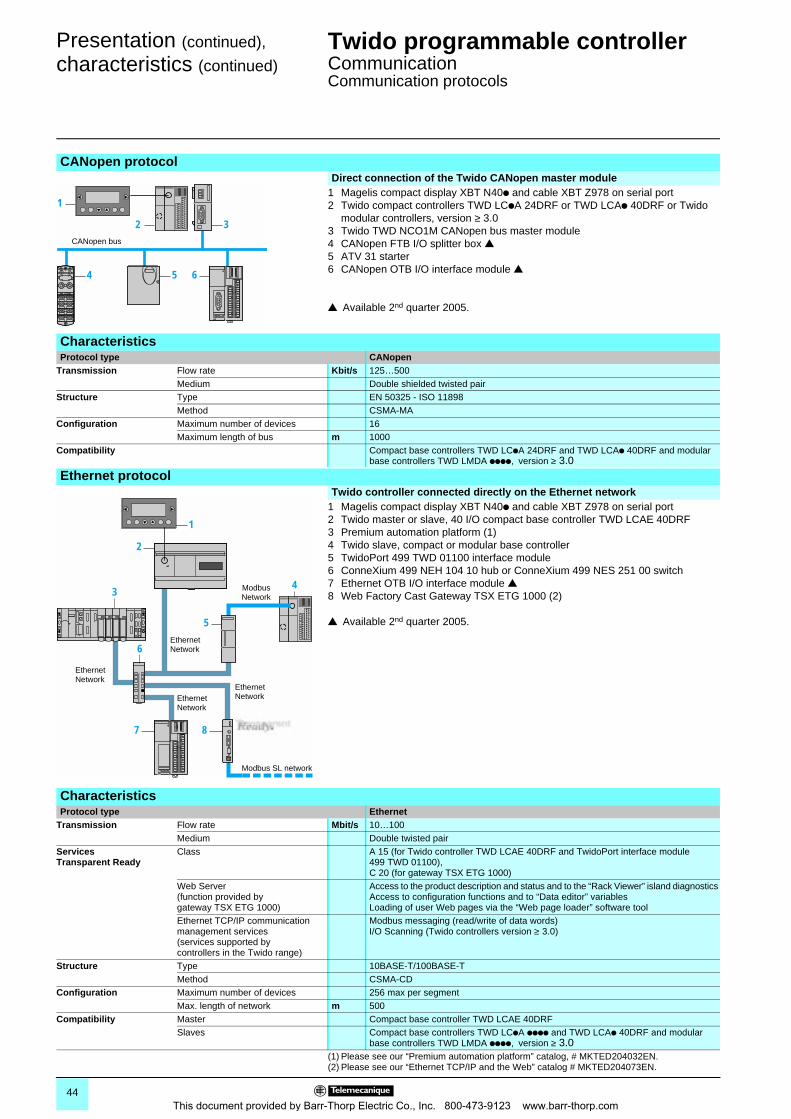
Presentation (continued),
characteristics (continued) 0
Twido programmable controller 0
CommunicationCommunication protocols
CANopen protocol Direct connection of the Twido CANopen master module
1 Magelis compact display XBT N40p and cable XBT Z978 on serial port2 Twido compact controllers TWD LCpA 24DRF or TWD LCAp 40DRF or Twido
modular controllers, version ≥ 3.03 Twido TWD NCO1M CANopen bus master module4 CANopen FTB I/O splitter box r5 ATV 31 starter6 CANopen OTB I/O interface module r
r Available 2nd quarter 2005.
CharacteristicsProtocol type CANopen
Transmission Flow rate Kbit/s 125…500Medium Double shielded twisted pair
Structure Type EN 50325 - ISO 11898Method CSMA-MA
Configuration Maximum number of devices 16Maximum length of bus m 1000
Compatibility Compact base controllers TWD LCpA 24DRF and TWD LCAp 40DRF and modular base controllers TWD LMDA pppp, version ≥ 3.0
Ethernet protocol Twido controller connected directly on the Ethernet network
1 Magelis compact display XBT N40p and cable XBT Z978 on serial port2 Twido master or slave, 40 I/O compact base controller TWD LCAE 40DRF3 Premium automation platform (1)4 Twido slave, compact or modular base controller5 TwidoPort 499 TWD 01100 interface module6 ConneXium 499 NEH 104 10 hub or ConneXium 499 NES 251 00 switch7 Ethernet OTB I/O interface module r8 Web Factory Cast Gateway TSX ETG 1000 (2)
r Available 2nd quarter 2005.
CharacteristicsProtocol type Ethernet
Transmission Flow rate Mbit/s 10…100Medium Double twisted pair
Services Transparent Ready
Class A 15 (for Twido controller TWD LCAE 40DRF and TwidoPort interface module 499 TWD 01100),C 20 (for gateway TSX ETG 1000)
Web Server (function provided by gateway TSX ETG 1000)
Access to the product description and status and to the “Rack Viewer” island diagnosticsAccess to configuration functions and to “Data editor” variablesLoading of user Web pages via the “Web page loader” software tool
Ethernet TCP/IP communication management services(services supported by controllers in the Twido range)
Modbus messaging (read/write of data words)I/O Scanning (Twido controllers version ≥ 3.0)
Structure Type 10BASE-T/100BASE-TMethod CSMA-CD
Configuration Maximum number of devices 256 max per segmentMax. length of network m 500
Compatibility Master Compact base controller TWD LCAE 40DRFSlaves Compact base controllers TWD LCpA pppp and TWD LCAp 40DRF and modular
base controllers TWD LMDA pppp, version ≥ 3.0(1) Please see our “Premium automation platform” catalog, # MKTED204032EN.(2) Please see our “Ethernet TCP/IP and the Web” catalog # MKTED204073EN.
3
5 64
2
1
CANopen bus
4
6
2
5
1
7 8
3
EthernetNetwork
EthernetNetwork
ModbusNetwork
EthernetNetwork
EthernetNetwork
Modbus SL network
44This document provided by Barr-Thorp Electric Co., Inc. 800-473-9123 www.barr-thorp.com
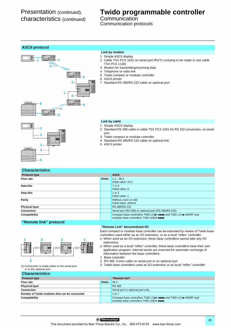
Presentation (continued), characteristics (continued) 0
Twido programmable controller 0
CommunicationCommunication protocols
ASCII protocol Link by modem
1 Simple ASCII display2 Cable TSX PCX 1031 on serial port (Rx/Tx crossing to be made or use cable
TSX PCX 1130)3 Modem for transmitting/receiving data4 Telephone or radio link5 Twido compact or modular controller6 ASCII printer7 Standard RS 485/RS 232 cable on optional port
Link by cable1 Simple ASCII display2 Standard RS 485 cable or cable TSX PCX 1031 for RS 232 conversion, on serial
port3 Twido compact or modular controller4 Standard RS 485/RS 232 cable on optional link5 ASCII printer
CharacteristicsProtocol type ASCII
Flow rate Kbit/s 1.2…38.4Initial value: 19.2
Data bits 7 or 8Initial value: 8
Stop bits 1 or 2Initial value: 1
Parity Without, even or oddInitial value: without
Physical layer RS 485/RS 232Connection Serial port (RS 485) or optional port (RS 485/RS 232)Compatibility Compact base controllers TWD LCpA pppp and TWD LCAp 40DRF and
modular base controllers TWD LMDA pppp
“Remote link” protocol
(1) Connection is made either to the serial port, or to the optional port.
“Remote Link” decentralized I/OEach compact or modular base controller can be extended by means of Twido base controllers used either as an I/O extension, or as a local “reflex” controller. v When used as an I/O extension, these base controllers cannot take any I/O
extensions.v When used as a local “reflex” controller, these base controllers have their own
application program. Internal words are reserved for automatic exchange of information between the base controllers.
1 Base controller2 RS 485, 3-wire cable on serial port or on optional port3 Twido base controllers used as I/O extension or as local “reflex” controller
CharacteristicsProtocol type “Remote link”
Flow rate Kbit/s 38.4Physical layer RS 485Connection Serial port or optional port only.Number of Twido modules that can be connected 1 to 7Compatibility Compact base controllers TWD LCpA pppp and TWD LCAp 40DRF and
modular base controllers TWD LMDA pppp
1
6
3
3
4
4
3
3
5
2
7
1
5
3
2
4
1 3 3
2
(1)(1)
3
(1)
45This document provided by Barr-Thorp Electric Co., Inc. 800-473-9123 www.barr-thorp.com
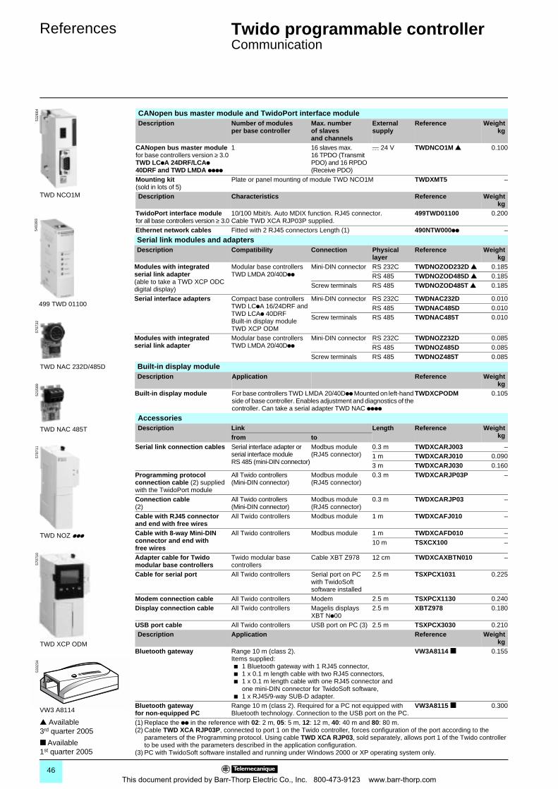
References 0 Twido programmable controller 0
Communication
CANopen bus master module and TwidoPort interface module Description Number of modules
per base controllerMax. number of slaves and channels
Externalsupply
Reference Weightkg
CANopen bus master modulefor base controllers version ≥ 3.0 TWD LCpA 24DRF/LCAp 40DRF and TWD LMDA pppp
1 16 slaves max.16 TPDO (Transmit PDO) and 16 RPDO (Receive PDO)
c 24 V TWDNCO1M r 0.100
Mounting kit (sold in lots of 5)
Plate or panel mounting of module TWD NCO1M TWDXMT5 –
Description Characteristics Reference Weightkg
TwidoPort interface modulefor all base controllers version ≥ 3.0
10/100 Mbit/s. Auto MDIX function. RJ45 connector.Cable TWD XCA RJP03P supplied.
499TWD01100 0.200
Ethernet network cables Fitted with 2 RJ45 connectors Length (1) 490NTW000pp –
Serial link modules and adaptersDescription Compatibility Connection Physical
layerReference Weight
kgModules with integrated serial link adapter(able to take a TWD XCP ODC digital display)
Modular base controllers TWD LMDA 20/40Dpp
Mini-DIN connector RS 232C TWDNOZOD232D r 0.185RS 485 TWDNOZOD485D r 0.185
Screw terminals RS 485 TWDNOZOD485T r 0.185
Serial interface adapters Compact base controllers TWD LCpA 16/24DRF andTWD LCAp 40DRFBuilt-in display module TWD XCP ODM
Mini-DIN connector RS 232C TWDNAC232D 0.010RS 485 TWDNAC485D 0.010
Screw terminals RS 485 TWDNAC485T 0.010
Modules with integrated serial link adapter
Modular base controllers TWD LMDA 20/40Dpp
Mini-DIN connector RS 232C TWDNOZ232D 0.085RS 485 TWDNOZ485D 0.085
Screw terminals RS 485 TWDNOZ485T 0.085
Built-in display moduleDescription Application Reference Weight
kgBuilt-in display module For base controllers TWD LMDA 20/40Dpp Mounted on left-hand
side of base controller. Enables adjustment and diagnostics of the controller. Can take a serial adapter TWD NAC pppp
TWDXCPODM 0.105
AccessoriesDescription Link Length Reference Weight
kgfrom toSerial link connection cables Serial interface adapter or
serial interface module RS 485 (mini-DIN connector)
Modbus module (RJ45 connector)
0.3 m TWDXCARJ003 –1 m TWDXCARJ010 0.0903 m TWDXCARJ030 0.160
Programming protocol connection cable (2) supplied with the TwidoPort module
All Twido controllers(Mini-DIN connector)
Modbus module(RJ45 connector)
0.3 m TWDXCARJP03P –
Connection cable(2)
All Twido controllers(Mini-DIN connector)
Modbus module(RJ45 connector)
0.3 m TWDXCARJP03 –
Cable with RJ45 connector and end with free wires
All Twido controllers Modbus module 1 m TWDXCAFJ010 –
Cable with 8-way Mini-DIN connector and end with free wires
All Twido controllers Modbus module 1 m TWDXCAFD010 –10 m TSXCX100 –
Adapter cable for Twido modular base controllers
Twido modular base controllers
Cable XBT Z978 12 cm TWDXCAXBTN010 –
Cable for serial port All Twido controllers Serial port on PC with TwidoSoft software installed
2.5 m TSXPCX1031 0.225
Modem connection cable All Twido controllers Modem 2.5 m TSXPCX1130 0.240Display connection cable All Twido controllers Magelis displays
XBT Np002.5 m XBTZ978 0.180
USB port cable All Twido controllers USB port on PC (3) 2.5 m TSXPCX3030 0.210Description Application Reference Weight
kgBluetooth gateway Range 10 m (class 2).
Items supplied:b 1 Bluetooth gateway with 1 RJ45 connector,b 1 x 0.1 m length cable with two RJ45 connectors,b 1 x 0.1 m length cable with one RJ45 connector and
one mini-DIN connector for TwidoSoft software,b 1 x RJ45/9-way SUB-D adapter.
VW3A8114 0.155
Bluetooth gateway for non-equipped PC
Range 10 m (class 2). Required for a PC not equipped with Bluetooth technology. Connection to the USB port on the PC.
VW3A8115 0.300
(1) Replace the pp in the reference with 02: 2 m, 05: 5 m, 12: 12 m, 40: 40 m and 80: 80 m.(2) Cable TWD XCA RJP03P, connected to port 1 on the Twido controller, forces configuration of the port according to the
parameters of the Programming protocol. Using cable TWD XCA RJP03, sold separately, allows port 1 of the Twido controller to be used with the parameters described in the application configuration.
(3) PC with TwidoSoft software installed and running under Windows 2000 or XP operating system only.
TWD NOZ ppp
TWD NAC 232D/485D
TWD XCP ODM
TWD NAC 485T
VW3 A8114
TWD NCO1M
5326
6457
0732
5215
8957
0711
5707
1053
3234
499 TWD 01100
5403
93
r Available 3rd quarter 2005
Available 1st quarter 2005
46This document provided by Barr-Thorp Electric Co., Inc. 800-473-9123 www.barr-thorp.com
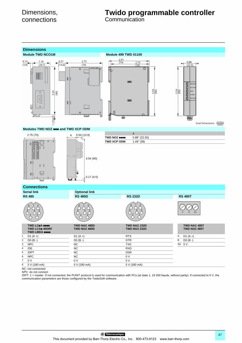
Dimensions,connections 0
Twido programmable controller 0
Communication
DimensionsModule TWD NCO1M Module 499 TWD 01100
Modules TWD NOZ ppp and TWD XCP ODM a
TWD NOZ pppp 0.88” (22.50)TWD XCP ODM 1.49” (38)
ConnectionsSerial link Optional linkRS 485 RS 485D RS 232D RS 485T
TWD LCpA ppppTWD LCAp 40DRFTWD LMDA pppp
TWD NAC 485DTWD NOZ 485D
TWD NAC 232DTWD NOZ 232D
TWD NAC 485TTWD NOZ 485T
1 D1 (A +) D1 (A +) RTS A D1 (A +)2 D0 (B -) D0 (B -) DTR B D0 (B -)3 NPC NC TXD SG 0 V4 /DE NC RXD5 /DPT NC DSR6 NPC NC 0 V7 0 V 0 V 0 V8 5 V (180 mA) 5 V (180 mA) 5 V (180 mA)NC: not connectedNPC: do not connect/DPT: 1 = master. If not connected, the PUNIT protocol is used for communication with PCs (at state 1, 19 200 bauds, without parity). If connected to 0 V, the communication parameters are those configured by the TwidoSoft software.
0.14(3.8)
1.16(29.7)
3.54
(90)
1.17
(4.5
)
0.57(14.6)
2.75(70)
2.91(74) 2.75
(70)
3.54
(90)
3.54
(90)
0.88(22.5)
Dual Dimensions inches(mm)
2.75 (70) a
0.17 (4.5)
3.54 (90)
0.54 (13.9)
12
45 3
8 7 6
12
45 3
8 7 6
12
45 3
8 7 6
A B SG
47This document provided by Barr-Thorp Electric Co., Inc. 800-473-9123 www.barr-thorp.com
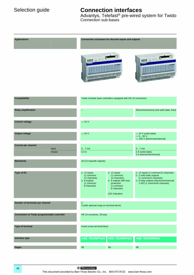
Selection guide Connection interfaces 0
Advantys, Telefast® pre-wired system for TwidoConnection sub-bases
Applications Connection sub-bases for discrete inputs and outputs
Compatibility Twido modular base controllers equipped with HE 10 connectors
Relay amplification – Electromechanical and solid state, fixed
Control voltage c 24 V
Output voltage c 24 V c 24 V (solid state)c 5…30 V,a 250 V (electromechanical)
Current per channelInput 5…7 mA 5…7 mAOutput 0.3 A 2 A (solid state)
3 A (electromechanical)
Modularity 20 (12 inputs/8 outputs)
Type of I/O v 12 inputs (1 common/12 channels)
v 8 outputs (1 common/8 channels)
v 12 inputs (1 common/12 channels)
v 8 outputs with fuse protection (1 common/8 channels)
LED indication
v 12 inputs (1 common/12 channels)v 2 solid state outputs
(1 common/2 channels)v 6 relay outputs (electromechanical)
1 N/O (1 common/6 channels)
Number of terminals per channel 23 (with optional snap-on terminal block)
Connection to Twido programmable controller HE 10 connector, 26-way
Type of terminal Fixed screw terminal block
Interface type ABE 7B20MPN20 ABE 7B20MPN22 ABE 7B20MRM20
Pages 58 58 58
48This document provided by Barr-Thorp Electric Co., Inc. 800-473-9123 www.barr-thorp.com
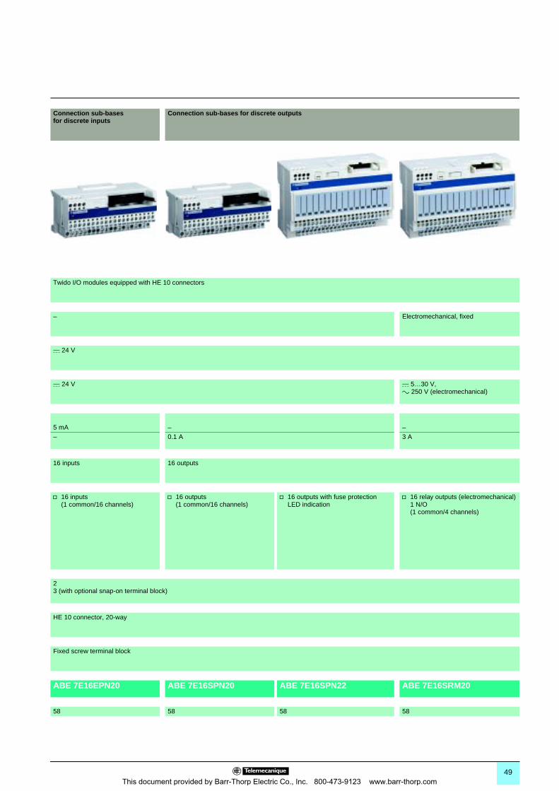
0
Connection sub-bases for discrete inputs
Connection sub-bases for discrete outputs
Twido I/O modules equipped with HE 10 connectors
– Electromechanical, fixed
c 24 V
c 24 V c 5…30 V,a 250 V (electromechanical)
5 mA – –– 0.1 A 3 A
16 inputs 16 outputs
v 16 inputs (1 common/16 channels)
v 16 outputs (1 common/16 channels)
v 16 outputs with fuse protectionLED indication
v 16 relay outputs (electromechanical) 1 N/O (1 common/4 channels)
23 (with optional snap-on terminal block)
HE 10 connector, 20-way
Fixed screw terminal block
ABE 7E16EPN20 ABE 7E16SPN20 ABE 7E16SPN22 ABE 7E16SRM20
58 58 58 58
49This document provided by Barr-Thorp Electric Co., Inc. 800-473-9123 www.barr-thorp.com
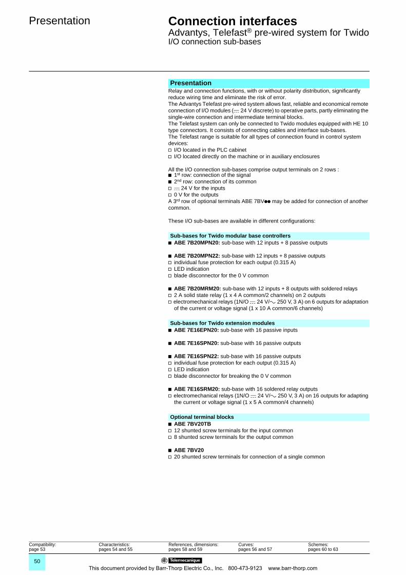
Presentation Connection interfaces 0
Advantys, Telefast® pre-wired system for TwidoI/O connection sub-bases
Relay and connection functions, with or without polarity distribution, significantly reduce wiring time and eliminate the risk of error.The Advantys Telefast pre-wired system allows fast, reliable and economical remote connection of I/O modules (c 24 V discrete) to operative parts, partly eliminating the single-wire connection and intermediate terminal blocks.The Telefast system can only be connected to Twido modules equipped with HE 10 type connectors. It consists of connecting cables and interface sub-bases.The Telefast range is suitable for all types of connection found in control system devices:v I/O located in the PLC cabinetv I/O located directly on the machine or in auxiliary enclosures
All the I/O connection sub-bases comprise output terminals on 2 rows :b 1st row: connection of the signalb 2nd row: connection of its commonv c 24 V for the inputsv 0 V for the outputsA 3rd row of optional terminals ABE 7BVpp may be added for connection of another common.
These I/O sub-bases are available in different configurations:
b ABE 7B20MPN20: sub-base with 12 inputs + 8 passive outputs
b ABE 7B20MPN22: sub-base with 12 inputs + 8 passive outputsv individual fuse protection for each output (0.315 A)v LED indicationv blade disconnector for the 0 V common
b ABE 7B20MRM20: sub-base with 12 inputs + 8 outputs with soldered relaysv 2 A solid state relay (1 x 4 A common/2 channels) on 2 outputsv electromechanical relays (1N/O c 24 V/a 250 V, 3 A) on 6 outputs for adaptation
of the current or voltage signal (1 x 10 A common/6 channels)
b ABE 7E16EPN20: sub-base with 16 passive inputs
b ABE 7E16SPN20: sub-base with 16 passive outputs
b ABE 7E16SPN22: sub-base with 16 passive outputsv individual fuse protection for each output (0.315 A)v LED indicationv blade disconnector for breaking the 0 V common
b ABE 7E16SRM20: sub-base with 16 soldered relay outputsv electromechanical relays (1N/O c 24 V/a 250 V, 3 A) on 16 outputs for adapting
the current or voltage signal (1 x 5 A common/4 channels)
b ABE 7BV20TBv 12 shunted screw terminals for the input commonv 8 shunted screw terminals for the output common
b ABE 7BV20v 20 shunted screw terminals for connection of a single common
Presentation
Sub-bases for Twido modular base controllers
Sub-bases for Twido extension modules
Optional terminal blocks
Compatibility:page 53
Characteristics: pages 54 and 55
References, dimensions:pages 58 and 59
Curves:pages 56 and 57
Schemes:pages 60 to 63
50This document provided by Barr-Thorp Electric Co., Inc. 800-473-9123 www.barr-thorp.com
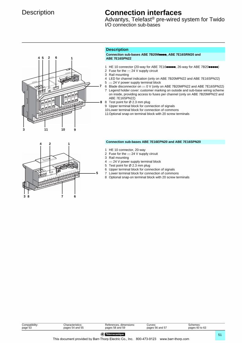
Description Connection interfaces 0
Advantys, Telefast® pre-wired system for TwidoI/O connection sub-bases
1 HE 10 connector, 20-way2 Fuse for the c 24 V supply circuit3 Rail mounting4 c 24 V power supply terminal block5 Test point for Ø 2.3 mm plug6 Upper terminal block for connection of signals7 Lower terminal block for connection of commons8 Optional snap-on terminal block with 20 screw terminals
DescriptionConnection sub-bases ABE 7B20Mpppp, ABE 7E16SRM20 and ABE 7E16SPN22
1 HE 10 connector (20-way for ABE 7E16ppppp, 26-way for ABE 7B20ppppp)2 Fuse for the c 24 V supply circuit3 Rail mounting4 LED for channel indication (only on ABE 7B20MPN22 and ABE 7E16SPN22)5 c 24 V power supply terminal block6 Blade disconnector on c 0 V (only on ABE 7B20MPN22 and ABE 7E16SPN22)7 Legend holder cover: customer marking on outside and sub-base wiring scheme
on inside, providing access to fuses per channel (only on ABE 7B20MPN22 and ABE 7E16SPN22)
8 Test point for Ø 2.3 mm plug9 Upper terminal block for connection of signals10Lower terminal block for connection of commons11Optional snap-on terminal block with 20 screw terminals
Connection sub-bases ABE 7E16EPN20 and ABE 7E16SPN20
7
8
162
910113
54
124
3 78 6
5
Compatibility:page 53
Characteristics: pages 54 and 55
References, dimensions:pages 58 and 59
Curves:pages 56 and 57
Schemes:pages 60 to 63
51This document provided by Barr-Thorp Electric Co., Inc. 800-473-9123 www.barr-thorp.com
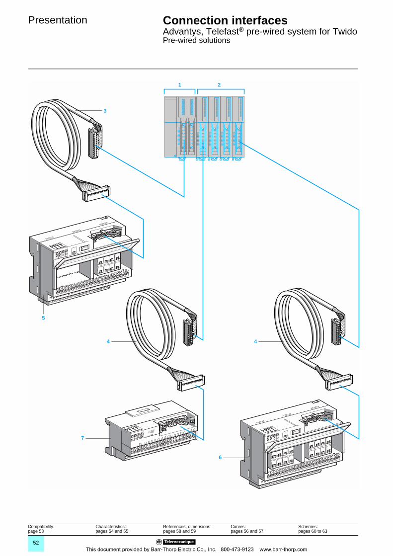
Presentation Connection interfaces 0
Advantys, Telefast® pre-wired system for TwidoPre-wired solutions
1 2
3
4 4
7
6
5
Compatibility:page 53
Characteristics: pages 54 and 55
References, dimensions:pages 58 and 59
Curves:pages 56 and 57
Schemes:pages 60 to 63
52This document provided by Barr-Thorp Electric Co., Inc. 800-473-9123 www.barr-thorp.com
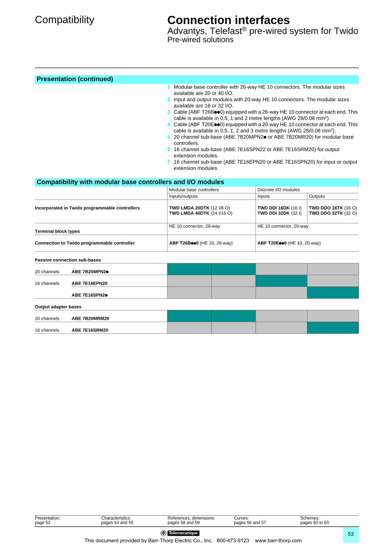
Compatibility Connection interfaces 0
Advantys, Telefast® pre-wired system for TwidoPre-wired solutions
Presentation (continued)1 Modular base controller with 26-way HE 10 connectors. The modular sizes
available are 20 or 40 I/O.2 Input and output modules with 20-way HE 10 connectors. The modular sizes
available are 16 or 32 I/O.3 Cable (ABF T26Bpp0) equipped with a 26-way HE 10 connector at each end. This
cable is available in 0.5, 1 and 2 metre lengths (AWG 28/0.08 mm2).4 Cable (ABF T20Epp0) equipped with a 20-way HE 10 connector at each end. This
cable is available in 0.5, 1, 2 and 3 metre lengths (AWG 28/0.08 mm2).5 20 channel sub-base (ABE 7B20MPN2p or ABE 7B20MR20) for modular base
controllers.6 16 channel sub-base (ABE 7E16SPN22 or ABE 7E16SRM20) for output
extension modules.7 16 channel sub-base (ABE 7E16EPN20 or ABE 7E16SPN20) for input or output
extension modules.
Compatibility with modular base controllers and I/O modulesModular base controllers Discrete I/O modulesInputs/outputs Inputs Outputs
Incorporated in Twido programmable controllers TWD LMDA 20DTK (12 I/8 O)TWD LMDA 40DTK (24 I/16 O)
TWD DDI 16DK (16 I)TWD DDI 32DK (32 I)
TWD DDO 16TK (16 O)TWD DDO 32TK (32 O)
Terminal block typesHE 10 connector, 26-way HE 10 connector, 20-way
Connection to Twido programmable controller ABF T26Bpp0 (HE 10, 26-way) ABF T20Epp0 (HE 10, 20-way)
Passive connection sub-bases
20 channels ABE 7B20MPN2p
16 channels ABE 7E16EPN20
ABE 7E16SPN2p
Output adapter bases
20 channels ABE 7B20MRM20
16 channels ABE 7E16SRM20
Presentation:page 52
Characteristics: pages 54 and 55
References, dimensions:pages 58 and 59
Curves:pages 56 and 57
Schemes:pages 60 to 63
53This document provided by Barr-Thorp Electric Co., Inc. 800-473-9123 www.barr-thorp.com
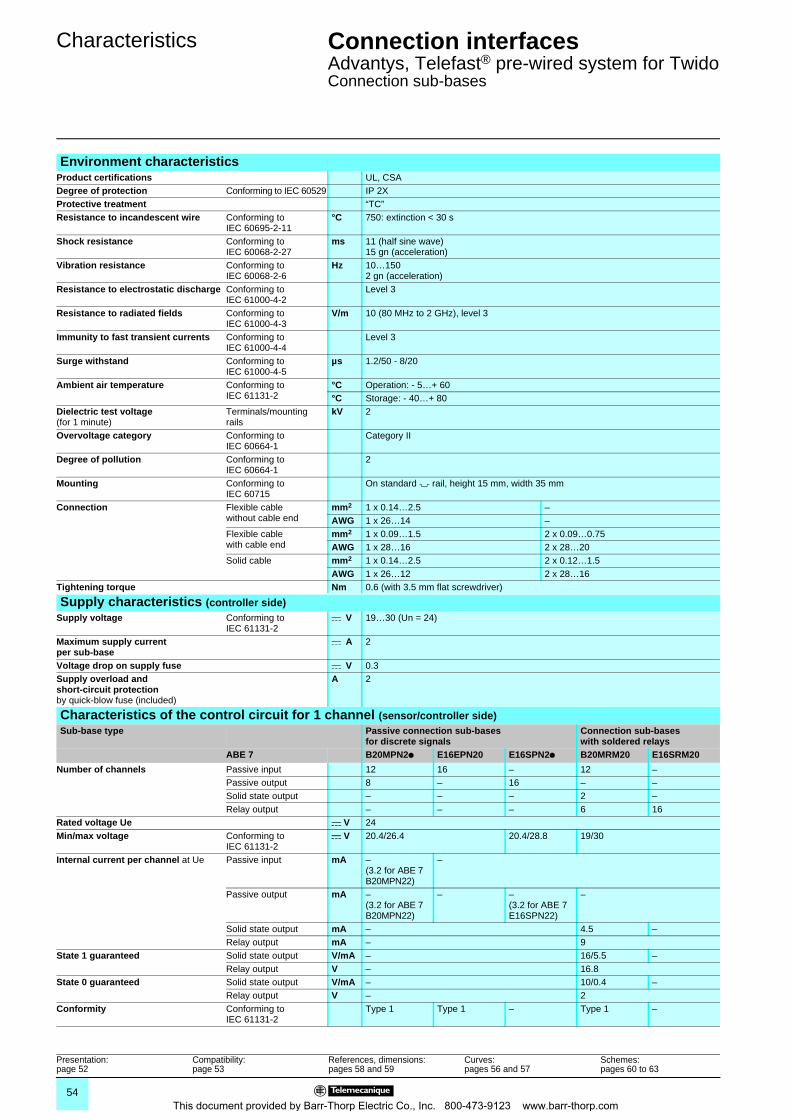
Characteristics Connection interfaces 0
Advantys, Telefast® pre-wired system for TwidoConnection sub-bases
Environment characteristicsProduct certifications UL, CSADegree of protection Conforming to IEC 60529 IP 2XProtective treatment “TC”Resistance to incandescent wire Conforming to
IEC 60695-2-11°C 750: extinction < 30 s
Shock resistance Conforming to IEC 60068-2-27
ms 11 (half sine wave)15 gn (acceleration)
Vibration resistance Conforming to IEC 60068-2-6
Hz 10…1502 gn (acceleration)
Resistance to electrostatic discharge Conforming toIEC 61000-4-2
Level 3
Resistance to radiated fields Conforming to IEC 61000-4-3
V/m 10 (80 MHz to 2 GHz), level 3
Immunity to fast transient currents Conforming to IEC 61000-4-4
Level 3
Surge withstand Conforming to IEC 61000-4-5
µs 1.2/50 - 8/20
Ambient air temperature Conforming to IEC 61131-2
°C Operation: - 5…+ 60°C Storage: - 40…+ 80
Dielectric test voltage(for 1 minute)
Terminals/mounting rails
kV 2
Overvoltage category Conforming to IEC 60664-1
Category II
Degree of pollution Conforming to IEC 60664-1
2
Mounting Conforming to IEC 60715
On standard 7 rail, height 15 mm, width 35 mm
Connection Flexible cable without cable end
mm2 1 x 0.14…2.5 –AWG 1 x 26…14 –
Flexible cable with cable end
mm2 1 x 0.09…1.5 2 x 0.09…0.75AWG 1 x 28…16 2 x 28…20
Solid cable mm2 1 x 0.14…2.5 2 x 0.12…1.5AWG 1 x 26…12 2 x 28…16
Tightening torque Nm 0.6 (with 3.5 mm flat screwdriver)
Supply characteristics (controller side)Supply voltage Conforming to
IEC 61131-2c V 19…30 (Un = 24)
Maximum supply current per sub-base
c A 2
Voltage drop on supply fuse c V 0.3Supply overload and short-circuit protectionby quick-blow fuse (included)
A 2
Characteristics of the control circuit for 1 channel (sensor/controller side)Sub-base type Passive connection sub-bases
for discrete signalsConnection sub-bases with soldered relays
ABE 7 B20MPN2p E16EPN20 E16SPN2p B20MRM20 E16SRM20
Number of channels Passive input 12 16 – 12 –Passive output 8 – 16 – –Solid state output – – – 2 –Relay output – – – 6 16
Rated voltage Ue c V 24Min/max voltage Conforming to
IEC 61131-2c V 20.4/26.4 20.4/28.8 19/30
Internal current per channel at Ue Passive input mA –(3.2 for ABE 7B20MPN22)
–
Passive output mA –(3.2 for ABE 7B20MPN22)
– –(3.2 for ABE 7E16SPN22)
–
Solid state output mA – 4.5 –Relay output mA – 9
State 1 guaranteed Solid state output V/mA – 16/5.5 –Relay output V – 16.8
State 0 guaranteed Solid state output V/mA – 10/0.4 –Relay output V – 2
Conformity Conforming to IEC 61131-2
Type 1 Type 1 – Type 1 –
Presentation:page 52
Compatibility: page 53
References, dimensions:pages 58 and 59
Curves:pages 56 and 57
Schemes:pages 60 to 63
54This document provided by Barr-Thorp Electric Co., Inc. 800-473-9123 www.barr-thorp.com
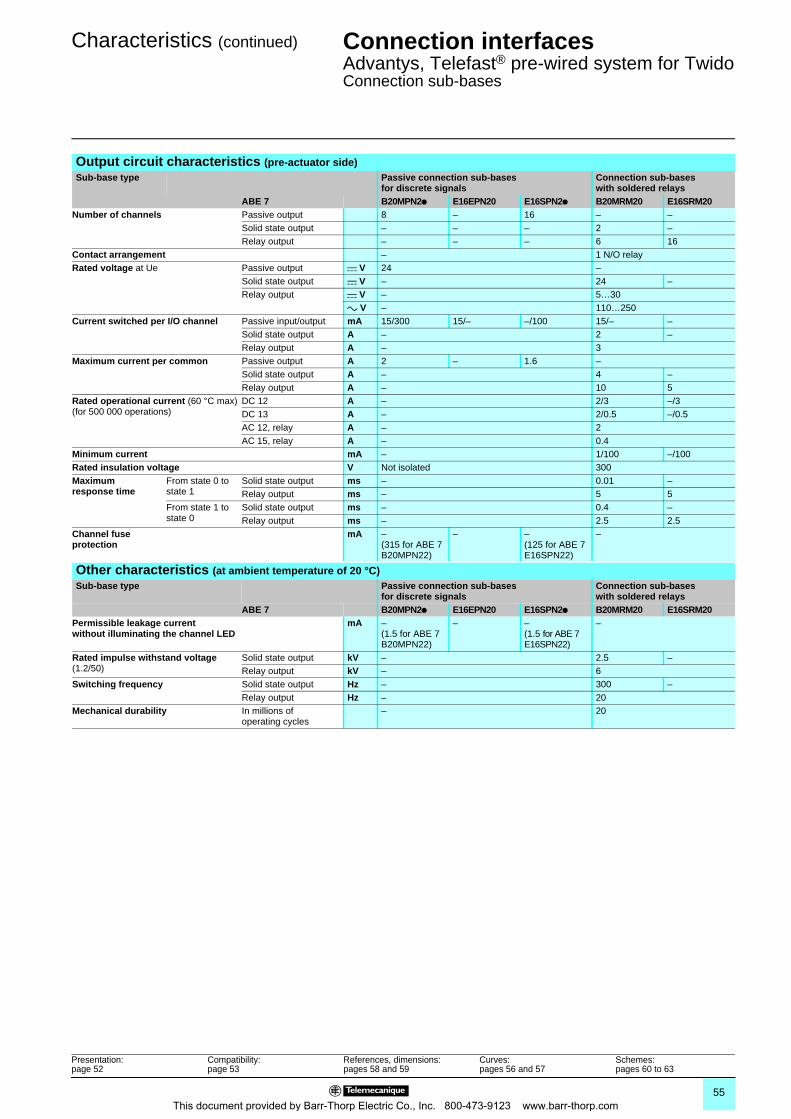
Characteristics (continued) Connection interfaces 0
Advantys, Telefast® pre-wired system for TwidoConnection sub-bases
Output circuit characteristics (pre-actuator side)Sub-base type Passive connection sub-bases
for discrete signalsConnection sub-bases with soldered relays
ABE 7 B20MPN2p E16EPN20 E16SPN2p B20MRM20 E16SRM20Number of channels Passive output 8 – 16 – –
Solid state output – – – 2 –Relay output – – – 6 16
Contact arrangement – 1 N/O relayRated voltage at Ue Passive output c V 24 –
Solid state output c V – 24 –Relay output c V – 5…30
a V – 110…250Current switched per I/O channel Passive input/output mA 15/300 15/– –/100 15/– –
Solid state output A – 2 –Relay output A – 3
Maximum current per common Passive output A 2 – 1.6 –Solid state output A – 4 –Relay output A – 10 5
Rated operational current (60 °C max)(for 500 000 operations)
DC 12 A – 2/3 –/3DC 13 A – 2/0.5 –/0.5AC 12, relay A – 2AC 15, relay A – 0.4
Minimum current mA – 1/100 –/100Rated insulation voltage V Not isolated 300Maximum response time
From state 0 to state 1
Solid state output ms – 0.01 –Relay output ms – 5 5
From state 1 to state 0
Solid state output ms – 0.4 –Relay output ms – 2.5 2.5
Channel fuse protection
mA –(315 for ABE 7B20MPN22)
– –(125 for ABE 7E16SPN22)
–
Other characteristics (at ambient temperature of 20 °C)Sub-base type Passive connection sub-bases
for discrete signalsConnection sub-bases with soldered relays
ABE 7 B20MPN2p E16EPN20 E16SPN2p B20MRM20 E16SRM20Permissible leakage current without illuminating the channel LED
mA –(1.5 for ABE 7B20MPN22)
– –(1.5 for ABE 7E16SPN22)
–
Rated impulse withstand voltage (1.2/50)
Solid state output kV – 2.5 –Relay output kV – 6
Switching frequency Solid state output Hz – 300 –Relay output Hz – 20
Mechanical durability In millions of operating cycles
– 20
Presentation:page 52
Compatibility: page 53
References, dimensions:pages 58 and 59
Curves:pages 56 and 57
Schemes:pages 60 to 63
55This document provided by Barr-Thorp Electric Co., Inc. 800-473-9123 www.barr-thorp.com
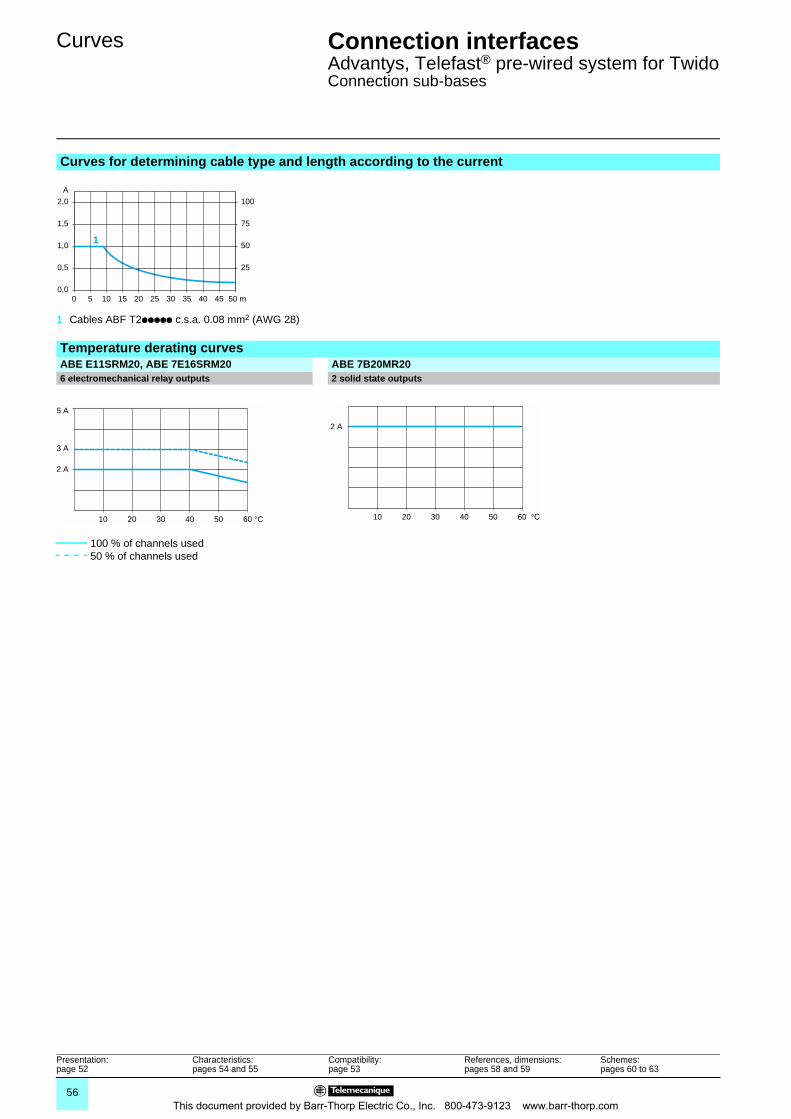
Curves Connection interfaces 0
Advantys, Telefast® pre-wired system for TwidoConnection sub-bases
Curves for determining cable type and length according to the current
1 Cables ABF T2ppppp c.s.a. 0.08 mm2 (AWG 28)
Temperature derating curvesABE E11SRM20, ABE 7E16SRM20 ABE 7B20MR206 electromechanical relay outputs 2 solid state outputs
100 % of channels used50 % of channels used
00,0
0,5
1,0
1,5
2,0A
25
50
75
100
50 m205
1
4515 25 30 403510
5 A
3 A
2 A
60 °C5040302010
2 A
5040302010
Presentation:page 52
Characteristics:pages 54 and 55
Compatibility: page 53
References, dimensions:pages 58 and 59
Schemes:pages 60 to 63
56This document provided by Barr-Thorp Electric Co., Inc. 800-473-9123 www.barr-thorp.com
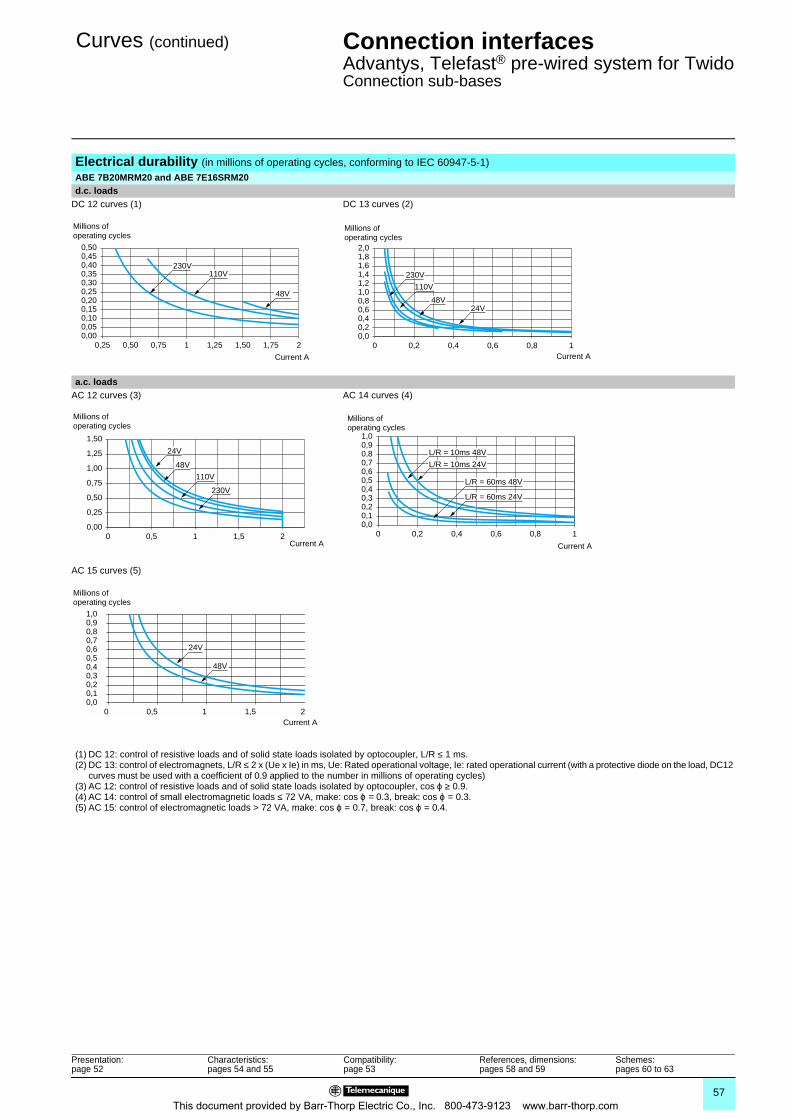
Curves (continued) Connection interfaces 0
Advantys, Telefast® pre-wired system for TwidoConnection sub-bases
Electrical durability (in millions of operating cycles, conforming to IEC 60947-5-1)ABE 7B20MRM20 and ABE 7E16SRM20d.c. loads
DC 12 curves (1) DC 13 curves (2)
a.c. loadsAC 12 curves (3) AC 14 curves (4)
AC 15 curves (5)
(1) DC 12: control of resistive loads and of solid state loads isolated by optocoupler, L/R ≤ 1 ms.(2) DC 13: control of electromagnets, L/R ≤ 2 x (Ue x Ie) in ms, Ue: Rated operational voltage, Ie: rated operational current (with a protective diode on the load, DC12
curves must be used with a coefficient of 0.9 applied to the number in millions of operating cycles)(3) AC 12: control of resistive loads and of solid state loads isolated by optocoupler, cos ϕ ≥ 0.9.(4) AC 14: control of small electromagnetic loads ≤ 72 VA, make: cos ϕ = 0.3, break: cos ϕ = 0.3.(5) AC 15: control of electromagnetic loads > 72 VA, make: cos ϕ = 0.7, break: cos ϕ = 0.4.
0,25 1,751,500,75 1 21,250,500,000,050,100,150,200,250,300,350,400,450,50
110V
48V
230V
Millions of operating cycles
Current A
0 0,80,4 10,60,20,00,20,40,60,81,01,21,41,61,82,0
230V
110V
24V48V
Millions of operating cycles
Current A
00,00
0,25
1,50
1,25
1,00
0,75
0,50
21 1,50,5
24V
48V
110V
230V
Millions of operating cycles
Current A0
0,00,10,20,3
1,00,90,80,70,60,50,4
10,4 0,60,2 0,8
L/R = 10ms 24V
L/R = 10ms 48V
L/R = 60ms 48V
L/R = 60ms 24V
Millions of operating cycles
Current A
00,00,10,20,3
1,00,90,80,70,60,50,4
21 1,50,5
24V
48V
Millions of operating cycles
Current A
Presentation:page 52
Characteristics:pages 54 and 55
Compatibility: page 53
References, dimensions:pages 58 and 59
Schemes:pages 60 to 63
57This document provided by Barr-Thorp Electric Co., Inc. 800-473-9123 www.barr-thorp.com
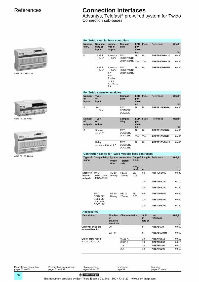
References Connection interfaces 0
Advantys, Telefast® pre-wired system for TwidoConnection sub-bases
For Twido modular base controllersNumber of I/O
Number, type of input
Number, type of output
Compati-bility
LED per chan-nel
Fuse Reference Weight
kg20 12, sink
c 24 V8, sourcec 24 V
TWDLMDA20DTK/LMDA40DTK
No No ABE7B20MPN20 0.430
Yes Yes ABE7B20MPN22 0.430
12, sink c 24 V
2, sourcec 24 V, 2 Aand 6, relayc 24/a 250 V, 3 A
TWDLMDA20DTK/LMDA40DTK
No No ABE7B20MRM20 0.430
For Twido extension modulesNumber ofinputs
Type of input
Compati-bility
LED per chan-nel
Fuse Reference Weight
kg16 Sink
c 24 VTWDDDI16DK/DDI32DK
No No ABE7E16EPN20 0.430
Number of outputs
Typeof output
Compati-bility
LED per chan-nel
Fuse Reference Weight
kg16 Source
c 24 VTWDDDO16TK/DDO32TK
No No ABE7E16SPN20 0.450
Yes Yes ABE7E16SPN22 0.450
Relayc 24/a 250 V, 3 A
TWDDDO16TK/DDO32TK
No No ABE7E16SRM20 0.430
Connection cables for Twido modular base controllersType of signal
Compatibility Type of connection Gauge/C.s.a.
Length Reference WeightTwido side
Telefast side
AWG/mm2 m kg
Discrete inputs/outputs
TWDLMDA20DTK/LMDA40DTK
HE 1026-way
HE 1026-way
28/0.08
0.5 ABFT26B050 0.080
1.0 ABFT26B100 0.110
2.0 ABFT26B200 0.180
TWDDDI16DK/DDI32DK/DDO16TK/DDO32TK
HE 1020-way
HE 1020-way
28/0.08
0.5 ABFT20E050 0.060
1.0 ABFT20E100 0.080
2.0 ABFT20E200 0.140
ABE 7B20MPN20
ABE 7E16EPN20
ABE 7E16SRM20
AccessoriesDescription Number
of shunted terminals
Characteristics Sold in lots of
Unit reference
Weight
kgOptional snap-on terminal blocks
20 – 5 ABE7BV20 0.060
12 + 8 – 5 ABE7BV20TB 0.060
Quick-blow fuses5 x 20, 250 V, UL
– 0.125 A 10 ABE7FU012 0.0100.315 A 10 ABE7FU030 0.0101 A 10 ABE7FU100 0.0102 A 10 ABE7FU200 0.010
Presentation, description:pages 50 and 51
Presentation, compatibility:pages 52 and 53
Characteristics:pages 54 and 55
Dimensions:page 59
Schemes:pages 60 to 63
58This document provided by Barr-Thorp Electric Co., Inc. 800-473-9123 www.barr-thorp.com
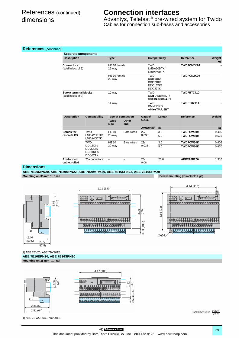
References (continued),
dimensionsConnection interfaces 0
Advantys, Telefast® pre-wired system for TwidoCables for connection sub-bases and accessories
References (continued)
Separate componentsDescription Type Compatibility Reference Weight
kgConnectors(sold in lots of 5)
HE 10 female26-way
TWDLMDA20DTK/LMDA40DTK
TWDFCN2K26 –
HE 10 female20-way
TWDDDI16DK/DDI32DK/DDO16TK/DDO32TK
TWDFCN2K20 –
Screw terminal blocks(sold in lots of 2)
10-way TWDDDIpDT/DAI8DT/DDO8pT/DRApRT
TWDFBT2T10 –
11-way TWDDMM8DRT/AMIppT/ARI8HT
TWDFTB2T11 –
Description Compatibility Type of connection Gauge/C.s.a.
Length Reference WeightTwido side
Other end
AWG/mm2 m kgCables for discrete I/O
TWDLMDA20DTK/LMDA40DTK
HE 1026-way
Bare wires 22/0.035
3.0 TWDFCW30M 0.4055.0 TWDFCW50M 0.670
TWDDDI16DK/DDI32DK/DDO16TK/DDO32TK
HE 1020-way
Bare wires 22/0.035
3.0 TWDFCW30K 0.4055.0 TWDFCW50K 0.670
Pre-formed cable, rolled
20 conductors – – 28/0.08
20.0 ABFC20R200 1.310
DimensionsABE 7B20MPN20, ABE 7B20MPN22, ABE 7B20MRM20, ABE 7E16SPN22, ABE 7E16SRM20Mounting on 35 mm 5 rail Screw mounting (retractable lugs)
(1) ABE 7BV20, ABE 7BV20TB.
ABE 7E16EPN20, ABE 7E16SPN20Mounting on 35 mm 5 rail
(1) ABE 7BV20, ABE 7BV20TB.
2xØ4
3.26
(83)
3.66
(93
)
0.53
(13
.5)
1.63
(41.
5)
2.46(62.5) 2.65
(67.5)
5.11 (130)4.44 (113)
(1)
2.36 (60)
2.51 (64)
0.94
(24)
4.17 (106)
1.92
(49)
0.53
(13
.5)
(1)
Dual Dimensions inches(mm)
59This document provided by Barr-Thorp Electric Co., Inc. 800-473-9123 www.barr-thorp.com
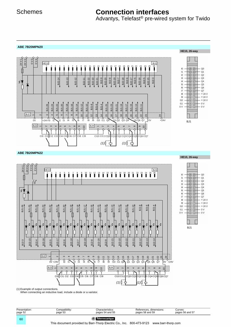
Schemes Connection interfaces 0
Advantys, Telefast® pre-wired system for Twido
ABE 7B20MPN20 HE10, 26-way
ABE 7B20MPN22HE10, 26-way
(1) Example of output connections. When connecting an inductive load, include a diode or a varistor.
1
1 2 3 4 5 6 7 8 9 10 11 12 13 14 15 16 17 18 19 20 21 22 23 24 25 26
2 3 4 5 6 7 8 9 10 11 12 13 14 15 16 17 18 19 20 21 22 23 24
24 V
-1
24 V
-2
0 V
-3
0 V
-4
HE10 BJ1
BJ2
1 2 3 4 5 6 7 8 9 10 1 2 3 4 5 6 7 8 9 10
BJ3 BJ4
BJ1
-26
BJ1
-24
BJ1
-22
BJ1
-20
BJ1
-18
BJ1
-16
BJ1
-14
BJ1
-12
BJ1
-10
BJ1
-25
BJ1
-23
BJ1
-21
BJ1
-19
BJ1
-17
BJ1
-15
BJ1
-13
BJ1
-11
BJ1
-8
BJ1
-6
BJ1
-4
BJ2
-14
BJ2
-13
BJ2
-12
BJ2
-11
BJ2
-22
BJ2
-10
BJ2
-21
BJ2
-9
BJ2
-20
BJ2
-8
BJ2
-19
BJ2
-7
BJ2
-18
BJ2
-6
BJ2
-17
BJ2
-5
BJ2
-16
BJ2
-5
BJ2
-15
BJ2
-3
(1)
CI0 CI1 CI2 CI3 CI4 CI5 CI6 CI7 CI8 CI9 CI10 CI11 CQ0 CQ1 CQ2 CQ3CQ4 CQ5 CQ6 CQ7
(1)
0V +24V I0 I1 I2 I3 I4 I5 I6 I7 I8 I9 I10 I11 Q0 Q1Q2 Q3 Q4 Q5 Q6 Q7 0V +24V
14 13
12 11
10 9
8 7
6 5
16 15
18 17
20 19
22 21
24 23
Q3Q4Q5Q6Q7+ 24 V+ 24 V+ 24 V
I3I4
Q1Q2
I1I2
I5I6I7I8I9
I10
26 25 Q0I0
4 3
2 1
0 V0 V
I110 V
BJ1
1
1 2 3 4 5 6 7 8 9 10 11 12 13 14 15 16 17 18 19 20 21 22 23 24 25 26
2 3 4 5 6 7 8 9 10 11 12 13 14 15 16 17 18 19 20 21 22 23 24
24 V
-1
24 V
-2
0 V
-3
0 V
-4
HE10 BJ1
BJ2
1 2 3 4 5 6 7 8 9 10 1 2 3 4 5 6 7 8 9 10
BJ3 BJ4
BJ1
-25
BJ1
-24
BJ1
-23
BJ1
-22
BJ1
-21
BJ1
-20
BJ1
-19
BJ1
-18
BJ1
-17
BJ1
-16
BJ1
-15
BJ1
-14
BJ1
-13
BJ1
-12
BJ1
-11
BJ1
-10
BJ1
-8
BJ1
-6
BJ1
-4
BJ1
-26
BJ2
-15
BJ2
-4
BJ2
-16
BJ2
-5
BJ2
-17
BJ2
-6
BJ2
-18
BJ2
-7
BJ2
-19
BJ2
-8
BJ2
-20
BJ2
-9
BJ2
-21
BJ2
-10
BJ2
-22
BJ2
-11
BJ2
-12
BJ2
-13
BJ2
-14
BJ2
-3
CI0 CI1 CI2 CI3 CI4 CI5 CI6 CI7 CI8 CI9 CI10 CI11 CQ0 CQ1 CQ2 CQ3 CQ4 CQ5 CQ6 CQ7
0V +24V I0 I1 I2 I3 I4 I5 I6 I7 I8 I9 I10 I11 Q0 Q1 Q2 Q3 Q4 Q5 Q6 Q7 0V +24V
(1) (1)
14 13
12 11
10 9
8 7
6 5
16 15
18 17
20 19
22 21
24 23
Q3Q4Q5Q6Q7+ 24 V+ 24 V+ 24 V
I3I4
Q1Q2
I1I2
I5I6I7I8I9
I10
26 25 Q0I0
4 3
2 1
0 V0 V
I110 V
BJ1
Presentation:page 52
Compatibility: page 53
Characteristics:pages 54 and 55
References, dimensions:pages 58 and 59
Curves:pages 56 and 57
60This document provided by Barr-Thorp Electric Co., Inc. 800-473-9123 www.barr-thorp.com
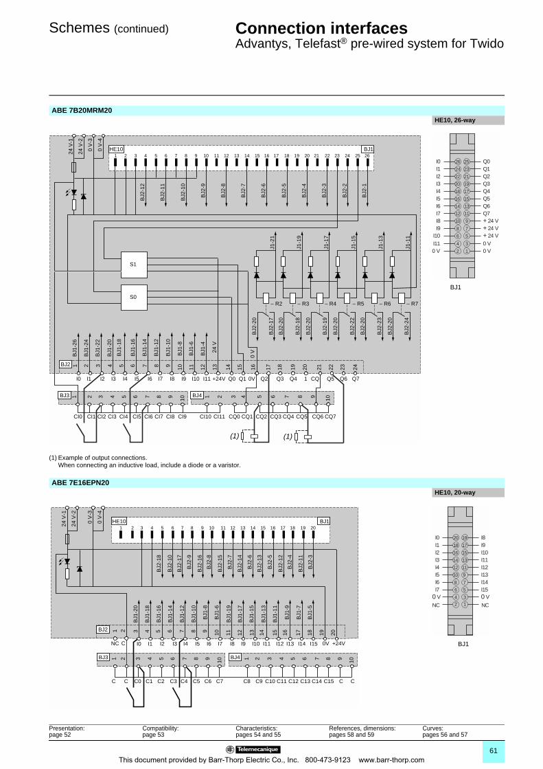
Schemes (continued) Connection interfaces 0
Advantys, Telefast® pre-wired system for Twido
ABE 7B20MRM20HE10, 26-way
(1) Example of output connections. When connecting an inductive load, include a diode or a varistor.
ABE 7E16EPN20 HE10, 20-way
1
1 2 3 4 5 6 7 8 9 10 11 12 13 14 15 16 17 18 19 20 21 22 23 24 25 26
2 3 4 5 6 7 8 9 10 11 12 13 14 15 16 17 18 19 20 21 22 23 24
24 V
-1
24 V
-2
0 V
-3
0 V
-4
HE10
– R2 – R3 – R4 – R5 – R6 – R7
BJ1
BJ2
1 2 3 4 5 6 7 8 9 10 1 2 3 4 5 6 7 8 9 10
BJ3 BJ4
BJ1
-26
BJ2
-24
J1-1
1
BJ2
-20
BJ1
-24
BJ1
-22
BJ1
-20
BJ1
-18
BJ1
-16
BJ1
-14
BJ1
-12
BJ1
-10
BJ1
-8
BJ1
-6
BJ1
-4
24 V
0 V
BJ2
-23
J1-1
3
BJ2
-20
BJ2
-22
J1-1
5
BJ2
-20
BJ2
-19
J1-1
7
BJ2
-20
BJ2
-18
J1-1
9
BJ2
-20
BJ2
-17
J1-2
1
BJ2
-20
BJ2
-12
BJ2
-11
BJ2
-10
BJ2
-9
BJ2
-8
BJ2
-7
BJ2
-6
BJ2
-5
BJ2
-4
BJ2
-3
BJ2
-2
BJ2
-1
S1
S0
I0 I1 I2 I3 I4 I5 I6 I7 I8 I9 I10 I11 +24V Q0 Q1 Q2 Q3 Q4 1 CQ Q5 Q6 Q7
CI0 CI1 CI2 CI3 CI4 CI5 CI6 CI7 CI8 CI9 CI10 CI11 CQ0 CQ1 CQ2 CQ3 CQ4 CQ5 CQ6 CQ7
(1)(1)
0V
14 13
12 11
10 9
8 7
6 5
16 15
18 17
20 19
22 21
24 23
Q3Q4Q5Q6Q7+ 24 V+ 24 V+ 24 V
I3I4
Q1Q2
I1I2
I5I6I7I8I9
I10
26 25 Q0I0
4 3
2 1
0 V0 V
I110 V
BJ1
1
1 2 3 4 5 6 7 8 9 10 11 12 13 14 15 16 17 18 19 20
2 3 4 5 6 7 8 9 10 11 12 13 14 15 16 17 18 19 20
24 V
-1
24 V
-2
0 V
-3
0 V
-4
HE10 BJ1
BJ2
1 2 3 4 5 6 7 8 9 10 1 2 3 4 5 6 7 8 9 10
BJ3 BJ4
BJ1
-20
BJ1
-18
BJ1
-16
BJ1
-14
BJ1
-12
BJ1
-10
BJ1
-8
BJ1
-6
BJ1
-19
BJ1
-11
BJ1
-9
BJ1
-7
BJ1
-5
BJ1
-17
BJ1
-15
BJ1
-13
BJ2
-10
BJ2
-18
BJ2
-17
BJ2
-16
BJ2
-9
BJ2
-8
BJ2
-15
BJ2
-7
BJ2
-14
BJ2
-6
BJ2
-13
BJ2
-5
BJ2
-12
BJ2
-4
BJ2
-11
BJ2
-3
NC C I10I9I8I7I6I5I4I3I2I1I0 I11 I12 I13 I14 I15 0V +24V
C C C0 C1 C2 C3 C4 C5 C6 C7 C8 C9 C10 C11 C13 C15C12 C14 C C
8 7
6 5
4
2
3
1
10 9
12 11
14 13
16 15
18 17
I11I12I13I14I150 V0 V
NC NC
I3I4
I9I10
I1I2
I5I6I7
20 19 I8I0
BJ1
Presentation:page 52
Compatibility: page 53
Characteristics:pages 54 and 55
References, dimensions:pages 58 and 59
Curves:pages 56 and 57
61This document provided by Barr-Thorp Electric Co., Inc. 800-473-9123 www.barr-thorp.com
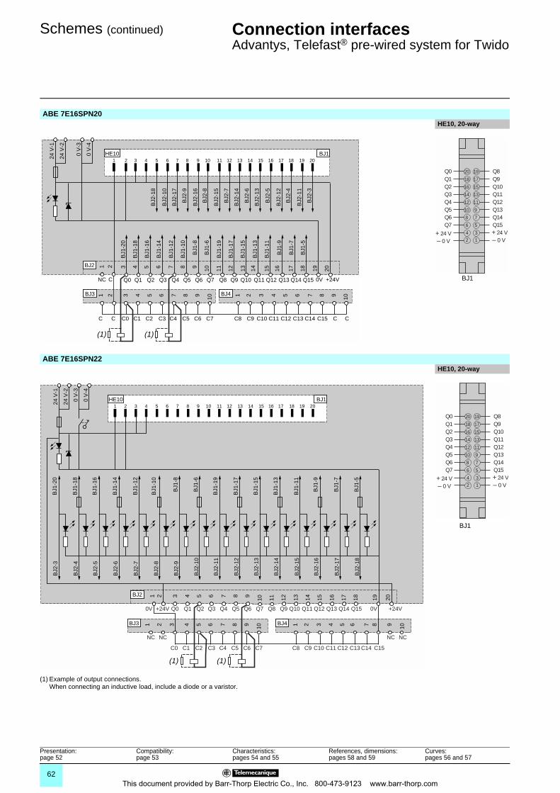
Schemes (continued) Connection interfaces 0
Advantys, Telefast® pre-wired system for Twido
ABE 7E16SPN20 HE10, 20-way
ABE 7E16SPN22HE10, 20-way
(1) Example of output connections. When connecting an inductive load, include a diode or a varistor.
1 2 3 4 5 6 7 8 9 10 11 12 13 14 15 16 17 18 19 20
24 V
-1
24 V
-2
0 V
-3
0 V
-4
HE10 BJ1
BJ2
-10
BJ2
-18
BJ2
-17
BJ2
-16
BJ2
-9
BJ2
-8
BJ2
-15
BJ2
-7
BJ2
-14
BJ2
-6
BJ2
-13
BJ2
-5
BJ2
-12
BJ2
-4
BJ2
-11
BJ2
-3
1 2 3 4 5 6 7 8 9 10 11 12 13 14 15 16 17 18 19 20
BJ2
1 2 3 4 5 6 7 8 9 10 1 2 3 4 5 6 7 8 9 10
BJ3 BJ4
BJ1
-20
BJ1
-18
BJ1
-16
BJ1
-14
BJ1
-12
BJ1
-10
BJ1
-8
BJ1
-6
BJ1
-19
BJ1
-11
BJ1
-9
BJ1
-7
BJ1
-5
BJ1
-17
BJ1
-15
BJ1
-13
NC C Q10Q9Q8Q7Q6Q5Q4Q3Q2Q1Q0 Q11 Q12 Q13 Q14 Q15 0V +24V
C C C0 C1 C2 C3 C4 C5 C6 C7 C8 C9 C10 C11 C13 C15C12 C14 C C
(1) (1)
BJ1
8 7
6 5
4
2
3
1
10 9
12 11
14 13
16 15
18 17
Q11Q12Q13Q14Q15
– 0 V – 0 V+ 24 V + 24 V
Q3Q4
Q9Q10
Q1Q2
Q5Q6Q7
20 19 Q8Q0
1
1 2 3 4 5 6 7 8 9 10 11 12 13 14 15 16 17 18 19 20
2 3 4 5 6 7 8 9
10 11 12 13 14 15 16 17 18 19 20
24 V
-1
24 V
-2
0 V
-3
0 V
-4
HE10 BJ1
BJ2
1 2 3 4 5 6 7 8 9 10 1 2 3 4 5 6 7 8 9 10
BJ3 BJ4
BJ1
-18
BJ1
-16
BJ1
-14
BJ1
-12
BJ1
-10
BJ1
-8
BJ1
-6
BJ1
-19
BJ1
-17
BJ1
-15
BJ1
-13
BJ1
-11
BJ1
-9
BJ1
-7
BJ1
-5
BJ1
-20
BJ2
-4
BJ2
-5
BJ2
-6
BJ2
-7
BJ2
-8
BJ2
-9
BJ2
-10
BJ2
-11
BJ2
-12
BJ2
-13
BJ2
-14
BJ2
-15
BJ2
-16
BJ2
-17
BJ2
-18
BJ2
-3
(1)(1)
0V +24V Q0 Q1 Q2 Q3 Q4 Q5 Q6 Q7 Q8 Q9 Q10 Q12Q11 Q14Q13 Q15 0V +24V
NC NC
C0 C1 C2 C3 C4 C5 C6 C7 C8 C9 C10 C12C11 C13 C14 C15
NC NC
8 7
6 5
4
2
3
1
10 9
12 11
14 13
16 15
18 17
Q11Q12Q13Q14Q15
– 0 V – 0 V+ 24 V + 24 V
Q3Q4
Q9Q10
Q1Q2
Q5Q6Q7
20 19 Q8Q0
BJ1
Presentation:page 52
Compatibility: page 53
Characteristics:pages 54 and 55
References, dimensions:pages 58 and 59
Curves:pages 56 and 57
62This document provided by Barr-Thorp Electric Co., Inc. 800-473-9123 www.barr-thorp.com
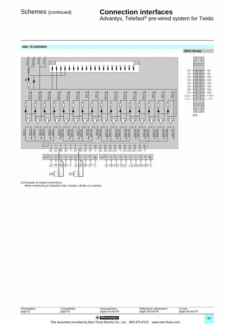
Schemes (continued) Connection interfaces 0
Advantys, Telefast® pre-wired system for Twido
ABE 7E16SRM20HE10, 20-way
(1) Example of output connections. When connecting an inductive load, include a diode or a varistor.
1 2 3 4 5 6 7 8 9 10 11 12 13 14 15 16 17 18 19 20HE10
1 2 3 4 5 6 7 8 9 10 11 12 13 14 15 16 17 18 19 20
24 V
-1
24 V
-2
0 V
-3
0 V
-4
BJ1
BJ2
1 2 3 4 5 6 7 8 9 10 1 2 3 4 5 6 7 8 9 10
BJ3 BJ4
BJ2
-19
BJ1
-5
BJ2
-20
BJ2
-18
BJ1
-7
BJ2
-20
BJ2
-17
BJ1
-9
BJ2
-20
BJ2
-16
BJ1
-11
BJ2
-20
BJ2
-14
BJ1
-13
BJ2
-15
BJ2
-13
BJ1
-15
BJ2
-15
BJ2
-12
BJ1
-17
BJ2
-15
BJ2
-11
BJ1
-19
BJ2
-15
BJ2
-9B
J1-6
BJ2
-10
BJ2
-8B
J1-8
BJ2
-10
BJ2
-7B
J1-1
0
BJ2
-10
BJ2
-6B
J1-1
2
BJ2
-10
BJ2
-4B
J1-1
4
BJ2
-5
BJ2
-3B
J1-1
6
BJ2
-5B
J2-2
BJ1
-18
BJ2
-5
BJ2
-1B
J1-2
0
BJ2
-5
Q0 Q1 Q2 Q3 1 Q4 Q5 Q6 Q7 2 Q8 Q9 Q10 Q11 3 Q12 Q13 Q14 Q15 4
C0 C1 C2 C3 C C4 C5 C6 C7 C C8 C9 C10 C11 C C12 C13 C14 C15 C
(1)(1)
8 7
6 5
4
2
3
1
10 9
12 11
14 13
16 15
18 17
Q11Q12Q13Q14Q15
– 0 V – 0 V+ 24 V + 24 V
Q3Q4
Q9Q10
Q1Q2
Q5Q6Q7
20 19 Q8Q0
BJ1
Presentation:page 52
Compatibility: page 53
Characteristics:pages 54 and 55
References, dimensions:pages 58 and 59
Curves:pages 56 and 57
63This document provided by Barr-Thorp Electric Co., Inc. 800-473-9123 www.barr-thorp.com
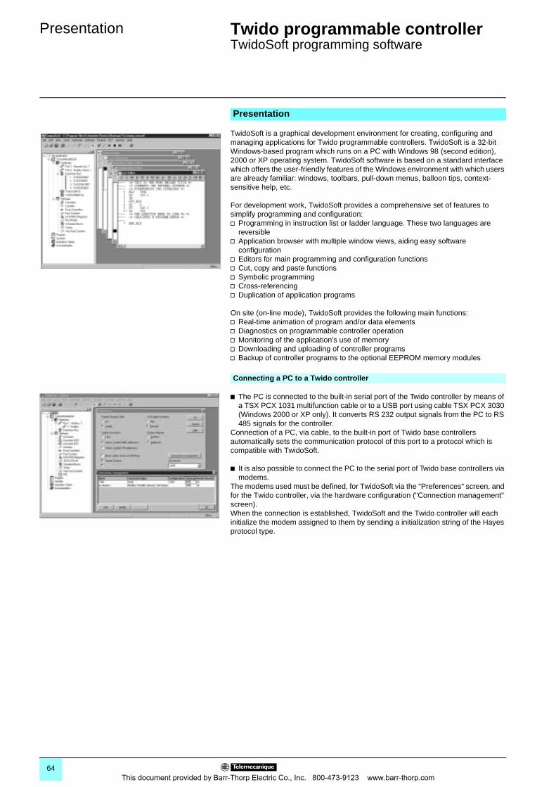
Presentation 0 Twido programmable controller 0
TwidoSoft programming software
TwidoSoft is a graphical development environment for creating, configuring and managing applications for Twido programmable controllers. TwidoSoft is a 32-bit Windows-based program which runs on a PC with Windows 98 (second edition), 2000 or XP operating system. TwidoSoft software is based on a standard interface which offers the user-friendly features of the Windows environment with which users are already familiar: windows, toolbars, pull-down menus, balloon tips, context-sensitive help, etc.
For development work, TwidoSoft provides a comprehensive set of features to simplify programming and configuration:v Programming in instruction list or ladder language. These two languages are
reversiblev Application browser with multiple window views, aiding easy software
configurationv Editors for main programming and configuration functionsv Cut, copy and paste functionsv Symbolic programmingv Cross-referencingv Duplication of application programs
On site (on-line mode), TwidoSoft provides the following main functions:v Real-time animation of program and/or data elementsv Diagnostics on programmable controller operationv Monitoring of the application's use of memoryv Downloading and uploading of controller programsv Backup of controller programs to the optional EEPROM memory modules
b The PC is connected to the built-in serial port of the Twido controller by means of a TSX PCX 1031 multifunction cable or to a USB port using cable TSX PCX 3030 (Windows 2000 or XP only). It converts RS 232 output signals from the PC to RS 485 signals for the controller.
Connection of a PC, via cable, to the built-in port of Twido base controllers automatically sets the communication protocol of this port to a protocol which is compatible with TwidoSoft.
b It is also possible to connect the PC to the serial port of Twido base controllers via modems.
The modems used must be defined, for TwidoSoft via the "Preferences" screen, and for the Twido controller, via the hardware configuration ("Connection management" screen). When the connection is established, TwidoSoft and the Twido controller will each initialize the modem assigned to them by sending a initialization string of the Hayes protocol type.
Presentation
Connecting a PC to a Twido controller
64This document provided by Barr-Thorp Electric Co., Inc. 800-473-9123 www.barr-thorp.com
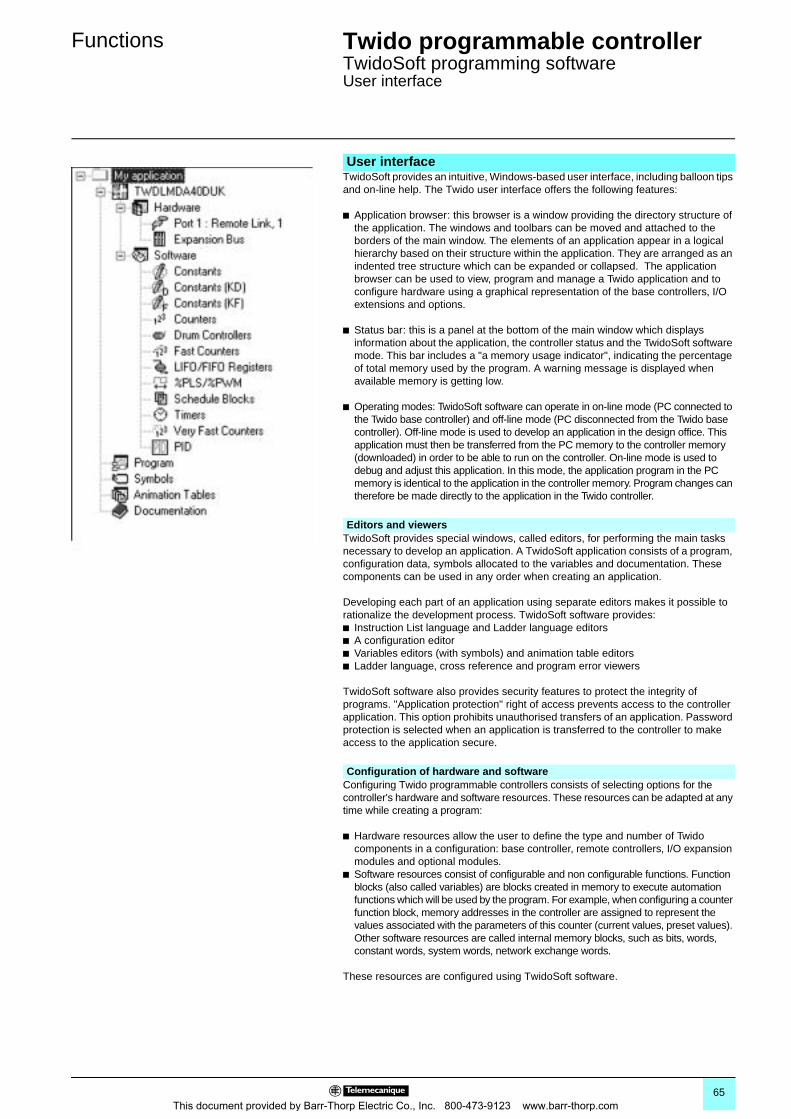
Functions 0 Twido programmable controller 0
TwidoSoft programming softwareUser interface
TwidoSoft provides an intuitive, Windows-based user interface, including balloon tips and on-line help. The Twido user interface offers the following features:
b Application browser: this browser is a window providing the directory structure of the application. The windows and toolbars can be moved and attached to the borders of the main window. The elements of an application appear in a logical hierarchy based on their structure within the application. They are arranged as an indented tree structure which can be expanded or collapsed. The application browser can be used to view, program and manage a Twido application and to configure hardware using a graphical representation of the base controllers, I/O extensions and options.
b Status bar: this is a panel at the bottom of the main window which displays information about the application, the controller status and the TwidoSoft software mode. This bar includes a "a memory usage indicator", indicating the percentage of total memory used by the program. A warning message is displayed when available memory is getting low.
b Operating modes: TwidoSoft software can operate in on-line mode (PC connected to the Twido base controller) and off-line mode (PC disconnected from the Twido base controller). Off-line mode is used to develop an application in the design office. This application must then be transferred from the PC memory to the controller memory (downloaded) in order to be able to run on the controller. On-line mode is used to debug and adjust this application. In this mode, the application program in the PC memory is identical to the application in the controller memory. Program changes can therefore be made directly to the application in the Twido controller.
TwidoSoft provides special windows, called editors, for performing the main tasks necessary to develop an application. A TwidoSoft application consists of a program, configuration data, symbols allocated to the variables and documentation. These components can be used in any order when creating an application.
Developing each part of an application using separate editors makes it possible to rationalize the development process. TwidoSoft software provides: b Instruction List language and Ladder language editorsb A configuration editorb Variables editors (with symbols) and animation table editorsb Ladder language, cross reference and program error viewers
TwidoSoft software also provides security features to protect the integrity of programs. "Application protection" right of access prevents access to the controller application. This option prohibits unauthorised transfers of an application. Password protection is selected when an application is transferred to the controller to make access to the application secure.
Configuring Twido programmable controllers consists of selecting options for the controller's hardware and software resources. These resources can be adapted at any time while creating a program:
b Hardware resources allow the user to define the type and number of Twido components in a configuration: base controller, remote controllers, I/O expansion modules and optional modules.
b Software resources consist of configurable and non configurable functions. Function blocks (also called variables) are blocks created in memory to execute automation functions which will be used by the program. For example, when configuring a counter function block, memory addresses in the controller are assigned to represent the values associated with the parameters of this counter (current values, preset values). Other software resources are called internal memory blocks, such as bits, words, constant words, system words, network exchange words.
These resources are configured using TwidoSoft software.
User interface
Editors and viewers
Configuration of hardware and software
65This document provided by Barr-Thorp Electric Co., Inc. 800-473-9123 www.barr-thorp.com
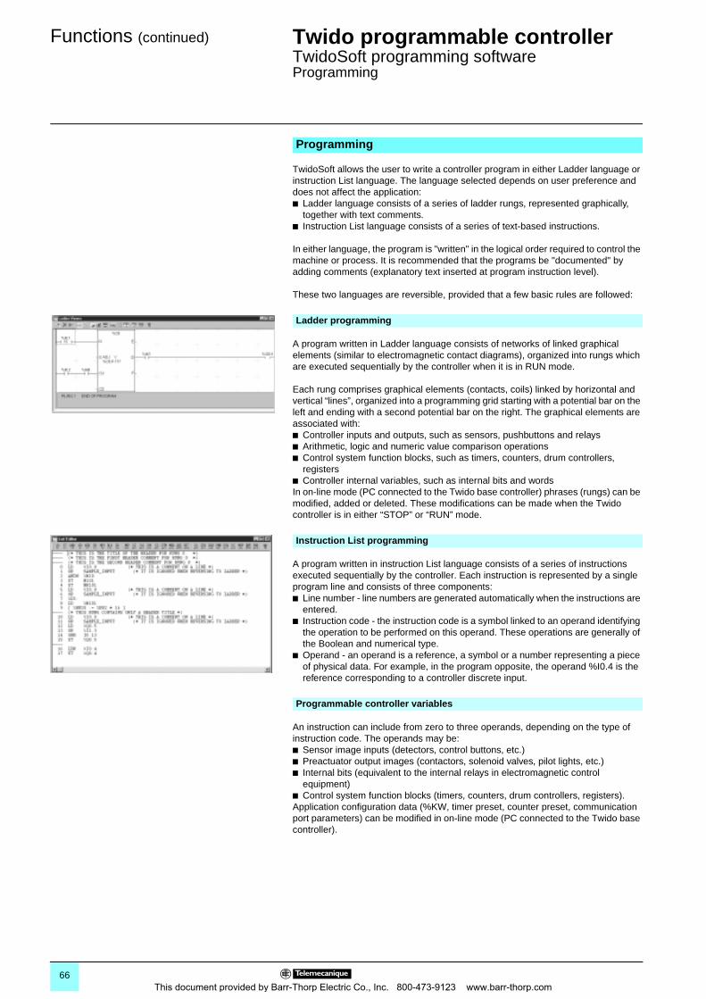
Functions (continued) 0 Twido programmable controller 0
TwidoSoft programming softwareProgramming
TwidoSoft allows the user to write a controller program in either Ladder language or instruction List language. The language selected depends on user preference and does not affect the application: b Ladder language consists of a series of ladder rungs, represented graphically,
together with text comments. b Instruction List language consists of a series of text-based instructions.
In either language, the program is "written" in the logical order required to control the machine or process. It is recommended that the programs be "documented" by adding comments (explanatory text inserted at program instruction level).
These two languages are reversible, provided that a few basic rules are followed:
A program written in Ladder language consists of networks of linked graphical elements (similar to electromagnetic contact diagrams), organized into rungs which are executed sequentially by the controller when it is in RUN mode.
Each rung comprises graphical elements (contacts, coils) linked by horizontal and vertical “lines”, organized into a programming grid starting with a potential bar on the left and ending with a second potential bar on the right. The graphical elements are associated with: b Controller inputs and outputs, such as sensors, pushbuttons and relaysb Arithmetic, logic and numeric value comparison operationsb Control system function blocks, such as timers, counters, drum controllers,
registersb Controller internal variables, such as internal bits and wordsIn on-line mode (PC connected to the Twido base controller) phrases (rungs) can be modified, added or deleted. These modifications can be made when the Twido controller is in either “STOP” or “RUN” mode.
A program written in instruction List language consists of a series of instructions executed sequentially by the controller. Each instruction is represented by a single program line and consists of three components:b Line number - line numbers are generated automatically when the instructions are
entered.b Instruction code - the instruction code is a symbol linked to an operand identifying
the operation to be performed on this operand. These operations are generally of the Boolean and numerical type.
b Operand - an operand is a reference, a symbol or a number representing a piece of physical data. For example, in the program opposite, the operand %I0.4 is the reference corresponding to a controller discrete input.
An instruction can include from zero to three operands, depending on the type of instruction code. The operands may be:b Sensor image inputs (detectors, control buttons, etc.)b Preactuator output images (contactors, solenoid valves, pilot lights, etc.)b Internal bits (equivalent to the internal relays in electromagnetic control
equipment)b Control system function blocks (timers, counters, drum controllers, registers).Application configuration data (%KW, timer preset, counter preset, communication port parameters) can be modified in on-line mode (PC connected to the Twido base controller).
Programming
Ladder programming
Instruction List programming
Programmable controller variables
66This document provided by Barr-Thorp Electric Co., Inc. 800-473-9123 www.barr-thorp.com
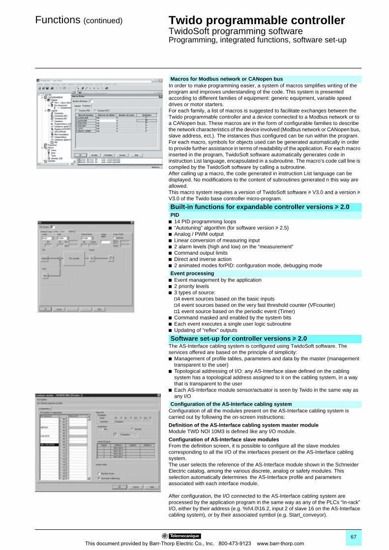
Functions (continued) 0 Twido programmable controller 0
TwidoSoft programming softwareProgramming, integrated functions, software set-up
In order to make programming easier, a system of macros simplifies writing of the program and improves understanding of the code. This system is presented according to different families of equipment: generic equipment, variable speed drives or motor starters.For each family, a list of macros is suggested to facilitate exchanges between the Twido programmable controller and a device connected to a Modbus network or to a CANopen bus. These macros are in the form of configurable families to describe the network characteristics of the device involved (Modbus network or CANopen bus, slave address, ect.). The instances thus configured can be run within the program. For each macro, symbols for objects used can be generated automatically in order to provide further assistance in terms of readability of the application. For each macro inserted in the program, TwidoSoft software automatically generates code in instruction List language, encapsulated in a subroutine. The macro’s code call line is compiled by the TwidoSoft software by calling a subroutine. After calling up a macro, the code generated in instruction List language can be displayed. No modifications to the content of subroutines generated n this way are allowed.This macro system requires a version of TwidoSoft software u V3.0 and a version u V3.0 of the Twido base controller micro-program.
b 14 PID programming loopsb “Autotuning” algorithm (for software version u 2.5)b Analog / PWM outputb Linear conversion of measuring inputb 2 alarm levels (high and low) on the “measurement”b Command output limitsb Direct and inverse actionb 2 animated modes forPID: configuration mode, debugging mode
b Event management by the applicationb 2 priority levelsb 3 types of source:
v4 event sources based on the basic inputsv4 event sources based on the very fast threshold counter (VFcounter)v1 event source based on the periodic event (Timer)
b Command masked and enabled by the system bitsb Each event executes a single user logic subroutineb Updating of “reflex” outputs
The AS-Interface cabling system is configured using TwidoSoft software. The services offered are based on the principle of simplicity:b Management of profile tables, parameters and data by the master (management
transparent to the user)b Topological addressing of I/O: any AS-Interface slave defined on the cabling
system has a topological address assigned to it on the cabling system, in a way that is transparent to the user
b Each AS-Interface module sensor/actuator is seen by Twido in the same way as any I/O
Configuration of all the modules present on the AS-Interface cabling system is carried out by following the on-screen instructions:
Definition of the AS-Interface cabling system master module Module TWD NOI 10M3 is defined like any I/O module.
Configuration of AS-Interface slave modulesFrom the definition screen, it is possible to configure all the slave modules corresponding to all the I/O of the interfaces present on the AS-Interface cabling system. The user selects the reference of the AS-Interface module shown in the Schneider Electric catalog, among the various discrete, analog or safety modules. This selection automatically determines the AS-Interface profile and parameters associated with each interface module.
After configuration, the I/O connected to the AS-Interface cabling system are processed by the application program in the same way as any of the PLCs “In-rack” I/O, either by their address (e.g. %I\4.0\16.2, input 2 of slave 16 on the AS-Interface cabling system), or by their associated symbol (e.g. Start_conveyor).
Macros for Modbus network or CANopen bus
Built-in functions for expandable controller versions u 2.0PID
Event processing
Software set-up for controller versions u 2.0
Configuration of the AS-Interface cabling system
67This document provided by Barr-Thorp Electric Co., Inc. 800-473-9123 www.barr-thorp.com
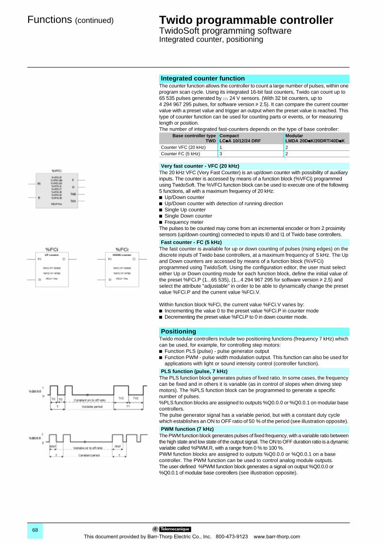
Functions (continued) 0 Twido programmable controller 0
TwidoSoft programming softwareIntegrated counter, positioning
The counter function allows the controller to count a large number of pulses, within one program scan cycle. Using its integrated 16-bit fast counters, Twido can count up to 65 535 pulses generated by c 24 V sensors. (With 32 bit counters, up to 4 294 967 295 pulses, for software version u 2.5). It can compare the current counter value with a preset value and trigger an output when the preset value is reached. This type of counter function can be used for counting parts or events, or for measuring length or position.The number of integrated fast-counters depends on the type of base controller:
The 20 kHz VFC (Very Fast Counter) is an up/down counter with possibility of auxiliary inputs. The counter is accessed by means of a function block (%VFCi) programmed using TwidoSoft. The %VFCi function block can be used to execute one of the following 5 functions, all with a maximum frequency of 20 kHz:b Up/Down counterb Up/Down counter with detection of running directionb Single Up counterb Single Down counterb Frequency meterThe pulses to be counted may come from an incremental encoder or from 2 proximity sensors (up/down counting) connected to inputs I0 and I1 of Twido base controllers.
The fast counter is available for up or down counting of pulses (rising edges) on the discrete inputs of Twido base controllers, at a maximum frequency of 5 kHz. The Up and Down counters are accessed by means of a function block (%VFCi) programmed using TwidoSoft. Using the configuration editor, the user must select either Up or Down counting mode for each function block, define the initial value of the preset %FCi.P (1...65 535), (1...4 294 967 295 for software version u 2.5) and select the attribute "adjustable" in order to be able to dynamically change the preset value %FCi.P and the current value %FCi.V.
Within function block %FCi, the current value %FCi.V varies by:b Incrementing the value 0 to the preset value %FCi.P in counter modeb Decrementing the preset value %FCi.P to 0 in down counter mode.
Twido modular controllers include two positioning functions (frequency 7 kHz) which can be used, for example, for controlling step motors:b Function PLS (pulse) - pulse generator output b Function PWM - pulse width modulation output. This function can also be used for
applications with light or sound intensity control (controller function).
The PLS function block generates pulses of fixed ratio. In some cases, the frequency can be fixed and in others it is variable (as in control of slopes when driving step motors). The %PLS function block can be programmed to generate a specific number of pulses. %PLS function blocks are assigned to outputs %Q0.0.0 or %Q0.0.1 on modular base controllers. The pulse generator signal has a variable period, but with a constant duty cycle which establishes an ON to OFF ratio of 50 % of the period (see illustration opposite).
The PWM function block generates pulses of fixed frequency, with a variable ratio between the high state and low state of the output signal. The ON to OFF duration ratio is a dynamic variable called %PWM.R, with a range from 0 % to 100 %.PWM function blocks are assigned to outputs %Q0.0.0 or %Q0.0.1 on a base controller. The PWM function can be used to control analog module outputs.The user-defined %PWM function block generates a signal on output %Q0.0.0 or %Q0.0.1 of modular base controllers (see illustration opposite).
Integrated counter function
Base controller typeTWD
CompactLCpA 10/12/24 DRF
ModularLMDA 20DpK/20DRT/40DpK
Counter VFC (20 kHz) 1 2Counter FC (5 kHz) 3 2
Very fast counter - VFC (20 kHz)
Fast counter - FC (5 kHz)
Positioning
PLS function (pulse, 7 kHz)
PWM function (7 kHz)
68This document provided by Barr-Thorp Electric Co., Inc. 800-473-9123 www.barr-thorp.com
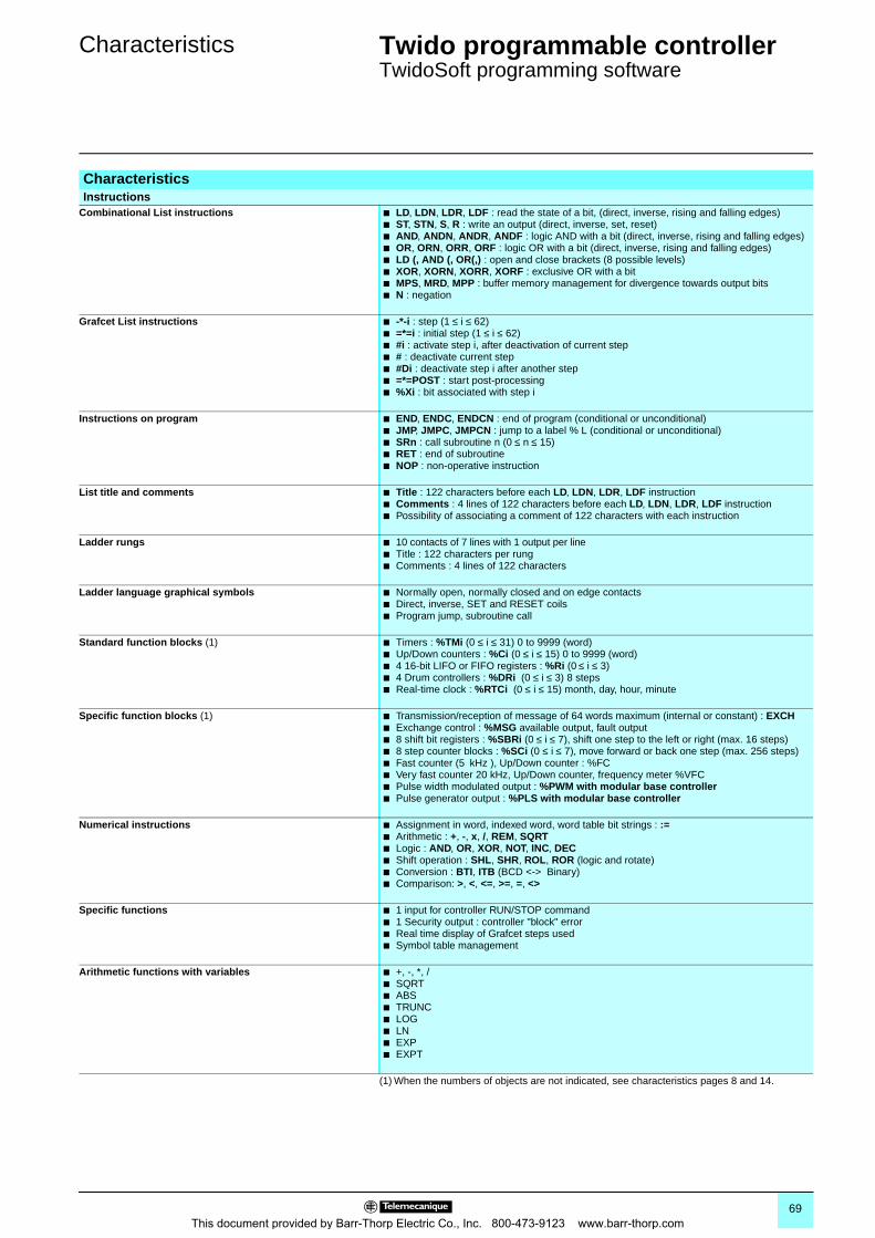
Characteristics 0 Twido programmable controller 0
TwidoSoft programming software
CharacteristicsInstructions
Combinational List instructions b LD, LDN, LDR, LDF : read the state of a bit, (direct, inverse, rising and falling edges)b ST, STN, S, R : write an output (direct, inverse, set, reset)b AND, ANDN, ANDR, ANDF : logic AND with a bit (direct, inverse, rising and falling edges)b OR, ORN, ORR, ORF : logic OR with a bit (direct, inverse, rising and falling edges)b LD (, AND (, OR(,) : open and close brackets (8 possible levels)b XOR, XORN, XORR, XORF : exclusive OR with a bitb MPS, MRD, MPP : buffer memory management for divergence towards output bitsb N : negation
Grafcet List instructions b -*-i : step (1 ≤ i ≤ 62)b =*=i : initial step (1 ≤ i ≤ 62)b #i : activate step i, after deactivation of current stepb # : deactivate current stepb #Di : deactivate step i after another stepb =*=POST : start post-processingb %Xi : bit associated with step i
Instructions on program b END, ENDC, ENDCN : end of program (conditional or unconditional)b JMP, JMPC, JMPCN : jump to a label % L (conditional or unconditional)b SRn : call subroutine n (0 ≤ n ≤ 15)b RET : end of subroutineb NOP : non-operative instruction
List title and comments b Title : 122 characters before each LD, LDN, LDR, LDF instructionb Comments : 4 lines of 122 characters before each LD, LDN, LDR, LDF instructionb Possibility of associating a comment of 122 characters with each instruction
Ladder rungs b 10 contacts of 7 lines with 1 output per lineb Title : 122 characters per rungb Comments : 4 lines of 122 characters
Ladder language graphical symbols b Normally open, normally closed and on edge contactsb Direct, inverse, SET and RESET coilsb Program jump, subroutine call
Standard function blocks (1) b Timers : %TMi (0 ≤ i ≤ 31) 0 to 9999 (word)b Up/Down counters : %Ci (0 ≤ i ≤ 15) 0 to 9999 (word)b 4 16-bit LIFO or FIFO registers : %Ri (0 ≤ i ≤ 3)b 4 Drum controllers : %DRi (0 ≤ i ≤ 3) 8 stepsb Real-time clock : %RTCi (0 ≤ i ≤ 15) month, day, hour, minute
Specific function blocks (1) b Transmission/reception of message of 64 words maximum (internal or constant) : EXCHb Exchange control : %MSG available output, fault outputb 8 shift bit registers : %SBRi (0 ≤ i ≤ 7), shift one step to the left or right (max. 16 steps)b 8 step counter blocks : %SCi (0 ≤ i ≤ 7), move forward or back one step (max. 256 steps)b Fast counter (5 kHz ), Up/Down counter : %FC b Very fast counter 20 kHz, Up/Down counter, frequency meter %VFC b Pulse width modulated output : %PWM with modular base controllerb Pulse generator output : %PLS with modular base controller
Numerical instructions b Assignment in word, indexed word, word table bit strings : :=b Arithmetic : +, -, x, /, REM, SQRTb Logic : AND, OR, XOR, NOT, INC, DECb Shift operation : SHL, SHR, ROL, ROR (logic and rotate)b Conversion : BTI, ITB (BCD <-> Binary)b Comparison: >, <, <=, >=, =, <>
Specific functions b 1 input for controller RUN/STOP commandb 1 Security output : controller "block" errorb Real time display of Grafcet steps usedb Symbol table management
Arithmetic functions with variables b +, -, *, /b SQRTb ABSb TRUNCb LOGb LNb EXPb EXPT
(1) When the numbers of objects are not indicated, see characteristics pages 8 and 14.
69This document provided by Barr-Thorp Electric Co., Inc. 800-473-9123 www.barr-thorp.com
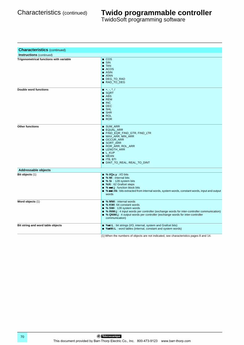
Characteristics (continued) 0 Twido programmable controller 0
TwidoSoft programming software
(1) When the numbers of objects are not indicated, see characteristics pages 8 and 14.
Characteristics (continued)
Instructions (continued) Trigonometrical functions with variable b COS
b SINb TANb ACOSb ASINb ATANb DEG_TO_RADb RAD_TO_DEG
Double word functions b +, -, *, /b SQRTb ABSb REMb INCb DECb SHLb SHRb ROLb ROR
Other functions b SUM_ARRb EQUAL_ARRb FIND_EQR_FIND_GTR, FIND_LTRb MAX_ARR, MIN_ARRb OCCUR_ARRb SORT_ARRb ROR_ARR, ROL_ARRb LENGTH_ARRb L_KUPb MEANb ITB, BTIb DINT_TO_REAL, REAL_TO_DINT
Addressable objectsBit objects (1) b % I/Qx.y : I/O bits
b % Mi : internal bitsb % Si : 128 system bitsb %Xi : 62 Grafcet stepsb % ppi.j : function block bitsb % ppi:Xk : bits extracted from internal words, system words, constant words, input and output
words
Word objects (1) b % MWi : internal wordsb % KWi: 64 constant wordsb % SWi : 128 system wordsb % INWi.j : 4 input words per controller (exchange words for inter-controller communication)b % QNWi.j : 4 output words per controller (exchange words for inter-controller
communication)
Bit string and word table objects b %pi:L : bit strings (I/O, internal, system and Grafcet bits)b %pWi:L : word tables (internal, constant and system words)
70This document provided by Barr-Thorp Electric Co., Inc. 800-473-9123 www.barr-thorp.com
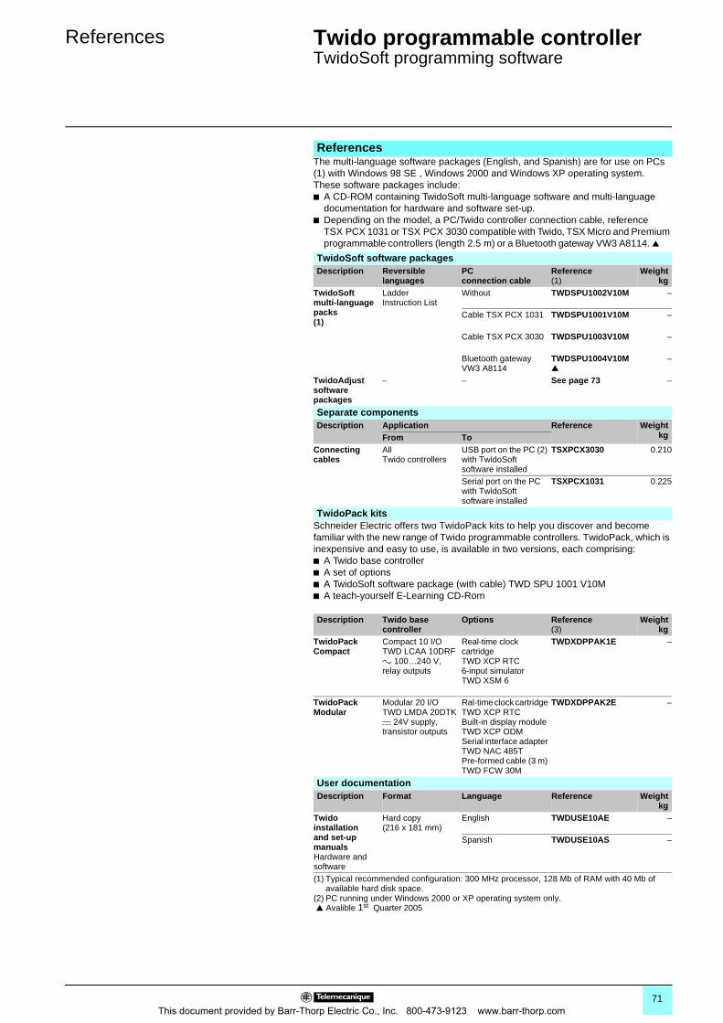
References 0 Twido programmable controller 0
TwidoSoft programming software
The multi-language software packages (English, and Spanish) are for use on PCs (1) with Windows 98 SE , Windows 2000 and Windows XP operating system.These software packages include:b A CD-ROM containing TwidoSoft multi-language software and multi-language
documentation for hardware and software set-up.b Depending on the model, a PC/Twido controller connection cable, reference
TSX PCX 1031 or TSX PCX 3030 compatible with Twido, TSX Micro and Premium programmable controllers (length 2.5 m) or a Bluetooth gateway VW3 A8114.
Schneider Electric offers two TwidoPack kits to help you discover and become familiar with the new range of Twido programmable controllers. TwidoPack, which is inexpensive and easy to use, is available in two versions, each comprising:b A Twido base controllerb A set of optionsb A TwidoSoft software package (with cable) TWD SPU 1001 V10Mb A teach-yourself E-Learning CD-Rom
References
TwidoSoft software packagesDescription Reversible
languagesPC connection cable
Reference(1)
Weightkg
TwidoSoft multi-language packs(1)
LadderInstruction List
Without TWDSPU1002V10M –
Cable TSX PCX 1031 TWDSPU1001V10M –
Cable TSX PCX 3030 TWDSPU1003V10M –
Bluetooth gatewayVW3 A8114
TWDSPU1004V10M
–
TwidoAdjust software packages
– – See page 73 –
Separate componentsDescription Application Reference Weight
kgFrom ToConnecting cables
All Twido controllers
USB port on the PC (2) with TwidoSoft software installed
TSXPCX3030 0.210
Serial port on the PC with TwidoSoft software installed
TSXPCX1031 0.225
TwidoPack kits
Description Twido base controller
Options Reference(3)
Weightkg
TwidoPack Compact
Compact 10 I/O TWD LCAA 10DRF a 100…240 V, relay outputs
Real-time clock cartridge TWD XCP RTC6-input simulator TWD XSM 6
TWDXDPPAK1E –
TwidoPack Modular
Modular 20 I/O TWD LMDA 20DTK c 24V supply, transistor outputs
Ral-time clock cartridge TWD XCP RTCBuilt-in display module TWD XCP ODMSerial interface adapter TWD NAC 485TPre-formed cable (3 m) TWD FCW 30M
TWDXDPPAK2E –
User documentationDescription Format Language Reference Weight
kgTwido installation and set-up manualsHardware and software
Hard copy(216 x 181 mm)
English TWDUSE10AE –
Spanish TWDUSE10AS –
(1) Typical recommended configuration: 300 MHz processor, 128 Mb of RAM with 40 Mb of available hard disk space.
(2) PC running under Windows 2000 or XP operating system only. Avalible 1st Quarter 2005
71This document provided by Barr-Thorp Electric Co., Inc. 800-473-9123 www.barr-thorp.com
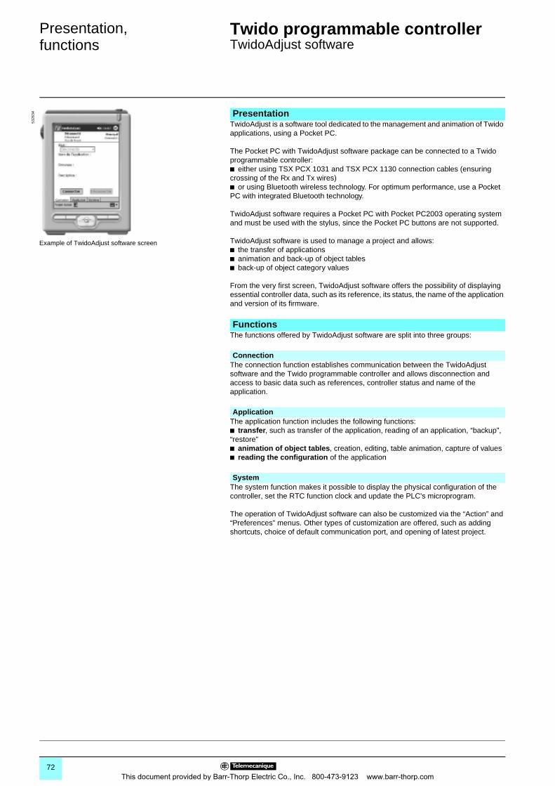
Presentation,functions 0
Twido programmable controller 0
TwidoAdjust software
TwidoAdjust is a software tool dedicated to the management and animation of Twido applications, using a Pocket PC.
The Pocket PC with TwidoAdjust software package can be connected to a Twido programmable controller: b either using TSX PCX 1031 and TSX PCX 1130 connection cables (ensuring crossing of the Rx and Tx wires)b or using Bluetooth wireless technology. For optimum performance, use a Pocket PC with integrated Bluetooth technology.
TwidoAdjust software requires a Pocket PC with Pocket PC2003 operating system and must be used with the stylus, since the Pocket PC buttons are not supported.
TwidoAdjust software is used to manage a project and allows:b the transfer of applicationsb animation and back-up of object tablesb back-up of object category values
From the very first screen, TwidoAdjust software offers the possibility of displaying essential controller data, such as its reference, its status, the name of the application and version of its firmware.
The functions offered by TwidoAdjust software are split into three groups:
The connection function establishes communication between the TwidoAdjust software and the Twido programmable controller and allows disconnection and access to basic data such as references, controller status and name of the application.
The application function includes the following functions:b transfer, such as transfer of the application, reading of an application, “backup”, “restore”b animation of object tables, creation, editing, table animation, capture of valuesb reading the configuration of the application
The system function makes it possible to display the physical configuration of the controller, set the RTC function clock and update the PLC's microprogram.
The operation of TwidoAdjust software can also be customized via the “Action” and “Preferences” menus. Other types of customization are offered, such as adding shortcuts, choice of default communication port, and opening of latest project.
Presentation
Example of TwidoAdjust software screen
5326
34
Functions
Connection
Application
System
72This document provided by Barr-Thorp Electric Co., Inc. 800-473-9123 www.barr-thorp.com
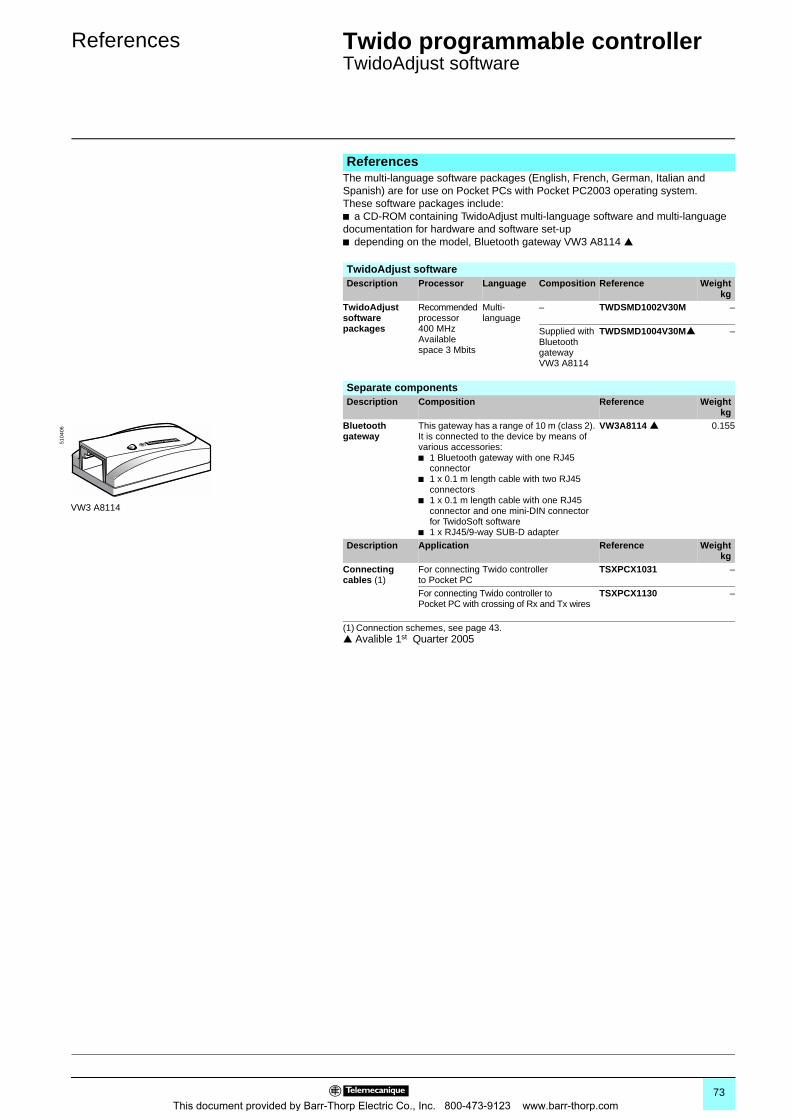
References 0 Twido programmable controller 0
TwidoAdjust software
ReferencesThe multi-language software packages (English, French, German, Italian and Spanish) are for use on Pocket PCs with Pocket PC2003 operating system.These software packages include:b a CD-ROM containing TwidoAdjust multi-language software and multi-language documentation for hardware and software set-upb depending on the model, Bluetooth gateway VW3 A8114
TwidoAdjust softwareDescription Processor Language Composition Reference Weight
kgTwidoAdjust software packages
Recommended processor 400 MHz Available space 3 Mbits
Multi-language
– TWDSMD1002V30M –
Supplied with Bluetooth gateway VW3 A8114
TWDSMD1004V30M –
Separate componentsDescription Composition Reference Weight
kgBluetooth gateway
This gateway has a range of 10 m (class 2). It is connected to the device by means of various accessories:b 1 Bluetooth gateway with one RJ45
connectorb 1 x 0.1 m length cable with two RJ45
connectorsb 1 x 0.1 m length cable with one RJ45
connector and one mini-DIN connector for TwidoSoft software
b 1 x RJ45/9-way SUB-D adapter
VW3A8114 0.155
Description Application Reference Weightkg
Connecting cables (1)
For connecting Twido controller to Pocket PC
TSXPCX1031 –
For connecting Twido controller to Pocket PC with crossing of Rx and Tx wires
TSXPCX1130 –
(1) Connection schemes, see page 43. Avalible 1st Quarter 2005
VW3 A8114
5104
06
73This document provided by Barr-Thorp Electric Co., Inc. 800-473-9123 www.barr-thorp.com
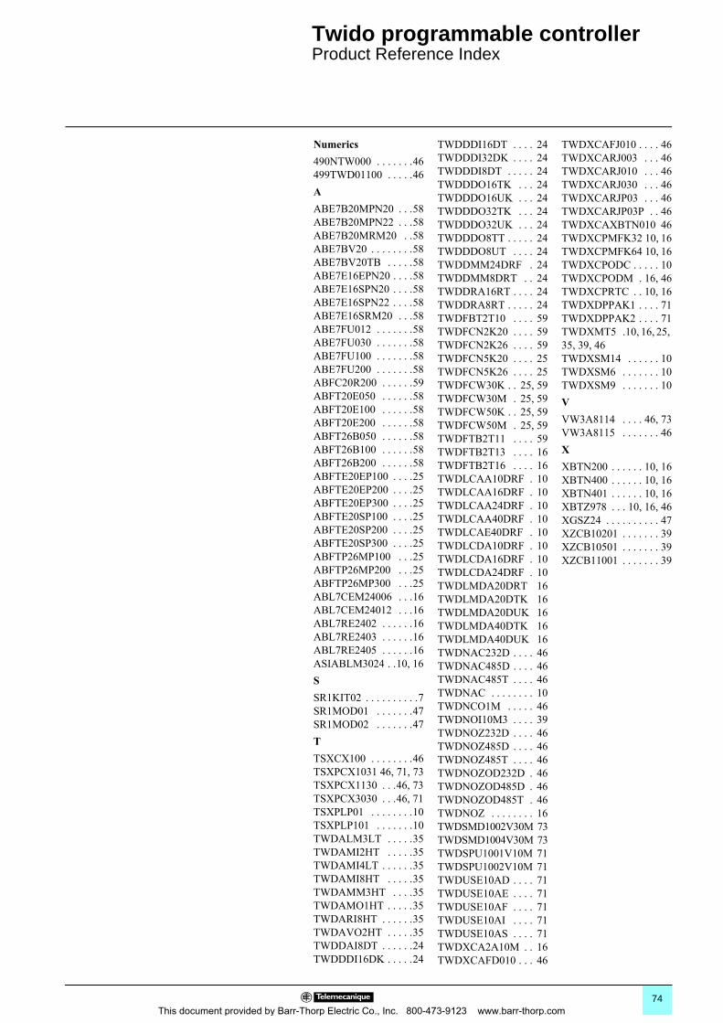
0
Twido programmable controller 0
Product Reference Index
This
document provided by Barr-TNumerics490NTW000 . . . . . . .46499TWD01100 . . . . .46AABE7B20MPN20 . . .58ABE7B20MPN22 . . .58ABE7B20MRM20 . .58ABE7BV20 . . . . . . . .58ABE7BV20TB . . . . .58ABE7E16EPN20 . . . .58ABE7E16SPN20 . . . .58ABE7E16SPN22 . . . .58ABE7E16SRM20 . . .58ABE7FU012 . . . . . . .58ABE7FU030 . . . . . . .58ABE7FU100 . . . . . . .58ABE7FU200 . . . . . . .58ABFC20R200 . . . . . .59ABFT20E050 . . . . . .58ABFT20E100 . . . . . .58ABFT20E200 . . . . . .58ABFT26B050 . . . . . .58ABFT26B100 . . . . . .58ABFT26B200 . . . . . .58ABFTE20EP100 . . . .25ABFTE20EP200 . . . .25ABFTE20EP300 . . . .25ABFTE20SP100 . . . .25ABFTE20SP200 . . . .25ABFTE20SP300 . . . .25ABFTP26MP100 . . .25ABFTP26MP200 . . .25ABFTP26MP300 . . .25ABL7CEM24006 . . .16ABL7CEM24012 . . .16ABL7RE2402 . . . . . .16ABL7RE2403 . . . . . .16ABL7RE2405 . . . . . .16ASIABLM3024 . .10, 16SSR1KIT02 . . . . . . . . . .7SR1MOD01 . . . . . . .47SR1MOD02 . . . . . . .47TTSXCX100 . . . . . . . .46TSXPCX1031 46, 71, 73TSXPCX1130 . . .46, 73TSXPCX3030 . . .46, 71TSXPLP01 . . . . . . . .10TSXPLP101 . . . . . . .10TWDALM3LT . . . . .35TWDAMI2HT . . . . .35TWDAMI4LT . . . . . .35TWDAMI8HT . . . . .35TWDAMM3HT . . . .35TWDAMO1HT . . . . .35TWDARI8HT . . . . . .35TWDAVO2HT . . . . .35TWDDAI8DT . . . . . .24TWDDDI16DK . . . . .24
horp Electric Co., Inc. 800-4
TWDDDI16DT . . . . 24TWDDDI32DK . . . . 24TWDDDI8DT . . . . . 24TWDDDO16TK . . . 24TWDDDO16UK . . . 24TWDDDO32TK . . . 24TWDDDO32UK . . . 24TWDDDO8TT . . . . . 24TWDDDO8UT . . . . 24TWDDMM24DRF . 24TWDDMM8DRT . . 24TWDDRA16RT . . . . 24TWDDRA8RT . . . . . 24TWDFBT2T10 . . . . 59TWDFCN2K20 . . . . 59TWDFCN2K26 . . . . 59TWDFCN5K20 . . . . 25TWDFCN5K26 . . . . 25TWDFCW30K . . 25, 59TWDFCW30M . 25, 59TWDFCW50K . . 25, 59TWDFCW50M . 25, 59TWDFTB2T11 . . . . 59TWDFTB2T13 . . . . 16TWDFTB2T16 . . . . 16TWDLCAA10DRF . 10TWDLCAA16DRF . 10TWDLCAA24DRF . 10TWDLCAA40DRF . 10TWDLCAE40DRF . 10TWDLCDA10DRF . 10TWDLCDA16DRF . 10TWDLCDA24DRF . 10TWDLMDA20DRT 16TWDLMDA20DTK 16TWDLMDA20DUK 16TWDLMDA40DTK 16TWDLMDA40DUK 16TWDNAC232D . . . . 46TWDNAC485D . . . . 46TWDNAC485T . . . . 46TWDNAC . . . . . . . . 10TWDNCO1M . . . . . 46TWDNOI10M3 . . . . 39TWDNOZ232D . . . . 46TWDNOZ485D . . . . 46TWDNOZ485T . . . . 46TWDNOZOD232D . 46TWDNOZOD485D . 46TWDNOZOD485T . 46TWDNOZ . . . . . . . . 16TWDSMD1002V30M 73TWDSMD1004V30M 73TWDSPU1001V10M 71TWDSPU1002V10M 71TWDUSE10AD . . . . 71TWDUSE10AE . . . . 71TWDUSE10AF . . . . 71TWDUSE10AI . . . . 71TWDUSE10AS . . . . 71TWDXCA2A10M . . 16TWDXCAFD010 . . . 46
73-9123 www.barr-thorp.c
TWDXCAFJ010 . . . . 46TWDXCARJ003 . . . 46TWDXCARJ010 . . . 46TWDXCARJ030 . . . 46TWDXCARJP03 . . . 46TWDXCARJP03P . . 46TWDXCAXBTN010 46TWDXCPMFK32 10, 16TWDXCPMFK64 10, 16TWDXCPODC . . . . . 10TWDXCPODM . 16, 46TWDXCPRTC . . 10, 16TWDXDPPAK1 . . . . 71TWDXDPPAK2 . . . . 71TWDXMT5 .10, 16, 25, 35, 39, 46TWDXSM14 . . . . . . 10TWDXSM6 . . . . . . . 10TWDXSM9 . . . . . . . 10VVW3A8114 . . . . 46, 73VW3A8115 . . . . . . . 46XXBTN200 . . . . . . 10, 16XBTN400 . . . . . . 10, 16XBTN401 . . . . . . 10, 16XBTZ978 . . . 10, 16, 46XGSZ24 . . . . . . . . . . 47XZCB10201 . . . . . . . 39XZCB10501 . . . . . . . 39XZCB11001 . . . . . . . 39
74om
Twido programmable controller 0
Community regulationsProtective treatment of equipment
Opening up of European markets assumes harmonisation of the regulations pertaining to each of the member countries of the European Union.The purpose of the European Directive is to eliminate obstacles hindering the free circulation of goods within the European Union, and it applies to each member country.Member countries are obliged to transcribe each Directive into their national legislation and to simultaneously withdraw any contradictory regulations.The Directives, in particular those of a technical nature which concern us, only establish the objectives to be achieved, referred to as "essential requirements".The manufacturer must take all the necessary measures to ensure that his products conform to the requirements of each Directive applicable to his production.As a general rule, the manufacturer certifies conformity to the essential requirements of the Directive(s) for his product by affixing the e mark.The e mark is affixed to our products concerned.
p The e mark affixed to a product signifies that the manufacturer certifies that the product conforms to the relevant European Directive(s) which concern him; this condition must be met to allow marketing and free circulation within the countries of the European Union of any product subject to one or more of the E.U. Directives.p The emark is intended solely for national market control authorities.
For electrical equipment, only conformity to standards signifies that the product is suitable for its designed function. Only the guarantee of an established manufacturer can provide a high level of quality assurance.For our products, one or several Directives are likely to be applicable, depending on the product, and in particular:p The Low Voltage Directive 72/23/EEC amended by Directive 93/68/EEC: under the terms of this Directive, e marking could not be applied before 1st January 1995 and has been compulsory since 1st January 1997.p The Electromagnetic Compatibility Directive 89/336/EEC, amended by Directives 92/31/EEC and 93/68/EEC: the e mark on products covered by this Directive has been compulsory since 1st January 1996.
Twido programmable controllers meet the requirements of “TC” treatment (1).For installations in industrial production workshops or in an environment which corresponds to “TH” treatment (2), Twido programmable controllers should be enclosed in casings with a minimum of IP 54 protection as defined by standards IEC 60950 or NEMA 250.Twido programmable controllers are supplied with an IP 20 protection index. They can therefore be installed without an enclosure in locations with restricted access which do not exceed degree of pollution 2 (control room not containing machinery or dust producing activities).
(1) “TC” treatment: all climate treatment.(2) “TH” treatment: treatment for hot and humid environments.
Community regulationsEuropean Directives
Significance of the e mark
Protective treatment of equipment
75This document provided by Barr-Thorp Electric Co., Inc. 800-473-9123 www.barr-thorp.com

DIA
3ED
2041
102E
N-U
S
Simply Smart !
The efficiency of Telemecanique branded solutionsUsed in combination, Telemecanique products provide quality solutions, meeting all your Automation & Control applications requirements.
A worldwide presence
Constantly availableb More than 5,000 points of sale in 130 countries.b You can be sure to find the range of products that are right for you and which complies fully with the standards in the country where they are used.
Technical assistance wherever you areb Our technicians are at your disposal to assist you in finding the optimum solution for your particular needs.b Schneider Electric provides you with all necessary technical assistance, throughout the world.
DIA3ED2041102EN-US © 2005 Schneider Electric All Rights Reserved
Schneider Electric USA8001 Highway 64 EastKnightdale, NC 275451-888-SquareD (1-888-778-2733)www.us.SquareD.com
Schneider Electric Canada19 Waterman Avenue,M4B 1 Y2Toronto, Ontario1-800-565-6699www.schneider-electric.ca
01/2005This document provided by Barr-Thorp Electric Co., Inc. 800-473-9123 www.barr-thorp.com