profitest prime prime ac testers for iec 60364-6, en 50110-1, iec 60204-1, iec 61439 … ·...
TRANSCRIPT

Operating Instructions
PROFITEST PRIME, PRIME ACTesters for IEC 60364-6, EN 50110-1, IEC 60204-1, IEC 61439-1, DIN EN 62446-1 and DIN EN 61851-1 3-349-933-03
5/4.19
Test Instrument for Use by Electrically Qualified Persons Only!

2 GMC-I Messtechnik GmbH
9 610 8Key1 Measuring circuit fuses2 Connector for inlet plug with country-specific mains plug3 Mains connection fuses4 Illuminated on/off switch5 RS 232 port for connecting:
– T/H sensor (Z506G) (measurement in T%rH switch position)– Barcode reader for data entry
6 Rotary selector switch (positions: off, measuring functions, charge and setup)
7 USB slave for connection to a PC (firmware update, report generation, loading test sequences created at a PC)
8 Softkeys (menu-dependent keys for selecting parameters and limit values, and for saving)
9 Display panel10 Fixed function keys (ESC, MEM, HELP, ON/START and IΔN)11 Coded probe connector sockets, each 2-pole with 4-wire
technology (probes for 1(L), 2(N) and 3(PE) as well as L1, L2 and L3). Jack socket 1(L) permits connection of an optional I-SK4 remote control unit (Z506T) with a 4 meter cable or an
I-SK12 (Z506U) with a 12 meter cable including the followingfunctions: Start-Stop / IΔN / Save-Send and measuring point illu-mination.
12 Current clamp sensor connector socket for (leakage) current measurement (PROFICLIP, Z3512A*, WZ12C*, METRAFLEX P300*) (measurement in ≤1V≅ switch position) Only the current clamp sensors offered as accessories may be connected to these sockets. * With adapter from banana plug socket to Z506J functionplug
13 Reset key: see section 26.2 on page 108 regarding use.14 LED „Electrical TEST“ lights up red: basic measuring functions
are active, use of probes 1(L), 2(N) and 3(PE) at the sockets with the same designations, lights up briefly when the sys-tem is started (function test), Attention: If the red “Electrical TEST” LED doesn’t light up during the function test, do not perform any more measurements and contact our service department (for address see section 29). But doesn’t light up when the T/F sensor (Z506G) is con-nected.
15 Bluetooth® interface (location not specified)
421
7 5
312 13
11
Connection, Control and Display Panel, PROFITEST PRIME
14

GMC-I Messtechnik GmbH 3
9 610 8Key1 Measuring circuit fuses2 Connector for inlet plug with country-specific mains plug3 Mains connection fuses4 Illuminated on/off switch5 RS 232 port for connecting:
– T/H sensor (Z506G) (measurement in T%rH switch position)– Barcode reader for data entry
6 Rotary selector switch (positions: off, measuring functions, charge and setup)
7 USB slave for connection to a PC (firmware update, report generation, loading test sequences created at a PC)
8 Softkeys (menu-dependent keys for selecting parameters and limit values, and for saving)
9 Display panel10 Fixed function keys (ESC, MEM, HELP, ON/START and IΔN)11 Coded probe connector sockets, each 2-pole with 4-wire
technology (probes for 1(L), 2(N) and 3(PE) as well as L1, L2 and L3 cannot be mixed up), jack socket 1(L) permits con-nection of an optional I-SK4 remote control unit (Z506T) with a 4 meter cable or an I-SK12 (Z506U) with a 12 meter cable including the following functions: Start-Stop / IΔN / Save-Send and measuring point illumination.
12 Coded probe connector sockets for HV (probes 1 and 2), each 2-pole with 4-wire technology for high-voltage pistols (probes for HV AC and HV DC are coded in order to rule out the connection of incorrect probes)
13 Key switch for enabling HV test voltage14 Connector socket for emergency off switch: STOP
PROFITEST PRIME AC (Z506D)15 LED „HV TEST“ lights up red: HV AC test is selected, use of
high-voltage pistols at the HV-P sockets, blinks during active measurement, lights up briefly when the system is started (function test) Attention: If the red “HV TEST” LED doesn’t light up during the function test, do not perform any more measurements and con-tact our service department (for address see section 29).
16 Connector socket for signal lamp combination: SIGNAL PROFITEST PRIME AC (Z506B)
17 Function connector socket for current clamp sensor for (leakage) current measurement (PROFICLIP, Z3512A*, WZ12C*, METRAFLEX P300*) (measurement in ≤1V≅ switch position) Only the current clamp sensors offered as accesso-ries may be connected to these sockets. * With adapter from banana plug socket to Z506J function plug
18 Reset key: see section 26.2 on page 108 regarding use.19 LED „Electrical TEST“ lights up red: basic measuring functions
are active, use of probes 1(L), 2(N) and 3(PE) at the sockets with the same designations, lights up briefly when the sys-tem is started (function test),Attention: If the red “Electrical TEST” LED doesn’t light up during the function test, do not perform any more measurements and contact our service department (for address see section 29). But doesn’t light up when the T/F sensor (Z506G) is con-nected.
20 Bluetooth® interface (location not specified)
421
7 5
317 19
12 11
151413
Connection, Control and Display Panel, PROFITEST PRIME AC16 18

4 GMC-I Messtechnik GmbH
LEDs, see section 24
MAINS NETZ LEDThe MAINS NETZ LED indicates the current status of voltage con-nected to the test probes. It lights up green, red or orange, or blinks green or red depending upon how the instrument has been connected and the selected function (see also section 24, “Functionality of the Probes, Indica-tion by Means of LEDs and LCD Symbols”, as of page 91).This LED also lights up if line voltage is present during measure-ment of RLO and RISO.
BATT LEDThe BATT LED indicates the charging status of the integrated rechargeable battery.Lights up yellow: During battery operation when lowBlinks green: – Slowly while charging
– Rapidly in the quick charge modeLights up red: Battery error
UL/RL LEDThe UL/ RL LED indicates that limit values have been exceeded or fallen short of. This LED lights up red if touch voltage is greater than 25 V or 50 V during RCD testing, as well as after safety shut-down occurs. It also lights up when RLO or RISO limit values have been exceeded or fallen short of.
RCD FI LEDThe RCD FI LED lights up red in the case of faulty tripping perfor-mance of the residual current device under test.This LED lights up red if the RCCB is not tripped within 400 ms (1000 ms for selective RCDs – type RCD S) during the tripping test with nominal residual current. It also lights up if the RCCB is not tripped before nominal residual current has been reached during measurement with rising residual current.
Keys
ESC Key Return from the submenu
MEM Key Access the memory structureThe measurement is stopped when the MEM key is pressed.
HELP Key The following information can be dis-played for each switch position and basic function after it has been selected with the rotary selector switch:Wiring diagram, measuring range, nominal range of use and mea-suring uncertainty, as well as nominal value
ON/Start Key ▼ The measuring sequence for the func-tion selected in the menu is started by pressing this key on the control panel. Exception: voltage measurement U or Ures.This key has the same function as the ▼ key on the Z506T* or Z506U* intelligent test probe.
IΔN / I Key The following sequences are triggered by pressing this key on the control panel:• Starts the tripping test after measurement of touch voltage for
RCCB testing (IΔN).• Measurement of ROFFSET is started within the RLO function.• Semiautomatic polarity reversal (see section 8.6)This key has the same function as the II key on the Z506T* or Z506U* intelligent test probe.
* Optional accessories, not included
MEM: Key for memory functions
HELP: Access context sensitive help
IΔN: Tripping testNext step (semiautomatic measurement)Start offset measurement
ON/START: Switch on Start/stop measurement
ESC: Return to submenuSoftkeys
Fixed Function Keys
• Parameter selection• Limit value specification• Entry functions• Memory functions
LEDs and connection symbols → section 24
10
• MAINS NETZ – Mains connection indicator – Interference voltage indicator for RLO and RISO
• Battery charge level
• Touch voltage limit value violation
• Lights up when RCD is tripped
8
Control and Display Panel

GMC-I Messtechnik GmbH 5
Key
Overview of Device Settings and Measuring Functions Switch Setting
Picto-graph
Device SettingsMeasuring Functions
Device SettingsOff Measuring instrument is switched off, charging function inac-
tive. The integrated rechargeable batteries are charged in all rotary switch positions.
Quick Charge
The batteries are charged and the charging monitor is displayed. Prerequisite: the charging cable is connected and the mains switch is set to on.
Setup
page 20
Test: LEDs
Test: LCD, acoustic signal, charge level / battery voltage
Bluetooth®, database mode, brightness/contrast, time/date, user language, profiles, turn-off time, default settings Firmware, calibration date, adjustment date
Enter, select, delete inspector
Battery displayMeasuring function
Meas. running / stopped Memory occupancy
Measured Parameters
Display Panel
Save value
Battery full
Battery OK
Battery weak
Battery (almost) dead
Battery display
BATT
BATT
BATT
BATT
Memory Occupancy Display
MEM Memory half full
MEM Memory full > transfer data to PC
Connection Test – Mains Connection Test (→ section 24)
N
PE
L N
PE
L)(Connection OK L and N reversed
N
PE
L N
PE
Lx
N
PE
L N
PE
L
xx
RUN READY
Connection Test (section 24)
U < 9.6 V
L
PE
Nx
L
PE
N
These operating instructions describe a tester with software version SW-VERSION (SW1) 03.03.00.
Bluetooth® active display:
quantities
Measuring FunctionsMeasurements with line voltageU
page 29
Voltage measurement – 2-poleUL-PE 2-pole voltage measurementVoltage measurement – 3-phase systemUL3-L1 Voltage between L3 and L1UL1-L2 Voltage between L1 and L2UL2-L3 Voltage between L2 and L3f Frequency
Phase sequence
Appears for all measure-ments below:
U / UN Line voltage / nominal line voltagef / fN Line frequency / nominal line frequency
RCD IFpage 44
UIΔN Touch voltageIΔ Residual currentRE Earth loop resistance
RCD IΔNpage 46
UIΔN Touch voltageta ~ Time to tripRE Earth loop resistance
RCD IF+ IΔNpage 48
UIΔN Touch voltageta ~ Time to tripIΔ Residual currentRE Earth loop resistance
ZLOOP
page 58
Z Loop / line impedance ZL-PE/ZL-NIK Short-circuit current
ZLOOP DC+page 59
Z Loop impedance ZL-PE with suppressionof tripping of type A RCD
IK Short-circuit current
ZLOOP
page 60
Z Loop / line impedance ZL-PE/ZL-N withsuppression of tripping of type B RCD
IK Short-circuit current
ZLOOP
page 61
Z Loop impedance with IΔN/2 for avoiding RCD tripping
IK Short-circuit current
Measurements at voltage-free objectsRLO 0.2A
RLO 25 Apage 31
RLO 0,2A Low-resistance measurement with200 mA and automatic polarity reversal
RLO 25A Low-resistance measurement with 25 A (IHIGH) *
ROFFSET Offset resistance for extension cords* Only possible with mains connection
RISOpage 37RISO ramppage 39
RISO Insulation resistance (constant test current)RISO rampU Voltage at the test probesUINS Test voltage
Ramp: triggering/breakdown voltageUres
page 62
Ures Undervoltage / residual voltage after discharge time tU
U Momentary voltage (supply voltage)tU Discharge time: value must drop to U ≤ Ulim
IMDpage 63
RL-PE Specify insulation resistancetA Tripping time will be calculated
RCMpage 66
UIΔN RCM (residual current monitoring)
ILpage 69
IL Residual, or leakage currentf Frequency
≤1V≅page 70
IL/AMP Residual or leakage current
T%rhpage 72
ϑ Temperature r. H. Relative humidity
EXTRA
page 73
ΔU Voltage drop measuremente-mobility Electric vehicles at charging stations (IEC 61851) PRCD Testing of type S and K PRCDs
HVpage 79
HV AC AC testing for dielectric strength (with PROFITEST PRIME AC only)
AUTOpage 84
Test sequences /automatic test sequences
Switch Setting
Picto-graph
Device SettingsMeasuring Functions

6 GMC-I Messtechnik GmbH
Table of Contents Page Page
1 Scope of Delivery ............................................................. 8
2 Applications ................................................................... 102.1 Using Cable Sets and Test Probes .............................................102.2 Application of Inside Pocket ......................................................102.3 Features Overview of Instrument Variants IZYTRONIQ ..............11
3 Safety Features and Precautions ................................... 123.1 Special Safety Precautions and Instructions
for Voltage Tests with the PROFITEST PRIME AC Test Instruments 13
3.2 Special Safety Precautions and Instructions for PROFITEST PRIME AC ...........................................................13
3.3 Explanation of Symbols .............................................................14
4 Initial Startup ................................................................. 154.1 Power Supply ............................................................................154.1.1 Switching the Instrument On/Off – Stand-By .................................154.1.2 Charging the Batteries .................................................................15
5 Connection Instructions ................................................. 165.1 Connecting the Test Instrument to Mains Power
(Auxiliary Power) .......................................................................165.1.1 Systems with Earthing Contact Outlet ............................................165.1.2 Systems with 3-Phase Power Connection .....................................165.2 Connecting Probes and Warning Devices to the Test Instrument ...175.2.1 General .......................................................................................175.2.2 Standard Test Probes ...................................................................175.2.3 Smart Test Probes I-SK... .............................................................175.2.4 High-Voltage Pistols for PROFITEST PRIME AC .............................175.2.5 Key Switch on PROFITEST PRIME AC ..........................................175.2.6 External Signal Lamps for PROFITEST PRIME AC ..........................175.2.7 Emergency Off Switch for PROFITEST PRIME AC ..........................175.2.8 Current Clamp Sensors ................................................................17
6 Indication of Operating States for the PROFITEST PRIME AC ....18
7 Device Settings – Setup ................................................. 20
8 General Notes ................................................................ 258.1 Automatic Settings, Monitoring and Shut-Off ...........................258.2 Measured Value Display and Memory .......................................258.3 Help Function ............................................................................268.4 Setting Parameters or Limit Values using RCD Measurement as an
Example .....................................................................................268.5 Freely Selectable Parameter Settings or Limit Values ..............278.5.1 Changing Existing Parameters ......................................................278.5.2 Adding New Parameters ...............................................................278.6 2-Pole Measurement with Fast or Semiautomatic
Polarity Reversal .......................................................................28
9 U – Measuring Voltage and Frequency .......................... 299.1 U ......................................................................................................299.1.1 General .......................................................................................299.1.2 Help Function ..............................................................................299.1.3 Parameters .................................................................................299.1.4 U Measurement ...........................................................................299.2 U3~ ...........................................................................................309.2.1 General .......................................................................................309.2.2 Help Function ..............................................................................309.2.3 U3~ Measurement ......................................................................309.2.4 Notes: .........................................................................................30
10 RLO – Measuring Low-Value Resistance ............................ 3110.1 RLO 0.2A – Measuring Low-Value Resistance with 0.2 A Test Cur-
rent ............................................................................................3110.1.1 General .......................................................................................3110.1.2 Help Function ..............................................................................3110.1.3 Parameters .................................................................................3110.1.4 ROFFSET Measurement .................................................................3210.1.5 RLO 0.2 A Measurement ..............................................................3310.1.6 Evaluation of Measured Values .....................................................3310.1.7 RLO 0.2A Measurement at PRCDs ................................................3410.2 RLO 25A – Measuring Low-Value Resistance with 25 A Test Current ..3510.2.1 Measurement Principle ................................................................3510.2.2 Help Function ..............................................................................3510.2.3 Parameters .................................................................................3510.2.4 ROFFSET Measurement .................................................................3510.2.5 RLO 25A Measurement ................................................................3610.2.6 Evaluation of Measured Values .....................................................36
11 RISO – Measurement of Insulation Resistance ................... 3711.1 Insulation Measurement with Constant Test Voltage ...............3711.1.1 General .......................................................................................3711.1.2 Help Function ..............................................................................3711.1.3 Parameters .................................................................................3711.1.4 RISO Measurement .......................................................................3811.2 RISO Ramp – Insulation Measurement with Rising Test Voltage ... 3911.2.1 General .......................................................................................3911.2.2 Help Function ..............................................................................3911.2.3 Parameters .................................................................................3911.2.4 RISO Ramp Measurement ............................................................4011.2.5 Notes on Measurement with the Ramp Function ............................4111.3 Evaluation of Measured Values .................................................41
12 RCD – Testing of Residual Current Devices ........................ 4212.1 General ......................................................................................4212.2 Measurement of Touch Voltage and Time to Trip with Nominal Re-
sidual Current ............................................................................4212.2.1 General .......................................................................................4212.2.2 Help Function ..............................................................................4212.2.3 Parameters .................................................................................4212.2.4 RCD IΔN – Measurement of Time to Trip with
Nominal Current ..........................................................................4312.3 RCD IF – Testing Residual Current Devices by
Measuring Tripping Current with Rising Test Current ...............4412.3.1 General .......................................................................................4412.3.2 Help Function ..............................................................................4412.3.3 Parameters .................................................................................4412.3.4 RCD IF Measurement ..................................................................4512.4 RCD IΔN – Testing RCDs by Measuring Time to Trip with Constant
Test Current ..............................................................................4612.4.1 General .......................................................................................4612.4.2 Help Function ..............................................................................4612.4.3 Parameters .................................................................................4612.4.4 RCD IΔN Measurement ................................................................4712.5 RCD IF + IΔN – Testing RCDs by Simultaneously Measuring Trip-
ping Current and Time to Trip with Rising Test Current ............4812.5.1 General .......................................................................................4812.5.2 Help Function ..............................................................................4812.5.3 Parameters .................................................................................4812.5.4 RCD IF + IΔN Measurement .........................................................49

GMC-I Messtechnik GmbH 7
12.6 Special Tests for Systems and RCDs ..............................................5012.6.1 Testing Systems and RCCBs with Rising Residual
Current (AC) for Type B/B+ and EV/MI RCDs .......................................5012.6.2 Testing RCCBS with 5 • IΔN ............................................................. 5012.6.3 Testing of RCCBs which are Suited for Pulsating
DC Residual Current .................................................................... 5112.6.4 Systems with Type RCD-S Selective RCCBs .................................. 5112.6.5 PRCDs with Non-Linear Type PRCD-K Elements ............................ 5212.6.6 SRCD, PRCD-S (SCHUKOMAT, SIDOS
or comparable) ............................................................................ 5312.6.7 Type G or R RCCB ....................................................................... 5312.6.8 Testing Residual Current Circuit Breakers in
TN-S Systems ............................................................................. 5412.7 Notes Concerning Measurement .............................................. 5512.7.1 General ...................................................................................... 5512.7.2 RCDs of Special Design ............................................................... 5512.7.3 Presettings ................................................................................. 55
13 Zloop – Testing of Breaking Requirements for Overcurrent Protective Devices, Measurement of Line or Loop Impedan-ce and Determination of Short-Circuit Current ............... 56
13.1 General ..................................................................................... 5613.1.1 Measurements with Suppression of RCD Tripping ......................... 5613.1.2 Settings for Calculating Short-Circuit Current
– Parameter IK .......................................................................... 5713.1.3 Special Case: Measurement without Limit Values .......................... 5713.1.4 Evaluation of Measured Values ..................................................... 5713.1.5 Accessing the Table of “Allowable Fuses” ..................................... 5713.2 Zloop AC/DC – Measuring Line/Loop Impedance ..................... 5813.2.1 Help Function .............................................................................. 5813.2.2 Parameters ................................................................................. 5813.2.3 ZLOOP AC/DC Measurement ......................................................... 5813.2.4 Notes ......................................................................................... 5813.3 Zloop DC+ – Measuring Line Impedance .................................. 5913.3.1 General ...................................................................................... 5913.3.2 Parameters ................................................................................. 5913.3.3 ZLOOP DC+ Measurement ............................................................ 5913.3.4 Notes ......................................................................................... 5913.4 Zloop – Measuring Loop Impedance ........................................ 6013.4.1 General ...................................................................................... 6013.4.2 Help Function .............................................................................. 6013.4.3 Parameters ................................................................................ 6013.4.4 ZLOOP Measurement ................................................................... 6013.4.5 Notes ......................................................................................... 6013.5 Zloop – Measuring Loop Impedance ........................................ 6113.5.1 General ...................................................................................... 6113.5.2 Help Function .............................................................................. 6113.5.3 Parameters ................................................................................ 6113.5.4 ZLOOP Measurement ................................................................... 6113.5.5 Notes ......................................................................................... 61
14 Ures – Residual Voltage Measurement .................................... 6214.1 General ..................................................................................... 6214.2 Help Function ............................................................................ 6214.3 Parameters ............................................................................... 6214.4 Ures Measurement ................................................................... 62
15 IMDs – Testing Insulation Monitoring Devices .....................6315.1 General ..................................................................................... 6315.2 Help Function ............................................................................ 6315.3 Parameters ............................................................................... 6315.4 IMD Measurement .................................................................... 6415.5 Evaluation ................................................................................. 6515.6 Retrieving Saved Measured Values .......................................... 65
16 RCM – Testing of Residual Current Monitoring Devices ................. 6616.1 General ..................................................................................... 6616.2 Help Function ............................................................................ 6616.3 Parameters ............................................................................... 6616.4 RCM Measurement ................................................................... 67
16.5 Notes Concerning Measurement .............................................. 68
17 IL – Leakage Current ......................................................6917.1 General ..................................................................................... 6917.2 Help Function ............................................................................ 6917.3 Parameters ............................................................................... 6917.4 IL Measurement ........................................................................ 69
18 IL/AMP – Current Measurement with Current Clamp Sensor ..... 7018.1 General ..................................................................................... 7018.2 Help Function ............................................................................ 7018.3 Parameters ............................................................................... 7018.4 IL/AMP Measurement ................................................................. 71
19 T %r.H. – Measurement of Temperature and Atmospheric Humidity .........................................................................72
19.1 General ..................................................................................... 7219.2 Help Function ............................................................................ 7219.3 Parameters ............................................................................... 7219.4 T % r.h. Measurement .............................................................. 72
20 Extra – Special Functions ...............................................7320.1 ΔU – Voltage Drop Measurement ............................................. 7420.1.1 General ...................................................................................... 7420.1.2 Help Function ............................................................................. 7420.1.3 Parameters ................................................................................. 7420.1.4 ZOFFSET Measurement ............................................................... 7520.1.5 ΔU Measurement ........................................................................ 7520.2 E-Mobility – Checking the Operating States of an
Electric Vehicle at Charging Stations per IEC 61851 ................ 7620.3 PRCD – Test Sequences for Documenting Fault Simulations at PRCDs
with the PROFITEST PRCD Adapter ...................................................7720.3.1 Selecting the PRCD to be Tested .................................................. 7720.3.2 Parameter Settings ..................................................................... 7720.3.3 PRCD-S Test Sequence (single-phase) – 11 Test Steps ................ 7820.3.4 PRCD-S Test Sequence (3-phase) – 18 Test Steps ....................... 78
21 HV AC – Testing for Dielectric Strength (with PROFITEST PRIME AC) ...........................................79
21.1 General ..................................................................................... 7921.1.1 Help Function ............................................................................. 7921.2 Connection ................................................................................ 7921.3 Parameters ............................................................................... 8021.4 Function Test (test preparation) ............................................... 8121.5 Test Sequence .......................................................................... 8221.5.1 Ending the Test for Dielectric Strength .......................................... 8321.5.2 Setting Ranges for Parameters and Standard Values per DIN VDE .. 83
22 AUTO – Test Sequences (automatic test sequences) ......... 8422.1 General ..................................................................................... 8422.2 Creating and Transferring Test Sequences with
IZYTRONIQ (step-by-step instructions) ..................................... 84
23 Database .........................................................................8623.1 Creating Distributor Structures, General .................................. 8623.2 Transferring Distributor Structures .......................................... 8623.3 Creating a Distributor Structure in the Test Instrument ........... 8623.3.1 Creating Structures (example for electrical circuit) ......................... 8823.3.2 Searching for Structure Elements ................................................. 8923.4 Saving Data and Generating Reports ........................................ 8923.4.1 Use of Barcode Readers .............................................................. 90
24 Functionality of the Probes, Indication by Means of LEDs and LCD Symbols ............................................................91
25 Characteristic Values ....................................................102

8 GMC-I Messtechnik GmbH
26 Maintenance and Recalibration ................................... 10826.1 Firmware Revision and Calibration Information ......................10826.2 Reset Key ................................................................................10826.3 Rechargeable Battery Operation and Charging .......................10826.4 Fuses .......................................................................................10826.4.1 Mains Connection Fuses ............................................................10826.4.2 Measuring Circuit Fuses .............................................................10826.5 Housing and Test Probes ........................................................10926.6 Measurement Cables ..............................................................10926.7 Test Leads for the High-Voltage Pistols ............................................. 10926.8 Replacing the Bulbs in the Signal Lamp Combination (Z506B) with
the PROFITEST PRIME AC ........................................................10926.9 Temperature/Humidity Sensor with Magnetic Retainer (optional) ..... 10926.10 Recalibration ...........................................................................10926.11 Software ..................................................................................109
27 Appendix ...................................................................... 11027.1 Tables for Determining Maximum and Minimum Display Values in
Consideration of Maximum Measuring Uncertainty ................11027.1.1 RLO Display Values .....................................................................11027.1.2 RISO Display Values ....................................................................11127.1.3 RCD Display Values ...................................................................11227.1.4 ZLOOP Display Values .................................................................11427.1.5 Ures Display Values ...................................................................11527.1.6 RCM Display Values ...................................................................11527.1.7 HV (PROFITEST PRIME AC) Display Values .................................11627.2 At which values should/must an RCD actually be tripped? Requi-
rements for Residual Current Devices (RCD) ...........................11727.3 Testing Electrical Machines per DIN EN 60204 –
Applications, Limit Values .......................................................11827.4 Periodic Testing per DGUV Regulation 3/4
(previously BGV A3, VBG4, UVV) – Limit Values for Electrical Systems and Operating
Equipment ............................................................................11927.5 List of Abbreviations and their Meanings
in the Order They Appear on the Rotary Switch ......................12027.6 Keyword Index .........................................................................12127.7 Bibliography ............................................................................12227.7.1 Internet Addresses for Additional Information ..............................122
28 Return and Environmentally Sound Disposal ............... 123
29 Repair and Replacement Parts ServiceCalibration Center and Rental Instrument Service ......................................................................... 124
30 Product Support ........................................................... 124
1 Scope of Delivery
1 Test instrument1 Mains power cable, 1.5 m1 Probe with 4-wire measuring technology for connection
to L conductor *1 Probe with 4-wire measuring technology for connection
to N conductor *1 Probe with 4-wire measuring technology for connection
to PE conductor *1 USB interface cable1 DAkkS calibration certificate1 Supplementary sheet with safety information1 Condensed operating instructions**
**Comprehensive operating instructions available on the Internet for download at www.gossenmetrawatt.com
1 Card with registration key for the software
* Measuring category with safety cap attached: 300 V CAT IV, 600 V CAT III, 1 A Measuring category without safety cap attached: 600 V CAT II16 A

GMC-I Messtechnik GmbH 9

10 GMC-I Messtechnik GmbH
2 Applications
This test instrument fulfills all requirements of applicable EU direc-tives and national regulations. We confirm this with the CE mark. The relevant declaration of conformity can be obtained from GMC-I Messtechnik GmbH.
PROFITEST PRIME measuring and test instruments are used for rapid and efficient testing of protective measures in accordance with DIN VDE 0100-600 (Erection of low-voltage installations; tests – initial tests), ÖVE-EN 1 (Austria), NIV/NIN SEV 1000 (Switzerland) and other country-specific regulations. The test instrument is equipped with a microprocessor and com-plies with requirements set forth in IEC 61557/EN 61557/VDE 0413:Part 1: General requirementsPart 2: Insulation resistancePart 3: Loop resistancePart 4: Resistance of earth connection and equipotential bondingPart 6: Effectiveness of residual current devices (RCDs) in TT, TN
and IT systemsPart 7: Phase sequencePart 10:Electrical safety in low-voltage systems up to 1000 V AC
and 1500 V DC – Equipment for testing, measuring or monitoring of protective measures
Part 11:Effectiveness of residual current monitors (RCMs) type A and type B in TT, TN and IT systems
Part 14:Equipment for testing the safety of electrical equipment of machinery
The test instrument is especially well suited for:• System setup• Initial startup• Periodic testing• Troubleshooting in electrical systemsAll of the values required for approval reports (e.g. per ZVEH) can be measured with this test instrument. All acquired data can be archived, and measurement and test reports can be printed out at a PC.This is of special significance where product liability is concerned.The applications range of the test instruments covers all alternat-ing and 3-phase current systems with nominal voltages of 120 V / 230 V / 400 V up to 690 V and nominal frequencies of DC, 16,7 / 50 / 60 / 200 / 400 Hz.The following can be measured and tested with the test instru-ments:• Voltage / frequency / phase sequence• Loop impedance / line impedance• Residual current devices (RCDs/PRCDs)• Insulation monitoring devices (IMDs)• Residual current monitoring devices (RCMs)• Insulation resistance• Low-value resistance (potential equalization)• Leakage current with current transformer clamp• Residual voltage• Voltage drop• Leakage / differential / touch current
The PROFITEST PRIME test instrument is intended for quick and safe testing of electrical and electronic equipment and systems in machines.According to the regulations, the following initial and periodic tests must be performed:• Testing for electrical continuity of the protective conductor sys-
tem• Insulation resistance tests• Testing for dielectric strength (PROFITEST PRIME AC)• Testing for residual voltage
The following tests can also be conducted which supplement the test instrument in a practical manner although they’re not manda-tory for verifying the electrical safety of equipment in machines:• Leakage current testing for substantiating the absence of volt-
age• Voltage and frequency measurements
All of the values required for approval reports can be measured with this instrument.All measured data can be archived using the measurement and test report which can be printed out at a PC. This is very import-ant, especially due to product reliability.
2.1 Using Cable Sets and Test Probes• Scope of delivery:
4-wire probes for 1(L), 2(N) and 3(PE) conductor connection
Measurements per DIN EN 61010-031 may only be performed in environments in accordance with measuring categories III and IV with the safety cap attached to the test probe at the end of the measurement cable.In order to establish contact inside 4 mm jacks, the safety caps have to be removed by prying open the snap fastener with a pointed object (e.g. the other test probe).
2.2 Application of Inside Pocket
Attention!!The pocket at the inside cover of the case of thePROFITEST PRIME is not intended for use as an accessorypouch. This may cause considerable damage to the front glass panel of the display.Please use the accessory pouch or the accessory casefor storing accessories.
Maximum rated voltage 300 V 600 V 600 VMeasuring category CAT IV CAT III CAT IIMaximum rated current 1 A 1 A 16 A *With safety cap attached • • —
Without safety cap or with attached alligator clip — — •

GMC-I Messtechnik GmbH 11
2.3 Features Overview of Instrument Variants IZYTRONIQ
X: included0: available as option—: not available
PROFITEST...(article number)
PRIM
E(M
506A
)PR
IME
AC(M
506C
)
Voltage and Frequency Measurement up to 1 kVIn single-phase AC/DC systems X XIn 3-phase systems (UL1-L3, UL1-L2, UL2-L3) X XPhase sequence testing X XMeasurement of Protective Conductor Resistance RLOWith 0.2 A measuring current: constant/ramp, polarity and test time can be selected X X
With 25 A measuring current X XMeasurement of Insulation Resistance RISOWith constant DC test voltage (50 …1000 V) X XWith DC ramp function X XTesting of Residual Current DevicesGeneral and selective including RCD, SRCD, PRCD, G/R and RCBO (FI-LS) variants X X
Testing of AC/DC sensitive RCDs, types B, B+ and EV X XMeasurement of fault voltage without tripping the RCD X XTripping current measurement with ramp function X XMeasurement of time to trip X XSimultaneous measurement of tripping current and time to trip with “intelligent ramp” X X
Loop Impedance MeasurementMeasurement with full-wave, test current: 10 A AC/DC X XMeasurement in 690 V systems X XMeasurement in DC systems X XWithout tripping the RCD (type AC, A) by means of “DC saturation process” X X
Combined process without tripping the RCD: “impedance Z + R” X XWithout tripping the RCD: 15 mA process X XDisplay of permissible fuse types in a table X XResidual Voltage Test X XTesting of Insulation Monitoring Devices (IMDs) X XTesting of Residual Current Monitoring Devices (RCMs) X XLeakage Current Measurement (direct) X XCurrent Measurement (with optional current clamp sensor) X XMeasurement of Temperature and Atmospheric Humidity X XVoltage Drop Measurement ΔU X XDocumentation of Charging Station Tests X XDocumentation of Fault Simulations at PRCDs with the Profitest|PRCD Adapter X X
HV AC Dielectric Strength Test, 2.5 kV / 200 mA — Xwith constant AC test voltage — XBreakdown voltage measurement with ramp function — XPulse control mode for troubleshooting — XFeaturesAutomatic test sequence function X XSelectable menu language: D, GB, F, NL, I, E, CZ, NO X XPush-print function (storage or transmission via Bluetooth) X XDatabase (max. 30,000 objects can be saved) X XOperation via optional control probe: (Start/IΔN/Save/Light) O ORS 232 port for RFID/barcode reader X XInterface for data transmission via Bluetooth® X XInterface for data transmission via USB X XReport generating program IZYTRONIQ X XMeasuring category for basic measuring functions: 600 V CAT III / 300 V CAT IV X X
HV AC terminals: 2.5 kV / 200 mA — XHV DC terminals:5 kV — —DAkkS calibration certificate X X

12 GMC-I Messtechnik GmbH
3 Safety Features and Precautions
The electronic measuring and test instrument is manufactured and tested in accordance with safety regulations IEC 61010-1/DIN EN 61010-1/VDE 0411-1.Safety of the operator, as well as that of the instrument, is only assured when it’s used for its intended purpose.
Read the operating instructions thoroughly and carefully before using your instrument. Follow all instructions contained therein. Make sure that the operating instructions are available to all users of the instru-ment.
Tests may only be executed by a qualified electrician.
The measuring and test instrument may not be placed into ser-vice:• If external damage is apparent• If connector cables or measuring adapters are damaged• If the instrument no longer functions flawlessly• After long periods of storage under unfavorable conditions
(e.g. humidity, dust or extreme temperature• If the red “Electrical TEST”* or “HV TEST”* LED doesn’t light up
during the function test, do not perform any more measure-ments and contact our service department (for address seesection 29).
• If any modifications have been applied to the test and measu-ring instrument itself and/or to its accessories.
* PROFITEST PRIME: Operating Instructions page 2 Key item no. 14 PROFITEST PRIME AC: Operating Instructions page 3 Key item no. 15 or 19
Exclusion of LiabilityWhen testing systems with RCCBs, they may switch off. This may occur even though the test does not normally provide for it. Leak-age currents may be present which, in combination with the test current of the test instrument, exceed the shutdown threshold value of the RCCB. PCs which are operated in proximity to such RCCB systems may switch off as a consequence. This may result in inadvertent loss of data. Before conducting the test, precau-tions should therefore be taken to ensure that all data and pro-grams are adequately saved, and the computer should be switched off if necessary. The manufacturer of the test instrument assumes no liability for any direct or indirect damage to equip-ment, computers, peripheral equipment or databases when per-forming the tests.HV-AC: The manufacturer explicitly excludes any liability in the event of misuse, the use of improper or altered accessories or in the event of manipulation of the test and measuring instrument or its accessories.
Opening the Instrument / RepairsThe instrument may only be opened by authorized, trained per-sonnel in order to ensure flawless operation and to assure that the guarantee is not rendered null and void.Even original replacement parts may only be installed by autho-rized, trained personnel.If it can be ascertained that the instrument has been opened by unauthorized personnel, no guarantee claims can be honored by the manufacturer with regard to personal safety, measuring accu-racy, compliance with applicable safety measures or any conse-quential damages.If the guarantee seal is damaged or removed, all guarantee claims are rendered null and void.
Meanings of Symbols on the InstrumentWarning concerning a point of danger (attention, observe documentation!)
Protection category I device
Protection category II device
This device may not be disposed of with the trash. Fur-ther information regarding the WEEE mark can be accessed on the Internet at www.gossenme-trawatt.com by entering the search term “WEEE”.CE Conformity Marking
By removing the TORX Screw on the right side of the measuring circuit fuses, which is fitted with blue seal-ing wax, any warranty claims are forfeited.
The special technical knowledge of qualified personnel is required for electrical installation or repair.
Calibration seal (blue seal):
see also “Product Support” on page 124
Data BackupWe advise you to regularly transfer your stored data to a PC in order to prevent potential loss of data in the test instrument.We assume no responsibility for any data loss.
Precautions for TransportBefore closing the cover of the test case, please disconnect all mains cables, measurement and signal cables from the front panel terminals of the test instrument and store them separately in order to prevent them from being jammed and damaged in the process and in order to prevent scratching of the display
Safety Precautions, Rechargeable Lithium-Ion BatteryThe test instrument is powered by a rechargeable lithium-ion bat-tery. Consequently, it’s absolutely essential to observe the follow-ing points:• Temperature ranges: The test instrument must not be exposed
to direct sunlight or charged, operated or stored at high tem-peratures, for example in a car.– Charging mode (10 ... 45 °C): The battery may only be charged
within this temperature range.– Measuring mode (-5 ... 50 °C): The battery may only be used
within this temperature range. The battery is switched to theprotective mode as of 55 °C. In this case the test instrumentcan no longer be operated with the battery.
– Storage (-20 ... 60 °C): The maximum storage temperature is60 °C.
– Safety circuit: At temperatures of above 75 °C, the recharge-able battery is shut down entirely for safety reasons andmust be replaced by our service department.
• Excessive depletion: The rechargeable battery’s safety circuitconsumes minimal amounts of current. In order to prevent thebattery from becoming fully depleted, the instrument shouldbe connected to the mains for recharging at least once a year,and preferably at more frequent, regular intervals. In somecases it’s no longer possible to recharge a fully depleted bat-tery, in which case it must be replaced by our service depart-ment.
• Battery replacement: The battery cannot be replaced by the cus-tomer for reasons involving safety, transport and environmen-tal protection. If the rechargeable battery inside the instrumentis defective, it must be replaced by GMC-I Service GmbH.
!
Consecutive number
Registration numberDate of calibration (year – month)
Deutsche Akkreditierungsstelle GmbH – calibration lab XY123
2018-04
D-K15080-01-01

GMC-I Messtechnik GmbH 13
3.1 Special Safety Precautions and Instructions for Voltage Tests with the PROFITEST PRIME AC Test Instruments
Attention!!The test instrument itself must not be used as a deviceunder test for voltage testing by means of HV AC!
Checklist for High-Voltage Tests (PROFITEST PRIME AC)
Attention!!Measurements may not be performed under moist ambi-ent conditions, where condensation has occurred or in explosive atmospheres.
Personal Safety➭ Turn the machine under test off and secure against restart.➭ Perform protective conductor and insulation resistance mea-
surements.➭ Make sure that the system is grounded.➭ Secure the danger zone with barriers, closing even narrow
passageways (optional accessory:CLAIM PROFITEST PRIME AC – Z504G).
➭ Set up warning signs such that they are plainly visible.➭ Set up warning lamps such that they are plainly visible
(PROFITEST PRIME AC)➭ Attach the emergency stop switch in a plainly visible and eas-
ily accessible fashion (PROFITEST PRIME AC).➭ Warn personnel working in the area of possible danger.➭ Always turn the high-voltage module of the test instrument off
with the key switch and remove the key before leaving thework area (PROFITEST PRIME AC).
➭ the two high-voltage pistols can be operated by the inspectorwith one hand each (two-hand operation)
Safety Precautions for the Machine Under Test (recommended)➭ Review the circuit diagrams and make a note of all electrical
circuits.➭ The machine must be switched off in any case – supply power
to the machine must be disconnected and secured againstreactivation!
➭ Disconnect the neutral conductor (if included) from the mains.➭ Short circuit each electrical circuit to itself.➭ Disconnect control circuits with overvoltage arresters, if the
arresters would be triggered by the utilized test voltage.➭ Disconnect PELV circuits (no HV testing is required for these
circuits).➭ Test insulation at each circuit with 1000 V.
(If insulation resistance is OK at 1000 V, no failures shouldoccur when testing dielectric strength.)
➭ Disconnect inverters.➭ Caution in TN systems!
The protective conductor is connected to the neutral conduc-tor in this case and high-voltage is thus applied betweenphase conductor and neutral conductor. The neutral conduc-tor (if included) must be interrupted if necessary, because it’snot disconnected from the mains by means of fuses.
Setting Up the Test Instrument
Testing for Dielectric Strength➭ Test all circuits (conductors) against the protective conductor
(all switches in the mains circuit must be turned on, and test-ing must be performed upstream and downstream from all re-lays and contactors).
➭ Remove all shorting devices after testing has been completed.
Testing Without Short-Circuiting➭ Test all conductors from all circuits separately against the protective
conductor (the machine could be damaged in the case of arc-over).
Function Test➭ The machines must be tested for correct functioning after testing
for dielectric strength, especially with regard to safety functions.
3.2 Special Safety Precautions and Instructions for PROFITEST PRIME AC
Precaution for the Prevention of Unauthorized Startup• Key switch on the HV TEST connector panel
Precautions for the Prevention of Inadvertent Startup• Multiple key operation:
Before test voltage can be applied to the test probes by acti-vating the triggers at the high-voltage pistols, the ON/START keymust be pressed at the test instrument.
• High-voltage pistols with double safety feature (two-hand operation):If the triggers at the high-voltage pistols are pulled to the firstpoint of mechanical resistance, the test probes are exposed.High-voltage is not applied to the test probes until the triggersare pulled beyond this point, assuming the device is ready foractivation.
General Safety Precautions• External signal lamps indicate the switching status of the test in-
strument.• The test probes are electrically isolated from the supply mains.
This prevents current from flowing from the high-voltage pistolsto earth.
• Current limiting in the event of arc-over:If the current limit value entered as a device parameter is ex-ceeded due to arc-over, switching to the “standby” modetakes place automatically.
• When mains voltage is restored after a power failure, switching tothe “standby” mode takes place automatically.
Attention!!Observe the stipulations set forth in DIN EN 50191/VDE 0104, “Erection and operation of electrical testequipment”.
Attention!!If safety test probes are used, the operator must inspectthem to assure that the test probes and their cables arein flawless condition before placing them into service.Before use, all equipment must be inspected for visible,external damage and checked as to whether it is in pris-tine condition and free from manipulations of any kind(see section 26.5 on page 109 through section 26.7 onpage 109).
Attention!!Be sure to fully extend the measurement cables beforetesting for dielectric strength.
Attention!!Before initializing any tests, and before enabling the testequipment, make sure that all means of access to thedanger zone are closed, and that all persons have exitedthe danger zone.

14 GMC-I Messtechnik GmbH
Caution: High-Voltage!When the triggers at the high-voltage pistols are pulled to the first point of discernible mechanical resistance, the test probes are exposed. If the triggers are pulled beyond this point of mechanical resistance, high-voltage is applied to the test probes, as-suming the high-voltage module is “ready for activation” (red signal lamp illuminated).
Caution: High-Voltage!Touch neither the test probes nor the device under test during the test for dielectric strength! Life endangering high voltage of up to 2.5 kV (PROFITEST PRIME AC) is present at the test probes of the high-voltage pistols!
Attention!!No condensation may occur at the test instrument, thetest cables or the device under test, because high-volt-age may otherwise cause leakage current at the sur-faces. Insulated components may also conduct high-voltage in this case.
Exclusion of LiabilityPCs located in proximity to the test equipment may “crash” in the event of arc-over, resulting in possible data loss. Before testing for dielectric strength, precautions should therefore be taken to ensure that all data and programs are adequately saved, and the computer should be switched off if necessary. PCs may crash even if no USB connection has been established.The manufacturer of the test instrument assumes no liability for direct or consequential damages to computers, peripheral devices or data loss during testing for dielectric strength.Furthermore, the manufacturer assumes no liability for defects at devices under test resulting from testing for dielectric strength. This applies in particular to electronic components included in the device under test.For voltage tests with high-voltage, two-hand operation by the inspector is a mandatory requirement.The manufacturer is not liable for any damage caused by improper operation.Moreover, the manufacturer is not liable for damage of any kind which has been caused by the use of accessories not authorized by GMC-I and/or manipulated accessories.
Observe the checklist for voltage tests on page 13.
3.3 Explanation of Symbols
Symbols in the Operating Instructions
Life endangering for the operator if instructions identified with this symbol are not observed
Danger for the operator and the device if instruc-tions identified with this symbol are not observed
Symbols in the User Interface for High-Voltage MeasurementThe high-voltage module is ready to for activation. The high-voltage pistols can be activated.
Life endangering high voltage of up to 2.5 kV is present at the test probes.
!

GMC-I Messtechnik GmbH 15
4 Initial Startup
4.1 Power SupplyMeasuring mode operation is possible with either of two different sources of electrical power, which are however restricted depending on auxiliary power or the application: Mains operation or operation with the integrated rechargeable battery.
✔ Function available✘ Function not possible or not sensible
1 Functions for RCD type B, B+ and loop with DC disabling (Loop+DC)2 Performance of ZLOOP DC+ (DC-H), RCD IF and RCD IΔN mea-
surements with DC test current is only recommended with a battery charge level of ≥ 50%.
4.1.1 Switching the Instrument On/Off – Stand-By➭ Connect the test instrument to mains power via the inlet plug
(see section 5.1 on page 16).➭ Set the mains switch to ON “1” – the red lamp
lights up.➭ Set the rotary selector switch to U or any other
position except for OFF.The menu which corresponds to the rotary selector switch is dis-played.➭ The instrument can be switched off manually by setting the
rotary selector switch to the OFF position.➭ The instrument is disconnected from the mains by setting the
red line disconnector to OFF “0”.
Standby Function➭ The instrument is switched to the standby status for all mea-
suring functions except for continuous measurement after theshutdown time specified in SETUP (see section 7). The displayis turned off in this case.
➭ There are two ways to switch the instrument back on again:– By pressing the ON/START key at the test instrument
or– By turning the rotary selector switch to the OFF position and
then reselecting the measuring function.
Operation Without Mains PowerPrerequisites:– The batteries are charged– The mains switch is set to OFF “0”.
4.1.2 Charging the Batteries
Attention!!The internal batteries are charged inside the instrument andcannot be replaced by the user.
The batteries are continuously charged as long as the test instru-ment is connected to the mains when the mains switch is set to ON “1”, regardless of the selector switch position.
Quick Charging➭ Connect the test instrument to mains power via the inlet plug
(see section 5.1 on page 16).➭ Set the mains switch to ON “1” – the red lamp
lights up.
➭ In order to quick charge the inte-grated batteries, set the rotary se-lector switch to theposition.
The pictogram shown to the right appears at the display if the instrument is not connected to the mains or if the mains switch is not set to ON “1”. In either of these cases, the bat-teries are not charged.
No measurements can be con-ducted during the quick charging process. This is assured by means of the switch posi-tion.See also section 26.3 on page 108 with regard to charging the batteries in the test instrument.
The pictogram shown at the right indicates that the batteries are fully charged.
Battery TestIndication of the momentary charge level: – By means of LEDs (see page 91)– By means of symbols at the LCD (see page 94).If rechargeable battery voltage has fallen below the allowable lower limit, the pictograph shown at the right appears. Low Batt!!! is also displayed along with a recharge-able battery symbol.The instrument does not function in the battery operating mode if the batteries have been depleted excessively and no display appears.Switch to the mains operating mode in this case.
If the batteries have not been used or recharged for a lengthy period of time (> 1 month), thus resulting in excessive depletion:Please note that the system clock stops in this case and must be set to the correct time after the instrument has been restarted.
Auxiliary Power
(source)Scope of Functions
LoadBasic func-tions
RLO 25 A HV AC RCD DC
1
Battery operation ✘ ✔ ✘ ✘ ✔ 2
Mains operation, 230 V/240 V 50/60 Hz
✔ ✔ ✔ ✔ ✔
Mains operation, 115 V / 50/60 Hz
✔ ✔ ✔ ✘ ✔
Mains operation 85 ... 264 V / 16.7 ... 400 Hz
✔ ✔ ✘ ✘ ✔1
2
3
BATT

16 GMC-I Messtechnik GmbH
5 Connection Instructions
5.1 Connecting the Test Instrument to Mains Power (Auxiliary Power)
5.1.1 Systems with Earthing Contact OutletIn systems with earthing contact outlets, connect the test instru-ment to the 230 V or 115 V mains (depending on country version) via the included mains power cable. Insert the inlet plug into the respective outlet next to the line disconnector to this end. Con-nect the other end of the mains power cable with the country specific plug to the electrical system’s earthing contact outlet.
Attention!!The instrument may only be connected to electrical sys-tems with up to 230 V/240 V (e.g. IEC 60346,VDE 0100) and are protected with a fuse or circuitbreaker with a maximum rating of 16 A.
Voltage between phase conductor L and the PE protective con-ductor may not exceed 264 V!
5.1.2 Systems with 3-Phase Power Connection
If an earthing contact outlet is not available, or if only a 3-phase outlet is available, the adapter socket can be used to connect the phase conductor, the neutral conductor and the protective con-ductor. The adapter socket has three permanently attached cables and is included with the KS13 cable set.
Attention!!If connection is not possible via an earthing contact out-let: Shut down mains power first. Then connect the cables from the coupling socket to the mains using pick-off clips in accordance with the dia-gram.
L1
N
Green-yellow
Green-yellow
PE
L1
L2
L3
N
PE
L1
L2
L3
N
Green-yellow
U L – N = 230 V

GMC-I Messtechnik GmbH 17
5.2 Connecting Probes and Warning Devices to the Test Instru-ment
5.2.1 General2 LEDs indicate whether the standard test tips of the HV test probes/pistols are active.Both LEDs light up briefly when the system is started up, in order to indicate that the instrument is ready for operation.
5.2.2 Standard Test ProbesThe standard test probes with 4-wire measuring technology for the 1(L), 2(N) and 3(P)E sockets are coded differently by means of their connector plugs, in order to rule out the possibility of con-necting them to the wrong sockets.
5.2.3 Smart Test Probes I-SK...In addition to the functions of the standard probe, the active probe for connection „1(L)“ offers a remote-control option for the test instrument. It allows for starting or aborting measurements and for storing or transmitting the recorded measurement data. It is also possible to illuminate measuring points. Please refer to the associated operating instructions for further details.
5.2.4 High-Voltage Pistols for PROFITEST PRIME ACThe high-voltage pistols for the HV-P sockets (HV AC) for probes 1 and 2 are coded differently by means of their connector plugs, in order to rule out the possibility of connecting the wrong probes. The high-voltage pistols are only functional as long as the respec-tive key switch is set to “ON”.
5.2.5 Key Switch on PROFITEST PRIME ACThe key switch prevents unauthorized activation of the high-volt-age measuring circuit. Keep the key in a safe place which is only accessible to authorized personnel.Turn the key to the “OFF” position and remove after testing has been completed.
NoteIf you require a spare key, you have to obtain a key blank (Monacor) (type KEY PROFITETST PRIME (Z506E)) from us first. The associated key number is printed on the inside cover of the PROFITEST PRIME AC test instrument. On the basis of the key blank and the key number, you then have the possibility to have a matching key manu-factured by a locksmith.
5.2.6 External Signal Lamps for PROFITEST PRIME ACConnection of signal lamps is required by DIN EN 50191/ VDE 0104 and DIN EN 61557-14/VDE 0413-14.The SIGNAL PROFITEST PRIME AC external signal lamp combination which is available as an accessory (Z506B) is used to secure the measuring point and must be plainly visible beyond the boundar-ies of the danger zone. It’s connected to the socket identified with the lamp symbol in the HV TEST connector panel.
NoteFor safety reasons, only the Z506B signal lamp combination from GMC-I Messtechnik GmbH may be used.
NoteIf the signal lamp combination has been connected incor-rectly or is defective, operation of the high-voltage testing module is not possible.
Refer to section 26.8 on page 109 regarding lamp replacement
5.2.7 Emergency Off Switch for PROFITEST PRIME ACConnection of an emergency off switch is required by DIN EN 50191/ VDE 0104 and DIN EN 61557-14/VDE 0413-14. The STOP PROFITEST PRIME AC external emergency off switch which is available as an accessory (Z506D) is used to secure the mea-suring point in the event of danger due to interruption of high-volt-age to the high-voltage pistols. It’s connected to the socket iden-tified with the emergency off symbol in the HV TEST connector panel.
NoteFor safety reasons, only the Z506D emergency off switch from GMC-I Messtechnik GmbH may be used.
NoteIf the emergency off switch has been connected incor-rectly or is defective, operation of the high-voltage testing module is not possible.
5.2.8 Current Clamp SensorsThe following current clamp sensors for leakage current measure-ment can be connected to the socket with the symbol:
PROFITEST CLIP, Z3512A*, WZ12C*, METRAFLEX P300*
* Only with ADAPTER-Z506J-PROFITEST-PRIME (M12 angle plug to two 4 mm safety sockets)
max. 3 V

18 GMC-I Messtechnik GmbH
6 Indication of Operating States for the PROFITEST PRIME AC
External Signal LampsThe SIGNAL PROFITEST PRIME AC external signal lamp combination which is available as an accessory (Z506B) is used to indicate two operating states:
Green: test instrument ready for operation• Key switch in the ON position.• Supply power for the signal and control circuits of the high-
voltage measuring circuit are switched on.• Test voltage supply circuits are still switched off, and are still
secured against inadvertent activation.
Attention!!All safety precautions should now have been imple-mented which are required for entering the danger zone, amongst others attachment of WS1 warning signs and ZS2 auxiliary signs in accordance with DIN 40008-3.
Attention!!Warning lamps (Z506B signal lamp combination) may possibly fail (for example due to damaged lamp inserts or connector cables). Therefore, the inspector always has to ensure that no other persons are present in the potential danger zone of the test to be performed or of the DUT (e. g. by means of appropriate shutoff measures).
Red: test instrument ready for activation, caution - danger!• The menu for starting the dielectric strength test has been
opened, and the ON/START key has been activated.• The power supply circuit for the safety test probe is still
switched off, assuming the trigger has not been pulled at the high-voltage pistol.
• The test probes are secured against inadvertent contact, as long as the triggers at the high-voltage pistols have not been pulled.
NoteWithout correct connection of a functional signal lamp combination, operation of the high-voltage testing mod-ule is not possible. Consequently, an automatic self-test of the signal lamps is performed whenever rotary switch position HV has been selected and a voltage test has been subsequently launched for the first time, see below.
Attention!!All means of access to the danger zone must be closed when the high-voltage module is “ready for activation”!
Automatic Signal Lamp TestWhenever a voltage test is launched for the first time with the rotary switch set to position HV, an automatic self-test of the signal lamps is performed. The green signal lamp briefly lights up once again when the red signal lamp has already lit up. After the lamp test has been completed successfully, the red sig-nal lamp continues to light up and the voltage test can be per-formed.If an error has occurred, the green signal lamp lights up again or none of the signal lamps lights up, respectively. The high-voltage module is not activated in this case and the voltage test cannot be launched.Check the accessories in use and all terminals for correct con-nection in this case.Please observe the notes in section 5.2, “Connecting Probes and Warning Devices to the Test Instrument”, as of page 17 and in section 26, “Maintenance and Recalibration”, as of page 108.

GMC-I Messtechnik GmbH 19
This page has been left blank intentionally.

20 GMC-I Messtechnik GmbH
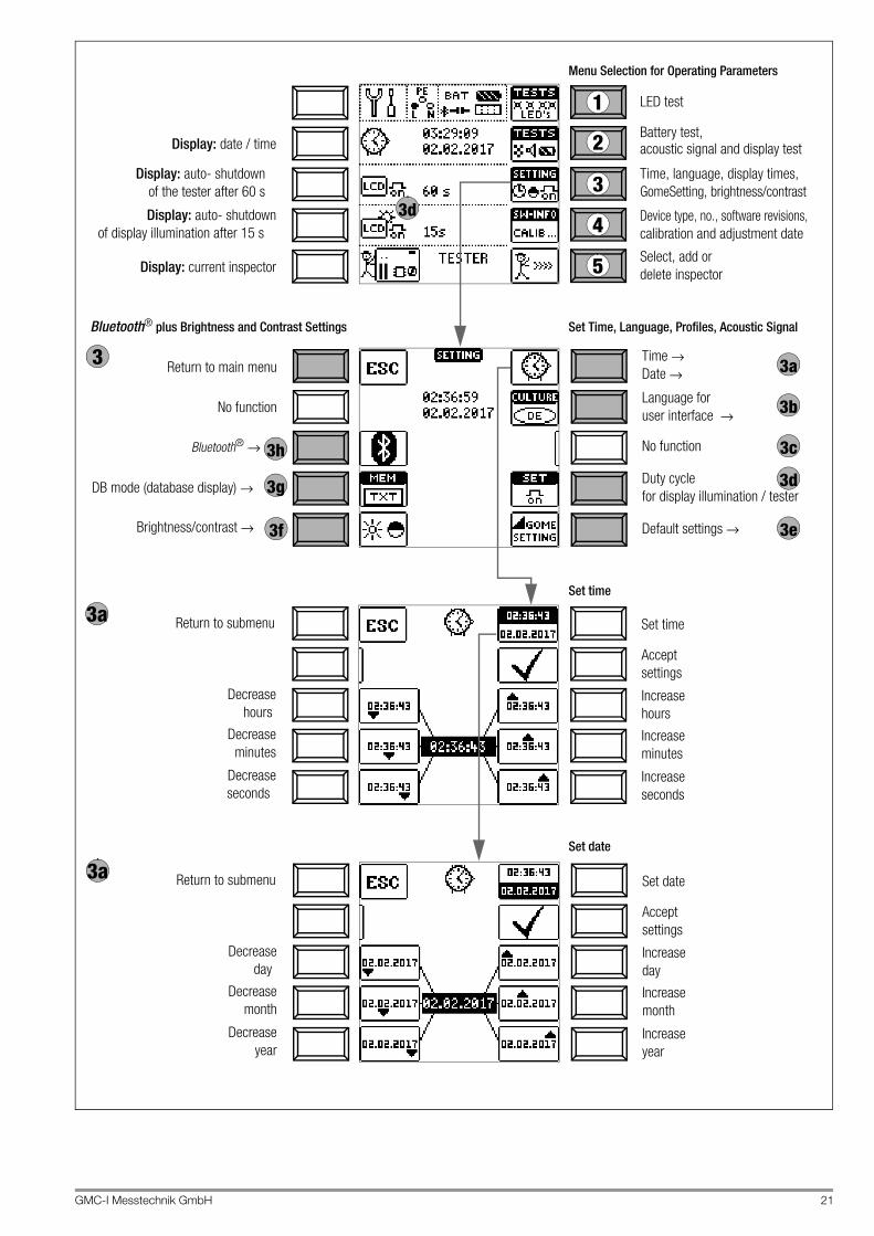
7 Device Settings – Setup
Device parameters are selected, the database and the Bluetooth interface are configured, and the firmware version is queried in this switch position.
Setup
LED test
Battery test,
Time, language, display times,
Device type, no., software revisions,calibration and adjustment date
Display: date / time
Display: auto-shutdown
Display: auto-shutdownof display illumination after 15 s
of the tester after 60 s GomeSetting, brightness/contrast
1
2
3
4
acoustic signal and display test
Return to main menu
MAINS NETZ LED: test green
MAINS NETZ LED: test red
BATT LED: test green
BATT LED: test red
No function
No function
No function
UL/RL LED: test red
RCD FI LED: test red
1
Return to main menu
Bluetooth® →
Brightness/contrast →
Time →
No function
Default settings →
Language foruser interface →
3 3a
3c
3b
3e
Date →
Duty cyclefor display illumination / tester
Return to submenu
Display Illumination On-time
Bluetooth® plus Brightness and Contrast Settings Time, On-Time and Default Settings
Menu Selection for Operating Parameters
LED tests LCD and acoustic signal tests
Test Instrument On-Time
Select, add ordelete inspector
3h
3f
5
No automatic shutdown,continuously on
DB mode (database display) → 3g
Display: current inspector
No function
3d
3d
3d
3d
Currently enabled key
Key with no current function
GMC-I Messtechnik GmbH 21
LED test
Battery test,
Time, language, display times,
Device type, no., software revisions,calibration and adjustment date
Display: date / time
Display: auto- shutdown
Display: auto- shutdownof display illumination after 15 s
of the tester after 60 s GomeSetting, brightness/contrast
1
2
3
4
acoustic signal and display test
Return to main menu
No function
Bluetooth® →
Brightness/contrast →
Time →
No function
Default settings →
Language foruser interface →
3Date →
Duty cyclefor display illumination / tester
Set time
Menu Selection for Operating Parameters
Bluetooth® plus Brightness and Contrast Settings Set Time, Language, Profiles, Acoustic Signal
Set date
Set time
Increase
Increase
hours
Accept settings
minutes
3a
Increaseseconds
Return to submenu
Decrease
Decrease
hours
minutes
Decreaseseconds
Set date
Increase
Increase
day
Accept settings
month
3a
Increaseyear
Return to submenu
Decrease
Decrease
day
month
Decreaseyear
Select, add ordelete inspector
3h
3f
5Display: current inspector
DB mode (database display) → 3g
3d
3a
3c
3b
3e
3d

22 GMC-I Messtechnik GmbH
Significance of Individual Parameters
LED testThe LEDs on the test instrument and their various sta-tuses can be checked here (red or green). Beyond this, testing of the three key functions (measurement, trig-ger and save key) can be tested here for I-SK4 or I-SK12 probes (optional accessories).
Battery Test, Acoustic Signal and Display Test
Submenu: Battery Level QueryIf battery voltage has dropped to 9.6 V or less, the UL/RL LED lights up red and an acoustic signal is generated as well.
NoteMeasuring Procedure If battery voltage drops to below 9 6 V during a measuring procedure, this is indicated by means of a popup window as well as an acoustic signal. Measured values are invalid. The measurement results cannot be saved to memory.
➭ Press ESC in order to return to the main menu.
Time/Date, User Language, Shutdown Times, Default Settings , Brightness/Contrast, Database Mode, Bluetooth
Attention!!Data loss after restoring default settings! Back up your structures, mea-surement data and se-quences to a PC before pressing the respective key. The prompt window shown at the right asks you to confirm deletion.
Time and Date Settings See page 21 for settings.
User Interface Language (CULTURE) ➭ Select the desired country setup with the appropri-
ate country code.
No Function
Test Instrument / Display Illumination On-Time The period of time after which the test instrument and LCD illumi-nation are automatically shut off can be selected here. This selec-tion has a considerable influence on the service life and the charging status of the batteries.
Display Illumination On-Time The period of time after which LCD illumination is automatically shut off can be selected here. This selection has a considerable influence on the service life and the charging status of the batter-ies.
Default Settings (GOME SETTING) The test instrument is returned to its original default set-tings when this key is activated.
Adjusting Brightness and Contrast
DB-MODE – Display of the Database in the Text or ID Mode
Creating Structures in the TXT MODEThe database in the test instrument is set to the text mode as a default feature and “TXT” appears in the header. You can create structure elements in the test instrument and label them in plain text, e.g. Cus-tomer XY, Distributor XY and Circuit XY.
Creating Structures in the ID MODEYou can work in the ID MODE as an alternative, in which case “ID” appears in the header. You can create structure elements in the test instrument and label them with any desired ID numbers.
NoteStructures can be created in the test instrument in either the text mode or the ID mode. In contrast to this, designations and ID numbers are always assigned in the report generating program.
If no texts or ID numbers have been entered to the test instrument when creating structures, the report generating program creates the missing entries automatically. These can then be edited in the report generating program and transferred back to the test instru-ment if required.
1
2
Battery test
Acoustic
Pixel test,
Pixel test,
Pixel test
Pixel test,inverted
bright
dark
signal test
3
3a
3b
3c
3d
3d
3e
3f
Jump back to
Increase brightness
Decrease brightness
Increase contrast
Decrease contrast
previous menu
3g
GMC-I Messtechnik GmbH 23
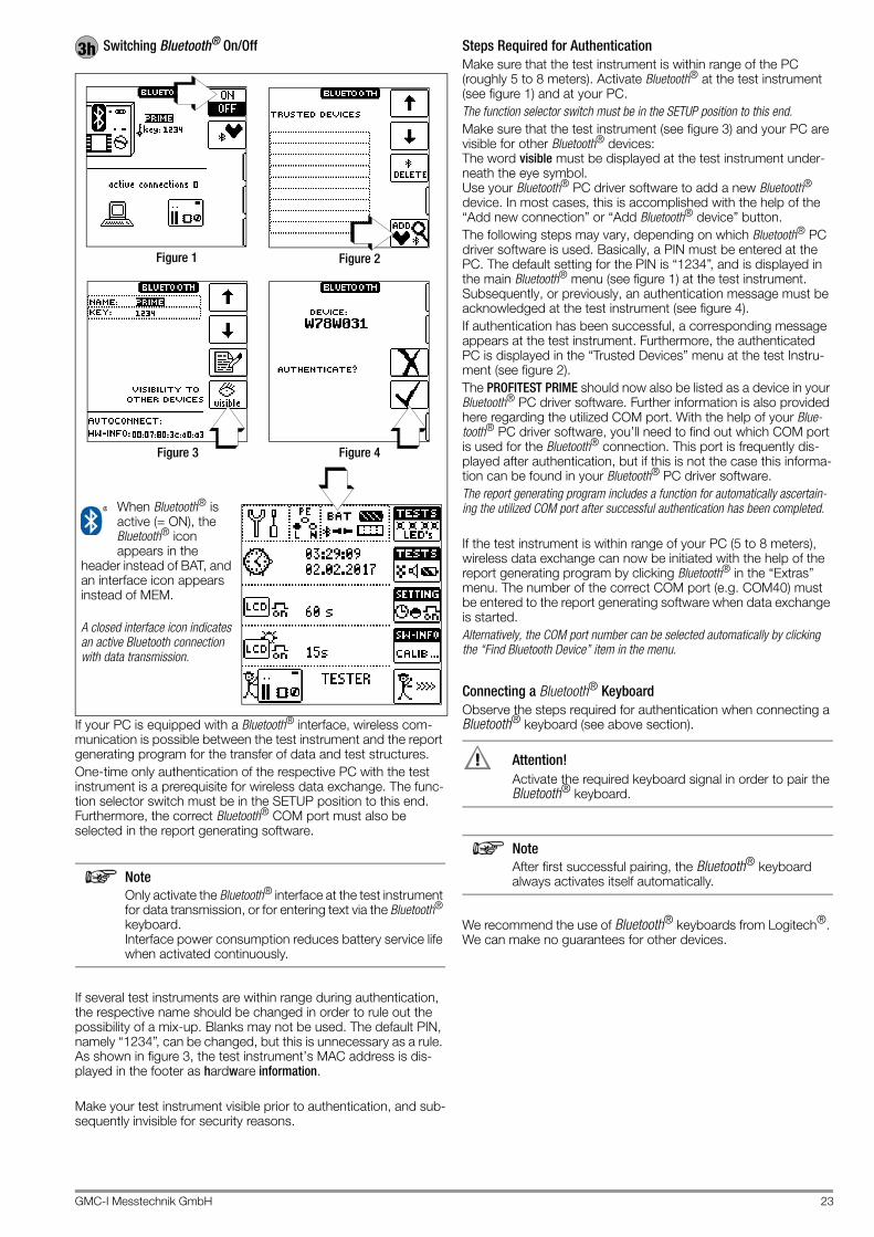
Switching Bluetooth® On/Off
If your PC is equipped with a Bluetooth® interface, wireless com-munication is possible between the test instrument and the report generating program for the transfer of data and test structures.One-time only authentication of the respective PC with the test instrument is a prerequisite for wireless data exchange. The func-tion selector switch must be in the SETUP position to this end. Furthermore, the correct Bluetooth® COM port must also be selected in the report generating software.
NoteOnly activate the Bluetooth® interface at the test instrument for data transmission, or for entering text via the Bluetooth® keyboard. Interface power consumption reduces battery service life when activated continuously.
If several test instruments are within range during authentication, the respective name should be changed in order to rule out the possibility of a mix-up. Blanks may not be used. The default PIN, namely “1234”, can be changed, but this is unnecessary as a rule. As shown in figure 3, the test instrument’s MAC address is dis-played in the footer as hardware information.
Make your test instrument visible prior to authentication, and sub-sequently invisible for security reasons.
Steps Required for AuthenticationMake sure that the test instrument is within range of the PC (roughly 5 to 8 meters). Activate Bluetooth® at the test instrument (see figure 1) and at your PC.The function selector switch must be in the SETUP position to this end.Make sure that the test instrument (see figure 3) and your PC are visible for other Bluetooth® devices: The word visible must be displayed at the test instrument under-neath the eye symbol. Use your Bluetooth® PC driver software to add a new Bluetooth® device. In most cases, this is accomplished with the help of the “Add new connection” or “Add Bluetooth® device” button.The following steps may vary, depending on which Bluetooth® PC driver software is used. Basically, a PIN must be entered at the PC. The default setting for the PIN is “1234”, and is displayed in the main Bluetooth® menu (see figure 1) at the test instrument. Subsequently, or previously, an authentication message must be acknowledged at the test instrument (see figure 4). If authentication has been successful, a corresponding message appears at the test instrument. Furthermore, the authenticated PC is displayed in the “Trusted Devices” menu at the test Instru-ment (see figure 2).The PROFITEST PRIME should now also be listed as a device in your Bluetooth® PC driver software. Further information is also provided here regarding the utilized COM port. With the help of your Blue-tooth® PC driver software, you’ll need to find out which COM port is used for the Bluetooth® connection. This port is frequently dis-played after authentication, but if this is not the case this informa-tion can be found in your Bluetooth® PC driver software.The report generating program includes a function for automatically ascertain-ing the utilized COM port after successful authentication has been completed.
If the test instrument is within range of your PC (5 to 8 meters), wireless data exchange can now be initiated with the help of the report generating program by clicking Bluetooth® in the “Extras” menu. The number of the correct COM port (e.g. COM40) must be entered to the report generating software when data exchange is started.Alternatively, the COM port number can be selected automatically by clicking the “Find Bluetooth Device” item in the menu.
Connecting a Bluetooth® KeyboardObserve the steps required for authentication when connecting a Bluetooth® keyboard (see above section).
Attention!!Activate the required keyboard signal in order to pair the Bluetooth® keyboard.
NoteAfter first successful pairing, the Bluetooth® keyboard always activates itself automatically.
We recommend the use of Bluetooth® keyboards from Logitech®. We can make no guarantees for other devices.
3h
When Bluetooth® is active (= ON), the Bluetooth® icon appears in the
header instead of BAT, and an interface icon appears instead of MEM. A closed interface icon indicates an active Bluetooth connection with data transmission.
Figure 1 Figure 2
Figure 3 Figure 4

24 GMC-I Messtechnik GmbH
Device Type, No., Software Revisions, Calibration and Adjustment Date (Example)
➭ Press any key in order to return to the main menu.
Firmware Update:The layout of the test instruments makes it possible to adapt device software to the latest standards and regulations. Beyond this, suggestions from customers result in continuous improve-ment of the test instrument software, as well as new functions.In order to assure that you can take advantage of all of these ben-efits without delay, you can quickly and completely update your test instrument software on-site (see section 26.11).
Selecting, Adding or Deleting an Inspector
See also section 8.5 on page 27 regarding the entry of a text.
4 5
Add a new inspector
Accept letter/character
Select letter/character
Select letter/character
Delete letter/character
Shift: upper/lowercase letters, vowel mutations, special chars.
? Accept name
Select inspector
Select inspector
Accept inspector
Delete inspector

GMC-I Messtechnik GmbH 25
8 General Notes
8.1 Automatic Settings, Monitoring and Shut-OffThe test instrument automatically selects all operating conditions which it’s capable of determining itself. It tests line voltage and frequency. If these lie within their valid nominal ranges, they appear at the display panel. If they’re not within nominal ranges, prevailing voltage (U) and frequency (f) are displayed instead of UN and fN.Touch voltage which is induced by test current is monitored for each measuring sequence. If touch voltage exceeds the selected limit value, measurement is immediately interrupted. The UL/RL LED lights up red.If battery voltage falls below the allowable limit value the instrument cannot be switched on, or it is immediately switched off.The measurement is interrupted automatically, or the measuring sequence is blocked (except for voltage measuring ranges and phase sequence testing) in the event of:• Impermissible line voltages (< 60 V, > 253 V / > 330 V /
> 440 V or > 725 V) for measurements which require line volt-age
• Interference voltage during insulation resistance or low resis-tance measurements
• Interference voltage during a high-voltage measurement (PROFITEST PRIME AC)
• Overheating of the instrument As a rule, excessive temperatures only occur after approxi-mately 50 measurement sequences at intervals of 5 seconds, when the rotary selector switch is set to the ZLOOP position. If an attempt is made to start a measuring sequence, an appropriate message appears at the display panel.
The instrument only switches itself off automatically after comple-tion of an automatic measuring sequence, and after the predeter-mined on-time has expired (see page 22). On-time is reset to its original value as defined in the setup menu, as soon as any key or the rotary selector switch is activated.The instrument remains on for approximately 75 s in addition to the preset on-time for measurements with rising residual current in systems with selective RCDs.The instrument always shuts itself off automatically!
8.2 Measured Value Display and MemoryThe following items appear at the display panel:• Measured values with abbreviations and units of measure• Selected function• Nominal voltage• Nominal frequency• Error messagesMeasurement values for automatic measuring sequences are stored and displayed as digital values until the next measurement sequence is started, or until automatic shutdown occurs. If the upper range limit is exceeded, the upper limit value is dis-played and is preceded by the “>” symbol (greater than), which indicates measurement value overrun.
NoteThe depiction of LEDs in these operating instructions may vary from the LEDs on the actual instrument due to product improvements.
NoteSee also “Functionality of the Probes, Indication by Means of LEDs and LCD Symbols” as of page 91.
Attention!!Reversal of N and PE in a system without RCCBs cannot be detected and is not indicated by the instrument. In a system including an RCCB, the RCCB is tripped during “touch voltage measurement without RCCB trip-ping” (automatic ZLOOP measurement), if N and PE are reversed.

26 GMC-I Messtechnik GmbH
8.3 Help FunctionThe following information can be displayed for each switch posi-tion and basic function after it has been selected with the rotary selector switch:• Wiring diagram• Measuring range• Nominal range of use and measuring uncertainty• Nominal value
➭ Press the HELP key in order to query online help.➭ If several pages of help are available for the respective mea-
suring function, the HELP key must be pressed repeatedly.➭ Press the ESC key in order to exit online help.
8.4 Setting Parameters or Limit Values using RCD Measurement as an Example
1 Access the submenu for setting the desired parameter.2 Select a parameter using the ↑ or ↓ scroll key.3 Switch to the setting menu for the selected parameter with the
→ scroll key.4 Select a setting value using the ↑ or ↓ scroll key.5 Acknowledge the setting value with the ↵ key. This value is
transferred to the settings menu.6 The setting value is not permanently accepted for the respec-
tive measurement until ✓ is pressed, after which the display is returned to the main menu. You can return to the main menu by pressing ESC instead of ✓, without accepting the newly selected value.
Parameter Lock (plausibility check)Individually selected parameter settings are checked for plausibil-ity before transfer to the measurement window.If you select a parameter setting which doesn’t make sense in combination with other parameter settings which have already been entered, it’s not accepted. The previously selected parame-ter setting remains unchanged. Remedy: Select another parameter setting.
1 2
2
3
4
4
5
6
2
4
3
5
6

GMC-I Messtechnik GmbH 27
8.5 Freely Selectable Parameter Settings or Limit Values
8.5.1 Changing Existing ParametersIndividual parameters can be changed for certain measuring func-tions, i.e. adjusted within predetermined limits.The EDIT menu doesn’t appear until after switching to the right-hand column and selecting the editable parameter .
Example for RLO Measuring Function, Parameter: LIMIT RLO
1 Open the submenu for setting the desired parameter (no fig-ure, see section 8.4).
2 Select the editable parameter (identified with the icon) with the ↑ or ↓ scroll key.
3 Select the edit menu by pressing the key.
4 Select the respective characters with the left or right cursor key. The character is accepted by pressing the ↵ key. The value is acknowledged by selecting ✓ and then pressing the ↵ key.
NoteObserve the predefined limits for the new setting value. Enter any places to the right of the decimal point as well.
8.5.2 Adding New ParametersFor certain measuring functions, additional values within pre-defined limits can be added in addition to the fixed values.The EDIT menu doesn’t appear until after switching to the right-hand column.
Example for HV-AC Measuring Function – Parameter: LIMIT ILIM
1 Open the submenu for setting the desired parameter (no fig-ure, see section 8.4).
2 Select the edit menu by pressing the key.
3 Select the respective characters with the left or right cursor key. The character is accepted by pressing the ↵ key. The value is acknowledged by selecting ✓ and then pressing the ↵ key. The new parameter is added to the list.
NoteObserve the predefined limits for the new setting value. Enter any places to the right of the decimal point as well.
Select the EDIT menu.
Select value / U/M.
Select value / U/M.
↵ Accept value / U/M.
Delete characters.
✓ Save value (to list).
Select the EDIT+ menu.
Select value / U/M.
Select value / U/M.
↵ Accept value / U/M.
Delete characters.
✓ Save value (to list).

28 GMC-I Messtechnik GmbH
8.6 2-Pole Measurement with Fast or Semiautomatic Polarity Reversal
Fast, semiautomatic polarity reversal is possible for the following measurements:• Voltage measurement U
No device-internal polarity reversal takes place – the display is only for the purpose of documentation.
• Loop impedance measurement ZLOOP
• Insulation resistance measurement RISO
• Dielectric strength test HV AC (PROFITEST PRIME AC only)
Fast Polarity ReversalThe polarity parameter is set to AUTO.Fast and convenient switching amongst all polarity variants with-out switching to the parameter settings submenu is possible by pressing the IΔN key at the instrument or on the optional I-SK4/12-PROFITEST PRIME probe (Z506T/U).
Semiautomatic Polarity Reversal in Memory ModeThe polarity parameter is set to AUTO.If testing is to be conducted with all polarity variants, automatic polarity switching takes place after each measurement after sav-ing.Polarity variants can be skipped by pressing the IΔN key at the instrument or on the optional I-SK4/12 probe.
NoteThe I-SK4 and I-SK12 (Z506T/U) test probes are available as optional accessories.L1-PE
L2-PEL3-PEN-PE
L+N-PEL1-NL2-NL3-N
L1-L2L2-L3L1-L3
ZLOOP RISO
L1-PEL2-PEL3-PEN-PEL1-NL2-NL3-N
L1-L2L2-L3L1-L3
U
Key I
L1-PEL2-PEL3-PEL1-NL2-NL3-N
L1-L2L2-L3L1-L3
L-N
Z506T/U
L1-PEL2-PEL3-PE
HV ACZ506V
L1-PEL2-PEL3-PEL1-NL2-NL3-N
L1-L2L2-L3L1-L3
L-N
L1-PEL2-PEL3-PEN-PE
L+N-PEL1-NL2-NL3-N
L1-L2L2-L3L1-L3
ZLOOP RISO
L1-PEL2-PEL3-PEN-PEL1-NL2-NL3-N
L1-L2L2-L3L1-L3
U
Z506T/U
L1-PEL2-PEL3-PE
HV AC
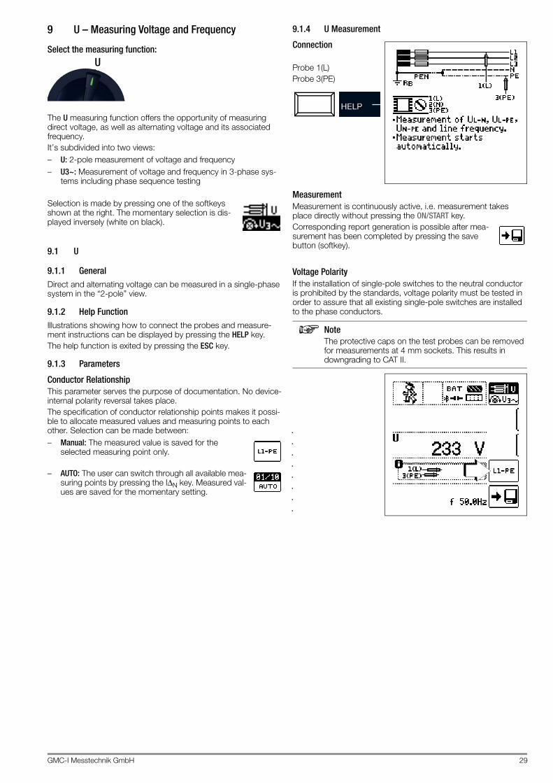
GMC-I Messtechnik GmbH 29
9 U – Measuring Voltage and Frequency
Select the measuring function:
The U measuring function offers the opportunity of measuring direct voltage, as well as alternating voltage and its associated frequency.It’s subdivided into two views:– U: 2-pole measurement of voltage and frequency– U3~: Measurement of voltage and frequency in 3-phase sys-
tems including phase sequence testing
Selection is made by pressing one of the softkeys shown at the right. The momentary selection is dis-played inversely (white on black).
9.1 U
9.1.1 GeneralDirect and alternating voltage can be measured in a single-phase system in the “2-pole” view.
9.1.2 Help FunctionIllustrations showing how to connect the probes and measure-ment instructions can be displayed by pressing the HELP key.The help function is exited by pressing the ESC key.
9.1.3 Parameters
Conductor RelationshipThis parameter serves the purpose of documentation. No device-internal polarity reversal takes place.The specification of conductor relationship points makes it possi-ble to allocate measured values and measuring points to each other. Selection can be made between:– Manual: The measured value is saved for the
selected measuring point only.
– AUTO: The user can switch through all available mea-suring points by pressing the IΔN key. Measured val-ues are saved for the momentary setting.
9.1.4 U Measurement
Connection
Probe 1(L)Probe 3(PE)
MeasurementMeasurement is continuously active, i.e. measurement takes place directly without pressing the ON/START key.Corresponding report generation is possible after mea-surement has been completed by pressing the save button (softkey).
Voltage PolarityIf the installation of single-pole switches to the neutral conductor is prohibited by the standards, voltage polarity must be tested in order to assure that all existing single-pole switches are installed to the phase conductors.
NoteThe protective caps on the test probes can be removed for measurements at 4 mm sockets. This results in downgrading to CAT II.
U

30 GMC-I Messtechnik GmbH
9.2 U3~
9.2.1 GeneralIf “U3~” is selected via softkey, voltage, frequency and phase sequence can be measured in 3-phase systems.
9.2.2 Help FunctionIllustrations showing how to connect the probes and measure-ment instructions can be displayed by pressing the HELP key.The help function is exited by pressing the ESC key.
9.2.3 U3~ Measurement
Connection L1: probe 1(L)L3: probe 2(N)L2: probe 3(PE)
MeasurementMeasurement is continuously active, i.e. measurement takes place directly without pressing the ON/START key.Corresponding report generation is possible after mea-surement has been completed by pressing the save button (softkey).
Direction of rotation is indicated by means of the following dis-plays:
9.2.4 Notes:– As a rule, clockwise rotation is required at 3-phase electrical
outlets.– Various adapters are available as accessories for measure-
ments at CEE outlets.– Measurement instrument connection is usually problematic
with CEE outlets due to contact problems. Measurements can be executed quickly and reliably without contact problems with the help of the Z500A variable plug adapter set available from GMC.
– Connection for 3-wire measurement: L1-L2-L3 at plug in clockwise direction as of PE socket
NoteSee section 24 regarding all indications for the mains connection test.
Clockwise Rotation Counterclockwise Rotation

GMC-I Messtechnik GmbH 31
10 RLO – Measuring Low-Value Resistance
10.1 RLO 0.2A – Measuring Low-Value Resistance with 0.2 A Test Current
Select the measuring function:
10.1.1 GeneralIn accordance with IEC 60364-6/DIN VDE 0100-600, the conti-nuity of protective conductors (including the equipotential bond-ing conductor via the main grounding busbar and the additional equipotential bonding conductor) and active conductors in final ring circuits must be tested.
Measurement PrincipleContinuity of conductors is ascertained by means of a constant test current and voltage drop at the device under test.
NoteIf direct voltage is used as the test voltage, DIN EN 61557-4 specifies performance of the measure-ment with polarity reversal. And thus measurement must be performed with (auto-matic) polarity reversal of the measuring voltage or with the flow of current in one direction (+ pole to PE) and then the other (- pole to PE).
10.1.2 Help FunctionIllustrations and measurement instructions can be displayed by pressing the HELP key.After measurement has been completed, the associated cable lengths for various cable cross-sections can be displayed based on the measured value by pressing the HELP key. The help function is exited by pressing the ESC key.
10.1.3 Parameters
Test SignalThe test signal can be selected here based on the following crite-ria:– Function: constant or ramp– Polarity: positive +, negative –, automatic polarity reversal ±
Test Duration – Measuring Times
Limits – Setting the Limit Value
The limit value for resistance can be set as desired. If measured values occur which are above this limit value, the red UL/RL LED lights up. Limit values can be selected within a range of 0.10 Ω to 10.0 Ω (editable). The limit value is displayed above the measured value.
RLO0.2A
Polarity: +/- to PE
Polarity: +/- to PE with ramp sequence
AUTO: measurement is ended after the measured value has been acquired. Continuous measurement is possi-ble by pressing and holding ON/START.1 min: test duration of 1 minute5 min: test duration of 5 minutes
Limit value:
RLO > limit value
UL / RL

32 GMC-I Messtechnik GmbH
10.1.4 ROFFSET Measurement
Attention!!The low-resistance measurement may only be con-ducted at voltage free devices under test or system components. Contact the measuring point first and then start the measurement!
Connection
Probe 1(L)Probe 3(PE)
Compensation for Measurement Cables up to 10 ΩThe ROFFSET function provides the user with the opportunity of deducting the resistance of extension cords in advance which are used in addition to the probe cables, in order to avoid distorted measurements. This value is deducted from the measurement result.
ROFFSET Measurement Description➭ Activate the ROFFSET function by pressing the cor-
responding softkey. ➭ ROFFSET = 0.00Ohm is displayed.➭ Select the test signal with which you intend to
conduct the measurement.➭ Then short circuit the measurement cables.➭ Start measurement by pressing the IΔN key.➭ An intermittent acoustic signal is gen-
erated and the message shown at the right is displayed.
➭ The measuring procedure is started by once again pressing the IΔN key.
The procedure can be aborted by press-ing ON/START or ESC.
NoteIf offset measurement is stopped upon appearance of a pop-up error window (Roffset > 10 Ω or difference between RLO+ and RLO– greater than 10%), the last measured offset value is retained. Inadvertent deletion of a previously ascertained offset value is thus practically ruled out! The respectively smaller value is otherwise stored to memory as an offset value. The maximum offset value is 10.0 Ω. Negative resistances may result due to the offset value.
Measuring ROFFSET
The following must be observed:– The acquired ROFFSET value is deleted when the test signal is
changed or if the function is deactivated.– If an error message appears, the last acquired, valid value is
retained.– As a result of the utilized 4-wire technology, resistance of the
probe cables does not have to be calculated into the mea-surement results.
NoteExtension Cords Only use this function when working with extension cables. When different extension cables are used, the above described procedure must always be repeated.
ROFFSET: ON ↔ OFF

GMC-I Messtechnik GmbH 33
10.1.5 RLO 0.2 A Measurement
Attention!!The low-resistance measurement may only be con-ducted at voltage free devices under test or system components. Contact the measuring point first and then start the measurement!
Attention!!Measurement results may be distorted due to parallel connected impedances and equalizing current.
Start the measurement.
Press and hold for long-term measurement.
– Save: possible via softkey after successful measurement
Attention!!The test probes should always be in contact with the DUT be-fore the start key ▼ is activated. If the object is energized, measurement is disabled as soon as it’s contacted with the test probes. If the start key ▼ is pressed first and the test object is con-tacted with the test probes afterwards, the device fuse blows.
Automatic Polarity ReversalAfter the measuring sequence has been started, the instrument performs measurement with automatic polarity reversal – first with current flow in one direction, and then in the other. In the case of long-term measurement (press and hold the ON/START key), polar-ity is switched once per second.If the difference between RLO+ and RLO– is greater than 10% with automatic polarity reversal, RLO+ and RLO– values are dis-played instead of RLO. The respectively larger value, RLO+ or RLO–, appears at the top and is saved to the database as the RLO value.
The measured values are displayed after test time has elapsed in accordance with the following table:
All four values are always saved: Rlo, Rlo+, Rlo- and Roffset.
Evaluating Measurement ResultsDiffering results for measurements in both directions indicate volt-age at the DUT (e.g. thermovoltages or unit voltages). Measurement results can be distorted by parallel connected impedances in load current circuits and by equalizing current, especially in systems which make use of “overcurrent protection
devices” (previous neutralization) without an isolated protective conductor. Resistances which change during measurement (e.g. inductance), or a defective contact, can also cause distorted measurements (double display).In order to assure unambiguous measurement results, causes of error must be located and eliminated.In order to find the cause of the measuring error, measure resis-tance in both current flow directions.
The instrument’s batteries are exposed to excessive stress during insulation resistance measurement. For measurement with cur-rent flow in one direction, only press and hold the ON/START ▼ key as long as is necessary for the measurement.
NoteMeasuring Low-Value Resistance Measurement cable and 2-pole measuring adapter resis-tance is compensated for automatically thanks to the four conductor method and do not effect measurement results. However, if an extension cord is used its resistance must be measured and deducted from the measurement results. Resistances which do not demonstrate a stable value until after a “settling in period” should not be measured with automatic polarity reversal, but rather one after the other with positive and negative polarity. Examples of resistances whose values may change during measurement include: – Incandescent lamp resistance, whose values change
due to warming caused by test current – Resistances with a great conductive component – Contact resistance – Line reactors
Calculation of Cable Lengths for Common Copper ConductorsIf the HELP key is activated after performance of resistance mea-surement, the cable lengths corresponding to common conduc-tor cross-sections are displayed.
If results vary for the two different current flow directions, cable length is not displayed. In this case, capacitive or inductive com-ponents are apparently present which would distort the calcula-tion.This table only applies to cables made with commercially available copper conductors and cannot be used for other materials (e. g. aluminum)!
10.1.6 Evaluation of Measured ValuesSee tables in section 27.1.
Polarity Selection Display Condition+ pole to PE RLO+ None
– pole to PE RLO– None
± pole to PERLO Where ΔRLO ≤ 10%RLO+ RLO– Where ΔRLO > 10%

34 GMC-I Messtechnik GmbH
10.1.7 RLO 0.2A Measurement at PRCDs
ApplicationsProtective conductor current is monitored for certain types of PRCDs. Direct activation or deactivation of the test current required for protective conductor resistance measurements of at least 200 mA results in tripping of the PRCD and thus to interrup-tion of the protective conductor connection. Protective conductor measurement is no longer possible in this case.A special ramp sequence for test current activation or deactivation in combination with the PROFITEST PRCD test adapter permits protective conductor resistance measurement without tripping the PRCD.
Measuring Procedure– Connection: Refer to the operating instructions for the
PROFITEST PRCD adapter.– Parameters: Select the ramp sequence and the limit value.– Activate the PRCD.– ROFFSET measurement: see section 10.1.4.– RLO 0.2A measurement: press ON/START (see also section
10.1.5).– Save: possible via softkey after successful measurement
NotePoor contacting with the test probes results in fluctuating test current and leads to interruption of the measurement and display of the popup message shown at the right.
Ramp Function Time SequenceDue to the physical characteristics of the PRCD, measuring times for this ramp function amount to several seconds.If test current polarity is revered, additional waiting time is also required during polarity reversal. This is programmed into the test sequence in the “automatic polarity reversal” operating mode.Revers polarity manually, e.g. from “+pole with ramp” to “-pole with ramp” . The test instrument then detects the reversal of current flow direction, stops measurement for the required waiting time and simultaneously displays a corresponding message (see figure at right).
Representation of Measuring and Waiting Times for Protective Conductor Resistance Measurement at PRCDs with the PROFITEST PRIME
PRCD Tripping due to Poor ContactingGood contact must be assured between the test probes and the device under test or the sockets at the PROFITEST PRCD test adapter during measurement. Interruptions can result in consider-able test current fluctuation which causes the PRCD to trip under unfavorable conditions. If this is the case, tripping of the PRCD is automatically detected by the test instru-ment and indicated by a corresponding error message (see figure at the right). In this case as well, the test instrument automatically takes subsequently required waiting time into account before you can reactivate the PRCD and start the measurement over again.
Connection➭ Read the operating instructions for the PROFITEST PRCD
adapter, in particular section 4.1. It includes connection in-structions for offset measurement and for protective conduc-tor resistance measurement.
Selecting the Polarity Parameter ➭ Select the desired polarity parameter with ramp.
Measuring ROFFSET
➭ Perform offset measurement as described in section 10.1.4, in order to assure that the test adapter’s connector contacts are not included in the measurement results.
Measuring Protective Conductor Resistance➭ Determine whether or not the PRCD is activated. If not, acti-
vate it.➭ Perform protective conductor measurement as described in
section 10.1.5 above. Start the test sequence by briefly press-ing the ON/START key. The predetermined duration of the mea-suring phase can be extended by pressing and holding the ON/START key.
Attention!!The low-resistance measurement may only be con-ducted at voltage free devices under test or system components. Use the PROFITEST PRCD test adapter (M512R) for testing PRCDs after carefully reading the op-erating instructions.
Start the measurement.
The symbol shown at the right appears during the mag-netization phase (rising curve) and the subsequent mea-suring phase (constant current). If measurement is aborted already during the rising phase, no mea-surement results can be ascertained or displayed.After measurement, the demagnetization phase (falling curve) and subsequent waiting time are indicated by the inverted symbol shown at the right. No new measure-ments can be started during this time. Measurement results cannot be read and measurement with the same or another polarity cannot be started until the symbol at the right appears.
Measuring Phase Demagnetizingand Waiting Time
Results
Time [s]
RisingPhase
Test Current [A]
0 1 3 6
0.25 Before Polarity ReversalorRestart

GMC-I Messtechnik GmbH 35
10.2 RLO 25A – Measuring Low-Value Resistance with 25 A Test Current
Select the measuring function:
10.2.1 Measurement PrincipleContinuity of protective conductor systems is determined by applying a test current with line frequency and measuring the resultant voltage drop.Testing must be conducted between the PE terminal and various points within the protective conductor system.Due to the high amperage of the utilized test current, this type of measurement is above all suitable for precise continuity testing of especially low-resistance protective conductor systems, i.e. in the case of large cross-sections and/or short cable lengths.This type of measurement necessitates mains auxiliary power and the mains switch must be set to the ON position.Mains auxiliary power is checked to make sure it’s right before measurement is started. Permissible line voltages are 115 and 230 V, and permissible line frequencies are 50 and 60 Hz.
10.2.2 Help FunctionIllustrations and measurement instructions can be displayed by pressing the HELP key.After measurement has been completed, the associated cable lengths for various cable cross-sections can be displayed based on the measured value by pressing the HELP key. The help function is exited by pressing the ESC key.
The measurement is aborted if voltage is present at the test probes when measurement is started.* A corresponding error message appears at the display.
* This warning might also appear if continuity of the protective conductor con-nection is impaired, because in this case external voltages have been ca-pacitively induced.
10.2.3 Parameters
Limits – Low-Resistance Limit Value
The limit value of the conductor under test is configured here. This setting depends on conductor cross-section.Selection can be made between preset parameters or an adjust-able value within a range of 0 to 10 Ω.If the limit value is exceeded, the UL/RL LED lights up red.
10.2.4 ROFFSET MeasurementThe ROFFSET function provides the user with the opportunity of deducting the resistance of extension cords in advance which are used in addition to the probe cables, in order to avoid distorted measurements. This value is deducted from the measurement result.
ROFFSET Measurement Description➭ Activate the ROFFSET function by pressing the cor-
responding softkey. ➭ ROFFSET = 0.00 Ohm is displayed.➭ Select the test signal with which you intend to
conduct the measurement.➭ Then short circuit the measurement cables.➭ Start measurement by pressing the IΔN key.➭ An intermittent acoustic signal is gen-
erated and the message shown at the right is displayed.
➭ The measuring procedure is started by once again pressing the IΔN key.
The procedure can be aborted by press-ing ON/START or ESC.
Test Duration – Measuring TimesTest duration is limited to 10 s. Use for intended purpose specifies a test duration of no more than10 seconds and a pause of at least 30 seconds. If this repetition rate is exceeded, the instrument may overheat in which case the measurement is disabled.
RLO25A
Limit value:
RLO > limit value
UL / RL
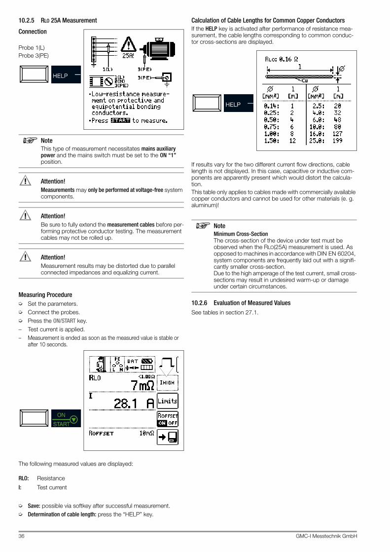
36 GMC-I Messtechnik GmbH
10.2.5 RLO 25A Measurement
Connection
Probe 1(L)Probe 3(PE)
NoteThis type of measurement necessitates mains auxiliary power and the mains switch must be set to the ON “1” position.
Attention!!Measurements may only be performed at voltage-free system components.
Attention!!Be sure to fully extend the measurement cables before per-forming protective conductor testing. The measurement cables may not be rolled up.
Attention!!Measurement results may be distorted due to parallel connected impedances and equalizing current.
Measuring Procedure➭ Set the parameters.➭ Connect the probes.➭ Press the ON/START key.– Test current is applied.– Measurement is ended as soon as the measured value is stable or
after 10 seconds.
The following measured values are displayed:
RLO: Resistance
I: Test current
➭ Save: possible via softkey after successful measurement.➭ Determination of cable length: press the “HELP” key.
Calculation of Cable Lengths for Common Copper ConductorsIf the HELP key is activated after performance of resistance mea-surement, the cable lengths corresponding to common conduc-tor cross-sections are displayed.
If results vary for the two different current flow directions, cable length is not displayed. In this case, capacitive or inductive com-ponents are apparently present which would distort the calcula-tion.This table only applies to cables made with commercially available copper conductors and cannot be used for other materials (e. g. aluminum)!
NoteMinimum Cross-Section The cross-section of the device under test must be observed when the RLO(25A) measurement is used. As opposed to machines in accordance with DIN EN 60204, system components are frequently laid out with a signifi-cantly smaller cross-section. Due to the high amperage of the test current, small cross-sections may result in undesired warm-up or damage under certain circumstances.
10.2.6 Evaluation of Measured ValuesSee tables in section 27.1.

GMC-I Messtechnik GmbH 37
11 RISO – Measurement of Insulation Resistance
11.1 Insulation Measurement with Constant Test Voltage
Select the measuring function:
11.1.1 GeneralIn order to avoid hazards or damage resulting from fault current and creepage current which can occur due to faulty cable insula-tion, IEC 60364-6/DIN VDE 0100-600 requires testing of insula-tion resistance between the active conductors and the protective conductor connected to earth.
Measurement PrincipleInsulation resistance measurement is performed by applying a constant direct voltage of 50 V to 1 kV. In accordance with DIN EN 61557-2, test current is at least 1 mA, and short-circuit current is limited to < 1.6 mA for safety reasons.
11.1.2 Help FunctionIllustrations and measurement instructions can be displayed by pressing the HELP key.The help function is exited by pressing the ESC key.
11.1.3 Parameters
Test Duration – Measuring Times
Test Voltages
Various preset parameters are available for setting test voltage. The list can be extended with the help of the editing function. This function is made available as soon as the cursor is located in the parameter selection column (see also section 8.5). This list makes it possible to select a test voltage which deviates from nominal voltage (and is usually lower) for measurements at sensi-tive components, as well as systems with voltage limiting devices.
Limits – Limit Values for Insulation Resistance
Setting a limit value for insulation resistance makes it possible to indicate that a minimum value has been fallen short of. If the mea-sured value for RISO is below this limit, the UL/RL LED lights up red. Various fixed parameters or an editable value can be selected. The limit value is displayed above the measured value.
Conductor Relationship – Polarity
The specification of conductor relationship points makes it possi-ble to allocate measured values and measuring points to each other. Corresponding report generation is possible after measure-ment has been completed by pressing the save button (softkey).Selection can be made between manual setting and the AUTO function. With the help of the AUTO function, the user can switch through the various conductor relationships, one after the other, by pressing the IΔN key (see also section 8.6).
RISO
AUTO: measurement is ended after the measured value has been acquired. Continuous measurement is possi-ble by pressing and holding ON/START.1 min: test duration of 1 minute5 min: test duration of 5 minutes
Limit value:
RISO < Limit value
UL / RL
2-Pole Measurement (selection relevant for report generation only):

38 GMC-I Messtechnik GmbH
11.1.4 RISO Measurement
Connection
Probe 1(L)Probe 3(PE)
NoteN and PE must be interrupted for systems without RCD.
NoteChecking Measurement Cables Before Measurements Before performing insulation measurement, the test probes on the measurement cables should be short-cir-cuited in order to assure that the instrument displays a value of less than 1 kΩ. In this way, incorrect connection can be avoided and broken measurement cables can be detected.
Attention!!Insulation resistance may only be measured at voltage-free devices.
Attention!!Do not touch the test probes during the measurement – danger of injury!
Attention!!Capacitive devices under test are charged during this measurement. Incorrect discharging results in a life-threatening situation. For this reason, the connection be-tween the test instrument and the device under test may not be interrupted until voltage at the test probes has dropped to below 10 V.
Measuring Procedure– Connect probes.– Set parameters.– Start: Press the ON/START key.– Constant test voltage is applied.– Measured values are display when the measured value for RISO
is stable or test time has elapsed.– Measurement is ended as soon as U is less than 10 V.
Continuous measurement: Press and hold ON/START with ton = AUTO setting.
Quick polarity reversal if parameter is set to AUTO: 01/11 ... 11/11: L1-PE ... L1-L3The measurement can be aborted by pressing ON/START or ESC.
The following measured values are displayed:– RISO: insulation resistance– U: momentary voltage at the test probes– UISO: voltage at the moment insulation resistance was
acquired
The following points must be observed:– High cable capacitance extends measuring time.– The duration of the measurement can be increased by press-
ing and holding the ON/START key – due to the fact that the battery is subjected to a heavy load during this measurement, it should be kept as short as possible.

GMC-I Messtechnik GmbH 39
11.2 RISO Ramp – Insulation Measurement with Rising Test Voltage
Select the measuring function:
11.2.1 GeneralInsulation and semiconductor junction quality can be determined with the RISO Ramp measuring function. This function is used in the following cases:- Detection of weak points in the insulation- Function testing of voltage-sensitive components- Determination of sparkover voltage for spark gaps
Measurement PrincipleInsulation testing is conducted by applying a rising test voltage ramp which is increased continuously up to selected maximum test voltage U. If a voltage drop occurs or if maximum leakage current is exceeded, measurement is aborted and sparkover or breakdown voltage UISO is displayed.
11.2.2 Help FunctionIllustrations and measurement instructions can be displayed by pressing the HELP key.The help function is exited by pressing the ESC key.
11.2.3 Parameters
Breakdown Voltage Limit Values
Limit value ILIM can be set for the purpose of current monitoring. Measurement is aborted if the limit value is exceeded. Various fixed parameters or an editable value can be selected.
Test Voltage
Various preset parameters are available for setting test voltage. The list can be extended with the help of the editing function. This function is made available as soon as the cursor is located in the parameter selection column (see also section 8.5).
Limit – Limit Values for Breakdown Voltage
A target range can be defined by setting upper and lower limit val-ues for insulation voltage UISO. If the measured value is not within this range, the UL/RL LED lights up red. An editable value is avail-able for the adjustment of each limit value.
Conductor Relationship – Polarity
The specification of conductor relationship points makes it possi-ble to allocate measured values and measuring points to each other. Corresponding report generation is possible after measure-ment has been completed by pressing the save button (softkey).Selection can be made between manual setting and the AUTO function. With the help of the AUTO function, the user can switch through the various conductor relationships, one after the other, by pressing the IΔN key (see also section 8.6).
RISO
Limit value:
I > ILimit
UISO
STOP
Lower limit value:
Editing range:40 V ... 999 V
Upper limit value:
UISO < U (lower limit value)
UL / RL
UISO > U (upper limit value)
2-Pole Measurement (selection relevant for report generation only):

40 GMC-I Messtechnik GmbH
11.2.4 RISO Ramp Measurement
Connection
Probe 1(L)Probe 3(PE)
Attention!!Insulation resistance may only be measured at voltage-free devices.
Attention!!Do not touch the test probes during the measurement – mortal danger!
Attention!!Capacitive devices under test are charged during this measurement. Incorrect discharging results in a life-threatening situation. For this reason, the connection be-tween the test instrument and the device under test may not be interrupted until voltage at the test probes has dropped to below 10 V.
Measuring Procedure– Connect probes.– Set parameters.– Start: Press the ON/START key.– Rising test voltage is applied.– Measured values are displayed when:
– Breakdown occurs in the form of arc-over or a voltage drop or
– Nominal test voltage is reached or
– Current flows at the selected amperage– Measurement is ended as soon as U is less than 10 V.
Press briefly:
Quick polarity reversal if parameter is set to AUTO: 01/11 ... 11/11: L1-PE ... L1-L3
After pressing the ON/START key test voltage is continuously increased until specified nominal voltage UN is reached. U is the voltage which is measured at the test probes during and after test-ing. This voltage drops to a value of less than 10 V (see section entitled “Discharging the Device Under Test”).
The measurement can be aborted by pressing ON/START or ESC.
Test voltage is continuously increased until one of the following events occurs:• Breakdown in the form of arc-over or a voltage drop• Nominal voltage (selected test voltage UN) is reached• Current flows at the selected amperage• Measurement is aborted by pressing ON/START or ESC
The following measured values are displayed:– U: momentary test probe voltage– UISO: either breakdown or nominal voltage depending on the
course of test events

GMC-I Messtechnik GmbH 41
11.2.5 Notes on Measurement with the Ramp FunctionInsulation measurement with ramp function serves the following purposes:• Detect weak points in the test object’s insulation• Determine tripping voltage of voltage limiting components and
test them for correct functioning. These components may include, for example, varistors, overvoltage limiters (e.g. DEHNguard® from Dehn+Söhne) and spark gaps.
The test instrument uses continuously rising test voltage for this measuring function, up to the selected maximum voltage limit. The measuring procedure is started by pressing the ON/START key and runs automatically until one of the following events occurs:• The selected voltage limit is reached• The selected current limit is reachedor • Sparkover occurs (spark gaps)
Differentiation is made amongst the following three procedures for insulation measurement with ramp function:
Testing overvoltage limiters or varistors or determining their tripping voltage:– Select maximum voltage such that the anticipated breakdown
voltage of the device under test is roughly one third of this value (observe manufacturer’s data sheet if applicable).
– Select the current limit value in accordance with actual requirements or the manufacturer’s data sheet (characteristic curve of the device under test).
Determining tripping voltage for spark gaps:– Select maximum voltage such that the anticipated breakdown
voltage of the device under test is roughly one third of this value (observe manufacturer’s data sheet if applicable).
– Select the current limit value in accordance with actual requirements within a range of 5 to 10 μA (response charac-teristics are too unstable with larger current limit values, which may result in faulty measurement results).
Detecting weak points in the insulation:– Select maximum voltage such that it does not exceed the test
object’s permissible insulation voltage; it can be assumed that an insulation fault will occur even with a significantly lower voltage if an accordingly lower maximum voltage value is selected (nevertheless at least greater than anticipated break-down voltage) – the ramp is less steep as a result (increased measuring accuracy).
– Select the current limit value in accordance with actual requirements within a range of 5 to 10 μA (see also settings for spark gaps).
11.3 Evaluation of Measured ValuesInstrument measuring error must be taken into consideration in order to assure that the limit values set forth in DIN VDE regula-tions are not fallen short of. The required minimum display values for insulation resistance can be determined with the help of the tables in section 27.1. These values take maximum device error into consideration (under nominal conditions of use). Intermediate values can be interpolated.

42 GMC-I Messtechnik GmbH
12 RCD – Testing of Residual Current Devices
12.1 GeneralResidual current devices (RCDs) are used for protection by means of automatic shutdown of supply power in the event of indirect contact. The effectiveness of this measure must be examined by means of visual inspection and measurement. It must be verified that shutdown takes place no later than upon reaching rated dif-ferential current IN, and the agreed upon limit value for permissi-ble touch voltage must not be exceeded.
The PROFITEST PRIME offers the opportunity of testing RCDs which are sensitive to alternating, pulsed and direct current with non-delayed (general type), short-time delayed (type G) or time delayed tripping (type ).The following table provides an overview of the response charac-teristics of various types of RCDs.
Types of Residual Current
Selection is possible from the following measuring functions:– UIN: touch voltage measurement– RCD IF: measurement of tripping current with rising test current– RCD IN: measurement of time to trip with constant test current– RCD IF +IN: simultaneous measurement of time to trip and
tripping current with rising test current
Refer to section 25, “Characteristic Values”, as of page 102 when selecting the measuring function.Information regarding status information can be found in section 24.
NoteGeneration of DC Residual Current All three probes are required in this case: (1)L, (2)N and (3)PE. Two probes, namely 1(L) and 3(PE), suffice when generating AC current or half-wave current.
12.2 Measurement of Touch Voltage and Time to Trip with Nom-inal Residual Current
Select the measuring function:
12.2.1 GeneralEach of the 3 tripping tests described on the following pages begins with a touch voltage measurement for safety reasons before the actual tripping test is started. Respective maximum touch voltage UL must be specified here under limits, and must not be exceeded. If prevailing touch voltage UIN is greater than limit value UL, safety shutdown ensues.
Measuring MethodThe instrument uses a measuring current of only ⅓ nominal resid-ual current for the determination of touch voltage UIN which occurs at nominal residual current. This prevents tripping of the RCCB.This measuring method is especially advantageous, because touch voltage can be measured quickly and easily at any electrical outlet without tripping the RCCB.The usual, complex measuring method involving testing for the proper functioning of the RCD at a given point, and subsequent substantiation that all other systems components requiring pro-tection are reliably connected at low resistance values to the selected measuring point via the PE conductor, is made unneces-sary.
Attention!!In order to prevent the loss of data in data processing systems, perform a data backup before starting the measurement and switch off all consumers.
12.2.2 Help FunctionIllustrations and measurement instructions can be displayed by pressing the HELP key.The help function is exited by pressing the ESC key.
12.2.3 ParametersThe nominal residual current IN parameter, which is relevant for touch voltage, can be set in the following submenu:
AC A F B/B+ A – EV B/B+MI
Sinusoi-dal X X X X X X
Half-wave — X X X X X
DC — — — X — X
+ 6 mA DC — — — — X X
S
RCD IΔN
RCD IF
RCD IF + IΔN
Nominal residual current: 10 ... 1000 mA

GMC-I Messtechnik GmbH 43
Limit ValuesThe test instrument offers the option of a display in the event that maximum permissible touch voltage UL is exceeded.UL can be configured to this end.If prevailing touch voltage UIN is greater than limit value UL, safety shutdown ensues. The UL/RL LED lights up red.
12.2.4 RCD IΔN – Measurement of Time to Trip with Nominal Current
Measuring ConnectionsMeasurement with full and half-wave:Probe 1(L)Probe 3(PE)
Measurement with direct current:Probe 1(L)Probe 2(N)Probe 3(PE)
Refer to the notes in section 12.7 when performing the measure-ment.
Measuring Procedure➭ Set the parameters.➭ Start touch voltage measurement:
Press the ON/START key.– Display of measured values: UIN, RE, U, f➭ Start touch voltage measurement and tripping test:
Press the IN key.– Test current is applied.– Measurement is ended when the RCD is tripped or the final
value is reached.– Display of measured values: UIN, ta, RE, U, f
Start the measurement.
Measurement can be aborted by pressing ON/START, IN or ESC.
The following measured values are displayed:– UIN: touch voltage relative to nominal residual current– ta: time to trip– RE: earth loop resistance– U: voltage at the test probes before stating the tripping test – UN is
displayed if voltage value Umax. deviates from nominal volt-age by 10%.
– f: frequency of the voltage at the test probes before starting the tripping test – fN is displayed if frequency fmax. deviates from nominal frequency by 1%.
Tripping Test with Nominal Residual CurrentThe tripping test need only be performed at one measuring point for each RCCB. If touch voltage UIN reaches a value of greater than UL during the measurement, safety shutdown ensues.
Unintentional Tripping of the RCD due to Bias Current within the SystemAny bias current which might occur can be ascertained as described in section 18 on page 70 with the help of a current clamp transformer. The RCCB may be tripped during the testing of touch voltage if extremely large bias currents are present within the system, or if a test current was selected which is too great for the RCCB.After touch voltage has been measured, testing can be performed to determine whether or not the RCCB is tripped within the selected time limit values at nominal residual current.
Unintentional Tripping of the RCD due to Leakage Current in the Measuring CircuitMeasurement of touch voltage with 30% nominal residual current does not normally trip an RCCB. However, the tripping limit may be exceeded as a result of leakage current in the measuring cir-cuit, e.g. due to interconnected consumers with EMC circuit such as frequency converters and PCs.
Limit Values for Allowable, Continuous Touch VoltageThe limit for allowable, continuous touch voltage is equal to UL = 50 V for alternating voltages (international agreement). Lower values have been established for special applications (e.g. medical applications: UL = 25 V).
Attention!!If touch voltage is too high, or if the RCCB is not tripped, the system must be repaired (e.g. earthing resistance is too high, defective RCCB etc.)!
3-Phase ConnectionsFor proper RCD testing at three-phase connections, the tripping test must be conducted for one of the three phase conductors (L1, L2 or L3).
Inductive Power ConsumersVoltage peaks may occur within the measuring circuit if inductive consumers are shut down during an RCCB trip test. If this is the case, the test instrument might not display any measured value ( – – – ). If this message appears, switch all consumers off before performing the tripping test. In extreme cases, one of the fuses in the test instrument may blow, and/or the test instrument may be damaged.
Touch voltage:

44 GMC-I Messtechnik GmbH
12.3 RCD IF – Testing Residual Current Devices by Measuring Tripping Current with Rising Test Current
Select the measuring function:
12.3.1 GeneralThis test instrument offers the option of testing type B RCDs with smooth direct current.DIN EN 61557-6 requires testing of these RCDs in both current flow directions.Other RCDs can be selected under the test object parameter, and other waveforms can be selected under the Test parameter.
Measurement PrincipleThe tripping current of RCDs is measured by applying a rising test current.
12.3.2 Help FunctionIllustrations and measurement instructions can be displayed by pressing the HELP key.The help function is exited by pressing the ESC key.
12.3.3 ParametersThe measurement parameters can be set in the submenus which are described below:
Test Object ParameterThe following characteristic values can be configured for the device under test:– IN: nominal residual current – Type of device, e.g. RCD, RCD-S– Characteristic, e.g. type AC, type B– IN: nominal current
Test ParametersThe type of test current can be selected. The function’s starting and final values are dictated by this setting (see also section 25, “Characteristic Values”, as of page 102).Selection is possible from the following options:– Full-wave, 0°– Positive half-wave– Negative half-wave– Positive direct current– Negative direct current
The type of electrical system can be selected for report genera-tion:– TN/TT– IT
Limit ValuesThe test instrument offers the option of displaying limit value viola-tions.The following limit values can be configured:– UL: maximum permissible touch voltage– IΔ:>: minimum tripping current– IΔ:<: maximum tripping currentIf touch voltage UIN is greater than limit value UL, safety shutdown ensues. The UL/RL LED lights up red. If the measured value for tripping current IΔ is not within the spec-ified limits, the RCD FI LED lights up red.
RCD IF
Nom. res. current:
Type 1: RCD, SRCD, PRCD etc.
Nominal current: 6 ... 125 A
Type 2: AC , A/F , B/B+ *, EV/MI
* Type
10 ... 1000 mA
B/B+/EV/MI = AC/DC sensitive
SinusoidalNegative/positive half-wave
Waveform:
Positive/negative direct current
System type:TN/TT, IT
Touch voltage:
Tripping limit values:

GMC-I Messtechnik GmbH 45
12.3.4 RCD IF Measurement
Connection Measurement with full and half-wave:Probe 1(L)Probe 3(PE)
Measurement with direct current:Probe 1(L)Probe 2(N)Probe 3(PE)
NoteHalf-wave test: Testing is conducted with rising test current with up to 1.4 x IN. Setting the tripping current factor has no effect.
Refer to the notes in section 12.7 when performing the measure-ment.
Measuring Procedure➭ Set the parameters.➭ Start touch voltage measurement:
Press the ON/START key.– Display of measured values: UIN, RE, U, f➭ Start touch voltage measurement and tripping test: Press the
IN key.– Test current is applied.– Measurement is ended when the RCD is tripped or the final
value is reached.– Display of measured values: UIN, IΔ, RE, U, f
The following measured values are displayed:– UIN: touch voltage relative to nominal residual current– IΔ: residual tripping current– RE: earth loop resistance– U: voltage at the test probes before starting the tripping test,
UN is displayed if voltage Umax. deviates from nominal voltage by 10%
– f: frequency of the applied voltage, fN is displayed if frequency fmax. deviates from nominal fre-quency by 1%
Start the measurement.
Measurement can be aborted by pressing ON/START, IN or ESC.

46 GMC-I Messtechnik GmbH
12.4 RCD IΔN – Testing RCDs by Measuring Time to Trip with Constant Test Current
Select the measuring function:
12.4.1 GeneralThis measuring function makes it possible to test RCDs with sinu-soidal test current in accordance with DIN EN 61557-6. Other waveforms can be selected under the Test parameter.
Measurement PrincipleVery high constant test current is applied and time to trip, or hold-ing time in the event that tripping does not occur, is measured.
12.4.2 Help FunctionIllustrations and measurement instructions can be displayed by pressing the HELP key.The help function is exited by pressing the ESC key.
12.4.3 ParametersThe measurement parameters can be set in the submenus which are described below:
Test Object ParameterThe following characteristic values can be configured for the device under test:– IN: nominal residual current – Type of device, e.g. RCD, RCD-S– Characteristic, e.g. type AC, type B– IN: nominal current
One of the following waveforms can be selected for the test cur-rent to be applied:– Full-wave, 0°– Full-wave, 180°– Positive half-wave– Negative half-wave– Positive direct current– Negative direct current
Selection options for the tripping current factor:– 0.5 x IN + 1 x IN: no-trip test with half nominal residual cur-
rent (duration: 1 s) with subsequent tripping test with nominal residual current
– 1 x IN: tripping test with nominal residual current– 2 x IN: tripping test with 2 times nominal residual current– 5 x IN: tripping test with 5 times nominal residual current
The type of electrical system can be selected for report genera-tion:– TN/TT– IT
Limit ValuesThe test instrument offers the option of displaying limit value viola-tions.The following limit values can be configured:– UL: maximum permissible touch voltage– ta>: minimum time to trip– ta<: maximum time to tripIf touch voltage UIN is greater than limit value UL, safety shutdown ensues. The UL/RL LED lights up red. If the measured value for time to trip ta is not within the specified limits, the RCD FI LED lights up red.
RCD IΔN
Nom. res. current:
Type 1: RCD, SRCD, PRCD etc.
Nominal current: 6 ... 125 A
Type 2: AC , A/F , B/B+ *, EV/MI
10 ... 1000 mA
* Type B/B+/EV/MI = AC/DC sensitive
Phase displacement: 0°/180°
X times tripping current:
Negative/positive half-waveNegative/positive direct current
1, 2, 5 (IΔN max. 300 mA)
Waveform:
System type:TN/TT, IT
Touch voltage:
Time to trip:
< 25 V, < 50 V, < 65 V

GMC-I Messtechnik GmbH 47
12.4.4 RCD IΔN Measurement
Connection Measurement with full and half-wave:Probe 1(L)Probe 3(PE)
Measurement with direct current:Probe 1(L)Probe 2(N)Probe 3(PE)
Refer to the notes in section 12.7 when per-forming the measurement.
Measuring Procedure➭ Set the parameters.➭ Start touch voltage measurement:
Press the ON/START key.– Display of measured values: UIN, RE, U, f➭ Start touch voltage measurement and tripping test: Press the
IN key.– Test current is applied.– Measurement is ended when the RCD is tripped or the final
value is reached.– Display of measured values: UIN, ta, RE, U, f
Measurement can be aborted by pressing ON/START, IN or ESC.
The following measured values are displayed:– UIN: touch voltage relative to nominal residual current– ta: tripping time– RE: earth loop resistance– U: voltage at the test probes before starting the tripping test,
UN is displayed if voltage Umax. deviates from nominal voltage by 10%
– f: frequency of the applied voltage, fN is displayed if frequency fmax. deviates from nominal fre-quency by 1%

48 GMC-I Messtechnik GmbH
12.5 RCD IF + IΔN – Testing RCDs by Simultaneously Measuring Tripping Current and Time to Trip with Rising Test Current
Select the measuring function:
12.5.1 GeneralThe advantage of this measuring function in contrast to individual measurement of IN and ta is the simultaneous measurement of breaking time and breaking current by means of a test current which is increased in steps, during which the RCD is tripped only once.The intelligent ramp is subdivided into time segments of 300 ms each between the initial current value (35% IN) and the final current value (130% IN). This results in a gradation for which each step corre-sponds to a constant test current which is applied for no longer than 300 ms, assuming that tripping does not occur.And thus both tripping current and tripping time are measured and displayed.
Measurement PrincipleTest current which is increased in steps within a range of 0.35 to 1.3 x IN is applied. Time to trip and tripping current are measured simultaneously.
12.5.2 Help FunctionIllustrations and measurement instructions can be displayed by pressing the HELP key.The help function is exited by pressing the ESC key.
12.5.3 ParametersThe measurement parameters can be set in the submenus which are described below:
Test Object ParameterThe following characteristic values can be configured for the device under test:– IN: nominal residual current – Type of device, e.g. RCD, RCD-S– Characteristic, e.g. type AC, type B– IN: nominal current– System type: TN/TT, IT – specified for report generation
Limit ValuesThe test instrument offers the option of displaying limit value viola-tions.The following limit values can be configured:– UL: maximum permissible touch voltage– ta>: minimum time to trip– ta<: maximum time to trip– IΔ>: minimum tripping current– IΔ<: maximum tripping currentIf prevailing touch voltage UIN is greater than limit value UL, safety shutdown ensues. The UL/RL LED lights up red.If tripping time ta and/or tripping current Id is not within the speci-fied limits, the RCD FI LED lights up red.
RCD IF + IΔN
Nom. res. current:
Type 1: RCD, SRCD, PRCD etc.
Nominal current: 6 ... 125 A
Type 2: AC , A/F , B/B+ *, EV/MI
10 ... 1000 mA
* Type B/B+/EV/MI = AC/DC sensitive
Touch voltage:
Time to trip:< 25 V, < 50 V, < 65 V
Tripping current:

GMC-I Messtechnik GmbH 49
12.5.4 RCD IF + IΔN Measurement
Connection
Probe 1(L)Probe 3(PE)
Refer to the notes in section 12.7 when per-forming the measure-ment.
Measuring Procedure➭ Set the parameters.➭ Start touch voltage measurement:
Press the ON/START key.– Display of measured values: UIN, RE, U, f➭ Start touch voltage measurement and tripping test: Press the
IN key.– Test current is applied.– Measurement is ended when the RCD is tripped or the final
value is reached.– Display of measured values: UIN, ta, IΔ, RE, U, f
The following measured values are displayed:– UIN: touch voltage relative to nominal residual current– ta: tripping time– IΔ: tripping current– RE: earth loop resistance– U: voltage at the test probes before starting the tripping test,
UN is displayed if voltage Umax. deviates from nominal voltage by 10%
– f: frequency of the applied voltage, fN is displayed if frequency fmax. deviates from nominal frequency by 1%
Start the measurement.
Measurement can be aborted by pressing ON/START, IN or ESC.

50 GMC-I Messtechnik GmbH
12.6 Special Tests for Systems and RCDs
12.6.1 Testing Systems and RCCBs with Rising Residual Current (AC) for Type B/B+ and EV/MI RCDs
Select the measuring function:
GeneralIn accordance with VDE 0413-6, it must be substantiated that, with smooth direct current, residual operating current is no more than twice the value of rated residual current IΔN. A continuously rising direct current, beginning with 0.2 times rated residual cur-rent IΔN, must be applied to this end. If current rise is linear, rising current may not exceed twice the value of IΔN within a period of 5 seconds.Testing with smooth direct current must be possible in both test current directions.
12.6.2 Testing RCCBS with 5 • IΔN Measurement of time to trip is performed in this case with 5 times nomi-nal residual current.
NoteMeasurements performed with 5 times nominal residual current are required for testing type and G RCCBs in the manufacturing process. They’re used for personal safety as well.
Measurement can be started with the positive half-wave “0°” or with the negative half-wave “180°” (full-wave setting).Both measurements must nevertheless be performed. The longer of the two tripping times is decisive regarding the condition of the tested RCCB. Both values must be less than 40 ms.
Set parameters. – Start with the positive or negative half-wave of the respective full-wave
Set the Parameter – 5 Times Nominal Residual Current
Start the measurement
RCD IΔN
S
Positive direct current
Waveform
180°: Start with negative half-wave0°: Start with positive half-wave
Negative direct current
Positive half-waveNegative half-wave
5 times tripping current
X times tripping current:

GMC-I Messtechnik GmbH 51
12.6.3 Testing of RCCBs which are Suited for Pulsating DC Residual Current
Select the measuring function:
GeneralIn this case, RCCBs can be tested with either positive or negative half-waves. The standard calls for tripping at 1.4 times nominal current.
Set the Parameter – Positive or Negative Half-Wave
Set the Parameter – Test With and Without “No-Trip Test”
No-Trip Test If, during the no-trip test which lasts for 1 sec-ond, the RCD trips too early at 50% IΔN, i.e. before the actual tripping test starts, the pop-up window shown at the right appears.
NoteAccording to DIN EN 50178 (VDE 160), only type B RCCBs (AC-DC sensitive) can be used for equipment with > 4 kVA, which is capable of generating smooth DC residual current (e.g. frequency converters). Tests with pulsating DC residual current only are not suit-able for these RCCBs. Testing must also be conducted with smooth DC residual current in this case.
NoteMeasurement is performed with positive and negative half-waves when testing RCCBs during manufacturing. If a circuit is charged with pulsating direct current, the func-tion of the RCCB can be executed with this test in order to assure that the RCCB is not saturated by the pulsating direct current so that it no longer trips.
12.6.4 Systems with Type RCD-S Selective RCCBs
Select the measuring function:
GeneralSelective RCCBs are used in systems which include two series connected RCCBs which are not tripped simultaneously in the event of a fault. These selective RCCBs demonstrate delayed response characteristics and are identified with the symbol.
Measuring MethodThe same measuring method is used as for standard RCCBs (see sections 12.3 on page 44 and 12.4 on page 46).If selective RCDs are used, earthing resistance may not exceed half of the value for standard RCCBs.For this reason, the instrument displays twice the measured value for touch voltage.
Set Parameter – Selective
Start the measurement.
Tripping Test➭ Press the IΔN key. The RCCB is tripped. Blinking bars appear
at the display panel, after which time to trip ta and earthing re-sistance RE are displayed.
RCD IΔN
Negative half-wavePositive half-wave
Positive direct current
Waveform:
X times tripping current:
50% IΔN*
* No-trip test with 50% IΔN
RCD IΔN
RCD IFor
S
Type 1:

52 GMC-I Messtechnik GmbH
The tripping test need only be performed at one measuring point for each RCCB.
NoteSelective RCDs demonstrate delayed response charac-teristics. Tripping performance is briefly influenced (up to 30 s) due to pre-loading during measurement of touch voltage. In order to eliminate pre-charging caused by the measurement of touch voltage, a waiting period must be observed prior to the tripping test. After the measuring sequence has been started (tripping test), blinking bars are displayed for approximately 30 seconds. Tripping times of up to 1000 ms are allowable. The tripping test is executed immediately after once again pressing the IΔN key.
12.6.5 PRCDs with Non-Linear Type PRCD-K Elements
GeneralThe PRCD-K is a portable RCD with electronic residual current evaluation laid out as an inline device which switches all poles (L, N and PE). Undervoltage tripping and protective conductor moni-toring are additionally integrated into the PRCD-K.The PRCD-K is equipped with undervoltage tripping, for which reason it has to be operated with line voltage, and measurements may only be performed in the on state (the PRCD-K switches all poles).
Terminology (from DIN VDE 0661)Portable protective devices are circuit breakers which can be con-nected between power consuming devices and permanently installed electrical outlets by means of standardized plug-and-socket devices.A reusable, portable protective device is a protective device which is designed such that it can be connected to movable cables.Please be aware that a non-linear element is usually integrated into PRCDs, which leads to immediate exceeding of the greatest allowable touch voltage during UIΔ measurements (UIΔ greater than 50 V).PRCDs which do not include a non-linear element in the protective conductor must be tested in accordance with section 12.6.6 on page 53.
Objective (from DIN VDE 0661)Portable residual current devices (PRCDs) serve to protect per-sons and property. They allow for the attainment of increased lev-els of protection as provided by protective measures utilized in electrical systems for the prevention of electric shock as defined in DIN VDE 0100-410. They are to be designed such that they can be installed by means of a plug attached directly to the pro-tective device, or by means of a plug with a short cable.
Measuring MethodThe following can be measured, depending upon the measuring method:• Time to trip tA: tripping test with nominal residual current IΔN
(the PRCD-K must be tripped at 50% nominal current)• Tripping current IΔ for testing with rising residual current IF
Select the measuring function:
Connection
Set the Parameter – PRCD with Non-Linear Elements
Start the measurement.
RCD IΔN
RCD IFor
Type 1:

GMC-I Messtechnik GmbH 53
12.6.6 SRCD, PRCD-S (SCHUKOMAT, SIDOS or comparable)
Select the measuring function:
GeneralRCCBs from the SCHUKOMAT SIDOS series, as well as others which are of identical electrical design, must be tested after selecting the corresponding parameter. Monitoring of the PE conductor is performed for RCDs of this type. The PE conductor is monitored by the summation current transformer. If residual current flows from L to PE, tripping current is cut in half, i.e. the RCCB must be tripped at 50% nominal resid-ual current IΔN.Whether or not PRCDs and selective RCDs are of like design can be tested by measuring touch voltage UIΔN. If a touch voltage UIΔN of greater than 70 V is measured at the PRCD of an other-wise error-free system, the PRCD more than likely contains a non-linear element.
PRCD-SThe PRCD-S (portable residual current device – safety) is a spe-cial, portable, protective device with protective conductor detec-tion or protective conductor monitoring. The device serves to pro-tect persons from electrical accidents in the low-voltage range (130 to 1000 V). The PRCD-S must be suitable for commercial use, and is installed like an extension cable between an electrical consumer – as a rule an electrical tool – and the electrical outlet.
Set Parameter – SRCD / PRCD
Start the measurement
12.6.7 Type G or R RCCB
Select the measuring function:
GeneralIn addition to standard RCCBs and selective RCDs, the special characteristics of the type G RCCB can also be tested with the test instrument.The type G RCCB is an Austrian specialty and complies with the ÖVE/ÖNORM E 8601 device standard. Erroneous tripping is min-imized thanks to its greater current carrying capacity and short-term delay.
Set the Parameter – Type G/R (VSK)
Touch voltage and time to trip can be measured in the G/R-RCD switch position.
NoteIt must be observed that time to trip for type G RCCBs may be as long as 1000 ms when measurement is made at nominal residual current. Set the limit value corre-spondingly.
➭ Then select 5 x IΔN in the menu (this is selected automatically for the G/R setting) and repeat the tripping test beginning with the positive half-wave at 0° and the negative half-wave at 180° (full-wave setting). The longer of the two tripping times is decisive regarding the condition of the tested RCCB.
Set parameters – Start with positive or negative half-wave of the respective full-wave
RCD IΔN
RCD IFor
Type 1:
RCD IΔN
Type 1:
Positive direct current
Waveform
180°: Start with negative half-wave0°: Start with positive half-wave
Negative direct current
Positive half-waveNegative half-wave

54 GMC-I Messtechnik GmbH
Set the Parameter – 5 Times Nominal Residual Current
Start the measurement.
In both cases tripping time must be between 10 ms (minimum delay time for type G RCCBs!) and 40 ms.Type G RCCBs with other nominal residual current values must be tested with the corresponding parameter setting under menu item IΔN. In this case as well, the limit value must be appropriately adjusted.
NoteThe RCD parameter setting for selective RCCBs is not suitable for type G RCCBs.
12.6.8 Testing Residual Current Circuit Breakers in TN-S Systems
GeneralRCCBs can only be used in TN-S systems (PE and N laid sepa-rately). An RCCB would not work in a TN-C system because PE is directly connected to the neutral conductor in the outlet (it doesn’t bypass the RCCB). This means that residual current would be returned via the RCCB and would not generate any residual cur-rent, which is required in order to trip the RCCB.
As a rule, the display for touch voltage is also 0.1 V, because the nominal residual current of 30 mA together with minimal loop resistance result in a very small voltage value:
Connection
5 times tripping current
S
UIΔN RE IΔN• 1Ω 30mA⋅ 30mV 0 03V,= = = =

GMC-I Messtechnik GmbH 55
12.7 Notes Concerning Measurement
12.7.1 General– TN system: due to low protective conductor resistance, mea-
sured values for touch voltage UIN are very low.– Leakage current upstream from the RCD can influence mea-
surement results and may lead to erroneous tripping.– If the neutral conductor is used as a probe, the connection
between the neutral point and ground must be checked in advance. Any voltage between the neutral conductor and ground can influence the measurement.
– Earth resistance must not exceed the manufacturer’s specifi-cation.
– Measurement may be influenced by other earthing devices.– Operating equipment upstream from the RCD, example rotat-
ing machines, may significantly increase time to trip.– Observe the limit values for touch voltage which are stipulated
in your country. These may vary depending on the application.– If inductive power consumers are shut down during the trip-
ping test, resulting voltage peaks may make measurement impossible: measured value display “---”. They may also cause the fuses in the test instrument to blow and result in damage to the test instrument.
– Observe shutdown times which depend on the system type during measurement of time to trip as well. The preset limit values are based on valid manufacturing standards for RCDs.
12.7.2 RCDs of Special DesignSpecial conditions must be taken into consideration for RCDs of special design:Selective RCDs (identification: ): – In order to assure correct testing of tripping performance,
waiting time is required while preloading resulting from the measurement of touch voltage UIN is allowed to decay. This is indicated by a continuous 30-second display of blinking bars in the ta field during the RCD IN time to trip measure-ment. This waiting time can be circumvented by repeatedly pressing the IN key.
PRCD-KTouch voltage measurement is not possible when this type has been selected. Measured values UIN and RE are thus not dis-played.Furthermore, PRCD-Ks have an inversely wired protective con-ductor. Consequently, tripping is already possible as of 0.5 x N.
RCBOThe RCBO function makes it possible to test RCCBs.
12.7.3 Presettings
Time to Trip Limits, RCD IΔN, RCD IF + IΔN
* Disabled at the test instrument
Tripping Current Limits, RCD IΔN, RCD IF + IΔN
1 PRCD-K and SRCD: Half of the respective value of the specified factor is set as the limit value for the no-trip test and the tripping test.
S
Waveform IΔN Fac-tor
General Briefly Delayed Selectiveta > ta < ta > ta < ta > ta <
Sinu-soidal
0.5 0 ms 300 ms 10 ms 300 ms 130 ms 500 ms
1 0 ms 300 ms 10 ms 300 ms 130 ms 500 ms
2 0 ms 150 ms 10 ms 150 ms 60 ms 200 ms
5 0 ms 40 ms 10 ms 40 ms 50 ms 150 ms
Half-wave
0.5 0 ms 300 ms 10 ms 300 ms 130 ms 500 ms
1 0 ms 300 ms 10 ms 300 ms 130 ms 500 ms
DC 1 0 ms 300 ms 10 ms* 300 ms* 130 ms 500 ms
IΔ > IΔ <Sinusoidal ½ x IΔN 1 1 x IΔN
1
Half-wave 0.35 x IΔN 1 1.4 x IΔN
1
DC ½ x IΔN 2 x IΔN
Type EV, MI DC 3 mA 6 mA

56 GMC-I Messtechnik GmbH
13 ZLOOP – Testing of Breaking Requirements for Overcurrent Protective Devices, Measurement of Line or Loop Impedance and Determination of Short-Circuit Current
13.1 GeneralTesting of overcurrent protective devices includes visual inspec-tion and measurement. Use the PROFITEST PRIME to perform mea-surements.
Measuring MethodDepending on the utilized type of contacting, the PROFITEST PRIME permits measurement of line impedance ZL-N or loop impedance ZL-PE.Loop impedance Z is measured and short-circuit current IK is ascertained in order to determine if the breaking requirements for protective devices have been fulfilled.Loop impedance is the resistance within the current loop (utility station – phase conductor – protective conductor) when a short-circuit to an exposed conductive part occurs (conductive connec-tion between phase conductor and protective conductor). Short-circuit current magnitude is determined by the loop impedance value. Short-circuit current IK may not fall below a predetermined value set forth by DIN VDE 0100, so that reliable breaking of the protective device (fuse, automatic circuit breaker) is assured.For this reason, the measured loop impedance value must be less than the maximum allowable value.Tables containing allowable display values for loop impedance and minimum short-circuit current display values for ampere rat-ings for various fuses and circuit breakers can be found in the help texts and in section 27 as of page 110. Maximum device error in accordance with VDE 0413 has been taken into consider-ation in these tables. See also evaluation of the measured values in the following chapters.At a line voltage of: 120 V (-0%)230 V (-0%)400 V (-0%)690 V (-0%)test current is ≥ 10 A AC/DC.
If dangerous touch voltage occurs during measurement (> UL), safety shutdown ensues.The test instrument calculates short-circuit current IK based on measured loop impedance ZLOOP and line voltage. Short-circuit current calculation is made with reference to nominal line voltage for line voltages which lie within the nominal ranges for 120 V, 230 V, 400 V or 690 V systems. If line voltage does not lie within these nominal ranges, the instrument calculates short-circuit cur-rent IK based on prevailing line voltage and measured loop resis-tance ZLOOP.
Display of UL-N (UN / fN)If the measured voltage value lies within a range of ±10% of the respective nominal line voltage of 120 V, 230 V, 400 V or 690 V, the respectively corresponding nominal line voltage is displayed. In the case of measured values outside of the ±10% tolerance, the actual measured value is displayed.
NoteLoop impedance should be measured for each electrical circuit at the farthest point, in order to ascertain maxi-mum loop impedance for the system.
NoteObserve national regulations, e.g. the necessity of con-ducting measurements without regard for RCCBs in Austria.
3-Phase ConnectionsMeasurement of loop impedance to earth must be performed at all three phase conductors (L1, L2, and L3) for the testing of over-current protective devices at three phase outlets.
13.1.1 Measurements with Suppression of RCD TrippingThe test instruments included in the PROFITEST PRIME series make it possible to measure loop impedance in TN systems with type A and F RCCBs (10, 30, 100, 300, 500, 1000 mA nominal resid-ual current).The test instrument generates a direct current to this end, which saturates the RCCB’s magnetic circuit. The test instrument then superimposes a measuring cur-rent which only demonstrates half-waves of like polar-ity. The RCCB is no longer capable of detecting this mea-suring current, and is consequently not tripped during measurement. Four-wire measuring cables are used between the instrument and the probes. Cable and probe resistance is automatically compen-sated for during measurement and does not effect measurement results.
NoteLoop impedance measurement in accordance with the procedure for the suppression of RCCB tripping is only possible with type A and F RCDs.
NoteBias Magnetization Use of probes 1(L), 2(N) and 3(PE) is required for the measurement of bias magnetization.
Further options for suppressing RCD tripping:
Attention!!During loop impedance measurement, it must always be kept in mind that an upstream RCD might be tripped! Appropriate safety precautions should be implemented such as preparing a data backup and possibly shutting down consuming devices prior to testing.
ZLOOP AC/DC
Start
t1 t3
Measurement
t2
Operation
RCD Disabled!
t
IF /mA
Suppression of RCCB tripping for RCCBs which are sensitive to pulsed current
ZLOOP AC/DC ZLOOP AC/DC

GMC-I Messtechnik GmbH 57
13.1.2 Settings for Calculating Short-Circuit Current – Parameter IK
Short-circuit current IK is used to test shutdown by means of an overcurrent protective device. In order for an overcurrent protec-tive device to be tripped on time, short-circuit current IK must be greater than tripping current / breaking current Ia (see table 6 in section 27.1). The variants which can be selected with the “Lim-its” key have the following meanings:IK: Ia The measured value displayed for IK is used without
any correction to calculate ZLOOP.IK: Ia+Δ% The measured value displayed for ZLOOP is corrected by
an amount equal to the test instrument’s measuring uncertainty in order to calculate IK.
IK: 2/3 Z In order to calculate IK, the measured value displayed for ZLOOP is corrected by an amount corresponding to all possible deviations (these are defined in detail by VDE 0100-60 as Zs(m) ≤ 2/3 x U0/Ia)
IK: 3/4 Z Zs(m) ≤ 3/4 x U0/Ia
Z Loop impedanceIK Short-circuit currentU Voltage at the test probes, “UN” is displayed if voltage Umax.
deviates from nominal voltage by 10%f Frequency of the applied voltage,
“fN” is displayed if frequency fmax. deviates from nominal fre-quency by 1%
Ia Tripping current (see data sheet for circuit breakers / fuses)Δ% Test instrument inherent error
13.1.3 Special Case: Measurement without Limit ValuesIf no limit values are specified, manual evalu-ation is required.
The inspector is prompted to evaluate the measured values himself, and to acknowl-edge or reject them with the help of the softkeys. Measurement passed: ✔ keyMeasurement failed:
keyThe measured value can only be saved after it has been evaluated.
13.1.4 Evaluation of Measured ValuesThe maximum allowable loop impedance ZLOOP which may be dis-played after allowance has been made for maximum operating measurement error (under normal measuring conditions) can be determined with the help of the table in section 27.1.3. Intermedi-ate values can be interpolated.The maximum allowable nominal current for the protective device (fuse or circuit breaker) for a line voltage of 230 V after allowance has been made for maximum measuring error can be determined with the help of the table in section 27.1.3 based upon measured short-circuit current (corresponds to DIN VDE 0100-600).
13.1.5 Accessing the Table of “Allowable Fuses”After respective measurement has been performed, allowable fuse types can be displayed by pressing the HELP key.The table shows maximum allowable nominal current dependent upon fuse type and breaking requirements.
Key:Ia: breaking currentIK: short-circuit currentIN: nominal currenttA: time to trip
Limit value:
IK < limit value
UL / RL
tA

58 GMC-I Messtechnik GmbH
13.2 ZLOOP AC/DC – Measuring Line/Loop Impedance
Select the measuring function:
13.2.1 Help FunctionIllustrations and measurement instructions can be displayed by pressing the HELP key.The help function is exited by pressing the ESC key.
13.2.2 Parameters
* Parameters which are only used for report generation and do not influence the measurement
Sinusoidal (full-wave) Setting for circuit without RCD
Parameter IK see section 13.1.2 on page 57.
13.2.3 ZLOOP AC/DC Measurement
Attention!!During loop impedance measurement, it must always be kept in mind that an upstream RCD might be tripped! Appropriate safety precautions should be implemented such as preparing a data backup and possibly shutting down consuming devices prior to testing.
Connection
Start the measurement.
Save the measured value.
13.2.4 Notes
Evaluation of Measured ValuesSee section 13.1.4 on page 57.
Displaying the Fuse TableSee section 13.1.5 on page 57.
ZLOOP AC/DC
Nominal current:
Tripping characteristics:
Diameter*: 1.5 to 70 sq. mm
Cable types*: NY.... - H07...
Number of wires*: 2 to 10-strand
A, B/L, C/G, D, E, H, K, GL/GG & factor
2 ... 160 A, ... 9999 A
Touch voltage:
NoteSelecting the Lx-PE reference or AUTO is only relevant with regard to report generation.
Semiautomatic measurementSee section 8.6 regarding AUTO parameter.
Polarity selection

GMC-I Messtechnik GmbH 59
13.3 ZLOOP DC+ – Measuring Line Impedance
Select the measuring function:
13.3.1 GeneralMeasurement by means of half-waves plus direct current makes it possible to measure loop impedance in systems which are equipped with RCCBs (only for types A and F).In the case of DC measurement with half-waves, selection can be made from two variants:DC-L+ : Minimal bias current
but faster measurement as a resultDC-H+ : Higher bias current providing more reliability with
regard to non-tripping of the RCD
13.3.2 Parameters
* Parameters which are only used for report generation and do not influence the measurement
Parameter IK see section 13.1.2 on page 57.
13.3.3 ZLOOP DC+ Measurement
Attention!!During loop impedance measurement, it must always be kept in mind that an upstream RCD might be tripped! Appropriate safety precautions should be implemented such as preparing a data backup and possibly shutting down consuming devices prior to testing.
Connection
Start the measurement.
Save the measured value.
13.3.4 Notes
Evaluation of Measured ValuesSee section 13.1.4 on page 57.
Displaying the Fuse TableSee section 13.1.5 on page 57.
ZLOOP AC/DCDC+
Nom. current: 2 ... 160 A, , .. 9999 A
Tripping characteristics:
Diameter*: 1.5 to 70 sq. mm
Cable types*: NY.... - H07...
Number of wires*: 2 to 10-strand
A, B/L, C/G, D, E, H, K, GL/GG & factor
Waveform:
DC-L and positive half-waveDC-H and positive half-wave
NoteSelecting the Lx-PE reference or AUTO is only relevant with regard to report generation.
Semiautomatic measurementSee section 8.6 regarding AUTO parameter.
Polarity selection

60 GMC-I Messtechnik GmbH
13.4 ZLOOP – Measuring Loop Impedance
Select the measuring function:
13.4.1 GeneralThis function permits the measurement of loop impedance ZL-PE without tripping the RCD (types A, F and B) by means of a com-bined measuring method.1) Measurement of ZL-N with full test current2) Measurement of RN-PE with reduced test current
13.4.2 Help FunctionIllustrations and measurement instructions can be displayed by pressing the HELP key.The help function is exited by pressing the ESC key.
13.4.3 Parameters
* Parameters which are only used for report generation and do not influence the measurement
Parameter IK see section 13.1.2 on page 57.
13.4.4 ZLOOP Measurement
Attention!!During loop impedance measurement, it must always be kept in mind that an upstream RCD might be tripped! Appropriate safety precautions should be implemented such as preparing a data backup and possibly shutting down consuming devices prior to testing.
Connection Probe 1(L) --> mains L Probe 2(N) --> mains PEProbe 3(PE) --> mains N
NoteThe correct RCD type (above all IΔN) must be selected before measurement because the RCD will otherwise be tripped during the measuring procedure.
Start the measurement.
Save the measured value.
13.4.5 Notes
Evaluation of Measured ValuesSee section 13.1.4 on page 57.
Displaying the Fuse TableSee section 13.1.5 on page 57.
ZLOOP AC/DC
Nom. current: 2 ... 160 A, ... 9999 A
Tripping characteristics:
Diameter*: 1.5 to 70 sq. mm
Cable types*: NY.... - H07...
Number of wires*: 2 to 10-strand
A, B/L, C/G, D, E, H, K, GL/GG & factor
Touch voltage:
NoteSelecting the Lx-PE reference or AUTO is only relevant with regard to report generation.
Semiautomatic measurementSee section 8.6 regarding AUTO parameter.
Polarity selection

GMC-I Messtechnik GmbH 61
13.5 ZLOOP – Measuring Loop Impedance
Select the measuring function:
13.5.1 GeneralThis function permits the measurement of loop impedance ZL-PE without tripping the RCD (types A and F) by using reduced test current depending on the characteristic data of the installed RCD.
13.5.2 Help FunctionIllustrations and measurement instructions can be displayed by pressing the HELP key.The help function is exited by pressing the ESC key.
13.5.3 Parameters
* Parameters which are only used for report generation and do not influence the measurement
Parameter IK see section 13.1.2 on page 57.
13.5.4 ZLOOP Measurement
Attention!!During loop impedance measurement, it must always be kept in mind that an upstream RCD might be tripped! Appropriate safety precautions should be implemented such as preparing a data backup and possibly shutting down consuming devices prior to testing.
Connection
NoteThe correct RCD type (above all IΔN) must be selected before measurement because the RCD will otherwise be tripped during the measuring procedure.
Start the measurement.
Save the measured value.
13.5.5 Notes
Evaluation of Measured ValuesSee section 13.1.4 on page 57.
Displaying the Fuse TableSee section 13.1.5 on page 57.
ZLOOP AC/DC
Nom. current: 2 ... 160 A, ... 9999 A
Tripping characteristics:
Diameter*: 1.5 to 70 sq. mm
Cable types*: NY.... - H07...
Number of wires*: 2 to 10-strand
A, B/L, C/G, D, E, H, K, GL/GG & factor
Touch voltage:
NoteSelecting the Lx-PE reference or AUTO is only relevant with regard to report generation.
Semiautomatic measurementSee section 8.6 regarding AUTO parameter.
Polarity selection

62 GMC-I Messtechnik GmbH
14 Ures – Residual Voltage Measurement
Select the measuring function:
14.1 GeneralThe EN 60204 standard specifies that after switching supply power off, residual voltage must drop to a value of 60 V or less within 5 seconds at all accessible, active components of a machine to which a voltage of greater than 60 V is applied during operation.Testing for the absence of voltage is performed as follows with the test Instrument by means of a voltage measurement which involves measuring discharge time: In the case of voltage dips of greater than 5% of momentary line voltage (within 0.7 seconds), the stopwatch is started and momentary undervoltage is displayed as Ures after 5 seconds and indicated by the red UL/RL LED.The function is ended after 30 seconds after which Ures and tu data can be deleted and the function can thus be restarted by pressing the ESC key.
Measurement PrincipleTime is measured from shutdown of supply power until a voltage threshold is fallen short of.Measurement is started in the case of voltage dips of more than 5% within 0.7 s.
14.2 Help FunctionIllustrations and measurement instructions can be displayed by pressing the HELP key.The help function is exited by pressing the ESC key.
14.3 Parameters
Limit ValuesThe Limits submenu offers the option of configuring the limit val-ues for voltage threshold and discharge time.If the measured voltage value is greater than the selected voltage threshold when the discharge time limit has been reached, the UL/RL LED lights up red.
14.4 Ures Measurement
Connection
Probe 1(L)Probe 3(PE)
Measurement is continuously active, i.e. voltage dips are auto-matically detected without pressing a key.The following measured values are displayed:– U: Momentary voltage at the test probes– Ures: Residual voltage– tu: Discharge time– f: Frequency of the measured voltage
If the voltage threshold is not fallen short of, residual voltage is measured no later than after the selected time has elapsed.Measurement is ended after 30 s in the event of an error. Measured values are reset with subsequent restart and aborting of the measurement takes place after pressing the ESC key.The measured value can be saved via softkey after measurement has been performed.
NoteThe following limits apply in accordance with DIN EN 60204-1:2006: – Residual voltage: 60 V– Discharge time after switching supply power off: 5 s– Discharge time after exposing conductors: 1 s
Ures
Limit value:
U > Ulim for limit value tu
UL ⏐ RL
ΔU

GMC-I Messtechnik GmbH 63
15 IMDs – Testing Insulation Monitoring Devices
Select the measuring function:
15.1 GeneralInsulation monitoring devices (IMDs), insulation fault locators (IFLs) and earth fault detecting systems (EDS) are used in IT sys-tems, for example in the field of e-mobility for DC charging at charging stations in order to monitor insulation resistance. If the required insulation resistance is fallen short of, a message is read out. The PROFITEST PRIME test instrument provides you with the option of testing responsiveness.
Measurement PrincipleA single-pole insulation fault is simulated by introducing various resistances between the phase and protective conductors and tripping of the IMD is induced. Time to trip is acquired manually and the response characteristics are evaluated. Test resistances can be set within a range of 15 kΩ to 2.51 MΩ in 65 steps.
15.2 Help FunctionIllustrations and measurement instructions can be displayed by pressing the HELP key.The help function is exited by pressing the ESC key.
15.3 ParametersThe measurement parameters can be set in the submenus which are described below:
Measuring Procedure (1)There are two ways to conduct the test:– MAN: Resistance is changed manually be pressing softkeys.– AUTO: Resistance is changed automatically every 2 seconds
beginning with RSTART.
Resistance RSTART (3)Numerous parameters are available for setting resistance RSTART, with which measurement is begun.
Conductor Relationship / Resistance Range (2)– Conductor relationship: The corresponding conductor relation-
ship can be selected for documentation of the measuring point.
– Resistance range: A range of values can be adjusted for testing the display of resistance at the IMD.
The parameter is set as a percentage with reference to the resis-tance momentarily introduced by the test instrument.Upper and lower limit values are displayed in the measuring view.
IMD
1
3
2
Conductor relationship

64 GMC-I Messtechnik GmbH
15.4 IMD Measurement
Connection: L1: probe 1(L)L2: probe 2(N)PE: probe 3(PE)
When selecting test resistance, don’t forget that an excessively high test current could damage sensitive system components.
Measuring Procedure➭ Set the parameters.➭ Start: Press the ON/START key.➭ A resistance is introduced between the phase and protective
conductors and time measurement is started.➭ Manual test – MAN + –: Press the or key to increase
or reduce test resistance RL-PE
➭ Automatic test – AUTO: Resistance is changed automatically.➭ Tripping time ta is restarted each time resistance is changed.➭ Press IΔN in order to change the conductor relationship.➭ In order to end measurement, press ON/START as soon as the
IMD indicates that insulation resistance has been fallen short of.
➭ Display of measured values➭ Evaluation prompt: Measurement OK?➭ In case of an evaluation of NOT OK the UL/ RL LED lights up red.➭ Press the softkey to save.
Measurement can be aborted by pressing ON/START or ESC.
The following measured values are displayed:– RL-PE: active test resistance with upper and lower limit values– ta: response time (time during which the momentary resis-
tance is applied until the measurement is ended)– Rmin - Rmax: status display indicating momentary resistance
with reference to the number of possible resistances– UL1-PE: momentary voltage at the test probes between phase
conductor L1 and phase conductor PE– UL2-PE: momentary voltage at the test probes between phase
conductor L2 and phase conductor PE– UL1-L2: momentary voltage at the test probes between phase
conductors L1 and L2– IL-PE: test current flowing through the active resistance– f: frequency of the applied voltage

GMC-I Messtechnik GmbH 65
15.5 EvaluationIn order to evaluate the measurement it must be stopped. This applies to manual as well as automatic measurement. Press ON/START or ESC to this end. The stopwatch is stopped and the evaluation window appears.
15.6 Retrieving Saved Measured ValuesThe measured value cannot be saved to memory and included in the test report until it has been evaluated (see also section 23.4).
With the help of the key shown at the right (MW: mea-sured value / PA: parameter), the setting parameters can be displayed for this measurement.
OK ✓NOT OK

66 GMC-I Messtechnik GmbH
16 RCM – Testing of Residual Current Monitoring Devices
Select the measuring function:
16.1 GeneralResidual current monitoring devices (RCMs) are used to monitor residual current. They measure and display momentarily flowing current and indicate errors, for example due to defective insula-tion, in the event that an alarm threshold is fallen short of. As opposed to residual current protective devices, RCMs do not switch off the electrical circuit directly. This is only possible indi-rectly through the activation of external switchgear. The PROFITEST PRIME test instrument offers the option of testing the response characteristics of RCMs.
Measurement PrincipleA test current with constant amperage is applied and the alarm function is checked. When exceeding of the alarm threshold is indicated by the RCM, time measurement for the determination of response time is stopped manually.Touch voltage is measured by outputting a test current which is below the tripping limit, and by means of subsequent extrapola-tion up to the nominal residual current value of the RCD. Response characteristics are then evaluated for report genera-tion.
16.2 Help FunctionIllustrations and measurement instructions can be displayed by pressing the HELP key.The help function is exited by pressing the ESC key.
16.3 ParametersThe measurement parameters can be set in the submenus which are described below:
Test ParameterThe following characteristic values can be configured for the device under test:– IΔN: nominal residual current– Waveform:
– Full-wave, 0°– Full-wave, 180°– Positive half-wave– Negative half-wave– Positive direct current– Negative direct current
– Tripping current factor: – 0.5 · IΔN: no-trip test with half nominal residual current
(duration: 10 s)– 1 · IΔN: tripping test with nominal residual current
(duration: 10 s)– Characteristic, e.g. type AC, type B– IN: nominal current– System type
RCM Parameter
Limit ValuesThe following value can be programmed:– UL: maximum permissible touch voltageIf prevailing touch voltage UIΔN is greater than limit value UL, safety shutdown ensues. The UL/RL LED lights up red.
RCM
Nom. residual current: 10 ... 1000 mAWaveform:
Nominal current: 6 ... 125 A
Type: A , B *
* Type B = AC/DC sensitive
X times tripping current:
System type: TN/TT, IT
Touch voltage:< 25 V, < 50 V, < 65 V

GMC-I Messtechnik GmbH 67
16.4 RCM Measurement
Connection
Measurement with full and half-wave:Probe 1(L)Probe 3(PE)
Measurement with direct current:Probe 1(L)Probe 2(N)Probe 3(PE)
Test methods1 If only an RCM has been installed – i.e. no RCDs – the test
equipment can be connected between mains and ground.2 Use of an RCM in combination with an RCD:
a) Tripping of the RCD is permissible if the test instrument is connected between mains and ground.
b) Tripping of the RCD is not permissible if:– The test instrument is connected between an upstream
conductor and a downstream neutral conductor– The test instrument is connected between upstream con-
ductor 1 and downstream conductor 2– The test instrument is connected between a conductor and
ground with a downstream RCD– The test instrument is only connected to additional conduc-
tors via the residual current converter– The test instrument is connected for the testing of direction-
ally sensitive RCMs in IT systems. Connection must be made at the load side.
3 If RCMs are used in combination with electronic devices such as frequency converters, converters without electrical isolation etc., it’s generally necessary to test the system at several points, for example upstream from the frequency converter, in the frequency converter’s intermediate DC circuit and down-stream from the frequency converter.
Measuring Procedure➭ Set the parameters.➭ In order to start touch voltage measurement:
Press the ON/START key.– The following measured values are displayed: UIΔN, RE, U, f➭ In order to start the no-trigger/triggering test:
Press the IΔN key.– Test current is applied.➭ After measurement:
Press the IΔN key as soon as the RCM is tripped.– The following measured values are displayed: UIΔN, ta, IΔ, RE,
U, f➭ Respond to the evaluation prompt: “Measurement OK?”– If the evaluation is “NOT OK”:
The UL/ RL LED lights up red.➭ Press the corresponding softkey to save your results.
Measure touch voltage.
No-trip test with ½ x IΔN and 10 s
After 10 seconds have elapsed, no residual current may be indi-cated. The measurement must then be evaluated. In the event that “NOT OK” is selected (in case of false alarm), an error is indi-cated by the UL/RL LED which lights up red.
The measured value cannot be saved to memory and included in the test report until it has been evaluated.

68 GMC-I Messtechnik GmbH
Tripping test with 1 x IΔN – Measurement of Signal Response Time (stopwatch function) with Residual Current Generated by the Test Instrument
Measurement must be stopped manually by pressing ON/START or IΔN immediately after indication of residual current, in order to doc-ument tripping time.
In the event that “NOT OK” is selected, an error is indicated by the UL/RL LED which lights up red.
The measured value cannot be saved to memory and included in the test report until it has been evaluated.
Measurement can be aborted by pressing ON/START, IΔN or ESC.
The following measured values are displayed:– UIΔN: touch voltage relative to nominal residual current– ta: response time (time until the tripping test is stopped
manually)– IΔ: tripping current– RE: earth loop resistance– U: momentary voltage at the test probes, “UN” is displayed if
U max. deviates from nominal voltage by 10%– f: frequency of applied voltage, “fN” is displayed if frequency
f max. deviates from nominal frequency by 1%
16.5 Notes Concerning Measurement– Any voltage between the protective conductor and ground
can influence the touch voltage measurement.– Voltage between the neutral and protective conductors can
influence the touch voltage measurement. If the neutral con-ductor is used as a probe, the connection between the dis-tributor neutral point and ground must be checked before measurement is started.
– Leakage current within the electrical circuit downstream from the RCM may influence the measurement.
– Earth electrode resistance must lie within the limits specified by the manufacturer during the touch voltage measurement.
– Potential fields resulting from other earthing devices may influ-ence the ascertainment of touch voltage.
– Within special ranges, reduced touch voltage limit values apply: 25 V AC or 60 V DC.

GMC-I Messtechnik GmbH 69
17 IL – Leakage Current
Select the measuring function:
17.1 GeneralThe IL measurement permits the measurement of, amongst other values, touch current depending on the utilized type of contact-ing. At exposed conductive parts which are not connected to the protective conductor, the current must be measured which can flow to earth via the user when touched.
Measurement PrincipleThe IL measurement is based on the direct measuring method, i.e. current is mea-sured to earth poten-tial via a 2 kΩ resistor. The 3(PE) probe must be connected to the protective conductor system, and the con-ductive surfaces under test are contacted with the1(L) probe. TRMS current measurement is performed, and a frequency evaluation is conducted on the basis of a defined frequency response of the measuring setup (see diagram above). A continuous measure-ment function is used. In the case of interference voltage of greater than 60 V TRMS at probes 1(L) and 3(PE), safety shut-down of the measurement ensues.
17.2 Help FunctionIllustrations and measurement instructions can be displayed by pressing the HELP key.The help function is exited by pressing the ESC key.
17.3 ParametersThe measurement parameters can be set in the submenus which are described below:The following characteristic value can be configured:“IL” within a range of 0.01 mA to 10.0 mA
Specifying limit values results in automatic evaluation at the end of the measurement.
17.4 IL Measurement
Connection
Probe 1(L)Probe 3(PE)
Measuring Procedure➭ Set the parameters.➭ Connect the probes.➭ In order to start current measurement:
Press the ON/START key.– The measured values are displayed.➭ Press the corresponding softkey to save your results.
Start the measurement.
IL
10 102 103 104 105 106
+20
0
–20
–40
–60
Frequency (f) in HzRel
ativ
e M
agni
tude
(dB
):U
(f)U
(f=10
)
Limit value:
I < and I > limit value
UL / RL

70 GMC-I Messtechnik GmbH
18 IL/AMP – Current Measurement with Current Clamp Sensor
Select the measuring function:
18.1 GeneralBias, leakage and equalizing current can be measured with the help of special current clamp sensors, which are connected to socket 12. Current clamp sensors with other connectors (4 mm safety plugs) can be connected via the Z506J adapter. In combi-nation with the PROFITEST PRIME, the PROFITEST CLIP leakage cur-rent clamp supports a measuring range of 0.20 mA to 9.99 mA.
18.2 Help FunctionIllustrations and measurement instructions can be displayed by pressing the HELP key.The help function is exited by pressing the ESC key.
Attention!!Danger: High-Voltage! Use only current clamp sensors which are specifically of-fered as accessories by GMC-I Messtechnik GmbH. Other current clamp sensors might not be terminated with an output load at the secondary side. Dangerously high voltage may endanger the user and the device in such cases.
Attention!!Maximum input voltage at the test instrument! Do not measure any currents which are greater than specified for the measuring range of the respective clamp.Input voltage at the test instrument’s socket may not ex-ceed 1 V!
Attention!!Be sure to read and adhere to the operating instructions for the current clamp sensors and the safety precautions included therein, especially those regarding the ap-proved measuring category.
18.3 ParametersThe transformation ratio parameter must be correspondingly set at the test instrument depending upon the respectively selected measuring range at the current clamp sensor.
Selecting a Measuring Range at the Current Clamp Sensor
1 Can be connected via the Z506J adapter
1 Can be connected via the Z506J adapter
Limit Values
Specifying limit values results in automatic evaluation at the end of the measurement.
≤1V≅ Tester Clamps Tester
Transformation ratio
parameter
PROFIT-EST CLIP
SwitchMETRA
FLEX P300 1
Measuring range
PROFITEST CLIP
Measuring range
METRAFLEX P300
Measuring range
100:11 V/10 mA 100 mV/mA — 0.1 ... 25 mA — 0.2 ... 9.99
mA1:1
1 V / A — 3 A (1 V/A) — 3 A 5 ... 999 mA
1:10 AM100 mV / A — 30 A
(100 mV/A) — 30 A 0.05 ... 10 A
1:10010 mV / A — 300 A
(10 mV/A) — 300 A 0.5 ... 100 A
Tester Z3512A Clamp 1 TesterTransformation
ratioparameter
Switch Measuring range
Measuring range
1:11 V / A 1 A / x 1 1 A 5 ... 999 mA
1:10 AM100 mV / A 10 A / x 10 10 A 0.05 ... 10 A
1:10010 mV / A 100 A / x 100 100 A 0.5 ... 100 A
Limit value:
I < and I > limit value
UL / RL
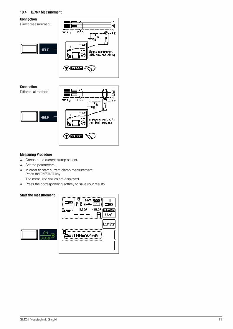
GMC-I Messtechnik GmbH 71
18.4 IL/AMP Measurement
Connection Direct measurement
Connection Differential method
Measuring Procedure➭ Connect the current clamp sensor.➭ Set the parameters.➭ In order to start current clamp measurement:
Press the ON/START key.– The measured values are displayed.➭ Press the corresponding softkey to save your results.
Start the measurement.

72 GMC-I Messtechnik GmbH
19 T %r.H. – Measurement of Temperature and Atmospheric Humidity
Select the measuring function:
19.1 GeneralTemperature and relative atmospheric humidity can be measured with the Z506G accessory sensor with the help of this measuring function.
19.2 Help FunctionIllustrations and measurement instructions can be displayed by pressing the HELP key.The help function is exited by pressing the ESC key.
19.3 ParametersTemperature can be displayed in either °C or °F by pressing the corresponding softkey.
19.4 T % r.h. Measurement
ConnectionThe sensor is connected to socket 5: RS 232 port.
Measuring Procedure➭ Connect the Z506G T/F sensor.– The measured values are displayed.➭ Press the corresponding softkey to save your results.
Save the measured value.
The following measured values are displayed:– ϑ: temperature [°C/°F]– r.H.: relative humidity [%]
The following points must be observed:– Automatic test instrument shutdown is not active in this func-
tion.– The RS 232 port is not intended for communication with the
PC.– Monitoring of the probes’ measurement inputs is not active for
the basic measuring functions (probes for 1(L), 2(N) and 3(PE) or L1, L2 and L3) with this measuring function. Simultaneous voltage measurement or checking for the absence of voltage is not possible in this function.
T % r.h.

GMC-I Messtechnik GmbH 73
20 Extra – Special Functions
Select the EXTRA switch position.
Overview of Special Functions
Selecting Special FunctionsThe list of special functions is accessed by pressing the upper-most softkey. Select the desired function with the appropriate icon.
Example: Selecting the PRCD Test
Softkey Meaning / Special Function Section / Page
Voltage drop measurement
Function ΔU
section 20.1 on page 74
Documentation of charging station tests (checking the operating states of an electric vehicle at charging stations per IEC 61851)
section 20.2 on page 76
Documentation of fault simulations at PRCDs with the PROFITEST PRCD adapter
section 20.3 on page 77
Extra
1
2
2
3
4
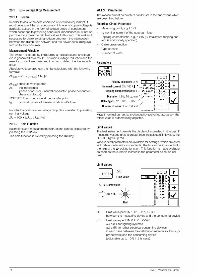
74 GMC-I Messtechnik GmbH
20.1 ΔU – Voltage Drop Measurement
20.1.1 GeneralIn order to assure smooth operation of electrical equipment, it must be assured that an adequately high level of supply voltage is available. Losses in the form of voltage drops at conductors which occur due to prevailing conductor impedances must not be permitted to exceed certain limit values to this end. This makes it necessary to check existing voltage drop from the intersection between the distribution network and the power consuming sys-tem up to the consumer.
Measurement PrincipleThe system is loaded by introducing a resistance and a voltage dip is generated as a result. This mains voltage reduction and the resulting current are measured in order to determine line imped-ance.Absolute voltage drop can then be calculated with the following formula:ΔUabs = (Z – ZOFFSET) • IN, [V]
ΔUabs: absolute voltage dropZI: line impedance
(phase conductor – neutral conductor, phase conductor – phase conductor)
ZOFFSET: line impedance at the transfer pointIN: nominal current of the electrical circuit’s fuse
In order to obtain relative voltage drop, this is related to prevailing nominal voltage:ΔU = 100 • ΔUabs / UN, [%]
20.1.2 Help FunctionIllustrations and measurement instructions can be displayed by pressing the HELP key.The help function is exited by pressing the ESC key.
20.1.3 ParametersThe measurement parameters can be set in the submenus which are described below:
Electrical Circuit Parameter– Measuring point, e.g. L1-N– IN: nominal current of the upstream fuse– Tripping characteristic, e.g. 5 x IN (B) (maximum tripping cur-
rent is additionally specified)– Cable cross-section– Type of cable– Number of wires
Parameters
Note: If nominal current IN is changed by prevailing ΔUOFFSET, the offset value is automatically adjusted.
Limit ValuesThe test instrument permits the display of exceeded limit values. If measured voltage drop is greater than the selected limit value, the UL/R LED lights up red.Various fixed parameters are available for settings, which are cited with reference to various standards. The list can be extended with the help of the editing function. This function is made available as soon as the cursor is located in the parameter selection col-umn.
Limit Values
DIN Limit value per DIN 18015-1: ΔU < 3% between the measuring device and the consuming device
VDE Limit value per DIN VDE 0100-520: ΔU ≤ 3% for lighting systems ΔU ≤ 5% for other electrical consuming devices in each case between the distribution network (public sup-ply network) and the consuming device (adjustable up to 10% in this case)
Nominal current: 2 to 160 A
Polarity selection: Lx-N
Diameter: 1.5 to 70 sq. mm
Cable types: NY..., H03... - H07...
Number of wires: 2 to 10 strand
Tripping characteristics: B, L
Limit value:
ΔU % > limit value
UL / RL
ΔU
Red

GMC-I Messtechnik GmbH 75
20.1.4 ZOFFSET Measurement
GeneralThe ZOFFSET function offers the option of saving the line imped-ance of the transfer point as an offset value and taking it into account for subsequent voltage drop measurements.
Connection
Probe 1(L)Probe 3(PE)
Measuring Procedure➭ Activate the ZOFFSET function by pressing the corresponding
softkey.
– The following values are displayed: “ΔUOFFSET 0.00% ZOFFSET 0.00 Ω“
➭ Connect the test probes to the transfer point (measuring de-vice / meter).
➭ Start measurement by pressing the IΔN key.First of all, an intermittent acoustic warning is generated and a blinking message appears, in order to prevent inadvertent deletion of a pre-viously saved offset value. ➭ Start offset measurement by pressing
the triggering key once again or abort offset measurement by pressing the▼ ON/START key (in this case ESC).
– ZOFFSET is measured and ΔUOFFSET is calculated.
– The values are displayed.
The following points must be observed:– If nominal current IN changes, ΔUOFFSET is adjusted auto-
matically.– The ascertained ZOFFSET value is deleted when the function
is deactivated.– If an error message appears, the last acquired, valid value is
retained.– As a result of the utilized 4-wire technology, resistance of the
probe cables does not have to be calculated into the mea-surement results.
20.1.5 ΔU MeasurementConnection
Probe 1(L)Probe 3(PE)
Measuring Procedure➭ Connect the test probes.➭ Set the parameters.➭ In order to start the voltage drop measurement:
Press the ON/START key.➭ If measurement has to be aborted:
Press ON/START or ESC.– Measurement is performed.– The measured values are displayed.➭ Press the corresponding softkey to save your results.
Start measurement with OFFSET.
The following measured values are displayed:– ΔU: relative voltage drop– Z: line impedance– U: momentary voltage at the test probes,
“UN” is displayed if voltage U max. deviates from nominal voltage by 10%
– f: frequency of the applied voltage, “fN” is displayed if frequency f max. deviates from nominal frequency by 1%
With activated ZOFFSET function:– ΔUOFFSET: relative voltage drop at the transfer point– ZOFFSET: line impedance at the transfer point
1
1
2
2

76 GMC-I Messtechnik GmbH
20.2 E-Mobility – Checking the Operating States of an Electric Vehicle at Charging Stations per IEC 61851
A charging station is a facility designed to charge electric vehi-cles in accordance with IEC 61851, and is equipped with essential elements including a plug connector, conductor protec-tion, an RCD, a circuit breaker and a safety communication device (PWM). Depending on where it’s used, other function modules may be added, for example for mains connection and metering. An inspection of the charging sta-tion is performed with the PRO-TYPII (Z525A) test adapter.
Selecting the Adapter (test box)
After selecting charging station in the EXTRA menu, the adapter can be chosen by pressing the charging station symbol in the upper right-hand corner. The EXTRA selection menu is accessed by pressing this key once again.
Simulation of Operating Statuses per IEC 61851 with theMENNEKES Test Box (statuses A through E)The MENNEKES test box is used exclusively to simulate the vari-ous operating statuses of a fictitious electric vehicle connected to a charging station. Settings for the simulated operating statuses can be found in the operating instructions for the test box.The simulated operating statuses can be saved to the test instru-ment as a visual inspection and documented in the report generat-ing program.Select the respective status to be checked with the SECLECT STATUS key at the test instrument.
Status A – charging cable connected to charging point only• CP signal is activated • Voltage between PE and
CP is 12 V
Status B – charging cable connected to charging point and vehicle• Charging cable is locked
into place at the charging point and the vehicle
• Vehicle is not yet ready for charging
• Voltage between PE and CP: +9 V / -12 V
Status C – non-gassing vehicle detected• Vehicle is ready for charging
/ power is connected • Voltage between PE and
CP: +6 V / -12 V
Status D – gassing vehicle detected• Vehicle is ready for charging
/ power is connected • Voltage between PE and
CP: +3 V / -12 V
Status E – cable is damaged• Short-circuit between PE
and CP • Charging cable is unlocked
at the charging point• Voltage between PE and
CP is +0 V
Semi-Automatic Changing of Operating StatusesAs an alternative to manual sta-tus changing via the parame-ters menu for the SECLECT STATUS softkey at the test instrument, quick and con-venient switching amongst the statuses is also possible. The AUTO status parameter has to be selected to this end. After responding to the visual inspection prompt and saving the results, automatic switching to the next status ensues – the 01/05 key display corresponds to A/E (01 = A, 02 = B, 03 = C, 04 = D, 05 = E). Given statuses can be skipped by pressing the IΔN key at the test instrument or the corresponding key on the optional I-SK4/12 probe.
PRO-TYPII (Z525A)

GMC-I Messtechnik GmbH 77
20.3 PRCD – Test Sequences for Documenting Fault Simulations at PRCDs with the PROFITEST PRCD Adapter
The following functions are possible after connecting the test instrument to the PROFITEST PRCD test adapter:• There are three preset test sequences:
– PRCD-S (single-phase / 3-pole)– PRCD-K (single-phase / 3-pole)– PRCD-S (3-phase / 5-pole)
• The test instrument runs through all test steps semi-automati-cally: Single-phase PRCDs: – PRCD-S: 11 test steps – PRCD-K: 4 test steps 3-phase PRCDs: – PRCD-S: 18 test steps
• Each test step is evaluated and assessed by the user (go/no-go) for later documentation.
• Measurement of the PRCD’s protective conductor resistance using the test instrument’s RLO function. Please note that the protective conductor measurement is a modified RLO mea-surement with ramp sequence for PRCDs (see section 10.1.7).
• Measurement of the PRCD’s insulation resistance using the test instrument’s RISO function (see section 11).
• Tripping test with nominal residual current using the test instrument’s IF function (see section 12.3).
• Measurement of time to trip using the test instrument’s IΔN function (see section 12.4).
• Varistor test with PRCD-K: measurement via ISO ramp (see section 11.2).
Attention!!Before connecting the PROFITEST PRIME to the PRCD adapter, be sure to read the operating instructions for the PROFITEST PRCD.
20.3.1 Selecting the PRCD to be Tested
After selecting PRCD in the EXTRA menu, the desired adapter can be chosen by pressing the adapter symbol in the upper right-hand area. The EXTRA selection menu is accessed by pressing this key once again.
20.3.2 Parameter Settings
Meanings of Symbols for the Respective Fault Simulations
PRCD-S Single-Phase Parameter – Parameter 11 = 11 Test StepsTogether with the required intermediate steps for PRCD activation (= ON) the parameters for fault simulations represent the 11 pos-sible test steps: Interrupt (BREAK...), reversed conductors (L1 <-> PE), PE to phase (Uext -> PE), contact with the ON key, protective conductor current measurement (figure below: PRCD-Ip).
PRCD-S 3-Phase Parameter – Parameter 18 = 18 Test Steps
PRCD-K Single-Phase Parameter – Parameter 4 = 4 Test Steps
Switch PositionPROFIT-EST PRCD
Symbol at PROFITEST PRIME
Significance of Symbol
Parameter Setting.
Menu Display
ON 1~ON Single-phase PRCD activated
ON 3~ON 3-phase PRCD activated
BREAK Lx Interrupted phase
Lx <-> PELx <-> N
Wires reversed between phase con-ductor and PE or neutral conductor
PE-UEXT Uext -> PE PE to phase
PROBE Contact the ON key at the PRCD with the probe
PRCD-Ip Protective conductor current measurement with current clamp transformer
— AUTO AUTO Semi-automatic change of fault simulations

78 GMC-I Messtechnik GmbH
20.3.3 PRCD-S Test Sequence (single-phase) – 11 Test Steps
Selection Examples
Simulation of Interruption (steps 1 to 6)
Reversed Conductor Simulation (step 7)
Simulation of PE to Phase (step 8)
Contact ON Key at PRCD with Probe (step 10)
Measurement of Protective Conductor Current with a Current Clamp Transformer (step 11)
20.3.4 PRCD-S Test Sequence (3-phase) – 18 Test Steps
Selection Examples
Simulation of Interruption (steps 1 to 10)
Reversed Conductor Simulation (steps 11 to 16)
Simulation of PE to Phase (step 17)
Measurement of Protective Conductor Current with a Current Clamp Transformer (step 18)
Semi-Automatic Changing of Operating StatusesAs an alternative to manual sta-tus changing via the parameters menu at the test instrument, quick and convenient switching amongst the fault simulations is also possible. The AUTO status parameter has to be selected to this end. After responding to the visual inspection prompt and saving the results, automatic switching to the next fault simu-lation ensues. Given fault simulations can be skipped by pressing the IΔN key at the test instrument or the corresponding key on the optional I-SK4/12 probe.

GMC-I Messtechnik GmbH 79
21 HV AC – Testing for Dielectric Strength (with PROFITEST PRIME AC)
Select the measuring function:
Caution: High-Voltage!It’s absolutely essential to observe the safety precautions in section 3.1 and section 3.2, as well as the checklist on page 13.
21.1 GeneralThe electrical equipment of the machine under test must with-stand a test voltage of twice its own rated voltage value or 1000 V~ (whichever is largest) applied between the conductors of all circuits and the protective conductor system for a period of at least 1 second. The test voltage must have the same frequency as the electrical supply network, and must be generated by a transformer with a minimum power rating of 500 VA. The stan-dard sequence, continuous operation and pulse control modes are available for various testing tasks.
Attention!!The test instrument itself must not be used as a device under test when testing for dielectric strength with HV AC.
Attention!!Before beginning work, the test instrument, the high volt-age cables, the high-voltage pistols and accessories must be inspected to assure that they are in flawless condition (see also section 3.2 on page 13).
Attention!!Warning lamps (Z506B signal lamp combination) may possibly fail (for example due to damaged lamp inserts or connector cables). Therefore, the inspector always has to ensure that no other persons are present in the potential danger zone of the test to be performed or of the DUT (e. g. by means of appropriate shutoff measures).
Attention!!Monitoring the Measurement Inputs Monitoring of the probes’ measurement inputs is not ac-tive for the basic measuring functions (probes for 1(L), 2(N) and 3(PE) or L1, L2 and L3) with the HV AC measur-ing function for testing dielectric strength. Simultaneous voltage measurement or checking for the absence of voltage is not possible in this function. Before conducting the high-voltage test, make sure that the electrical circuit to be tested or the respective system components are voltage-free (measuring function U – measuring voltage and frequency, see section 9)!
NoteChecking the Measurement Cables If measurement isn’t started with the high-voltage mod-ule in the standby state (test instrument ready for activa-tion, red signal lamp lit up) although both high-voltage pistols have been activated, one of the measurement cables is probably interrupted.
Measurement PrincipleTesting for dielectric strength is conducted by outputting an alter-nating voltage of 200 V to 2.5 kV at line frequency (primarily sinu-soidal oscillation with a frequency of 45 to 65 Hz). In accordance with DIN EN 61439-1, test current is at least 100 mA, and short-circuit current which must be supplied by the high-voltage trans-former (at least 500 VA nominal power) is 200 mA.In order to protect the device under test, current limiting and rise time until the selected test voltage is reached can be selected.In the event of short-circuiting or breakdown due to an insulation defect at the device under test, measurement is stopped when the selected shutdown current has been reached and achieved test voltage is displayed.
The following operating modes can be selected:– Standard sequence for standards-compliant testing for
dielectric strength– Continuous operation for long-term testing and troubleshoot-
ing– Pulse control mode for troubleshooting
ApplicationsThe high-voltage module for the PROFITEST PRIME AC is intended for quick and safe performance of testing for dielectric strength at electrical and electronic equipment and systems in machines in accordance with DIN VDE 0113/EN 60204-1.All of the values required for approval reports can be measured with this instrument.
21.1.1 Help FunctionIllustrations and measurement instructions can be displayed by pressing the HELP key.The help function is exited by pressing the ESC key.
21.2 ConnectionSee section 5.2 on page 17 regarding connection of the signal lamp combination, the emergency off switch and the high-voltage pistols.
Optical Indication – HV TEST LEDWhen lit up, the red caution LED above the key switch indicates that the HV switch position has been selected and that the HV TEST connector panel is active, and that HV test voltage is applied to the sockets for the high-voltage pistols.– Continuous illumination: Ready for operation and for activation– Blinking: Active testing, high-voltage is present
Attention!!Detection of interference voltage at probes 1(L), 2(N) and (PE) is not possible in the HV switch position.
Optical Indication – SIGNAL PROFITEST PRIME ACThe signal lamp combination which has to be connected (acces-sory: Z506B) indicates the following states:– Green: no high voltage present, LCD: – Red: high voltage ready, danger! LCD:
Acoustic Indication – Periodic Acoustic WarningAcoustic signaling takes place during the test sequence – when high-voltage is present. The repetitive acoustic sequence is higher pitched in the pulse control mode than during the other two volt-age sequences.
HV
0 t [s]0.5 1 1.5
Test in progress
Repetitive sequence

80 GMC-I Messtechnik GmbH
21.3 ParametersThe desired voltage sequence is entered here, followed by the respective parameters.
Standard Sequence
After selected rise time t has elapsed, specified U is applied until the selected test duration ton has elapsed.Shutdown current ILIM can be adjusted within a range of 1 to 200 mA. If this value is exceeded, test voltage is switched off within 0.5 ms.
Continuous Operation
After selected rise time t has elapsed, specified U is applied until the triggers at the high-voltage pistols are released.Continuous operation “>>>” is set as test duration ton.Shutdown current ILIM can be adjusted within a range of 1 to 200 mA. If this value is exceeded, test voltage is switched off within 0.5 ms.
Pulse Control Mode
We recommend selecting the pulse control mode for trouble-shooting purposes (arc-over location).Continuous operation “>>>” is set as test duration ton.Shutdown current ILIM is permanently set to roughly 125 mA in the pulse control mode. If this value is exceeded, test voltage is switched off within 0.5 ms. After approximately 0.6 seconds, test voltage is cyclically increased from 0 V to the selected final value within a period of t = 0.2 s, or is switched back when shutdown current is reached.
Test voltage U: Test voltage level Entry limits: 200 V ... 2500 V
Rise time t : Time during which test voltage is increased to the selected value Entry limits: 0.1 s ... 99.9 s (does not apply to pulse control mode which has a fixed setting of 0.2 s)
Test duration ton: Time during which test voltage is applied Entry limits: 1 s ... 120 s (does not apply to the continuous operation function or the pulse control mode for which continuous measurement “ton >>>” is selected)
ILIM: Max. permissible current before high-voltage is switched off Entry limits: 1 ... 200 mA (does not apply to pulse control mode)
A list of all entry limits and default values is included in the section 25.
2-Pole Measurement with Fast and Semiautomatic Polarity Reversal
For details on fast or semiautomatic polarity reversal refer to sec-tion 8.6.
Standard sequenceContinuous operation
Voltage sequence
Pulse control mode
Testvoltage
Rise Test duration ton Fall*Test time
Time
* Constant = 0.1 s
U
Testvoltage
Rise Test duration tonTest time
Time
U
PauseRise
U
t0.6 s0.2 s
Testvoltage
Test durationRise time
Test voltage
Example: (maximum) preset-ting for the standard sequence
Maximum current

GMC-I Messtechnik GmbH 81
21.4 Function Test (test preparation)Execute the following function test in the specified order.➭ Make sure that the test instrument is connected to mains sup-
ply power and that the mains switch is set to ON. Testing for dielectric strength is not possible during battery operation.
Testing the Key Switch and Indicating DevicesAn automatic self-test of the signal lamps is performed whenever rotary switch position HV has been selected and the voltage test has been launched for the first time, see section 6.➭ Set the key switch to the “symbolic padlock closed” position.– The HV TEST LED lights up if the rotary selector switch is in
the HV position.– Neither the green nor the red sig-
nal lamp may light up.– The symbols SIGNAL (for the sig-
nal lamp combination), OFF (for the emergency off switch) and KEY (for the key switch) are grayed out in the footer of the LCD.
➭ Set the key switch to the “symbolic padlock open” position.– The HV TEST LED lights up if the rotary selector switch is in
the HV position.– The green signal lamps must
light up.– LCD: – The symbols SIGNAL (for the sig-
nal lamp combination), OFF (for the emergency off switch) and KEY (for the key switch) must appear fully black in the footer of the LCD.
ErrorIn the event that one of the symbols is grayed out, the signal lamp combination or the emergency off switch is not connected, the emergency off switch is activated or the key switch is not set to the “open” position. A defective signal lamp combination or emer-gency off switch, or faulty mains power supply, also cause gray-ing out of the respective symbol.In this case the test instrument is not ready for activation.If the ON/START key is pressed in this case, the following error message appears:
NoteThe emergency off switch, the signal lamp combination and mains supply power are continuously monitored during operation. Activation of the emergency off switch, defective safety devices or faulty mains supply power result in immediate shutdown of the high-voltage module or prevent the test from being started. Further internal protective measures (e.g. temperature monitoring) continuously ensure the safety of the user as well. and protect the instrument against damage.
Starting the Voltage Test (test run)
Attention!!Only start testing for the absence of voltage in the case of correct indication by means of the connected indicat-ing device for HV operation. Observe the safety precau-tions in section 3.2 on page 13.
After Pressing the ON/START Key– The red signal lamp must light up, LCD: .– The high-voltage pistols appear at the display and the PRESS
message prompts the user to activate them.– The symbol shown at the right is mirrored from left to
right and vice versa until the measurement is started by activating the high-voltage pistols.
Caution: High-Voltage!Touch neither the test probes nor the device under test during the test for dielectric strength! Life endangering high-voltage of up to 2.5 kV is present at the test probes of the high-voltage pistols!
➭ Pull the triggers of the high-voltage pis-tols to the limit stop and hold.
During Voltage Test– The RUN symbol shown at the right is continuously
active.– The HV TEST LED blinks.– The two high-voltage warning symbols appear at the display
and alternate back and forth between normal and inverse dis-play.
– A periodic acoustic warning accompanies the measurement.– Momentary test voltage U is displayed.– The current position within the voltage sequence is indicated
by the filled trapezoid.
➭ Release the triggers at the high-voltage pistols.No later than after selected test duration ton, test voltage is switched off automatically.

82 GMC-I Messtechnik GmbH
Testing the Shutdown Function(voltage/standard sequence mode only)➭ Pull the triggers of the high-voltage pistols to the limit stop and
hold.➭ During measurement: briefly short circuit the high-voltage pis-
tols.– The instrument is shut down immediately.– The green signal lamp must light up and red may not light up.– The following values appear at the LCD:
U : – – – I : – – –
21.5 Test Sequence
Attention!!Before starting the test, make sure that – The measurement cables are fully extended – All access to the danger zone is closed and all
persons have exited the danger zone before the testing systems is rendered ready for activation
➭ Set the key switch to the “symbolic padlock open” position.The test instrument is switched to the “standby” mode. The green signal lamp lights up.➭ Check the test parameters.➭ Press the ON/START key.The test instrument is switched from the “standby” mode to “ready for activation”. The red signal lamp lights up, LCD: .
Caution: High-Voltage!Touch neither the test probes nor the device under test during the test for dielectric strength! Life endangering high-voltage of up to 2.5 kV is present at the test probes of the high-voltage pistols!
➭ Position the high-voltage pistols in close proximity to the de-vice under test.
➭ Pull the triggers of both high-voltage pistols, but only up to the point of mechanical resistance at which the test probes are exposed.
➭ Establish contact with the electrical circuits.➭ Pull the triggers of the high pistols to the limit stop.– High-voltage is now switched to the test probes.– Testing continues until the selected rise time and the test
duration have elapsed, or until the triggers are released in the case of measurement with ramp function.
– Test time (application of high-voltage from rise to drop-off) is indicated acoustically and optically by the blinking LED at the test instrument.
➭ For subsequent testing of neighboring circuits release the trig-gers, establish contact with the next circuit and pull the trigger to the limit stop once again. The test is started anew. If breakdown occurs during testing or if the selected shut-down current is not reached, the test must be restarted.
NoteIf the next measurement is not started within 30 seconds, the system is switched from ready for activation to the standby mode – the signal lamp combination changes from red to green and measurement must be restarted (safety shutdown).
Test EvaluationSuccessful or unsuccessful high-voltage testing is indicated by means of a corresponding pop-up and a brief acoustic signal.
Test passed:The test object has withstood testing for dielectric strength in compliance with the selected parameters for nominal test voltage, test duration and maximum current in the standard sequence operating mode.
The tested system segment or test object fulfills requirements in accordance with DIN VDE 0113 / EN 60204-1 / IEC 204-1.The following pop-up appears at the display and a brief, high-pitched acoustic signal is generated:
In the case of successful testing (test passed), the device remains in the "ready for activation" state - the red signal lamp remains lit up, LCD:
The test can be repeated or further testing of dielectric strength can be conducted with the previously selected parameters by once again pulling the triggers of the high-voltage pistols. The pop-up is automatically cleared when the triggers are pulled.
The test is restarted using the same sequence, including the same ramp-up as before. Indication takes place in the same way as well.
The "PASS" pop-up must be cleared by pressing the ESC key in order to view the measured values or save them to the database.The measured values then become visible and the memory key for saving them is enabled..
After saving the measured values, the device is auto-matically switched back to the "ready for activation" state - the red signal lamp goes out and the green signal lamp lights up once again, LCD:
In order to conduct further testing or a new test, testing has to be started again by pressing the ON/START key. If applicable, the parameters must first be adjusted.

GMC-I Messtechnik GmbH 83
Test failed:The test object has not withstood testing for dielectric strength in compliance with the selected parameters for nominal test voltage, test duration and maximum current in the standard sequence operating mode. The limit value has been violated for at least one of the parameters. If the test has been performed in continuous operation mode, the maximum current has been exceeded and/or a breakdown has been detected.– Maximum current exceeded / breakdown– Test duration not complied with– Nominal voltage fallen short of
The tested system segment or test object does not fulfill require-ments in accordance with DIN VDE 0113 / EN 60204-1 / IEC 204-1.The following "FAIL" pop-up appears at the display and a brief, low-pitched acoustic signal is generated:
In the event that testing is failed, the device is automatically switched back to the "ready for activation" state - the red signal lamp goes out and the green signal lamp lights up once again,LCD:
In order to conduct further testing or a new test, testing has to be started again by pressing the ON/START key. If applicable, the parameters must first be adjusted.
Saving Measured ValuesAfter the test sequence has been completed (complete testing with "pass" or "fail" test results), the last acquired measured val-ues for Umax, I and ϕ are retained at the display. The correspond-ing pop-up with the test results must first of all be cleared to this by pressing the ESC key.If testing has been ended with meaningful test results, the current measured values can be saved to the data-base with the save key. The measured values at the display are overwritten when the next test is executed.
Premature Abortion of the TestThe test can be ended prematurely at any time:– By pressing the emergency off switch– By turning the key switch to the “symbolic padlock closed” position– By Pressing the ON/START Key– By interrupting mains supply power
NoteBreakdown VoltageIf shutdown current ILIM is exceeded before the selected test voltage has been reached, test voltage U and current ILIM measured at this point in time appear at the display and are saved to memory.
Standby OperationBy releasing the trigger of either high-voltage pistol – high voltage is no longer present – the high-voltage testing module switches into the „ready for operation“ mode. A further test is enabled by pressing the two pistols once more. The „ready for operation“ mode is retained for a period of 30 seconds (user-inactivity-time-out). If no pistol is operated during this period, the test is aborted after 30 seconds.
21.5.1 Ending the Test for Dielectric Strength➭ Release one or both high-voltage pistols. High voltage is no
longer applied. The high-voltage testing module switches into the „ready for operation“ mode, see also chapter "Standby Operation".
➭ Press the ON/START key in order to end the test, if it hasn’t al-ready been ended automatically (breakdown or shutdown current reached, green signal lamp already lit up).
➭ The display at the signal lamp combination changes from red to green, LCD: .
➭ The test system must be removed from service (signal lamps off) if left unattended. Set the key switch to the “symbolic padlock closed” position to this end.
➭ Set the key switch to the “symbolic padlock closed” position and remove the key, and secure the device against unauthorized use.
21.5.2 Setting Ranges for Parameters and Standard Values per DIN VDE
* Recommended** The respectively larger value must be used.
Parameter Lower Limit Standard Value
Upper Limit Special Setting
Test duration 0.5 s 1 s 120 s Continuous mea-surement
Test voltage 200 V 1 kV or 2 x UN**
2.5 kV
Shutdown current IMAX
0.2 mA — 200 mA Pulse control mode
Rise time 100 ms 1 s * 99.9 s

84 GMC-I Messtechnik GmbH
22 AUTO – Test Sequences (automatic test sequences)
Select the measuring function:
With the rotary switch in the AUTO position, all of the test sequences in the device are displayed.
22.1 General
Layout of the Test SequencesIf the same sequence of tests will be run frequently (one after the other with subsequent report generation), for example as speci-fied in the standards, it’s advisable to make use of test sequences.Automated test sequences can be compiled from manually cre-ated individual measurements with the help of the test sequence function. A test sequence consists of up to 200 individual steps, which are executed one after the other. Fundamentally, differentiation is made amongst three types of individual steps:• Note (“visual Inspection” test step): Test sequences are inter-
rupted when a pop-up message is displayed for the inspector. The test sequence is not resumed until the messages has been acknowledged. Sample message before insulation resistance measurement: “Disconnect the device from the mains!”
• Visual inspection, testing and report generation: The test sequence is interrupted when a passed/failed evaluation is displayed. The comment and the results of the evaluation are saved to the database.
• Measurement (“user-evaluated measurement” test step): same as individual measurements with the instruments with storage and parameters configuration
Creating Test Sequences with IZYTRONIQAs of firmware version 1.2.0, test sequences are created at a PC with the help of the included IZYTRONIQ software, and are then transferred to test instrument. Any number of test sequences can be created and stored at the PC in IZYTRONIQ. Up to 10 selected test sequences can be transferred to the test instrument.No option for transferring test sequences from the test instrument back to the PC has been provided for because sequences can only be created, managed and stored at a PC.General instructions regarding the creation of test sequences can be found in the online help provided with IZYTRONIQ.
22.2 Creating and Transferring Test Sequences with IZYTRONIQ (step-by-step instructions)
➭ Select “Stationary Objects” .➭ Then select the “Sequences” menu .➭ Click the “Add” symbol . The “Create New Sequence” field
is displayed. Enter a “Sequence Name”, a “Test Type” and a “Standard”, and select your currently connected instrument under “For Device”. Acknowledge by clicking “Add”.
➭ Save the settings by clicking the icon.➭ Select the new entry and then the sequence editor . The
editing menu appears with “Step Selection” and “Design Progress”.
➭ Select the test instrument which is displayed in “Step Selec-tion”. “Visual Inspection” and “User-Evaluated Measurement” appear.
➭ “Test Step: Visual Inspection” is opened in the bottom left-hand window by dragging “Visual Inspection” into the “Design Progress” field. The parameters or details for the respective test step must be entered here.
➭ Save the settings by clicking the icon.➭ “Test Step: User-Evaluated Measurement” is opened in the
bottom left-hand window by dragging “User-Evaluated Mea-surement” into the “Design Progress” field. The parameters or details for the respective test step must be entered here.
➭ Save your settings.➭ Repeat the test steps until the test sequence is finished.➭ Save your settings by clicking the icon.➭ Select “Stationary Objects” again .➭ Then select the “Export” function . The export wizard ap-
pears. ➭ Select the desired test instrument and insert a checkmark
next to “Sequences”. Select “Export”. The “Export Sequences (max. 10)” menu appears.
➭ Mark the sequences to be exported and click the “Export to Test Instrument” icon .
For as long as the test sequences are being transferred, a progress bar is displayed at the PC and the illustration shown to the right appears at the test instrument’s display.
Successful transfer to the test instrument via IZYTRONIQ is then indicated at the PC.
NoteAll test sequences previously stored at the test instru-ment are deleted. Only those test sequences transferred during the most recent export operation via IZYTRONIQ are saved at the test instrument.
Auto

GMC-I Messtechnik GmbH 85
Please note that test sequences which have been loaded to the test instrument are deleted when:• New test sequences are received from the PC• The test instrument is reset to its default settings
(SETUP switch position → GOME SETTING key)• The firmware is updated• The user interface language is changed
(SETUP switch position → CULTURE key)• The test instrument’s entire database is deleted
Configuring Test Sequence ParametersMeasurement parameters are also configured at the PC. How-ever, parameters can be changed at the test instrument during the test sequence before the respective measurement is started.When the test step is started once more, the parameter settings specified in IZYTRONIQ are loaded again.
NoteIZYTRONIQ does not subject the parameters to a plausibil-ity check. As a result, the newly created test sequence should be checked at the test instrument before it’s per-manently added to the database.
Limit values are not currently set in IZYTRONIQ, and have to be adjusted during the automatic test sequence.
Selecting and Starting a Test Sequence at the Test InstrumentFig. 22.3
The selected test sequence (SEQU.1 in this case) is started with the ON/START key.When a measurements type test step is executed, the same screen layout appears as is also the case for individual measure-ments. The current test step number (in this case step 01 of 06) appears in the header instead of the memory and battery symbols (see Fig. 22.4). After pressing the “Save” key twice, the next test step is displayed.
Setting Parameters and Limit ValuesParameters and limit values can also be changed while a test sequence is running or before the respective measurement is started. The respective change only affects the active test sequence and is not saved.
Skipping Test StepsThere are two ways to skip test steps or individual measurements:• Select the test sequence, change to the test step column at
the right with the help of the cursor, select the xth test step and press the ON/START key.
• The navigation menu can be opened within the test sequence by pressing the navigation key (cursor left-right). Jumping to the next or the previous test step is possible using the separate scroll keys which then appear. The navigation menu can be exited again and the current test step can be displayed by pressing the ESC key.
Aborting or Ending a Test SequenceAn active sequence can be aborted by pressing the ESC key and then acknowledging.“Sequence Ended” appears after the last test step is completed. After acknowledging the prompt, the initial menu, “List of Test Sequences”, is once again displayed.
Fig. 22.4

86 GMC-I Messtechnik GmbH
23 Database
23.1 Creating Distributor Structures, GeneralA complete distributor structure with data for electrical circuits and RCDs can be created in the PROFITEST PRIME test instrument. This structure makes it possible to assign measurements to the electrical circuits of various distributors, buildings and customers.
There are two possible procedures:• On location or at the
construction site: create the distribu-tor structure in the test instrument. A distributor struc-ture with up to 30,000 structure ele-ments can be cre-ated in the test instrument, which is saved to the instru-ment’s flash mem-ory.
or
• Create and save an existing distributor structure with the help of the report generating program IZYTRONIQ.
Notes concerning IZYTRONIQRead the online help for the PC program regarding installation and use.
23.2 Transferring Distributor StructuresThe following data transfer operations are possible:• Transfer a distributor structure from the PC to the test instru-
ment.• Transfer a distributor structure including measured values
from the test instrument to the PC.
The test instrument and the PC must be con-nected with a USB cable in order to transfer struc-tures and data.
The following image appears at the display during transfer of struc-tures and data.
23.3 Creating a Distributor Structure in the Test Instrument
Overview of the Meanings of Icons used to Create StructuresSymbol MeaningMain Level
Sub-Level
Memory menu, page 1 of 3Cursor UP: scroll up
Cursor DOWN: scroll down
ENTER: acknowledge selection+ → – change to sub-level
(open directory) or – → + change to main level
(close directory) Display the complete structure designation (max. 63 characters) or ID number (25 characters) in a zoom windowTemporarily switch back and forth between structure designation and ID number. These keys don’t have any effect on the main setting in the setup menu (see “DB Mode” on page 22). Hide the zoom window
Change display to menu selection

GMC-I Messtechnik GmbH 87
Memory menu, page 2 of 3Add a structure element
Selection: UP/DOWN scroll keys and ↵In order to add a designation to the selected structure element, refer to the edit menu in follow-ing column.
Test in-stru-ment
IZY-TRO-NIQ
Location TreeProperty
Building
Floor
Room
E-Tree (electrical tree)Customer
Electrical system
Machine
Distributor
Circuit
RCD
RCM
RCBO
IMD
Operating equipment
Equipotential bonding busbar
Equipotential bonding conductor
Earth electrode
Measuring point
Symbol MeaningEDIT For additional icons see edit menu below
Delete the selected structure element.
Show measurement data, if a measurement has been performed for this structure element.
Edit the selected structure element.
Memory menu, page 3 of 3Search for ID number.> Enter complete ID number.
Search for text.> Enter full text (complete word).
Search for ID number or text.
Continue searching.
Edit menuCursor LEFT: Select an alphanumeric character.
Cursor RIGHT: Select an alphanumeric character.
ENTER: Accept an individual character.
←→
Acknowledge entry.
Scroll left.Scroll right.Delete characters.
Switching amongst different types of alphanu-meric characters:
A Upper case letters
a Lower case letters
0 Numbers
@ Special characters
Symbol Meaning

88 GMC-I Messtechnik GmbH
Distributor Structure Symbology / Tree Structure
23.3.1 Creating Structures (example for electrical circuit)After selection with the MEM key, all setting options for the cre-ation of a tree structure are made available on three menu pages (1/3, 2/3 and 3/3). The tree structure consists of structure ele-ments, referred to below as objects.
Selecting the Position at which a New Object will be Added
Use the ↑↓ keys in order to select structure elements.Change to the sub-level with the ↵ key.Go to the next page with the >> key
Creating a New Object
Press the key in order to create a new object.
Selecting a New Object from a List
Select the desired object from the list with the ↑↓ keys and acknowledge with the ↵ key.
Entering a Designation
Enter a designation and then acknowledge it by pressing ✓.
NoteAcknowledge the standard or adjusted parameters shown below, because the created designation will oth-erwise not be accepted and saved.
Setting Electrical Circuit Parameters
For example, nominal current values must be entered here for the selected electrical circuit. Measuring parameters which have been accepted and saved in this way are subsequently accepted by the current measuring menu automatically when the display is switched from the structure view to measurement.
NoteElectrical circuit parameters changed during structure creation are also retained for individual measurements (measurement without saving data).If you change the electrical circuit parameters specified by the structure in the test instrument, a warning is displayed when the change is saved.
Distributor
A check mark to the right of a structure element means that all measurements within the respective hierarchy have been passed.x: At least one measurement has not been passed.No symbol: Measurement has not yet been performed.
System Customer
RCD Circuit
Equipment
Same type of element as in the Windows Explorer:+: sub-objects available, display by pressing ↵.–: sub-objects are displayed, hide by pressing ↵.
Equipment
Scroll up
Scroll down
Acknowledge selection /
Display object
Next page
change level
or ID number
Create object
Delete object
VΩA: show measurement data
Edit designation
Scroll up
Scroll down
Acknowledge selection
Select character
Select character
↵ Accept character
Delete character
Character selection:
✓ Save object designation
A, a, 0, @
Select parameter
→ List of parameter settings
Acknowledge parameter selection↵ Acknowledge parameter setting
and return to page 1/3
Select parameter setting
in the database menu.

GMC-I Messtechnik GmbH 89
23.3.2 Searching for Structure Elements
Regardless of the currently selected object, the search is started at database.
Go to page 3/3 in the database menu.
After selecting the text search ...
... and entering the desired text (only full matches are found – no wild cards, case sensitive) ...
the first match is displayed.Further matches can be found by selecting the icon shown at the right.
If no further matches are found, the message shown above is dis-played.
23.4 Saving Data and Generating ReportsPreparing and Executing a MeasurementMeasurements can be performed and stored to memory for each structure element. Proceed as follows, adhering to the prescribed sequence:➭ Select the desired measurement with the rotary knob.➭ Start the measurement by pressing the ON/START or IΔN key.Upon completion of measurement, the “→ floppy disk” softkey is displayed. ➭ Briefly press the “Save Value” key.
The display is switched to the memory menu or the structure view.➭ Navigate to the desired memory location, i.e. to the desired
structure element / object, for which the measurement data will be saved.
➭ If you would like to save a comment along with the measurement, press the key shown at the right and enter a designation via the “EDIT” menu as described in section 23.3.1.
➭ Complete data storage by pressing the “STORE” key.
Storing of Error Messages (Pop-ups)If a measurement is terminated without a measured value having been produced on account of an error, the associated message can be saved together with the pop-up by pressing the key „Save value“. Instead of the pop-up symbol, the corresponding text is issued to the report generating software. This applies to a limited number of pop-ups only, see below. In the database of the test instrument, neither the symbol nor the text can be retrieved.
Alternative Storage Procedure➭ The measured value can be saved to the last se-
lected object in the structure diagram by pressing and holding the “Save Value” key, without switching the display to the memory menu.
Scroll down
Acknowledge selection /
Display object
Menu selection → page 3/3
change level
or ID number
Scroll up
Search for ID number
Search for text
Search for ID number or text
Select character
Select character
↵ Accept character
Delete character
Character selection
✓ Save object designation
Continue searching
End search

90 GMC-I Messtechnik GmbH
NoteIf you change the parameters in the measurement view, they are not saved for the structure element. A measure-ment with changed parameters can nevertheless be saved to the structure element, and any changed param-eters are documented in the report for each measure-ment.
Retrieving Saved Measured Values➭ Switch the display to the distributor structure by pressing the
MEM key and select the desired electrical circuit with the scroll keys.
➭ Switch to page 2 by pressing the key shown here:
➭ Display the measurement data by pressing the key shown here:
One measurement with date and time, as well as any com-ment you might have entered, is displayed in each screen. Example: Insulation Measurement
NoteA check mark in the header means that the respective measurement has been passed. An X means that the measurement has not been passed.
➭ Scrolling amongst measurements is possible with the keys shown here:
➭ The measurement can be deleted with the key shown here:
A prompt window asks you to confirm dele-tion.
With the help of the key shown at the right (MW: mea-sured value / PA: parameter), the setting parameters can be displayed for this measurement.
➭ Scrolling amongst measurements is possible with the keys shown here:
Data Evaluation and Report Generation with the Report Generating ProgramAll data, including the distributor structure, can be transferred to the PC and evaluated with the help of the report generating pro-gram. Additional information can be entered here subsequently for the individual measurements. After pressing the appropriate key, a report including all measurements within a given distributor structure is generated, or the data are exported to an Excel spreadsheet.
NoteThe database is exited when the rotary selector switch is turned. Previously selected parameters in the database are not used for the measurement.
23.4.1 Use of Barcode Readers
Search for an Already Scanned BarcodeThe search can be started from any switch setting and menu.➭ Scan the object’s barcode.The found barcode is displayed inversely.➭ This value is accepted after pressing the ENTER key.
NoteA previously selected object is not taken into consider-ation by the search.
Continued Searching in GeneralRegardless of whether or not an object has been found, searching can be continued by pressing the key shown at the right:
– Object found: Searching is continued below the previously selected object.
– No further object found: The entire database is searched at all levels.
Reading In a Barcode for EditingIf the menu for alphanumeric entry is active, any value scanned by means of a barcode reader is accepted directly.
Using a Barcode Printer (accessory)A barcode printer allows for the following applications:• Read-out of ID numbers as barcodes – for quick and conve-
nient acquisition for periodic testing• Print-out of repeatedly occurring designations such as test
object types encrypted as barcodes in a list, allowing them to be read in as required for comments.

GMC-I Messtechnik GmbH 91
24 Functionality of the Probes, Indication by Means of LEDs and LCD Symbols
Functionality of the probes
1) In rotary switch position „AUTO“ the key functions are deactivated.
The following information is indicated: Mains connections, charge level, memory occupancy, Bluetooth functions, measuring functions and statuses, potential differences
Error AcknowledgementErrors are indicated by means of error popups and must be acknowledged with the following keys: At the test instrument: ESC At the I-SK4/12-PROFITEST-PRIME probe (Z506T/U) :
, or
Probe Rotary Switch Position FunctionStandard U, RLO 0,2A, RLO 25A, RCD IF , RCD IΔN, RCD IF +IΔN,
ZLOOP , DC+ , ZLOOP , ZLOOP , IMD, RCM, IL, IL/AMP, ΔU, kWh, AUTO
Measure
Active probe „I-SK“ U, RLO 0,2A, RLO 25A, RCD IF , RCD IΔN, RCD IF +IΔN, ZLOOP , DC+ , ZLOOP , ZLOOP , IMD, RCM, IL, IL/AMP,
ΔU, kWh, AUTO 1)
Measure and control
HV pistols HV 1) Measure
Status Rotary Switch Position
Function / Meaning
LED Signals
MAINS NETZ
Lights up green
RCD IF , RCD IΔN, RCD IF +IΔN,
ZLOOP , DC+ , ZLOOP , , IMD, RCM, ΔU
Correct connection, line voltage present, measurement enabled
Blinks green
RCD IF , RCD IΔN, RCD IF +IΔN,ZLOOP DC+ , ZLOOP , , IMD, RCM, ΔU
Probe socket 2(N) not connected, measurement enabled
Lights up yellow
RCD IF , RCD IΔN, RCD IF +IΔN,
ZLOOP , DC+ , ZLOOP , ,
Ures, IMD, RCM, ΔU
Line voltage of 65 to 253 V to PE, two different phases active (no N conductor at mains), measurement enabled
Blinks yellow
RCD IF , RCD IΔN, RCD IF +IΔN,
ZLOOP , DC+ , ZLOOP , , IMD, RCM, ΔU
Probe sockets 1(L) and 2(N) are connected to the phase conductors
Lights up red
RLO 0.2A, RLO 25A, RISO , RISO ,
IL, IL/AMP
Interference voltage detected, measurement disabled
Blinks red
RCD IF , RCD IΔN, RCD IF +IΔN,
ZLOOP , DC+ , ZLOOP , , IMD, RCM, ΔU
No line voltagePE interruptedRCD tripped
BATT
Lights up green
All
Battery is fully charged
Blinks green
– Blinks quickly: quick charging (charge up to 90% only)– Blinks slowly: trickle charge (charge as of 90%)
Lights up yellow
Battery operation and not fully charged
Lights up red
– Battery dead– Battery defective

92 GMC-I Messtechnik GmbH
LED Signals
UL/RL Lights up red
RLO 0.2A, RLO 25A, RISO , RISO ,
ZLOOP , DC+ , ZLOOP ,
Ures, IL, IL/AMP, ΔU
– Limit value exceeded or fallen short of
RCD IF , RCD IΔN, RCD IF +IΔN,
ZLOOP , DC+ , ZLOOP , ,
RCM
– Limit value for touch voltage UL exceeded
IMD, RCM, PRCD, e-mobility
– Evaluation: “NOT OK”
RCDRCCB
Lights up red
RCD IF , RCD IΔN, RCD IF +IΔN
– RCD IF : the RCD was tripped outside of the specified tripping current limits or was not tripped.
– RCD IΔN: the RCD was tripped outside of the specified time to trip limits or was not tripped.
– RCD IF + IΔN: limit value violation for tripping current or time to trip, or no tripping
Basic measur-
ing functions
Lights up red
U, RLO 0,2A, RLO 25A,
RISO , RISO ,RCD IF , RCD IΔN,
RCD IF +IΔN,ZLOOP , DC+ ,
ZLOOP , , Ures, IMD, RCM,
IL, IL/AMP, Extra, Auto, Setup
Basic measuring functions active
Off
OFF, T% r.H.,
HVCharge
Basic measuring functions are not active.Possible causes:
– T% r.H. measuring function active– HV measuring function active– “Charge” function active– Instrument defective– No supply power
HV(PROFITESTPRIME AC)
Lights up red HV
HV measuring function is selected.Basic measuring functions are deactivated.
Blinks red HVHV measuring function is active. High-voltage is present.Basic measuring functions are deactivated.
Off
OFF, U, RLO 0,2A, RLO 25A,
RISO , RISO ,RCD IF , RCD IΔN,
RCD IF +IΔN,ZLOOP , DC+ ,
ZLOOP , , Ures, IMD, RCM,
IL, IL/AMP, T% r.H., Extra, Auto, Setup
Charge
HV measuring function is not active.Possible causes:
– Basic measuring functions are active– “Charge” function active– Instrument defective– No supply power
Status Rotary Switch Position
Function / Meaning

GMC-I Messtechnik GmbH 93
Status Bar: Mains Connection Test – Single-Phase System
Is dis-played
RLO 0.2A, RLO 25A,RISO , RISO ,
RCD IF , RCD IΔN, RCD IF +IΔN,
ZLOOP , DC+ , ZLOOP , ,
IMD, RCM, IL, IL/AMP,
ΔU,Setup
Connection not yet detected
Is dis-played Connection OK
Is dis-played L and N reversed, neutral conductor charged with phase voltage
Is dis-played No mains connection
Is dis-played Neutral conductor N interrupted
Is dis-played
Protective conductor PE interrupted, neutral conductor N and/or phase conductor L charged with phase voltage
Is dis-played
Phase conductor L interrupted, neutral conductor N charged with phase voltage
Is dis-played Phase conductor L and protective conductor PE reversed
Is dis-played L and N are connected to the phase conductors
Status Bar: Mains Connection Test – 3-Phase System
Is dis-played
U – U3~
Clockwise rotation
Is dis-played Counterclockwise rotation
Is dis-played Conductor-to-conductor short-circuit between phase conductors L1 and L2
Is dis-played Conductor-to-conductor short-circuit between phase conductors L1 and L3
Is dis-played Conductor-to-conductor short-circuit between phase conductors L2 and L3
Is dis-played Phase conductor L1 not detected
Is dis-played Phase conductor L2 not detected
Is dis-played Phase conductor L3 not detected
Is dis-played Probe L1 connected to neutral conductor N
Is dis-played Probe L2 connected to neutral conductor N
Is dis-played Probe L3 connected to neutral conductor N
Status Rotary Switch Position
Function / Meaning
?
?
?
N
PE
L
N
PE
L
N
PE
L
N
PE
Lx
N
PE
L
x
N
PE
Lx
N
PE
L
N
PE
L

94 GMC-I Messtechnik GmbH
Status Bar: Display of Charge Level, Memory Occupancy and Bluetooth FunctionBattery status
Is dis-played
U, RLO 0.2A, RLO 25A,
RISO , RISO ,RCD IF , RCD IΔN,
RCD IF +IΔN,ZLOOP , DC+ ,
ZLOOP , , Ures, IMD, RCM,
IL, IL/AMP, ΔU, e-mobility,
PRCD,HV-AC, HV-DC,
Setup
Battery charge level ≥ 80%
Is dis-played Battery charge level ≥ 50%
Is dis-played Battery charge level ≥ 30%
Is dis-played Battery charge level ≥ 15%
Is dis-played Battery charge level ≥ 0%
Memory status
Is dis-played
U, RLO 0.2A, RLO 25A,
RISO , RISO ,RCD IF , RCD IΔN,
RCD IF +IΔN,ZLOOP , DC+ ,
ZLOOP , , Ures, IMD, RCM,
IL, IL/AMP, ΔU, e-mobility,
PRCD,HV-AC, HV-DC,
Setup
Memory occupancy ≥ 100%
Is dis-played Memory occupancy ≥ 87.5%
Is dis-played Memory occupancy ≥ 75%
Is dis-played Memory occupancy ≥ 62.5%
Is dis-played Memory occupancy ≥ 50%
Is dis-played Memory occupancy ≥ 37.5%
Is dis-played Memory occupancy ≥ 25%
Is dis-played Memory occupancy ≥ 12.5%
Is dis-played Memory occupancy ≥ 0%
Intelli-gent probe status
Is dis-played
The symbol is displayed instead of „BAT“, as soon as an intelligent I-SK4/12 probe is con-nected.
Blue-tooth status
Is dis-played
U, RLO 0.2A, RLO 25A,
RISO , RISO ,RCD IF , RCD IΔN,
RCD IF +IΔN,ZLOOP , DC+ ,
ZLOOP , , Ures, IMD, RCM,
IL, IL/AMP, ΔU, e-mobility,
PRCD,HV-AC, HV-DC,
Setup
Bluetooth connection interrupted, display appears after activation of the Bluetooth function in setup
Is dis-played Bluetooth connection established
Status Rotary Switch Position
Function / Meaning

GMC-I Messtechnik GmbH 95
Battery Test
Is dis-played
U, RLO 0,2A, RLO 25A,
RISO , RISO ,RCD IF , RCD IΔN,
RCD IF +IΔN,ZLOOP , DC+ ,
ZLOOP , , Ures, IMD, RCM,
IL, IL/AMP, Extra, HV, Auto,
Setup
Battery voltage is too low.Reliable measurements and storage of measured values are no longer possible.➭ Charge the battery or replace it if it has reached the end of its service life.➭ Operate the test instrument with auxiliary power.
Error Messages — LCD Connection Pictographs
RCD IF , RCD IΔN, RCD IF +IΔN,
ZLOOP , DC+ , ZLOOP , ,
Voltage to probes 1(L), 2(N), 3(PE) not within the permissible range. Measurement is not pos-sible.➭ Check the mains connection.
RLO 0.2A, RCD IΔN
RCD has been tripped too early or is defective.➭ Check the system for bias current.
ZLOOP ,
ZLOOP , ,
RCD has been tripped too early or is defective.➭ Use the ZLOOP DC+ measuring functionor➭ Check the selected nominal test current at the RCD
(ZLOOP , )
RCD IF , RCD IΔN, RCD IF +IΔN
RCD tripped during touch voltage measurement.➭ Check the selected nominal test current at the RCD.
RLO 0.2ARCD IF , RCD IΔN,
RCD IF +IΔN
The PRCD has been tripped.➭ Poor contact or defective PRCD
RLO 0,2A, RLO 25A,RISO , RISO ,
RCD IF , RCD IΔN, RCD IF +IΔN,
ZLOOP , DC+ , ZLOOP , ,
IMD, RCM, Extra, Auto
The measuring path is faulty.➭ Check measurement cables 1(L), 2(N) and 3(PE) for correct connection.➭ Check fuses F1, F2 and F3. Replace defective fuses.Observe notes regarding fuse replacement in section 26.4!
The voltage ranges remain functional even if fuses have blown.
RLO 0,2A, RLO 25A,RISO , RISO ,
RCD IF , RCD IΔN, RCD IF +IΔN,
ZLOOP RCM, IL
Extra, Auto
The measuring path is faulty.➭ Check measurement cables 1(L) and 3(PE) for correct connection.➭ Check fuses F1, F2 and F4. Replace defective fuses.Observe notes regarding fuse replacement in section 26.4!
The voltage ranges remain functional even if fuses have blown.
RCD IF , RCD IΔN, RCD IF +IΔN,
ZLOOP , DC+ , ZLOOP , ,
IMD, RCM, Extra, Auto
Line frequency at the device under test not within the permissible range➭ Check mains connection and contacting
RCD IF , RCD IΔN, RCD IF +IΔN,
ZLOOP , DC+ , ZLOOP , ,
IMD, RCM,Extra, Auto, HV
Excessive temperature inside the test instrument➭ Wait for test instrument to cool down.
Status Rotary Switch Position
Function / Meaning

96 GMC-I Messtechnik GmbH
RLO 0,2A, RLO 25A,RISO , RISO ,
IL, IL/AMP
Interference voltage at probes 1(L), 2(N) and 3(PE)➭ Ensure absence of voltage at the device under test.
RISO , RISOOvervoltage or overload at the internal test voltage generator➭ Ensure absence of voltage at the device under test.
RCD IF , RCD IΔN, RCD IF +IΔN,
ZLOOP , DC+ , ZLOOP , ,
IMD, RCM
No mains connection detected➭ Check connection and contacting of probes 1(L), 2(N) and 3(PE) at the device under test.
RLO 0.2A Waiting time for changing the test current flow direction
RLO 0.2A
When measuring with changing polarity, the results of the individual RLo+ and RLo- mea-surements deviate from each other by more than 10%: OFFSET measurement is not sensible.➭ Check contacting and system.OFFSET measurement of RLO+ and RLO– is still possible.
RLO 0,2AROFFSET > 9.99 Ω:OFFSET measurement is not sensible.➭ Check contacting and system.
RLO 25AROFFSET > 1 Ω:OFFSET measurement is not sensible.➭ Check contacting and system.
EXTRA → ΔUZOFFSET > 5 Ω: OFFSET measurement is not sensible.➭ Check contacting and system.
EXTRA → ΔU
ΔUOFFSET > ΔU: OFFSET value is greater than the measured value at the consuming system.OFFSET measurement is not sensible.➭ Check contacting and system.
RCD IF , RCD IΔN,ZLOOP DC+ ,
ZLOOP
➭ Reverse contacting of test probes 1(L) and 2(N).
RCD IF , RCD IΔN, RCD IF +IΔN,
ZLOOP , DC+ , ZLOOP , ,
➭ Reverse contacting of test probes 1(L) and 3(PE).
RCD IF , RCD IΔN, RCD IF +IΔN,
ZLOOP , DC+ , ZLOOP , ,
IMD, RCM
Mains connection errors➭ Check the mains connection!
RCD IF , RCD IΔN, RCD IF +IΔN
Protective conductor interrupted
Status Rotary Switch Position
Function / Meaning

GMC-I Messtechnik GmbH 97
IL/AMP
Note: After changing the current clamp transformation ratio at the test instrument, it must also be adjusted at the current clamp.
IL/AMP
Note: After changing the current clamp transformation ratio at the test instrument, it must also be adjusted at the current clamp.
IL/AMP
Note: After changing the current clamp transformation ratio at the test instrument, it must also be adjusted at the current clamp.
IL/AMP
Note: After changing the current clamp transformation ratio at the test instrument, it must also be adjusted at the current clamp.
IL/AMP
Note: After changing the current clamp transformation ratio at the test instrument, it must also be adjusted at the current clamp.
IL/AMP
Note: After changing the current clamp transformation ratio at the test instrument, it must also be adjusted at the current clamp.
RCD IF , RCD IΔN,ZLOOP DC+
Resistance in the N-PE path is too high.➭ Check the test setup!
ZLOOP , DC+ , ZLOOP
Touch voltage limit value UL has been exceeded. ➭ Repeat the measurement in the ZLOOP rotary switch position .
RLO 25ALine voltage for auxiliary power is not within the permissible range.➭ Measurement cannot be conducted – check the mains connection!➭ Turn the mains plug and restart.
RLO 25A, HV
No line voltage for auxiliary power, or line voltage is too low.➭ Measurement cannot be conducted – check the mains connection!
RLO 25A,HV
Line frequency for auxiliary power is not within the permissible range.➭ Measurement cannot be conducted – check the mains connection!
RLO 25AMaximum test current has been exceeded.➭ Use approved test probes Z506T, Z506U ...
HV
Measurement not enabled➭ Check the following:
– Connection of the signal lamp combination and the emergency off switch– Key switch position
HVHV measuring functions are not available.HV measuring functions are only available for the PROFITEST PRIME AC and PROFITEST PRIME DC variants.
Status Rotary Switch Position
Function / Meaning

98 GMC-I Messtechnik GmbH
RCD IF , RCD IΔN, RCD IF +IΔN,
ZLOOP , DC+ , ZLOOP , ,
IMD, RCM
Internal hardware versions do not correspond.Remedy:1) Switch off and back on or2) Fully charge the battery➭ If this error message is still displayed
send the test instrument to GMC-I Service GmbH.
Entry Plausibility Check – Parameters Combination Checking — LCD Pictographs
Measurement is not possible with the selected setting.
RCD IF , RCD IΔN, RCD IF +IΔN
Measurement is not possible with the selected setting.DC not possible with types A and F.
RCD IF , RCD IΔN, RCD IF +IΔN
Measurement is not possible with the selected setting.
RCD IF , RCD IΔN, RCD IF +IΔN
Measurement is not possible with the selected setting.Types B, B+ and EV not possible with G/R, SRCDOR PRCD.
RCD IF , RCD IΔN, RCD IF +IΔN
Measurement is not possible with the selected setting.DC not possible with G/R, SRCD or PRCD.
RCD IF , RCD IΔN, RCD IF +IΔN
Measurement is not possible with the selected setting.½ test current not possible with DC.
RCD IF , RCD IΔN, RCD IF +IΔN
Measurement is not possible with the selected setting.180° not possible for RCD-S, G/R, SRCD, PRCD.
RCD IF , RCD IΔN, RCD IF +IΔN
Measurement is not possible with the selected setting.The intelligent ramp is not possible with RCD types RCD-S and G/R.
RCD IF , RCD IΔN, RCD IF +IΔN
Measurement is not possible with the selected setting.Measurement with half-wave or DC is not possible in IT systems.
RCD IF , RCD IΔN, RCD IF +IΔN
Measurement is not possible with the selected setting.Measurement with half-wave or DC is not possible in IT systems.
RCD IF , RCD IΔN, RCD IF +IΔN
The parameters you have selected do not make sense in combination with previously config-ured parameters. The selected parameter settings will not be saved.Remedy: Enter other parameter settings.
Status Rotary Switch Position
Function / Meaning

GMC-I Messtechnik GmbH 99
Database and Entry Operations — LCD Pictographs
RCD IF , RCD IΔN, RCD IF +IΔN,
ZLOOP , DC+ , ZLOOP , ,
IMD, RCM
The parameters saved to the database for the object differ from the selected electrical circuit parameters.
: The measured values will be saved and the parameters in the database will be adjusted.
: The measured values will be saved. Database parameters remain unchanged.
U, RLO 0,2A, RLO 25A,
RISO , RISO ,RCD IF , RCD IΔN,
RCD IF +IΔN,ZLOOP , DC+ ,
ZLOOP , , Ures, IMD, RCM,
IL, IL/AMP, Extra, HV, Auto, Setup
Please enter an alphanumeric designation.
U, RLO 0,2A, RLO 25A,
RISO , RISO ,RCD IF , RCD IΔN,
RCD IF +IΔN,ZLOOP , DC+ ,
ZLOOP , , Ures, IMD, RCM,
IL, IL/AMP, Extra, HV, Auto, Setup
Barcode scanner inoperable due to excessively low battery voltage.
U, RLO 0,2A, RLO 25A,
RISO , RISO ,RCD IF , RCD IΔN,
RCD IF +IΔN,ZLOOP , DC+ ,
ZLOOP , , Ures, IMD, RCM,
IL, IL/AMP, Extra, HV, Auto, Setup
Barcode not recognized, incorrect syntax.
Current via the RS 232 port is too high. The barcode scanner is not suitable.
U, RLO 0,2A, RLO 25A,
RISO , RISO ,RCD IF , RCD IΔN,
RCD IF +IΔN,ZLOOP , DC+ ,
ZLOOP , , Ures, IMD, RCM,
IL, IL/AMP, Extra, HV, Auto, Setup
No data can be entered here.
U, RLO 0,2A, RLO 25A,
RISO , RISO ,RCD IF , RCD IΔN,
RCD IF +IΔN,ZLOOP , DC+ ,
ZLOOP , , Ures, IMD, RCM,
IL, IL/AMP, Extra, HV, Auto, Setup
No measured values can be saved here.
Status Rotary Switch Position
Function / Meaning

100 GMC-I Messtechnik GmbH
U, RLO 0,2A, RLO 25A,
RISO , RISO ,RCD IF , RCD IΔN,
RCD IF +IΔN,ZLOOP , DC+ ,
ZLOOP , , Ures, IMD, RCM,
IL, IL/AMP, Extra, HV, Auto, Setup
Memory is full. Save data to a PC and then clear the database directly at test instrument, or by importing an empty database.
U, RLO 0,2A, RLO 25A,
RISO , RISO ,RCD IF , RCD IΔN,
RCD IF +IΔN,ZLOOP , DC+ ,
ZLOOP , , Ures, IMD, RCM,
IL, IL/AMP, Extra, HV, Auto, Setup
Delete the measurement / test step.YES: deletion is executed.NO: deletion is aborted.
Setup
Delete the database? appears after changing the language or selecting “GOME Settings”: restore default settings.YES: deletion is executed.NO: deletion is aborted.
The created structure is too large for device memory. Data transmission is aborted.
U, RLO 0,2A, RLO 25A,
RISO , RISO ,RCD IF , RCD IΔN,
RCD IF +IΔN,ZLOOP , DC+ ,
ZLOOP , , Ures, IMD, RCM,
IL, IL/AMP, Extra, HV, Auto, Setup
The desired object could not be found.
U, RLO 0,2A, RLO 25A,
RISO , RISO ,RCD IF , RCD IΔN,
RCD IF +IΔN,ZLOOP , DC+ ,
ZLOOP , , Ures, IMD, RCM,
IL, IL/AMP, Extra, HV, Auto, Setup
The desired object could not be found.
Setup Bluetooth connection could not be established.
Setup Bluetooth connection established
Setup Enter the test instrument’s PIN at the other device in order to establish a Bluetooth connection.
Status Rotary Switch Position
Function / Meaning

GMC-I Messtechnik GmbH 101
Setup Data transmission via Bluetooth is active.
U, RLO 0,2A, RLO 25A,
RISO , RISO ,RCD IF , RCD IΔN,
RCD IF +IΔN,ZLOOP , DC+ ,
ZLOOP , , Ures, IMD, RCM,
IL, IL/AMP, Extra, HV, Auto, Setup
Update will be executed via the USB port.
U, RLO 0,2A, RLO 25A,
RISO , RISO ,RCD IF , RCD IΔN,
RCD IF +IΔN,ZLOOP , DC+ ,
ZLOOP , , Ures, IMD, RCM,
IL, IL/AMP, Extra, HV, Auto, Setup
Data transmission via USB is active.
Auto The test sequence includes a measurement which cannot be processed. The test step will be skipped.
Auto The test sequence has been run successfully.
Auto No test sequences have been saved.
Auto The current sequence step could not be executed. The step will be skipped. The sequence can be resumed.
Auto No test sequences have been saved.
Status Rotary Switch Position
Function / Meaning

102 GMC-I Messtechnik GmbH
25 Characteristic Values
Func-tion
Measured Quantity Display Range Reso-
lution
Input Impedance /Test Current
Measuring Range
Nominal Values
Measuring Uncertainty
Intrinsic Uncertainty
Connections
1(L) 2(N) 3(PE)Cur-rent
ClampOther
U
U 0.0 ... 99.9 V100 ... 999 V
0.1 V1 V
5 MΩ
2.0 ... 99.9 VRMS100 ... 999 VRMS
±(2% rdg.+5 d)±(2% rdg. + 1 d)
±(1% rdg.+5 d)±(1% rdg. + 1 d) ● ●
U3~0.0 ... 99.9 V100 ... 999 V
0.1 V1 V
2.0 ... 99.9 VRMS100 ... 999 VRMS
±(3% rdg.+5 d)±(3% rdg. + 1 d)
±(2% rdg.+5 d)±(2% rdg. + 1 d) ● ● ●
f DC; 15.0 ... 99.9 Hz100 ... 999 Hz
0.1Hz1Hz
DC,15.4 ... 420 Hz
±(0.2% rdg. + 1 d)
±(0.1% rdg. + 1 d) ● ●
RLO 0.2 A
RLO0.00 … 9.99 Ω10.0 … 99.9 Ω100 … 199 Ω
0.01 Ω0.1 Ω1 Ω
I ≥ 200 mA DC 0.10 … 5.99 Ω
Uq = 4.5 V ±(4% rdg. + 2 d) ±(2% rdg. + 2 d) ● ● PRCDadapter
I < 260 mA DC 6.00 … 99.9 Ω
ROFFSET 0.00 … 9.99 Ω 0.01 Ω I ≥ 200 mA DC 0.10 … 5.99 ΩI < 260 mA DC 6.00 … 9.99 Ω
RLO 25 A
RLO1 m ... 999 mΩ1.00 … 9.99 Ω10.0 … 20.0 Ω
1 mΩ0.01 Ω0.1 Ω
I ≥ 25 A AC 1 I < 25 A AC 1
10 mΩ ... 50 mΩ 51 mΩ ... 20,0 Ω Uq < 8.8 V AC ±(4% rdg. + 2 d) ±(2% rdg. + 2 d) ● ●
ROFFSET 1 m ... 999 mΩ 1 mΩ I ≥ 25 A AC 1 10 mΩ ... 50 mΩ51 mΩ ... 999 mΩ
RISORISO
1 ... 999 kΩ1.00 ... 9.99 MΩ10.0 ... 49.9 MΩ
1 kΩ0.01 MΩ0.1 MΩ
IK < 1.6 mA
(for UINS =15 V ... 1.00 kV)
50 ... 999 kΩ1.00 ... 49.9 MΩ
UN = 50 V IN = 1 mA
±(5% rdg.+10 d)±(5% rdg. + 2 d)
±(3% rdg.+10 d)±(3% rdg. + 1 d)
● ●
1 ... 999 kΩ1.00 ... 9.99 MΩ10.0 ... 99.9 MΩ
1 kΩ0.01 MΩ0.1 MΩ
50 ... 999 kΩ1.00 ... 99.9 MΩ
UN = 100 V IN = 1 mA
±(5% rdg.+10 d)±(5% rdg. + 2 d)
±(3% rdg.+10 d)±(3% rdg. + 1 d)
1 ... 999 kΩ1.00 ... 9.99 MΩ10.0 ... 99.9 MΩ100 ... 200 MΩ
1 kΩ0.01 MΩ0.1 MΩ1 MΩ
50 ... 999 kΩ1.00 ... 200 MΩ
UN = 250 V IN = 1 mA
±(5% rdg.+10 d)±(5% rdg. + 2 d)
±(3% rdg.+10 d)±(3% rdg. + 1 d)
1 ... 999 kΩ1.00 ... 9.99 MΩ10.0 ... 99.9 MΩ100 ... 999 MΩ1.00 ... 1.20 GΩ
1 kΩ0.01 MΩ0.1 MΩ1 MΩ
0.01 GΩ
50 ... 999 kΩ1.00 ... 499 MΩ
500 MΩ ... 1.20 GΩ
UN = 325 V UN = 500 V
UN = 1000 V IN = 1 mA
±(5% rdg.+10 d)±(5% rdg. + 2 d)±(10% rdg. + 2 d)
±(3% rdg.+10 d)±(3% rdg. + 1 d)±(6% rdg. + 1 d)
UUINS
10 ... 999 V–1.00 ... 1.19 kV
1 V0.01 kV 25 V ... 1.19 kV
UN = 50, 100, 250, 325, 500, 1000 V DC
±(3% rdg. + 1 d) ±(1.5% rdg. + 1 d)
RISO UUINS
10 ... 999 V–1.00 ... 1.19 kV
1 V0.01 kV IK < 1.6 mA 25 V ... 1.19 kV UN = 50, 100, 250,
325, 500, 1000 V ±(3% rdg. + 1 d) ±(1.5% rdg. + 1 d) ● ●
RCDIF
UIΔN 0.0 ... 70.0 V 0.1 V0.33 · IΔN
IΔN = 10 mA ... 1000 mA
5.0 ... 70.0 V
UIΔN = 25, 50, 65 V
+(1% rdg. + 1 d)...
+(10% rdg. + 1 d)
+(1% rdg. + 1 d) ...
+(9% rdg. + 1 d)
● ● 2 ● PRCDadapter
RE
10 ... 999 Ω1.00 ... 6.51 kΩ
1 Ω0.01 kΩ
IΔN = 10 mA · 1.05
Calculated valueOff
RE = UIΔN / IΔN
3 … 999 Ω1.00 ... 2.17 kΩ
1 Ω0.01 kΩ
IΔN = 30 mA · 1.05
1 … 651 Ω 1Ω IΔN = 100 mA · 1.05
0.3 … 99.9 Ω100 … 217 Ω
0.1 Ω1 Ω
IΔN = 300 mA · 1.05
0.2 … 9.9 Ω10 … 130 Ω
0.1 Ω1 Ω
IΔN = 500 mA · 1.05
0.2 … 9.9 Ω10 … 65 Ω
0.1 Ω1 Ω
IΔN=1000 mA·1.05
IΔ3.0 ... 99.9 mA100 ... 999 mA1.00 ... 2.50 A
0.1 mA1 mA
0.01 A
(0.3 ... 1.3) x IΔN
(0.3 ... 1.4) x IΔN
(0.2 ... 2.5) x IΔNIΔN =
10 mA ... 1000 mA
3.0 mA ... 2.50 A
UN = 120, 230, 400 V
fN = 16.7, 50, 60,
200, 400 Hz
IΔN = 10, 30, 100, 300, 500, 1000 mA
±(5% rdg.+3 d) ±(3.5% rdg. + 2 d)
U 0.0 ... 99.9 V100 ... 999 V
0.1 V1 V
5 MΩ
2.0 ... 99.9 V100 ... 440 V
±(2% rdg.+5 d)±(2% rdg. + 1 d)
±(1% rdg.+5 d)±(1% rdg. + 1 d)
f 15.0 ... 99.9 Hz100 ... 999 Hz
0.1Hz1 Hz 15.4 ... 420 Hz ±(0.2% rdg.
+ 1 d)±(0.1% rdg.
+ 1 d)

GMC-I Messtechnik GmbH 103
RCDIΔN
UIΔN 0.0 ... 70.0 V 0.1 V0.33 · IΔN
IΔN = 10 mA ... 1000 mA
5.0 ... 70.0 V
UIΔN = 25, 50, 65 V
+1% rdg. + 1 d...
+10% rdg. + 1 d
+(1% rdg. + 1 d)...
+(9% rdg. + 1 d)
● ● 2 ● PRCDadapter
RE
10 ... 999 Ω1.00 ... 6.51 kΩ
1 Ω0.01 kΩ IΔN = 10 mA · 1.05
Calculated valueOff
RE = UIΔN / IΔN
3 … 999 Ω1.00 ... 2.17 kΩ
1 Ω0.01 kΩ IΔN = 30 mA · 1.05
1 … 651 Ω 1Ω IΔN = 100 mA · 1.05
0.3 … 99.9 Ω100 … 217 Ω
0.1 Ω1 Ω
IΔN = 300 mA · 1.05
0.2 … 9.9 Ω10 … 130 Ω
0.1 Ω1 Ω
IΔN = 500 mA · 1.05
0.2 … 9.9 Ω10 … 65 Ω
0.1 Ω1 Ω
IΔN=1000 mA·1.05
IT
0.5x: 0,95 · 0.5 · IΔN
UN = 120, 230, 400 VfN = 16.7 3, 50, 60, 200, 400 Hz
IΔN = 10, 30, 100, 300, 500, 1000 mA
(0.5·IΔN)-10% ... +0%
(0.95·0.5·IΔN)±3.5%
1x: 1.05 · IΔN1.4x: 1.47· IΔN
2x: 2.1· IΔN5x: 5.25 · IΔN
(X·IΔN)+0% ... +10% (1.05·X·IΔN)±3.5%
ta 0 ... 999 ms 1 ms 5 0.5x, 1x, 2x, 5x 5 0.5x, 1x
5 1xIΔN =
10 mA ... 1000 mA
0 ... 999 ms ±4 ms ±3 ms
U 0.0 ... 99.9 V100 ... 999 V
0.1 V1 V
2.0 ... 99.9 V100 ... 440 V
±(2% rdg.+5 d)±(2% rdg. + 1 d)
±(1% rdg.+5 d)±(1% rdg. + 1 d)
f 15.0 ... 99.9 Hz100 ... 999 Hz
0.1Hz1 Hz 15.4 ... 420 Hz
±(0.2% rdg. + 1 d)
±(0.1% rdg. + 1 d)
RCDIF
+IΔN
UIΔN 0.0 ... 70.0 V 0.1 V0.33 · IΔN
IΔN = 10 mA ... 1000 mA
5.0 ... 70.0 V
UIΔN = 25, 50, 65 V
+(1% rdg. + 1 d)...
+(10% rdg. + 1 d)
+(1% rdg. + 1 d)...
+(9% rdg. + 1 d)
● ● PRCDadapter
RE
10 ... 999 Ω1.00 ... 6.51 kΩ
1 Ω10 Ω IΔN = 10 mA · 1.05
Calculated valueOff
RE = UIΔN / IΔN
3 … 999 Ω1.00 ... 2.17 kΩ
1 Ω0.01 kΩ IΔN = 30 mA · 1.05
1 ... 651 Ω 1Ω IΔN = 100 mA · 1.05
0.3 … 99.9 Ω100 … 217 Ω
0.1 Ω1 Ω
IΔN = 300 mA · 1.05
0.2 … 9.9 Ω10 … 130 Ω
0.1 Ω1 Ω
IΔN = 500 mA · 1.05
0.2 … 9.9 Ω10 … 65 Ω
0.1 Ω1 Ω
IΔN=1000 mA·1.05
ta 0 ... 999 ms 1 ms
(0.3 ... 1.3) x IΔN
IΔN = 10 mA ... 1000 mA
0 ... 999 ms UN = 120, 230, 400 V
fN = 16.7, 50, 60, 200, 400 Hz
IΔN = 10, 30, 100, 300, 500, 1000 mA
AC
±4 ms ±3 ms
IΔ3.0 ... 99.9 mA100 ... 999 mA1.00 ... 1.30 A
0.1 mA1 mA
0.01 A3.0 mA ... 1.30 A ±(5% rdg.+3 d) ±(3.5% rdg.
+ 2 d)
U 0.0 ... 99.9 V100 ... 999 V
0.1 V1 V
2.0 ... 99.9 V100 ... 440 V
±(2% rdg.+5 d)±(2% rdg. + 1 d)
±(1% rdg.+5 d)±(1% rdg. + 1 d)
f 15.0 ... 99.9 Hz100 ... 999 Hz
0.1Hz1 Hz 15.4 ... 420 Hz ±(0.2% rdg. + 1
d)±(0.1% rdg. + 1
d)
ZLOOP
AC/DC
Z 0 ... 999 mΩ1.00 … 9.99 Ω
1 mΩ0.01 Ω
≥ 10 A AC/DCfor
U=120V (-0%)U=230V (-0%)U=400V (-0%)U=690V (-0%)U=850V DC (-0%)
50 ... 999 mΩ 1.00 ... 5.00 Ω 3
UN = 120/230 V400/690 V ACUN = 850 V DC
fN = DC / 16.7, 50, 60, 200, 0 Hz
±(10% rdg.+10 d)
±(6% rdg. +4 d)
±(5% rdg.+10d) ±(3% rdg.+3 d)
● ●
IK
0.0 ... 9.9 A10 ... 999 A
1.00 ... 9.99 kA10.0 ... 50.0 kA
0.1 A1 A
0.01 kA0.1 kA
Value calculated from
IK = U/Z
Value calculated from
IK = U/Z
Value calculated from
IK = U/Z
U 0.0 ... 99.9 V100 ... 999 V
0.1 V1 V
2.0 ... 99.9 V100 ... 725 V AC100 ... 850 V DC
±(2% rdg.+5 d)±(2% rdg. + 1 d)
±(1% rdg.+5 d)±(1% rdg. + 1 d)
f DC; 15.0 ... 99.9 Hz100 ... 999 Hz
0.1Hz1 Hz DC; 15.4 ... 420 Hz ±(0.2% rdg. + 1
d)±(0.1% rdg. + 1
d)
ZLOOP
DC+
Z0 ... 999 mΩ
1.00 … 9.99 Ω10.0 … 29.9 Ω
1 mΩ0.01 Ω0.1 Ω ≥ 10 A AC
for U=120V (-0%)U=230V (-0%)U=400V (-0%)
and0.5 A DC (DC-L)2.5 A DC (DC-H)
250 ... 999 mΩ 1.00 … 5.00 Ω
UN = 120/230 V400 V
fN = 16.7, 50, 60, 200, 400 Hz
±(18% rdg.+30 d) ±(10% rdg.+5 d)
±(6% rdg.+50 d) ±(6% rdg.+5 d)
● ● ● IK
0.0 ... 9.9 A10 ... 999 A
1.00 ... 9.99 kA10.0 ... 50.0 kA
0.1 A1 A
0.01 kA0.1 kA
Value calculated from
IK = U/Z
Value calculated from
IK = U/Z
Value calculated from
IK = U/Z
U 0.0 ... 99.9 V100 ... 999 V
0.1 V1 V
2.0 ... 99.9 V100 ... 440 V
±(2% rdg.+5 d)±(2% rdg. + 1 d)
±(1% rdg.+5 d)±(1% rdg. + 1 d)
f 15.0 ... 99.9 Hz100 ... 999 Hz
0.1Hz1 Hz
15.4 ... 420 Hz ±(0.2% rdg. + 1 d) ±(0.1% rdg. + 1 d)
ZLOOP
Z+RLO
Z 0.00 … 9.99 Ω10.0 … 99.9 Ω
0.01 Ω0.1 Ω
ILN ≥ 10 A ACfor
U=120V (-0%)U=230V (-0%)U=400V (-0%)
INPE = IΔN/2
0.50 … 9.99 Ω10.0 … 99.9 Ω
UN = 120/230 V400 V
fN = 16.7, 50, 60, 200, 400 Hz
±(10% rdg.+10 d)±(8% rdg. + 2 d)
±(4% rdg.+5d±(1% rdg.+1 d)
● ● ● IK
0.0 ... 9.9 A10 ... 999 A
1.00 ... 9.99 kA10.0 ... 50.0 kA
0.1 A1 A
0.01 kA0.1 kA
Value calculated from
IK = U/Z
Value calculated from
IK = U/Z
Value calculated from
IK = U/Z
U 0.0 ... 99.9 V100 ... 999 V
0.1 V1 V
2.0 ... 99.9 V100 ... 440 V
±(2% rdg.+5 d)±(2% rdg. + 1 d)
±(1% rdg.+5 d)±(1% rdg. + 1 d)
f 15.0 ... 99.9 Hz100 ... 999 Hz
0.1Hz1 Hz
15.4 ... 99.9 Hz100 ... 420 Hz
±(0.2% rdg. + 1 d)
±(0.1% rdg. + 1 d)
Func-tion
Measured Quantity Display Range Reso-
lution
Input Impedance /Test Current
Measuring Range
Nominal Values
Measuring Uncertainty
Intrinsic Uncertainty
Connections
1(L) 2(N) 3(PE)Cur-rent
ClampOther

104 GMC-I Messtechnik GmbH
1 With a load of < 50 mΩ: Auxiliary power: 230 V (-0% +10%), 50 Hz and the included 4 m probe cables. EN 61439-1 specifies a test current of > 10 A AC for protective conductor testing. The limit value is 0.1 Ω.
2 Only required when testing with direct current3 Depending on max. permissible touch voltage4 Measuring range of the signal input at the test instrument, UE:
0 ... 1.0 VRMS (0 ... 1.4 VPeak) AC/DC5 Tripping test conducted with:
– : as specified – : 0.7 / 1.4 X IΔN – : 2 X IΔNMax. test current: 2.50 A. All entries are RMS values.
6 Resistance value RL-PE is a setting value, not a measured value.
Key: d = digits, rdg. = measured value (reading)
ZLOOP
Z 0.6 … 99.9 Ω100 … 999 Ω
0.1 Ω1 Ω
IΔN/2
10.0 … 99.9 Ω100 … 999 Ω
UN = 120/230 V400 V
fN = 16.7, 50, 60, 200, 400 Hz
±(10% rdg.+10 d)±(8% rdg. + 2 d)
±(2% rdg.+2 d)±(1% rdg.+1 d)
● ●IK
0.10 ... 9.99 A10.0 ... 99.9 A100 ... 999 A
0.01 A0.1 A1 A
Value calculated from
IK = U/Z
Value calculated from
IK = U/Z
Value calculated from
IK = U/Z
U 0.0 ... 99.9 V100 ... 999 V
0.1 V1 V
2.0 ... 99.9 V100 ... 440 V
±(2% rdg.+5 d)±(2% rdg. + 1 d)
±(1% rdg.+5 d)±(1% rdg. + 1 d)
f 15.0 ... 99.9 Hz100 ... 999 Hz
0.1Hz1 Hz
15.4 ... 420 Hz ±(0.2% rdg. + 1 d)
±(0.1% rdg. + 1 d)
Ures
U, Ures 0.0 ... 99.9 V100 ... 999 V
0.1 V1 V
5 MΩ
2.0 ... 99.9 V100 ... 999 V
±(2% rdg.+5 d)±(2% rdg. + 1 d)
±(1% rdg.+5 d)±(1% rdg. + 1 d)
● ●f DC; 15.0 ... 99.9 Hz100 ... 999 Hz
0.1Hz1 Hz
DC; 15.4 ... 99.9 Hz100 ... 420 Hz
±(0.2% rdg. + 1 d)
±(0.1% rdg. + 1 d)
tU 0.0 ... 99.9 s 0.1 sec. 0.4 ... 99.9 s ±(2% rdg. + 2 d) ±(1% rdg. + 1 d)
IMD
RL-PE 615.0 ... 99.9 kΩ100 ... 574 kΩ
2.50 MΩ
0.1 kΩ1 kΩ
0.01 MΩ
15.0 ... 199 kΩ200 ... 574 kΩ
2.50 MΩ
UN-IT = 120/230 V400/690 V
fN = 16.7, 50, 60, 200, 400 Hz
± 7%± 17%± 3%
± 5%± 15%± 2%
● ● ●
ta 0.00 ... 9.99 s10.0 ... 99.9 s
0.01 sec.0.1 sec.
0.00 ... 9.99 s10.0 ... 99.9 s ±(2% rdg. + 2 d) ±(1% rdg. + 1 d)
UL1PE, UL2PE, UL1LE
0.0 ... 99.9 V100 ... 999 V
0.1 V1 V
2.0 ... 99.9 V100 ... 690 V
±(3% rdg.+5 d)±(3% rdg. + 1 d)
±(2% rdg.+5 d)±(2% rdg. + 1 d)
f 15.0 ... 99.9 Hz100 ... 999 Hz
0.1Hz1 Hz 15.4 ... 420 Hz ±(0.2% rdg.
+ 1 d)±(0.1% rdg.
+ 1 d)
IL-PE0.00 ... 9.99 mA10.0 ... 99.9 mA
0.01 mA0.1 mA
0.10 ... 9.99 mA10.0 ... 25.0 mA ±(6% rdg. + 2 d) ±(3.5% rdg. + 2 d)
RCM
UIΔN 0.0 ... 70.0 V 0.1 V0.33 · IΔN
IΔN = 10 mA ... 1000 mA
5.0 ... 70.0 V
UN = 120, 230, 400 V
fN = 16.7, 50, 60, 200, 400 Hz
IΔN= 10, 30, 100, 300,
500, 1000 mA
+(1% rdg. + 1 d)...
+(10% rdg. + 1 d)
+1% rdg. + 1 d...
+(9% rdg. + 1 d)
● ● 2 ●
RE
10 ... 999 Ω1.00 ... 6.51 kΩ
1 Ω0.01 kΩ IΔN = 10 mA · 1.05
Calculated valueOff
RE = UIΔN / IΔN
3 … 999 Ω1.00 ... 2.17 kΩ
1 Ω0.01 kΩ IΔN = 30 mA · 1.05
1 … 651 Ω 1Ω IΔN = 100 mA · 1.05
0.3 … 99.9 Ω100 … 217 Ω
0.1 Ω1 Ω
IΔN = 300 mA · 1.05
0.2 … 9.9 Ω10 … 130 Ω
0.1 Ω1 Ω
IΔN = 500 mA · 1.05
ta 0.0 ... 10.0 s 0.1 sec.
IΔN = 10 mA ... 1000 mA
5 0.5x, 1x 5 0.5x, 1x
5 1x
0.5 ... 10.0 s ±(2% rdg. + 2 d) ±(1% rdg. + 1 d)
IΔ0.0 ... 99.9 mA100 ... 999 mA1.00 ... 2.50 A
0.1 mA1 mA
0.01 A3.0 mA ... 2.50 A ±(5% rdg.+3 d) ±(3.5% rdg.
+ 2 d)
U 0.0 ... 99.9 V100 ... 999 V
0.1 V1 V
2.0 ... 99.9 V100 ... 440 V
±(2% rdg.+5 d)±(2% rdg. + 1 d)
±(1% rdg.+5 d)±(1% rdg. + 1 d)
f 15.0 ... 99.9 Hz100 ... 999 Hz
0.1Hz1 Hz
15.4 ... 99.9 Hz100 ... 420 Hz
±(0.2% rdg. + 1 d)
±(0.1% rdg. + 1 d)
ILIL
1 ... 999 μA1.00 ... 9.99 mA10.0 ... 16.0 mA
1 μA0.01 mA0.1 mA
Rs = 2 kΩ ±20 Ω15 μA ... 999 μA
1.00 mA ... 9.99 mA10.0 mA ... 16.0 mA
±(3% rdg. +4 d) ±(2% rdg.+3 d)● ●
f 15.0 ... 99.9 Hz100 ... 999 Hz
0.1Hz1 Hz
15.4 ... 99.9 Hz100 ... 420 Hz ±(0.2% rdg.+1d) ±(0.1% rdg.+1d)
≤1V≅
4IL/AMP 0.00 ... 9.99 mA 0.01 mA 337 kΩ 0.20 ... 9.99 mA ±(15% rdg. +4 d) ±(2% rdg.+5 d)
PROF-ITEST CLIP100mV/mA
T % r.h.
ϑ -9. ... 99. °C 0. °C -10.0 °C...+50.0 °C ±+ 2°C ±2 °CT/H sensor
r. h. 0.0 ... 99.9% 0.1 % 10.0 ... 90.0 % ±5 % ±5 %
EX-TRAΔU
ZL-NZOffset
0 ... 999 mΩ 1.00 … 9.99 Ω
1 mΩ0.01 Ω
≥ 10 A AC/DCfor
U=120 V (-0%)U=230 V (-0%)U=400 V (-0%)U=690 V (-0%)U=850 V DC (-0%)
50 ... 999 mΩ 1.00 … 5.00 Ω
UN = 120/230 V400/690 V ACUN = 850 V DC
fN = DC / 16.7, 50, 60, 200, 0 Hz
±(10% rdg.+10 d) ±(6% rdg. +4 d)
±(5% rdg.+10 d) ±(3% rdg.+3 d)
● ●
ΔUΔUoffset
0.00 ... 9.99% 0.01%Calculated value
ΔU=(IN · ZLN) /UN · 100%
Calculated valueΔU=(IN · ZLN) /UN · 100%
Calculated valueΔU=(IN · ZLN) /UN · 100%
U 0.0 ... 99.9 V100 ... 999 V
0.1 V1 V
2.0 ... 99.9 V100 ... 725 V AC100 ... 850 V DC
±(2% rdg.+5 d)±(2% rdg. + 1 d)
±(1% rdg.+5 d)±(1% rdg. + 1 d)
f DC; 15.0 ... 99.9 Hz100 ... 999 Hz
0.1Hz1 Hz
DC; 15.4 ... 99.9 Hz100 ... 420 Hz
±(0.2% rdg. + 1 d)
±(0.1% rdg. + 1 d)
Func-tion
Measured Quantity Display Range Reso-
lution
Input Impedance /Test Current
Measuring Range
Nominal Values
Measuring Uncertainty
Intrinsic Uncertainty
Connections
1(L) 2(N) 3(PE)Cur-rent
ClampOther

GMC-I Messtechnik GmbH 105
The following also applies to the PROFITEST PRIME AC (M506C)
Influencing Quantities and Influence Error
Fields with gray background: not relevant
Reference Conditions
Line voltage 230 V, deviation: ≤ 0.1%Line frequency 50 Hz, deviation: ≤ 0.1%Measured quantity frequency45 ... 65 HzWaveform Sine (deviation between effective and
rectified value ≤ 0.1%)Line impedance angle cosϕ = 1Probe resistance < 10 ΩAuxiliary power (mains) 230 V, deviation: ≤ 10%Auxiliary power (battery) 10.8 V, deviation: ≤ 10%Ambient temperature +23 °C, deviation: ≤ ±2 KRelative humidity 40% ... 60%Extraneous field strength < 0.1 A/mLoad resistance Linear, strictly ohmic
Ambient Conditions
Charging temperature range +10 °C … + 45 °CStorage temperature range –20 °C … + 60 °COperating temperature range –5 °C … + 50 °CAccuracy 0 °C … + 40 °CProtective shutdown > 75 °CRelative humidity Max. 75%, no condensation allowedElevation To 2000 m
Nominal Ranges of Use
Voltage UN
120 V (108 ... 132 V)230 V (196 ... 253 V)400 V (340 ... 440 V)690 V (656 ... 725 V)850 V DC (765 ... 893 V)Frequency fN16.7 Hz (15.4 ... 18 Hz)50 Hz (49.5 ... 50.5 Hz)60 Hz (59.4 ... 60.6 Hz)200 Hz (190 ... 210 Hz)400 Hz (380 ... 420 Hz)Line voltage waveform SinusoidalTemperature range 0 °C … + 40 °CLine impedance angle Corresponds to cosϕ = 1 ... 0.95
Func-tion
Measured Quantity Display Range Reso-
lution
Input Impedance /Test Current
Measuring Range
Nominal Values
Measuring Un-certainty
Intrinsic Uncertainty
Connections
1(L) 2(N) 3(PE)Cur-rent
Clamp
Probe
HV-P HV-P
HV
U 10 ... 999 V1.00 ... 2.55 kV
1 V10 V Impedance to
earth: ≥ 1 MΩ
typ. ~ 15 MΩ
200 ... 999 V1.00 ... 2.50 kV
1.0/1.5/2.0/2.5 kV
±(5% rdg.+5 d)±(5% rdg.+5 d)
±(2.5% rdg.+5 d)±(2.5% rdg.+5 d) ● ●
I 1.0 ... 99.9 mA100 ... 200 mA
0.1 mA1 mA
1.0 ... 99.9 mA100 ... 200 mA
±(7% rdg.+5 d)±(7% rdg.+5 d)
±(5% rdg.+5 d)±(5% rdg.+5 d) ● ●
0 ... 90° 1° 0 ... 90° ±(12% v.M.+10D) ±(10% v.M.+10D) ● ●
EN61557-4 EN61557-2 EN61557-3 EN61557-6 EN61557-6Abbr. Influencing Quantity U RLO RISO ZLOOP RCD IF RCD IΔN
A
Intrinsic Uncertainty
U:± (1% rdg. +5 d) for 2.0 ... 99.9 V± (1% rdg. +1 d) for 100 ... 999 V
± (2% rdg. + 2 d) for 0.10 ... 5.99 Ω
± (3% rdg. + 10 d) for 50 k ... 999 kΩ± (3% rdg. + 1 d) for 1.00 MΩ ...
1.20 GΩ
±(5% rdg. +10 d) for 50 mΩ ... 999 mΩ±(3% rdg. +3 d) for 1.00 Ω ... 5.00 Ω
± (3.5% rdg. + 2 d) for 3.0 mA ... 2.50 A
±3 ms for 5.0 ms ... 999 ms
E1 Reference position ±90° 0% 0% 0% 0% 0% 0%
E2 Supply voltage 0% 1% 1% 1% 1% 1%
E3 Temperature: 0 ... +40 °C 0.5% 1% 2.5% 1% 2.5% 5%
E4 Series interference voltage
E5 Probe resistance 0% 0%
E6 Phase angle: 0° ... 18° 1%
E7 Line freq.: 99% ... 101% of nominal frequency 1%
E8 Line voltage: 85% ... 110% of nominal voltage 1%
E9 Mains harmonics 1%
E10 DC component 1%

106 GMC-I Messtechnik GmbH
Overload Capacity
Electromagnetic Compatibility
Product Standard DIN EN 61326-1:2013 DIN EN 61326 -2-2: 2013
* Excerpts from EN 61326-1, table 2
Power Supply
Mains OperationAuxiliary power (mains connection) 85 V ... 264 V
16.7 Hz ... 50 Hz ... 400 HzPower consumption PROFITEST PRIME: < 300 VA
PROFITEST PRIME AC: < 800 VAMains interrupt Mains connection socket with line
disconnector
Battery OperationBattery pack 3 lithium-ion cells (permanently
installed), type: FEY PA-LN1038.K01.R001 Charging current: 1.9 A Charging voltage: 12.3 V Charging time ( switch position): 1.5 hrs.Nominal range of use: 9.7 V ... 10.8 V ... 12.3 V
Number of measurements – For RLO, 0.2 A: approx. 500 – For RISO: approx. 1000
Standby time 32 hours
Scope of Functions Depending on Type of Power Supply
✔ Function available✘ Function not possible or not sensible
1 Functions for RCD type B, B+ and loop with DC disabling (Loop+DC)2 Performance of ZLOOP DC+ (DC-H), RCD IF and RCD IΔN mea-
surements with DC test current is only recommended with a battery charge level of ≥ 50%.
Quick Charging ModeNo measurements can be conducted during the quick charging process. This is assured by the “Charge” position at the rotary switch.
Data Interfaces
Type USB slave for PC connectionType RS 232 for barcode reader and
T/F sensorType Bluetooth® for connection to a PC
Measurement Type Overload CapacityU, Ures 1100 VRMS continuous
RLO Electronic protection prevents starting a measurement when interference voltage > 12 V is present.
RLOHP Electronic protection prevents starting a measurement when interference voltage > 12 V is present. Measurement is aborted in case of test current of > 31 A.10 s on-time, 30 s off-time
RISO 1200 V DC continuous
IdN, IF, IdN+IF, RCM 440 V continuous
ZLOOP 725 V AC, 893 V DC (limits the number of measurements and pause duration. If overload occurs, the measuring function is disabled by means of a thermostatic switch.)
ZLOOP, ,IΔN/2
440 V (limits the number of measurements and pause duration. If overload occurs, the measuring function is disabled by means of a thermostatic switch.)
IMD 690 V, I_LPE < 25 mA continuous
IL 15 mARMS continuous, measurement is stopped in case of inter-ference voltage > 60 V
1 VRMS continuous
Interference Emission ClassEN 55011 A
Interference Immunity
Test Value * Evaluation Criterion
EN 61000-4-2 Contact/atmos. – 4 kV/8 kV B
EN 61000-4-3 10 V/m A
EN 61000-4-4 Mains connection – 2 kV B
EN 61000-4-5 Mains connection – 2 kV B
EN 61000-4-6 Mains connection – 3 V A
EN 61000-4-8 30 A/m A
EN 61000-4-11 1;250/300 periods / 100% C
Auxiliary Power (source)
Scope of Functions
Load Basic functions
RLO 25 A HV AC RCD DC 1
Battery operation ✘ ✔ ✘ ✘ ✔2
Mains operation 230 V / 240 V ±10% 50/60 Hz ±1 Hz
✔ ✔ ✔ ✔ ✔
Mains operation 115 V ±10% 50/60 Hz ±1 Hz
✔ ✔ ✔ ✘ ✔
Mains operation 85 ... 264 V / 16.7 ... 400 Hz
✔ ✔ ✘ ✘ ✔

GMC-I Messtechnik GmbH 107
Electrical Safety
Protection category I and II per IEC 61010-1/ DIN EN 61010-1/VDE 0411-1
Nominal voltage 230 VTest voltage 5.4 kV, 50 Hz (measurement con-
nections, probe L-N-PE to mains/PE)
HV AC test voltage Mains / PE / key switch /external signal lamp combination to high voltage measurement connec-tions: 7.1 kV AC, 50 HzMains to PE: 3.0 kV ACMains to external signal lamps: 3.0 kV ACImpedance to earth: ≥ 1 MΩ (typ. ~ 15 MΩ)
Measuring category Power supply: CAT II, 300 V Measuring circuit / probes, basic measuring functions: 600 V CAT III / 300 V CAT IV, (without safety caps: 600 V CAT II) HV measuring circuit: 2500 V, 200 mA, HV AC potential: 2.5 kV
Pollution degree 2Safety shutdown In case of interference voltage and
device overheating
FusesMains connection 2 ea. M3.15/250VMeasuring inputs Basic measuring functions:
min. breaking capacity: 30 kA
PRIME+AC meas. inputs HV AC test pistols: 5 kV, 200 mA AC
Mechanical Design
Display Multiple display with dot matrix, b&w, 128 x 128 pixels, illuminated
Protection Device connections: IP 40 Closed case: IP 65 per DIN EN 60529/VDE 0470-1
Excerpt from Table on the Meaning of IP Codes
Dimensions 50 x 41 x 21cm (W x D x H)Weight PROFITEST PRIME: 10.15 kg
PROFITEST PRIME AC: 15.10 kg
F1 F2 F3 F41kV/20A 1kV/10A 1kV/2A 1kV/440mA3-578-319-01 3-578-264-01 3-578-318-01 3-578-317-01
IP XY (1st digit X)
Protection Against Foreign Object Ingress
IP XY (2nd digit Y)
Protection Against Water Ingress
4 ≥ 1.0 mm ∅ 0 Not protected

108 GMC-I Messtechnik GmbH
26 Maintenance and Recalibration
26.1 Firmware Revision and Calibration InformationSee section 7.
26.2 Reset KeyIf the system no longer responds, briefly press the recessed key in the front panel: 13 for the PROFITEST PRIME, 18 for the PROFITEST PRIME AC. The respective positions of the keys are shown in the operating overviews on pages 2, 3 and 4. The mains switch must be in the OFF “0” position. The reset function should only be used in emergencies – it results in the loss of data!
26.3 Rechargeable Battery Operation and ChargingThe test instrument is equipped with an internal, rechargeable lith-ium-ion battery which has to be recharged at regular intervals.
NoteWe recommend fully charging the batteries before lengthy periods of non-use (e.g. vacation). This prevents excessive depletion. Refer to “Safety Precautions, Rechargeable Lithium-Ion Battery” on pagte 12 as well.
If rechargeable battery voltage has fallen below the allowable lower limit, the pictograph shown at the right appears. “Low Batt!!!” is also displayed along with a rechargeable battery symbol. The instrument does not function if the batteries have been depleted excessively, and no display appears.
Attention!!The internal rechargeable batteries cannot be replaced by the user.
If the rechargeable batteries or battery pack have not been used or recharged for a lengthy period of time (> 1 month), thus result-ing in excessive depletion:Please note that the system clock stops in this case and must be set to the correct time after the instrument has been restarted.
26.4 Fuses
Attention!!Use only specified, original replacement fuses!Short-circuiting of fuse terminals or the repair of fuses is prohibited! Incorrect fuses may cause severe damage to the instru-ment. Only original fuses from GMC-I Messtechnik GmbH as-sure required protection by means of suitable blowing characteristics.
26.4.1 Mains Connection FusesThe mains connection fuses are located in a fuse holder between the inlet socket and the line dis-connector. 2 ea. M3.15/250V
Fuse Replacement
Attention!!Remove the mains power cable before opening the fuse compartment lid!
➭ Pry out the fuse holder with a screwdriver – simultaneously at top and bottom.
➭ Remove the blown fuse or fuses and replace with new, origi-nal fuses.
➭ Reinsert the fuse holder with the new fuse. The fuse holder must audibly snap into place.
26.4.2 Measuring Circuit FusesThe measuring circuit fuses are located between the mains connection unit and the interface connections. If a fuse has blown due to overloading, a corresponding message error appears at the display panel. The instrument’s voltage measuring ranges are nevertheless still functional.
Fuse Replacement
Attention!!Disconnect the device from the measuring circuit and auxil-iary power at all poles before opening the fuse compart-ments!
➭ Determine which fuse might have blown with the help of the error message and the table included below.
➭ Eliminate the cause of failure before replacing the respective fuse.
➭ Pry out the respective fuse holder to a vertical position. Re-move the blown fuse or fuses with the help of flat-nosed pliers and replace with new fuses.
➭ Return the fuse holder to the horizontal position.
Required Fuses Depending on Measuring Function
NoteThe voltage ranges remain functional even if fuses have blown.
BATT
Measuring Function Device Fuse
F1 F2 F3 F4Characteris-tic value >
1kV/20A 1kV/10A 1kV/2A 1kV/440mA
Order no. > 3-578-319-01 3-578-264-01 3-578-318-01 3-578-317-01
URLO 0.2A x x xRLO 25A xRISO x x xRISO x x xRCD – IF x x xRCD – IΔN x x xRCD – IF+ IΔN x x xZLOOP x xZLOOP DC+ x x xZLOOP x x xZLOOP x xUresIMD x xRCM x xIL x x x
≤1V≅T, %r.h.ExtraHVAutoSetup

GMC-I Messtechnik GmbH 109
26.5 Housing and Test ProbesNo special maintenance is required for the housing. Keep outside surfaces clean. Use a slightly dampened cloth for cleaning. In par-ticular for the protective rubber surfaces, we recommend a moist, lint-free microfiber cloth. Avoid the use of cleansers, abrasives or solvents.
Attention!!No condensation may occur at the test instrument, the test cables or the device under test, because high-volt-age may otherwise cause leakage current at the sur-faces. Insulated components may also conduct high-voltage in this case.
26.6 Measurement Cables Inspect the measurement cables for mechanical damage at regu-lar intervals.
Attention!!Even in the case of minimal damage to the test leads, we recommend sending them to GMC-I Service GmbH without delay.
26.7 Test Leads for the High-Voltage PistolsTest leads may not, under any circumstances, be mechanically damaged or kinked, because impaired insulation characteristics may otherwise result.Inspect the test leads and the high-voltage pistols for mechanical damage before each use.
Attention!!Even in the case of minimal damage to the test leads and the high-voltage pistols, we recommend sending them to GMC-I Service GmbH without delay.
26.8 Replacing the Bulbs in the Signal Lamp Combination (Z506B) with the PROFITEST PRIME AC
Attention!!Disconnect the signal lamp combination from the test in-strument before replacing the LEDs in the respective sig-nal lamp.
➭ Unscrew the red or green lens by turning it counterclockwise.➭ Remove the defective bulb from the bayonet socket and re-
place it with a new bulb of the following type:12 V DC / 3 W with base, BA15d.
➭ Screw the lens back into place by turning it clockwise. After replacing a bulb, the green lens must always be screwed in closer to the connector cable.
26.9 Temperature/Humidity Sensor with Magnetic Retainer (optional)
Make sure that the connector cable doesn’t get caught during measurements in control cabinets.
26.10 RecalibrationThe measuring tasks performed with your instrument, and the stressing it’s subjected to, influence aging of its components and may result in deviation from the specified levels of accuracy.
In the case of strict measuring accuracy requirements, as well as in the event of use at construction sites with frequent stress due to transport and considerable temperature fluctuation, we recom-mend a relatively short calibration interval of once per year. If your instrument is used primarily in the laboratory and indoors without considerable climatic or mechanical stressing, a calibration inter-val of once every 2 to 3 years is sufficient as a rule.
During recalibration* at an accredited calibration laboratory (DIN EN ISO/IEC 17025), deviations from traceable standards demon-strated by your measuring instrument are documented. Ascer-tained deviations are used to correct display values during later use of the instrument.
We would be happy to perform DAkkS or factory calibration for you at our calibration laboratory. Further information is available at our website:www.gossenmetrawatt.com (→ Company → DAkkS Calibration Center or → FAQs → Questions and Answers Regarding Calibra-tion).
Recalibration of your instrument at regular intervals is essential for the fulfillment of requirements according to quality management systems per DIN EN ISO 9001.
* Examination of the specification, as well as adjustment, are not included in calibration. However, in the case of our own products, any required adjustment is performed and adherence to the specification is con-firmed.
26.11 SoftwareInternal test instrument software can be updated via the USB port with the help of a PC and an interface cable. The firmware with the desired software version is transmitted to the test instrument via the USB port with the help of a firmware update tool. Previously installed software is overwritten in the pro-cess.
As a registered user (if you’ve registered your test instrument), you’re entitled to download the firmware update tool and the cur-rent firmware version free of charge from the myGMC page at www.gossenmetrawatt.com.You’ll also find operating instructions for the firmware update tool here.
Downloading Procedure➭ Establish a connection between the PC and the test instru-
ment.➭ Switch the PC and the test instrument on.

110 GMC-I Messtechnik GmbH
27 Appendix
27.1 Tables for Determining Maximum and Minimum Display Values in Consideration of Maximum Measuring Uncertainty
27.1.1 RLO Display Values
RLO 0.2A RLO 25AMeasured Quantity: RLO Measured Quantity: RLO
Limit Value[Ω]
Max. Display Value[Ω]
Limit Value[mΩ]
Max. Display Value[mΩ]
Limit Value[Ω]
Max. Display Value[Ω]
0.10 0.07 10 7
0.20 0.17 20 17 2.00 1.90
0.30 0.26 30 26 3.00 2.86
0.40 0.36 40 36 4.00 3.82
0.50 0.46 50 46 5.00 4.78
0.60 0.55 60 55 6.00 5.74
0.70 0.65 70 65 7.00 6.70
0.80 0.74 80 74 8.00 7.66
0.90 0.84 90 84 9.00 8.62
1.00 0.94 100 94 10.0 9.40
2.00 1.90 200 190 11.0 10.3
2.00 1.90 300 286 12.0 11.3
3.00 2.86 400 382 13.0 12.2
4.00 3.82 500 478 14.0 13.2
5.00 4.78 600 574 15.0 14.2
6.00 5.74 700 670 16.0 15.1
7.00 6.70 800 766 17.0 16.1
8.00 7.66 900 862 18.0 17.0
9.00 8.62 1000 940 19.0 18.0
10.0 9.40 20.0 19.2
20.0 19.0
30.0 28.6
25.0 23.8
40.0 38.2
50.0 47.8
60.0 57.4
70.0 67.0
80.0 76.6
90.0 86.2

GMC-I Messtechnik GmbH 111
27.1.2 RISO Display Values
RISO
Measured Quantity: RISO
Limit Value[kΩ]
Min. Display Value[kΩ]
Limit Value[MΩ]
Min. Display Value[MΩ]
Limit Value[GΩ]
Min. Display Value[GΩ]
50 63 1.00 1.07 1.00 1.07
100 115 2.00 2.12 1.05 1.13
200 220 3.00 3.17 1.10 1.18
300 325 4.00 4.22 1.15 1.23
400 430 5.00 5.27 1.20 1.28
500 535 6.00 6.32
600 640 7.00 7.37
700 745 8.00 8.42
800 850 9.00 9.47
900 955 10.0 10.7
20.0 21.2
30.0 31.7
40.0 42.2
50.0 52.7
60.0 63.2
70.0 73.7
80.0 84.2
90.0 94.7
100 107
200 212
300 317
400 422
500 527
600 632
700 737
800 842
900 947

112 GMC-I Messtechnik GmbH
27.1.3 RCD Display Values
RCD IFMeasured Quantity: IΔN Measured Quantity: UIΔN
Limit Value[mA]
Min. Display Value[mA]
Limit Value[A]
Min. Display Value[A]
Limit Value[V]
Max. Display Value[V]
3.0 2.8 1.00 0.92 5.0 4.8
4.0 3.8 1.10 1.01 10.0 9.6
5.0 4.7 1.20 1.11 20.0 19.1
6.0 5.7 1.30 1.20 25.0 23.8
7.0 6.6 1.40 1.30 30.0 28.6
8.0 7.6 1.50 1.39 40.0 38.1
9.0 8.5 1.60 1.49 50.0 47.6
10.0 9.2 1.70 1.58 60.0 57.1
20.0 18.7 1.80 1.68 65.0 > 70
30.0 28.2 1.90 1.77 70.0 > 70
40.0 37.7 2.00 1.87
50.0 47.2 2.10 1.96
60.0 56.7 2.20 2.06
70.0 66.2 2.30 2.15
80.0 75.7 2.40 2.25
90.0 85.2 2.50 2.34
100 94
200 189
300 284
400 379
500 474
600 569
700 664
800 759
900 854
RCD IΔNMeasured Quantity: UIΔN Measured Quantity: ta
Limit Value[V]
Max. Display Value[V]
Limit Value[ms]
Max. Display Value[ms]
5.0 4.8 5.0 1.0
10.0 9.6 6.0 2.0
20.0 19.1 7.0 3.0
25.0 23.8 8.0 4.0
30.0 28.6 9.0 5.0
40.0 38.1 9.9 5.9
50.0 47.6 10.0 6.0
60.0 57.1 20.0 16.0
65.0 > 70 30.0 26.0
70.0 > 70 40.0 36.0
50 46
60 56
70 66
80 76
90 86
100 96
200 196
300 296
400 396
500 496
600 596
700 696
800 796
900 896

GMC-I Messtechnik GmbH 113
Short-Circuit Current Minimum Display Values for the determination of nominal current for various fuses and breakers for systems with nominal voltage of UN = 230 V
ExampleDisplay value 90.4 A → next smaller value for circuit breaker char-acteristic B from table: 85 A → protective device nominal current (IN) max. 16 A
Nominal Current IN
[A]
Low Resistance Fuses in accordance with the DIN VDE 0636 series of standards
With Circuit Breaker and Line Switch
Characteristic gL, gG, gM Characteristic B/E (formerly L)
Characteristic C(formerly G, U)
Characteristic D
Characteristic K
Breaking Current IA 5 s Breaking Current IA 0.4 s Breaking Current IA5 x IN (< 0.2 s/0.4 s)
Breaking Current IA10 x IN (< 0.2 s/0.4 s)
Breaking Current IA20 x IN (< 0.2 s/0.4 s)
Breaking Current IA12 x IN (< 0.1 s)
Limit Value[A]
Min. Display
[A]
Limit Value[A]
Min. Display
[A]
Limit Value[A]
Min. Display
[A]
Limit Value[A]
Min. Display
[A]
Limit Value[A]
Min. Display
[A]
Limit Value[A]
Min. Display
[A]2 9.2 10 16 17 10 11 20 21 40 42 24 253 14.1 15 24 25 15 16 30 32 60 64 36 384 19 20 32 34 20 21 40 42 80 85 48 516 27 28 47 50 30 32 60 64 120 128 72 768 37 39 65 69 40 42 80 85 160 172 96 102
10 47 50 82 87 50 53 100 106 200 216 120 12813 56 59 98 104 65 69 130 139 260 297 156 16716 65 69 107 114 80 85 160 172 320 369 192 20720 85 90 145 155 100 106 200 216 400 467 240 27325 110 117 180 194 125 134 250 285 500 578 300 34532 150 161 265 303 160 172 320 369 640 750 384 44735 173 186 295 339 175 188 350 405 700 825 420 49240 190 205 310 357 200 216 400 467 800 953 480 55350 260 297 460 529 250 285 500 578 1000 1.22 k 600 70063 320 369 550 639 315 363 630 737 1260 1.58 k 756 89680 440 517 960 1.16 k
100 580 675 1200 1.49 k125 750 889 1440 1.84 k160 930 1.12 k 1920 2.59 k

114 GMC-I Messtechnik GmbH
27.1.4 ZLOOP Display Values
Zloop Measured Quantity: Z
Limit Value[mΩ]
Min. Display Value[mΩ]
Limit Value[Ω]
Min. Display Value[Ω]
50 35 1.50 1.37
100 80 2.00 1.84
200 170 2.50 2.31
300 260 3.00 2.78
400 350 3.50 3.25
500 440 4.00 3.72
600 530 4.50 4.19
700 620 5.00 4.66
800 710
900 800
1000 890
Zloop DC+Measured Quantity: Z
Limit Value[mΩ]
Min. Display Value[mΩ]
Limit Value[Ω]
Min. Display Value[Ω]
250 175 1.50 1.32
300 216 2.00 1.77
400 298 2.50 2.22
500 380 3.00 2.67
600 462 3.50 3.12
700 544 4.00 3.57
800 626 4.50 4.02
900 708 5.00 4.47
1000 870 5.50 4.92
6.00 5.37
6.50 5.82
7.00 6.27
7.50 6.72
8.00 7.17
8.50 7.62
9.00 8.07
9.50 8.52
Zloop Zloop Measured Quantity: Z
Limit Value[Ω]
Min. Display Value[Ω]
Limit Value[Ω]
Min. Display Value[Ω]
0.50 0.35 0.6 0.4
1.00 0.80 1.0 0.8
2.00 1.70 2.0 1.7
3.00 2.60 3.0 2.6
4.00 3.50 4.0 3.5
5.00 4.40 5.0 4.4
6.00 5.30 6.0 5.3
7.00 6.20 7.0 6.2
8.00 7.10 8.0 7.1
9.00 8.00 9.0 8.0
10.0 9.0 10.0 8.9
11.0 9.9 20.0 17.9
20.0 18.2 30.0 26.9
30.0 27.4 40.0 35.9
40.0 36.6 50.0 44.9
50.0 45.8 60.0 53.9
60.0 55.0 70.0 62.9
70.0 64.2 80.0 71.9
80.0 73.4 90.0 80.9
90.0 82.6 100 90
200 182
300 274
400 366
500 458
600 550
700 642
800 734
900 826

GMC-I Messtechnik GmbH 115
27.1.5 Ures Display Values
27.1.6 RCM Display Values
UresMeasured Quantity: U Measured Quantity: tu
Limit Value[V]
Max. Display Value[V]
Limit Value[s]
Max. Display Value[s]
5 5.6 1.0 0.7
10 11.1 2.0 1.7
20 22.1 3.0 2.7
30 33.1 4.0 3.7
40 44.1 5.0 4.7
50 55.1 6.0 5.6
60 66.1 7.0 6.6
70 77.1 8.0 7.6
80 88.1 9.0 8.6
90 99.1 10.0 9.6
100 111 20.0 19.4
200 221 30.0 29.2
300 331 40.0 39.0
400 441 50.0 48.8
500 551 60.0 58.6
600 661 70.0 68.4
700 771 80.0 78.2
800 881 90.0 88.0
900 991
RCMMeasured Quantity: IΔN Measured Quantity: ta
Limit Value[mA]
Max. Display Value[mA]
Limit Value[A]
Max. Display Value[A]
Limit Value[s]
Max. Display Value[s]
3.0 2.5 1.10 1.01 1.0 0.7
6.0 5.4 1.20 1.11 2.0 1.7
10.0 9.2 1.30 1.20 3.0 2.7
20.0 18.7 1.40 1.30 4.0 3.7
30.0 28.2 1.50 1.39 5.0 4.7
40.0 37.7 1.60 1.49 6.0 5.6
50.0 47.2 1.70 1.58 7.0 6.6
60.0 56.7 1.80 1.68 8.0 7.6
70.0 66.2 1.90 1.77 9.0 8.6
80.0 75.7 2.00 1.87 10.0 9.6
90.0 85.2 2.10 1.96
100 94 2.20 2.06
200 189 2.30 2.15
300 284 2.40 2.25
400 379 2.50 2.34
500 474
600 569
700 664
800 759
900 854
1000 920

116 GMC-I Messtechnik GmbH
27.1.7 HV (PROFITEST PRIME AC) Display Values
HV-ACMeasured Quantity: U Measured Quantity: I
Limit Value[V]
Max. Display Value[V]
Limit Value[kV]
Max. Display Value[kV]
Limit Value[mA]
Max. Display Value[mA]
10 16 1.00 1.10 10.0 8.8
20 26 1.10 1.21 20.0 18.1
30 37 1.20 1.31 30.0 27.4
40 47 1.30 1.42 40.0 36.7
50 58 1.40 1.52 50.0 46.0
60 68 1.50 1.63 60.0 55.3
70 79 1.60 1.73 70.0 64.6
80 89 1.70 1.84 80.0 73.9
90 100 1.80 1.94 90.0 83.2
100 110 1.90 2.05 100 88.0
200 215 2.00 2.15 110 97.0
300 320 2.10 2.26 120 106
400 425 2.20 2.36 130 115
500 530 2.30 2.47 140 125
600 635 2.40 > 2.50 150 134
700 740 2.50 > 2.50 160 143
800 845 170 153
900 950 180 162
190 171
200 181
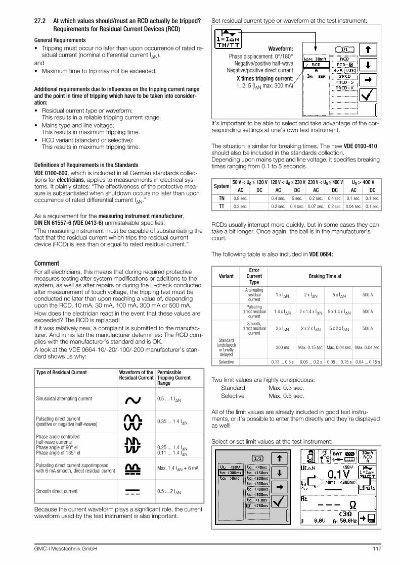
GMC-I Messtechnik GmbH 117
27.2 At which values should/must an RCD actually be tripped? Requirements for Residual Current Devices (RCD)
General Requirements• Tripping must occur no later than upon occurrence of rated re-
sidual current (nominal differential current IΔN).and• Maximum time to trip may not be exceeded.
Additional requirements due to influences on the tripping current range and the point in time of tripping which have to be taken into consider-ation:• Residual current type or waveform:
This results in a reliable tripping current range.• Mains type and line voltage:
This results in maximum tripping time.• RCD variant (standard or selective):
This results in maximum tripping time.
Definitions of Requirements in the StandardsVDE 0100-600, which is included in all German standards collec-tions for electricians, applies to measurements in electrical sys-tems. It plainly states: “The effectiveness of the protective mea-sure is substantiated when shutdown occurs no later than upon occurrence of rated differential current IΔN.”
As a requirement for the measuring instrument manufacturer, DIN EN 61557-6 (VDE 0413-6) unmistakable specifies:“The measuring instrument must be capable of substantiating the fact that the residual current which trips the residual current device (RCD) is less than or equal to rated residual current.”
CommentFor all electricians, this means that during required protective measures testing after system modifications or additions to the system, as well as after repairs or during the E-check conducted after measurement of touch voltage, the tripping test must be conducted no later than upon reaching a value of, depending upon the RCD, 10 mA, 30 mA, 100 mA, 300 mA or 500 mA.How does the electrician react in the event that these values are exceeded? The RCD is replaced!If it was relatively new, a complaint is submitted to the manufac-turer. And in his lab the manufacturer determines: The RCD com-plies with the manufacturer’s standard and is OK.A look at the VDE 0664-10/-20/-100/-200 manufacturer’s stan-dard shows us why:
Because the current waveform plays a significant role, the current waveform used by the test instrument is also important.
Set residual current type or waveform at the test instrument:
It’s important to be able to select and take advantage of the cor-responding settings at one’s own test instrument.
The situation is similar for breaking times. The new VDE 0100-410 should also be included in the standards collection. Depending upon mains type and line voltage, it specifies breaking times ranging from 0.1 to 5 seconds.
RCDs usually interrupt more quickly, but in some cases they can take a bit longer. Once again, the ball is in the manufacturer’s court.
The following table is also included in VDE 0664:
Two limit values are highly conspicuous:Standard Max. 0.3 sec.Selective Max. 0.5 sec.
All of the limit values are already included in good test instru-ments, or it’s possible to enter them directly and they’re displayed as well!
Select or set limit values at the test instrument:
Type of Residual Current Waveform of the Residual Current
Permissible Tripping Current Range
Sinusoidal alternating current 0.5 ... 1 IΔN
Pulsating direct current (positive or negative half-waves) 0.35 ... 1.4 IΔN
Phase angle controlled half-wave currents Phase angle of 90° el Phase angle of 135° el
0.25 ... 1.4 IΔN0.11 ... 1.4 IΔN
Pulsating direct current superimposed with 6 mA smooth, direct residual current Max. 1.4 IΔN + 6 mA
Smooth direct current 0.5 ... 2 IΔN
System50 V < U0 ≤ 120 V 120 V < U0 ≤ 230 V 230 V < U0 ≤ 400 V U0 > 400 V
AC DC AC DC AC DC AC DCTN 0.8 sec. 0.4 sec. 5 sec. 0.2 sec. 0.4 sec. 0.1 sec. 0.1 sec.
TT 0.3 sec. 0.2 sec. 0.4 sec. 0.07 sec. 0.2 sec. 0.04 sec. 0.1 sec.
VariantError
Current Type
Braking Time at
Alternating residual current
1 x IΔN 2 x IΔN 5 x IΔN 500 A
Pulsatingdirect residual
current1.4 x IΔN 2 x 1.4 x IΔN 5 x 1.4 x IΔN 500 A
Smooth, direct residual
current2 x IΔN 2 x 2 x IΔN 5 x 2 x IΔN 500 A
Standard (undelayed)
or briefly delayed
300 ms Max. 0.15 sec. Max. 0.04 sec. Max. 0.04 sec.
Selective 0.13 ... 0.5 s 0.06 ... 0.2 s 0.05 ... 0.15 s 0.04 ... 0.15 s
Phase displacement: 0°/180°
X times tripping current:
Negative/positive half-waveNegative/positive direct current
1, 2, 5 (IΔN max. 300 mA)
Waveform:

118 GMC-I Messtechnik GmbH
Tests for electrical systems include “visual inspection”, “testing” and “measurement”, and thus may only be conducted by experts with appropriate work experience.In the final analysis, the values from VDE 0664 are technically binding.
27.3 Testing Electrical Machines per DIN EN 60204 – Applications, Limit Values
Comparison of Tests Specified by the Standards
Uninterrupted Connection of a Protective ConductorUninterrupted connection of a protective conductor system is tested here by using an alternating current of 0.2 to 10 A with a line frequency of 50 Hz (= low-resistance measurement). Testing must be conducted between the mains circuit and the PE termi-nal (various points within the protective conductor system).
Loop Impedance MeasurementLoop impedance ZL-PE is measured and short-circuit current IK is ascertained in order to determine if the breaking requirements for protective devices have been fulfilled (see section 13). If loop measurement is not possible, e.g. where frequency converters are installed, mathematical calculation is required.
Insulation Resistance MeasurementAll of the active conductors in the primary circuit are short-cir-cuited at the machine (L and N, or L1, L2, L3 and N) and mea-sured against PE (protective conductor). Controllers or machine components which are not laid out for these voltages (500 V DC) can be disconnected from the measuring circuit for the duration of the measurement. The measured value may not be any less than 1 MΩ. The test can be subdivided into separate segments. A maximum resistance of 50 kΩ is required for the measurement of slip-rings etc.
Test for Absence of VoltageThe electrical equipment of the machine under test must with-stand a test voltage of twice its own rated voltage value or 1000 V~ (whichever is greater) applied between the conductors of all circuits and the protective conductor system for a period of at least 1 second. The test voltage must have a frequency of 50 Hz.
Residual Voltage MeasurementThe EN 60204 standard specifies that after switching supply power off, residual voltage must drop to a value of 60 V or less within 5 seconds at all accessible, active components of a machine to which a voltage of greater than 60 V is applied during operation.When conductors are exposed, residual voltage must have dropped to a value of 60 V or less within 1 second.
Function TestThe machine is operated with nominal voltage and tested for cor-rect functioning, in particular with regard to safety functions.
Special Tests• Pulse control mode for troubleshooting• Protective conductor test with 25 A test current
Limit Values per DIN EN 60204-1
Overvoltage Protection Device Characteristics for Limit Value Selection for Protective Conductor Testing
Testing per DIN EN 60204-1 Testing per DIN EN 61557 Mea-suring Func-tion
Continuity of the protective con-ductor system
Part 4: Resistance of earth connec-tion and equipotential bonding
RLO
Testing of fault loop impedance, and for suitability of the overcur-rent protective device
Part 3: Loop resistance ZLOOP
Insulation resistance tests Part 2: Insulation resistance RISO
Testing for dielectric strength
Part 14: Equipment for testing the safety of electrical equipment of ma-chinery
HV (PROFITEST PRIME AC only)
Protection against residual volt-age
Part 14: Equipment for testing the safety of electrical equipment of ma-chinery
Ures
Functions Tests — —
Measurement Parameters Cross-Section
Standard Value
Protective conductor measurement
Test duration 10 s
Limit value Protective conductor resis-tance based on phase conductor cross-section and characteristics of the overvoltage protection de-vice (calculated value)
1.5 mm²2.5 mm²4.0 mm²6.0 mm²10 mm² 16 mm² 25 mm² L(16 mm² PE)35 mm² L(16 mm² PE)50 mm² L(25 mm² PE)70 mm² L(35 mm² PE)95 mm² L(50 mm² PE)120 mm² L(70 mm² PE)
500 mΩ500 mΩ500 mΩ400 mΩ300 mΩ200 mΩ200 mΩ
100 mΩ
100 mΩ
100 mΩ
050 mΩ
050 mΩ
Insulation resistance measurement
Nominal voltage 500 V DC
Resistance limit value ≥ 1 MΩLeakage current measurement
Leakage current 2.0 mA
Protection against residual voltage
Discharge time after switching off supply power
5 s
Discharge time after exposing conductors
1 s
Testing for dielectric strength
Test voltage 2 x UN or 1 kV
Test voltage frequency 50 Hz or 60 Hz
Test duration 1 s
Breaking Time, Characteristics Available for Cross-SectionFuse breaking time: 5 s All cross-sections
Fuse breaking time: 0.4 s 1.5 through 16 sq. mm
Circuit breaker, characteristic BIa = 5 x In – breaking time: 0.1 s
1.5 through 16 sq. mm
Circuit breaker, characteristic CIa = 10x In – breaking time: 0.1 s
1.5 through 16 sq. mm
Adjustable circuit breakerIa = 8 x In – breaking time: 0.1 s
All cross-sections
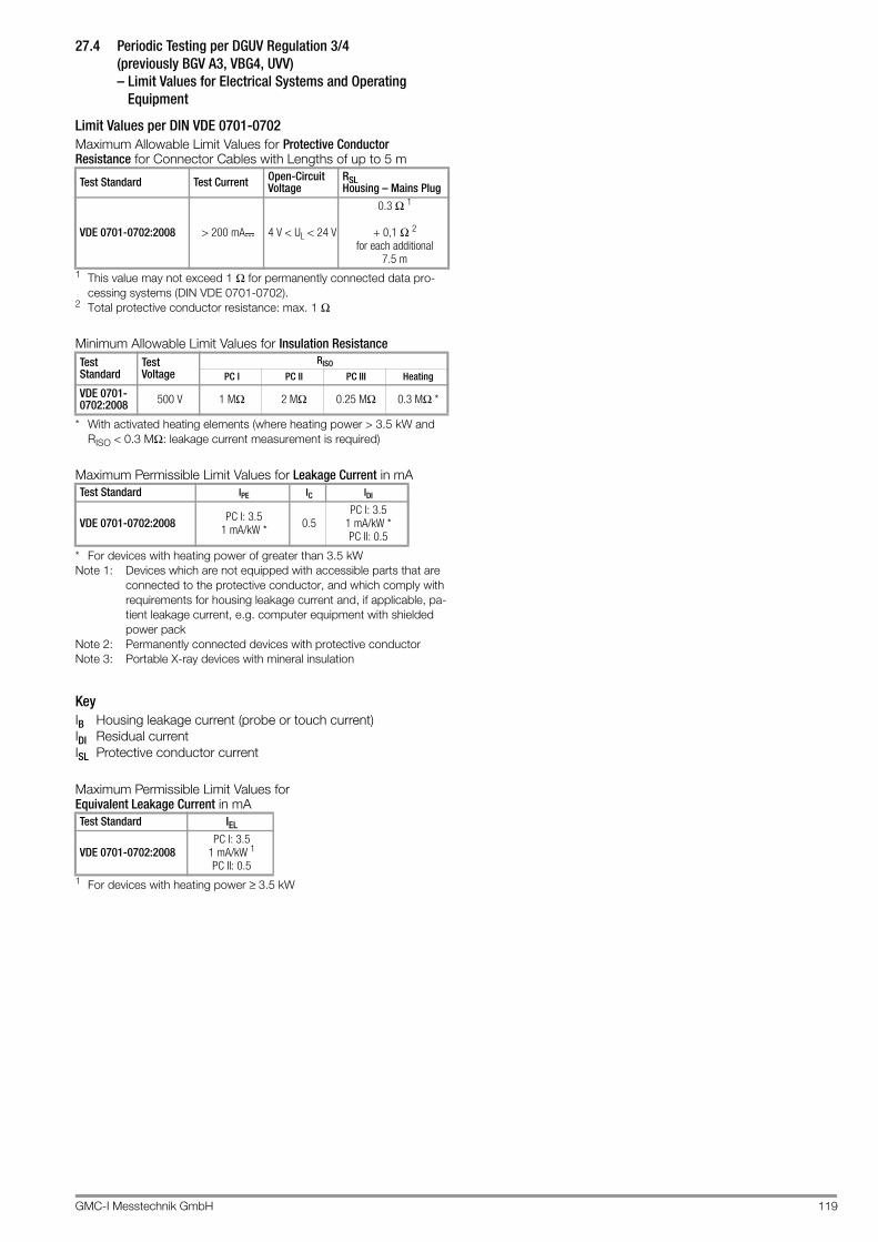
GMC-I Messtechnik GmbH 119
27.4 Periodic Testing per DGUV Regulation 3/4 (previously BGV A3, VBG4, UVV) – Limit Values for Electrical Systems and Operating
Equipment
Limit Values per DIN VDE 0701-0702Maximum Allowable Limit Values for Protective Conductor Resistance for Connector Cables with Lengths of up to 5 m
1 This value may not exceed 1 Ω for permanently connected data pro-cessing systems (DIN VDE 0701-0702).
2 Total protective conductor resistance: max. 1 Ω
Minimum Allowable Limit Values for Insulation Resistance
* With activated heating elements (where heating power > 3.5 kW and RISO < 0.3 MΩ: leakage current measurement is required)
Maximum Permissible Limit Values for Leakage Current in mA
* For devices with heating power of greater than 3.5 kWNote 1: Devices which are not equipped with accessible parts that are
connected to the protective conductor, and which comply with requirements for housing leakage current and, if applicable, pa-tient leakage current, e.g. computer equipment with shielded power pack
Note 2: Permanently connected devices with protective conductorNote 3: Portable X-ray devices with mineral insulation
KeyIB Housing leakage current (probe or touch current)IDI Residual currentISL Protective conductor current
Maximum Permissible Limit Values for Equivalent Leakage Current in mA
1 For devices with heating power ≥ 3.5 kW
Test Standard Test Current Open-Circuit Voltage
RSLHousing – Mains Plug
VDE 0701-0702:2008 > 200 mA 4 V < UL < 24 V
0.3 Ω 1
+ 0,1 Ω 2
for each additional7.5 m
Test Standard
Test Voltage
RISO
PC I PC II PC III Heating
VDE 0701-0702:2008 500 V 1 MΩ 2 MΩ 0.25 MΩ 0.3 MΩ *
Test Standard IPE IC IDI
VDE 0701-0702:2008 PC I: 3.51 mA/kW * 0.5
PC I: 3.51 mA/kW *PC II: 0.5
Test Standard IEL
VDE 0701-0702:2008PC I: 3.5
1 mA/kW 1
PC II: 0.5

120 GMC-I Messtechnik GmbH
27.5 List of Abbreviations and their Meanings in the Order They Appear on the Rotary Switch
U – Voltage Measurementf Line voltage frequency
fN Nominal frequency
U Voltage measured at the test probes during and after insu-lation measurement of RISO, or for the measurement of residual voltage Ures
UL-L Voltage between two phase conductors
UL-N Voltage between L and N
UL-PE Voltage between L and PE
UN Nominal line voltage
RLO – Low-resistance of Protective, Earthing and Bonding ConductorsRLO Resistance of equipotential bonding conductors,
designated RPE
RLO+ Resistance of equipotential bonding conductors (+ pole to PE)
RLO– Resistance of equipotential bonding conductors (– pole to PE)
Uq Open circuit voltage
ROFFSETOffset resistance for compensation of cables during low-resistance measurement
IHIGH High test current of 25 A for low-resistance measurement
RISO – Insulation Resistance MeasurementRISO Insulation resistance
UISO When measuring RISO: test voltage for ramp function: tripping or breakdown voltage
U Voltage measured at the test probes during and after insu-lation measurement RISO
RCD – Testing of Residual Current DevicesIΔ Tripping current
IΔN Nominal residual current
IN Nominal current
IF Rising test current (residual current)
IT Test current
RCD RCCB (residual current circuit breaker)
PRCD Portable residual current devicePRCD-S: with protective conductor detection and monitoringPRCD-K: with undervoltage trigger and protective con-ductor monitoring
RCD- Selective RCCB
RCBO RCCB / overcurrent protector (residual current operated circuit-breaker with overcurrent protection)
RE Calculated earth electrode loop resistance
SRCD Socket residual current device (permanently installed)
ta Time to trip / breaking time
UIΔ Touch voltage at moment of tripping
UIΔN Touch voltage relative to nominal residual current IΔN
UL Touch voltage limit value
ZLOOP – Loop Impedance MeasurementIK Calculated short-circuit current (at nominal voltage)
UL Touch voltage limit value
Z Loop impedance (ZL-N line impedance, ZL-PE loop impedance)
Ures Residual voltage measurementUres Measured residual voltage after discharge time tu, at
which voltage drops to 60 V or less
IMD – Insulation Monitoring Device
RCM – Residual Current Monitor
IL – leakage current measurement
≤1V≅ – IL/AMP leakage current (measurement with current clamp sensor)
T, %r.h. – Temperature / Atmospheric Humidityϑ Temperature in °C or °F
r. H. Relative humidity as percentage
HV – Testing for Dielectric Strength, HV AC (with the PROFITEST PRIME AC)ILIM Maximum current which may flow before high-voltage is
shut down (limit value to be specified)
I Shutdown current for the test for dielectric strength
Umax Test voltage to be specified for the test for dielectric strength
U Momentary test probe voltage
UD Breakdown voltage
t Rise time: time during which test voltage is increased to Umax
ton Test duration at maximum test voltage Umax (without rise time t )
Setup – Settings MenuUBatt (rechargeable) Battery voltage
Mains SystemIT system In IT systems, all active components are isolated from
earth, or one point is connected to earth via an imped-ance. The bodies of the electrical system are grounded either individually or mutually, or are mutu-ally connected to the system’s earthing.
TT system One point of the current source is directly grounded (French: terre terre).
TN systemAs opposed to TT systems, the electrical circuit is neu-tralized with the consuming system in TN systems (French: terre neutre)
S

GMC-I Messtechnik GmbH 121
27.6 Keyword Index
AAbbreviations ........................................................................120Adjusting Brightness and Contrast ..........................................22Automatic Test Sequences .....................................................84
BBatteries
Charge Level .....................................................................5Bibliography ..........................................................................122Bluetooth
Display Position .................................................................5Status Displays ................................................................94
CCharge Level ...........................................................................94Connecting a Bluetooth® Keyboard .......................................23Current Clamp Sensor
Measuring Range .............................................................70Current limiting in the Event of Arc-Over
........................................................................................13
DData Backup ...........................................................................12DB MODE ...............................................................................22Default Settings (GOME SETTING) ..........................................22
EElectric Charging Stations .......................................................76Electric Vehicles ......................................................................76Electrical Isolation ...................................................................13Error Acknowledgement ..........................................................91
FFirmware Revision and Calibration Information ........................24Firmware Update ....................................................................24Fuse
Mains Connection ..........................................................108Measuring Circuit ...........................................................108
IIMDs .......................................................................................63Insulation Monitoring Devices ..................................................63Interfaces
Configuring Bluetooth ......................................................23Internet Addresses ................................................................122
LLED Signals ......................................................................91, 92Limit Values
DIN EN 60204-1 ............................................................118DINVDE0701-0702 ........................................................119
Line Voltage (display of UL-N) .................................................56
MMains Connection Test – 3-Phase System ..............................93Mains Connection Test – Single-Phase System .......................93Memory
Occupancy Display ............................................................5Memory Occupancy ................................................................94MENNEKES Test Box .............................................................76
NNo-Trip Test ............................................................................51
OOn-Time
LCD Illumination ...............................................................22Test Instrument ................................................................22
Overview of Special Functions ................................................73
PParameter Lock ......................................................................26Plausibility Check ....................................................................26Polarity Reversal .....................................................................28Power Failure ..........................................................................13PRCD
Documentation of Fault Simulations at PRCDs with the PRO-FITEST PRCD Adapter ...................................... 77
Tripping Test, Type PRCD-K ........................................... 52Tripping Test, Type PRCD-S ........................................... 53
Protective MeasuresControl Circuit ................................................................. 13Inverters .......................................................................... 13Neutral Conductor ........................................................... 13PELV Circuits .................................................................. 13TN Systems .................................................................... 13
RRCD-S ................................................................................... 51RCMs ..................................................................................... 66Residual Current Monitoring Devices ...................................... 66Residual Voltage Test ............................................................. 62
SSafety
Personal .......................................................................... 13Safety Precautions, Rechargeable Lithium-Ion Battery ............ 12SCHUKOMAT ........................................................................ 53Short-Circuit Current Calculation ............................................ 57Shutdown Current
at Breakdown Voltage ..................................................... 83Pulse Control Mode ........................................................ 80
SIDOS .................................................................................... 53Signal Generator
Acoustic (repetitive sequence) ......................................... 79Signallampentest .................................................................... 18Spare key ............................................................................... 17SRCD ..................................................................................... 53Standard
DIN EN 50178 (VDE 160) ................................................ 51DIN EN 60 204 .............................................................. 118DIN VDE 0100 ................................................................. 56DIN VDE 0100-410 ......................................................... 52DIN VDE 0100-600 ................................................... 10, 57IEC 61851 ....................................................................... 76NIV/NIN SEV 1000 .......................................................... 10ÖVE/ÖNORM E 8601 ...................................................... 53ÖVE-EN 1 ....................................................................... 10VDE 0413 ....................................................................... 56
Switching BluetoothOn/Off ............................................................................. 23
Symbol ................................................................................... 12
TTest Sequences ..................................................................... 84Testing
DGUV Regulation 3 ....................................................... 119Electrical Machines ........................................................ 118
Touch Voltage ........................................................................ 42Type G RCCBs ....................................................................... 53
UUser Interface Language (CULTURE) ...................................... 22
VVoltage Drop Measurement .................................................... 74Voltage Test
User Interface Symbols ................................................... 14

122 GMC-I Messtechnik GmbH
27.7 Bibliography
27.7.1 Internet Addresses for Additional Information
Statutory Source DocumentsGerman occupational safety legislation (BetrSichV)Regulations issued by the accident insurance carriersTitle Information
Rule / RegulationPublisher Issue /
Order no.German occupational safety legislation (BetrSichV)
BetrSichV 2015
Electrical systems and equipment
DGUV regulation 3 (formerly BGV A3)
DGUV (formerly HVBG)
2005
VDE StandardsGerman standard Title Date of is-
suePublisher
DIN VDE 0100-410 Low-voltage electrical instal-lations – Part 410: Protec-tion for safety – Protection against electric shock
2007-06 Beuth-Verlag GmbH
DIN VDE 0100-530 Low-voltage electrical instal-lations – Part 530: Selection and erection of electrical equip-ment - Switchgear and con-trolgear
2011-06 Beuth-Verlag GmbH
DIN VDE 0100-600 Low-voltage electrical instal-lations – Part 6: Tests
2008-06 Beuth-Verlag GmbH
DIN EN 61557VDE 0413
Electrical safety in low volt-age distribution systems up to 1000 V AC and 1500 V DC – Equipment for testing, measuring or moni-toring of protective mea-sures
2007-12 Beuth-Verlag GmbH
DIN VDE 0105-100 Operation of electrical in-stallations – Part 100: Gen-eral requirements
2015-10 Beuth-Verlag GmbH
DIN EN 61851-1VDE 0122-1
Electric vehicle conductive charging system – Part 1: General requirements
2013-04 Beuth-Verlag GmbH
Further Literature in GermanTitle Author Publisher Issue /
Order no.Prüfung ortsfester und ortsveränderlicher Geräte
Bödeker, K. Lochthofen, M.
HUSS-MEDIEN GmbH Berlinwww.elektropraktiker.de
9th edition, 2016
DIN VDE 0100 richtig angewandt
Schmolke, H. VDE Verlag GmbH www.vde-verlag.de
VDE series Volume 1067th edition, 2016
Schutz gegen elektr. SchlagDIN VDE 0100-410
Hörmann, W.Schröder, B.
VDE Verlag GmbH www.vde-verlag.de
VDE series Volume 1404th edition, 2010
VDE-Prüfung nach BetrSichV, TRBS und DGUV-Vorschrift 3 (BGV A3)
Henning, W. Beuth-Verlag GmbHwww.beuth.de
VDE publication series 43 2015 edition
Merkbuch für den Elektrofachmann
GMC-I Messtech-nik GmbH
www.gossenme-trawatt.com
Order no. 3-337-038-01
de Jahrbuch 2014 Elektrotechnik für Handwerk und Industrie
Behrends, P.; Bonhagen, S.
Hüthig & Pflaum Verlag München/Heidelbergwww.elektro.net
ISBN 978-3-8101-0350-5
Elektroinstallation für die gesamte Ausbildung
Hübscher, Jagla, Klaue, Wickert
Westermann Schulbu-chverlag GmbHwww.westermann.de
ISBN 978-3-14-221630-0 4th edition, 2014
Praxis Elektrotechnik Klaus Tkotz, Thomas Käppel, Klaus Ziegler, Peter Braukhoff, Bernd Feustel
Europa-Lehrmittelwww.europa-lehrmit-tel.de
ISBN 978-3-8085-3266-9 13th edition, 2015
Fachkunde Elektrotechnik Europa-Lehrmittel www.europa-lehrmit-tel.de
ISBN 978-3-8085-3435-9, 30th edition, 2016
Internet Addresswww.dguv.de DGUV information, rules and regulations from German
statutory accident insurance
www.beuth.de VDE regulations, DIN standards, VDI directives from Beuth-Verlag GmbH
www.bgetem.de BG information, rules and regulations from the trade associationse.g. BG ETEM (trade association for energy, textiles and electrical medical devices)
www.zveh.de General Association of German Electricians

GMC-I Messtechnik GmbH 123
28 Return and Environmentally Sound Disposal
The instrument is a category 9 product (monitoring and control instrument) in accordance with ElektroG (German electrical and electronic device law). This device is subject to the RoHS direc-tive. We also make reference to the fact that in this regard, the current status can be accessed on the Internet at www.gossen-metrawatt.com by entering the search term WEEE.In accordance with WEEE 2012/19/EU and ElektroG, we identify our electrical and electronic devices with the sym-bol in accordance with DIN EN 50419 which is shown at the right. Devices identified with this symbol may not be disposed of with the trash. Please contact our service department regard-ing the return of old devices (see address in section 29).
Disposal of the Lithium-Ion BatteryIf the battery inserted in your instrument is no longer efficient, it must be properly disposed of in accordance with the applicable national regulations.
Attention!!The battery may only be replaced by GMC-I Service GmbH. Otherwise the warranty expires.
The German electrical and electronic device law (ElektroG) obliges us to describe the safe removal of the installed battery in the event of the disposal of the test instrument:1 As a first step, remove all cables from the front panel (espe-
cially all measurement and supply cables).2 Unscrew the 17 torx screws of the front panel with a screw
driver (the 4 cross-head screws may remain in place).3 Separate the battery plug-in connection (1) by removing the
5-pole ribbon cable from the circuit board, see figure below. Please ensure that the battery is not short-circuited during disassembly and disposal.
4 Cut through the two cable ties (2).5 Dispose of the battery according to the applicable regulations
or return it to GMC-I Service GmbH free of charge (address see section 29).
Figure: Disassembly of the Lithium-Ion Battery
1
2
2
AkkuLi-Ion

Edited in Germany • Subject to change without notice • PDF version available on the Internet
GMC-I Messtechnik GmbH Südwestpark 15 90449 Nürnberg • Germany
Phone:+49-911-8602-111Fax: +49 911 8602-777E-mail [email protected]
29 Repair and Replacement Parts ServiceCalibration Center* and Rental Instrument Service
If required please contact:
GMC-I Service GmbHService Center Beuthener Straße 41 90471 Nürnberg, GermanyPhone: +49-911-817718-0Fax: +49-911-817718-253e-mail: [email protected]
This address is only valid in Germany. Please contact our repre-sentatives or subsidiaries for service in other countries.
* DAkkS calibration laboratory for electrical quantities, registration no. D-K-15080-01-01,Accredited per DIN EN ISO/IEC 17025
Accredited quantities: direct voltage, direct current value, direct current resistance, alternating voltage, alternating current value, AC active power, AC apparent power, DC power, capacitance, frequency and temperature
Competent PartnerGMC-I Messtechnik GmbH is certified in accordance with DIN EN ISO 9001.Our DAkkS calibration laboratory is accredited by the Deutsche Akkreditierungsstelle GmbH (national accreditation body for the Federal Republic of Germany) under registration number D-K-15080-01-01 in accordance with DIN EN ISO/IEC 17025.We offer a complete range of expertise in the field of metrology: from test reports and factory calibration certificates right on up to DAkkS calibration certificates.Our spectrum of offerings is rounded out with free test equipment management.An on-site DAkkS calibration station is an integral part of our service department. If errors are discovered during calibration, our spe-cialized personnel are capable of completing repairs using original replacement parts.As a full service calibration laboratory, we can calibrate instru-ments from other manufacturers as well.
30 Product Support
If required please contact:
GMC-I Messtechnik GmbHProduct Support HotlinePhone +49-911-8602-0Fax: +49 911 8602-709E-mail [email protected]