profibus-dp slave - ftp.ruigongye.comftp.ruigongye.com/200802/2008051910592400001.pdf · protocol...
TRANSCRIPT

Protocol Interface Manual
PROFIBUS-DP Slave
Hilscher Gesellschaft für Systemautomation mbHRheinstraße 15
D-65795 HattersheimGermany
Tel. +49 (6190) 9907 - 0Fax. +49 (6190) 9907 - 50
Sales: +49 (6190) 9907 - 0Hotline and Support: +49 (6190) 9907 - 99
e-mail: [email protected]: http://www.hilscher.com

Index Date Version Chapter Revision
1 13.06.96 0.990 1.000
all Created
2 16.12.97 1.020 2, 32.3
DP Slave Information Structure added, C-Struct addedexplanation of the user diagnostic
3 09.12.98 1.021 new chapter 'message interface'
4 21.05.99 1.030 all added DPV1 messages, new diagnosis message and GET_PARAM message
5 09.07.99 1.032 all added GET_CONFIG message, updated naming of error constants
6 14.09.00 1.050 5.1.135.1.3
corrected range of Reason_Code variable to 0 ... 16fixed type in description of GET_CONFIG answer messageextend the parameter data chapter and protocol state section by new DEVICEswith 8kDual-port memory size.
7 26.07.02 1.051 5.1.7 Class1 write response message needs now number of written bytes inmsg.data_cnt
Although this software has been developed with great care and intensively tested, Hilscher Gesellschaft fürSystemautomation mbH cannot guarantee the suitability of this software for any purpose not confirmedby us in writing.Guarantee claims shall be limited to the right to require rectification. Liability for any damages whichmay have arisen from the use of this software or its documentation shall be limited to cases of intent.We reserve the right to modify our products and their specifiactions at any time in as far as this contribu-tes to technical progress. The version of the manual supplied with the software applies.
List of Revisions 2
Copyright * Hilscher Gesellschaft für Systemautomation mbH * Hotline and Support: +49 (6190) 9907-99 * Pi:DPS#7E

1 Introduction . . . . . . . . . . . . . . . . . . . . . . . . . . . . . . . . . . . . . . . . . . . . . . . . . . . . . . . . . . . . . . . . . . . . . . . . . . . . . . . . . . . . . . 4. . . . . . . .
1.1 Protocol Signification . . . . . . . . . . . . . . . . . . . . . . . . . . . . . . . . . . . . . . . . . . . . . . . . . . . . . . . . . . . . . . . . . . . . . . . . . 4. . . . . . . .
1.2 The Process Data Interface . . . . . . . . . . . . . . . . . . . . . . . . . . . . . . . . . . . . . . . . . . . . . . . . . . . . . . . . . . . . . . . . . . . . 4. . . . . . . .
2 Protocol Parameter . . . . . . . . . . . . . . . . . . . . . . . . . . . . . . . . . . . . . . . . . . . . . . . . . . . . . . . . . . . . . . . . . . . . . . . . . . . . . . . . 5. . . . . . . .
2.1 Using Device Driver Function to Write . . . . . . . . . . . . . . . . . . . . . . . . . . . . . . . . . . . . . . . . . . . . . . . . . . . . . . . . 5. . . . . . . .
2.2 Direct Write Access in Dual-Port Memory . . . . . . . . . . . . . . . . . . . . . . . . . . . . . . . . . . . . . . . . . . . . . . . . . . . . . 5. . . . . . . .
2.3 Activating Static Diagnostic . . . . . . . . . . . . . . . . . . . . . . . . . . . . . . . . . . . . . . . . . . . . . . . . . . . . . . . . . . . . . . . . . . 8. . . . . . . .
2.4 Serving the Watchdog Functionality . . . . . . . . . . . . . . . . . . . . . . . . . . . . . . . . . . . . . . . . . . . . . . . . . . . . . . . . . . . 9. . . . . . . .
3 Protocol State . . . . . . . . . . . . . . . . . . . . . . . . . . . . . . . . . . . . . . . . . . . . . . . . . . . . . . . . . . . . . . . . . . . . . . . . . . . . . . . . . . . . . 10. . . . . . .
3.1 Using Device Driver Functions . . . . . . . . . . . . . . . . . . . . . . . . . . . . . . . . . . . . . . . . . . . . . . . . . . . . . . . . . . . . . . . . 10. . . . . . .
3.2 Direct Read Access in Dual-Port Memory . . . . . . . . . . . . . . . . . . . . . . . . . . . . . . . . . . . . . . . . . . . . . . . . . . . . . 11. . . . . . .
4 Initialization Error Codes . . . . . . . . . . . . . . . . . . . . . . . . . . . . . . . . . . . . . . . . . . . . . . . . . . . . . . . . . . . . . . . . . . . . . . . . . 16. . . . . . .
5 The Message Interface . . . . . . . . . . . . . . . . . . . . . . . . . . . . . . . . . . . . . . . . . . . . . . . . . . . . . . . . . . . . . . . . . . . . . . . . . . . . 17. . . . . . .
5.1 The SPC3 Task . . . . . . . . . . . . . . . . . . . . . . . . . . . . . . . . . . . . . . . . . . . . . . . . . . . . . . . . . . . . . . . . . . . . . . . . . . . . . . . 17. . . . . . .
5.1.1 Sending Diagnostic Reports . . . . . . . . . . . . . . . . . . . . . . . . . . . . . . . . . . . . . . . . . . . . . . . . . . . . . . . . . . . . . 18. . . . . . .
5.1.2 Reading Parameter Data . . . . . . . . . . . . . . . . . . . . . . . . . . . . . . . . . . . . . . . . . . . . . . . . . . . . . . . . . . . . . . . . . 21. . . . . . .
5.1.3 Reading Configuration Data . . . . . . . . . . . . . . . . . . . . . . . . . . . . . . . . . . . . . . . . . . . . . . . . . . . . . . . . . . . . . 23. . . . . . .
5.1.4 DPV1 Class 1 Alarm Request . . . . . . . . . . . . . . . . . . . . . . . . . . . . . . . . . . . . . . . . . . . . . . . . . . . . . . . . . . . . 25. . . . . . .
5.1.5 DPV1 Class 1 Status Reports . . . . . . . . . . . . . . . . . . . . . . . . . . . . . . . . . . . . . . . . . . . . . . . . . . . . . . . . . . . . 27. . . . . . .
5.1.6 DPV1 Class 1 Read . . . . . . . . . . . . . . . . . . . . . . . . . . . . . . . . . . . . . . . . . . . . . . . . . . . . . . . . . . . . . . . . . . . . . 29. . . . . . .
5.1.7 DPV1 Class 1 Write . . . . . . . . . . . . . . . . . . . . . . . . . . . . . . . . . . . . . . . . . . . . . . . . . . . . . . . . . . . . . . . . . . . . . 31. . . . . . .
5.1.8 DPV1 Class 2 Init . . . . . . . . . . . . . . . . . . . . . . . . . . . . . . . . . . . . . . . . . . . . . . . . . . . . . . . . . . . . . . . . . . . . . . . 33. . . . . . .
5.1.9 DPV1 Class 2 Initiate . . . . . . . . . . . . . . . . . . . . . . . . . . . . . . . . . . . . . . . . . . . . . . . . . . . . . . . . . . . . . . . . . . . 35. . . . . . .
5.1.10 DPV1 Class 2 Read . . . . . . . . . . . . . . . . . . . . . . . . . . . . . . . . . . . . . . . . . . . . . . . . . . . . . . . . . . . . . . . . . . . . 37. . . . . . .
5.1.11 DPV1 Class 2 Write . . . . . . . . . . . . . . . . . . . . . . . . . . . . . . . . . . . . . . . . . . . . . . . . . . . . . . . . . . . . . . . . . . . . 39. . . . . . .
5.1.12 DPV1 Class 2 Data Transport . . . . . . . . . . . . . . . . . . . . . . . . . . . . . . . . . . . . . . . . . . . . . . . . . . . . . . . . . . 41. . . . . . .
5.1.13 DPV1 Class 2 Abort . . . . . . . . . . . . . . . . . . . . . . . . . . . . . . . . . . . . . . . . . . . . . . . . . . . . . . . . . . . . . . . . . . . 43. . . . . . .
5.1.14 DPV1 Class 2 Aborted . . . . . . . . . . . . . . . . . . . . . . . . . . . . . . . . . . . . . . . . . . . . . . . . . . . . . . . . . . . . . . . . . 45. . . . . . .
5.1.15 DPV1 Class 2 Fault . . . . . . . . . . . . . . . . . . . . . . . . . . . . . . . . . . . . . . . . . . . . . . . . . . . . . . . . . . . . . . . . . . . . 45. . . . . . .
Table of Contents 3
Copyright * Hilscher Gesellschaft für Systemautomation mbH * Hotline and Support: +49 (6190) 9907-99 * Pi:DPS#7E

1 Introduction
This manual describes the user interface of PROFIBUS-DP-SLAVE for thecommunication interfaces and the communication module. The aim of thismanual is to support the integration of these devices into own applications basedon device driver functions or direct access into the dual-port memory. The general mechanism for the data transfer is protocol independent and descri-bed in the 'general definitions' of the toolkit manual.All parameter and data have basically the description LSB/MSB. Thiscorresponds to the convention of the Microsoft-C-compiler.
1.1 Protocol Signification
To manage the PROFIBUS-DP Slave protocol 2 tasks are involved in the system.Therefore following entries for the protocol signification in the variablesTaskiName of the dual-port memory are done: Task2Name: 'PLCDPS 'Task3Name: 'SPC3CTRL'
1.2 The Process Data Interface
The DEVICE handles 512 bytes send and 512 bytes receive process data in thelower kbyte of the dual-port memory for the PROFIBUS-DP on the CIF30-DPS/COM-DPS/CIF 104-DPS and 3584 bytes send and 3584 bytes for thePROFIBUS-DP on the CIF 80-DPS,PMC-DPS CIF 104P-DPS. To exchange thedata between the DEVICE and the HOST use the device driver function De-vExchangeIO()or read and write directly into these locations.After calling the function DevExchangeIO()the function decides on its ownwhich handhake mechanism has to be used to read and write the process data inthe rigth manner from and to the DEVICE. If these locations are accessed directlywithout using the device driver functionality, than you have to use the righthandshake mechanism to ensure that the data is handed over safety and valid. Seechapter 'IO Communication with a Process Image' in the 'toolkit general definiti-ons' manual.
CIF 30-DPS / COM-DPS / CIF 104-DPS / CIF60-DPS old rev.:Parameter Address Description
SndPd 000h Send Process Data (HOST → DEVICE → Network)
RecvPd 200h Receive Process Data (Network → DEVICE → HOST)
CIF 80-DPS / PMC-DPS / CIF 104P-DPS / CIF 60-DPS new rev.Parameter Address Description
SndPd 000h Send Process Data (HOST → DEVICE → Network)
RecvPd E00h Receive Process Data (Network → DEVICE → HOST)
Introduction 4
Copyright * Hilscher Gesellschaft für Systemautomation mbH * Hotline and Support: +49 (6190) 9907-99 * Pi:DPS#7E

2 Protocol Parameter
Some important parameter can be handed over to the DEVICE online. They havea higher priority than the static parameter in the internal FLASH memory.
2.1 Using Device Driver Function to Write
To hand over these parameter use the device driver functionDevPutTaskParameter(). For parameter usNumber use value 2, becausethe parameter must handed over to the task 2. For parameter usSize use value64, to fix the length of the structure. Point the parameter pvData to a data areaof the following structure.typedef struct DPS_TASK_PARAMETERtag {
unsigned char bPlcMode; /* PLC mode */ unsigned short usWatchdogTime; /* host watchdog time */ unsigned char abReserved1[5]; unsigned char bBusAddr; /* bus address */ unsigned char abReserved2[1]; unsigned char bMasterForceConfig;/* configuration by Chk_Cfg */ unsigned char bDpv1C1BufLen; /* length of DPV1 class 1 buffer */ unsigned char bDpv1C2BufLen; /* length of DPV1 class 2 buffer */ unsigned char bMiscUserFlags; /* misc. flags for user */ unsigned char bMiscTaskFlags; /* misc. flags for task */ unsigned char bBufferLen; /* length of PARA_DIAG_BUFFER */
union {
struct {
unsigned char bType; /* type of module */ unsigned char bLen; /* length of module */
} MODULE[24];
struct {
unsigned char abExtDiagData[32];/* extended diagnostic data */ unsigned char abReserved3[16];
} DIAG_DATA;
} BUFFER;
} DPS_TASK_PARAMETER;
After setting up the structure and fixing it with DevPutTaskParameter(),the warmstart command must be performed with the DevReset()function. Themost important parameter in this function usMode must be set up to 3 =WARMSTART. After the warmstart is finished without error the new parametersare active.
2.2 Direct Write Access in Dual-Port Memory
First the parameter must be written down into the corresponding area of the dual-port memory. Then a warmstart command must be activated by setting the Initbit in the variable DevFlags. Then the DEVICE will set them valid. (See thechapter 'initialization of the DEVICE' in the toolkit manual 'general definitions'for a description of the init procedure).
Protocol Parameter 5
Copyright * Hilscher Gesellschaft für Systemautomation mbH * Hotline and Support: +49 (6190) 9907-99 * Pi:DPS#7E

CIF 30-DPS / COM-DPS / CIF 104-DPS / CIF60-DPS old rev.:
Refe-rence
Parameter Addr. Size Value Description
Mode bPlcMode 6C0h 1 byte 0 ... 3 mode of exchanging processdata
usWatchdogTime 6C1h 1 word control time of the host watchdogin milliseconds (ignored if zero)
abReserved1[5] 6C3h 5 bytes 0 do not modify
Setup bBusAddr 6C8h 1 byte 0 ..125 bus address
abReserved2[1] 6C9h 1 byte 0 do not modify
bMasterForceConfig
6CAh 1 byte 0 ... 1 0: Chk_Cfg telegram data will be compared to internal config.1: Chk_Cfg telegram data will be accepted as valid config.
bDpv1C1BufLen 6CBh 1 byte 0, 4 ...244
length of DPV1 class 1 buffer
bDpv1C2BufLen 6CCh 1 byte 0, 48...244
length of DPV1 class 2 buffer
bMiscUserFlags 6CDh 1 byte flags for user (do not modify)
bMiscTaskFlags 6CEh 1 byte flags for task (do not modify)
Modules
bBufferLen 6CFh 1 byte 2 ... 48 number of valid bytes, whichfollow in the modul area
MODULE[0].bType 6D0h 1 byte012345678
type of the first moduleinput byte without consistencyinput word without consistencyoutput byte without consistencyoutput word without consistencyinput byte with consistencyinput word with consistencyoutput byte with consistencyoutput word with consistencydummy place
MODULE[0].bLen 6D1h 1 byte
0123456789
number of elements (byte orword see 'Module type') of thefirst module1 Byte/Word2 Bytes/Words3 Bytes/Words4 Bytes/Words8 Bytes/Words12 Bytes/Words16 Bytes/Words20 Bytes/Words32 Bytes/Words64 Bytes/Words
MODULE[1].bType 6D2h 1 byte 0 ... 8 type of the second module
MODULE[1].bLen 6D3h 1 byte 0 ... 9 number of elements of thesecond module
... ... ... ...
MODULE[23].bType
6FEh 1 byte 0 ... 8 type of the 24th module
MODULE[23].bLen 6FFh 1 byte 0 ... 9 number of elements of the 24thmodule
Protocol Parameter 6
Copyright * Hilscher Gesellschaft für Systemautomation mbH * Hotline and Support: +49 (6190) 9907-99 * Pi:DPS#7E

CIF 80-DPS / PMC-DPS / CIF 104P-DPS / CIF 60-DPS new rev.
Refe-rence
Parameter Addr. Size Value Description
Mode bPlcMode 1EC0h 1 byte 0 ... 3 mode of exchanging processdata
usWatchdogTime 1EC1h 1 word control time of the host watchdogin milliseconds (ignored if zero)
abReserved1[5] 1EC3h 5 bytes 0 do not modify
Setup bBusAddr 1EC8h 1 byte 0 ..125 bus address
abReserved2[1] 1EC9h 1 byte 0 do not modify
bMasterForceConfig
1ECAh 1 byte 0 ... 1 0: Chk_Cfg telegram data will be compared to internal config.1: Chk_Cfg telegram data will be accepted as valid config.
bDpv1C1BufLen 1ECBh 1 byte 0, 4 ...244
length of DPV1 class 1 buffer
bDpv1C2BufLen 1ECCh 1 byte 0, 48...244
length of DPV1 class 2 buffer
bMiscUserFlags 1ECDh 1 byte flags for user (do not modify)
bMiscTaskFlags 1ECEh 1 byte flags for task (do not modify)
Modules
bBufferLen 1ECFh 1 byte 2 ... 48 number of valid bytes, whichfollow in the modul area
MODULE[0].bType 1ED0h 1 byte012345678
type of the first moduleinput byte without consistencyinput word without consistencyoutput byte without consistencyoutput word without consistencyinput byte with consistencyinput word with consistencyoutput byte with consistencyoutput word with consistencydummy place
MODULE[0].bLen 1ED1h 1 byte
0123456789
number of elements (byte orword see 'Module type') of thefirst module1 Byte/Word2 Bytes/Words3 Bytes/Words4 Bytes/Words8 Bytes/Words12 Bytes/Words16 Bytes/Words20 Bytes/Words32 Bytes/Words64 Bytes/Words
MODULE[1].bType 1ED2h 1 byte 0 ... 8 type of the second module
MODULE[1].bLen 1ED3h 1 byte 0 ... 9 number of elements of thesecond module
... ... ... ...
MODULE[23].bType
1EFEh 1 byte 0 ... 8 type of the 24th module
MODULE[23].bLen 1EFFh 1 byte 0 ... 9 number of elements of the 24thmodule
Protocol parameter in area Task2Parameter
Protocol Parameter 7
Copyright * Hilscher Gesellschaft für Systemautomation mbH * Hotline and Support: +49 (6190) 9907-99 * Pi:DPS#7E

2.3 Activating Static Diagnostic
The HOST can activate a diagnostic request which is reported to the PROFIBUSmaster during runtime. The cyclic data exchange will be suspended and the cardswitches into a diagnostic mode and reports static diagnosis to the master.The static diagnosis data can be extendend by up to 32 bytes of user specific data.These data have to be filled into a special area of the dual-port memory prior toactivating the diagnostic mode. The structure of the data area is shown below.
CIF 30-DPS / COM-DPS / CIF 104-DPS / CIF60-DPS old rev.:Parameter Addr. Size Value
RangeDescription
bMiscTaskFlags 6CEh 1 byte Bit 0 = 1: don't set the Ext_Diag_Data bit in the standard diagnostic data even if user diagnostic data are present 0: indicate the availability of user diag data in Ext_Diag_data bitBit 1 ... 7: reserved (do not modify)
bBufferLen 6CFh 1 byte 0...32 number of valid bytes which follow in thediagnostic user data area
abExtDiagData[32] 6D0h 32 byte diagnostic user data
CIF 80-DPS / PMC-DPS / CIF 104P-DPS / CIF 60-DPS new rev.Parameter Addr. Size Value
RangeDescription
bMiscTaskFlags 1ECEh 1 byte Bit 0 = 1: don't set the Ext_Diag_Data bit in the standard diagnostic data even if user diagnostic data are present 0: indicate the availability of user diag data in Ext_Diag_data bitBit 1 ... 7: reserved (do not modify)
bBufferLen 1ECFh 1 byte 0...32 number of valid bytes which follow in thediagnostic user data area
abExtDiagData[32] 1ED0h 32byte
diagnostic user data
To transfer the extended diagnostic data you should fill the data into the dual-portmemory first and store its length into the parameter bBufferLen.The data in the diagnostic user data area will be checked for its conformity to thePROFIBUS DP and DPV1 specification. If a violation of the specification is de-tected the diagnostic user data will be ignored. Instead only a simple static dia-gnosis (without user specific data) will be reported to the master. Please note thatit is not allowed to send alarms in a static diagnosis. To activate alarms the mes-sage based interface of the DEVICE must be used which is described later in thismanual. Bit 0 of the variable bMiscTaskFlags should be set to one in order to forcethe Ext_Diag_Data bit of the standard diagnostic data to zero. If bit 0 ofbMiscTaskFlags is set to zero the Ext_Diag_Data bit will be set to oneonly if diagnostic user data are present.The diagnostic mode can be activated by setting the bit NotReady of the Dev-Flags cell. If you are using the device driver library the function DevSe-tHostState() should be called with parameter HOST_NOT_READY.
Protocol Parameter 8
Copyright * Hilscher Gesellschaft für Systemautomation mbH * Hotline and Support: +49 (6190) 9907-99 * Pi:DPS#7E

2.4 Serving the Watchdog Functionality
If the Dual-Port memory watchdog-functionality described in the manual 'toolkitgeneral definitions' was started once and is not served any longer by HOST pro-gram because of an error the DEVICE sets the simple static diagnostic mode asdescribed above on its own. In this case the DEVICE must be restarted again byeither a cold start or warm start command, else it won't get operative any more.
Protocol Parameter 9
Copyright * Hilscher Gesellschaft für Systemautomation mbH * Hotline and Support: +49 (6190) 9907-99 * Pi:DPS#7E

3 Protocol State
The protocol state variables built by the DEVICE form the diagnostic interfacebetween the HOST and the DEVICE. The following structure contains in-formation of the DP slave. The table shows the variables with their location in thedual-port memory.
3.1 Using Device Driver Functions
Use the device driver function DevGetTaskState() to read the state varia-bles. For parameter usNumber use value 2, because the parameter must be readfrom the task state area of the task 2. For parameter usSize use value 64, whichis the length of the structure below. Point pvData to the following structure.
typedef struct DPS_INFO_STRUCTUREtag {
unsigned short bBaudrate; unsigned char bAdresse; unsigned char bIdentLow; unsigned char bIdentHigh; unsigned short usTaskState; unsigned short usMaxEDpmData; unsigned short usMaxADpmData; unsigned short usErrCnt; unsigned char bLastError; unsigned char bIrq; unsigned char bIrqPol; unsigned short usDevManu; unsigned short usDevType; unsigned short usDevModel; unsigned short usIrqEvent; unsigned short usIrqCnt; unsigned char bAdrSwitch; unsigned char bDevTabEnt; /* entrance number in device table */ unsigned char bModuleCnt; /* number of module */ unsigned short usIOFieldLen; /* length of field IO in SPC3 */ unsigned char bKByteFieldLen; /* length of field identific. im SPC3 */ unsigned char bParamFieldLen; /* length of field Parameter in SPC3 */ unsigned char bDiagFieldLen; /* length of field Diag in SPC3 */ unsigned char bParamUser; unsigned char bParamState;
} DPS_INFO_STRUCTURE;
Protocol State 10
Copyright * Hilscher Gesellschaft für Systemautomation mbH * Hotline and Support: +49 (6190) 9907-99 * Pi:DPS#7E

3.2 Direct Read Access in Dual-Port Memory
Read the bus state structure directly from the following dual-port memorylocation:
CIF 30-DPS / COM-DPS / CIF 104-DPS / CIF60-DPS old rev.:Parameter Address Value Description
Baud rate(in kBaud)
740h120006000300015005001879390
Last detected baud rate12 MBaud6 MBaud3 MBaud1.5 MBaud500 kBaud187.5 kBaud93,75 kBaud9600 Baudnot detected
Bus Address 742h 1 .. 126 Actual configured bus address.
continued on next page
Protocol State 11
Copyright * Hilscher Gesellschaft für Systemautomation mbH * Hotline and Support: +49 (6190) 9907-99 * Pi:DPS#7E

Parameter Address Value Description
Ident Number 743h 7 5 0 47 5 0 37 5 0 1
CIF 30-DPS, CIF 104-DPSPKV 30-DPSCOM-DPS
Task State 745h xxx1
xx1x
x1xx
1xxx
Task is during initialization. If this state stays for some seconds, theconfiguration parameter may be invalid.
Task runningThe initialization happened without error,Generally the task is able to runcommunication on the bus.
Static DiagnosisSlave diagnosis telegrams will be sent at themoment on the bus.
Data exchangeThe data exchange mode is active. Theuser-data will be transfered on the busbetween the master and the slave actually.
INPUT Length 747h 0 - 244 Length of the inputs in bytes *
OUTPUT Length 749h 0 - 244 Length of the outputs in bytes *
Error Cnt 74Bh 0 - 65535 Number of errors
Last Error 74Dh 0 - 255 Last error that happened
Interrupt 74Eh for internal use
Interrupt Polling 74Fh for internal use
Device Manufactor 750h for internal use
Device Type 752h for internal use
Device Modell 754h for internal use
Interrupt Event 756h for internal use
Interrupt Count 758h for internal use
Address Switch 75Ah for internal use
Device Table Entry 75Bh Number of entrances in device table
Module Count 75Ch 0 - 33 Number of modules
IO Length Field 75Dh Length of IO field
Identification FieldLength
75Fh Length of identification field
Parameter FieldLength
760h Length of paramter field
Diag Field Length 761h Length of the field Diagnostic
Parameter User 762h for internal use
Paramter State 763h for internal use
DP Slave Information Structure
* Depending on internal resources of the SPC3 the maximum length of the sum inputsand outputs is limited to 368 bytes.
Protocol State 12
Copyright * Hilscher Gesellschaft für Systemautomation mbH * Hotline and Support: +49 (6190) 9907-99 * Pi:DPS#7E
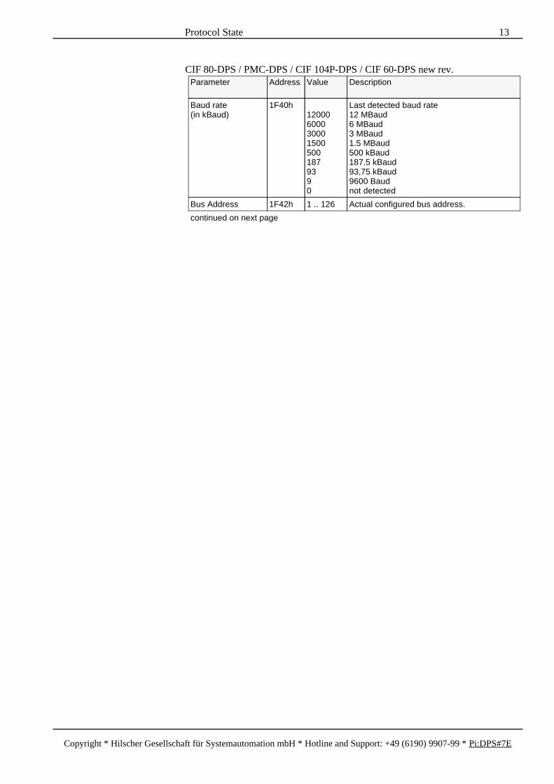
CIF 80-DPS / PMC-DPS / CIF 104P-DPS / CIF 60-DPS new rev.Parameter Address Value Description
Baud rate(in kBaud)
1F40h120006000300015005001879390
Last detected baud rate12 MBaud6 MBaud3 MBaud1.5 MBaud500 kBaud187.5 kBaud93,75 kBaud9600 Baudnot detected
Bus Address 1F42h 1 .. 126 Actual configured bus address.
continued on next page
Protocol State 13
Copyright * Hilscher Gesellschaft für Systemautomation mbH * Hotline and Support: +49 (6190) 9907-99 * Pi:DPS#7E
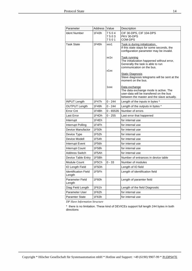
Parameter Address Value Description
Ident Number 1F43h 7 5 0 47 5 0 37 5 0 1
CIF 30-DPS, CIF 104-DPSPKV 30-DPSCOM-DPS
Task State 1F45h xxx1
xx1x
x1xx
1xxx
Task is during initialization. If this state stays for some seconds, theconfiguration parameter may be invalid.
Task runningThe initialization happened without error,Generally the task is able to runcommunication on the bus.
Static DiagnosisSlave diagnosis telegrams will be sent at themoment on the bus.
Data exchangeThe data exchange mode is active. Theuser-data will be transfered on the busbetween the master and the slave actually.
INPUT Length 1F47h 0 - 244 Length of the inputs in bytes *
OUTPUT Length 1F49h 0 - 244 Length of the outputs in bytes *
Error Cnt 1F4Bh 0 - 65535 Number of errors
Last Error 1F4Dh 0 - 255 Last error that happened
Interrupt 1F4Eh for internal use
Interrupt Polling 1F4Fh for internal use
Device Manufactor 1F50h for internal use
Device Type 1F52h for internal use
Device Modell 1F54h for internal use
Interrupt Event 1F56h for internal use
Interrupt Count 1F58h for internal use
Address Switch 1F5Ah for internal use
Device Table Entry 1F5Bh Number of entrances in device table
Module Count 1F5Ch 0 - 33 Number of modules
IO Length Field 1F5Dh Length of IO field
Identification FieldLength
1F5Fh Length of identification field
Parameter FieldLength
1F60h Length of paramter field
Diag Field Length 1F61h Length of the field Diagnostic
Parameter User 1F62h for internal use
Paramter State 1F63h for internal use
DP Slave Information Structure
* there is no limitation. These kind of DEVICEs support full length 244 bytes in bothdirections
Protocol State 14
Copyright * Hilscher Gesellschaft für Systemautomation mbH * Hotline and Support: +49 (6190) 9907-99 * Pi:DPS#7E

Baud RateThe baud rate will be detected automatically by the SPC3. If no valid telegramshave been received, the slave checks all other baud rates until valid telegrams arereceived. Up this time the last valid baud rate will be displayed.
Ident NumberThis field shows the from PROFIBUS Trademark Organisation (PTO) givenidentification code of the slave.
Task StateThe parameter description of 'task state' stands a 'x' for 'don't care'. If the taskstate shows the value 'task initialization' for some seconds, the configuration hasto be checked.After successful initialization the state 'task running' will be reached. The task isready for communication. This task state remains active until the DEVICE is re-set by the application.If bus communication is running, the states 'diagnosis' and 'data exchange' givemore information about the kind of communication. Reasons to run diagnosis canbe the one of the following:
the user program demands diagnosis (please refer to the description of the userprogram).
the DP slave demands diagnostic mode on itself, if internal errors happen.
the DP master can't start with data exchange because of the slave behaviour.
the DP master demands diagnosis, because its user program (or CPU of thePLC) or internal state does not allow to change to data exchange (please referto the documentation of the master).
By reaching the state 'data exchange', the process-data will be updated betweenDP master and DP slave - the data transfer is running.
INPUT Length, OUTPUT LengthThe calculated length of the input-data will be displayed in the field INPUTLength, those of the output-data in the field OUTPUT Length. Please note, thatdepending on the resources of the SPC 3, the sum of both is restricted. The limi-tations can be found in the chapter 'technical data' in the hardware-manual.
Error Cnt, Last ErrorError Cnt shows, how many errors happened since the last cold-/warmstart. LastError gives more information about the last error that happened.
Protocol State 15
Copyright * Hilscher Gesellschaft für Systemautomation mbH * Hotline and Support: +49 (6190) 9907-99 * Pi:DPS#7E

4 Initialization Error Codes
The following error description should help to solve problems quickly which canoccure during the initialization of the card.
Error number Description
52 DPS_ERR_INIT_BUS_ADDRESSInvalid bus address configured, valid addresses are 1 ... 125
53 DPS_ERR_INIT_WAIT_FOR_WARMSTARTWaiting for warmstart, the parameter 'starting mode' in the table'setup' is configured to the value 'configuration by application' but theapplication has not made a warmstart to the device yet.
54 DPS_ERR_INIT_MODULE_TYPEInvalid module type configured, the configured module type code isunknown. If this error happens after a warmstart check also thebuffer_len and contact the developer of the user program.
55 DPS_ERR_INIT_MODULE_LENGTHInvalid module length, the code for the parameter module length isnot defined.
61 DPS_ERR_INIT_NO_ADR_SWITCHCurrent configuration data require to read read the bus address fromhardware switches but there are not switches on this hardware
63 DPS_ERR_INIT_PLC_MODEHandshake mode is not supported
70 DPS_ERR_INIT_IO_LENInvalid length of i/o data, the maximum length of i/o data has beenexceeded or no i/o modules were specified.
72 DPS_ERR_INIT_DPV1_C1_BUF_LENIllegal DPV1 class 1 buffer length
73 DPS_ERR_INIT_DPV1_C2_BUF_LENIllegal DPV1 class 2 buffer length
74 DPS_ERR_INIT_SPC3_NOFFSPC3 chip not in offline mode during initialization
75 DPS_ERR_INIT_SPC3_LESS_MEMNot enough memory in SPC3 for all buffers
76 DPS_ERR_INIT_DIN_DOUT_BUF_LENIllegal i/o data buffer length
77 DPS_ERR_INIT_DIAG_BUF_LENIllegal diagnostic buffer length
78 DPS_ERR_INIT_PRM_BUF_LENIllegal parameter buffer length
79 DPS_ERR_INIT_CFG_BUF_LENIllegal config buffer length
80 DPS_ERR_INIT_SSA_BUF_LENIllegal SSA buffer length
210 TASK_F_DATABASENo database could be found in the DEVICE
Initializtion error of the task SPC3CTRL
Error Codes 16
Copyright * Hilscher Gesellschaft für Systemautomation mbH * Hotline and Support: +49 (6190) 9907-99 * Pi:DPS#7E

5 The Message Interface
The following send and receive messages are exchanged with the DEVICE via itsmailboxes in the structure like it is described in the chapter 'definition of themessage interface' in the toolkit manual. To put and get messages to respectively from the DEVICE through its mailboxesuse the device driver functions DevPutMessage() or DevGetMessage().With direct access to the dual-port memory you must write the message in theDevMailbox or read the message out of the HostMailbox with thehandshake mechanism described in the toolkit manual.The structures of this messages and its values are described in the sections below.
5.1 The SPC3 Task
The SPC3-Task manages the process input and output data coming from and go-ing to the Siemens DP slave chip SPC3. Therefore the task communicates inter-rupt controlled to it via the dual-port memory of this chip. It manages the confi-guration and parameterization and handles the PROFIBUS-DP diagnostic reports.The task has implemented the following functions:
process data handshake with the SPC3 chip.
checking the master I/O configuration with the internal I/O configuration
handling of single diagnostic requests of the HOST application
handling of DPV1 class 1 and class 2 indications
The Message Interface 17
Copyright * Hilscher Gesellschaft für Systemautomation mbH * Hotline and Support: +49 (6190) 9907-99 * Pi:DPS#7E

5.1.1 Sending Diagnostic Reports
The HOST application can send a single diagnostic request to the PROFIBUS-DPmaster by means of the command message DPS_B_DIAG.
Command Message
Message Header Variable Type Value Description
msg.rx byte 3 receiver: SPC3 task
msg.tx byte 16 transmitter: user at HOST
msg.ln byte 8+m message length(m: number of bytes in data area)
msg.nr byte j number of message (optional)
msg.a byte 0 no answer
msg.f byte 0 no error
msg.b byte 24 command: DPS_B_DIAG
msg.e byte 0 not used
Telegram Header msg.device_adr byte 0 not used
msg.data_area byte 0 not used
msg.data_adr word 0 not used
msg.data_idx byte 0 not used
msg.data_cnt byte 0 ... 32 (m) number of extended diagnostic data bytes
msg.data_type byte Bit 0 = 1: don't set the Ext_Diag_Data bit in the standard diagnostic data even if user diagnostic data are presentBit 1 ... 7: reserved
msg.function byte 18 function: DPS_FUNC_SINGLE_DIAG
Data msg.d[0] byte extended diagnostic data byte 1
... ... ... ...
msg.d[m-1] byte extended diagnostic data byte m
The single diagnosis command causes the DP slave to send a diagnosis request tothe master exactly once. After fetching the diagnostic data from the slave devicethe master will continue exchanging process data.The command DPS_B_DIAG must be filled into the msg.b variable to mark adiagnosis message. The variable msg.function must be set to DPS_FUN-C_SINGLE_DIAG as the only supported mode is "Single Diagnosis" mode.The standard diagnostic data of 6 bytes which are internally generated can be ex-tended by user specific data. Up to 32 bytes of user diagnostic can be handled bythe DEVICE. These data have to be filled into the user data area at msg.d. Thevariable msg.data_cnt should be set according to the number of user diagno-stic data bytes given.All user diagnostic data will be checked for conformity with the PROFIBUS DPand DPV1 specification. The following types of user diagnostic data aresupported:
device related diagnosis (DP mode only),
id related diagnosis,
channel related diagnosis,
revision number (only one per diagnosis request),
The Message Interface 18
Copyright * Hilscher Gesellschaft für Systemautomation mbH * Hotline and Support: +49 (6190) 9907-99 * Pi:DPS#7E

For a detailed description of each of the different diagnosis types and its formats,please refer to the PROFIBUS DP and DPV1 specification.Setting bit 0 of the variable msg.type to one forces the DEVICE to set the Ex-t_Diag_Flag of the standard diagnostic data to zero even if user diagnosticdata are present. If the bit 0 is set to zero the Ext_Diag_Flag will indicate theavailability of user diagnostic data in the diagnosis telegram.An answer message is returned by the DEVICE which informs about the success-ful processing or failure of the diagnostic request. However, this message provi-des no indication whether the diagnostic request was already fetched by themaster.The structure of the answer message is given below.
Answer Message
Message Header Variable Type Value Description
msg.rx byte 16 receiver: user at HOST
msg.tx byte 3 transmitter: SPC3 task
msg.ln byte 8 message length
msg.nr byte j number of message
msg.a byte 24 answer: DPS_B_DIAG
msg.f byte f error code
msg.b byte 0 no command
msg.e byte 0 not used
Telegram Header msg.device_adr byte 0 not used
msg.data_area byte 0 not used
msg.data_adr word 0 not used
msg.data_idx byte 0 not used
msg.data_cnt byte 0 not used
msg.data_type byte 0 not used
msg.function byte 18 function: DPS_FUNC_SINGLE_DIAG
In case of an error the diagnosis request is not sent and the variable msg.f of theanswer message contains an error code. The error code can be one of thefollowing:
The Message Interface 19
Copyright * Hilscher Gesellschaft für Systemautomation mbH * Hotline and Support: +49 (6190) 9907-99 * Pi:DPS#7E

Error Codeat msg.f
Description
0 TASK_F_OKNo error
115 DPS_ERR_DIAG_TOO_LONGStatus data exceeds the length of the SPC3 diagnostic buffer
116 DPS_ERR_NO_FREE_DIAG_BUFFERNo diagnostic buffer available at the momentThis Error will be temporary.
129 DPS_ERR_DIAG_DATA_ILLEG_LENMismatch between length of diagnostic block and length atmsg.data_cnt
130 DPS_ERR_DIAG_DEV_DP_DISABLEDDevice related diagnosis requested but DP mode currently not active
131 DPS_ERR_DIAG_DEV_ILLEG_LENDevice related diagnostic data of illegal length
132 DPS_ERR_DIAG_ID_ILLEG_LENId related diagnosis data of illegal length
133 DPS_ERR_DIAG_CHAN_ILLEG_IDChannel related data refer to unknown id byte
134 DPS_ERR_DIAG_REV_TOO_MANYMore than one revision number in diag data
152 TASK_F_MESSAGECOMMANDUnknown command at msg.b
165 TASK_F_DATA_CNTMismatch between length at msg.ln and length at msg.data_cnt
167 TASK_F_FUNCTIONUnknown function code at msg.function
200 TASK_F_NOT_INITIALIZEDTask not initialized
The Message Interface 20
Copyright * Hilscher Gesellschaft für Systemautomation mbH * Hotline and Support: +49 (6190) 9907-99 * Pi:DPS#7E

5.1.2 Reading Parameter Data
The DP slave offers the possibility to obtain the current parameter data as theywere received from the master. This includes both standard parameter data anduser defined parameter data. A special flag in the dual-port memory indicates thechange of parameter data in the DEVICE. After reading the data this flag is resetby the DEVICE. The flag will be set again if new parameter data arrive.
Parameter Addr. Size ValueRange
Description
bMiscUserFlags 6CDh/1ECHh
1 byte Bit 0 = 1: parameter data changed
A command message sent by the application instructs the DEVICE to collect thecurrent parameter data.
Command Message
Message Header Variable Type Value Description
msg.rx byte 3 receiver: SPC3 task
msg.tx byte 16 transmitter: user at HOST
msg.ln byte 0 length of the message
msg.nr byte j number of message (optional)
msg.a byte 0 no answer
msg.f byte 0 no error
msg.b byte 48 command: DPS_B_GET_PARAM
msg.e byte 0 not used
The parameter data will be returned by the DEVICE in an answer message of thefollowing structure:
Answer Message
Message Header Variable Type Value Description
msg.rx byte 16 receiver: user at HOST
msg.tx byte 3 transmitter: SPC3 task
msg.ln byte 0 or m + 1 length of the message
msg.nr byte j number of message
msg.a byte 48 answer: DPS_B_GET_PARAM
msg.f byte f error code
msg.b byte 0 no command
msg.e byte 0 not used
Data msg.d[0] byte m length of parameter data
msg.d[1] byte parameter data byte 1
... ... ... ...
msg.d[m] byte parameter data byte m
The Message Interface 21
Copyright * Hilscher Gesellschaft für Systemautomation mbH * Hotline and Support: +49 (6190) 9907-99 * Pi:DPS#7E

In case of an error the variable msg.f holds an error code which indicates thereason of failure.
Error Codeat msg.f
Description
0 TASK_F_OKNo error occurred.
135 DPS_ERR_PARAM_NOT_AVAILABLENo valid parameter data available at the moment. The DEVICE waits fornew parameter data.
152 TASK_F_MESSAGECOMMANDUnknown command at msg.b
200 TASK_F_NOT_INITIALIZEDTask not initialized
The Message Interface 22
Copyright * Hilscher Gesellschaft für Systemautomation mbH * Hotline and Support: +49 (6190) 9907-99 * Pi:DPS#7E
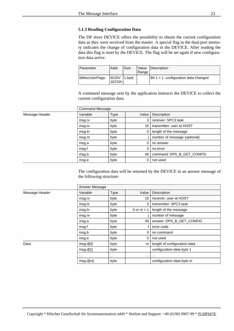
5.1.3 Reading Configuration Data
The DP slave DEVICE offers the possibility to obtain the current configurationdata as they were received from the master. A special flag in the dual-port memo-ry indicates the change of configuration data in the DEVICE. After reading thedata this flag is reset by the DEVICE. The flag will be set again if new configura-tion data arrive.
Parameter Addr. Size ValueRange
Description
bMiscUserFlags 6CDh/1ECDh
1 byte Bit 1 = 1: configuration data changed
A command message sent by the application instructs the DEVICE to collect thecurrent configuration data.
Command Message
Message Header Variable Type Value Description
msg.rx byte 3 receiver: SPC3 task
msg.tx byte 16 transmitter: user at HOST
msg.ln byte 0 length of the message
msg.nr byte j number of message (optional)
msg.a byte 0 no answer
msg.f byte 0 no error
msg.b byte 49 command: DPS_B_GET_CONFIG
msg.e byte 0 not used
The configuration data will be returned by the DEVICE in an answer message ofthe following structure:
Answer Message
Message Header Variable Type Value Description
msg.rx byte 16 receiver: user at HOST
msg.tx byte 3 transmitter: SPC3 task
msg.ln byte 0 or m + 1 length of the message
msg.nr byte j number of message
msg.a byte 49 answer: DPS_B_GET_CONFIG
msg.f byte f error code
msg.b byte 0 no command
msg.e byte 0 not used
Data msg.d[0] byte m length of configuration data
msg.d[1] byte configuration data byte 1
... ... ... ...
msg.d[m] byte configuration data byte m
The Message Interface 23
Copyright * Hilscher Gesellschaft für Systemautomation mbH * Hotline and Support: +49 (6190) 9907-99 * Pi:DPS#7E

In case of an error the variable msg.f holds an error code which indicates thereason of failure.
Error Codeat msg.f
Description
0 TASK_F_OKNo error occurred.
148 DPS_ERR_CONFIG_NOT_AVAILABLENo valid configuration data available at the moment. The DEVICE waits fornew configuration data.
152 TASK_F_MESSAGECOMMANDUnknown command at msg.b
200 TASK_F_NOT_INITIALIZEDTask not initialized
The Message Interface 24
Copyright * Hilscher Gesellschaft für Systemautomation mbH * Hotline and Support: +49 (6190) 9907-99 * Pi:DPS#7E

5.1.4 DPV1 Class 1 Alarm Request
The alarm handling mechanisms specified by PROFIBUS DPV1 are supported bythe DEVICE. In order to submit an alarm to the assigned master the HOST appli-cation should send the command message DPS_B_ACYC_C1_ALARM to theDEVICE.Each alarm must be explicitly acknowledged by the master using the AlarmAcknowlegde service. In the meantime additional alarms can be activated by theHOST application. Dependant on the current parameter data the DEVICE sup-ports up to 32 alarms beeing active in parallel. Alarms that can't be sent immedia-tely are internally queued.The DPS_B_ACYC_C1_ALARM command message has the following format:
Command Message
Message Header Variable Type Value Description
msg.rx byte 3 receiver: SPC3 task
msg.tx byte 16 transmitter: user at HOST
msg.ln byte 8 + m message length(m: number of bytes in data area)
msg.nr byte 0 ... 255 number of message
msg.a byte 0 no answer
msg.f byte 0 no error
msg.b byte 18 command: DPS_B_ACYC_C1_ALARM
msg.e byte 0 not used
Telegam Header msg.device_adr byte 0 not used
msg.data_area byte 0 not used
msg.data_adr word 0 ... 254 Slot Number
msg.data_idx byte 0 ... 31 Sequence Number
msg.data_cnt byte 0 ... 28 (m) length of user specific alarm data
msg.data_type byte 0 ... 255 Alarm Type
msg.function byte 0 ... 7 Bit 0 ... 1: Alarm SpecifierBit 2: Add Ack bit
Data msg.d[0] byte user specific data byte 1
... ... ... ...
msg.d[m-1] byte user specific data byte m
The slot number of the slot reporting the alarm should be filled into the variablemsg.data_adr. The variable msg.data_idx holds a sequence number thatis used to distinct alarms that are active at the same time. Thus the sequence num-ber must be unique to each alarm. The alarm type should be written to the varia-ble msg.data_type. The Alarm Specifier and the Add Ack bit should be spe-cified in the variable msg.function. User specific alarm data should be filledinto the data area at msg.d. The variable msg.data_idx holding the numberof user specific alarm data should be set accordingly. The DEVICE supports upto 28 bytes of user specific alarm data.For a more detailed description of all alarm parameter, please refer to the PROFI-BUS DPV1 specification.All parameter will be checked by the DEVICE. In case of an error the alarm willbe rejected and an error message will be returned to the HOST application. Elsethe alarm will be sent and the DEVICE waits for the Alarm Acknowlegde servicefrom the master. When it is received the DEVICE informs the HOST applicationof the successful alarm processing by returning an answer message.
The Message Interface 25
Copyright * Hilscher Gesellschaft für Systemautomation mbH * Hotline and Support: +49 (6190) 9907-99 * Pi:DPS#7E

The format of the answer message is the same for both error reports and successnotifications.
Answer Message
Message Header Variable Type Value Description
msg.rx byte 16 receiver: user at HOST
msg.tx byte 3 transmitter: SPC3 task
msg.ln byte 8 message length
msg.nr byte 0 ... 255 number of message
msg.a byte 18 answer: DPS_B_ACYC_C1_ALARM
msg.f byte f error code
msg.b byte 0 no command
msg.e byte 0 not used
Telegram Header msg.device_adr byte 0 not used
msg.data_area byte 0 not used
msg.data_adr word 0 ... 254 Slot Number
msg.data_idx byte 0 ... 31 Sequence Number
msg.data_cnt byte 0 not used
msg.data_type byte 0 ... 255 Alarm Type
msg.function byte 0 ... 7 Add Ack bit + Alarm Specifier
The error code at msg.f can be one of the following:
Error Codeat msg.f
Description
0 TASK_F_OKNo error
115 DPS_ERR_DIAG_TOO_LONGStatus data exceeds the length of the SPC3 diagnostic buffer
116 DPS_ERR_NO_FREE_DIAG_BUFFERNo diagnostic buffer available at the momentThis Error will be temporary.
119 DPS_ERR_ALRM_DPV1_C1_DEACTIVATEDDPV1 class 1 services are disabled
120 DPS_ERR_ALRM_OVERFLOWMaximum number of active alarms exceeded
121 DPS_ERR_ALRM_DISABLEDAlarm is disabled
123 DPS_ERR_ALRM_ILLEG_LENUser specific alarm data of illegal length
125 DPS_ERR_ALRM_ILLEG_SEQUSequence number out of range or already in use
152 TASK_F_MESSAGECOMMANDUnknown command at msg.b
165 TASK_F_DATA_CNTMismatch between length at msg.ln and length at msg.data_cnt
200 TASK_F_NOT_INITIALIZEDTask not initialized
The Message Interface 26
Copyright * Hilscher Gesellschaft für Systemautomation mbH * Hotline and Support: +49 (6190) 9907-99 * Pi:DPS#7E

5.1.5 DPV1 Class 1 Status Reports
Using the command message DPS_B_ACYC_C1_STATUS the HOST applicati-on can submit status reports to the assigned PROFIBUS-DP master.
Command Message
Message Header Variable Type Value Description
msg.rx byte 3 receiver: SPC3 task
msg.tx byte 16 transmitter: user at HOST
msg.ln byte 8+m message length(m: number of bytes in data area)
msg.nr byte j number of message (optional)
msg.a byte 0 no answer
msg.f byte 0 no error
msg.b byte 19 command: DPS_B_ACYC_C1_STATUS
msg.e byte 0 not used
Telegram Header msg.device_adr byte 0 not used
msg.data_area byte 0 not used
msg.data_adr word 0 not used
msg.data_idx byte 0 not used
msg.data_cnt byte 0 ... 32 (m) number of Status PDU bytes
msg.data_type byte 0 not used
msg.function byte 0 not used
Data msg.d[0] byte Status PDU byte 1
... ... ... ...
msg.d[m-1] byte Status PDU byte m
The status data have to be filled into the data area at msg.d in Status PDU for-mat. If more than one Status PDU has to be sent at once all Status PDUs shouldbe filled in consecutively without any gaps. The over all length of Status PDU da-ta is limited to 32 bytes.Before sending the status data the DEVICE checks the Status PDUs for its con-formity with the respective specifications. In case of violations of these specifica-tions the status message will be rejected.Please refer to the PROFIBUS DPV1 specification for a detailed description ofthe Status PDU format.After finishing conformitiy tests the DEVICE returns an answer message to theHOST application. The error code at msg.f of this answer message indicatessuccessful processing or in case of an error the failure reason.Please note that the delivery of the answer message does not imply the status datawere already fetched by the master.
The Message Interface 27
Copyright * Hilscher Gesellschaft für Systemautomation mbH * Hotline and Support: +49 (6190) 9907-99 * Pi:DPS#7E

Answer Message
Message Header Variable Type Value Description
msg.rx byte 16 receiver: user at HOST
msg.tx byte 3 transmitter: SPC3 task
msg.ln byte 8 message length
msg.nr byte j number of message
msg.a byte 19 answer: DPS_B_ACYC_C1_STATUS
msg.f byte f error code (see below)
msg.b byte 0 no command
msg.e byte 0 not used
Telegram Header msg.device_adr byte 0 not used
msg.data_area byte 0 not used
msg.data_adr word 0 not used
msg.data_idx byte 0 not used
msg.data_cnt byte 0 not used
msg.data_type byte 0 not used
msg.function byte 0 not used
The following error codes can be returned at msg.f:
Error Codeat msg.f
Description
0 TASK_F_OKNo error
115 DPS_ERR_DIAG_TOO_LONGStatus data exceeds the length of the SPC3 diagnostic buffer
116 DPS_ERR_NO_FREE_DIAG_BUFFERNo diagnostic buffer available at the momentThis Error will be temporary.
126 DPS_ERR_STAT_DPV1_DEACTIVATEDDPV1 mode currently not enabled
127 DPS_ERR_STAT_ILLEG_HEADERStatus PDU with header byte of illegal format
128 DPS_ERR_STAT_ILLEG_LENStatus PDU of illegal length or mismatch between length of Status PDUand length at msg.data_cnt
152 TASK_F_MESSAGECOMMANDUnknown command at msg.b
165 TASK_F_DATA_CNTMismatch between length at msg.ln and length at msg.data_cnt
200 TASK_F_NOT_INITIALIZEDTask not initialized
The Message Interface 28
Copyright * Hilscher Gesellschaft für Systemautomation mbH * Hotline and Support: +49 (6190) 9907-99 * Pi:DPS#7E

5.1.6 DPV1 Class 1 Read
The DP slave device supports the acyclic services Read and Write according toPROFIBUS DPV1. If a valid acyclic read indication is received one of the follo-wing command messages is sent to the user.
Command Message
Message Header Variable Type Value Description
msg.rx byte 16 receiver: user at HOST
msg.tx byte 3 transmitter: SPC3 task
msg.ln byte 8 length of the message
msg.nr byte j number of message
msg.a byte 0 no answer
msg.f byte 0 no error
msg.b byte 17 command: DPS_B_ACYC_C1_DATA
msg.e byte 0 not used
Telegram Header msg.device_adr byte 1 ... 125 bus address of originating master
msg.data_area byte 0 not used
msg.data_adr word 0 ... 254 slot number
msg.data_idx byte 0 ... 255 index
msg.data_cnt byte 0 ... 255 number of data bytes requested
msg.data_type byte 10 TASK_TDT_STRING
msg.function byte 1 TASK_TFC_READ
This command message is processed by the user application, which in turn has toprovide an answer message.
Answer Message
Message Header Variable Type Value Description
msg.rx byte 3 receiver: SPC3 task
msg.tx byte 16 transmitter: user at HOST
msg.ln byte 8 + m length of the message
msg.nr byte j number of message as specified by thebelonging command message
msg.a byte 17 answer: DPS_B_ACYC_C1_DATA
msg.f byte 0 no error
msg.b byte 0 no command
msg.e byte 0 not used
Telegram Header msg.device_adr byte 1 ... 125 bus address of originating master
msg.data_area byte 0 not used
msg.data_adr word 0 ... 254 slot number
msg.data_idx byte 0 ... 255 index
msg.data_cnt byte m number of user data bytes delivered
msg.data_type byte 10 TASK_TDT_STRING
msg.function byte 1 TASK_TFC_READ
Data msg.d[0] byte user data byte 1
... ... ... ...
msg.d[m-1] byte user data byte m
On error the application should return an error message of the following format:
The Message Interface 29
Copyright * Hilscher Gesellschaft für Systemautomation mbH * Hotline and Support: +49 (6190) 9907-99 * Pi:DPS#7E

Answer Message
Message Header Variable Type Value Description
msg.rx byte 3 receiver: SPC3 task
msg.tx byte 16 transmitter: user at HOST
msg.ln byte 10 length of the message
msg.nr byte j number of message as specified by thebelonging command message
msg.a byte 17 answer: DPS_B_ACYC_C1_DATA
msg.f byte 1 error occured
msg.b byte 0 no command
msg.e byte 0 not used
Telegram Header msg.device_adr byte 1 ... 125 bus address of originating master
msg.data_area byte 0 not used
msg.data_adr word 0 ... 254 slot number
msg.data_idx byte 0 ... 255 index
msg.data_cnt byte 2 number of error code bytes
msg.data_type byte 10 TASK_TDT_STRING
msg.function byte 1 TASK_TFC_READ
Data msg.d[0] byte error code 1 according to DPV1
msg.d[1] byte error code 2 according to DPV1
The Message Interface 30
Copyright * Hilscher Gesellschaft für Systemautomation mbH * Hotline and Support: +49 (6190) 9907-99 * Pi:DPS#7E

5.1.7 DPV1 Class 1 Write
The DP slave device supports the acyclic services Read and Write according toPROFIBUS DPV1. If a valid acyclic write indication is received one of the follo-wing command messages is sent to the user.
Command Message
Message Header Variable Type Value Description
msg.rx byte 16 receiver: user at HOST
msg.tx byte 3 transmitter: SPC3 task
msg.ln byte 8 + m length of the message
msg.nr byte j number of message
msg.a byte 0 no answer
msg.f byte 0 no error
msg.b byte 17 command: DPS_B_ACYC_C1_DATA
msg.e byte 0 not used
Telegram Header msg.device_adr byte 1 ... 125 bus address of originating master
msg.data_area byte 0 not used
msg.data_adr word 0 ... 254 slot number
msg.data_idx byte 0 ... 255 index
msg.data_cnt byte m length of user data
msg.data_type byte 10 TASK_TDT_STRING
msg.function byte 2 TASK_TFC_WRITE
Data msg.d[0] byte user data
... ... ... ...
msg.d[m-1] byte user data
This command message is processed by the user application, which in turn has toprovide an answer message. On success the application should return an answermessage as follows:
The Message Interface 31
Copyright * Hilscher Gesellschaft für Systemautomation mbH * Hotline and Support: +49 (6190) 9907-99 * Pi:DPS#7E

Answer Message
Message Header Variable Type Value Description
msg.rx byte 3 receiver: SPC3 task
msg.tx byte 16 transmitter: user at HOST
msg.ln byte 8 length of the message
msg.nr byte j number of message as specified by thebelonging command message
msg.a byte 17 answer: DPS_B_ACYC_C1_DATA
msg.f byte 0 no error
msg.b byte 0 no command
msg.e byte 0 not used
Telegram Header msg.device_adr byte 1 ... 125 bus address of originating master
msg.data_area byte 0 not used
msg.data_adr word 0 ... 254 slot number
msg.data_idx byte 0 ... 255 index
msg.data_cnt byte m length of user data
msg.data_type byte 10 TASK_TDT_STRING
msg.function byte 2 TASK_TFC_WRITE
In case of an error the returned answer should have the following structure:
Answer Message
Message Header Variable Type Value Description
msg.rx byte 3 receiver: SPC3 task
msg.tx byte 16 transmitter: user at HOST
msg.ln byte 10 length of the message
msg.nr byte j number of message as specified by thebelonging command message
msg.a byte 17 answer: DPS_B_ACYC_C1_DATA
msg.f byte 1 error occured
msg.b byte 0 no command
msg.e byte 0 not used
Telegram Header msg.device_adr byte 1 ... 125 bus address of originating master
msg.data_area byte 0 not used
msg.data_adr word 0 ... 254 slot number
msg.data_idx byte 0 ... 255 index
msg.data_cnt byte 2 number of error code bytes
msg.data_type byte 10 TASK_TDT_STRING
msg.function byte 2 TASK_TFC_WRITE
Data msg.d[0] byte error code 1 according to DPV1
msg.d[1] byte error code 2 according to DPV1
The Message Interface 32
Copyright * Hilscher Gesellschaft für Systemautomation mbH * Hotline and Support: +49 (6190) 9907-99 * Pi:DPS#7E

5.1.8 DPV1 Class 2 Init
The DPV1 class 2 capabilites of the DEVICE need to be started by sending thefollowing message before any of the DPV1 class 2 services can be used.
Command Message, MSRM2_Init.req
Message Header Variable Type Value Description
msg.rx byte 3 receiver: SPC3 task
msg.tx byte 16 transmitter: user at HOST
msg.ln byte m length of the message
msg.nr byte j number of message
msg.a byte 0 no answer
msg.f byte 0 no error
msg.b byte 44 command: DPS_B_ACYC_C2_INIT
msg.e byte 0 not used
Data msg.d[0] word Min_Send_Timeout
msg.d[2] byte Num_of_Res_SAP_List_Entries
msg.d[3] octet str Res_SAP_List
msg.d[n] byte Num_of_RM_Registry_Entries
msg.d[p] octet str RM_Registry
The time-out at Min_Send_Timeout is used during supervision of an activeDPV1 class 2 connection. It is based on units of 10 milliseconds.The Res_SAP_List variable builds up by a succession of bytes each of whichcontaining one SAP specifier. The number of bytes in this list (and thus the num-ber of SAPs) should be written to Num_of_Res_SAP_List_Entries. ValidSAPs in Res_SAP_List are the range of 0 ... 48. There must be at least oneSAP in the list. The maximum number of SAPs is limited to one by the currentfirmware. Thus the number of active class 2 connections is also limited to one ata time.In the RM_Registry each entry makes an assignment between API, SCL andmaximum PDU length (see table below). None of the Max_Len_Data_Unit va-lues must exceed the length of the allocated DPV1 class 2 PDU buffer. The varia-ble Num_of_RM_Registry_Entries holds the number of entries in theRM_Registry. The RM_Registry must contain at least one entry. The maximumnumber of entries is limited to five.
Variable Type Description
API byte application process instance
SCL byte security level
Max_Len_Data_Unit byte max. length of PDU
The DEVICE returns an answer message which informs of successful processingor failure of the request (see table below).
The Message Interface 33
Copyright * Hilscher Gesellschaft für Systemautomation mbH * Hotline and Support: +49 (6190) 9907-99 * Pi:DPS#7E

Answer Message
Message Header Variable Type Value Description
msg.rx byte 16 receiver: user at HOST
msg.tx byte 3 transmitter: SPC3 task
msg.ln byte 0 length of the message
msg.nr byte 0 ... 255 number of message as specified by thebelonging command message
msg.a byte 44 answer: DPS_B_ACYC_C2_INIT
msg.f byte f error code (see below)
msg.b byte 0 no command
msg.e byte 0 not used
In case of an error the variable msg.f holds an error code:
Error Codeat msg.f
Description
0 TASK_F_OKNo error
138 DPS_ERR_ACYC_C2_DISABLEDDPV1 class 2 services are disabled in basic configuration
139 DPS_ERR_ACYC_C2_ALREADY_ACTIVEDPV1 class 2 services are already active
141 DPS_ERR_ACYC_C2_ILLEG_RM_REGISTRYinvalid data in RM_Registry
142 DPS_ERR_ACYC_C2_ILLEG_RES_SAP_LISTinvalid SAP in Res_SAP_List
143 DPS_ERR_ACYC_C2_ILLEG_NUM_RM_REGISTRYinvalid number of entries in RM_Registry
144 DPS_ERR_ACYC_C2_ILLEG_NUM_RES_SAP_LISTinvalid number of entries in Res_SAP_List
145 DPS_ERR_ACYC_C2_ILLEG_LENmismatch between message length and length required by contained data
146 DPS_ERR_ACYC_C2_FDL_ERRORFDL error occurred
152 TASK_F_MESSAGECOMMANDUnknown command at msg.b
200 TASK_F_NOT_INITIALIZEDTask not initialized
The Message Interface 34
Copyright * Hilscher Gesellschaft für Systemautomation mbH * Hotline and Support: +49 (6190) 9907-99 * Pi:DPS#7E

5.1.9 DPV1 Class 2 Initiate
Every connection using DPV1 class 2 services must be established by the masterusing the initiate request service. If the slave DEVICE receives the respective In-itiate-REQ-PDU it notifies the user by sending the following message.
Command Message (MSAC2_Initiate.ind)
Message Header Variable Type Value Description
msg.rx byte 16 receiver: user at HOST
msg.tx byte 3 transmitter: SPC3 task
msg.ln byte m length of the message
msg.nr byte j number of message
msg.a byte 0 no answer
msg.f byte 0 no error
msg.b byte 32 command: DPS_B_ACYC_C2_INITIATE
msg.e byte 0 not used
Data msg.d[0] byte 0 ... 125 Req_Add
msg.d[1] byte 0 ... 48 Res_SAP
msg.d[2] byte Features_Supported_1
msg.d[3] byte Features_Supported_2
msg.d[4] byte Profile_Features_Supported_1
msg.d[5] byte Profile_Features_Supported_2
msg.d[6] word Profile_Ident_Number
msg.d[8] byte 0 ... 1 Add_Addr_Param.S_Type
msg.d[9] byte Add_Addr_Param.S_Len
msg.d[10] byte 0 ... 1 Add_Addr_Param.D_Type
msg.d[11] byte Add_Addr_Param.D_Len
msg.d[12] byte Add_Addr_Param.S_D_Addr[0]
... byte ...
msg.d[m-1] byte Add_Addr_Param.S_D_Addr[m-13]
The message contains all parameter data received from the Initiate-REQ-PDU.For a detailed description of all parameter, please refer to the PROFIBUS DPV1specification.
By sending the following answer message to the DEVICE the connection requestwill be accepted and thus the DPV1 class 2 connection will be established:
The Message Interface 35
Copyright * Hilscher Gesellschaft für Systemautomation mbH * Hotline and Support: +49 (6190) 9907-99 * Pi:DPS#7E

Answer Message, MSAC2_Initiate.res (+)
Message Header Variable Type Value Description
msg.rx byte 3 receiver: SPC3 task
msg.tx byte 16 transmitter: user at HOST
msg.ln byte m length of the message
msg.nr byte j number of message as specified by thebelonging command message
msg.a byte 32 answer: DPS_B_ACYC_C2_INITIATE
msg.f byte 0 no error
msg.b byte 0 no command
msg.e byte 0 not used
Data msg.d[0] byte 0 ... 48 Res_SAP
msg.d[1] byte Features_Supported_1
msg.d[2] byte Features_Supported_2
msg.d[3] byte Profile_Features_Supported_1
msg.d[4] byte Profile_Features_Supported_2
msg.d[5] word Profile_Ident_Number
msg.d[7] byte 0 ... 1 Add_Addr_Param.S_Type
msg.d[8] byte Add_Addr_Param.S_Len
msg.d[9] byte 0 ... 1 Add_Addr_Param.D_Type
msg.d[10] byte Add_Addr_Param.D_Len
msg.d[11] byte Add_Addr_Param.S_D_Addr[0]
... byte ...
msg.d[m-1] byte Add_Addr_Param.S_D_Addr[m-13]
If the application detects an error during processing of the initiate message itshould return a negative response message according to the following table:
Answer Message: MSAC2_Initiate.res (-)
Message Header Variable Type Value Description
msg.rx byte 3 receiver: SPC3 task
msg.tx byte 16 transmitter: user at HOST
msg.ln byte 3 length of the message
msg.nr byte j number of message as specified by thebelonging command message
msg.a byte 32 answer: DPS_B_ACYC_C2_INITIATE
msg.f byte 1 error occured
msg.b byte 0 no command
msg.e byte 0 not used
Data msg.d[0] byte 0 ... 48 Res_SAP
msg.d[1] byte Error_Code_1
msg.d[2] byte Error_Code_2
Please refer to the PROFIBUS DPV1 specification for a detailed explanation ofthe error codes available for Error_Code_1 and Error_Code_2.
The Message Interface 36
Copyright * Hilscher Gesellschaft für Systemautomation mbH * Hotline and Support: +49 (6190) 9907-99 * Pi:DPS#7E

5.1.10 DPV1 Class 2 Read
Once a connection is established the master can request data from the slave DE-VICE using the DPV1 class 2 read service.
Command Message, MSAC2_Read.ind
Message Header Variable Type Value Description
msg.rx byte 16 receiver: user at HOST
msg.tx byte 3 transmitter: SPC3 task
msg.ln byte 8 length of the message
msg.nr byte j number of message
msg.a byte 0 no answer
msg.f byte 0 no error
msg.b byte 33 command: DPS_B_ACYC_C2_DATA
msg.e byte 0 not used
Telegram Header msg.device_adr byte 1 ... 125 Req_Add
msg.data_area byte 0 ... 48 Res_SAP
msg.data_adr word 0 ... 254 Slot_Number
msg.data_idx byte 0 ... 255 Index
msg.data_cnt byte 0 ... 255 Length
msg.data_type byte 10 TASK_TDT_STRING
msg.function byte 1 TASK_TFC_READ
The data area to be read from is addressed by the variables Slot_Number andIndex. The variable Length holds the number of bytes to be read.
The user application returns the actual number of bytes read from the specifiedslot number and index and the data itself in the following message:
The Message Interface 37
Copyright * Hilscher Gesellschaft für Systemautomation mbH * Hotline and Support: +49 (6190) 9907-99 * Pi:DPS#7E

Answer Message, MSAC2_Read.res (+)
Message Header Variable Type Value Description
msg.rx byte 3 receiver: SPC3 task
msg.tx byte 16 transmitter: user at HOST
msg.ln byte 8 + m length of the message
msg.nr byte j number of message as specified by thebelonging command message
msg.a byte 33 answer: DPS_B_ACYC_C2_DATA
msg.f byte 0 no error
msg.b byte 0 no command
msg.e byte 0 not used
Telegram Header msg.device_adr byte not used
msg.data_area byte 0 ... 48 Res_SAP
msg.data_adr word 0 ... 254 Slot_Number
msg.data_idx byte 0 ... 255 Index
msg.data_cnt byte m Length (user data bytes delivered)
msg.data_type byte 10 TASK_TDT_STRING
msg.function byte 1 TASK_TFC_READ
Data msg.d[0] byte user data byte 1
... ... ... ...
msg.d[m-1] byte user data byte m
If the read operation cannot be processed the application should return a negativeresponse message according to the table below.
Answer Message, MSAC2_Read.res (-)
Message Header Variable Type Value Description
msg.rx byte 3 receiver: SPC3 task
msg.tx byte 16 transmitter: user at HOST
msg.ln byte 10 length of the message
msg.nr byte j number of message as specified by thebelonging command message
msg.a byte 33 answer: DPS_B_ACYC_C2_DATA
msg.f byte 1 error occured
msg.b byte 0 no command
msg.e byte 0 not used
Telegram Header msg.device_adr byte not used
msg.data_area byte 0 ... 48 Res_SAP
msg.data_adr word 0 ... 254 Slot_Number
msg.data_idx byte 0 ... 255 Index
msg.data_cnt byte 2 number of error bytes
msg.data_type byte 10 TASK_TDT_STRING
msg.function byte 1 TASK_TFC_READ
Data msg.d[0] byte Error_Code_1
msg.d[1] byte Error_Code_2
The Message Interface 38
Copyright * Hilscher Gesellschaft für Systemautomation mbH * Hotline and Support: +49 (6190) 9907-99 * Pi:DPS#7E

5.1.11 DPV1 Class 2 Write
Using the using the DPV1 class 2 write service the master can transfer data to theslave. If an Write-REQ-PDU is received by the slave DEVICE the following mes-sage is sent to the user application.
Command Message, MSAC2_Write.ind
Message Header Variable Type Value Description
msg.rx byte 16 receiver: user at HOST
msg.tx byte 3 transmitter: SPC3 task
msg.ln byte m + 8 length of the message
msg.nr byte j number of message
msg.a byte 0 no answer
msg.f byte 0 no error
msg.b byte 33 command: DPS_B_ACYC_C2_DATA
msg.e byte 0 not used
Telegram Header msg.device_adr byte 1 ... 125 Req_Add
msg.data_area byte 0 ... 48 Res_SAP
msg.data_adr word 0 ... 254 Slot_Number
msg.data_idx byte 0 ... 255 Index
msg.data_cnt byte m Length
msg.data_type byte 10 TASK_TDT_STRING
msg.function byte 2 TASK_TFC_WRITE
Data msg.d[0] byte user data byte 1
... ... ... ...
msg.d[m-1] byte user data byte m
The data at msg.d[0] ... msg.d[m-1] should be copied to the data area ad-dressed by Slot_Number and Index. The value at Length specifies thenumber of bytes to be written.
The Message Interface 39
Copyright * Hilscher Gesellschaft für Systemautomation mbH * Hotline and Support: +49 (6190) 9907-99 * Pi:DPS#7E

On success the the user application returns the actual number of bytes written inthe following message:
Answer Message, MSAC2_Write.res (+)
Message Header Variable Type Value Description
msg.rx byte 3 receiver: SPC3 task
msg.tx byte 16 transmitter: user at HOST
msg.ln byte 8 length of the message
msg.nr byte j number of message as specified by thebelonging command message
msg.a byte 33 answer: DPS_B_ACYC_C2_DATA
msg.f byte 0 no error
msg.b byte 0 no command
msg.e byte 0 not used
Telegram Header msg.device_adr byte not used
msg.data_area byte 0 ... 48 Res_SAP
msg.data_adr word 0 ... 254 Slot_Number
msg.data_idx byte 0 ... 255 Index
msg.data_cnt byte m Length (user data bytes written)
msg.data_type byte 10 TASK_TDT_STRING
msg.function byte 2 TASK_TFC_WRITE
If the write operation cannot be processed the application should return a negati-ve response message according to the table below.
Answer Message, MSAC2_Write.res (-)
Message Header Variable Type Value Description
msg.rx byte 3 receiver: SPC3 task
msg.tx byte 16 transmitter: user at HOST
msg.ln byte 10 length of the message
msg.nr byte j number of message as specified by thebelonging command message
msg.a byte 33 answer: DPS_B_ACYC_C2_DATA
msg.f byte 1 error occured
msg.b byte 0 no command
msg.e byte 0 not used
Telegram Header msg.device_adr byte not used
msg.data_area byte 0 ... 48 Res_SAP
msg.data_adr word 0 ... 254 Slot_Number
msg.data_idx byte 0 ... 255 Index
msg.data_cnt byte 2 number of error bytes
msg.data_type byte 10 TASK_TDT_STRING
msg.function byte 2 TASK_TFC_WRITE
Data msg.d[0] byte Error_Code_1
msg.d[1] byte Error_Code_2
The Message Interface 40
Copyright * Hilscher Gesellschaft für Systemautomation mbH * Hotline and Support: +49 (6190) 9907-99 * Pi:DPS#7E

5.1.12 DPV1 Class 2 Data Transport
Using the using the DPV1 class 2 data transport service the master can transferdata to the slave and request data from the slave within one single service. If anDataTransport-REQ-PDU is received by the DEVICE the following message issent to the user application.
Command Message, MSAC2_Data_Transport.ind
Message Header Variable Type Value Description
msg.rx byte 16 receiver: user at HOST
msg.tx byte 3 transmitter: SPC3 task
msg.ln byte m + 8 length of the message
msg.nr byte j number of message
msg.a byte 0 no answer
msg.f byte 0 no error
msg.b byte 33 command: DPS_B_ACYC_C2_DATA
msg.e byte 0 not used
Telegram Header msg.device_adr byte 1 ... 125 Req_Add
msg.data_area byte 0 ... 48 Res_SAP
msg.data_adr word 0 ... 254 Slot_Number
msg.data_idx byte 0 ... 255 Index
msg.data_cnt byte m Length
msg.data_type byte 10 TASK_TDT_STRING
msg.function byte 3 TASK_TFC_DATA_TRANSPORT
Data msg.d[0] byte user data byte 1
... ... ... ...
msg.d[m-1] byte user data byte m
The data at msg.d[0] ... msg.d[m-1] should be copied to the data area ad-dressed by Slot_Number and Index. The variable Length specifies thenumber of bytes to be written.
The user application returns a number of bytes read from the specified slot num-ber and index and the data itself in the following answer message:
The Message Interface 41
Copyright * Hilscher Gesellschaft für Systemautomation mbH * Hotline and Support: +49 (6190) 9907-99 * Pi:DPS#7E

Answer Message, MSAC2_Data_Transport.res (+)
Message Header Variable Type Value Description
msg.rx byte 3 receiver: SPC3 task
msg.tx byte 16 transmitter: user at HOST
msg.ln byte 8 + m length of the message
msg.nr byte j number of message as specified by thebelonging command message
msg.a byte 33 answer: DPS_B_ACYC_C2_DATA
msg.f byte 0 no error
msg.b byte 0 no command
msg.e byte 0 not used
Telegram Header msg.device_adr byte not used
msg.data_area byte 0 ... 48 Res_SAP
msg.data_adr word 0 ... 254 Slot_Number
msg.data_idx byte 0 ... 255 Index
msg.data_cnt byte m Length (user data bytes delivered)
msg.data_type byte 10 TASK_TDT_STRING
msg.function byte 3 TASK_TFC_DATA_TRANSPORT
Data msg.d[0] byte user data byte 1
... ... ... ...
msg.d[m-1] byte user data byte m
If the data transport operation cannot be processed the application should return anegative response message according to the table below.
Answer Message, MSAC2_Data_Transport.res (-)
Message Header Variable Type Value Description
msg.rx byte 3 receiver: SPC3 task
msg.tx byte 16 transmitter: user at HOST
msg.ln byte 10 length of the message
msg.nr byte j number of message as specified by thebelonging command message
msg.a byte 33 answer: DPS_B_ACYC_C2_DATA
msg.f byte 1 error occured
msg.b byte 0 no command
msg.e byte 0 not used
Telegram Header msg.device_adr byte not used
msg.data_area byte 0 ... 48 Res_SAP
msg.data_adr word 0 ... 254 Slot_Number
msg.data_idx byte 0 ... 255 Index
msg.data_cnt byte 2 number of error bytes
msg.data_type byte 10 TASK_TDT_STRING
msg.function byte 3 TASK_TFC_DATA_TRANSPORT
Data msg.d[0] byte Error_Code_1
msg.d[1] byte Error_Code_2
The Message Interface 42
Copyright * Hilscher Gesellschaft für Systemautomation mbH * Hotline and Support: +49 (6190) 9907-99 * Pi:DPS#7E

5.1.13 DPV1 Class 2 Abort
A DPV1 class 2 connection can be aborted by the user application at any time bysending a DPS_B_ACYC_C2_ABORT command to the DEVICE.
Command Message, MSAC2_Abort.req
Message Header Variable Type Value Description
msg.rx byte 3 receiver: SPC3 task
msg.tx byte 16 transmitter: user at HOST
msg.ln byte 3 length of the message
msg.nr byte j number of message
msg.a byte 0 no answer
msg.f byte 0 no error
msg.b byte 47 command: DPS_B_ACYC_C2_ABORT
msg.e byte 0 not used
Data msg.d[0] byte 0 ... 48 Res_SAP
msg.d[1] byte 0 ... 255 Subnet
msg.d[2] byte 0 ... 16 Reason_Code (see below)
The Res_SAP variable identifies the connection to be aborted. Using the varia-ble Subnet the user can give some more information about the location of theerror source which caused the abort request. The variable Reason_Code indica-tes the reason for the abort request.Please refer to the PROFIBUS DPV1 specification for valid subnet and reasoncodes.
The DEVICE returns an answer message which indicates successful processingor failure of the abort request.
Answer Message
Message Header Variable Type Value Description
msg.rx byte 16 receiver: user at HOST
msg.tx byte 3 transmitter: SPC3 task
msg.ln byte 0 length of the message
msg.nr byte 0 ... 255 number of message as specified by thebelonging command message
msg.a byte 47 answer: DPS_B_ACYC_C2_ABORT
msg.f byte f error code (see below)
msg.b byte 0 no command
msg.e byte 0 not used
The error code at msg.f is one of the following:
The Message Interface 43
Copyright * Hilscher Gesellschaft für Systemautomation mbH * Hotline and Support: +49 (6190) 9907-99 * Pi:DPS#7E

Error Codeat msg.f
Description
0 TASK_F_OKNo error
140 DPS_ERR_ACYC_C2_DEACTIVATEDDPV1 class 2 services are currently not activated
145 DPS_ERR_ACYC_C2_ILLEG_LENIllegal message length
147 DPS_ERR_ACYC_C2_ILLEG_SAPSAP is unknwon or SAP has currently no connection established
152 TASK_F_MESSAGECOMMANDUnknown command at msg.b
200 TASK_F_NOT_INITIALIZEDTask not initialized
The Message Interface 44
Copyright * Hilscher Gesellschaft für Systemautomation mbH * Hotline and Support: +49 (6190) 9907-99 * Pi:DPS#7E

5.1.14 DPV1 Class 2 Aborted
The DEVICE sends an DPS_B_ACYC_C2_ABORT indication to the user appli-cation if an established DPV1 class 2 connection was aborted by an explicit abortcommand from the master, an internal error condition or a time-out.
Command Message, MSAC2_Abort.ind
Message Header Variable Type Value Description
msg.rx byte 16 receiver: user at HOST
msg.tx byte 3 transmitter: SPC3 task
msg.ln byte 3 length of the message
msg.nr byte 0 ... 255 number of message
msg.a byte 0 no answer
msg.f byte 0 no error
msg.b byte 47 command: DPS_B_ACYC_C2_ABORT
msg.e byte 0 not used
Data msg.d[0] byte 0 ... 48 Res_SAP
msg.d[1] byte 0 ... 255 Locally_Generated
msg.d[2] byte 0 ... 255 Subnet
msg.d[3] byte 0 ... 31 Reason_Code
5.1.15 DPV1 Class 2 Fault
In case of a severe error all established DPV1 class 2 connections will be abortedand processing of DPV1 class 2 requests will be stopped. ADPS_B_ACYC_C2_FAULT message will be sent to the user application. To re-enable DPV1 class 2 processing a new DPS_B_ACYC_C2_INIT command needsto be issued to the DEVICE.
Command Message, MSAC2_Fault.ind
Message Header Variable Type Value Description
msg.rx byte 16 receiver: user at HOST
msg.tx byte 3 transmitter: SPC3 task
msg.ln byte 0 length of the message
msg.nr byte 0 ... 255 number of message
msg.a byte 0 no answer
msg.f byte 0 no error
msg.b byte 45 command: DPS_B_ACYC_C2_FAULT
msg.e byte 0 not used
The Message Interface 45
Copyright * Hilscher Gesellschaft für Systemautomation mbH * Hotline and Support: +49 (6190) 9907-99 * Pi:DPS#7E